u blox Malmo 071902 Bluetooth IO Module User Manual
u-blox Malmo AB Bluetooth IO Module Users Manual
Users Manual

Utfärdare / Issued by Datum / Date Beteckning / Ref. Sida / Page
Andreas Hörjel, Mats Andersson 2005-06-08 cBProject-0403-01 (23) 1 (61)
Ärende / Subjekt Godkänd av / Approved by
BT IO Functional Descri
p
tion
Template update: 00-12-01
BT IO
Functional Description
BT IO

Utfärdare / Issued by Datum / Date Beteckning / Ref. Sida / Page
Andreas Hörjel, Mats Andersson 2005-06-08 cBProject-0403-01 (23) 2 (61)
Ärende / Subjekt Godkänd av / Approved by
BT IO Functional Descri
p
tion
Template update: 00-12-01
Table of content
BT IO Functional Description..................................................................................................... 1
BT IO ....................................................................................................................................................... 1
1 Scope....................................................................................................................................... 3
1.1 Identification................................................................................................................................ 3
1.2 System Overview ......................................................................................................................... 3
1.3 Document Overview .................................................................................................................... 4
2 References.............................................................................................................................. 5
3 Revision History.................................................................................................................... 6
4 BT IO...................................................................................................................................... 8
4.1 Overview...................................................................................................................................... 8
4.2 Hardware (Basic 2) .................................................................................................................... 10
4.3 Bus Unit (Basic 2)...................................................................................................................... 16
4.4 IO Unit (Basic 2)........................................................................................................................ 17
4.5 Common Bus and IO Unit functionality (Basic 2)..................................................................... 22
4.6 I2C Memory Plug (Basic 2) .......................................................................................................24
4.7 IO Unit Configuration................................................................................................................ 25
4.8 Bus Unit Configuration (Basic 1) .............................................................................................. 26
4.9 Configuration Management (Basic 2)........................................................................................ 26
4.10 Additional PSKeys..................................................................................................................... 27
4.11 Diagnostics and Management Protocol (Step 2)(Diagnostics)................................................. 27
4.12 Data Communication between the host and the Bus unit (Basic 2)........................................... 45
4.13 Data flow between the Bus Unit host and the BT Host CPU .................................................... 49
4.14 Connection Establishment (Basic 2).......................................................................................... 51
4.15 Security (Basic 2)....................................................................................................................... 54
4.16 Fail-safe mode (Basic 2) ............................................................................................................ 54
4.17 “Polling” scheme and latency....................................................................................................56
4.18 Point-to-point scenario and latency............................................................................................ 56
4.19 Multi-point scenario and latency ............................................................................................... 57
4.20 Range (Basic 2).......................................................................................................................... 57
4.21 Power consumption (Basic 2).................................................................................................... 57
5 Qualification and Test (Basic 2)......................................................................................... 59
6 Regulatory Information...................................................................................................... 60
6.1 FCC Compliance........................................................................................................................ 60
6.2 IC Compliance ........................................................................................................................... 61
6.3 Safety ......................................................................................................................................... 61
6.4 Label and manual requirements for the End Product................................................................. 61

Utfärdare / Issued by Datum / Date Beteckning / Ref. Sida / Page
Andreas Hörjel, Mats Andersson 2005-06-08 cBProject-0403-01 (23) 3 (61)
Ärende / Subjekt Godkänd av / Approved by
BT IO Functional Descri
p
tion
Template update: 00-12-01
1 Scope
1.1 Identification
This document is the functional description for the Bluetooth IO product, referenced as document
cBProject-0430-01.
The product is identified as cB-0719-02.
1.2 System Overview
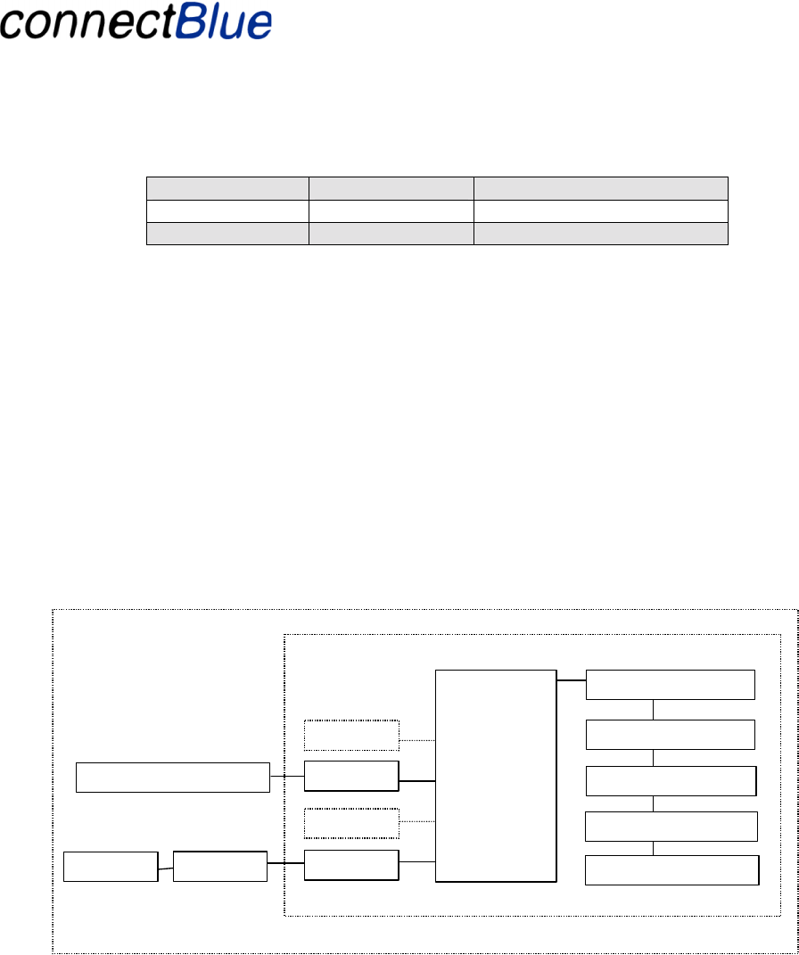
The BT IO connects an IO using the wireless Bluetooth technology to a field bus. The field bus
connection makes it possible for superior systems, i.e. a PLC, to communicate with the IO.
The BT IO product defines two roles in the system, the Bus Unit and the IO Unit:
• Scenario 1. The Bus Unit, which connects the wireless BT IO to the field bus and further on
to the information acquiring system (PLC).
• Scenario 2. The IO Unit, which actuates the outputs and reads the inputs. Two IO units may
also be used to form an IO-to-IO mirroring application, later called the Gateway option.
Bus Unit
IO Unit
PLC
Scenario 1
IO Unit
IO Unit
BT IO
Scenario 2
BT IO
Figure 1 - Displays the system overview for the BT IO and its user scenarios

Utfärdare / Issued by Datum / Date Beteckning / Ref. Sida / Page
Andreas Hörjel, Mats Andersson 2005-06-08 cBProject-0403-01 (23) 4 (61)
Ärende / Subjekt Godkänd av / Approved by
BT IO Functional Descri
p
tion
Template update: 00-12-01
The system shall be easy to use and deploy and use standard protocols for increased interoperability
and freedom of choice.
1.3 Document Overview
The document is divided into several parts. The first part discusses the functionality of the BT IO
along with its hardware design. Part two addresses the functionality of system.
The intention is to divide the development project into several steps. What is included within in the
different steps are marked with the following (within parentheses):
(1) Basic 1. Basic 1 indicates a basic SW functionality that may enhance the currently available
prototype and may execute in the current prototype HW. This includes a limited simple multi-
point support.
(2) Basic 2. Basic functionality including a new HW. This has limited latency requirements and
no diagnostics functionality.
(3) Step 2. A second step with the goal to reach full functionality with advanced latency support,
multi-point support and full diagnostics interface.
(4) Robot. Enhancement needed for the robot tool application only.
(5) Gateway. Optional functionality where to units can be connected mirroring the digital and
analog IO over the Bluetooth link. Will only exist in a point-to-point version. This option
requires Basic 1 and Basic 2.
(6) Diagnostics. A subset of the Step 2 functionality with support for diagnostics messages.
(7) I2C Management. Added functionality to support I2C management over the
diagnostics/management interface.
Note! The current version of the documents focuses on the first steps of the project (Basic 1, Basic 2,
Gateway, Diagnostics and I2C Management). For certain parts of the document there is descriptions
for future parts as well but these parts shall not by now be considered as complete.

Utfärdare / Issued by Datum / Date Beteckning / Ref. Sida / Page
Andreas Hörjel, Mats Andersson 2005-06-08 cBProject-0403-01 (23) 5 (61)
Ärende / Subjekt Godkänd av / Approved by
BT IO Functional Descri
p
tion
Template update: 00-12-01
2 References
Reference Description
1 Bluetooth HID Profile, Revision 1.0
2 Bluetooth Core Specification, Revision 1.2
3 RSSI, Link Quality and Out-of-Range Indication, Application Note, July 2002
4 RAD-ISM-2400-ANT-PAN-8-0; antenna datasheet
5 RAD-ISM-2400-ANT-OMNI-2-1; antenna datasheet
6 RAD-ISM-2400-ANT-OMNI-9-0; antenna datasheet
7 WCR2400SMA, antenna datasheet
8 pstn-2400s-_500-308, antenna datasheet

Utfärdare / Issued by Datum / Date Beteckning / Ref. Sida / Page
Andreas Hörjel, Mats Andersson 2005-06-08 cBProject-0403-01 (23) 6 (61)
Ärende / Subjekt Godkänd av / Approved by
BT IO Functional Descri
p
tion
Template update: 00-12-01
3 Revision History
Versio
n Responsible Description
1 Andreas Hörjel Initial version
2 Mats Andersson Modified after internal connectBlue revision
3 Mats Andersson Modified after meeting in Malmö 7th April 2004
4 Mats Andersson Added basic support for a multi-point use case not optimised
for latency. Marked with italic.
5 Mats Andersson Divided into steps. Functions (chapters) marked with the
following:
(1) Basic 1 = Support for the basic multipoint with low
latency requirements. Executes on prototype HW.
(2) Basic 2 = Full product with basic requirements and
new HW.
(3) Step 2 = Added full functionality.
(4) Robot = Robot tool specific.
6 Mats Andersson Updated + more detailed spec. of the diagnostics support.
Mounting alternatives for short-range and long-range
removed. All modules are long-range.
7 Andreas
Hörjel/Mats
Andersson
Updated + shift register data packet UART<->UART
configuration and Channel id handshake.
8 Andreas
Hörjel/Mats
Andersson
First Update after project meeting 04.09.17. Remaining
question is indicated by a bold, italic and red text comment.
Added the Gateway option.
9 Mats Andersson Update after review by Phoenix Contact.
Revision of PIO usage. Use IO to indicate link quality and
failsafe mode.
Added support for a B-to-B connector.
Revised messaging interface.
10 Mats Andersson Added support for auto-pairing.
Corrected errors in PIO pinning.
No HW outline and changed pinning order.
11 Mats Andersson Added support for diagnostics messages based on the list
from Mr Fuhs.
12 Mats Andersson Added support for I2C management over the UART
interface.
13 Mats Andersson Analog IO Voltage is 0 – 2.5 V not 0 – 1.8 V

Utfärdare / Issued by Datum / Date Beteckning / Ref. Sida / Page
Andreas Hörjel, Mats Andersson 2005-06-08 cBProject-0403-01 (23) 7 (61)
Ärende / Subjekt Godkänd av / Approved by
BT IO Functional Descri
p
tion
Template update: 00-12-01
BER as a PWM output
Added PSKEYS for the analog calibration feature.
Added PSKEY for limiting of the output power to support
hi-gain antennas.
Added PSKEY for changing the Bluetooth Name
Added type approved antennas.
14 Mats Andersson Added support for connectBlue antennas
More details about output power limitation.
Added Regulatory Information chapter.
Link quality indicator updates every 5 second
Updated introduction.
Block diagram added.
Digital filterering.
15 Mats Andersson Modified FCC Statement
16 Mats Andersson Added STX in message structure for the data and
diagnostics messages.
17 Mats Andersson Modified power table settings.
18 Mats Andersson Added an example of how to use max output power setting.
19 Mats Andersson Additional items in the Regulatory chapter for IC
compliance and safety.
20 Mats Andersson Adding label and end user manual information and
requirements.
21 Mats Andersson Added a table showing the appropriate power settings to
reach a maximum of 100 mW.
Added new label positions.
22 Mats Andersson Updated power table starting at 16dBm and 4 dBm steps.
New levels for the link quality indicator.
Byte order modified for the UART data message.
23 Mats Andersson Synchronous UART protocol.
Modified Regulatory chapter.
Modified product name.

Utfärdare / Issued by Datum / Date Beteckning / Ref. Sida / Page
Andreas Hörjel, Mats Andersson 2005-06-08 cBProject-0403-01 (23) 8 (61)
Ärende / Subjekt Godkänd av / Approved by
BT IO Functional Descri
p
tion
Template update: 00-12-01
4 BT IO
4.1 Overview
The BT unit is a Bluetooth unit that is designed for sending of IO data and diagnostics information.
The unit is designed with:
1. Both external and optionally an internal antenna.
2. Long-range (100 mW) radio.
3. UART, PIO, AIO, Power and I2C interface easily accessible from two different connector
alternatives.
The unit is mounted on a motherboard using solder pads on the edges of the unit or from a one-piece
part board-to-board connector. This makes the module easy to design in on the motherboard.
Utfärdare / Issued by Datum / Date Beteckning / Ref. Sida / Page
Andreas Hörjel, Mats Andersson 2005-06-08 cBProject-0403-01 (23) 9 (61)
Ärende / Subjekt Godkänd av / Approved by
BT IO Functional Descri
p
tion
Template update: 00-12-01
0402
0402
G1
F1
E1
BAR63
0402
0402
0402
0402
0402
0402
0402
0402
0402
0402
0402
0402
0402
0402
0402
0402
0402
0402
0402
0402
0402
0402
0402
0402
0402
0402
04020402
0402
0402
0402
0402
0402
0603
0402
0603
0402
0402
0402
0402
0402
0402
0402
0402
0402
0402
0402
0402
0402
0402
04020402
0402
0402
0402
0402
0402
04020402
04020402
0402040204020402
0402
04020402
0402
0402
0402
0402
0402
0402
0402
0402
0402
BAR63
0603
0603
0603
0603
0402
0402
0402
0402
0402
0402
0402
0402
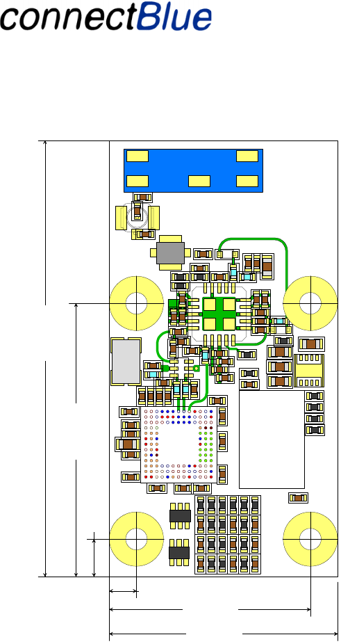
570mil transmissionline on L-2
0402
2.50 mm
18.50 mm
3.43 mm25.05 mm
40.00 mm
21.00 mm
Figure 2 - Displays an overview of the BT unit
The hardware for the BT IO units is based on the CSR (Cambridge Silicon Radio) BC03 MultiMedia
module (BC03-MM) and equipped with an external Power Amplifier (PA) for the output and a Low
Noise Amplifier (LNA) for the input.
Utfärdare / Issued by Datum / Date Beteckning / Ref. Sida / Page
Andreas Hörjel, Mats Andersson 2005-06-08 cBProject-0403-01 (23) 10 (61)
Ärende / Subjekt Godkänd av / Approved by
BT IO Functional Descri
p
tion
Template update: 00-12-01
4.2 Hardware (Basic 2)
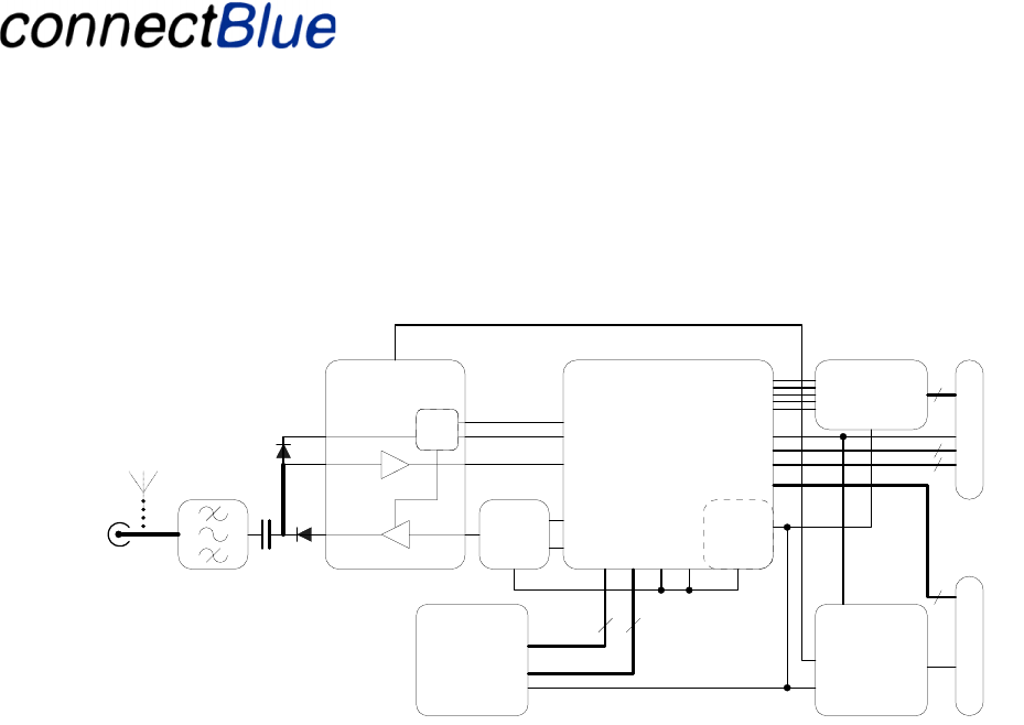
4.2.1 Block Diagram
ADR[0..18]
Power
supply
CSR BC352239A
Radio & Baseband
Bluetooth IC
FLASH 8Mbit
DATA[0..15]
+3V
+3V-PA Vin
Power supply
+1V8
Vin
(2.2V - 4.2V)
ATMEL T7024
PA/LNA
TX-
BALUN
16
13
TX/RX-switch
TX-B
TX-A
RF-in
PIO-1
PIO-0
TX/RX
control
Analog
-I/O
Digital-I/O
UART
SPI
RESET-n
Analog
Interface
4
4
4
External
Antenna connector
J1
Optional
Internal Antenna
J2
J3
Module Interface
19
Figure 3 - HW Block Diagram
Utfärdare / Issued by Datum / Date Beteckning / Ref. Sida / Page
Andreas Hörjel, Mats Andersson 2005-06-08 cBProject-0403-01 (23) 11 (61)
Ärende / Subjekt Godkänd av / Approved by
BT IO Functional Descri
p
tion
Template update: 00-12-01
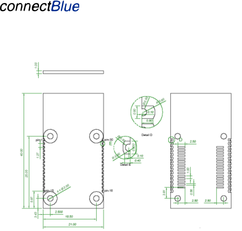
4.2.2 Basic Layout and Mechanical Design
Figure 4 – PCB Outline
4.2.3 Electrical Interfaces
The BT unit exposes six interfaces that are used for communication e.g. for diagnostics, configuration
and data communication purposes + an interface for an external antenna.
The standard antenna configuration is an UFL connector for an external antenna. The PCB is
prepared for use with an internal antenna. .
Utfärdare / Issued by Datum / Date Beteckning / Ref. Sida / Page
Andreas Hörjel, Mats Andersson 2005-06-08 cBProject-0403-01 (23) 12 (61)
Ärende / Subjekt Godkänd av / Approved by
BT IO Functional Descri
p
tion
Template update: 00-12-01
I2C
UART
PIO
AIO
BC03
Module
BT unit
PA
LNA
Antenna connectors
Power
SPI
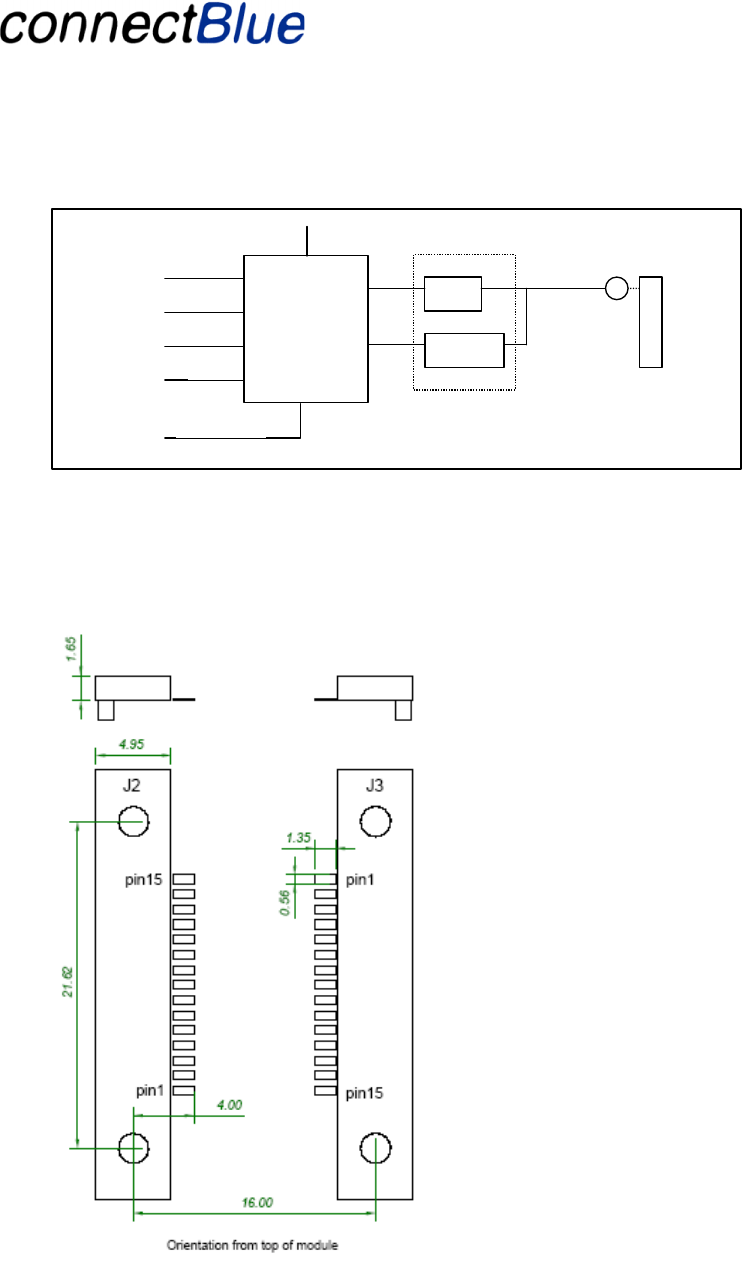
Figure 5 - Displays the all-possible interfaces of the BT unit.
The connection are available as soldering pads (see Figure 4) or at pads to be used by a Samtec board-
to-board connector with the Samtec part number SEI-115-02-GF-S-M-TR. See Figure 6 for the pin
numbering of the connector on the motherboard.
Figure 6 - Pinning of the Samtec connector on the motherboard

Utfärdare / Issued by Datum / Date Beteckning / Ref. Sida / Page
Andreas Hörjel, Mats Andersson 2005-06-08 cBProject-0403-01 (23) 13 (61)
Ärende / Subjekt Godkänd av / Approved by
BT IO Functional Descri
p
tion
Template update: 00-12-01
4.2.3.1 General Purpose I/O
All General Purpose IO are logic level 0V – 3.3V.
Maximum load on all GPIO are 4mA.
Module
Pin nr. Connector
Terminal Pin Name Type Description
28 J3-pin-3 DigIO-0 GPIO
Connected to PIO-2, bi-directional programmable pull-up/down
27 J3-pin-4 DigIO-1 GPIO Connected to PIO-3, bi-directional programmable pull-up/down
26 J3-pin-5 DigIO-2 GPIO
Connected to PIO-4, bi-directional programmable pull-up/down
25 J3-pin-6 DigIO-3 GPIO Connected to PIO-5, bi-directional programmable pull-up/down
24 J3-pin-7 DigIO-4 GPIO
Connected to PIO-6, I2C_SCL
23 J3-pin-8 DigIO-5 GPIO Connected to PIO-7, I2C_SDA
22 J3-pin-9 DigIO-6 GPIO
Connected to PIO-8, I2C_WP-n
21 J3-pin-10 DigIO-7 GPIO Connected to PIO-9, bi-directional programmable pull-up/down
20 J3-pin-11 DigIO-8 GPIO
Connected to PIO-10, bi-directional programmable pull-up/down
19 J3-pin-12 DigIO-9 GPIO Connected to PIO-11, bi-directional programmable pull-up/down
18 J3-pin-13 AuxIO-0 AuxIO
Connected to AuxIO-0, 8-bit analog IO
17 J3-pin-14 AuxIO-1 AuxIO Connected to AuxIO-1, selectable analog/digital-IO
16 J3-pin-15 AuxIO-2 AuxIO
Connected to AuxIO-3, selectable analog/digital-IO
General Purpose IO Use (used later in the document)
Active High (3.3 V)
Not Active Low (0.0 V)
4.2.3.2 Analog-I/O
The analog input and outputs signal level is between 0 – 2.5V.
Use VSS-AIO as GND reference and return path.
Module
Pin nr. Connector
Terminal Pin Name Type Description
11 J2-pin-5
AnaOUT-2 Output Connected to Audio-out-right
12 J2-pin-4 AnaOUT-1 Output Connected to Audio-out-left
13 J2-pin-3
VSSAIO Power
GND pin dedicated to Analog-IO
14 J2-pin-2 AnaIN-2 Input Connected to Audio-in-right
15 J2-pin-1
AnaIN-1 Input
Connected to Audio-in-left
4.2.3.3 Logic level SPI-communication
Module
Pin nr. Connector
Terminal Pin Name Type Description Level
6 J2-pin-10
SPI-MOSI Input SPI data input 0V/3V
7 J2-pin-9 SPI-Clk Input SPI clock input 0V/3V
8 J2-pin-8
SPI-CSB Input
SPI Chip select, active low 0V/3V
9 J2-pin-7 SPI-MISO Output SPI Data output 0V/3V

Utfärdare / Issued by Datum / Date Beteckning / Ref. Sida / Page
Andreas Hörjel, Mats Andersson 2005-06-08 cBProject-0403-01 (23) 14 (61)
Ärende / Subjekt Godkänd av / Approved by
BT IO Functional Descri
p
tion
Template update: 00-12-01
10 J2-pin-6
Reset-n Input
Module reset active low 0V/3V
Used for debugging, programming and reprogramming of the unit. It is highly recommended to have
this connector accessible on the IO motherboard.
4.2.3.4 Logic level UART-communication
Module
Pin nr. Connector
Terminal Pin Name Type Description Level
2 J2-pin-14
Rx Input
Receive data 0V/3V
3 J2-pin-13 RTS Output Request to Send 0V/3V
4 J2-pin-12
Tx Output
Transmit data 0V/3V
5 J2-pin-11 CTS Input Clear To Send 0V/3V
4.2.3.5 Logic level I2C -communication
See section 4.2.3.1, General Purpose I/O.
4.2.3.6 Power connections
Module
Pin nr. Connector
Terminal Pin Name Type Description
1 J2-pin-15 VSS Power
Module GND.
30 J3-pin-1 VSS Power Module GND.
29 J3-pin-2 +3.3V Power
Module power supply voltage 3.3V -5% +10%
4.2.4 Antennas
The BT unit HW supports two different antenna configurations.
Types of Bluetooth antennas:
• External antenna connector.
• Internally mounted antenna (Optional)
An UFL connector is used for connecting of an external antenna. See Figure 2 for a picture how this
is done.
4.2.5 Type approved antenna
The Type Approved antennas are:
Name Comment
RAD-ISM-2400-
ANT-PAN-8-0
8 dBi gain directional antenna.
See reference 4.
RAD-ISM-2400-
ANT-OMNI-2-1
9 dBi omni-directional antenna.

Utfärdare / Issued by Datum / Date Beteckning / Ref. Sida / Page
Andreas Hörjel, Mats Andersson 2005-06-08 cBProject-0403-01 (23) 15 (61)
Ärende / Subjekt Godkänd av / Approved by
BT IO Functional Descri
p
tion
Template update: 00-12-01
See reference 5.
RAD-ISM-2400 2 dBi omni directional antenna.
See reference 6.
PSTG0-2400HS 0 dBi omni directional quarter
wave stub antenna. See reference
8.
WCR2400SMA 3 dBi Omni-directional antenna.
See reference 7).
NOTE! To use the high gain antennas (higher than 2dBi), the maximum output power needs to be
limited. The maximum allowed output power varies between regions and countries and needs to be
checked before a specific antenna is used. An example:
A RAD-ISM-2400-ANT-PAN-8-0 antenna is used connected to cabling with 2 dB losses. The
maximum output power allowed is 20 dB EIRP: The max output power is calculated like this:
MAX_TX_POWER = 20 (the limit) + 2 (cable losses) – 8 (maximum antenna gain).
This gives the value of 14 dB. See section 4.10.1 for information about how to set the value using a
PSKEY called PSKEY_LC_MAX_TX_POWER.
The table below shows power settings for certain antenna assuming a zero cable loss:
Antenna Type PSKEY_LC_MAX_TX_POWER Value
RAD-ISM-2400-
ANT-PAN-8-0
12
RAD-ISM-2400-
ANT-OMNI-2-1
12
RAD-ISM-2400 16 (the default value)
PSTG0-2400HS 16 (the default value)
WCR2400SMA 16 (the default value)
4.2.6 Temperature range
The operating temperature range of the BT units is -25°C to +85°C (with guaranteed radio
performance).
4.2.7 Labels on the BT unit
The following two labels are attached on the module:
Utfärdare / Issued by Datum / Date Beteckning / Ref. Sida / Page
Andreas Hörjel, Mats Andersson 2005-06-08 cBProject-0403-01 (23) 16 (61)
Ärende / Subjekt Godkänd av / Approved by
BT IO Functional Descri
p
tion
Template update: 00-12-01
S/N:0719-02-xxxxx
connectBlue
FCC ID PVH071902
IC: 5325A-0719X
The fist label includes an individual serial number. The second label contains regulatory information
(e.g. FCC and IC id). For more information on regulatory issues see section 6).
The above label will be attached to the module, located as shown in the figure below:
S/N label
Regulatory
label
Figure 7 - Label positions
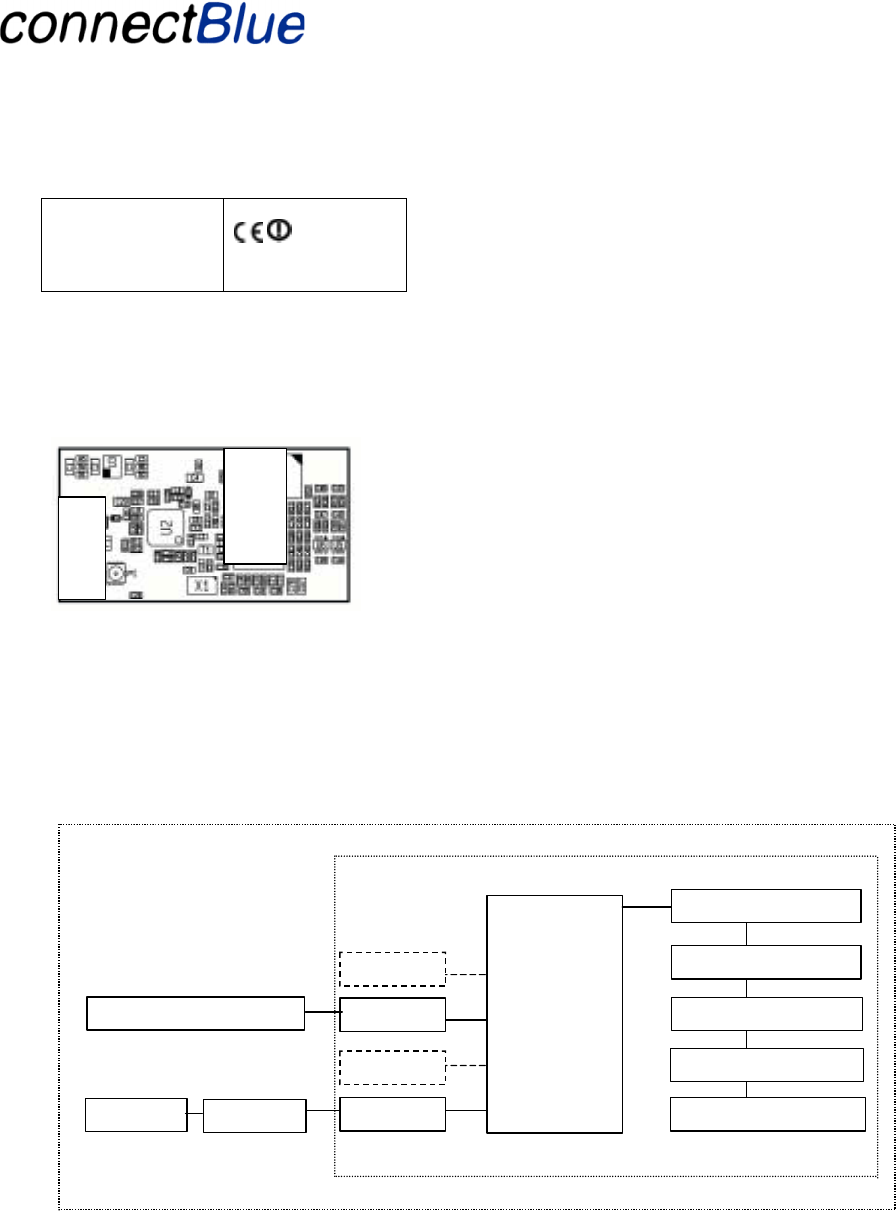
4.3 Bus Unit (Basic 2)
The Bus Unit communicates with the BT unit using an UART. The UART is used both for
management/diagnostics and IO data information.
CPU UART
Phoenix Bus Unit
BT unit
IO Host
Application
UART
PIO
I2C
AIO
HID
L2CAP
Link Mana
g
er
Baseband
BT Radio
I2C Memory Plug
Figure 8 - Displays the hardware configuration of the Bus Unit. The dashed lines are optional sections not
used in this configuration. The dotted lines describe the hardware separation line.
The I2C memory plug is used for configuration of the IO Units (see section 4.11.1).
Utfärdare / Issued by Datum / Date Beteckning / Ref. Sida / Page
Andreas Hörjel, Mats Andersson 2005-06-08 cBProject-0403-01 (23) 17 (61)
Ärende / Subjekt Godkänd av / Approved by
BT IO Functional Descri
p
tion
Template update: 00-12-01
4.3.1 UART Characteristics
Characteristic Value
Baud rate 115 200 bits/s
Character width 8 bits
# of stop bits 1
Parity Even
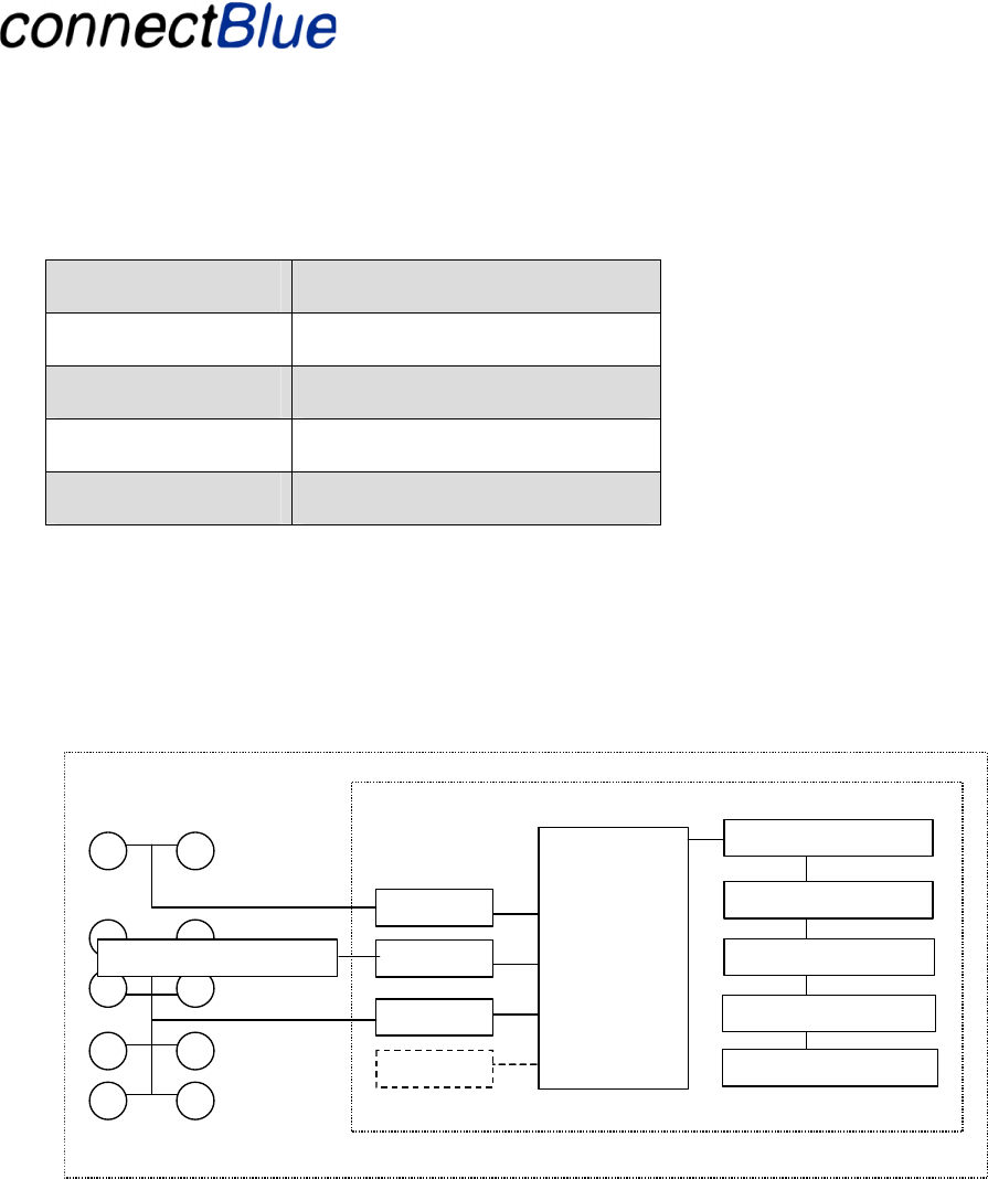
4.4 IO Unit (Basic 2)
The IO unit exists in two different hardware configurations.
4.4.1 Block IO
This configuration actuates and samples the IO and AIO, without the need for an external CPU.
Phoenix block IO
uni
t
BT unit
IO Host
Application
UART
PIO
I2C
AIO
HID
L2CAP
Link Mana
g
er
Baseband
BT Radio
I2C Memory Plug
Figure 9 - Displays the hardware configuration of the Block IO Unit. The dashed lines are optional
sections not used in this configuration. The dotted lines describe the hardware separation line.
The I2C memory plug is used for configuration of the IO Units (see section 4.11.1).
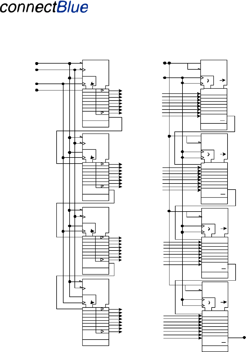
4.4.1.1 Digital IO Shift Register
The digital IOs for block IO are used for driving shift registers in order to expand the number of
digital inputs and outputs. An example hardware solution is described below (not part of this project).
Utfärdare / Issued by Datum / Date Beteckning / Ref. Sida / Page
Andreas Hörjel, Mats Andersson 2005-06-08 cBProject-0403-01 (23) 18 (61)
Ärende / Subjekt Godkänd av / Approved by
BT IO Functional Descri
p
tion
Template update: 00-12-01
out_32
out_31
out_30
out_29
out_28
out_27
out_26
out_25
R3
C2
power
1D
2D 3
R
C1
2D 3
R3
C2
power
1D
2D 3
R
C1
2D 3
R3
C2
power
1D
2D 3
R
C1
2D 3out_24
out_23
out_22
out_21
out_20
out_19
out_18
out_17
out_16
out_15
out_14
out_13
out_12
out_11
out_10
out_09
lacth_in
reset
latch_out
clk
data_out
data_in
in_32
in_31
in_30
in_29
in_28
in_27
in_26
in_25
G1(SHIFT )
G2(LOAD)
power
CLK1
CLK2
1C3 /
QH
QH
G1(SHIFT )
G2(LOA D)
power
CLK1
CLK2
1C3 /
QH
QH
G1(SHIFT )
G2(LOA D)
power
CLK1
CLK2
1C3 /
QH
QH
clk
ser
ser
in_24
in_23
in_22
in_21
in_20
in_19
in_18
in_17
in_08
in_07
in_06
in_05
in_04
in_03
in_02
in_01
R3
C2
power
1D
2D 3
R
C1
2D 3 out_08
out_07
out_06
out_05
out_04
out_03
out_02
out_01
G1(SHIFT )
G2(LOA D)
power
CLK1
CLK2
1C3 /
QH
QH
in_16
in_15
in_14
in_13
in_12
in_11
in_10
in_09
Figure 10 - An example of a shift register implementation

Utfärdare / Issued by Datum / Date Beteckning / Ref. Sida / Page
Andreas Hörjel, Mats Andersson 2005-06-08 cBProject-0403-01 (23) 19 (61)
Ärende / Subjekt Godkänd av / Approved by
BT IO Functional Descri
p
tion
Template update: 00-12-01
This solution has the following pin assignment:
PIO nr PIO name PIO properties
DigIO-0 Clk 10MHz output
DigIO-1 Data_out 10 Mhz output
DigIO-2 Data_in 10 MHz input
DigIO-3 Reset Output
DigIO-7 Latch_in Output
DigIO-8 Latch_out Output
The PIO properties are given to fit the IO unit’s possibilities to drive the PIO pins. This is especially
important to notice if the signals shall be isolated using opto couplers. The 10 MHz value is an
estimated value.
4.4.1.2 Digital IO – Filtering
A simple filtering is used for the digital IOs. The same value must be detected in two (2) consecutive
readings for the value to be considered as valid.
4.4.1.3 Analog - IO Precision
The analog IO precision is 12 bits.
4.4.1.4 Analog IO – Anti-aliasing filter requirements
The preliminary sampling rate is 16 kHz. This means there is a need to have a filter (externally from
the Bluetooth Units) that filters away components with higher sampling frequency than the sampling
rate divided by 2 and with the required signal/noise ratio.
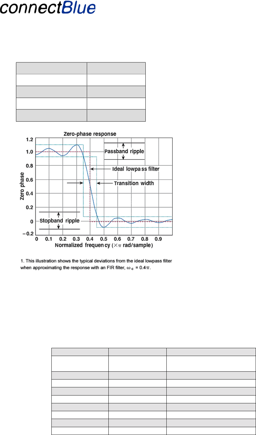
4.4.1.5 Analog IO - Input Filter
This section describes how the analog inputs of the Block IO shall be filtered. The outputs are set
without any filtering. As described the BTIO units contains a DSP. This DSP can and be used for
digital filtering of the input signal.
Possible filter is a low pass Finite Impulse Response filter (FIR). The IO Unit can send an update of
the analogue input with a frequency off 200 Hz, according to the HID sniff interval. However the
DSP can sample the signal much faster, this will be done in order to get an accurate value.
The characteristics decided are:
Input filter
Sampling frequency >= 8Khz
Utfärdare / Issued by Datum / Date Beteckning / Ref. Sida / Page
Andreas Hörjel, Mats Andersson 2005-06-08 cBProject-0403-01 (23) 20 (61)
Ärende / Subjekt Godkänd av / Approved by
BT IO Functional Descri
p
tion
Template update: 00-12-01
Stop band ripple <= 0,05%
Pass band ripple <= 0,05%
Cut frequency 40 Hz
Phase delay
Transition width 10 µs
Figure 11 - FIR filter
4.4.1.6 Analog IO – PSKEYS for the analog calibration
The PC runs a calibration program with access to certain PSKeys. A PSKey is a variable stored in
flash, Persistent Store. These PSKeys is used to set the module in calibration mode, enables you to
read the ADC values and the set the digital value to the DAC. These PSKey are used when calibrating
the units.
NAME PSKey name Value
PS_TEST_AIO PSKEY_USR1 Calibration mode = 1 run
mode = 0
PS_VOUT PSKEY_USR2 0 - 0xFFFF
PS_VIN1 PSKEY_USR3 0 - 0xFFFF
PS_VIN2 PSKEY_USR4 0 - 0xFFFF
PS_IN1_OFF PSKEY_USR5 0 - 0xFFFF
PS_IN1_GAN PSKEY_USR6 0 - 0xFFFFFF
PS_IN2_OFF PSKEY_USR7 0 - 0xFFFF
PS_IN2_GAN PSKEY_USR8 0 - 0xFFFFFF
PS_OUT1_OFF PSKEY_USR9 0 - 0xFFFF
Utfärdare / Issued by Datum / Date Beteckning / Ref. Sida / Page
Andreas Hörjel, Mats Andersson 2005-06-08 cBProject-0403-01 (23) 21 (61)
Ärende / Subjekt Godkänd av / Approved by
BT IO Functional Descri
p
tion
Template update: 00-12-01
PS_OUT1_GAN PSKEY_USR10 0 - 0xFFFFFF
PS_OUT2_OFF PSKEY_USR11 0 - 0xFFFF
PS_OUT2_GAN PSKEY_USR12 0 - 0xFFFFFF
PS_TEST_AIO is used for setting the module in calibration mode or run mode. The module will start
in calibration mode if this PSKey is set to 1. PS_VOUT shall be used to set the digital value for the
DAC, both of them. PS_VIN1 gives the read value from the ADC 1 and PS_VIN2 for ADC 2. The
other PSKeys shall be used for when setting the new calibration for each ADC and DAC.
4.4.1.7 Gateway functionality (Gateway)
In this mode, two IO units operating in direct IO mode is interconnected as a pair. Digital Inputs are
mirrored to Digital Outputs of the other unit and the other way round. The same with the analog IOs,
they are mirrored in both directions.
4.4.2 Module IO
The module IO unit communicates with the BT unit using an UART. The UART is used both for
management/diagnostics and IO data information. The BT unit communicates (over Bluetooth) all IO
information and some of the management/diagnostics information to the Bus unit.
Phoenix module IO
Uni
t
BT unit
IO Host
Application
UART
PIO
I2C
AIO
UART CPU
HID
L2CAP
Link Mana
g
er
Baseban
d
BT Radio
I2C Memory Plug
Figure 12 - Displays the hardware configuration of the Module IO unit. The dashed lines are optional
sections not used in this configuration. The dotted lines describe the hardware separation line.
The I2C memory plug is used for configuration of the IO Units (see section 4.11.1).
4.4.2.1 UART characteristics
See section 4.3.1.

Utfärdare / Issued by Datum / Date Beteckning / Ref. Sida / Page
Andreas Hörjel, Mats Andersson 2005-06-08 cBProject-0403-01 (23) 22 (61)
Ärende / Subjekt Godkänd av / Approved by
BT IO Functional Descri
p
tion
Template update: 00-12-01
4.5 Common Bus and IO Unit functionality (Basic 2)
4.5.1 Link quality indication
The link quality measures the Bit Error Rate (BER) with following values. Between 0xff and 0xd7
each bit distance represents 0.00025 BER. Thus:
Link Quality Value
Dec Hex
BER %
255 0xff 0.0000
254 0xfe 0.0025
253 0xfd 0.0050
252 0xfc 0.0075
etc. until
215 0xd7 0.1000
Between 0xd6 and 0x5a each bit distance represents 0.08 BER. Thus:
Link Quality Value
Dec Hex
BER %
215 0xd7 0.1000
214 0xd6 0.1800
213 0xd5 0.2600
etc. until
Between 0x59 and 0x00 each bit distance represents 0.64% BER.
In general a BER between 0 and 0.1% is workable. When the link is broken the value will be set to 0.
The measurements are averaged, exponentially over a number of packages (between 5 and 20). In
order to minimize performance impact the value is updated once every 5 second.

Utfärdare / Issued by Datum / Date Beteckning / Ref. Sida / Page
Andreas Hörjel, Mats Andersson 2005-06-08 cBProject-0403-01 (23) 23 (61)
Ärende / Subjekt Godkänd av / Approved by
BT IO Functional Descri
p
tion
Template update: 00-12-01
PIO nr Description
AuxIO-0 Aux-signal used as digital Pulse Width Modulated
(PWM) output. Used to indicate the link quality
(value between 0-255). See below for a table of the
values.
The output are 4 values representing 25, 50, 75,
100% duty cycle respectively (for the BER values,
see the table above):
100% => BER value between 235-255
75% => BER value between 215-234
50% => BER value between 195 - 214
25% => BER value < 195.
4.5.2 Fail-safe mode indication
PIO nr Description
AuxIO-2 Aux-signal used as digital IO. Active indicates that
the unit is in fail-safe mode.
4.5.3 Auto Pairing
Auto Pairing is used as method to pair two devices in a single-point configuration (see section 4.9 for
the different supported configurations). This method is only usable when the I2C plug not is
detected, see section 4.6.
Three PIOs are used to support this:
PIO nr Description
DigIO-6 Input pin to set the unit in pairable/pairing mode
respectively. The IO-unit is set to pairable and bus
unit to pairing mode.
NOTE! This pin is has two usages. This use and used
as a write-protect pin when the I2C-plug is detected
(see section 4.6).
Aux-IO-1 GREEN. The same LED as the GREEN LED used as
I2C-indicator (see section 4.6). Will be set to Active
at a successful pairing and not active at an un-
successful pairing.

Utfärdare / Issued by Datum / Date Beteckning / Ref. Sida / Page
Andreas Hörjel, Mats Andersson 2005-06-08 cBProject-0403-01 (23) 24 (61)
Ärende / Subjekt Godkänd av / Approved by
BT IO Functional Descri
p
tion
Template update: 00-12-01
DigIO-9 RED. The same LED as the RED LED used as I2C-
indicator (see section 4.6). Will be set to not active at
a successful pairing and active at an un-successful
pairing.
4.6 I2C Memory Plug (Basic 2)
This is a I2C connected memory. This unit is used to store information needed to set-up the virtual
cable between the IO unit and the bus unit. It contains:
• Bus Unit Bluetooth address.
• Bus Unit Passkey
• Bus Position of the IO unit using the plug (I2C Management)
4.6.1 Functionality of the plug
The plug is used to identify the Bus Unit for an IO Unit. When an IO Unit is powered on the
Bluetooth address and passkey is read and used to be able to connect to the Bus Unit.
The I2C plug has always the I2C member address '1010000'. (I2C Management)
When the plug is placed in the Bus Unit the Bluetooth Address and the passkey of the Bus Unit is
written to the plug. A default Bus Position of 1 is written to the plug and an I2C Plug detection
message is sent to the host (if it is a host based system). When a “Set Bus Position Request”
management message is received the bus position contained in the message is written to the plug and
the associated response message is sent to the host. For more on the messages used see chapter 4.10.
(I2C Management)
The I2C Memory Plug is not developed as a part of this project..
4.6.2 User interface
The BT units detects if there is a unit present on the I2C bus by using the electrical characteristics of
the I2C bus. This is done by looking at DIGIO-4 and DIGIO-5 PIO signals. If both are active the I2C
Plug is considered as present.
Two of the BT Unit PIO pins are used as user interface LEDs on the IO motherboard. These pins are
called Green and Red. Pin assignment:
PIO nr PIO name
DigIO-9 RED
AuxIO-1 GREEN
The following behaviour:

Utfärdare / Issued by Datum / Date Beteckning / Ref. Sida / Page
Andreas Hörjel, Mats Andersson 2005-06-08 cBProject-0403-01 (23) 25 (61)
Ärende / Subjekt Godkänd av / Approved by
BT IO Functional Descri
p
tion
Template update: 00-12-01
Unit Indicates RED pin GREEN pin
Bus Unit Not connected Not Active Not Active
Connected Not Active Active
Connected and a
successful write operation Active Active
Connected and a
unsuccessful write
operation
Active Not Active
IO Unit Not connected Not Active Not Active
Connected Active Active
Connected and successful
read operation Not Active Active
Connected and
unsuccessful read. Active Not Active
4.7 IO Unit Configuration
4.7.1 Mode
The IO Unit can operate in two modes (see section 4.4 for the different HW configurations).:
1. Sending IO data to and from a host over the UART. Later called UART mode. (Basic 2).
This is used for the Modular IO units.
2. Receiving IO data directly on the analogue and digital inputs of the module. Later called
direct IO mode. (Basic 1) This is used for block IO units.
Each mode is configured using different firmware versions.
4.7.2 IO Type (Basic 2)
BT Unit handles IO type only (32-bits digital input and output + 2 analog in and 2 analog out).
When used in a gateway configuration the inputs are mirrored to the outputs and vice versa. This
configuration handled by using two different FW versions (Gateway).
4.7.3 Tool Type (Robot)
For use on robots the tool type needs to be configured when the IO unit is mounted on a tool.
How to configure the Tool Type will be determined later in the project.

Utfärdare / Issued by Datum / Date Beteckning / Ref. Sida / Page
Andreas Hörjel, Mats Andersson 2005-06-08 cBProject-0403-01 (23) 26 (61)
Ärende / Subjekt Godkänd av / Approved by
BT IO Functional Descri
p
tion
Template update: 00-12-01
4.8 Bus Unit Configuration (Basic 1)
The Bus Unit always operates using the UART to communicate to the host. The configuration of the
associated IO units may be read using diagnostics messages (see section 4.10).
4.9 Configuration Management (Basic 2)
In general the will one firmware file for each type of configuration. The following configuration is
available:
Name Description
Host Unit P-to-P Host Unit FW used in a point-to-point
configuration. Supports I2C Memory Plug as well
as Auto Pairing.
Host Unit Multipoint Host Unit used in a multipoint configuration.
Supports I2C Memory Plug only.
IO unit Direct IO IO unit used in direct IO mode. Used for Block IO
units. Supports I2C Memory Plug as well as Auto
Pairing.
IO unit UART
mode. IO unit used in a UART mode. Used for Module IO
systems. Supports I2C Memory Plug as well as
Auto Pairing.
IO unit GW Direct
IO IO unit using direct IO mode but is used as the
Master of a GW pair. Always used in combination
with one “IO Unit Direct IO” unit (Gateway).
Supports I2C Memory Plug as well as Auto Pairing.

Utfärdare / Issued by Datum / Date Beteckning / Ref. Sida / Page
Andreas Hörjel, Mats Andersson 2005-06-08 cBProject-0403-01 (23) 27 (61)
Ärende / Subjekt Godkänd av / Approved by
BT IO Functional Descri
p
tion
Template update: 00-12-01
4.10 Additional PSKeys
4.10.1 Output Power Control
To support different antennas with higher gains there is a possibility to set the max output power of
the unit (see section 4.2.4 for more info about the antennas used). This is done by modifying the
following PSKey value:
PSKEY_LC_MAX_TX_POWER
The value is given in dBm steps. The recommended values are (corresponds to the values in the
automatic power control table used by the module to automatically adjust the output power):
16, 12, 8 … 0 dBm (in 4dB steps).
Note! The value set is automatically adjusted to the closest smaller value in the power table. This
means that the highest possible output value to use is 16 dBm.
Use the CSR Test API or the CSR tools to modify this value.
4.10.2 Bluetooth Name
The Bluetooth Name of the device may be changed by modifying the PSKey with the following
name:
PSKEY_DEVICE_NAME
The name is stored in arrays of uint16s, the name is packed in this pskey, two octets per uint16.
Working from start of the device's name, the first character is stored in the lower octet of the pskey's
first uint16, the second character in the upper octet of the first uint16, etc. If the name is an odd
number of characters then the upper octet of the last uint16 is '\0'.
The Bluetooth name has maximum length of 8 characters (to support the diagnostics messages, see
section 4.11).
4.11 Diagnostics and Management Protocol
(Step 2)(Diagnostics)
This section describes the diagnostic and management protocol for the BT IO. The diagnostics and
management data is acquired using a message-based protocol over UART. The protocol is described
below.
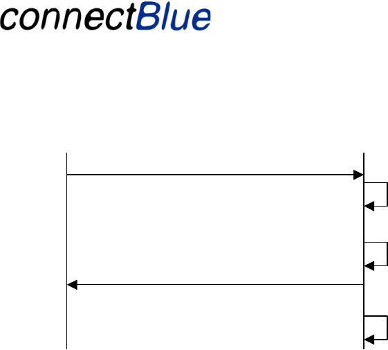
The configuration/diagnostics protocol in a request and response manner. A Host request
configuration/diagnostic data by sending a specific request. The Host waits until a response is
received. The response holds the requested information.
Utfärdare / Issued by Datum / Date Beteckning / Ref. Sida / Page
Andreas Hörjel, Mats Andersson 2005-06-08 cBProject-0403-01 (23) 28 (61)
Ärende / Subjekt Godkänd av / Approved by
BT IO Functional Descri
p
tion
Template update: 00-12-01
BT IO Unit
Host CPU Request
Response
Connect data
connection
Disconnect data
connection
Get
configuration/diagnostic
data
Figure 13 - Displays how messages are sent and received when acquiring configuration/diagnostics
information from the BT IO. All messages are sent/received using the UART.
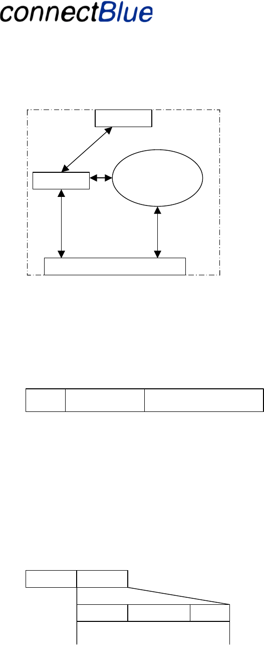
The message-based protocol works by filtering out all configuration/diagnostics messages from the
UART. The filter decides whether it has received a data message or a configuration/diagnostics
message. Data messages are directly routed to the corresponding IO unit. Configuration messages are
routed to the application code on the Bus unit. The BT IO unit performs the following on reception of
a configuration/diagnostics message.
1. The Bus unit disconnects the data connection on reception of a configuration message.
2. The BT IO creates a response package with the requested data. If a request requires
information from a remote IO unit it will use the HID control channel, (GET_REPORT) with
a certain report identifier, to acquire the requested information.
3. The BT IO returns the response.
4. The data pipe is reconnected when the configuration session is finished.
Utfärdare / Issued by Datum / Date Beteckning / Ref. Sida / Page
Andreas Hörjel, Mats Andersson 2005-06-08 cBProject-0403-01 (23) 29 (61)
Ärende / Subjekt Godkänd av / Approved by
BT IO Functional Descri
p
tion
Template update: 00-12-01
Bus Unit
Conf.data
Application
Filter
Data
UART
Conf
Bluetooth to IO unit
Figure 14 - Displays how configuration messages are routed in a Bus unit.
4.11.1 Management and Diagnostics messages
The protocol defines telegrams in format defined below. The telegrams start with a STX character
and a channel identifier, which is used for multiplexing multiple IO units. The second part of the
telegram is a basic HID packet, which contents depend on the purpose.
Channel Id HID control packet STX
The HID telegrams contents are described in HID specification version 1.0 [1]. A short description of
the telegrams used is described below.
Note! Management and Diagnostics messages for the Robot option are not fully described in this
document. Will be done when it are to be implemented.
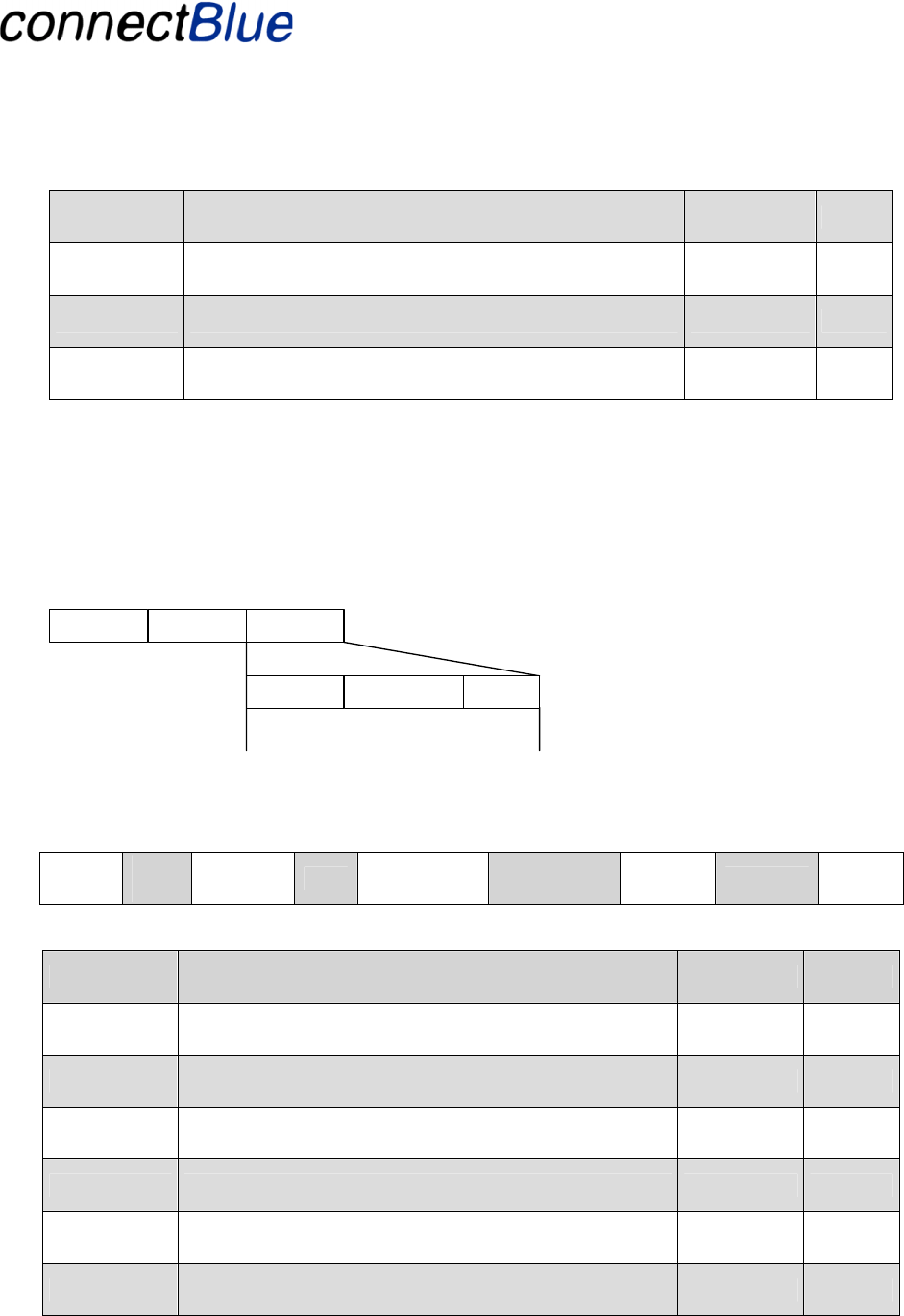
4.11.1.1 Management and Diagnostics request package
This package is for sending diagnostics and configuration parameters to the BT IO. The header is
always 0x43. Id identifies which paramter to return, the parameter field is a sub specification field to
specify certain data pointed to by Id. The message is always 13 bytes long, none used fields should be
set to 0x00. The last byte is a LRC of the complete message.
Header Payload
Id Parameters LRC

Utfärdare / Issued by Datum / Date Beteckning / Ref. Sida / Page
Andreas Hörjel, Mats Andersson 2005-06-08 cBProject-0403-01 (23) 30 (61)
Ärende / Subjekt Godkänd av / Approved by
BT IO Functional Descri
p
tion
Template update: 00-12-01
4.11.1.1.1 Bluetooth device address request
This request is for reading the Bluetooth address of a unit.
ST
X Ch
Id Header Id Byte4 Byte5
.......... Byte12 LRC
Name Description Value Byt
e
STX STX Character 0x02 0
Channel Id Identifies the end point. The value of 0x00 identifies the
Bus unit. The value of 0x01-0x07 identifies an IO unit. 0x00-0x07 1
Header Is always 0x43 for configuration/diagnostics request. 0x43 2
Id 0x81 specifies that a unit’s Bluetooth address shall be
read. 0x81 3
N.A Not used should all be set to 0x00. 0x00 4-12
LRC Calculated on bytes 2-12. 0xXX 13
4.11.1.1.2 Bluetooth device name request
This request is for reading a unit’s Bluetooth device name.
ST
X Ch
Id Header Id Byte4 Byte5
.......... Byte12 LRC
Name Description Value Byt
e
STX STX Character 0x02 0
Channel Id Identifies the end point. The value of 0x00 identifies the
Bus unit. The value of 0x01-0x07 identifies an IO unit. 0x00-0x07 1
Header Is always 0x43 for configuration/diagnostics request. 0x43 2
Id 0x82 specifies that a unit’s Bluetooth device name shall
be read. 0x82 3
N.A Not used should all be set to 0x00. 0x00 4-12
LRC Calculated on bytes 2-12. 0xXX 13
4.11.1.1.3 IO unit operating mode request

Utfärdare / Issued by Datum / Date Beteckning / Ref. Sida / Page
Andreas Hörjel, Mats Andersson 2005-06-08 cBProject-0403-01 (23) 31 (61)
Ärende / Subjekt Godkänd av / Approved by
BT IO Functional Descri
p
tion
Template update: 00-12-01
This request is for reading the operating mode of a unit.
ST
X Ch
Id Header Id Byte4 Byte5
.......... Byte12 LRC
Name Description Value Byt
e
STX STX character 0x02 0
Channel Id Identifies the end point. The value of 0x01-0x07
identifies an IO unit. 0x01-0x07 1
Header Is always 0x43 for configuration/diagnostics request. 0x43 2
Id 0x83 specifies that the operating mode shall be read. 0x83 3
N.A Not used should all be set to 0x00. 0x00 4-12
LRC Calculated on bytes 2-12. 0xXX 13
4.11.1.1.4 IO unit connection status request
This request is for reading the connection status of a unit.
ST
X Ch
Id Header Id Byte4 Byte5
.......... Byte12 LRC
Name Description Value Byte
STX STX Character 0x02 0
Channel Id Identifies the end point. The value of 0x01-0x07
identifies an IO unit. 0x01-0x07 1
Header Is always 0x43 for configuration/diagnostics request. 0x43 2
Id 0x84 specifies that the connection status shall be read. 0x84 3
N.A Not used should all be set to 0x00. 0x00 4-12
LRC Calculated on bytes 2-12. 0xXX 13
4.11.1.1.5 Set associated IO unit fail-safe mode request (Basic 2)

Utfärdare / Issued by Datum / Date Beteckning / Ref. Sida / Page
Andreas Hörjel, Mats Andersson 2005-06-08 cBProject-0403-01 (23) 32 (61)
Ärende / Subjekt Godkänd av / Approved by
BT IO Functional Descri
p
tion
Template update: 00-12-01
This request is for setting the fail-safe mode of an IO unit associated with the Bus unit.
ST
X Ch
Id Header Id Byte4 Byte5
.......... Byte12 LRC
Name Description Value Byt
e
STX STX character 0x02 0
Channel Id Identifies the end point. The value of 0x00 identifies the
Bus unit. The value of 0x01-0x07 identifies an IO unit. 0x00-0x07 1
Header Is always 0x43 for configuration/diagnostics request. 0x43 2
Id 0x85 specifies that the fail-safe mode shall be set. 0x85 3
Failsafe
mode 0x00 is running mode and 0x01 is fail-safe mode 0x00-0x01 4
N.A Not used should all be set to 0x00. 0x00 5-12
LRC Calculated on bytes 2-12. 0xXX 13
4.11.1.1.6 Get associated IO unit fail-safe mode request
This request is for getting the fail-safe mode of an IO unit associated with the Bus unit.
ST
X Ch
Id Header Id Byte4 Byte5
.......... Byte12 LRC
Name Description Value Byt
e
STX STX Character 0x02 0
Channel Id Identifies the end point. The value of 0x00 identifies the
Bus unit. The value of 0x01-0x07 identifies an IO unit. 0x00-0x07 1
Header Is always 0x43 for configuration/diagnostics request. 0x43 2
Id 0x86 specifies that the fail-safe mode shall be read. 0x86 3
N.A Not used should all be set to 0x00. 0x00 4-12
LRC Calculated on bytes 2-12. 0xXX 13

Utfärdare / Issued by Datum / Date Beteckning / Ref. Sida / Page
Andreas Hörjel, Mats Andersson 2005-06-08 cBProject-0403-01 (23) 33 (61)
Ärende / Subjekt Godkänd av / Approved by
BT IO Functional Descri
p
tion
Template update: 00-12-01
4.11.1.1.7 Get associated IO unit channel identity request (Basic 2)
This request is for getting the channel identity off an IO unit associated with the Bus unit. The Bus
unit uses this message at first connection with a new IO unit internally. This message CANNOT be
sent by a host system communicating with the Bus unit.
Header Id Byte2 Byte3 .......... Byte10 LRC
Name Description Value Byt
e
Header Is always 0x43 for configuration/diagnostics request. 0x43 0
Id 0x87 specifies that the IO units channel identity shall be
read. 0x87 1
N.A Not used should all be set to 0x00. 0x00 2-10
LRC Calculated on bytes 0-11. 0xXX 11
4.11.1.1.8 Set number of associated IO units request (Basic 2)
This request is for setting the number of IO units that will try to connect to a Bus Unit. This is sent
initially from the host to the Bus Unit and can only be sent once. When all of the IO units has
connected the Bus Unit will leave connectable mode.
STX Header Id NoIO Byte4 .......... Byte12 LRC
Name Description Value Byt
e
STX STX Character 0x02 0
Channel Id Identifies the end point. The value of 0x00 identifies the
Bus unit. 0x00 1
Header Is always 0x43 for configuration/diagnostics request. 0x43 2
Id 0x88 specifies that this message is used to set number of
IO units. 0x88 3
NoIO Number of IO Units that will try to connect. 0x01-0x07 4

Utfärdare / Issued by Datum / Date Beteckning / Ref. Sida / Page
Andreas Hörjel, Mats Andersson 2005-06-08 cBProject-0403-01 (23) 34 (61)
Ärende / Subjekt Godkänd av / Approved by
BT IO Functional Descri
p
tion
Template update: 00-12-01
N.A Not used should all be set to 0x00. 0x00 5-12
LRC Calculated on bytes 2-12. 0xXX 13
4.11.1.1.9 Link quality request
This request is for reading of the Bluetooth link quality.
ST
X Ch
Id Header Id Byte4 Byte5
.......... Byte12 LRC
Name Description Value Byt
e
STX STX Character 0x02 0
Channel Id Identifies the end point. The value of 0x00 identifies the
Bus unit. 0x00 1
Header Is always 0x43 for configuration/diagnostics request. 0x43 2
Id 0x89 specifies that the link quality shall be read. 0x89 3
N.A Not used should all be set to 0x00. 0x00 4-12
LRC Calculated on bytes 2-12. 0xXX 13
4.11.1.1.10 RSSI request
This request is for reading of the RSSI value.
ST
X Ch
Id Header Id Byte4 Byte5
.......... Byte12 LRC
Name Description Value Byt
e
STX STX Character 0x02 0
Channel Id Identifies the end point. The value of 0x00 identifies the
Bus unit. 0x00 1
Header Is always 0x43 for configuration/diagnostics request. 0x43 2
Id 0x8A specifies that RSSI value shall be read. 0x8A 3

Utfärdare / Issued by Datum / Date Beteckning / Ref. Sida / Page
Andreas Hörjel, Mats Andersson 2005-06-08 cBProject-0403-01 (23) 35 (61)
Ärende / Subjekt Godkänd av / Approved by
BT IO Functional Descri
p
tion
Template update: 00-12-01
N.A Not used should all be set to 0x00. 0x00 4-12
LRC Calculated on bytes 2-12. 0xXX 13
4.11.1.1.11 Bluetooth passkey request
This request is for reading the Bluetooth passkey for a unit.
ST
X Ch
Id Header Id Byte4 Byte5
.......... Byte12 LRC
Name Description Value Byt
e
STX STX Character 0x02 0
Channel Id Identifies the end point. The value of 0x00 identifies the
Bus unit. The value of 0x01-0x07 identifies an IO unit. 0x00-0x07 1
Header Is always 0x43 for configuration/diagnostics request. 0x43 2
Id 0x8B specifies that a unit’s Bluetooth passkey shall be
read. 0x8B 3
N.A Not used should all be set to 0x00. 0x00 4-12
LRC Calculated on bytes 2-12. 0xXX 13
4.11.1.1.12 Set Bus Position request (I2C Management)
This request is for writing the Bus Position into the I2C plug currently connected to the Bus Unit.
STX Header Id Bus
Positio
n Byte4 .......... Byte12 LRC
Name Description Value Byt
e
STX STX Character 0x02 0
Channel Id Identifies the end point. The value of 0x00 identifies the
Bus unit. 0x00 1
Header Is always 0x43 for configuration/diagnostics request. 0x43 2
Utfärdare / Issued by Datum / Date Beteckning / Ref. Sida / Page
Andreas Hörjel, Mats Andersson 2005-06-08 cBProject-0403-01 (23) 36 (61)
Ärende / Subjekt Godkänd av / Approved by
BT IO Functional Descri
p
tion
Template update: 00-12-01
Id 0x8C specifies that this message is used to set number of
IO units. 0x8C 3
Bus
Position Bus Position associated with the current I2C plug 0x01-0x07 4
N.A Not used should all be set to 0x00. 0x00 5-12
LRC Calculated on bytes 2-12. 0xXX 13
4.11.1.2 Management and Diagnostics response package
This package is returned in response to a diagnostics or configuration request . The header is always
0xA3. Id identifies which parameter that is returned. The parameter field holds the requested
parameter. The size of a respones is fixed to 14 bytes. Bytes with no data should be set to 0x00. The
last byte is a LRC off the complete message.
Header Payload
Id Parameter LRC
STX
4.11.1.2.1 Bluetooth device address response
This message is returned in response to the Bluetooth device address request.
ST
X Ch
Id Header Id BT_Addr
0 BT_Addr
1
.......... Byte12 LRC
Name Description Value Byte
STX STX Character 0x02 0
Channel Id Identifies the source. The value of 0x00 identifies the
Bus unit. The value of 0x01-0x07 identifies an IO unit. 0x00-0x07 1
Header Is always 0xA3 for configuration/diagnostics data
response. 0xA3 2
Id 0x81 specifies that a Bluetooth address shall be read. 0x81 3
BT_Addr0 MSB of the Bluetooth address. 4
BT_Addr1 5

Utfärdare / Issued by Datum / Date Beteckning / Ref. Sida / Page
Andreas Hörjel, Mats Andersson 2005-06-08 cBProject-0403-01 (23) 37 (61)
Ärende / Subjekt Godkänd av / Approved by
BT IO Functional Descri
p
tion
Template update: 00-12-01
BT_Addr2 6
BT_Addr3 7
BT_Addr4 8
BT_Addr5 LSB of the Bluetooth address. 9
N.A Not used should all be set to 0x00. 10-12
LRC Calculated on bytes 2-12. 0xXX 13
A Bluetooth address of 008037112233 is represented a follows in BT_Addr0 - BT_Addr5.
BT_Addr0 0x00
BT_Addr1 0x80
BT_Addr2 0x37
BT_Addr3 0x11
BT_Addr4 0x22
BT_Addr5 0x33
4.11.1.2.2 Bluetooth device name response
This message is returned in response to the Bluetooth device name request.
ST
X Ch
Id Header Id Name0 Name1
.......... Name8 LRC
Name Description Value Byt
e
STX STX Character 0x02 0
Channel Id Identifies the source. The value of 0x00 identifies the
Bus unit. The value of 0x01-0x07 identifies an IO unit. 0x00-0x07 1
Header Is always 0xA3 for configuration/diagnostics data
response. 0xA3 2
Id 0x82 specifies that a unit’s Bluetooth device name have
been read. 0x82 3

Utfärdare / Issued by Datum / Date Beteckning / Ref. Sida / Page
Andreas Hörjel, Mats Andersson 2005-06-08 cBProject-0403-01 (23) 38 (61)
Ärende / Subjekt Godkänd av / Approved by
BT IO Functional Descri
p
tion
Template update: 00-12-01
Name0-8 Local name string. Remaining bytes shall be set to 0x00
if name is shorter. 0xXX 4-12
LRC Calculated on bytes 2-12. 0xXX 13
4.11.1.2.3 IO unit operating mode response
This message is returned in response to the operating mode of an IO unit request.
STX Ch
Id Header Id Oper
mode Byte5
.... Byte12 LRC
Name Description Value Byt
e
STX STX Character 0x02 0
Channel Id Specifies the source. The value of 0x01-0x07 identifies
an IO unit. 0x01-0x07 1
Header Is always 0xA3 for configuration/diagnostics data
response. 0xA3 2
Id 0x83 specifies that the operating mode have been read. 0x83 3
Oper mode 0x01 is for UART mode and 0x02 is for IO mode. 0x01-0x02 4
N.A Not used should all be set to 0x00. 0x00 5-12
LRC Calculated on bytes 2-12. 0xXX 13
4.11.1.2.4 IO unit connection status response
This message is returned in response to the connection status request.
ST
X Ch Id Header Id Con
stat Byte 5
......... Byte12 LRC
Name Description Value Byt
e
STX STX Character 0x02 0
Channel Id Specifies the source. The value of 0x01-0x07 identifies
an IO unit. 0x01-0x07 1

Utfärdare / Issued by Datum / Date Beteckning / Ref. Sida / Page
Andreas Hörjel, Mats Andersson 2005-06-08 cBProject-0403-01 (23) 39 (61)
Ärende / Subjekt Godkänd av / Approved by
BT IO Functional Descri
p
tion
Template update: 00-12-01
Header Is always 0xA3 for configuration/diagnostics data
response. 0xA3 2
Id 0x84 specifies that the connection status have been read. 0x84 3
Con stat Specifies the connection status of an IO unit. 0x00 is
disconnected and 0x01 is connected. 0x00-0x01 4
N.A Not used should all be set to 0x00. 0x00 5-12
LRC Calculated on bytes 2-12. 0xXX 13
4.11.1.2.5 Set associated IO unit fail-safe mode response
This message is returned in response to the set the fail-safe mode of an IO unit request.
ST
X Ch
Id Header Id Failsafe
mode Byte5
.......... Byte12 LRC
Name Description Value Byt
e
STX STX Character 0x02 0
Channel Id Identifies the end point. The value of 0x00 identifies the
Bus unit. 0x01-0x07 1
Header Is always 0xA3 for configuration/diagnostics data
response. 0xA3 2
Id 0x85 identifies that an IO unit’s fail-safe mode has been
set. 0x85 3
Failsafe
mode Specifies if the command was properly executed. 0x00 =
running mode and 0x01 = failsafe mode. 0x00-0x01 4
N.A Not used should all be set to 0x00. 0x00 5-12
LRC Calculated on bytes 2-12. 0xXX 13
4.11.1.2.6 Get associated IO unit fail-safe mode response
This message is returned in response to the get the fail-safe mode request.
ST
X Ch
Id Header Id Failsaf
e
mode Byte5
.......... Byte12 LRC

Utfärdare / Issued by Datum / Date Beteckning / Ref. Sida / Page
Andreas Hörjel, Mats Andersson 2005-06-08 cBProject-0403-01 (23) 40 (61)
Ärende / Subjekt Godkänd av / Approved by
BT IO Functional Descri
p
tion
Template update: 00-12-01
Name Description Value Byt
e
STX STX Character 0x02 0
Channel Id Identifies the end point. The value of 0x00 identifies the
Bus unit. 0x01-0x07 1
Header Is always 0xA3 for configuration/diagnostics data
response. 0xA3 2
Id 0x86 identifies that a remote Bluetooth address shall be
read. 0x86 3
Failsafe
mode Specifies the fail-safe mode status that has been read.
0x00 = running mode and 0x01 = failsafe mode. 0x00-0x01 4
N.A Not used should all be set to 0x00. 0x00 5-12
LRC Calculated on bytes 2-12. 0xXX 13
4.11.1.2.7 Get IO unit channel identity response (Basic 2)
This message is returned in response to the get channel identity request. This is a response that is
used internally by the Bus unit. This response shall never be sent from the Bus unit.
Header Id Ch Id Byte 3 ............ Byte10 LRC
Name Description Value Byt
e
Header Is always 0xA3 for configuration/diagnostics data
response. 0xA3 0
Id 0x87 identifies that this is a response to reading of the
channel identifier. 0x87 1
Ch Id The channel identifier for this IO unit 0x01-0x07 2
N.A Not used should all be set to 0x00. 0x00 3-10
LRC Calculated on bytes 1-11. 0xXX 11
4.11.1.2.8 Set number of associated IO units response (Basic 2)
This message is returned in response to the set the number of IO units message.
STX Ch Id Header Id NoIO Byte5
.......... Byte12 LRC

Utfärdare / Issued by Datum / Date Beteckning / Ref. Sida / Page
Andreas Hörjel, Mats Andersson 2005-06-08 cBProject-0403-01 (23) 41 (61)
Ärende / Subjekt Godkänd av / Approved by
BT IO Functional Descri
p
tion
Template update: 00-12-01
Name Description Value Byt
e
STX STX Character 0x02 0
Channel Id Identifies the end point. The value of 0x00 identifies the
Bus unit. 0x00 1
Header Is always 0xA3 for configuration/diagnostics response. 0xA3 2
Id 0x88 specifies that this is a response to a setting of
maximum number of connecting IO units. 0x88 3
NoIO Number of IO Units that will try to connect. 0x00-0x07 4
N.A Not used should all be set to 0x00. 0x00 5-12
LRC Calculated on bytes 2-12. 0xXX 13
4.11.1.2.9 Link quality response
This message is returned in response to the link quality request.
ST
X Ch
Id Header Id Quality Byte4
.......... Byte11 LRC
Name Description Value Byt
e
STX STX Character 0x02 0
Channel Id Identifies the source. The value of 0x00 identifies the
Bus unit. 0x00 1
Header Is always 0xA3 for configuration/diagnostics data
response. 0xA3 2
Id 0x89 specifies that the link quality has been read. 0x89 3
Quality Byte containing the link quality value (see section Link
quality indicationfor description of the meaning of the
value). 0xXX 4
N.A Not used should all be set to 0x00. 0x00 5-12
LRC Calculated on bytes 2-12. 0xXX 13

Utfärdare / Issued by Datum / Date Beteckning / Ref. Sida / Page
Andreas Hörjel, Mats Andersson 2005-06-08 cBProject-0403-01 (23) 42 (61)
Ärende / Subjekt Godkänd av / Approved by
BT IO Functional Descri
p
tion
Template update: 00-12-01
4.11.1.2.10 RSSI response
This message is returned in response to the link quality request.
ST
X Ch
Id Header Id RSSI
value Byte5
.......... Byte12 LRC
Name Description Value Byt
e
STX STX Character 0x02 0
Channel Id Identifies the source. The value of 0x00 identifies the
Bus unit. 0x00 1
Header Is always 0xA3 for configuration/diagnostics data
response. 0xA3 2
Id 0x8A specifies that the RSSI value have been read. 0x8A 3
Quality A signed 8-bit integer containing the RSSI value. See
reference 3 for more details about this value. 0xXX 4
N.A Not used should all be set to 0x00. 0x00 5-12
LRC Calculated on bytes 2-12. 0xXX 13
4.11.1.2.11 Bluetooth passkey response
This message is returned in response to the Bluetooth passkey request.
ST
X Ch
Id Header Id Passkey0 Passkey1
.......... Passkey8 LRC
Name Description Value Byt
e
STX STX Character 0x02 0
Channel Id Identifies the source. The value of 0x00 identifies the
Bus unit. The value of 0x01-0x07 identifies an IO unit. 0x00-0x07 1
Header Is always 0xA3 for configuration/diagnostics data
response. 0xA3 2
Id 0x8B specifies that a unit’s Bluetooth passkey have been
read. 0x8B 3
Passkey 1-8 Passkey string. Remaining bytes shall be set to 0x00 if
name is shorter. 0xXX 4-12

Utfärdare / Issued by Datum / Date Beteckning / Ref. Sida / Page
Andreas Hörjel, Mats Andersson 2005-06-08 cBProject-0403-01 (23) 43 (61)
Ärende / Subjekt Godkänd av / Approved by
BT IO Functional Descri
p
tion
Template update: 00-12-01
LRC Calculated on bytes 2-12. 0xXX 13
4.11.1.2.12 Set Bus Position response (I2C Management)
This message is returned in response to the Set Bus Position message.
STX Ch
Id Header Id Result Byte5
.......... Byte12 LRC
Name Description Value Byt
e
STX STX Character 0x02 0
Channel Id Identifies the end point. The value of 0x00 identifies the
Bus unit. 0x00 1
Header Is always 0xA3 for configuration/diagnostics response. 0xA3 2
Id 0x8C specifies that this is a response to a setting of
maximum number of connecting IO units. 0x8C 3
Result Result. 0x00 = Successful write operation, 0x01=Plug
bot available, 0x02 = Other write error. 0x00-0x02 4
N.A Not used should all be set to 0x00. 0x00 5-12
LRC Calculated on bytes 2-12. 0xXX 13
4.11.1.3 Management and Diagnostics Indication Package
This section describes the management and Diagnostics indication packages. They are built up in the
same way as the response/request packages. The only difference is that they are sent upon certain
events described below.
The header is always 0xA3. Id identifies which paramter that is returned. The parameter field holds
the indication parameter. The size of a indication is fixed to 13 bytes. Bytes with no data should be
set to 0x00. The last byte is a LRC off the complete message.
Header Payload
Id Parameter LRC
STX

Utfärdare / Issued by Datum / Date Beteckning / Ref. Sida / Page
Andreas Hörjel, Mats Andersson 2005-06-08 cBProject-0403-01 (23) 44 (61)
Ärende / Subjekt Godkänd av / Approved by
BT IO Functional Descri
p
tion
Template update: 00-12-01
4.11.1.3.1 Fail safe mode indication (Basic 2)
This message is sent from the Bus unit to the Host upon a detection of that the IO unit has entered
fail-safe mode.
STX Ch Id Header Id Byte 4 …. Byte 12 LRC
Name Description Value Byte
STX STX Character 0x02 0
Channel Id Identifies the source. The value of 0x00 identifies the
Bus unit. The value of 0x01-0x07 identifies an IO unit. 0x01-0x07 1
Header Is always 0xA3 for configuration/diagnostics data
indication. 0xA3 2
Id 0x8D specifies that failsafe mode enter indication. 0x8D 3
N.A Not used should all be set to 0x00. 4-12
LRC Calculated on bytes 2-12. 0xXX 13
4.11.1.3.2 I2C Plug Present Indication (I2C Management)
This message is sent from the Bus unit to the Host upon a detection of an I2C plug on the base unit.
STX Ch Id Header Id Byte 4 …. Byte 12 LRC
Name Description Value Byte
STX STX Character 0x02 0
Channel Id Identifies the source. The value of 0x00 identifies the
Bus unit (can only be received from the Bus Unit). 0x00 1
Header Is always 0xA3 for configuration/diagnostics data
indication. 0xA3 2
Id 0x8E specifies that I2C Plug Present indication. 0x8E 3
N.A Not used should all be set to 0x00. 4-12
LRC Calculated on bytes 2-12. 0xXX 13

Utfärdare / Issued by Datum / Date Beteckning / Ref. Sida / Page
Andreas Hörjel, Mats Andersson 2005-06-08 cBProject-0403-01 (23) 45 (61)
Ärende / Subjekt Godkänd av / Approved by
BT IO Functional Descri
p
tion
Template update: 00-12-01
4.11.2 LRC
The LRC field is one byte, containing an 8-bit binary value. The LRC value is calculated by the
transmitting device, which appends the LRC to the message. The receiving device calculates an LRC
during receipt of the message, and compares the calculated value to the actual value it received in the
LRC field. If the two values are not equal, an error results.
The LRC is calculated by adding together successive 8-bit bytes of the message, discarding any carries,
and then two’s complementing the result. The LRC is calculated on the complete message excluding the
channel identifier.
4.12 Data Communication between the host and the Bus unit
(Basic 2)
This data communication is used for setting/receiving data to/from the Bus units associated IO units.
The protocol is defined in the following sections.
4.12.1 Data messages
The telegrams start with a channel identifier, which is used for multiplexing multiple IO units. The
second part of the telegram is a basic HID data packet, which contents depend on the purpose.
Channel Id HID data packet
The HID telegrams contents are described in HID specification version 1.0 [1]. A short description of
the telegrams used is described below.
4.12.1.1 Data set package
This package is for writing AIO and PIO values to a BTIO unit. The header is always 0xA1. Id
identifies the contents of the data package.The parameter field is contains the data described by Id.
The message is always odd bytes long, none used fields should be set to 0x00. The last byte is a LRC
of the complete message. This request is send by the host to the bus unit when a set action is
requiered.
Header Payload
Id Parameters LRC

Utfärdare / Issued by Datum / Date Beteckning / Ref. Sida / Page
Andreas Hörjel, Mats Andersson 2005-06-08 cBProject-0403-01 (23) 46 (61)
Ärende / Subjekt Godkänd av / Approved by
BT IO Functional Descri
p
tion
Template update: 00-12-01
4.12.1.1.1 Data set package direct IO mode
This request is for setting the PIO and AIO values.
Ch Id Header Id Byte3 Byte4 .......... Byte11 LRC
Name Description Value Byte
Channel Id Identifies the end point. The value of 0x00 identifies the
Bus unit. The value of 0x01-0x07 identifies an IO unit. 0x01-
0x07 0
Header Is always 0xA2 for data packages. 0xA2 1
Id 0x05 specifies the data parameters as described below. 0x05 2
PIO 8-15 0xXX 3
PIO 0-7 0xXX 4
PIO 24-31 0xXX 5
PIO 16-23 0xXX 6
AIO 1 MSB AIO 1 most significant byte of the AIO word. 0xXX 7
AIO 1 LSB AIO 1 least significant byte of the AIO word. 0xXX 8
AIO 2 MSB AIO 2 most significant byte of the AIO word. 0xXX 9
AIO 2 LSB AIO 2 least significant byte of the AIO word. 0xXX 10
N.A Not used should all be set to 0x00. 0x00 11
LRC Calculated on bytes 1-11. 0xXX 12

Utfärdare / Issued by Datum / Date Beteckning / Ref. Sida / Page
Andreas Hörjel, Mats Andersson 2005-06-08 cBProject-0403-01 (23) 47 (61)
Ärende / Subjekt Godkänd av / Approved by
BT IO Functional Descri
p
tion
Template update: 00-12-01
4.12.1.1.2 Data set package UART mode
This request is for sending data to an IO Unit in UART mode.
Ch Id Header Id Byte3 Byte4 .......... Byte11 LRC
Name Description Value Byt
e
Channel Id Identifies the end point. The value of 0x00 identifies the
Bus unit. The value of 0x01-0x07 identifies an IO unit. 0x01-0x07 0
Header Is always 0xA2 for data packages. 0xA2 1
Id 0x06 specifies the data parameters as described below. 0x06 2
Data 0xXX 3-11
LRC Calculated on bytes 1-11. 0xXX 12
4.12.1.2 Data change package
This package is received when AIO and PIO values changes in a BTIO unit. The header is always
0xA1. Id identifies the contents of the data package.The parameter field contains the data described
by Id. The message is always odd bytes long, none used fields should be set to 0x00. The last byte is a
LRC of the complete message. This response is produced by the BTIO unit whenever a PIO and/or
AIO change is deteceted.
Header Payload
Id Parameters LRC

Utfärdare / Issued by Datum / Date Beteckning / Ref. Sida / Page
Andreas Hörjel, Mats Andersson 2005-06-08 cBProject-0403-01 (23) 48 (61)
Ärende / Subjekt Godkänd av / Approved by
BT IO Functional Descri
p
tion
Template update: 00-12-01
4.12.1.2.1 Data change package for direct IO mode
This response describes the PIO and AIO values.
Ch Id Header Id Byte3 Byte4 .......... Byte11 LRC
Name Description Value Byte
Channel Id Identifies the end point. The value of 0x00 identifies the
Bus unit. The value of 0x01-0x07 identifies an IO unit. 0x01-
0x07 0
Header Is always 0xA1 for data packages. 0xA1 1
Id 0x05 specifies the data parameters as described below. 0x05 2
PIO 8-15 0xXX 3
PIO 0-7 0xXX 4
PIO 24-31 0xXX 5
PIO 16-23 0xXX 6
AIO 1
MSB AIO 1 most significant byte of the AIO word. 0xXX 7
AIO 2 LSB AIO 2 least significant byte of the AIO word. 0xXX 8
AIO 2
MSB AIO 2 most significant byte of the AIO word. 0xXX 9
AIO 2 LSB AIO 2 least significant byte of the AIO word. 0xXX 10
N.A Not used should all be set to 0x00. 0x00 11
LRC Calculated on bytes 1-11. 0xXX 12
4.12.1.2.2 Data change package for UART mode
This response describes the PIO and AIO values.
Ch Id Header Id Byte3 Byte4 .......... Byte11 LRC
Name Description Value Byte

Utfärdare / Issued by Datum / Date Beteckning / Ref. Sida / Page
Andreas Hörjel, Mats Andersson 2005-06-08 cBProject-0403-01 (23) 49 (61)
Ärende / Subjekt Godkänd av / Approved by
BT IO Functional Descri
p
tion
Template update: 00-12-01
Channel Id Identifies the end point. The value of 0x00 identifies the
Bus unit. The value of 0x01-0x07 identifies an IO unit. 0x01-0x07 0
Header Is always 0xA1 for data packages. 0xA1 1
Id 0x06 specifies the data parameters as described below. 0x06 2
Data 0xXX 3-11
LRC Calculated on bytes 1-11. 0xXX 12
4.13 Data flow between the Bus Unit host and the BT Host
CPU
The Bus Unit Host CPU (called IBS later) communicates with BT Host CPU over a UART interface.
The messages are passed using a synchronous method (see Figure 15 below).
The figure shows an example with two IO units. Some comments to the figure (see markers in the
figure):
1. You send data to each of the x units one by one (how many depends on how many slaves you
have, in the example it is two). When a correct message is received two (no of bytes,
checksum etc. is checked) three situations may occur:
a. If the received message is data message the message will be forwarded to the
Bluetooth stack for transfer to the remote unit and latest received data message from
the remote unit will be passed back to the IBS.
b. As a response to a data message an indication message may be sent e.g. when an IO
unit enters fail-safe mode (see section 4.11.1.3.1).
c. If the received message is a diagnostics request package the BT Host unit will
directly start to threat this and reply with the corresponding response message.
If an incorrect message is received the BT unit will not respond. Timeout supervision is required
in the IBS (the timeout time needs to be decided later). When the timeout time has passed the
sequence is continued (it means that data will be sent the next time the BT Host unit is "polled").
2. Data set message is sent when the next sniff slot for addressed slave occurs. If more than one
message is received from IBS between two slots the oldest ones are disposed and latest is
used.
3. Date change messages arrive at the BT Host independent of when the IBS "polls" it. The BT
Host stores that latest received value and this is sent at the next time an IBS poll for this slave
arrives.

Utfärdare / Issued by Datum / Date Beteckning / Ref. Sida / Page
Andreas Hörjel, Mats Andersson 2005-06-08 cBProject-0403-01 (23) 50 (61)
Ärende / Subjekt Godkänd av / Approved by
BT IO Functional Descri
p
tion
Template update: 00-12-01
NOTE! At power up the Bus Unit will wait for an initial “Set number of associated IO units
request” message (see section 4.11.1.1.8). Before this message is received and responded to, the
Host unit will not respond to any messages from the IBS.
BT_Host BT_IO 1
IBS µP
0
1
2
3
4
5
6
7
8
9
10
11
12
13
14
15
16
17
BT_IO 2
DataSetCh1
18
19
20
21
22
23
24
25
26
27
28
ms
1 3
DataChangeCh1
DataSetCh2
DataChangeCh2
DataSetCh1
DataChangeCh1
DataSetCh1
DataChangeCh1
DataSetCh2
DataChangeCh2
DataSetCh1
DataChangeCh1
DataSetCh2
DataChangeCh2
2
Figure 15 - Synchronous Message Passing (time axis just for reference, not real values)

Utfärdare / Issued by Datum / Date Beteckning / Ref. Sida / Page
Andreas Hörjel, Mats Andersson 2005-06-08 cBProject-0403-01 (23) 51 (61)
Ärende / Subjekt Godkänd av / Approved by
BT IO Functional Descri
p
tion
Template update: 00-12-01
4.14 Connection Establishment (Basic 2)
The establishment of a Bluetooth connection between two devices is made at the set up phase of a
new system or at service. Once two devices have established a connection, these devices are paired
and will always connect to each other automatically.
4.14.1 Bus Unit initialisation (Basic 2)
The Bus Unit needs information about the number of IO Units that will connect. This is done by
configuration message “Set number of associated IO units request” (ID 0x8A). This message is sent
once after power up of the Bus Unit.
The Bus Unit will accept this number of IO units only. After the last unit is connected it will leave its
“connectable” mode. If an IO unit disconnects it will be set to “connectable” again.
The reasons for this are to optimise the use of the radio link. A “connectable” unit will reserve a
certain part of the radio bandwidth for listening for a connection.
4.14.2 Configuration of connection information - I2C Memory Plug
The IO Unit is configured to connect directly to the Bus Unit using the Bus Unit Bluetooth device
address and passkey. The address and passkey is transferred to the IO unit using a removable I2C
memory that the IO unit can access during start up. This memory contains the following information:
• The Bus Unit’s Bluetooth device address.
• The Bus Unit’s passkey.
The I2C Bus Member Address is used to identify the channel ID when used in a multipoint
configuration (see section 4.5).
The information is written into the I2C memory when placed on the Bus Unit. The IO Unit has the
same interface, which it uses to read the information at power up.
4.14.3 Connection Scheme
The BT unit connects to another BT unit using the connection scheme described below. The initiator
of the connection is the IO Unit and the connected is the Bus Unit.
The scheme is based around two start-up conditions, power up and wake up. Power up is when the
unit is powered up for the first time after a shut down. Wake up is when the unit goes from a sniff
mode with a long sniff period (100ms) to a short sniff period (5ms), from idle to being active
communicating data. Wake up mode can only be realised if the IO Unit is continuously powered
when idle, with batteries or a super cap.
Power up (Basic 2):
1. IO Unit: Reads the Bluetooth device address of the Bus unit using I2C memory device
connected to the IO.

Utfärdare / Issued by Datum / Date Beteckning / Ref. Sida / Page
Andreas Hörjel, Mats Andersson 2005-06-08 cBProject-0403-01 (23) 52 (61)
Ärende / Subjekt Godkänd av / Approved by
BT IO Functional Descri
p
tion
Template update: 00-12-01
2. IO Unit: If the IO unit is paired with the Bus unit it connects directly to the Bus Unit,
otherwise bonding is performed prior to connect.
Wake up (Robot):
1. IO Unit: The IO unit is woken from sniff mode and directly starts send IO data.
The IO unit reads the Bus Unit BD address and passkey and from an I2C memory placed on the IO
unit, see the configuration chapter. The channel identity is also read from the I2C memory; the
identity is later used by the Bus unit to multiplex IO units. The Bus unit reads this identity number
from the IO unit at start-up. The Bus unit uses the HID Control channel to read the identity from the
IO unit, see chapter 4.8.1.1.9 and 4.8.1.2.9 for specification off the used messages.
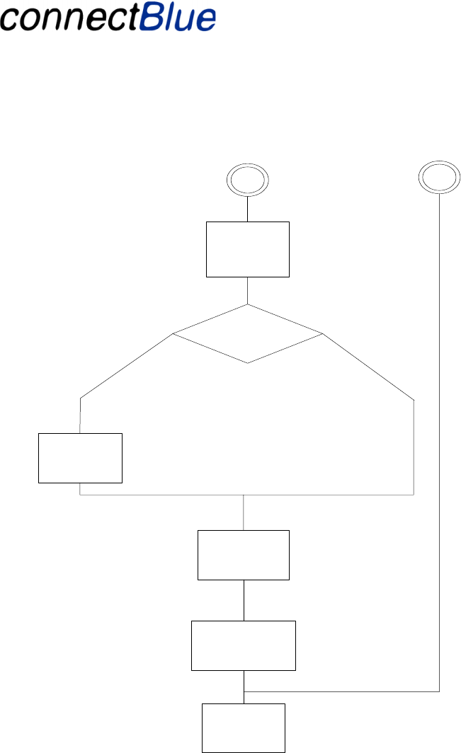
Utfärdare / Issued by Datum / Date Beteckning / Ref. Sida / Page
Andreas Hörjel, Mats Andersson 2005-06-08 cBProject-0403-01 (23) 53 (61)
Ärende / Subjekt Godkänd av / Approved by
BT IO Functional Descri
p
tion
Template update: 00-12-01
Power up (Basic 2)
IO unit:connects
to Base unti
Change parameter
between IO unit
and base station
(Duplex).
Communicatio
n process data
IO Unit Wake up (Robot)
IO unit: G et
robot identity
Bus unit Bd
address and
Pin code
IO unit: Is the IO unit
paired with the Bus unit
No Yes
Perform
bonding
Figure 16 - Displays the connection scheme for the BT unit.
4.14.4 Connection Time
The BT IO specifies two different connection scenarios with different connection times:
• Fast connection that occurs when the IO Unit is in wake up mode but not disconnected.
(Robot)
• Slow connection that occurs when the IO Unit is in power up mode. (Basic 2)

Utfärdare / Issued by Datum / Date Beteckning / Ref. Sida / Page
Andreas Hörjel, Mats Andersson 2005-06-08 cBProject-0403-01 (23) 54 (61)
Ärende / Subjekt Godkänd av / Approved by
BT IO Functional Descri
p
tion
Template update: 00-12-01
The fast connection mode is realized using sniff mode with a long sniff period (100ms). This means
that the IO Unit is synchronized to the Bus Unit, which enables fast activation into running mode and
communicating data. (Robot)
Connection mode Connection time [ms]1
Fast connection 100
Slow connection 3000
4.14.5 Disconnection (Robot)
The IO Unit will repeatedly be disconnected from the Bus Unit, i.e. when changing tools on the robot
or when maintenance is performed. The IO Unit has no external power source during this time, which
will force the power up mode when reconnecting. It is more optimal if the unit goes to wake up mode
on disconnection, which enables fast communication establishment when the IO Unit is reconnected.
The IO Unit can operate in wake up mode (sniff mode with long sniff period), still being
synchronized to the Bus Unit, when the IO is disconnected. Wake up mode uses a longer sniff period;
a long sniff period (100ms) consumes less power than a short sniff period (5ms), than when the
communication is running. Wake up mode allows the IO Unit to quickly be reactivated in the Bus
Unit’s piconet due to that it is synchronized with the Bus Unit, however it demands some kind of
power source. This can is realized with batteries or a super cap mounted on the IO Unit.
The IO Unit will restart from power up mode when no super cap or battery power source is present.
4.15 Security (Basic 2)
The Bluetooth communication link is protected by Bluetooth’s security mechanisms, encryption and
authentication. Neither the IO Unit nor the Bus Unit is discoverable when using the connection
scheme described above, which adds more security to the communication link. Unauthorized
Bluetooth units cannot find undiscoverable units, which block these units from affecting the
transmitted information.
4.16 Fail-safe mode (Basic 2)
4.16.1 Fail-safe detection
Fail-safe mode is entered whenever a fail is detected in the Bluetooth communication. A fail can
occur due to power failure, radio disruption or radio interference.
Fails are detected using the following Bluetooth supervision mechanisms:
• A standard Flush Timeout, which alerts if data has not been transmitted within the timeout
period.
1 Preliminary. Needs to be verified.
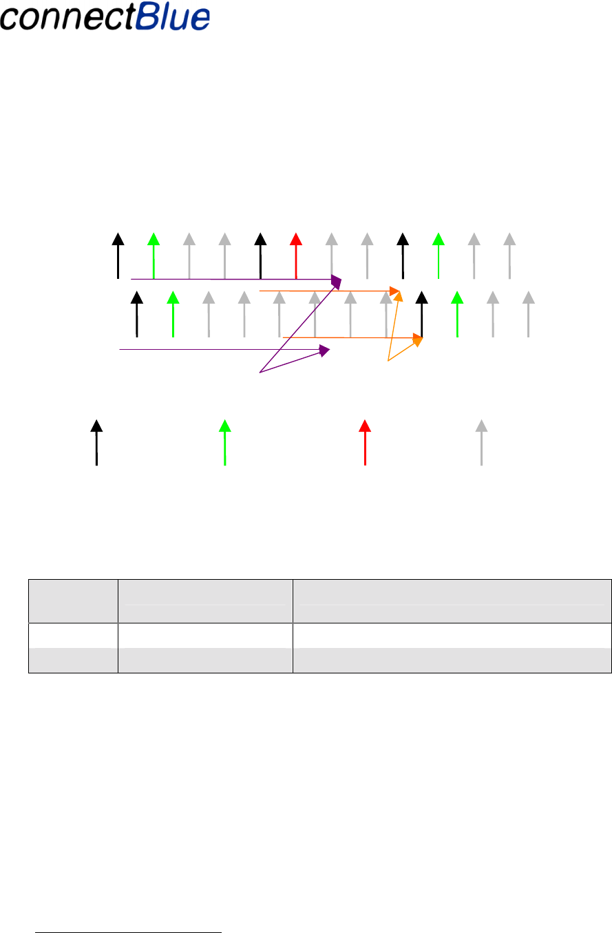
Utfärdare / Issued by Datum / Date Beteckning / Ref. Sida / Page
Andreas Hörjel, Mats Andersson 2005-06-08 cBProject-0403-01 (23) 55 (61)
Ärende / Subjekt Godkänd av / Approved by
BT IO Functional Descri
p
tion
Template update: 00-12-01
• A watchdog timer on received data packets, which alerts if data has not been received within
the timeout period. The watchdog timer is reset on reception on consistent data.
MT1
MT2
Bus Unit
HID Host
MT3
ST1
IO Unit
HID Device
Fail is detected when slave is disrupted, sniff Attempts = 2, Sniff Timeout = 0
MR1
ST3
Flush slot count = 4, Flush timeout
occurs.
SR1
N
ew data sent on
sniff slot
Data
retransmitted if
not ACK’ed
Slots with no
transmission
Poll or Null
Receive timeout fires at 6 slots.
ST2
Figure 17 - Display show a fail is detected using both the flush timeout and watchdog timer supervision
mechanisms. The IO unit has in the case fallen through and is not accessible.
A fail is detected and notified within the following times:
Fail
source Notification time2 Units
Bus unit 20 ms
IO unit 20 ms
The fail notification times indicated in the tables assumes a point-to-point connection with a sniff
interval of 5 ms. This is not applicable in a multi-point scenario. The notification times in a multi-
point scenario needs to be investigated in more detail.
4.16.2 IO-unit fail-safe management (Basic 2)
If an IO Unit running in direct IO mode detects a communication failure (as described in section
4.16.1) it will automatically set the associated IO to fail-safe values i.e.:
• Digital outputs will be set to 0
• Analog outputs are set to the 0.0.
2 Preliminary figures. Needs to be verified during the detailed design. To be verified what is possible if the unit is
used in a multi-point configuration.

Utfärdare / Issued by Datum / Date Beteckning / Ref. Sida / Page
Andreas Hörjel, Mats Andersson 2005-06-08 cBProject-0403-01 (23) 56 (61)
Ärende / Subjekt Godkänd av / Approved by
BT IO Functional Descri
p
tion
Template update: 00-12-01
If the IO unit operates in UART mode, it will notify fail-safe mode to the host using the diagnostics
interface (see section 4.10). When the communication is re-established, the IO Unit will NOT
automatically revert back to running mode. In this case is the host CPU on Bus unit is responsible for
telling the IO Unit move back from fail-safe mode to running mode (see diagnostics message
4.11.1.1.5).
The IO unit may enter fail-safe mode on command from its Bus Unit using the
management/diagnostics interface (Step 2). In this case another management/diagnostics command is
used to set the unit back to normal operation. More on the management/diagnostics messages from
the Bus Unit to the IO Unit is given in section In this case is the same management functions as
indicated above are performed (what is depending on if the unit is operating in UART or in direct IO
mode).
4.16.3 Bus Unit fail-safe management (Basic 2)
If a Bus Unit detects a communication failure (as described in section 4.16.1) it will notify the host
CPU of this using the diagnostics interface (see section 4.10). When the communication is re-
established this will be notified to the host (using the diagnostics interface, see section 4.10).
4.17 “Polling” scheme and latency
The implementation of the “copying” of IO data over the air is implemented using the Bluetooth HID
profile. The HID profile is using Bluetooth Sniff mode to implement the polling scheme. The IO Unit
and the Bus Unit is synchronized in time and every x ms interval (called sniff interval) they wakes up
and are ready to interchange data. The sniff interval will decide the latency.
An IO change is measured from the IO interface on the IO Unit to the field bus interface on the Bus
Unit, see Figure 18.
UART
BT
BT
IO
Latency is measured between these end
points
Figure 18 - Displays the end points for measuring the IO latency.
4.18 Point-to-point scenario and latency
4.18.1 Basic point-to-point (Basic 2)
The aim is an intermediate latency of 7 ms that jitters up to a maximum of 10 ms.
4.18.2 Advanced point-to-point (Step 2)
The aim is to achieve a maximum latency of 5 ms (maximum jitter is 5 ms).

Utfärdare / Issued by Datum / Date Beteckning / Ref. Sida / Page
Andreas Hörjel, Mats Andersson 2005-06-08 cBProject-0403-01 (23) 57 (61)
Ärende / Subjekt Godkänd av / Approved by
BT IO Functional Descri
p
tion
Template update: 00-12-01
4.19 Multi-point scenario and latency
The implementation of the IO is based on the Bluetooth HID profile. The Bluetooth HID profile
supports a multi-point scenario where multiple IO units might be connected to one Bus Unit (a
maximum of 7 is allowed).
The basic functionality is the same in a multi-point scenario as in the point-to-point scenario but
depending on the number of active slaves the HID sniff interval must be extended. This will influence
the latency for the individual slaves. The algorithm for setting up the sniff interval needs to be
decided in the project.
4.19.1 Basic multi-point (Basic 1)
This scenario support basic multi-point but is not optimized for latency. The following latencies are
aimed for:
No of
slaves Latency3
3 15-20 ms
7 25-35 ms
4.19.2 Advanced multi-point (Step 2)
This scenario support advanced multi-point optimized for latency. The following latencies are aimed
for:
No of
slaves Latency4
3 < 10ms
7 < 15 ms
4.20 Range (Basic 2)
Class Max
Range Hardware Type
20 dBm 100 – 200 m connectBlue BT unit with external PA and LNA
4.21 Power consumption (Basic 2)
The BT unit operates in several different modes each with specific power consumption. These values
are preliminary at current stage.
3 Preliminary figures. Needs to be verified during detailed design.
4 Preliminary figures. Needs to be verified during detailed design.

Utfärdare / Issued by Datum / Date Beteckning / Ref. Sida / Page
Andreas Hörjel, Mats Andersson 2005-06-08 cBProject-0403-01 (23) 58 (61)
Ärende / Subjekt Godkänd av / Approved by
BT IO Functional Descri
p
tion
Template update: 00-12-01
Power mode Average5 Units
Run mode communication full speed 45 mA
Run mode idle [IO unit = slave] 22 mA
Run mode idle [Bus unit = master] 5 mA
Wake up mode sniff period 100ms [IO unit] 1 mA
Power up mode disconnected [IO unit] 0 mA
5 These figures are preliminary and needs to be verified in the design phase.

Utfärdare / Issued by Datum / Date Beteckning / Ref. Sida / Page
Andreas Hörjel, Mats Andersson 2005-06-08 cBProject-0403-01 (23) 59 (61)
Ärende / Subjekt Godkänd av / Approved by
BT IO Functional Descri
p
tion
Template update: 00-12-01
5 Qualification and Test (Basic 2)
The BT Unit shall be Bluetooth qualified for the HID profile. The Bluetooth hardware is pre qualified
by CSR but some additional Bluetooth tests are required (some basic radio tests). The BT Unit is
qualified as an end product, which means that the BT unit (IO Unit and Bus Unit) can be mounted in
several products without any further Bluetooth qualification.

Utfärdare / Issued by Datum / Date Beteckning / Ref. Sida / Page
Andreas Hörjel, Mats Andersson 2005-06-08 cBProject-0403-01 (23) 60 (61)
Ärende / Subjekt Godkänd av / Approved by
BT IO Functional Descri
p
tion
Template update: 00-12-01
6 Regulatory Information
6.1 FCC Compliance
6.1.1 FCC Statement
This device complies with Part 15 of the FCC Rules. Operation is subject to the following two
conditions: (1) this device may not cause harmful interference, and (2) this device must accept any
interference received, including interference that may cause undesired operation.
NOTE: This equipment has been tested and found to comply with the limits for a Class B digital
device, pursuant to Part 15 of the FCC Rules. These limits are designed to provide reasonable
protection against harmful interference in a residential installation. This equipment generates, uses
and can radiate radio frequency energy and, if not installed and used in accordance with the
instructions, may cause harmful interference to radio communications. However, there is no
guarantee that interference will not occur in a particular installation. If this equipment does cause
harmful interference to radio or television reception, which can be determined by turning the
equipment off and on, the user is encouraged to try to correct the interference by one or more of the
following measures:
• Reorient or relocate the receiving antenna
• Increase the separation between the equipment and receiver
• Connect the equipment into an outlet on a circuit different from that to which the receiver is
connected
• Consult the dealer or an experienced radio/TV technician for help
6.1.2 RF-exposure Statement
This modular transmitter MUST have a separation distance of at least 20cm between the antenna and
the body of the user or nearby persons.
Any notification to the end user of installation or removal instructions about the integrated radio
module is NOT allowed.
6.1.3 Antenna
Our module type cB-0719-02 is for OEM integrations only. The end-user product will be installed in
such a manner that only the authorized antennas are used.
6.1.4 Caution
Any changes or modifications NOT explicitly APPROVED by connectBlue AB could cause the
module to cease to comply with FCC rules part 15, and thus void the user’s authority to operate the
equipment.

Utfärdare / Issued by Datum / Date Beteckning / Ref. Sida / Page
Andreas Hörjel, Mats Andersson 2005-06-08 cBProject-0403-01 (23) 61 (61)
Ärende / Subjekt Godkänd av / Approved by
BT IO Functional Descri
p
tion
Template update: 00-12-01
6.2 IC Compliance
Operation is subject to the following two conditions:
(1) this device may not cause harmful interference, and
(2) this device must accept any interference received,
including interference that may cause undesired operation.
This device has been designed to operate with an antenna having a maximum gain of 9 dB. Antenna
having a higher gain is strictly prohibited per regulations of Industry Canada. The required antenna
impedance is 50 ohms
To reduce potential radio interference to other users, the antenna type and its gain should be so
chosen that the equivalent isotropically radiated power (EIRP) is not more than that required for
successful communication.
6.3 Safety
The unit must be supplied by a limited power source in according to EN 60950-1.
6.4 Label and manual requirements for the End Product
For an end product using the BT Unit there must be a label containing, at least, the following
information:
This device contains
FCC ID: PVH071902
IC: 5325A-0719X
The label must be affixed on an exterior surface of the end product such that it will be visible upon
inspection in compliance with the modular approval guidelines developed by the FCC.
Where the module will be installed in final products larger than 8 cm x 10 cm following statement has
to be placed ONTO the device.
“This device complies with Part 15 of the FCC Rules.
Operation is subject to the following two conditions:
(1) this device may not cause harmful interference, and
(2) this device must accept any interference received, including interference that may cause undesired
operation.”
In case, where the final product will be installed in locations where the end-consumer is not able to
see the FCC ID and/or this statement, the FCC ID and the statement shall also be included in the end-
product manual.