u blox Malmo 072002 Wireless Communication System Module User Manual
u-blox Malmo AB Wireless Communication System Module Users Manual
UserManual.wiki
>
u blox Malmo
>
072002 User Manual
Users Manual
Navigation menu
Upload a User Manual
Namespaces
Wiki Guide
HTML
PDF
Info
Views
User Manual
Discussion / Help
Navigation
![Utfärdare / Issued by Datum / Date Beteckning / Ref. Sida / Page Mats Andersson 2005-03-30 cBProject-0503-17 (1) 4 (27) Ärende / Subjekt Godkänd av / Approved by WCS Module User Manual Template update: 00-12-01 2 Referenced documents [1] connectBlue Environmental Standard, cBProject-0202-03(1), 2002-02-04, connectBlue AB. [2] Advanced Audio Distribution Profile, Adopted version 1.0, 2003-05-25, Bluetooth SIG. [3] Specification of the Bluetooth System, Profiles, Version 1.1, 2001-02, Bluetooth SIG. [4] Hands-free Adopted Profile, Version 1.0, 2003-04-29, Bluetooth SIG](https://usermanual.wiki/u-blox-Malmo/072002/User-Guide-533703-Page-4.png)
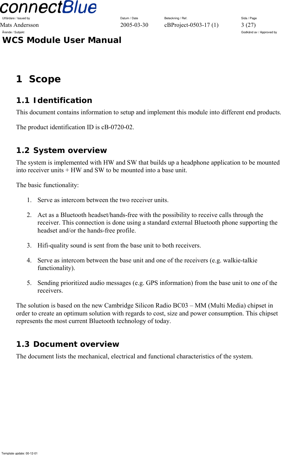
![Utfärdare / Issued by Datum / Date Beteckning / Ref. Sida / Page Mats Andersson 2005-03-30 cBProject-0503-17 (1) 6 (27) Ärende / Subjekt Godkänd av / Approved by WCS Module User Manual Template update: 00-12-01 and output to control the module. “Red” (LED-GREEN in the pinning list, section 3.4), “Green” (LED-GREEN) and “Mute” (NF-MUTE) are outputs and MF (MULTI-FUNCTION), VOL+ (VOL-DOWN), VOL- (VOL-UP) and Talk Indicator (TALK-IND) are inputs (see below for the functionality of these pins). Priorities The different sessions have the following priorities (i.e. a session with a higher priority will interrupt one with a lower priority). 1. Phone call 2. Prioritized audio messages 3. Intercom between the base-unit and one receiver. 4. Intercom between the receivers. 5. HiFi audio 3.2 Functional requirements for the Receivers 3.2.1 Bluetooth Profiles Used and Required The receiver functionality developed is using the Bluetooth Headset Profile, Headset Role and the Hands-free Profile, Hands-free role, as described in reference [3] and reference [4]. It also support the Advanced Audio Distribution Profile acting as an Audio Sink, see reference [2]. The unit may be interfaced over Bluetooth to external devices (e.g. phones) supporting the Bluetooth Headset Profile, Audio Gateway Role or the Bluetooth Hands-free Profile, Audio Gateway Role. 3.2.2 General Module Interface On the receiver there are 3 input pins, volume+ (VOL-UP), volume- (VOL-DOWN) and a multi-function input (MULTI-FUNCTION) used as the main user inputs (later called VOL+, VOL- and MF inputs). These may be used in different combinations to initiate different actions. Some actions may be initiated by keeping an input activated for a certain amount of time. There is Talk Indicator input pin (TALK-IND, later called TI), which must be generated by the host electronic on the receiver. The TI shall move from inactive to active when the receiver user starts to talk. The TI shall move back from active to inactive when the when the user stops to talk AND when no sound is heard in NF Out left and NF out right. A Mute output pin (NF-MUTE) is used to mute the sound when required. When active the sound shall be muted by the host electronics. Two LED output pins (red and green) and the ability to generate sound on the sound output are used as indicators. It uses both LED combinations and blinks respective the sound to indicate multiple modes and other indications.](https://usermanual.wiki/u-blox-Malmo/072002/User-Guide-533703-Page-6.png)
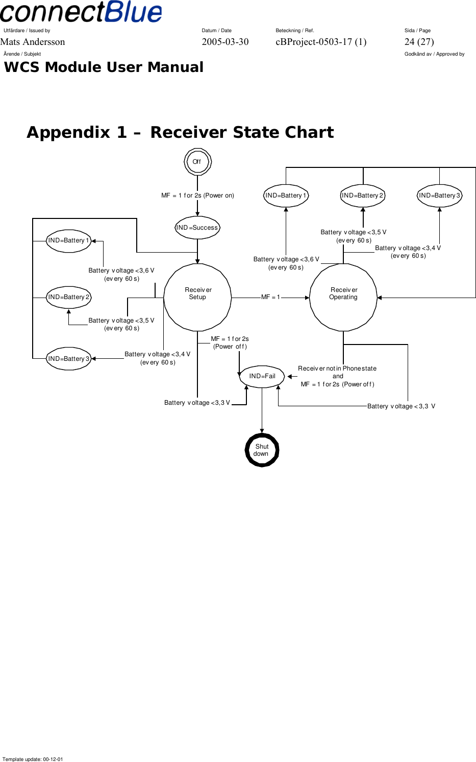
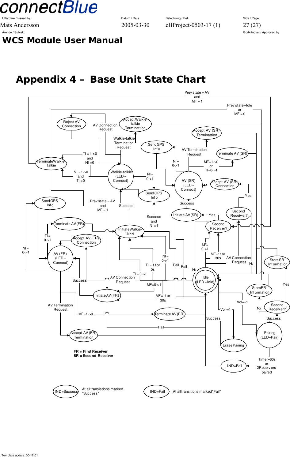
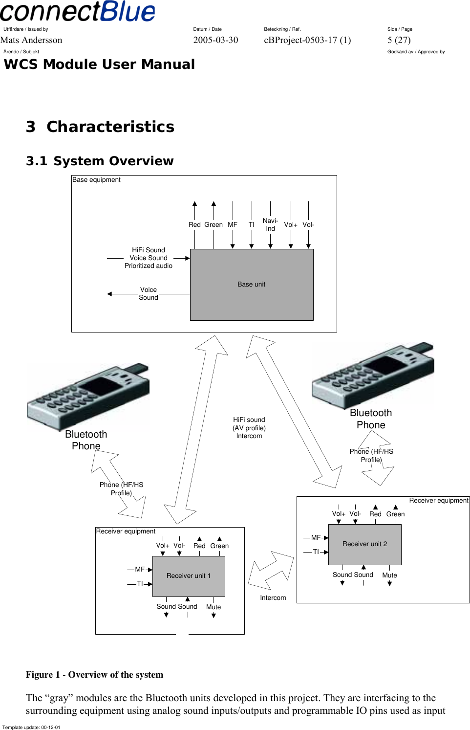
![Utfärdare / Issued by Datum / Date Beteckning / Ref. Sida / Page Mats Andersson 2005-03-30 cBProject-0503-17 (1) 12 (27) Ärende / Subjekt Godkänd av / Approved by WCS Module User Manual Template update: 00-12-01 Level 2 (below 3.5 V). Two low battery sounds are played and two red flashes on the LED PIOs are displayed periodically (every 60 s). Called IND-Battery2. Level 3 (below 3.4 V). Three low battery sounds are played and three red flashes on the LED PIOs are displayed periodically (every 60 s). Called IND-Battery3. When the battery voltage goes below 3.3 V the receiver is shut down. 3.2.11 Volume Control There is NO volume control management available on the Bluetooth Unit. All volume control is performed locally on the receiver by the receiver’s audio electronics. When the VOL+ and VOL- inputs are activated in connected mode (AV, Phone and Intercom state), no actions are taken by the Receiver Unit. 3.3 Functional requirements for the Base Unit 3.3.1 General The Base Unit is using the same Bluetooth unit as the Receivers but with a different firmware. 3.3.2 Bluetooth Profiles Used and Required The Base Unit functionality is developed using the Advanced Audio Distribution Profile, acting as an Audio Source, see reference [2]. 3.3.3 General Interface The Base Unit communicates to its host using programmable inputs and outputs. See Figure 1 for an overview of how the Bluetooth unit is interfacing other parts of the base unit electronics. It is using the same basic inputs as the Receiver (see section General Module Interface) with the following additional input: • A navigation indication input (NAVI-IND) later called NI. It is using the same basic indicators as the Receiver (see section General Module Interface) with the following additional indicators: • LED-Success. Indicated by three green flashes on the LED PIOs. • LED-Fail. Indicated by three red flashes on the LED PIOs. 3.3.4 Base Unit Operation States The Base Unit may be in three different states: 1. Idle state. This is the initial state. No communication activity. Indicated by LED-Idle. 2. AV state. A HiFi quality sound session is active. Indicated by LED-Connect.](https://usermanual.wiki/u-blox-Malmo/072002/User-Guide-533703-Page-12.png)
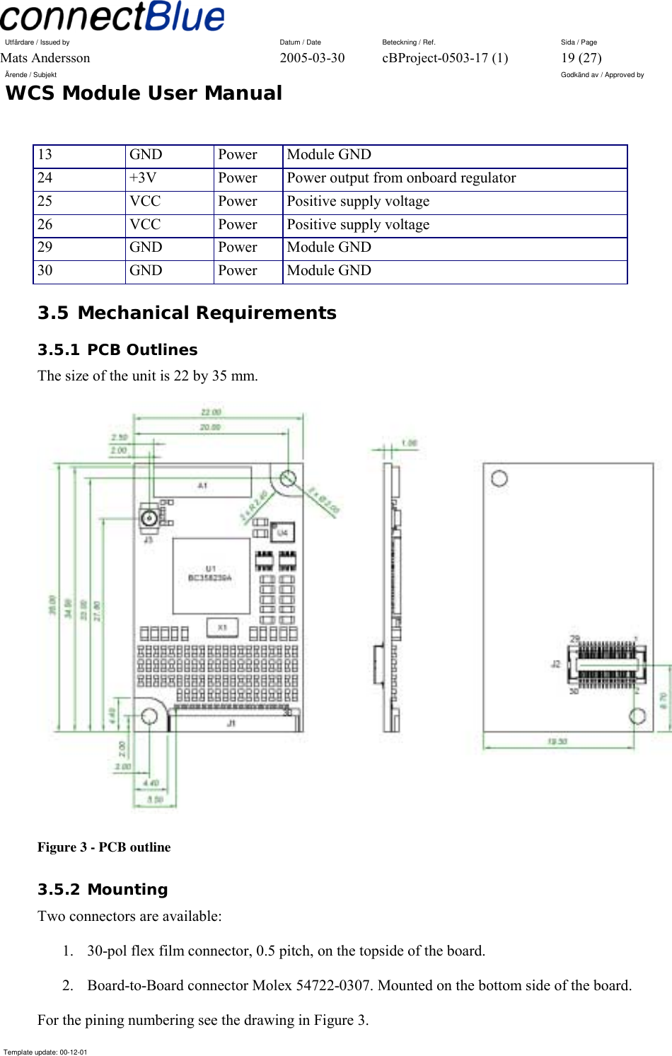
![Utfärdare / Issued by Datum / Date Beteckning / Ref. Sida / Page Mats Andersson 2005-03-30 cBProject-0503-17 (1) 20 (27) Ärende / Subjekt Godkänd av / Approved by WCS Module User Manual Template update: 00-12-01 There are two mounting holes available on the board (see Figure 3). 3.5.3 Environmental requirements The environmental requirement follows the connectBlue Environmental Standard [1]. The operating temperature range with guaranteed radio performance is from -25°C to +85°C.](https://usermanual.wiki/u-blox-Malmo/072002/User-Guide-533703-Page-20.png)