u blox Malmo 072002 Wireless Communication System Module User Manual
u-blox Malmo AB Wireless Communication System Module Users Manual
Users Manual

Utfärdare / Issued by Datum / Date Beteckning / Ref. Sida / Page
Mats Andersson 2005-03-30 cBProject-0503-17 (1) 1 (27)
Ärende / Subjekt Godkänd av / Approved by
WCS Module User Manual
Template update: 00-12-01
WCS Module User Manual
This document contains necessary information to
setup and implement this module into different
end products.

Utfärdare / Issued by Datum / Date Beteckning / Ref. Sida / Page
Mats Andersson 2005-03-30 cBProject-0503-17 (1) 2 (27)
Ärende / Subjekt Godkänd av / Approved by
WCS Module User Manual
Template update: 00-12-01
Table of content
1 Scope....................................................................................................................................... 3
1.1 Identification ................................................................................................................................ 3
1.2 System overview .......................................................................................................................... 3
1.3 Document overview ..................................................................................................................... 3
2 Referenced documents.......................................................................................................... 4
3 Characteristics....................................................................................................................... 5
3.1 System Overview ......................................................................................................................... 5
3.2 Functional requirements for the Receivers .................................................................................. 6
3.3 Functional requirements for the Base Unit ................................................................................ 12
3.4 Electrical interface requirements ...............................................................................................16
3.5 Mechanical Requirements.......................................................................................................... 19
4 Regulatory............................................................................................................................ 21
4.1 FCC Compliance........................................................................................................................ 21
4.2 IC Compliance ........................................................................................................................... 22
5 Document history................................................................................................................23
Appendix 1 – Receiver State Chart........................................................................................... 24
Appendix 2 – Receiver Operating State Chart........................................................................ 25
Appendix 3 – Receiver Setup State Chart................................................................................ 26
Appendix 4 – Base Unit State Chart......................................................................................... 27

Utfärdare / Issued by Datum / Date Beteckning / Ref. Sida / Page
Mats Andersson 2005-03-30 cBProject-0503-17 (1) 3 (27)
Ärende / Subjekt Godkänd av / Approved by
WCS Module User Manual
Template update: 00-12-01
1 Scope
1.1 Identification
This document contains information to setup and implement this module into different end products.
The product identification ID is cB-0720-02.
1.2 System overview
The system is implemented with HW and SW that builds up a headphone application to be mounted
into receiver units + HW and SW to be mounted into a base unit.
The basic functionality:
1. Serve as intercom between the two receiver units.
2. Act as a Bluetooth headset/hands-free with the possibility to receive calls through the
receiver. This connection is done using a standard external Bluetooth phone supporting the
headset and/or the hands-free profile.
3. Hifi-quality sound is sent from the base unit to both receivers.
4. Serve as intercom between the base unit and one of the receivers (e.g. walkie-talkie
functionality).
5. Sending prioritized audio messages (e.g. GPS information) from the base unit to one of the
receivers.
The solution is based on the new Cambridge Silicon Radio BC03 – MM (Multi Media) chipset in
order to create an optimum solution with regards to cost, size and power consumption. This chipset
represents the most current Bluetooth technology of today.
1.3 Document overview
The document lists the mechanical, electrical and functional characteristics of the system.

Utfärdare / Issued by Datum / Date Beteckning / Ref. Sida / Page
Mats Andersson 2005-03-30 cBProject-0503-17 (1) 4 (27)
Ärende / Subjekt Godkänd av / Approved by
WCS Module User Manual
Template update: 00-12-01
2 Referenced documents
[1] connectBlue Environmental Standard, cBProject-0202-03(1), 2002-02-04, connectBlue AB.
[2] Advanced Audio Distribution Profile, Adopted version 1.0, 2003-05-25, Bluetooth SIG.
[3] Specification of the Bluetooth System, Profiles, Version 1.1, 2001-02, Bluetooth SIG.
[4] Hands-free Adopted Profile, Version 1.0, 2003-04-29, Bluetooth SIG
Utfärdare / Issued by Datum / Date Beteckning / Ref. Sida / Page
Mats Andersson 2005-03-30 cBProject-0503-17 (1) 5 (27)
Ärende / Subjekt Godkänd av / Approved by
WCS Module User Manual
Template update: 00-12-01
3 Characteristics
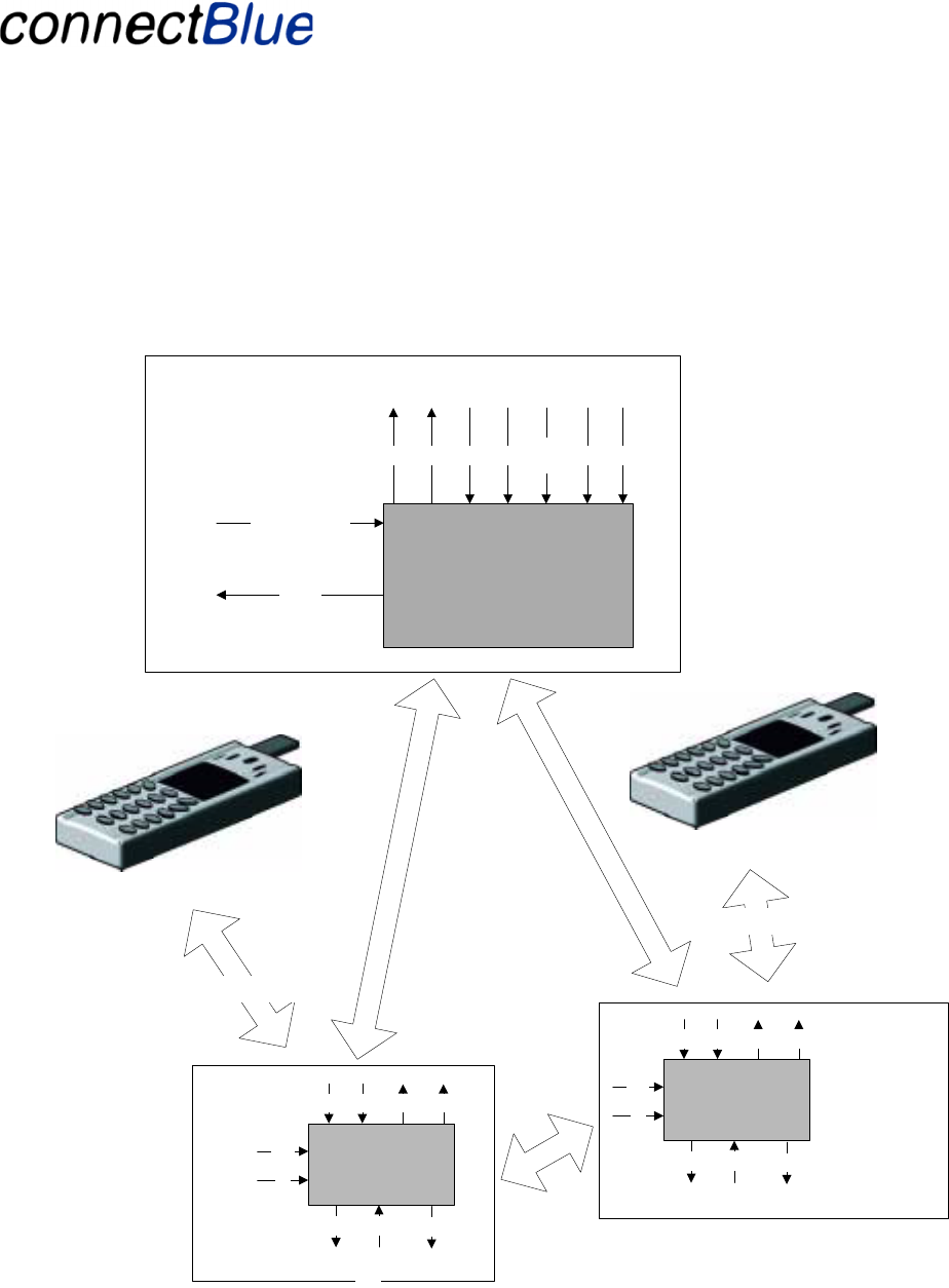
3.1 System Overview
Receiver equipment
Receiver equipment
Base equipment
Bluetooth
Phone
Bluetooth
Phone
Phone (HF/HS
Profile)
Phone (HF/HS
Profile)
Intercom
Receiver unit 1
Base unit
Red Green MF TI Navi-
Ind Vol-Vol+
HiFi Sound
Voice Sound
Prioritized audio
Voice
Sound
HiFi sound
(AV profile)
Intercom
Vol-Vol+
MF
TI
Red Green
Sound Sound Mute
Receiver unit 2
Vol-Vol+
MF
TI
Red Green
Sound Sound Mute
Figure 1 - Overview of the system
The “gray” modules are the Bluetooth units developed in this project. They are interfacing to the
surrounding equipment using analog sound inputs/outputs and programmable IO pins used as input

Utfärdare / Issued by Datum / Date Beteckning / Ref. Sida / Page
Mats Andersson 2005-03-30 cBProject-0503-17 (1) 6 (27)
Ärende / Subjekt Godkänd av / Approved by
WCS Module User Manual
Template update: 00-12-01
and output to control the module. “Red” (LED-GREEN in the pinning list, section 3.4), “Green”
(LED-GREEN) and “Mute” (NF-MUTE) are outputs and MF (MULTI-FUNCTION), VOL+ (VOL-
DOWN), VOL- (VOL-UP) and Talk Indicator (TALK-IND) are inputs (see below for the
functionality of these pins).
Priorities
The different sessions have the following priorities (i.e. a session with a higher priority will interrupt
one with a lower priority).
1. Phone call
2. Prioritized audio messages
3. Intercom between the base-unit and one receiver.
4. Intercom between the receivers.
5. HiFi audio
3.2 Functional requirements for the Receivers
3.2.1 Bluetooth Profiles Used and Required
The receiver functionality developed is using the Bluetooth Headset Profile, Headset Role and the
Hands-free Profile, Hands-free role, as described in reference [3] and reference [4]. It also support
the Advanced Audio Distribution Profile acting as an Audio Sink, see reference [2].
The unit may be interfaced over Bluetooth to external devices (e.g. phones) supporting the Bluetooth
Headset Profile, Audio Gateway Role or the Bluetooth Hands-free Profile, Audio Gateway Role.
3.2.2 General Module Interface
On the receiver there are 3 input pins, volume+ (VOL-UP), volume- (VOL-DOWN) and a multi-
function input (MULTI-FUNCTION) used as the main user inputs (later called VOL+, VOL- and MF
inputs). These may be used in different combinations to initiate different actions. Some actions may
be initiated by keeping an input activated for a certain amount of time.
There is Talk Indicator input pin (TALK-IND, later called TI), which must be generated by the host
electronic on the receiver. The TI shall move from inactive to active when the receiver user starts to
talk. The TI shall move back from active to inactive when the when the user stops to talk AND when
no sound is heard in NF Out left and NF out right.
A Mute output pin (NF-MUTE) is used to mute the sound when required. When active the sound
shall be muted by the host electronics.
Two LED output pins (red and green) and the ability to generate sound on the sound output are used
as indicators. It uses both LED combinations and blinks respective the sound to indicate multiple
modes and other indications.

Utfärdare / Issued by Datum / Date Beteckning / Ref. Sida / Page
Mats Andersson 2005-03-30 cBProject-0503-17 (1) 7 (27)
Ärende / Subjekt Godkänd av / Approved by
WCS Module User Manual
Template update: 00-12-01
See Figure 1 for an overview of how the Bluetooth module is interfacing the rest of the Receiver
electronics.
The user interface consists of three main modes.
• Setup (indicated with very fast green blinks on the LED PIO). Later called LED-Setup.
• Idle (indicated with slow green blinks on the LED PIO). Later called LED-Idle.
• Pairing (indicated with fast green blinks on the LED PIO). Later called LED-Pair.
• Connected (indicated with permanent green light on the LED PIO). Later called LED-
Connect.
The LED PIOs and sounds are also used to indicate if a user action was successful or not. Two
different indications are used:
• Successful operation. A “light” sound (OK sound) and a very long blink with the green LED
PIO. Later called IND-Success.
• Unsuccessful operation. A “dark” sound (Fail sound) and red LED PIO flashes three times.
Later called IND-Fail.
To indicate an incoming call from a phone an internally generated ring sound is used (later called
IND-Ring).
The idea behind the user interface is that all normal actions are made with the MF input or no inputs
at all. More specialized functions are made with the volume inputs.
3.2.3 Power on and shut down the receiver
The receiver is powered up by activating the MF input more than 2 seconds. Now the receiver starts
in setup mode and issues an IND-Success indication. When the module is started the Mute pin is
activate and then it will be set inactive during normal operation. The Power On pin is set to active to
control the power supply.
Activating the MF input more than 2 seconds shut down the receiver (in all modes except when there
is an ongoing phone call). When the receiver is ready to power down, the IND-Fail indication is
issued. To get rid of click sounds, the Mute pin is activated. After the MF input is deactivated the
system waits for 1 second and finally the PowerOn pin is deactivated to shut down the board.
3.2.4 Setting up the receiver
After the receiver is powered up the receiver is in setup mode, now pairing of the receiver can be
performed.
To leave the setup mode activate the MF input shortly. The receiver goes into idle mode.
3.2.4.1 Pairing the receiver

Utfärdare / Issued by Datum / Date Beteckning / Ref. Sida / Page
Mats Andersson 2005-03-30 cBProject-0503-17 (1) 8 (27)
Ärende / Subjekt Godkänd av / Approved by
WCS Module User Manual
Template update: 00-12-01
Pairing is performed in setup mode only.
3.2.4.1.1 Pairing with a phone
Activate the VOL+ input shortly (less than 2 seconds). The receiver goes into pairable mode
(indicated by LED-Pair) and the receiver will be discoverable for other units. Initiate the pairing from
the phone (the method for doing this is dependant on the phone used). Use the hard-coded PIN code
value for the receiver (“0000”).
The receiver will stay pairable for 60 seconds.
At a successful pairing a “successful operation” is indicated by IND-Success. If the pairing fails an
“unsuccessful operation” is indicated (IND-Failure).
After a pairing (successful or unsuccessful), the receiver returns to the setup state.
3.2.4.1.2 Pairing with another Receiver
Activate the VOL+ input on the first receiver shortly (<2 seconds). The receiver goes into pairable
mode (indicated by LED-Pair) and the receiver will be discoverable for other units.
Activate the VOL+ input long (>2 seconds) on the second receiver. The receiver will enter pairing
mode and will start to search for the other receiver (indicated by LED-Pair).
At a successful pairing a “successful operation” is indicated (IND-Success). If the pairing fails an
“unsuccessful operation” is indicated (IND-Fail).
After a pairing (successful or unsuccessful), the receiver returns to the setup state.
3.2.4.1.3 Pairing with the Base Unit.
Activate the VOL+ input shortly (less than 2 seconds). The receiver goes into pairable mode
(indicated by LED-Pair) and the receiver will be discoverable for other units. Initiate the pairing from
the Base Unit (see section 3.3).
3.2.4.1.4 Remove pairing information
Activating VOL- long (>2s) will remove all pairing information from the receiver. A “successful
operation” is indicated (IND-Success). This is only allowed in the SETUP state.
3.2.5 Receiver Operation States
The receiver may be in six different states:
1. Setup state. This is the initial state. Pairing of the receiver can be performed. Indicated on the
LED PIOs by LED-Setup.
2. Idle state. No communication links are active. Indicated on the LED PIOs by LED-Idle.

Utfärdare / Issued by Datum / Date Beteckning / Ref. Sida / Page
Mats Andersson 2005-03-30 cBProject-0503-17 (1) 9 (27)
Ärende / Subjekt Godkänd av / Approved by
WCS Module User Manual
Template update: 00-12-01
3. Intercom state. Intercom between the two receivers is active. Indicated on the LED PIOs by
LED-Connect.
4. Phone state. An active phone call is connected. Indicated on the LED PIOs by LED-Connect.
5. AV state. An active Hifi quality sound session is active. Indicated on the LED PIOs by LED-
Connect.
6. Walkie-talkie state. An active intercom session between the base unit and the receiver is
active. Indicated on the LED PIOs by LED-Connect. (This state can only exist in one of the
receivers, the one first paired with the base unit)
Observe that a prioritized audio message session will use an active HiFi or walkie-talkie session for
transmitting the information to the receiver. If there is no active session, a walkie-talkie session will
be created, i.e. there is no specific prioritized audio message session in the receiver.
3.2.6 Intercom State Functionality
Intercom state may be entered from either AV state or Idle state. The Talk Indicator (TI) is used to
initiate and leave the Intercom state.
3.2.6.1 Entering intercom state initiated from the receiver
1. The TI activity is not monitored if no other receiver is paired with the current receiver.
2. The receiver monitors the TI (if in Idle or AV mode only). If TI moves from inactive to active
the receiver will try to establish an intercom session to the other receiver.
3. If there is an on-going AV session this session will immediately be closed down before the
intercom session is established.
4. If the establishment fails the IND-Fail indication is issued and the control is moved back to
the previous state. If the previous state was the AV state the AV session will be re-established
(the AV sound is faded in). If the previous state was Idle and the TI is active a retry is
performed once every 8-20 seconds (randomly).
3.2.6.2 Entering intercom state initiated from the other receiver
1. If we are in the Phone state the incoming request is rejected.
2. If we are in the AV state the AV session will be closed down.
3. The incoming request is accepted, the receiver is set to the Intercom state.
3.2.6.3 Closing down an intercom session
1. The TI is monitored continuously.
2. If the previous state (the state before entering Intercom) was the Idle state and the TI been
inactive for more than 120 sec (or 10 sec if a request to initiate an AV session was received

Utfärdare / Issued by Datum / Date Beteckning / Ref. Sida / Page
Mats Andersson 2005-03-30 cBProject-0503-17 (1) 10 (27)
Ärende / Subjekt Godkänd av / Approved by
WCS Module User Manual
Template update: 00-12-01
during the Intercom session) the Intercom session is terminated and the receiver is moved to
Idle state.
3. If the previous state was the AV State and the TI been inactive for more than 10 sec the
Intercom session is terminated.
An AV connection is initiated and faded in. If successful, the unit is moved to the AV State.
If unsuccessful an IND-Fail is issued and the unit is moved to the Idle state.
For the operation on an incoming phone call or a request to initiate an intercom session with the base
unit see sections 3.2.7 and 3.2.9.
3.2.7 Phone State Functionality
3.2.7.1 Receiving an incoming phone call on a receiver
1. The phone connects to the receiver and issues a request to accept a call.
2. An ongoing intercom session or AV session is interrupted.
3. An internal generated ring signal (IND-Ring) is played in the receiver.
4. Activate the MF input shortly to reject the call.
5. The call will automatically be accepted after 5 seconds. The unit is moved to the Phone state.
3.2.7.2 Stopping a phone call
1. The call is stopped either by activating the MF input for more than 2s or when the calling
phone is canceling the call.
2. If previous state (the state before the Phone issued the call) was the AV state, an AV session
will be re-established, the sound is faded in and the unit is moved to the AV state. If
unsuccessful an IND-Fail is issued and the unit is moved to the Idle state.
3. If an intercom session was active when the phone call was initiated the intercom session will
automatically be re-established if the talk indicator (TI) is active. Otherwise the unit is moved
to the Idle state.
4. If an intercom session with the base unit was active when the phone call was initiated the unit
will be moved to the Idle state.
5. If the previous state was the Idle state the unit is moved to the Idle state.
3.2.7.3 Transferring a phone call to and from the phone
1. An ongoing phone call is transferred to the phone by a short activation of the MF input. The
unit is moved to the previous state except for an intercom session with the base unit when it is
moved to the Idle state instead.

Utfärdare / Issued by Datum / Date Beteckning / Ref. Sida / Page
Mats Andersson 2005-03-30 cBProject-0503-17 (1) 11 (27)
Ärende / Subjekt Godkänd av / Approved by
WCS Module User Manual
Template update: 00-12-01
2. If the unit is in the Idle state a phone call is transferred back from the phone to the receiver by
an activation of the MF input.
3.2.8 AV State Functionality
The AV state is always initially initiated from the base unit (or other AV device). Initial procedure:
1. The Receiver receives a request to initiate an AV session.
2. If the Receiver is in any other state than the Idle state the request will be rejected.
3. If the Receiver is in the Idle state the request will be accepted and the Receiver is moved to
the AV state. If unsuccessful an IND-Fail is issued and the unit stays in the Idle state.
For the operation on an incoming phone call, a request to initiate an intercom session with the base
unit or a request to initiate an Intercom session see sections 3.2.6, 3.2.9 and 3.2.7.
3.2.9 Walkie-talkie (Intercom with the Base Unit) State Functionality
Walkie-talkie state may be entered from either Intercom state, AV state or Idle state. The walkie-
talkie state is always initiated from the base unit and can only exist in the first receiver to be paired
with the base unit.
3.2.9.1 Entering Walkie-talkie State
This is always initiated from the base unit.
1. If we are in the Phone state the incoming request is rejected.
2. If we are in the AV state or Intercom state the ongoing session will be interrupted.
3. The incoming request is accepted, the receiver is set to the Walkie-talkie state.
3.2.9.2 Closing down a walkie-talkie session
This is always initiated from the base unit.
1. The termination request is accepted.
2. The receiver is moved to Idle state.
For the operation on an incoming phone call see section 3.2.7.
3.2.10 Low battery indication
The battery voltage is monitored and three warning levels are used.
Level 1 (below 3.6 V). One low battery sound is played and single red flash on the LED PIOs is
displayed periodically (every 60 s). Called IND-Battery1.

Utfärdare / Issued by Datum / Date Beteckning / Ref. Sida / Page
Mats Andersson 2005-03-30 cBProject-0503-17 (1) 12 (27)
Ärende / Subjekt Godkänd av / Approved by
WCS Module User Manual
Template update: 00-12-01
Level 2 (below 3.5 V). Two low battery sounds are played and two red flashes on the LED PIOs are
displayed periodically (every 60 s). Called IND-Battery2.
Level 3 (below 3.4 V). Three low battery sounds are played and three red flashes on the LED PIOs
are displayed periodically (every 60 s). Called IND-Battery3.
When the battery voltage goes below 3.3 V the receiver is shut down.
3.2.11 Volume Control
There is NO volume control management available on the Bluetooth Unit. All volume control is
performed locally on the receiver by the receiver’s audio electronics. When the VOL+ and VOL-
inputs are activated in connected mode (AV, Phone and Intercom state), no actions are taken by the
Receiver Unit.
3.3 Functional requirements for the Base Unit
3.3.1 General
The Base Unit is using the same Bluetooth unit as the Receivers but with a different firmware.
3.3.2 Bluetooth Profiles Used and Required
The Base Unit functionality is developed using the Advanced Audio Distribution Profile, acting as an
Audio Source, see reference [2].
3.3.3 General Interface
The Base Unit communicates to its host using programmable inputs and outputs. See Figure 1 for an
overview of how the Bluetooth unit is interfacing other parts of the base unit electronics.
It is using the same basic inputs as the Receiver (see section General Module Interface) with the
following additional input:
• A navigation indication input (NAVI-IND) later called NI.
It is using the same basic indicators as the Receiver (see section General Module Interface) with the
following additional indicators:
• LED-Success. Indicated by three green flashes on the LED PIOs.
• LED-Fail. Indicated by three red flashes on the LED PIOs.
3.3.4 Base Unit Operation States
The Base Unit may be in three different states:
1. Idle state. This is the initial state. No communication activity. Indicated by LED-Idle.
2. AV state. A HiFi quality sound session is active. Indicated by LED-Connect.

Utfärdare / Issued by Datum / Date Beteckning / Ref. Sida / Page
Mats Andersson 2005-03-30 cBProject-0503-17 (1) 13 (27)
Ärende / Subjekt Godkänd av / Approved by
WCS Module User Manual
Template update: 00-12-01
3. Walkie-talkie state. An intercom session with a receiver is active. Indicated by LED-Connect.
Prioritized audio messages (e.g. navigation information from GPS) does not use a separate state.
Instead the information is sent via walkie-talkie or AV.
3.3.5 AV State
AV state may be entered from the Idle state. MF is used to initiate and leave the Intercom state. This
state is indicated by LED-Connect.
3.3.5.1 Establish an AV session
1. If MF moves from inactive to active the base unit will try to establish an AV session.
2. If the establishment succeeds the IND-Success indication is issued and the Base Unit is
moved to the AV state.
3. If the establishment fails the IND-Fail indication is issued and the control is moved back to
the Idle state. If MF is still active a retry is performed once every 30 seconds.
4. A receiver may request to set-up the AV connection. When the connection request is accepted
the Base Unit is moved to the AV state
3.3.5.2 Establish an AV session initiated from a receiver
This is performed when a receiver wants to re-connect after it has interrupted an AV session due to an
incoming phone call or an intercom session.
1. The base unit receives a request to initiate an AV session.
2. If the base unit is in any other state than the Idle state the request will be rejected.
3. If the Receiver is in the Idle state the request will be accepted and the base unit is moved to
the AV state.
3.3.5.3 Stopping an AV session
If the MF drops from active to inactive the AV connections will be terminated and the unit moves to
the Idle state.
If a receiver requests to terminate the AV connection (e.g. the receiver is moved out of range, receives
a phone call or is powered off) the base unit is moved to the Idle state.
3.3.6 Idle State
The Base Unit is moved to Idle state if both the MF and TI drops from active to inactive state. All
open connections to the receivers are closed down.
As long as TI is high a retry to set up a walkie-talkie session is performed every 5 seconds.
As long as MF is high a retry to set up the AV connection is performed every 30 seconds.

Utfärdare / Issued by Datum / Date Beteckning / Ref. Sida / Page
Mats Andersson 2005-03-30 cBProject-0503-17 (1) 14 (27)
Ärende / Subjekt Godkänd av / Approved by
WCS Module User Manual
Template update: 00-12-01
If VOL- goes high all pairing information is erased. IND-Success indication is issued when finished.
The Idle stat is indicated by LED-Idle.
3.3.7 Pairing State
Pairing state may be entered from the Idle state only.
1. Pairing state is entered when VOL+ is moved inactive to active state.
2. If two receivers already are paired no searching will be performed and an LED-Fail indication
will be issued. To perform a successful pairing the pairing information has to be erased (see
3.3.6).
3. In pairing state the Base Unit is searching for a Receiver in pairable state. If a receiver is
found the predefined key (0000) is used to pair with the receiver and LED-Success is
indicated.
4. If it was the first receiver paired it will be stored as the first receiver. If it was the second it
will be stored as the second receiver. If no second receiver is used and a the first receiver has
to be re-paired the pairing information has to be erased (see 3.3.6).
5. The searching is active for 60 seconds and if the searching fails the LED-Fail indication is
issued.
6. In all cases the Base Unit is moved back to idle state when finished.
3.3.8 Walkie-talkie State
Walkie-talkie state may be entered from either AV state or Idle state. The walkie-talkie state is never
initiated from a receiver and will only connect to the first receiver paired with the base unit.
3.3.8.1 Entering Walkie-talkie State
This is always initiated from the base unit.
1. If TI moves from inactive to active the base unit will try to establish an intercom session with
the first receiver paired with the base unit.
2. If there is an on-going AV session this session will immediately be closed down before the
intercom session with the first receiver paired with the base unit is established.
3. If the establishment succeeds the LED-Success indication is issued and the Base Unit is
moved to the walkie-talkie state.
4. If the establishment fails the LED-Fail indication is issued and the control is moved back to
the Idle state. If TI is still active a retry is performed once every 5 seconds.
3.3.8.2 Closing down an intercom session with the first receiver paired with the base unit

Utfärdare / Issued by Datum / Date Beteckning / Ref. Sida / Page
Mats Andersson 2005-03-30 cBProject-0503-17 (1) 15 (27)
Ärende / Subjekt Godkänd av / Approved by
WCS Module User Manual
Template update: 00-12-01
1. The TI and NI are monitored continuously.
2. When both the TI and NI become inactive the intercom session with the first receiver paired
with the base unit is terminated.
3. If the previous state was the Idle state or the MF is inactive the base unit is moved to Idle
state.
4. If the previous state was the AV State and the MF is active an AV connection is initiated. If
successful, the unit is moved to the AV State. If unsuccessful an LED-Fail is issued and the
unit is moved to the Idle state.
The intercom session with the first receiver paired with the base unit can be terminated from the
receiver if it receives a phone call. Then the termination request is accepted and the base unit is
moved to the Idle state. If the TI is still active a retry to establish an intercom session with the first
receiver paired with the base unit is performed every 5 seconds.
3.3.9 Prioritized Audio Messages functionality
The prioritized audio messages (e.g. navigation information from GPS) functionality does not have an
own state. It uses the active session to transmit the info to the receiver(s). The NI becomes active
before the navigation info is sent and goes inactive when the info is finished.
1. If an AV session is active the navigation info is sent to the receivers using that.
2. If an intercom session with the first receiver paired with the base unit session is active the
navigation info is sent using that.
In both cases the Bluetooth unit does not actively use the NI.
If the base unit is in the Idle state and the NI becomes active an intercom session with the first
receiver paired with the base unit is established and the navigation info is sent using that. The
intercom session with the first receiver paired with the base unit is terminated according to 3.3.8.2.
Utfärdare / Issued by Datum / Date Beteckning / Ref. Sida / Page
Mats Andersson 2005-03-30 cBProject-0503-17 (1) 16 (27)
Ärende / Subjekt Godkänd av / Approved by
WCS Module User Manual
Template update: 00-12-01
3.4 Electrical interface requirements
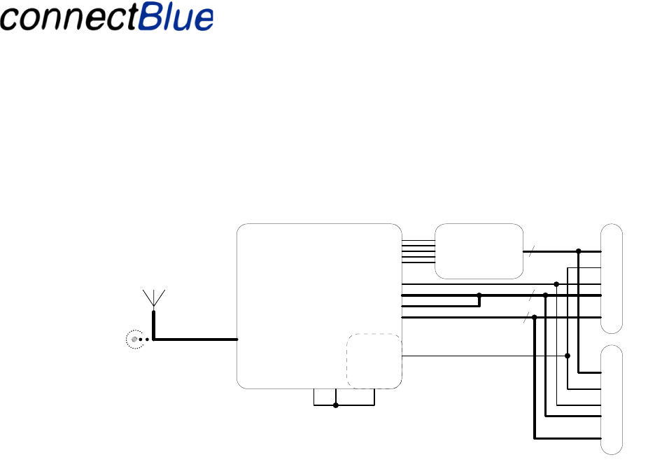
3.4.1 Overview
CSR BC358239A
Radio & Baseband
Bluetooth IC
Power supply
+1V8
Vin
(2.2V - 4.2V)
RF-connect
Analog
-I/O
Digital-I/O
UART
SPI
RESET-n
Analog
Interface
4
9
5
Optional External
Antenna connector
J3
Internal Antenna
J1
J2
Module Interface
Figure 2 - HW Block Diagram
The Bluetooth unit is based on the Cambridge Silicon Radio Bluecore3 Multimedia chip
(BC358239A). This chip includes a processor (for the Bluetooth stack and application), a DSP (for
handling of the audio encoding/decoding) and the necessary analog to digital and digital to analog
converters.
The unit will use 3 inputs and 2 LED ouputss (red + green light) as a user interface with the
functionality described previously. These will be connected in a connector (J1 and j2) and not
mounted on the board. The buttons are directly connected to the CPU.
The audio in will come into the system from connected to the connector. There is a possibility for
separate left and right channel sound input.
The audio out will be feed from the system separated into a left and a right channel.
The unit will also have a connector to an 8 bits A/D converter included in the base band circuit that is
used to check the battery voltage.
There are 2 connectors available on the unit:
• 30 poles flex film connector with base functionality (J1). The flex film connector pin usage is
designed to be compatible with the generation 1 module wherever possible. Se tables below
for exceptions from this.
• 30 poles Board-to-Board connector mounted on the bottom side of the unit (J2).
3.4.2 Audio Signal Interface
The Audio output signals can has the following behavior:
Utfärdare / Issued by Datum / Date Beteckning / Ref. Sida / Page
Mats Andersson 2005-03-30 cBProject-0503-17 (1) 17 (27)
Ärende / Subjekt Godkänd av / Approved by
WCS Module User Manual
Template update: 00-12-01
1. AC or DC coupled differential output capable of driving 2Vpp into 600 Ω, maximum load
impedance is 22 Ω.
DC bias level is 0.8 V
The Audio-input signals has the following behavior:
1. Differential line input, input impedance 130 kΩ.
Use the left channel for mono input signal is needed only (e.g. inside the receivers).
Connector
pin nr. Pin Name Type Description
1 NF-OUT-
INVL
Audio
Output
Left audio output.
2 NF-OUT-L Audio
Output
Left audio output.
3 NF-OUT-
INVR
Audio
Output
Right audio output.
4 NF-OUT-R Audio
Output
Right audio output.
5 MIC-INPUT-
INVL
Audio
Input
Left audio input. Used when mono only is required.
6 MIC-INPUT-
L
Audio
Input
Left audio input. Used when mono only is required.
27 MIC-INPUT-
INVR
Audio
Input
Right audio input. Required for stereo input. Replaces
a VCC pin on generation 1.
28 MIC-INPUT-
R
Audio
Input
Right audio input. Required for stereo input. Replaces
a GND pin on generation 1.
3.4.3 Analog IO
The analog input signal level is between 0 – 5.5 V. This input is used for battery supervision.
Connector
pin nr. Pin Name Type Description
8 AN-IN Analog
Input
Connected to Bluecore3-MM via a resistive voltage
divider.
3.4.4 Logic level SPI-communication
This interface is used for debugging and FW download purposes.
Connector
pin nr. Pin Name Type Description
Utfärdare / Issued by Datum / Date Beteckning / Ref. Sida / Page
Mats Andersson 2005-03-30 cBProject-0503-17 (1) 18 (27)
Ärende / Subjekt Godkänd av / Approved by
WCS Module User Manual
Template update: 00-12-01
9 SPI-MISO SPI
10 SPI-CLK SPI
11 SPI-MOSI SPI
12 SPI-CSB SPI
14 RESET-N Digital
IO
Reset. Active low.
3.4.5 Digital IO
The module digital interface voltage input levels are logic level CMOS i.e. VIL < 0.3 x VCC VIH >
0.7 x VCC.
All digital I/O-signals have weak pull down and will function as inputs after reset until reconfigured
by software.
Connector
pin nr. Pin Name Type Description
15 NAVI-IND Digital
IO
Input. Active high.
16 TALK-IND Digital
IO
Input. Active high. See section 3.2 for the
functionality of the pin.
17 POWER-
ON
Digital
IO
Output. Active high. Controls the power supply unit.
18 NF-MUTE Digital
IO
Output. Active low. Used to mute the audio
amplifier when needed.
19 LED-
GREEN
Digital
IO
Output. Active high. See section 3.2 for the
functionality of the pin.
20 LED-RED Digital
IO
Output. Active high. See section 3.2 for the
functionality of the pin.
21 MULTI-
FUNCTION
Digital
IO
Input. Active high. See section 3.2 for the
functionality of the pin.
22 VOL-
DOWN
Digital
IO
Input. Active high. See section 3.2 for the
functionality of the pin.
23 UP Digital
IO
Input. Active high. See section 3.2 for the
functionality of the pin.
3.4.6 Power Connections
The module supply voltage can be between 3 – 3.3 V. The +3V signal on pin 24 will be connected to
VCC internally on the module.
Connector
pin nr. Pin Name Type Description
7 GND Power Module GND
Utfärdare / Issued by Datum / Date Beteckning / Ref. Sida / Page
Mats Andersson 2005-03-30 cBProject-0503-17 (1) 19 (27)
Ärende / Subjekt Godkänd av / Approved by
WCS Module User Manual
Template update: 00-12-01
13 GND Power Module GND
24 +3V Power Power output from onboard regulator
25 VCC Power Positive supply voltage
26 VCC Power Positive supply voltage
29 GND Power Module GND
30 GND Power Module GND
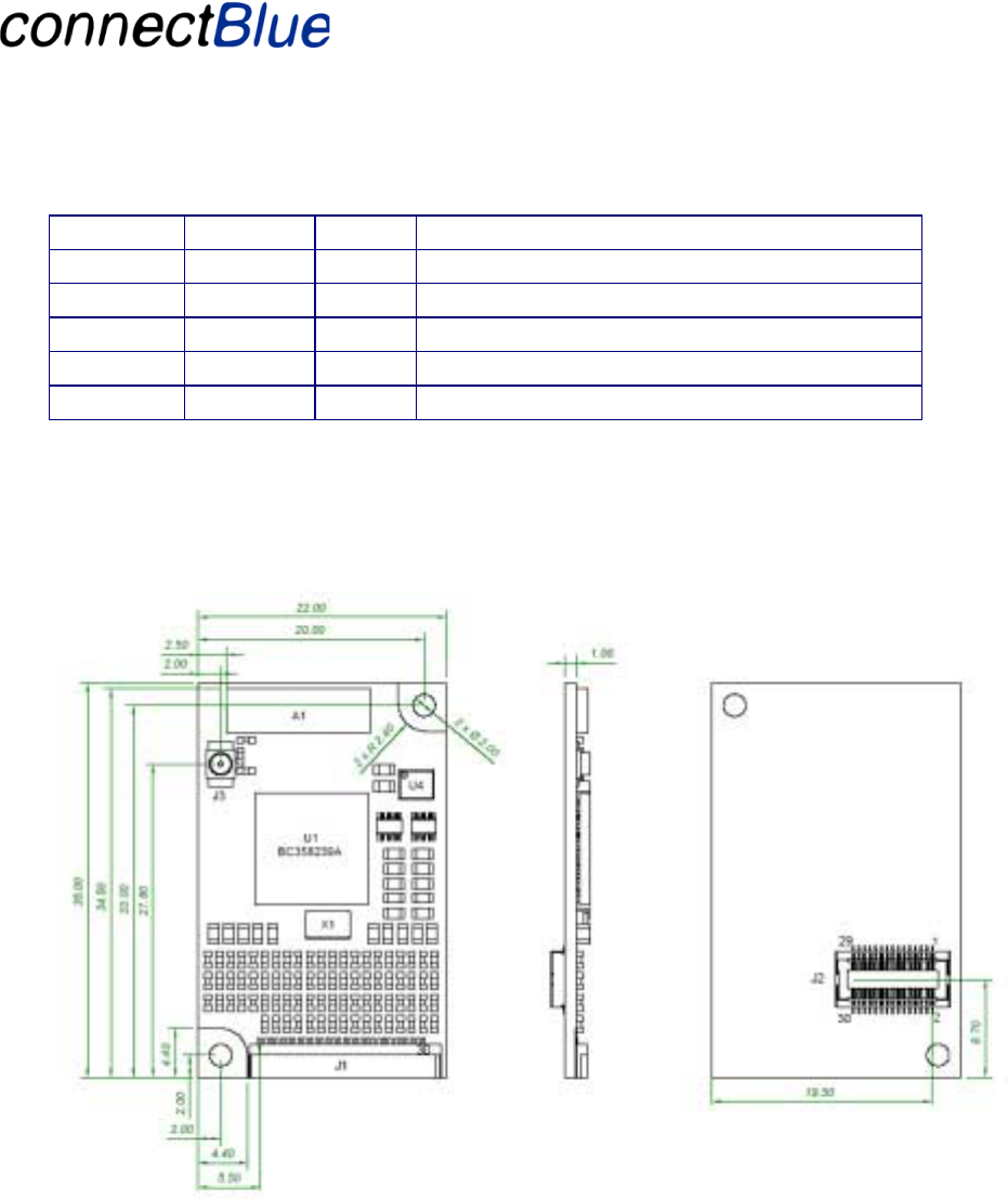
3.5 Mechanical Requirements
3.5.1 PCB Outlines
The size of the unit is 22 by 35 mm.
Figure 3 - PCB outline
3.5.2 Mounting
Two connectors are available:
1. 30-pol flex film connector, 0.5 pitch, on the topside of the board.
2. Board-to-Board connector Molex 54722-0307. Mounted on the bottom side of the board.
For the pining numbering see the drawing in Figure 3.

Utfärdare / Issued by Datum / Date Beteckning / Ref. Sida / Page
Mats Andersson 2005-03-30 cBProject-0503-17 (1) 20 (27)
Ärende / Subjekt Godkänd av / Approved by
WCS Module User Manual
Template update: 00-12-01
There are two mounting holes available on the board (see Figure 3).
3.5.3 Environmental requirements
The environmental requirement follows the connectBlue Environmental Standard [1].
The operating temperature range with guaranteed radio performance is from -25°C to +85°C.

Utfärdare / Issued by Datum / Date Beteckning / Ref. Sida / Page
Mats Andersson 2005-03-30 cBProject-0503-17 (1) 21 (27)
Ärende / Subjekt Godkänd av / Approved by
WCS Module User Manual
Template update: 00-12-01
4 Regulatory
4.1 FCC Compliance
4.1.1 FCC Statement
This device complies with RF-exposure evaluation for portable devices in FCC rules section 2.1093.
This device complies with Part 15 of the FCC Rules. Operation is subject to the following two
conditions: (1) this device may not cause harmful interference, and (2) this device must accept any
interference received, including interference that may cause undesired operation.
NOTE: This equipment has been tested and found to comply with the limits for a Class B digital
device, pursuant to Part 15 of the FCC Rules. These limits are designed to provide reasonable
protection against harmful interference in a residential installation. This equipment generates, uses
and can radiate radio frequency energy and, if not installed and used in accordance with the
instructions, may cause harmful interference to radio communications. However, there is no
guarantee that interference will not occur in a particular installation. If this equipment does cause
harmful interference to radio or television reception, which can be determined by turning the
equipment off and on, the user is encouraged to try to correct the interference by one or more of the
following measures:
• Reorient or relocate the receiving antenna
• Increase the separation between the equipment and receiver
• Connect the equipment into an outlet on a circuit different from that to which the receiver is
connected
• Consult the dealer or an experienced radio/TV technician for help
4.1.2 Labeling Requirements for End Product
For an end product using the OEM Serial Port Adapter or the OEM Bluetooth Enabler there must be a
label containing, at least, the following information:
The label must be affixed on an exterior surface of the end product such that it will be visible upon
inspection in compliance with the modular approval guidelines developed by the FCC.
Where the module will be installed in final products larger than 8 cm x 10 cm following statement has
to be placed ONTO the device.
“This device complies with Part 15 of the FCC Rules.
Operation is subject to the following two conditions:
This device contains
FCC ID PVH072002

Utfärdare / Issued by Datum / Date Beteckning / Ref. Sida / Page
Mats Andersson 2005-03-30 cBProject-0503-17 (1) 22 (27)
Ärende / Subjekt Godkänd av / Approved by
WCS Module User Manual
Template update: 00-12-01
(1) this device may not cause harmful interference, and
(2) this device must accept any interference received, including interference that may cause undesired
operation.”
In case, where the final product will be installed in locations where the end-consumer is not able to
see the FCC ID and/or this statement, the FCC ID and the statement shall also be included in the end-
product manual.
4.1.3 Caution
Changes or modifications not expressly approved by the party responsible for compliance
could void the user's authority to operate the equipment.
4.2 IC Compliance
“Operation is subject to the following two conditions:
(1) this device may not cause harmful interference, and
(2) this device must accept any interference received,
including interference that may cause undesired operation.”
4.3 Safety
Must be supplied by a limited power source in according to EN 60950-1. In this case no fire enclosure
is necessary. But the installer is responsible for the correct electrical installation!

Utfärdare / Issued by Datum / Date Beteckning / Ref. Sida / Page
Mats Andersson 2005-03-30 cBProject-0503-17 (1) 23 (27)
Ärende / Subjekt Godkänd av / Approved by
WCS Module User Manual
Template update: 00-12-01
5 Document history
Version Date Comment
1 2005-03-29 Initial version
Utfärdare / Issued by Datum / Date Beteckning / Ref. Sida / Page
Mats Andersson 2005-03-30 cBProject-0503-17 (1) 24 (27)
Ärende / Subjekt Godkänd av / Approved by
WCS Module User Manual
Template update: 00-12-01
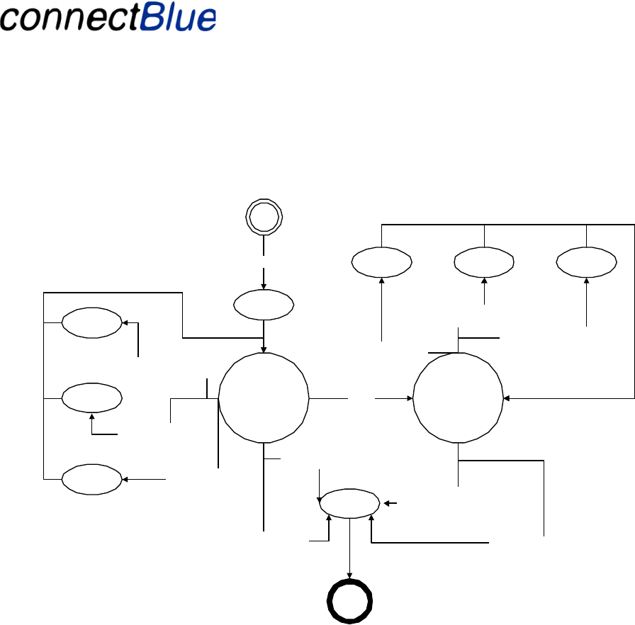
Appendix 1 – Receiver State Chart
Receiver
Operating
MF = 1
IND = Success
Shut
down
MF = 1 f or 2s
(Power off)
Receiv er not in Phone state
and
MF = 1 for 2s (Power of f)
IND = Fail
IND = Battery1 IND = Battery 2 IND = Battery3
IND = Battery 1
IND = Battery 2
IND = Battery 3 Battery v oltage < 3,4 V
(every 60 s)
Battery voltage < 3,5 V
(every 60 s)
Battery voltage < 3,6 V
(every 60 s)
Battery voltage < 3,6 V
(ev ery 60 s)
Battery voltage < 3,5 V
(every 60 s) Battery v oltage < 3,4 V
(ev ery 60 s)
Receiver
Setup
MF = 1 for 2s (Power on)
Of f
Battery v oltage < 3,3 V
Battery voltage < 3,3 V
Utfärdare / Issued by Datum / Date Beteckning / Ref. Sida / Page
Mats Andersson 2005-03-30 cBProject-0503-17 (1) 25 (27)
Ärende / Subjekt Godkänd av / Approved by
WCS Module User Manual
Template update: 00-12-01
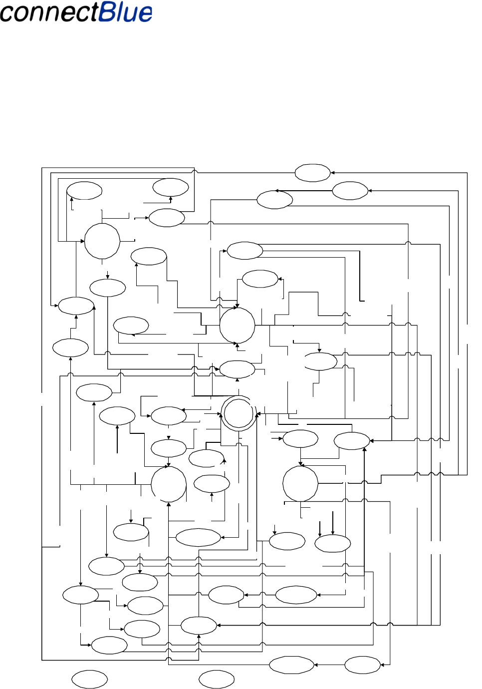
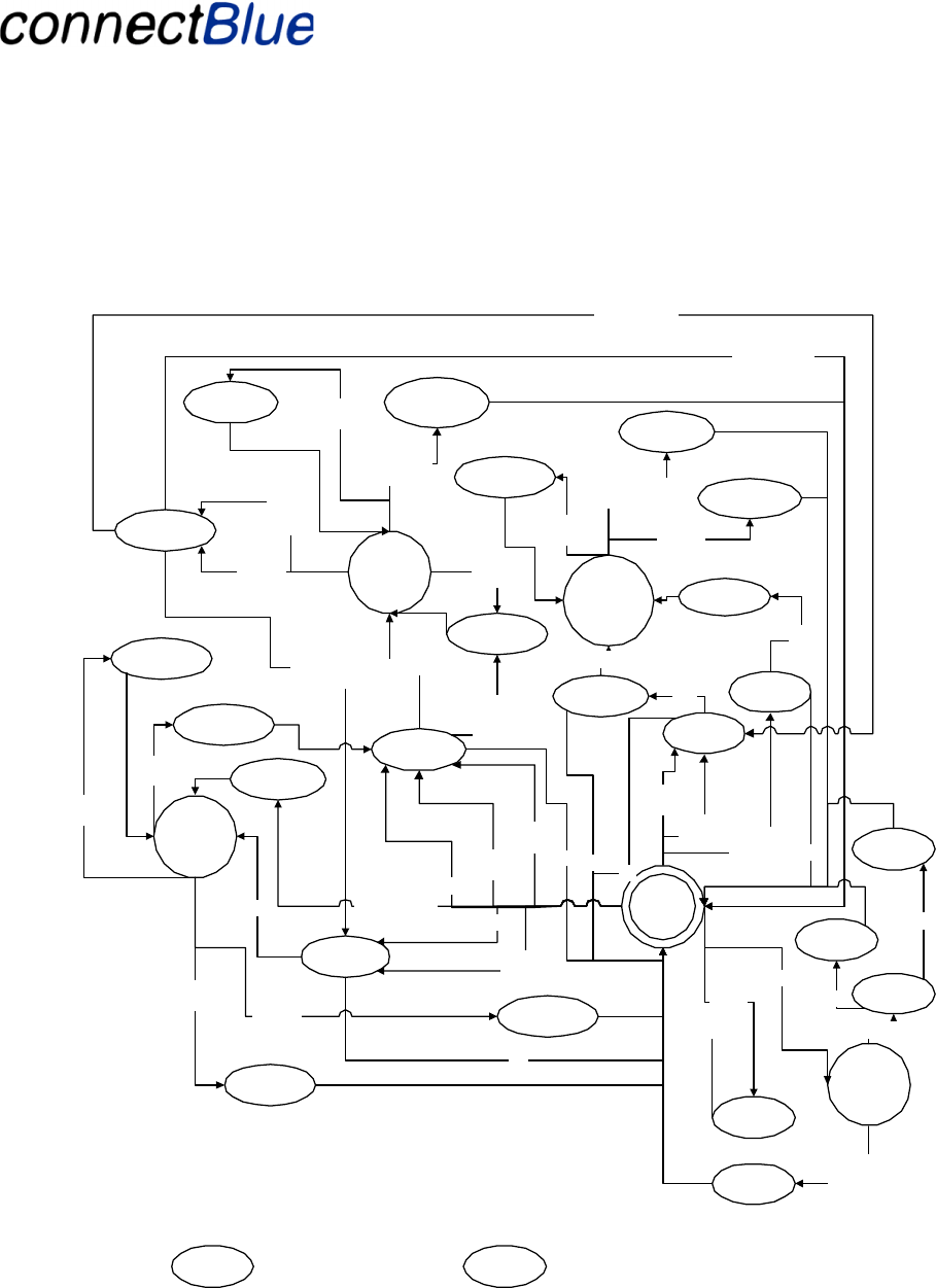
Appendix 2 – Receiver Operating State Chart
MF = 1
(short)
Prev state =
Intercom
Walkie-talkie
Connection
Request
Phone
Calling
Prev State = AV
MF = 1
(short)
Prev State
= Intercom
Operating
Idle
(LED = Idl e)
Phone
(LED =
Connect)
Ring
Ac cept Call
Phone Calling
MF = 1
(short)
PrevState =
Idle or
Walkie-talkie
Intercom
(LED =
Connect)
Initiate
Intercom
TO = 120 s
TI = 0->1
Fail
AV
(LED =
Connect)
Accept
AV
AV Request
Fail
Terminate
Intercom
TI=0 f or TO s
Prev St ate = Idle AV
Termination
Request
Terminate
Intercom
Phone
Calling
Phone Terminat e
Request
Accept Phone
Termination
Accept AV
Termination
Phone
Termination
MF =1
(long)
Prev St ate = Idle or
Walkie-talkie
Init iate AV
PrevState = AV
Intercom
Termination
Intercom
Terminated
Prev State = AV
Prev St ate = Idle
Timer = 5s
Second
Receiver? No
Yes
TI=0->1
Terminate AV
Second
Receiver?
Yes
No
Initiate
Intercom
TO = 10 s
Fail
Ring
Ac cept Call
Timer = 5s
IN D=Fail At all transitions marked "Fail"IND=Success At all transistions marked
"Success"
Terminate AV
MF = 1
(short)
Terminate
Intercom
TI = 0 f or TO sec
Prev State = AV
Intercom
Connection
Request
Terminate AV
Accept
Intercom Request
TO = 10 s
Accept
Intercom Request
TO = 120 s
Intercom
Connection
Request
Intercom
Connection
Request
Fail
Reject AV
Request
AV
Connection
Request
Reject AV
Request
TO = 10 s
AV
Connection
Request
TI=1 f or 8-20s
Walkie-talkie
(LED =
Connect)
Accept
Walkie-talkie
Request
Walkie-talkie
Connection
Request
Reject
Walkie-talkie
Request
Walkie-talkie
Connection
Request
Terminate
Walkie-talkie
Phone Calling
Walkie-talkie
Terminate
Request
Terminate AV
Ac cept Walk ie-
talkie
Termination
Reject AV
Request
Reject
Intercom
Request
Intercom
Connection
Request
AV
Connection
Request
Reject
Intercom
Request
Prevstate =
Intercom
Initiate
Intercom
Fail
PrevState = I dle or
Walkie-talkie
Prev state =
AV or Idle
Prev state =
Intercom
Walkie-talkie
Connection
Request
Terminate
Intercom
Request
Intercom
Termination
Granted
Denied
Request
Intercom
Termination
Granted
Denied
Accept
Intercom
Termination
Intercom
Termination
Request
TI = 0
for > TO s?
Prev s tate = Idle
Accept
Intercom
Termination
Prev state = AV
Reject
Intercom
Termination
No
MF = 1 (short)
Prev State =
Idle or
Walkie-talkie
MF = 1 (short)
Prev State = AV
MF = 1 (short)
Prev State =
Intercom
TI=1 f or 8-20s
Utfärdare / Issued by Datum / Date Beteckning / Ref. Sida / Page
Mats Andersson 2005-03-30 cBProject-0503-17 (1) 26 (27)
Ärende / Subjekt Godkänd av / Approved by
WCS Module User Manual
Template update: 00-12-01
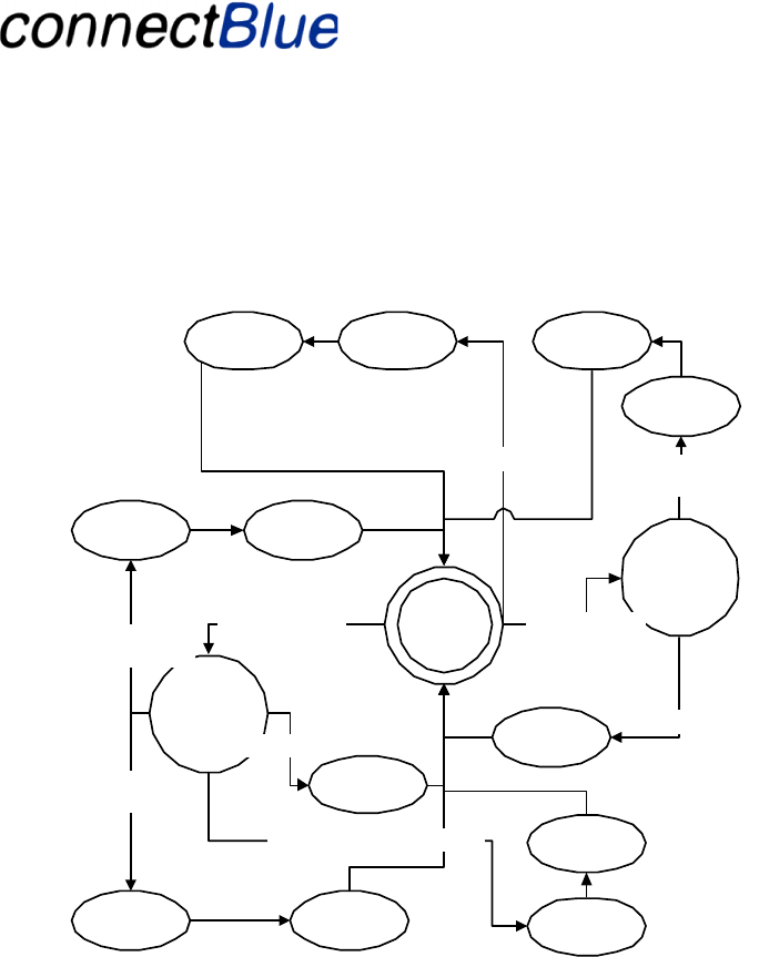
Appendix 3 – Receiver Setup State Chart
Setup Idle
(LED = Setup)
Pairable
(LED = Pair)
Vol + = 1 (short)
Timer = 60s IND = Fail
Store Phone
Information
Pair with
phone succeded
IND = Success
Store Base
Information
Pair with
base succeded
IND = Success Store Receiver
Information
IND = Success
Pair with receiv er succeded
Pairing
(LED = Pair)
Pairing with receiv er
succeded
Store Reciver
Information
IND = Success
Vol + = 1 (long)
Erase Pairing
Vol - = 1 (long)
IND = Success
IND = Fail
Timer = 60s
Utfärdare / Issued by Datum / Date Beteckning / Ref. Sida / Page
Mats Andersson 2005-03-30 cBProject-0503-17 (1) 27 (27)
Ärende / Subjekt Godkänd av / Approved by
WCS Module User Manual
Template update: 00-12-01
Appendix 4 – Base Unit State Chart
Idle
(LED = Idle)
AV (SR)
(LED =
Connect)
AV (FR)
(LED =
Connect)
Init iate AV (FR )
Initiate AV (SR)
MF=0->1
Success
MF=
0->1
Success
Fail
Accept AV (FR)
Termination
AV Termination
Request
Accept AV (SR)
Terminattion
AV Termination
Request Terminate AV (SR)
MF=1->0
or
TI=0->1
Terminate AV (FR)MF=1->0
Pairing
(LED=Pair)
Vol+=1
St ore SR
Information
IND=Fail
Timer=60s
or
2 Receivers
paired
Fail
Accept AV (SR)
Connection
AV Connection
Request
MF =1 f or
30s
MF = 1 f o r
30s
Accept AV (FR)
Connection
AV Connection
Request
Walkie-talkie
(LED =
Connect)
TI = 0->1
Initiate Walkie-
talkie
Success
Terminate AV (FR)
TI =
0->1
Terminate Walkie-
talkie
TI = 1->0
and
NI = 0
Prev s tat e = Idle
or
MF = 0
Prev state = AV
and
MF = 1
Ac cept Walk ie-
talkie
Terminattion
Walkie-talkie
Termination
Request
FailTI = 1 f or
5s
Send GPS
Info
NI =
0->1
Send GPS
Info
NI =
0->1
Success
and
NI = 1
NI =
0->1
NI = 1->0
and
TI = 0
FR = First Receiver
SR = Second Receiver
Second
Receiver?
Yes
No
Second
Receiver?
Yes
No
Send GPS
Info
NI =
0->1
I ND =Fail At all t ransitions marked "F ail"IND=Success At all transistions marked
"Success"
Prev state = AV
and
MF = 1
Erase Pairing
Vol-=1
Success
Second
Receiver?
Yes
Success
Store FR
Information
No
Reject AV
Connection AV Connection
Request