u blox Malmo 090103L Serial Port Adapter User Manual Part 2
u-blox Malmo AB Serial Port Adapter Users Manual Part 2
UserManual.wiki
>
u blox Malmo
>
090103L User Manual
>
Users Manual Part 2
Contents
1.
Users Manual Part 1
2.
Users Manual Part 2
Users Manual Part 2
Navigation menu
Upload a User Manual
Namespaces
Wiki Guide
HTML
PDF
Info
Views
User Manual
Discussion / Help
Navigation
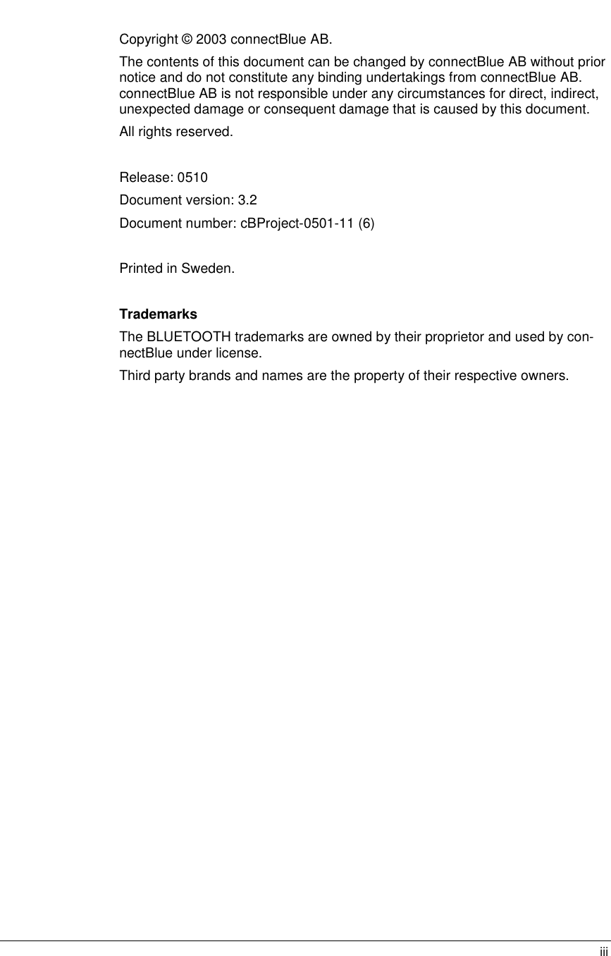

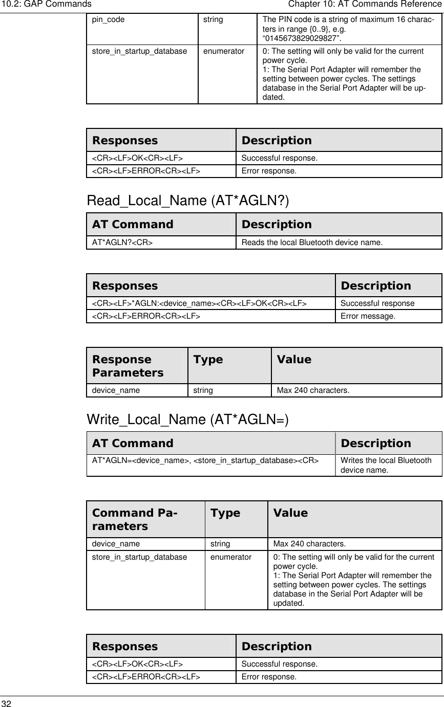
![10.2: GAP Commands Chapter 10: AT Commands Reference 33 Model Constraint cB-OEMSPA311 cB-OEMSPA331 cB-OEMSPA312 cB-OEMSPA332 The name is limited to a maximum of 31 characters. Read_Local_COD (AT*AGLC?) AT Command Description AT*AGLC?<CR> Reads the Local Class Of Device code. Responses Description <CR><LF>*AGLC:<cod><CR><LF>OK<CR><LF> Successful response. <CR><LF>ERROR<CR><LF> Error response. Response Parameters Type Value cod integer Valid values for this parameter are specified in the Bluetooth Assigned Numbers Document, www.bluetooth.com. The parameter has been divided into three segments, a service class segment, a major device class segment and a minor device class segment (bits 2-7). Extract from the Bluetooth Assigned Numbers Document: Service class (bit mask, bits 13-23): Bit 16: Positioning (Location identification) Bit 17: Networking (LAN, Ad hoc, etc) Bit 18: Rendering (Printing, Speaker, etc) Bit 19: Capturing (Scanner, Microphone, etc) Bit 20: Object Transfer (v-Inbox, v-Folder, etc) Bit 21: Audio (Speaker, Microphone, Headset service, etc) Bit 22: Telephony (Cordless telephony, Modem, Headset service) Bit 23: Information (WEB-server, WAP-server, etc) Major device class (number, bits 12-8): 00000: Miscellaneous 00001: Computer (desktop, notebook, PDA, etc)00010: Phone (cellular, cordless, modem, etc) 00011: LAN/Network Access point 00100: Audio/Video (headset, speaker, stereo, video display, VCR) 00101: Peripheral (mouse, joystick, keyboards) 00110: Imaging (printing, scanner, camera, etc)11111: Uncategorized, specific device code not specified For the minor device class field please refer to [1]. Write_Local_COD (AT*AGLC=) AT Command Description AT*AGLC=<cod>, <store_in_startup_database><CR> Writes the Local Class Of Device code.](https://usermanual.wiki/u-blox-Malmo/090103L.Users-Manual-Part-2/User-Guide-601240-Page-33.png)