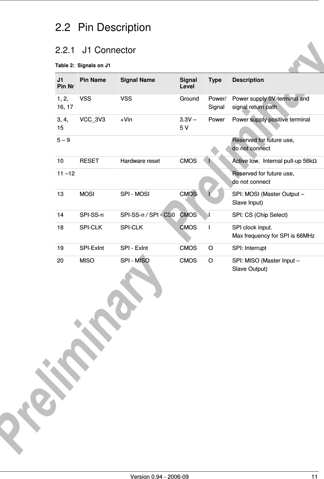
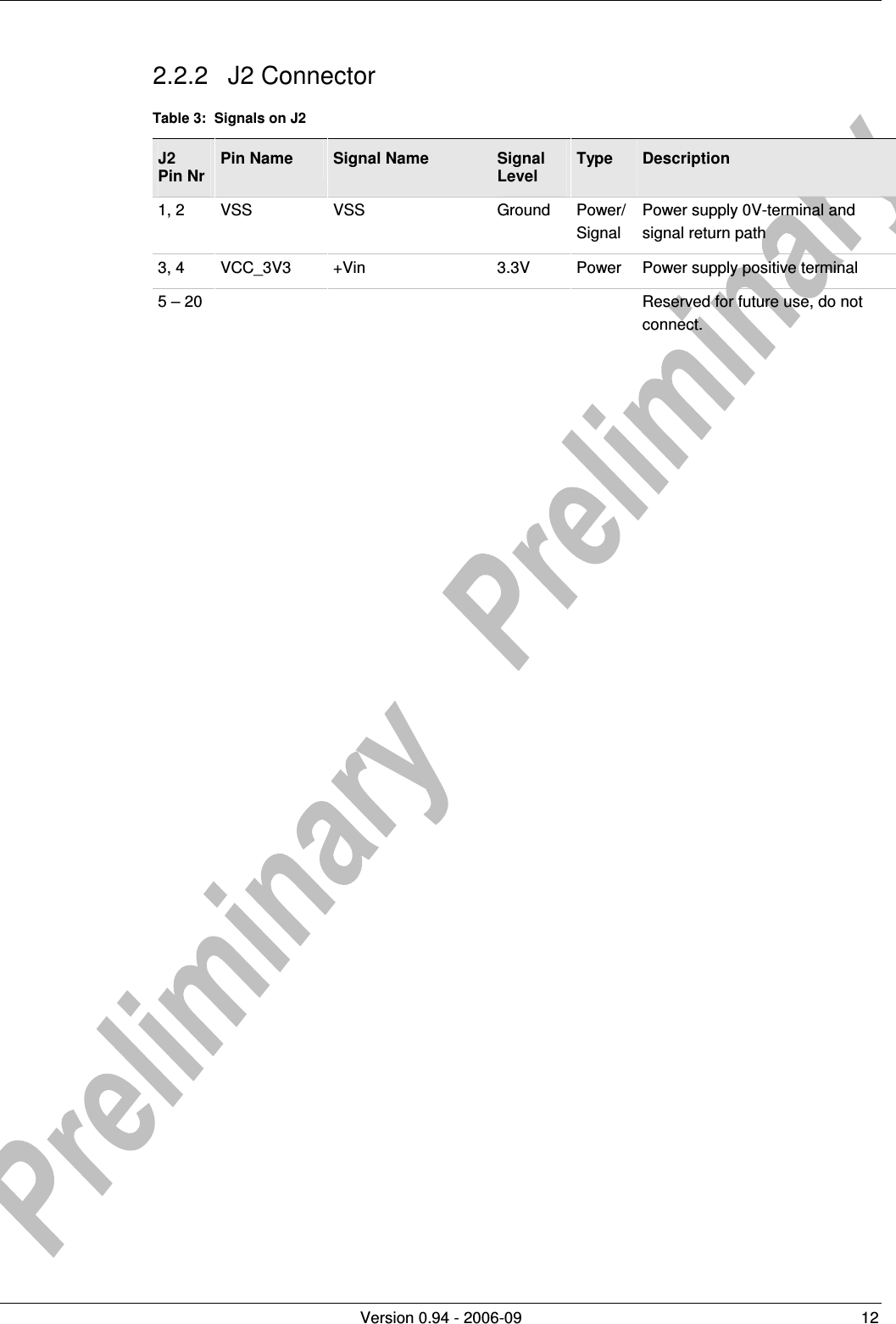
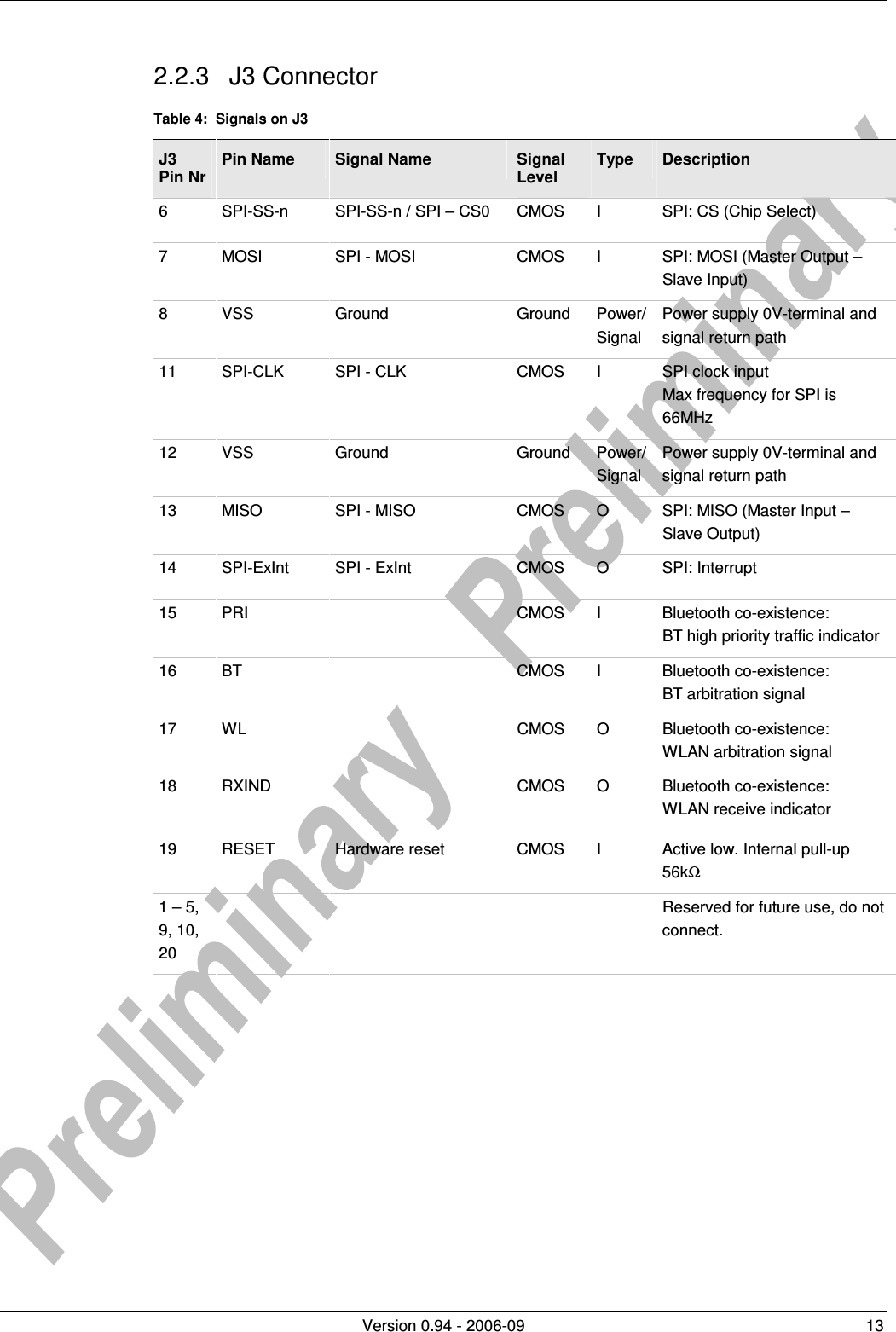
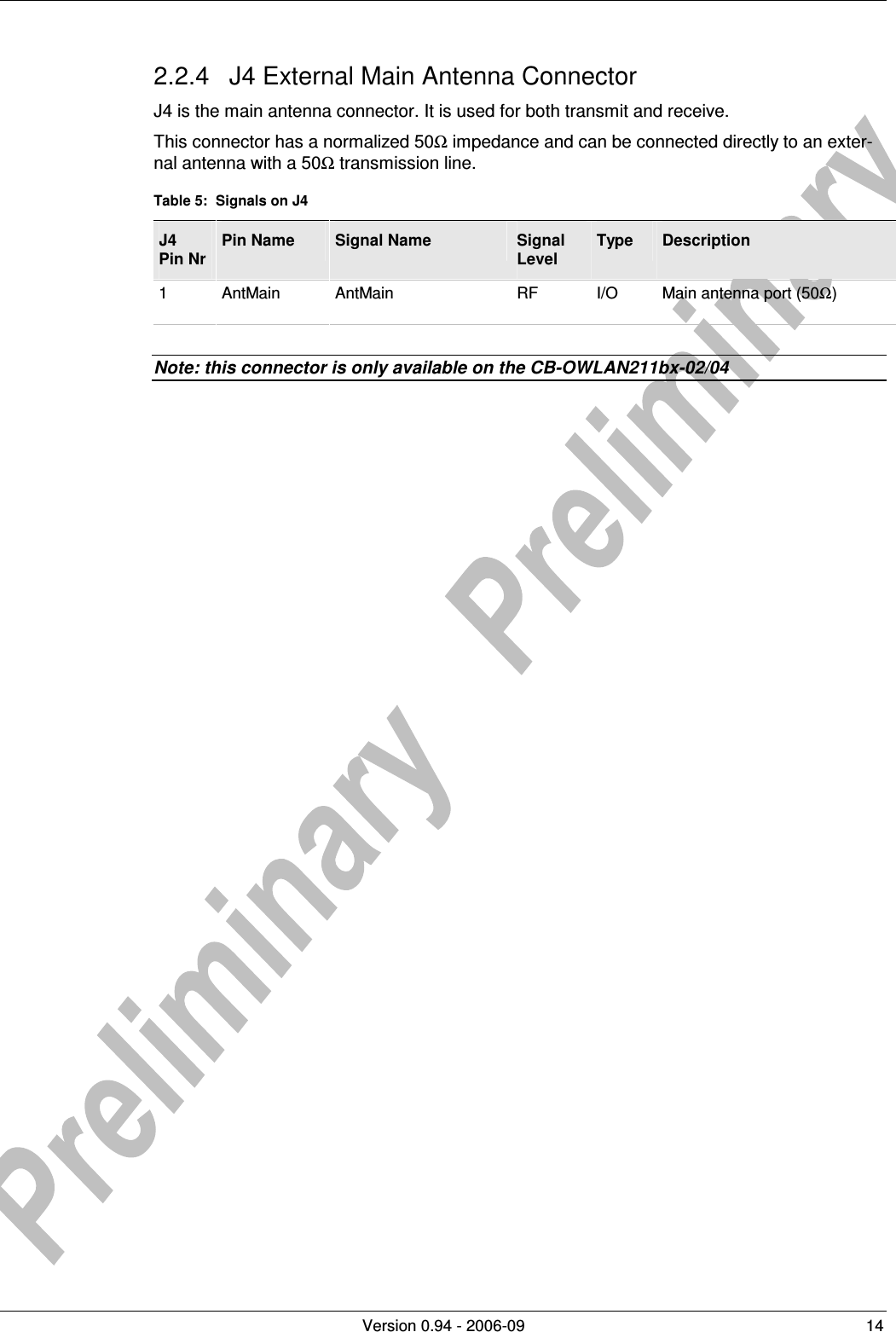
u blox Malmo 090402 Wireless Communication System Module User Manual EM Datasheet OWLAN211b
u-blox Malmo AB Wireless Communication System Module EM Datasheet OWLAN211b
UserManual.wiki
>
u blox Malmo
>
090402 User Manual
Integration Manual
Navigation menu
Upload a User Manual
Namespaces
Wiki Guide
HTML
PDF
Info
Views
User Manual
Discussion / Help
Navigation
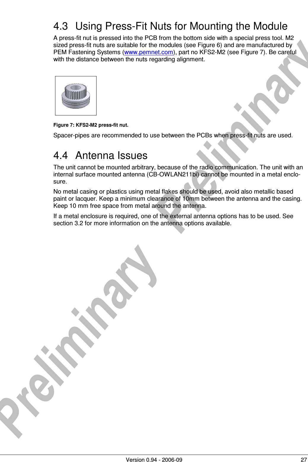
![Version 0.94 - 2006-09 24 4 Mounting Information 4.1 Board Outlines 4.1.1 cB-0904 Figure 5: cB-0904 dimensions [mm].](https://usermanual.wiki/u-blox-Malmo/090402/User-Guide-730426-Page-24.png)
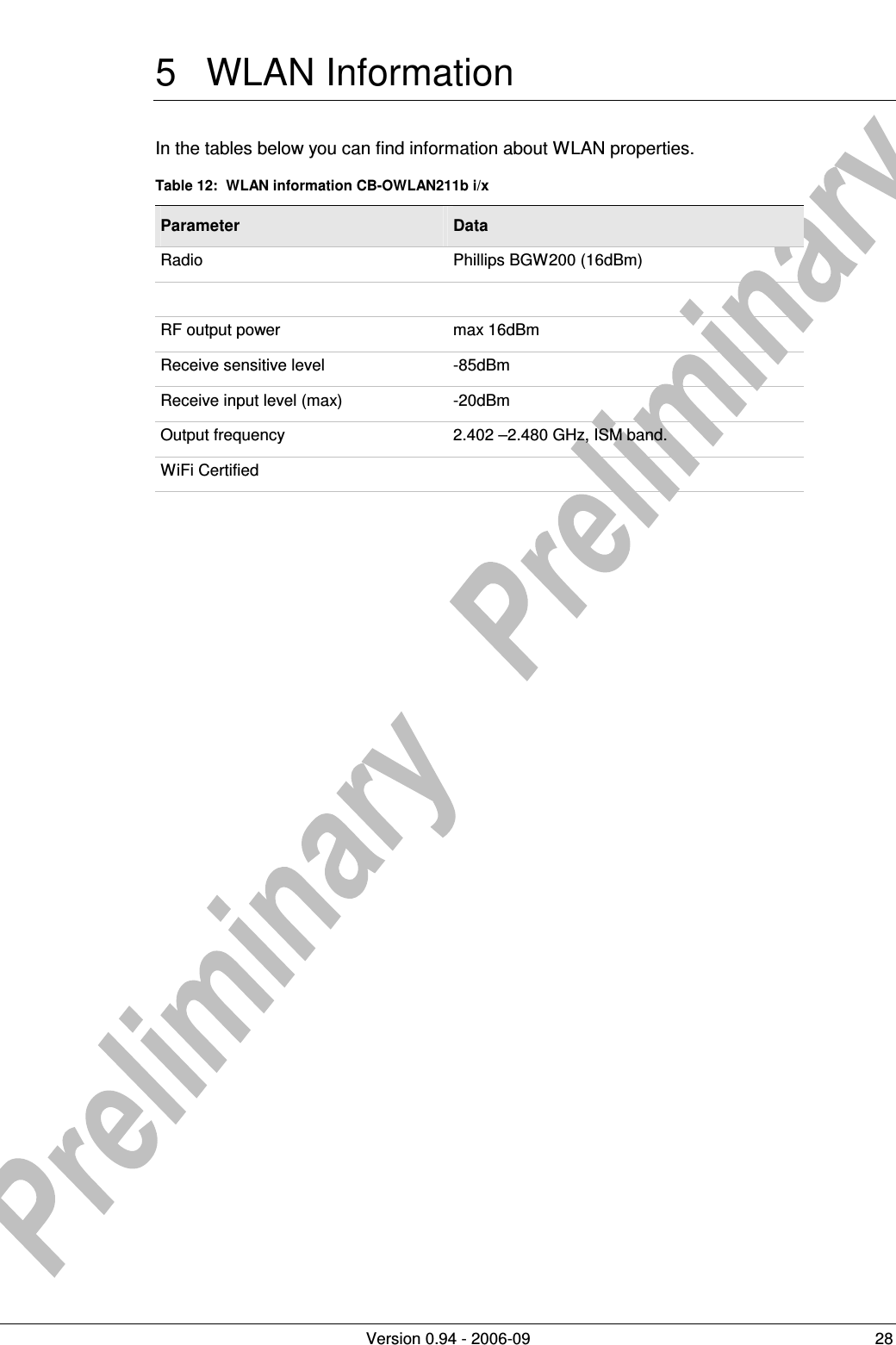
![Version 0.94 - 2006-09 26 Figure 6: Host PCB layout [mm] for double row connector.](https://usermanual.wiki/u-blox-Malmo/090402/User-Guide-730426-Page-26.png)