u blox Malmo 090402 Wireless Communication System Module User Manual EM Datasheet OWLAN211b
u-blox Malmo AB Wireless Communication System Module EM Datasheet OWLAN211b
Integration Manual
INDUSTRIAL BLUETOOTH™
OWLAN211b i/x™
cB-0904
Electrical & Mechanical Datasheet
OWLAN211b i/x™
cB-0904
Electrical & Mechanical Datasheet
Copyright © 2006 connectBlue AB
The contents of this document can be changed by connectBlue AB without prior no-
tice and do not constitute any binding undertakings from connectBlue AB. con-
nectBlue AB is not responsible under any circumstances for direct, indirect, unex-
pected damage or consequent damage that is caused by this document.
All rights reserved.
Release: 2006-09
Document version: 0.94
Document number: cBProject-0505-19
Printed in Sweden.
Trademarks
Registered trademarks from other companies are: Microsoft™, Windows™, Win-
dows NT™, Windows 2000™, Windows CE™, Windows ME™, are registered
trademarks from Microsoft Corporation.

Version 0.94 - 2006-09 4
Contents
1 Introduction 5
1.1
Related Documents ...........................................................................5
1.2
Product Variants ................................................................................6
1.3
Block Diagram cB-0904 .....................................................................8
2 Electrical Interface and Connectors 9
2.1
Pin Numbering .................................................................................10
2.2
Pin Description .................................................................................11
2.3
Characteristics .................................................................................16
2.4
Hardware Reset ...............................................................................18
2.5
Power Control ..................................................................................18
3 Antennas 19
3.1
Surface Mounted Antenna (internal)................................................19
3.2
External antennas ............................................................................20
4 Mounting Information 24
4.1
Board Outlines .................................................................................24
4.2
Using the J2/J3 Board-to-Board Connectors ...................................25
4.3
Using Press-Fit Nuts for Mounting the Module ................................27
4.4
Antenna Issues ................................................................................27
5 WLAN Information 28
6 Regulatory Information 29
6.1
Declaration of Conformity TBD ........................................................29
6.2
Safety Compliance...........................................................................30
6.3
FCC and IC Compliance ..................................................................30
6.4
UL listing information .......................................................................32
6.5
Compliance with RoHS directive......................................................32
7 Guidelines for Efficient and Safe Use 33
7.1
General 33
7.2
Product Care ....................................................................................33
7.3
Radio Frequency Exposure .............................................................33
7.4
Electronic Equipment .......................................................................34
7.5
Potentially Explosive Atmospheres..................................................34
7.6
Power Supply...................................................................................34
Appendix A - Application Notes 35
A.1
Step-by-Step Guide .........................................................................35
A.2
Design Examples .............................................................................36
A.3
Test Points .......................................................................................38
Version 0.94 - 2006-09 5
1 Introduction
1.1 Related Documents
There are some documents related to the OWLAN211b i/x module (see Figure 1):
- The OWLAN211b User Manual contains information on how to use the OWLAN211b
module. Study this document before moving on to the others.
- The OWLAN211b Host Driver Documentation contains description of the Host driver
and it’s requirements.
- The OWLAN211b Electrical & Mechanical Datasheet (this document) contains
important information about the OWLAN211b module. Read this document if you plan to
mount the OWLAN211b module on your design.
Figure 1: CB-OWLAN211b documents
OWLAN211b i/x
User Manual
OWLAN211b i/x
Host Driver Documentation
OWLAN211b i/x
Electrical & Mechanical Datasheet

Version 0.94 - 2006-09 6
1.2 Product Variants
This Electrical and Mechanical datasheet contains information about the variants of
OWLAN211b modules based on the PCB cB-0904.
This document makes references to the OWLAN Module ID, not the Product Name
(see Table 1).
Table 1: Product variants
Product Name Module ID /
FCC ID
WLAN Type Description
CB-OWLAN211b i-02 cB-0095-01
PVH090402
11 Mbit DSSS
16 dBm (40 mW)
OWLAN211b with internal
antenna, 2mm pin connector
Internal antenna
CB-OWLAN211b i-04 cB-0096-01
PVH090402
11 Mbit DSSS
16 dBm (40 mW)
OWLAN211b with internal
antenna, no pin connector
Note: Not available from
stock
CB-OWLAN211b x-02 cB-0097-01
PVH090402
11 Mbit DSSS
16 dBm (40 mW)
OWLAN211b with external
antenna, 2mm pin connec-
tor. Receive diversity sup-
ported.
External antenna
CB-OWLAN211b x-04 cB-0098-01
PVH090402
11 Mbit DSSS
16 dBm (40 mW)
OWLAN211b with external
antenna, no pin connector.
Receive diversity supported.
Note: Not available from
stock

Version 0.94 - 2006-09 7
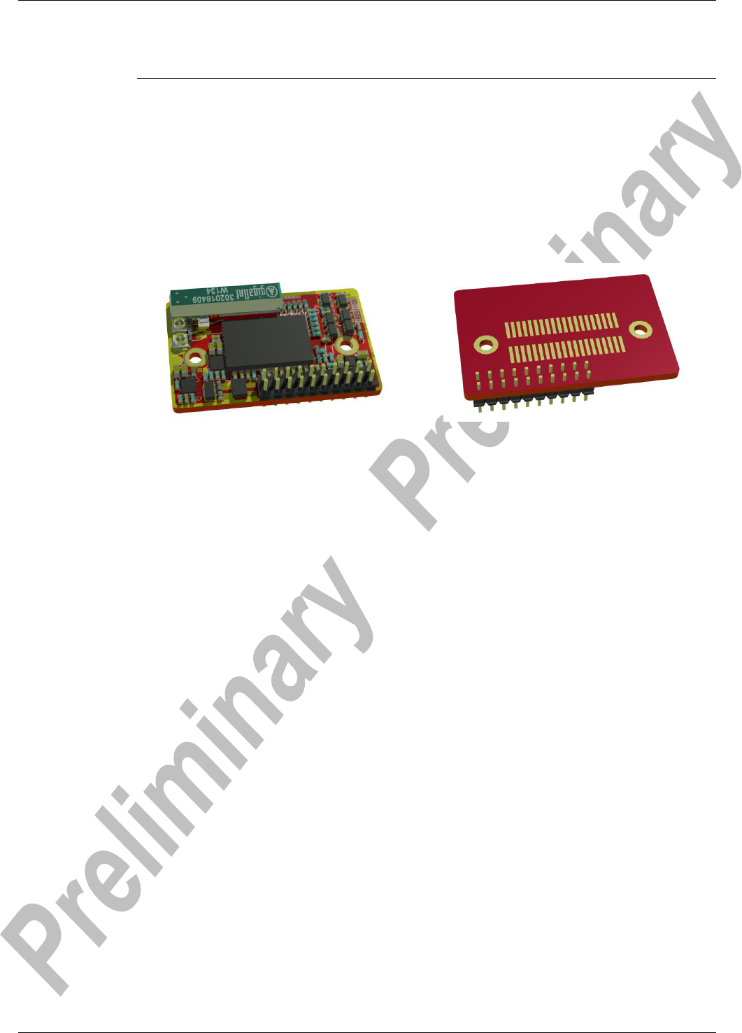
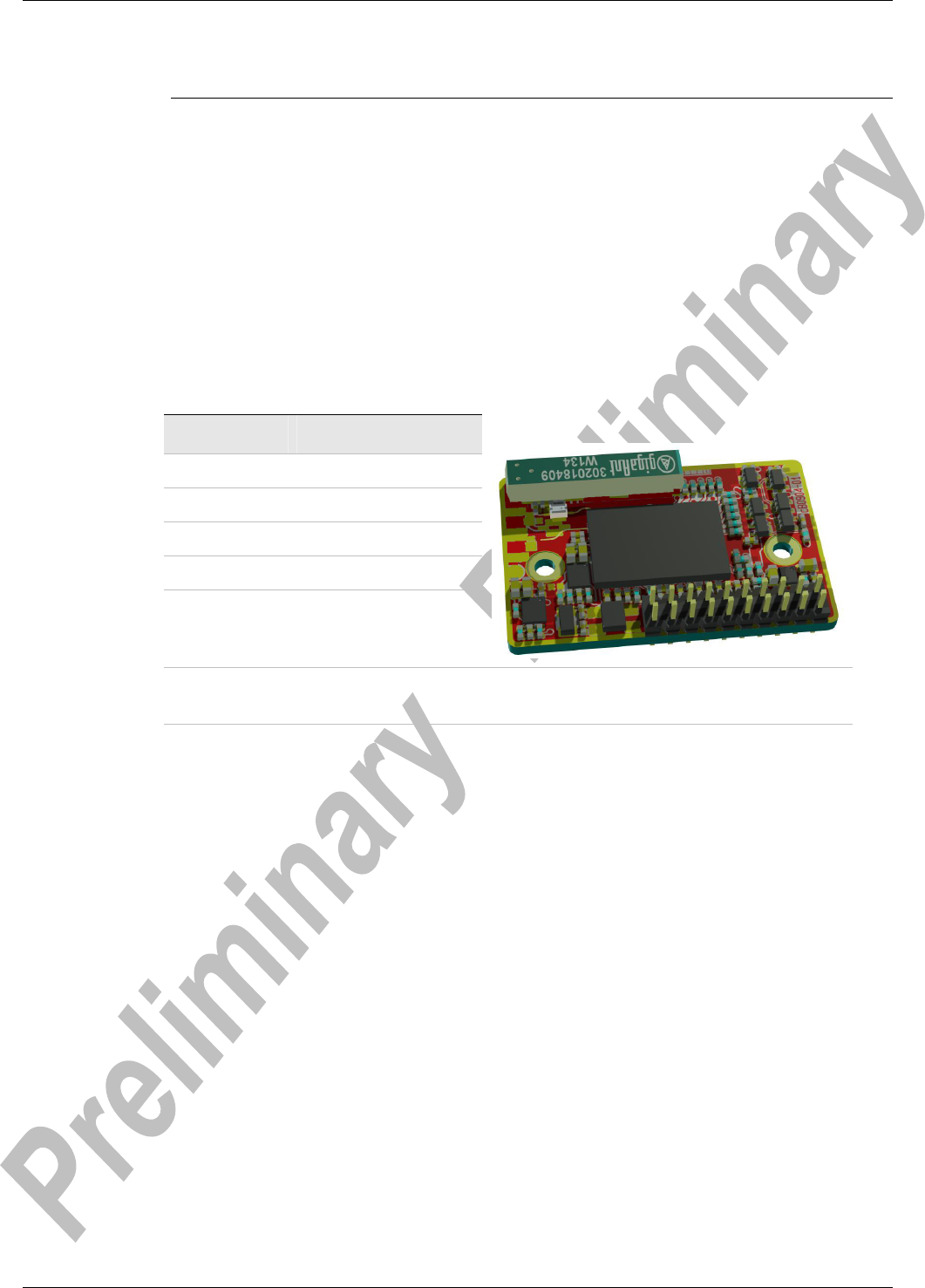
1.2.1 cB-0904
cB-0904 is a small size WLAN module based on the Phillips BGW200 system in package
(SiP). The modules are available in many different antenna combinations. See Picture 1 – 2
for some of the available models. All models are described in Table 1.
Picture 1: CB-OWLAN211b x-02 Module with 2
external antenna connectors and 2mm pin con-
nector
Picture 2: CB-OWLAN211bi-04 Module with in-
ternal antenna
Version 0.94 - 2006-09 8
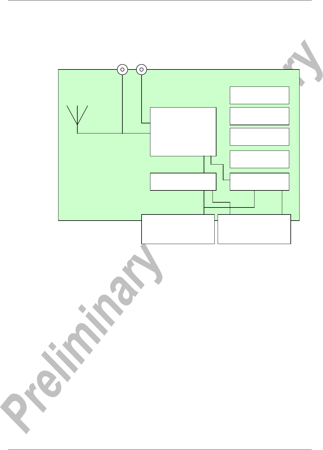
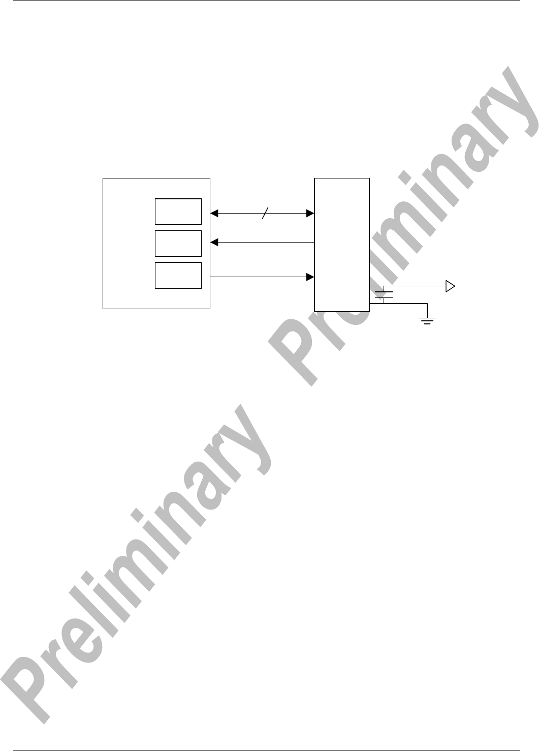
1.3 Block Diagram cB-0904
Figure 2: Block diagram of cB-0904
J1
2x10 pinlist connector
(2,0 mm pitch, 20 pins)
J2/J3
One-piece-part connector pads
(1,0 mm pitch, 40 pads)
BGW200EG/01
Low-Power WLAN SiP
Baseband/MAC
RF Transceiver
Power Amplifier
Voltage Regulator (1.8VDC)
Voltage Regulator (2.8VDC)
Voltage Regulator (3.3VDC)
Crystal (44MHz, 10 ppm)
Buffers Reset Logic
Internal SMD antenna
*Only on internal antenna versions, no
diversity support
Coaxial Connectors (U.FL)
*Only on external antenna versions
J4
J5
AUX
*Adds diversity support
Main
Version 0.94 - 2006-09 9
2 Electrical Interface and Connectors
This section describes the signals available on the module interface connectors. There are
two ways to connect to the OWLAN211b module:
• Via the 2x10-pin 2mm header connector J1 (see Picture 3).
• Via the 2x20-pin 1mm pitch board-to-board (one piece part) connectors, J2 through
J3. The J2 to J3 connectors on the OWLAN211b module exist on the module only as
a mating PCB-layout pattern (see Picture 4).
Picture 3: 2x20 2mm pinlist connector, J1. Picture 4: 1-mm pitch board-to-board connector, J2
and J3.
Version 0.94 - 2006-09 10
2.1 Pin Numbering
2.1.1 J1, J4, and J5 Connectors
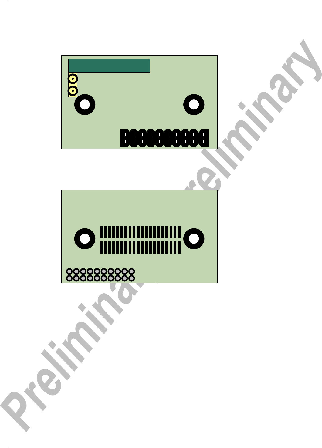
Figure 3: Top view of the PCB with the pinning of the J1 connector.
2.1.2 J2 and J3 Connectors
Figure 4: Bottom view of the PCB with the pinning of the J2 and J3 pads connector.
Top View
1
2
19
20
J1
Bottom View
1 20
20 1
J2
J3
SMD Antenna
J4
J5

Version 0.94 - 2006-09 11
2.2 Pin Description
2.2.1 J1 Connector
Table 2: Signals on J1
J1
Pin Nr
Pin Name Signal Name Signal
Level
Type Description
1, 2,
16, 17
VSS VSS Ground Power/
Signal
Power supply 0V-terminal and
signal return path
3, 4,
15
VCC_3V3 +Vin 3.3V –
5 V
Power Power supply positive terminal
5 – 9 Reserved for future use,
do not connect
10 RESET Hardware reset CMOS I Active low. Internal pull-up 56kΩ
11 –12
Reserved for future use,
do not connect
13 MOSI SPI - MOSI CMOS I SPI: MOSI (Master Output –
Slave Input)
14 SPI-SS-n SPI-SS-n / SPI - CS0
CMOS I SPI: CS (Chip Select)
18 SPI-CLK SPI-CLK CMOS I SPI clock input.
Max frequency for SPI is 66MHz
19 SPI-ExInt SPI - ExInt CMOS O SPI: Interrupt
20 MISO SPI - MISO CMOS O SPI: MISO (Master Input –
Slave Output)

Version 0.94 - 2006-09 12
2.2.2 J2 Connector
Table 3: Signals on J2
J2
Pin Nr
Pin Name Signal Name Signal
Level
Type Description
1, 2 VSS VSS Ground Power/
Signal
Power supply 0V-terminal and
signal return path
3, 4 VCC_3V3 +Vin 3.3V Power Power supply positive terminal
5 – 20 Reserved for future use, do not
connect.

Version 0.94 - 2006-09 13
2.2.3 J3 Connector
Table 4: Signals on J3
J3
Pin Nr
Pin Name Signal Name Signal
Level
Type Description
6 SPI-SS-n SPI-SS-n / SPI – CS0 CMOS I SPI: CS (Chip Select)
7 MOSI SPI - MOSI CMOS I SPI: MOSI (Master Output –
Slave Input)
8 VSS Ground Ground Power/
Signal
Power supply 0V-terminal and
signal return path
11 SPI-CLK SPI - CLK CMOS I SPI clock input
Max frequency for SPI is
66MHz
12 VSS Ground Ground Power/
Signal
Power supply 0V-terminal and
signal return path
13 MISO SPI - MISO CMOS O SPI: MISO (Master Input –
Slave Output)
14 SPI-ExInt SPI - ExInt CMOS O SPI: Interrupt
15 PRI CMOS I Bluetooth co-existence:
BT high priority traffic indicator
16 BT CMOS I Bluetooth co-existence:
BT arbitration signal
17 WL CMOS O Bluetooth co-existence:
WLAN arbitration signal
18 RXIND CMOS O Bluetooth co-existence:
WLAN receive indicator
19 RESET Hardware reset CMOS I Active low. Internal pull-up
56kΩ
1 – 5,
9, 10,
20
Reserved for future use, do not
connect.

Version 0.94 - 2006-09 14
2.2.4 J4 External Main Antenna Connector
J4 is the main antenna connector. It is used for both transmit and receive.
This connector has a normalized 50Ω impedance and can be connected directly to an exter-
nal antenna with a 50Ω transmission line.
Table 5: Signals on J4
J4
Pin Nr
Pin Name Signal Name Signal
Level
Type Description
1 AntMain AntMain RF I/O Main antenna port (50Ω)
Note: this connector is only available on the CB-OWLAN211bx-02/04

Version 0.94 - 2006-09 15
2.2.5 J5 External Auxiliary Antenna Connector
J5 is the auxiliary antenna connector. It is used only for receiving and if the unit is configured
for diversity mode. The unit never transmits data using this antenna connector.
This connector has a normalized 50Ω impedance and can be connected directly to an exter-
nal antenna with a 50Ω transmission line.
Table 6: Signals on J5
J4
Pin Nr
Pin Name Signal Name Signal
Level
Type Description
1 AntAux AntAux RF I Auxiliary antenna port (50Ω)
Note: this connector is only available on the CB-OWLAN211bx-02/04
Version 0.94 - 2006-09 16
2.3 Characteristics
2.3.1 Power supply
Table 7: Power supply
Symbol Parameter Value Unit
Min 3.3
V VCC_3V3 Power supply
Max 5.0
V
Table 8: Current consumption
Symbol Mode Value Unit
ICC @ VCC 4.0V Reset Average 20
µA
Idle, firmware not loaded Average 24
mA
Idle, active mode Average 157
mA
Connected, active mode Average 160
mA
Connected, sleep mode Average 3
mA
Connected, active mode,
data transfer
Max 350
mA
Connected, sleep mode,
data transfer
Max 350
mA

Version 0.94 - 2006-09 17
2.3.2 Input/Output signals
Table 9: Input/output signals
Symbol Parameter Value Unit
Min -0.3
V V
IN
Low Logic LOW level input voltage on all logic
Max 0.85
V
Min 2.1
V V
IN
High Logic HIGH level input voltage
Max 3.3
V
V
OUT
Low Logic LOW level output voltage Max 0.4
V
V
OUT
High Logic HIGH level output voltage Min 2.5
V
I
GPIO
Sink and source current Max 4
mA
C
GPIO
Input capacitance Typ 8
pF
V
thl(POR)
Lower Power-on reset threshold voltage Typ 0.4
V
V
thu(POR)
Upper Power-on reset threshold voltage Typ 2
V
Note: MOSI, SPI-CLK and SPI-SS are 5 V tolerant
2.3.3 Environmental
Table 10: Temperatures characteristics
Parameter Product Variant Value Unit
Min CB-OWLAN211b i/x-02
CB-OWLAN211b i/x -04 -40
°C Storage temperature
Max CB-OWLAN211b i/x -02
CB-OWLAN211b i/x -04 +125
°C
Min CB-OWLAN211b i/x -02
CB-OWLAN211b i/x -04
-30
°C Operating temperature
Max CB-OWLAN211b i/x -02
CB-OWLAN211b i/x -04
+85
°C

Version 0.94 - 2006-09 18
2.4 Hardware Reset
A hardware reset input is available on the J1 and J3 connectors (see section 2.1). An exter-
nal reset source must be open drain or collector. The RESET pin is pulled-up internally with
56kΩ.
See example in A.2.2
2.5 Power Control
The CB-OWLAN211b module can be put in one of four power modes.
• Active mode – no power saving is done.
• Sleep mode – power saving. The module is held in low power mode and only listens
and responds to beacons.
• Powers save mode – Maximum power save. The device is incapable of transmitting
or receiving data.
• Reset mode – The RESET pin is held down. As long as the RESET pin is held low
the internal power regulators are shut off. This will ensure maximum power save.
Version 0.94 - 2006-09 19
3 Antennas
There are 2 different antenna options available:
• An internal surface mounted (SMD) antenna.
• An “external antenna” should be connected to a U.FL connector. Many different “ex-
ternal antennas” are available.
See section 4.1 for more information on antenna placement.
This chapter gives an overview of the qualities of the different antenna options.
3.1 Surface Mounted Antenna (internal)
The unit cannot be mounted in a metal-shielded enclosure with this antenna.
Part Number OWLAN211i
Antenna name Mica 2.4 GHz
Manufacture gigaAnt
Polarization Linear
Gain (Typ) 2.5 dBi
Antenna Size
(LxWxH)
20.5x3.6x3.3 mm
Comment The antenna gain is dependent of the mounting of the module. See section
4.4 for mounting the module considering the antenna.
Version 0.94 - 2006-09 20
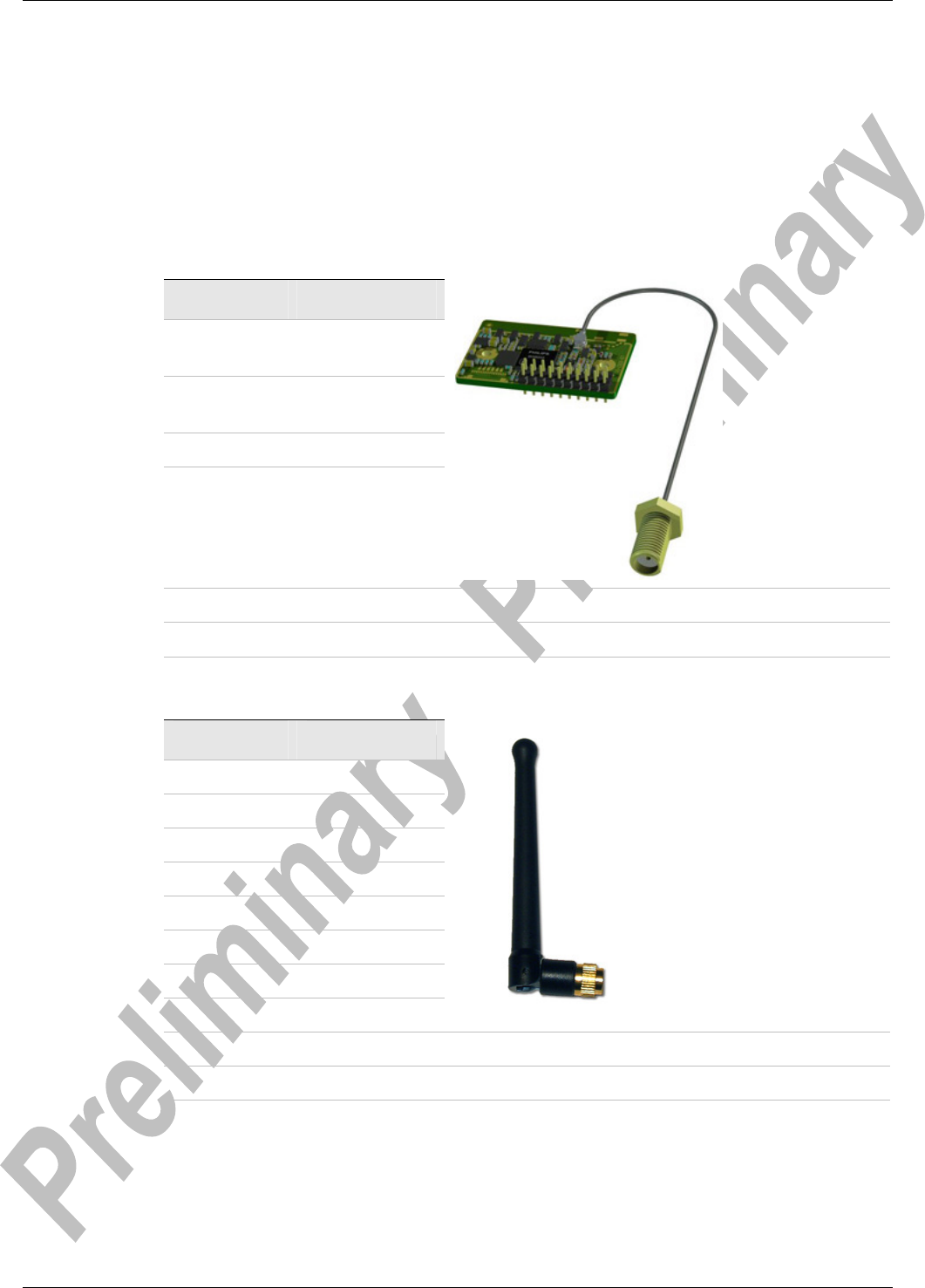
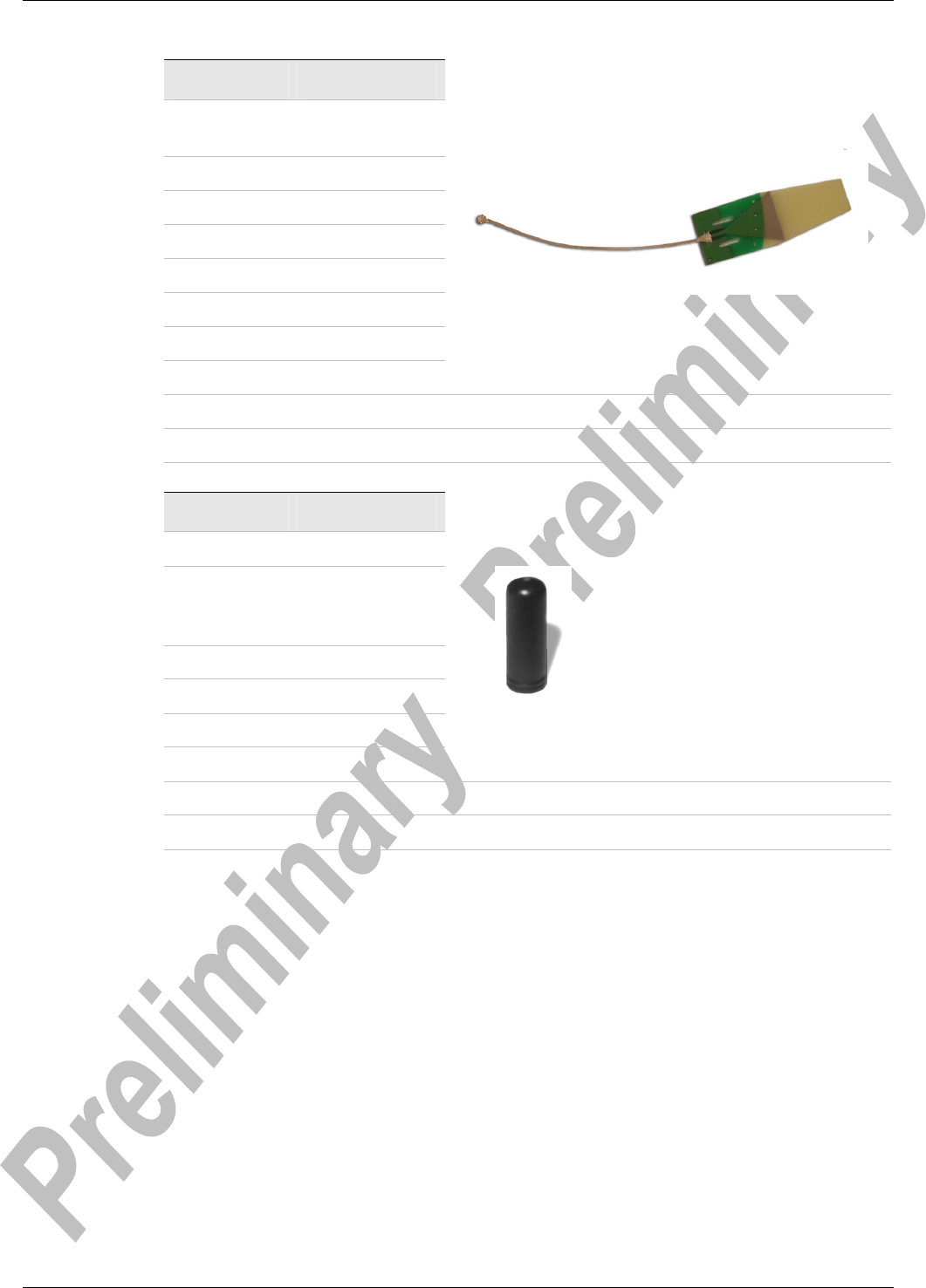
3.2 External antennas
The external antennas are connected to the board through a U.FL connector. Some of the
antennas are connected directly to the U.FL connector of the board and some are connected
using an SMA connected through a short U.FL to SMA adapter cable.
Note: Antennas with SMA connectors are not approved for use in USA or Canada due to
FCC regulations.
3.2.1 Antenna Accessories
Part Number cB-ACC-18
Name U.FL to SMA
adapter cable
Connector U.FL and
SMA female
Cable length 120 mm
Cable loss Less than 0.5dBm
Comment The SMA connector may be mounted in a panel.
Approval Not approved for use in the US and Canada.
3.2.2 Antennas
Part Number cB-ACC-16
Name WCR-2400-SMA
Manufacture Centurion
Type ½ wave dipole
Polarization Vertical
Gain +2.5dBi
Size 100 mm
Connector SMA male
Comment To be mounted on the U.FL to SMA adapter cable.
Approval Not approved for use in the US and Canada.
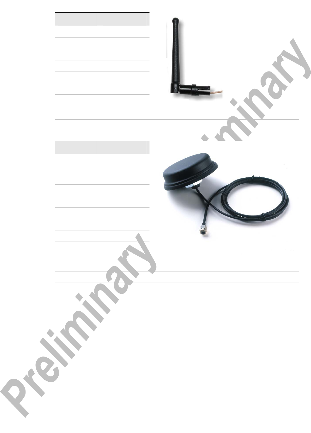
Version 0.94 - 2006-09 21
Part Number cB-ACC-27
Name WCR-2400-IP04
Manufacture Centurion
Type ½ wave dipole
Polarization Vertical
Gain +2.0dBi
Size 108 mm (Straight)
Connector U.FL connector
Comment To be mounted on the U.FL connector on the PCB.
Approval Approved for use in the US and Canada
Part Number cB-ACC-17
Name Reel planTec
Bluetooth m70
Manufacture Reel
Size (∅xH) 75x20 mm
Gain +1dBi
Mounting M16x13.6 mm
Cable length 3 m
Connector SMA male
Other info Waterproof (IP67)
Comment To be mounted on the U.FL to SMA adapter cable.
Approval Not approved for use in the US and Canada
Version 0.94 - 2006-09 22
Part Number cB-ACC-19
Name Microblue
CAP24235
Manufacture Centurion
Type Microstrip
Polarization Linear
Gain +1.5dBi
Size 21x60 mm
Cable length 200 mm
Connector U.FL
Comment Connected directly to the U.FL connector on OEM board.
Approval Approved for use in the US and Canada
Part Number cB-ACC-23
Name Mobile Mark Stub
Manufacture Mobile Mark
Communications
Antennas
Type ¼ wave dipole
Polarization Vertical
Gain 0 dBi
Connector SMA male
Comment To be mounted on the U.FL to SMA adapter cable
Approval Not approved for use in the US and Canada

Version 0.94 - 2006-09 23
Part Number cB-ACC-21
Name Rugged SMA
Manufacture Radiall/Larsen
Type ½ wave dipole
Polarization Vertical
Gain 2 dBi
Connector SMA male
Comment To be mounted on the U.FL to SMA adapter cable
Approval Not approved for use in the US and Canada
Version 0.94 - 2006-09 24
4 Mounting Information
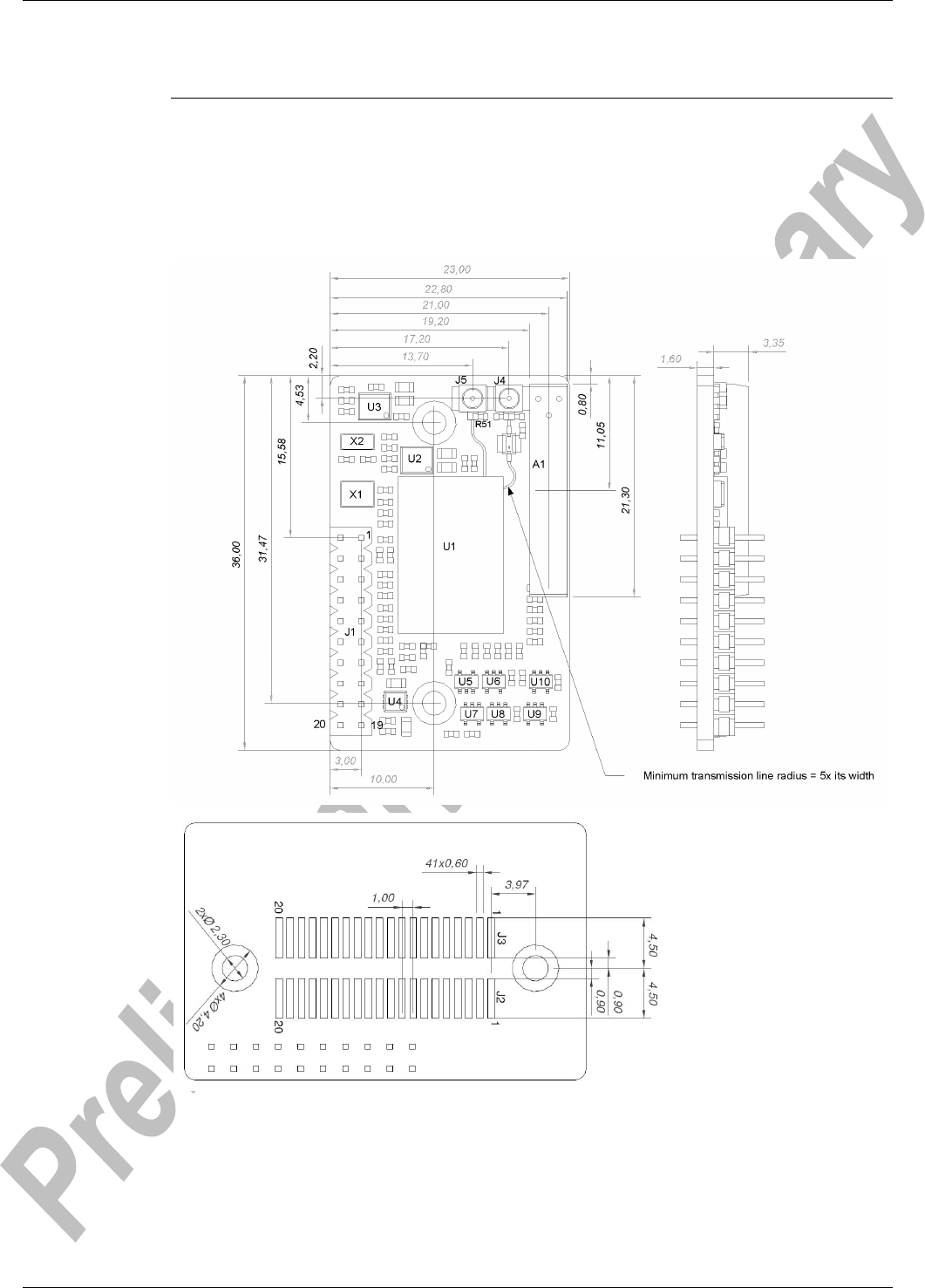
4.1 Board Outlines
4.1.1 cB-0904
Figure 5: cB-0904 dimensions [mm].

Version 0.94 - 2006-09 25
4.2 Using the J2/J3 Board-to-Board Connectors
The board-to-board connector should be a 1mm pitch one-piece part connector. The rec-
ommended manufacture is Samtec with many connector options available; see section
4.2.1.1.
Chapter 2 contains more information about the connector and the electrical interface.
4.2.1 Suitable One-Piece Part Connectors
4.2.1.1 Double row ASP-118580-01 / ASP-118581-01 Connectors
This connector is a double row connector and connects both J2 and J3.
This connector has a height of 3.0mm and this has to be considered if components are to be
mounted on the motherboard under the CB-OWLAN211b board. The connector is also avail-
able with a height of 6.0mm and 10.0mm (The FSI-120 series from Samtec).
There are alignment pins on the bottom side of the connector.
The connector is available with M2 threaded inserts ASP-118580-01) that fit the mounting
holes on the board. You may screw the CB-OWLAN211b board directly into these inserts. If
you want to have a tighter and more secure mounting you may use longer screws and se-
cure it using a nut on the backside of the motherboard.
Another way to mount the module is to use press-fit nuts on the motherboard and skip the
M2 threads on the connector (ASP-118581-01), see section 4.3 for more information about
press-fit nuts.
Table 11: Double row connectors from Samtec.
Samtec order
number
Quote
number
Equivalent part Package Remark
REF-120021-01 55392 FSI-120-03-G-D-AB Tube Align pin on bottom
side only
REF-120021-02 55392 FSI-120-03-G-D-AB-K-TR Tape-n-Reel Align pin on bottom
side only
REF-120018-01 55392 FSI-120-03-G-D-M-AB Tube With M2 threaded
inserts and align pin
on bottom side only
REF-120018-02 55392 FSI-120-03-G-D-M-AB-K-TR
Tape-n-Reel With M2 threaded
inserts and align pin
on bottom side only
NOTE:
When ordering connectors from Samtec or an official Samtec distributor, please use the REF
order number and refer to the connectBlue global quote number for best price. For technical
questions regarding the Samtec connectors please contact connectBlue or Samtec at
(Scandinavia@samtec.com).
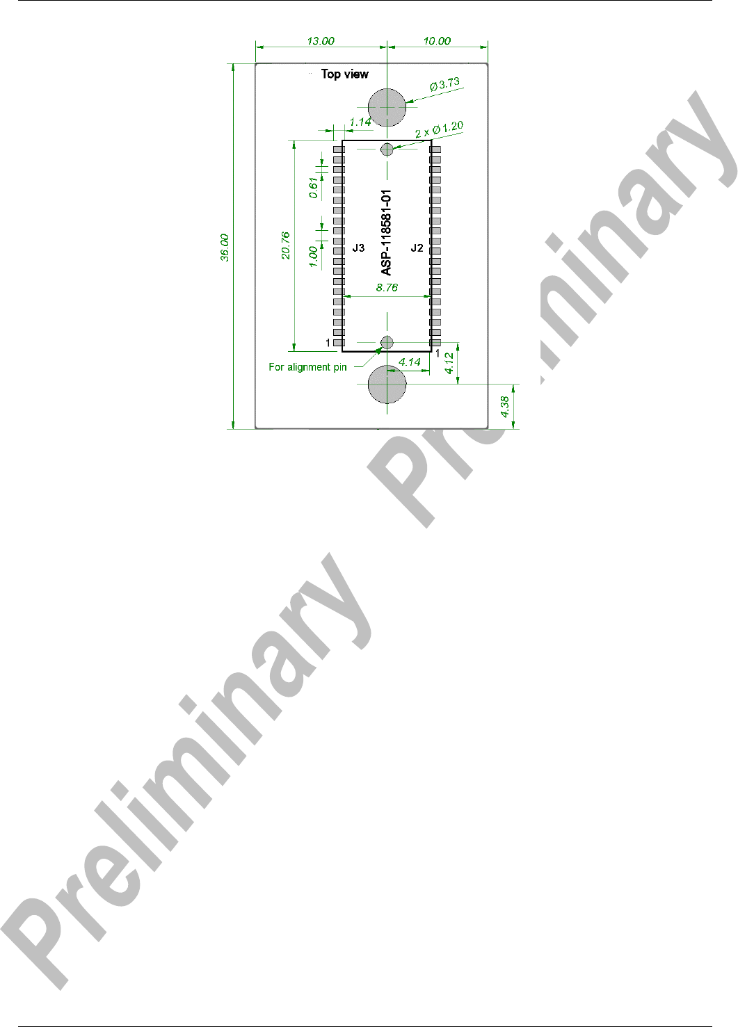
See Figure 6 for more information about the connector and necessary measurements on the
motherboard. The large mounting holes on the motherboard are designed for press-fit nuts
and could be smaller if press-fit nuts are not used.
Version 0.94 - 2006-09 26
Figure 6: Host PCB layout [mm] for double row connector.

Version 0.94 - 2006-09 27
4.3 Using Press-Fit Nuts for Mounting the Module
A press-fit nut is pressed into the PCB from the bottom side with a special press tool. M2
sized press-fit nuts are suitable for the modules (see Figure 6) and are manufactured by
PEM Fastening Systems (www.pemnet.com), part no KFS2-M2 (see Figure 7). Be careful
with the distance between the nuts regarding alignment.
Figure 7: KFS2-M2 press-fit nut.
Spacer-pipes are recommended to use between the PCBs when press-fit nuts are used.
4.4 Antenna Issues
The unit cannot be mounted arbitrary, because of the radio communication. The unit with an
internal surface mounted antenna (CB-OWLAN211bi) cannot be mounted in a metal enclo-
sure.
No metal casing or plastics using metal flakes should be used, avoid also metallic based
paint or lacquer. Keep a minimum clearance of 10mm between the antenna and the casing.
Keep 10 mm free space from metal around the antenna.
If a metal enclosure is required, one of the external antenna options has to be used. See
section 3.2 for more information on the antenna options available.

Version 0.94 - 2006-09 28
5 WLAN Information
In the tables below you can find information about WLAN properties.
Table 12: WLAN information CB-OWLAN211b i/x
Parameter Data
Radio Phillips BGW200 (16dBm)
RF output power max 16dBm
Receive sensitive level -85dBm
Receive input level (max) -20dBm
Output frequency 2.402 –2.480 GHz, ISM band.
WiFi Certified

Version 0.94 - 2006-09 29
6 Regulatory Information
6.1 Declaration of Conformity TBD
We, connectBlue AB, of
Norra Vallgatan 64 3V
SE-211 22 Malmö, Sweden
declare under our sole responsibility that our products:
cB-OWLAN211bi (cB-0095, cB-0096),
cB-OWLAN211bx (cB-0097, cB-0098)
to which this declaration relates, conforms to the following product specifications:
R&TTE Directive 1999/5/EC
EN 300 328 V1.6.1 (2004-11)
EMC Directive: 89/336/EEC
EN 301 489-1 V1.4.1 (2002-08)
EN 301 489-17 V1.2.1 (2002-08)
EN 61000-6-2 (2001)
Safety Compliance
EN 60950-1:2001 and/or IEC 60950-1:2001 (1
st
Edition)
EN 60950-1/A11:2004 + Corrigendum:2004
24/09/2005 Malmö, Sweden
Mats Andersson
CTO of connectBlue AB
If a cB-OWLAN211b i/x is used within EU a notification may be necessary to be made to
each of the national authorities responsible for radio spectrum management of the intention
to place radio equipment that uses frequency bands whose use is not harmonized through-
out the EU, on its national market.
More information at: http://europa.eu.int/comm/enterprise/rtte/gener.htm

Version 0.94 - 2006-09 30
6.2 Safety Compliance
In order to fulfill the safety standard EN 60950-1 the unit must be supplied by a limited power
source.
6.3 FCC and IC Compliance
See Table 1 for information about the different product variants.
6.3.1 Compliance for cB-0904-02
6.3.1.1 FCC Statement for cB-0904-04
This device complies with Part 15 of the FCC Rules. Operation is subject to the following two
conditions: (1) this device may not cause harmful interference, and (2) this device must ac-
cept any interference received, including interference that may cause undesired operation.
NOTE: This equipment has been tested and found to comply with the limits for a Class B
digital device, pursuant to Part 15 of the FCC Rules. These limits are designed to provide
reasonable protection against harmful interference in a residential installation. This equip-
ment generates, uses and can radiate radio frequency energy and, if not installed and used
in accordance with the instructions, may cause harmful interference to radio communica-
tions. However, there is no guarantee that interference will not occur in a particular installa-
tion. If this equipment does cause harmful interference to radio or television reception, which
can be determined by turning the equipment off and on, the user is encouraged to try to cor-
rect the interference by one or more of the following measures:
• Reorient or relocate the receiving antenna
• Increase the separation between the equipment and receiver
• Connect the equipment into an outlet on a circuit different from that to which the re-
ceiver is connected
Consult the dealer or an experienced radio/TV technician for help
6.3.1.1.1 Antenna
Our module type cB-0904-02 is for OEM integrations only. The end-user product will be pro-
fessionally installed in such a manner that only the authorized antennas are used.
6.3.1.1.2 Caution
Any changes or modifications NOT explicitly APPROVED by connectBlue AB could cause
the module to cease to comply with FCC rules part 15, and thus void the user’s authority to
operate the equipment.

Version 0.94 - 2006-09 31
6.3.1.2 IC Compliance
Operation is subject to the following two conditions:
(1) this device may not cause harmful interference, and
(2) this device must accept any interference received,
including interference that may cause undesired operation.
This device has been designed to operate with an antenna having a maximum gain of 9dBi.
Having a higher gain is strictly prohibited per regulations of Industry Canada. The required
antenna impedance is 50 ohms.
To reduce potential radio interference to other users, the antenna type and its gain should be
so chosen that the equivalent isotropically radiated power (EIRP) is not more than that re-
quired for successful communication.
The installer of this radio equipment must ensure that the antenna is located or pointed such
that it does not emit RF field in excess of Health Canada limits for the general population;
consult Safety Code 6, obtainable from Health Canada’s website www.hc-sc.gc.ca/rpb.
6.3.1.3 Labeling Requirements for End Product
For an end product using the product cB-0904-02 there must be a label containing, at least,
the following information:
The label must be affixed on an exterior surface of the end product such that it will be visible
upon inspection in compliance with the modular approval guidelines developed by the FCC.
Where the module will be installed in final products larger than 8 cm x 10 cm following
statement has to be placed ONTO the device.
“This device complies with Part 15 of the FCC Rules.
Operation is subject to the following two conditions:
(1) this device may not cause harmful interference, and
(2) this device must accept any interference received, including interference that may cause
undesired operation.”
In case, where the final product will be installed in locations where the end-consumer is not
able to see the FCC ID and/or this statement, the FCC ID and the statement shall also be in-
cluded in the end-product manual.
6.3.1.4 RF-exposure Statement for cB-0904-02
This modular transmitter MUST have a separation distance of at least 2.5 cm between the
antenna and the body of the user or nearby persons, excluding hands, wrists, feet, and an-
kles.
If the radio module is installed in a laptop display, transmission MUST be prevented if the lid
is closed to ensure that the minimum distance of 2.5 cm between the user and the transmit-
ting antenna is maintained.
Any notification to the end user of installation or removal instructions about the integrated ra-
dio module is NOT allowed.
This device contains
FCC ID: PVH090402
IC: 5325A-090402
Version 0.94 - 2006-09 32
6.4 UL listing information
If a customer intends to UL list a product including any of the Bluetooth modules based on
the PCB cB-0904-02 this information is useful:
The printed circuit board if produced according to the following specification:
• UL recognized ZPMV2 min. 105 °C flame class V-0 or better.
6.5 Compliance with RoHS directive
All products based on the PCB cB-0904-02 are produced according to the RoHS (Restriction
of the use of certain Hazardous Substances in electrical and electronic equipment) directive
and complies with the directive.

Version 0.94 - 2006-09 33
7 Guidelines for Efficient and Safe Use
7.1 General
Read this information before using your OWLAN211b module.
For any exceptions, due to national requirements or limitations, when using your
OWLAN211b module, please contact connectBlue AB.
Note: Changes or modifications to the product not expressly approved by
connectBlue AB will void the user’s authority to operate the equipment.
7.2 Product Care
• Do not expose your product to liquid or moisture.
• Do not expose you product to extreme hot or cold temperature (see Section 2.3.3 for
further information)
• Do not expose your product to lit candles, cigarettes, cigars, open flames, etc.
• Do not drop, throw or try to bend your product since rough treatment could damage your
product.
• Do not attempt to disassemble your product. Doing so will void warranty. The product
does not contain consumer serviceable or replaceable components. Service should only
be performed by connectBlue AB.
• Do not paint your product as the paint could prevent normal use.
• If you will not be using your product for a while, store it in a place that is dry, free from
damp, dust and extreme heat and cold.
7.3 Radio Frequency Exposure
The OWLAN211b module contains a small radio transmitter and receiver. During
communication with other WLAN products the OWLAN211b Module receives and transmits
radio frequency (RF) electromagnetic fields (microwaves) in the frequency range 2400 to
2500 MHz. The output power of the radio transmitter is very low.
When using the OWLAN211b module, you will be exposed to some of the transmitted RF
energy. This exposure is well below the prescribed limits in all national and international RF
safety standards and regulations.

Version 0.94 - 2006-09 34
7.4 Electronic Equipment
Most modern electronic equipment, for example, in hospitals and cars, is shielded from RF
energy. However, certain electronic equipment is not. Therefore:
Note: This equipment emits RF energy in the ISM (Industrial, Scientific, Medical) band.
Please insure that all medical devices used in proximity to this device meet appropriate
susceptibility specifications for this type of RF energy.
7.5 Potentially Explosive Atmospheres
Turn off your electronic device before entering an area with potentially explosive
atmosphere. It is rare, but your electronic device could generate sparks. Sparks in such
areas could cause an explosion or fire resulting in bodily injury or even death.
Areas with a potentially explosive atmosphere are often, but not always, clearly marked.
They include fuelling areas, such as petrol station, below deck on boats, fuel or chemical
transfer or storage facilities, and areas where the air contains chemicals or particles, such as
grain, dust, or metal powders.
7.6 Power Supply
The OWLAN211b module must be supplied by a limited power source according to
EN 60950-1.
• Connect your power supply only to designated power-sources as marked on the product.
• Make sure all cords and cable are positioned so that they will not be stepped on, tripped
over or otherwise subject to damage or stress.
• To reduce risk of electric shock, unplug the unit from any power source before attempting
to clean it.

Version 0.94 - 2006-09 35
Appendix A - Application Notes
Usually only a subset of the available functionality is of interest to the designer. In addition,
depending on the host system, the electrical interface can be designed in many ways. The
designer can use the step-by-
step guide in this chapter as an aid in the design process.
A.1 Step-by-Step Guide
Table 13: Step-by-step guide with Yes and No answers.
Question Yes No
Are you going to integrate the CB-
OWLAN211b module in a metal
enclosure?
The internal antenna models
cannot be used. Use the OWLAN
211bx.
You are free to choose
between the products. The
internal antenna models
are lower cost and are
easier to design-in. How-
ever, an external antenna
could give better range.
Do you wish to use SPI when com-
municating with the CB-OWLAN211b
Module?
TBD TBD
TBD TBD
Are you using a 5V host system? The SPI interface is 5V tolerant TBD
Is low power consumption important?
The CB-OWLAN211b Module can
be held in RESET mode to en-
able maximum power saving.
Do you want to manually reset the
module?
Version 0.94 - 2006-09 36
A.2 Design Examples
A.2.1 Basic Design
Basic desing example.
Note: The 10uF decoupling capacitor must be positioned close to the module power supply
pins. This to compensate for the current peaks during power up and reset release.
Figure 8: Basic design example.
CB-0904 CPU / MPU
SPI-SS-n
SPI-MOSI
SPI-MISO
SPI-CLK
SPI-ExInt
SPI
Interrupt
GPIO *RESET
10µF
+3.3V
Version 0.94 - 2006-09 37
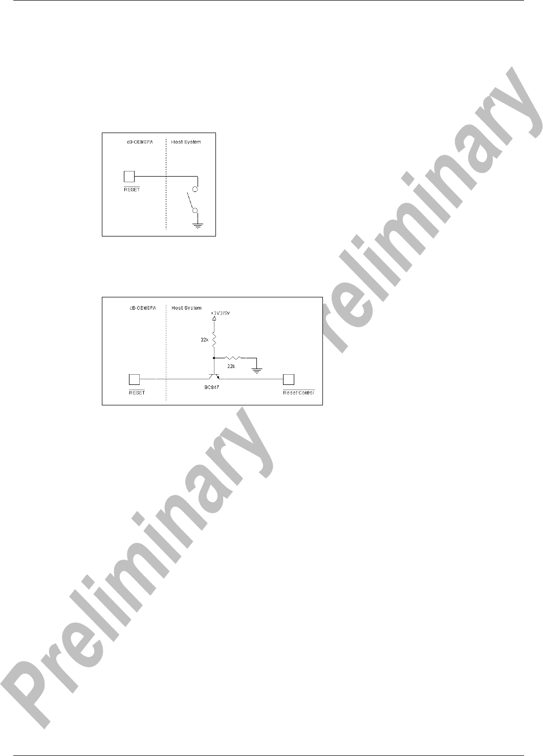
A.2.2 Reset
The
RESET
pin can be connected to an external reset source, see Figure 9 for a switch ex-
ample.
If the reset signal is connected to an output signal it must be an open drain or collector, see
Figure 10.
Figure 9: A reset switch.
The
RESET
pin can be left unconnected if not used.
Figure 10: Design of an open collector reset from an active high output.
A.2.3 Bluetooth co-existence
TBD
Version 0.94 - 2006-09 38
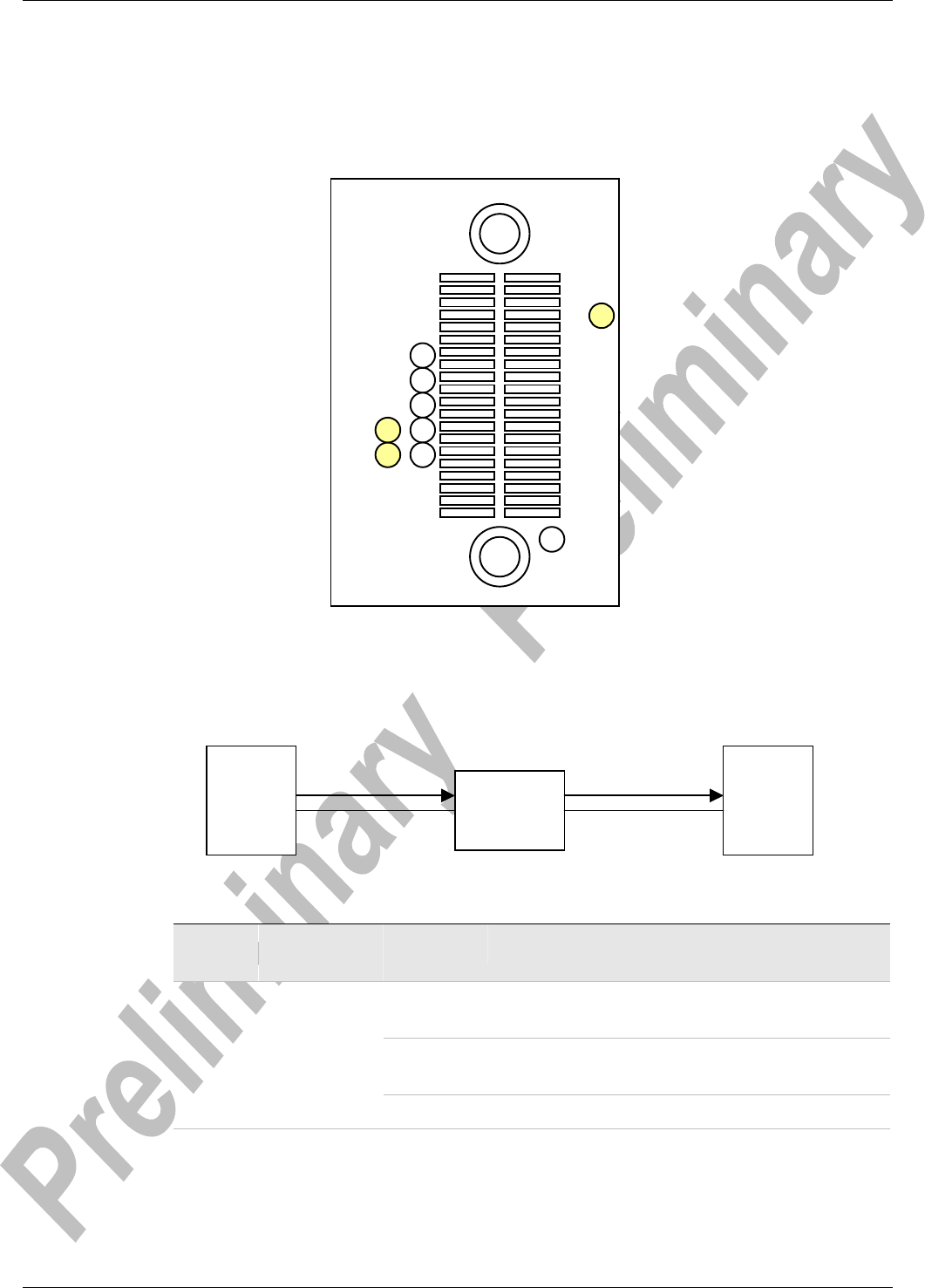
A.3 Test Points
The firmware outputs diagnostic messages during runtime to aid driver development and for
easier troubleshooting. The messages are output as serial data, TTL-level, at test point 4.
See Figure 11 for localization of test points.
Figure 11: Bottom View showing the location of test points.
A RS232 level shifter needs to be used if the diagnostic messages shall be logged using a
PC.
Table 14: Test Points
Symbol Parameter Signal
Level
Type Description
TP1 REFCLK_OUT CMOS O Clock reference output.
Basic variance: 44.000000MHz ± 10ppm
TP4 TX CMOS O Diagnostic Messages @ 38400 baud, 8-data
bits, even parity, 1 stop-bit
TP5 RX CMOS I Do not connect.
A.3.1 Examples
The following are examples of diagnostic output from the device.
CB-0904
TTL → RS232
Level shifter
PC
TP4 COM1: RX
COM1:
GND
GND: e.g J1-1
TP4
TP5
TP1
Version 0.94 - 2006-09 39
NOTE: The output format is not fixed and can therefore change without notice be-
tween different versions of the firmware. The examples listed below are shown for an
education purpose only.
A.3.1.1 After Firmware Download
After firmware download is completed the following output is given:
The most important information, besides the fact that the firmware is actually loaded and run-
ning, are the version number and the MAC address. The example above lists firmware
version 6.35 and a MAC address of 00:12:F3:FF:FF:FD
A.3.1.2 Scan
Scan commands are, similar to other commands, prefixed with a ‘>’ to indicate start of com-
mand, and a ‘<’ to indicate end of command.
A.3.1.3 WEP Keys
The message above shows a successful installation of a WEP key.
Copyright 2005 Philips Semiconductors Inc.
WLAN SOFTWARE BUILD VERSION 6.35.11.17.05
Nov 17 2005, 13:07:39
BUILD FOR RELEASE, 0th time run...
Me Bl
0:12:F3:FF:FF:FD
LA 1
>Sc
<sc
Pairwise WEP key installed

Version 0.94 - 2006-09 40
A.3.1.4 Association
The example above shows a successful association with an access point named “cb-test3”.
The following sequence can be read:
1. A scan is issued to find the access point. (Sc)
2. A join confirm is received. (J-Cfm)
3. An association request is made. (As-Req)
4. An association response is received. (As-Res)
5. Association complete and successful. (A)
Me Bl
***cb-test3
>MESc
>Sc
<sc
<MeSc
J-Cfm
As-Req
As-Res
CW value15
TXOP: 0
CW value15
TXOP: 0
CW value7
TXOP: 94
CW value3
TXOP: 47
A