u blox Malmo 0941 Wireless Communication System Module User Manual Electrical and Mechanical Datasheet
u-blox Malmo AB Wireless Communication System Module Electrical and Mechanical Datasheet
Contents
- 1. Electrical and Mechanical Datasheet
- 2. Electrical and Mechaniocal Datasheet
- 3. Users Manual
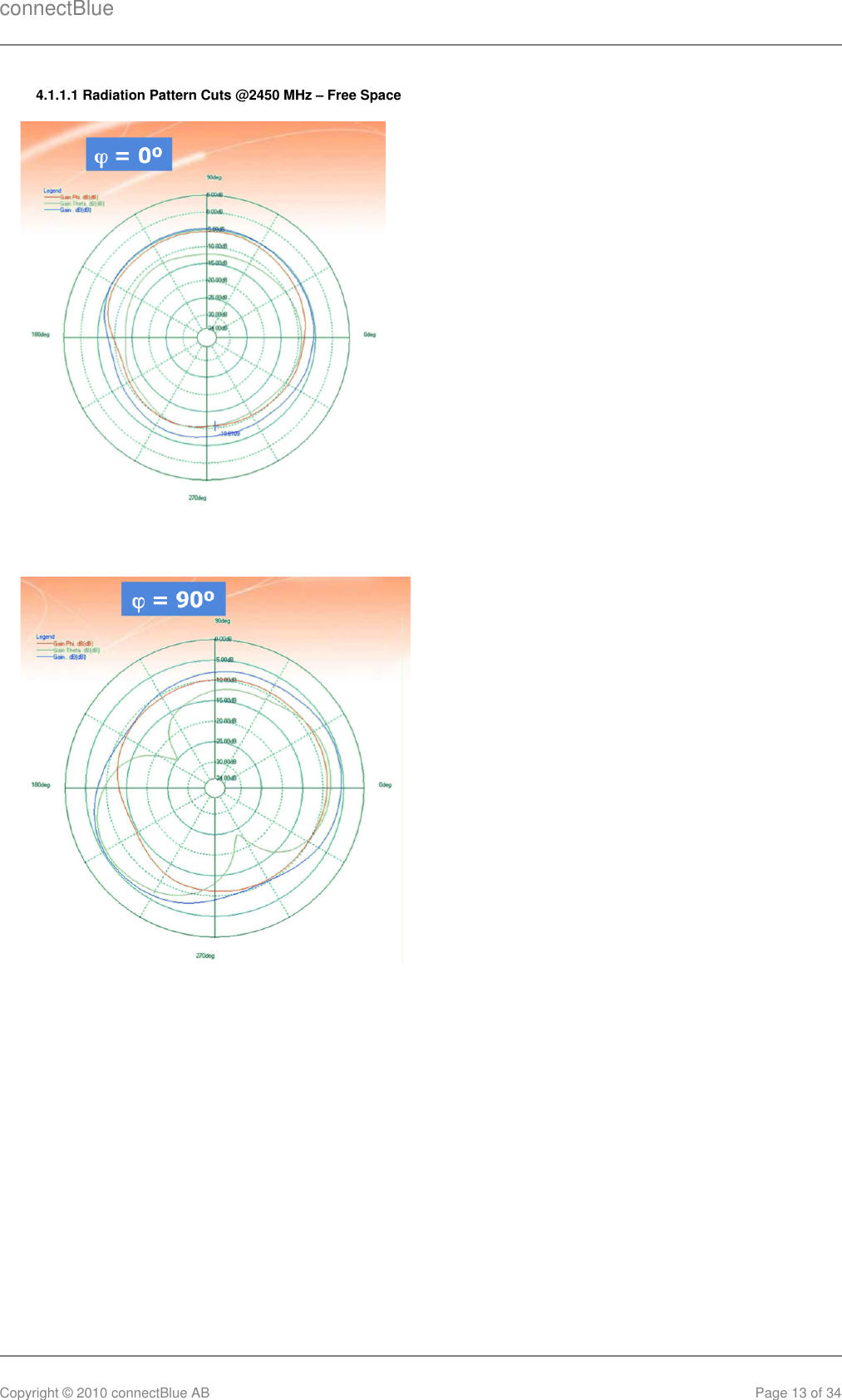
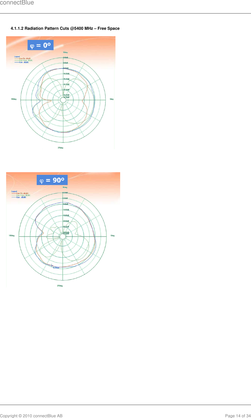
- 4. Antenna Guide
- 5. User Manual
Electrical and Mechanical Datasheet