u blox 09 BMD-330 User Manual BMD 330 Datasheet
Rigado, Inc. BMD-330 BMD 330 Datasheet
UserManual.wiki
>
u blox
>
09 User Manual
User Manual
Navigation menu
Upload a User Manual
Namespaces
Wiki Guide
HTML
PDF
Info
Views
User Manual
Discussion / Help
Navigation
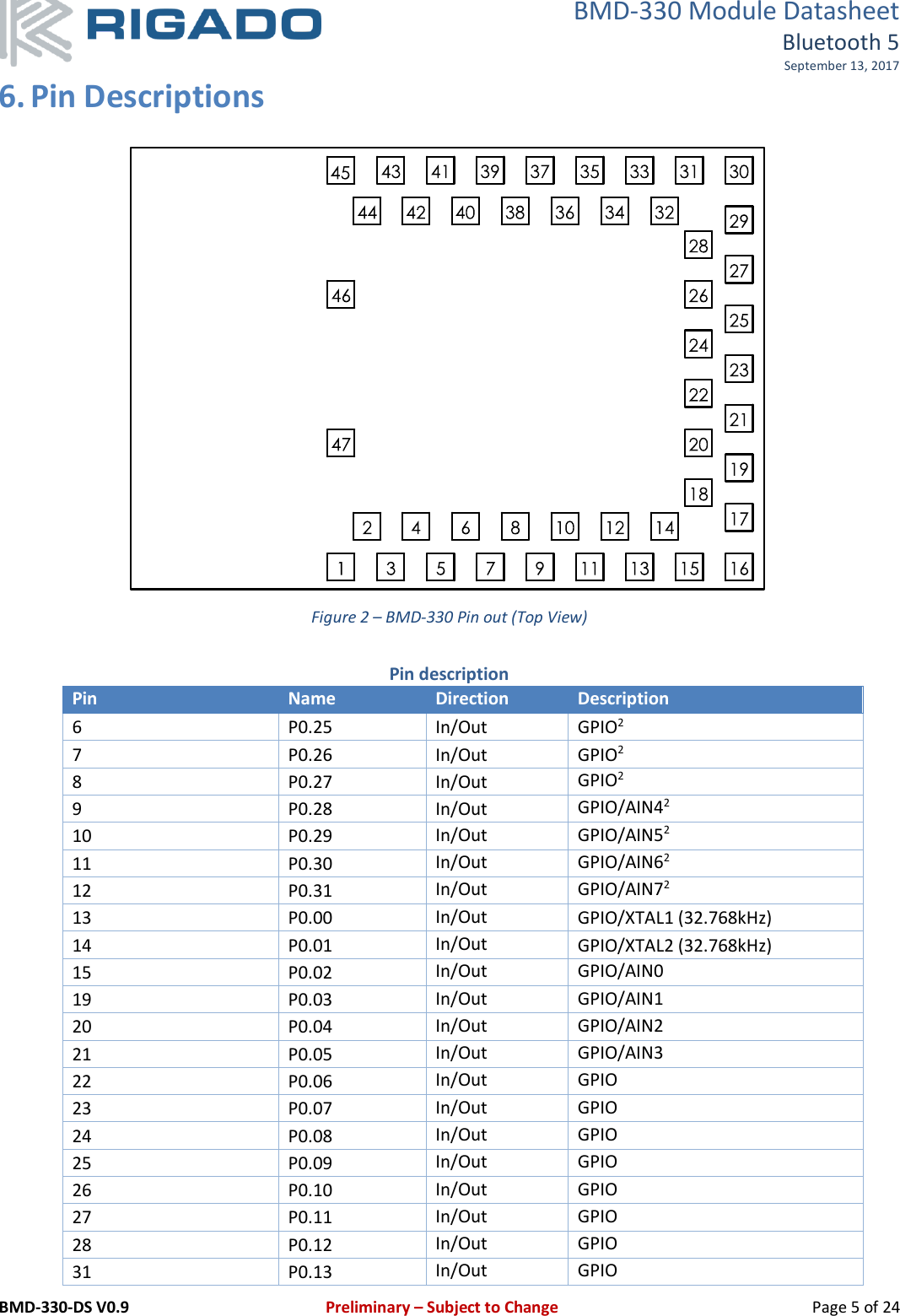
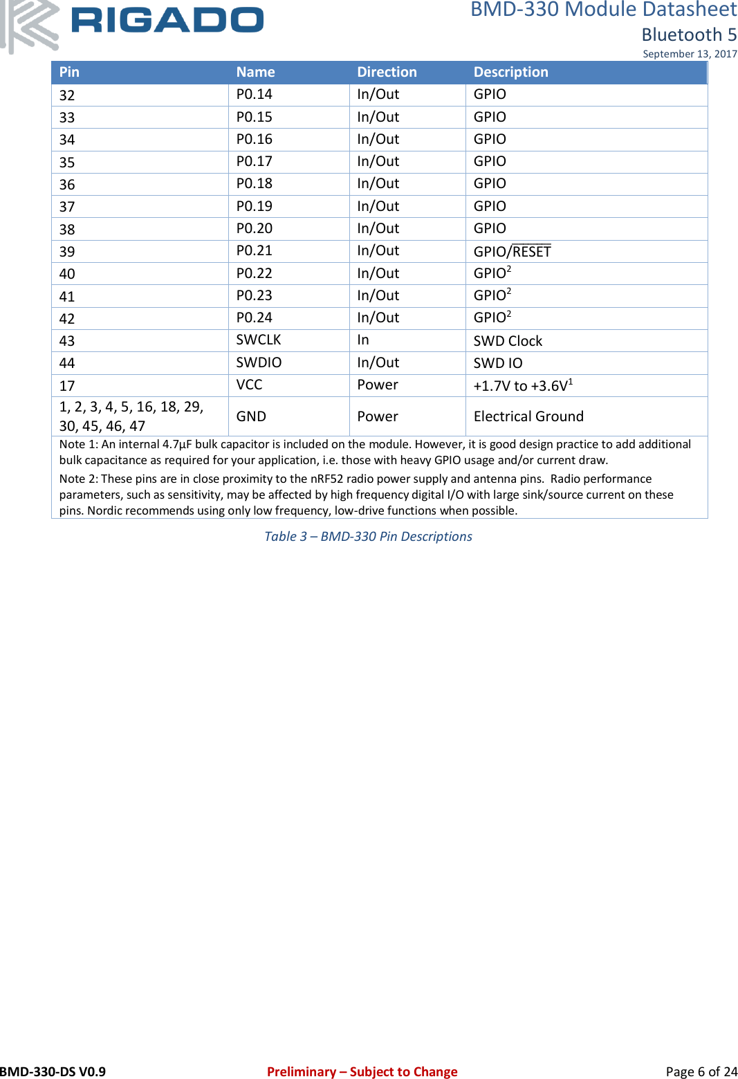
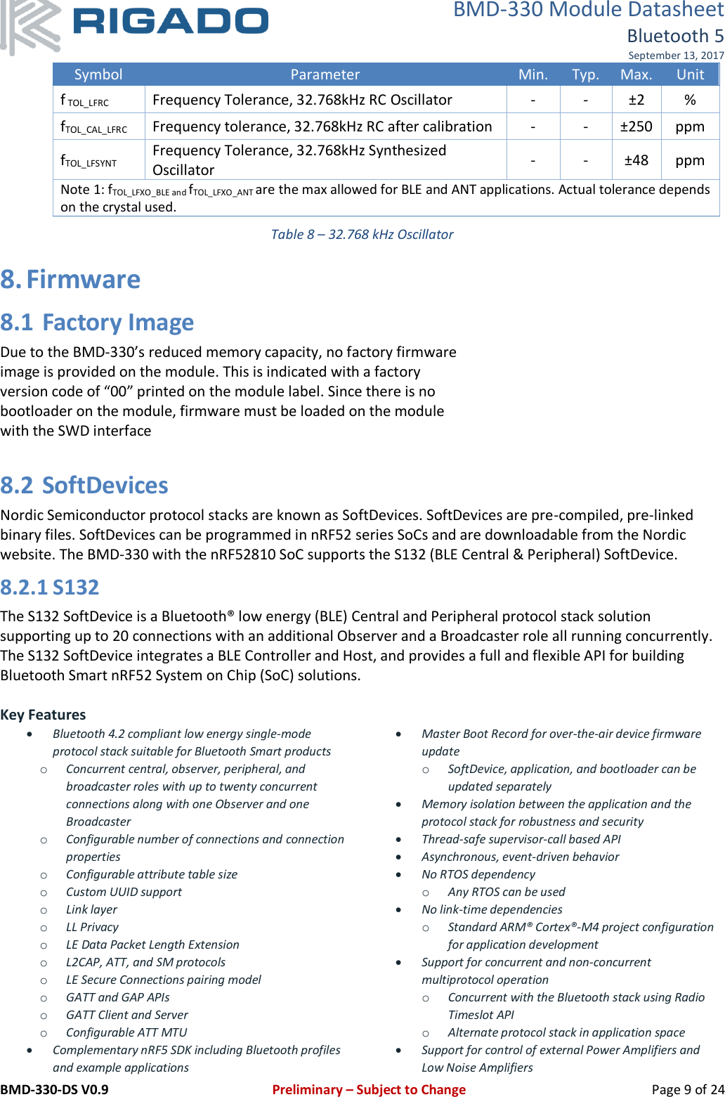
![BMD-330 Module Datasheet Bluetooth 5 September 13, 2017 BMD-330-DS V0.9 Preliminary – Subject to Change Page 8 of 24 7.4 Module RESET GPIO pin P0.21 may be used for a hardware reset. In order to utilize P0.21 as a hardware reset, the UICR registers PSELRESET[0] and PSELRESET[1] must be set alike, to the value of 0x7FFFFF15. When P0.21 is programmed as RESET̅̅̅̅̅̅̅̅, the internal pull-up is automatically enabled. Rigado and Nordic example applications and development kits program P0.21 as RESET̅̅̅̅̅̅̅̅. 7.5 Debug & Programming The BMD-330 supports the two pin Serial Wire Debug (SWD) interface and offers flexible and powerful mechanism for non-intrusive debugging of program code. Breakpoints, single stepping, and instruction trace capture of code execution flow are part of this support. 7.6 Clocks The BMD-330 requires two clocks, a high frequency clock and a low frequency clock. The high frequency clock is provided on-module by a high-accuracy 32-MHz crystal as required by the nRF52810 for radio operation. The low frequency clock can be provided internally by an RC oscillator or synthesized from the fast clock; or externally by a 32.768 kHz crystal. An external crystal provides the lowest power consumption and greatest accuracy. Using the internal RC oscillator with calibration provides acceptable performance for BLE applications at a reduced cost and slight increase in power consumption. Note: the ANT protocol requires the use of an external crystal. 32.768 kHz Crystal (LFXO) Symbol Parameter Typ. Max. Unit FNOM_LFXO Crystal frequency 32.768 - kHz FTOL_LFXO_BLE Frequency tolerance, BLE applications - ±250 ppm CL_LFXO Load Capacitance - 12.5 pF C0_LFXO Shunt Capacitance - 2 pF RS_LFXO Equivalent series resistance - 100 kΩ Cpin Input Capacitance on XL1 & XL2 pads 4 - pF Table 7 – 32.768 kHz Crystal 32.768 kHz Oscillator Comparison Symbol Parameter Min. Typ. Max. Unit ILFXO Current for 32.768kHz Crystal Oscillator - 0.25 - µA ILFRC Current for 32.768kHz RC Oscillator - 0.6 1 µA ILFSYNT Current for 32.768kHz Synthesized Oscillator - 100 - µA fTOL_LFXO_BLE Frequency Tolerance, 32.768kHz Crystal Oscillator (BLE Stack)1 - - ±250 ppm fTOL_LFXO_ANT Frequency Tolerance, 32.768kHz Crystal Oscillator (ANT Stack)1 - - ±50 ppm](https://usermanual.wiki/u-blox/09/User-Guide-3622104-Page-8.png)
![BMD-330 Module Datasheet Bluetooth 5 September 13, 2017 BMD-330-DS V0.9 Preliminary – Subject to Change Page 10 of 24 8.3 MAC Address Info The BMD-330 module comes preprogrammed with a unique MAC address from the factory. The MAC address is also printed on a 2D barcode on the top of the module. Figure 3 – BMD-300/301 MAC Address on Label The 6-byte BLE Radio MAC address is stored in the nRF52810 UICR at NRF_UICR_BASE+0x80 LSB first. From the factory, the MAC address can be read over SWD since read-back protection is not enabled. If performing a full-chip-erase, the MAC can then only be recovered from the 2D barcode and human-readable text. UICR Register: NRF_UICR + 0x80 (0x10001080): MAC_Addr [0] (0xZZ) NRF_UICR + 0x81 (0x10001081): MAC_Addr [1] (0xYY) NRF_UICR + 0x82 (0x10001082): MAC_Addr [2] (0xXX) NRF_UICR + 0x83 (0x10001083): MAC_Addr [3] (0x93) NRF_UICR + 0x84 (0x10001084): MAC_Addr [4] (0x54) NRF_UICR + 0x85 (0x10001085): MAC_Addr [5] (0x94)](https://usermanual.wiki/u-blox/09/User-Guide-3622104-Page-10.png)