u blox JODYW164 WLAN/Bluetooth host-based multiradio module JODY-W1 User Manual JODY W1 series
u-blox AG WLAN/Bluetooth host-based multiradio module JODY-W1 JODY W1 series
u blox >
Contents
- 1. Data Sheet
- 2. Antenna Reference Design Guide
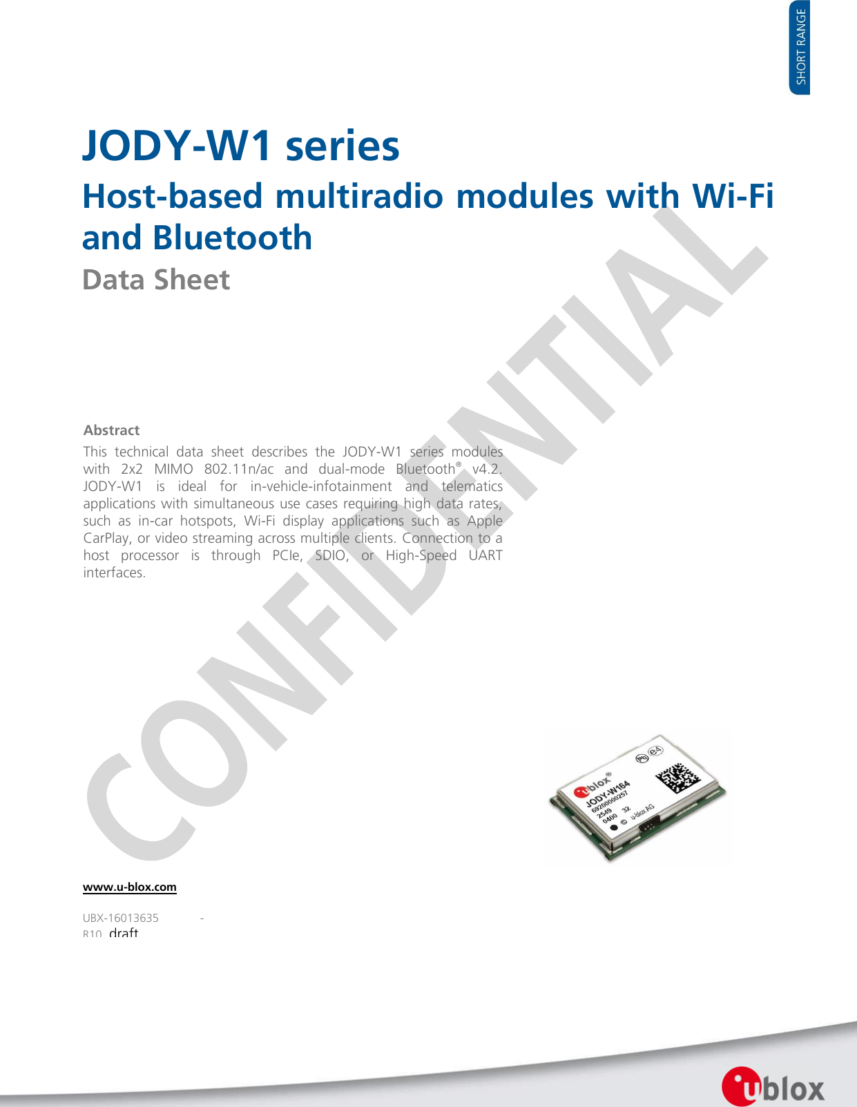
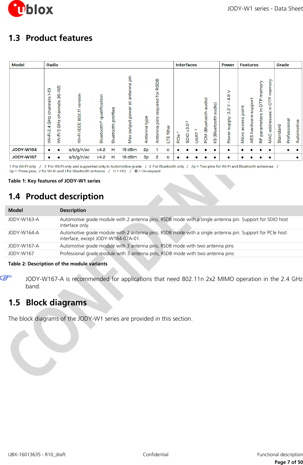
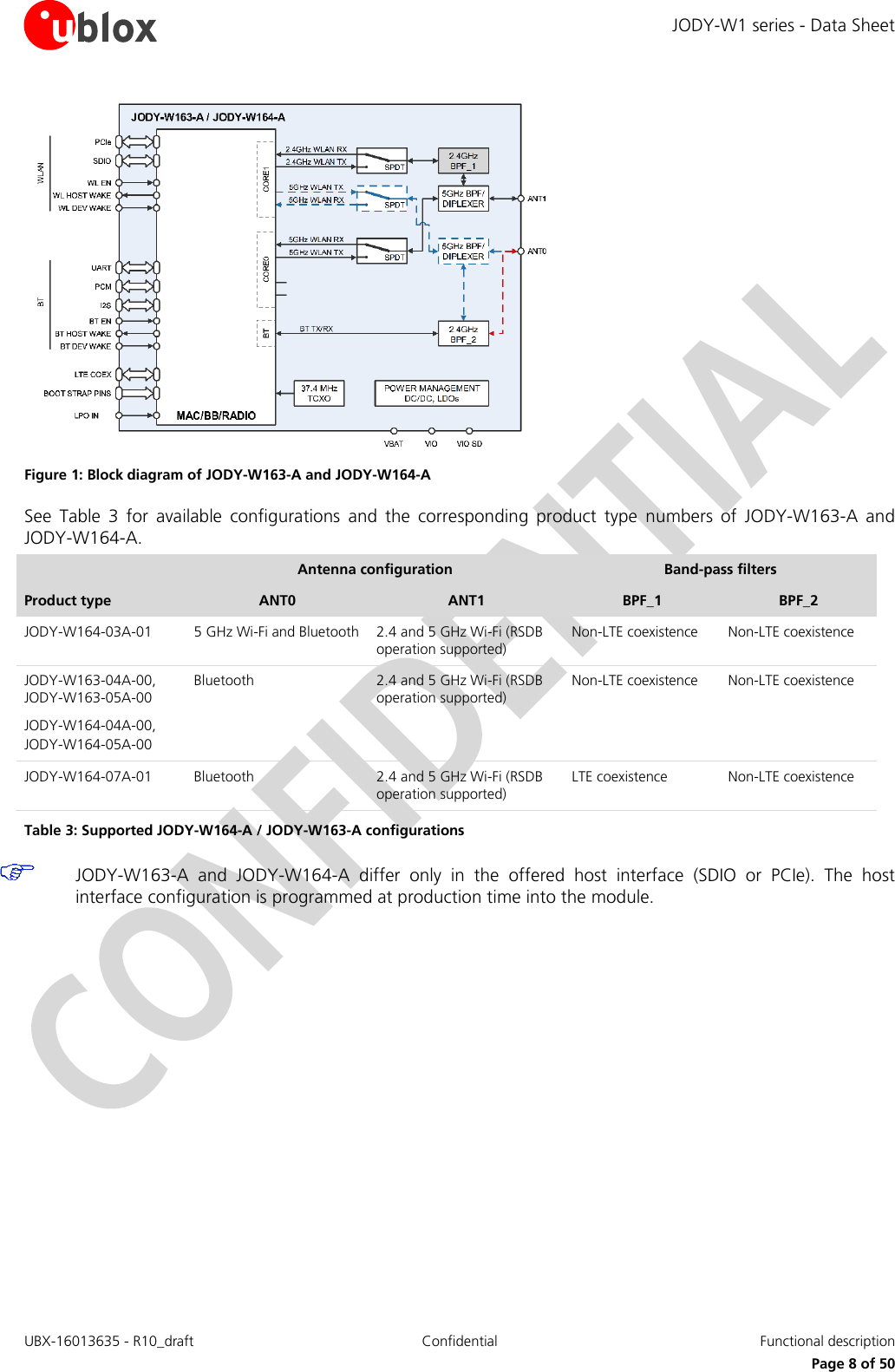
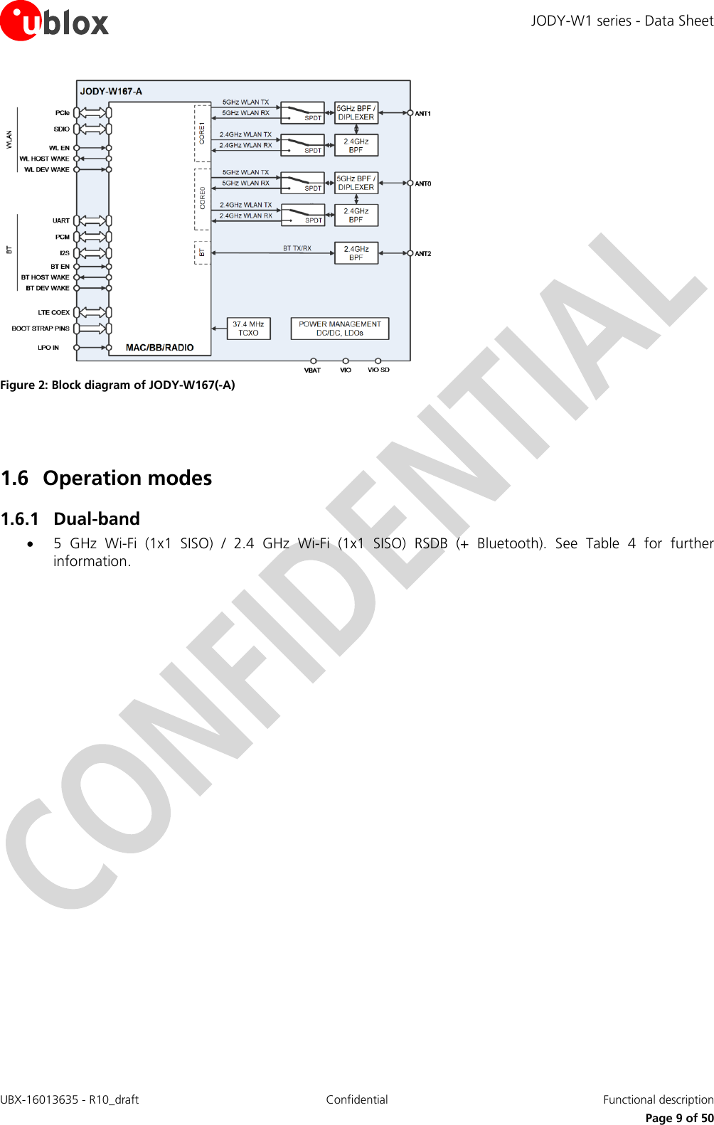
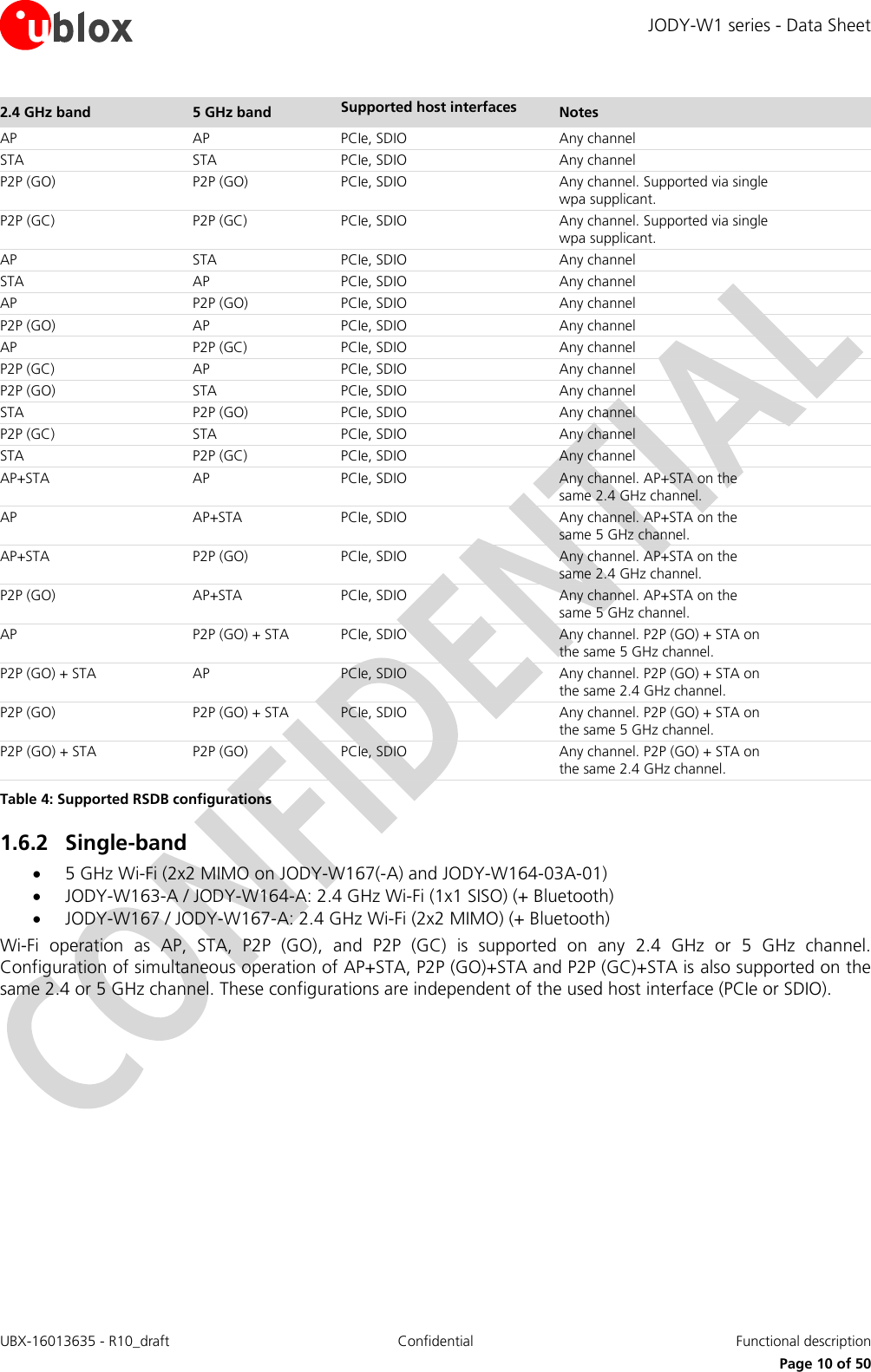
Data Sheet
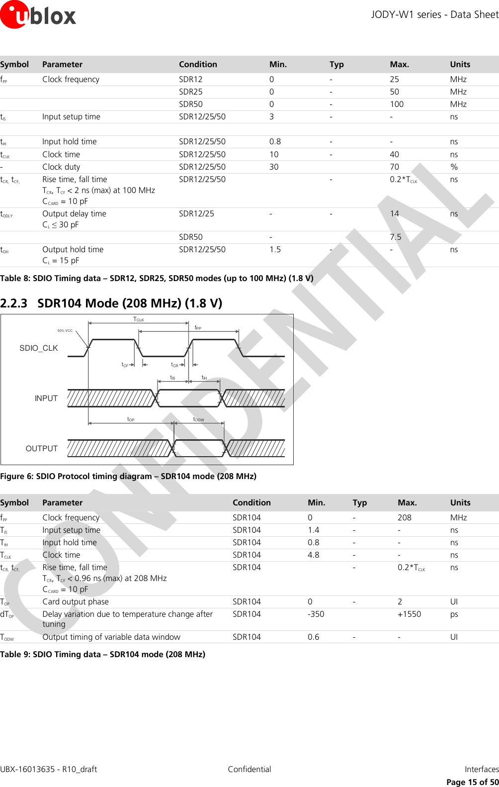
![JODY-W1 series - Data Sheet UBX-16013635 - R10_draft Confidential Interfaces Page 16 of 50 2.2.4 DDR50 Mode (50 MHz) (1.8 V) Figure 7: SDIO CMD Timing diagram – DDR50 mode (50 MHz) Figure 8: SDIO DAT[3:0] Timing diagram – DDR50 mode (50 MHz) Symbol Parameter Condition Min. Typ Max. Units Clock TCLK Clock time 50 MHz (max) between rising edges DDR50 20 - - ns tCR, tCF, Rise time, fall time TCR, TCF < 4.00 ns (max) at 50 MHz CCARD = 10 pF DDR50 - - 0.2*TCLK ns Clock Duty DDR50 45 - 55 % CMD Input (referenced to clock rising edge) tIS Input setup time CCARD ≤ 10 pF (1 card) DDR50 6 - - ns tIH Input hold time CCARD ≤ 10 pF (1 card) DDR50 0.8 - - ns CMD Output (referenced to clock rising edge) tODLY Output delay time during data transfer mode CL ≤ 30 pF (1 card) DDR50 - - 13.7 ns tOHLD Output hold time CL ≥ 15 pF (1 card) DDR50 1.5 - - ns DAT[3:0] Input (referenced to clock rising and falling edges) tIS2x Input setup time CCARD ≤ 10 pF (1 card) DDR50 3 ns tIH2x Input hold time CCARD ≤ 10 pF (1 card) DDR50 0.8 ns SDIO_CLKCMD INPUTCMD OUTPUT fPPtCFtCRtODLYtOHLDtIStIH50% VCCTCLKSDIO_CLKDAT INPUTfPPtCFtCRtISU2x50% VCCTCLKDAT OUTPUTtIH2xtISU2xtIH2xtODLY2x(min)tODLY2x(max)tODLY2x(min)tODLY2x(max)](https://usermanual.wiki/u-blox/JODYW164.Data-Sheet/User-Guide-3927160-Page-16.png)
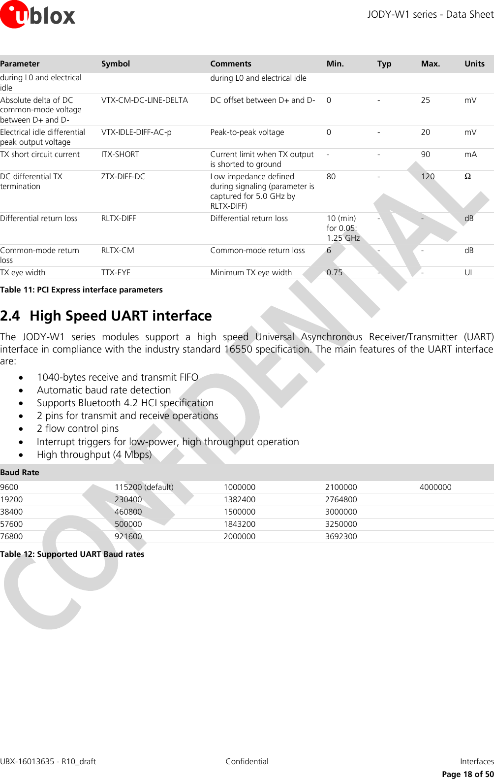
![JODY-W1 series - Data Sheet UBX-16013635 - R10_draft Confidential Interfaces Page 17 of 50 Symbol Parameter Condition Min. Typ Max. Units DAT[3:0] Output (referenced to clock rising and falling edges) tODLY2x (max) Output delay time during data transfer mode CL ≤ 25 pF (1 card) DDR50 7.5 ns tODLY2x (min) Output hold time CL ≥ 15 pF (1 card) DDR50 1.5 ns Table 10: SDIO Timing data – DDR50 mode (50 MHz) 2.3 PCI Express interface The PCI Express interface complies with the PCIe v3.0 standard at Gen1 speed and allows a host controller using the PCIe bus protocol to access the Wi-Fi function of the JODY-W1 series modules. The following table shows the parameters for the PCI Express interface. Parameter Symbol Comments Min. Typ Max. Units General Baud rate BPS - - 5 - Gbaud Reference clock amplitude Vref LVPECL, AC coupled 1 - - V Receiver Differential termination ZRX-DIFF-DC Differential termination 80 100 120 Ω DC impedance ZRX-DC DC common-mode impedance 40 50 60 Ω Power down termination (POS) ZRX-HIGH-IMP-DC-POS Power-down or RESET high impedance 100k - - Ω Power down termination (NEG) ZRX-HIGH-IMP-DC-NEG Power-down or RESET high impedance 1k - - Ω Input voltage VRX-DIFFp-p AC coupled, differential p-p 175 - - mV Jitter tolerance TRX-EYE Minimum receiver eye width 0.4 - - UI Differential return loss RLRX-DIFF Differential return loss 10 - - dB Common-mode return loss RLRX-CM Common-mode return loss 6 - - dB Unexpected electrical idle enter detect threshold integration time TRX-IDEL-DET-DIFF-ENTERTIME An unexpected electrical idle must be recognized no longer than this time to signal an unexpected idle condition - - 10 ms Signal detect threshold VRX-IDLE-DET-DIFFp-p Electrical idle detect threshold 65 - 175 mV Transmitter Output voltage VTX-DIFFp-p Differential p-p, programmable in 16 steps 0.8 - 1200 mV Output voltage rise time VTX-RISE 20% to 80% 0.125 (2.5 GT/s) 0.15 (5 GT/s) - - - - UI Output voltage fall time VTX-FALL 80% to 20% 0.125 (2.5 GT/s) 0.15 (5 GT/s) - - - - UI RX detection voltage swing VTX-RCV-DETECT The amount of voltage change allowed during receiver detection - - 600 mV TX AC peak common-mode voltage (5 GT/s) VTX-CM-AC-PP TX AC common mode voltage (2.5 GT/s) - - 100 mV TX AC peak common-mode voltage (2.5 GT/s) VTX-CM-AC-P TX AC common mode voltage (5 GT/s) - - 20 mV Absolute delta of DC common-mode voltage VTX-CM-DC-ACTIVE-IDLE-DELTA Absolute delta of DC common-mode voltage 0 - 100 mV](https://usermanual.wiki/u-blox/JODYW164.Data-Sheet/User-Guide-3927160-Page-17.png)
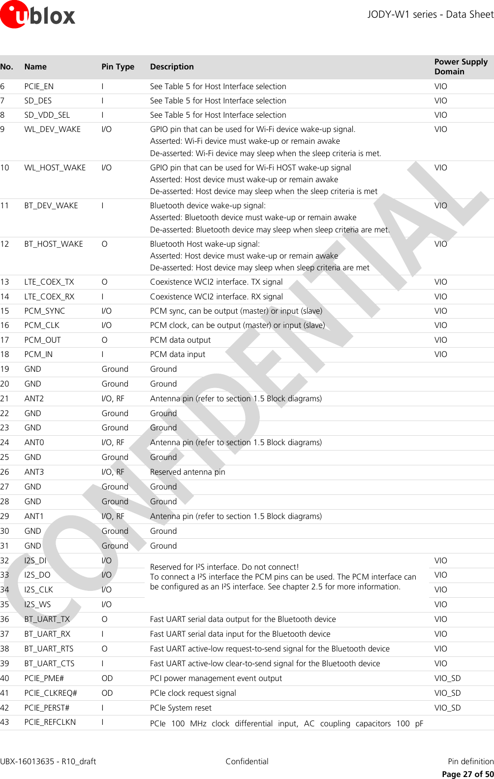
![JODY-W1 series - Data Sheet UBX-16013635 - R10_draft Confidential Pin definition Page 28 of 50 No. Name Pin Type Description Power Supply Domain 44 PCIE_REFCLKP I included in the module. 45 PCIE_RDN I PCIe receiver differential input, DC coupled inputs, use 100 nF AC coupling capacitors placed closer to the Host TDN/TDP differential output 46 PCIE_RDP I 47 PCIE_TDN O PCIe transmitter differential output, AC coupling capacitors 100 nF included in the module, connect to the Host RDN/RDP input directly 48 PCIE_TDP O 49 GND Ground Ground 50 SD_D2 I/O SDIO Data line bit [2] VIO_SD 51 SD_D3 I/O SDIO Data line bit [3] VIO_SD 52 SD_CMD I/O SDIO Command line VIO_SD 53 SD_CLK I SDIO Clock input VIO_SD 54 SD_D0 I/O SDIO Data line bit [0] VIO_SD 55 SD_D1 I/O SDIO Data line bit [1] VIO_SD 56 NC - Leave unconnected (internally connected to the USB interface, debugging only) 57 NC - Leave unconnected (internally connected to the USB interface, debugging only) 58 WL_EN I Power up or power down the Wi-Fi section of the chipset (like a reset) VIO 59 BT_EN I Power up or power down the Bluetooth section of the chipset (like a reset) VIO 60 LPO_IN I Clock input for external sleep clock source (32.768 kHz) EP GND Ground 15 Ground/Thermal exposed pins, connect to the ground Table 21: JODY-W1 series pin description](https://usermanual.wiki/u-blox/JODYW164.Data-Sheet/User-Guide-3927160-Page-28.png)
![JODY-W1 series - Data Sheet UBX-16013635 - R10_draft Confidential Host drivers and firmware Page 33 of 50 5 Host drivers and firmware 5.1 General principle The JODY-W1 series module does not contain any persistent software. A firmware binary will be downloaded by the host operating system driver on system start-up. 5.2 Supported operating systems 5.2.1 Linux Linux device drivers are available free of charge from the chipset manufacturer. A Software License Agreement (SLA) must be signed with the chipset manufacturer to obtain the driver package. This package includes: Dedicated Kernel driver, to bind the Wi-Fi device to the kernel. The driver sources will be provided. A dedicated Wi-Fi firmware image, which will be uploaded during initialization of the Wi-Fi device. A dedicated Bluetooth firmware image, which will be uploaded during initialization of the Bluetooth device. Laboratory and manufacturing tools. For a detailed description of the driver packages, refer to JODY-W1 series System Integration Manual [2].](https://usermanual.wiki/u-blox/JODYW164.Data-Sheet/User-Guide-3927160-Page-33.png)
![JODY-W1 series - Data Sheet UBX-16013635 - R10_draft Confidential Mechanical specifications Page 34 of 50 6 Mechanical specifications Figure 19: JODY-W1 series dimensions (bottom view) Parameter Description Typical Tolerance A Module Length [mm] 19.8 (779.5 mil) +0.35/-0.1 (+13.8/-3.9 mil) B Module Width [mm] 13.8 (543.3 mil) +0.1/-0.1 (+3.9/-3.9 mil) C Module Thickness [mm] 2.5 (98.4 mil) +0.2/-0.2 (+7.9/-7.9 mil) ccc Seating Plane Coplanarity [mm] <0.1 (3.94 mil) D PCB Edge to Pin Edge [mm] 0.3 (11.8 mil) +0.20/-0.20 (+7.9/-7.9 mil) E Pin Width [mm] 0.7 (27.6 mil) +0.05/-0.05 (+2.0/-2.0 mil) F Pin Length [mm] 0.95 (37.4 mil) +0.05/-0.05 (+2.0/-2.0 mil) G Pin to Pin Pitch [mm] 1.0 (39.4 mil) +0.02/-0.02 (+0.8/-0.8 mil) H Horizontal Corner Pin to Pin Pitch [mm] 1.125 (44.3 mil) +0.02/-0.02 (+0.8/-0.8 mil) I Lateral Corner Pin to Pin Pitch [mm] 1.125 (44.3 mil) +0.02/-0.02 (+0.8/-0.8 mil) J Horizontal Thermal Pads Pitch [mm] 3.2 (126.0 mil) +0.02/-0.02 (+0.8/-0.8 mil) K Thermal Pad Height [mm] 2.2 (86 6 mil) +0.1/-0.1 (+3.9/-3.9 mil) L Thermal Pad Length [mm] 2.7 (106.3 mil) +0.1/-0.1 (+3.9/-3.9 mil) M Pin 1 Diameter [mm] 0.95 (37.4 mil) +0.05/-0.05 (+2.0/-2.0 mil) N Horizontal Pin to Thermal Pad Pitch [mm] 3.425 (134.8 mil) +0.02/-0.02 (+0.8/-0.8 mil) O Lateral Pin to Thermal Pad Distance [mm] 2.725 (107.3 mil) +0.02/-0.02 (+0.8/-0.8 mil) P Lateral Thermal Pads Pitch [mm] 2.7 (106.3 mil) +0.02/-0.02 (+0.8/-0.8 mil) R Reserved area for future module variants 1.55 (61.0 mil) +0.05/-0.05 (+2.0/-2.0 mil) DEFHDD OGGEDAIBFFLKMJSeatingcccPlaneCHPin1J PNPNOJKeep this area free of copper*Keep this area free of copper*RR*Future module variants can have more pins in this area. To ensure compatibility this area should be kept free of copper.](https://usermanual.wiki/u-blox/JODYW164.Data-Sheet/User-Guide-3927160-Page-34.png)
![JODY-W1 series - Data Sheet UBX-16013635 - R10_draft Confidential Approvals Page 35 of 50 7 Approvals The JODY-W1 series modules comply with the regulatory demands of Federal Communications Commission (FCC), Industry Canada (IC) and the CE mark6. See JODY-W1 series System Integration Manual [2] to obtain information and requirements regarding regulatory compliance of end-products using JODY-W1 series module. Products marked with this lead-free symbol on the product label comply with the "Directive 2002/95/EC of the European Parliament and the Council on the Restriction of Use of certain Hazardous Substances in Electrical and Electronic Equipment" (RoHS). JODY-W1 series Wi-Fi/Bluetooth multi-radio modules are RoHS compliant. No natural rubbers, hygroscopic materials, or materials containing asbestos are employed. All certifications and approvals mentioned below have not been completed yet and are in the final stage currently. 7.1 European Union regulatory compliance The JODY-W1 series module complies with the following regulatory standards: Essential Requirements Radio Equipment Directive 2014/53/EU Standards Safety & Health (Article 3.1a) IEC 60950-1:2005 (2nd Edition) + A1:2009 EN 60950-1:2006 + A11:2009 + A1:2010 + A12:2011 EN 62311:2008 (Wi-Fi) EN 62479:2010 (Bluetooth) EMC (Article 3.1b) EN 301 489-1 V2.1.1 EN 301 489-17 V3.1.1 Radio Spectrum Efficiency (Article 3.2) EN 300 328 V2.1.1 EN 301 893 V2.1.1 EN 300 440 V2.1.1 Essential Requirements RoHS Directive 2011/65/EU Standards Prevention (Article 4.1) EN 50581:2012 7.2 FCC and IC compliance This section contains the FCC and IC compliance information for the JODY-W1 series module. 6 Approvals are pending.](https://usermanual.wiki/u-blox/JODYW164.Data-Sheet/User-Guide-3927160-Page-35.png)
![JODY-W1 series - Data Sheet UBX-16013635 - R10_draft Confidential Approvals Page 38 of 50 This radio transmitter IC: 8595A-JODYW164 / IC: 8595A-JODYW16407A / IC: 8595A-JODYW167 has been approved by ISED to operate with the antenna types listed below with the maximum permissible gain indicated. Antenna types not included in this list, having a gain greater than the maximum gain indicated for that type, are strictly prohibited for use with this device. Le présent émetteur radio IC: 8595A-JODYW164 / IC: 8595A-JODYW16407A / IC: 8595A-JODYW167 a été approuvé par ISED pour fonctionner avec les types d'antenne énumérés ci-dessous et ayant un gain admissible maximal. Les types d'antenne non inclus dans cette liste, et dont le gain est supérieur au gain maximal indiqué, sont strictement interdits pour l'exploitation de l'émetteur. The internal / external antenna(s) used for this module must provide a separation distance of at least 20 cm from all persons and must not be co-located or operating in conjunction with any other antenna or transmitter. See section 7.3 for list of approved antennas. The approval type for all the JODY-W1 series variants is a single modular approval. Due to ISED Modular Approval Requirements (Source: RSP-100 Issue 10), any application which includes the module must be approved by the module manufacturer (u-blox). The application manufacturer must provide design data for the review procedure. 7.3 Certification in other countries Regulatory approvals for using the JODY-W1 series module in Japan, Korea, and Taiwan are pending. 7.4 Approved antennas Please refer to the JODY-W1 antenna reference design [3] for the essential specifications to be fulfilled in the end-product design to make use of the module’s radio type approval. It provides PCB layout details and electrical specifications. The approved antennas that may be connected to the JODY-W1 series module are listed in this section. 7.4.1 Wi-Fi operation For Wi-Fi operation in the 2.4 GHz band and Wi-Fi operation in the 5 GHz band, the JODY-W1 series module has been tested and approved for use with the antennas listed in Table 34. Manufacturer Part Number Antenna type Peak gain [dBi] Validated Regulatory Domain 2.4 GHz band 5 GHz band Any N/A Dipole antenna 2 2 FCC/IC Any N/A Dipole antenna 0 0 ETSI Table 32: List of approved Wi-Fi antennas Important: To be compliant to FCC §15.407(a) the EIRP is not allowed to exceed 125 mW (21 dBm) at any elevation angle above 30 degrees as measured from the horizon when operated as an outdoor access point in U-NII-1 band, 5.150-5.250 GHz. 7.4.2 Bluetooth operation For Bluetooth operation, the JODY-W1 series module has been tested and approved for use with the antennas listed in Table 33. Manufacturer Part Number Antenna type Peak gain [dBi] Validated Regulatory Domain 2.4 GHz band 5 GHz band Any N/A Dipole antenna 2 2 FCC/IC Any N/A Dipole antenna 0 0 ETSI](https://usermanual.wiki/u-blox/JODYW164.Data-Sheet/User-Guide-3927160-Page-38.png)
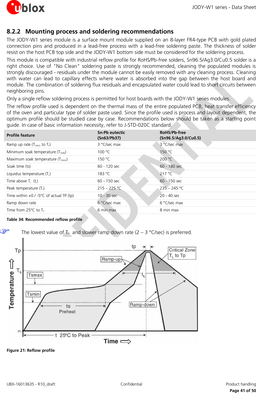
![JODY-W1 series - Data Sheet UBX-16013635 - R10_draft Confidential Product handling Page 40 of 50 8 Product handling 8.1 Packaging The JODY-W1 series modules are delivered as hermetically sealed tape and reels, to enable efficient production, production lot set-up and tear-down. For more information about packaging, see the u-blox Package Information Guide [1]. 8.1.1 Reels The JODY-W1 series modules are deliverable in quantities of 500 pieces on a reel. The JODY-W1 series modules are shipped on reel Type A as described in the u-blox Package Information Guide [1]. 8.1.2 Tapes The dimensions of the tapes are specified in Figure 20. Figure 20: JODY-W1 Tape dimensions 8.2 Shipment, storage and handling For more information regarding shipment, storage and handling see the u-blox Package Information Guide [1]. 8.2.1 Moisture sensitivity levels The JODY-W1 series automotive-grade modules are rated at moisture sensitivity level 3. See moisture sensitive warning label on each shipping bag for detailed information. After opening the dry pack, modules must be mounted within 168 hours in factory conditions of maximum 30 °C/60%RH or must be stored at less than 10%RH. Modules require baking if the humidity indicator card shows more than 10% when read at 23±5°C or if the conditions mentioned above are not met. Please refer to J-STD-033B standard for bake procedure.](https://usermanual.wiki/u-blox/JODYW164.Data-Sheet/User-Guide-3927160-Page-40.png)
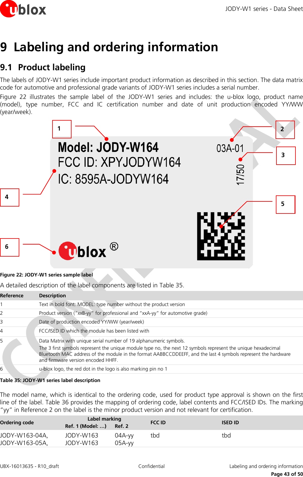
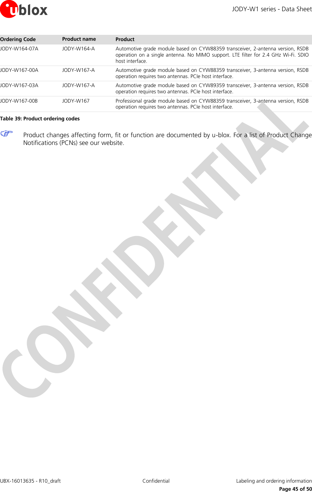
![JODY-W1 series - Data Sheet UBX-16013635 - R10_draft Confidential Labeling and ordering information Page 44 of 50 Ordering code Label marking FCC ID ISED ID Ref. 1 (Model: …) Ref. 2 JODY-W164-04A, JODY-W164-05A, JODY-W164 JODY-W164 04A-yy 05A-yy JODY-W164-03A JODY-W164 03A-yy XPYJODYW164 8595A-JODYW164 JODY-W164-07A JODY-W164 07A-yy XPYJODYW164-07A 8595A-JODYW16407A JODY-W167-00A, JODY-W167-03A, JODY-W167-00B JODY-W167 JODY-W167 JODY-W167 00A-yy 03A-yy 00B-yy XPYJODYW167 8595A-JODYW167 Table 36: Mapping of ordering code, label marking and FCC/ISED IDs. 9.2 Table Explanation of codes Two different product code formats are used. The Product Name is used in documentation such as this data sheet and identifies all u-blox products, independent of packaging and quality grade. The Ordering Code includes options and quality, while the Type Number includes the hardware and firmware versions. Table 37 explains these three different formats: Format Structure Product Name PPPP-TGVV Ordering Code PPPP-TGVV-TTQ Type Number PPPP-TGVV-TTQ-XX Table 37: Product code formats Table 38 explains the parts of the product code. Code Meaning Example PPPP Form factor JODY TG Platform T – Dominant technology, For example, W: Wi-Fi, B: Bluetooth G - Generation W1 VV Variant based on the same platform; range [00…99] 61 TT Major Product Version 00 Q Quality grade A: Automotive B: Professional C: Standard A XX Minor product version (not relevant for certification) 00 Table 38: Part identification code 9.3 Ordering codes Ordering Code Product name Product JODY-W163-04A JODY-W163-A Automotive grade module based on CYW89359 transceiver, 2-antenna version, RSDB operation on a single antenna. No MIMO support. SDIO host interface. JODY-W163-05A JODY-W163-A Automotive grade module based on CYW88359 transceiver, 2-antenna version, RSDB operation on a single antenna. No MIMO support. SDIO host interface. JODY-W164-03A JODY-W164-A Automotive grade module based on CYW89359 transceiver, 2-antenna version, RSDB operation on a single antenna. Support for 5 GHz MIMO. PCIe host interface. JODY-W164-04A JODY-W164-A Automotive grade module based on CYW89359 transceiver, 2-antenna version, RSDB operation on a single antenna. No MIMO support. PCIe host interface. JODY-W164-05A JODY-W164-A Automotive grade module based on CYW88359 transceiver, 2-antenna version, RSDB operation on a single antenna. No MIMO support. PCIe host interface.](https://usermanual.wiki/u-blox/JODYW164.Data-Sheet/User-Guide-3927160-Page-44.png)
![JODY-W1 series - Data Sheet UBX-16013635 - R10_draft Confidential Related documents Page 48 of 50 Related documents [1] u-blox Package Information Guide, document number UBX-14001652 [2] JODY-W1 series System Integration Manual, document number UBX-15024929 [3] JODY-W1 antenna reference design, document number UBX-18017767 [4] Radio Equipment Directive; http://ec.europa.eu/growth/sectors/electrical-engineering/red-directive; July 2017 For regular updates to u-blox documentation and to receive product change notifications, register on our homepage (http://www.u-blox.com).](https://usermanual.wiki/u-blox/JODYW164.Data-Sheet/User-Guide-3927160-Page-48.png)