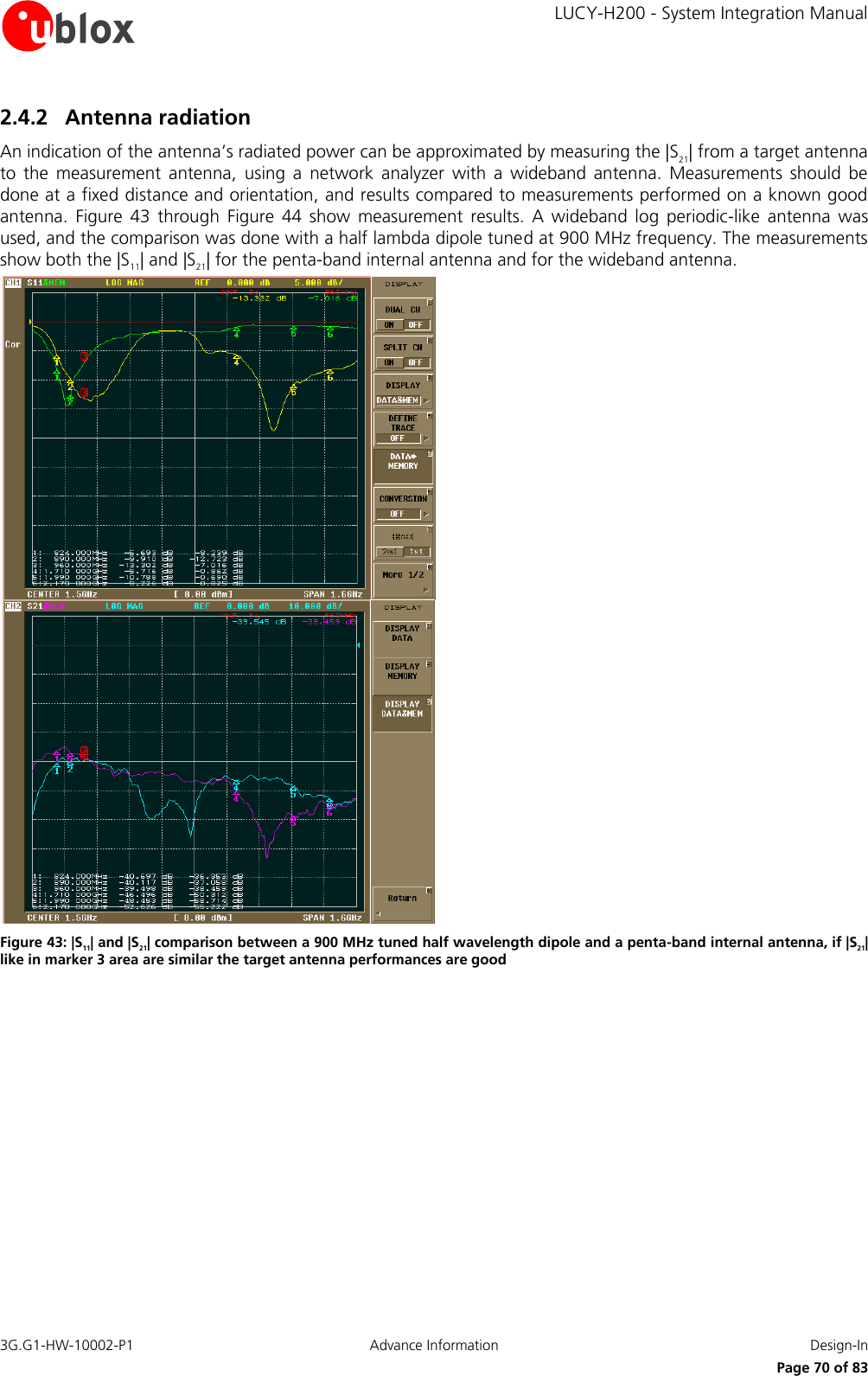
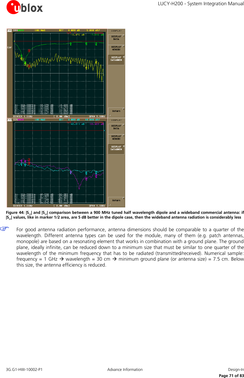
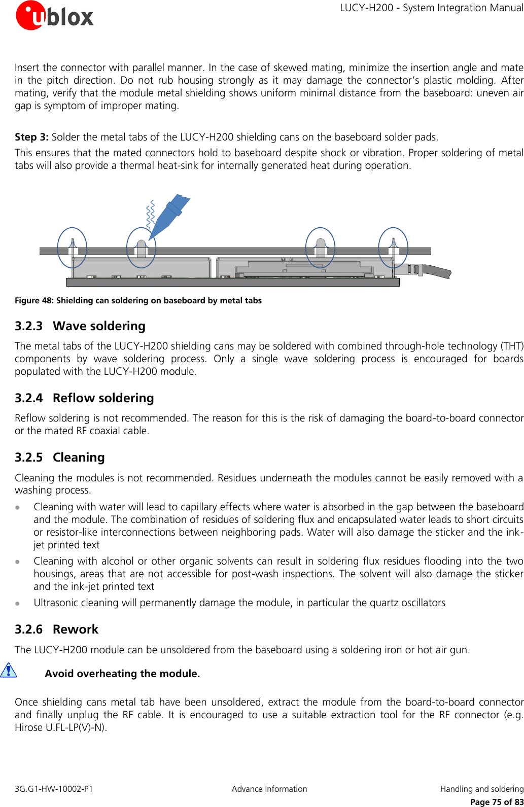
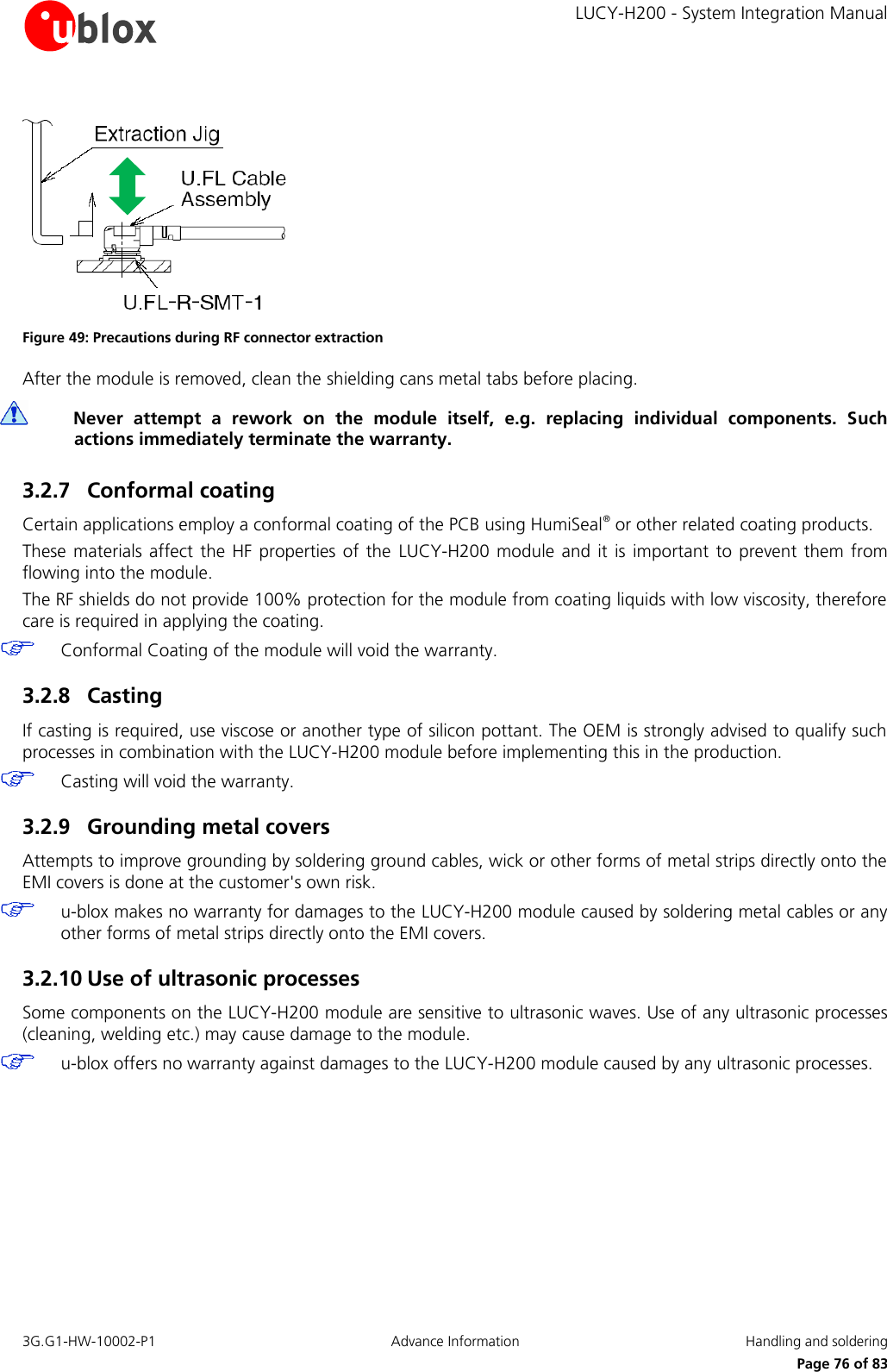
u blox LUCYH200 Quadband GSM/GPRS and Triband UMTS/HSDPA wireless module User Manual LUCY H200

u-blox AG Quadband GSM/GPRS and Triband UMTS/HSDPA wireless module LUCY H200

Contents

Users Manual

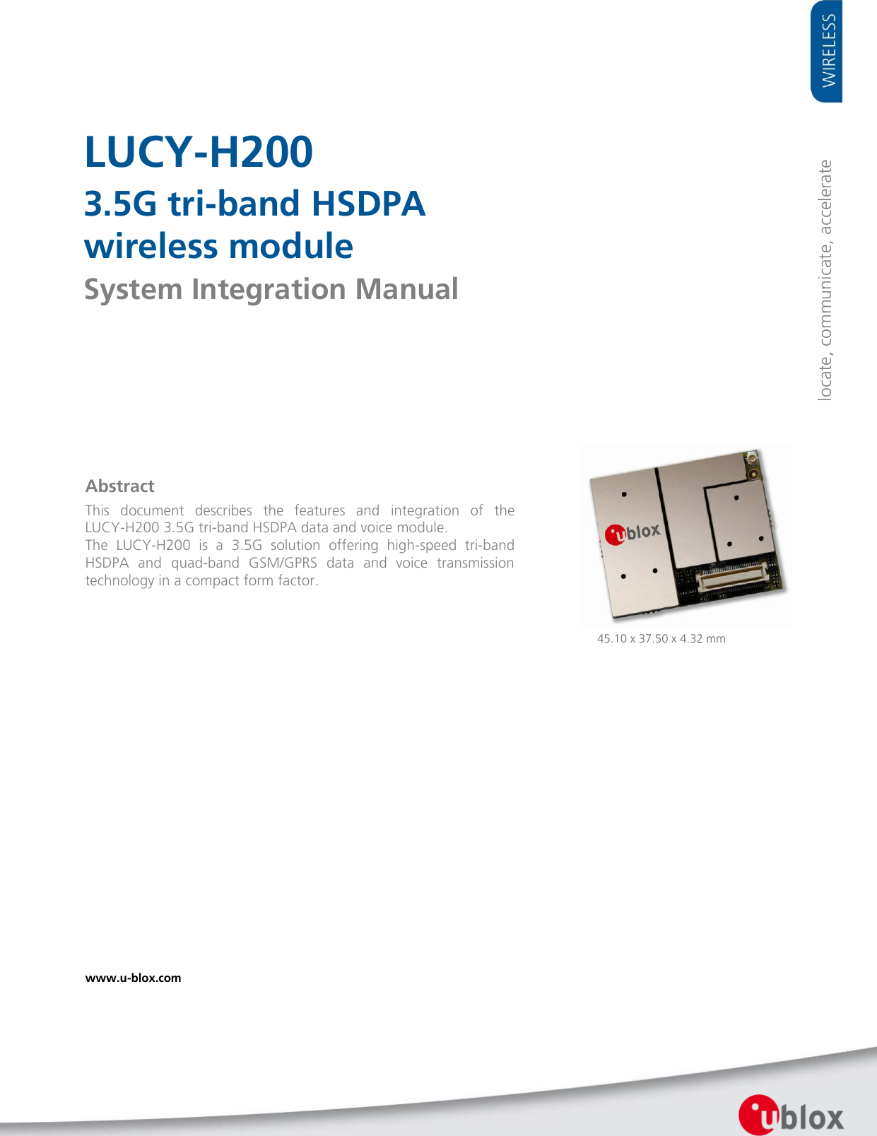
    LUCY-H200 3.5G tri-band HSDPA  wireless module System Integration Manual                Abstract This  document  describes  the  features  and  integration  of  the LUCY-H200 3.5G tri-band HSDPA data and voice module. The  LUCY-H200  is  a  3.5G  solution  offering  high-speed  tri-band HSDPA  and  quad-band  GSM/GPRS  data  and  voice  transmission technology in a compact form factor.  locate, communicate, accelerate 45.10 x 37.50 x 4.32 mm www.u-blox.com
LUCY-H200 - System Integration Manual  3G.G1-HW-10002-P1   Page 2   Document Information Title LUCY-H200 Subtitle 3.5G tri-band HSDPA  wireless module  Document type System Integration Manual  Document number 3G.G1-HW-10002-P1 Document status Advance Information  Document status information Objective Specification This document contains target values. Revised and supplementary data will be published later. Advance Information This document contains data based on early testing. Revised and supplementary data will be published later. Preliminary  This document contains data from product verification. Revised and supplementary data may be published later. Released  This document contains the final product specification.  This document applies to the following products: Name Type number Firmware version PCN reference LUCY-H200 LUCY-H200-00S-00 n.a. n.a.              This document and the use of any information contained therein, is subject to the acceptance of the u-blox terms and conditions. They can be downloaded from www.u-blox.com. u-blox makes no warranties based on the accuracy or completeness of the contents of this document and reserves the right to make changes to specifications and product descriptions at any time without notice.  u-blox reserves all rights to this document and the information contained herein. Reproduction, use or disclosure to third parties without express permission is strictly prohibited. Copyright © 2010, u-blox AG. u-blox® is a registered trademark of u-blox Holding AG in the EU and other countries.
    LUCY-H200 - System Integration Manual 3G.G1-HW-10002-P1  Advance Information  Preface      Page 3 of 83 Preface u-blox Technical Documentation As  part  of  our  commitment  to  customer  support,  u-blox  maintains  an  extensive  volume  of  technical documentation for our products. In addition to our product-specific technical data sheets, the following manuals are available to assist u-blox customers in product design and development. AT  Commands  Manual:  This  document  provides  the  description  of  the  supported  AT  commands  by  the  LUCY-H200 module to verify all implemented functionalities. System Integration Manual: This Manual provides hardware design instructions and information on  how to set up production and final product tests. Application  Note:  document  provides  general  design  instructions  and  information  that  applies  to  all  u-blox Wireless  modules.  See  Section Related  documents for  a list  of  Application  Notes  related  to  your  Wireless Module. How to use this Manual The  LUCY-H200  System  Integration  Manual  provides  the  necessary  information  to  successfully  design  in  and configure these u-blox wireless modules. This manual has a modular structure. It is not necessary to read it from the beginning to the end. The following symbols are used to highlight important information within the manual:   An index finger points out key information pertaining to module integration and performance.   A warning symbol indicates actions that could negatively impact or damage the module. Questions If you have any questions about u-blox Wireless Integration, please:  Read this manual carefully.   Contact our information service on the homepage http://www.u-blox.com   Read the questions and answers on our FAQ database on the homepage http://www.u-blox.com Technical Support Worldwide Web Our  website  (www.u-blox.com)  is  a  rich  pool  of  information.  Product  information,  technical  documents  and helpful FAQ can be accessed 24h a day. By E-mail Contact the nearest of the Technical Support offices by email. Use our service pool email addresses rather than any personal email address of our staff. This makes sure that your request is processed as soon as possible. You will find the contact details at the end of the document. Helpful Information when Contacting Technical Support When contacting Technical Support please have the following information ready:  Module type (e.g. LUCY-H200) and firmware version  Module configuration  Clear description of your question or the problem  A short description of the application  Your complete contact details
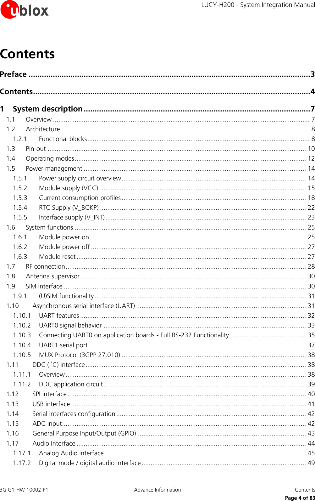
    LUCY-H200 - System Integration Manual 3G.G1-HW-10002-P1  Advance Information  Contents      Page 4 of 83 Contents Preface ................................................................................................................................ 3 Contents .............................................................................................................................. 4 1 System description ....................................................................................................... 7 1.1 Overview .............................................................................................................................................. 7 1.2 Architecture .......................................................................................................................................... 8 1.2.1 Functional blocks ........................................................................................................................... 8 1.3 Pin-out ............................................................................................................................................... 10 1.4 Operating modes ................................................................................................................................ 12 1.5 Power management ........................................................................................................................... 14 1.5.1 Power supply circuit overview ...................................................................................................... 14 1.5.2 Module supply (VCC) .................................................................................................................. 15 1.5.3 Current consumption profiles ...................................................................................................... 18 1.5.4 RTC Supply (V_BCKP) .................................................................................................................. 22 1.5.5 Interface supply (V_INT) ............................................................................................................... 23 1.6 System functions ................................................................................................................................ 25 1.6.1 Module power on ....................................................................................................................... 25 1.6.2 Module power off ....................................................................................................................... 27 1.6.3 Module reset ............................................................................................................................... 27 1.7 RF connection ..................................................................................................................................... 28 1.8 Antenna supervisor ............................................................................................................................. 30 1.9 SIM interface ...................................................................................................................................... 30 1.9.1 (U)SIM functionality ..................................................................................................................... 31 1.10 Asynchronous serial interface (UART) .............................................................................................. 31 1.10.1 UART features ............................................................................................................................. 32 1.10.2 UART0 signal behavior ................................................................................................................ 33 1.10.3 Connecting UART0 on application boards - Full RS-232 Functionality .......................................... 35 1.10.4 UART1 serial port ........................................................................................................................ 37 1.10.5 MUX Protocol (3GPP 27.010) ...................................................................................................... 38 1.11 DDC (I2C) interface .......................................................................................................................... 38 1.11.1 Overview ..................................................................................................................................... 38 1.11.2 DDC application circuit ................................................................................................................ 39 1.12 SPI interface .................................................................................................................................... 40 1.13 USB interface .................................................................................................................................. 41 1.14 Serial interfaces configuration ......................................................................................................... 42 1.15 ADC input ....................................................................................................................................... 42 1.16 General Purpose Input/Output (GPIO) ............................................................................................. 43 1.17 Audio Interface ............................................................................................................................... 44 1.17.1 Analog Audio interface ............................................................................................................... 45 1.17.2 Digital mode / digital audio interface ........................................................................................... 49
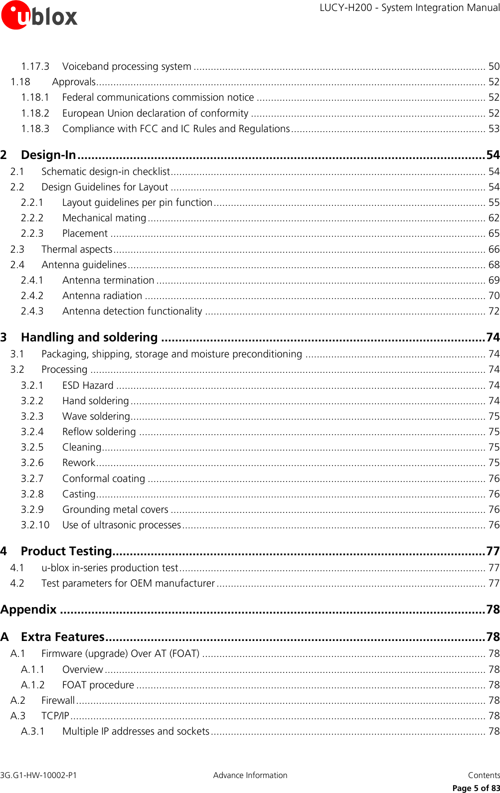
    LUCY-H200 - System Integration Manual 3G.G1-HW-10002-P1  Advance Information  Contents      Page 5 of 83 1.17.3 Voiceband processing system ...................................................................................................... 50 1.18 Approvals ........................................................................................................................................ 52 1.18.1 Federal communications commission notice ................................................................................ 52 1.18.2 European Union declaration of conformity .................................................................................. 52 1.18.3 Compliance with FCC and IC Rules and Regulations .................................................................... 53 2 Design-In ..................................................................................................................... 54 2.1 Schematic design-in checklist .............................................................................................................. 54 2.2 Design Guidelines for Layout .............................................................................................................. 54 2.2.1 Layout guidelines per pin function ............................................................................................... 55 2.2.2 Mechanical mating ...................................................................................................................... 62 2.2.3 Placement ................................................................................................................................... 65 2.3 Thermal aspects .................................................................................................................................. 66 2.4 Antenna guidelines ............................................................................................................................. 68 2.4.1 Antenna termination ................................................................................................................... 69 2.4.2 Antenna radiation ....................................................................................................................... 70 2.4.3 Antenna detection functionality .................................................................................................. 72 3 Handling and soldering ............................................................................................. 74 3.1 Packaging, shipping, storage and moisture preconditioning ............................................................... 74 3.2 Processing .......................................................................................................................................... 74 3.2.1 ESD Hazard ................................................................................................................................. 74 3.2.2 Hand soldering ............................................................................................................................ 74 3.2.3 Wave soldering............................................................................................................................ 75 3.2.4 Reflow soldering ......................................................................................................................... 75 3.2.5 Cleaning ...................................................................................................................................... 75 3.2.6 Rework ........................................................................................................................................ 75 3.2.7 Conformal coating ...................................................................................................................... 76 3.2.8 Casting ........................................................................................................................................ 76 3.2.9 Grounding metal covers .............................................................................................................. 76 3.2.10 Use of ultrasonic processes .......................................................................................................... 76 4 Product Testing........................................................................................................... 77 4.1 u-blox in-series production test ........................................................................................................... 77 4.2 Test parameters for OEM manufacturer .............................................................................................. 77 Appendix .......................................................................................................................... 78 A Extra Features ............................................................................................................. 78 A.1 Firmware (upgrade) Over AT (FOAT) ................................................................................................... 78 A.1.1 Overview ..................................................................................................................................... 78 A.1.2 FOAT procedure .......................................................................................................................... 78 A.2 Firewall ............................................................................................................................................... 78 A.3 TCP/IP ................................................................................................................................................. 78 A.3.1 Multiple IP addresses and sockets ................................................................................................ 78
    LUCY-H200 - System Integration Manual 3G.G1-HW-10002-P1  Advance Information  Contents      Page 6 of 83 A.4 FTP ..................................................................................................................................................... 79 A.5 FTPS ................................................................................................................................................... 79 A.6 HTTP ................................................................................................................................................... 79 A.7 HTTPS ................................................................................................................................................. 79 A.8 SMTP .................................................................................................................................................. 79 A.9 GPS .................................................................................................................................................... 79 B Glossary ...................................................................................................................... 80 Related documents........................................................................................................... 82 Revision history ................................................................................................................ 82 Contact .............................................................................................................................. 83
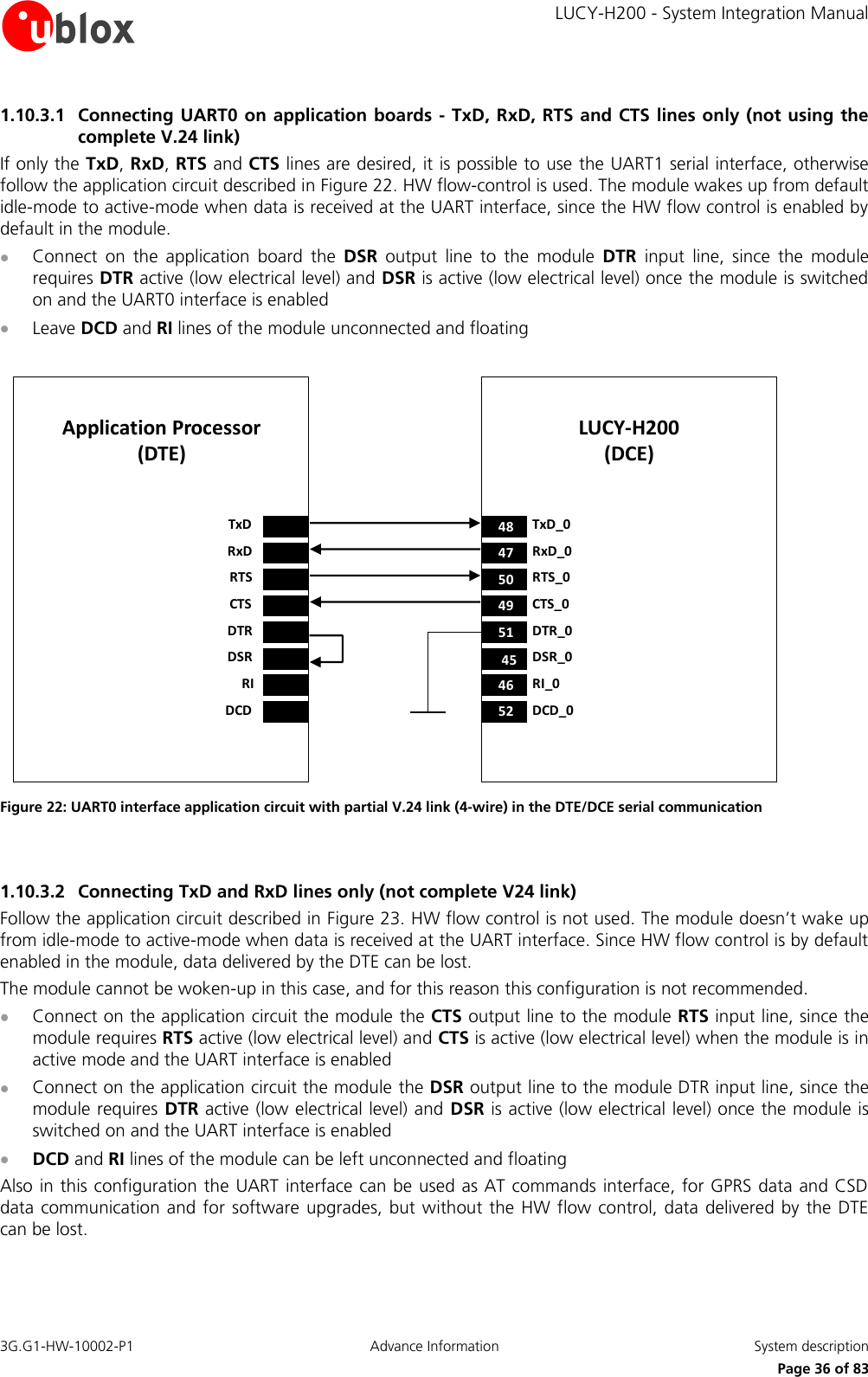
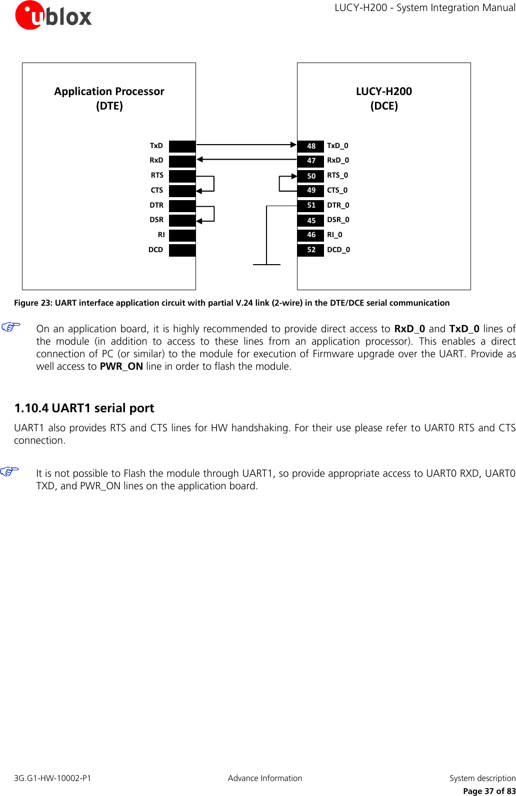
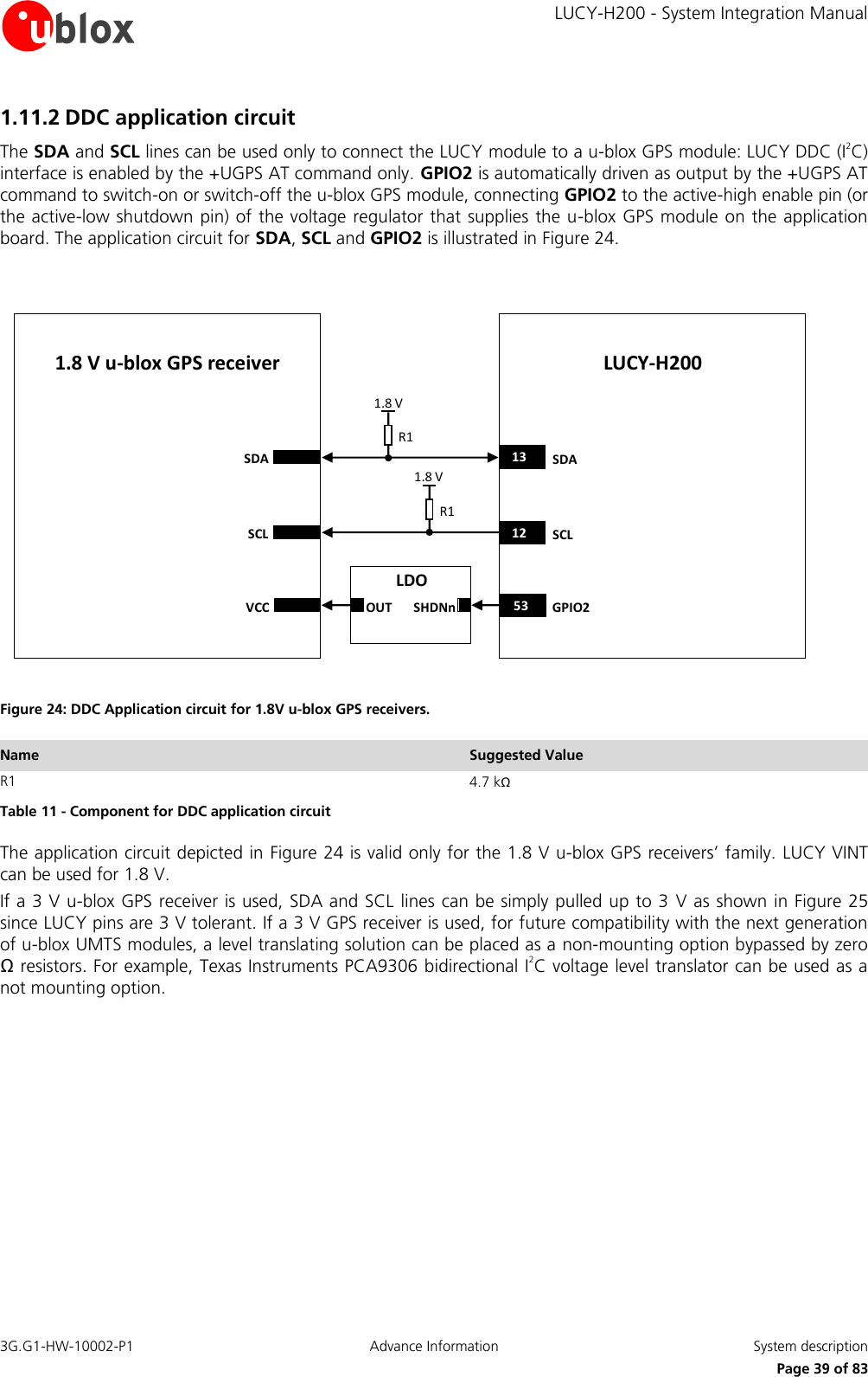
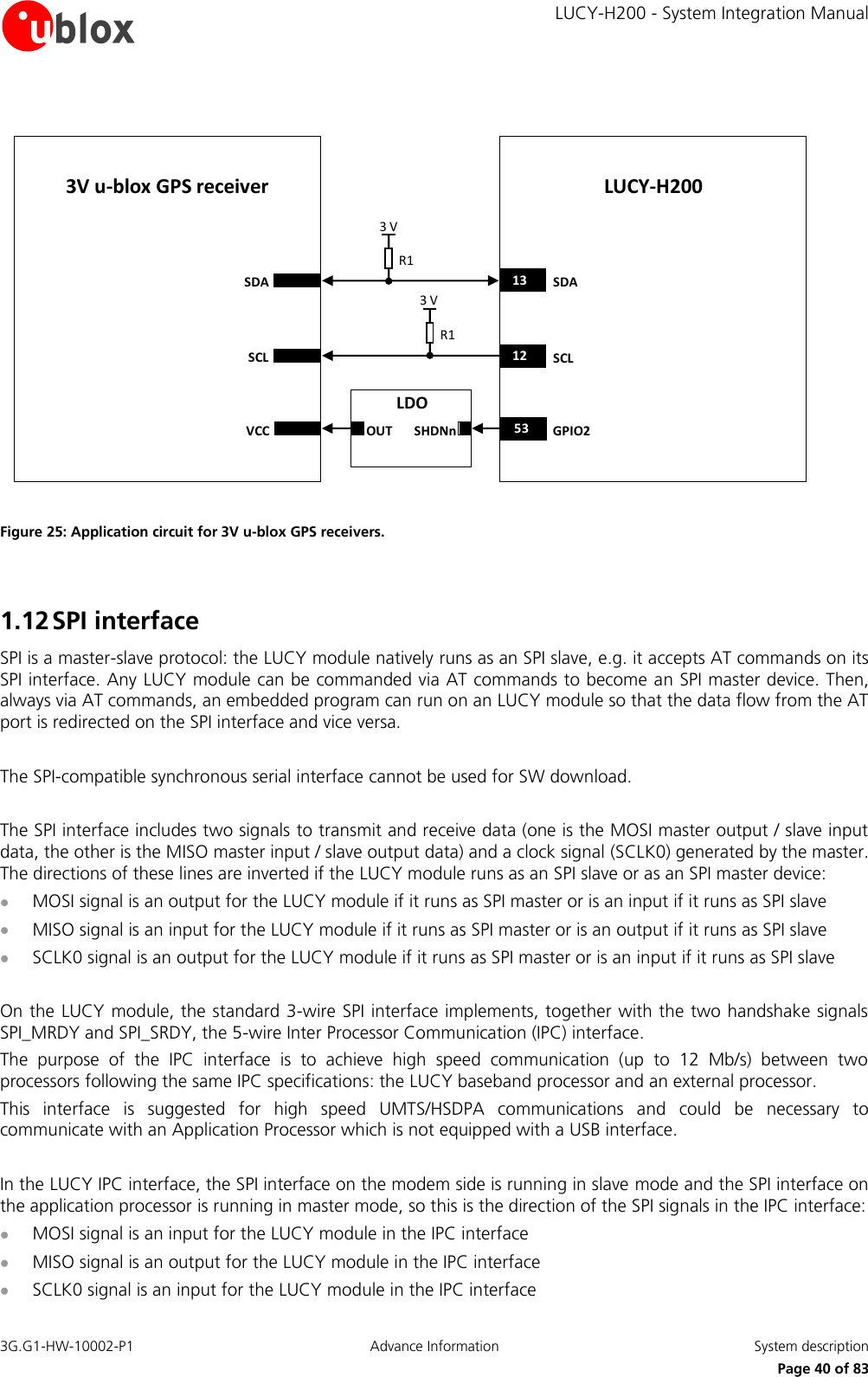
    LUCY-H200 - System Integration Manual 3G.G1-HW-10002-P1  Advance Information  System description      Page 7 of 83 1 System description 1.1 Overview The LUCY-H200 module from u-blox integrates a full-feature Release 5 UMTS/HSDPA GSM/GPRS/EDGE protocol stack.  UMTS/HSDPA characteristics:  UMTS Terrestrial Radio Access (UTRA) Frequency Division Duplex (FDD) operating mode  Tri-bands: UMTS Band I (2100 MHz), Band II (1900 MHz), Band V (850 MHz)  Power class 3 (24 dBm) for WCDMA/HSDPA mode  HSDPA category 8, up to 7.2 Mb/s download, 384 kb/s upload  WCDMA PS data up to 384 kb/s UL/DL  WCDMA CS data up to 64 kb/s UL/DL GSM/GPRS/EDGE characteristics:  Quad-band support: GSM 850 MHz, EGSM 900 MHz, DCS 1800 MHz and PCS 1900 MHz  Power class 4 (33 dBm) for GSM/EGSM bands  Power class 1 (30 dBm) for DCS/PCS bands  EDGE Power Class ES2 (27 dBm) for GSM/EGSM bands  EDGE Power Class ES2 (26 dBm) for DCS/PCS bands  EDGE multislot class 12, coding scheme MCS1-MCS9, up to 236.8 kb/s  GPRS multislot class 12, coding scheme CS1-CS4, up to 85.6 kb/s  CSD Non-transparent / Transparent mode, up to 9.6 kb/s  DTM class 11   Mobile Station class A for UMTS mode and Class B for E-GPRS/GPRS mode   Network Operation Mode I,II,III   Modem type V.32, V.110   Fax Group 3, Class 2.0   TCP/IP stack  IPv4 support  The 3G modem is a Class A User Equipment: the device can work simultaneously on the GSM and GPRS/UMTS networks.  Basically  this  means  that  voice  calls  are  possible  while  the  data  connection  is  active  without  any interruption in service. The GPRS modem is a Class B Mobile Station; this means the data module can be attached to both GPRS and GSM services, using one service at a time. For instance, if during data transmission an incoming call occurs, the data connection is suspended to permit the voice communication. Once the voice call has terminated, the data service  is  resumed.  Network  operation  modes  I  to  III  are  supported,  with  user-definable  preferred  service selectable from GSM to GPRS. Optionally paging messages for GSM calls can be monitored during GPRS data transfer in not-coordinating network operation mode NOM II-III. PBCCH/PCCCH logical channels are supported, as well as CBCH reception. CBCH reception when on PBCCH is supported. The LUCY-H200 module implements a GPRS/EGPRS class 12 for data transfer. GPRS class determines the number of  timeslots  available  for  upload  and  download  and  thus  the  speed  at  which  data  can  be  transmitted  and
    LUCY-H200 - System Integration Manual 3G.G1-HW-10002-P1  Advance Information  System description      Page 8 of 83 received, with higher classes typically allowing faster data transfer rates. GPRS multislot 12 implies a maximum of 4 slots in download (reception) and 4 slots in upload (transmission) with 5 slots in total. The  network  automatically  configures  the  number  of  timeslots  used  for  reception  or  transmission  (voice  calls take precedence over GPRS traffic). The network also automatically configures channel encoding (CS1 to MCS9). The maximum (E)GPRS bit rate of the mobile station depends on the coding scheme and number of time slots.  1.2 Architecture WirelessBase-bandProcessorMemoryPowerMgmtUnitRF Transceiver26 MHz 32.768 kHzLNA SAW3G PA(s)2G PA FEMANTBase-BandRF TransceiverRF High-Power(U)SIM CardSPIUSBGPIO(s)ADC1Analog AudioDDC (for GPS)UART0UART1Digital Audio (I2S)Power ONExternal ResetVcc (Battery)V_BCKP (RTC)V_INT (I/O)Figure 1: LUCY-H200 block diagram  1.2.1 Functional blocks The user interfaces on the LUCY-H200 module are the RF antenna and the board-to-board connector. The antenna is the interface for RF signals toward the wide-area network air interface. The user has freedom in choosing the antenna. The following dedicated section provides more details. The  board-to-board  connector  is  the  main  interface  for  the  user  application,  where  all  the  supplies  and input/output signals are connected. Detailed description of  the board-to-board connector characteristics is one of the main purposes of this document, please see following sections Between the RF air-interface and the board-to-board connector the LUCY-H200 functions by means of efficient and specialized hardware which can be grouped into the following functional blocks: RF high power front-end, RF transceiver, Baseband section and Power Management unit. RF high-power front-end A separated shielding chamber includes the RF high-power signal circuitry, namely:  Quad-band 2G EDGE/GSM Power Amplifier (PA) module  Three HSDPA/UMTS Power Amplifier module with integrated duplexers  Front-End Module (FEM) with antenna switch multiplexer and integrated SAW filters for 2G receiver The RF antenna is directly connected to the FEM, which dispatches the RF signals according to the active mode. For time-duplex 2G operation, the incoming signal at the active RX slot is applied to integrated SAW filters for out-of-band rejection and then sent to the appropriate receiver port of the RF transceiver. During the allocated TX slots, the low level signal coming from the RF transceiver is enhanced by the 2G power amplifier module and
    LUCY-H200 - System Integration Manual 3G.G1-HW-10002-P1  Advance Information  System description      Page 9 of 83 then directed to the antenna through the FEM. The 3G transmitter and receiver are instead active at the same time due to frequency-domain duplex operation. The switch integrated in the FEM connects the antenna port to the  passive  duplexer  which  separates  the  TX  and  RX  signals  path.  The  duplexer  itself  provides  front-end  RF filtering for RX band selection while combining the amplified TX signal coming from the fixed gain linear power amplifier. RF Transceiver A second shielding box includes all the low-level analog RF components, namely:  Tri-band HSDPA/WCDMA and quad-band EDGE/GSM transceiver  Voltage Controlled Temperature Compensated 26 MHz Crystal Oscillator (VC-TCXO)  Low Noise Amplifier (LNA) and SAW RF filters for 3G receivers While  operating  in  3G  mode,  the  RF  transceiver  performs  direct  up-conversion  and  down-conversion  of  the baseband I/Q signals, with the RF voltage controlled gain amplifier being used to set the uplink TX power. In the downlink path, the external  LNA enhances the  RX sensitivity while  discrete inter-stage SAW filters additionally improve  the  rejection  of  out-of-band blockers.  An  internal  programmable  gain  amplifier  is  used  to  cope  with automatic  gain  control  algorithm  before  to  deliver  the  analog  I/Q  signal  to  baseband  for  further  digital processing. For  2G  operations,  a  constant  gain  direct  conversion  receiver  with  integrated  LNAs  and  highly  linear  RF quadrature demodulator are used to provide the same I/Q signals to baseband as well. In transmit mode, the up-conversion is implemented by means of a digital sigma-delta transmitter or polar modulator depending on the modulation to be transmitted. In all the modes, a fractional-N sigma-delta RF synthesizer and an on-chip 3.8–4 GHz voltage controlled oscillator are used to generate the local oscillator signal. The frequency reference to RF oscillators is provided by the 26 MHz VC-TCXO. The same signal is buffered to the baseband as a master reference for clock generation circuits while operating in active mode. Baseband section and power management unit The  largest  shielding  box  includes  all  the  digital  circuitry  and  the  power  supplies,  basically  the  following functional blocks:  Wireless baseband processor, a mixed signal ASIC which integrates:  ARM Microprocessor for controller functions, 2G & 3G upper layer software  DSP core for 2G Layer 1 and audio processing  3G coprocessor and HW accelerator for 3G Layer 1 control software and routines  Dedicated HW for peripherals control, as UART, USB, SPI etc  Memory system in a Multi-Chip Package (MCP) integrating two devices:  NOR flash non-volatile memory  DDR SRAM volatile memory  Power Management Unit (PMU), used to derive from Main Battery supply VCC all the supply voltages for the system  32.768 kHz crystal, connected to the oscillator of the Real Time Clock (RTC) to perform the clock reference in idle or power-off mode
    LUCY-H200 - System Integration Manual 3G.G1-HW-10002-P1  Advance Information  System description      Page 10 of 83 1.3 Pin-out Table 1 describes the pin-out of the board-to board connector for the LUCY-H200 module, with pins grouped by function. Function Pin No I/O Description Remarks Power VCC 57, 58, 59, 60 I Module Supply Clean and stable supply is required: low ripple and low voltage drop must be guaranteed. Voltage provided must always be above the minimum limit of the operating range. Consider that there are large current spikes in connected mode, when a GSM call is enabled. See section 1.5.2 VCC pins are internally connected. GND 1, 2, 3, 4, 19, 22, 25, 42 N/A Ground GND pins are internally connected but a good (low impedance) external ground can improve RF performances. V_BCKP 55 I/O Real Time Clock supply V_BCKP = 2.0 V (typical) generated by the module to supply Real Time Clock when VCC supply voltage is within valid operating range. See section 1.5.4 V_INT 56 O Interface supply V_INT = 1.8V (typical) generated by the module and used as supply rail for all I/O. See section 1.5.5 VSIM 5 O SIM supply SIM supply automatically generated by the module. See section 1.9 SIM SIM_IO 6 I/O SIM data SIM interface: see section 1.9. Internal 4.7 kΩ pull-up to VSIM. Must meet SIM specifications SIM_CLK 7 O SIM clock SIM interface: see section 1.9. Must meet SIM specifications SIM_RST 8 O SIM reset SIM interface: see section 1.9. Must meet SIM specifications SPI SPI_MISO 9 I/O SPI Master Input,  Slave Output The pin by default is set to output. SPI default is Slave mode. Internal active pull-up to 1.8 V is enabled when the pin is used as input. SPI_MOSI 10 I/O SPI Master Output,  Slave Input The pin by default is set to input. SPI default is Slave mode. Internal active pull-up to 1.8 V is enabled when the pin is used as input. SPI_SCLK0 11 I/O SPI Serial Clock, output from Master Input if Slave and Output if Master. SPI default is Slave mode SPI_SRDY 32 O SPI Slave Ready   SPI_MRDY 38 I SPI Master Ready  Internal active pull-up to 1.8 V is enabled. DDC SCL 12 O I2C bus clock line Fixed open drain. External pull-up required. See section 1.10 SDA 13 I/O I2C bus data line Fixed open drain. External pull-up required. See section 1.10 UART0 DSR_0 45 O UART0 data set ready See section 1.10. Control convention of the pins RI_0 46 O UART0 ring indicator See section 1.10. Control convention of the pins RxD_0 47 O UART0 received data  See section 1.10. Control convention of the pins TxD_0 48 I UART0 transmitted data Internal active pull-up to 1.8 V enabled. See section 1.10. Control convention of the pins CTS_0 49 O UART0 clear to send  See section 1.10. Control convention of the pins RTS_0 50 I UART0 ready to send Internal active pull-up to 1.8 V enabled. See section 1.10. Control convention of the pins DTR_0 51 I UART0 data terminal ready Internal active pull-up to 1.8 V enabled. See section 1.10. Control convention of the pins DCD_0 52 O UART0 data carrier See section 1.10. Control convention of the pins
    LUCY-H200 - System Integration Manual 3G.G1-HW-10002-P1  Advance Information  System description      Page 11 of 83 Function Pin No I/O Description Remarks detect UART1 RxD_1 43 O UART1 received data  See section 1.10. Control convention of the pins TxD_1 44 I UART1 transmitted data Internal active pull-up to 1.8 V enabled. See section 1.10. Control convention of the pins CTS_1 40 O UART1 clear to send  See section 1.10. Control convention of the pins RTS_1 33 I UART1 ready to send Internal active pull-up to 1.8 V enabled. See section 1.10. Control convention of the pins ADC ADC1 27 I ADC input Resolution: 12 bits. See section 1.10; consider that the impedance of this input changes depending on the operative mode GPIO GPIO1 54 I/O GPIO See section 1.16. GPIO2 53 I/O GPIO See section 1.16. GPIO3 41 I/O GPIO See section 1.16. GPIO4 39 I/O GPIO See section 1.16. GPIO5 31 I/O GPIO See section 1.16. USB VUSB_DET 28 I USB detect input  USB_D+ 29 I/O USB Data Line D+ Internal pull up available so external pull-up not needed. USB_D- 30 I/O USB Data Line D-  System PWR_ON 26 I Power-on input Pin has internal pull-up. See section 1.6.1 RESET_N 18 I External reset input Pin has internal pull-up. See section 1.6.3 Audio I2S_CLK 14 O I2S clock I2S Interface: see section 1.17.2. Check device specifications to ensure compatibility of supported modes to LUCY-H200 module. I2S_RXD 15 I I2S receive data I2S Interface: see section 1.17.2. Internal active pull-up to 1.8V enabled. Check device specifications to ensure compatibility of supported modes to LUCY-H200 module. I2S_TXD 16 O I2S transmit data I2S Interface: see section 1.17.2. Check device specifications to ensure compatibility of supported modes to LUCY-H200 module.  I2S_WA 17 O I2S word alignment I2S Interface: see section 1.17.2. Check device specifications to ensure compatibility of supported modes to LUCY-H200 module.  MIC_GND 20 I Microphone analog reference Local ground of microphone. Audio pin: see section 1.17.1 MIC_BIAS 21 I Microphone analog signal input and bias output This audio input is used for audio uplink path. Audio pin: see section 1.17.1 SPK_P 23 O Speaker output with high power differential analog audio This audio output is used when audio downlink path is “Loudspeaker“. Audio pin: see section 1.17.1 SPK_N 24 O Speaker output with power differential analog audio output This audio output is used when audio downlink path is “Loudspeaker“. Audio pin: see section 1.17.1 Reserved Reserved 34   Do not connect Reserved 35   Do not connect Reserved 36   Do not connect Reserved 37   Do not connect Table 1: LUCY-H200 pin-out
    LUCY-H200 - System Integration Manual 3G.G1-HW-10002-P1  Advance Information  System description      Page 12 of 83 1.4 Operating modes The  LUCY-H200  module  includes  several  operating  modes,  each  have  different  active  features  and  interfaces. Table 2 summarizes the various operating modes and provides general guidelines for operation.  General Status Operating Mode Description Features / Remarks Power-down Not-Powered Mode VCC supply not present or below normal operating range. Microprocessor not operating. RTC only operates if supplied through V_BCKP pin. Module is switched off. Module cannot be switched on by a falling edge provided on the PWR_ON input, neither by a preset RTC alarm, or a rising edge to a valid range of USB voltage provided on the VUSB_DET input. Application interfaces not accessible. Internal RTC timer operates only if a valid voltage is applied to V_BCKP pin. Power-Off Mode VCC supply within normal operating range. Microprocessor not operating. Only RTC runs. Module is switched off: normal shutdown after sending the AT+CPWROFF command (refer to u-blox 3.5G HSDPA AT Commands Manual [2]). Module can be switched on by a falling edge provided on the PWR_ON input, by a preset RTC alarm, or a rising edge to a valid voltage for USB VBUS detection provided on the VUSB_DET inputs. Application interfaces are not accessible. Only the internal RTC timer in operation. Normal operation Idle-Mode Microprocessor runs with 32 kHz as reference oscillator. Module does not accept data signals from an external device. Module is switched on and is in idle mode (i.e. power saving / sleep mode). Application interfaces disabled. Module by default does not enter automatically in idle mode; this happens only if this mode is enabled by appropriate AT command (refer to u-blox 3.5G HSDPA AT Commands Manual [2]). If module is registered with the network, and idle mode is enabled, it automatically enters idle mode and periodically wakes up to active mode to monitor the paging channel for the paging block reception according to network indication. If module is not registered with the network, and idle mode is enabled, it automatically goes in idle mode and periodically wakes up to monitor external activity. Module wakes up from idle mode to active mode if an RTC alarm occurs. Module wakes up from idle mode to active mode when data received on UART interface with HW flow control enabled. Module wakes up from idle mode to active mode if a voice or data call incoming. Module wakes up from idle mode to active mode when the RTS input line is set to the ON state by the DTE if the AT+UPSV=2 command is sent to the module (feature not enabled by default). The hardware flow control output (CTS line) indicates when the module is in idle (power saving mode): the line is driven in the OFF state when the module is not prepared to accept data signals. Module wakes up from idle mode to active mode if a valid VBUS voltage is detected on VUSB_DET pin: the UART0 interface is then disabled and USB becomes active. When USB is active, the external interface connected to UART0 RTS_0 and CTS_0 should be tri-stated , see section 1.13 Active-Mode Microprocessor runs with 26 MHz as reference oscillator. The module is prepared to accept data signals from an external device. Module is switched on and is fully active: power saving is not enabled. The application interfaces are enabled.
    LUCY-H200 - System Integration Manual 3G.G1-HW-10002-P1  Advance Information  System description      Page 13 of 83 General Status Operating Mode Description Features / Remarks Connected-Mode Voice or data call enabled. Microprocessor runs with 26 MHz as reference oscillator. Module is prepared to accept data signals from an external device. The module is switched on and a voice call or a data call (GSM/GPRS/UMTS) is in progress. Module is fully active. Application interfaces are enabled. When call terminates, module returns to the last operating state (Idle or Active). Table 2: Module operating modes summary  Transition between the different modes is described in Figure 2.  Not poweredPower offActiveConnected IdleApply VCC1. If idle is enabled and no activity for at least 20 seconds or 2. no 5 V at VUSB_DET User or network activity (serial activity, USB activity, Interrupt,Network notification of incoming call)AT+CPWROFFIncoming/outgoing call or other dedicated device network communicationCall terminated, communication droppedRemove VCCSwitch ON:•PWR_ON•5V@USB_DET•VRTC interrupt Figure 2: Operating modes transition
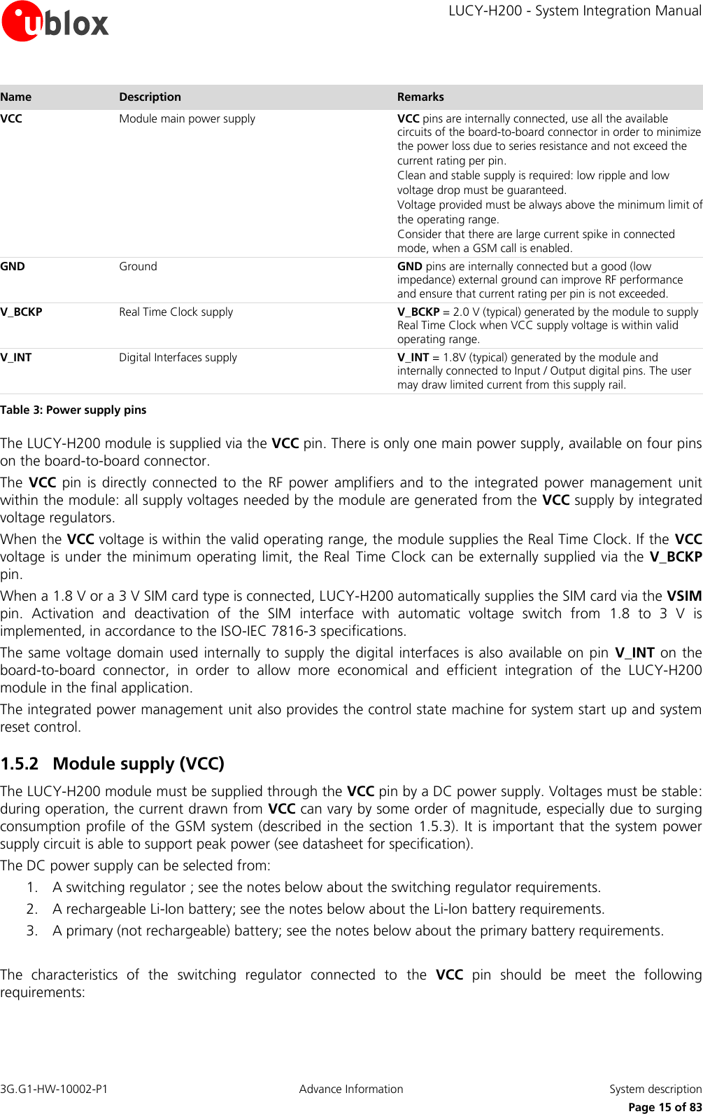
    LUCY-H200 - System Integration Manual 3G.G1-HW-10002-P1  Advance Information  System description      Page 14 of 83 1.5 Power management 1.5.1 Power supply circuit overview The LUCY-H200 module features a power management concept optimized for the most efficient use of supplied power. This is achieved by hardware  design utilizing power efficient circuit topology  (Figure 3), and by power management software controlling the power saving mode of the module. Baseband Processor2G Power AmplifierSwitching Step-DownLUCY-H200100 µF60VCC59VCC58VCC57VCC5VSIM55V_BCKP56V_INT3 x 3G Power Amplifier(s)Linear LDOLinear LDOSwitching Step-DownLinear LDOLinear LDOLinear LDOI/OEBUCOREAnalogSIMRTCNOR FlashDDR SRAMRF TransceiverMemoryPower Management  Unit Figure 3: Power management simplified block diagram Pins of the board-to board connector used by power supply function are reported on Table 3.
    LUCY-H200 - System Integration Manual 3G.G1-HW-10002-P1  Advance Information  System description      Page 15 of 83 Name Description Remarks VCC Module main power supply VCC pins are internally connected, use all the available circuits of the board-to-board connector in order to minimize the power loss due to series resistance and not exceed the current rating per pin. Clean and stable supply is required: low ripple and low voltage drop must be guaranteed. Voltage provided must be always above the minimum limit of the operating range. Consider that there are large current spike in connected mode, when a GSM call is enabled. GND Ground GND pins are internally connected but a good (low impedance) external ground can improve RF performance and ensure that current rating per pin is not exceeded. V_BCKP Real Time Clock supply V_BCKP = 2.0 V (typical) generated by the module to supply Real Time Clock when VCC supply voltage is within valid operating range. V_INT Digital Interfaces supply V_INT = 1.8V (typical) generated by the module and internally connected to Input / Output digital pins. The user may draw limited current from this supply rail.  Table 3: Power supply pins The LUCY-H200 module is supplied via the VCC pin. There is only one main power supply, available on four pins on the board-to-board connector. The  VCC  pin  is directly connected  to the  RF  power  amplifiers  and  to  the  integrated  power  management  unit within the module: all supply voltages needed by the module are generated from the VCC supply by integrated voltage regulators. When the VCC voltage is within the valid operating range, the module supplies the Real Time Clock. If the VCC voltage is under the minimum operating limit, the Real  Time Clock can be externally supplied via the  V_BCKP pin. When a 1.8 V or a 3 V SIM card type is connected, LUCY-H200 automatically supplies the SIM card via the VSIM pin.  Activation  and  deactivation  of  the  SIM  interface  with  automatic  voltage  switch  from  1.8  to  3  V  is implemented, in accordance to the ISO-IEC 7816-3 specifications. The same voltage domain used internally to supply the digital interfaces is also available on pin  V_INT on the board-to-board  connector,  in  order  to  allow  more  economical  and  efficient  integration  of  the  LUCY-H200 module in the final application. The integrated power management unit also provides the control state machine for system start up and system reset control. 1.5.2 Module supply (VCC) The LUCY-H200 module must be supplied through the VCC pin by a DC power supply. Voltages must be stable: during operation, the current drawn from VCC can vary by some order of magnitude, especially due to surging consumption profile of the GSM system (described in the section  1.5.3). It is important that the system power supply circuit is able to support peak power (see datasheet for specification). The DC power supply can be selected from: 1. A switching regulator ; see the notes below about the switching regulator requirements. 2. A rechargeable Li-Ion battery; see the notes below about the Li-Ion battery requirements. 3. A primary (not rechargeable) battery; see the notes below about the primary battery requirements.  The  characteristics  of  the  switching  regulator  connected  to  the  VCC  pin  should  be  meet  the  following requirements:
    LUCY-H200 - System Integration Manual 3G.G1-HW-10002-P1  Advance Information  System description      Page 16 of 83  power  capabilities:  the  switching  regulator  with  its  output  circuit  must  be  capable  of  providing  a  valid voltage value to the VCC pin and must be capable of delivering 2.5 A current pulses with 1/8 duty cycle to the VCC pin  low output ripple: the switching regulator with its output circuit must be capable of providing a clean (low noise) VCC voltage profile  fixed  switching  frequency  greater  or  equal  to  1  MHz:  variable  or  lower  switching  frequency  will  produce noise  in  the  VCC  voltage  profile  so  that  the  module  will  not  reach  the  GSM  modulation  spectrum requirements   fixed PWM  mode operation:  PFM mode  and  PFM/PWM modes transitions  must  be  avoided to reduce  the noise on the VCC voltage profile  The  characteristics  of  the  rechargeable  Li-Ion  battery  connected  to  the  VCC  pin  should  meet  the  following requirements:  maximum DC/pulse discharge current: the rechargeable Li-Ion battery with its output circuit must be capable of delivering 2.5 A current pulses with 1/8 duty cycle to the VCC pin  DC series  resistance: the  rechargeable  Li-Ion  battery  with  its  output circuit  must be  capable  of  avoiding a VCC voltage drop greater than 400 mV  The characteristics of the primary (not rechargeable) battery connected to the  VCC pin are compliant with the following requirements:  maximum DC/pulse discharge current: the not-rechargeable battery with its output circuit must be capable of delivering 2.5 A current pulses with 1/8 duty cycle to the VCC pin  DC series  resistance: the  rechargeable  Li-Ion  battery  with  its  output circuit  must be  capable  of  avoiding a VCC voltage drop greater than 400 mV  The  voltage  provided  to  the  VCC  pin  must  be  within  the  normal  operating  range  limits  specified  in  the  LUCY-H200  Data  Sheet  [1].  Complete  functionality  of  the  module  is  only  guaranteed  within  the  specified minimum and maximum VCC voltage range.    Ensure  that  the  input  voltage  at  VCC  is  above  the  normal  operating range  minimum  limit  to  enable  the switch-on of the module. Note that the module cannot be switched on if the  VCC voltage value is below the minimum specified limit. See the LUCY-H200 Data Sheet [1].  When  the  LUCY-H200  module  is  in  operation,  the  voltage  provided  to  the  VCC  pin  can  exceed  the  normal operating range limits but must be within the extended operating range limits specified in the  LUCY-H200 Data Sheet [1]. Module reliability is only guaranteed within this specified operational extended voltage range.    Ensure that the input voltage  at the  VCC pin never drops below the extended operating range minimum limit  when  the  module  is  switched  on,  not  even  during  a  GSM  transmit  burst,  where  the  current consumption can rise up to peaks of 2.5 A in case of a mismatched antenna load. The module switches off when the VCC voltage value drops below the minimum limit.    Operation above the extended operating range maximum limit is not recommended and extended exposure beyond it may affect device reliability.    Stress  beyond  the  VCC  absolute  maximum  ratings  may  cause  permanent  damage  to  the  module:  if necessary,  voltage  spikes  beyond  VCC  absolute  maximum  ratings  must  be  limited  to  values  within  the specified boundaries by using appropriate protection.
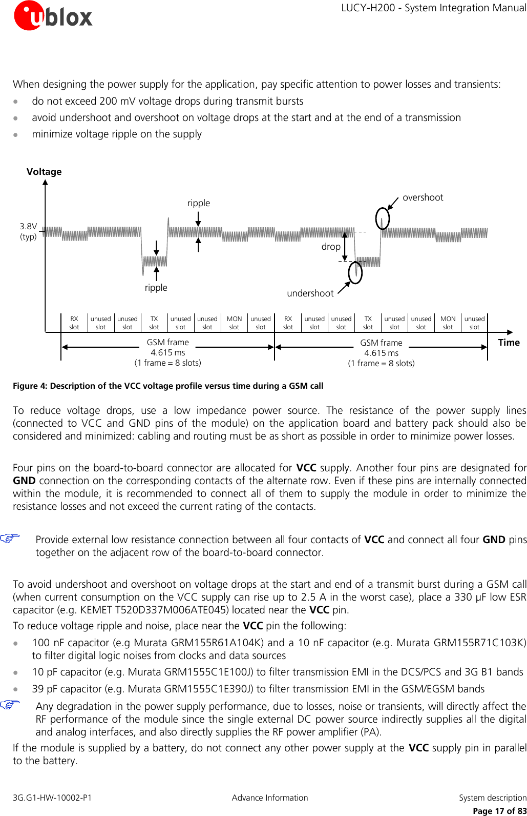
    LUCY-H200 - System Integration Manual 3G.G1-HW-10002-P1  Advance Information  System description      Page 17 of 83  When designing the power supply for the application, pay specific attention to power losses and transients:   do not exceed 200 mV voltage drops during transmit bursts   avoid undershoot and overshoot on voltage drops at the start and at the end of a transmission  minimize voltage ripple on the supply  TimeundershootovershootripplerippledropVoltage3.8V (typ)RX     slotunused slotunused slotTX     slotunused slotunused slotMON       slotunused slotRX     slotunused slotunused slotTX     slotunused slotunused slotMON   slotunused slotGSM frame             4.615 ms                                       (1 frame = 8 slots)GSM frame             4.615 ms                                       (1 frame = 8 slots) Figure 4: Description of the VCC voltage profile versus time during a GSM call To  reduce  voltage  drops,  use  a  low  impedance  power  source.  The  resistance  of  the  power  supply  lines (connected  to  VCC  and  GND  pins  of  the  module)  on  the  application  board  and  battery  pack  should  also  be considered and minimized: cabling and routing must be as short as possible in order to minimize power losses.  Four pins on the board-to-board connector are allocated for VCC supply. Another four pins are designated for GND connection on the corresponding contacts of the alternate row. Even if these pins are internally connected within the  module, it  is recommended to connect all  of them  to  supply the  module  in  order to  minimize the resistance losses and not exceed the current rating of the contacts.    Provide external low resistance connection between all four contacts of VCC and connect all four GND pins together on the adjacent row of the board-to-board connector.  To avoid undershoot and overshoot on voltage drops at the start and end of a transmit burst during a GSM call (when current consumption on the VCC supply can rise up to 2.5 A in the worst case), place a 330 µF low ESR capacitor (e.g. KEMET T520D337M006ATE045) located near the VCC pin. To reduce voltage ripple and noise, place near the VCC pin the following:  100 nF capacitor (e.g Murata GRM155R61A104K) and a 10 nF capacitor (e.g. Murata GRM155R71C103K) to filter digital logic noises from clocks and data sources  10 pF capacitor (e.g. Murata GRM1555C1E100J) to filter transmission EMI in the DCS/PCS and 3G B1 bands  39 pF capacitor (e.g. Murata GRM1555C1E390J) to filter transmission EMI in the GSM/EGSM bands   Any degradation in the power supply performance, due to losses, noise or transients, will directly affect the RF performance of the module since the single external DC power source indirectly supplies all the digital and analog interfaces, and also directly supplies the RF power amplifier (PA). If the module is supplied by a battery, do not connect any other power supply at the VCC supply pin in parallel to the battery.
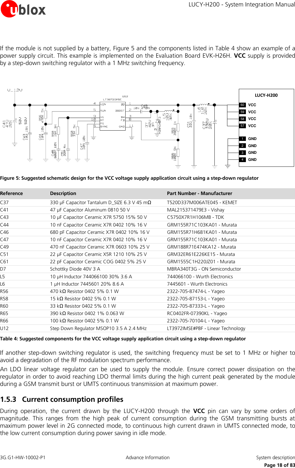
    LUCY-H200 - System Integration Manual 3G.G1-HW-10002-P1  Advance Information  System description      Page 18 of 83  If the module is not supplied by a battery, Figure 5 and the components listed in Table 4 show an example of a power supply circuit. This example is implemented on the Evaluation Board EVK-H26H. VCC supply is provided by a step-down switching regulator with a 1 MHz switching frequency.  LUCY-H20060 VCC59 VCC58 VCC57 VCC1GND2GND3GND4GND Figure 5: Suggested schematic design for the VCC voltage supply application circuit using a step-down regulator  Reference Description Part Number - Manufacturer C37 330 µF Capacitor Tantalum D_SIZE 6.3 V 45 mΩ  T520D337M006ATE045 - KEMET C41 47 µF Capacitor Aluminum 0810 50 V  MAL215371479E3 - Vishay C43 10 µF Capacitor Ceramic X7R 5750 15% 50 V  C5750X7R1H106MB - TDK C44 10 nF Capacitor Ceramic X7R 0402 10% 16 V  GRM155R71C103KA01 - Murata C46 680 pF Capacitor Ceramic X7R 0402 10% 16 V  GRM155R71H681KA01 - Murata C47 10 nF Capacitor Ceramic X7R 0402 10% 16 V  GRM155R71C103KA01 - Murata C49 470 nF Capacitor Ceramic X7R 0603 10% 25 V  GRM188R71E474KA12 - Murata C51 22 µF Capacitor Ceramic X5R 1210 10% 25 V  GRM32ER61E226KE15 - Murata C61 22 pF Capacitor Ceramic COG 0402 5% 25 V  GRM1555C1H220JZ01 - Murata D7 Schottky Diode 40V 3 A MBRA340T3G - ON Semiconductor L5 10 µH Inductor 744066100 30% 3.6 A 744066100 - Wurth Electronics L6 1 µH Inductor 7445601 20% 8.6 A 7445601 - Wurth Electronics R56 470 kΩ Resistor 0402 5% 0.1 W  2322-705-87474-L - Yageo R58 15 kΩ Resistor 0402 5% 0.1 W  2322-705-87153-L - Yageo R60 33 kΩ Resistor 0402 5% 0.1 W  2322-705-87333-L - Yageo R65 390 kΩ Resistor 0402 1% 0.063 W  RC0402FR-07390KL - Yageo R66 100 kΩ Resistor 0402 5% 0.1 W  2322-705-70104-L - Yageo U12 Step Down Regulator MSOP10 3.5 A 2.4 MHz LT3972IMSE#PBF - Linear Technology Table 4: Suggested components for the VCC voltage supply application circuit using a step-down regulator If another step-down switching  regulator  is  used, the  switching frequency  must be set to 1 MHz or higher to avoid a degradation of the RF modulation spectrum performance. An  LDO  linear  voltage  regulator  can  be  used  to  supply  the  module.  Ensure  correct  power  dissipation  on  the regulator in order to avoid reaching LDO thermal limits during the high current peak generated by the module during a GSM transmit burst or UMTS continuous transmission at maximum power. 1.5.3 Current consumption profiles During  operation,  the  current  drawn  by  the  LUCY-H200  through  the  VCC  pin  can  vary  by  some  orders  of magnitude.  This  ranges  from  the  high  peak  of  current  consumption  during  the  GSM  transmitting  bursts  at maximum power level in 2G connected mode, to continuous high current drawn in UMTS connected mode, to the low current consumption during power saving in idle mode.
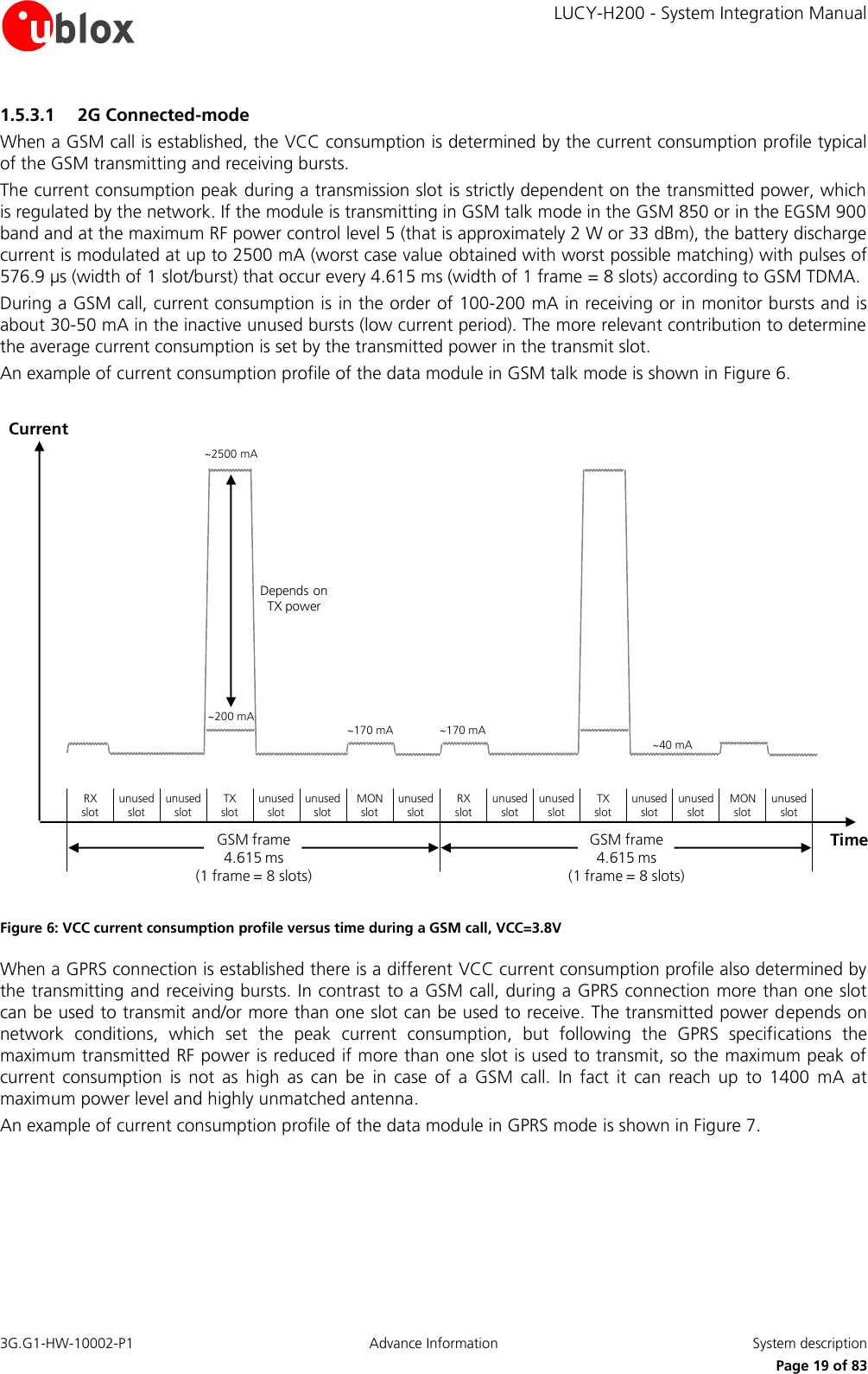
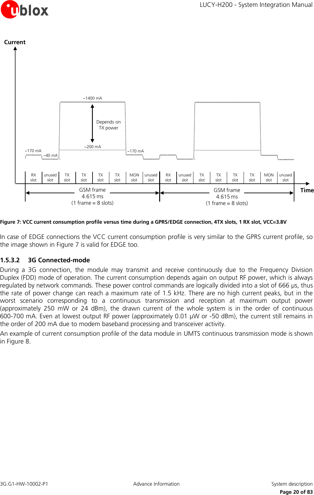
    LUCY-H200 - System Integration Manual 3G.G1-HW-10002-P1  Advance Information  System description      Page 19 of 83 1.5.3.1 2G Connected-mode When a GSM call is established, the VCC consumption is determined by the current consumption profile typical of the GSM transmitting and receiving bursts. The current consumption peak during a transmission slot is strictly dependent on the transmitted power, which is regulated by the network. If the module is transmitting in GSM talk mode in the GSM 850 or in the EGSM 900 band and at the maximum RF power control level 5 (that is approximately 2 W or 33 dBm), the battery discharge current is modulated at up to 2500 mA (worst case value obtained with worst possible matching) with pulses of 576.9 µs (width of 1 slot/burst) that occur every 4.615 ms (width of 1 frame = 8 slots) according to GSM TDMA. During a GSM call, current consumption is in the order of 100-200 mA in receiving or in monitor bursts and is about 30-50 mA in the inactive unused bursts (low current period). The more relevant contribution to determine the average current consumption is set by the transmitted power in the transmit slot. An example of current consumption profile of the data module in GSM talk mode is shown in Figure 6.  TimeRX     slotunused slotunused slotTX     slotunused slotunused slotMON       slotunused slotRX     slotunused slotunused slotTX     slotunused slotunused slotMON   slotunused slotGSM frame             4.615 ms                                       (1 frame = 8 slots)Current~200 mA~40 mA~170 mA~2500 mADepends on TX power~170 mAGSM frame             4.615 ms                                       (1 frame = 8 slots) Figure 6: VCC current consumption profile versus time during a GSM call, VCC=3.8V When a GPRS connection is established there is a different VCC current consumption profile also determined by the transmitting and receiving bursts. In contrast  to a GSM call, during a GPRS connection more than one slot can be used to transmit and/or more than one slot can be used to receive. The transmitted power depends on network  conditions,  which  set  the  peak  current  consumption,  but  following  the  GPRS  specifications  the maximum transmitted RF power is reduced if more than one slot is used to transmit, so the maximum peak of current  consumption  is  not  as  high  as  can  be  in  case  of  a  GSM  call.  In  fact  it  can  reach  up  to  1400  mA  at maximum power level and highly unmatched antenna. An example of current consumption profile of the data module in GPRS mode is shown in Figure 7.
    LUCY-H200 - System Integration Manual 3G.G1-HW-10002-P1  Advance Information  System description      Page 20 of 83 TimeRX       slotunused slotTX       slotTX       slotTX       slotTX        slotMON       slotunused slotRX       slotunused slotTX       slotTX       slotTX       slotTX        slotMON   slotunused slotGSM frame             4.615 ms                                       (1 frame = 8 slots)Current~200 mA~40 mA~170 mA~1400 mADepends on TX power~170 mAGSM frame             4.615 ms                                       (1 frame = 8 slots) Figure 7: VCC current consumption profile versus time during a GPRS/EDGE connection, 4TX slots, 1 RX slot, VCC=3.8V In case of EDGE connections the VCC current consumption profile is very similar to the GPRS current profile, so the image shown in Figure 7 is valid for EDGE too. 1.5.3.2 3G Connected-mode During  a  3G  connection,  the  module  may  transmit  and  receive  continuously  due  to  the  Frequency  Division Duplex (FDD) mode of operation. The current consumption depends again on output RF power, which is always regulated by network commands. These power control commands are logically divided into a slot of 666 µs, thus the rate of power change can reach a maximum rate of 1.5 kHz. There are no high current peaks, but in the worst  scenario  corresponding  to  a  continuous  transmission  and  reception  at  maximum  output  power (approximately  250  mW  or  24  dBm),  the  drawn  current  of  the  whole  system  is  in  the  order  of  continuous 600-700 mA. Even at lowest output RF power (approximately 0.01 µW or -50 dBm), the current still remains in the order of 200 mA due to modem baseband processing and transceiver activity. An example of current consumption profile of the data module in UMTS continuous transmission mode is shown in Figure 8.
    LUCY-H200 - System Integration Manual 3G.G1-HW-10002-P1  Advance Information  System description      Page 21 of 83 Time3G frame             10 ms                                       (1 frame = 15 slots)Current170 mA650 mADepends on TX power1 slot  666 µs Figure 8: VCC current consumption profile versus time during a UMTS connection, VCC=3.8V When a packet data connection is established, the actual current profile depends on the amount of transmitted packets;  there  might  be  some  periods  of  inactivity  between  allocated  slots  where  current  consumption  drops about 100 mA. Alternatively, at higher data rates the transmitted power is likely to increase due to the higher quality signal required by the network to cope with enhanced data speed. 1.5.3.3 Idle-mode By  default  the  module  does  not  automatically  enter  idle-mode  (power-saving  mode)  whenever  possible;  idle mode must be enabled using the appropriate AT command (refer to u-blox 3.5G HSDPA AT Commands Manual [2]). When the data module is registered or attached to a network and a voice or data call is not enabled, the module must periodically monitor the paging channel of the current base station (paging block reception), in accordance to GSM and UMTS system requirements. When the module monitors the paging channel, it wakes up to active mode,  to  enable  the  paging  block  reception.  In  between,  the  module  switches  to  idle-mode  (power-saving mode). This is known as discontinuous reception (DRX). The  module  processor  core  is  activated  during  the  paging  block  reception,  and  automatically  switches  its reference clock frequency from the 32 kHz to the 26 MHz used in active-mode. The time period between two paging block receptions is defined by the network. For example, the time interval between two paging block receptions for 2G operation can be from 470.76 ms (width of 2 GSM multiframes = 2 x 51 GSM frames = 2 x 51 x 4.615 ms) up to 2118.42 ms (width of 9 GSM multiframes = 9 x 51 frames = 9 x 51 x 4.615 ms): this is the paging period parameter, fixed by the base station through broadcast channel sent to all users on the same serving cell. An example of a data module current consumption profile is shown in Figure 9: the module is registered with a 2G network, automatically goes into idle mode and periodically wakes up to active mode to monitor the paging channel for paging block reception
    LUCY-H200 - System Integration Manual 3G.G1-HW-10002-P1  Advance Information  System description      Page 22 of 83 ~150 mA500-700 µA500-700 uA8-10 mA20-22 mA~150 mA0.44-2.09 s~30 msActive Mode EnabledIdle Mode EnabledPLL EnabledRX+DSP EnabledIDLE MODE ACTIVE MODE IDLE MODEIDLE MODE~30 msACTIVE MODECurrentTime Figure 9: Description of the VCC current consumption profile versus time when the module is registered on the GSM network: the module is in idle mode and periodically wakes up to active mode to monitor the paging channel for paging block reception 1.5.4 RTC Supply (V_BCKP) The V_BCKP pin connects the supply for Real Time Clock (RTC) and Power On / Reset internal logic. This supply domain is internally  generated by a  linear regulator integrated in the  power management  unit. The output of this linear  regulator is  always  enabled  when the  main  voltage supply  provided  to  the  module through  VCC  is within the valid operating range, being the module switched-off or powered-on. The RTC provides the time reference (date and time) of the module, also in power-off mode, when the V_BCKP voltage is within its valid range (specified in u-blox LUCY-H200 Data Sheet [1]). The RTC timing is normally used to  set  the  wake-up  interval  during  idle-mode  periods  between  network  paging,  but  is  able  to  provide programmable alarm functions by means of the internal 32.768 kHz clock. The RTC can be supplied from an external back-up battery through the V_BCKP, when the main voltage supply is not provided to the module through VCC. This lets the time reference (date and time) run even when the main supply is not provided to the module. Please consider that the module cannot switch on if a valid voltage is not present on VCC even when RTC is supplied through V_BCKP (meaning that VCC is mandatory to switch-on the module). The  RTC has  very  low power  consumption,  but  is  highly  temperature  dependent.  For  example  at  25°C and  a V_BCKP voltage of 2.0 V the power consumption is approximately 2 µA, whereas at 70°C and an equal voltage the power consumption increases to 5-10 µA.    The  internal  regulator  for  V_BCKP  is  optimized  for  low  leakage  current  and  very  light  loads.  It  is recommended to not use V_BCKP to supply external loads.
    LUCY-H200 - System Integration Manual 3G.G1-HW-10002-P1  Advance Information  System description      Page 23 of 83 If V_BCKP is left unconnected and the module main voltage supply is removed from VCC, the RTC is supplied from the 1 µF buffer capacitor mounted inside the module. However, this capacitor is not able to provide a long buffering time: within 0.5 seconds the voltage on V_BCKP will go below the valid range (1 V min). At this time the internal RTC will stop counting and  the  date and time setting will be lost. This has no impact on wireless connectivity, as all the functionalities of the module do not rely on the date and time setting.   V_BCKP shall be left unconnected if  the  RTC is not required when  the VCC supply is removed. The date and  time  will  not  be  updated  when  VCC  is  disconnected.  If  VCC  is  always  supplied,  then  the  internal regulator will take input from the main supply and there is no need for an external component on V_BCKP.  If RTC is required to run for a time interval of T [seconds] at 25°C when VCC supply is removed, place a capacitor with a nominal capacitance of C [µF] at the V_BCKP pin. Choose the capacitor using the following formula: C [µF] = (Current_Consumption [µA] x T [seconds]) / Voltage_Drop [V] = 2 x T [seconds] The current consumption of the RTC is approximately 2 µA at 25°C, and the voltage drop is equal to 1 V (from the V_BCKP typical value of 2.0 V to the valid range minimum limit of 1.0 V). For example, a 100 µF capacitor (such as the Murata GRM43SR60J107M) can be placed at V_BCKP to provide a long  buffering  time.  This  capacitor  will  hold  V_BCKP  voltage  within  its  valid  range  for  around 50  seconds  at 25°C, after the VCC supply is removed. If a very long buffering time is required, a 70 mF super-capacitor (e.g. Seiko Instruments XH414H-IV01E) can be placed at V_BCKP, with a 4.7 kΩ series resistor to hold the V_BCKP voltage within its valid range for around 10 hours at 25°C, after the  VCC supply is removed. These capacitors will allow the time reference to run during battery disconnection.  2100 µF GRM43SR60J107M70 mFXH414H-IV01E 4.7 kLUCY-H20055 V_BCKP2LUCY-H20055 V_BCKP Figure 10: Real time clock supply (V_BCKP) application circuits using a 100 µF capacitor to let the RTC run for ~50 seconds at 25°C or using a 70 mF capacitor to let the RTC run for ~10 hours at 25°C when the VCC supply is removed  1.5.5 Interface supply (V_INT) The same voltage domain used internally to supply the digital interfaces is also available  at the board-to-board connector on pin V_INT. The internal regulator is a switching step down converter: it is directly supplied from VCC and output voltage is set to 1.8 V (typical). It operates in Pulse Width Modulation (PWM) for high output current mode but automatically switches to Pulse Frequency Modulation (PFM) at low output loads for greater efficiency, e.g. when the module is in idle mode between paging periods.
    LUCY-H200 - System Integration Manual 3G.G1-HW-10002-P1  Advance Information  System description      Page 24 of 83 Being  the  supply  of  internal  digital  circuits  (see  Figure  3),  V_INT  is  not  suited  to  directly  supply  any  sensitive analog  circuit:  the  voltage  ripple  may  range  from  20  mV  during  active  mode  (PWM),  to  70  mV  in  idle  mode (PFM), in addition to few tens of mV of short overshoot / undershot due to dynamic response of transient loads.   V_INT  can  be  used  to  supply  external  digital  circuits  operating  at  the  same  voltage  level  as  the  digital interface  pins,  i.e.  1.8  V  (typical).  It  is  not  recommended  to  supply  analog  circuitry  without  adequate filtering for digital noise.   Don’t apply loads which might exceed the limit for maximum available current from V_INT supply, as this can cause malfunctions to internal circuitry supplies to the same domain.   V_INT can only be used as an output; don’t connect any external regulator on V_INT. If not used this pin should be left unconnected.  Typical usage  of  V_INT  is to  connect a pull-up  resistor  for  the  DDC  (I2C) interface.  See  section  1.11 for  more details.
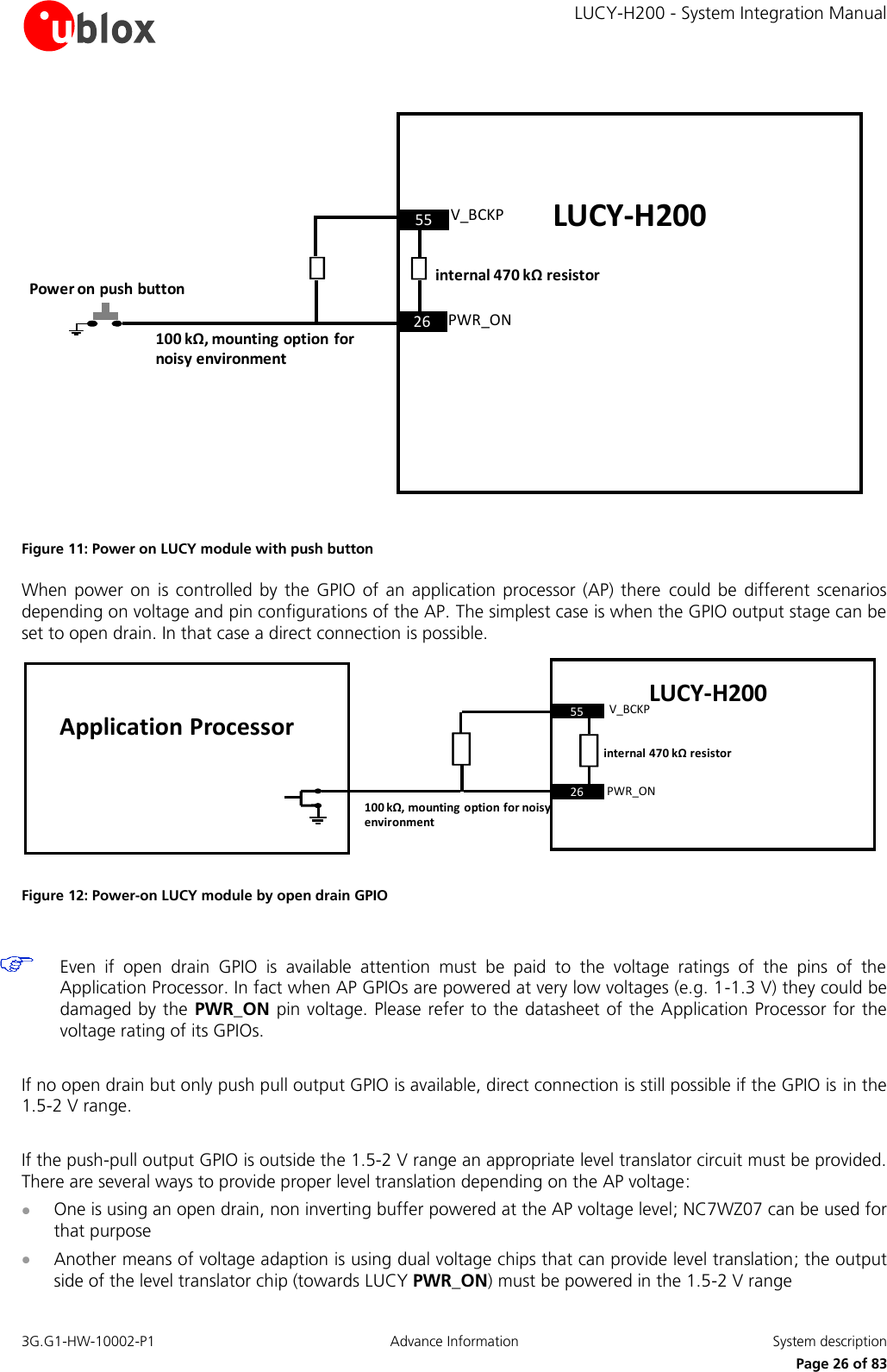
    LUCY-H200 - System Integration Manual 3G.G1-HW-10002-P1  Advance Information  System description      Page 25 of 83 1.6 System functions 1.6.1 Module power on When supply is connected to the VCC pin, the voltage supervision circuit controls the subsequent activation of the power up state machines. The module power-on sequence is initiated in one of 3 ways:  Falling edge on the PWR_ON signal  RTC alarm  Detection on pin VUSB_DET of a valid VUSB voltage (typical 5V) for USB detection  Name Description Remarks  PWR_ON Power-on input PWR_ON pin has an internal pull-up resistor to V_BCKP. Nevertheless provide space for mounting an external pull up resistor on the application board in case of noisy environment, where an external pull-up is required Table 5: Power-on pin  1.6.1.1 Falling edge on the PWR_ON The module power-on sequence starts when a low level is forced on the PWR_ON signal. The electrical characteristics of the PWR_ON input pin are different from the other digital I/O interfaces: the high and  the  low  logic  levels  have  different  operating  ranges  and  the  pin  is  tolerant  of  voltages  only  up  to  the V_BCKP voltage. The nominal V_BCKP pin voltage is 2 V; the detailed electrical characteristics are described in the LUCY-H200 Data Sheet [1].    The PWR_ON pin is pulled up to V_BCKP through an internal 470 kΩ resistor. To avoid floating in a noisy environment: a pull up resistor to V_BCKP supply can be added on the application board at least as a not mounting option.   The  boot time  is  around  1  second  when  the  falling  edge  on the  PWR_ON  pin  is  used  to  power  on the module.  Note that the module can be switched-on by a falling edge on the PWR_ON pin. Once the module has turned on moving the PWR_ON pin has no effect. On the other hand it makes no sense to keep this pin low when the module is turned on as it would source some unnecessary µA. Following are some typical examples of turning the module on. The simplest way to turn on the module is to use a push button connected to ground.
    LUCY-H200 - System Integration Manual 3G.G1-HW-10002-P1  Advance Information  System description      Page 26 of 83 100 kΩ, mounting option for noisy environment55 V_BCKPPWR_ONLUCY-H200internal 470 kΩresistorPower on push button26 Figure 11: Power on LUCY module with push button When  power  on is  controlled  by  the GPIO  of  an  application processor (AP)  there  could  be  different  scenarios depending on voltage and pin configurations of the AP. The simplest case is when the GPIO output stage can be set to open drain. In that case a direct connection is possible. 100 kΩ, mounting option for noisy environment5526V_BCKPPWR_ONLUCY-H200internal 470 kΩresistorApplication Processor Figure 12: Power-on LUCY module by open drain GPIO    Even  if  open  drain  GPIO  is  available  attention  must  be  paid  to  the  voltage  ratings  of  the  pins  of  the Application Processor. In fact when AP GPIOs are powered at very low voltages (e.g. 1-1.3 V) they could be damaged by the PWR_ON pin voltage. Please refer to the datasheet of the Application Processor for the voltage rating of its GPIOs.  If no open drain but only push pull output GPIO is available, direct connection is still possible if the GPIO is in the 1.5-2 V range.  If the push-pull output GPIO is outside the 1.5-2 V range an appropriate level translator circuit must be provided. There are several ways to provide proper level translation depending on the AP voltage:  One is using an open drain, non inverting buffer powered at the AP voltage level; NC7WZ07 can be used for that purpose  Another means of voltage adaption is using dual voltage chips that can provide level translation; the output side of the level translator chip (towards LUCY PWR_ON) must be powered in the 1.5-2 V range
    LUCY-H200 - System Integration Manual 3G.G1-HW-10002-P1  Advance Information  System description      Page 27 of 83 Remember to fix the unused inputs of buffers or voltage translator chips with more ports than required to GND or to power in order to prevent increase in power consumption due to high impedance floating inputs. 1.6.1.2 Real Time Clock (RTC) alarm Power on If a valid voltage is maintained at the VCC pin, the module can be switched-on by the RTC alarm when the RTC system  reaches  a  pre-programmed  scheduled  time.  The  RTC  system  will  then  initiate  the  boot  sequence  by indicating to the power  management  unit to turn on  power.  Also included in this  setup is an interrupt  signal from the RTC block to indicate to the baseband processor, that an RTC event has occurred.    The boot time is around 1 second when the power on of the module is caused by RTC alarm. 1.6.1.3 Detection on pin VUSB_DET of a valid VUSB voltage If a valid VUSB voltage is detected on the VUSB_DET pin, the module turns on. Please refer to the LUCY-H200 Data Sheet [1] for the VUSB range that must be applied to VUSB_DET pin. When the power on cause is a valid VUSB  voltage,  USB  block  is  turned  on  and  UART0  is  disabled.  Once  the  module  is  powered,  if  voltage  at VUSB_DET  goes  outside  of  the  VUSB  range,  UART0  is  re-enabled.  The  line  that  triggers  power  on  at VUSB_DET pin must have less than 100 Ω impedance.    When voltage at VUSB_DET pin is in the VUSB range the module does not enter idle state even if has been enabled  by  the  appropriate  AT  command  (for  more  details  please  refer  to  u-blox  3.5G  HSDPA  AT commands manual [2]).   The  boot time  is  around  3  seconds  when  the  power  on  is  caused  by  a  USB  range  voltage  (4.3  V-5.3  V, typically 5 V) at VUSB_DET pin.  1.6.2 Module power off The LUCY-H200 module can be switched off by one of the following switch-off events:  Via AT command AT+CPWROFF (more details in u-blox 3.5G HSDPA AT Commands Manual [2])  An under-voltage shutdown will be done if VCC falls below the valid operating limit  After  a  switch-off  event has been triggered,  the digital pins are  locked in  tri-state  by  the module.  All  internal voltage regulators, except the RTC supply, are turned off in a defined power-off sequence. 1.6.3 Module reset Reset the module using RESET_N: this performs an external or hardware reset. When the RESET_N pin is driven low, an asynchronous reset of the entire module - except for the RTC - is triggered, and the device is initialized into a defined reset state.  Name Description Remarks RESET_N External reset input Internal pull-up Table 6: Reset pin The electrical characteristics of RESET_N are different from the other digital I/O interfaces. The detailed electrical characteristics are described in the LUCY-H200 Data Sheet [1]. RESET_N is pulled high by an integrated pull-up resistor. Therefore an external pull-up should be not required on the application board. An internal circuit pulls the level to 2.0 V. Forcing RESET_N low for at least 50 ms will cause an external reset of the module. When RESET_N is released from the low level, the module automatically starts its power-on reset sequence.
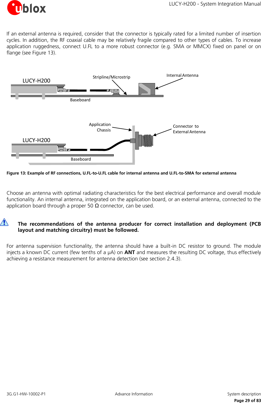
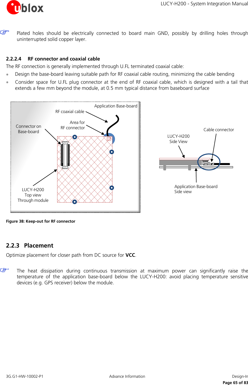
    LUCY-H200 - System Integration Manual 3G.G1-HW-10002-P1  Advance Information  System description      Page 28 of 83 If RESET_N is connected to an external device (e.g. an application processor on an application board) an open drain output can be directly connected without any external pull-up. Otherwise, use a push-pull output. Make sure to fix the proper level on RESET_N in all possible scenarios, to avoid unwanted reset of the module. The reset state of all input-output pins is reported in the pin description table in the LUCY-H200 Data Sheet [1]. 1.7 RF connection The  interface  for  RF  signal  (ANT)  is  available  via  the  Hirose  U.FL-SMT-R  or  equivalent  sub-miniature  coaxial connector.  The  ANT  interface  has  a  nominal  impedance  of  50  Ω,  and  must  be  connected  to  the  antenna through a 50 Ω transmission line to allow transmission and reception of radio frequency (RF) signals in the GSM and UMTS operating bands.  Name Description Remarks ANT RF antenna Zo = 50   nominal characteristic impedance. Hirose U.FL-SMT-R receptacle connector. Table 7: Antenna pin The RF receptacle implemented on  the  LUCY-H200  for  ANT  requires a suitable mated  RF plug from the  same connector series. Due to its wide usage in the industry, several manufacturers offer compatible equivalents. The  board-to-board connector  stacked  mated height  also  limits the  selection  of  the  RF plug.  Nevertheless the nominal 3 mm height of the board-to-board connector effectively allows the usage of all U.FL compatible plugs available on the market. Table  8  lists  some  RF  connector  plugs  that  fit  LUCY-H200,  based  on  the  declaration  of  the  respective manufacturers. Only the Hirose has been qualified for the LUCY-H200 module, contact other producers to verify compatibility.  Manufacturer Series Remarks Hirose U.FL® Ultra Small Surface Mount Coaxial Connector Recommended I-PEX MHF® Micro Coaxial Connector  Tyco UMCC® Ultra-Miniature Coax Connector  Amphenol RF AMC® Amphenol Micro Coaxial  LTI (Lighthorse Technologies, Inc) IPX ultra micro-miniature RF connector  Table 8: U.FL compatible plug connector Typically the RF plug is available as a cable assembly: several kinds are available and the user should select the cable assembly best suited to the application. The key characteristics are:   RF plug type: select U.FL or equivalent  Cable thickness: typically from 0.8 mm to 1.37 mm  Cable length: standard length is typically 100 mm or 200 mm, custom lengths may be available on request  RF  connector  on  other  cable  side: for  example  another  U.FL  (for  board-to-board  connection)  or  SMA  (for panel mounting)    The LUCY-H200 module is calibrated at the on-board U.FL receptacle: select thicker and shorter cables to minimize insertion loss.  For  applications  requiring  an  internal  integrated  SMT  antenna,  it  is  suggested  to  use  a  U-FL-to-U.FL  cable  to provide RF path from the LUCY-H200 to PCB stripline or microstrip connected to antenna pads (see Figure 13). Take  care  that  the  PCB-to-RF-cable  transition,  stripline  and  antenna  pads  must  be  optimized  for  50  Ω characteristic impedance.
    LUCY-H200 - System Integration Manual 3G.G1-HW-10002-P1  Advance Information  System description      Page 29 of 83 If an external antenna is required, consider that the connector is typically rated for a limited number of insertion cycles. In addition, the RF coaxial cable may be relatively fragile compared to other types of cables. To increase application  ruggedness,  connect  U.FL to  a  more  robust connector  (e.g.  SMA  or  MMCX)  fixed  on  panel  or  on flange (see Figure 13).  LUCY-H200BaseboardStripline/Microstrip Internal AntennaBaseboardApplication  Chassis Connector  to External AntennaLUCY-H200 Figure 13: Example of RF connections, U.FL-to-U.FL cable for internal antenna and U.FL-to-SMA for external antenna  Choose an antenna with optimal radiating characteristics for the best electrical performance and overall module functionality. An internal antenna, integrated on the application board, or an external antenna, connected to the application board through a proper 50 Ω connector, can be used.   The  recommendations  of  the  antenna  producer  for  correct  installation  and  deployment  (PCB layout and matching circuitry) must be followed.  For  antenna  supervision  functionality,  the  antenna  should  have  a  built-in  DC  resistor  to  ground.  The  module injects a known DC current (few tenths of a µA) on ANT and measures the resulting DC voltage, thus effectively achieving a resistance measurement for antenna detection (see section 2.4.3).
    LUCY-H200 - System Integration Manual 3G.G1-HW-10002-P1  Advance Information  System description      Page 30 of 83 1.8 Antenna supervisor  Antenna detection is internally performed by the module via ANT. The RF port is DC coupled to the ADC unit in the baseband  chip.  The module measures  the DC voltage at  ANT,  in  the  range  of  0  to 2  V. Additionally,  the module can inject a known DC current (~ 100 µA) on ANT and measures the resulting DC voltage. LUCY-H200ANTADCCurrent SourceRF ChokeDC BlockingFront-End RF Module Figure 14: Antenna Supervisor internal circuit If  the  DC  voltage  is  present  on  ANT,  or  a  DC  connection  to  a  known  resistor  at  the  radiating  element  is implemented, the module will be able to check the connection to the Antenna element. Refer to the u-blox 3.5G HSDPA AT Commands Manual [2] for more details on how to access this feature.  1.9 SIM interface An SIM card interface is provided on the board-to-board pins of the module: the high-speed SIM/ME interface is implemented as well as automatic detection of the required SIM supporting voltage. Both 1.8 V  and  3  V SIM  types are supported: activation  and deactivation  with  automatic voltage  switch  from 1.8V  to  3  V  is  implemented,  according  to  ISO-IEC  7816-3  specifications.  The  SIM  driver  supports  the  PPS (Protocol and Parameter Selection) procedure for baud-rate selection, according to the values determined by the SIM Card. Table 9 describes the board to board pins related to the SIM interface: Name Description Remarks VSIM SIM supply 1.80 V typical or 2.90 V typical  automatically generated by the module SIM_CLK SIM clock 3.25 MHz clock frequency SIM_IO SIM data Open drain, internal 4.7 kΩ pull-up resistor to VSIM SIM_RST SIM reset  Table 9: SIM Interface pins Figure 15 shows the minimal circuit connecting the LUCY module and the SIM card.
    LUCY-H200 - System Integration Manual 3G.G1-HW-10002-P1  Advance Information  System description      Page 31 of 83 LUCY-H20034333235SIM CARD HOLDERCCVCC (C1)CCVPP (C6)CCIO (C7)CCCLK (C3)CCRST (C2)GND (C5)5VSIM6SIM_IO7SIM_CLK8SIM_RST Figure 15: SIM interface application circuit When connecting the module to SIM connector perform the following steps on the application board:  Bypass digital noise via a 100 nF capacitor (e.g. Murata GRM155R71C104K) on the SIM supply (VSIM)  To prevent RF coupling in case the module RF antenna is placed closer than 10 - 30 cm from the SIM card holder, connect a bypass capacitor  of about 22 pF to 47 pF (e.g. Murata GRM1555C1H470J) at each SIM signal (SIM_CLK, SIM_IO, SIM_RST) to ground near the SIM connector  Mount very low capacitance ESD protection (e.g. Infineon ESD8V0L2B-03L or AVX USB0002RP) near the SIM card connector  Limit capacitance on each SIM signal to match the SIM specifications: always route the connections as short as possible 1.9.1 (U)SIM functionality The following SIM services are supported:  Abbreviated Dialing Numbers (ADN)  Fixed Dialing Numbers (FDN)  Last Dialed Numbers (LDN)  Service Dialing Numbers (SDN)  USIM Application Toolkit (USAT) R99 is supported.  1.10 Asynchronous serial interface (UART) The  UART  interface  is  an  8-wire  unbalanced  asynchronous  serial  interface  that  provides  an  AT  commands interface,  GPRS  data  and  CSD  data,  software  upgrades.  The  LUCY  module  implements  two  UART  interfaces: UART0 (8-wire interface) and UART1 (4-wire interface). The UART0 interface provides RS-232 functionality conforming to the ITU-T V.24 Recommendation (more details available in ITU Recommendation [3]), with CMOS compatible signal levels: 0 V for low data bit or ON state, and 1.8  V  for  high  data  bit  or  OFF  state.  Two  different  external  voltage  translators  (Maxim  MAX3237E  and  On Semiconductor NLSX3018MUTAG) could be used to provide full RS-232 (8 lines) compatible signal levels. The On Semiconductor chip provides the translation from 1.8 V to 3.3 V, while the Maxim chip provides the necessary RS-232 compatible signal towards the external connector. If an UART interface with only 4 lines is needed, the Maxim 13234E  voltage level translator can be used. This chip translates the voltage levels from 1.8 V (modem side) to the RS-232 standard. For detailed electrical characteristics refer to the LUCY-H200 Data Sheet [1].
    LUCY-H200 - System Integration Manual 3G.G1-HW-10002-P1  Advance Information  System description      Page 32 of 83 The LUCY-H200 modules is designed to operate as a UMTS/HSDPA modem, which represents the data circuit-terminating  equipment  (DCE)  as  described  by  the  ITU-T  V.24  Recommendation  [3].  A  customer  application processor connected to the module through the UART interface represents the data terminal equipment (DTE).    Take  care  to  provide  the  needed  accessibility  (by  means  of  test  points,  connector  etc.)  to  UART0_TX, UART0_RX and PWR_ON pins in order to re-flash/update the LUCY module even if it is not planned to use UART0.   The signal names of the LUCY-H200 UART interface are conform to ITU-T V.24 Recommendation [3]. The UART interface includes the following lines:  Name Description Remarks DSR Data set ready Module output, functionality of ITU-T V.24 Circuit 107 (Data set ready) RI Ring Indicator Module output, functionality of ITU-T V.24 Circuit 125 (Calling indicator) DCD Data carrier detect Module output, functionality of ITU-T V.24 Circuit 109 (Data channel received line signal detector) DTR Data terminal ready Module input, functionality of ITU-T V.24 Circuit 108/2 (Data terminal ready) Internal active pull-up to 1.8 V enabled. RTS Ready to send Module hardware flow control input, functionality of ITU-T V.24 Circuit 105 (Request to send) Internal active pull-up to 1.8 V enabled. CTS Clear to send Module hardware flow control output, functionality of ITU-T V.24 Circuit 106 (Ready for sending) TxD Transmitted data Module data input, functionality of ITU-T V.24 Circuit 103 (Transmitted data) Internal active pull-up to 1.8 V enabled. RxD Received data Module data output, functionality of ITU-T V.24 Circuit 104 (Received data)  1.10.1 UART features UART interface(s) are controlled and operated with:  AT commands according to 3GPP TS 27.007 [4]  AT commands according to 3GPP TS 27.005 [5]  AT commands according to 3GPP TS 27.010 [6]  u-blox AT commands All flow control handshakes are supported by the UART interface and can be set by appropriate AT commands (see  u-blox  3.5G  HSDPA  AT  Commands  Manual [2]):  hardware  flow  control  (RTS/CTS),  software  flow  control (XON/XOFF), or none flow control.    Hardware flow control is default.   For  the  complete  list  of  supported  AT  commands  and  their  syntax  refer  to  the  u-blox  3.5G  HSDPA  AT Commands Manual [2].  The following baud rates can be configured using AT commands:  2400 b/s  4800 b/s  9600 b/s
    LUCY-H200 - System Integration Manual 3G.G1-HW-10002-P1 Advance Information  System description      Page 33 of 83  19200 b/s  38400 b/s  57600 b/s  115200 b/s  230400 b/s  460800 b/s  The frame format can be:  8N1 (8 data bits, No parity, 1 stop bit)  8E1 (8 data bits, even parity, 1 stop bit)  8O1 (8 data bits, odd parity, 1 stop bit)  8N2 (8 data bits, No parity, 2 stop bits) The default frame configuration with fixed baud rate is 8N1, described in the Figure 16.  D0 D1 D2 D3 D4 D5 D6 D7Start of 1-BytetransferStart Bit(Always 0)Possible Start ofnext transferStop Bit(Always 1)tbit = 1/(Baudrate)Normal Transfer, 8N1 Figure 16: UART default frame format (8N1) description  1.10.2 UART0 signal behavior See Table 2 for a description of operating modes and states referred to in this section. By default the RxD and the TxD lines are set to OFF state at UART initialization, following the boot sequence when the module is switched on. The module holds RxD and TxD in OFF state until data is either transmitted or received by the module: an active pull-up is enabled inside the module on the TxD input. The  hardware  flow  control  output  (CTS  line)  indicates  when  the  module  is  in  active  mode  and  the  UART interface is enabled: the module drives the CTS line to the ON state or to the OFF state when it is either prepared or not prepared to accept data from the external device (DTE). After the boot sequence the CTS line is set to ON state at UART initialization, when the module is in active-mode and ready to operate. By default the module automatically enters idle-mode (power saving) unless this mode has been disabled using an AT command (see u-blox 3.5G HSDPA AT Commands Manual [2]). Data sent by the DTE can be lost if hardware flow-control is not enabled. The module periodically wakes up from idle-mode to active-mode to be synchronized with network activity. Idle-mode time is fixed by network parameters and can be up to ~2.1 s. When the module wakes up to active-mode, the UART interface is enabled: the CTS line is switched to ON state and is held in this state for a minimum of ~11 ms. The behavior of hardware flow-control output (CTS line) during normal module operations (idle mode and active mode) is illustrated in Figure 17.
    LUCY-H200 - System Integration Manual 3G.G1-HW-10002-P1  Advance Information  System description      Page 34 of 83 The  time  delay  for  the  module  to  go  from  active-mode  to  idle-mode  depends  (in  addition  to  dependency  on network parameters) on the timeout from the last data received at the serial port. This timeout is configurable by the AT+UPSV command, between 40 GSM frames (~184 ms) and 65000 GSM frames (~300 s). Default value is 2000 GSM frames (~9.2 s).   Figure 17: CTS behavior during normal module operation: the CTS line indicates when the module is able (CTS = ON) or not able (CTS = OFF) to accept data from the DTE and communicate through the UART interface The hardware flow control input (RTS line) is set by default to OFF state at UART initialization at the end of the boot sequence, after the module switches on. The RTS line is then held by the module in OFF state if hardware flow- control is not enabled by the DTE. An active pull-up is enabled inside the module on the RTS input. The module drives the DSR line to indicate whether it is ready to operate or not. After the module switches on, DSR line switches from ON state to OFF state as shown in Figure 18. During the  Boot process of the module, DSR is forced to OFF, until the module is not ready to operate. It is switched to ON state when the module is ready to operate. The time Tswitch depends on the duration of the boot process, and is in the range of ~1 s.   Figure 18: DSR behavior at power-on The  DTR  line  is set  by  default to  OFF  state at  UART  initialization,  at  the  end  of  the boot  sequence, after  the module switch on. The DTR line is then held by the module in the OFF state if the line is not  activated by the DTE. An active pull-up is enabled inside the module on the DTR input. The RI and DCD lines are set by default to OFF state at UART initialization, at the end of the boot sequence. The RI line is then held by the module in OFF state until an incoming call or SMS is received. The DCD line is held in OFF state until a data call is accepted. During an incoming call the RI line is switched from OFF state to ON state with a 4:1 duty cycle and a 5 s period (ON for  1  s, OFF  for  4  s, see  Figure  19),  until the  DTE attached to the  module sends  the  ATA  string and  the module accepts the incoming data call. The RING string sent by the module (DCE) to the serial port at constant time intervals is not correlated with the switch of the RI line to the ON state. When the data call is accepted, the module is set to ON state and the serial line DCD sends the CONNECT<communication baudrate> to the DTE. DTE sends data through the DCE and the GSM network to the remote DCE-DTE system and data communication can be performed as for outgoing data calls.  Tswitch0DSR ONDSR OFFPower-on0.024 time [s]Tswitch0DSR ONDSR OFFPower-on0.024 time [s]time [s] CTS ON CTS OFF max ~2.1 s UART disabled min ~11 ms UART enabled ~9.2 s (default) UART enabled Data input time [s] CTS ON CTS OFF max ~2.1 s UART disabled min ~11 ms UART enabled ~9.2 s (default) UART enabled
    LUCY-H200 - System Integration Manual 3G.G1-HW-10002-P1  Advance Information  System description      Page 35 of 83  Figure 19: RI behavior during incoming call The RI line is used to notify an SMS arrival. When the SMS arrives, the RI line switches from OFF to ON for 1 s (see Figure 20).  Figure 20: RI behavior at SMS arrival 1.10.3 Connecting UART0 on application boards - Full RS-232 Functionality For complete RS-232 functionality conforming to ITU Recommendation [3] in DTE/DCE serial communication, the complete UART0 interface of the module (DCE) must be connected to the DTE as described in Figure 21.  LUCY-H200(DCE)Application Processor(DTE)4847TxD_0RxD_05049RTS_0CTS_052464551 DTR_0DSR_0RI_0DCD_0TxDRxDRTSCTSDTRDSRRIDCD Figure 21: Interface application circuit with complete V.24 link in DTE/DCE serial communication SMS arrives time [s] 0 RI ON RI OFF 1s SMS  time [s] 0 RI ON RI OFF 1s 1stime [s]151050RI ONRI OFFCall incomes1stime [s]151050RI ONRI OFFCall incomes
    LUCY-H200 - System Integration Manual 3G.G1-HW-10002-P1  Advance Information  System description      Page 36 of 83 1.10.3.1 Connecting UART0 on application boards - TxD, RxD, RTS and CTS lines only (not using the complete V.24 link) If only the TxD, RxD, RTS and CTS lines are desired, it is possible to use the UART1 serial interface, otherwise follow the application circuit described in Figure 22. HW flow-control is used. The module wakes up from default idle-mode to active-mode when data is received at the UART interface, since the HW flow control is enabled by default in the module.  Connect  on  the  application  board  the  DSR  output  line  to  the  module  DTR  input  line,  since  the  module requires DTR active (low electrical level) and DSR is active (low electrical level) once the module is switched on and the UART0 interface is enabled  Leave DCD and RI lines of the module unconnected and floating  LUCY-H200(DCE)Application Processor(DTE)4847TxD_0RxD_05049RTS_0CTS_052464551 DTR_0DSR_0RI_0DCD_0TxDRxDRTSCTSDTRDSRRIDCD Figure 22: UART0 interface application circuit with partial V.24 link (4-wire) in the DTE/DCE serial communication  1.10.3.2 Connecting TxD and RxD lines only (not complete V24 link)  Follow the application circuit described in Figure 23. HW flow control is not used. The module doesn’t wake up from idle-mode to active-mode when data is received at the UART interface. Since HW flow control is by default enabled in the module, data delivered by the DTE can be lost. The module cannot be woken-up in this case, and for this reason this configuration is not recommended.  Connect on the application circuit the module the CTS output line to the module RTS input line, since the module requires RTS active (low electrical level) and CTS is active (low electrical level) when the module is in active mode and the UART interface is enabled  Connect on the application circuit the module the DSR output line to the module DTR input line, since the module requires DTR active (low electrical level) and DSR is active (low electrical level) once the module is switched on and the UART interface is enabled  DCD and RI lines of the module can be left unconnected and floating Also in this configuration the UART interface can be used as AT commands interface, for GPRS data and CSD data communication and for software upgrades, but without the HW flow  control, data delivered by the DTE can be lost.
    LUCY-H200 - System Integration Manual 3G.G1-HW-10002-P1  Advance Information  System description      Page 37 of 83 LUCY-H200(DCE)Application Processor(DTE)4847TxD_0RxD_05049RTS_0CTS_052464551 DTR_0DSR_0RI_0DCD_0TxDRxDRTSCTSDTRDSRRIDCD Figure 23: UART interface application circuit with partial V.24 link (2-wire) in the DTE/DCE serial communication   On an application board, it is highly recommended to provide direct access to  RxD_0 and TxD_0 lines of the  module  (in  addition  to  access  to  these  lines  from  an  application  processor).  This  enables  a  direct connection of PC (or similar) to the module for execution of Firmware upgrade over the UART. Provide as well access to PWR_ON line in order to flash the module.  1.10.4 UART1 serial port UART1 also provides RTS and CTS lines for HW handshaking. For their use please refer to UART0 RTS and CTS connection.    It is not possible to Flash the module through UART1, so provide appropriate access to UART0 RXD, UART0 TXD, and PWR_ON lines on the application board.
    LUCY-H200 - System Integration Manual 3G.G1-HW-10002-P1  Advance Information  System description      Page 38 of 83  1.10.5 MUX Protocol (3GPP 27.010) The module has a software layer with MUX functionality complaint with 3GPP 27.010 [8]. This is a data link protocol (layer 2 of OSI model) using HDLC-like framing and  operates between the module (DCE)  and  the  application  processor  (DTE).  The  protocol  allows  simultaneous  sessions  over  the  UART.  Each session consists of a stream of  bytes transferring various kinds of data like SMS, CBS, GPRS, AT commands in general. This permits, for example, SMS to be transferred to the DTE when a data connection is in progress. The following virtual channels are defined:  Channel 0: control channel  Channel 1 – 5: AT commands /data connection  Channel 6: GPS tunnelling  1.11 DDC (I2C) interface 1.11.1 Overview An I2C compatible Display Data Channel (DDC) interface for serial communication is implemented. This interface is intended exclusively to access u-blox GPS receivers.  Name Description Remarks SCL I2C bus clock line Open drain. External pull-up required. SDA I2C bus data line Open drain. External pull-up required. Table 10: DDC pins  To be compliant to the I2C bus specifications, the module bus interface pads are open drain output and pull up resistors  must  be  used.  Since  the  pull-up  resistors  are  not  mounted  on  the  module,  they  must  be  mounted externally. Resistor values must conform to the I2C bus specifications [7]. If the LUCY-H200 module is connected through the DDC bus to a single u-blox GPS receiver only (only one device is connected on the DDC bus), use a pull-up  resistor  of  4.7  k .  Pull-ups must  be  connected  to  a  supply voltage  of  1.8  V  (typical),  since  this  is  the voltage domain of the DDC pins. VINT voltage domain can be used to provide 1.8 V for the pull-ups (for detailed electrical characteristics see the LUCY-H200 Data Sheet [1]). DDC Slave-mode operation is not supported, the module can act as master only. Two lines, serial data (SDA) and serial clock (SCL), carry information on the bus. SCL is used to synchronize data transfers, and SDA is the data line. Since both lines are open drain outputs, the DDC devices can only drive them low or leave  them open. The pull-up resistor  pulls the  line  up to the  supply  rail if  no DDC  device  is  pulling it down to GND. If the pull-ups are missing, SCL and SDA lines are undefined and the DDC bus will not work. The signal shape is defined by the values of the pull-up resistors and the bus capacitance. Long wires on the bus will increase  the capacitance. If  the  bus capacitance  is  increased,  use  pull-up resistors  with nominal  resistance value lower than 4.7 k , to match the I2C bus specifications regarding rise and fall times of the signals [7].    Capacitance  must  be  limited  on  the  bus  to  match  the  I2C  specifications:  route  connections  as  short  as possible.   If the pins are not used as DDC bus interface, they can be left unconnected.
    LUCY-H200 - System Integration Manual 3G.G1-HW-10002-P1  Advance Information  System description      Page 39 of 83 1.11.2 DDC application circuit The SDA and SCL lines can be used only to connect the LUCY module to a u-blox GPS module: LUCY DDC (I2C) interface is enabled by the +UGPS AT command only. GPIO2 is automatically driven as output by the +UGPS AT command to switch-on or switch-off the u-blox GPS module, connecting GPIO2 to the active-high enable pin (or the active-low shutdown pin) of the voltage regulator that supplies the u-blox GPS module on the application board. The application circuit for SDA, SCL and GPIO2 is illustrated in Figure 24.   LUCY-H2001.8 V u-blox GPS receiverSDASCL1312SDASCLR1R11.8 VVCC 53 GPIO2OUT SHDNnLDO1.8 V1253 Figure 24: DDC Application circuit for 1.8V u-blox GPS receivers. Name Suggested Value R1 4.7 kΩ Table 11 - Component for DDC application circuit The application circuit depicted in Figure 24 is valid only for the 1.8 V u-blox GPS receivers’ family. LUCY VINT can be used for 1.8 V. If a 3 V u-blox GPS receiver is used, SDA and SCL lines can be simply pulled up to 3 V as shown in Figure 25 since LUCY pins are 3 V tolerant. If a 3 V GPS receiver is used, for future compatibility with the next generation of u-blox UMTS modules, a level translating solution can be placed as a non-mounting option bypassed by zero Ω resistors. For example, Texas Instruments PCA9306 bidirectional I2C voltage level translator can be used as a not mounting option.
    LUCY-H200 - System Integration Manual 3G.G1-HW-10002-P1  Advance Information  System description      Page 40 of 83 LUCY-H2003V u-blox GPS receiverSDASCL1312SDASCLR1R13 VVCC 53 GPIO2OUT SHDNnLDO3 V1253 Figure 25: Application circuit for 3V u-blox GPS receivers.  1.12 SPI interface SPI is a master-slave protocol: the LUCY module natively runs as an SPI slave, e.g. it accepts AT commands on its SPI interface. Any LUCY module can be commanded via AT commands to become an SPI master device. Then, always via AT commands, an embedded program can run on an LUCY module so that the data flow from the AT port is redirected on the SPI interface and vice versa.  The SPI-compatible synchronous serial interface cannot be used for SW download.  The SPI interface includes two signals to transmit and receive data (one is the MOSI master output / slave input data, the other is the MISO master input / slave output data) and a clock signal (SCLK0) generated by the master. The directions of these lines are inverted if the LUCY module runs as an SPI slave or as an SPI master device:  MOSI signal is an output for the LUCY module if it runs as SPI master or is an input if it runs as SPI slave  MISO signal is an input for the LUCY module if it runs as SPI master or is an output if it runs as SPI slave  SCLK0 signal is an output for the LUCY module if it runs as SPI master or is an input if it runs as SPI slave  On the LUCY module, the standard 3-wire SPI interface implements, together with the two handshake signals SPI_MRDY and SPI_SRDY, the 5-wire Inter Processor Communication (IPC) interface. The  purpose  of  the  IPC  interface  is  to  achieve  high  speed  communication  (up  to  12  Mb/s)  between  two processors following the same IPC specifications: the LUCY baseband processor and an external processor. This  interface  is  suggested  for  high  speed  UMTS/HSDPA  communications  and  could  be  necessary  to communicate with an Application Processor which is not equipped with a USB interface.  In the LUCY IPC interface, the SPI interface on the modem side is running in slave mode and the SPI interface on the application processor is running in master mode, so this is the direction of the SPI signals in the IPC interface:  MOSI signal is an input for the LUCY module in the IPC interface  MISO signal is an output for the LUCY module in the IPC interface  SCLK0 signal is an input for the LUCY module in the IPC interface
    LUCY-H200 - System Integration Manual 3G.G1-HW-10002-P1  Advance Information  System description      Page 41 of 83  The function of the  SPI_MRDY and SPI_SRDY signals is twofold. For transmitting data the signal indicates to the  data  receiver  that  data  is  available  to  be  transmitted.  For  reception  of  data  the  signal  indicates  to  the transmitter that the receiver is ready to receive data. Due to this setup it is possible to use the control signals as interrupt  lines  waking  up  the  receiving  part    when  data  is  available  for  transfer.  When  the  handshaking  has taken place, the transfer occurs just as if it  were a standard SPI interface without chip select  functionality (i.e. one master - one slave setup).  SPI_MRDY is used by the application processor (i.e. the master) to indicate to the LUCY baseband processor (i.e. the slave) that it is ready to transmit or receive (IPC master ready signal), and can also be used by the application processor to wake up the LUCY baseband processor if it is in the idle mode. SPI_MRDY is an input for the LUCY module able to detect an external interrupt which comes from the application processor.  SPI_MRDY  can  also  be  configured  by  means  of  software  settings  for  different  uses  as  an  alternative  to  the default software setting which is the IPC flow control line input functionality support.  SPI_MRDY can be configured to support the external interrupt detection input functionality: in this case some LUCY module activity can be triggered by a rising edge or by a falling edge or both rising/falling edges presence on this line. The user can set these options by software.  SPI_SRDY line is used by the LUCY baseband processor (i.e. the slave) to indicate to the application processor (i.e. the master) that it is ready to transmit or receive (IPC slave ready signal), and can also be used by the LUCY baseband processor to wake up the application processor if it is in hibernation.  SPI_SRDY is an output for the LUCY module, and the application processor should be able to detect an external interrupt which comes from the LUCY module on its connected pin.  SPI_SRDY can also be configured as GPIO by means of software settings as alternative of the default software setting which is the IPC flow control line output functionality support.  The description of pins of the Board-to-Board connector related to IPC interface is reported in Table 12: B2B PIN # LUCY Signal Name LUCY I/O Description Remarks 9 SPI_MISO O SPI and IPC sync data (Master Input, Slave Output) Digital I/O interfaces voltage domain 10 SPI_MOSI I SPI and IPC sync data (Master Output, Slave Input) Digital I/O interfaces voltage domain 38 SPI_MRDY I IPC flow control line input (Master Ready) Digital I/O interfaces voltage domain Default SW setting: IPC flow control line input Alternative SW setting: External interrupt input 32 SPI_SRDY O IPC flow control line output (Slave Ready) Digital I/O interfaces voltage domain Default SW setting: IPC flow control line output Alternative SW setting: GPIO Table 12: SPI signals on B2B  1.13 USB interface LUCY data modules provide a USB interface which complies with the full-speed USB 2.0 standard at 12 Mb/s. It acts as a USB device and can be connected to any USB host such as a PC or other Application Processor.
    LUCY-H200 - System Integration Manual 3G.G1-HW-10002-P1  Advance Information  System description      Page 42 of 83 Since  the  module  acts  as  a  USB  device,  the  USB  supply  (5.0  V  typ.)  must  be  provided  to  VUSB_DET  by  the connected USB host. As pointed out in chapter 1.6.1 if VUSB_DET is at VUSB range and USB is active, UART0 is automatically disabled, so the two peripherals cannot be used simultaneously.    Take  care  to  provide  the  needed  accessibility  (by  means  of  test  points,  connector  etc.)  to  UART0_TX, UART0_RX, and PWR_ON pins in order to re-flash/update LUCY module.   The module does not enter idle mode when USB voltage (typically 5 V) is detected at VUSB_DET pin.   When the module is connected to another device via USB (e.g. a PC) the module does not go in idle mode. The power consumption will be the same of the active state. This current is not taken from the PC but to the module power supply.  1.14 Serial interfaces configuration Not all the serial communication are allowed in the same time. Via a dedicated AT command it's possible to set up the preferred configuration, to be chosen into the following list (for more details please refer to u-blox 3.5G HSDPA AT Commands Manual [2]):  Variant UART0 UART1 USB SPI (slave) 0 AT interface (if USB is not connected; otherwise disabled) RX and TX signals for debug purposes AT interface (if connected)  1 RX and TX signals for debug purposes AT interface AT interface  2 AT interface (if USB is not connected; otherwise disabled) RX and TX signals for debug purposes AT interface (if connected) AT interface Table 13 - Serial interfaces configuration   For UART0 and UART1 is intended the full signals configuration if not indicated differently.   1.15 ADC input One Analog to Digital Converter input is available (ADC1) and is configurable using a custom AT command (see u-blox 3.5G  HSDPA  AT  Commands  Manual [2]).  The  resolution of  this  converter is 12-bit with a  single  ended input range.  Name Description Remarks ADC1 ADC input Resolution: 12 bits. Table 14: ADC pin The  electrical behavior of the measurement  circuit in voltage  mode  can be  modeled by a  circuit  equivalent to that shown in Figure 26. This includes a resistor (Req), voltage source (Ueq), analog preamplifier (with typical gain G=0.5), and a digital amplifier (with typical gain gADC=2048 LSB/V).
    LUCY-H200 - System Integration Manual 3G.G1-HW-10002-P1  Advance Information  System description      Page 43 of 83 LUCY-H200ADC1UeqReqUsigRsigUadcG27gADC Figure 26: Equivalent network for ADC single-ended measurement The  ADC  software  driver  takes  care  of  the  parameters  shown  in  Figure  26 (Req,  Ueq,  G,  gADC).  The  voltage measured by the ADC is Uadc. If the voltage source (Usig) has a significant internal resistance (Rsig) compared to the input resistance in measurement mode (Req) of the ADC, this should be taken into account and corrected.   If an external voltage  divider  is implemented  to increase the  voltage  range, check  the  input resistance in measurement mode (Req) of the ADC input and all the electrical characteristics. The  detailed  electrical  specifications  of  the  Analog  to  Digital  Converter  input  are  reported  in  the  LUCY-H200 Data Sheet [1].   1.16 General Purpose Input/Output (GPIO) The  LUCY-H200  module  provides  five  General  Purpose  Input/Output  pins  (GPIO1…GPIO5)  which  can  be configured via u-blox AT commands (more details available in u-blox 3.5G HSDPA AT Commands Manual [2]). Some GPIOs are used for special indications as reported below:  GPIO2 is dedicated for connection to a u-blox GPS  receiver: AT commands are used to drive the GPIO as output to wake up the u-blox GPS module. If LUCY-H200 module is not connected to a u-blox GPS module, GPIO2 can be used for general purposes  GPIO3 by default indicates whether the module is registered on a 2G or on a 3G network. If this indication is not needed, the GPIO can be used by means of the appropriate AT command  GPIO4 by default indicates antenna jamming activity. If this indication is not needed, the GPIO can be used by means of the appropriate AT command When an LED is to be driven by means of a GPIO use a transistor and an appropriate voltage source as shown in the Figure 27 for GPIO1 and GPIO3.   Use transistors with at least an integrated resistor in the base pin or otherwise put a 10 kΩ resistor on the board in series to the GPIO.
    LUCY-H200 - System Integration Manual 3G.G1-HW-10002-P1  Advance Information  System description      Page 44 of 83  Figure 27: LED driving with GPIO Name Description Remarks T1 BCR135S BJT by Infineon Use transistors with at least an integrated resistor in the base pin or otherwise put a 10kΩ resistor on the board in series to the GPIO. Table 15 - Component for LED driving with GPIO  1.17 Audio Interface The LUCY-H200 module provides one digital and two analog audio interfaces:  One microphone input  One Speaker output  I2S digital audio interface: input and output  Audio signal routing can be controlled by the dedicated AT command +USPM (refer to u-blox 3.5G HSDPA AT Commands Manual [2]). This command allows setting the audio path mode, composed by the uplink audio path and  the  downlink  audio  path;  e.g.  in  headset  mode  the  uplink  audio  path  is  “Headset  microphone”,  the downlink audio path is “Mono headset”. In turns, each uplink path is composed by the audio input and by a set of  parameters  to  process  the  audio  signal  (uplink  gains,  uplink  digital  filters,  echo  canceller  parameters).  For example “Headset microphone” uplink path uses the analog microphone input with a default analog gain of 27 dB. Each downlink path is composed  by the audio  output  and by a  set of parameters to process the audio  signal (downlink  gains,  downlink  digital  filters,  sidetone).  These  parameters  can  be  changed  with  dedicated  AT commands  for each uplink or downlink path and then stored in 2 profiles in the non volatile memory (refer to u-blox 3.5G HSDPA AT Commands Manual [2] for Audio parameters tuning commands).
    LUCY-H200 - System Integration Manual 3G.G1-HW-10002-P1  Advance Information  System description      Page 45 of 83 1.17.1 Analog Audio interface 1.17.1.1 Microphone input The  microphone  input  can  be  used  for  direct  connection  of  the  electret  condenser  microphone  to  a  headset, handset or hands-free device. The main required electrical specifications for the electret condenser microphone are 2.2 k  as maximum output impedance at 1 kHz and 2 V as maximum standard operating voltage. Board-to-board pins related to the microphone input are:  MIC_BIAS: single ended supply to the microphone and represents the microphone signal input  MIC_GND: local ground for the microphone Detailed electrical characteristics of the microphone input can be found in LUCY-H200 Data Sheet [1].  1.17.1.2 Speaker output A differential high power audio output, can be used to directly connect a headset earpiece, handset earpiece or a loudspeaker used for ring-tones or for speech in a hands-free device. Board-to-board pins related to the speaker output are:  SPK_N  /  SPK_P:  high  power  differential  audio  output.  These  two  pins  are  internally  connected  to  the output of a high power differential audio amplifier Detailed electrical characteristics of the high power differential audio output can be found in LUCY-H200 Data Sheet [1].    Warning: excessive sound pressure from headphones can cause hearing loss.  All audio lines on an Application Board must be routed in pairs, be embedded in GND (have the ground lines as close  as  possible  to  the audio lines), and  maintain  distance from  noisy  lines such as  VCC  and from components as switching regulators. 1.17.1.3 Headset mode Headset mode is the default audio operating mode of the LUCY-H200 module:  In  headset  mode  the  uplink  audio  path  is  “Headset  microphone”,  the  downlink  audio  path  is  “Mono headset”  (refer  to  AT  commands  manual:  AT+USPM  command:  <main_uplink>,<main_downlink> parameters)  The audio path used in headset mode:  Headset microphone must be connected to MIC_BIAS/MIC_GND  Headset receiver must be connected to SPK_P/SPK_N  Figure 28 shows an example of an application circuit connecting a headset (with a 2.2 kΩ electret microphone and a 32 Ω receiver) to the LUCY-H200 module (jack connector omitted). The following should be done on the application circuit:  Mount an 82 nH series inductor (e.g. Murata LQG15HS82NJ02) on each microphone line, and a 27 pF bypass capacitor (e.g. Murata GRM1555C1H270J) on all audio lines to minimize RF coupling and TDMA noise.
    LUCY-H200 - System Integration Manual 3G.G1-HW-10002-P1  Advance Information  System description      Page 46 of 83 LUCY H20021MIC_BIAS20MIC_GND23SPK_P24SPK_N Figure 28: Headset mode application circuit 1.17.1.4 Handset mode In  handset  mode,  the  uplink  audio  path  is  “Handset  microphone”,  the  downlink  audio  path  is  “Normal earpiece” (refer to AT commands manual: AT+USPM command: <main_uplink>,<main_downlink> parameters).  Handset microphone must be connected to inputs MIC_BIAS / MIC_GND  Handset receiver must be connected to outputs SPK_P / SPK_N Figure 29 shows an example of an application circuit connecting a handset (with a 2.2 kΩ electret microphone and a 32 Ω receiver) to the LUCY-H200 module (headset connector omitted). The following should be done on the application circuit:  Mount an 82 nH series inductor (e.g. Murata LQG15HS82NJ02) on each microphone line and a 27 pF bypass capacitor (e.g. Murata GRM1555C1H270J) on all audio lines to minimize RF coupling and TDMA noise.
    LUCY-H200 - System Integration Manual 3G.G1-HW-10002-P1  Advance Information  System description      Page 47 of 83 LUCY-H200232021MIC_BIASMIC_GNDSPK_P24SPK_N Figure 29: Handset mode application circuit 1.17.1.5 Hands-free mode It is possible to implement a hands-free device using a loudspeaker and a microphone. In hands-free mode, the uplink audio path is “HF carkit microphone”, the downlink audio path is “Loudspeaker” (refer  to  AT  commands  manual:  AT+USPM  command:  <main_uplink>,  <main_downlink>  parameters)  .Hands-free functionality is implemented using appropriate DSP algorithms for voice band handling (echo canceller and automatic  gain  control),  managed  via  software.  (Refer  to  u-blox  3.5G  HSDPA  AT  Commands  Manual  [2]  - AT+UHFP command)  Microphone must be connected to the input pins MIC_BIAS / MIC_GND  High power loudspeaker must be connected to the output pins SPK_P / SPK_N   The  physical  width  of  the  high-power  audio  outputs  lines  on  the  application  board  must  be  wide enough to minimize series resistance.  Figure 30 shows an application circuit for hands free mode. In this example the LUCY-H200 module is connected to  an  8  Ω  speaker  and  a  2.2  kΩ  electret  microphone.  Insert  an  82  nH  series  inductor  (e.g.  Murata LQG15HS82NJ02) on each microphone line and a 27 pF bypass capacitor (e.g. Murata GRM1555C1H270J) on all audio lines to minimize RF coupling and TDMA noise.
    LUCY-H200 - System Integration Manual 3G.G1-HW-10002-P1  Advance Information  System description      Page 48 of 83 LUCY-H20020212324MIC_BIASMIC_GNDSPK_NSPK_P Figure 30: Hands-free mode application circuit  1.17.1.6 Connection to an external analog audio device When the LUCY-H200 module analog audio output is connected to an external audio device,  SPK_P / SPK_N analog audio outputs can be used. A 10 µF series capacitor (e.g. Murata GRM188R60J106M) must be inserted between  the  SPK_P  output  and  the  single  ended  analog  input  of  the  external  audio  device  (to  decouple  the bias). Audio devices with a differential analog input can be connected directly to SPK_P / SPK_N balanced output. The signal levels can be adapted by setting gain using AT commands, but additional circuitry must be inserted if the SPK_P / SPK_N output level of the module is too high for the input of the audio device. If the LUCY-H200 module analog audio input is connected to an external audio device, MIC_BIAS / MIC_GND can  be  used  (default  analog  audio  input  of  the  module).  Insert  a  10  µF  series  capacitor  (e.g.  Murata GRM188R60J106M)  between  the  single  ended  analog  output  of  the  external  audio  device  and  MIC_BIAS. Connect  the  reference  of  the  single  ended  analog  output  of  the  external  audio  device  to  MIC_GND.  If  the external  audio  device  is  provided  with  a  differential  analog  output,  insert  an  additional  differential  to  single ended circuit. The signal levels can be adapted by setting gain using AT commands, but additional circuitry must be inserted if the output level of the audio device is too high for MIC_BIAS.  To enable the audio path corresponding to these input/output, please refer to  u-blox 3.5G HSDPA AT Commands Manual [2]: AT+USPM command.  To tune audio levels for the external device please refer to  u-blox 3.5G HSDPA AT Commands Manual [2] (AT+USGC, AT+UMGC commands).
    LUCY-H200 - System Integration Manual 3G.G1-HW-10002-P1  Advance Information  System description      Page 49 of 83 1.17.2 Digital mode / digital audio interface The  LUCY-H200 module  supports a  bidirectional  4-wire  I2S digital  audio interface.  The module  acts  as master only. The applicable pins are described in Table 16:  Name Description Remarks I2S_WA I2S word alignment Module output (master) I2S_TXD I2S transmit data Module output  I2S_CLK I2S clock Module output (master) I2S_RXD I2S receive data Module input  Table 16: I2S interface pins The I2S interface can be can be used in two modes:  PCM mode  Normal I2S mode  The  I2S  interface  is  activated  and  configured  using  AT  commands,  see  u-blox  3.5G  HSDPA  AT  Commands Manual: +USPM. Parameters  of  digital  path  can  be  configured  and  saved  as  the  normal  analog  paths,  using  appropriate  path index as described in the u-blox 3.5G HSDPA AT Commands Manual [2]. Analog gain parameters of microphone and speakers are unused when digital path is selected.  I2S_TX and I2S_RX are respectively parallel to the analog front end, so resources available for analog path can be shared:  Digital  filters  and  digital  gains  are  available  in  both  uplink  and  downlink  direction.  Configure  using  AT commands  Ringer tone and service tone are mixed on the TX path when active (downlink)  The HF algorithm acts on I2S path   Any  external  signal  connected  to  the  digital  audio  interface  must  be  set  low  or  tri-stated  when  the module  is  in  power  down  mode  to  avoid  an  increase  of  module  power  consumption.  If  the  external signals connected  to the  digital audio  interface  cannot be set low  or tri-stated,  insert  a  multi  channel digital  switch  (e.g.  Texas  Instruments  SN74CB3Q16244,  TS5A3159,  or  TS5A63157)  between  the  two-circuit connections and set to high impedance when the module is in power down mode.  For debug purposes, include a test point at each I2S pin also if the digital audio interface is not used.  Refer  to  the  u-blox  3.5G  HSDPA  AT  Commands  Manual  [2]:  AT+UI2S  command  for  possible combinations of connection and settings.  1.17.2.1 I2S interface - PCM mode Main features of the I2S interface in PCM mode:  I2S runs in PCM - short alignment mode (configurable by AT commands)  Module functions as I2S master (I2S_CLK and I2S_WA signals generated by the module)  I2S_WA signal always runs at 8 kHz  I2S_WA  toggles  high  for  1  or  2  CLK  cycles  of  synchronism  (configurable),  then  toggles  low  for  16  CLK cycles of sample width. Frame length can be 1 + 16 = 17 bits or 2 + 16 = 18 bits  I2S_CLK frequency depends on frame length. Can be 17 x 8 kHz = 136 kHz or 18 x 8 kHz = 144 kHz
    LUCY-H200 - System Integration Manual 3G.G1-HW-10002-P1  Advance Information  System description      Page 50 of 83  I2S_TX, I2S_RX data are 16 bit words with 8 kHz sampling rate, mono. Data is in 2’s complement notation. MSB is transmitted first  When I2S_WA toggles high, the first synchronization bit is always low. Second synchronization bit (present only in case of 2 bit long I2S_WA configuration) is MSB of the transmitted word (MSB is transmitted twice in this case)  I2S_TX changes on I2S_CLK rising edge, I2S_RX changes on I2S_CLK falling edge  1.17.2.2 I2S interface - Normal I2S mode Normal I2S supports:  16 bits word  mono interface  8 kHz frequency Main features of I2S interface in normal I2S mode:  I2S_WA signal always runs at 8 kHz and synchronizes 2 channels (timeslots on WA high, WA low)  I2S_TX data are composed of 16 bit words, dual mono (the words are written on both channels). Data are in 2’s complement notation. MSB is transmitted first. The bits are written on I2S_CLK rising or falling edge (configurable)  I2S_RX data are read as 16 bit words, mono (words are read only on the timeslot with WA high).  Data is read  in  2’s  complement  notation.  MSB  is  read  first.  The  bits  are  read  on  the  I2S_CLK  edge  opposite  to I2S_TX writing edge (configurable)  I2S_CLK frequency is 16 bits x 2 channels x 8 kHz = 256 kHz The modes are configurable through a specific AT command (refer to the related chapter in u-blox 3.5G HSDPA AT Commands Manual [2]) and the following parameters can be set:  MSB can be 1 bit delayed or non-delayed on I2S_WA edge  I2S_TX data can change on rising or falling edge of I2S_CLK signal (rising edge in this example)  I2S_RX data are read on the opposite front of I2S_CLK signal  1.17.3 Voiceband processing system The voiceband processing on the LUCY-H200 is implemented in the DSP core inside the baseband chipset. The analog audio front-end of the chipset is connected to the digital system through 16 bit ADC converters in the uplink  path,  and  through  16  bit  DAC  converters  in  the  downlink  path.  External  digital  audio  devices  can  be interfaced directly to the DSP digital processing part via the I2S digital interface. The analog amplifiers are skipped in this case.  Possible processing of audio signal are:  Speech encoding (uplink) and decoding (downlink).The following speech codecs are supported in firmware on the DSP:  Fullrate, enhanced fullrate, and halfrate speech encoding and decoding  Adaptive multi rate (fullrate and halfrate) speech encoding and decoding  Mandatory sub-functions:  Discontinuous transmission, DTX (GSM 46.031, 46.041, 46.081 and 46.093 standards)  Voice activity detection, VAD (GSM 46.032, 46.042, 46.082 and 46.094 standards)  Background noise calculation (GSM 46.012, 46.022, 46.062 and 46.092 standards)  Signal routing: refer to the u-blox 3.5G HSDPA AT Commands Manual [2] (AT+USPM command)
    LUCY-H200 - System Integration Manual 3G.G1-HW-10002-P1  Advance Information  System description      Page 51 of 83  Analog amplification, Digital amplification: please refer to the u-blox 3.5G HSDPA AT Commands Manual [2] (AT+USGC,+CLVL, +CRSL, +CMUT command)  Digital  filtering:  please  refer  to  the  u-blox  3.5G  HSDPA  AT  Commands  Manual [2]  (AT+UUBF,  +UDBF commands)  Hands-free  algorithms  (echo  cancellation,  Noise  suppression,  Automatic  Gain  control:  refer  to  the  u-blox 3.5G HSDPA AT Commands Manual [2] (AT+UHFP command)  Sidetone generation (feedback of  uplink  speech signal  to  downlink path):  please  refer  to the  u-blox 3.5G HSDPA AT Commands Manual [2] (AT+USTN command)  Playing/mixing of alert tones:  Service  tones:  Tone  generator  with  3  sinus  tones  used  (please  refer  to  the  u-blox  3.5G  HSDPA  AT Commands Manual [2]: AT+UPAR command)  User generated tones: Tone generator with 3 sinus tones used (please refer to the u-blox 3.5G HSDPA AT Commands Manual [2]: AT+UTGN command)  Midi melodies (for ringer): Synthesizer with up to 64 voices and a 48kHz sampling rate. (please refer to the u-blox 3.5G HSDPA AT Commands Manual [2]: AT+UPAR command)  AMR files (for prompting): The storage format of AMR encoded audio content is  defined in RFC3267 chapter 5 (please refer to the u-blox 3.5G HSDPA AT Commands Manual [2]: AT+UPLAYFILE command)  With exception of the speech encoder/decoder, these audio processing can be controlled by AT commands. The block diagram in Figure 31 summarizes the voiceband audio processing in the DSP.    Figure 31: Voiceband processing system block diagram
    LUCY-H200 - System Integration Manual 3G.G1-HW-10002-P1  Advance Information  System description      Page 52 of 83 1.18 Approvals 1.18.1 Federal communications commission notice This equipment has been tested and found to comply with the limits for a Class B digital device, pursuant to Part 15 of the FCC Rules. These limits are designed to provide reasonable protection against harmful interference in a residential  installation.  This  equipment  generates,  uses,  and  can  radiate  radio  frequency  energy  and,  if  not installed and used in accordance with the instructions, may cause harmful interference to radio communications. However, there is no guarantee that interference will not occur in a particular installation. If this equipment does cause harmful interference to radio or television reception, which can be determined by turning the equipment off and on, the user is encouraged to try to correct the interference by one or more of the following measures:  Reorient or relocate the receiving antenna  Increase the separation between the equipment and receiver  Connect the equipment into an outlet on a circuit different from that to which the receiver is connected  Consult the dealer or an experienced radio or television technician for help  1.18.1.1 Modifications The  FCC requires  the  user  to  be  notified that  any  changes  or  modifications made  to  this  device that  are  not expressly approved by u-blox could void the user's authority to operate the equipment.   1.18.1.2 Cables The use of shielded cables for connection of the monitor to the graphics card is required to assure compliance with FCC regulations. (Part 15.105 only applies for digital devices in the meaning of the FCC rules)  1.18.1.3 Declaration of Conformity for products marked with the FCC logo - United States only This device complies with Part 15 of the FCC rules. Operation is subject to the following two conditions:  (1) this device may not cause harmful interference, and   (2)  this  device  must  accept  any  interference  received,  including  interference  that  may  cause  undesired operation.  1.18.2 European Union declaration of conformity Products bearing the CE marking comply with the R&TTE Directive (99/5/EC), EMC Directive (89/336/EEC) and the Low Voltage Directive (73/23/EEC) issued by the Commission of the European Community. Compliance  with  these directives  implies  conformity to  the following European  Norms (in parentheses are  the equivalent international standards and regulations):  Radio Frequency spectrum efficiency:  EN 301 511, v9.0.2  EN 301 908-1, v3.2.1  EN 301 908-2, v3.2.1  Electromagnetic Compatibility:  EN 301 489-1, v1.8.1  EN 301 489-7, v 1.3.1
    LUCY-H200 - System Integration Manual 3G.G1-HW-10002-P1  Advance Information  System description      Page 53 of 83  EN 301 489-24, v1.3.1  Safety   EN 60950-1: 2001  1.18.2.1 Safety Warnings  Equipment for building-in. The requirements for fire enclosure must be evaluated in the end product  The  clearance  and  creepage  current  distances  required  by  the  end  product  must  be  withheld  when  the module is installed  The cooling of the end product shall not negatively be influenced by the installation of the module  1.18.3 Compliance with FCC and IC Rules and Regulations TBD
    LUCY-H200 - System Integration Manual 3G.G1-HW-10002-P1  Advance Information  Design-In      Page 54 of 83 2 Design-In This section provides a design-in checklist. 2.1 Schematic design-in checklist  TBD  2.2 Design Guidelines for Layout The  following  design  guidelines  must  be  met  for  optimal  integration  of  the  LUCY-H200  module  on  the  final application board.
    LUCY-H200 - System Integration Manual 3G.G1-HW-10002-P1  Advance Information  Design-In      Page 55 of 83 2.2.1 Layout guidelines per pin function This  section  groups  the  LUCY-H200  pins  by  signal  function  and  provides  a  ranking  of  importance  in  layout design. 1GND2GND3GND4GND5VSIM6SIM_IO7SIM_CLK8SIM_RST9SPI_MISO10 SPI_MOSI11 SPI_SCLK012 SCL13 SDA14 I2S_CLK15 I2S_RXD16 I2S_TXD17 I2S_WA18 RESET_N19 GND20 MIC_GND21 MIC_BIAS22 GND23 SPK_P24 SPK_N25 GND26 PWR_ON27 ADC128 VUSB_DET29 USB_D+30 USB_D-60VCC59VCC58VCC57VCC56V_INT55V_BCKP54GPIO153GPIO252DCD_051DTR_050RTS_049CTS_048TXD_047RXD_046RI_045DSR_044TXD_143RXD_142GND41GPIO340CTS_139GPIO438SPI_MRDY37RESERVED36RESERVED35RESERVED34RESERVED33RTS_132SPI_SRDY31GPIO5ANTConnectorBoard-to-BoardConnectorVery ImportantCareful LayoutCommon PracticeLegend:ANT123456789101112131415161718192021222324252627282930605958575655545352515049484746454443424140393837363534333231 Figure 32: Module pin-out with ranked importance for layout design
    LUCY-H200 - System Integration Manual 3G.G1-HW-10002-P1  Advance Information  Design-In      Page 56 of 83 Rank Function Pin(s) Layout Remarks 1st RF Antenna In/out  Very Important Design for 50   characteristic impedance.  See section 2.2.1.1 2nd Main DC Supply  Very Important VCC line should be wide and short. Route away from sensitive analog signals.  See section 2.2.1.2 3rd USB Signals     Very Important Route USB_D+ and USB_D- as differential lines: design for 90   differential impedance.  See section 2.2.1.3 4th Analog Audio  Careful Layout Avoid coupling with noisy signals  See section 2.2.1.4 Audio Inputs MIC_BIAS, MIC_GND Audio Outputs SPK_P, SPK_N 5th Ground GND Careful Layout Provide proper grounding.  See section 2.2.1.5 6th Sensitive Pin :  Careful Layout Avoid coupling with noisy signals. See section 2.2.1.6 Backup Voltage V_BCKP A to D Converter  ADC1 Power On PWR_ON 7th High-speed digital pins:  Careful Layout Avoid coupling with sensitive signals. See section 2.2.1.7 SPI Signals SPI_CLK, SPI_MISO, SPI_MOSI, SPI_SRDY, SPI_MRDY 8th Digital pins and supplies:  Common Practice Follow common practice rules for digital pin routing  See section 2.2.1.8 SIM Card Interface VSIM, SIM_CLK, SIM_IO, SIM_RST Digital Audio (If implemented) I2S_CLK, I2S_RXD, I2S_TXD, I2S_WA DDC SCL, SDA UART0/UART1 TXD_0, RXD_0, CTS_0, RTS_0, DSR, RI, DCD, DTR, TXD_1, RXD_1, CTS_1, RTS_1 External Reset RESET_N General Purpose I/O GPIO1, GPIO2, GPIO3, GPIO4, GPIO5 USB detection VUSB_DET Supply for Interfaces V_INT Table 17: Pin list in order of decreasing importance for layout design  2.2.1.1 RF antenna connection  The  RF  antenna connection should  pass through  an  U.FL  terminated  cable,  connected  to  ANT  connector  (see Section 1.7). The other side of RF coaxial cable may be terminated with (see Figure 13):  Connector to external antenna, mounted on application chassis  Another U.FL plug connector, for applications requiring an internal integrated SMT antenna In  the  later  case,  a  PCB  stripline  or  microstrip  with  50  Ω  characteristic  impedance  will  connect  the  U.FL receptacle on baseboard to antenna pads. For this part of  the layout on the baseboard, consider the following recommendations.  Follow PCB footprint recommendations from U.FL receptacle  Manufacturer. Implement  cut-out prohibition area for ground and other signals below the receptacle on top layer. Copy cut-out also on first inner copper layer if dielectric thickness is below 200 µm. Connect the GND pads to solid Ground layer with multiple vias.  The transmission line up to antenna connector or pad may be a microstrip or a stripline. In any case it must be designed to achieve 50 Ω characteristic impedance USB_D- USB_D+ VCC ANT
    LUCY-H200 - System Integration Manual 3G.G1-HW-10002-P1  Advance Information  Design-In      Page 57 of 83  Microstrip lines are usually easier to implement and the reduced number of layer transitions to the antenna connector simplifies the design and diminishes reflection losses. However, the electromagnetic field extends to the free air interface above the stripline and may interact with other circuitry  Buried  striplines  exhibit  better  shielding  to  external  and  internally  generated  interference.  They  are thererefore are preferred for sensitive applications. In case a stripline is implemented, carefully check that the via pad-stack does not couple with other signals on the crossed and adjacent layers  Minimize  the  transmission line  length;  the  insertion  loss  should  be  minimized  as  much  as possible,  in  the order of a few tenths of a dB  The transmission line should not have abrupt change to thickness and spacing to GND, but must be uniform and routed as smoothly as possible  The transmission line must be routed in a section of the PCB where minimal interference from noise sources can be expected  Route RF transmission line far from other sensitive circuits as it is a source of electromagnetic interference  Avoid coupling with VCC routing and analog Audio lines  Ensure solid metal connection of the adjacent metal layer on the PCB stack-up to main ground layer  Add GND vias around transmission line  Ensure no other signals are routed parallel to transmission line, or that other signals cross on adjacent metal layer  If  the  distance  between  the  transmission  line  and  the  adjacent  GND  area  (on  the  same  layer)  does  not exceed  5  times  the  track  width  of  the  micro  strip,  use  the  “Coplanar  Waveguide”  model  for  50  Ω characteristic impedance calculation  Don’t route microstrip line below discrete component or other mechanics placed on top layer  When terminating  transmission  line on antenna  connector (or antenna pad) it is  very  important to strictly follow the connector manufacturer’s recommended layout  GND  layer  under  RF  connectors  and  close  to  buried  vias  should  be  cut  out  in  order  to  remove  stray capacitance and thus keep the RF line 50 Ω. In most cases the large active pad of the integrated antenna or antenna connector needs to have a GND keep-out at least on first inner layer to reduce parasitic capacitance to  ground.  Add  GND  keep-out  on  buried  metal  layers  below  antenna  pad  if  top-layer  to  buried  layer dielectric  thickness  is  below  200  µm.  Note  that  the  layout  recommendation  is  not  always  available  from connector  manufacturers:  e.g.  the  classical  SMA  Pin-Through-Hole  needs  to  have  GND  cleared  on  all  the layers around the central pin up to annular pads of the four GND posts. Check 50 Ω impedance of ANT line  Ensure no coupling occurs with other noisy or sensitive signals    Any RF transmission line on PCB should be designed for 50 Ω characteristic impedance.    Ensure no coupling occurs with other noisy or sensitive signals.   2.2.1.2 Main DC supply connection The DC supply of the LUCY-H200 module is very important for the overall performance and functionality of the integrated  product.  For  detailed  description,  check  the  design  guidelines  in  section  2.2.  Some  main characteristics are:  VCC pins are internally connected, it is recommended to use all the available circuits of the board-to-board connector in order to minimize the power loss due to series resistance and not exceed the current rating per pin.  VCC  connection  may  carry  a  maximum  burst  current  in  the  order  of  2.5  A.  Therefore,  it  is  typically implemented as a wide PCB line with short routing from DC supply (DC-DC regulator, battery pack, etc)
    LUCY-H200 - System Integration Manual 3G.G1-HW-10002-P1  Advance Information  Design-In      Page 58 of 83  The  module  automatically  initiates  an  emergency  shutdown  if  supply  voltage  drops  below  hardware threshold. In addition, reduced supply voltage can set a worst case operation point for RF circuitry that may behave incorrectly. It follows that each voltage drop in the DC supply track will restrict the operating margin at the main DC source output. Therefore, the PCB connection must exhibit a minimum or zero voltage drop. Avoid any series component with Equivalent Series Resistance (ESR) greater than a few mΩs  Given  the  large  burst  current,  VCC  line  is  a  source  of  disturbance  for  other  signals.  Therefore  route  VCC through a PCB area separated from sensitive analog signals. Typically it is good practice to interpose at least one layer of PCB ground between VCC track and other signal routing  The  VCC  supply  current  supply  flows  back  to  main  DC  source  through  GND  as  ground  current:  provide adequate return path with suitable uninterrupted ground plane to main DC source  A tank capacitor with low ESR is often used to smooth current spikes. This is most effective when placed as close as possible to VCC. From main DC source, first connect the capacitor and then  VCC. If the main DC source is a switching DC-DC converter, place the large capacitor close to the DC-DC output and minimize the VCC track length. Otherwise consider using  separate  capacitors for  DC-DC converter and LUCY-H200 tank  capacitor.  Note  that  the  capacitor  voltage  rating  may  be  adequate  to  withstand  the  charger  over-voltage if battery-pack is used  VCC is directly connected to the RF power amplifiers. Add capacitor in the pF range from VCC to GND along the supply path  Since  VCC  is  directly  connected  to  RF  Power  Amplifiers,  voltage  ripple  at  high  frequency  may  result  in unwanted spurious modulation of transmitter RF signal. This is more likely to happen with switching DC-DC converters, in which case it is better  to select the highest operating frequency for the switcher and add a large L-C filter before connecting to the LUCY-H200 module in the worst case  The  large  current  generates magnetic field  that is  not  well  isolated  by  PCB  ground  layers and which may interact with other analog modules (e.g. VCO) even if placed on opposite side of PCB. In this case route VCC away from other sensitive functional units  The typical GSM burst has a periodic nature of approx. 217 Hz, which lies in the audible audio range. Avoid coupling between VCC and audio lines (especially microphone inputs)  If  VCC  is  protected  by  transient  voltage  suppressor  /  reverse  polarity  protection  diode  to  ensure  that  the voltage maximum ratings are not exceeded, place the protecting device along the path from the DC source toward the LUCY-H200, preferably closer to the DC source (otherwise functionality may be compromised)   VCC line should be wide and short.    Route away from sensitive analog signals.  2.2.1.3 USB signal The  LUCY-H200  module  includes  a  full-speed  USB  2.0  compliant  interface  with  maximum  throughput  of  12 Mb/s (see Section 1.13). Signals USB_D+ / USB_D- carry the USB serial data and signaling. The lines are used in single ended mode for relatively low speed signaling handshake, as well as in differential mode for fast signaling and data transfer. Characteristic impedance of USB_D+ / USB_D- lines is specified by USB standard. The most important parameter is the differential characteristic impedance applicable for odd-mode electromagnetic field, which should be as close as possible to 90 Ω differential: signal integrity may be degraded if PCB layout is not optimal, especially when the USB signaling lines are very long.  Route USB_D+ / USB_D- lines as differential pair  Ensure the differential characteristic impedance is as close as possible to 90 Ω  Consider design rules for USB_D+ / USB_D- similar to RF transmission lines, being them coupled differential micro-strip or buried stripline: avoid any stubs, abrupt change of layout, and route on clear PCB area
    LUCY-H200 - System Integration Manual 3G.G1-HW-10002-P1  Advance Information  Design-In      Page 59 of 83 2.2.1.4 Analog audio Accurate analog audio design is very important to obtain clear and high quality audio. The GSM signal burst has a repetition rate of 217 Hz that lies in the audible range. A careful layout is required to reduce the risk of noise pickup from audio lines due to both VCC burst noise coupling and RF detection. Analog audio is separated in the two paths, 1. Audio Input (Uplink path): MIC_BIAS, MIC_GND 2. Audio Outputs (Downlink path): SPK_P / SPK_N  The most sensitive is the Uplink path, since the analog input signals are in the µV range.   Avoid coupling of any noisy signals to microphone input lines  It is strongly recommended  to route MIC signals away from battery and RF antenna  lines. Try to skip fast switching digital lines as well  Keep ground separation from other noisy signals. Use an intermediate GND layer or vias wall for coplanar signals  MIC_BIAS and MIC_GND also carry the bias for external electret active microphone. Verify that microphone is  connected  with  right  polarity,  i.e.  MIC_BIAS to  the  pin  marked  “+”  and  MIC_GND  (zero  Volt)  to  the chassis of the device  Despite different DC level, MIC_BIAS and MIC_GND are sensed differentially within the module. Therefore they should be routed as a differential pair up to the active microphone  Route  MIC_GND  with  dedicated  line  together  with  MIC_BIAS  up  to  active  microphone.  Note  that MIC_GND is grounded internally within module and must not be connected to baseboard GND in order to avoid noise pick-up from ground current loops.  Cross other signals lines on adjacent layers with 90° crossing  Place bypass capacitor for RF very close to active microphone. The preferred microphone should be designed for GSM applications which typically have internal built-in bypass capacitor for RF very close to active device. If  the  integrated  FET  detects  the  RF  burst,  the  resulting  DC  level  will  be  in  the  pass-band  of  the  audio circuitry and cannot be filtered by any other device  If  DC  decoupling  is  required,  consider  that  the  input  impedance  of  microphone  lines  is  in  the  kΩ  range. Therefore,  series  capacitors  with  sufficiently  large  value  to  reduce  the  high-pass  cut-off  frequency  of  the equivalent high-pass RC filter  Output Audio lines have two separated configurations.  SPK_P /  SPK_N  are  high  level  balanced  output.  They  are  DC  coupled  and  must  be  used  with  a  speaker connected in bridge configuration  Route SPK_P / SPK_N as differential pair, to reduce differential noise pick-up. The balanced configuration will help reject the common mode noise  Consider enlarging PCB lines, to reduce series resistive losses, when the audio output is directly connected to low impedance speaker transducer  Use twisted pair cable for balanced audio usage.  If DC decoupling is required, a large capacitor needs to be used, typically in the µF range, depending on the load impedance, in order to not increase the lower cut-off frequency of its High-Pass RC filter response  2.2.1.5 Module grounding Good  connection  of  the  module  with  application  board  solid  ground  layer  is  required  for  correct  RF performance. It significantly reduces EMC issues and provides a thermal heat sink for the module.  Connect each GND pin with application board solid GND layer. It is strongly recommended that each GND pad surrounding VCC pins have one or more dedicated via down to application board solid ground layer
    LUCY-H200 - System Integration Manual 3G.G1-HW-10002-P1  Advance Information  Design-In      Page 60 of 83  The shielding cans metal tabs are connected to GND, and are fundamental part of electrical grounding and thermal heat-sink. Connect them to board solid ground layer, by soldering  them  on  baseboard  using PCB plated through holes connected to GND net  If application board is a multilayer PCB, then it is required to tight together each GND area with complete via stack down to main board ground layer  It is recommended to implement one layer of the application board as ground plane  Good grounding of GND pads will also ensure thermal heat sink. This is critical during call connection, when the real network  commands the module to transmit  at maximum power: proper grounding helps prevent module overheating  2.2.1.6 Other sensitive pins A few other pins on the LUCY-H200 requires careful layout.  Backup  battery  (V_BCKP):  avoid  injecting  noise  on  this  voltage  domain  as  it  may  affect  the  stability  of sleep oscillator  Analog-to-Digital Converter (ADC1): is a high impedance analog input; the conversion accuracy will be degraded if noise injected. Low-pass filter may be used to improve noise rejection; typically L-C tuned for RF rejection gives better results  Power On (PWR_ON): is the digital input for power-on of the LUCY-H200. Ensure that the voltage level is well defined during operation and no transient noise  is coupled on this line, otherwise the module  might detect a spurious power-on request  2.2.1.7 High-speed digital pins The  Serial  Peripheral  Interface  Bus  (SPI)  interface  can  be  used  for  high  speed  data  transfer  (UMTS/HSDPA) between the LUCY-H200 module and the host processor, with a data rate up to 12 Mb/s (see Section 1.12). The high-speed data rate is carried by signals SPI_CLK, SPI_MISO and SPI_MOSI, while SPI_SRDY and SPI_MRDY behave as handshake signals with relatively low activity.  High-speed signals become sources of digital noise, route away from RF and other sensitive analog signals  Keep routing short and minimize parasitic capacitance to preserve digital signal integrity  2.2.1.8 Digital pins and supplies  External Reset (RESET_N): input for external reset, a logic low voltage will reset the module  SIM Card Interface (VSIM, SIM_CLK, SIM_IO, SIM_RST): the SIM layout may be critical if the SIM card is placed far away from the LUCY-H200 or in close vicinity of RF antenna. In the first case the long connection can radiate higher harmonic of digital data. In the second case the same harmonics can be picked up and create self-interference that can reduce the sensitivity of GSM Receiver channels whose carrier frequency is coincidental with harmonic frequencies. In the latter case using RF bypass capacitors on the digital line will mitigate the problem. In addition, since the SIM card typically accesses by the end use, it can be subjected to ESD  discharges:  add  adequate  ESD  protection  to  improve  the  robustness  of  the  digital  pins  within  the module. Remember to add such ESD protection along the path between SIM holder toward the module  Digital  Audio  (I2S_CLK,  I2S_RX,  I2S_TX,  I2S_WA):  the  I2S  interface  requires  the  same  consideration regarding electro-magnetic interference as the SIM card. Keep the traces short and avoid coupling with RF line or sensitive analog inputs  DDC  (SCL,  SDA):  the  DDC  interface  requires  the  same  consideration  regarding  electro-magnetic interference as the SIM card. Keep the traces short and avoid coupling with RF line or sensitive analog inputs  UART0/UART1  (TXD,  RXD,  CTS,  RTS,  DSR,  RI,  DCD,  DTR):  the  serial  interface  requires  the  same consideration  regarding  electro-magnetic  interference  as  the  SIM  card.  Keep  the  traces  short  and  avoid coupling with RF line or sensitive analog inputs
    LUCY-H200 - System Integration Manual 3G.G1-HW-10002-P1  Advance Information  Design-In      Page 61 of 83  General Purpose I/O (GPIOx): the general purpose input/output pins are generally not critical for layout  Reserved pins: these pins are reserved for future use. Leave them unconnected on baseboard  Supply for USB (VUSB_DET): this is supply input which level will generate interrupt to baseband processor for USB detection. Avoid leaving it floating; if USB is unused then connect it to GND. If USB is implemented, then ensure the 5V (typical) supply connected to VUSB_DET is capable to deliver the required current  Supply for Interfaces (V_INT): this is a supply output at the same voltage rail of digital interfaces. Because of this, it can be a source of digital noise: avoid coupling with sensitive signals
    LUCY-H200 - System Integration Manual 3G.G1-HW-10002-P1  Advance Information  Design-In      Page 62 of 83 2.2.2 Mechanical mating  This  section  highlights  mechanical  aspects  concerning  the  LUCY-H200  implementation  on  application  base-board. The key factors to be considered for proper module mating is are as follows:  Choose correct board-to-board connector.  Consider module physical dimensions and implement keep-out area below module  Design base-board for shielding cans solder tabs  Leave space for RF antenna connector and coaxial cable  2.2.2.1 Board-to-board connector The board-to-board connector on the LUCY-H200 is MolexTM 052991-0608 or equivalent. The  recommended  mated  connector  for  the  customer’s application  board  is  MolexTM 053748-0608 “0.50  mm Pitch 60-pin board-to-board connector (3 mm stacking mated height)”. Connector on LUCY-H200: MolexTM 052991-0608Connector on Application base-board:MolexTM 053748-0608 Figure 33: Board-to-board connector    Follow  the  connector  manufacturer’s  recommendations  for  board-to-board  foot-print:  consider  that misalignments in its placement will result in global misalignment on the whole module during installation on base-board.   The exact geometry, distances, stencil thicknesses and solder paste volumes must be adapted to the specific production processes (e.g. soldering etc.) of the customer. 1.2 ±0.114.5 ±0.050.5 ±0.05 (pitch)2.2 ±0.11.2 ±0.10.25 (min)Dimensions in [mm] Figure 34: Board-to-board connector Footprint on Application base-board (according to MolexTM 053748-0608 datasheet)
    LUCY-H200 - System Integration Manual 3G.G1-HW-10002-P1  Advance Information  Design-In      Page 63 of 83 2.2.2.2 Module keep-out Check the module dimensions on the LUCY-H200 Data Sheet [1] and leave suitable room on base-board PCB for module installation.  Implement  component  “no  placement”  keep-out  on  the  area  below  the  module,  the  only  component allowed is the mated board-to-board connector  consider the extra clearance required for ergonomic handling of module during mating on  the application baseboard:  when  manual  installation  is  concerned,  define  non-placement  area  (e.g.  15x20  mm)  for components with height greater than 2mm on two opposite sides of module PCB  Routing  below  the  LUCY-H200  on  application  motherboard  is  generally  possible  but  not  recommended. When  installed  on  base-board,  the  LUCY-H200  shielding  cans  (connected  to  GND)  may  contact  the  top surface  of  application PCB  with consequent  risk of  short  to  GND  for  unprotected signal routing  on  base-board top-layer Connector on  Base-boardComponents  keep-out below LUCY-H200on Base-boardApplication Base-boardArea for restrictions on components height (installation handling)37.5Dimensions in [mm]45.04.912.8 Figure 35: Keep-out dimensions  2.2.2.3 Shielding cans solder tabs There  are  four  solder  tabs  for  Pin-Through-Hole  (PTH)  soldering  of  the  LUCY-H200  onto  the  application base-board. They are designed as part of the shielding cans, and therefore are electrically connected to module main Ground (GND).
    LUCY-H200 - System Integration Manual 3G.G1-HW-10002-P1  Advance Information  Design-In      Page 64 of 83 4 x shielding cans solder tabs Figure 36: Tabs for Pin-through-Hole (PTH) soldering    Proper  installation  and  soldering  tabs  will  ensure  mechanical  fixing  of  the  LUCY-H200,  will  improve electromagnetic connection to GND and thermal heat-sink.  The base-board needs to be designed with physical holes on coordinates corresponding to solder tabs, see Figure 37. Connector on  Base-boardLUCY-H200Top view Through module4 x Soldering pads :Ø 3.0 Copper padØ 1.5 Plated  holesApplication Base-board31.95 Dimensions in [mm]31.556.9512.1522.20 2.25 Figure 37: Coordinates of Plated Holes (PTH) on baseboard, for shields solder tabs The recommended soldering pads on application base-board have   round copper pad, diameter = 3.0 mm, solder mask defined  plated through hole, drill diameter = 1.5 mm Oblong  holes  are  also  acceptable,  leading  to  better  solder  joint  but  more  critical  alignment  of  solder  tabs  to oblong holes during installation of module onto baseboard.
    LUCY-H200 - System Integration Manual 3G.G1-HW-10002-P1  Advance Information  Design-In      Page 65 of 83   Plated  holes  should  be  electrically  connected  to  board  main  GND,  possibly  by  drilling  holes  through uninterrupted solid copper layer.  2.2.2.4 RF connector and coaxial cable The RF connection is generally implemented through U.FL terminated coaxial cable:  Design the base-board leaving suitable path for RF coaxial cable routing, minimizing the cable bending  Consider  space  for U.FL  plug  connector at  the end of  RF  coaxial cable, which  is designed  with a  tail  that extends a few mm beyond the module, at 0.5 mm typical distance from baseboard surface Connector on  Base-boardLUCY-H200Top view Through moduleApplication Base-boardArea for RF connectorRF coaxial cableLUCY-H200Side ViewApplication Base-boardSide viewCable connector Figure 38: Keep-out for RF connector  2.2.3 Placement Optimize placement for closer path from DC source for VCC.    The  heat  dissipation  during  continuous  transmission  at  maximum  power  can  significantly  raise  the temperature  of  the  application  base-board  below  the  LUCY-H200:  avoid  placing  temperature  sensitive devices (e.g. GPS receiver) below the module.
    LUCY-H200 - System Integration Manual 3G.G1-HW-10002-P1  Advance Information  Design-In      Page 66 of 83 LUCY-H200Application Base-boardTemperature-sensitive deviceLUCY-H200Application Base-boardTemperature-sensitive device(s)WrongCorrect Figure 39: Avoid placement of temperature sensitive devices below module  2.3 Thermal aspects The operating temperature range is declared on LUCY-H200 Data Sheet [1]. The most critical condition concerning thermal performances is the uplink transmission at the maximum power (data upload or voice call in connected mode), when the baseband processor runs at full speed, radio circuits are all active and the RF power amplifier is driven to higher output RF power. This scenario is not often encountered in real live network; however the application should be correctly designed to cope with it. During transmission on the maximum RF power the LUCY-H200 module generates heat power that may exceed 2 W: this is as indicative level, being the exact generated power strictly dependent of operating condition as the number  of  allocated  TX  slot  and  modulation  (GMSK  or  8PSK)  or  data  rate (WCDMA),  transmitting  frequency band,  etc.  The  generated  thermal power  must  be  adequately  dissipated  through  the  thermal  and  mechanical design of application. The Case-to-Ambient thermal resistance (RC-A) of the module, with the LUCY-H200 mounted on a 130 x 110 x 1.6 mm FR4 PCB with a high coverage of copper in still air conditions is approximately 15°C/W. With this Case-to-Ambient thermal resistance, the increasing of the module temperature is:  around 10°C during a voice call at maximum power  20°C during EDGE data transfer with 4 TX slots  up to 30°C in UMTS connection at max TX power    Case-to-Ambient  thermal  resistance  value  will  be  different  for  other  mechanical  deployments  of  the module, e.g. PCB with different size and characteristics, mechanical shells enclosure, or forced air flow.  The  increasing  of  the  thermal  dissipation,  i.e.  reducing  the  thermal  resistance,  will  reduce  the  operating temperature  for  internal  circuitry  of  the  LUCY-H200  for  the  same  operating  ambient  temperature.  This  will improve the device long-term reliability for applications operating at high ambient temperature, e.g. greater than 55°C. Few techniques may be used to reduce the thermal resistance in the application (Figure 40):  Forced ventilation air-flow within mechanical enclosure  Usage of  thermal transfer material  (e.g. greases  and pastes)  as  interposer between  module shielding cans and application base-board, designed with no solder-mask on top layer for better thermal transfer  Heat sink attached on module top side, with electrically insulated / high thermal conductivity adhesive
    LUCY-H200 - System Integration Manual 3G.G1-HW-10002-P1  Advance Information  Design-In      Page 67 of 83   Application Base-boardGrease / PasteLUCY-H200Application Base-boardInsulating MatHeat-SinkLUCY-H200Application Base-boardMechanical enclosureFanForced air-flow ventilationGrease / Paste thermal interface material on Shield-to-PCB interfaceElectrically isolated Heat-sink Figure 40: Techniques for thermal dissipation improvement
    LUCY-H200 - System Integration Manual 3G.G1-HW-10002-P1  Advance Information  Design-In      Page 68 of 83 2.4 Antenna guidelines Antenna characteristics are essential for good functionality of the module.  Antenna radiating performance has direct impact on the reliability of connections over the Air Interface. A bad termination of ANT can result in poor performance of the module.  The following parameters should be checked:  Item Recommendations  Impedance 50 Ω  Frequency Range Depends on the Mobile Network used. - GSM900: 880..960 MHz - GSM1800: 1710..1880 MHz - GSM850: 824..894 MHz = UMTS B5: 824..894 MHz - GSM1900: 1850..1990 MHz = UMTS B2: 1850..1990 MHz - UMTS B1: 1920..2170 MHz  Input Power >2 W peak  V.S.W.R <2:1 recommended, <3:1 acceptable  Return Loss S11<-10 dB recommended, S11<-6 dB acceptable  Gain <3 dBic Table 18: General recommendation for GSM antenna Please  note  that  some  2G  and  3G  bands  are  overlapping.  This  depends  on  worldwide  band  allocation  for telephony services, where different bands are deployed for different geographical regions. If  the LUCY-H200 is planned for use on all the band combinations, then a penta-band antenna should be selected. Otherwise, for fixed  applications  in  specific  geographical  region,  antenna  requirements  can  be  relaxed  for  non-deployed frequency bands.  GSM antennas are typically available as:  Linear  monopole:  typical  for  fixed  applications.  The  antenna  extends  mostly  as  a  linear  element  with  a dimension comparable to lambda/4 of the lowest frequency of the operating band. Magnetic base may be available.  Cable  or  direct  RF  connectors  are  common  options.  The  integration  normally  requires  the fulfillment of some minimum guidelines suggested by antenna manufacturer  Patch-like antenna: better suited for integration in compact designs (e.g. mobile phone).  These are mostly custom  designs where  the  exact definition  of  the PCB  and product mechanical  design is  fundamental  for tuning of antenna characteristics For integration observe these recommendations:  Ensure 50 Ω antenna termination, minimize the V.S.W.R. or return loss, as this will optimize the electrical performance of the module. See section 2.4.1  Select antenna with best radiating performance. See section 2.4.2  If a cable is used to connect the antenna radiating element to application board, select a short cable with minimum insertion loss. The higher the additional insertion loss due to low quality or long cable, the lower the connectivity  Follow the recommendations of the antenna manufacturer for correct installation and deployment  Do not include antenna within closed metal case  Do not place antenna in close vicinity to end user since the emitted radiation in human tissue is limited by S.A.R. regulatory requirements  Do not use directivity antenna since the electromagnetic field radiation intensity is limited in some countries  Take care of interaction between co-located RF systems since the GSM transmitted power may interact or disturb the performance of companion systems  Place  antenna  far  from  sensitive  analog  systems  or  employ  countermeasures  to  reduce  electromagnetic compatibility issues that may arise
    LUCY-H200 - System Integration Manual 3G.G1-HW-10002-P1  Advance Information  Design-In      Page 69 of 83 2.4.1 Antenna termination The LUCY-H200 module is designed to work on a 50 Ω load. However, real antennas have no perfect 50 Ω load on  all  the  supported  frequency  bands.  Therefore,  in  order  to  as  much  as  possible  reduce  performance degradation due to antenna mismatch, the following requirements should be met: Measure the antenna termination with a network analyzer: connect the antenna through a coaxial cable to the measurement device, the |S11| indicates which portion of the power is delivered to antenna and which portion is reflected by the antenna back to the modem output. A  good  antenna  should  have  an  |S11|  below  -10  dB  over  the  entire  frequency  band.  Due  to  miniaturization, mechanical constraints and other design issues, this value will not be achieved. An |S11| value of about -6 dB - (in the worst case) - is acceptable. Figure 41 shows an example of this measurement:   Figure 41: |S11| sample measurement of a penta-band antenna that covers in a small form factor the 4 GSM bands (850 MHz, 900 MHz, 1800 MHz and 1900 MHz) and the UMTS Band I Fig 41 shows comparable measurements performed on a wideband antenna. The termination is better, but the size of the antenna is considerably larger.  Figure 42: |S11| sample measurement of a wideband antenna
    LUCY-H200 - System Integration Manual 3G.G1-HW-10002-P1  Advance Information  Design-In      Page 70 of 83 2.4.2 Antenna radiation An indication of the antenna’s radiated power can be approximated by measuring the |S21| from a target antenna to  the  measurement  antenna,  using  a  network  analyzer  with  a  wideband  antenna.  Measurements  should  be done at a fixed distance and orientation, and results compared to measurements performed on a known good antenna.  Figure  43  through  Figure  44  show  measurement  results.  A  wideband  log  periodic-like  antenna  was used, and the comparison was done with a half lambda dipole tuned at 900 MHz frequency. The measurements show both the |S11| and |S21| for the penta-band internal antenna and for the wideband antenna.   Figure 43: |S11| and |S21| comparison between a 900 MHz tuned half wavelength dipole and a penta-band internal antenna, if |S21| like in marker 3 area are similar the target antenna performances are good
    LUCY-H200 - System Integration Manual 3G.G1-HW-10002-P1  Advance Information  Design-In      Page 71 of 83  Figure 44: |S11| and |S21| comparison between a 900 MHz tuned half wavelength dipole and a wideband commercial antenna: if |S21| values, like in marker 1/2 area, are 5 dB better in the dipole case, then the wideband antenna radiation is considerably less   For good  antenna radiation  performance,  antenna dimensions  should be  comparable  to  a quarter  of  the wavelength.  Different  antenna  types  can  be  used  for  the  module,  many  of  them  (e.g.  patch  antennas, monopole) are based on a resonating element that works in combination with a ground plane. The ground plane, ideally infinite, can be reduced down to a minimum size that must be similar to  one quarter of the wavelength  of  the  minimum  frequency  that  has  to  be  radiated  (transmitted/received).  Numerical  sample: frequency = 1 GHz  wavelength = 30 cm  minimum ground plane (or antenna size) = 7.5 cm. Below this size, the antenna efficiency is reduced.
    LUCY-H200 - System Integration Manual 3G.G1-HW-10002-P1  Advance Information  Design-In      Page 72 of 83 2.4.3 Antenna detection functionality The internal antenna detect circuit is based on ADC measurement at ANT: the RF port is DC coupled to the ADC unit in the baseband chip which injects a DC current (60 µA) on ANT and measures the resulting DC voltage to evaluate the resistance from ANT pad to GND. The antenna detection is forced by the +UANTR AT command: refer to the u-blox 3.5G HSDPA AT Commands Manual [2] for more details on how to access this feature. To achieve antenna detection functionality, use an RF antenna with built-in resistor from ANT signal to GND, or implement  an  equivalent  solution  with  a  circuit  between  the  antenna  cable  connection  and  the  radiating element as shown in Figure 45. Application Board Antenna AssemblyDiagnostic CircuitLUCY-H200ADCCurrent SourceRF ChokeDC BlockingFront-End RF ModuleRF ChokeDC BlockingRadiating ElementZo=50 ΩResistor for DiagnosticCoaxial Antenna CableANT Figure 45: Antenna detection circuit Description Part Number - Manufacturer DC Blocking Capacitor  Murata GRM1555C1H220JA01 or equivalent RF Choke Inductor Murata LQG15HS68NJ02, LQG15HH68NJ02 or equivalent (Self Resonance Frequency ~1GHz) Resistor for Diagnostic  10kΩ 5%, various Manufacturers Table 19: Example of components for the antenna detection diagnostic circuit Please note that the DC impedance at RF port for some antennas may be a DC open (e.g. linear monopole) or a DC short to reference GND (e.g. PIFA antenna). For those antennas, without the diagnostic circuit of Figure 45 the measured DC resistance will always be at the limits of the measurement range (respectively open or short), and  there  will  be  no  mean  to  distinguish  between  a  defect  on  antenna  path  with  similar  characteristics (respectively: removal of linear antenna or RF cable shorted to GND for PIFA antenna).
    LUCY-H200 - System Integration Manual 3G.G1-HW-10002-P1  Advance Information  Design-In      Page 73 of 83   It is recommended to use an antenna with a built-in diagnostic resistor in the range from 5 kΩ to 30 kΩ to assure  good  antenna  detection  functionality  and  to  avoid  a  reduction  of  module  RF  performances.  The choke inductor should exhibit a parallel Self Resonance Frequency (SRF) in the range of 1 GHz to improve the RF isolation of load resistor.  For example: Consider a GSM antenna with built-in DC load resistor of 10 kΩ. Using the +UANTR AT command, the module reports the resistance value evaluated from ANT connector to GND:  Reported values close to the used diagnostic resistor nominal value (i.e. values from 8 kΩ to 12 kΩ if a 10 kΩ diagnostic resistor is used) indicate that the antenna is properly connected  Values  close  to  the  measurement  range  maximum  limit  (approximately  40  kΩ)  or  an  open-circuit “over range” report (see u-blox 3.5G HSDPA AT Commands Manual [2]) means that that the antenna is not connected or the RF cable is broken open  Reported  values  below  the  measurement  range  minimum  limit  (1  kΩ)  will  highlight  a  short  to  GND  at antenna or along the RF cable  Measurement inside the valid measurement range and outside the expected range may indicate an improper connection, damaged antenna or wrong value of antenna load resistor for diagnostic
    LUCY-H200 - System Integration Manual 3G.G1-HW-10002-P1  Advance Information  Handling and soldering      Page 74 of 83 3 Handling and soldering 3.1 Packaging, shipping, storage and moisture preconditioning For  information  pertaining  to  reels  and  tapes,  Moisture  Sensitivity  levels  (MSD),  shipment  and  storage information, as well as drying for preconditioning see the LUCY-H200 Data Sheet [1].  3.2 Processing 3.2.1 ESD Hazard The LUCY-H200 is an Electro-Static Discharge (ESD) sensitive device.   Ensure ESD precautions are implemented during handling of the module. 3.2.2 Hand soldering Hand soldering is the preferred method for mounting the LUCY-H200 on the baseboard. The procedure can be divided in following steps:  Step1: Plug the RF coaxial cable on the LUCY-H200 U.FL receptacle to provide ANT connection. To mate the connectors, the mating axes of both connectors must be aligned and the connectors can be mated. The "click" will confirm fully mated connection. Do not attempt to insert on an extreme angle. Correct Wrong Figure 46: Precautions during RF connector mating    Step 2: Mate the board-to-board connector on baseboard soldered receptacle.  Follow precautions for mating from board-to-board connector manufacturer (see Figure 47). Correct Minimize angle Wrong Figure 47: Precautions during board-to-board mating and extraction
    LUCY-H200 - System Integration Manual 3G.G1-HW-10002-P1  Advance Information  Handling and soldering      Page 75 of 83 Insert the connector with parallel manner. In the case of skewed mating, minimize the insertion angle and mate in  the  pitch  direction.  Do  not  rub  housing  strongly  as  it  may  damage  the  connector’s  plastic  molding.  After mating, verify that the module metal shielding shows uniform minimal distance from the baseboard: uneven air gap is symptom of improper mating.  Step 3: Solder the metal tabs of the LUCY-H200 shielding cans on the baseboard solder pads. This ensures that the mated connectors hold to baseboard despite shock or vibration. Proper soldering of metal tabs will also provide a thermal heat-sink for internally generated heat during operation.   Figure 48: Shielding can soldering on baseboard by metal tabs  3.2.3 Wave soldering The metal tabs of the LUCY-H200 shielding cans may be soldered with combined through-hole technology (THT) components  by  wave  soldering  process.  Only  a  single  wave  soldering  process  is  encouraged  for  boards populated with the LUCY-H200 module. 3.2.4 Reflow soldering Reflow soldering is not recommended. The reason for this is the risk of damaging the board-to-board connector or the mated RF coaxial cable. 3.2.5 Cleaning Cleaning the modules is not recommended. Residues underneath the modules cannot be easily removed with a washing process.  Cleaning with water will lead to capillary effects where water is absorbed in the gap between the baseboard and the module. The combination of residues of soldering flux and encapsulated water leads to short circuits or resistor-like interconnections between neighboring pads. Water will also damage the sticker and the ink-jet printed text  Cleaning with alcohol  or other organic solvents can result in soldering flux residues flooding into the two housings, areas that are not accessible for post-wash inspections. The solvent will also damage the sticker and the ink-jet printed text  Ultrasonic cleaning will permanently damage the module, in particular the quartz oscillators 3.2.6 Rework The LUCY-H200 module can be unsoldered from the baseboard using a soldering iron or hot air gun.   Avoid overheating the module. Once  shielding  cans  metal  tab  have  been  unsoldered,  extract  the  module  from  the  board-to-board  connector and  finally  unplug  the  RF  cable.  It  is  encouraged  to  use  a  suitable  extraction  tool  for  the  RF  connector  (e.g. Hirose U.FL-LP(V)-N).
    LUCY-H200 - System Integration Manual 3G.G1-HW-10002-P1  Advance Information  Handling and soldering      Page 76 of 83  Figure 49: Precautions during RF connector extraction  After the module is removed, clean the shielding cans metal tabs before placing.   Never  attempt  a  rework  on  the  module  itself,  e.g.  replacing  individual  components.  Such actions immediately terminate the warranty. 3.2.7 Conformal coating Certain applications employ a conformal coating of the PCB using HumiSeal® or other related coating products. These  materials affect  the HF properties  of  the  LUCY-H200 module and it  is important to  prevent them  from flowing into the module.  The RF shields do not provide 100% protection for the module from coating liquids with low viscosity, therefore care is required in applying the coating.   Conformal Coating of the module will void the warranty. 3.2.8 Casting If casting is required, use viscose or another type of silicon pottant. The OEM is strongly advised to qualify such processes in combination with the LUCY-H200 module before implementing this in the production.   Casting will void the warranty. 3.2.9 Grounding metal covers Attempts to improve grounding by soldering ground cables, wick or other forms of metal strips directly onto the EMI covers is done at the customer's own risk.   u-blox makes no warranty for damages to the LUCY-H200 module caused by soldering metal cables or any other forms of metal strips directly onto the EMI covers. 3.2.10 Use of ultrasonic processes Some components on the LUCY-H200 module are sensitive to ultrasonic waves. Use of any ultrasonic processes (cleaning, welding etc.) may cause damage to the module.   u-blox offers no warranty against damages to the LUCY-H200 module caused by any ultrasonic processes.
    LUCY-H200 - System Integration Manual 3G.G1-HW-10002-P1  Advance Information  Product Testing      Page 77 of 83 4 Product Testing 4.1 u-blox in-series production test TBD 4.2 Test parameters for OEM manufacturer TBD
    LUCY-H200 - System Integration Manual 3G.G1-HW-10002-P1  Advance Information  Appendix      Page 78 of 83 Appendix A Extra Features A.1 Firmware (upgrade) Over AT (FOAT) Firmware upgrade is available with LUCY modules using AT commands. A.1.1 Overview This feature allows upgrade the module Firmware over UART, using AT Commands.  AT  Command  AT+UFWUPD  triggers  a  reboot  and  followed  by  upgrade  procedure  at  specified  baud  rate (refer to u-blox 3.5G HSDPA AT Commands Manual [2] for more details)  The Xmodem-1k protocol is used for downloading the new Firmware image via a terminal application   A special boot loader on the module performs Firmware installation, security verifications and module reboot  Firmware  authenticity  verification  is  performed  via  a  security  signature  during  the  download.  Firmware  is then  installed,  overwriting  the  current  version.  In  case  of  power  loss  during  this  phase,  the  boot  loader detects a fault at the next wake-up, and restarts the Firmware download from the Xmodem-1k handshake. After completing the upgrade, the module is reset again and wakes-up in normal boot  A.1.2 FOAT procedure The application processor must proceed in the following way:  send through the UART the AT+UFWUPD command, specifying the file type and the desired baud rate  reconfigure the serial communication at the selected baud rate, without flow control with the Xmodem-1k protocol  send the new FW image via Xmodem-1k  A.2 Firewall The  feature allows the  LUCY-H200  user to reject  incoming connections originated  from IP addresses  different from the specified list and inserted in a black list.  A.3 TCP/IP Via  the  AT  commands  it’s  possible  to  access  the  TCP/IP  functionalities  over  the  GPRS  connection.  For  more details about AT commands see the u-blox 3.5G HSDPA AT Commands Manual [2].  A.3.1 Multiple IP addresses and sockets Using  LUCY’s  embedded  TCP/IP  or  UDP/IP  stack,  only  1  IP  instance  (address)  is  supported.  The  IP  instance supports up to 16 sockets. Using an external TCP/IP stack (on the application processor), it is possible to have 2 IP instances (addresses).
    LUCY-H200 - System Integration Manual 3G.G1-HW-10002-P1  Advance Information  Appendix      Page 79 of 83 A.4 FTP The LUCY-H200 module supports via AT commands the File Transfer Protocol functionalities. File are read and stored in the local file system of the module. For more details about AT commands see the  u-blox 3.5G HSDPA AT Commands Manual [2]. A.5 FTPS TBD A.6 HTTP HTTP client is implemented in LUCY. HEAD, GET, POST, DELETE and PUT operations are available. The file size to be uploaded / downloaded depends on the free space available in the local file system (FFS) at the moment of the operation. Up to 4 HTTP client contexts to be used simultaneously. For more details about AT commands see the u-blox 3.5G HSDPA AT Commands Manual [2]. A.7 HTTPS TBD. A.8 SMTP The  LUCY-H200  module  supports SMTP  client functionalities. It is possible  to specify  the common parameters (e.g. server data, authentication method, etc.) can be specified, to send an email to a SMTP server. E-mails can be send with or without attachment. Attachments are store in the local file system of LUCY. For more details about AT commands see the u-blox 3.5G HSDPA AT Commands Manual [2]. A.9 GPS The LUCY-H200 module allows a simple and fast connection with the u-blox GPS modules (u-blox 5 family and above). Via the DDC bus it’s possible to communicate and exchange data, while the  available GPIOs can handle the GPS device power on/off.
LUCY-H200 - System Integration Manual 3G.G1-HW-10002-P1  Advance Information  Appendix      Page 80 of 83 B Glossary ADC Analog to Digital Converter AP Application Processor AT AT Command Interpreter Software Subsystem, or attention CBCH Cell Broadcast Channel CS Coding Scheme CSD Circuit Switched Data CTS Clear To Send DAC Clear To Send DC Direct Current  DCD Data Carrier Detect DCE Data Communication Equipment DCS Digital Cellular System DDC Display Data Channel DSP Digital Signal Processing DSR Data Set Ready DTE Data Terminal Equipment DTM Dual Transfer Mode DTR Data Terminal Ready  EBU External Bus Interface Unit EDGE Enhanced Data rates for GSM Evolution E-GPRS Enhanced GPRS FDD Frequency Division Duplex FEM Front End Module FOAT Firmware Over AT commands FTP File Transfer Protocol FTPS FTP Secure GND Ground GPIO General Purpose Input Output GPRS General Packet Radio Service GPS Global Positioning System GSM Global System for Mobile Communication HF Hands-free HSDPA High Speed Downlink Packet Access HTTP HyperText Transfer Protocol  HTTPS Hypertext Transfer Protocol over Secure Socket Layer HW Hardware I/Q In phase and Quadrature I2C Inter-Integrated Circuit I2S Inter IC Sound IP Internet Protocol IPC Inter Processor Communication
LUCY-H200 - System Integration Manual 3G.G1-HW-10002-P1  Advance Information  Appendix      Page 81 of 83 LNA Low Noise Amplifier MCS Modulation Coding Scheme  NOM Network Operating Mode PA Power Amplifier PBCCH Packet Broadcast Control Channel  PCM Pulse Code Modulation PCS Personal Communications Service PFM Pulse Frequency Modulation PMU Power Management Unit RF Radio Frequency RI Ring Indicator RTC Real Time Clock RTS Request To Send RXD RX Data SAW Surface Acoustic Wave SIM Subscriber Identification Module SMS Short Message Service SMTP Simple Mail Transfer Protocol SPI Serial Peripheral Interface SRAM Static RAM TCP Transmission Control Protocol TDMA Time Division Multiple Access  TXD TX Data UART Universal Asynchronous Receiver-Transmitter UDP User Datagram Protocol  UMTS Universal Mobile Telecommunications System USB Universal Serial Bus UTRA UMTS Terrestrial Radio Access  VC-TCXO Voltage Controlled - Temperature Compensated Crystal Oscillator WCDMA Wideband CODE Division Multiple Access
LUCY-H200 - System Integration Manual 3G.G1-HW-10002-P1  Advance Information  Related documents      Page 82 of 83 Related documents [1] u-blox LUCY-H200 Data Sheet, Document No 3G.G1-HW-10001 [2] u-blox 3.5G HSDPA AT Commands Manual, Docu. No  3G.G1-SW-10000 [3] ITU-T Recommendation V.24, 02-2000. List of definitions for interchange circuits between data terminal equipment (DTE) and data circuit-terminating equipment (DCE). http://www.itu.int/rec/T-REC-V.24-200002-I/en  [4] 3GPP TS 27.007 - AT command set for User Equipment (UE) (Release 1999) [5] 3GPP TS 27.005 - Use of Data Terminal Equipment - Data Circuit terminating; Equipment (DTE - DCE) interface for Short Message Service (SMS) and Cell Broadcast Service (CBS) (Release 1999) [6] 3GPP TS 27.010 - Terminal Equipment to User Equipment (TE-UE) multiplexer protocol (Release 1999) [7] I2C-Bus Specification Version 2.1 Philips Semiconductors (January 2000) [8] 3GPP TS 27.010 - Terminal Equipment to User Equipment (TE-UE) multiplexer protocol (Release 1999)  Part of the documents mentioned above can be downloaded from u-blox web-site (http://www.u-blox.com).   Revision history Revision Date Name Status / Comments - 16/04/2010 lpah Initial Release P1 14/05/2010 lpah Chapter 1.18 fulfilled
LUCY-H200 - System Integration Manual 3G.G1-HW-10002-P1  Advance Information  Contact      Page 83 of 83 Contact For complete contact information visit us at www.u-blox.com  u-blox Offices     North, Central and South America u-blox America, Inc. Phone:  +1 (703) 483 3180 E-mail:  info_us@u-blox.com  Regional Office West Coast: Phone:  +1 (703) 483 3184 E-mail:  info_us@u-blox.com Technical Support: Phone:  +1 (703) 483 3185 E-mail:  support_us@u-blox.com  Headquarters Europe, Middle East, Africa u-blox AG  Phone:  +41 44 722 74 44 E-mail:  info@u-blox.com  Support:   support @u-blox.com   Asia, Australia, Pacific u-blox Singapore Pte. Ltd. Phone:  +65 6734 3811 E-mail:  info_ap@u-blox.com Support:  support_ap@u-blox.com  Regional Office China: Phone:  +86 10 68 133 545 E-mail:  info_cn@u-blox.com  Support:  support_cn@u-blox.com Regional Office Japan: Phone:  +81 3 5775 3850 E-mail:  info_jp@u-blox.com  Support:  support_jp@u-blox.com  Regional Office Korea: Phone:  +82 2 542 0861 E-mail:  info_kr@u-blox.com  Support:  support_kr@u-blox.com Regional Office Taiwan: Phone:  +886 2 2657 1090 E-mail:  info_tw@u-blox.com  Support:  support_tw@u-blox.com

Navigation menu