u blox WIBEAR-SF-UAP The Lesswire industrial universal 802.11b/g WLAN + Bluetooth 2.1 module is targeted for integration into different products of OEM partners enabling them to communicate over WLAN and Bluetooth connection. User Manual WiBear SF engl v0 52
u-blox AG The Lesswire industrial universal 802.11b/g WLAN + Bluetooth 2.1 module is targeted for integration into different products of OEM partners enabling them to communicate over WLAN and Bluetooth connection. WiBear SF engl v0 52
u blox >
Contents
- 1. AN00K73535 UserMan
- 2. AN00K73535 InstGuide
- 3. 15_WIBEAR-SF_UAP UserMan
AN00K73535 UserMan
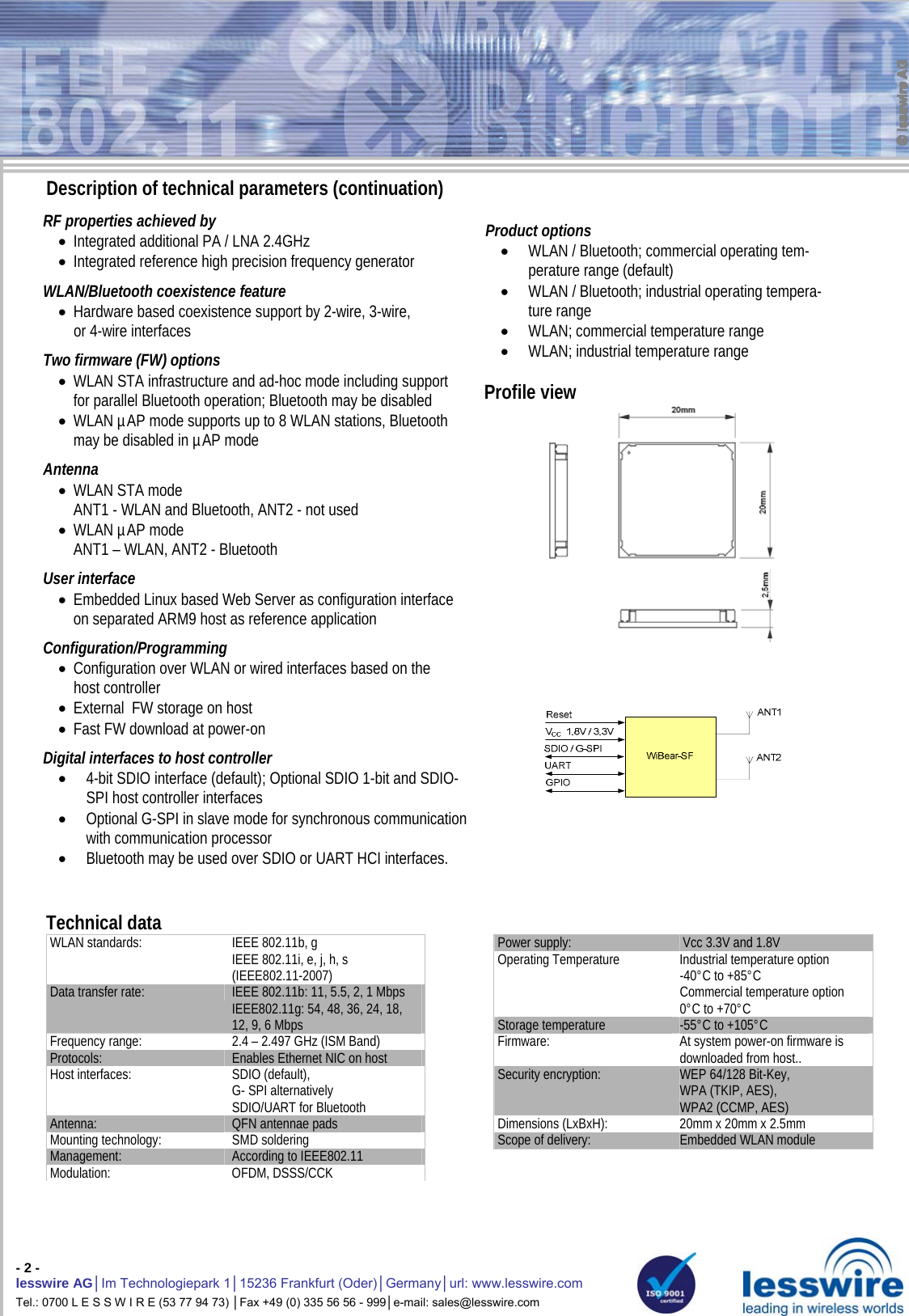
![- 3 - lesswire AG│Im Technologiepark 1│15236 Frankfurt (Oder)│Germany│url: www.lesswire.com Tel.: 0700 L E S S W I R E (53 77 94 73) │Fax +49 (0) 335 56 56 - 999│e-mail: sales@lesswire.com 45 PIN QFN Host Interface Power Supply PIN Signal Description 12, 13, 26 GND Ground 9 3V3 Module power supply +3.3V 10 VIO Module I/O supply (3.3V or 1.8V) 11 1V8 Module power supply +1.8V SDIO- / G-SPI Interface PIN Signal Description 1 SD_D2 / SPI_SINTn 1 SDIO 4-bit mode: Data line Bit 2 2 SD_D3 / SPI_CLK_REQ 1 SDIO 4-bit mode: Data line Bit 3 3 SD_CMD / SPI_SDI 1 SDIO 4-bit mode: Command/Response 4 SD_CLK / SPI_CLK 1 SDIO 4-bit mode: Clock 5 SD_D0 / SPI_SCSn 1 SDIO 4-bit mode: Data line Bit 0 6 SD_D1 / SPI_SDO 1 SDIO 4-bit mode: Data line Bit 1 LED PIN Signal Description 23 GPIO[17]/BT_LED LED function set by firmware 28 GPIO[1]/WLAN_LED LED function set by firmware Control PIN Signal Description 8 PDn Power Down 7 RESETn Module reset 14 SLEEP_CLK 2 Input for external sleep clock Bluetooth UART (max. up to 4Mbps) PIN Signal Description 15 GPIO[2]/UART_RTS UART RTS Output 16 GPIO[6]/UART_SOUT UART SOUT Output 17 GPIO[7]/UART_SINT UART SINT Input 19720 21 2215 16 17 1814 23 24 25 2689101112131234563332313029282739383736353445 44 43 42 41 401,60,61,272,543,815,086,357,62201,534,567,5 Mechanical drawing: Footprint on mother board 18 GPIO[8]/UART_CTS UART CTS Input General purpose IO Audio Interface Unit / Inter IC Sound PIN Signal Description PIN Signal Description 19 GPIO[3] 3 General purpose IO 31 GPIO[11]/BT_PCM_DIN PCM Data Input signal 20 GPIO[4] General purpose IO 32 GPIO[12]/BT_PCM_DOUT PCM Data Output signal 21 GPIO[5] 3 General purpose IO 33 GPIO[13]/BT_PCM_CLK PCM Clock Signal, output if master 22 GPIO[16] General purpose IO 34 GPIO[14]/BT_PCM_SYNC PCM Sync Pulse signal 27 GPIO[0] General purpose IO 35 GPIO[15]/BT_PCM_MCLK PCM Clock signal (optional for some Codecs) 29 GPIO[9] General purpose IO 30 GPIO[10] General purpose IO Antennae PIN Signal Description Bluetooth Coexistence 40 GND Antenna ground PIN Signal Description 41 ANT2 (BT only) Bluetooth antenna in µAP working mode 37 BT_PRIORITY Bluetooth priority 42 GND Antenna ground 38 BT_STATE Bluetooth state 43 GND Antenna ground 36 BT_FREQ Bluetooth frequency 44 ANT1 (WLAN / WLAN+BT) WLAN/Bluetooth antenna in station mode 39 WL_ACTIVE Bluetooth WLAN active 45 GND Antenna ground Notes: 1 Signal description provided for SDIO 4-bit / G-SPI mode. SDIO-SPI and SDIO -1bit mode are also supported. 2 External sleep clock for WLAN can be generated by internal clock source or may be provided by an external clock source. For Bluetooth operation in power save mode an external sleep clock is required (without power save an external clock for Bluetooth is not necessary). For Bluetooth Power Save mode external sleep clock 32.000 or 32.768 kHz frequency with tolerance ±50ppm is needed (ordinary watch fork quartz crystal conform to ±50ppm requirements at room temperature only, please check temperature characteristics before use). For WLAN external sleep clock any clock source with tolerance ±5000ppm can be used (Note that in this case internal sleep clock with the similar tolerance can be used as well). 3 Can be used as UART_DSR Input (GPIO[3]), UART_DTR Output (GPIO[5]) and as Bluetooth Wake-Up signals. Part number: AN00973535](https://usermanual.wiki/u-blox/WIBEAR-SF-UAP.AN00K73535-UserMan/User-Guide-1381783-Page-3.png)