u blox WIBEAR-SF-UAP The Lesswire industrial universal 802.11b/g WLAN + Bluetooth 2.1 module is targeted for integration into different products of OEM partners enabling them to communicate over WLAN and Bluetooth connection. User Manual WiBear SF engl v0 52
u-blox AG The Lesswire industrial universal 802.11b/g WLAN + Bluetooth 2.1 module is targeted for integration into different products of OEM partners enabling them to communicate over WLAN and Bluetooth connection. WiBear SF engl v0 52
u blox >
Contents
- 1. AN00K73535 UserMan
- 2. AN00K73535 InstGuide
- 3. 15_WIBEAR-SF_UAP UserMan
AN00K73535 UserMan
- 1 -
lesswire AG│Im Technologiepark 1│15236 Frankfurt (Oder)│Germany│url: www.lesswire.com
Tel.: 0700 L E S S W I R E (53 77 94 73) │Fax +49 (0) 335 56 56 - 999│e-mail: sales@lesswire.com
April 2010
Preliminary! Subject to technical modifications!
Universal embedded WLAN solution for OEM customers
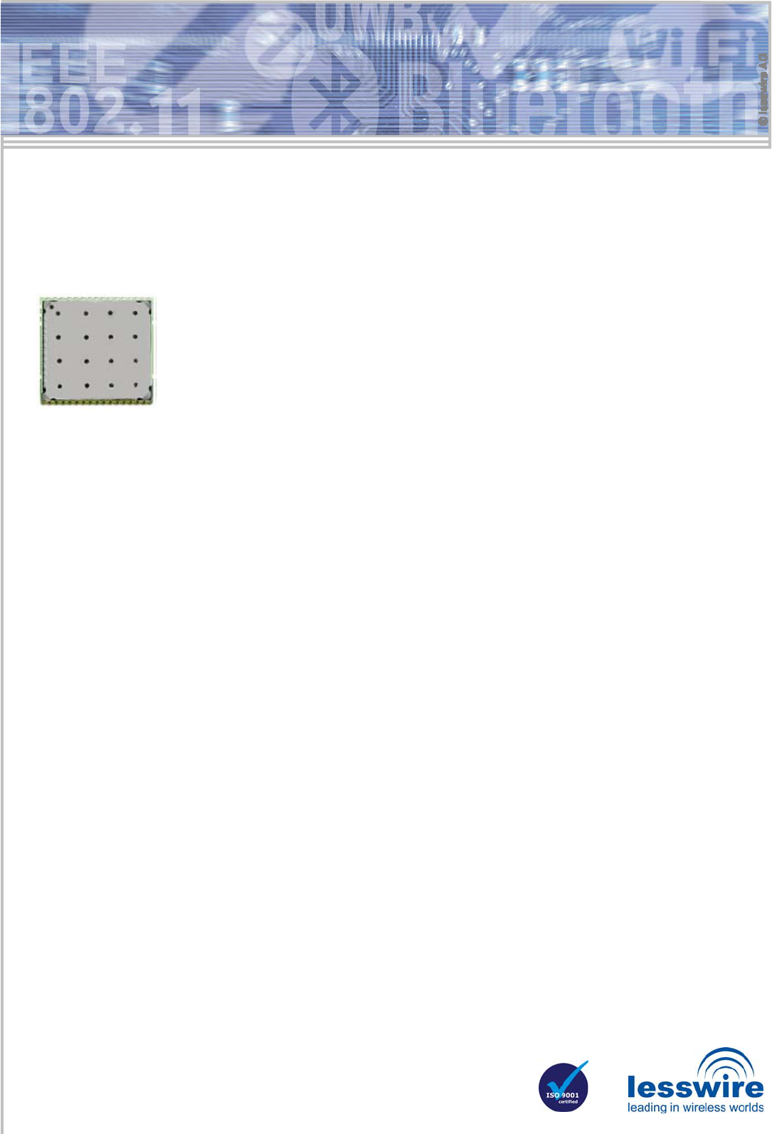
WiBear-SF - Industrial universal WLAN front end module (IEEE 802.11b/g)
The lesswire industrial universal WiBear-SF- WLAN module is a reliable, automotive grade WLAN front
end module. The module is developed for use in industrial temperature range from -40°C to +85°C.
The WiBear-SF WLAN module features the following key benefits:
• Extremely small and efficient footprint which covers 20 x 20 mm of size
• Simultaneous use of two different leading wireless standards, the IEEE 802.11b,g WLAN and a full
featured Bluetooth IEEE802.15.1 class 2 transceiver.
• Micro Access Point feature for building WLAN networks with the maximum number of 8 clients
The WiBear-SF WLAN module may be integrated in two ways into customer solutions:
• Deploy the processor of the existing design as host controller: The WLAN-SF module is connected to the customer processor
by SDIO or G-SPI interfaces. The WLAN stack will run on processor of the existing design.
• Add the WiBear-SF WLAN module together with a host controller to an existing design. As an example, the host controller may
be a based on ARM9 core. A corresponding reference design is available on request.
The host controller selection can consider additional needed interfaces like Ethernet, USB, CAN, or UART. The WiBear-SF
WLAN module is designed for industrial solutions in order to connect with already existing WLAN networks on shop floor.
Furthermore, an embedded Linux-based Web Server reference application is available to easily implement user-interfaces for
WLAN module configuration. The Bluetooth interface supports Bluetooth 2.1 and Enhanced Data Rate (EDR) operation. The
WiBear-SF complies with Bluetooth stacks that support SDIO or UART HCI protocol.
The WiBear-SF module is a compact one-side assembled design and can be soldered (SMD) onto a customer boards. The
availability of the module is guaranteed for minimum of 6 years
The universal WLAN module saves time and reduces costs. OEM customers can concentrate on their core competence while
adopting this easy to use WLAN module that can enable many wireless applications. For larger quantity orders lesswire can also
provide module design-ins. Driver porting to other operating systems can be offered by lesswire.
Description of technical parameters
-
WLAN
• IEEE802.11b Output power: typ. +18 dBm
Sensitivity: @ 1Mbps typ. -96 dBm
Sensitivity: @11Mbps typ. -89dBm
• IEEE802.11g Output power: typ. +15 dBm
Sensitivity: @ 6Mbps typ. -90dBm
Sensitivity: @12Mbps typ. -88dBm
Sensitivity: @54Mbps typ. -73dBm
-
Bluetooth
• IEEE802.15.1 Output power: typ. +8dBm
Sensitivity EDR typ. -75dBm
Sensitivity BDR typ. -86dBm
Bluetooth device class 2: typ. range ~10-20 m
Frequency range 2402MHz to 2480MHz
Number of channels 79
Modulation FHSS
-
Reference Designs
• SDIO / G-SPI Evaluation Board
• Reference design ARM9, 10 Mbps Ethernet, CAN,
USB, and Linux 2.6.28 including Linux BSP, drivers
Interfaces
• SDIO
• G-SPI
• Bluetooth coexistence
• UART
Driver Support
• Linux 2.6.x
• Windows CE, Windows XP/Vista
Bluetooth stack support
• Bluetooth 2.1 Basic Data Rate (BDR) and Enhanced
Data Rate (EDR) operation
• Bluetooth stacks that support UART HCI protocol
- 2 -
lesswire AG│Im Technologiepark 1│15236 Frankfurt (Oder)│Germany│url: www.lesswire.com
Tel.: 0700 L E S S W I R E (53 77 94 73) │Fax +49 (0) 335 56 56 - 999│e-mail: sales@lesswire.com
Description of technical parameters (continuation)
Technical data
WLAN standards: IEEE 802.11b, g
IEEE 802.11i, e, j, h, s
(IEEE802.11-2007)
Data transfer rate: IEEE 802.11b: 11, 5.5, 2, 1 Mbps
IEEE802.11g: 54, 48, 36, 24, 18,
12, 9, 6 Mbps
Frequency range: 2.4 – 2.497 GHz (ISM Band)
Protocols: Enables Ethernet NIC on host
Host interfaces: SDIO (default),
G- SPI alternatively
SDIO/UART for Bluetooth
Antenna: QFN antennae pads
Mounting technology: SMD soldering
Management: According to IEEE802.11
Modulation: OFDM, DSSS/CCK
Power supply: Vcc 3.3V and 1.8V
Operating Temperature Industrial temperature option
-40°C to +85°C
Commercial temperature option
0°C to +70°C
Storage temperature -55°C to +105°C
Firmware: At system power-on firmware is
downloaded from host..
Security encryption: WEP 64/128 Bit-Key,
WPA (TKIP, AES),
WPA2 (CCMP, AES)
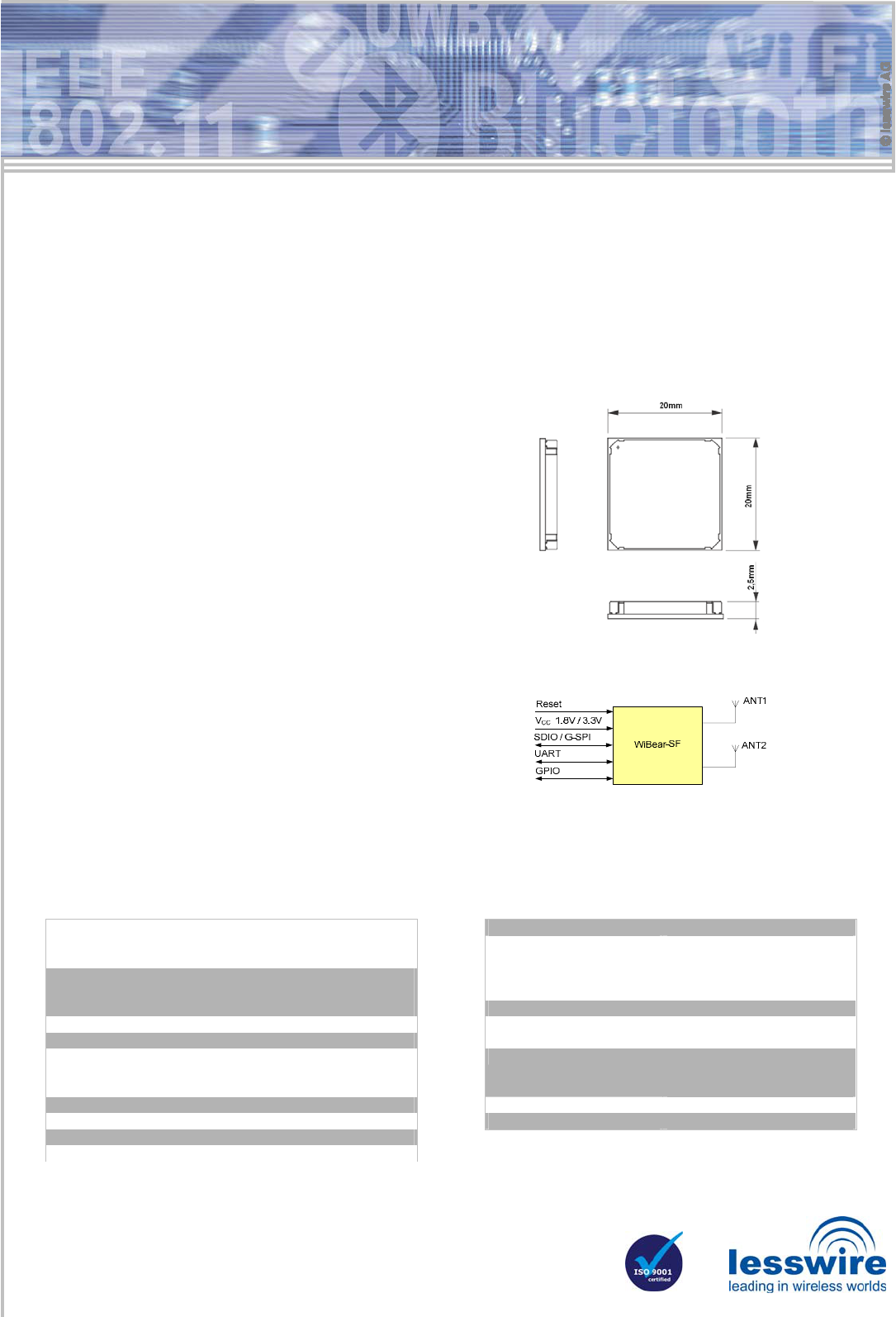
Dimensions (LxBxH): 20mm x 20mm x 2.5mm
Scope of delivery: Embedded WLAN module
Product options
• WLAN / Bluetooth; commercial operating tem-
perature range (default)
• WLAN / Bluetooth; industrial operating tempera-
ture range
• WLAN; commercial temperature range
• WLAN; industrial temperature range
Profile view
RF properties achieved by
• Integrated additional PA / LNA 2.4GHz
• Integrated reference high precision frequency generator
WLAN/Bluetooth coexistence feature
• Hardware based coexistence support by 2-wire, 3-wire,
or 4-wire interfaces
Two firmware (FW) options
• WLAN STA infrastructure and ad-hoc mode including support
for parallel Bluetooth operation; Bluetooth may be disabled
• WLAN µAP mode supports up to 8 WLAN stations, Bluetooth
may be disabled in µAP mode
Antenna
• WLAN STA mode
ANT1 - WLAN and Bluetooth, ANT2 - not used
• WLAN µAP mode
ANT1 – WLAN, ANT2 - Bluetooth
User interface
• Embedded Linux based Web Server as configuration interface
on separated ARM9 host as reference application
Configuration/Programming
• Configuration over WLAN or wired interfaces based on the
host controller
• External FW storage on host
• Fast FW download at power-on
Digital interfaces to host controller
• 4-bit SDIO interface (default); Optional SDIO 1-bit and SDIO-
SPI host controller interfaces
• Optional G-SPI in slave mode for synchronous communication
with communication processor
• Bluetooth may be used over SDIO or UART HCI interfaces.
- 3 -
lesswire AG│Im Technologiepark 1│15236 Frankfurt (Oder)│Germany│url: www.lesswire.com
Tel.: 0700 L E S S W I R E (53 77 94 73) │Fax +49 (0) 335 56 56 - 999│e-mail: sales@lesswire.com
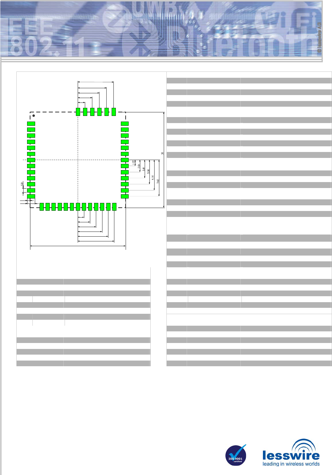
45 PIN QFN Host Interface Power Supply
PIN Signal Description
12, 13, 26 GND Ground
9 3V3 Module power supply +3.3V
10 VIO Module I/O supply (3.3V or 1.8V)
11 1V8 Module power supply +1.8V
SDIO- / G-SPI Interface
PIN Signal Description
1 SD_D2 / SPI_SINTn 1 SDIO 4-bit mode: Data line Bit 2
2 SD_D3 / SPI_CLK_REQ 1 SDIO 4-bit mode: Data line Bit 3
3 SD_CMD / SPI_SDI 1 SDIO 4-bit mode: Command/Response
4 SD_CLK / SPI_CLK 1 SDIO 4-bit mode: Clock
5 SD_D0 / SPI_SCSn 1 SDIO 4-bit mode: Data line Bit 0
6 SD_D1 / SPI_SDO 1 SDIO 4-bit mode: Data line Bit 1
LED
PIN Signal Description
23 GPIO[17]/BT_LED LED function set by firmware
28 GPIO[1]/WLAN_LED LED function set by firmware
Control
PIN Signal Description
8 PDn Power Down
7 RESETn Module reset
14 SLEEP_CLK
2 Input for external sleep clock
Bluetooth UART (max. up to 4Mbps)
PIN Signal Description
15 GPIO[2]/UART_RTS UART RTS Output
16 GPIO[6]/UART_SOUT UART SOUT Output
17 GPIO[7]/UART_SINT UART SINT Input
19
7
20 21 2215 16 17 1814 23 24 25 26
8
9
10
11
12
13
1
2
3
4
5
6
33
32
31
30
29
28
27
39
38
37
36
35
34
45 44 43 42 41 40
1,6
0,6
1,27
2,54
3,81
5,08
6,35
7,62
20
1,5
3
4,5
6
7,5
Mechanical drawing: Footprint on mother board 18 GPIO[8]/UART_CTS UART CTS Input
General purpose IO
Audio Interface Unit / Inter IC Sound
PIN Signal Description PIN Signal Description
19 GPIO[3]
3 General purpose IO 31 GPIO[11]/BT_PCM_DIN PCM Data Input signal
20 GPIO[4] General purpose IO 32 GPIO[12]/BT_PCM_DOUT PCM Data Output signal
21 GPIO[5]
3 General purpose IO 33 GPIO[13]/BT_PCM_CLK PCM Clock Signal, output if master
22 GPIO[16] General purpose IO 34 GPIO[14]/BT_PCM_SYNC PCM Sync Pulse signal
27 GPIO[0] General purpose IO 35 GPIO[15]/BT_PCM_MCLK PCM Clock signal (optional for some Codecs)
29 GPIO[9] General purpose IO
30 GPIO[10] General purpose IO
Antennae
PIN Signal Description
Bluetooth Coexistence 40 GND Antenna ground
PIN Signal Description 41 ANT2 (BT only) Bluetooth antenna in µAP working mode
37 BT_PRIORITY Bluetooth priority 42 GND Antenna ground
38 BT_STATE Bluetooth state 43 GND Antenna ground
36 BT_FREQ Bluetooth frequency 44 ANT1 (WLAN / WLAN+BT) WLAN/Bluetooth antenna in station mode
39 WL_ACTIVE Bluetooth WLAN active 45 GND Antenna ground
Notes:
1 Signal description provided for SDIO 4-bit / G-SPI mode. SDIO-SPI and SDIO -1bit mode are also supported.
2 External sleep clock for WLAN can be generated by internal clock source or may be provided by an external clock source. For Bluetooth
operation in power save mode an external sleep clock is required (without power save an external clock for Bluetooth is not necessary).
For Bluetooth Power Save mode external sleep clock 32.000 or 32.768 kHz frequency with tolerance ±50ppm is needed (ordinary watch
fork quartz crystal conform to ±50ppm requirements at room temperature only, please check temperature characteristics before use). For
WLAN external sleep clock any clock source with tolerance ±5000ppm can be used (Note that in this case internal sleep clock with the
similar tolerance can be used as well).
3 Can be used as UART_DSR Input (GPIO[3]), UART_DTR Output (GPIO[5]) and as Bluetooth Wake-Up signals.
Part number: AN00973535