u blox WTB08 WAGO Bluetooth Terminal 750-644 User Manual 750 644
u-blox AG WAGO Bluetooth Terminal 750-644 750 644
UserManual.wiki
>
u blox
>
WTB08 User Manual
UserMan
Navigation menu
Upload a User Manual
Namespaces
Wiki Guide
HTML
PDF
Info
Views
User Manual
Discussion / Help
Navigation
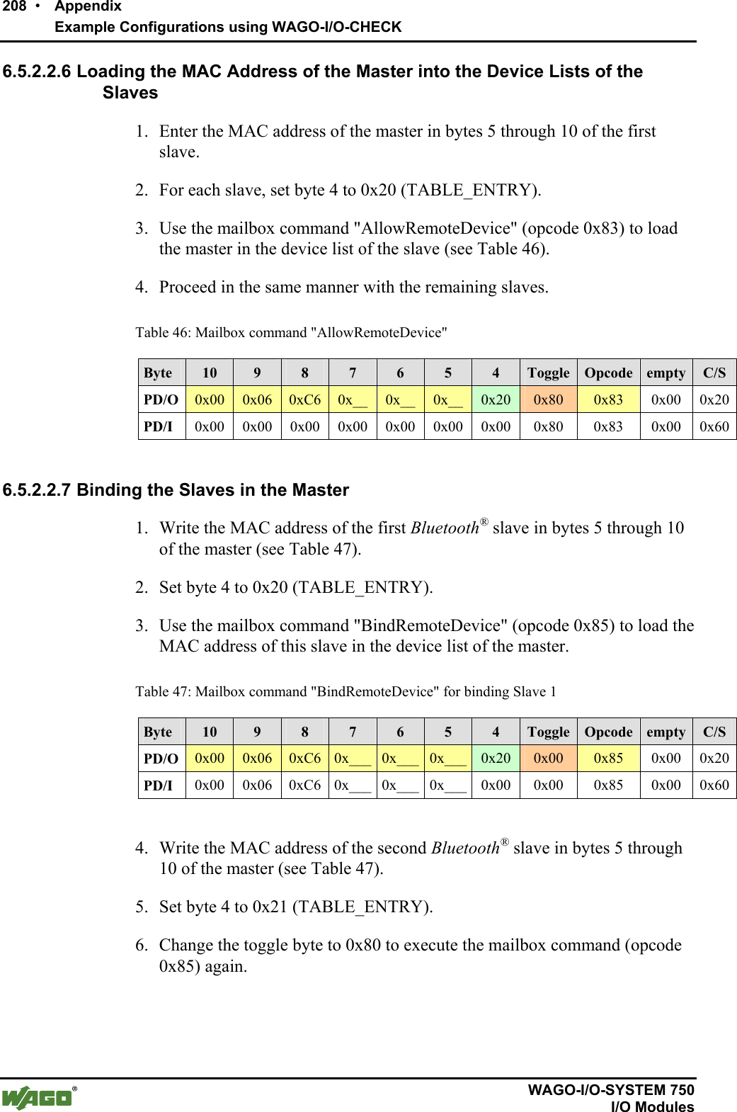
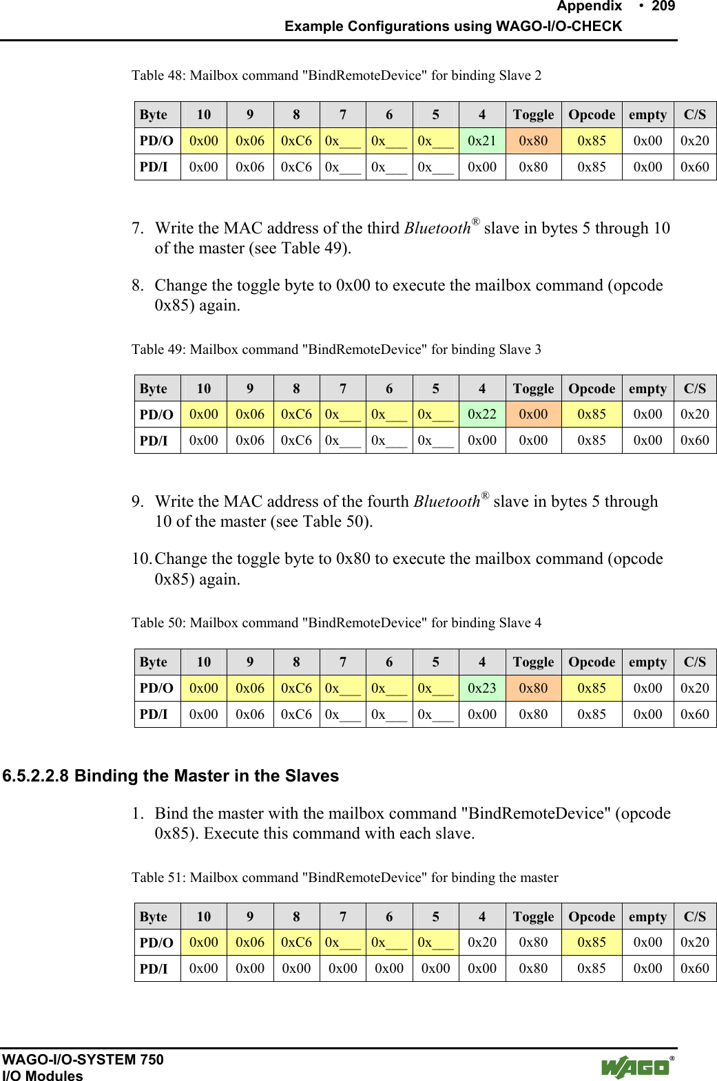
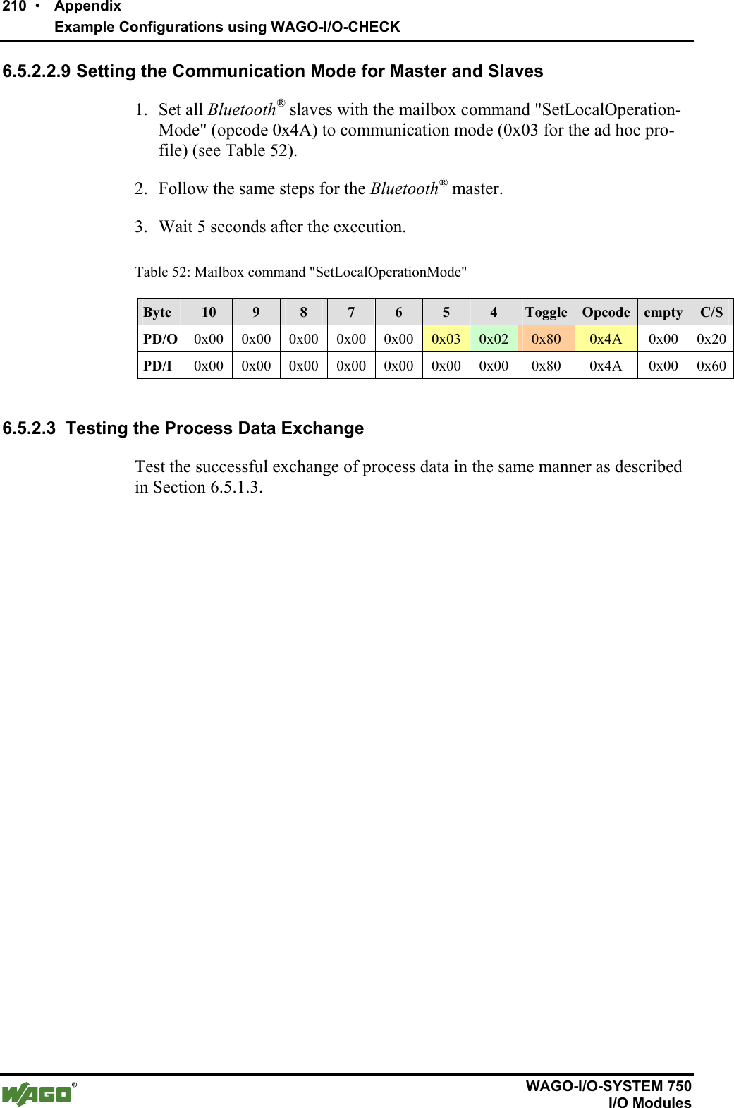
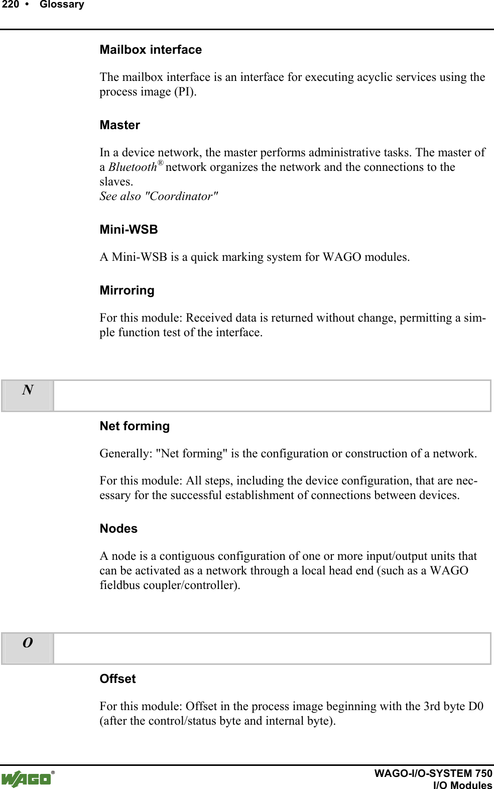
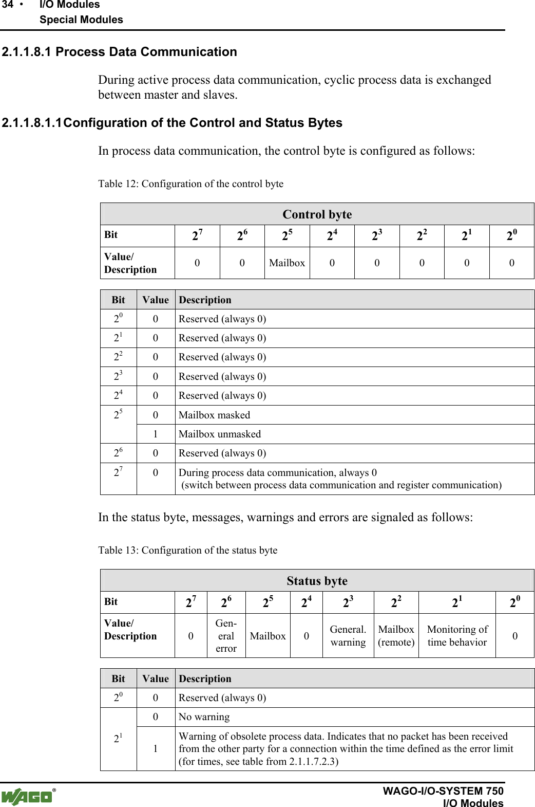
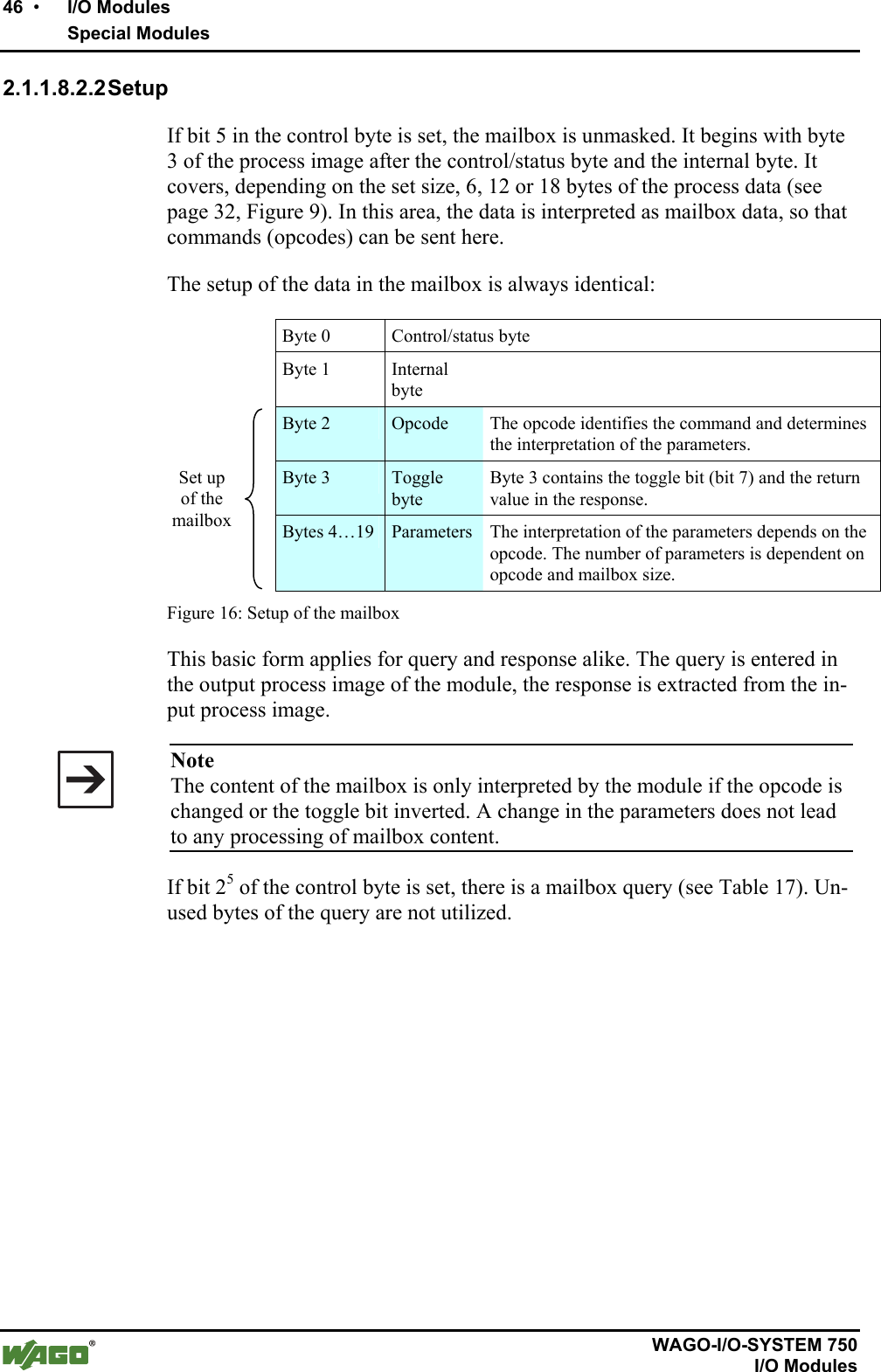
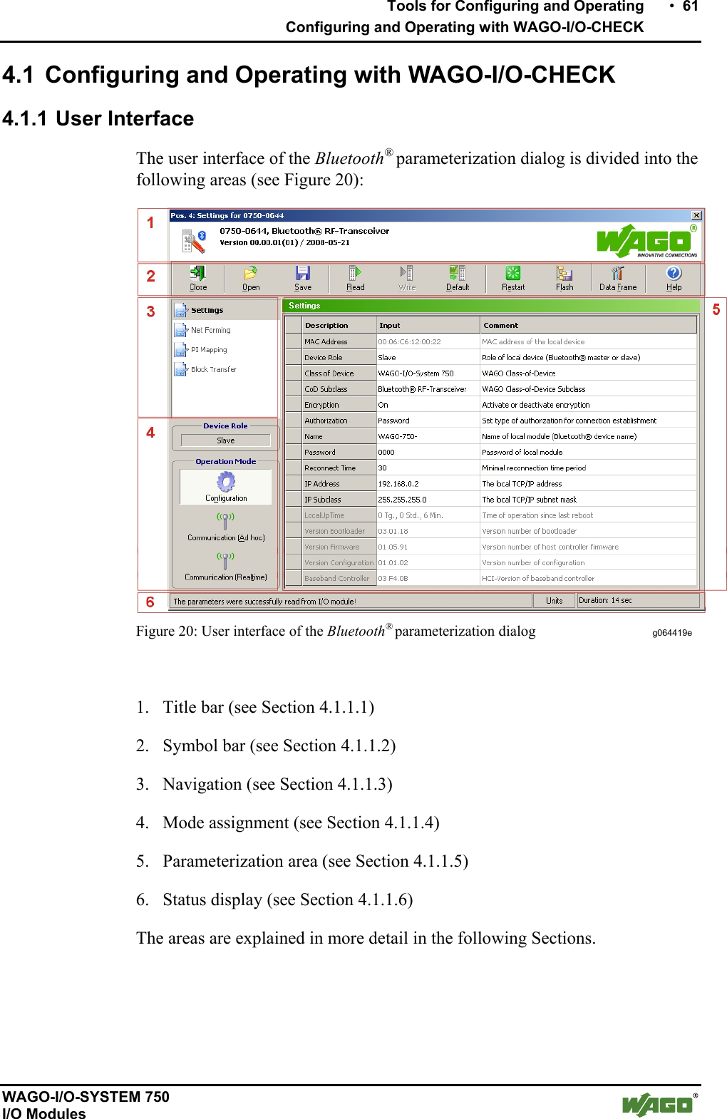
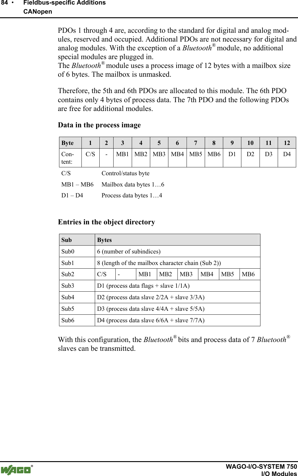
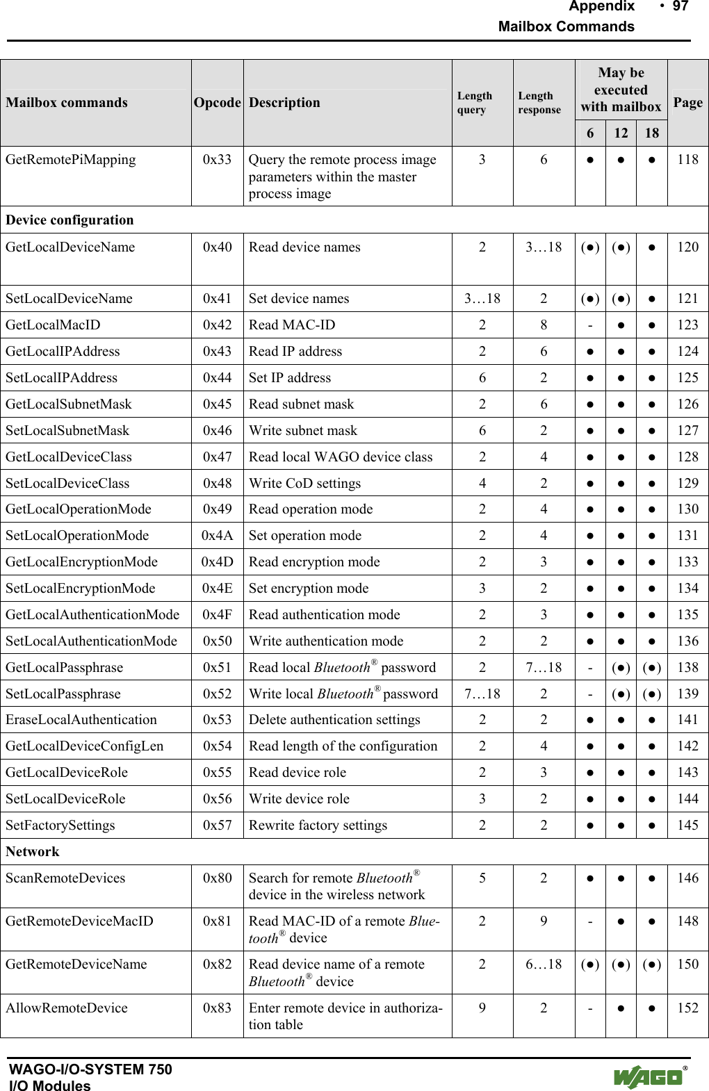
![Important Comments • 3 Legal Principles WAGO-I/O-SYSTEM 750 I/O Modules Content 1 Important Comments ................................................................................. 7 1.1 Legal Principles........................................................................................7 1.1.1 Copyright............................................................................................. 7 1.1.2 Personnel Qualification .......................................................................7 1.1.3 Intended Use........................................................................................ 7 1.2 Symbols....................................................................................................8 1.3 Number Notation......................................................................................8 1.4 Safety Notes .............................................................................................9 1.5 Scope ........................................................................................................7 2 I/O Modules ............................................................................................... 10 2.1 Special Modules .....................................................................................10 2.1.1 750-644 [Bluetooth® RF Transceiver]...............................................10 2.1.1.1 View..............................................................................................10 2.1.1.2 Description....................................................................................10 2.1.1.3 Indicators.......................................................................................13 2.1.1.4 Schematic Diagram.......................................................................15 2.1.1.5 Technical Data ..............................................................................15 2.1.1.6 Function Description.....................................................................17 2.1.1.7 Operating Modes...........................................................................21 2.1.1.8 Process Image ...............................................................................31 3 Configuration of a Bluetooth® Piconet .................................................... 58 4 Tools for Configuring and Operating ..................................................... 60 4.1 Configuring and Operating with WAGO-I/O-CHECK..........................61 4.1.1 User Interface ....................................................................................61 4.1.1.1 Title Bar ........................................................................................62 4.1.1.2 Symbol Bar ...................................................................................62 4.1.1.3 Navigation.....................................................................................63 4.1.1.4 Mode Assignment .........................................................................64 4.1.1.5 Parameterization Area...................................................................65 4.1.1.6 Status Display ...............................................................................77 4.2 Configuring the Bluetooth® Module 750-644 ........................................78 4.2.1 Setting the Bluetooth® Process Data and Mailbox Size.....................78 4.2.2 Setting the Mode................................................................................ 78 4.2.3 Role Assignment (Master/Slave).......................................................79 4.2.4 Search for and Display Devices within Range .................................. 79 4.2.5 Bind new Devices..............................................................................79 4.2.5.1 Entering Bluetooth® Devices manually ........................................79 4.2.5.2 Bind Bluetooth® Devices from Network Search...........................80 4.2.6 Assigning Slave Process Data to Slots in the Master ........................81 4.2.7 Diagnostics ........................................................................................81](https://usermanual.wiki/u-blox/WTB08/User-Guide-1066128-Page-3.png)
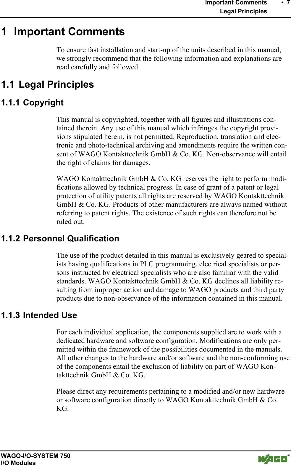
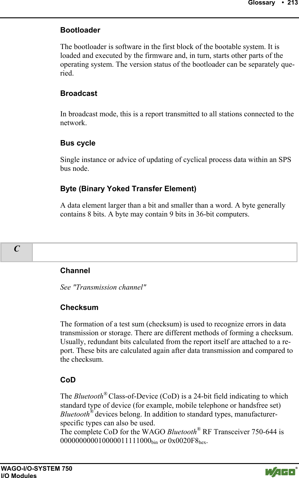
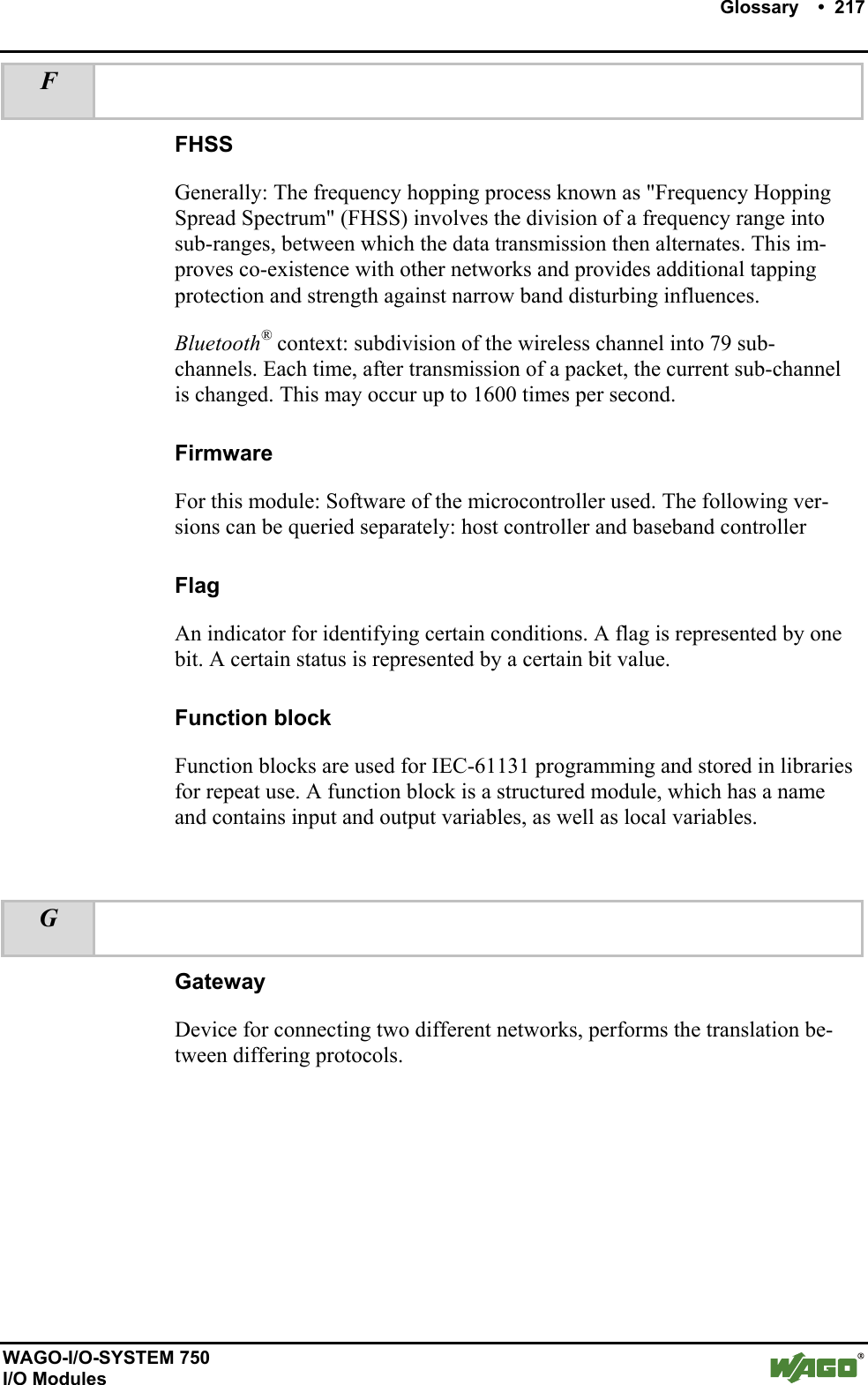
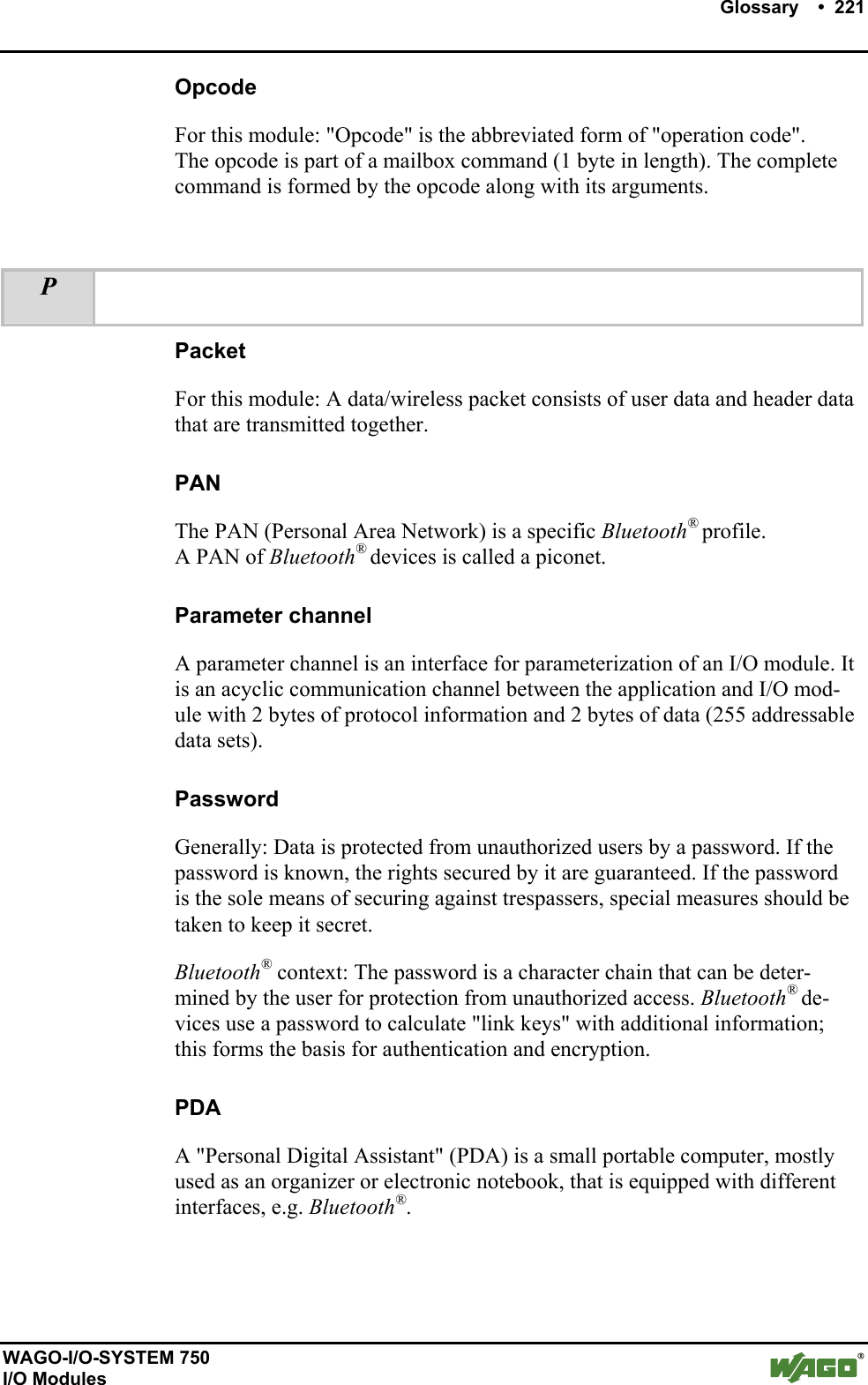
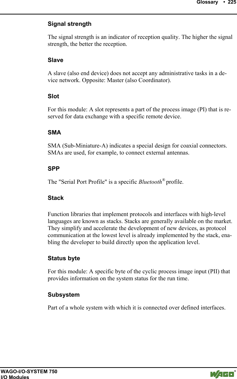
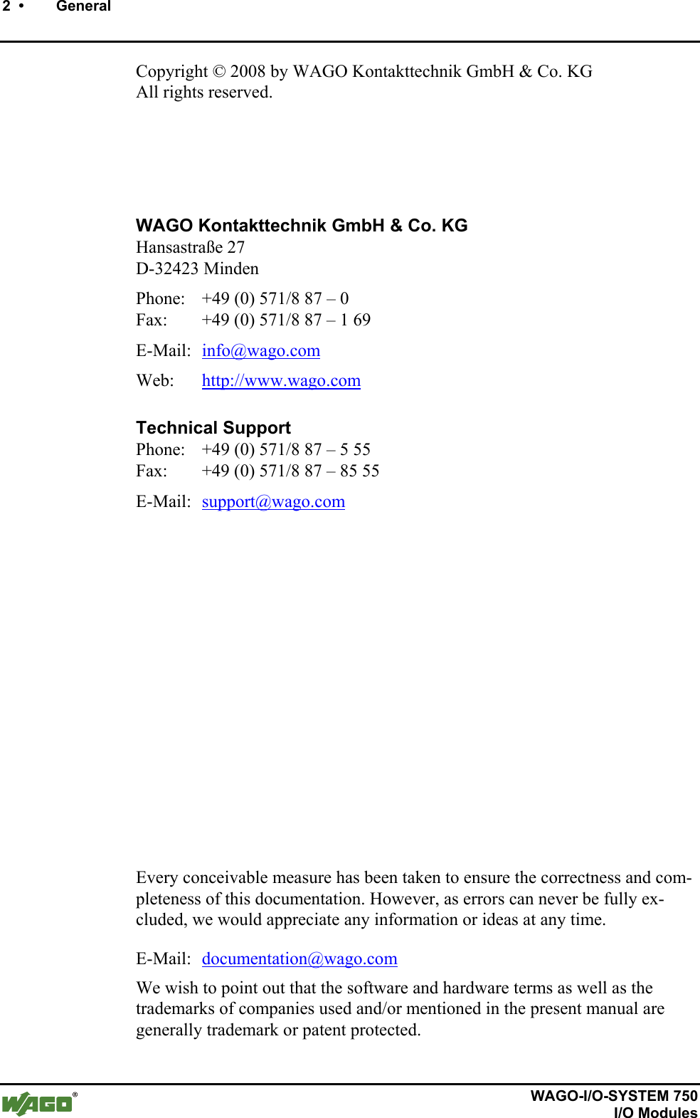
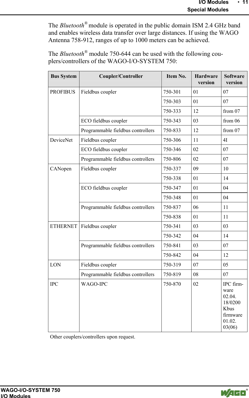
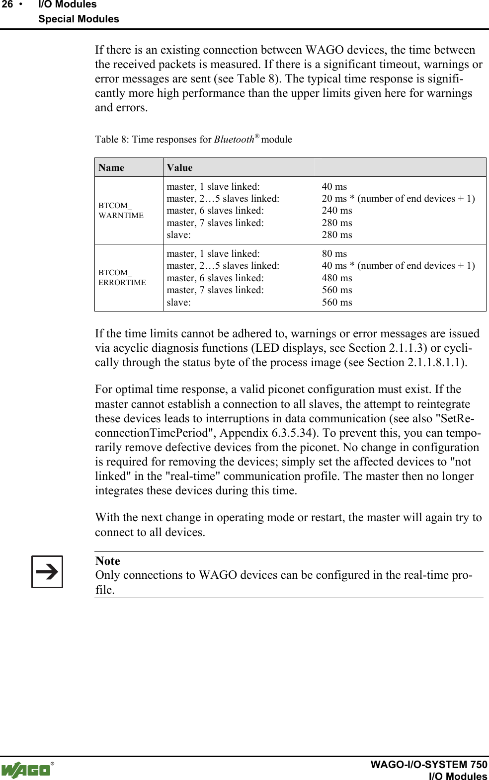
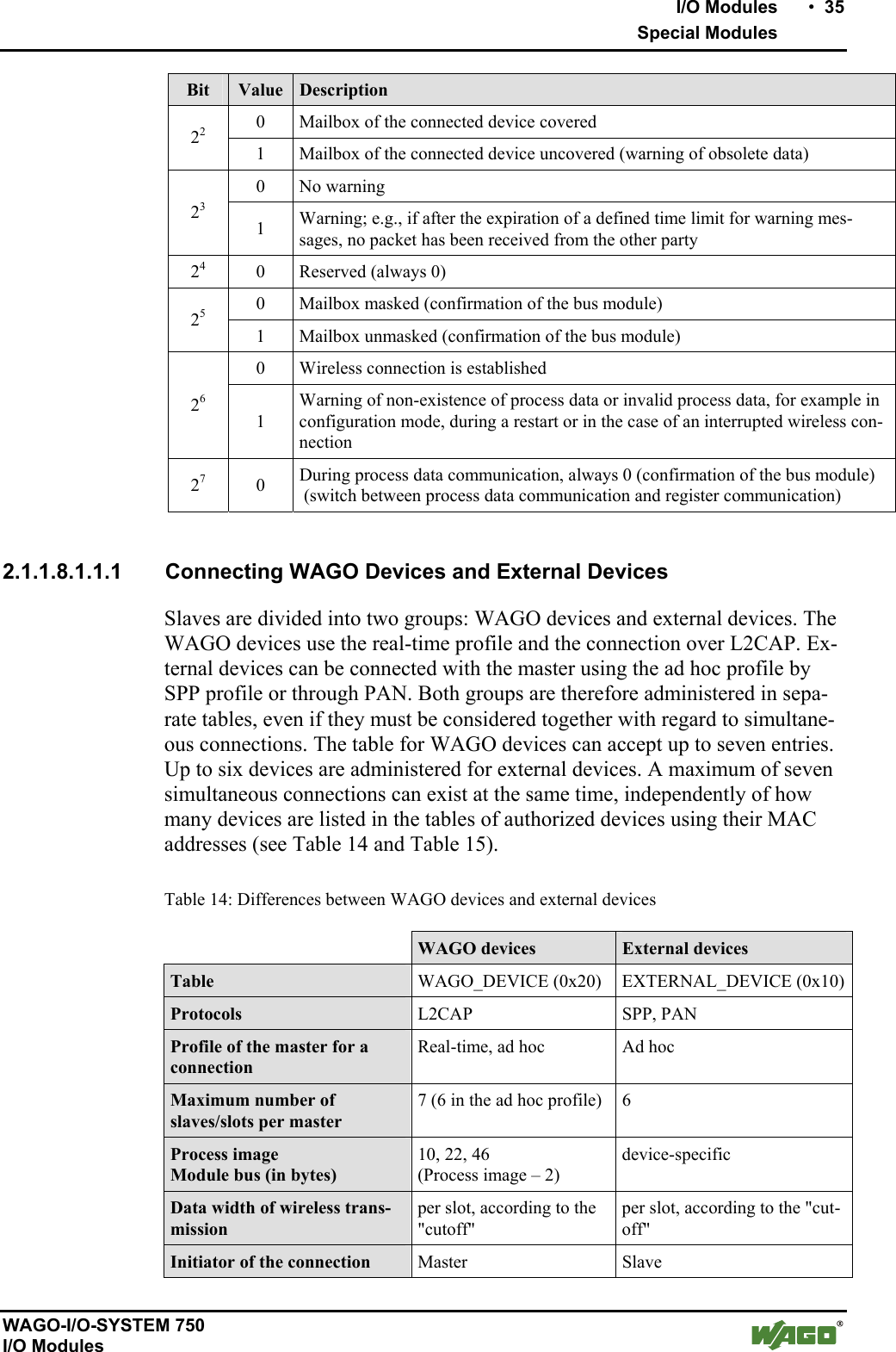
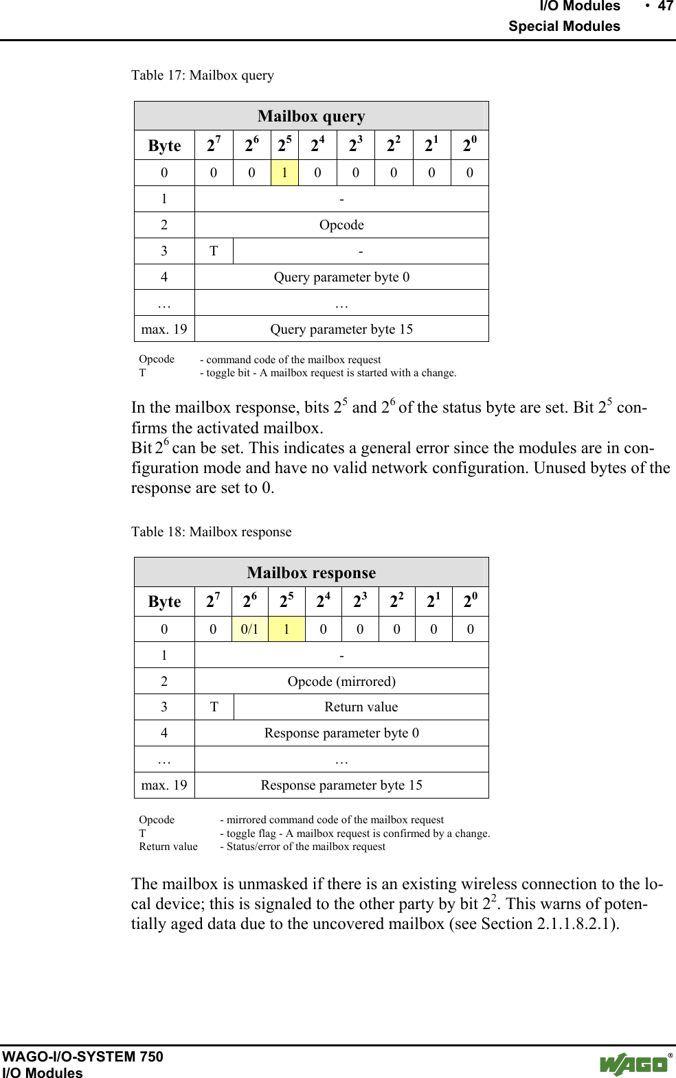
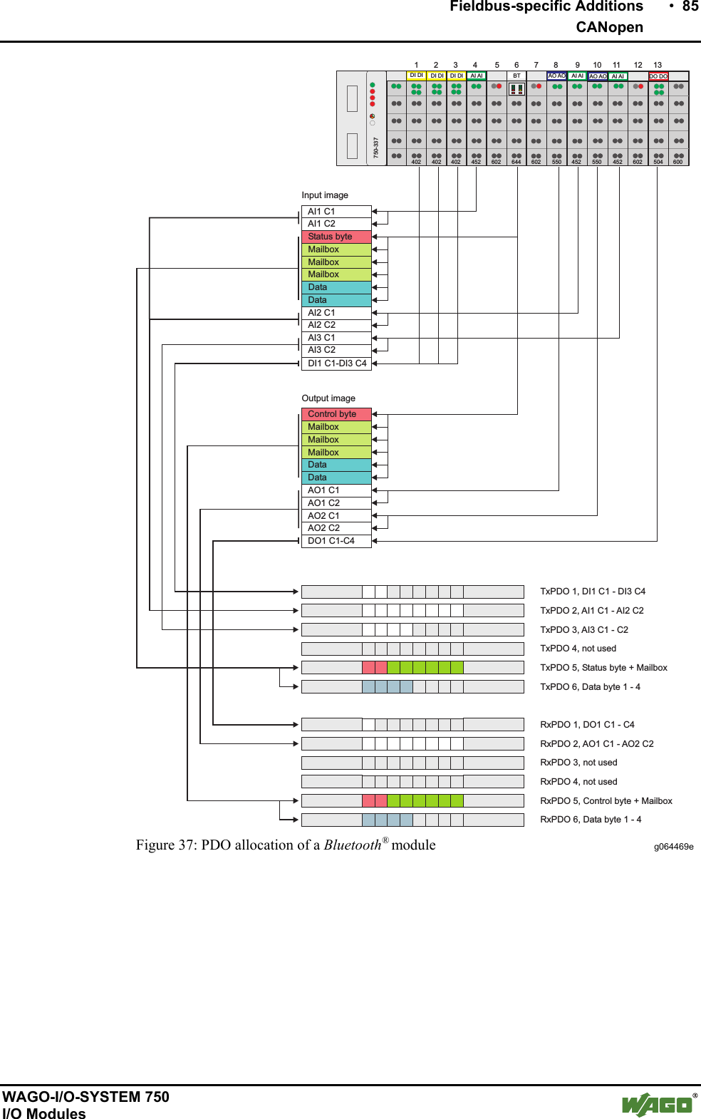
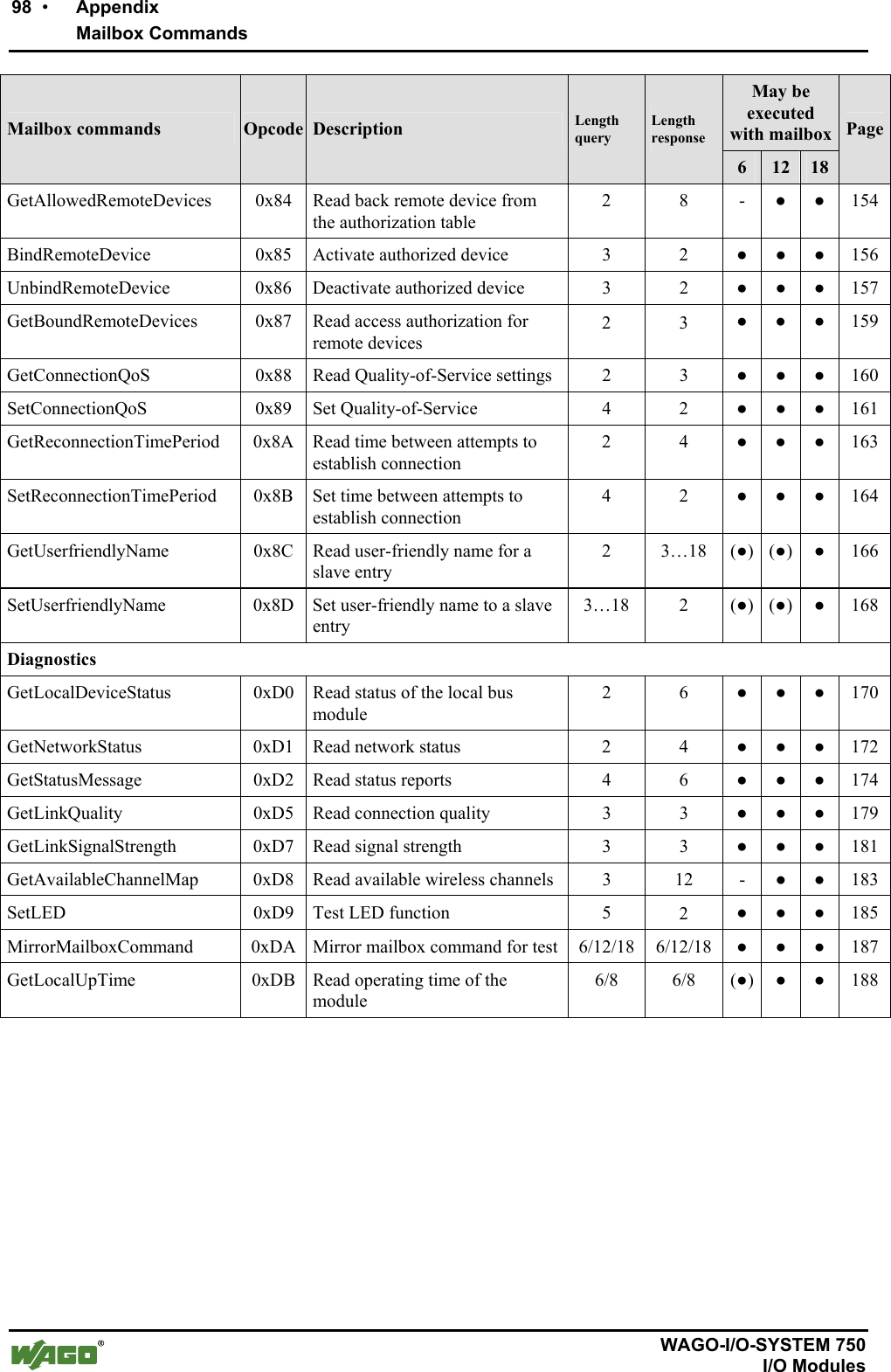
![10 • I/O Modules Special Modules WAGO-I/O-SYSTEM 750 I/O Modules 2 I/O Modules 2.1 Special Modules 2.1.1 750-644 [Bluetooth® RF Transceiver] 2.1.1.1 View 13 14750-644Antenna socketSMAData contactsPower jumpercontactsOperational andconnectionstatus Figure 1: View g064400e 2.1.1.2 Description The Bluetooth® RF Transceiver 750-644 (referred to in the following as "Blue-tooth® module") integrates a Bluetooth® network (piconet) into the WAGO-I/O-SYSTEM 750. This means that Bluetooth® modules will be installed and used jointly with the WAGO-I/O-SYSTEM 750 modules in different fieldbus systems. The Bluetooth® module facilitates wireless data exchange within the Bluetooth® piconet. It can function as the coordinator (referred to in the following as the "master") or as the terminal (referred to in the following as the "slave") depending on the configuration. A maximum of seven slaves may communicate with one master (see Figure 2). MasterSlave1Slave2Slave3Slave7Slave6Slave5Slave4 Figure 2: Piconet g064403x The module's configuration (network configuration/process image mapping) is determined locally via WAGO-I/O-CHECK software. The current status of the module is displayed by LEDs. While the LEDs asso-ciated with the function of "slave" signal the quality of the connection, the LEDs associated with the "master" function show the connection status to each individually connected slave.](https://usermanual.wiki/u-blox/WTB08/User-Guide-1066128-Page-10.png)
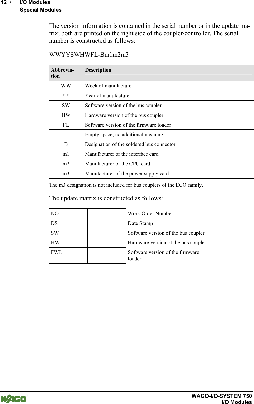
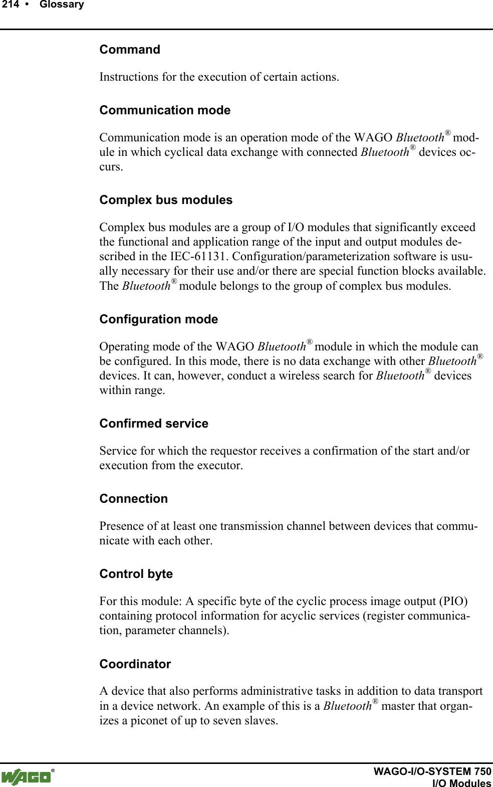
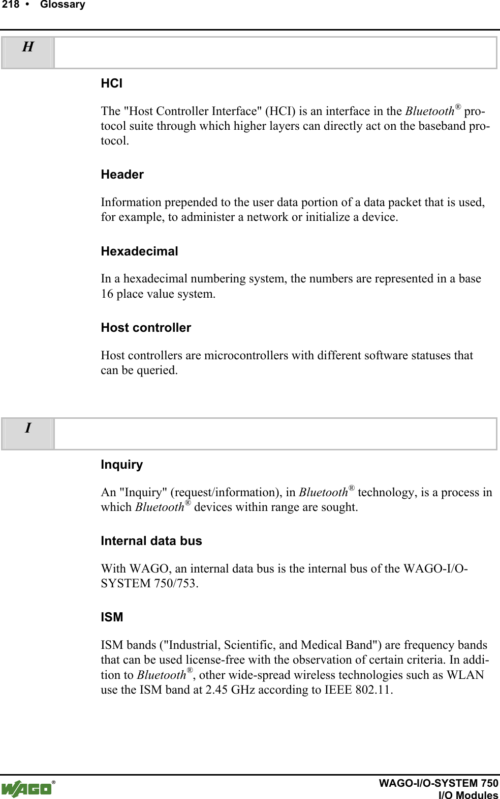
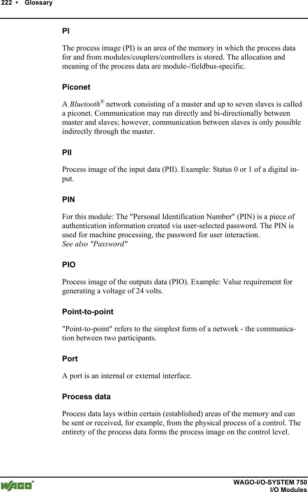
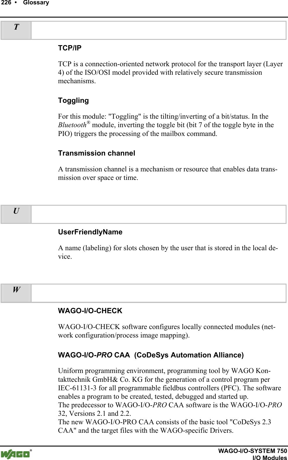
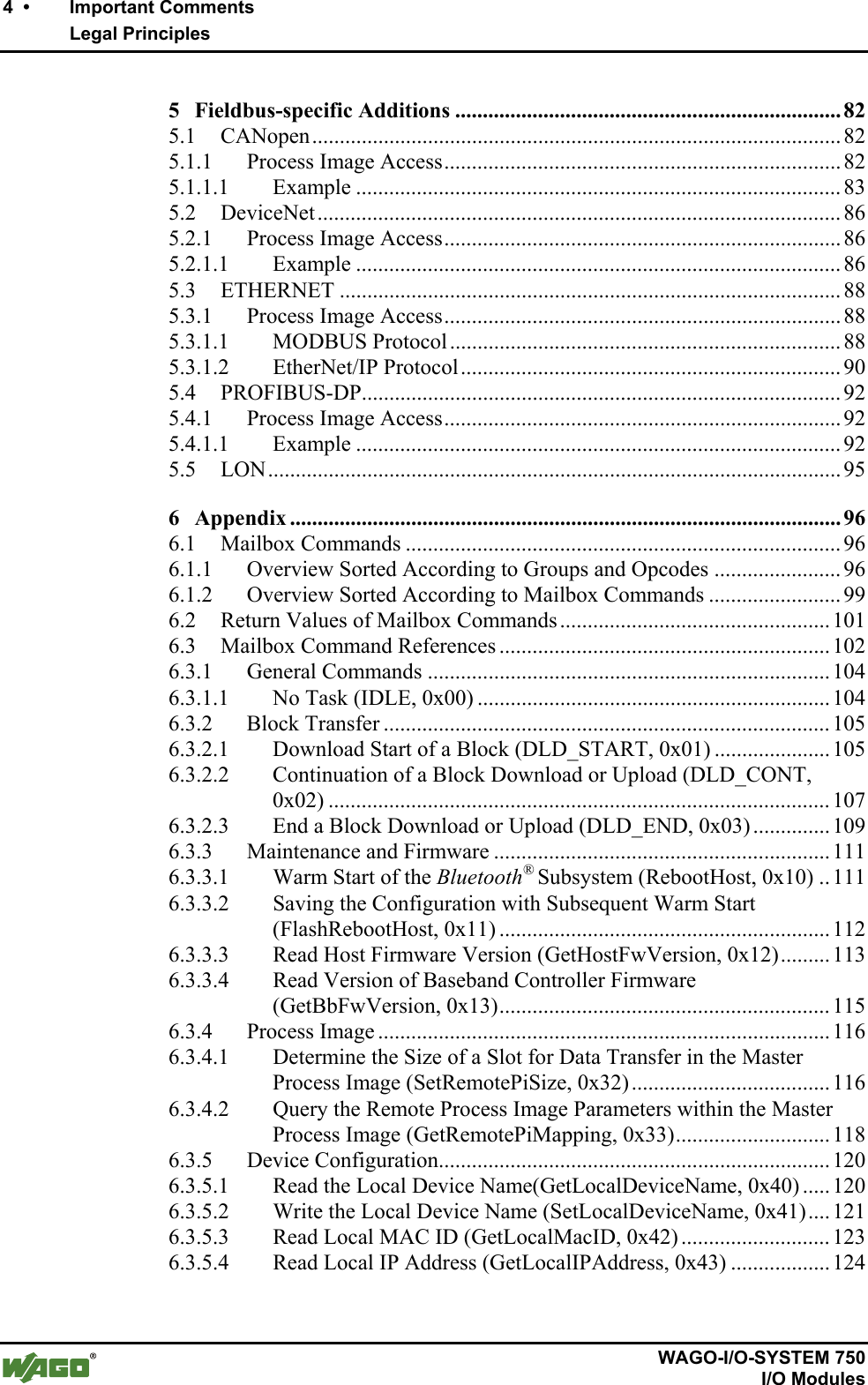
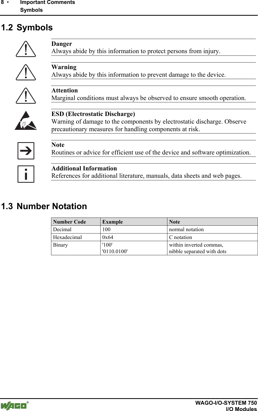
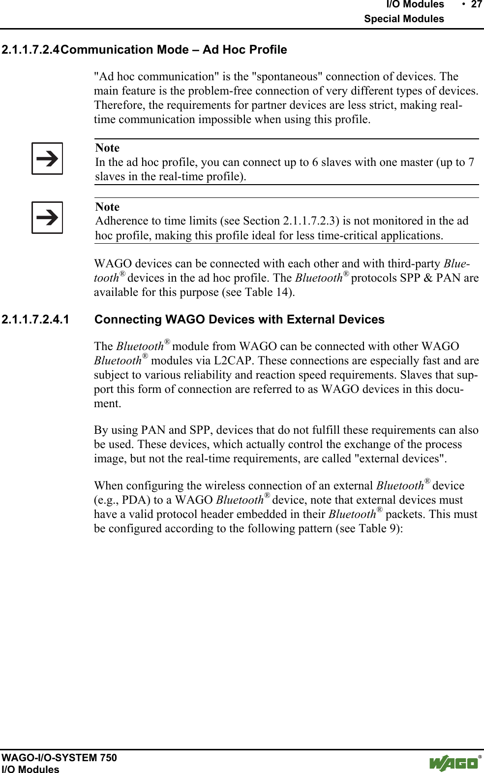
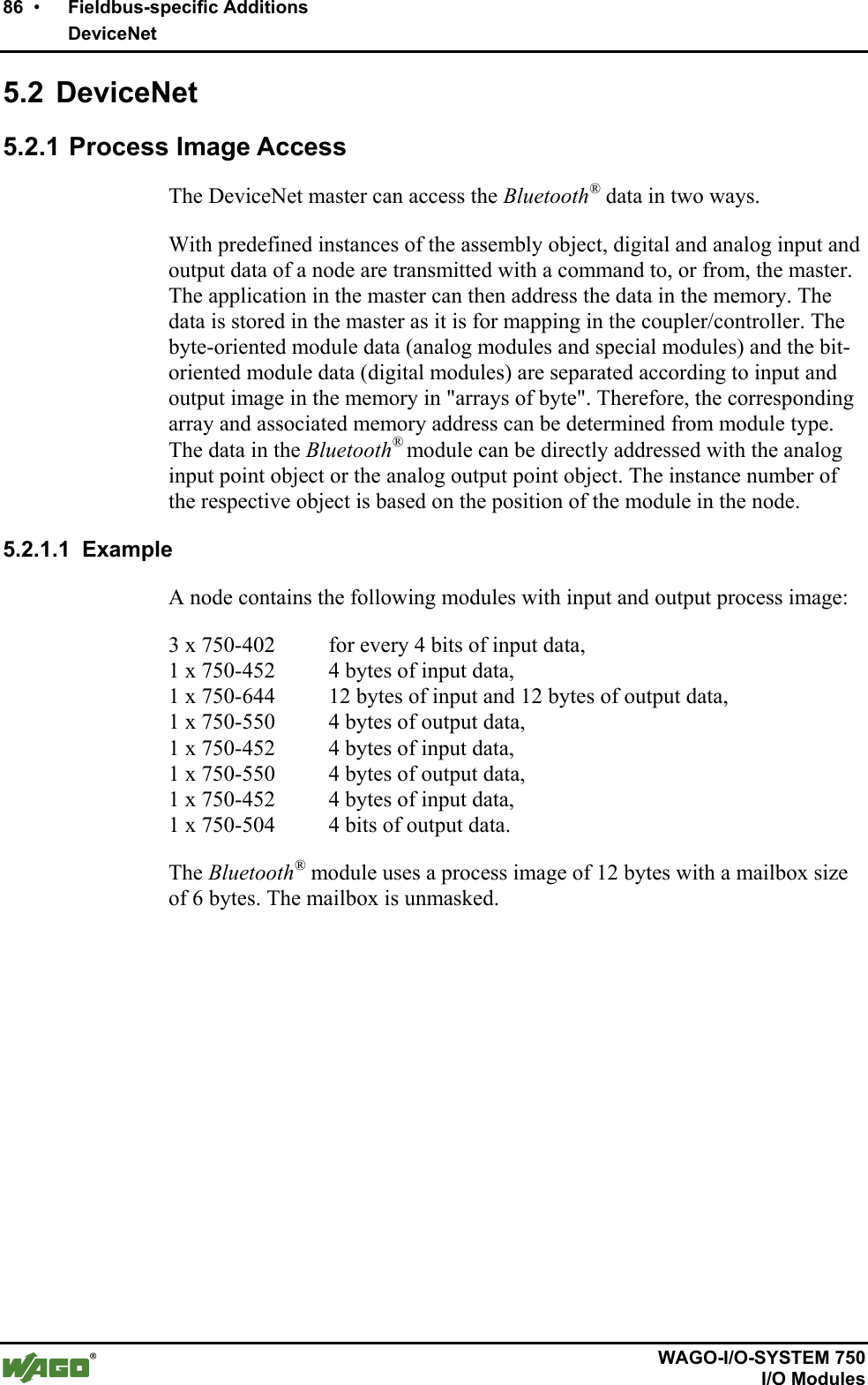
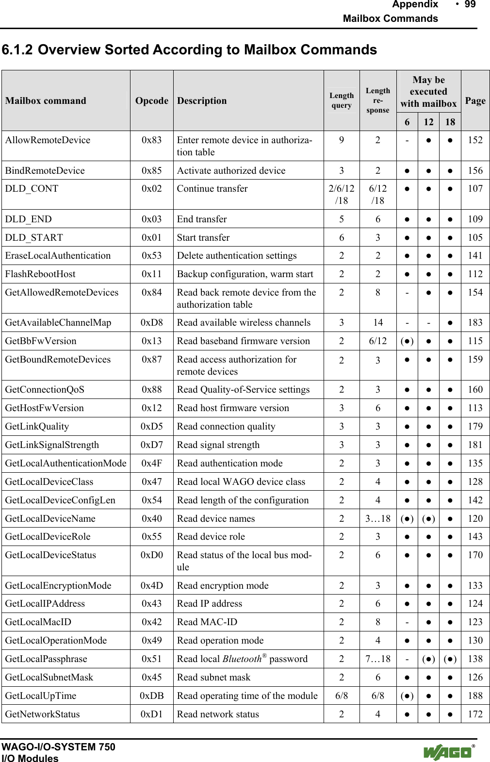
![16 • I/O Modules Special Modules WAGO-I/O-SYSTEM 750 I/O Modules Module-Specific Data Diagnosis (through optical display) Device status, connection status [1] Diagnosis (through process image) Device status, connection status [1], time monitoring Configuration WAGO-I/O-CHECK and WAGO-I/O-PRO CAA Dimensions (mm) W x H x L 24 x 64 [2] x 100 Weight approx. 85 g Accessories Miniature WSB Quick marking system External WAGO antenna, SMA, with magnet base (item no. 758-912) Standards and directives (see Section 2.2 in manual on coupler/controller) EMC CE Immunity to interference according to EN 61000-6-2 (2005), EN 61131-2 (2003) EMC CE Emission of interference according to EN 61000-6-3 (2007), EN 61131-2 (2003) Approvals (see Section 2.2 in manual on coupler/controller) CULUS (UL508) (patent pending) GL (Germanischer Lloyd) (patent pending) Conformity marking FCC approval [3] Bluetooth® approval [1] Quality of the radio link, signal strength, interference [2] plus approx. 6.5 mm excess length of the SMA socket [3] This device complies with Part 15 of the FCC Rules. Operation is subject to the following two condi-tions: (1) this device may not cause harmful interference, and (2) this device must accept any interfer-ence received, including interference that may cause undesired operation. Additional Information Please refer to the "Overview on WAGO-I/O-SYSTEM 750 approvals" docu-mentation for detailed information on approvals. You will find this on the CD ROM "AUTOMATION Tools and Docs" (item no. 0888-0412) or online at http://www.wago.com under documentation ! WAGO-I/O-SYSTEM 750 ! System Description](https://usermanual.wiki/u-blox/WTB08/User-Guide-1066128-Page-16.png)
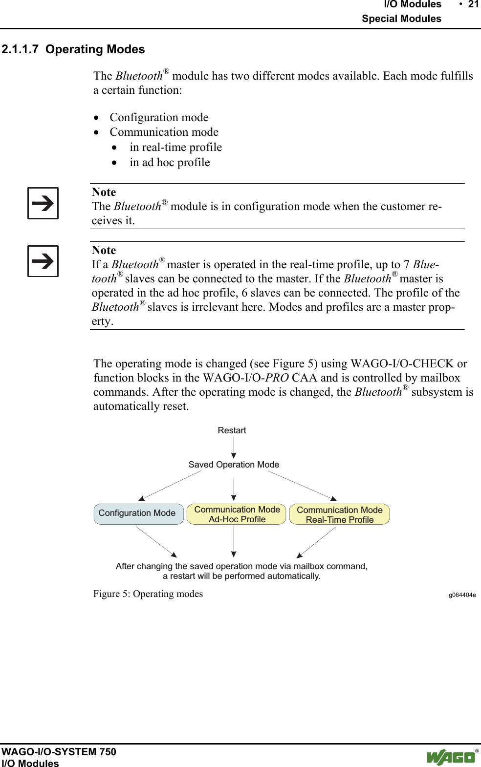
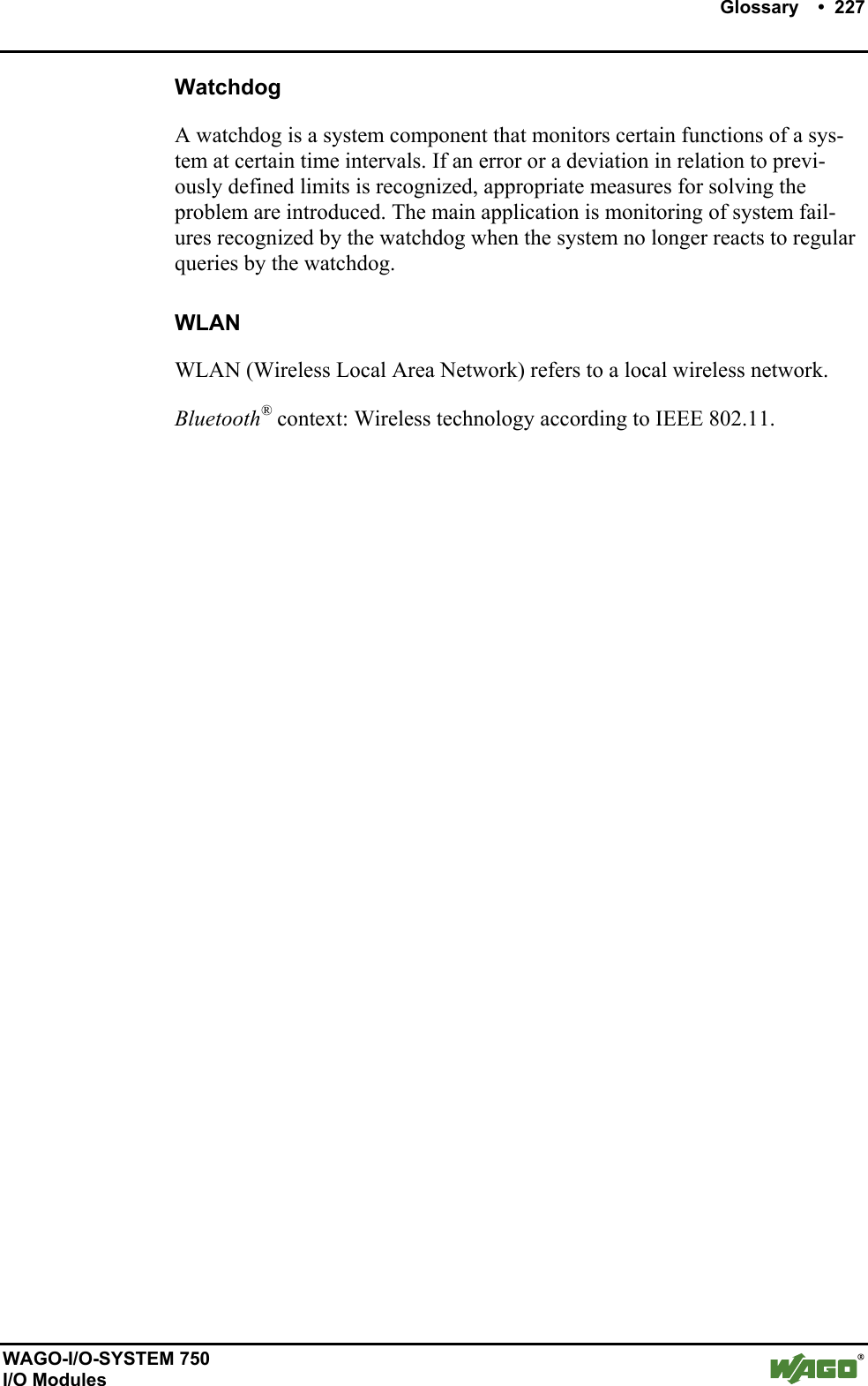
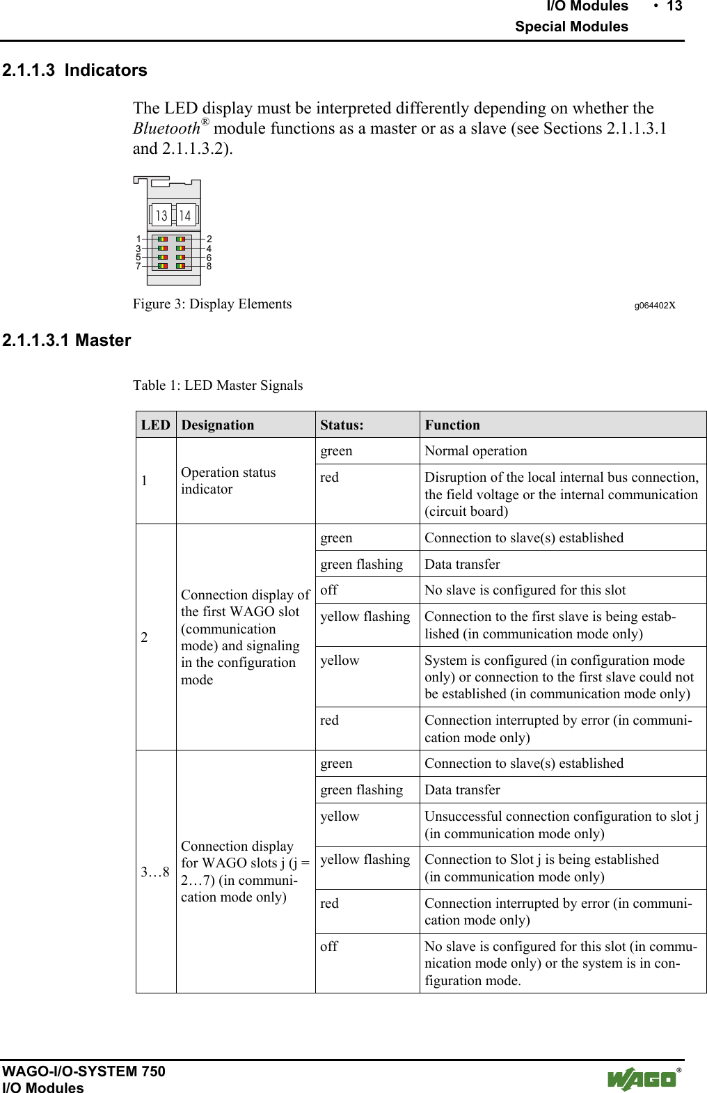
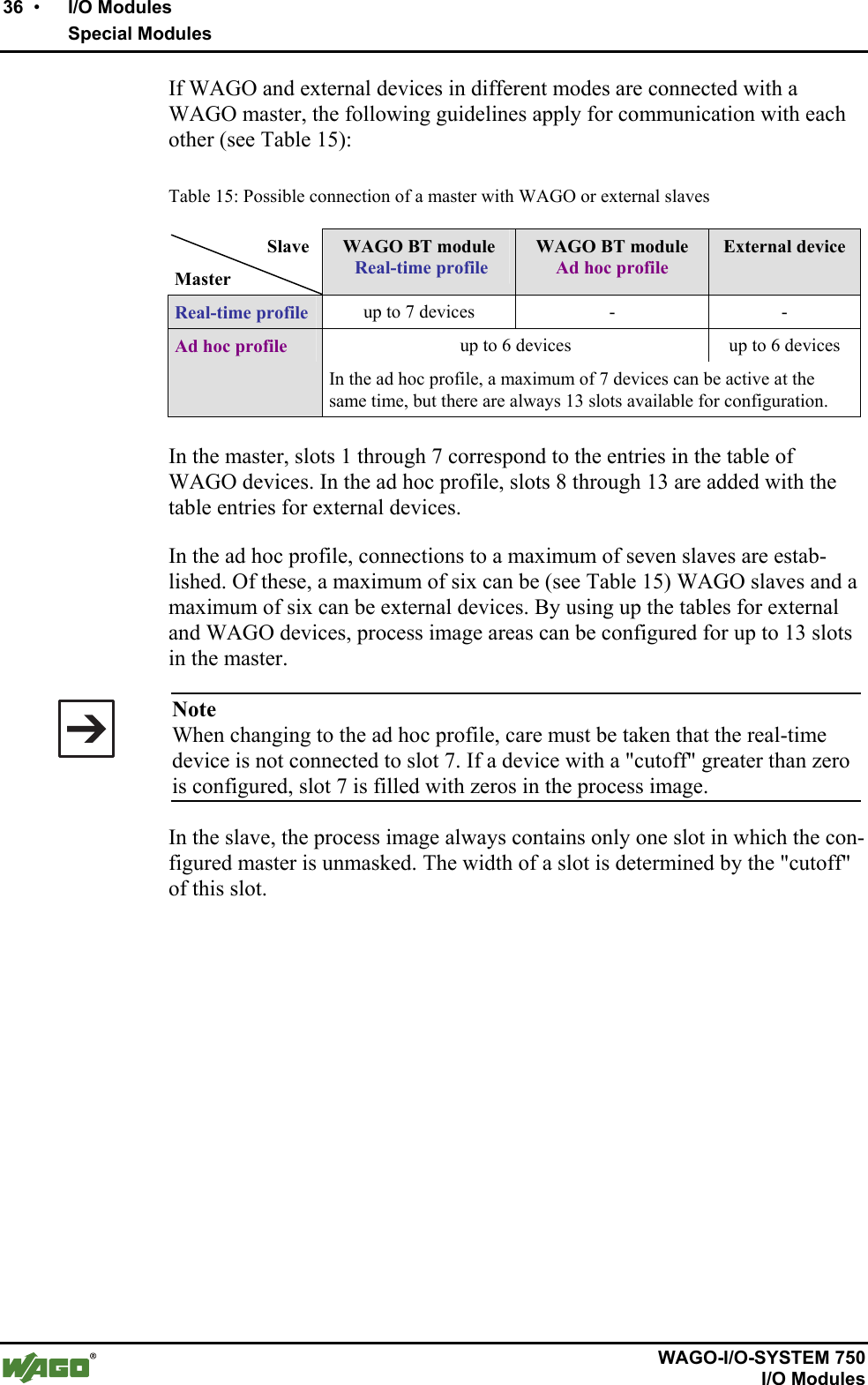
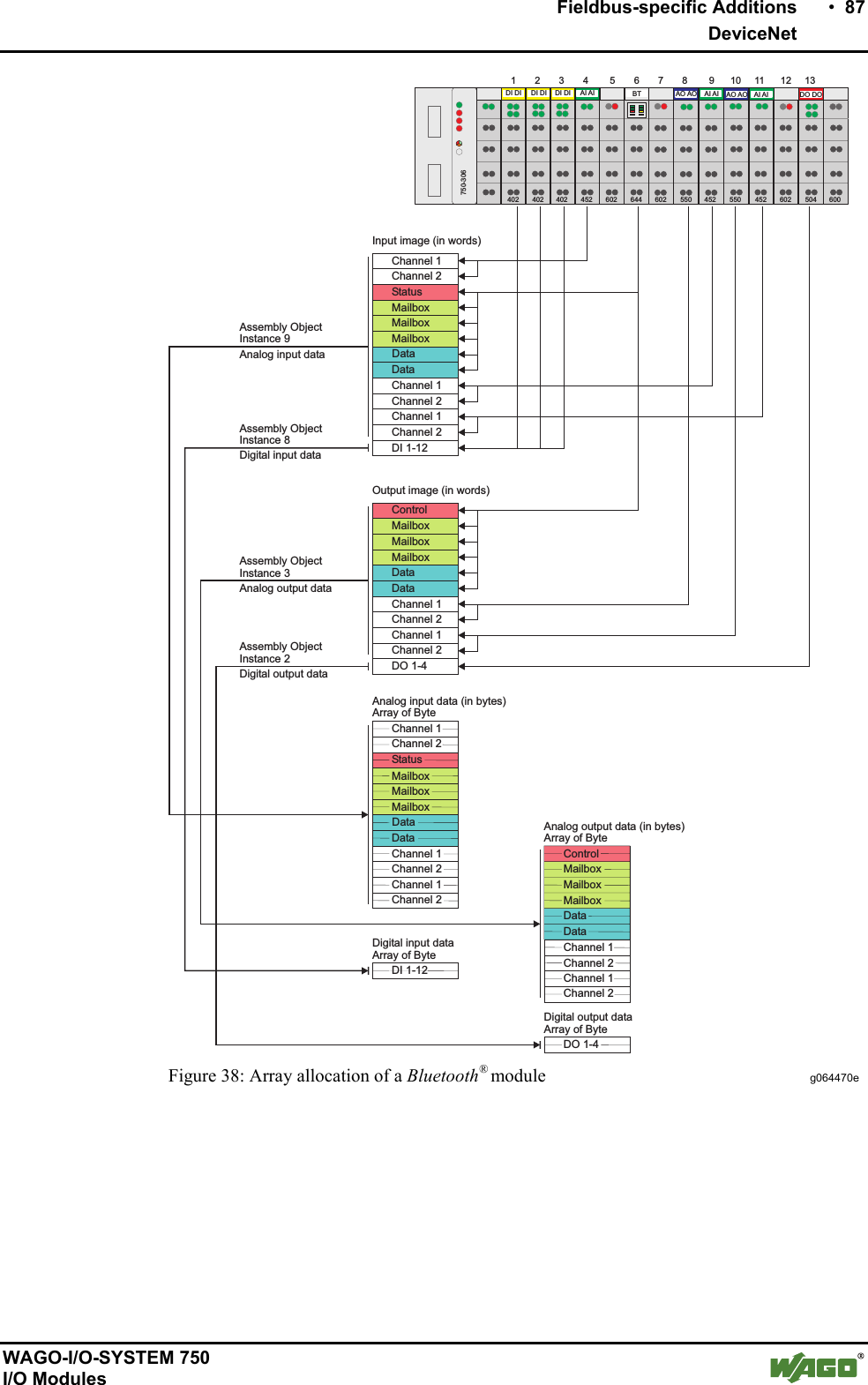
![22 • I/O Modules Special Modules WAGO-I/O-SYSTEM 750 I/O Modules 2.1.1.7.1 Time Required for Initialization Waiting times occur during the initialization of the module (see Table 5): Table 5: Waiting times during normal operation of the module Waiting times for Seconds Connecting to the first slave ~ 5 [1] Establishment of connection to a ready-to-receive slave 2-3 Successful establishment of connection by the master to another slave 2-3 [2] Unsuccessful attempt to connect to another slave 3-5 Inquiry up to 10.3 [3] [1] if the slave is ready-to-receive at the conclusion of the master's boot process [2] the master does not achieve a connection to the slave when attempted [3] shorter in more than 15 found devices 2.1.1.7.2 Configuration and Communication Mode The Bluetooth® module operates automatically in configuration mode during the first operation. If the communication mode with the real-time or ad hoc profile has already been selected via WAGO-I/O-CHECK, the module's mode will be changed to the respective profile. During startup of the module, the last configuration is the one loaded. If this is not correct; e.g., in the case of an invalid memory structure, the configuration is overwritten with the factory settings. Note The factory settings can also be reset using the mailbox command "SetFac-torySettings". The individual values for the factory settings can be found in Table 6. During initialization, the general error bit 26 is set in the status byte. This means that no mode has been received and there is no valid process data avail-able. LED 1 lights up red during initialization (duration approx. 5s). Once initialization is complete, the module takes on the last configured operat-ing mode, and LED 1 changes to green. During first operation (factory set-ting), the module will be in configuration mode following initialization. In configuration mode, the settings of the module can be configured according to the desired function, for example by using WAGO-I/O-CHECK. In this mode, the module can search for other Bluetooth® devices within reception range and is visible for queries.](https://usermanual.wiki/u-blox/WTB08/User-Guide-1066128-Page-22.png)
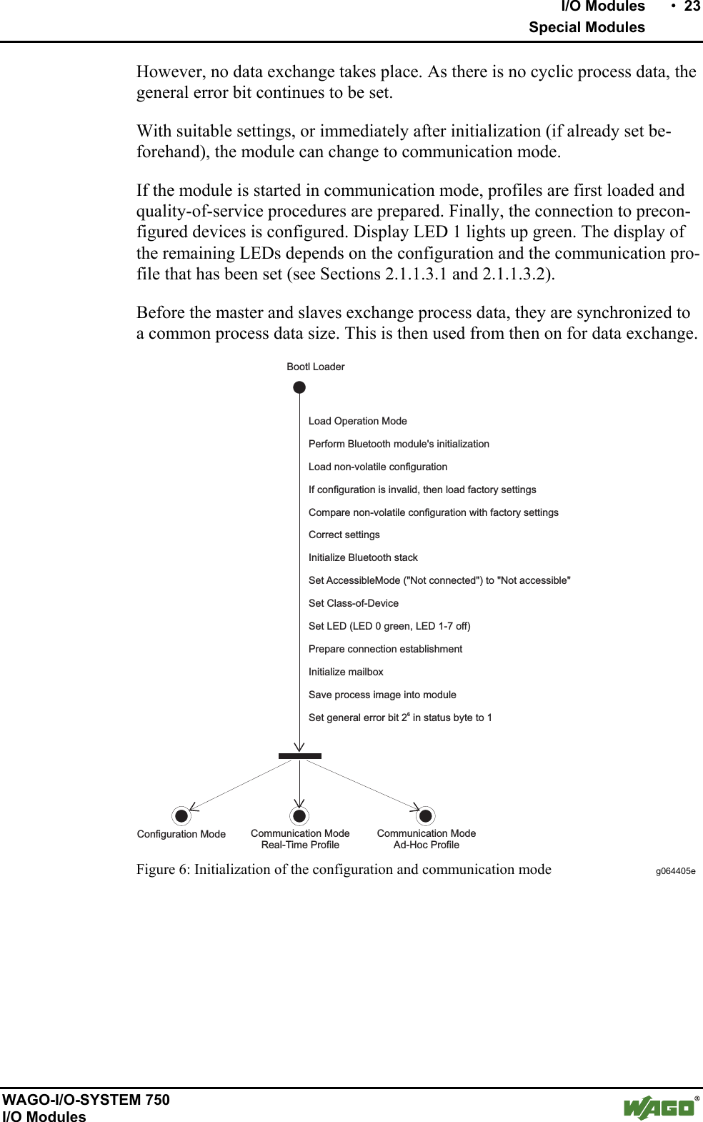
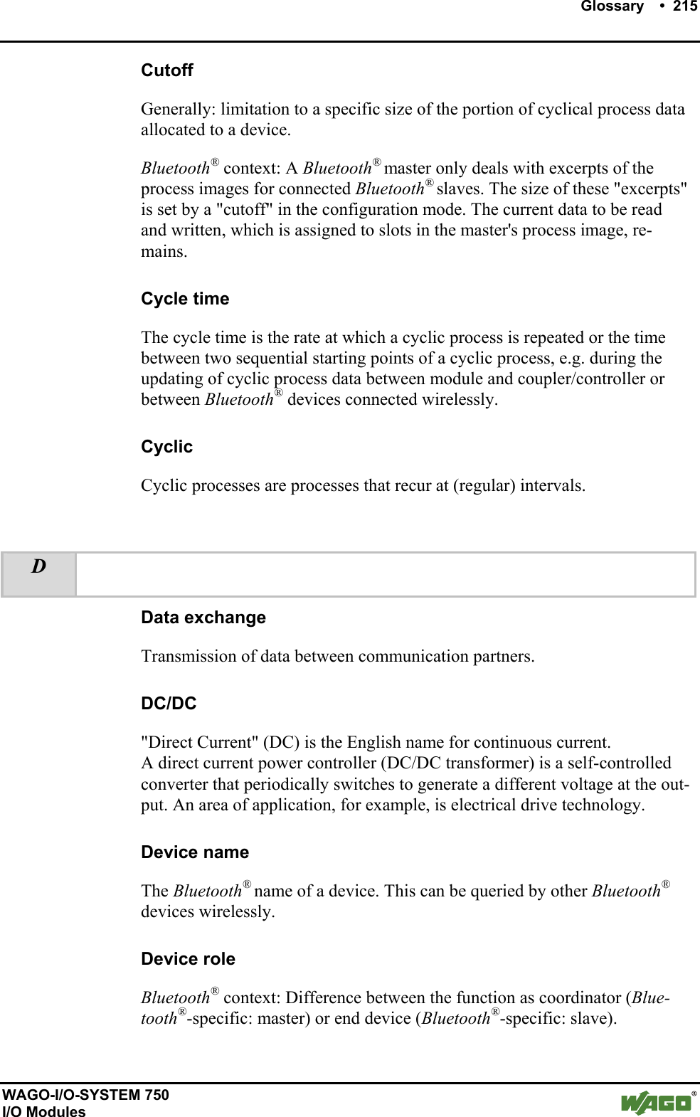
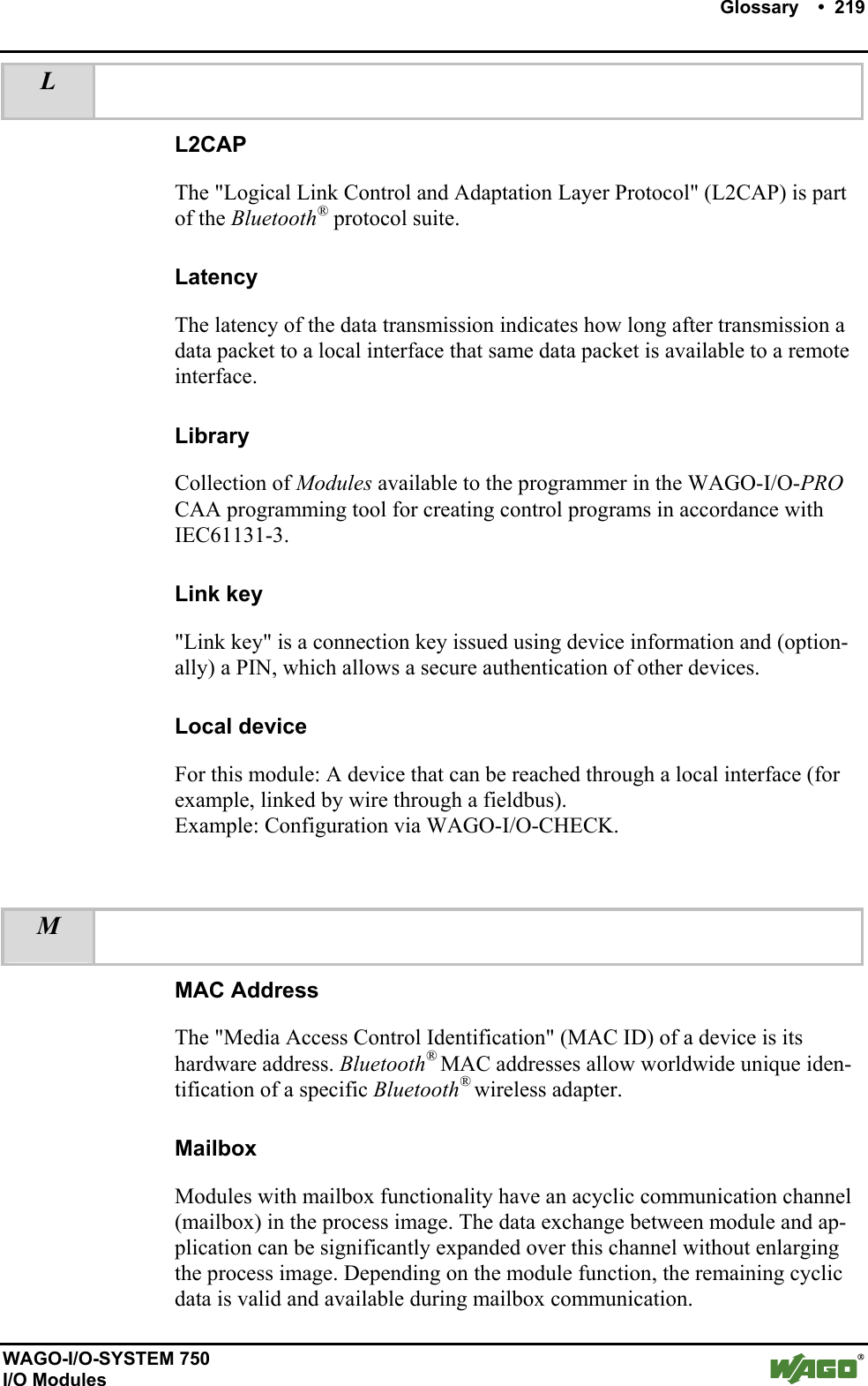
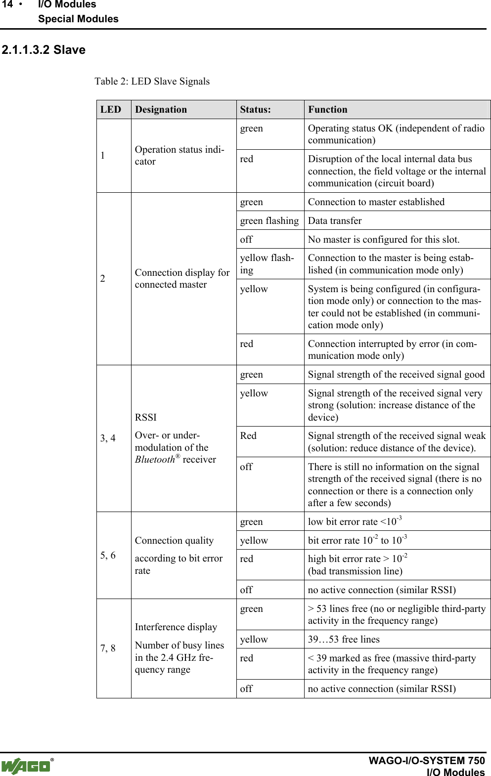
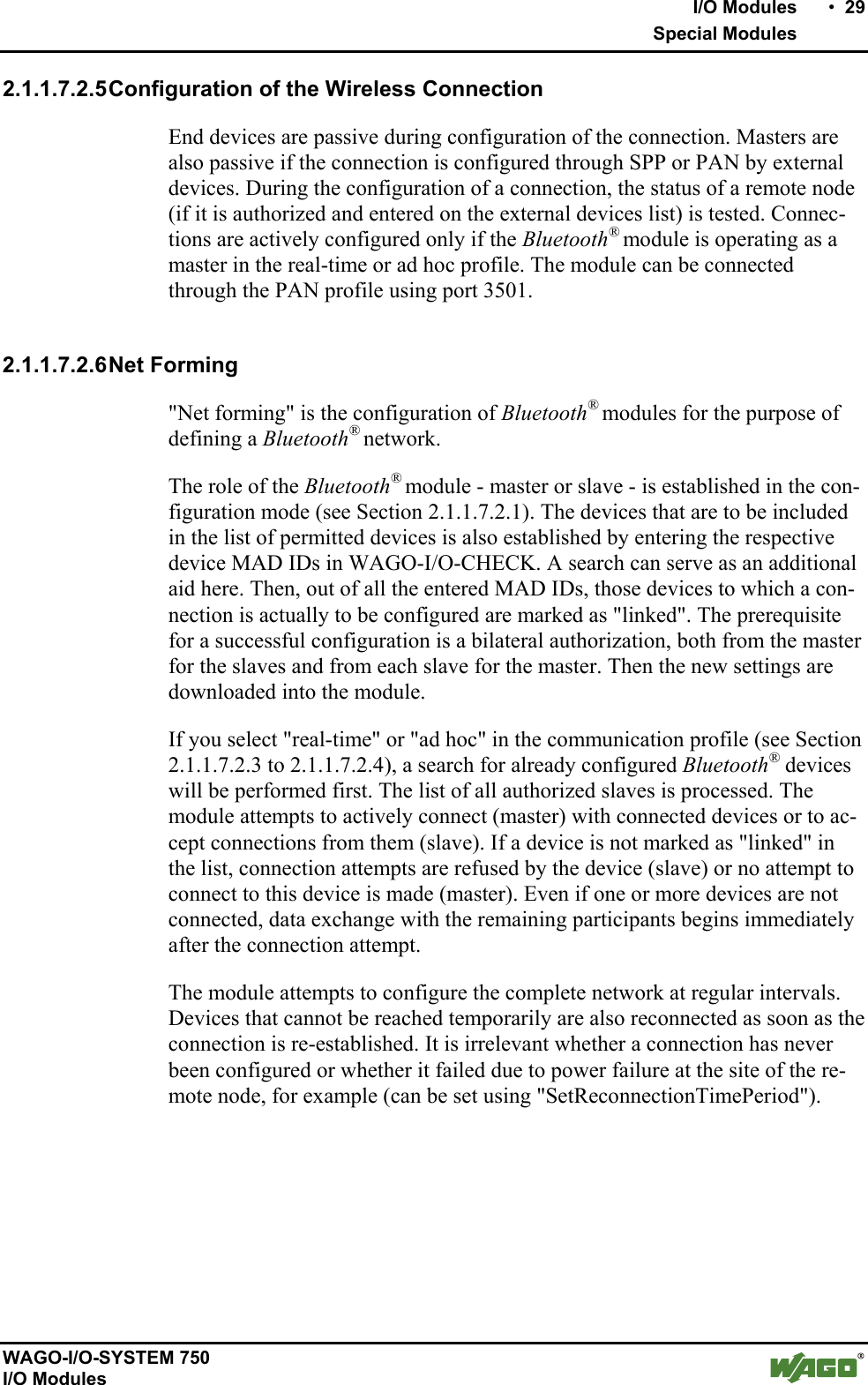
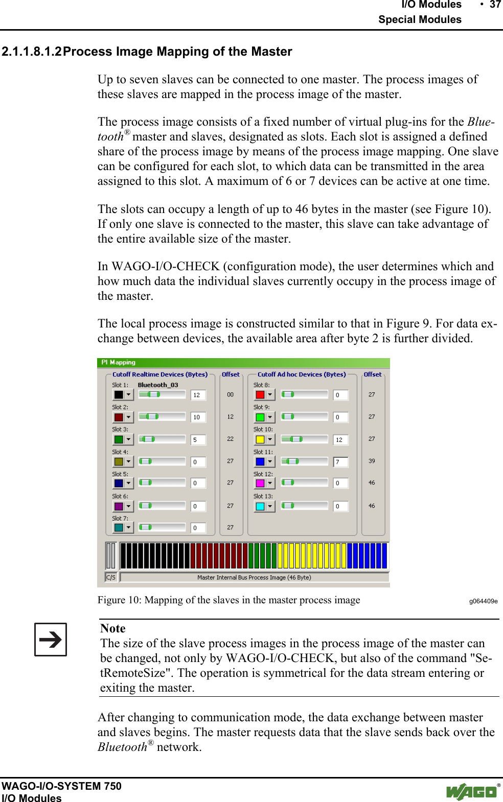
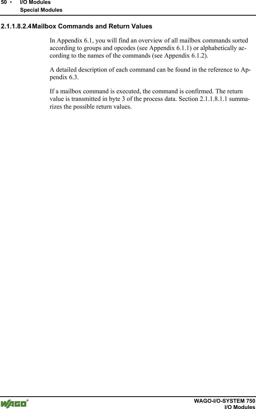
![28 • I/O Modules Special Modules WAGO-I/O-SYSTEM 750 I/O Modules Table 9: Configuration of the Bluetooth® Packet Channel name Length in bytesValue Description CHANNEL_SELECT 1 0000 0001 (0x01) Virtual channel selection, always 0x01 STATUS_FLAGS 1 0000 0000(0x00) Status bits, always 0x00 for external devices STATUS_DATA_SIZE 1 xxxx xxxx Data length in bytes, according to "cutoff" (see Section 2.1.1.8.1.2) DATA[1] 1 xxxx xxxx 1st byte of process data ... ... xxxx xxxx ... DATA[n] (=cutoff) 1 xxxx xxxx nth (last) byte of process data This header is automatically added in WAGO (see Figure 7). Bluetooth®Bluetooth®WAGO DeviceHeader is added and removed automaticallyDataExternal DeviceRadio transmissionRadio transmission01 00 DataCutofflength01 00 DataLocal dataHeader must becreated from the device01 00 DataCutofflengthDataDataC/S int Data01 00 DataControl/status byteare not transmittedHeader is addedautomaticallyControl/status byteare addedHeader is removedautomaticallyHeader is removedfrom the deviceLocal dataHeader must be added and removed from the deviceCutofflengthCutofflength Figure 7: Adding the header in data packets of external devices g064406e Note Missing data in the protocol header may lead to termination of the connec-tion. Therefore, prepend the 3-byte channel information (0x01 and 0x00 and field length) to the data to be transferred if you would like to send from an external device to a WAGO device. WAGO devices add the header automatically.](https://usermanual.wiki/u-blox/WTB08/User-Guide-1066128-Page-28.png)
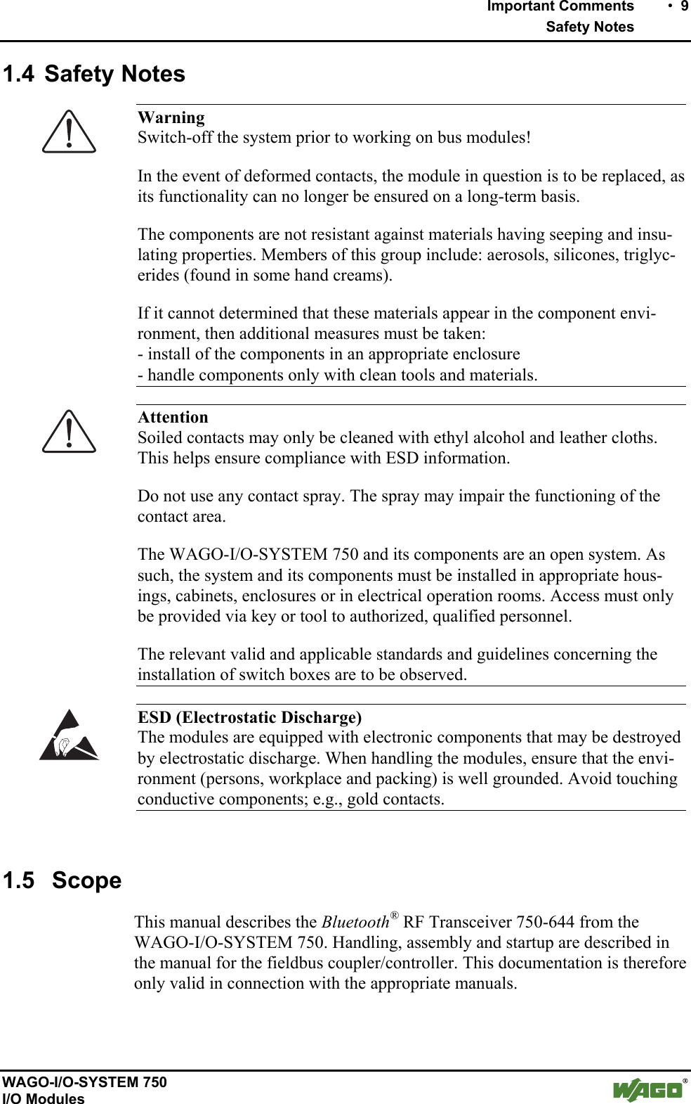
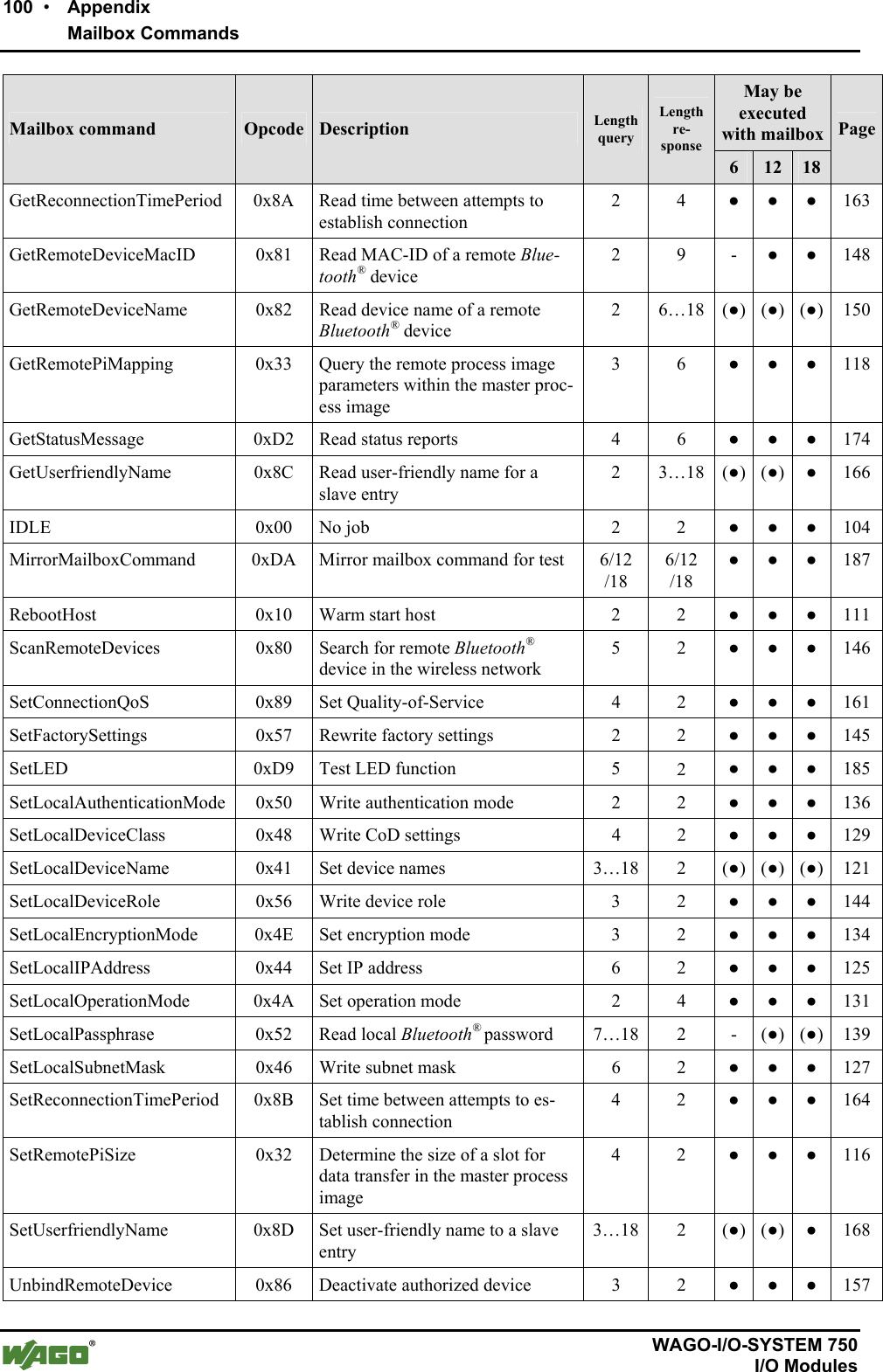
![48 • I/O Modules Special Modules WAGO-I/O-SYSTEM 750 I/O Modules 2.1.1.8.2.3 Access Procedure Unmasking the mailbox by setting bit 5 in the control byte is required for exe-cuting mailbox commands. The module confirms this by setting bit 5 in the status byte. In order to execute a mailbox command, query parameters and the opcode of the command must be written in the output process image. Since a change in the opcode and/or the toggle bit is a trigger for the processing of a command, the query parameters must be written into the output process image either at the same time or previously. The module confirms the processing of the command by inserting a response telegram in the mailbox area of the internal data bus input data. The response evaluation must occur at the same point at which the opcode and toggle bit are identical with the query contents; i.e., these are mirrored. The processing time in the module may require several bus cycles. Some special commands trigger a longer process (e.g., search for devices within range). For these commands, the module's response confirms that the process has begun. The results of longer lasting processes can be queried after completion by other commands. The toggle bit is necessary for executing two mailbox commands with the same opcode (but possibly differing parameters) one after the other. Note The use of mailbox commands implements a confirmed service. The module provides information via return value on the successful execution of the command or errors that occur. If errors occur, it may be that not all response bytes contain valid data. The following diagram (see Figure 17) describes the request and processing of a mailbox command. The process data are displayed as follow in this case: [ parameter 0-x | toggle | opcode | internal byte | control/status byte ] Initially, any process data may be present in the output and input process im-age. After entering the opcode and/or toggle bit, as well as switching the mail-box on using bit 25 in the control byte, the mailbox command is transmitted and a query is started. In the input process image, the query is received, proc-essed and confirmed with bit 25. This confirmation and the new process data are sent to the output process image. Here, the data is evaluated. The next command can be transmitted.](https://usermanual.wiki/u-blox/WTB08/User-Guide-1066128-Page-48.png)
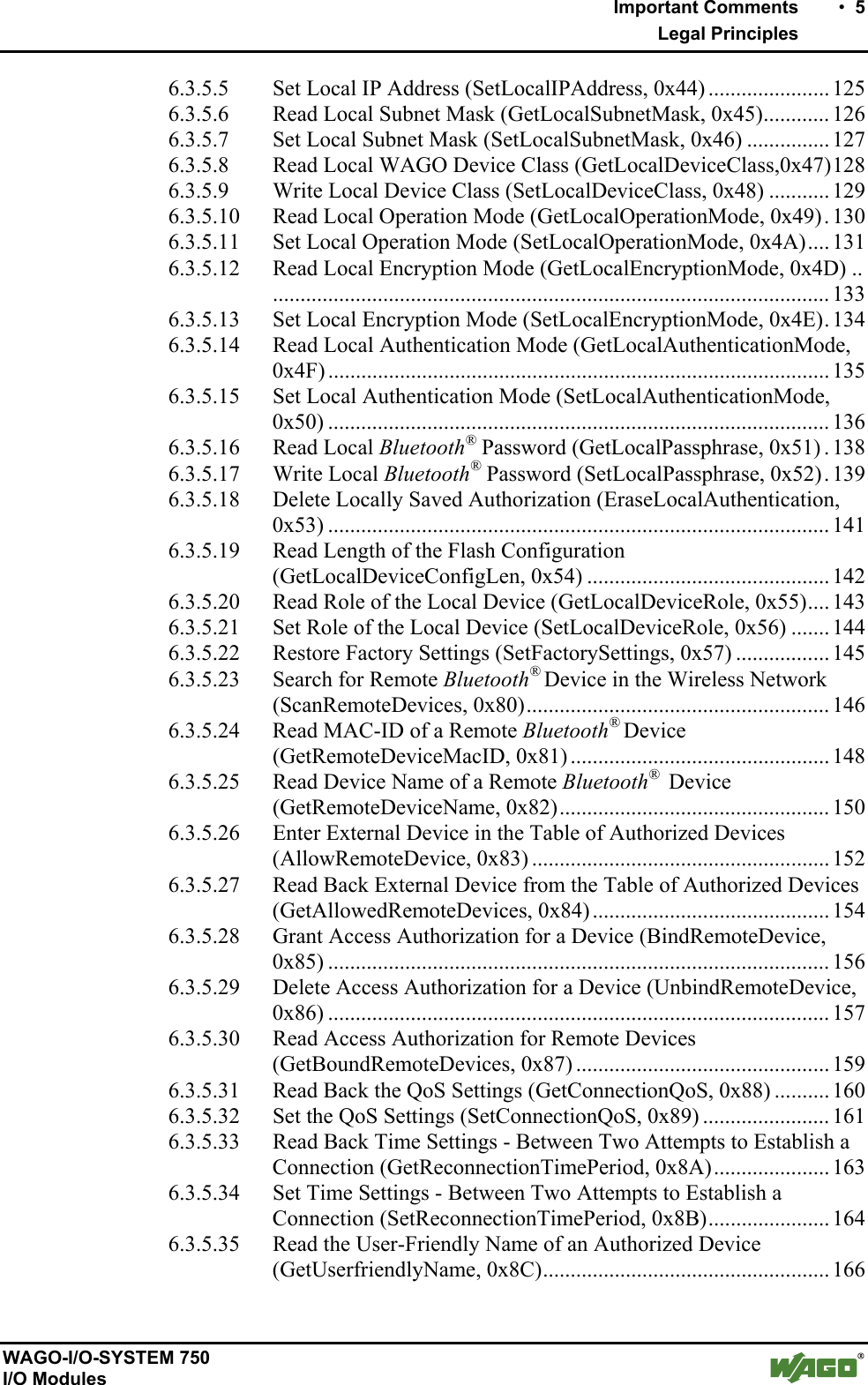
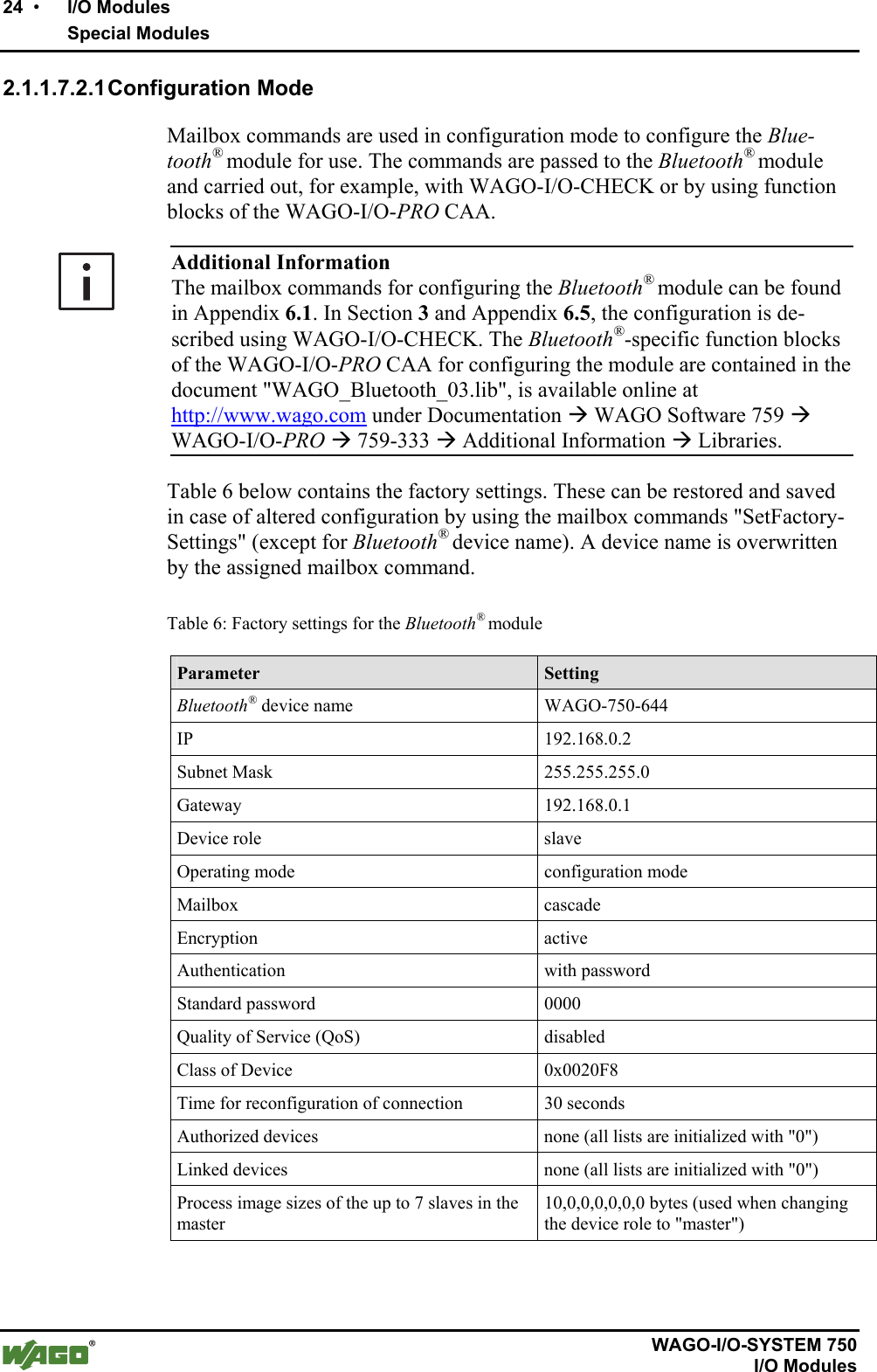
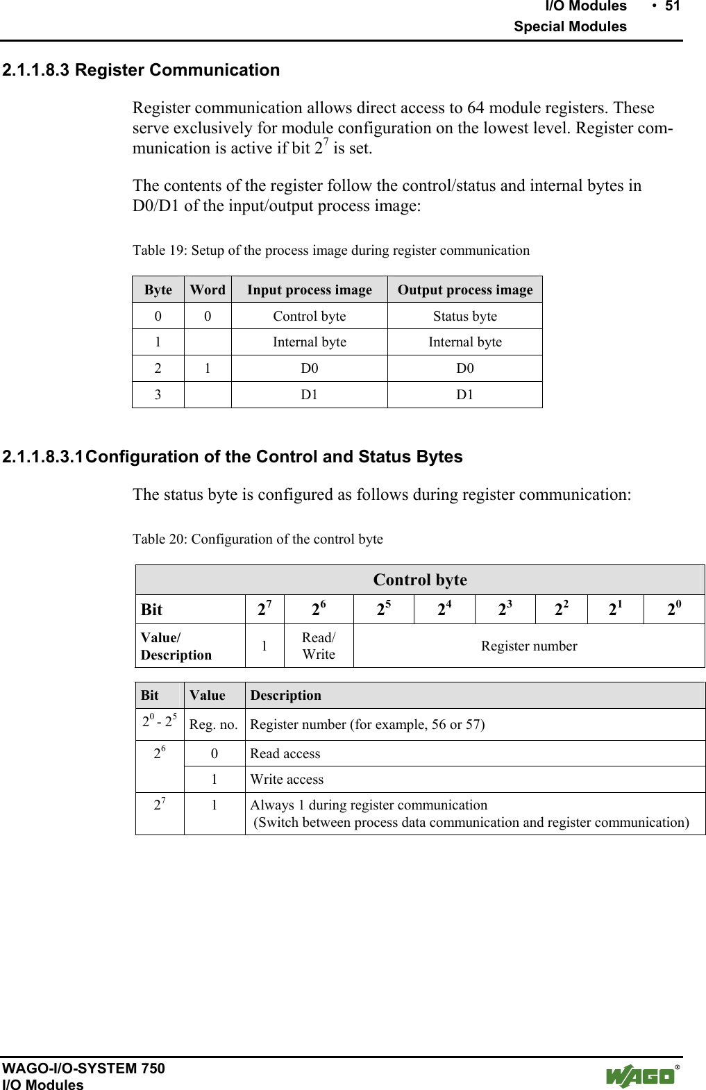
![I/O Modules • 49 Special Modules WAGO-I/O-SYSTEM 750 I/O Modules PIO Processing Times PII Cyclically updated process data [XX.XX.XX.XX.XX.XX.XX.XX.XX.XX].00.00 Cyclically updated process data [XX.XX.XX.XX.XX.XX.XX.XX.XX.XX].00.00 Switching on the mailbox, mailbox command IDLE (0x00) [XX.XX.XX.XX].[00.00.00.00].[00.00].00.20 Response to mailbox command IDLE (0x00) [XX.XX.XX.XX].[00.00.00.00].[00.00].00.60 Request for mailbox command GetLinkSignal-Strength (0xD7) [XX.XX.XX.XX].[00.00.00].[20].[00.D7].00.20 This queries the receive signal strength for the first slot. The mailbox includes: Opcode 0xD7 Toggle byte 0x00 Argument 0x20 (Slot 1) Filling byte 0x00 (for unused mailbox bytes) .. Response to mailbox command GetLinkSignal-Strength (0xD7) [XX.XX.XX.XX].[00.00.00].[1B].[00.D7].00.60 Response to the query: Opcode (mirrored) 0xD7 Toggle bit, return value 0, 0x00 Argument 0x1B (value of the signal strength of the queried slot) Filling byte 0x00 (for unused mailbox bytes) Request for mailbox command GetLinkSignal-Strength (0xD7) [XX.XX.XX.XX].[00.00.00].[28].[80.D7].00.20 This queries the receive signal strength with a false argument. The mailbox includes: Opcode 0xD7 Toggle byte 0x80 (toggle bit set to execute new command) Argument 0x28 (invalid) Filling byte 0x00 (for unused mailbox bytes) . Response to mailbox command GetLinkSignal-Strength (0xD7) [XX.XX.XX.XX].[00.00.00.00].[83.D7].00.60 Response to the query: Opcode (mirrored) 0xD7 Toggle bit, return value 1, 0x03 Argument No argument since invalid call up Filling byte 0x00 (for unused mailbox bytes) Since an invalid index was used with 0x28, there are no arguments in the response. Cyclically updated process data (mailbox masked) [XX.XX.XX.XX.XX.XX.XX.XX.XX.XX].00.00 Cyclically updated process data (mailbox masked) [XX.XX.XX.XX.XX.XX.XX.XX.XX.XX].00.00 Figure 17: Example of mailbox communication g064416d](https://usermanual.wiki/u-blox/WTB08/User-Guide-1066128-Page-49.png)
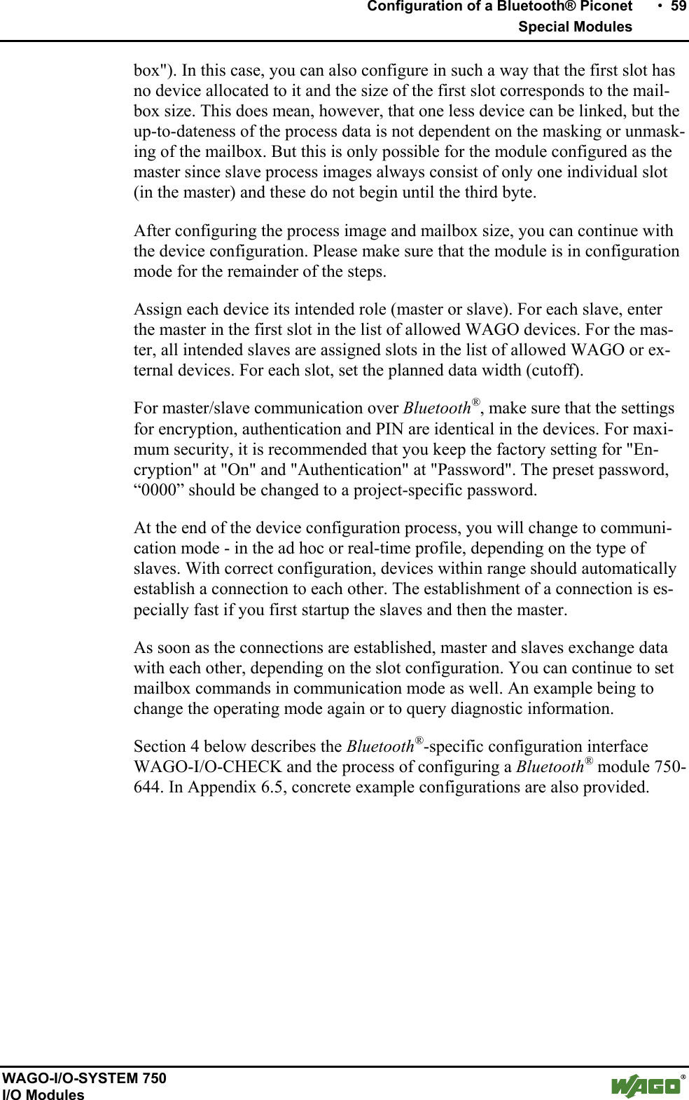
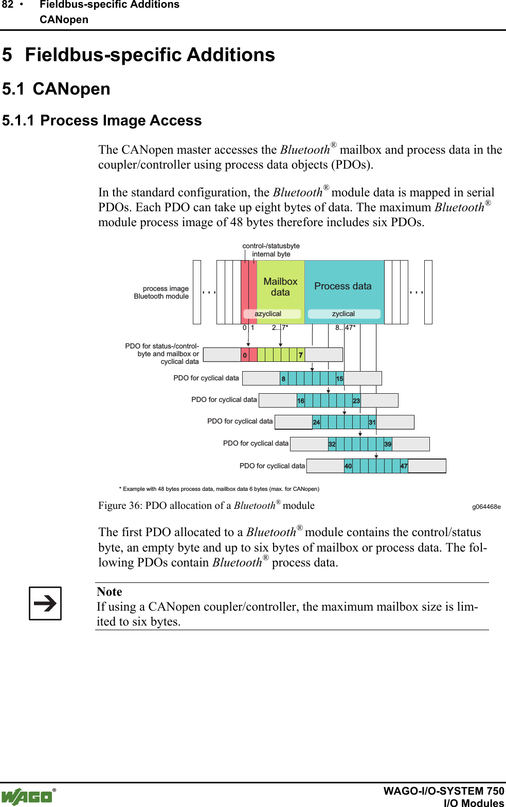
![58 • Configuration of a Bluetooth® Piconet Special Modules WAGO-I/O-SYSTEM 750 I/O Modules 3 Configuration of a Bluetooth® Piconet To configure a piconet, connect 2 to 8 Bluetooth® devices with each other. In doing so, there is some important framework data to consider: Is real-time or ad hoc communication beneficial for your application? Is the data that you wish to transmit time-critical data? Also important, how many WAGO Bluetooth® modules and how many exter-nal Bluetooth® modules are to communicate with each other: If only WAGO devices are to be connected with each other, you can connect one master with seven slaves. This only applies for the real-time profile, however. In the ad hoc profile, you can connect up to six WAGO slaves. If you also want to use external Bluetooth® devices in your piconet, choose the ad hoc profile. In this profile, seven WAGO devices and six external devices can be linked, but only a maximum of seven devices can actively exchange data at the same time. In preparation for configuration, note which Bluetooth® device will take over which role (master/slave), what the MAC addresses of the devices are and which communication profile is to be set (real-time/ad hoc). This makes the overview easier for you. These considerations will determine the allocation of the devices to available slots in the master process image. These are available for the data exchange. In a later step, you will determine the number of bytes (cutoff size) for each slot that should be available in the master process image for data exchange. Only the process data allocated to the slots will be transmitted wirelessly. Therefore, your configuration will work most efficiently if slave devices are set to the smallest possible process image size. The smallest possible process image size for a slave corresponds to the smallest setting for its process image size, which is the same or larger [2 + cutoff of the corresponding slot]. After drafting your configuration in the previous steps, you can now synchro-nize the device configurations to each other. To do this, first configure the process image and mailbox size. The mailbox size determines which mailbox commands can be executed. To configure with WAGO-I/O-CHECK or building blocks of the WAGO-I/O-PRO CAA, you can choose each available mailbox size independently of limi-tations of the fieldbus. For a successful configuration, a mailbox size of at least 12 bytes is necessary. If you want all diagnostic commands available to the full extent, set it for 18 bytes. If you are using a fieldbus over which less than 20 bytes per data element can be transmitted (e.g. CANopen), you should reduce the mailbox size again to an appropriate size after successfully com-pleting the device configuration. If you plan to use the mailbox during ongoing communication; e.g., for diag-nostic purposes, take note that when unmasking the mailbox, process data may be temporarily covered (see Section 2.1.1.8.2.1, "Aging of data by the mail-](https://usermanual.wiki/u-blox/WTB08/User-Guide-1066128-Page-58.png)
![62 • Tools for Configuring and Operating Configuring and Operating with WAGO-I/O-CHECK WAGO-I/O-SYSTEM 750 I/O Modules 4.1.1.1 Title Bar The position of the module within the node (as well as its name and item and version number) are displayed in the title bar of the parameterization dialog. 4.1.1.2 Symbol Bar The symbol bar in the Bluetooth® parameterization dialog contains the follow-ing buttons (see Figure 21): Figure 21: Buttons in the Bluetooth® parameterization dialog g064420e Table 24: Buttons in the Bluetooth® parameterization dialog g064421e-30e Button Description [Close] Closes the active window. If you have changed settings, you will be asked to accept the values in the I/O module. [Open] Opens window to select a parameter file. Device settings are read from the pa-rameter file and transferred to the connected I/O module. [Save] Opens a window to select a parameter file. The device settings are saved in the parameter file. [Read] Reads the current settings from the connected I/O module and displays them in this window. [Write] Transfers the settings displayed in this window to the connected I/O module. [Default] Overwrites the locally saved configuration with the factory settings. [Restart] Restarts the host controller. Attention: All wireless connections are broken off. [Flash] Writes the current configuration of the host controller to the flash memory and restarts it. Attention: All wireless connections are broken off. [Data Frame] Sets process size and mailbox size. [Help] Displays help for this window.](https://usermanual.wiki/u-blox/WTB08/User-Guide-1066128-Page-62.png)
![Tools for Configuring and Operating • 63 Configuring and Operating with WAGO-I/O-CHECK WAGO-I/O-SYSTEM 750 I/O Modules 4.1.1.3 Navigation You can toggel between the different configuration areas of the module by us-ing the navigation on the left side of the screen (see Figure 22). Figure 22: Navigation between configuration areas g064431e Choose between the following menu items (see Table 25): Table 25: Navigation between configuration areas g064432e-36e Menu item Description [Settings] Opens a page with general module parameters such as device name, MAC address, device role, etc. These parameters can be altered here and loaded to the module (see Section 4.1.1.5.1, "Settings"). [Net Forming] Opens a page with device lists. Here, configured and bound devices within range are displayed with MAC address and name and configured (see Section 4.1.1.5.2, "Net Forming"). [PI Mapping] Opens a page for the allocation of slave process data to slots in the master (see Section 4.1.1.5.3, "PI Mapping"). [Block Transfer] Opens a page for viewing the process data during uploading and downloading. The menu entry "Block transfer" is only displayed in the configuration mode (see Section 4.1.1.5.4, "Block Transfer"). [Diagnostics] Opens a page with comprehensive diagnostic information on the status of the module and the network as well as the connection quality (see Section 4.1.1.5.5, "Diagnostics"). The menu entry "Diagnostics" is only displayed in the communication mode.](https://usermanual.wiki/u-blox/WTB08/User-Guide-1066128-Page-63.png)
![64 • Tools for Configuring and Operating Configuring and Operating with WAGO-I/O-CHECK WAGO-I/O-SYSTEM 750 I/O Modules 4.1.1.4 Mode Assignment Device Role is displayed in the top area, indicating whether the currently con-figured module is a master or a slave. The lower area, Operation Mode is used to assign the mode to the locally connected module. Using the buttons, choose whether the module is to be op-erated in either the configuration or communication mode (real-time or ad hoc profile) (see Figure 23). Figure 23: Changing mode g064437e Choose between the following menu items: Table 26: Navigation between configuration pages g064438e-42e Menu item Description "Slave" or "Master" Displays the currently assigned device role of the local module. [Configuration] Switches the locally connected module to the configuration mode. [Communication (Ad-hoc)] Switches the locally connected module to the communication mode (ad hoc profile). [Communication (Realtime)] Switches the locally connected module to the communication mode (real-time profile).](https://usermanual.wiki/u-blox/WTB08/User-Guide-1066128-Page-64.png)
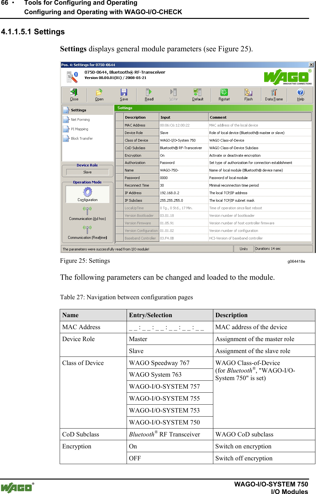
![Tools for Configuring and Operating • 65 Configuring and Operating with WAGO-I/O-CHECK WAGO-I/O-SYSTEM 750 I/O Modules 4.1.1.5 Parameterization Area In the parameterization area, the Bluetooth® module is configured and pre-pared for communication. This is described in further detail in the following sections. Changing and saving data To change settings in the Bluetooth® module, adjust the values displayed in the parameterization area. Altered settings are labeled with a change symbol . This indicates that the displayed values are no longer the same as the origi-nally queried values of the module. To transfer the new values to the module, click on the [Write] button. The change symbols will disappear. In this writing process, the values of the module are first temporarily saved so that clicking on [Restart] can delete the changes again. In this case, you should update the graphic display of the values after restart by clicking on [Read]. To save transferred value changes permanently (flash process) without chang-ing the operating mode, click on [Flash]. You may also change the module to another operating mode. When you do this, transferred changes are automati-cally and permanently saved. For example, you can change the module over to the communication operating mode (real-time) after completing configuration under Net Forming. This will cause the altered configuration to be saved, and the module attempts immediately to exchange data with the configured partner devices. WAGO-I/O-CHECKBluetooth®Preview for module's settingsMemory of module's settings (non-volatile)Buffer for new settings (volatile)WAGO Module[Save] [Read] or openthe dialog window[Flash] or change of operation mode(when the configuration is completed)Module's start-upor restart Figure 24: Saving the configuration g064471e](https://usermanual.wiki/u-blox/WTB08/User-Guide-1066128-Page-65.png)
![68 • Tools for Configuring and Operating Configuring and Operating with WAGO-I/O-CHECK WAGO-I/O-SYSTEM 750 I/O Modules 4.1.1.5.2 Net Forming "Net Forming" refers to the configuration of the Bluetooth® network. On the "net forming" side, devices are manually entered or automatically sought and bound for later communication. Figure 26: Net forming g064443e On the left side, all devices within range are displayed. You update the list by clicking on the [Search] button. Depending on the option selected, you can limit the search for devices. The Class-of-Device (CoD) is used as a criterion for filtering search results. Select All to search for any Bluetooth® devices within range in the environ-ment. Select WAGO 750 to search for all WAGO devices of the model series 750 within range.](https://usermanual.wiki/u-blox/WTB08/User-Guide-1066128-Page-68.png)
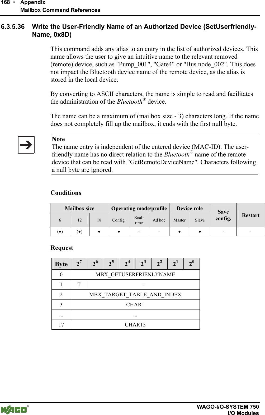
![Tools for Configuring and Operating • 69 Configuring and Operating with WAGO-I/O-CHECK WAGO-I/O-SYSTEM 750 I/O Modules Select Other to manually enter which CoD should be used to filter the search results (see Figure 27). Figure 27: Filter according to device classes g064489e To the right on the "net forming" page, the configured devices are displayed in two lists. The upper list contains WAGO devices using the real-time profile. The lower list contains both WAGO and/or external devices using the ad hoc profile. Selected devices within range are added to the real-time or ad hoc list by using the [>>] button. MAC addresses or device names can also be moved to the ad hoc or real-time list by drag & drop from the list of devices within range. Selected devices are deleted from the real-time or ad hoc list using the [<<] button. Deleting the device is also possible by double-clicking on the respec-tive MAC address. The tables on the Net forming page are filled as follows: Table 28: Table identifiers in "Net forming" Name Entry/Selection Description IS _ _ Device ID for devices within range MAC Address _ _ : _ _ : _ _ : _ _ : _ _ : _ _ MAC address of the device Device name ASCII characters Device name (cannot be changed) Slot _ Slot number of allocated device UserFriendlyName ASCII characters Name assigned to a slot (can be changed) Yes Bind device ("Yes") Bind No Do not bind device ("No") Note Remember when assigning a "UserFriendlyName", you must display the en-tire length of the name; a mailbox size of 18 bytes is necessary. With a smaller mailbox setting, the full name is actually displayed within WAGO-I/O-CHECK, but not completely saved, so when the name is read back from the module, not all the characters are displayed.](https://usermanual.wiki/u-blox/WTB08/User-Guide-1066128-Page-69.png)
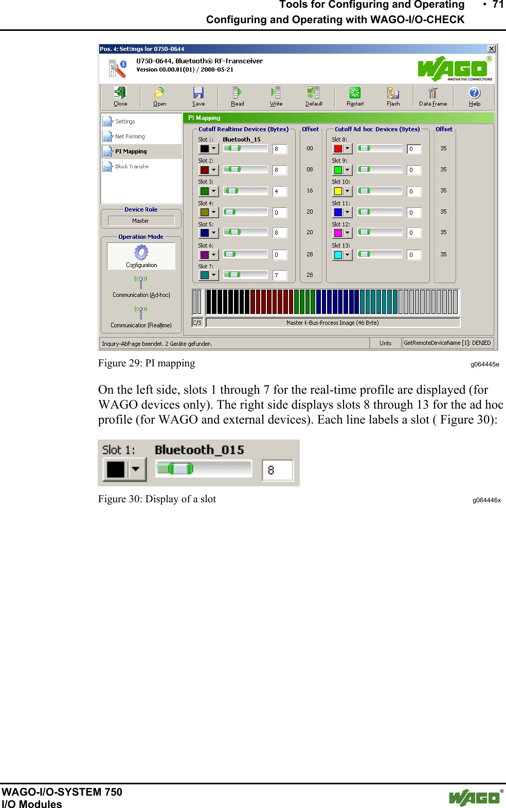
![70 • Tools for Configuring and Operating Configuring and Operating with WAGO-I/O-CHECK WAGO-I/O-SYSTEM 750 I/O Modules 4.1.1.5.3 PI Mapping To undertake settings on the "PI mapping" (process image mapping) page, the process image size of the master must first be set. Use the [Data Frame] button in the symbol bar to open the dialog for entering the process image and mailbox sizes (see Figure 28). Figure 28: Determine data framework g064444e The following settings are possible (see Table 29): Table 29: Determine data framework Toggle field Settings Process image size 12 bytes, 24 bytes, 48 bytes* Mailbox size 6 bytes, 12 bytes, 18 bytes* * Standard setting Button Description [Apply] Transfers the altered parameters to the module's permanent memory. A software reset is conducted so that the changes take effect. The dialog remains open. [Default] Selects the standard setting for this module. Then transfer the parameters to the permanent memory of the module by using the [Apply] button. [Close] Ends the parameterization dialog without transferring any altered pa-rameters to the permanent memory of the module. Note Please note that the structure of the process image changes when the process im-age size or mailbox size is changed. Therefore, changes in the configuration of the superordinate control may be necessary. On the "PI mapping" page, the slave process data is allocated to the slots in the master (see Figure 29). Up to 46 bytes of the process image are available for this purpose (depending on which process image size was set in the "Data framework" dialog). The control/status byte and internal byte are not taken into consideration here.](https://usermanual.wiki/u-blox/WTB08/User-Guide-1066128-Page-70.png)
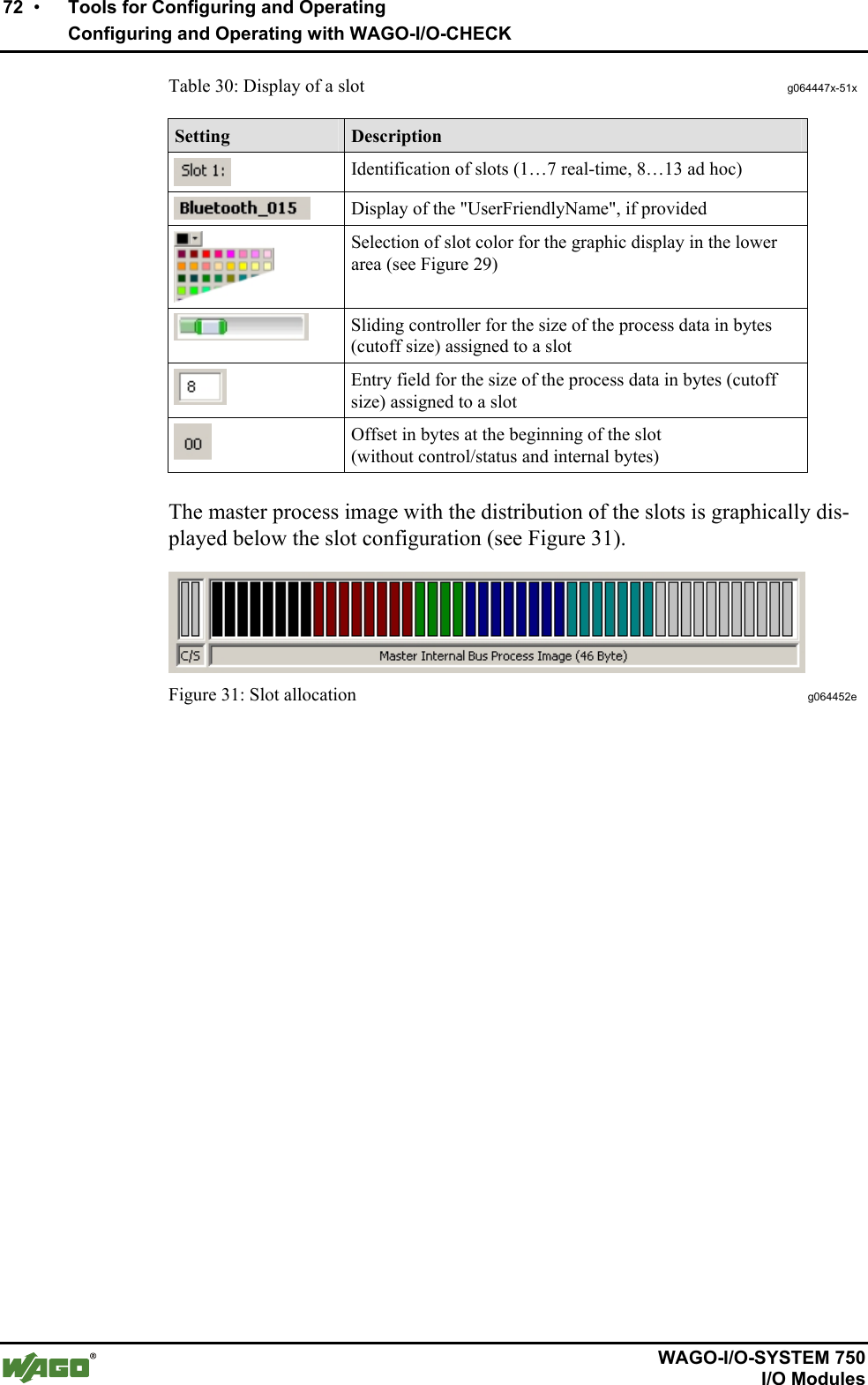
![Tools for Configuring and Operating • 73 Configuring and Operating with WAGO-I/O-CHECK WAGO-I/O-SYSTEM 750 I/O Modules 4.1.1.5.4 Block Transfer This page displays the configuration block during uploading and downloading of the process data (see Figure 32). The menu item Block Transfer is only visible in the configuration mode. Figure 32: Block transfer g064453e Choose between the following menu items: Table 31: Block transfer g064454e-58e Menu item Description Upload v [Configuration] Displays the configuration transferred from the module to the application. [Search Results] Displays the list of MAC addresses found during a search. [Local Name] Displays the complete local name of the module (in menu item "Settings", the name may be incomplete due to insufficient mailbox size). [Password] Loads the set password. [Remote Name] Displays the device names of the connected modules. By entering an ID (see page on Net forming), the device name of a special Bluetooth® device is displayed.](https://usermanual.wiki/u-blox/WTB08/User-Guide-1066128-Page-73.png)
![74 • Tools for Configuring and Operating Configuring and Operating with WAGO-I/O-CHECK WAGO-I/O-SYSTEM 750 I/O Modules Download [Configuration] Writes the configuration to the module. [Local Name] Writes the local name to the module. The name can be entered in the entry field. [Password] Writes the password in the locally connected module. The password can be entered in the entry field. 4.1.1.5.5 Diagnostics This page displays diagnostic information on the module status, the network and the quality of the connection (see Figure 33). The menu item Diagnostics is only visible in the communication mode. Figure 33: Diagnostics g064459e](https://usermanual.wiki/u-blox/WTB08/User-Guide-1066128-Page-74.png)
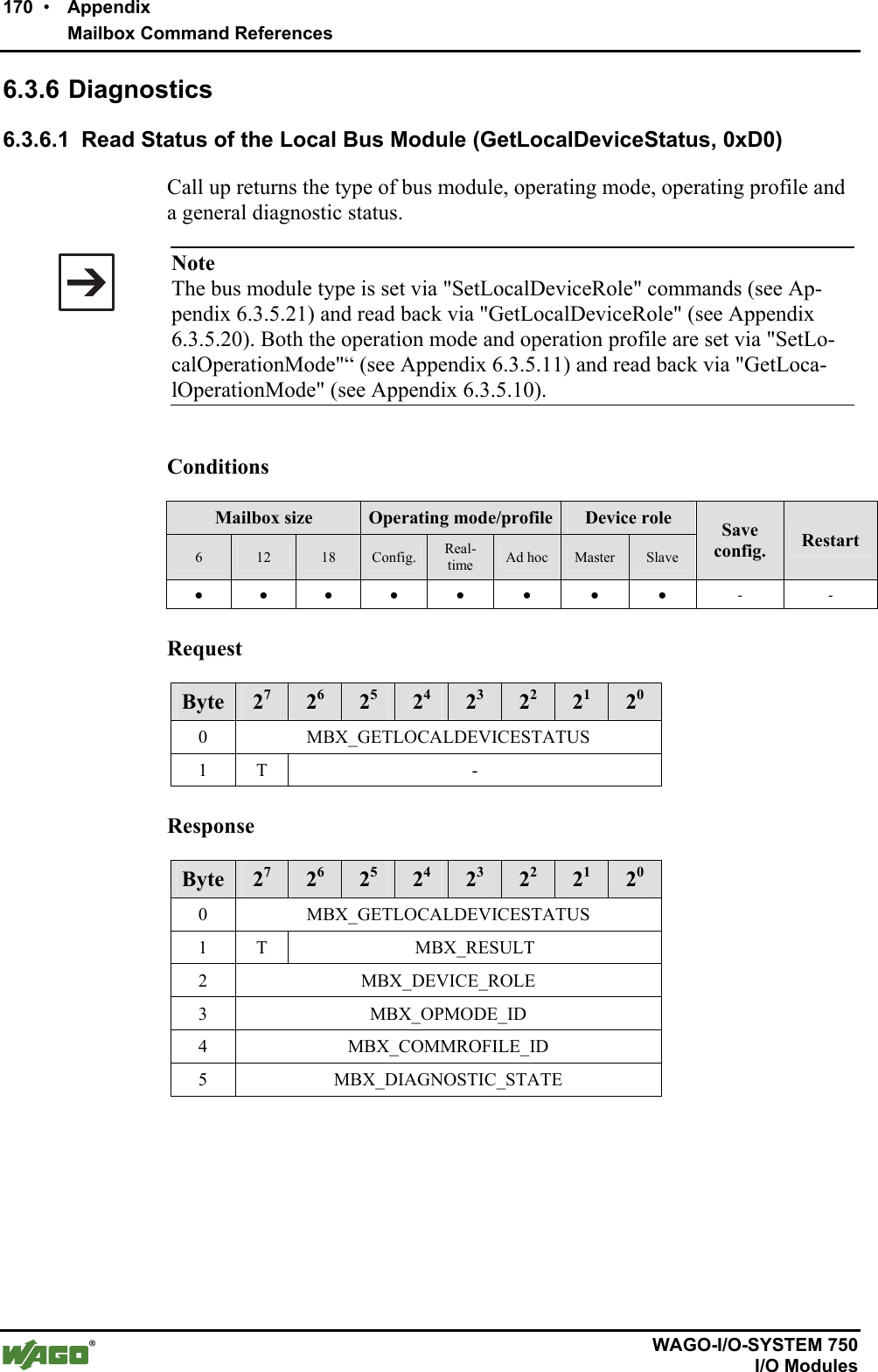
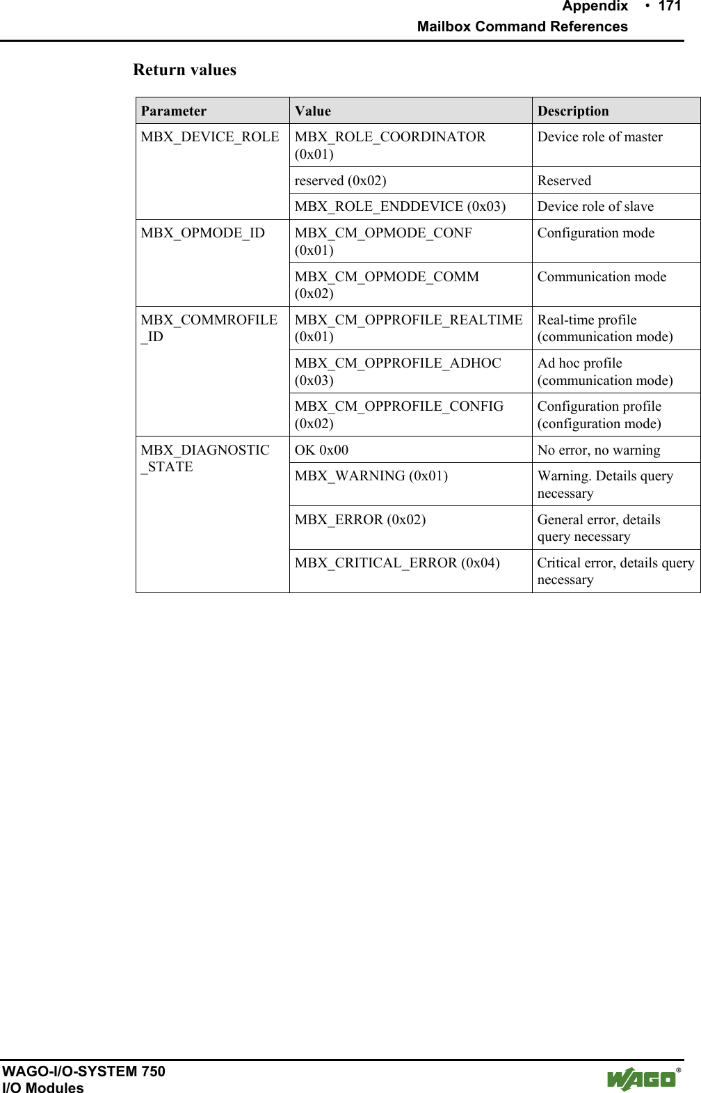
![Tools for Configuring and Operating • 75 Configuring and Operating with WAGO-I/O-CHECK WAGO-I/O-SYSTEM 750 I/O Modules The following displays are summarized under the header "Status" (see Table 32): Table 32: General status display Status Value Description Slave Device takes over the role of "slave" Device Role Master Device takes over the role of "master" (see also Appendix 6.3.5.20, "GetLocalDeviceRole") Operating Mode Communication Device is in communication mode (see also Appendix 6.3.3.2, "GetLocalOperationMode") Real-time profile Device is in the communication profile "real-time" Communication Profile Ad hoc profile Device is in the communication profile "ad hoc" Ok No warnings/errors Warning Warning Error General error Diagnostic State Critical defect Critical error (for details see Appendix 6.3.6.1, "GetLo-calDeviceStatus") Ok Configured network is established. Inconsistent Not all configured connections are established. Network Status Defective Configured network is (still) not established. (for details see Appendix 6.3.6.2, GetNetworkStatus) [Start Diagnostics] Start value monitoring [Stop Diagnostics] End value monitoring Under "Channel monitor", the transmission quality for each slot is displayed (see Table 33): Table 33: Status of transmission channel Status Value Description Slot No. Slot _ Slot Number Yes Connected No Not connected Connected No No device configured for this slot 0 % No bit error occurred 0.1…10% Some bit errors occurred Bit Error Rate > 10% High bit error rate](https://usermanual.wiki/u-blox/WTB08/User-Guide-1066128-Page-75.png)
![Tools for Configuring and Operating • 77 Configuring and Operating with WAGO-I/O-CHECK WAGO-I/O-SYSTEM 750 I/O Modules Object Groups Status * Ok Time monitoring Watchdog Ok Process image is defective Process image A remote mailbox is active Ok Interruption in SPI communication SPI is overloaded Intersystem communica-tion Error in the mailbox communication Ok Configuration altered Configuration Error in the network configuration * The meaning of the individual status reports can be found in Appendix 6.3.6.3. You can query the status with the set parameter by using the [Execute] button. 4.1.1.6 Status Display Status reports are given in the status display in the lower area of the parame-terization dialog. The display varies depending on the page accessed: Settings, Net forming, PI Mapping, Block Transfer and Diagnostics. Figure 35: Status display g064460e](https://usermanual.wiki/u-blox/WTB08/User-Guide-1066128-Page-77.png)
![78 • Tools for Configuring and Operating Configuring the Bluetooth® Module 750-644 WAGO-I/O-SYSTEM 750 I/O Modules 4.2 Configuring the Bluetooth® Module 750-644 In order to work with the Bluetooth® module 750-644, you must first set up the communication connection to your node. Then read the node configuration and select the desired module in the navigation or node view. Next, set the necessary process data and mailbox size in the parameterization dialog. After that, you can set the desired operating mode for the master in the process data dialog or select a slave for further processing from the list of slave addresses. Use the diagnostic function to eliminate configuration errors. 4.2.1 Setting the Bluetooth® Process Data and Mailbox Size If the parameterization dialog is not open, select Settings in the context menu of the selected module (node view or navigation). Using the [Data Frame] button in the symbol bar, open a dialog in which you establish the size of the process image in the internal data bus 12, 24 or 48 bytes. Choose 6, 12 or 18 bytes as the mailbox size. Note The available combinations of possible selections correspond to the configu-rations projectable by PROFIBUS or CANopen type files. To display the standard values for the module, press the [Default] button. The displayed values can then be changed. Transfer the set values to the permanent memory of the module by pressing the [Apply] button; exit the dialog by pressing [Close]. 4.2.2 Setting the Mode If the parameterization dialog is not open, select Settings in the context menu of the selected module (node view or navigation). The area Device Role displays whether the module is configured as master or slave. Under that, in the Operating mode area are three buttons: [Configura-tion], [Communication (Ad-hoc)] and [Communication (Realtime)]. Press one of these buttons to transfer the module to the respective mode or respec-tive profile. No explicit writing to the module is necessary.](https://usermanual.wiki/u-blox/WTB08/User-Guide-1066128-Page-78.png)
![Tools for Configuring and Operating • 79 Configuring the Bluetooth® Module 750-644 WAGO-I/O-SYSTEM 750 I/O Modules 4.2.3 Role Assignment (Master/Slave) The Bluetooth® module can be configured as either master or slave. Choose Settings in the context menu of the selected module (node view or navigation) to open the parameterization dialog. In the navigation to the left, choose Set-tings. Click in the field to the right beside Device Role. In the dropdown menu, select "master" to configure the module as a master or "slave" to trans-fer the role of slave to the module. Click on the [Write] button in the toolbar to assign the new role to the mod-ule. 4.2.4 Search for and Display Devices within Range Choose Settings in the context menu of the selected module (node view or navigation) to open the parameterization dialog. Choose Net Forming in the navigation bar. Choose the option All in the area Search for devices within range and click on the [Search] button. The network is searched for Blue-tooth® devices within range. Found devices are displayed in the list of devices within range. 4.2.5 Bind new Devices Choose Settings in the context menu of the selected module (node view or navigation) to open the parameterization dialog. Choose Net Forming in the navigation bar. Enter Bluetooth® devices either manually, even if they are not (yet) present in the network, or by using the automatic network search. 4.2.5.1 Entering Bluetooth® Devices manually In the area real-time devices or ad hoc devices, mark a non-occupied MAC address and enter the MAC address of the Bluetooth® device with which communication is to occur. The device does not have to be in the network. Thus, a network can first be logically constructed and the individual compo-nents started up later. Click beside the MAC address in the Bind field and select "Yes" if you would like to bind the device for communication.](https://usermanual.wiki/u-blox/WTB08/User-Guide-1066128-Page-79.png)
![80 • Tools for Configuring and Operating Configuring the Bluetooth® Module 750-644 WAGO-I/O-SYSTEM 750 I/O Modules 4.2.5.2 Bind Bluetooth® Devices from Network Search Devices found by using the [Search] button are displayed in the list of devices within range. These devices can be chosen and transferred to one of the two lists using the [>>] button on the right side. In doing so, only WAGO devices are added to the upper list (real-time), while the lower list can take both WAGO devices and external devices (ad hoc). Click beside the MAC address in the Bind field and select "Yes" if you would like to bind the added device for communication. A total of 7 devices (6 de-vices in the ad hoc profile) can exchange data with a master at the same time. Therefore, bind a maximum of 7 devices using "Bind", even if you have filled all thirteen slots with devices.](https://usermanual.wiki/u-blox/WTB08/User-Guide-1066128-Page-80.png)
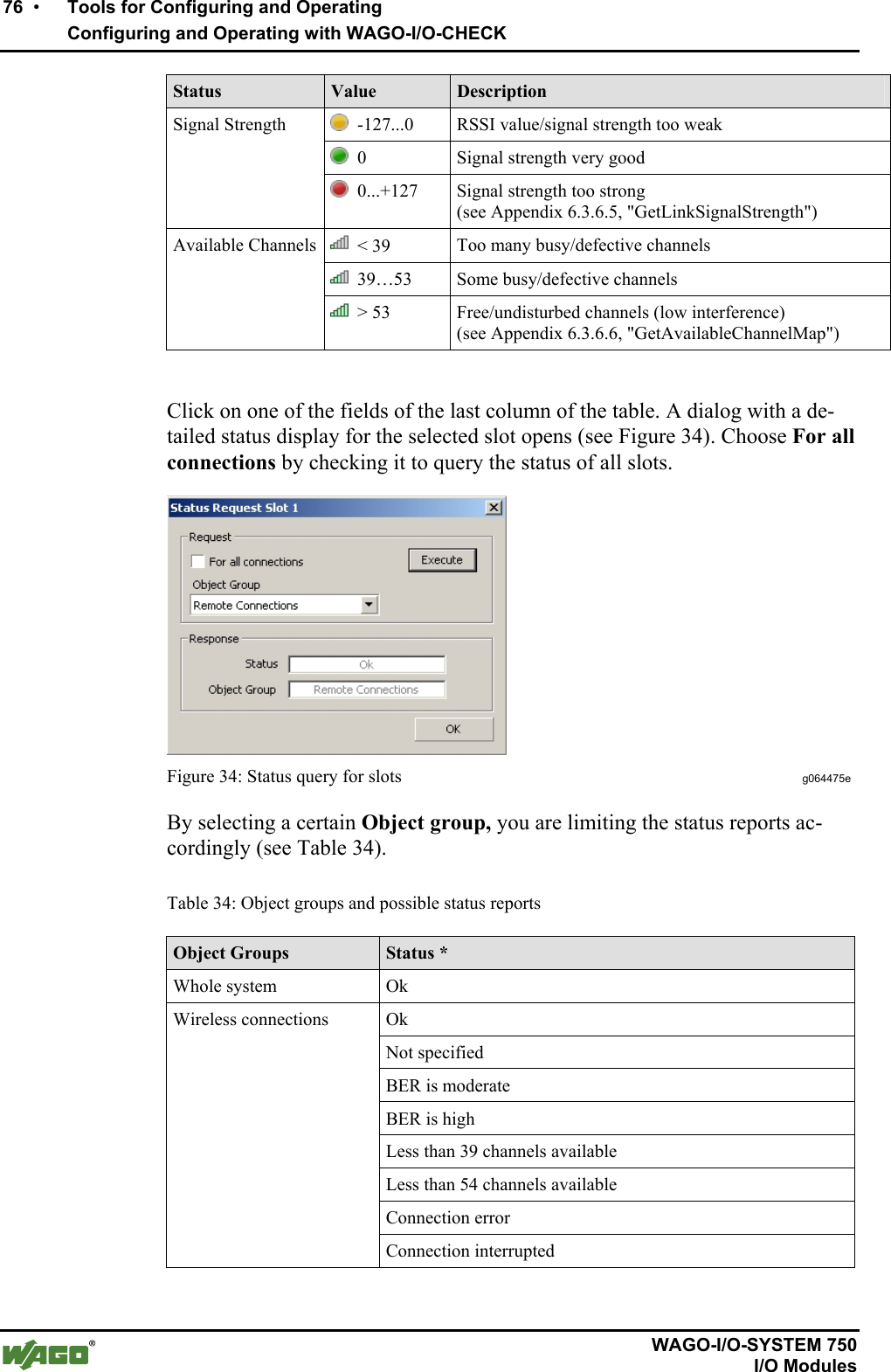
![Tools for Configuring and Operating • 81 Configuring the Bluetooth® Module 750-644 WAGO-I/O-SYSTEM 750 I/O Modules 4.2.6 Assigning Slave Process Data to Slots in the Master Choose Settings in the context menu of the selected module (node view or navigation) to open the parameterization dialog. Click on PI Mapping in the navigation area. The master only considers parts of the individual slave process images. Select the size of these parts (cutoff) using the slide control. As an alternative, you can enter the number of bytes in the entry field to the side. Please note: Only up to 7 real-time devices or up to 6 ad hoc devices can be active at the same time. These are the only devices you can bind by selecting Bind - "Yes" in the PI Mapping configuration area for communication. If you bind all 13 devices and each of the 13 slots is occupied, only the first six real-time devices and the first ad hoc device will be free for communication. 4.2.7 Diagnostics Choose Settings in the context menu of the selected module (node view or navigation) to open the parameterization dialog. Click on Diagnostics in the navigation area. On this page, you will see status reports for the Bluetooth® device, the trans-mission channel and network displayed. Click on the [Start Diagnostics] but-ton to constantly query current values. Click on [Stop Diagnostics] to display the most recently received status with no further updating. A click on the right column of the table opens a dialog window in which you can query status information for individual slots or all existing connections by selecting an object group and clicking [Execute]. Additional Information An example configuration using WAGO-I/O-CHECK can be found in Ap-pendix 6.5.](https://usermanual.wiki/u-blox/WTB08/User-Guide-1066128-Page-81.png)

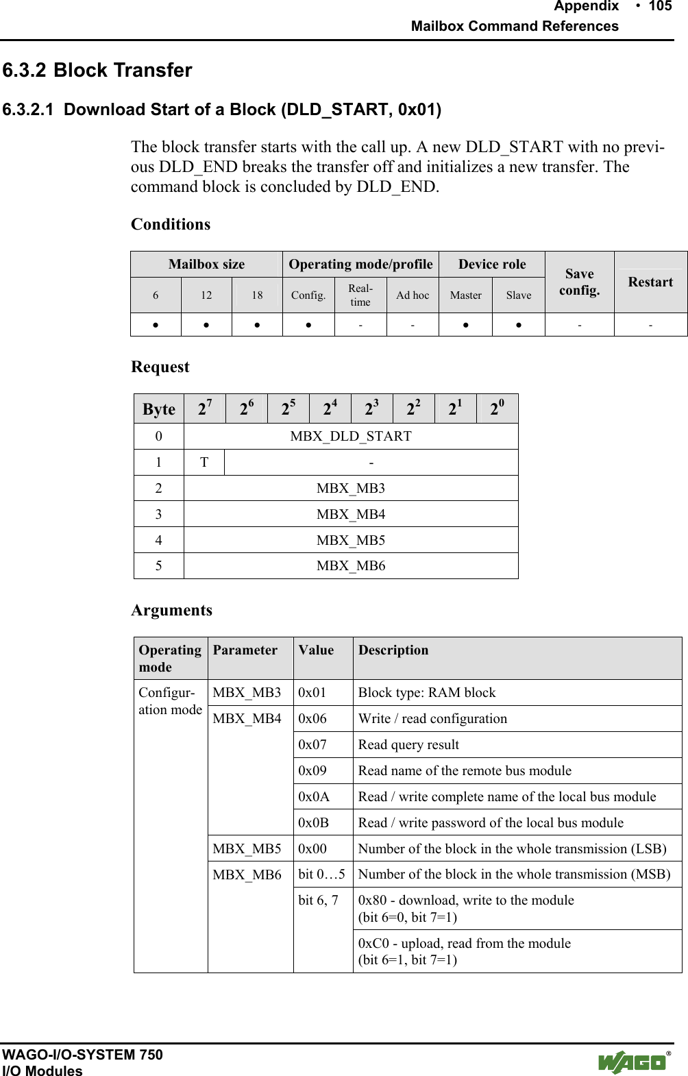
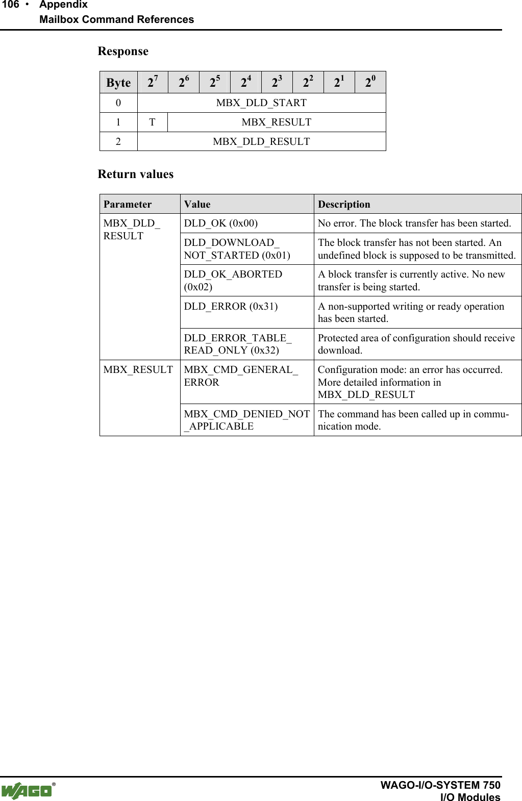
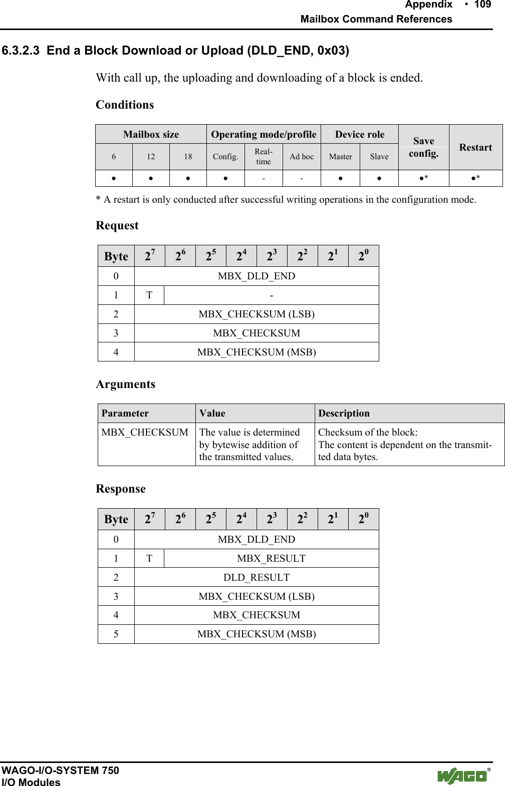
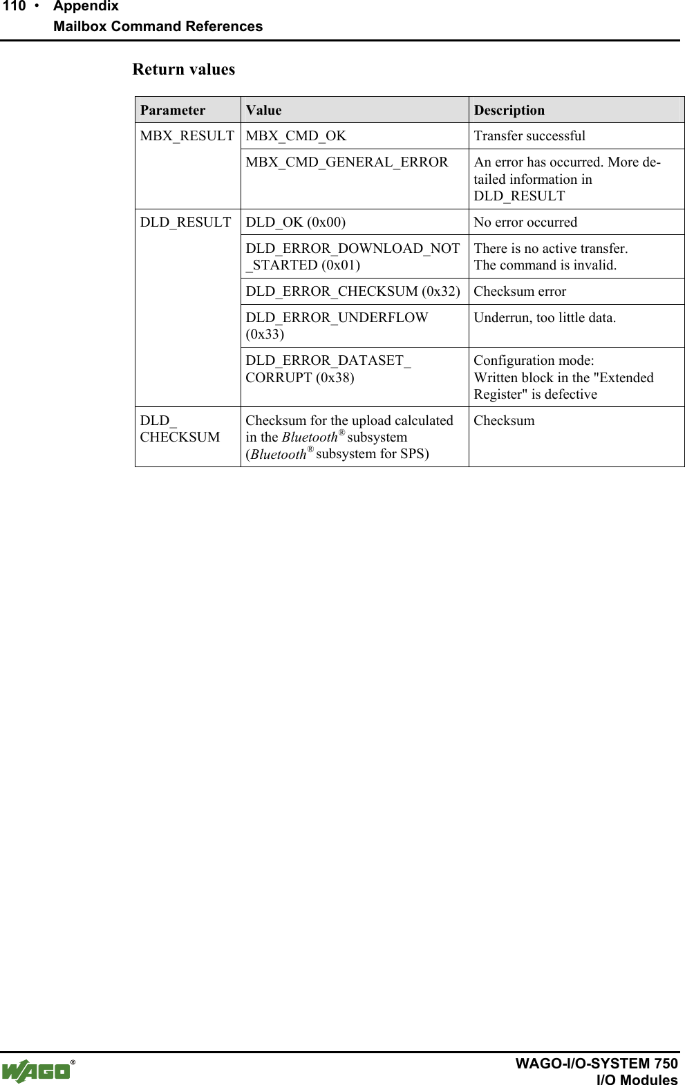
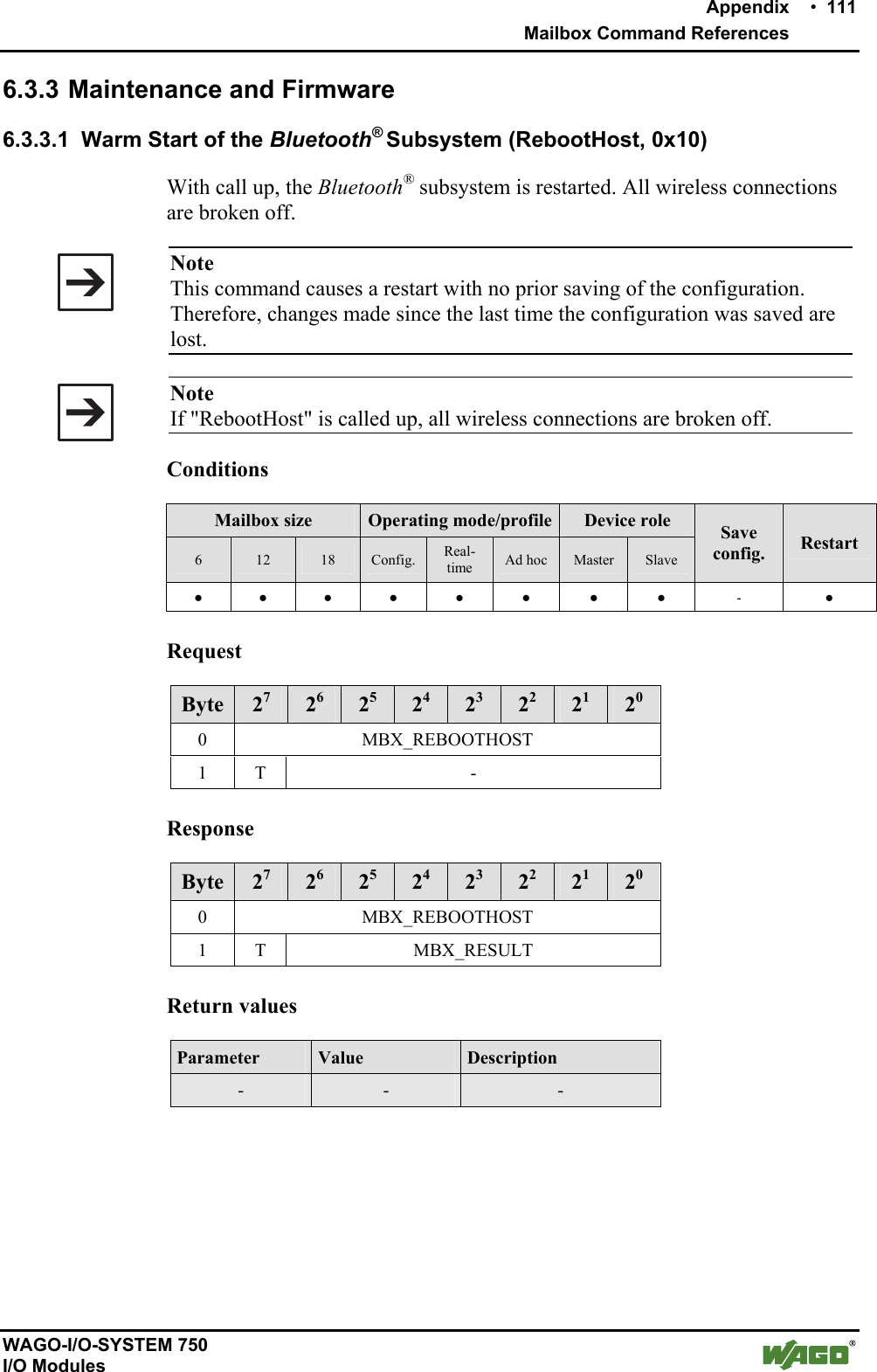
![Appendix • 107 Mailbox Command References WAGO-I/O-SYSTEM 750 I/O Modules 6.3.2.2 Continuation of a Block Download or Upload (DLD_CONT, 0x02) With call up, the uploading/downloading of a block is continued. During an upload of data to the module, the data bytes from byte 2 may be ignored. Conditions Mailbox size Operating mode/profile Device role 6 12 18 Config. Real-time Ad hoc Master Slave Save config. Restart ● ● ● ● - - ● ● - - Request Byte 27 26 25 24 23 22 21 20 0 MBX_DLD_CONT 1 T - 2 DATA 3 DATA 4 DATA 5 DATA 6 OPTIONAL DATA ... ... 17 OPTIONAL DATA Arguments Parameter Value Description DATA OPTIONAL DATA[0x00...0xFF] Transmitted data bytes In configuration mode, the number of data bytes is based on the mailbox size - 2. During a download from the module, the values of the data bytes are ignored.](https://usermanual.wiki/u-blox/WTB08/User-Guide-1066128-Page-107.png)
![108 • Appendix Mailbox Command References WAGO-I/O-SYSTEM 750 I/O Modules Response Byte 27 26 25 24 23 22 21 20 0 MBX_DLD_CONT 1 T MBX_RESULT 2 DATA 3 DATA 4 DATA 5 DATA 6 OPTIONAL DATA ... ... 33 OPTIONAL DATA Return values Parameter Value Description MBX_CMD_OK No error occurred. The block transfer has been continued. MBX_CMD_DENIED_NOT_ APPLICABLE There is no active transfer. The command is invalid. MBX_RESULT MBX_CMD_OUT_OF_RANGE An attempt was made to transfer more than 512 bytes. DATA OPTIONAL DATA [0x00...0xFF] Transmitted data bytes In configuration mode, the number of data bytes is based on the mailbox size - 2. During data upload to the module, data bytes are initialized in the response with 0x00 and can be ignored.](https://usermanual.wiki/u-blox/WTB08/User-Guide-1066128-Page-108.png)
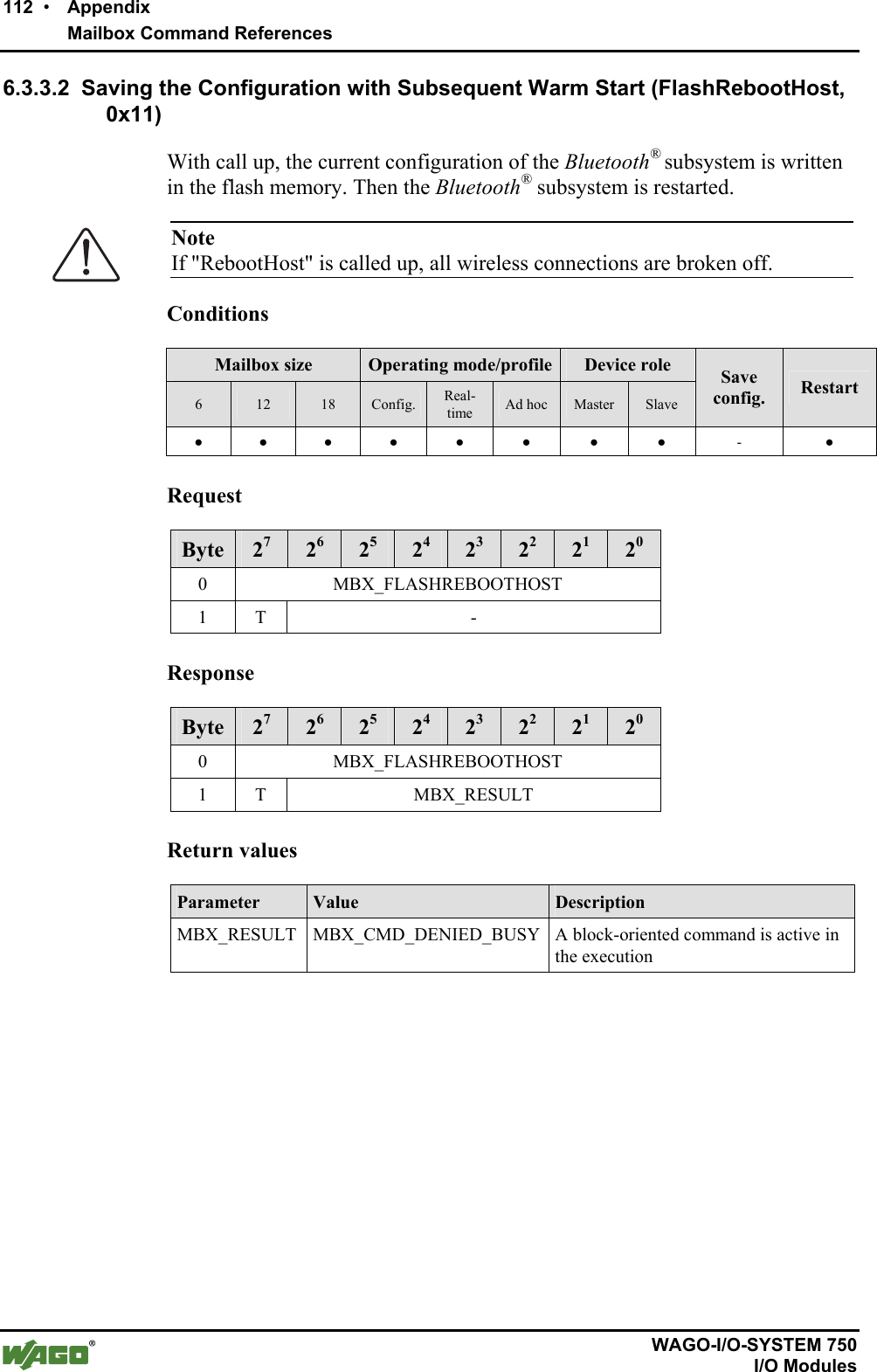
![114 • Appendix Mailbox Command References WAGO-I/O-SYSTEM 750 I/O Modules Return values Parameter Value Description MBX_RESULT MBX_CMD_INVALID_ARG Invalid value for MBX_FW_ID MBX_CM_GETHOSTFWVERSION_BOOTLOADER (0x01) Version of boot loader MBX_CM_GETHOSTFWVERSION_FIRMWARE (0x02) Version of Bluetooth® subsystem MBX_FW_ID MBX_CM_GETHOSTFWVERSION_CONFIGURATION (0x03) Version of configura-tion MBX_VN_MAJOR [0...255] Main version number MBX_VN_MINOR [0...255] Subversion number MBX_VN_RELEASE [0...255] Release of subversion](https://usermanual.wiki/u-blox/WTB08/User-Guide-1066128-Page-114.png)
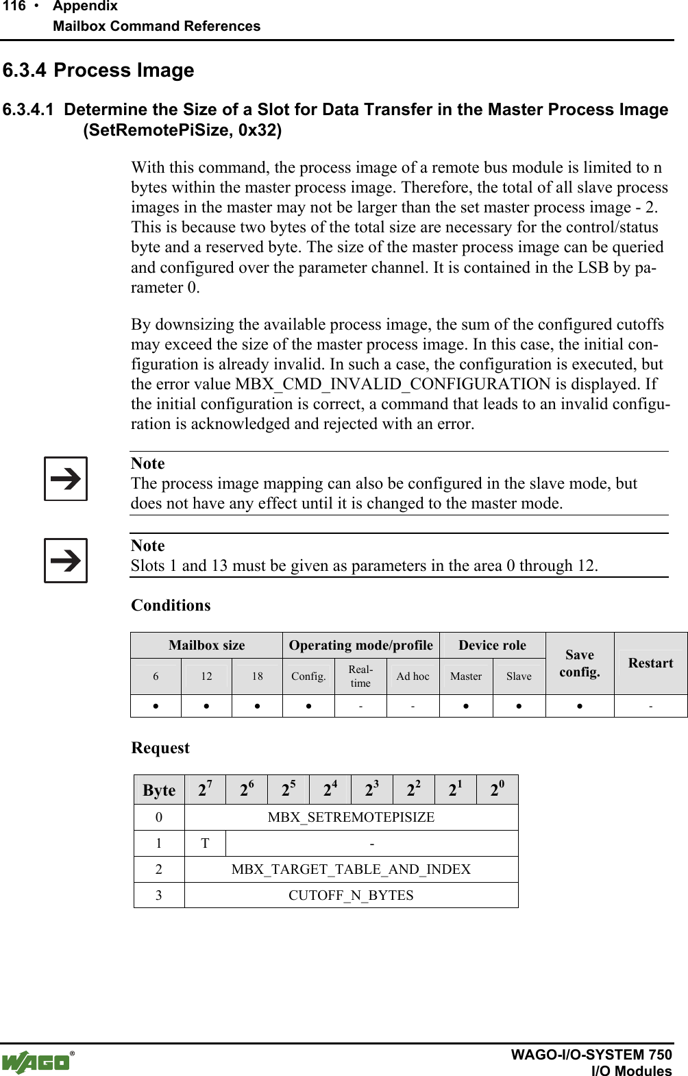
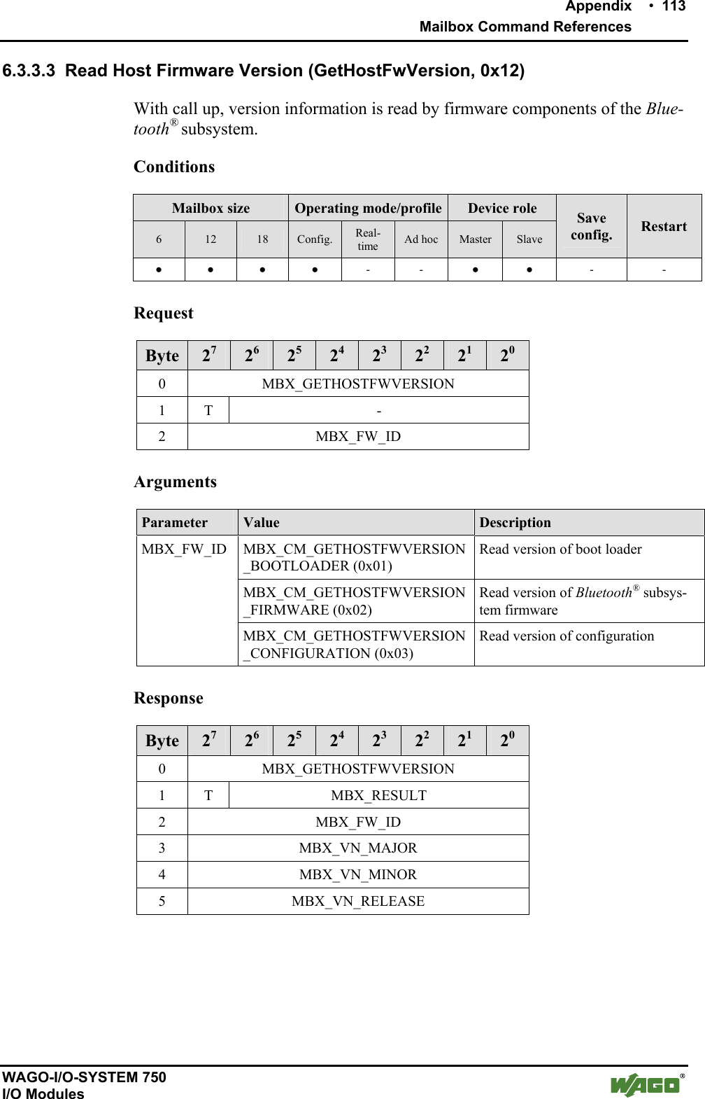
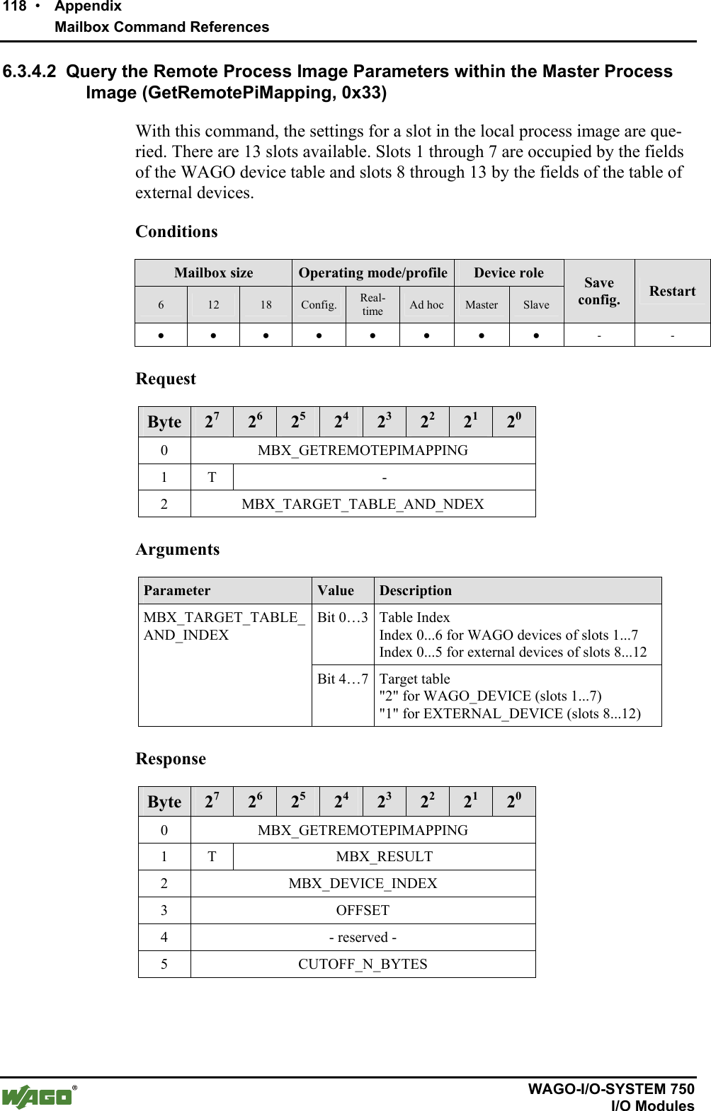
![Appendix • 117 Mailbox Command References WAGO-I/O-SYSTEM 750 I/O Modules Arguments Parameter Value Description Bit 0…3 Table Index Index 0...6 for WAGO devices of slots 1...7 Index 0...5 for external devices of slots 8...12 MBX_TARGET_TABLE_AND_INDEX Bit 4…7 Target table "2" for WAGO_DEVICE (slots 1...7) "1" for EXTERNAL_DEVICE (slots 8...12) CUTOFF_N_BYTES [0...46] Number of bytes after which the slave process image is cut off. The redundant bytes will be lost. Response Byte 27 26 25 24 23 22 21 20 0 MBX_SETREMOTEPISIZE 1 T MBX_RESULT Return values Parameter Value Description MBX_CMD_INVALID_ CONFIGURATION Before and after the command, the sum of all CUTOFF_N_BYTES is larger than the available master process image.MBX_CMD_INVALID_ARG No valid target table has been chosen. MBX_ RESULT MBX_CMD_OUT_OF_RANGE With the given value, the sum of all CUTOFF_N_BYTES would exceed the limit of the available master process image or the indicated index is too large.](https://usermanual.wiki/u-blox/WTB08/User-Guide-1066128-Page-117.png)
![Appendix • 119 Mailbox Command References WAGO-I/O-SYSTEM 750 I/O Modules Return values Parameter Value Description MBX_CMD_INVALID_ARG No valid target table has been chosen. MBX_RESULT MBX_CMD_OUT_OF _RANGE The indicated index is too large. MBX_DEVICE_INDEX [0...12] Slot of the slave process image within the master process image OFFSET [0...45] Position of the first byte of the slot in the local process image relative to the C/S byte. Slot 1 always has an offset of 0. CUTOFF_N_BYTES Number Number of bytes after which the slave process image is cut off. - reserved - 0x00 Reserved for later use.](https://usermanual.wiki/u-blox/WTB08/User-Guide-1066128-Page-119.png)
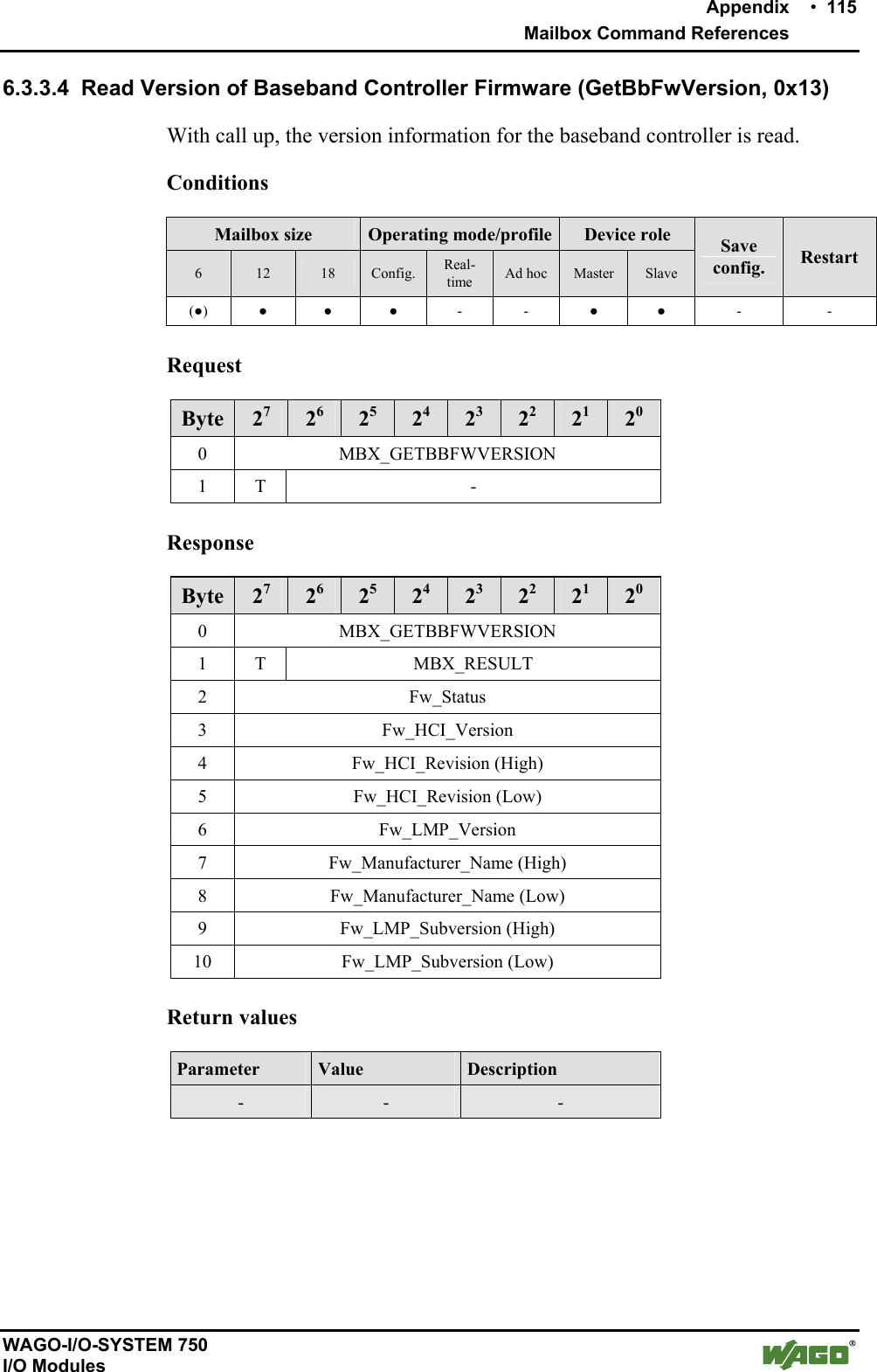
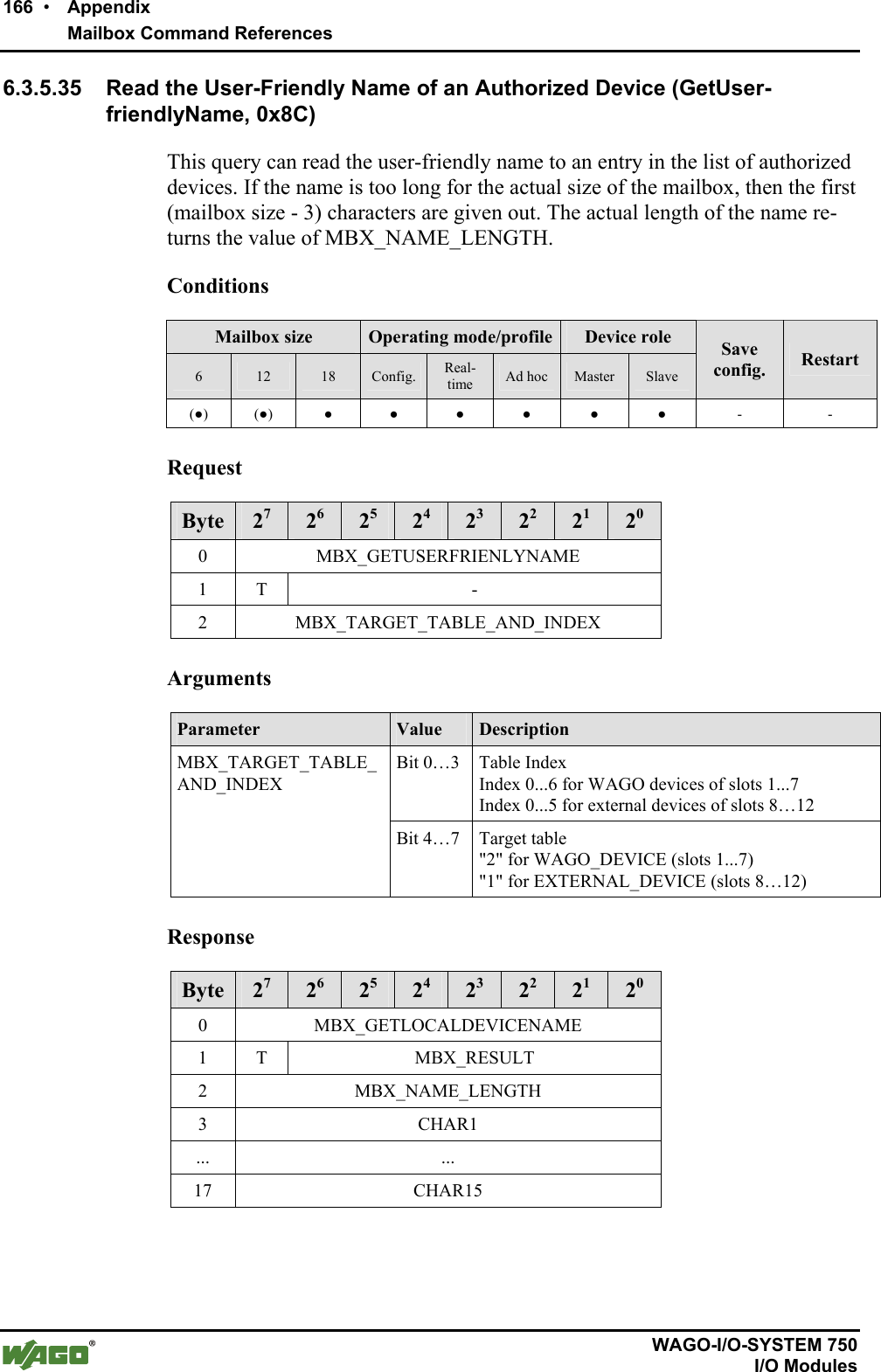
![120 • Appendix Mailbox Command References WAGO-I/O-SYSTEM 750 I/O Modules 6.3.5 Device Configuration 6.3.5.1 Read the Local Device Name(GetLocalDeviceName, 0x40) The characters of the Bluetooth® name of the local bus module are read by this query. The number of characters returned depends on the configured name, but has a maximum of (mailbox size - 3). Note The complete device name can be a maximum of 15 characters. The complete device name can be queried with DLD commands regardless of the mailbox size.Conditions Mailbox size Operating mode/profile Device role 6 12 18 Config. Real-time Ad hoc Master Slave Save config. Restart (●) (●) ● ● - - ● ● - - Request Byte 27 26 25 24 23 22 21 20 0 MBX_GETLOCALDEVICENAME 1 T - Response Byte 27 26 25 24 23 22 21 20 0 MBX_GETLOCALDEVICENAME 1 T MBX_RESULT 2 MBX_NAME_LENGTH 3 CHAR1 ... ... 17 CHAR15 Return values Parameter Value Description MBX_NAME_LENGTH [0...255] Number of characters of the complete name CHARn [0...255] Characters of the device name in ASCII code Example: "ABC" A = CHAR1 = 0x41 B = CHAR2 = 0x42 C = CHAR3 = 0x43](https://usermanual.wiki/u-blox/WTB08/User-Guide-1066128-Page-120.png)
![Appendix • 121 Mailbox Command References WAGO-I/O-SYSTEM 750 I/O Modules 6.3.5.2 Write the Local Device Name (SetLocalDeviceName, 0x41) With this command, the Bluetooth® name of the local bus module is set. The normal set of ASCII characters is available. Note The use of special characters (e.g. word wraps) is possible but should be avoided. The complete device name can be a maximum of 15 characters. The complete device name can be read and written with DLD commands regardless of the mailbox size. Conditions Mailbox size Operating mode/profile Device role 6 12 18 Config. Real-time Ad hoc Master Slave Save config. Restart (●) (●) ● ● - - ● ● - - Request Byte 27 26 25 24 23 22 21 20 0 MBX_SETLOCALDEVICENAME 1 T - 2 MBX_NAME_LENGTH 3 CHAR1 ... ... 17 CHAR15 Arguments Parameter Value Description MBX_NAME_LENGTH [1...15] Number of the transferred characters of the name CHARn Characters of the device name in ASCII code Example: "ABC" A = CHAR1 = 0x41 B = CHAR2 = 0x42 C = CHAR3 = 0x43 Response Byte 27 26 25 24 23 22 21 20 0 MBX_SETLOCALDEVICENAME 1 T MBX_RESULT](https://usermanual.wiki/u-blox/WTB08/User-Guide-1066128-Page-121.png)
![Appendix • 123 Mailbox Command References WAGO-I/O-SYSTEM 750 I/O Modules 6.3.5.3 Read Local MAC ID (GetLocalMacID, 0x42) With this command, the Bluetooth® MAC-ID (48-bit address) of the local Bluetooth® module is read. Conditions Mailbox size Operating mode/profile Device role 6 12 18 Config. Real-time Ad hoc Master Slave Save config. Restart - ● ● ● - - ● ● - - Request Byte 27 26 25 24 23 22 21 20 0 MBX_GETLOCALMACID 1 T - Response Byte 27 26 25 24 23 22 21 20 0 MBX_GETLOCALMACID 1 T MBX_RESULT 2 MAC-ID byte 0 (LSB) 3 MAC-ID byte 1 4 MAC-ID byte 2 5 MAC-ID byte 3 6 MAC-ID byte 4 7 MAC-ID byte 5 (MSB) Return values Parameter Value Description MAC ID byte n [0…255] The bytes of the MAC address](https://usermanual.wiki/u-blox/WTB08/User-Guide-1066128-Page-123.png)
![124 • Appendix Mailbox Command References WAGO-I/O-SYSTEM 750 I/O Modules 6.3.5.4 Read Local IP Address (GetLocalIPAddress, 0x43) With this command, the IP address (IPv4) of the local bus module is read. Conditions Mailbox size Operating mode/profile Device role 6 12 18 Config. Real-time Ad hoc Master Slave Save config. Restart ● ● ● ● - - ● ● - - Request Byte 27 26 25 24 23 22 21 20 0 MBX_GETLOCALIPADDRESS 1 T - Response Byte 27 26 25 24 23 22 21 20 0 MBX_GETLOCALIPADDRESS 1 T MBX_RESULT 2 Ip-Addr_1 (LSB) 3 Ip-Addr_2 4 Ip-Addr_3 5 Ip-Addr_4 (LSB) Return values Parameter Value Description IP-Addr_1 … IP-Addr_4 [0...255] The bytes of the IPv4 address in the form IP-Addr_4.IP-Addr_3.IP-Addr_2.IPAddr_1](https://usermanual.wiki/u-blox/WTB08/User-Guide-1066128-Page-124.png)
![Appendix • 125 Mailbox Command References WAGO-I/O-SYSTEM 750 I/O Modules 6.3.5.5 Set Local IP Address (SetLocalIPAddress, 0x44) With this command, the IP address (IPv4) of the local bus module is read. Conditions Mailbox size Operating mode/profile Device role 6 12 18 Config. Real-time Ad hoc Master Slave Save config. Restart ● ● ● ● - - ● ● ● - Request Byte 27 26 25 24 23 22 21 20 0 MBX_SETLOCALIPADDRESS 1 T - 2 Ip-Addr_1 (LSB) 3 Ip-Addr_2 4 Ip-Addr_3 5 Ip-Addr_4 (MSB) Arguments Parameter Value Description IP-Addr_1 ... IP_Addr_4 [0...255] The bytes of the IPv4 address Response Byte 27 26 25 24 23 22 21 20 0 MBX_SETLOCALIPADDRESS 1 T MBX_RESULT Return values Parameter Value Description - - -](https://usermanual.wiki/u-blox/WTB08/User-Guide-1066128-Page-125.png)
![126 • Appendix Mailbox Command References WAGO-I/O-SYSTEM 750 I/O Modules 6.3.5.6 Read Local Subnet Mask (GetLocalSubnetMask, 0x45) With this command, the subnet mask (IPv4) of the local bus module is read. Conditions Mailbox size Operating mode/profile Device role 6 12 18 Config. Real-time Ad hoc Master Slave Save config. Restart ● ● ● ● - - ● ● - - Request Byte 27 26 25 24 23 22 21 20 0 MBX_GETLOCALSUBNETMASK 1 T - Response Byte 27 26 25 24 23 22 21 20 0 MBX_GETLOCALIPSUBCLASS 1 T MBX_RESULT 2 Subnet Mask -Addr_1 (LSB) 3 Subnet Mask -Addr_2 4 Subnet Mask -Addr_3 5 Subnet Mask -Addr_4 (MSB) Return values Parameter Value Description Subnet-Mask –Addr n [0...255] The bytes of the subnet mask](https://usermanual.wiki/u-blox/WTB08/User-Guide-1066128-Page-126.png)
![Appendix • 127 Mailbox Command References WAGO-I/O-SYSTEM 750 I/O Modules 6.3.5.7 Set Local Subnet Mask (SetLocalSubnetMask, 0x46) With this command, the subnet mask (IPv4) of the local bus module is written. Conditions Mailbox size Operating mode/profile Device role 6 12 18 Config. Real-time Ad hoc Master Slave Save config. Restart ● ● ● ● - - ● ● ● - Request Byte 27 26 25 24 23 22 21 20 0 MBX_SETLOCALSUBNETMASK 1 T - 2 Subnet-Mask -Addr_1 (LSB) 3 Subnet-Mask -Addr_2 4 Subnet-Mask -Addr_3 5 Subnet-Mask -Addr_4 (MSB) Arguments Parameter Value Description Subnet Mask-Addr_n [0...255] The bytes of the IPv4 subnet mask Response Byte 27 26 25 24 23 22 21 20 0 MBX_SETLOCALIPADDRESS 1 T MBX_RESULT Return values Parameter Value Description MBX_RESULT MBX_CMD_OK No error occurred](https://usermanual.wiki/u-blox/WTB08/User-Guide-1066128-Page-127.png)
![128 • Appendix Mailbox Command References WAGO-I/O-SYSTEM 750 I/O Modules 6.3.5.8 Read Local WAGO Device Class (GetLocalDeviceClass, 0x47) With this command, the WAGO device class of the local bus module is read. Types of modules can be differentiated using the device class. A grouping of modules according to their tasks is also possible. When searching for modules with a certain device class, an inquiry using the Bluetooth® Class-of-Device can help. The WAGO device classes have only an indirect relation to the Blue-tooth® Class-of-Device. The connection between the WAGO device classes and the Bluetooth® Class-of-Device is explained in Section 2.1.1.6.1. Conditions Mailbox size Operating mode/profile Device role 6 12 18 Config. Real-time Ad hoc Master Slave Save config. Restart ● ● ● ● - - ● ● - - Request Byte 27 26 25 24 23 22 21 20 0 MBX_GETLOCALDEVICECLASS 1 T - Response Byte 27 26 25 24 23 22 21 20 0 MBX_GETLOCALDEVICECLASS 1 T MBX_RESULT 2 WAGO_Deviceclass 3 WAGO_SubDeviceclass Return values Parameter Value Description WAGO_Deviceclass [0...7] Device class according to Section 2.1.1.6.1 WAGO_SubDeviceclass [0...7] Subdevice class according to Section 2.1.1.6.1](https://usermanual.wiki/u-blox/WTB08/User-Guide-1066128-Page-128.png)
![Appendix • 129 Mailbox Command References WAGO-I/O-SYSTEM 750 I/O Modules 6.3.5.9 Write Local Device Class (SetLocalDeviceClass, 0x48) With this command, the WAGO device class of the local bus module is writ-ten. Types of modules can be differentiated using the device class. A grouping of modules according to their tasks is also possible. When searching for mod-ules with a certain device class, an inquiry using the Bluetooth® Class-of-Device can help. The device classes have only an indirect relation to the Blue-tooth® Class-of-Device. The connection between the WAGO device classes and the Bluetooth® Class-of-Device is explained in Section 2.1.1.6.1. Conditions Mailbox size Operating mode/profile Device role 6 12 18 Config. Real-time Ad hoc Master Slave Save config. Restart ● ● ● ● - - ● ● ● - Request Byte 27 26 25 24 23 22 21 20 0 MBX_SETLOCALDEVICECLASS 1 T - 2 WAGO_Deviceclass 3 WAGO_SubDeviceclass Arguments Parameter Value Description WAGO_Deviceclass [0...7] Device class according to Section 2.1.1.6.1 WAGO_SubDeviceclass [0...7] Subdevice class according to Section 2.1.1.6.1 Response Byte 27 26 25 24 23 22 21 20 0 MBX_SETLOCALDEVICECLASS 1 T MBX_RESULT Return values Parameter Value Description MBX_RESULT MBX_CMD_INVALID_ARG Invalid value for WAGO_deviceclass or WAGO_SubDeviceclass](https://usermanual.wiki/u-blox/WTB08/User-Guide-1066128-Page-129.png)
![138 • Appendix Mailbox Command References WAGO-I/O-SYSTEM 750 I/O Modules 6.3.5.16 Read Local Bluetooth® Password (GetLocalPassphrase, 0x51) With call up, the encryption mode for the wireless transmission is read out. The password is transmitted as a byte value representation of ASCII charac-ters and is at least 4 characters long. Conditions Mailbox size Operating mode/profile Device role 6 12 18 Config. Real-time Ad hoc Master Slave Save config. Restart - (●) (●) ● - - ● ● - - Request Byte 27 26 25 24 23 22 21 20 0 MBX_GETLOCALPASSPHRASE 1 T - Response Byte 27 26 25 24 23 22 21 20 0 MBX_GETLOCALPASSPHRASE 1 T MBX_RESULT 2 MBX_PASSPHRASE_Length 3 MBX_PASSPHRASE_Byte 1 4 MBX_PASSPHRASE_Byte 2 5 MBX_PASSPHRASE_Byte 3 6 MBX_PASSPHRASE_Byte 4 7 OPTIONAL PASSPHRASE_Byte 5 ... … 17 OPTIONAL PASSPHRASE_Byte 15 Note If the password is longer than the available mailbox, the excess bytes are cut off. MBX_ PASSPHRASE _Length reproduces the actual password length. Therefore, the real password may therefore deviate from the indicated length. Return values Parameter Value Description MBX_PASSPHRASE_Length [4…15] Complete length of the password MBX_ PASSPHRASE_Byte n Characters (ASCII) Password as ASCII representation](https://usermanual.wiki/u-blox/WTB08/User-Guide-1066128-Page-138.png)
![Appendix • 139 Mailbox Command References WAGO-I/O-SYSTEM 750 I/O Modules 6.3.5.17 Write Local Bluetooth® Password (SetLocalPassphrase, 0x52) With this command, the local password can be configured. The module calcu-lates the "Link Key" from the locally saved password. This is necessary during active authentication for the establishment and data encryption. The Blue-tooth® password must therefore be identical for all devices intended to com-municate with each other. Note Security quality depends on the selected password. The password should be as long as possible and selected randomly. Modules can only connect to each other if they have the same settings for encryption, authentication and password. Conditions Mailbox size Operating mode/profile Device role 6 12 18 Config. Real-time Ad hoc Master Slave Save config. Restart - (●) (●) ● - - ● ● ● - Request Byte 27 26 25 24 23 22 21 20 0 MBX_SETLOCALPASSPHRASE 1 T - 2 MBX_PSW_Length 3 MBX_PSW_Byte 1 4 MBX_PSW_Byte 2 5 MBX_PSW_Byte 3 6 MBX_PSW_Byte 4 7 OPTIONAL MBX_PASSPHRASE_Byte 5 ... … 17 OPTIONAL MBX_PASSPHRASE_Byte 15 Arguments Parameter Value Description MBX_PASSPHRASE_Length [4...15] Password length MBX_ PASSPHRASE_Byte n Characters (ASCII) Password as ASCII representation](https://usermanual.wiki/u-blox/WTB08/User-Guide-1066128-Page-139.png)
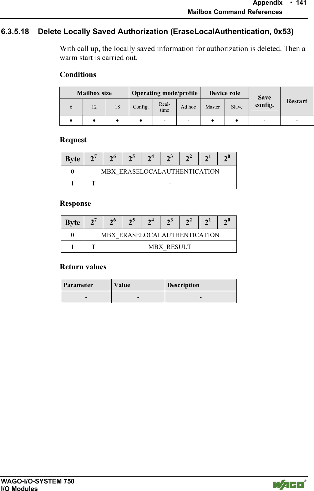
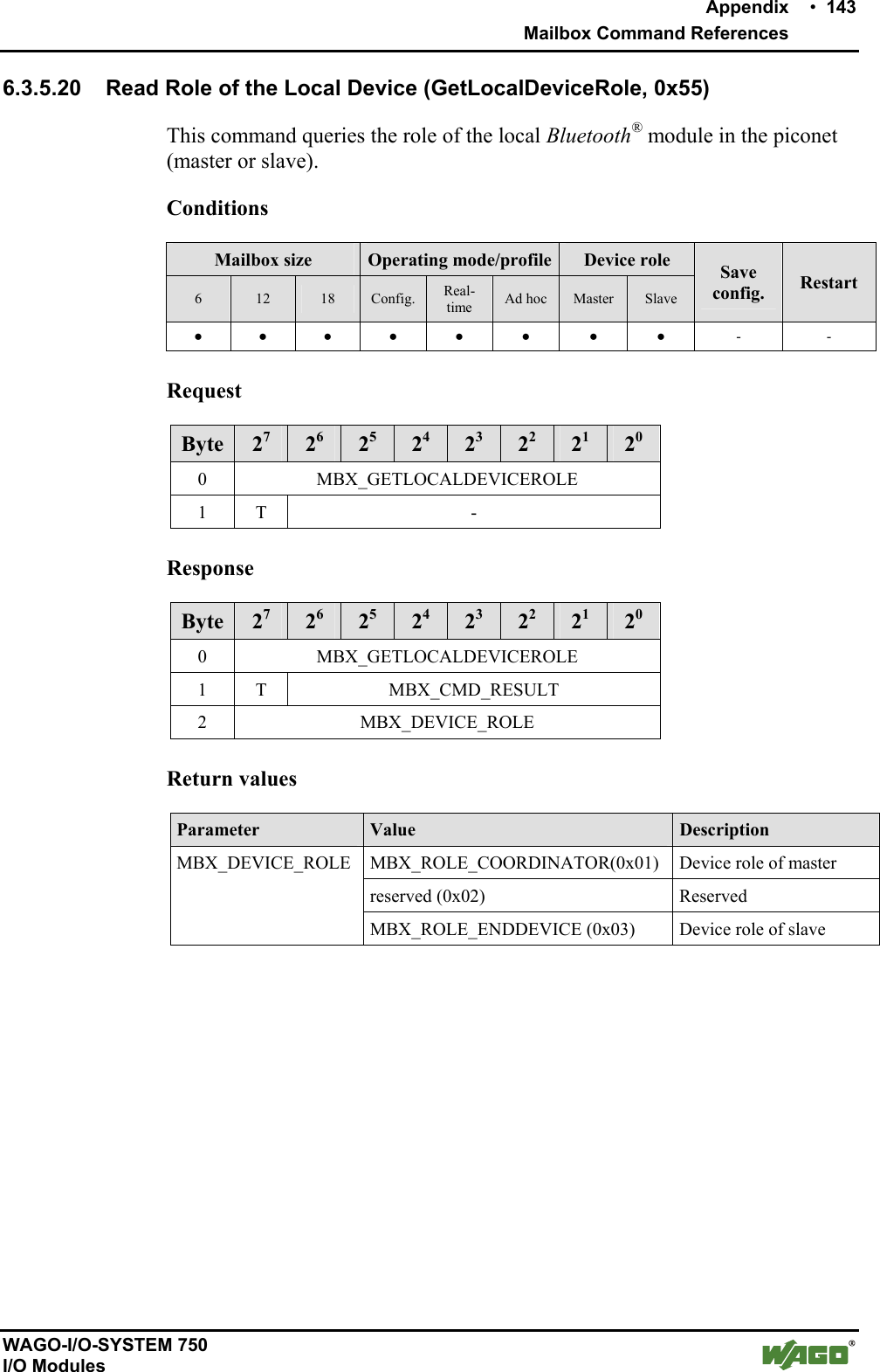
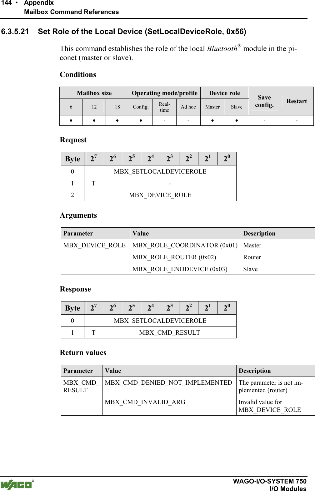
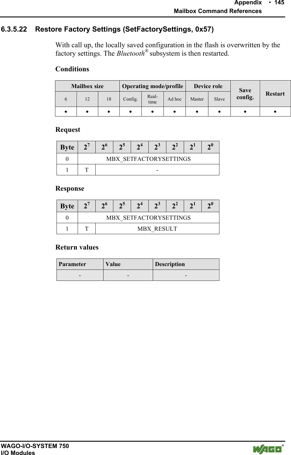
![142 • Appendix Mailbox Command References WAGO-I/O-SYSTEM 750 I/O Modules 6.3.5.19 Read Length of the Flash Configuration (GetLocalDeviceConfigLen, 0x54) With call up, the length (in bytes) of the locally saved configuration in the flash of the Bluetooth® subsystem is passed back. This information is used by the PLC for interpretation of data from the block commands. Conditions Mailbox size Operating mode/profile Device role 6 12 18 Config. Real-time Ad hoc Master Slave Save config. Restart ● ● ● ● - - ● ● - - Request Byte 27 26 25 24 23 22 21 20 0 MBX_GETLOCALDEVICECONFIGLEN 1 T - Response Byte 27 26 25 24 23 22 21 20 0 MBX_GETLOCALDEVICECONFIGLEN 1 T MBX_RESULT 2 MBX_CONFIG_LENGTH (LSB) 3 MBX_CONFIG_LENGTH (MSB) Return values Parameter Value Description MBX_CONFIG_LENGTH [0…65535] Length of the configuration (number of bytes) saved in the flash.](https://usermanual.wiki/u-blox/WTB08/User-Guide-1066128-Page-142.png)
![148 • Appendix Mailbox Command References WAGO-I/O-SYSTEM 750 I/O Modules 6.3.5.24 Read MAC-ID of a Remote Bluetooth® Device (GetRemoteDeviceMacID, 0x81) This command accesses a list of visible Bluetooth® devices in the environment and queries the Bluetooth® MAC-ID of a remote device. The prerequisite for this command is the prior execution of a search process with the command "ScanRemoteDevices", which initiates the creation of this list. If an attempt is made to access the list before the search process is complete, the command answers with MBX_CMD_DENIED_BUSY. In this case, the query should be repeated after a certain waiting period. Conditions Mailbox size Operating mode/profile Device role 6 12 18 Config. Real-time Ad hoc Master Slave Save config. Restart - ● ● ● - - ● ● - - Request Byte 27 26 25 24 23 22 21 20 0 MBX_GETREMOTEDEVICEMACID 1 T - 2 MBX_DEVICE_INDEX Arguments Parameter Value Description MBX_DEVICE_INDEX [0 ...15] Index of the device whose MAC-ID is to be read. A maximum of 16 found devices are administered. Response Byte 27 26 25 24 23 22 21 20 0 MBX_GETREMOTEDEVICEMACID 1 T MBX_RESULT MBX_NR_FOUND_DEVICES 2 MBX_MACID_BYTE (LSB) 3 MBX_MACID_BYTE 4 MBX_MACID_BYTE 5 MBX_MACID_BYTE 6 MBX_MACID_BYTE 7 MBX_MACID_BYTE (MSB)](https://usermanual.wiki/u-blox/WTB08/User-Guide-1066128-Page-148.png)
![Appendix • 149 Mailbox Command References WAGO-I/O-SYSTEM 750 I/O Modules Return values Parameter Value Description MBX_CMD_DENIED_BUSY The search process has not yet been stated or concluded. MBX_RESULT MBX_CMD_OUT_OF_RANGE The indicated index is greater than or equal to the number of the devices found. Or, no Bluetooth® device with the indicated Class-of-Device was found. MBX_MACID_BYTE Bytes of the MAC-ID Valid if MBX_RESULT = MBX_CMD_OK MBX_NR_FOUND_DEVICES [0...15] Number of devices found; if no devices were found, this parameter has the value 0 and MBX_RESULT has the value MBX_CMD_OUT_OF_RANGE](https://usermanual.wiki/u-blox/WTB08/User-Guide-1066128-Page-149.png)
![Appendix • 151 Mailbox Command References WAGO-I/O-SYSTEM 750 I/O Modules Arguments Parameter Value Description MBX_DEVICE_INDEX [0 ...15] List index for the return of the device name. The index must be smaller than the number of devices found in the search process. Response Byte 27 26 25 24 23 22 21 20 0 MBX_GETREMOTEDEVICENAME 1 T MBX_RESULT 2 MBX_NAME_LENGTH 3 CHAR1 ... ... 17 CHAR15 Return values Parameter Value Description MBX_CMD_OUT_OF_RANGE No valid device was found in the scan list for the delivered index. MBX_CMD_DENIED_BUSY The search process has not yet been stated or not yet concluded. MBX_ RESULT MBX_CMD_TIMEOUT The remote device has rejected the name query or has not responded within the time prescribed by the Bluetooth® standard. MBX_NAME _LENGTH [0...255] Number of characters in the complete name. CHARn ASCII characters Characters of the device name in ASCII code Example: ABC A = CHAR1 = 0x41 B = CHAR2 = 0x42 C = CHAR3 = 0x43](https://usermanual.wiki/u-blox/WTB08/User-Guide-1066128-Page-151.png)
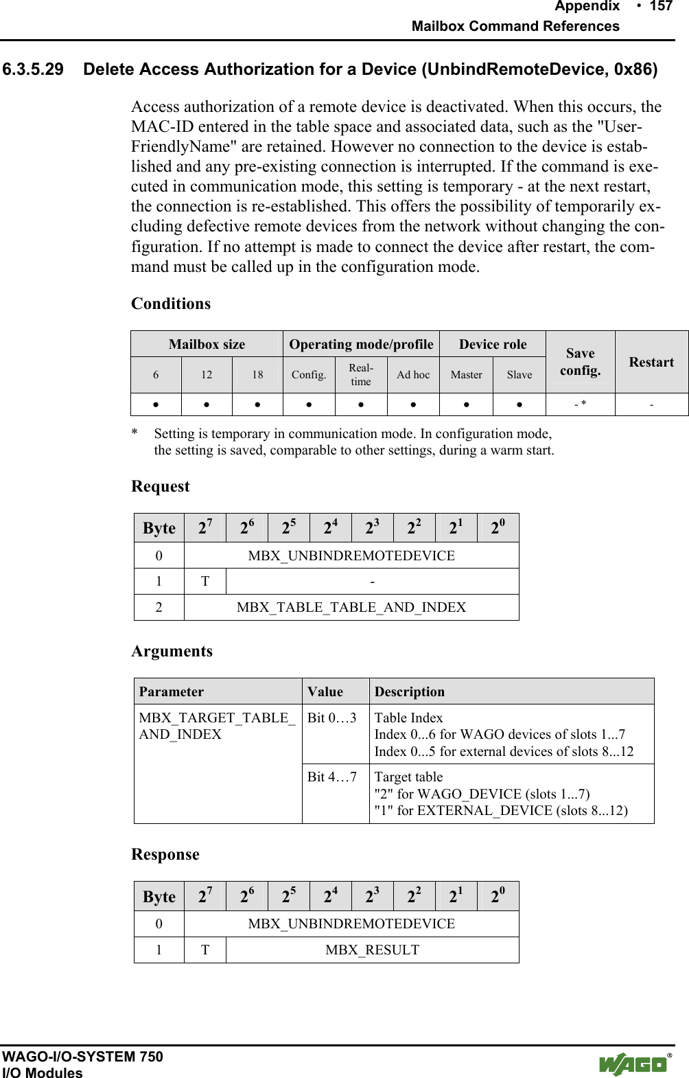
![152 • Appendix Mailbox Command References WAGO-I/O-SYSTEM 750 I/O Modules 6.3.5.26 Enter External Device in the Table of Authorized Devices (AllowRemoteDevice, 0x83) This command allows a remote device to access the local device. The MAC-ID of the remote device is also entered in a table of the Bluetooth® subsystem. Two device types are differentiated. Both types are entered in different tables: WAGO devices for real-time communication: WAGO_DEVICE (0x20...0x26) External devices for communication over SPP[1] or PAN[2]: EXTERNAL_DEVICE (0x10...0x15) [1] Bluetooth® Specification: device supports the Serial Port Profile (SPP) [2] Bluetooth® Specification: device supports the Personal Area Network (PAN) Profile Note Before an entered WAGO device is actually authorized for access, it must be activated using command "BindRemoteDevice". The access authorization can be withdrawn again via command "UnbindRe-moteDevice" without requiring deletion of the device from the table. Entries can be deleted from the table by overwriting with the MAC-ID 00:00:00:00:00:00. The affected slot is filled with zeros and no data is trans-mitted to it. Changes to the device blocks do not change anything in the proc-ess image mapping. A MAC-ID (except for 00:00:00:00:00:00) may never occur more than once in the table. Conditions Mailbox size Operating mode/profile Device role 6 12 18 Config. Real-time Ad hoc Master Slave Save config. Restart - ● ● ● - - ● ● ● -](https://usermanual.wiki/u-blox/WTB08/User-Guide-1066128-Page-152.png)
![Appendix • 153 Mailbox Command References WAGO-I/O-SYSTEM 750 I/O Modules Request Byte 27 26 25 24 23 22 21 20 0 MBX_ALLOWREMOTEDEVICE 1 T - 2 MBX_TARGET_TABLE_AND_ INDEX 3 MAC_ID_Byte 0 (LSB) 4 MAC_ID_Byte 1 5 MAC_ID_Byte 2 6 MAC_ID_Byte 3 7 MAC_ID_Byte 4 8 MAC_ID_Byte 5 (MSB) Arguments Parameter Value Description Bit 0…3 Table Index Index 0...6 for WAGO devices of slots 1...7 Index 0…5 for external devices of slots 8...12 MBX_TARGET_TABLE_AND_INDEX Bit 4…7 Target table "2" for WAGO_DEVICE (slots 1...7) "1" for EXTERNAL_DEVICE (slots 8…12) MAC ID Byte n [0...255] The bytes of the MAC-ID to be entered Response Byte 27 26 25 24 23 22 21 20 0 MBX_ALLOWREMOTEDEVICE 1 T MBX_RESULT Return values Parameter Value Description MBX_CMD_OUT_OF_RANGE A maximum of seven WAGO devices or six external devices can be config-ured. This number has been exceeded. MBX_RESULT MBX_CMD_INVALID_ARG The indicated MAC-ID is already in the table or a false table ID has been given.](https://usermanual.wiki/u-blox/WTB08/User-Guide-1066128-Page-153.png)
![154 • Appendix Mailbox Command References WAGO-I/O-SYSTEM 750 I/O Modules 6.3.5.27 Read Back External Device from the Table of Authorized Devices (GetAllowedRemoteDevices, 0x84) This command reads out and returns the MAC-ID of a remote device from the table of authorized devices of the Bluetooth® subsystem. There are two types of external devices entered in different tables: WAGO devices for real-time communication: WAGO_DEVICE (0x20...0x26) External devices for communication over SPP[1] or PAN[2]: EXTERNAL_DEVICE (0x10…0x15) [1] Bluetooth® Specification: device supports the Serial Port Profile (SPP) [2] Bluetooth® Specification: device supports the Personal Area Network (PAN) Profile Note Before an entered WAGO device is actually authorized for access, it must be activated using the command "BindRemoteDevice". The access authorization can be withdrawn again using the command "Un-bindRemoteDevice" without making it necessary to delete the device from the table. Conditions Mailbox size Operating mode/profile Device role 6 12 18 Config. Real-time Ad hoc Master Slave Save config. Restart - ● ● ● - - ● ● - - Request Byte 27 26 25 24 23 22 21 20 0 MBX_GETALLOWEDREMOTEDEVICE 1 T - 2 MBX_TARGET_TABLE_AND_INDEX Arguments Parameter Value Description Bit 0…3 Table Index Index 0...6 for WAGO devices of slots 1...7 Index 0...5 for external devices of slots 8...12 MBX_TARGET_TABLE_AND_INDEX Bit 4…7 Target table "2" for WAGO_DEVICE (slots 1...7) "1" for EXTERNAL_DEVICE (slots 8...12)](https://usermanual.wiki/u-blox/WTB08/User-Guide-1066128-Page-154.png)
![Appendix • 155 Mailbox Command References WAGO-I/O-SYSTEM 750 I/O Modules Response Byte 27 26 25 24 23 22 21 20 0 MBX_GETALLOWEDREMOTEDEVICE 1 T MBX_RESULT 2 MAC_ID_Byte 0 (LSB) 3 MAC_ID_Byte 1 4 MAC_ID_Byte 2 5 MAC_ID_Byte 3 6 MAC_ID_Byte 4 7 MAC_ID_Byte 5 (MSB) Return values Parameter Value Description MBX_CMD_OUT_OF_RANGE An index greater than 6 was used. MBX_RESULT MBX_CMD_INVALID_ARG No valid target table chosen. MAC ID Byte n [0...255] The bytes of the MAC-ID read back.](https://usermanual.wiki/u-blox/WTB08/User-Guide-1066128-Page-155.png)
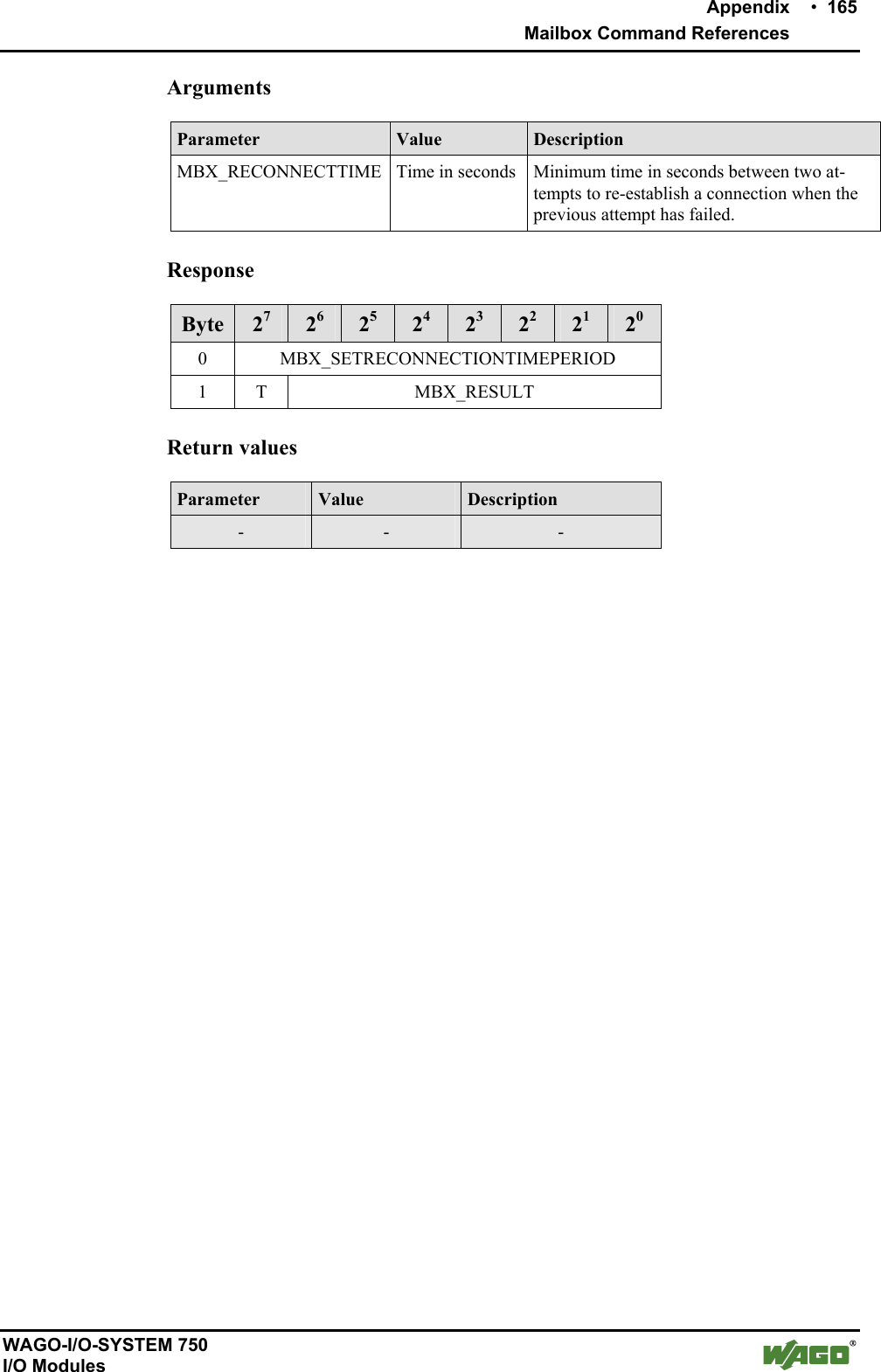
![Appendix • 163 Mailbox Command References WAGO-I/O-SYSTEM 750 I/O Modules 6.3.5.33 Read Back Time Settings - Between Two Attempts to Establish a Con-nection (GetReconnectionTimePeriod, 0x8A) This command reads back the waiting time between two attempts to re-establish the connection to a bus module. Conditions Mailbox size Operating mode/profile Device role 6 12 18 Config. Real-time Ad hoc Master Slave Save config. Restart ● ● ● ● - - ● ● - - Request Byte 27 26 25 24 23 22 21 20 0 MBX_GETRECONNECTIONTIMEPERIOD 1 T - Response Byte 27 26 25 24 23 22 21 20 0 MBX_GETRECONNECTIONTIMEPERIOD 1 T MBX_RESULT 2 MBX_RECONNECTTIME (LSB) 3 MBX_RECONNECTTIME (MSB) Return values Parameter Value Description MBX_RECONNECTTIME [0...65535] Minimum time interval (in seconds) between two attempts to re-establish a connection when the previous attempt has failed (value 0: no waiting between two attempts).](https://usermanual.wiki/u-blox/WTB08/User-Guide-1066128-Page-163.png)
![Appendix • 167 Mailbox Command References WAGO-I/O-SYSTEM 750 I/O Modules Return values Parameter Value Description MBX_CMD_OUT_OF_RANGE An index greater than 6 was used MBX_RESULT MBX_CMD_INVALID_ARG No valid target table has been chosen. MBX_NAME_LENGTH [0…15] Number of characters of the complete name CHARn [0...255] Characters of the device name in ASCII code Example: "ABC" A = CHAR1 = 0x41 B = CHAR2 = 0x42 C = CHAR3 = 0x43](https://usermanual.wiki/u-blox/WTB08/User-Guide-1066128-Page-167.png)
![Appendix • 169 Mailbox Command References WAGO-I/O-SYSTEM 750 I/O Modules Arguments Parameter Value Description Bit 0…3 Table Index Index 0...6 for WAGO devices of slots 1...7 Index 0...5 for external devices of slots 8...12 MBX_TARGET_TABLE_AND_INDEX Bit 4…7 Target table "2" for WAGO_DEVICE (slots 1...7) "1" for EXTERNAL_DEVICE (slots 8...12) MBX_NAME_LENGTH [0...15] Number of characters of the complete name CHARn [0...255] Characters of the device name in ASCII code 0x0 close the string Example: "ABC" A = CHAR1 = 0x41 B = CHAR2 = 0x42 C = CHAR3 = 0x43 End of the name = CHAR4 = 0x00 Response Byte 27 26 25 24 23 22 21 20 0 MBX_GETLOCALDEVICENAME 1 T MBX_RESULT Return values Parameter Value Description MBX_CMD_OUT_OF_RANGE An index > 6 (for WAGO devices) and > 5 (for external devices) were selected. MBX_RESULT MBX_CMD_INVALID_ARG No valid target table chosen.](https://usermanual.wiki/u-blox/WTB08/User-Guide-1066128-Page-169.png)
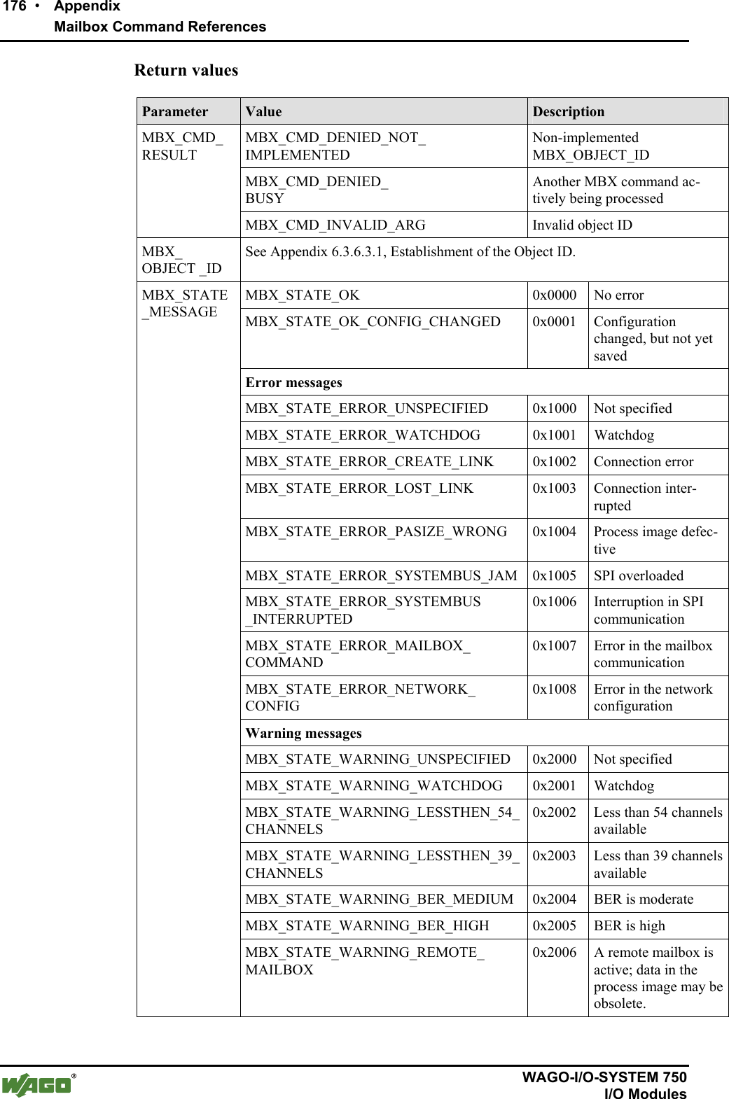
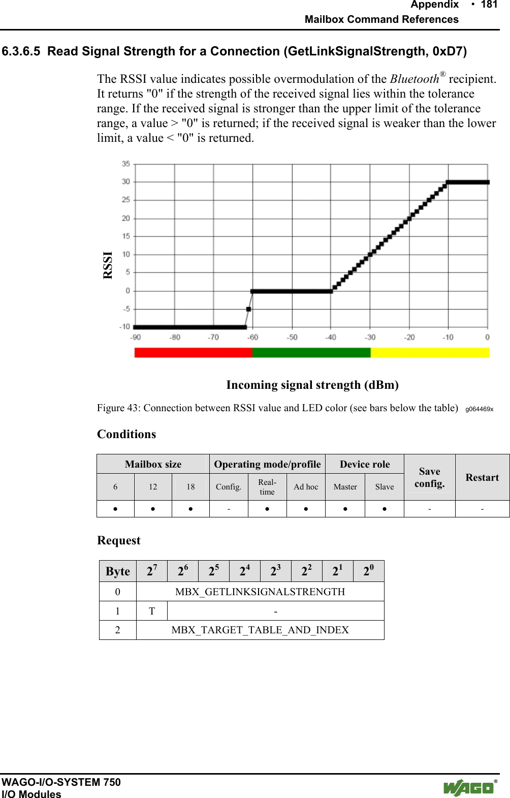
![180 • Appendix Mailbox Command References WAGO-I/O-SYSTEM 750 I/O Modules Arguments Parameter Value Description Bit 0…3 Table Index Index 0...6 for WAGO devices of slots 1...7 Index 0...5 for external devices of slots 8...12 MBX_TARGET_TABLE_AND_INDEX Bit 4…7 Target table "2" for WAGO_DEVICE (slots 1…7) "1" for EXTERNAL_DEVICE (slots 8…12) Response Byte 27 26 25 24 23 22 21 20 0 MBX_GETLINKQUALITY 1 T MBX_RESULT 2 MBX_LQ_VALUE Return values Parameter Value Description MBX_CMD_OUT_OF_RANGE Too large of an index was used. MBX_CMD_GENERAL_ERROR The device is not connected. MBX_RESULT MBX_CMD_INVALID_ARG The device is not connected or no valid target table was chosen. MBX_LQ_VALUE [0….255] Value of the connection quality for the requested connection](https://usermanual.wiki/u-blox/WTB08/User-Guide-1066128-Page-180.png)
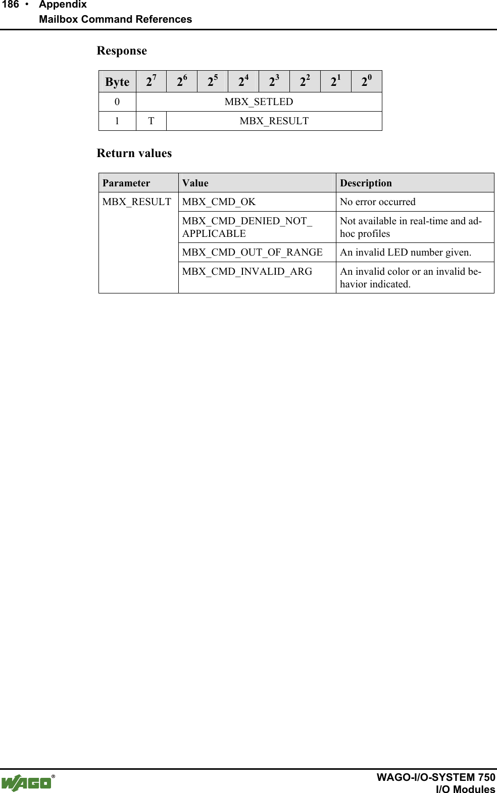
![Appendix • 185 Mailbox Command References WAGO-I/O-SYSTEM 750 I/O Modules 6.3.6.7 Set an LED (SetLED, 0xD9) Call up sets color and blink code of a defined LED. This can be used to test the functionality of the LED. Note To reinstate normal status information on the LEDs, the module must be re-started. This can be triggered by the corresponding mailbox command or by briefly switching off the power. Conditions Mailbox size Operating mode/profile Device role 6 12 18 Config. Real-time Ad hoc Master Slave Save config. Restart ● ● ● ● - - ● ● - - Request Byte 27 26 25 24 23 22 21 20 0 MBX_SETLED 1 T - 2 MBX_LED_NUMBER 3 MBX_LED_COLOR 4 MBX_LED_BLINK Arguments Parameter Value Description MBX_LED_NUMBER [0 ...7] Selection of the LED, top left LED0, to the right of that LED1, etc. MBX_LEDOFF (0x00) LED off MBX_LEDRED (0x01) LED color red MBX_LEDGREEN (0x02) LED color green MBX_LED_COLOR MBX_LEDYELLOW (0x03) LED color yellow MBX_LEDSTATIC (0x00) LED will remain lit MBX_LED_BLINK MBX_LEDBLINK (0x01) LED blinks](https://usermanual.wiki/u-blox/WTB08/User-Guide-1066128-Page-185.png)
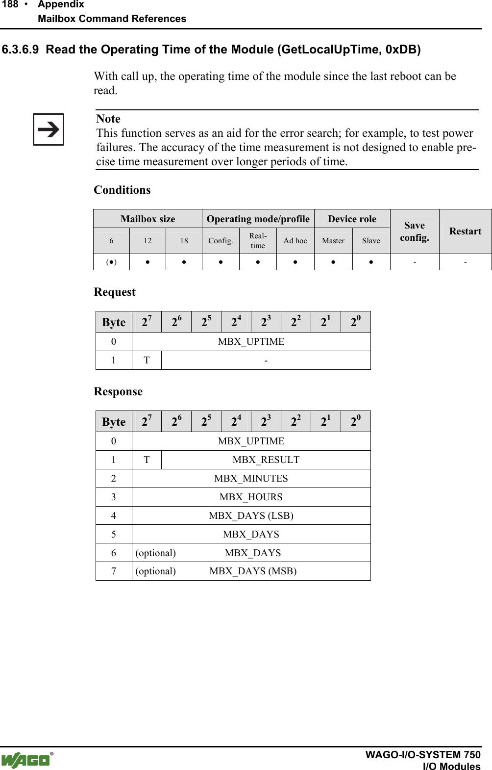
![Appendix • 189 Mailbox Command References WAGO-I/O-SYSTEM 750 I/O Modules Return values Parameter Value Description MBX_MINUTES [0...59] Minute portion of the operating time MBX_HOURS [0...24] Hour portion of the operating timeMBX_DAYS Mailbox size 6: [0…65.535] Mailbox size > 6: [0…4.294.967.295] Number of days the module has been operating; The two higher value bytes are only available with a mailbox > 6](https://usermanual.wiki/u-blox/WTB08/User-Guide-1066128-Page-189.png)
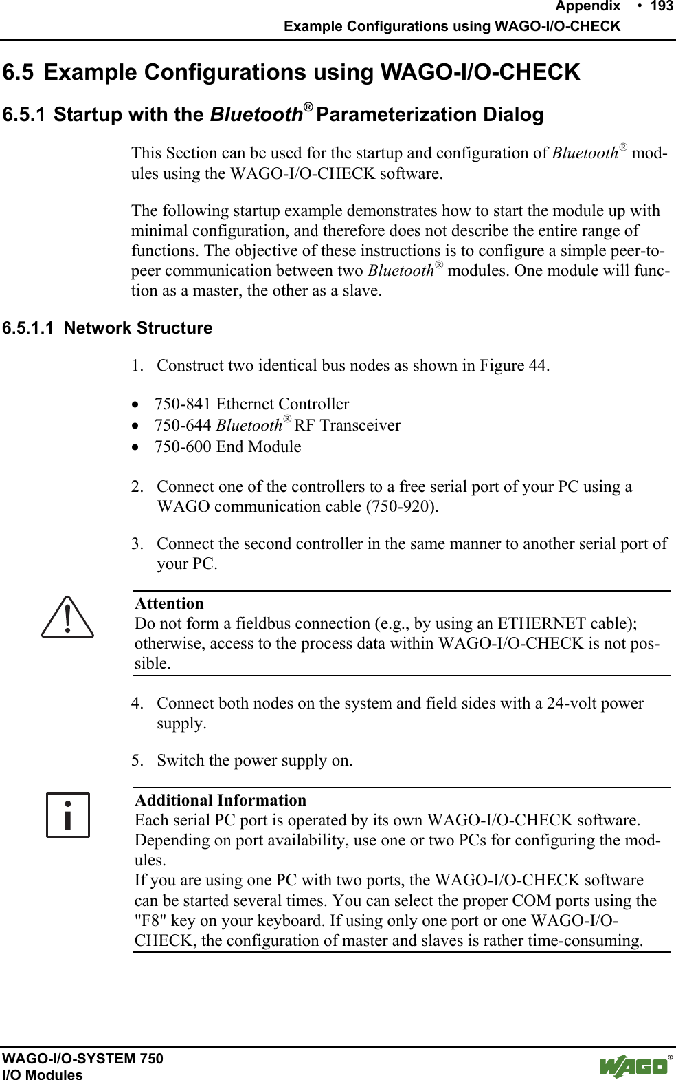
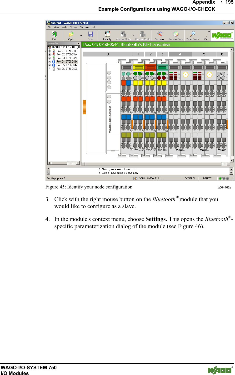
![194 • Appendix Example Configurations using WAGO-I/O-CHECK WAGO-I/O-SYSTEM 750 I/O Modules Figure 44: Hardware configuration g064461e 6.5.1.2 Starting up the Bluetooth® Modules 1. Determine which of your Bluetooth® modules will function as the master and which module will function as the slave. 2. Write down the MAC address of the slave: 0 0 : 0 6 : C 6 : _ _ : _ _ : _ _ Write down the MAC address of the master: 0 0 : 0 6 : C 6 : _ _ : _ _ : _ _ 6.5.1.2.1 Configuration of the Bluetooth® Slave using "Net Forming" 1. Start the WAGO-I/O-CHECK software (Version 3 or later). 2. Click on the [Identify] button. Your node configuration is graphically displayed (see Figure 45).](https://usermanual.wiki/u-blox/WTB08/User-Guide-1066128-Page-194.png)
![196 • Appendix Example Configurations using WAGO-I/O-CHECK WAGO-I/O-SYSTEM 750 I/O Modules Figure 46: Bluetooth®-specific parameter area g064418e Attention In order to perform the following steps, the Bluetooth®module must retain all factory settings (default settings); i.e, you have not yet attempted any con-figuration. If this is not the case, click on the [Default] button to reset the module's configuration. 5. Click on [Data Frame] in the toolbar. 6. Enter (if not already set) a process image size of 48 bytes and a mailbox size of 12 bytes (see Figure 47). Figure 47: Data structure g064444e 7. Click on the [Read] button in the toolbar to update the view of the con-figuration in the module.](https://usermanual.wiki/u-blox/WTB08/User-Guide-1066128-Page-196.png)
![Appendix • 197 Example Configurations using WAGO-I/O-CHECK WAGO-I/O-SYSTEM 750 I/O Modules 8. Choose Net Forming in the navigation bar. 9. Choose the option All in the area Search for accessible devices and click on the [Search] button to search the network for Bluetooth® devices in the environment. To limit the search results to WAGO 750 Series devices, choose WAGO 750 instead. The MAC addresses of all located Bluetooth® devices are displayed in the list of devices within range (see Figure 48). The MAC address of the slave itself is displayed in this dialog. Figure 48: Net forming g064463e 10. Search in the list for the MAC Address of the master that you wrote down in 6.5.1.2 so you can connect this master to your slave. Note At this point, the master must be in the configuration mode (factory setting). 11. Mark the found MAC Address of the master with a mouse click. 12. Click on the [>>] button to transfer the marked MAC Address to the list of real-time devices (or ad hoc devices) for this slave. The MAC Address of the master is entered in the first line (slot 1).](https://usermanual.wiki/u-blox/WTB08/User-Guide-1066128-Page-197.png)
![198 • Appendix Example Configurations using WAGO-I/O-CHECK WAGO-I/O-SYSTEM 750 I/O Modules 13. Give the device a name (UserFriendlyName), e.g. "MyMaster". 14. Mark the MAC Address and choose the value "Yes" in the dropdown field Bind (see Figure 49). Figure 49: Bind device g064464e 15. Click on the [Write] button in the toolbar to write the altered configura-tion in the module. You have now allocated a master to the Bluetooth® slave (Slave ! Master). 16. Under navigation in the Operating Mode field, choose the real-time mode using the [Communication (Realtime)] button. 17. Proceed as in Section 6.5.1.2.2 to create a link from the side of the master as well (Master ! Slave).](https://usermanual.wiki/u-blox/WTB08/User-Guide-1066128-Page-198.png)
![Appendix • 199 Example Configurations using WAGO-I/O-CHECK WAGO-I/O-SYSTEM 750 I/O Modules 6.5.1.2.2 Configuration of the Bluetooth® Master using "Net Forming" 1. Start WAGO-I/O-CHECK software (Version 3 or later). 2. Click on the [Identify] button. Your node configuration is graphically displayed. 3. Click with the right mouse button on the Bluetooth® module that you would like to configure as a slave. 4. Choose Settings in the context menu. This opens a new window for the configuration of the module. Attention In order to perform the following steps, the Bluetooth module must retain all factory settings (default settings); i.e, you have not yet attempted any con-figuration. If this is not the case, click on the [Default], button to reset the module's configuration. 5. Click on [Data Frame] in the toolbar. 6. Enter (if not already set) a process image size of 48 bytes and a mailbox size of 12 bytes (see Figure 50). Figure 50: Data Frame g064444e 7. Click on the [Read] button in the toolbar to update the view of the con-figuration in the module. 8. In the list on the right side, assign the role of master to the module by choosing "Master" under Device Role. 9. Choose the menu item Net Forming in the navigation bar. The following section describes how to select the devices required to establish a connection to the master. Devices that are visible for search requests can first be searched for in a similar way to slave’s configuration (see Section 6.5.1.2.1, steps 9-12). They may also then be stored using "Drag & Drop" — an example being dropping and dragging from the search results into the list of authorized devices (slots 1…13). However, for safety reasons, WAGO de-](https://usermanual.wiki/u-blox/WTB08/User-Guide-1066128-Page-199.png)
![200 • Appendix Example Configurations using WAGO-I/O-CHECK WAGO-I/O-SYSTEM 750 I/O Modules vices are hidden for search request in communication operating mode; they may also be entered like other hidden devices or devices being out of reach: 10. Enter the listed MAC address of the slave, which is already set in the communication operating mode, manually in the allocated field. The fol-lowing steps assume that you are using slot 1. 11. Give the device a name (UserFriendlyName), e.g., "Slave_01". This makes the overview easier for you. 12. Mark the slot with the entered MAC address and choose the value "Yes" in the dropdown field Bind. 13. Click on the [Write] button in the toolbar to write the altered configura-tion in the module. Master and slave are now assigned to each other. The master is still in con-figuration mode.](https://usermanual.wiki/u-blox/WTB08/User-Guide-1066128-Page-200.png)
![Appendix • 201 Example Configurations using WAGO-I/O-CHECK WAGO-I/O-SYSTEM 750 I/O Modules 6.5.1.2.3 Process Data Allocation Start with point 3 while the Bluetooth® parameterization dialog (siehe Figure 51) is still open. 1. Click with the right mouse button on the Bluetooth® module (master) 2. Choose Settings in the context menu. This opens a new window for mod-ule configuration. 3. In the navigation, choose the menu item PI-Mapping. The process data allocation is loaded from the module and graphically dis-played in WAGO-I/O-CHECK. 4. Move the ruler for the first slave to the right so that the first slave is as-signed the maximum possible number of bytes in the process image of the master (see Figure 51). Figure 51: PI Mapping g064465e 5. Click on the [Write] button in the toolbar to write the altered configura-tion in the module. 6. Under navigation in the Operating Mode field, choose the real-time field using the [Communication (Realtime)] button. The example configuration is completed.](https://usermanual.wiki/u-blox/WTB08/User-Guide-1066128-Page-201.png)
![Appendix • 203 Example Configurations using WAGO-I/O-CHECK WAGO-I/O-SYSTEM 750 I/O Modules 6.5.2 Startup using Mailbox Commands in the Process Data Dialog In addition to configuring modules in the Bluetooth® parameterization dialog, it is also possible to configure using mailbox commands. Mailbox commands are entered via function blocks in WAGO-I/O-PRO CAA or in the process data dialog of WAGO-I/O-CHECK. Here, WAGO-I/O-CHECK is used. Additional Information The configuration program WAGO-I/O-CHECK is a helpful tool you can use to enter/execute mailbox commands as hexadecimal opcodes and view the result in the input data. You can obtain the software on a CD ROM with order number 759-302 from WAGO Kontakttechnik GmbH & Co. KG. Note Mailbox commands are executed when a new opcode is entered and/or when the toggle bit is changed. 6.5.2.1 Network Structure In the following example, a Bluetooth® master is configured with four Blue-tooth® slaves. To do this, you should have five Bluetooth® devices in your network. 6.5.2.2 Starting up the Bluetooth® Modules 1. Click on [Identify] in WAGO-I/O-CHECK to graphically display your node. 2. Click with the right mouse button on a Bluetooth® module and choose Process Data. 3. In the new window, click with the right mouse button on the header "Blue-tooth® RF Transceiver". 4. In the context menu, choose Output Data (see Figure 53). Figure 53: Display Bluetooth® output data g064467e](https://usermanual.wiki/u-blox/WTB08/User-Guide-1066128-Page-203.png)