u blox WTB08 WAGO Bluetooth Terminal 750-644 User Manual 750 644
u-blox AG WAGO Bluetooth Terminal 750-644 750 644
u blox >
UserMan
Fieldbus Independent
I/O Modules
Bluetooth® RF Transceiver
750-644
Manual
Version 1.0.1

2 • General
WAGO-I/O-SYSTEM 750
I/O Modules
Copyright © 2008 by WAGO Kontakttechnik GmbH & Co. KG
All rights reserved.
WAGO Kontakttechnik GmbH & Co. KG
Hansastraße 27
D-32423 Minden
Phone: +49 (0) 571/8 87 – 0
Fax: +49 (0) 571/8 87 – 1 69
E-Mail: info@wago.com
Web: http://www.wago.com
Technical Support
Phone: +49 (0) 571/8 87 – 5 55
Fax: +49 (0) 571/8 87 – 85 55
E-Mail: support@wago.com
Every conceivable measure has been taken to ensure the correctness and com-
pleteness of this documentation. However, as errors can never be fully ex-
cluded, we would appreciate any information or ideas at any time.
E-Mail: documentation@wago.com
We wish to point out that the software and hardware terms as well as the
trademarks of companies used and/or mentioned in the present manual are
generally trademark or patent protected.

Important Comments • 3
Legal Principles
WAGO-I/O-SYSTEM 750
I/O Modules
Content
1 Important Comments ................................................................................. 7
1.1 Legal Principles........................................................................................7
1.1.1 Copyright............................................................................................. 7
1.1.2 Personnel Qualification .......................................................................7
1.1.3 Intended Use........................................................................................ 7
1.2 Symbols....................................................................................................8
1.3 Number Notation......................................................................................8
1.4 Safety Notes .............................................................................................9
1.5 Scope ........................................................................................................7
2 I/O Modules ............................................................................................... 10
2.1 Special Modules .....................................................................................10
2.1.1 750-644 [Bluetooth® RF Transceiver]...............................................10
2.1.1.1 View..............................................................................................10
2.1.1.2 Description....................................................................................10
2.1.1.3 Indicators.......................................................................................13
2.1.1.4 Schematic Diagram.......................................................................15
2.1.1.5 Technical Data ..............................................................................15
2.1.1.6 Function Description.....................................................................17
2.1.1.7 Operating Modes...........................................................................21
2.1.1.8 Process Image ...............................................................................31
3 Configuration of a Bluetooth® Piconet .................................................... 58
4 Tools for Configuring and Operating ..................................................... 60
4.1 Configuring and Operating with WAGO-I/O-CHECK..........................61
4.1.1 User Interface ....................................................................................61
4.1.1.1 Title Bar ........................................................................................62
4.1.1.2 Symbol Bar ...................................................................................62
4.1.1.3 Navigation.....................................................................................63
4.1.1.4 Mode Assignment .........................................................................64
4.1.1.5 Parameterization Area...................................................................65
4.1.1.6 Status Display ...............................................................................77
4.2 Configuring the Bluetooth® Module 750-644 ........................................78
4.2.1 Setting the Bluetooth® Process Data and Mailbox Size.....................78
4.2.2 Setting the Mode................................................................................ 78
4.2.3 Role Assignment (Master/Slave).......................................................79
4.2.4 Search for and Display Devices within Range .................................. 79
4.2.5 Bind new Devices..............................................................................79
4.2.5.1 Entering Bluetooth® Devices manually ........................................79
4.2.5.2 Bind Bluetooth® Devices from Network Search...........................80
4.2.6 Assigning Slave Process Data to Slots in the Master ........................81
4.2.7 Diagnostics ........................................................................................81

4 • Important Comments
Legal Principles
WAGO-I/O-SYSTEM 750
I/O Modules
5 Fieldbus-specific Additions ...................................................................... 82
5.1 CANopen................................................................................................82
5.1.1 Process Image Access........................................................................82
5.1.1.1 Example ........................................................................................83
5.2 DeviceNet...............................................................................................86
5.2.1 Process Image Access........................................................................86
5.2.1.1 Example ........................................................................................86
5.3 ETHERNET ...........................................................................................88
5.3.1 Process Image Access........................................................................88
5.3.1.1 MODBUS Protocol.......................................................................88
5.3.1.2 EtherNet/IP Protocol.....................................................................90
5.4 PROFIBUS-DP.......................................................................................92
5.4.1 Process Image Access........................................................................92
5.4.1.1 Example ........................................................................................92
5.5 LON........................................................................................................95
6 Appendix .................................................................................................... 96
6.1 Mailbox Commands ...............................................................................96
6.1.1 Overview Sorted According to Groups and Opcodes .......................96
6.1.2 Overview Sorted According to Mailbox Commands ........................99
6.2 Return Values of Mailbox Commands.................................................101
6.3 Mailbox Command References............................................................102
6.3.1 General Commands .........................................................................104
6.3.1.1 No Task (IDLE, 0x00) ................................................................104
6.3.2 Block Transfer .................................................................................105
6.3.2.1 Download Start of a Block (DLD_START, 0x01) .....................105
6.3.2.2 Continuation of a Block Download or Upload (DLD_CONT,
0x02) ...........................................................................................107
6.3.2.3 End a Block Download or Upload (DLD_END, 0x03)..............109
6.3.3 Maintenance and Firmware .............................................................111
6.3.3.1 Warm Start of the Bluetooth® Subsystem (RebootHost, 0x10) ..111
6.3.3.2 Saving the Configuration with Subsequent Warm Start
(FlashRebootHost, 0x11) ............................................................112
6.3.3.3 Read Host Firmware Version (GetHostFwVersion, 0x12).........113
6.3.3.4 Read Version of Baseband Controller Firmware
(GetBbFwVersion, 0x13)............................................................115
6.3.4 Process Image ..................................................................................116
6.3.4.1 Determine the Size of a Slot for Data Transfer in the Master
Process Image (SetRemotePiSize, 0x32)....................................116
6.3.4.2 Query the Remote Process Image Parameters within the Master
Process Image (GetRemotePiMapping, 0x33)............................118
6.3.5 Device Configuration.......................................................................120
6.3.5.1 Read the Local Device Name(GetLocalDeviceName, 0x40).....120
6.3.5.2 Write the Local Device Name (SetLocalDeviceName, 0x41)....121
6.3.5.3 Read Local MAC ID (GetLocalMacID, 0x42)...........................123
6.3.5.4 Read Local IP Address (GetLocalIPAddress, 0x43) ..................124

Important Comments • 5
Legal Principles
WAGO-I/O-SYSTEM 750
I/O Modules
6.3.5.5 Set Local IP Address (SetLocalIPAddress, 0x44)...................... 125
6.3.5.6 Read Local Subnet Mask (GetLocalSubnetMask, 0x45)............126
6.3.5.7 Set Local Subnet Mask (SetLocalSubnetMask, 0x46) ...............127
6.3.5.8 Read Local WAGO Device Class (GetLocalDeviceClass,0x47)128
6.3.5.9 Write Local Device Class (SetLocalDeviceClass, 0x48) ...........129
6.3.5.10 Read Local Operation Mode (GetLocalOperationMode, 0x49). 130
6.3.5.11 Set Local Operation Mode (SetLocalOperationMode, 0x4A)....131
6.3.5.12 Read Local Encryption Mode (GetLocalEncryptionMode, 0x4D) ..
.....................................................................................................133
6.3.5.13 Set Local Encryption Mode (SetLocalEncryptionMode, 0x4E).134
6.3.5.14 Read Local Authentication Mode (GetLocalAuthenticationMode,
0x4F)...........................................................................................135
6.3.5.15 Set Local Authentication Mode (SetLocalAuthenticationMode,
0x50) ...........................................................................................136
6.3.5.16 Read Local Bluetooth® Password (GetLocalPassphrase, 0x51) .138
6.3.5.17 Write Local Bluetooth® Password (SetLocalPassphrase, 0x52).139
6.3.5.18 Delete Locally Saved Authorization (EraseLocalAuthentication,
0x53) ...........................................................................................141
6.3.5.19 Read Length of the Flash Configuration
(GetLocalDeviceConfigLen, 0x54) ............................................142
6.3.5.20 Read Role of the Local Device (GetLocalDeviceRole, 0x55)....143
6.3.5.21 Set Role of the Local Device (SetLocalDeviceRole, 0x56) .......144
6.3.5.22 Restore Factory Settings (SetFactorySettings, 0x57) .................145
6.3.5.23 Search for Remote Bluetooth® Device in the Wireless Network
(ScanRemoteDevices, 0x80).......................................................146
6.3.5.24 Read MAC-ID of a Remote Bluetooth® Device
(GetRemoteDeviceMacID, 0x81)...............................................148
6.3.5.25 Read Device Name of a Remote Bluetooth® Device
(GetRemoteDeviceName, 0x82).................................................150
6.3.5.26 Enter External Device in the Table of Authorized Devices
(AllowRemoteDevice, 0x83) ......................................................152
6.3.5.27 Read Back External Device from the Table of Authorized Devices
(GetAllowedRemoteDevices, 0x84)...........................................154
6.3.5.28 Grant Access Authorization for a Device (BindRemoteDevice,
0x85) ...........................................................................................156
6.3.5.29 Delete Access Authorization for a Device (UnbindRemoteDevice,
0x86) ...........................................................................................157
6.3.5.30 Read Access Authorization for Remote Devices
(GetBoundRemoteDevices, 0x87) ..............................................159
6.3.5.31 Read Back the QoS Settings (GetConnectionQoS, 0x88) ..........160
6.3.5.32 Set the QoS Settings (SetConnectionQoS, 0x89) ....................... 161
6.3.5.33 Read Back Time Settings - Between Two Attempts to Establish a
Connection (GetReconnectionTimePeriod, 0x8A)..................... 163
6.3.5.34 Set Time Settings - Between Two Attempts to Establish a
Connection (SetReconnectionTimePeriod, 0x8B)......................164
6.3.5.35 Read the User-Friendly Name of an Authorized Device
(GetUserfriendlyName, 0x8C)....................................................166

6 • Important Comments
Legal Principles
WAGO-I/O-SYSTEM 750
I/O Modules
6.3.5.36 Write the User-Friendly Name of an Authorized Device
(SetUserfriendlyName, 0x8D) ....................................................168
6.3.6 Diagnostics ......................................................................................170
6.3.6.1 Read Status of the Local Bus Module (GetLocalDeviceStatus,
0xD0) ..........................................................................................170
6.3.6.2 Read Status of the Wireless Network (GetNetworkStatus, 0xD1) ...
.....................................................................................................172
6.3.6.3 Read Diagnostic Information (GetStatusMessage, 0xD2)..........174
6.3.6.4 Read Connection Quality (GetLinkQuality, 0xD5)....................179
6.3.6.5 Read Signal Strength for a Connection (GetLinkSignalStrength,
0xD7) ..........................................................................................181
6.3.6.6 Read Available Hopping Channels (GetAvailableChannelMap,
0xD8) ..........................................................................................183
6.3.6.7 Set an LED (SetLED, 0xD9) ......................................................185
6.3.6.8 Mirror Mailbox for Test Purposes (MirrorMailboxCommand,
0xDA) .........................................................................................187
6.3.6.9 Read the Operating Time of the Module (GetLocalUpTime,
0xDB)................................................................................................
.....................................................................................................188
6.4 Extended Register Structure (Configuration Block) ............................190
6.5 Example Configurations using WAGO-I/O-CHECK ..........................193
6.5.1 Startup with the Bluetooth® Parameterization Dialog .....................193
6.5.1.1 Network Structure.......................................................................193
6.5.1.2 Starting up the Bluetooth® Modules ...........................................194
6.5.1.3 Testing the Process Data Exchange ............................................202
6.5.2 Startup using Mailbox Commands in the Process Data Dialog.......203
6.5.2.1 Network Structure.......................................................................203
6.5.2.2 Starting up the Bluetooth® Modules ...........................................203
6.5.2.3 Testing the Process Data Exchange ............................................210
Glossary ........................................................................................................211

Important Comments • 7
Legal Principles
WAGO-I/O-SYSTEM 750
I/O Modules
1 Important Comments
To ensure fast installation and start-up of the units described in this manual,
we strongly recommend that the following information and explanations are
read carefully and followed.
1.1 Legal Principles
1.1.1 Copyright
This manual is copyrighted, together with all figures and illustrations con-
tained therein. Any use of this manual which infringes the copyright provi-
sions stipulated herein, is not permitted. Reproduction, translation and elec-
tronic and photo-technical archiving and amendments require the written con-
sent of WAGO Kontakttechnik GmbH & Co. KG. Non-observance will entail
the right of claims for damages.
WAGO Kontakttechnik GmbH & Co. KG reserves the right to perform modi-
fications allowed by technical progress. In case of grant of a patent or legal
protection of utility patents all rights are reserved by WAGO Kontakttechnik
GmbH & Co. KG. Products of other manufacturers are always named without
referring to patent rights. The existence of such rights can therefore not be
ruled out.
1.1.2 Personnel Qualification
The use of the product detailed in this manual is exclusively geared to special-
ists having qualifications in PLC programming, electrical specialists or per-
sons instructed by electrical specialists who are also familiar with the valid
standards. WAGO Kontakttechnik GmbH & Co. KG declines all liability re-
sulting from improper action and damage to WAGO products and third party
products due to non-observance of the information contained in this manual.
1.1.3 Intended Use
For each individual application, the components supplied are to work with a
dedicated hardware and software configuration. Modifications are only per-
mitted within the framework of the possibilities documented in the manuals.
All other changes to the hardware and/or software and the non-conforming use
of the components entail the exclusion of liability on part of WAGO Kon-
takttechnik GmbH & Co. KG.
Please direct any requirements pertaining to a modified and/or new hardware
or software configuration directly to WAGO Kontakttechnik GmbH & Co.
KG.
8 • Important Comments
Symbols
WAGO-I/O-SYSTEM 750
I/O Modules
1.2 Symbols
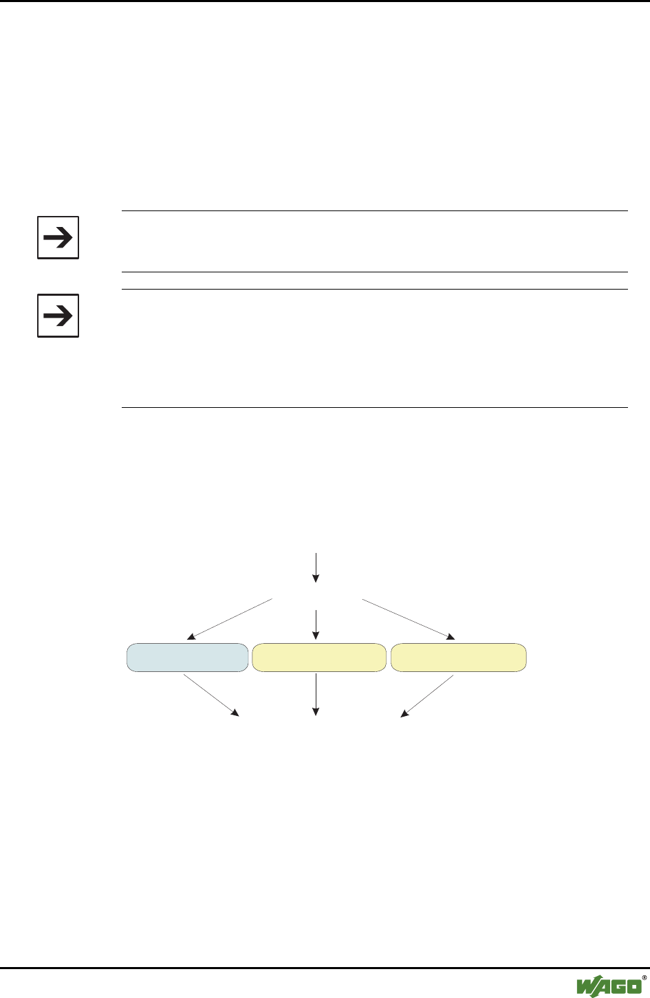
Danger
Always abide by this information to protect persons from injury.
Warning
Always abide by this information to prevent damage to the device.
Attention
Marginal conditions must always be observed to ensure smooth operation.
ESD (Electrostatic Discharge)
Warning of damage to the components by electrostatic discharge. Observe
precautionary measures for handling components at risk.
Note
Routines or advice for efficient use of the device and software optimization.
Additional Information
References for additional literature, manuals, data sheets and web pages.
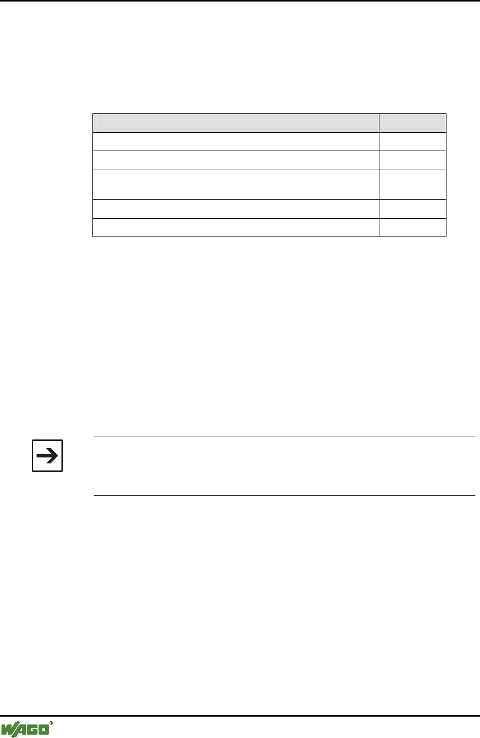
1.3 Number Notation
Number Code Example Note
Decimal 100 normal notation
Hexadecimal 0x64 C notation
Binary '100'
'0110.0100'
within inverted commas,
nibble separated with dots
Important Comments • 9
Safety Notes
WAGO-I/O-SYSTEM 750
I/O Modules
1.4 Safety Notes
Warning
Switch-off the system prior to working on bus modules!
In the event of deformed contacts, the module in question is to be replaced, as
its functionality can no longer be ensured on a long-term basis.
The components are not resistant against materials having seeping and insu-
lating properties. Members of this group include: aerosols, silicones, triglyc-
erides (found in some hand creams).
If it cannot determined that these materials appear in the component envi-
ronment, then additional measures must be taken:
- install of the components in an appropriate enclosure
- handle components only with clean tools and materials.
Attention
Soiled contacts may only be cleaned with ethyl alcohol and leather cloths.
This helps ensure compliance with ESD information.
Do not use any contact spray. The spray may impair the functioning of the
contact area.
The WAGO-I/O-SYSTEM 750 and its components are an open system. As
such, the system and its components must be installed in appropriate hous-
ings, cabinets, enclosures or in electrical operation rooms. Access must only
be provided via key or tool to authorized, qualified personnel.
The relevant valid and applicable standards and guidelines concerning the
installation of switch boxes are to be observed.
ESD (Electrostatic Discharge)
The modules are equipped with electronic components that may be destroyed
by electrostatic discharge. When handling the modules, ensure that the envi-
ronment (persons, workplace and packing) is well grounded. Avoid touching
conductive components; e.g., gold contacts.
1.5 Scope
This manual describes the Bluetooth® RF Transceiver 750-644 from the
WAGO-I/O-SYSTEM 750. Handling, assembly and startup are described in
the manual for the fieldbus coupler/controller. This documentation is therefore
only valid in connection with the appropriate manuals.
10 • I/O Modules
Special Modules
WAGO-I/O-SYSTEM 750
I/O Modules
2 I/O Modules
2.1 Special Modules
2.1.1 750-644 [Bluetooth® RF Transceiver]
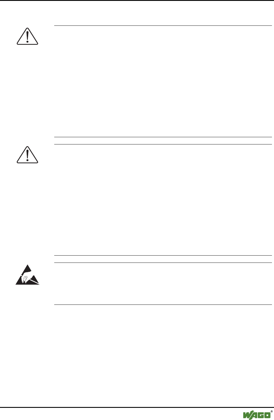
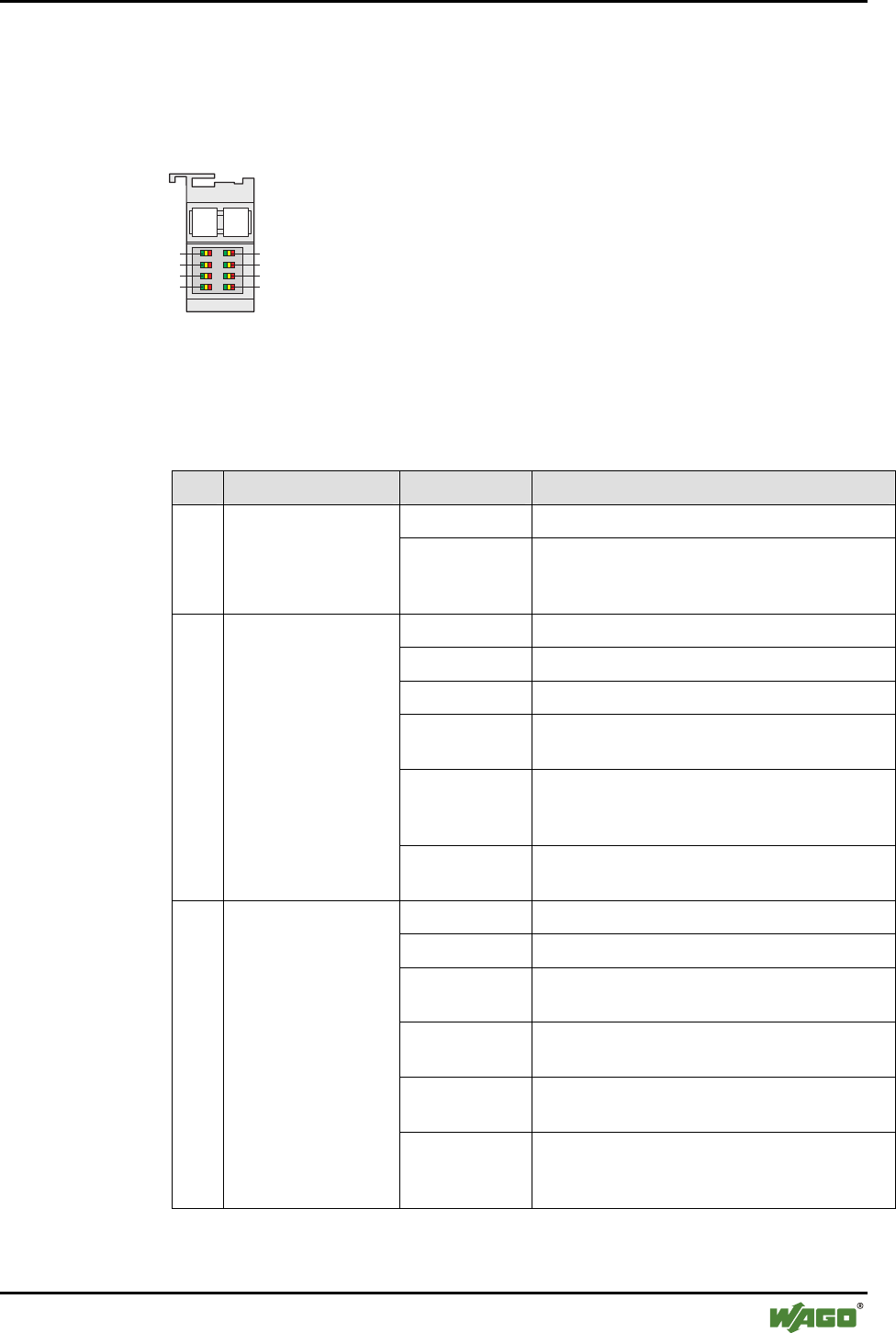
2.1.1.1 View
13 14
750-644
Antenna socket
SMA
Data contacts
Power jumper
contacts
Operational and
connection
status
Figure 1: View g064400e
2.1.1.2 Description
The Bluetooth® RF Transceiver 750-644 (referred to in the following as "Blue-
tooth® module") integrates a Bluetooth® network (piconet) into the WAGO-
I/O-SYSTEM 750. This means that Bluetooth® modules will be installed and
used jointly with the WAGO-I/O-SYSTEM 750 modules in different fieldbus
systems.
The Bluetooth® module facilitates wireless
data exchange within the Bluetooth® piconet.
It can function as the coordinator (referred to
in the following as the "master") or as the
terminal (referred to in the following as the
"slave") depending on the configuration. A
maximum of seven slaves may communicate
with one master (see Figure 2).
Master
Slave
1
Slave
2
Slave
3
Slave
7
Slave
6
Slave
5
Slave
4
Figure 2: Piconet g064403x
The module's configuration (network configuration/process image mapping) is
determined locally via WAGO-I/O-CHECK software.
The current status of the module is displayed by LEDs. While the LEDs asso-
ciated with the function of "slave" signal the quality of the connection, the
LEDs associated with the "master" function show the connection status to
each individually connected slave.

I/O Modules • 11
Special Modules
WAGO-I/O-SYSTEM 750
I/O Modules
The Bluetooth® module is operated in the public domain ISM 2.4 GHz band
and enables wireless data transfer over large distances. If using the WAGO
Antenna 758-912, ranges of up to 1000 meters can be achieved.
The Bluetooth® module 750-644 can be used with the following cou-
plers/controllers of the WAGO-I/O-SYSTEM 750:
Bus System Coupler/Controller Item No. Hardware
version
Software
version
750-301 01 07
750-303 01 07
Fieldbus coupler
750-333 12 from 07
ECO fieldbus coupler 750-343 03 from 06
PROFIBUS
Programmable fieldbus controllers 750-833 12 from 07
Fieldbus coupler 750-306 11 4I
ECO fieldbus coupler 750-346 02 07
DeviceNet
Programmable fieldbus controllers 750-806 02 07
750-337 09 10 Fieldbus coupler
750-338 01 14
750-347 01 04 ECO fieldbus coupler
750-348 01 04
750-837 06 11
CANopen
Programmable fieldbus controllers
750-838 01 11
750-341 03 03 Fieldbus coupler
750-342 04 14
750-841 03 07
ETHERNET
Programmable fieldbus controllers
750-842 04 12
Fieldbus coupler 750-319 07 05 LON
Programmable fieldbus controllers 750-819 08 07
IPC WAGO-IPC 750-870 02 IPC firm-
ware
02.04.
18/0200
Kbus
firmware
01.02.
03(06)
Other couplers/controllers upon request.

12 • I/O Modules
Special Modules
WAGO-I/O-SYSTEM 750
I/O Modules
The version information is contained in the serial number or in the update ma-
trix; both are printed on the right side of the coupler/controller. The serial
number is constructed as follows:
WWYYSWHWFL-Bm1m2m3
Abbrevia-
tion
Description
WW Week of manufacture
YY Year of manufacture
SW Software version of the bus coupler
HW Hardware version of the bus coupler
FL Software version of the firmware loader
- Empty space, no additional meaning
B Designation of the soldered bus connector
m1 Manufacturer of the interface card
m2 Manufacturer of the CPU card
m3 Manufacturer of the power supply card
The m3 designation is not included for bus couplers of the ECO family.
The update matrix is constructed as follows:
NO Work Order Number
DS Date Stamp
SW Software version of the bus coupler
HW Hardware version of the bus coupler
FWL Software version of the firmware
loader
I/O Modules • 13
Special Modules
WAGO-I/O-SYSTEM 750
I/O Modules
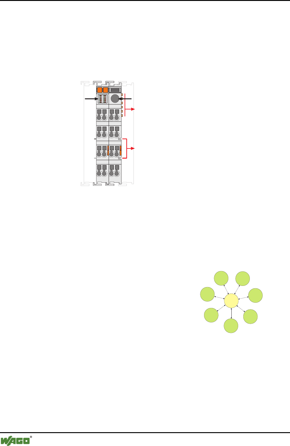
2.1.1.3 Indicators
The LED display must be interpreted differently depending on whether the
Bluetooth® module functions as a master or as a slave (see Sections 2.1.1.3.1
and 2.1.1.3.2).
13 14
1
3
5
7
2
4
6
8
Figure 3: Display Elements g064402x
2.1.1.3.1 Master
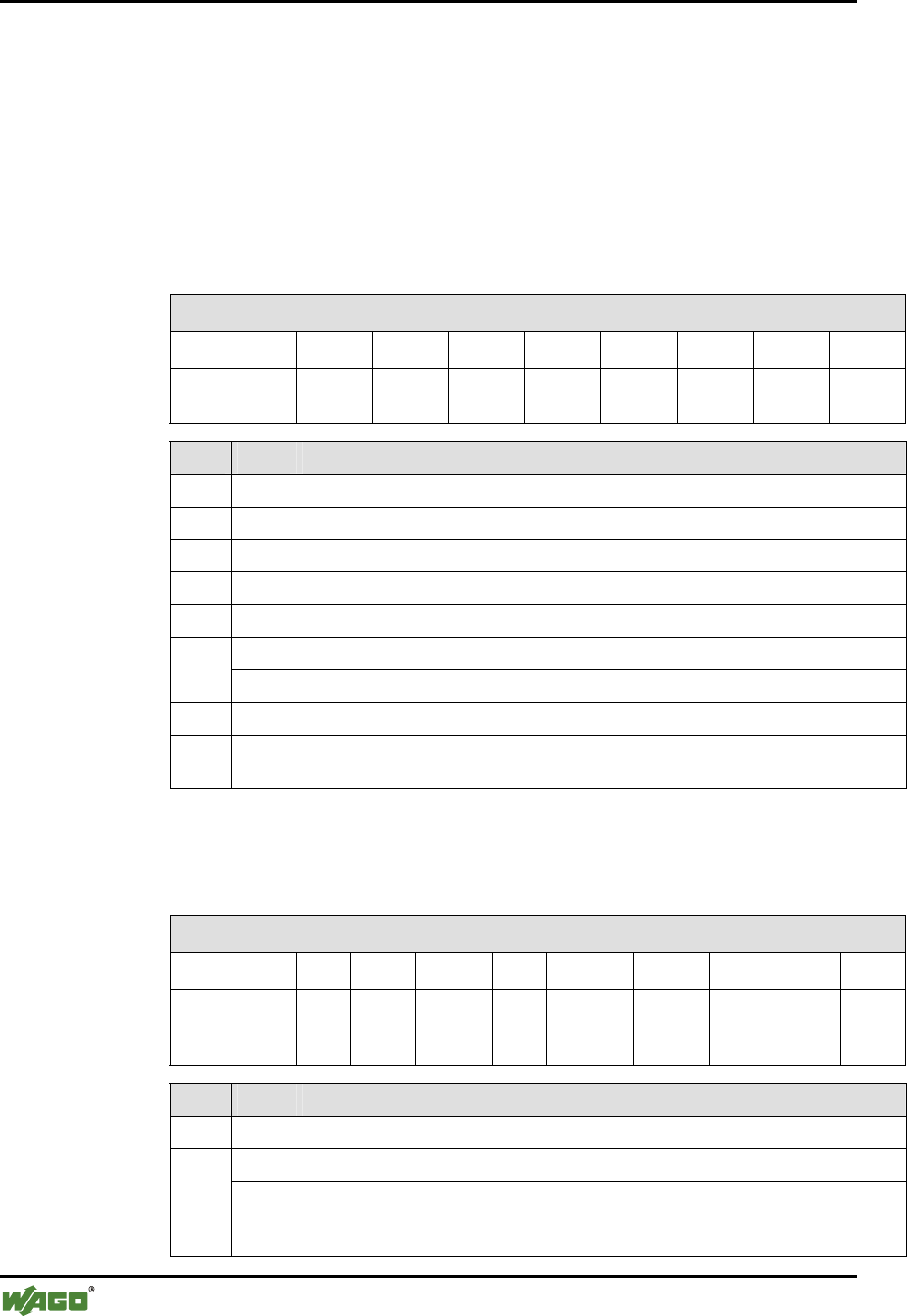
Table 1: LED Master Signals
LED Designation Status: Function
green Normal operation
1 Operation status
indicator red Disruption of the local internal bus connection,
the field voltage or the internal communication
(circuit board)
green Connection to slave(s) established
green flashing Data transfer
off No slave is configured for this slot
yellow flashing Connection to the first slave is being estab-
lished (in communication mode only)
yellow System is configured (in configuration mode
only) or connection to the first slave could not
be established (in communication mode only)
2
Connection display of
the first WAGO slot
(communication
mode) and signaling
in the configuration
mode
red Connection interrupted by error (in communi-
cation mode only)
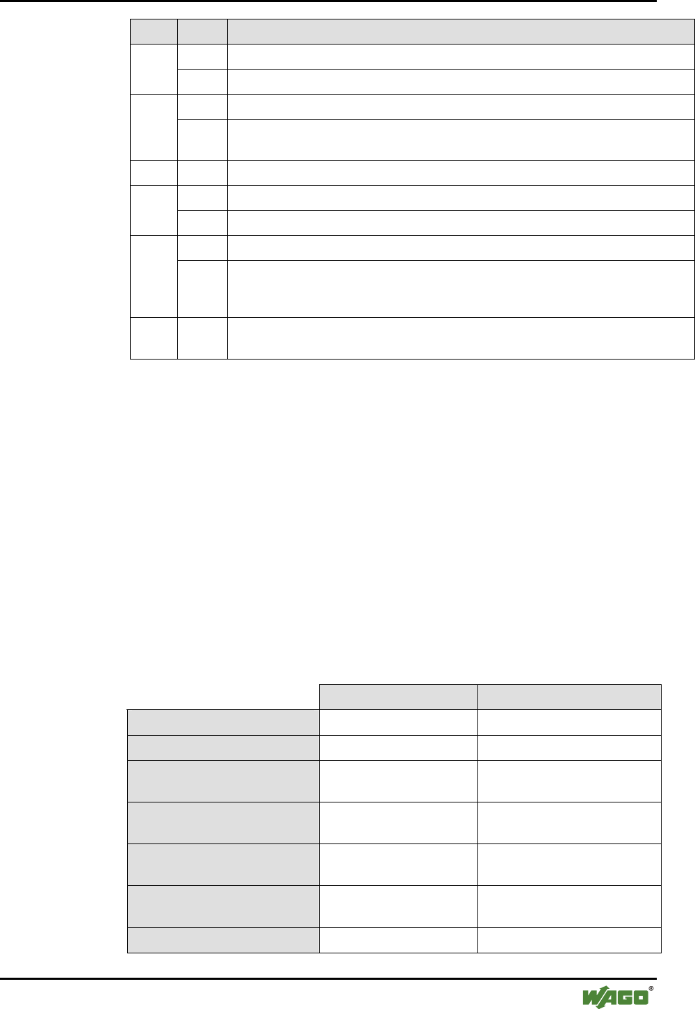
green Connection to slave(s) established
green flashing Data transfer
yellow Unsuccessful connection configuration to slot j
(in communication mode only)
yellow flashing Connection to Slot j is being established
(in communication mode only)
red Connection interrupted by error (in communi-
cation mode only)
3…8
Connection display
for WAGO slots j (j =
2…7) (in communi-
cation mode only)
off No slave is configured for this slot (in commu-
nication mode only) or the system is in con-
figuration mode.

14 • I/O Modules
Special Modules
WAGO-I/O-SYSTEM 750
I/O Modules
2.1.1.3.2 Slave
Table 2: LED Slave Signals
LED Designation Status: Function
green Operating status OK (independent of radio
communication)
1 Operation status indi-
cator red Disruption of the local internal data bus
connection, the field voltage or the internal
communication (circuit board)
green Connection to master established
green flashing Data transfer
off No master is configured for this slot.
yellow flash-
ing
Connection to the master is being estab-
lished (in communication mode only)
yellow System is being configured (in configura-
tion mode only) or connection to the mas-
ter could not be established (in communi-
cation mode only)
2 Connection display for
connected master
red Connection interrupted by error (in com-
munication mode only)
green Signal strength of the received signal good
yellow Signal strength of the received signal very
strong (solution: increase distance of the
device)
Red Signal strength of the received signal weak
(solution: reduce distance of the device).
3, 4
RSSI
Over- or under-
modulation of the
Bluetooth® receiver off There is still no information on the signal
strength of the received signal (there is no
connection or there is a connection only
after a few seconds)
green low bit error rate <10-3
yellow bit error rate 10-2 to 10-3
red high bit error rate > 10-2
(bad transmission line)
5, 6
Connection quality
according to bit error
rate
off no active connection (similar RSSI)
green > 53 lines free (no or negligible third-party
activity in the frequency range)
yellow 39…53 free lines
red < 39 marked as free (massive third-party
activity in the frequency range)
7, 8
Interference display
Number of busy lines
in the 2.4 GHz fre-
quency range
off no active connection (similar RSSI)
I/O Modules • 15
Special Modules
WAGO-I/O-SYSTEM 750
I/O Modules
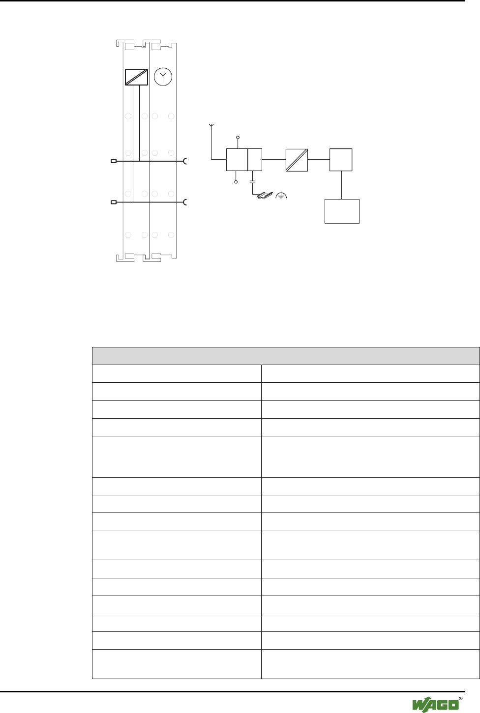
2.1.1.4 Schematic Diagram
750-644
1
2
3
4
5
6
7
8
1
2
3
4
5
6
7
8
0V
+24 V
24 V
0V
SPI
Antenna socket
SMA
Logic
BT-
Module OS
8-segment
LED
display
SPI
Antenna
Figure 4: Schematic Diagram g064401e
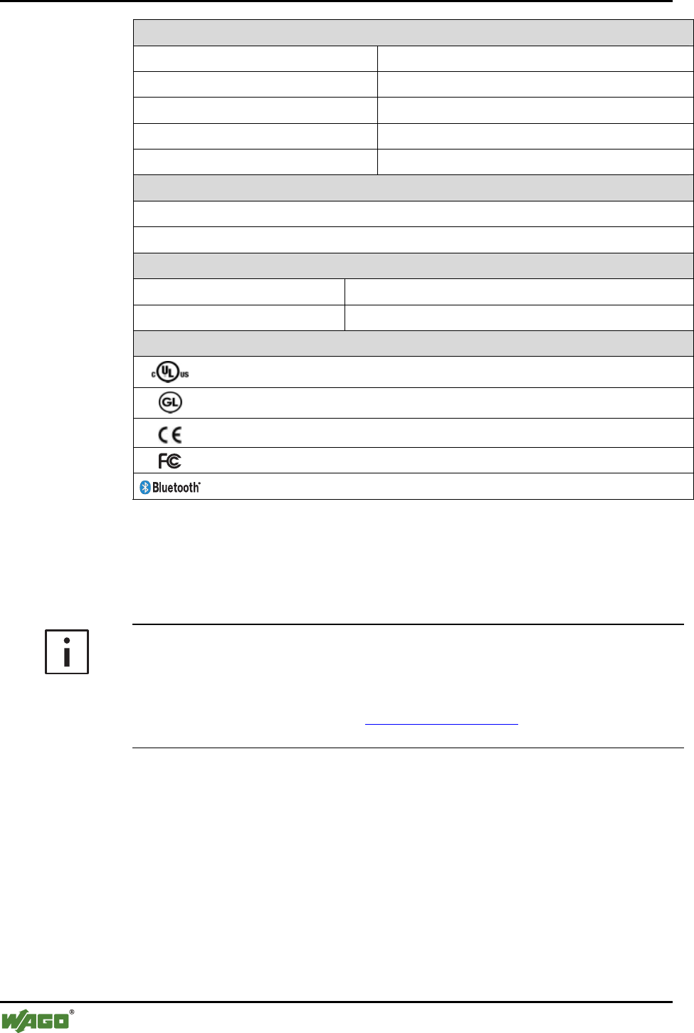
2.1.1.5 Technical Data
Table 3: Technical Data for Bluetooth® Module 750-644
Module-Specific Data
Radio technology Bluetooth® 2.0 + EDR
Topology Piconet (1 master, maximum of 7 slaves)
Coexistence AFH and adaptive transmitting power
Profiles SPP, PAN
Operating modes Communication mode with ad hoc profile for high
connectivity and real-time profile for time-critical
applications and configuration mode
Frequency band public domain, ISM band, 2402…2480 MHz
Transmitting power up to 20 dBm (Bluetooth® Class 1)
Receiver sensitivity -94 dBm
Range (maximum) 1000 m in open air, 100 m in buildings (if using an
external WAGO antenna, item no. 758-912)
Voltage supply (Bluetooth®) through field supply DC 24 V
Voltage supply (internal) via system voltage DC/DC
Current consumption (Bluetooth®) approx. 8 mA, maximum 35 mA
Current consumption (internal) approx. 20 mA
Isolation 500 V (antenna/system)
Data width, internal Configurable to 12, 24, 48 bytes, including 1 con-
trol/status byte
16 • I/O Modules
Special Modules
WAGO-I/O-SYSTEM 750
I/O Modules
Module-Specific Data
Diagnosis (through optical display) Device status, connection status [1]
Diagnosis (through process image) Device status, connection status [1], time monitoring
Configuration WAGO-I/O-CHECK and WAGO-I/O-PRO CAA
Dimensions (mm) W x H x L 24 x 64 [2] x 100
Weight approx. 85 g
Accessories
Miniature WSB Quick marking system
External WAGO antenna, SMA, with magnet base (item no. 758-912)
Standards and directives (see Section 2.2 in manual on coupler/controller)
EMC CE Immunity to interference according to EN 61000-6-2 (2005), EN 61131-2 (2003)
EMC CE Emission of interference according to EN 61000-6-3 (2007), EN 61131-2 (2003)
Approvals (see Section 2.2 in manual on coupler/controller)
CULUS (UL508) (patent pending)
GL (Germanischer Lloyd) (patent pending)
Conformity marking
FCC approval [3]
Bluetooth® approval
[1] Quality of the radio link, signal strength, interference
[2] plus approx. 6.5 mm excess length of the SMA socket
[3] This device complies with Part 15 of the FCC Rules. Operation is subject to the following two condi-
tions: (1) this device may not cause harmful interference, and (2) this device must accept any interfer-
ence received, including interference that may cause undesired operation.
Additional Information
Please refer to the "Overview on WAGO-I/O-SYSTEM 750 approvals" docu-
mentation for detailed information on approvals.
You will find this on the CD ROM "AUTOMATION Tools and Docs"
(item no. 0888-0412) or online at http://www.wago.com under documentation
! WAGO-I/O-SYSTEM 750 ! System Description

I/O Modules • 17
Special Modules
WAGO-I/O-SYSTEM 750
I/O Modules
2.1.1.6 Function Description
Bluetooth® technology defines piconet as a topology consisting of a master
and up to seven slaves. Data can be exchanged between each slave and the
master wirelessly and bidirectionally. Data transfer from slave to slave is pos-
sible indirectly through the master.
The Bluetooth® module implements Bluetooth® Protocol 2.0+EDR and can be
configured as either master or slave. The configuration and activation of spe-
cial functions is done through the mailbox interface described in Appendix
6.1. This is used by the startup tool WAGO-I/O-CHECK and function blocks
of WAGO-I/O-PRO CAA in order to provide the user with simple software-
supported access to the module's full range of functions.
The following networks can be configured with Bluetooth® modules:
• Bluetooth® module as master, up to 7 Bluetooth® modules as slaves (real-
time profile). This real-time scenario is distinguished by an especially low
latency and cycle time.
• Bluetooth® module as master and up to 6 active slaves. In this configura-
tion, Bluetooth® modules configured as slaves and other Bluetooth® de-
vices (e.g. Bluetooth® notebooks or PDAs) can be combined (ad hoc pro-
file). This scenario offers flexible connection possibilities and interopera-
bility.
A Bluetooth® module configured as a master can use up to 46 bytes of data
width for bidirectional data exchange with the slaves. In this case, which proc-
ess data is assigned to which slave can be flexibly configured – the available
data width can be assigned exclusively to one individual slave or be distrib-
uted with freely configurable portions among several slaves.
With Bluetooth® modules, ranges of up to 1000 m can be achieved with inter-
visibility. Good reception is also possible inside buildings, even with the dis-
tribution of network participants in different rooms or floors of the building.
For maximum security, data exchange can be encrypted. Another security fea-
ture of the network is that a piconet configured with Bluetooth® modules al-
lows no penetration by non-authorized devices.
Radio transmission with Bluetooth® is robust, particularly when faced with
outside influences. Thanks to frequency hopping procedures and adaptive
transmitting power, co-existence with other ISM radio technologies (e.g.
WLAN according to IEEE 802.11) is problem-free.
Potential-disturbing influences can be recognized early by the Bluetooth®
module – even before they have a negative effect on communication. Cyclic
and acyclic retrievable diagnostic information that provide information on the
quality of the wireless connection and fulfillment of real-time conditions (in

18 • I/O Modules
Special Modules
WAGO-I/O-SYSTEM 750
I/O Modules
the real-time profile) are offered for this purpose. The most important diagnos-
tic information is also displayed on the device via LEDs, so that the status can
also be directly monitored without additional components at the installation
site.
Additional Information
The Bluetooth® module starts either with the startup tool WAGO-I/O-
CHECK or function blocks of the WAGO-I/O-PRO CAA. The function
blocks for configuration are contained in the library
WAGO_Bluetooth_xx.lib, which you can download from the website
http://www.wago.com under Documentation ! WAGO Software 759 !
WAGO-I/O-PRO ! 759-333 ! Additional Information ! Libraries.
I/O Modules • 19
Special Modules
WAGO-I/O-SYSTEM 750
I/O Modules
2.1.1.6.1 Bluetooth® Class of Device (CoD)
The Class-of-Device (CoD) is a 24-bit field specifying the capabilities of a
Bluetooth® device that is sent with the packet "Frequency Hop Synchroniza-
tion" (FHS) during the device search. According to the Bluetooth® Standard,
the CoD describes the capabilities of the device, thus supporting the search for
devices with certain functionalities.
The CoD enables a rapid assignment of remote devices to different device
categories such as network, audio, telephony. It is divided into the Major Ser-
vice Class (bit 23…13), Major Device Class (bit 12…8) and Minor Device
Class (bit 7…2).
Internal device (sub)classes have been specified for the WAGO module. The
device class for the WAGO-I/O-SYSTEM 750 is represented by bit values 1,
1, 1, in bits 7, 6, 5. It is represented by the bit string 110 for bits 4, 3, 2 (see
Table 4).
Table 4: Configuration of the CoD
Bit
position
Description Suggested values
23-16 Major Service Class
Not given, in accordance with the Bluetooth® specification,
since there is no service that can be uniquely assigned
00000000
15, 14 Reserved 00
13 Limited Discoverable Mode
According to the Bluetooth® specification, the device must
also support the non-discoverable mode
1
12…8 Major Device Class
According to the BT specification, set as "Miscellaneous"
00000
7…2 Minor Device Class (can be used WAGO-specific) Ac-
cording to the Bluetooth® specification: open since the
Device Class is "Miscellaneous"
WAGO-specific use: use of a bit pattern with the following
two-part device class; e.g., to identify the WAGO-I/O-
SYSTEM device subclass; e.g., to identify different prod-
ucts in the device class
111
(= WAGO-I/O-System
750)
bit 7,6,5 device class
110
(= bus module 750-644)
bit 4,3,2 device subclass
1, 0 Reserved, format type 00
The complete CoD for the bus module 750-644 is 0x0020F8hex or
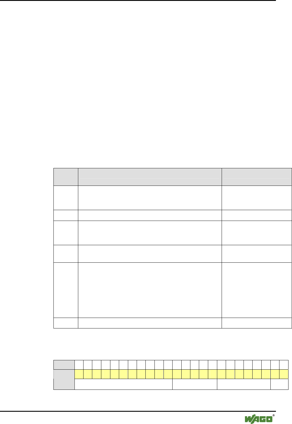
000000000010000011111000bin (see following diagram).
Bit 23 22 21 20 19 18 17 16 15 14 13 12 11 10 9 8 7 6 5 4 3 2 1 0
0 0 0 0 0 0 0 0 0 0 1 0 0 0 0 0 1 1 1 1 1 0 0 0
WAGO-
Device
Class Major Service Class Major Device Class Minor Device Class Type

20 • I/O Modules
Special Modules
WAGO-I/O-SYSTEM 750
I/O Modules
Note
The device subclass can be set by mailbox commands (see Appendix 6.3.5.9).
The CoD can only be influenced by the device (sub)class. Changes in the
Major Service Class or Major Device Class are not possible.
When loading the factory settings, the device class is set to value 7 and the
device subclass to value 6. This results in a CoD of 0x0020F8 for the Blue-
tooth® inquiry.
Many stacks handle devices according to their CoD. Therefore, the set device
(sub)class can influence the function (indirectly through the CoD) in external
devices..
I/O Modules • 21
Special Modules
WAGO-I/O-SYSTEM 750
I/O Modules
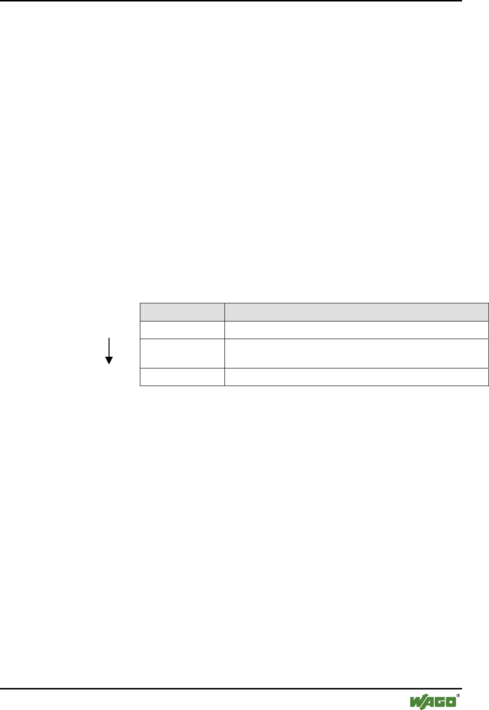
2.1.1.7 Operating Modes
The Bluetooth® module has two different modes available. Each mode fulfills
a certain function:
• Configuration mode
• Communication mode
• in real-time profile
• in ad hoc profile
Note
The Bluetooth® module is in configuration mode when the customer re-
ceives it.
Note
If a Bluetooth® master is operated in the real-time profile, up to 7 Blue-
tooth® slaves can be connected to the master. If the Bluetooth® master is
operated in the ad hoc profile, 6 slaves can be connected. The profile of the
Bluetooth® slaves is irrelevant here. Modes and profiles are a master prop-
erty.
The operating mode is changed (see Figure 5) using WAGO-I/O-CHECK or
function blocks in the WAGO-I/O-PRO CAA and is controlled by mailbox
commands. After the operating mode is changed, the Bluetooth® subsystem is
automatically reset.
Restart
Saved Operation Mode
Configuration Mode Communication Mode
Ad-Hoc Profile
Communication Mode
Real-Time Profile
After changing the saved operation mode via mailbox command,
a restart will be performed automatically.
Figure 5: Operating modes g064404e
22 • I/O Modules
Special Modules
WAGO-I/O-SYSTEM 750
I/O Modules
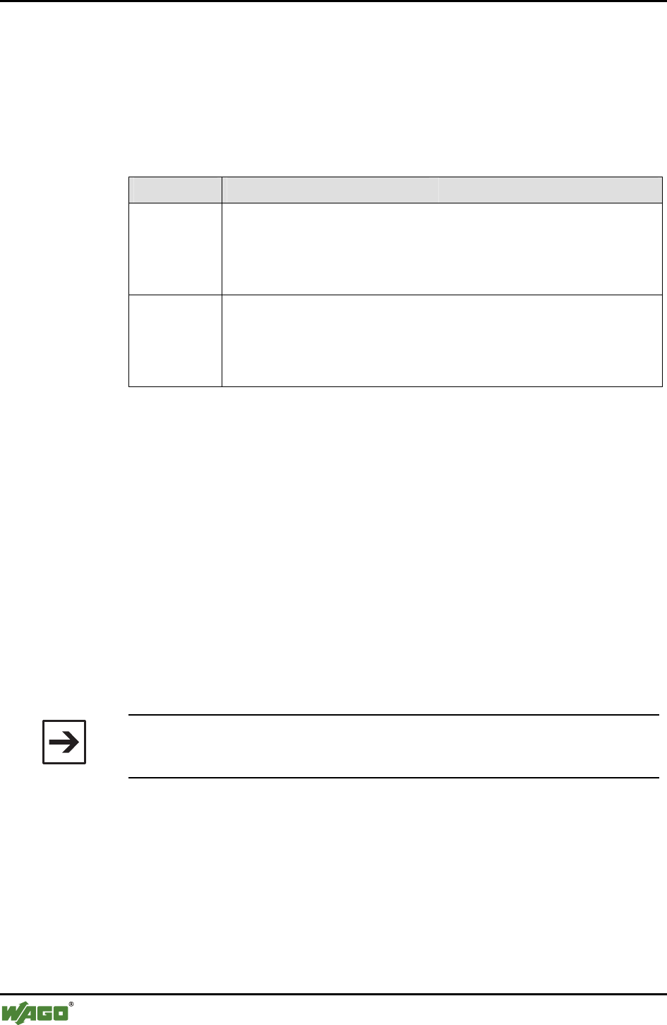
2.1.1.7.1 Time Required for Initialization
Waiting times occur during the initialization of the module
(see Table 5):
Table 5: Waiting times during normal operation of the module
Waiting times for Seconds
Connecting to the first slave ~ 5 [1]
Establishment of connection to a ready-to-receive slave 2-3
Successful establishment of connection by the master to another
slave
2-3 [2]
Unsuccessful attempt to connect to another slave 3-5
Inquiry up to 10.3 [3]
[1] if the slave is ready-to-receive at the conclusion of the master's boot process
[2] the master does not achieve a connection to the slave when attempted
[3] shorter in more than 15 found devices
2.1.1.7.2 Configuration and Communication Mode
The Bluetooth® module operates automatically in configuration mode during
the first operation. If the communication mode with the real-time or ad hoc
profile has already been selected via WAGO-I/O-CHECK, the module's mode
will be changed to the respective profile.
During startup of the module, the last configuration is the one loaded. If this is
not correct; e.g., in the case of an invalid memory structure, the configuration
is overwritten with the factory settings.
Note
The factory settings can also be reset using the mailbox command "SetFac-
torySettings". The individual values for the factory settings can be found in
Table 6.
During initialization, the general error bit 26 is set in the status byte. This
means that no mode has been received and there is no valid process data avail-
able. LED 1 lights up red during initialization (duration approx. 5s).
Once initialization is complete, the module takes on the last configured operat-
ing mode, and LED 1 changes to green. During first operation (factory set-
ting), the module will be in configuration mode following initialization.
In configuration mode, the settings of the module can be configured according
to the desired function, for example by using WAGO-I/O-CHECK. In this
mode, the module can search for other Bluetooth® devices within reception
range and is visible for queries.

I/O Modules • 23
Special Modules
WAGO-I/O-SYSTEM 750
I/O Modules
However, no data exchange takes place. As there is no cyclic process data, the
general error bit continues to be set.
With suitable settings, or immediately after initialization (if already set be-
forehand), the module can change to communication mode.
If the module is started in communication mode, profiles are first loaded and
quality-of-service procedures are prepared. Finally, the connection to precon-
figured devices is configured. Display LED 1 lights up green. The display of
the remaining LEDs depends on the configuration and the communication pro-
file that has been set (see Sections 2.1.1.3.1 and 2.1.1.3.2).
Before the master and slaves exchange process data, they are synchronized to
a common process data size. This is then used from then on for data exchange.
Bootl Loader
Configuration Mode Communication Mode
Real-Time Profile
Communication Mode
Ad-Hoc Profile
Load Operation Mode
Perform Bluetooth module's initialization
Load non-volatile configuration
If configuration is invalid, then load factory settings
Compare non-volatile configuration with factory settings
Correct settings
Initialize Bluetooth stack
Set AccessibleMode ("Not connected") to "Not accessible"
Set Class-of-Device
Set LED (LED 0 green, LED 1-7 off)
Prepare connection establishment
Initialize mailbox
Save process image into module
Set general error bit 2 in status byte to 1
6
Figure 6: Initialization of the configuration and communication mode g064405e

24 • I/O Modules
Special Modules
WAGO-I/O-SYSTEM 750
I/O Modules
2.1.1.7.2.1 Configuration Mode
Mailbox commands are used in configuration mode to configure the Blue-
tooth® module for use. The commands are passed to the Bluetooth® module
and carried out, for example, with WAGO-I/O-CHECK or by using function
blocks of the WAGO-I/O-PRO CAA.
Additional Information
The mailbox commands for configuring the Bluetooth® module can be found
in Appendix 6.1. In Section 3 and Appendix 6.5, the configuration is de-
scribed using WAGO-I/O-CHECK. The Bluetooth®-specific function blocks
of the WAGO-I/O-PRO CAA for configuring the module are contained in the
document "WAGO_Bluetooth_03.lib", is available online at
http://www.wago.com under Documentation ! WAGO Software 759 !
WAGO-I/O-PRO ! 759-333 ! Additional Information ! Libraries.
Table 6 below contains the factory settings. These can be restored and saved
in case of altered configuration by using the mailbox commands "SetFactory-
Settings" (except for Bluetooth® device name). A device name is overwritten
by the assigned mailbox command.
Table 6: Factory settings for the Bluetooth® module
Parameter Setting
Bluetooth® device name WAGO-750-644
IP 192.168.0.2
Subnet Mask 255.255.255.0
Gateway 192.168.0.1
Device role slave
Operating mode configuration mode
Mailbox cascade
Encryption active
Authentication with password
Standard password 0000
Quality of Service (QoS) disabled
Class of Device 0x0020F8
Time for reconfiguration of connection 30 seconds
Authorized devices none (all lists are initialized with "0")
Linked devices none (all lists are initialized with "0")
Process image sizes of the up to 7 slaves in the
master
10,0,0,0,0,0,0 bytes (used when changing
the device role to "master")
I/O Modules • 25
Special Modules
WAGO-I/O-SYSTEM 750
I/O Modules
2.1.1.7.2.2 Block Transfer
The module parameters can be individually read and written using mailbox
commands (see Appendix 6.1). It is also possible, as an alternative, to upload
or download the complete configuration in 512-byte blocks. For example, a
created or read out configuration block can be used to set up and configure all
additional slaves.
512-byte blocks are sent. The transfer is opened each time by the group
DLD_START described in Appendix 6.3.2.1 and closed with DLD_END.
With each DLD_CONT command, one element of the block is transferred. Af-
ter transferring one 512-byte block, the module verifies the checksum.
After the copying process has been successfully completed, the module con-
firms the DLD_END command by sending the calculated checksum and the
return 0x00 (OK).
The format of the configuration block transferred by means of the DLD com-
mands is described in 6.4.
Table 7: Block transfer process using DLD commands
DLD commands Explanations
DLD_START Configuration of the block transfer
n x DLD_CONT Transfer of the 512-byte blocks in n* consecutive elements
(* depends on the mailbox size, see Appendix 6.3.2.2)
Procedure
DLD_END End of the block transfer, testing of the checksum
The exact mode of operation of the commands "DLD_START",
"DLD_CONT" and "DLD_END" can be found in Appendix 6.3.2.
2.1.1.7.2.3 Communication Mode – Real-Time Profile
In the real-time profile, signals can be monitored in real-time. The cycle and
error message time is assured making this profile especially suited for time-
critical applications such as system monitoring. In case of an error, the system
can be stopped immediately. The real-time network is invisible to Bluetooth®
networks. Real-time capable masters only exchange data with directly con-
nected slaves.
Within the module, time intervals between different, repeating events are
monitored by Watchdog and other monitoring mechanisms. In case of distur-
bances, warnings/errors are signaled, depending on the type of disturbance, or
the module is automatically restarted.
26 • I/O Modules
Special Modules
WAGO-I/O-SYSTEM 750
I/O Modules
If there is an existing connection between WAGO devices, the time between
the received packets is measured. If there is a significant timeout, warnings or
error messages are sent (see Table 8). The typical time response is signifi-
cantly more high performance than the upper limits given here for warnings
and errors.
Table 8: Time responses for Bluetooth® module
Name Value
BTCOM_
WARNTIME
master, 1 slave linked:
master, 2…5 slaves linked:
master, 6 slaves linked:
master, 7 slaves linked:
slave:
40 ms
20 ms * (number of end devices + 1)
240 ms
280 ms
280 ms
BTCOM_
ERRORTIME
master, 1 slave linked:
master, 2…5 slaves linked:
master, 6 slaves linked:
master, 7 slaves linked:
slave:
80 ms
40 ms * (number of end devices + 1)
480 ms
560 ms
560 ms
If the time limits cannot be adhered to, warnings or error messages are issued
via acyclic diagnosis functions (LED displays, see Section 2.1.1.3) or cycli-
cally through the status byte of the process image (see Section 2.1.1.8.1.1).
For optimal time response, a valid piconet configuration must exist. If the
master cannot establish a connection to all slaves, the attempt to reintegrate
these devices leads to interruptions in data communication (see also "SetRe-
connectionTimePeriod", Appendix 6.3.5.34). To prevent this, you can tempo-
rarily remove defective devices from the piconet. No change in configuration
is required for removing the devices; simply set the affected devices to "not
linked" in the "real-time" communication profile. The master then no longer
integrates these devices during this time.
With the next change in operating mode or restart, the master will again try to
connect to all devices.
Note
Only connections to WAGO devices can be configured in the real-time pro-
file.

I/O Modules • 27
Special Modules
WAGO-I/O-SYSTEM 750
I/O Modules
2.1.1.7.2.4 Communication Mode – Ad Hoc Profile
"Ad hoc communication" is the "spontaneous" connection of devices. The
main feature is the problem-free connection of very different types of devices.
Therefore, the requirements for partner devices are less strict, making real-
time communication impossible when using this profile.
Note
In the ad hoc profile, you can connect up to 6 slaves with one master (up to 7
slaves in the real-time profile).
Note
Adherence to time limits (see Section 2.1.1.7.2.3) is not monitored in the ad
hoc profile, making this profile ideal for less time-critical applications.
WAGO devices can be connected with each other and with third-party Blue-
tooth® devices in the ad hoc profile. The Bluetooth® protocols SPP & PAN are
available for this purpose (see Table 14).
2.1.1.7.2.4.1 Connecting WAGO Devices with External Devices
The Bluetooth® module from WAGO can be connected with other WAGO
Bluetooth® modules via L2CAP. These connections are especially fast and are
subject to various reliability and reaction speed requirements. Slaves that sup-
port this form of connection are referred to as WAGO devices in this docu-
ment.
By using PAN and SPP, devices that do not fulfill these requirements can also
be used. These devices, which actually control the exchange of the process
image, but not the real-time requirements, are called "external devices".
When configuring the wireless connection of an external Bluetooth® device
(e.g., PDA) to a WAGO Bluetooth® device, note that external devices must
have a valid protocol header embedded in their Bluetooth® packets. This must
be configured according to the following pattern (see Table 9):
28 • I/O Modules
Special Modules
WAGO-I/O-SYSTEM 750
I/O Modules
Table 9: Configuration of the Bluetooth® Packet
Channel name Length
in bytes
Value Description
CHANNEL_SELECT 1 0000 0001
(0x01)
Virtual channel selection, always 0x01
STATUS_FLAGS 1 0000 0000
(0x00)
Status bits, always 0x00 for external devices
STATUS_DATA_SIZE 1 xxxx xxxx Data length in bytes, according to "cutoff"
(see Section 2.1.1.8.1.2)
DATA[1] 1 xxxx xxxx 1st byte of process data
... ... xxxx xxxx ...
DATA[n] (=cutoff) 1 xxxx xxxx nth (last) byte of process data
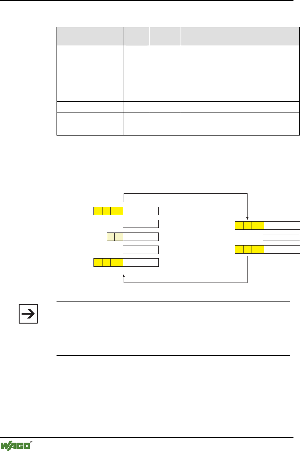
This header is automatically added in WAGO (see Figure 7).
Bluetooth
®
Bluetooth
®
WAGO Device
Header is added and removed automatically
Data
External Device
Radio transmission
Radio transmission
01 00 Data
Cutoff
length
01 00 Data
Local data
Header must be
created from the device
01 00 Data
Cutoff
length
Data
Data
C/S int Data
01 00 Data
Control/status byte
are not transmitted
Header is added
automatically
Control/status byte
are added
Header is removed
automatically
Header is removed
from the device
Local data
Header must be added and removed from the device
Cutoff
length
Cutoff
length
Figure 7: Adding the header in data packets of external devices g064406e
Note
Missing data in the protocol header may lead to termination of the connec-
tion. Therefore, prepend the 3-byte channel information (0x01 and 0x00 and
field length) to the data to be transferred if you would like to send from an
external device to a WAGO device.
WAGO devices add the header automatically.

I/O Modules • 29
Special Modules
WAGO-I/O-SYSTEM 750
I/O Modules
2.1.1.7.2.5 Configuration of the Wireless Connection
End devices are passive during configuration of the connection. Masters are
also passive if the connection is configured through SPP or PAN by external
devices. During the configuration of a connection, the status of a remote node
(if it is authorized and entered on the external devices list) is tested. Connec-
tions are actively configured only if the Bluetooth® module is operating as a
master in the real-time or ad hoc profile. The module can be connected
through the PAN profile using port 3501.
2.1.1.7.2.6 Net Forming
"Net forming" is the configuration of Bluetooth® modules for the purpose of
defining a Bluetooth® network.
The role of the Bluetooth® module - master or slave - is established in the con-
figuration mode (see Section 2.1.1.7.2.1). The devices that are to be included
in the list of permitted devices is also established by entering the respective
device MAD IDs in WAGO-I/O-CHECK. A search can serve as an additional
aid here. Then, out of all the entered MAD IDs, those devices to which a con-
nection is actually to be configured are marked as "linked". The prerequisite
for a successful configuration is a bilateral authorization, both from the master
for the slaves and from each slave for the master. Then the new settings are
downloaded into the module.
If you select "real-time" or "ad hoc" in the communication profile (see Section
2.1.1.7.2.3 to 2.1.1.7.2.4), a search for already configured Bluetooth® devices
will be performed first. The list of all authorized slaves is processed. The
module attempts to actively connect (master) with connected devices or to ac-
cept connections from them (slave). If a device is not marked as "linked" in
the list, connection attempts are refused by the device (slave) or no attempt to
connect to this device is made (master). Even if one or more devices are not
connected, data exchange with the remaining participants begins immediately
after the connection attempt.
The module attempts to configure the complete network at regular intervals.
Devices that cannot be reached temporarily are also reconnected as soon as the
connection is re-established. It is irrelevant whether a connection has never
been configured or whether it failed due to power failure at the site of the re-
mote node, for example (can be set using "SetReconnectionTimePeriod").

30 • I/O Modules
Special Modules
WAGO-I/O-SYSTEM 750
I/O Modules
Note
Wireless packets are only accepted and forwarded to the slave if a bilaterally
authorized wireless connection exists; i.e., the Bluetooth® MAC address of
the communication partner is entered in the table of permitted devices and the
table entry has been activated for the creation of a connection (linked) in the
master and slave. Since a maximum of seven remote devices can be linked,
the entry of authorized MAC addresses is independent of the process of link-
ing/delinking.
I/O Modules • 31
Special Modules
WAGO-I/O-SYSTEM 750
I/O Modules
2.1.1.8 Process Image
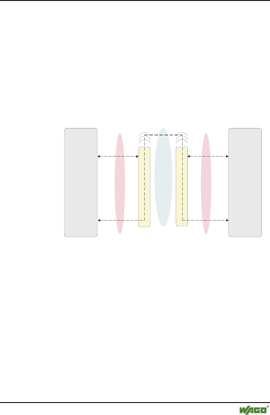
Process data communication using the Bluetooth® protocol is cyclic. Data is
requested, processed in a fixed sequence and exchanged between master and
slaves.
For configuration, diagnosis and register communication, data is transmitted
acyclically between modules and locally connected applications - but not
wirelessly (see Figure 8).
Both the cyclic and acyclic communication share a transmission channel - the
process image.
Fieldbus
WAGO-I/O-CHECK
WAGO-I/O- CAAPRO
Fieldbus
WAGO-I/O-CHECK
WAGO-I/O- CAAPRO
Bluetooth
®
Module
(cyclic)
Process image
Process image
Configuration,
Diagnostics
(acyclic)
Configuration,
Diagnostics
(acyclic)
Radio Channel
Bluetooth
®
Module
Process data exchange
Figure 8: Cyclic and acyclic communication g064407e
The size of the process image for the Bluetooth® module can be set as a fixed
size, 12, 24 or 48 bytes. The process image contains 2 bytes of control infor-
mation consisting of a control / status byte and an internally used byte.
The mailbox is superimposed in a size of 6, 12 or 18 bytes on the Bluetooth®
process data as long as the control bit (0x20) is set.
Mailbox and process image sizes are set either via startup tool WAGO-I/O-
CHECK or by using WAGO-I/O-PRO CAA over the address 0 in the parame-
ter channel.
Table 10 explains the breakdown of the data in process data and register com-
munication.
32 • I/O Modules
Special Modules
WAGO-I/O-SYSTEM 750
I/O Modules
Table 10: Process data and register communication
Process data communication
Mailbox switched on Mailbox switched off
Register Communication
Control /status
(1 byte long, from byte 0)
Control /status
(1 byte long, from byte 0)
Control /status
(1 byte long, from byte 0)
Used internally
(1 byte long, from byte 1)
Used internally
(1 byte long, from byte 1)
Used internally
(1 byte long, from byte 1)
Register data
(2 bytes long, from byte 2 to 3)
Mailbox
(Acyclical data,
6…18 bytes long,
from byte 2 to n)
Process data
(Cyclical data,
0…32 bytes long,
from byte n + 1 to m)
(Pay attention to the valid-
ity of the data!)
Process data
(Cyclical data,
0…32 bytes long,
from byte 2 to m) Invalid data
(from byte 4 to m)
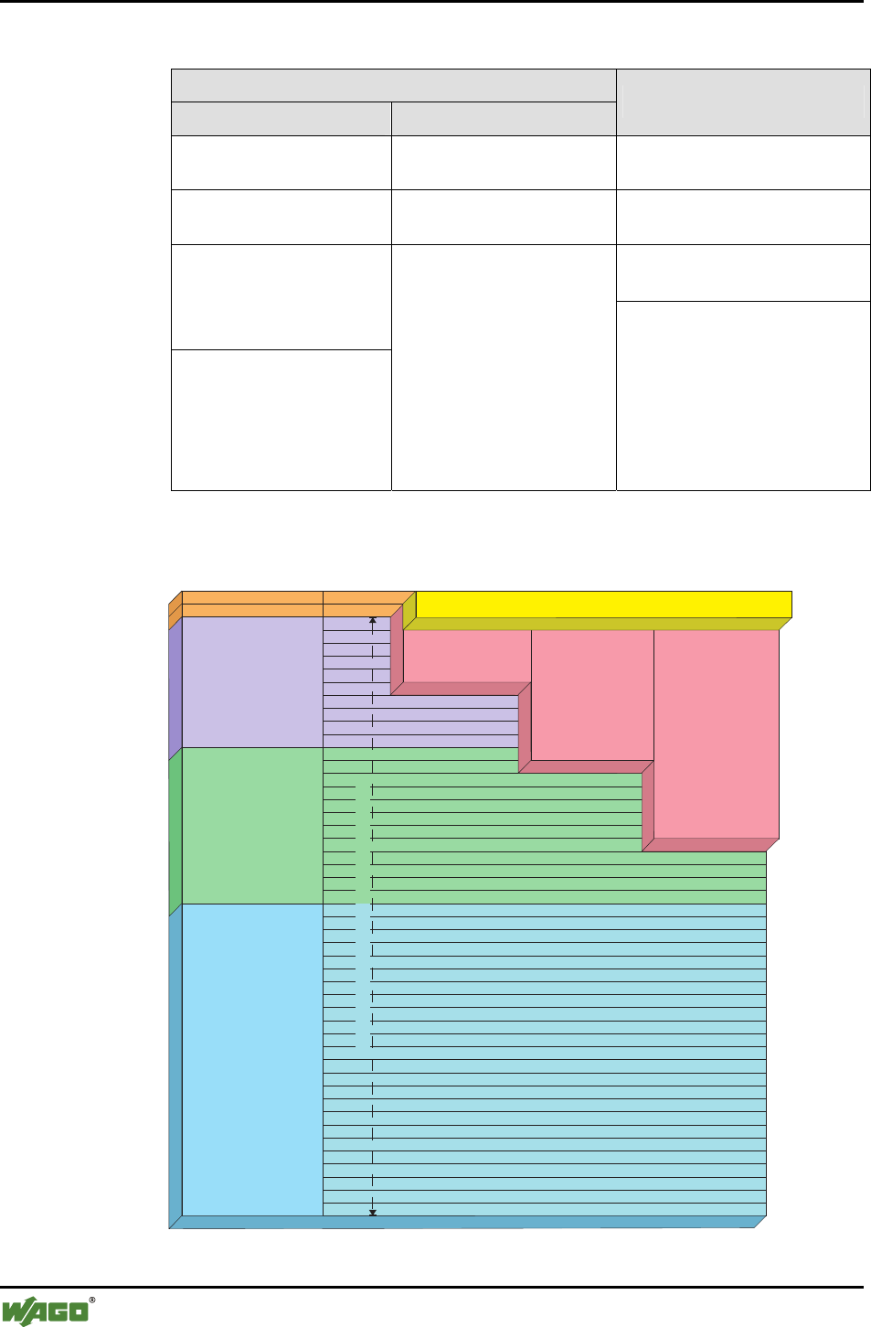
The possible settings with regard to the overall process image and mailbox
size are explained in the following graphic.
0
1
2
3
4
5
6
7
8
9
10
11
12
13
14
15
16
17
18
19
20
21
22
23
24
25
26
27
28
29
30
31
32
33
34
35
36
37
38
39
40
41
42
43
44
45
46
47
Mailbox
6 byte
= 0x20Control/status
Mailbox
18 byte
= 0x20Control/status
Mailbox
12 byte
= 0x20Control/status
Register data 2 byte Control/status = 0x80
Process data length
12 byte
Process data length
24 byte
Process data length
48 byte
Control/status byte
Reserved
Process data 12-46 byte Control/status = 0x00
Figure 9: Superimposition of the mailbox and register data on the process data g064408e
I/O Modules • 33
Special Modules
WAGO-I/O-SYSTEM 750
I/O Modules
If the mailbox bit (bit 25 in the control byte) is set to masked mailbox (see
Table 10), the mailbox is masked by the cyclical data field. The masked field
is then no longer valid; however, the non-masked field continues to be up-
dated and may be used. If the mailbox flag is not set, the mailbox is masked
and the cyclical data field is valid. The desired setting is confirmed by mirror-
ing in bit 25 of the status byte.
Note
Consider the validity of the data areas in your application program
(WAGO-I/O-PRO CAA).
To activate register communication (see Table 10), bit 27 in the control byte
is set. Resetting this bit switches the register communication off again. The se-
lected setting is mirrored in bit 27 of the status byte. The register data is cov-
ered with an offset and a size of 2 bytes by the respective cyclic or acyclic
(covered by the mailbox) memory area.
Attention
During register communication, the mailbox and process data are invalid!
In the following Sections 2.1.1.8.1 and 2.1.1.8.3, the different types of com-
munication between Bluetooth® modules are described. You can find an over-
view in Table 11.
Table 11: Overview of types of communication
Type of communication Configuration of the control / status byte
Process data communication
without mailbox
Control byte
Status byte
no bit set (0x00)
no bit set (0x00)
(contains additional diagnostic informa-
tion, see Section 2.1.1.8.1.1)
Process data communication
with mailbox
Control byte
Status byte
Bit 25 set (0x20)
Bit 25 and 26 set (0x60)
(contains additional diagnostic informa-
tion, see Section 2.1.1.8.1.1)
Register Communication Control byte
Status byte
Bit 27 set (0x80)
Bit 27 set (0x80)
(contains additional information, e.g. the
register number, see Section 2.1.1.8.3.1)
34 • I/O Modules
Special Modules
WAGO-I/O-SYSTEM 750
I/O Modules
2.1.1.8.1 Process Data Communication
During active process data communication, cyclic process data is exchanged
between master and slaves.
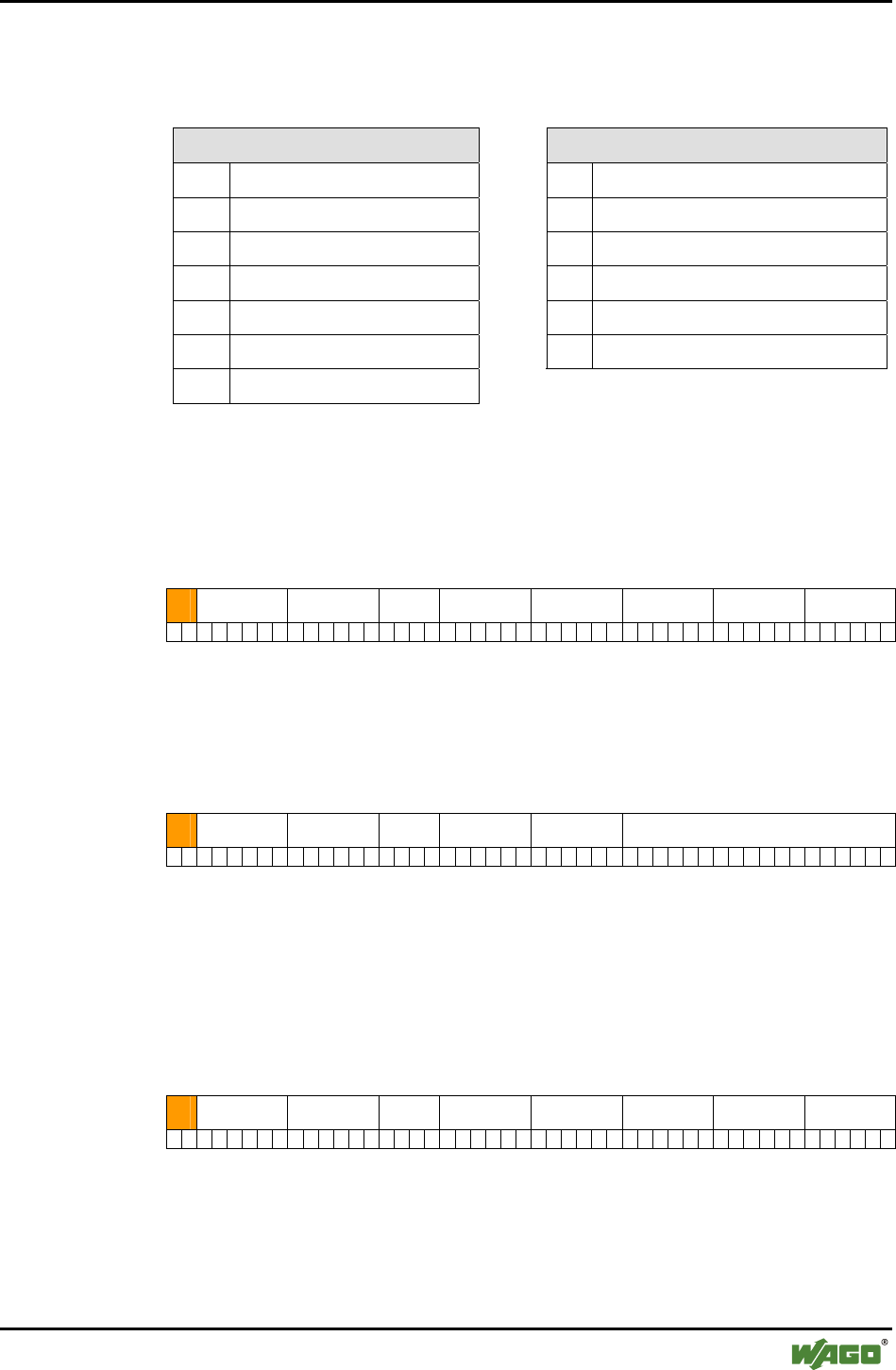
2.1.1.8.1.1 Configuration of the Control and Status Bytes
In process data communication, the control byte is configured as follows:
Table 12: Configuration of the control byte
Control byte
Bit 27 2
6 2
5 2
4 2
3 2
2 2
1 2
0
Value/
Description 0 0 Mailbox 0 0 0 0 0
Bit Value Description
20 0 Reserved (always 0)
21 0 Reserved (always 0)
22 0 Reserved (always 0)
23 0 Reserved (always 0)
24 0 Reserved (always 0)
0 Mailbox masked 25
1 Mailbox unmasked
26 0 Reserved (always 0)
27 0 During process data communication, always 0
(switch between process data communication and register communication)
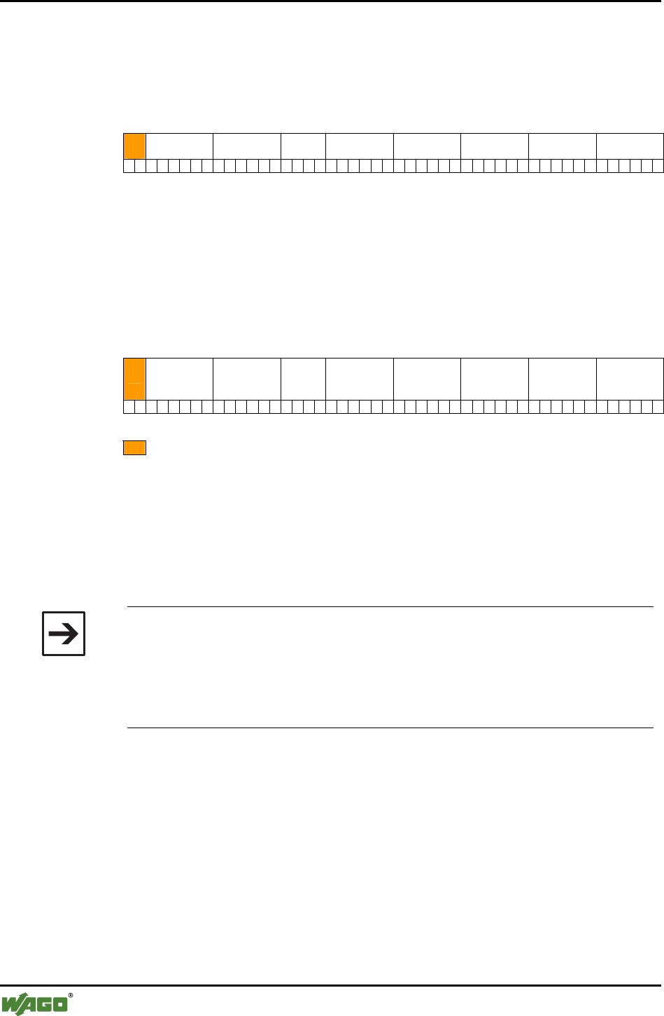
In the status byte, messages, warnings and errors are signaled as follows:
Table 13: Configuration of the status byte
Status byte
Bit 27 2
6 2
5 2
4 2
3 2
2 2
1 2
0
Value/
Description 0
Gen-
eral
error
Mailbox 0 General.
warning
Mailbox
(remote)
Monitoring of
time behavior 0
Bit Value Description
20 0 Reserved (always 0)
0 No warning
21 1
Warning of obsolete process data. Indicates that no packet has been received
from the other party for a connection within the time defined as the error limit
(for times, see table from 2.1.1.7.2.3)
I/O Modules • 35
Special Modules
WAGO-I/O-SYSTEM 750
I/O Modules
Bit Value Description
0 Mailbox of the connected device covered
22 1 Mailbox of the connected device uncovered (warning of obsolete data)
0 No warning
23 1 Warning; e.g., if after the expiration of a defined time limit for warning mes-
sages, no packet has been received from the other party
24 0 Reserved (always 0)
0 Mailbox masked (confirmation of the bus module)
25 1 Mailbox unmasked (confirmation of the bus module)
0 Wireless connection is established
26 1
Warning of non-existence of process data or invalid process data, for example in
configuration mode, during a restart or in the case of an interrupted wireless con-
nection
27 0
During process data communication, always 0 (confirmation of the bus module)
(switch between process data communication and register communication)
2.1.1.8.1.1.1 Connecting WAGO Devices and External Devices
Slaves are divided into two groups: WAGO devices and external devices. The
WAGO devices use the real-time profile and the connection over L2CAP. Ex-
ternal devices can be connected with the master using the ad hoc profile by
SPP profile or through PAN. Both groups are therefore administered in sepa-
rate tables, even if they must be considered together with regard to simultane-
ous connections. The table for WAGO devices can accept up to seven entries.
Up to six devices are administered for external devices. A maximum of seven
simultaneous connections can exist at the same time, independently of how
many devices are listed in the tables of authorized devices using their MAC
addresses (see Table 14 and Table 15).
Table 14: Differences between WAGO devices and external devices
WAGO devices External devices
Table WAGO_DEVICE (0x20) EXTERNAL_DEVICE (0x10)
Protocols L2CAP SPP, PAN
Profile of the master for a
connection
Real-time, ad hoc Ad hoc
Maximum number of
slaves/slots per master
7 (6 in the ad hoc profile) 6
Process image
Module bus (in bytes)
10, 22, 46
(Process image – 2)
device-specific
Data width of wireless trans-
mission
per slot, according to the
"cutoff"
per slot, according to the "cut-
off"
Initiator of the connection Master Slave
36 • I/O Modules
Special Modules
WAGO-I/O-SYSTEM 750
I/O Modules
If WAGO and external devices in different modes are connected with a
WAGO master, the following guidelines apply for communication with each
other (see Table 15):
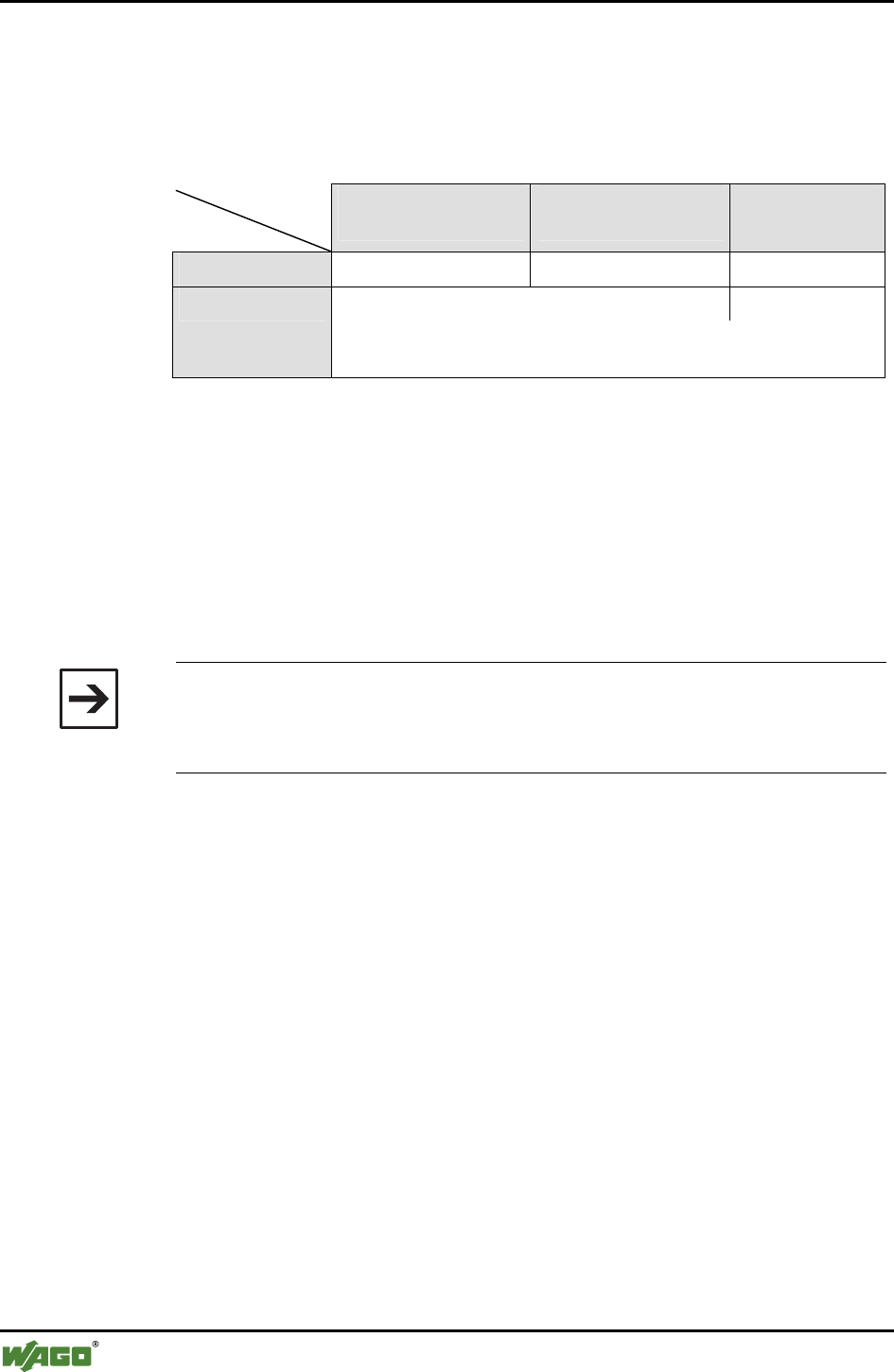
Table 15: Possible connection of a master with WAGO or external slaves
Slave
Master
WAGO BT module
Real-time profile
WAGO BT module
Ad hoc profile
External device
Real-time profile up to 7 devices - -
up to 6 devices up to 6 devices
Ad hoc profile
In the ad hoc profile, a maximum of 7 devices can be active at the
same time, but there are always 13 slots available for configuration.
In the master, slots 1 through 7 correspond to the entries in the table of
WAGO devices. In the ad hoc profile, slots 8 through 13 are added with the
table entries for external devices.
In the ad hoc profile, connections to a maximum of seven slaves are estab-
lished. Of these, a maximum of six can be (see Table 15) WAGO slaves and a
maximum of six can be external devices. By using up the tables for external
and WAGO devices, process image areas can be configured for up to 13 slots
in the master.
Note
When changing to the ad hoc profile, care must be taken that the real-time
device is not connected to slot 7. If a device with a "cutoff" greater than zero
is configured, slot 7 is filled with zeros in the process image.
In the slave, the process image always contains only one slot in which the con-
figured master is unmasked. The width of a slot is determined by the "cutoff"
of this slot.
I/O Modules • 37
Special Modules
WAGO-I/O-SYSTEM 750
I/O Modules
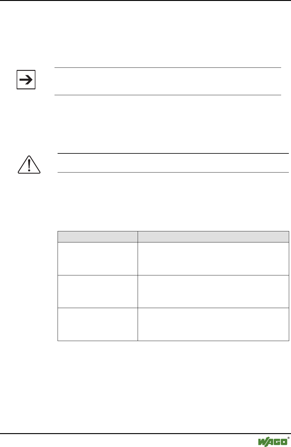
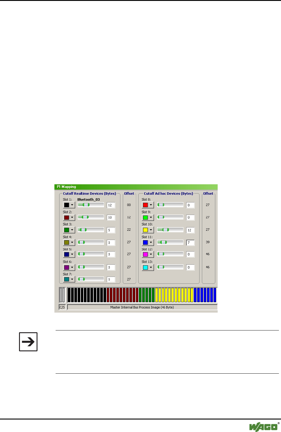
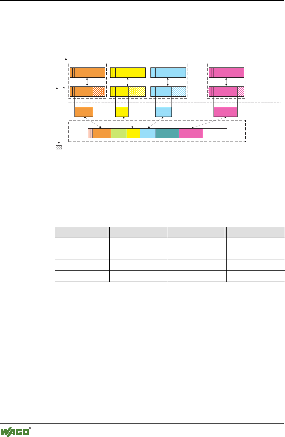
2.1.1.8.1.2 Process Image Mapping of the Master
Up to seven slaves can be connected to one master. The process images of
these slaves are mapped in the process image of the master.
The process image consists of a fixed number of virtual plug-ins for the Blue-
tooth® master and slaves, designated as slots. Each slot is assigned a defined
share of the process image by means of the process image mapping. One slave
can be configured for each slot, to which data can be transmitted in the area
assigned to this slot. A maximum of 6 or 7 devices can be active at one time.
The slots can occupy a length of up to 46 bytes in the master (see Figure 10).
If only one slave is connected to the master, this slave can take advantage of
the entire available size of the master.
In WAGO-I/O-CHECK (configuration mode), the user determines which and
how much data the individual slaves currently occupy in the process image of
the master.
The local process image is constructed similar to that in Figure 9. For data ex-
change between devices, the available area after byte 2 is further divided.
Figure 10: Mapping of the slaves in the master process image g064409e
Note
The size of the slave process images in the process image of the master can
be changed, not only by WAGO-I/O-CHECK, but also of the command "Se-
tRemoteSize". The operation is symmetrical for the data stream entering or
exiting the master.
After changing to communication mode, the data exchange between master
and slaves begins. The master requests data that the slave sends back over the
Bluetooth® network.
38 • I/O Modules
Special Modules
WAGO-I/O-SYSTEM 750
I/O Modules
In doing so, the slaves only send "excerpts" of their process data to the master.
The size of these "excerpts" is determined by "cutoff" in the configuration
mode. The command "cutoff" is symmetrical for the data stream entering and
exiting the master. The current data to be read and written, which are assigned
slots in the master's process image, remain (see Figure 11).
Data Direction Slave Master
Data Direction Master Slave
Cut off by cutoff, is not transmitted
Process image
Radio transmission
(without control/status byte )
Slave A Slave B Slave C
Master
Slave X
...
...
...
Slot1 Slot 2 Slot 3 Slot 4 Slot 5 Slot 6
...
Figure 11: Process image mapping between master and slaves g064410e
The following example (see Table 16) shows that both slots in the process im-
age not occupied by slaves (see slot 1 and 4) as well as slots that are not visi-
ble due to a "cutoff" of 0 (see slot 4) can be visible. A "cutoff" of 0 is inde-
pendent of whether a device has been set up for the slot or not.
Table 16: Example of a slot configuration
Slot Slave Cutoff Offset
1 - 4 0
2 "Pump" 6 4
3 "Valve" 10 10
4 - 0 20
I/O Modules • 39
Special Modules
WAGO-I/O-SYSTEM 750
I/O Modules
In an additional example, we describe how the slot configurations behave in
conjunction with a configuration of the master (process image size = 48
bytes):
WAGO Table External Table
W1 permitted cutoff = 6 E1 linked cutoff = 6
W2 linked cutoff = 6 E2 linked cutoff = 6
W3 free cutoff = 0 E3 linked cutoff = 6
W4 linked cutoff = 4 E4 free cutoff = 0
W5 linked cutoff = 6 E5 free cutoff = 0
W6 free cutoff = 0 E6 free cutoff = 0
W7 linked cutoff = 6
Resulting process image in the master (ad hoc profile)
• 13 available slots, 5 of these with a width of 0 (W3, W6, E4, E5, E6)
• Since no connection is established with W7, the slot remains filled with ze-
ros
W1 W2 W4 W5 W7 E1 E2 E3
0 48
Resulting process image in the master (real-time profile)
• 7 available slots, 2 of these with a width of 0 (W3, W6)
W1 W2 W4 W5 W7 free
0 48
E1 has been removed in the configuration mode (ad hoc profile)
• "AllowRemoteDevice" with external Table E1 and MAD-ID: 0:0:0:0:0:0
• After removing E1, the slot is filled with zeros. No data are transmitted to
this slot
W1 W2 W4 W5 W7 00000... E2 E3
0 48
40 • I/O Modules
Special Modules
WAGO-I/O-SYSTEM 750
I/O Modules
W6 has been processed in the configuration mode (ad hoc profile)
• "AllowRemoteDevice" with MAC address of W6
• "Cutoff" for slot 6 raised from 0 to 6
W1 W2 W4 W5 W6 W7 E2 E3
0 48
Connection to E2 is disconnected (ad hoc profile)
• UnbindRemoteDevice or end device discontinues the connection
• Slot assignments are not changed
• The last data is retained until the next reboot
W1 W2 W4 W5 W7 E1 E2 (Data
obsolete)
E3
0 48
Control/status byte and internally used byte
The complete process image is first transmitted from the slave to the master. If
the slave has received a process image of the master, it sends only those bytes
that are still visible after the "cutoff" from this point on. It is always the visible
portion of the process image only, which is not truncated by "cutoff", that is
transmitted from the master to the slave.
Note
Missing data in the protocol header may lead to termination of the connec-
tion. Therefore, prepend the 3-byte channel information (0x01 and 0x00 and
field length) to the data to be transferred if sending from an external device to
a WAGO device. WAGO devices add the header automatically (see Section
2.1.1.7.2.4.1).
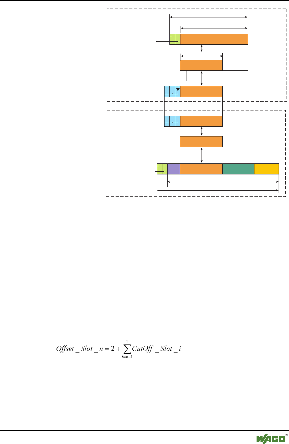
I/O Modules • 41
Special Modules
WAGO-I/O-SYSTEM 750
I/O Modules
12, 24, 48 Byte
Slave
Master
10, 22, 46 Byte
Slot1 Slot 2 Slot 3 Slot 4
Cutoff
12, 24, 48 Byte
Control/status byte
Byte used internally
Radio transmission
Bluetooth®
protocol header
will be transmitted
Master's process image
Slave's process image
Usable process data (local)
Bluetooth® protocoll
Importing of individual
information (cutoff)
Bluetooth®
protocol header
Cutoff size entry
into header
Assignment of slave process image
to a slot within the master process image
Control/status byte
Byte used internally
Figure 12: Transmission of additional information in the Bluetooth® protocol header g064411e
The "cutoff" can be separately set for each slot with the command "SetRe-
motePiSize" (see Appendix 6.3.4.1).
To set up specific devices for slots, use the command "AllowRemoteDevice"
(see Appendix 6.3.5.26) together with the MAC address of the target device. If
no device is to be set up for the slot, use instead of a valid MAC address the
address 0:0:0:0:0:0. Only those slots in which valid MAC addresses are en-
tered can be activated (linked) (see Appendix 6.3.5.28, BindRemoteDevice).
The configuration of the display of a slot in the process image by "cutoff" is
completely independent of this.
The number of bytes before the start of a slot is called its offset. The offset of
a slot in the process image of the master may vary depending on the configu-
ration. The offset for any slot can be calculated with the following formula:
The two additional allowed bytes are the control/status byte and the internally
used byte. All commands that change the slot width or the assignment of de-
vices to slots can only be used in the configuration mode. The position of the
data of a remote device in the local process image is therefore unchanged in
communication mode.
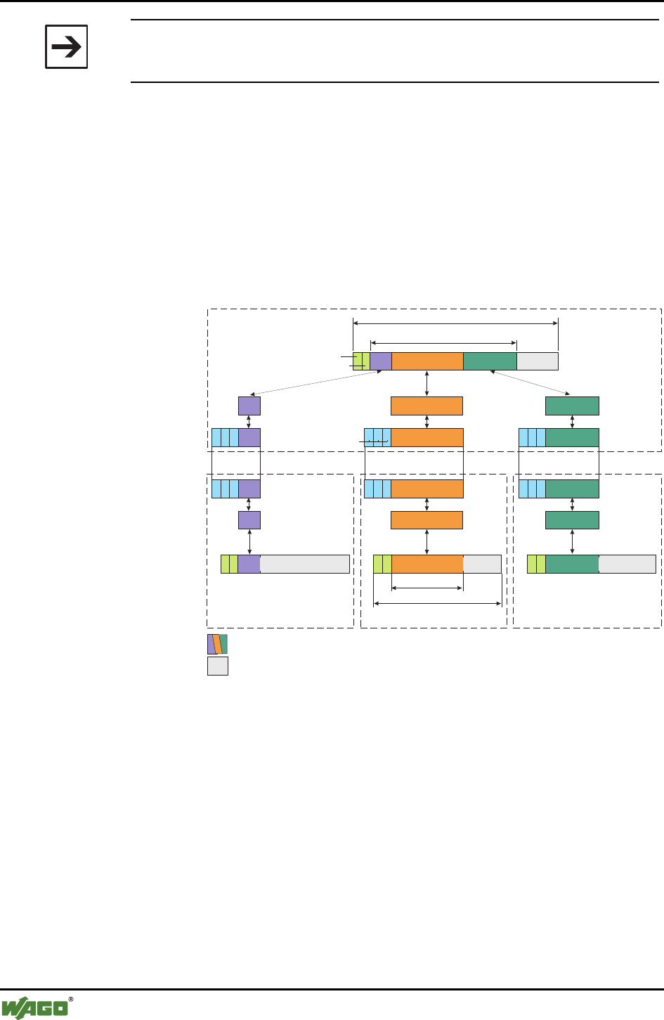
42 • I/O Modules
Special Modules
WAGO-I/O-SYSTEM 750
I/O Modules
Note
The offset begins with the 3rd byte of the process image (after the con-
trol/status and internal bytes).
2.1.1.8.1.3 Process Data Mapping of the Slaves
The process image of the master occupies only one slot (the first) in the proc-
ess image of the slave. This first slot uses the entire process image size. In this
case, it does not matter which cutoff size was set for slot 1 in the slave. The
configuration of the cutoff is only valid in the master and is not utilized in the
role as slave. Only those bytes that lie within the cutoff allowed by the master
for the slave are updated in this slot, however.
Bluetooth®
protocol header
Slots to be transmitted
Master's process image
Control/status byte
Byte internally used
Bluetooth® protocol
Master cutoff
process image of Slave B
Radio transmission
Process data, updated via Bluetooth®
Unassigned areas of the process image
Slave A Slave B Slave C
12, 24, 48 Byte
Slot1 Slot 2 Slot 3
12, 24, 48 Byte
Slot 1 Slot 1Slot 1
Master
Slaves
Figure 13: Process image mapping of the slave g064413e

I/O Modules • 43
Special Modules
WAGO-I/O-SYSTEM 750
I/O Modules
2.1.1.8.1.4 Up-to-Dateness of the Process Image
WAGO master and WAGO slave regularly send their current process image
independently of changes. If one party, (master or slave) no longer receives a
new process image, the most recently received data remains current. If the
master receives no new process image from a WAGO slave over a longer pe-
riod of time, it signals this in its status byte (in the real-time profile, see Sec-
tion 2.1.1.8.1.1).
The master also sends a current process image to external devices; however,
the updating of received data is not tested. There is no signaling in the status
byte as with WAGO devices. The recency of the data from external devices is
therefore not certain.
2.1.1.8.1.5 Aging Due to break off of Connection
If a connection ends, regardless of whether intended (by the command "Un-
bindRemoteDevice", see Appendix 6.3.5.29) or by the failure of the remote
device, the slot configured for this device is retained. The last transmitted data
remain in this slot until the connection is re-established.
In WAGO devices, the failure of a connection is signaled by LEDs and the
status byte. In the case of an intended cutoff of the connection, obsolete data is
not signaled as an error. When the connection is re-established, the parts of the
process image configured for this slot are overwritten with current data re-
gardless of the previous status.
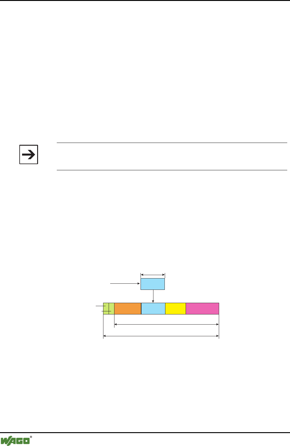
44 • I/O Modules
Special Modules
WAGO-I/O-SYSTEM 750
I/O Modules
2.1.1.8.2 Mailbox Communication
Modules with mailbox functionality have an acyclic communication channel
(mailbox) in the process image. The data exchange between module and ap-
plication can be significantly expanded over this channel without enlarging the
process image. The mailbox masks cyclic data in the process image if active.
Depending on the module function, the remaining cyclic data is valid and
available during mailbox communication (see page 32, Figure 9).
All relevant functions and configuration steps for communication with other
Bluetooth® devices are mapped by mailbox commands. This make knowledge
of the most important mailbox commands vital for the manual configuration of
the module through the process image. To configure the module using
WAGO-I/O-CHECK, however, this knowledge is not necessary; all module
functions are accessible via graphical interface.
Note
Please pay attention to the instructions for the use of modules with mailbox
functionality in the respective handbook for your coupler/controller.
2.1.1.8.2.1 Aging of Data by the Mailbox
If the mailbox is activated, it covers a part of the process data. Thus, select
data is covered in the input process image(see Figure 14). Data not covered is
not updated either if at least 1 byte of the respective slot of the mailbox is cov-
ered. After the mailbox is deactivated, the current data from the last received
process image is immediately displayed.
Cutoff size
Received process image
Slot is updated
Process images of the remote devices
Input process image
Without Mailbox
Control/status byte
Byte internally used Slot 1 Slot 2 Slot 3 Slot 4
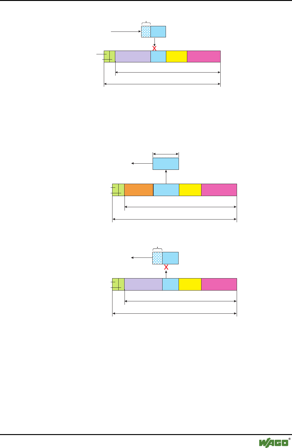
I/O Modules • 45
Special Modules
WAGO-I/O-SYSTEM 750
I/O Modules
Slot is not updated since
superposed by mailbox
Process images of the remote devices
Input process image
Superposed
by mailbox
With Mailbox
Received process image
Control/status byte
Byte internally used Mailbox Slot 2 Slot 3 Slot 4
Figure 14: Unmasking of the mailbox response in the input process image g064414e+89e
Process data in the output process image is also masked when the mailbox is
activated. As long as the mailbox is active, the affected data areas are no
longer updated. Unmasked data areas continue to be updated.
Send process image to slave
Update process image
Process images of the remotedevices
Output process image
Control/status byte
Byte used internally
Process image is not updated
since superposed by mailbox
Process images of the remotedevices
Superposed by mailbox
With Mailbox
Send process image to slave
Cutoff size
Without Mailbox
Output process image
Control/status byte
Byte used internally Slot 1 Slot 2 Slot 3 Slot 4
Mailbox Slot 2 Slot 3 Slot 4
Figure 15: Unmasking of the mailbox response in the input process image g064415e
The cyclic transmission of process images is not influenced by an active mail-
box. Received data may be aged, however, by a superimposed mailbox. This
is signaled to the remote device in the Bluetooth® header. The remote device
confirms this status, on its end, in the control/status byte (see Section
2.1.1.8.1.1). If the mailbox bit of the remote slave is set, then all (in the slave)
or parts (in the master) of the displayed process data may be aged.
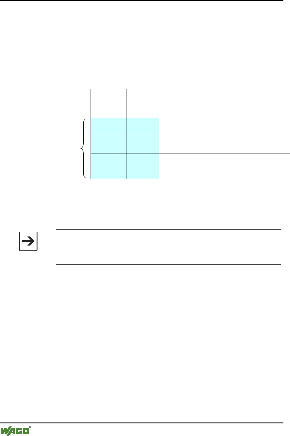
46 • I/O Modules
Special Modules
WAGO-I/O-SYSTEM 750
I/O Modules
2.1.1.8.2.2 Setup
If bit 5 in the control byte is set, the mailbox is unmasked. It begins with byte
3 of the process image after the control/status byte and the internal byte. It
covers, depending on the set size, 6, 12 or 18 bytes of the process data (see
page 32, Figure 9). In this area, the data is interpreted as mailbox data, so that
commands (opcodes) can be sent here.
The setup of the data in the mailbox is always identical:
Byte 0 Control/status byte
Byte 1 Internal
byte
Byte 2 Opcode The opcode identifies the command and determines
the interpretation of the parameters.
Byte 3 Toggle
byte
Byte 3 contains the toggle bit (bit 7) and the return
value in the response.
Set up
of the
mailbox Bytes 4…19 Parameters The interpretation of the parameters depends on the
opcode. The number of parameters is dependent on
opcode and mailbox size.
Figure 16: Setup of the mailbox
This basic form applies for query and response alike. The query is entered in
the output process image of the module, the response is extracted from the in-
put process image.
Note
The content of the mailbox is only interpreted by the module if the opcode is
changed or the toggle bit inverted. A change in the parameters does not lead
to any processing of mailbox content.
If bit 25 of the control byte is set, there is a mailbox query (see Table 17). Un-
used bytes of the query are not utilized.
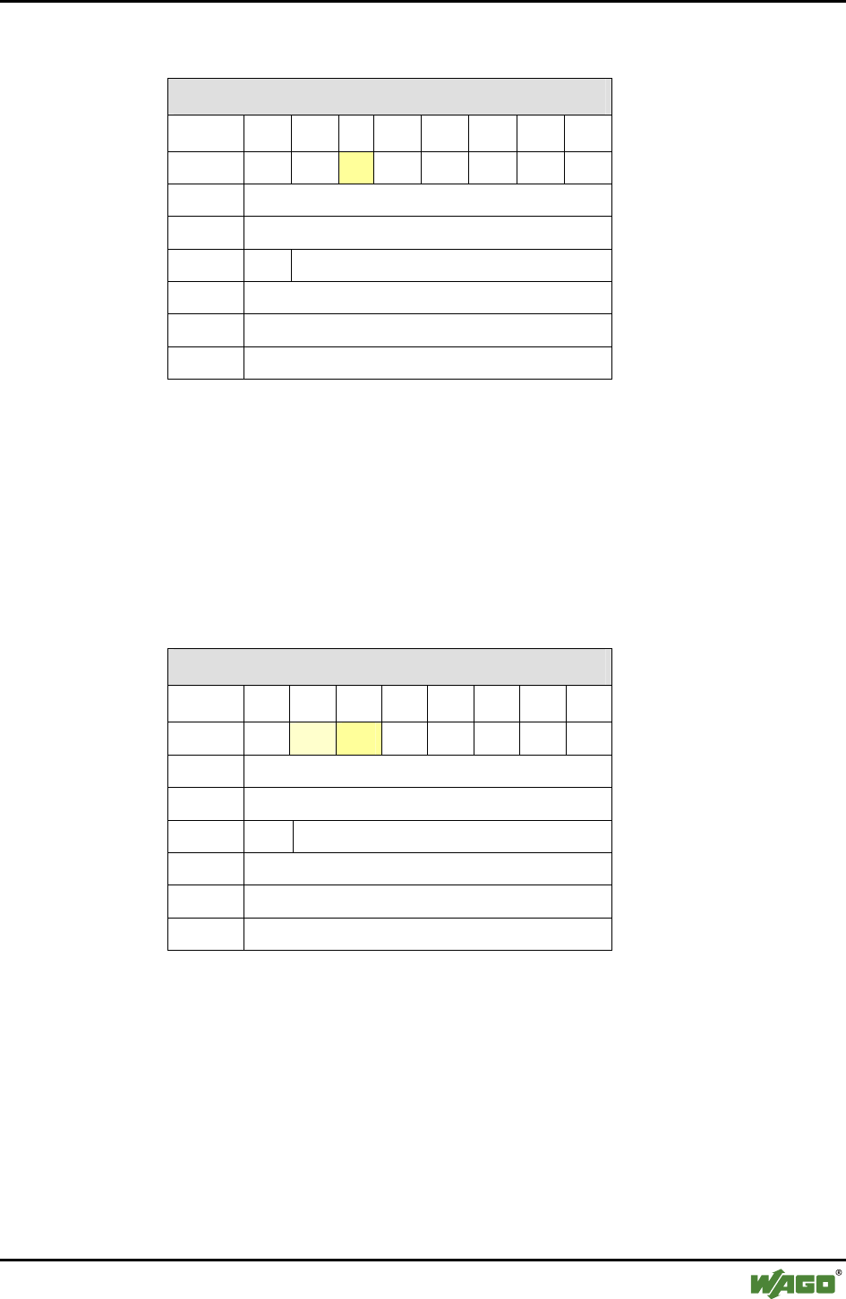
I/O Modules • 47
Special Modules
WAGO-I/O-SYSTEM 750
I/O Modules
Table 17: Mailbox query
Mailbox query
Byte 27 2
6 2
524 2
3 2
2 2
1 2
0
0 0 0 1 0 0 0 0 0
1 -
2 Opcode
3 T -
4 Query parameter byte 0
… …
max. 19 Query parameter byte 15
Opcode
T
- command code of the mailbox request
- toggle bit - A mailbox request is started with a change.
In the mailbox response, bits 25 and 26 of the status byte are set. Bit 25 con-
firms the activated mailbox.
Bit 26 can be set. This indicates a general error since the modules are in con-
figuration mode and have no valid network configuration. Unused bytes of the
response are set to 0.
Table 18: Mailbox response
Mailbox response
Byte 27 2
6 2
5 2
4 2
3 2
2 2
1 2
0
0 0 0/1 1 0 0 0 0 0
1 -
2 Opcode (mirrored)
3 T Return value
4 Response parameter byte 0
… …
max. 19 Response parameter byte 15
Opcode
T
Return value
- mirrored command code of the mailbox request
- toggle flag - A mailbox request is confirmed by a change.
- Status/error of the mailbox request
The mailbox is unmasked if there is an existing wireless connection to the lo-
cal device; this is signaled to the other party by bit 22. This warns of poten-
tially aged data due to the uncovered mailbox (see Section 2.1.1.8.2.1).

48 • I/O Modules
Special Modules
WAGO-I/O-SYSTEM 750
I/O Modules
2.1.1.8.2.3 Access Procedure
Unmasking the mailbox by setting bit 5 in the control byte is required for exe-
cuting mailbox commands. The module confirms this by setting bit 5 in the
status byte. In order to execute a mailbox command, query parameters and the
opcode of the command must be written in the output process image. Since a
change in the opcode and/or the toggle bit is a trigger for the processing of a
command, the query parameters must be written into the output process image
either at the same time or previously.
The module confirms the processing of the command by inserting a response
telegram in the mailbox area of the internal data bus input data. The response
evaluation must occur at the same point at which the opcode and toggle bit are
identical with the query contents; i.e., these are mirrored. The processing time
in the module may require several bus cycles. Some special commands trigger
a longer process (e.g., search for devices within range). For these commands,
the module's response confirms that the process has begun. The results of
longer lasting processes can be queried after completion by other commands.
The toggle bit is necessary for executing two mailbox commands with the
same opcode (but possibly differing parameters) one after the other.
Note
The use of mailbox commands implements a confirmed service. The module
provides information via return value on the successful execution of the
command or errors that occur. If errors occur, it may be that not all response
bytes contain valid data.
The following diagram (see Figure 17) describes the request and processing of
a mailbox command. The process data are displayed as follow in this case:
[ parameter 0-x | toggle | opcode | internal byte | control/status byte ]
Initially, any process data may be present in the output and input process im-
age. After entering the opcode and/or toggle bit, as well as switching the mail-
box on using bit 25 in the control byte, the mailbox command is transmitted
and a query is started. In the input process image, the query is received, proc-
essed and confirmed with bit 25. This confirmation and the new process data
are sent to the output process image. Here, the data is evaluated. The next
command can be transmitted.
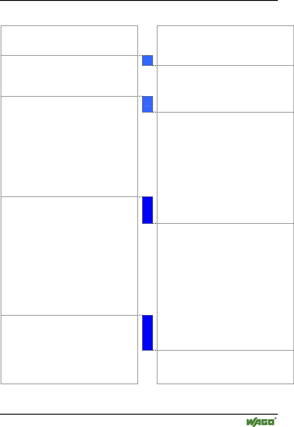
I/O Modules • 49
Special Modules
WAGO-I/O-SYSTEM 750
I/O Modules
PIO Processing Times PII
Cyclically updated process data
[XX.XX.XX.XX.XX.XX.XX.XX.XX.XX].00.00
Cyclically updated process data
[XX.XX.XX.XX.XX.XX.XX.XX.XX.XX].00.00
Switching on the mailbox, mailbox command IDLE
(0x00)
[XX.XX.XX.XX].[00.00.00.00].[00.00].00.20
Response to mailbox command IDLE
(0x00)
[XX.XX.XX.XX].[00.00.00.00].[00.00].00.60
Request for mailbox command GetLinkSignal-
Strength (0xD7)
[XX.XX.XX.XX].[00.00.00].[20].[00.D7].00.20
This queries the receive signal strength for the first slot.
The mailbox includes:
Opcode 0xD7
Toggle byte 0x00
Argument 0x20 (Slot 1)
Filling byte 0x00 (for unused mailbox bytes)
..
Response to mailbox command GetLinkSignal-
Strength
(0xD7)
[XX.XX.XX.XX].[00.00.00].[1B].[00.D7].00.60
Response to the query:
Opcode (mirrored) 0xD7
Toggle bit, return value 0, 0x00
Argument 0x1B (value of the signal
strength of the queried
slot)
Filling byte 0x00 (for unused mailbox
bytes)
Request for mailbox command GetLinkSignal-
Strength
(0xD7)
[XX.XX.XX.XX].[00.00.00].[28].[80.D7].00.20
This queries the receive signal strength with a false
argument. The mailbox includes:
Opcode 0xD7
Toggle byte 0x80 (toggle bit set to execute new
command)
Argument 0x28 (invalid)
Filling byte 0x00 (for unused mailbox bytes)
.
Response to mailbox command GetLinkSignal-
Strength
(0xD7)
[XX.XX.XX.XX].[00.00.00.00].[83.D7].00.60
Response to the query:
Opcode (mirrored) 0xD7
Toggle bit, return value 1, 0x03
Argument No argument since invalid
call up
Filling byte 0x00 (for unused mailbox
bytes)
Since an invalid index was used with 0x28, there are no
arguments in the response.
Cyclically updated process data (mailbox masked)
[XX.XX.XX.XX.XX.XX.XX.XX.XX.XX].00.00
Cyclically updated process data (mailbox masked)
[XX.XX.XX.XX.XX.XX.XX.XX.XX.XX].00.00
Figure 17: Example of mailbox communication g064416d

50 • I/O Modules
Special Modules
WAGO-I/O-SYSTEM 750
I/O Modules
2.1.1.8.2.4 Mailbox Commands and Return Values
In Appendix 6.1, you will find an overview of all mailbox commands sorted
according to groups and opcodes (see Appendix 6.1.1) or alphabetically ac-
cording to the names of the commands (see Appendix 6.1.2).
A detailed description of each command can be found in the reference to Ap-
pendix 6.3.
If a mailbox command is executed, the command is confirmed. The return
value is transmitted in byte 3 of the process data. Section 2.1.1.8.1.1 summa-
rizes the possible return values.
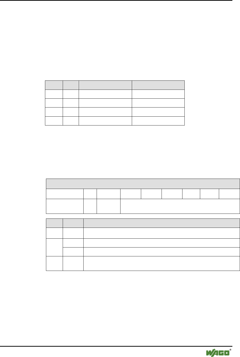
I/O Modules • 51
Special Modules
WAGO-I/O-SYSTEM 750
I/O Modules
2.1.1.8.3 Register Communication
Register communication allows direct access to 64 module registers. These
serve exclusively for module configuration on the lowest level. Register com-
munication is active if bit 27 is set.
The contents of the register follow the control/status and internal bytes in
D0/D1 of the input/output process image:
Table 19: Setup of the process image during register communication
Byte Word Input process image Output process image
0 0 Control byte Status byte
1 Internal byte Internal byte
2 1 D0 D0
3 D1 D1
2.1.1.8.3.1 Configuration of the Control and Status Bytes
The status byte is configured as follows during register communication:
Table 20: Configuration of the control byte
Control byte
Bit 27 2
6 2
5 2
4 2
3 2
2 2
1 2
0
Value/
Description 1 Read/
Write Register number
Bit Value Description
20 - 25 Reg. no. Register number (for example, 56 or 57)
0 Read access 26
1 Write access
27 1 Always 1 during register communication
(Switch between process data communication and register communication)

52 • I/O Modules
Special Modules
WAGO-I/O-SYSTEM 750
I/O Modules
Active register communication is confirmed by the module in the status byte:
Table 21: Configuration of the status byte
Status byte
Bit 27 2
6 2
5 2
4 2
3 2
2 2
1 2
0
Value/
Description 1 0 Register number
Bit Value Description
20 - 25Reg. no. Register number
26 0 always 0
27 1
Always 1 during register communication (confirmation by the bus module)
(Switch between process data communication and register communication)
2.1.1.8.3.2 Parameter Channel for Data Exchange
A common data channel (parameter channel) between the application and the
I/O module is used to exchange parameter sets acyclically and have them
checked by the complex I/O module. In order to access to all available inter-
faces of a coupler/controller, the parameter channel is mapped to the existing
register model. Currently, the parameter channel can be operated with the fol-
lowing interfaces:
• Manual configuration via access to the process image using the con-
trol/status byte
• Software-supported configuration over the asynchronous serial interface of
the coupler/controller (e.g., via WAGO-I/O-CHECK, WAGO-I/O-PRO
CAA)
The parameter channels are mapped through the register of the complex mod-
ule. The following registers are relevant for the user in this case:
• Register 56: Here, parameter data is stored word by word.
• Register 57: Here, the communication control for the data is performed.
The structure of registers 56 and 57 is described in Section 2.1.1.8.3.3.

I/O Modules • 53
Special Modules
WAGO-I/O-SYSTEM 750
I/O Modules
2.1.1.8.3.3 Register Structure
2.1.1.8.3.3.1 Parameter Data (register 56)
Register 56 contains the parameter data to be read or written. Depending on
the access type, either the I/O module (read parameters) or the fieldbus cou-
pler (write parameters) will write data to the register.
Table 22: Register 56
Register 56
Bit 27 26 25 24 23 22 21 20
Parameter PRM7 PRM6 PRM5 PRM4 PRM3 PRM2 PRM1 PRM0
Bit 215 214 213 212 211 210 29 28
Parameter PRM15 PRM14 PRM13 PRM12 PRM11 PRM10 PRM9 PRM8
PRM0…PRM15 Parameter data bit 20 to Bit 215
2.1.1.8.3.3.2 Communication Control (register 57)
Parameter channel control and diagnostics are performed via register 57.
Table 23: Register 57
Register 57
Bit 27 26 25 24 23 22 21 20
Query parameter A7 A6 A5 A4 A3 A2 A1 A0
Response parameter A7 A6 A5 A4 A3 A2 A1 A0
Bit 215 214 213 212 211 210 29 28
Query parameter TGL_
MS
PRM_
RW
MORE_
PRM RES RES RES RES RES
Response parameter TGL_
SM
TIME
OUT
BUF_O
VF
PRM_
ERR RES RES RES RES
Query parameter Information is written by the application and read by the module
Response parameter Information is written by the application and read by the module

54 • I/O Modules
Special Modules
WAGO-I/O-SYSTEM 750
I/O Modules
Parameter Value
range
Description
A0 … A7 0 ...255 Word address of the parameter to be read/written.
TGL_MS FALSE,
TRUE
Toggle bit to release new instructions from the application to
the module. If TGL_SM and TGL_MS have the same status,
no new instruction has been released yet. If the flags have
different statuses, a new instruction has been released and is
currently being processed.
FALSE Parameter data of A7…A0 are read PRM_RW
TRUE Parameter data are written to A7…A0
FALSE End of parameter transmission MORE_PRM
TRUE More parameter data to follow
TGL_SM FALSE,
TRUE
Toggle bit indicating that a parameter sent by the module has
been transferred. If TGL_SM and TGL_MS have different
statuses, the corresponding instruction is processed by the
module. If both flags have the same status, the instruction for
the parameter that was sent or requested is completed.
FALSE The transmission of the parameters has been completed
within the stipulated time (parameter address 0).
TIMEOUT
TRUE The maximum time for the transmission of the parameters
between I/O module and application was exceeded.
FALSE Access to the write or read buffer of the module was ap-
proved.
BUF_OVF
TRUE Parameters outside the write or read buffer have been ac-
cessed.
FALSE The parameter/all parameters previously transmitted are
valid.
PRM_ERR
TRUE At least one transmitted parameter was defective. The flag
can either be set after each parameter that is received or after
the transmission of the parameters is completed.
RES FALSE Reserved for expansions
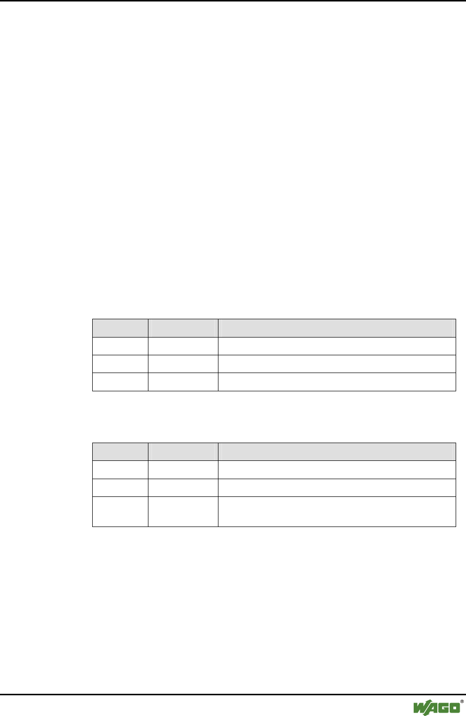
I/O Modules • 55
Special Modules
WAGO-I/O-SYSTEM 750
I/O Modules
2.1.1.8.3.4 Parameter Sets
For use of the parameter channel; parameter sets are defined and indexed us-
ing parameter addresses (A7...A0). Module-specific parameters (parameters 0
through 249) and general system parameters (parameters 250 through 255) are
differentiated.
2.1.1.8.3.5 Process of Parameter Transmission
The parameter data exchange between the application and bus module is made
via request/response process. The application initiates an instruction using the
toggle bit (TGL_MS != TGL_SM). Afterward, the application queries the
communication control register (R57) of the module until the module confirms
the execution of the instruction (TGL_SM == TGL_MS).
The possible instructions to the parameter interface of the bus module are
listed in the following.
2.1.1.8.3.5.1 Calculate the Maximum Parameter Data of the Bus Module (Sys-
tem Parameters)
Query (application)
Parameter Value Description
TGL_MS != TGL_SM Enter instruction
PRM_RW = FALSE Read access
A0…A7 255 Address of parameter data length
Response (bus module)
Parameter Value Description
TGL_SM == TGL_MS Instruction completed
A0…A7 255 Address of parameter data length mirrored
PRM0...
PRM15
N Number of parameter data in address area 0...(n-1),
n ∈ {N < 250}
56 • I/O Modules
Special Modules
WAGO-I/O-SYSTEM 750
I/O Modules
2.1.1.8.3.5.2 Set Factory Settings (System Parameters)
Query (application)
Parameter Value Description
TGL_MS != TGL_SM Enter instruction
PRM_RW = TRUE Write access
A0...A7 255 Address of factory settings
Response (bus module)
Parameter Value Description
TGL_SM == TGL_MS Instruction completed
A0...A7 255 Set address of factory setting, mirrored
By writing 255 on the parameter address, the factory setting of the internal
data bus subsystem for the Bluetooth® module is restored. This includes the
size of the process image and mailbox. The settings of the Bluetooth® subsys-
tem can only be accessed through the mailbox interface and can be separately
reset to standard values via mailbox command (see Appendix 6.3.5.22).
2.1.1.8.3.5.3 Read/Write Parameters (Module-Specific)
Query (application)
Parameter Value Description
TGL_MS != TGL_SM Enter instruction
= FALSE Read access PRM_RW
= TRUE Write access
= FALSE Parameter data transmission is completed. MORE_PRM
= TRUE More parameter data to follow.
A0...A7 0...(n-1) Parameter address
PRM0... PRM15 0 ...65535 Parameter data write access
I/O Modules • 57
Special Modules
WAGO-I/O-SYSTEM 750
I/O Modules
Response (bus module)
Parameter Value Description
TGL_SM == TGL_MS Instruction completed
A0...A7 0...(n-1) Address parameter data mirrored
TIMEOUT FALSE, TRUE Monitoring time expired
BUF_OFL FALSE, TRUE Access outside the module parameter range
PRM_ERR FALSE, TRUE Parameter/parameter set error
PRM0... PRM15 0 ...65535 Parameter data read access
The module uses the error flags TIMEOUT, BUF_OV and PRM_ERR to re-
port errors during the parameter data exchange.
After the last parameter data has been sent to the module (MORE_PRM =
FALSE), the module checks the entire parameter set and accepts it if every-
thing is correct. Otherwise, the module returns a parameter error (PRM_ERR
= TRUE).
2.1.1.8.3.5.4 Example: Configuring Bluetooth® Process Data and Mailbox
Only parameter 0 of the Bluetooth® module can be changed by the user. This
affects the configuration of the size of the process image and mailbox.
Query (application)
Parameter Value Description
TGL_MS != TGL_SM Enter instruction
PRM_RW = TRUE Write access
MORE_PRM = FALSE Parameter data transmission is completed.
A0…A7 0 Parameter address
PRM0...PRM7 DATA_LEN 12, 24 or 48 bytes of data length
PRM8... PRM14 MBX_LEN 6, 12 or 18 bytes of mailbox size
PRM15 MBX_MODE TRUE - Mailbox covers the process data (by set-
ting bit 25 in the control byte)
Response (bus module)
Parameter Value Description
TGL_SM == TGL_MS Instruction completed
A0...A7 0 Address parameter data mirrored
TIMEOUT FALSE, TRUE Monitoring time expired
BUF_OFL FALSE, TRUE Access outside the module parameter range
PRM_ERR FALSE, TRUE Parameter/parameter set error

58 • Configuration of a Bluetooth® Piconet
Special Modules
WAGO-I/O-SYSTEM 750
I/O Modules
3 Configuration of a Bluetooth® Piconet
To configure a piconet, connect 2 to 8 Bluetooth® devices with each other. In
doing so, there is some important framework data to consider:
Is real-time or ad hoc communication beneficial for your application?
Is the data that you wish to transmit time-critical data?
Also important, how many WAGO Bluetooth® modules and how many exter-
nal Bluetooth® modules are to communicate with each other: If only WAGO
devices are to be connected with each other, you can connect one master with
seven slaves. This only applies for the real-time profile, however. In the ad
hoc profile, you can connect up to six WAGO slaves. If you also want to use
external Bluetooth® devices in your piconet, choose the ad hoc profile. In this
profile, seven WAGO devices and six external devices can be linked, but only
a maximum of seven devices can actively exchange data at the same time.
In preparation for configuration, note which Bluetooth® device will take over
which role (master/slave), what the MAC addresses of the devices are and
which communication profile is to be set (real-time/ad hoc). This makes the
overview easier for you.
These considerations will determine the allocation of the devices to available
slots in the master process image. These are available for the data exchange.
In a later step, you will determine the number of bytes (cutoff size) for each
slot that should be available in the master process image for data exchange.
Only the process data allocated to the slots will be transmitted wirelessly.
Therefore, your configuration will work most efficiently if slave devices are
set to the smallest possible process image size. The smallest possible process
image size for a slave corresponds to the smallest setting for its process image
size, which is the same or larger [2 + cutoff of the corresponding slot].
After drafting your configuration in the previous steps, you can now synchro-
nize the device configurations to each other. To do this, first configure the
process image and mailbox size.
The mailbox size determines which mailbox commands can be executed. To
configure with WAGO-I/O-CHECK or building blocks of the WAGO-I/O-
PRO CAA, you can choose each available mailbox size independently of limi-
tations of the fieldbus. For a successful configuration, a mailbox size of at
least 12 bytes is necessary. If you want all diagnostic commands available to
the full extent, set it for 18 bytes. If you are using a fieldbus over which less
than 20 bytes per data element can be transmitted (e.g. CANopen), you should
reduce the mailbox size again to an appropriate size after successfully com-
pleting the device configuration.
If you plan to use the mailbox during ongoing communication; e.g., for diag-
nostic purposes, take note that when unmasking the mailbox, process data may
be temporarily covered (see Section 2.1.1.8.2.1, "Aging of data by the mail-

Configuration of a Bluetooth® Piconet • 59
Special Modules
WAGO-I/O-SYSTEM 750
I/O Modules
box"). In this case, you can also configure in such a way that the first slot has
no device allocated to it and the size of the first slot corresponds to the mail-
box size. This does mean, however, that one less device can be linked, but the
up-to-dateness of the process data is not dependent on the masking or unmask-
ing of the mailbox. But this is only possible for the module configured as the
master since slave process images always consist of only one individual slot
(in the master) and these do not begin until the third byte.
After configuring the process image and mailbox size, you can continue with
the device configuration. Please make sure that the module is in configuration
mode for the remainder of the steps.
Assign each device its intended role (master or slave). For each slave, enter
the master in the first slot in the list of allowed WAGO devices. For the mas-
ter, all intended slaves are assigned slots in the list of allowed WAGO or ex-
ternal devices. For each slot, set the planned data width (cutoff).
For master/slave communication over Bluetooth®, make sure that the settings
for encryption, authentication and PIN are identical in the devices. For maxi-
mum security, it is recommended that you keep the factory setting for "En-
cryption" at "On" and "Authentication" at "Password". The preset password,
“0000” should be changed to a project-specific password.
At the end of the device configuration process, you will change to communi-
cation mode - in the ad hoc or real-time profile, depending on the type of
slaves. With correct configuration, devices within range should automatically
establish a connection to each other. The establishment of a connection is es-
pecially fast if you first startup the slaves and then the master.
As soon as the connections are established, master and slaves exchange data
with each other, depending on the slot configuration. You can continue to set
mailbox commands in communication mode as well. An example being to
change the operating mode again or to query diagnostic information.
Section 4 below describes the Bluetooth®-specific configuration interface
WAGO-I/O-CHECK and the process of configuring a Bluetooth® module 750-
644. In Appendix 6.5, concrete example configurations are also provided.
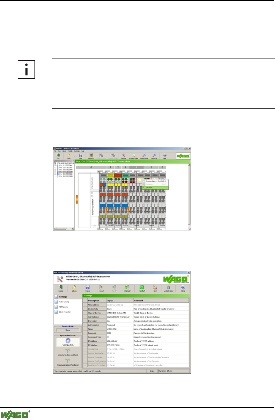
60 • Tools for Configuring and Operating
Special Modules
WAGO-I/O-SYSTEM 750
I/O Modules
4 Tools for Configuring and Operating
The Bluetooth® module is configured using the WAGO-I/O-CHECK software
(Version 3 or later). The software's basic functionality is described separately
in the WAGO-I/O-CHECK documentation.
Additional Information
You can obtain the WAGO-I/O-CHECK software (Version 3 or later) on CD
ROM using order number 750-302. The CD ROM contains all programming
files for the application. The documentation for the WAGO-I/O-CHECK soft-
ware can be obtained online at http://www.wago.com under Documentation !
WAGO Software 759 ! WAGO-I/O-CHECK.
The specific parameterization dialog for the Bluetooth® module is opened by
right clicking on a Bluetooth® module and selecting the menu item Settings
(see Figure 18).
Figure 18: User interface of WAGO-I/O-CHECK g064417e
The content of the parameterization dialog (see Figure 19) forms the basis of
the following description.
Figure 19: Bluetooth® parameterization dialog g064418e
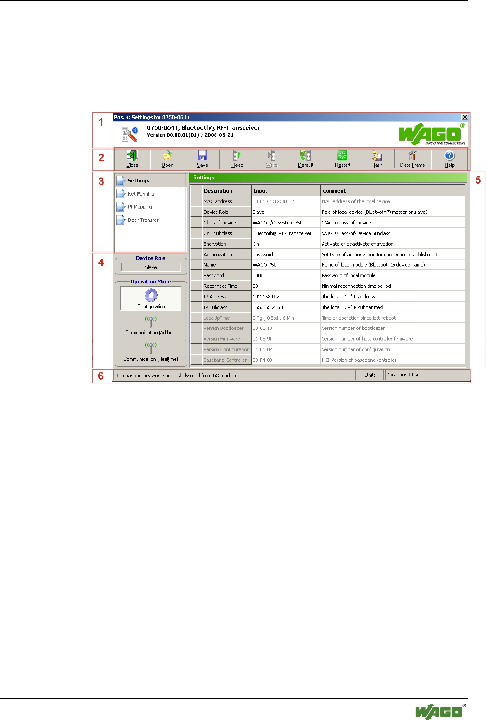
Tools for Configuring and Operating • 61
Configuring and Operating with WAGO-I/O-CHECK
WAGO-I/O-SYSTEM 750
I/O Modules
4.1 Configuring and Operating with WAGO-I/O-CHECK
4.1.1 User Interface
The user interface of the Bluetooth® parameterization dialog is divided into the
following areas (see Figure 20):
Figure 20: User interface of the Bluetooth® parameterization dialog g064419e
1. Title bar (see Section 4.1.1.1)
2. Symbol bar (see Section 4.1.1.2)
3. Navigation (see Section 4.1.1.3)
4. Mode assignment (see Section 4.1.1.4)
5. Parameterization area (see Section 4.1.1.5)
6. Status display (see Section 4.1.1.6)
The areas are explained in more detail in the following Sections.
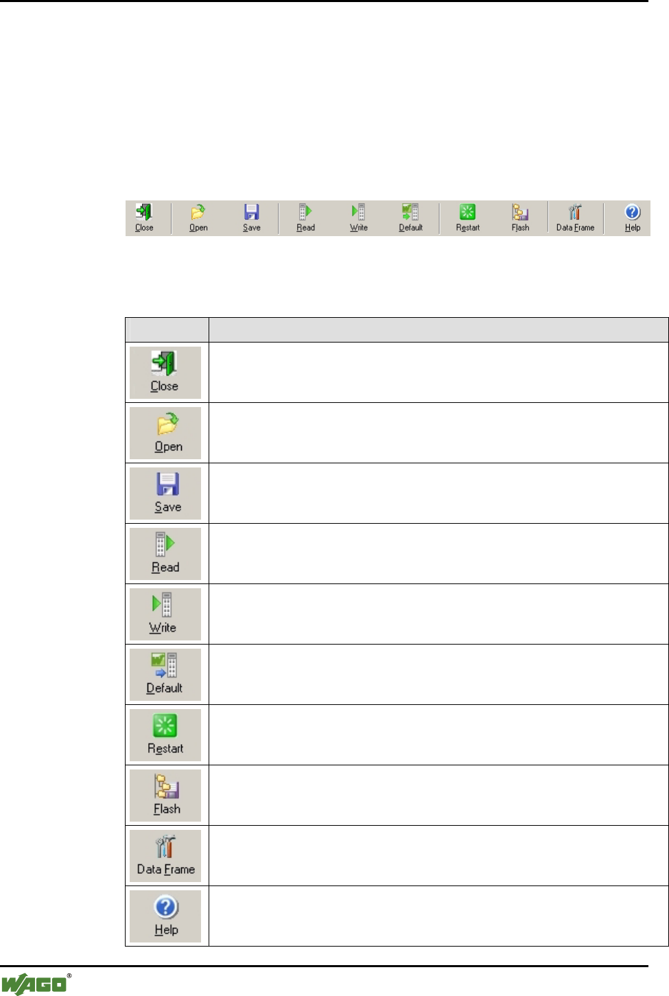
62 • Tools for Configuring and Operating
Configuring and Operating with WAGO-I/O-CHECK
WAGO-I/O-SYSTEM 750
I/O Modules
4.1.1.1 Title Bar
The position of the module within the node (as well as its name and item and
version number) are displayed in the title bar of the parameterization dialog.
4.1.1.2 Symbol Bar
The symbol bar in the Bluetooth® parameterization dialog contains the follow-
ing buttons (see Figure 21):
Figure 21: Buttons in the Bluetooth® parameterization dialog g064420e
Table 24: Buttons in the Bluetooth® parameterization dialog g064421e-30e
Button Description
[Close]
Closes the active window. If you have changed settings, you will be asked to
accept the values in the I/O module.
[Open]
Opens window to select a parameter file. Device settings are read from the pa-
rameter file and transferred to the connected I/O module.
[Save]
Opens a window to select a parameter file. The device settings are saved in the
parameter file.
[Read]
Reads the current settings from the connected I/O module and displays them in
this window.
[Write]
Transfers the settings displayed in this window to the connected I/O module.
[Default]
Overwrites the locally saved configuration with the factory settings.
[Restart]
Restarts the host controller.
Attention: All wireless connections are broken off.
[Flash]
Writes the current configuration of the host controller to the flash memory and
restarts it. Attention: All wireless connections are broken off.
[Data Frame]
Sets process size and mailbox size.
[Help]
Displays help for this window.
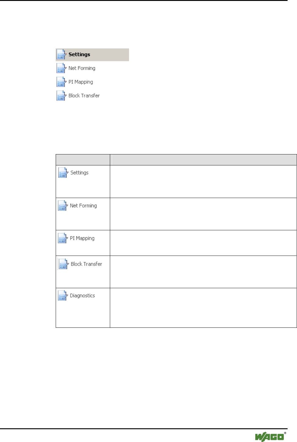
Tools for Configuring and Operating • 63
Configuring and Operating with WAGO-I/O-CHECK
WAGO-I/O-SYSTEM 750
I/O Modules
4.1.1.3 Navigation
You can toggel between the different configuration areas of the module by us-
ing the navigation on the left side of the screen (see Figure 22).
Figure 22: Navigation between configuration areas g064431e
Choose between the following menu items (see Table 25):
Table 25: Navigation between configuration areas g064432e-36e
Menu item Description
[Settings]
Opens a page with general module parameters such as device name, MAC
address, device role, etc. These parameters can be altered here and loaded
to the module (see Section 4.1.1.5.1, "Settings").
[Net Forming]
Opens a page with device lists. Here, configured and bound devices
within range are displayed with MAC address and name and configured
(see Section 4.1.1.5.2, "Net Forming").
[PI Mapping]
Opens a page for the allocation of slave process data to slots in the master
(see Section 4.1.1.5.3, "PI Mapping").
[Block Transfer]
Opens a page for viewing the process data during uploading and
downloading. The menu entry "Block transfer" is only displayed in the
configuration mode (see Section 4.1.1.5.4, "Block Transfer").
[Diagnostics]
Opens a page with comprehensive diagnostic information on the status of
the module and the network as well as the connection quality (see Section
4.1.1.5.5, "Diagnostics"). The menu entry "Diagnostics" is only displayed
in the communication mode.
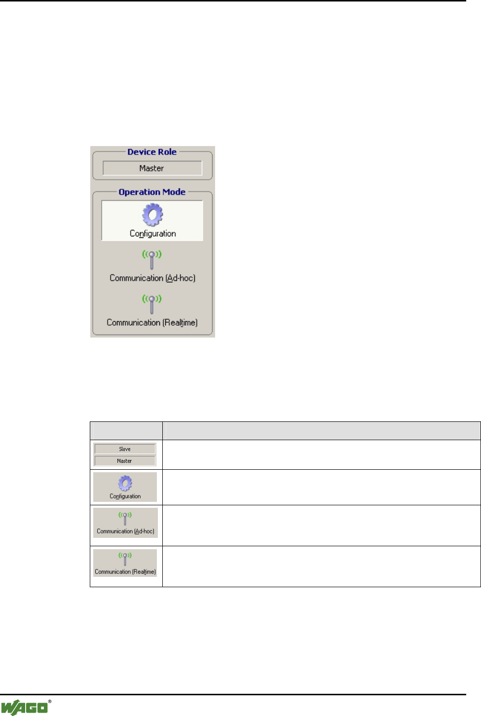
64 • Tools for Configuring and Operating
Configuring and Operating with WAGO-I/O-CHECK
WAGO-I/O-SYSTEM 750
I/O Modules
4.1.1.4 Mode Assignment
Device Role is displayed in the top area, indicating whether the currently con-
figured module is a master or a slave.
The lower area, Operation Mode is used to assign the mode to the locally
connected module. Using the buttons, choose whether the module is to be op-
erated in either the configuration or communication mode (real-time or ad hoc
profile) (see Figure 23).
Figure 23: Changing mode g064437e
Choose between the following menu items:
Table 26: Navigation between configuration pages g064438e-42e
Menu item Description
"Slave" or "Master"
Displays the currently assigned device role of the local module.
[Configuration]
Switches the locally connected module to the configuration mode.
[Communication (Ad-hoc)]
Switches the locally connected module to the communication mode
(ad hoc profile).
[Communication (Realtime)]
Switches the locally connected module to the communication mode (real-time
profile).
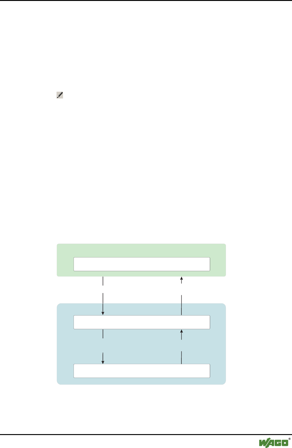
Tools for Configuring and Operating • 65
Configuring and Operating with WAGO-I/O-CHECK
WAGO-I/O-SYSTEM 750
I/O Modules
4.1.1.5 Parameterization Area
In the parameterization area, the Bluetooth® module is configured and pre-
pared for communication. This is described in further detail in the following
sections.
Changing and saving data
To change settings in the Bluetooth® module, adjust the values displayed in
the parameterization area. Altered settings are labeled with a change symbol
. This indicates that the displayed values are no longer the same as the origi-
nally queried values of the module. To transfer the new values to the module,
click on the [Write] button. The change symbols will disappear.
In this writing process, the values of the module are first temporarily saved so
that clicking on [Restart] can delete the changes again. In this case, you
should update the graphic display of the values after restart by clicking on
[Read].
To save transferred value changes permanently (flash process) without chang-
ing the operating mode, click on [Flash]. You may also change the module to
another operating mode. When you do this, transferred changes are automati-
cally and permanently saved. For example, you can change the module over to
the communication operating mode (real-time) after completing configuration
under Net Forming. This will cause the altered configuration to be saved, and
the module attempts immediately to exchange data with the configured partner
devices.
WAGO-I/O-CHECK
Bluetooth
®
Preview for module's settings
Memory of module's settings (non-volatile)
Buffer for new settings (volatile)
WAGO Module
[Save] [Read] or open
the dialog window
[Flash] or change of operation mode
(when the configuration is completed)
Module's start-up
or restart
Figure 24: Saving the configuration g064471e
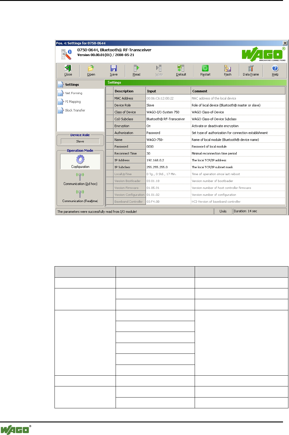
66 • Tools for Configuring and Operating
Configuring and Operating with WAGO-I/O-CHECK
WAGO-I/O-SYSTEM 750
I/O Modules
4.1.1.5.1 Settings
Settings displays general module parameters (see Figure 25).
Figure 25: Settings g064418e
The following parameters can be changed and loaded to the module.
Table 27: Navigation between configuration pages
Name Entry/Selection Description
MAC Address _ _ : _ _ : _ _ : _ _ : _ _ : _ _ MAC address of the device
Master Assignment of the master role Device Role
Slave Assignment of the slave role
WAGO Speedway 767
WAGO System 763
WAGO-I/O-SYSTEM 757
WAGO-I/O-SYSTEM 755
WAGO-I/O-SYSTEM 753
Class of Device
WAGO-I/O-SYSTEM 750
WAGO Class-of-Device
(for Bluetooth®, "WAGO-I/O-
System 750" is set)
CoD Subclass Bluetooth® RF Transceiver WAGO CoD subclass
On Switch on encryption Encryption
OFF Switch off encryption

Tools for Configuring and Operating • 67
Configuring and Operating with WAGO-I/O-CHECK
WAGO-I/O-SYSTEM 750
I/O Modules
Name Entry/Selection Description
OFF No authorization required.
Password For external devices, password entry
is required. The "Link key" for the
authorization must be recalculated
for each established connection.
Authorization
Link key The "Link key" for the authorization
does not have to be recalculated.
After a first-time connection, enter-
ing the password is no longer neces-
sary for an external device either.
Name Entry as ASCII characters,
length dependent on mailbox
size (max. 16 characters)
Name of the local module (Blue-
tooth® Device Name)
Password Entry as ASCII characters,
length dependent on mailbox
size
Password of the local module
Reconnect Time _ Smallest time interval in seconds
between two attempts to connect
IP Address _ _ _ ._ _ _ ._ _ _ ._ _ _ The local TCP/IP address
IP Subclass _ _ _ ._ _ _ ._ _ _ ._ _ _ The local TCP/IP subnet mask
LocalUpTime _ _ days, _ _ hours., _ _ min. Operating time of the module since
the last restart
Version of boot loader _ _ . _ _ ._ _ Version number of the boot loader
Firmware version _ _ . _ _ ._ _ Version number of the firmware
Version of configura-
tion
_ _ . _ _ ._ _ Configuration version number
Baseband controller _ _ . _ _ ._ _ HCI version of the baseband con-
troller
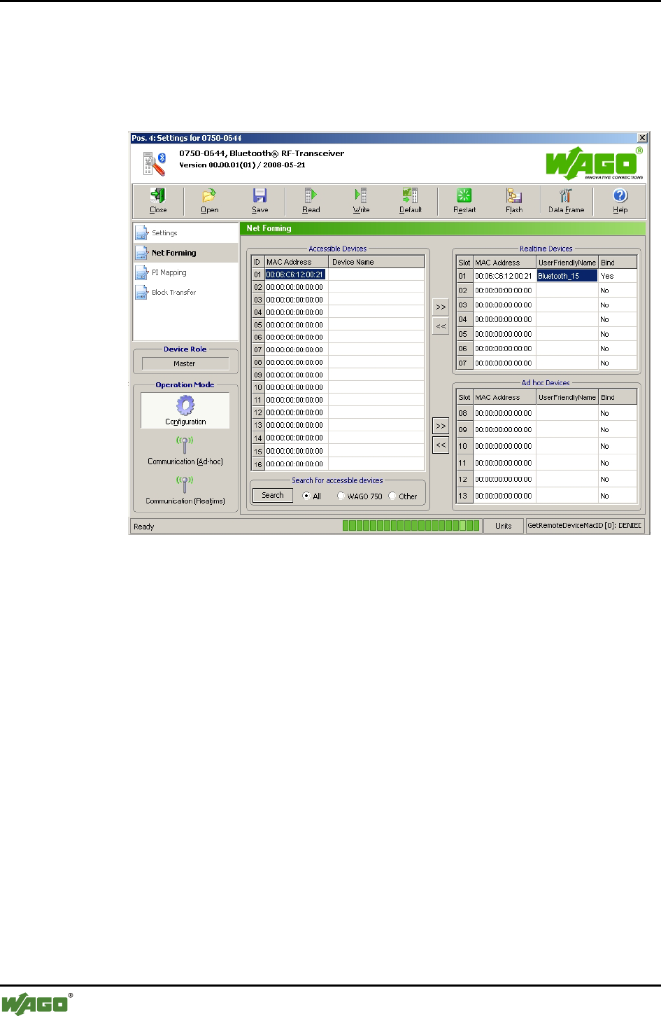
68 • Tools for Configuring and Operating
Configuring and Operating with WAGO-I/O-CHECK
WAGO-I/O-SYSTEM 750
I/O Modules
4.1.1.5.2 Net Forming
"Net Forming" refers to the configuration of the Bluetooth® network. On the
"net forming" side, devices are manually entered or automatically sought and
bound for later communication.
Figure 26: Net forming g064443e
On the left side, all devices within range are displayed. You update the list by
clicking on the [Search] button.
Depending on the option selected, you can limit the search for devices. The
Class-of-Device (CoD) is used as a criterion for filtering search results.
Select All to search for any Bluetooth® devices within range in the environ-
ment.
Select WAGO 750 to search for all WAGO devices of the model series 750
within range.
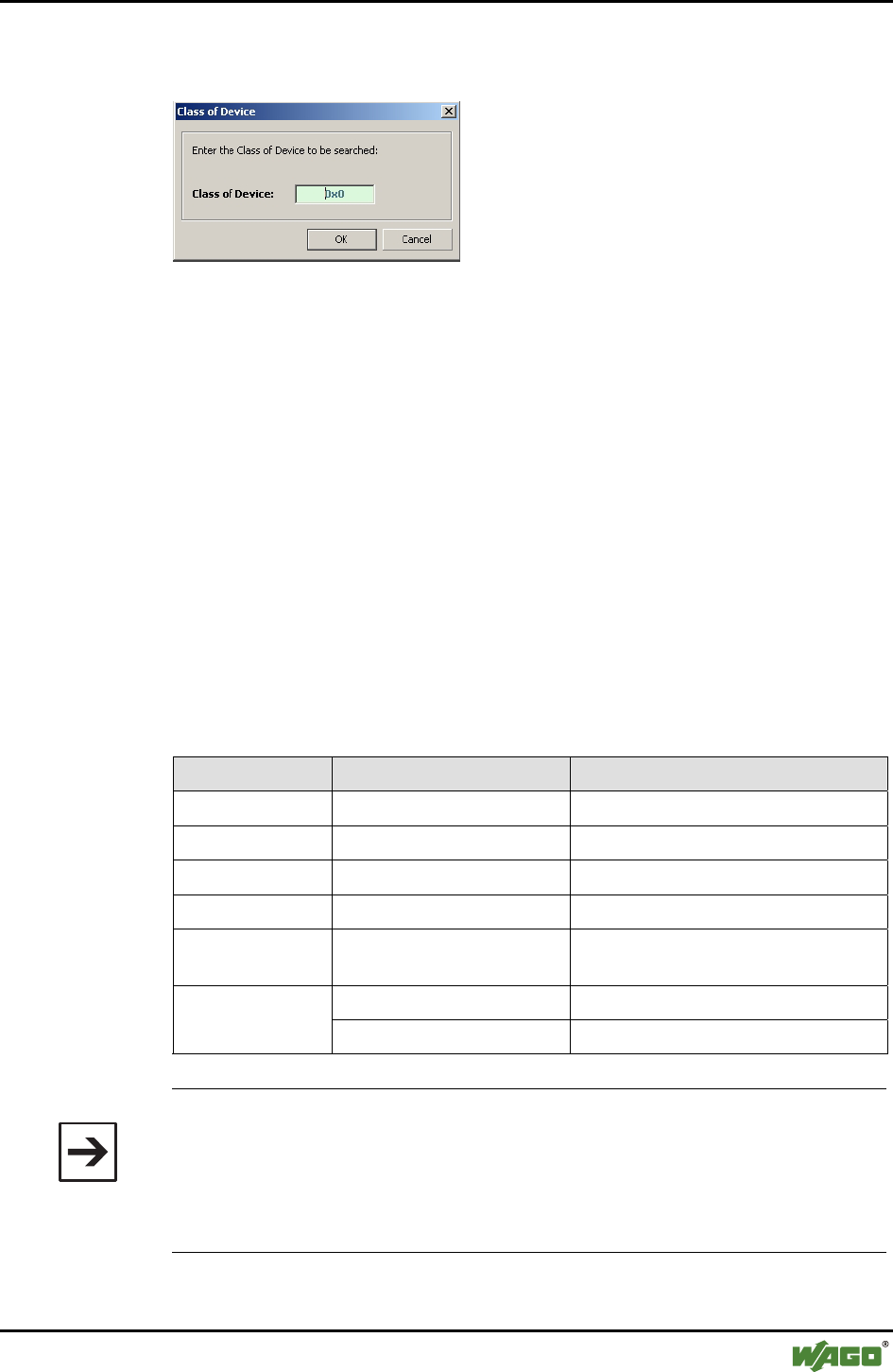
Tools for Configuring and Operating • 69
Configuring and Operating with WAGO-I/O-CHECK
WAGO-I/O-SYSTEM 750
I/O Modules
Select Other to manually enter which CoD should be used to filter the search
results (see Figure 27).
Figure 27: Filter according to device classes g064489e
To the right on the "net forming" page, the configured devices are displayed in
two lists. The upper list contains WAGO devices using the real-time profile.
The lower list contains both WAGO and/or external devices using the ad hoc
profile.
Selected devices within range are added to the real-time or ad hoc list by using
the [>>] button. MAC addresses or device names can also be moved to the ad
hoc or real-time list by drag & drop from the list of devices within range.
Selected devices are deleted from the real-time or ad hoc list using the [<<]
button. Deleting the device is also possible by double-clicking on the respec-
tive MAC address.
The tables on the Net forming page are filled as follows:
Table 28: Table identifiers in "Net forming"
Name Entry/Selection Description
IS _ _ Device ID for devices within range
MAC Address _ _ : _ _ : _ _ : _ _ : _ _ : _ _ MAC address of the device
Device name ASCII characters Device name (cannot be changed)
Slot _ Slot number of allocated device
UserFriendlyName ASCII characters Name assigned to a slot (can be
changed)
Yes Bind device ("Yes") Bind
No Do not bind device ("No")
Note
Remember when assigning a "UserFriendlyName", you must display the en-
tire length of the name; a mailbox size of 18 bytes is necessary. With a
smaller mailbox setting, the full name is actually displayed within WAGO-
I/O-CHECK, but not completely saved, so when the name is read back from
the module, not all the characters are displayed.
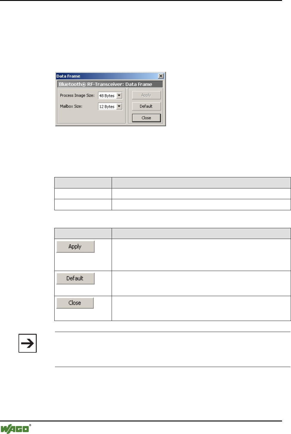
70 • Tools for Configuring and Operating
Configuring and Operating with WAGO-I/O-CHECK
WAGO-I/O-SYSTEM 750
I/O Modules
4.1.1.5.3 PI Mapping
To undertake settings on the "PI mapping" (process image mapping) page, the
process image size of the master must first be set.
Use the [Data Frame] button in the symbol bar to open the dialog for entering
the process image and mailbox sizes (see Figure 28).
Figure 28: Determine data framework g064444e
The following settings are possible (see Table 29):
Table 29: Determine data framework
Toggle field Settings
Process image size 12 bytes, 24 bytes, 48 bytes*
Mailbox size 6 bytes, 12 bytes, 18 bytes*
* Standard setting
Button Description
[Apply]
Transfers the altered parameters to the module's permanent memory. A
software reset is conducted so that the changes take effect. The dialog
remains open.
[Default]
Selects the standard setting for this module. Then transfer the parameters
to the permanent memory of the module by using the [Apply] button.
[Close]
Ends the parameterization dialog without transferring any altered pa-
rameters to the permanent memory of the module.
Note
Please note that the structure of the process image changes when the process im-
age size or mailbox size is changed. Therefore, changes in the configuration of
the superordinate control may be necessary.
On the "PI mapping" page, the slave process data is allocated to the slots in
the master (see Figure 29). Up to 46 bytes of the process image are available
for this purpose (depending on which process image size was set in the "Data
framework" dialog). The control/status byte and internal byte are not taken
into consideration here.
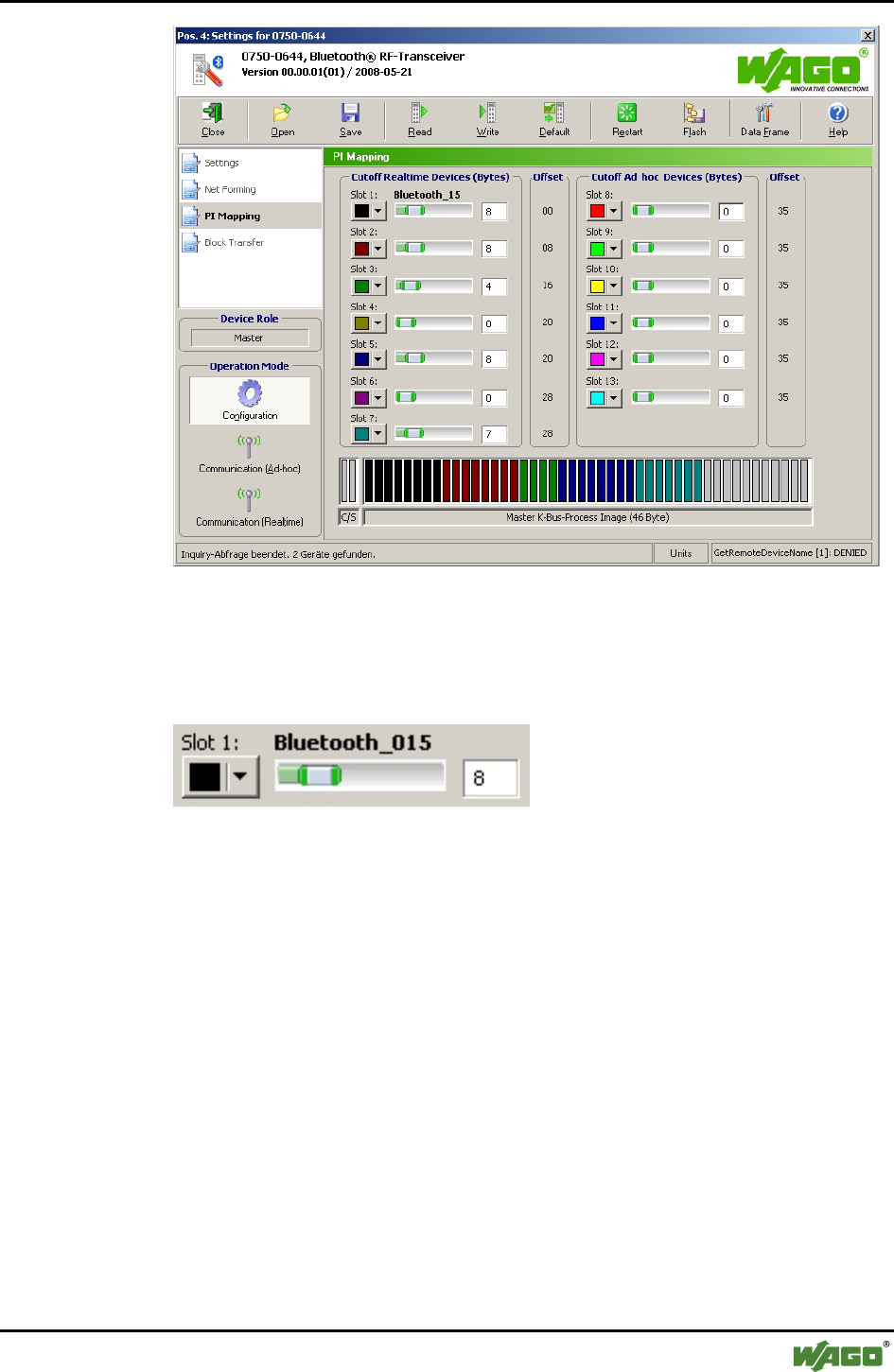
Tools for Configuring and Operating • 71
Configuring and Operating with WAGO-I/O-CHECK
WAGO-I/O-SYSTEM 750
I/O Modules
Figure 29: PI mapping g064445e
On the left side, slots 1 through 7 for the real-time profile are displayed (for
WAGO devices only). The right side displays slots 8 through 13 for the ad hoc
profile (for WAGO and external devices). Each line labels a slot ( Figure 30):
Figure 30: Display of a slot g064446x
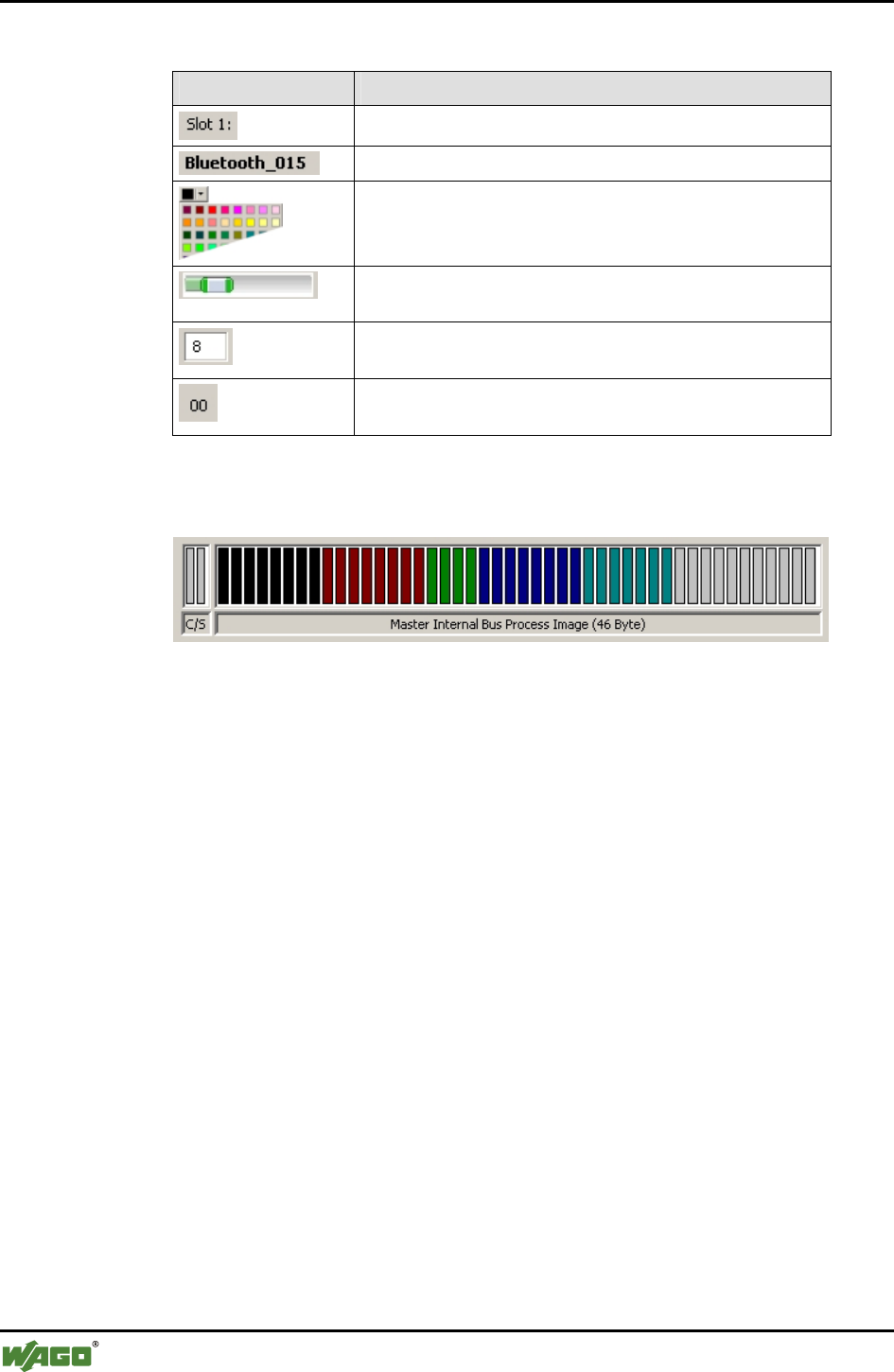
72 • Tools for Configuring and Operating
Configuring and Operating with WAGO-I/O-CHECK
WAGO-I/O-SYSTEM 750
I/O Modules
Table 30: Display of a slot g064447x-51x
Setting Description
Identification of slots (1…7 real-time, 8…13 ad hoc)
Display of the "UserFriendlyName", if provided
Selection of slot color for the graphic display in the lower
area (see Figure 29)
Sliding controller for the size of the process data in bytes
(cutoff size) assigned to a slot
Entry field for the size of the process data in bytes (cutoff
size) assigned to a slot
Offset in bytes at the beginning of the slot
(without control/status and internal bytes)
The master process image with the distribution of the slots is graphically dis-
played below the slot configuration (see Figure 31).
Figure 31: Slot allocation g064452e
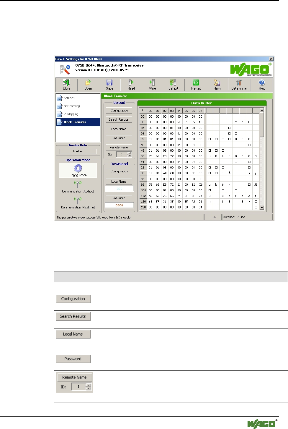
Tools for Configuring and Operating • 73
Configuring and Operating with WAGO-I/O-CHECK
WAGO-I/O-SYSTEM 750
I/O Modules
4.1.1.5.4 Block Transfer
This page displays the configuration block during uploading and downloading
of the process data (see Figure 32). The menu item Block Transfer is only
visible in the configuration mode.
Figure 32: Block transfer g064453e
Choose between the following menu items:
Table 31: Block transfer g064454e-58e
Menu item Description
Upload
v [Configuration]
Displays the configuration transferred from the module to the application.
[Search Results]
Displays the list of MAC addresses found during a search.
[Local Name]
Displays the complete local name of the module (in menu item "Settings", the
name may be incomplete due to insufficient mailbox size).
[Password]
Loads the set password.
[Remote Name]
Displays the device names of the connected modules. By entering an ID (see
page on Net forming), the device name of a special Bluetooth® device is
displayed.
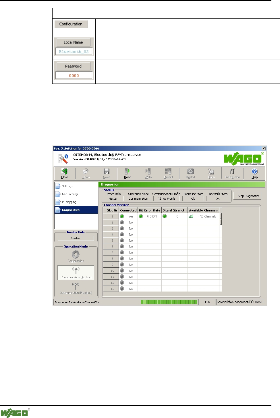
74 • Tools for Configuring and Operating
Configuring and Operating with WAGO-I/O-CHECK
WAGO-I/O-SYSTEM 750
I/O Modules
Download
[Configuration]
Writes the configuration to the module.
[Local Name]
Writes the local name to the module. The name can be entered in the entry
field.
[Password]
Writes the password in the locally connected module. The password can be
entered in the entry field.
4.1.1.5.5 Diagnostics
This page displays diagnostic information on the module status, the network
and the quality of the connection (see Figure 33). The menu item
Diagnostics is only visible in the communication mode.
Figure 33: Diagnostics g064459e
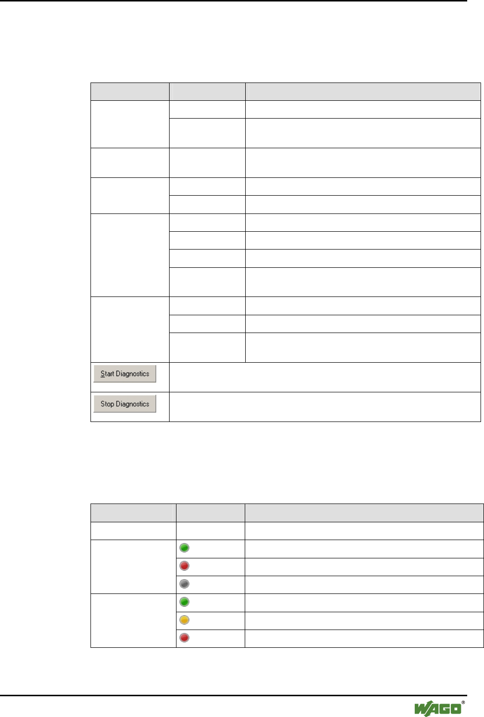
Tools for Configuring and Operating • 75
Configuring and Operating with WAGO-I/O-CHECK
WAGO-I/O-SYSTEM 750
I/O Modules
The following displays are summarized under the header "Status"
(see Table 32):
Table 32: General status display
Status Value Description
Slave Device takes over the role of "slave" Device Role
Master Device takes over the role of "master"
(see also Appendix 6.3.5.20, "GetLocalDeviceRole")
Operating Mode Communication Device is in communication mode
(see also Appendix 6.3.3.2, "GetLocalOperationMode")
Real-time profile Device is in the communication profile "real-time" Communication
Profile Ad hoc profile Device is in the communication profile "ad hoc"
Ok No warnings/errors
Warning Warning
Error General error
Diagnostic State
Critical defect Critical error (for details see Appendix 6.3.6.1, "GetLo-
calDeviceStatus")
Ok Configured network is established.
Inconsistent Not all configured connections are established.
Network Status
Defective Configured network is (still) not established.
(for details see Appendix 6.3.6.2, GetNetworkStatus)
[Start Diagnostics]
Start value monitoring
[Stop Diagnostics]
End value monitoring
Under "Channel monitor", the transmission quality for each slot is displayed
(see Table 33):
Table 33: Status of transmission channel
Status Value Description
Slot No. Slot _ Slot Number
Yes Connected
No Not connected
Connected
No No device configured for this slot
0 % No bit error occurred
0.1…10% Some bit errors occurred
Bit Error Rate
> 10% High bit error rate
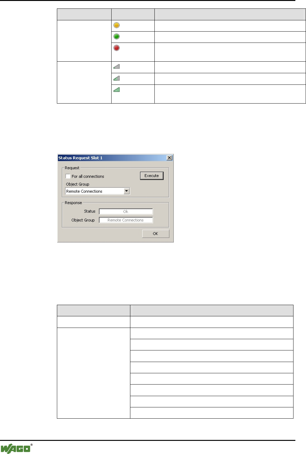
76 • Tools for Configuring and Operating
Configuring and Operating with WAGO-I/O-CHECK
WAGO-I/O-SYSTEM 750
I/O Modules
Status Value Description
-127...0 RSSI value/signal strength too weak
0 Signal strength very good
Signal Strength
0...+127 Signal strength too strong
(see Appendix 6.3.6.5, "GetLinkSignalStrength")
< 39 Too many busy/defective channels
39…53 Some busy/defective channels
Available Channels
> 53 Free/undisturbed channels (low interference)
(see Appendix 6.3.6.6, "GetAvailableChannelMap")
Click on one of the fields of the last column of the table. A dialog with a de-
tailed status display for the selected slot opens (see Figure 34). Choose For all
connections by checking it to query the status of all slots.
Figure 34: Status query for slots g064475e
By selecting a certain Object group, you are limiting the status reports ac-
cordingly (see Table 34).
Table 34: Object groups and possible status reports
Object Groups Status *
Whole system Ok
Ok
Not specified
BER is moderate
BER is high
Less than 39 channels available
Less than 54 channels available
Connection error
Wireless connections
Connection interrupted
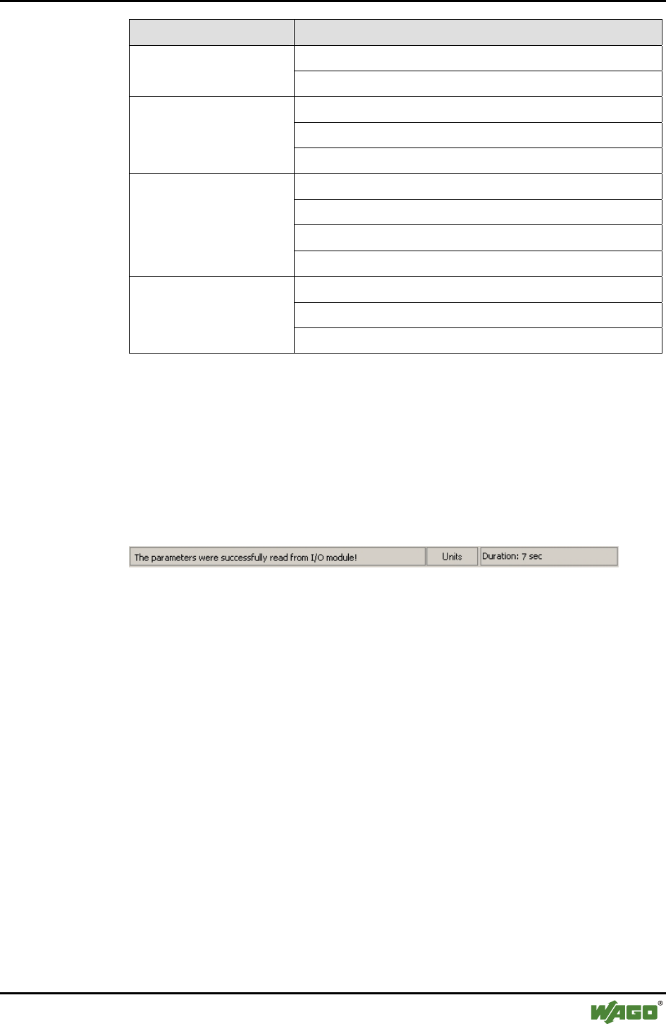
Tools for Configuring and Operating • 77
Configuring and Operating with WAGO-I/O-CHECK
WAGO-I/O-SYSTEM 750
I/O Modules
Object Groups Status *
Ok Time monitoring
Watchdog
Ok
Process image is defective
Process image
A remote mailbox is active
Ok
Interruption in SPI communication
SPI is overloaded
Intersystem communica-
tion
Error in the mailbox communication
Ok
Configuration altered
Configuration
Error in the network configuration
* The meaning of the individual status reports can be found in Appendix 6.3.6.3.
You can query the status with the set parameter by using the [Execute] button.
4.1.1.6 Status Display
Status reports are given in the status display in the lower area of the parame-
terization dialog. The display varies depending on the page accessed:
Settings, Net forming, PI Mapping, Block Transfer and Diagnostics.
Figure 35: Status display g064460e

78 • Tools for Configuring and Operating
Configuring the Bluetooth® Module 750-644
WAGO-I/O-SYSTEM 750
I/O Modules
4.2 Configuring the Bluetooth® Module 750-644
In order to work with the Bluetooth® module 750-644, you must first set up the
communication connection to your node. Then read the node configuration
and select the desired module in the navigation or node view.
Next, set the necessary process data and mailbox size in the parameterization
dialog. After that, you can set the desired operating mode for the master in the
process data dialog or select a slave for further processing from the list of
slave addresses.
Use the diagnostic function to eliminate configuration errors.
4.2.1 Setting the Bluetooth® Process Data and Mailbox Size
If the parameterization dialog is not open, select Settings in the context menu
of the selected module (node view or navigation).
Using the [Data Frame] button in the symbol bar, open a dialog in which you
establish the size of the process image in the internal data bus 12, 24 or 48
bytes. Choose 6, 12 or 18 bytes as the mailbox size.
Note
The available combinations of possible selections correspond to the configu-
rations projectable by PROFIBUS or CANopen type files.
To display the standard values for the module, press the [Default] button. The
displayed values can then be changed.
Transfer the set values to the permanent memory of the module by pressing
the [Apply] button; exit the dialog by pressing [Close].
4.2.2 Setting the Mode
If the parameterization dialog is not open, select Settings in the context menu
of the selected module (node view or navigation).
The area Device Role displays whether the module is configured as master or
slave. Under that, in the Operating mode area are three buttons: [Configura-
tion], [Communication (Ad-hoc)] and [Communication (Realtime)]. Press
one of these buttons to transfer the module to the respective mode or respec-
tive profile. No explicit writing to the module is necessary.

Tools for Configuring and Operating • 79
Configuring the Bluetooth® Module 750-644
WAGO-I/O-SYSTEM 750
I/O Modules
4.2.3 Role Assignment (Master/Slave)
The Bluetooth® module can be configured as either master or slave. Choose
Settings in the context menu of the selected module (node view or navigation)
to open the parameterization dialog. In the navigation to the left, choose Set-
tings. Click in the field to the right beside Device Role. In the dropdown
menu, select "master" to configure the module as a master or "slave" to trans-
fer the role of slave to the module.
Click on the [Write] button in the toolbar to assign the new role to the mod-
ule.
4.2.4 Search for and Display Devices within Range
Choose Settings in the context menu of the selected module (node view or
navigation) to open the parameterization dialog. Choose Net Forming in the
navigation bar. Choose the option All in the area Search for devices within
range and click on the [Search] button. The network is searched for Blue-
tooth® devices within range. Found devices are displayed in the list of devices
within range.
4.2.5 Bind new Devices
Choose Settings in the context menu of the selected module (node view or
navigation) to open the parameterization dialog. Choose Net Forming in the
navigation bar.
Enter Bluetooth® devices either manually, even if they are not (yet) present in
the network, or by using the automatic network search.
4.2.5.1 Entering Bluetooth® Devices manually
In the area real-time devices or ad hoc devices, mark a non-occupied MAC
address and enter the MAC address of the Bluetooth® device with which
communication is to occur. The device does not have to be in the network.
Thus, a network can first be logically constructed and the individual compo-
nents started up later.
Click beside the MAC address in the Bind field and select "Yes" if you would
like to bind the device for communication.

80 • Tools for Configuring and Operating
Configuring the Bluetooth® Module 750-644
WAGO-I/O-SYSTEM 750
I/O Modules
4.2.5.2 Bind Bluetooth® Devices from Network Search
Devices found by using the [Search] button are displayed in the list of devices
within range. These devices can be chosen and transferred to one of the two
lists using the [>>] button on the right side. In doing so, only WAGO devices
are added to the upper list (real-time), while the lower list can take both
WAGO devices and external devices (ad hoc).
Click beside the MAC address in the Bind field and select "Yes" if you would
like to bind the added device for communication. A total of 7 devices (6 de-
vices in the ad hoc profile) can exchange data with a master at the same time.
Therefore, bind a maximum of 7 devices using "Bind", even if you have filled
all thirteen slots with devices.

Tools for Configuring and Operating • 81
Configuring the Bluetooth® Module 750-644
WAGO-I/O-SYSTEM 750
I/O Modules
4.2.6 Assigning Slave Process Data to Slots in the Master
Choose Settings in the context menu of the selected module (node view or
navigation) to open the parameterization dialog. Click on PI Mapping in the
navigation area.
The master only considers parts of the individual slave process images. Select
the size of these parts (cutoff) using the slide control. As an alternative, you
can enter the number of bytes in the entry field to the side.
Please note: Only up to 7 real-time devices or up to 6 ad hoc devices can be
active at the same time. These are the only devices you can bind by selecting
Bind - "Yes" in the PI Mapping configuration area for communication. If you
bind all 13 devices and each of the 13 slots is occupied, only the first six real-
time devices and the first ad hoc device will be free for communication.
4.2.7 Diagnostics
Choose Settings in the context menu of the selected module (node view or
navigation) to open the parameterization dialog. Click on Diagnostics in the
navigation area.
On this page, you will see status reports for the Bluetooth® device, the trans-
mission channel and network displayed. Click on the [Start Diagnostics] but-
ton to constantly query current values. Click on [Stop Diagnostics] to display
the most recently received status with no further updating.
A click on the right column of the table opens a dialog window in which you
can query status information for individual slots or all existing connections by
selecting an object group and clicking [Execute].
Additional Information
An example configuration using WAGO-I/O-CHECK can be found in Ap-
pendix 6.5.
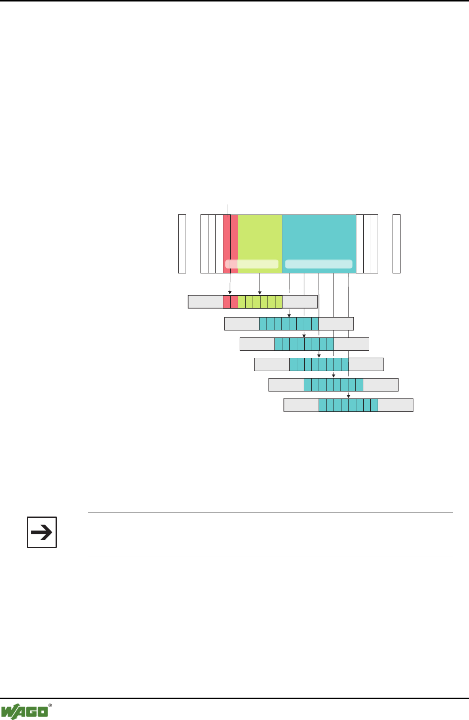
82 • Fieldbus-specific Additions
CANopen
WAGO-I/O-SYSTEM 750
I/O Modules
5 Fieldbus-specific Additions
5.1 CANopen
5.1.1 Process Image Access
The CANopen master accesses the Bluetooth® mailbox and process data in the
coupler/controller using process data objects (PDOs).
In the standard configuration, the Bluetooth® module data is mapped in serial
PDOs. Each PDO can take up eight bytes of data. The maximum Bluetooth®
module process image of 48 bytes therefore includes six PDOs.
……
0 1 2...7* 8...47*
40 47
0
7
7
16 23
815
24 31
32 39
process image
Bluetooth module
PDO for cyclical data
PDO for cyclical data
PDO for cyclical data
PDO for cyclical data
PDO for cyclical data
PDO for status-/control-
byte and mailbox or
cyclical data
Process data
Mailbox
data
zyclicalazyclical
control-/statusbyte
internal byte
* Example with 48 bytes process data, mailbox data 6 bytes (max. for CANopen)
Figure 36: PDO allocation of a Bluetooth® module g064468e
The first PDO allocated to a Bluetooth® module contains the control/status
byte, an empty byte and up to six bytes of mailbox or process data. The fol-
lowing PDOs contain Bluetooth® process data.
Note
If using a CANopen coupler/controller, the maximum mailbox size is lim-
ited to six bytes.
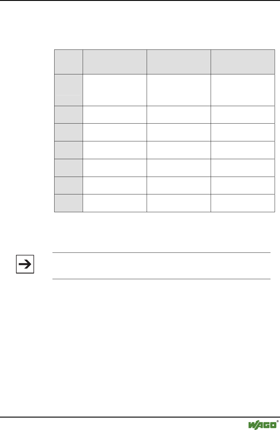
Fieldbus-specific Additions • 83
CANopen
WAGO-I/O-SYSTEM 750
I/O Modules
With a masked or unmasked mailbox, the following allocation of the process
image size to the number of busy PDOs applies.
Table 35: Allocation of the process image size to the number of busy PDOs
Process
image
size
12 bytes 24 bytes 48 bytes
no. PDO
1 control/status byte
1 empty byte
6 bytes of mailbox or
6 bytes of process data
1 control/status byte
1 empty byte
6 bytes of mailbox or
6 bytes of process data
1 control/status byte
1 empty byte
6 bytes of mailbox or
6 bytes of process data
n+1st
PDO
4 bytes process data
4 bytes empty (reserved) 8 bytes of process data 8 bytes of process data
n+2nd
PDO free for next module 8 bytes of process data 8 bytes of process data
n+3rd
PDO - free for next module 8 bytes of process data
n+4th
PDO - - 2 bytes of process data
n+5th
PDO - - 8 bytes empty (reserved)
n+6th
PDO - - free for next module
The 1st PDO contains a control/status byte, an empty byte and six bytes of
mailbox data with an unmasked mailbox or the first six bytes of the process
data. The following PDOs contain the remaining process data.
Note
If the mailbox is unmasked, the first six bytes of process data cannot be
accessed.
If the process image size of the Bluetooth® module is 12, the last PDO is not
completely occupied. Another module then begins with the next PDO.
5.1.1.1 Example
A node contains the following modules with input/output process image:
3 x 750-402 for every 4 bits of input data,
1 x 750-452 4 bytes of input data,
1 x 750-644 12 bytes of input and 12 bytes of output data,
1 x 750-550 4 bytes of output data,
1 x 750-452 4 bytes of input data,
1 x 750-550 4 bytes of output data,
1 x 750-452 4 bytes of input data,
1 x 750-504 4 bits of output data.
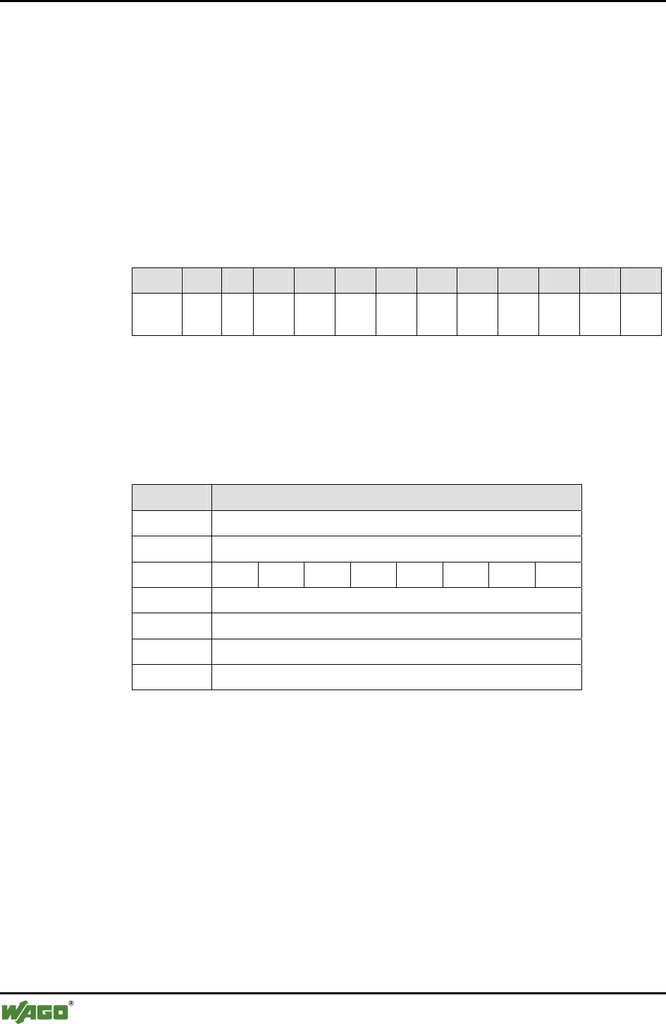
84 • Fieldbus-specific Additions
CANopen
WAGO-I/O-SYSTEM 750
I/O Modules
PDOs 1 through 4 are, according to the standard for digital and analog mod-
ules, reserved and occupied. Additional PDOs are not necessary for digital and
analog modules. With the exception of a Bluetooth® module, no additional
special modules are plugged in.
The Bluetooth® module uses a process image of 12 bytes with a mailbox size
of 6 bytes. The mailbox is unmasked.
Therefore, the 5th and 6th PDOs are allocated to this module. The 6th PDO
contains only 4 bytes of process data. The 7th PDO and the following PDOs
are free for additional modules.
Data in the process image
Byte 1 2 3 4 5 6 7 8 9 10 11 12
Con-
tent:
C/S - MB1 MB2 MB3 MB4 MB5 MB6 D1 D2 D3 D4
C/S Control/status byte
MB1 – MB6 Mailbox data bytes 1…6
D1 – D4 Process data bytes 1…4
Entries in the object directory
Sub Bytes
Sub0 6 (number of subindices)
Sub1 8 (length of the mailbox character chain (Sub 2))
Sub2 C/S - MB1 MB2 MB3 MB4 MB5 MB6
Sub3 D1 (process data flags + slave 1/1A)
Sub4 D2 (process data slave 2/2A + slave 3/3A)
Sub5 D3 (process data slave 4/4A + slave 5/5A)
Sub6 D4 (process data slave 6/6A + slave 7/7A)
With this configuration, the Bluetooth® bits and process data of 7 Bluetooth®
slaves can be transmitted.
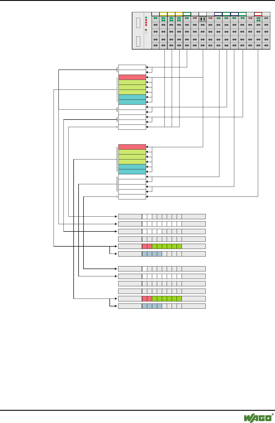
Fieldbus-specific Additions • 85
CANopen
WAGO-I/O-SYSTEM 750
I/O Modules
402
DI DI DI DI DI DI
402 402 452 602 644 602
602 600550 550
452 452 504
1234 5678 910111213
AI AI BT AO AO AI AI AO AO AI AI DO DO
750-337
Input image
Output image
Status byte
Mailbox
Mailbox
Mailbox
Data
Mailbox
Mailbox
Mailbox
Data
Data
Control byte
AI1 C1
AI1 2C
AI2 1C
AI2 2C
AI3 1C
AI3 2C
DI1 1-DI3 4CC
AO1 C1
AO1 C2
AO2 C1
AO2 C2
DO1 C1-C4
Data
TxPDO 1, DI1 C1 - DI3 C4
TxPDO 2, AI1 C1 - AI2 C2
TxPDO 3, AI3 C1 - C2
TxPDO 4, not used
TxPDO 5, Status byte + Mailbox
TxPDO 6, Data byte1-4
RxPDO 1, DO1 C1 - C4
RxPDO 2, AO1 C1 - AO2 C2
RxPDO 3, not used
RxPDO 4, not used
RxPDO 5, Control byte + Mailbox
RxPDO 6, Data byte1-4
Figure 37: PDO allocation of a Bluetooth® module g064469e

86 • Fieldbus-specific Additions
DeviceNet
WAGO-I/O-SYSTEM 750
I/O Modules
5.2 DeviceNet
5.2.1 Process Image Access
The DeviceNet master can access the Bluetooth® data in two ways.
With predefined instances of the assembly object, digital and analog input and
output data of a node are transmitted with a command to, or from, the master.
The application in the master can then address the data in the memory. The
data is stored in the master as it is for mapping in the coupler/controller. The
byte-oriented module data (analog modules and special modules) and the bit-
oriented module data (digital modules) are separated according to input and
output image in the memory in "arrays of byte". Therefore, the corresponding
array and associated memory address can be determined from module type.
The data in the Bluetooth® module can be directly addressed with the analog
input point object or the analog output point object. The instance number of
the respective object is based on the position of the module in the node.
5.2.1.1 Example
A node contains the following modules with input and output process image:
3 x 750-402 for every 4 bits of input data,
1 x 750-452 4 bytes of input data,
1 x 750-644 12 bytes of input and 12 bytes of output data,
1 x 750-550 4 bytes of output data,
1 x 750-452 4 bytes of input data,
1 x 750-550 4 bytes of output data,
1 x 750-452 4 bytes of input data,
1 x 750-504 4 bits of output data.
The Bluetooth® module uses a process image of 12 bytes with a mailbox size
of 6 bytes. The mailbox is unmasked.
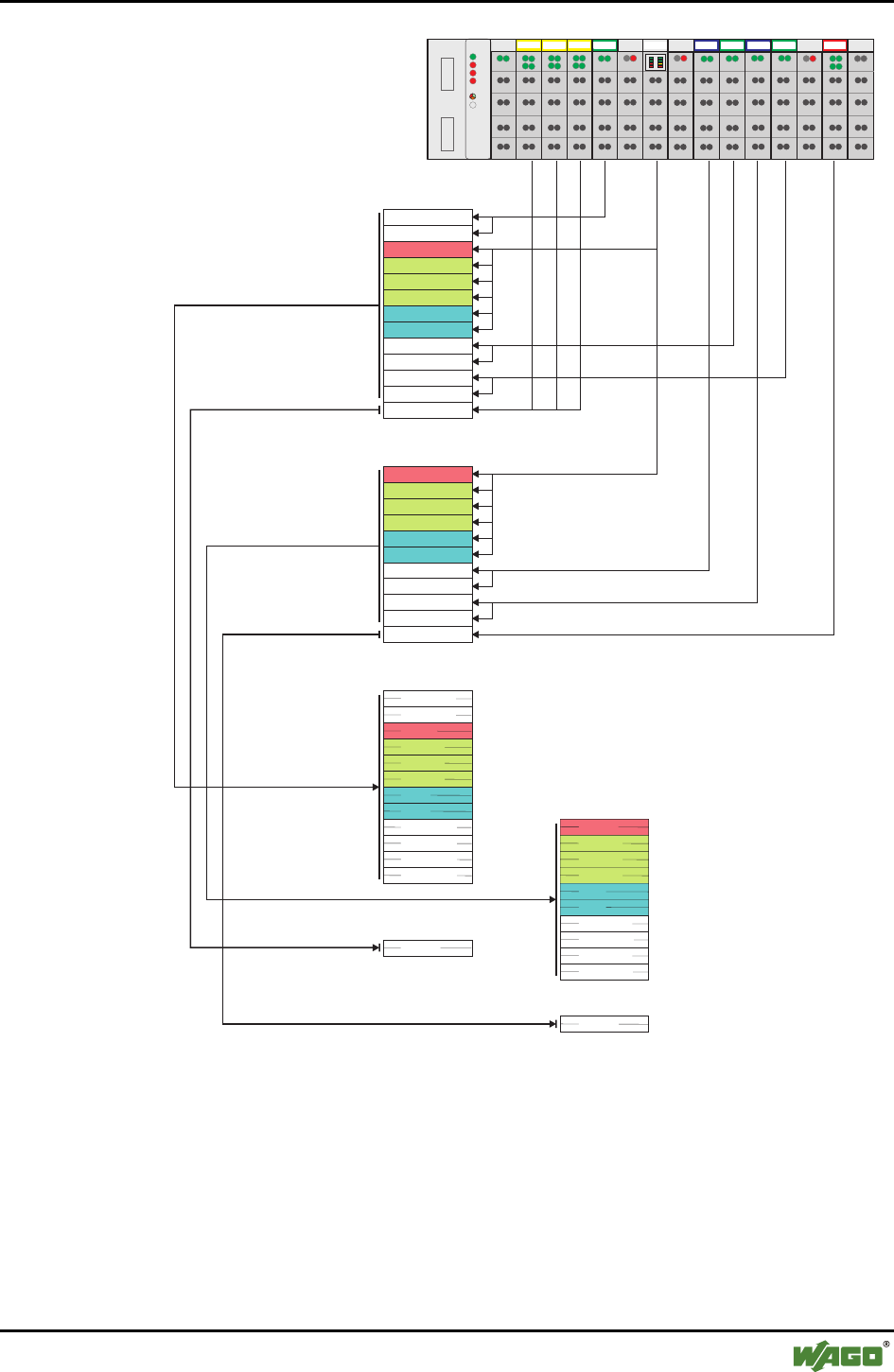
Fieldbus-specific Additions • 87
DeviceNet
WAGO-I/O-SYSTEM 750
I/O Modules
402
DI DI DI DI DI DI
402 402 452 602 644 602
602 600550 550
452 452 504
1234 5678 910111213
AI AI BT AO AO AI AI AO AO AI AI DO DO
750-306
Input image (in words)
Output image (in words)
Status
Mailbox
Mailbox
Mailbox
Data
Mailbox
Mailbox
Mailbox
Data
Data
Control
Channel 1
Channel 2
Channel 1
Channel 2
Channel 1
Channel 2
DI 1-12
Channel 1
Channel 2
Channel 1
Channel 2
DO 1-4
DI 1-12
Status
Mailbox
Mailbox
Mailbox
Data
Data
Channel 1
Channel 2
Channel 1
Channel 2
Channel 1
Channel 2
Data
Mailbox
Mailbox
Mailbox
Data
Data
Control
Channel 1
Channel 2
Channel 1
Channel 2
DO 1-4
Array of Byte
Array of Byte
Array of Byte
Array of Byte
Analog input data (in bytes)
Analog output data (in bytes)
Digital output data
Digital input data
Analog input data
Analog output data
Digital input data
Digital output data
Assembly Object
Instance 9
Assembly Object
Instance 8
Assembly Object
Instance 3
Assembly Object
Instance 2
Figure 38: Array allocation of a Bluetooth® module g064470e

88 • Fieldbus-specific Additions
ETHERNET
WAGO-I/O-SYSTEM 750
I/O Modules
5.3 ETHERNET
5.3.1 Process Image Access
5.3.1.1 MODBUS Protocol
Bluetooth® module data is accessed with functions for reading and writing reg-
isters. Registers can be read and written in block or individually. A register in-
cludes two bytes.
The allocation of the register to the input and output data of the module is de-
pendent on the order and type of modules.
Separated according to input and output data, the registers are first written in
ascending order with the data of the byte-oriented modules (analog and special
modules) and then with the data of the bit-oriented modules (digital modules).
The first input or output register allocated to a Bluetooth® module contains the
status or control byte and an empty byte.
Connected to this are the registers for the unmasked mailbox.
If the mailbox is set to be superimposable, these registers contain mailbox or
process data. Furthermore, registers allocated to a Bluetooth® module contain
the remaining process data.
In access by blocks, the data is transmitted with a command (e.g., FC 3 – Read
Multiple Registers, FC 16 – Write Multiple Registers or FC 23 – Read/Write
Multiple Registers). In the function call up, the start address and the number
of registers to be transmitted are given. Access to the individual data then oc-
curs in the superordinate control.
The command FC 6 (Write Single Register) or the commands named above
are used for direct access to individual registers by setting the number of reg-
isters to be transmitted to one.
5.3.1.1.1 Example
A node contains the following modules with input and output process image:
3 x 750-402 for every 4 bits of input data,
1 x 750-452 4 bytes of input data,
1 x 750-644 12 bytes of input and 12 bytes of output data,
1 x 750-550 4 bytes of output data,
1 x 750-452 4 bytes of input data,
1 x 750-550 4 bytes of output data,
1 x 750-452 4 bytes of input data,
1 x 750-504 4 bits of output data.
The Bluetooth® module uses a process image of 12 bytes with a mailbox size
of 6 bytes. The mailbox is unmasked.
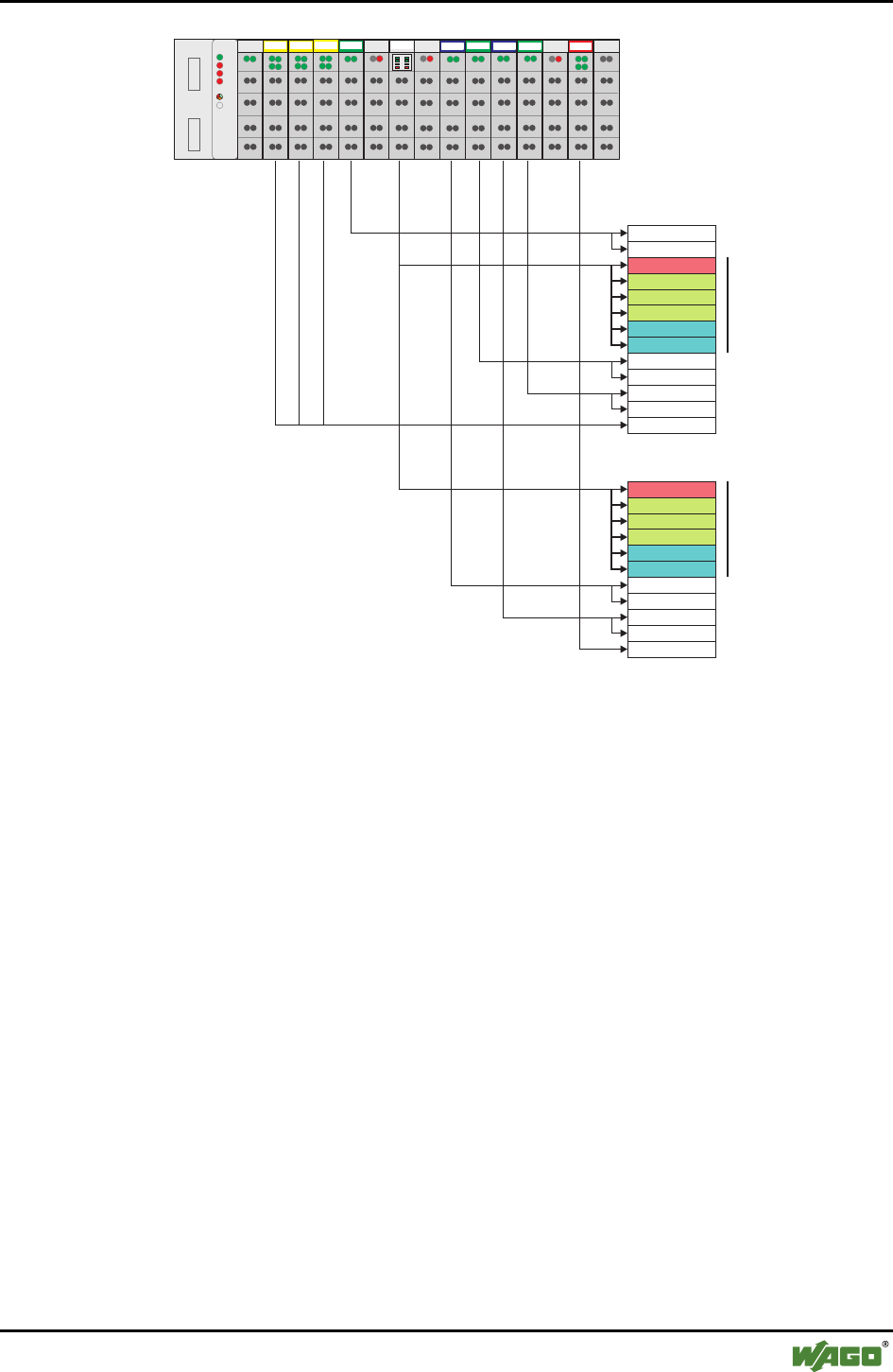
Fieldbus-specific Additions • 89
ETHERNET
WAGO-I/O-SYSTEM 750
I/O Modules
402
DI DI DI DI DI DI
402 402 452 602 644 602
602 600550 550
452 452 504
1234 5678 910111213
AI AI BT AO AO AI AI AO AO AI AI DO DO
750-342
0
1
2
3
4
5
6
7
8
9
10
11
12
0
1
2
3
4
5
6
7
8
9
10
Input register
Output register
Status
Mailbox
Mailbox
Mailbox
Data
Mailbox
Mailbox
Mailbox
Data
Data
Data
Control
Access to data with FC 3,
Start address 2, Length 6
Access to data with FC 16,
Start address 0, Length 6
Figure 39: Register allocation of a Bluetooth® module g064471e
The input data of the Bluetooth® module is mapped to input registers 2
through 7. Register 2 contains the status byte and an empty byte. Register 3
through 5 contain the mailbox data. Register 6 and 7 contain the process data.
The data can be read with FC 3 (start address 2, length 6.
The output data is mapped to output register 0 through 5. Register 0 contains
the control byte and an empty byte. Registers 1 through 3 contain the mailbox
data. Register 4 and 5 contain the process data.
The data can be written with FC 16 (start address 0, length 6).

90 • Fieldbus-specific Additions
ETHERNET
WAGO-I/O-SYSTEM 750
I/O Modules
5.3.1.2 EtherNet/IP Protocol
With the EtherNet/IP protocol, Bluetooth® data can be accessed in two ways.
In predefined instances of the assembly object, digital and analog input and
output data of a node are transmitted with a command to, or from, the Blue-
tooth® module. The application in the Bluetooth® module can then address the
data in the memory. The data is stored in the module in the same manner as
when mapping in the coupler/controller. The byte-oriented module data (ana-
log modules and special modules) and the bit-oriented module data (digital
modules) are stored in the memory separately according to input and output
image. The memory address can then be determined from the type of module
and its position.
The data in the Bluetooth® module can be directly addressed with the analog
input point object or the analog output point object. The instance number of
the respective object is based on the position of the module in the node.
5.3.1.2.1 Example
A node contains the following modules with input and output process image:
3 x 750-402 for every 4 bits of input data,
1 x 750-452 4 bytes of input data,
1 x 750-644 12 bytes of input and 12 bytes of output data,
1 x 750-550 4 bytes of output data,
1 x 750-452 4 bytes of input data,
1 x 750-550 4 bytes of output data,
1 x 750-452 4 bytes of input data,
1 x 750-504 4 bits of output data.
The Bluetooth® module uses a process image of 12 bytes with a mailbox size
of 6 bytes. The mailbox is unmasked.

Fieldbus-specific Additions • 91
ETHERNET
WAGO-I/O-SYSTEM 750
I/O Modules
402
DI DI DI DI DI DI
402 402 452 602 644 602
602 600550 550
452 452 504
1234 5678 910111213
AI AI BT AO AO AI AI AO AO AI AI DO DO
750-341
Input image
Output image
Status
Mailbox
Mailbox
Mailbox
Data
Mailbox
Mailbox
Mailbox
Data
Data
Control
Channel 1
Channel 2
Channel 1
Channel 2
Channel 1
Channel 2
DI 1-12
Channel 1
Channel 2
Channel 1
Channel 2
DO 1-4
DI 1-12
Status
Mailbox
Mailbox
Mailbox
Data
Data
Channel 1
Channel 2
Channel 1
Channel 2
Channel 1
Channel 2
Data
Mailbox
Mailbox
Mailbox
Data
Data
Control
Channel 1
Channel 2
Channel 1
Channel 2
DO 1-4
Array of Byte
Array of Byte
Array of Byte
Array of Byte
Analog Input data
Analog output data
Digital output data
Digital input data
Analog input data
Analog output data
Digital input data
Digital input data
Assembly Object
Instance 109
Assembly Object
Instance 108
Assembly Object
Instance 103
Assembly Object
Instance 102
Figure 40: Array allocation Bluetooth® module g065572e

92 • Fieldbus-specific Additions
PROFIBUS-DP
WAGO-I/O-SYSTEM 750
I/O Modules
5.4 PROFIBUS-DP
5.4.1 Process Image Access
The Bluetooth® module data is accessed through the process image of the
PROFIBUS master. To ensure data consistency at a data width of 12 to 48
bytes, the data must be mapped with system functions for the consistent read-
ing and writing to an appropriately large, reserved flag area. The data in this
flag area can then be processed by the control program.
5.4.1.1 Example
A node contains the following modules with input and output process image:
3 x 750-402 for every 4 bits of input data,
1 x 750-452 4 bytes of input data,
1 x 750-644 12 bytes of input and 12 bytes of output data,
1 x 750-550 4 bytes of output data,
1 x 750-452 4 bytes of input data,
1 x 750-550 4 bytes of output data,
1 x 750-452 4 bytes of input data,
1 x 750-504 4 bits of output data.
The Bluetooth® module uses a process image of 12 bytes with a mailbox size
of 6 bytes. The mailbox is unmasked.
The input/output configuration in the PROFIBUS master can be structured as
follows:
no. Function Module Process image of the master *
Identifier inputs outputs
Digital input EB12.0
Digital input EB12.1
Digital input EB12.2
1
Digital input
750-402 4 DI/24 V DC/3.0 ms
0x10
EB12.3
Digital input EB12.4
Digital input EB12.5
Digital input EB12.6
2
Digital input
*750-402 4 DI/24 V DC/3.0 ms
0x00
EB12.7
Digital input EB13.0
Digital input EB13.1
Digital input EB13.2
3
Digital input
750-402 4 DI/24 V DC/3.0 ms
0x10
EB13.3

Fieldbus-specific Additions • 93
PROFIBUS-DP
WAGO-I/O-SYSTEM 750
I/O Modules
no. Function Module Process image of the master *
Identifier inputs outputs
Analog input EW 0 - 4
Analog input
750-452 2 AI/0…20 mA/diff.
0x51 EW 2 -
5 Potential input Potential input - -
Control/status byte EW 20 AW 10
Mailbox EW 22 AW 12
Mailbox EW 24 AW 14
Mailbox EW 26 AW 16
Data EW 28 AW 18
6
Data
750-644 Bluetooth® RF Trans-
ceiver
12 byte process image
0x8B
EW 30 AW 20
7 Potential input Potential input - -
Analog output - AW 0 8
Analog output
750-550 2 AO/0…10 V
0x61 - AW 2
Analog input EW 4 - 9
Analog input
750-452 2 AI/0…20 mA/diff.
0x51 EW 6 -
Analog output - AW 4 10
Analog output
750-550 2 AO/0…10 V
0x61 - AW 6
Analog input EW 8 - 11
Analog input
750-452 2 AI/0…20 mA/diff.
0x51 EW 10 -
12 Potential input Potential input - -
Digital output - AB8.0
Digital output - AB8.1
Digital output - AB8.2
13
Digital output
750-504 4 DO/24 V DC/0.5 A
0x20
- AB8.3
14 End Module End Module - -
* The addresses stated in the table correspond to the process data allocation given in the
configuration.
If the PROFIBUS master is a Siemens S7 SPS, the data is consistently read
and written with the system functions SFC14 and SFC15.
To map the input data EW20 through EW30 to the flag area MW100 through
MW110, the functions are accessed as follows:
CALL SFC 14
LADDR := W#16#14 (read from input address EW20)
RECORD := P#M100.0 BYTE 12 (write 12 bytes beginning with MW100)
RET_VAL := MW112 (write error messages after MW112)
To map the output data AW10 through AW20 to the flag area MW114
through MW124, the functions are accessed as follows:
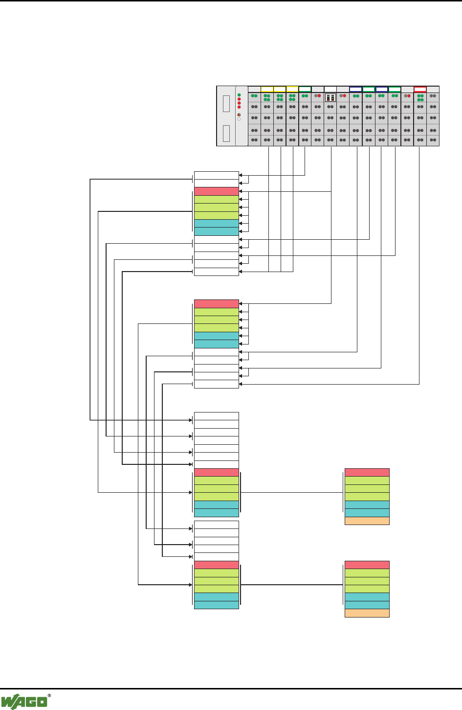
94 • Fieldbus-specific Additions
PROFIBUS-DP
WAGO-I/O-SYSTEM 750
I/O Modules
CALL SFC 15
LADDR := W#16#0A (write from output address AW10)
RECORD := P#M114.0 BYTE 12 (read 12 bytes beginning with MW114)
RET_VAL := MW126 (write error messages after MW126)
402
DI DI DI DI DI DI
402 402 452 602 644 602
602 600550 550
452 452 504
1234 5678 910111213
AI AI BT AO AO AI AI AO AO AI AI DO DO
750-333
CALL SFC 14
LADDR := W#16#14
RET_VAL := MW112
RECORD := P# M100.0 BYTE 12
CALL SFC 15
LADDR := W#16#0A
RET_VAL := MW126
RECORD := P# M114.0 BYTE 12
Input image
Output image
Status
Mailbox
Mailbox
Mailbox
Data
Mailbox
Mailbox
Mailbox
Data
Data
Control
AI1 C1
AI1 2C
AI2 1C
AI2 2C
AI3 1C
AI3 2C
DI1 1-DI3 4CC
AO1 C1
AO1 C2
AO2 C1
AO2 C2
DO1 C1-C4
Data
Process image of the PROFIBUS master
IW0
IW2
IW4
IW6
IW8
IW10
IW12
IW20
IW22
IW24
IW26
IW28
IW30
QW0
QW2
QW4
QW6
QW8
QW10
QW12
QW14
QW16
QW18
QW20
MW100
MW102
MW104
MW106
MW108
MW110
MW114
MW116
MW118
MW120
MW122
MW124
MW112
MW126
Figure 41: Process image allocation of a Bluetooth® module g064473e

Fieldbus-specific Additions • 95
LON
WAGO-I/O-SYSTEM 750
I/O Modules
5.5 LON
The Bluetooth® module 750-644 is supported by the LON Fieldbus Coupler
750-319 and by the programmable LON Fieldbus Controller 750-819.
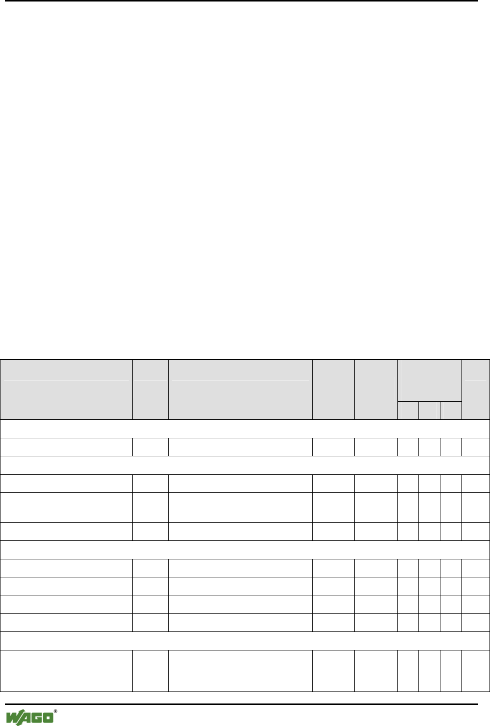
96 • Appendix
Mailbox Commands
WAGO-I/O-SYSTEM 750
I/O Modules
6 Appendix
6.1 Mailbox Commands
This appendix provides an overview of all available mailbox commands,
sorted according to groups and opcodes (see Appendix 6.1.1) and according to
mailbox commands (see Appendix 6.1.2).
Which commands can be executed with which mailbox size is indicated by
symbols as follows:
● Available
The command can be executed.
(●) Available to a limited extent
Execution of the command is possible, but only as much
data as is possible for the current mailbox size is returned.
- Not available
The command cannot be executed.
6.1.1 Overview Sorted According to Groups and Opcodes
May be
executed
with mailbox
Mailbox commands Opcode Description Length
query
Length
response
6 12 18
Page
General commands
IDLE 0x00 No job 2 2 ● ● ● 104
Block transfer
DLD_START 0x01 Start transfer 6 3 ● ● ● 105
DLD_CONT 0x02 Continue transfer 2/6/12/
18
6/12/18 ● ● ● 107
DLD_END 0x03 End transfer 5 6 ● ● ● 109
Maintenance and firmware
RebootHost 0x10 Warm start host 2 2 ● ● ● 111
FlashRebootHost 0x11 Backup configuration, warm start 2 2 ● ● ● 112
GetHostFwVersion 0x12 Read host firmware version 3 6 ● ● ● 113
GetBbFwVersion 0x13 Read baseband firmware version 2 6/12 (●) ● ● 115
Process image
SetRemotePiSize 0x32 Determine the size of a slot for
data transfer in the master process
image
4 2 ● ● ● 116

Appendix • 97
Mailbox Commands
WAGO-I/O-SYSTEM 750
I/O Modules
May be
executed
with mailbox
Mailbox commands Opcode Description Length
query
Length
response
6 12 18
Page
GetRemotePiMapping 0x33 Query the remote process image
parameters within the master
process image
3 6 ● ● ● 118
Device configuration
GetLocalDeviceName 0x40 Read device names 2 3…18 (●) (●)● 120
SetLocalDeviceName 0x41 Set device names 3…18 2 (●) (●)● 121
GetLocalMacID 0x42 Read MAC-ID 2 8 - ● ● 123
GetLocalIPAddress 0x43 Read IP address 2 6 ● ● ● 124
SetLocalIPAddress 0x44 Set IP address 6 2 ● ● ● 125
GetLocalSubnetMask 0x45 Read subnet mask 2 6 ● ● ● 126
SetLocalSubnetMask 0x46 Write subnet mask 6 2 ● ● ● 127
GetLocalDeviceClass 0x47 Read local WAGO device class 2 4 ● ● ● 128
SetLocalDeviceClass 0x48 Write CoD settings 4 2 ● ● ● 129
GetLocalOperationMode 0x49 Read operation mode 2 4 ● ● ● 130
SetLocalOperationMode 0x4A Set operation mode 2 4 ● ● ● 131
GetLocalEncryptionMode 0x4D Read encryption mode 2 3 ● ● ● 133
SetLocalEncryptionMode 0x4E Set encryption mode 3 2 ● ● ● 134
GetLocalAuthenticationMode 0x4F Read authentication mode 2 3 ● ● ● 135
SetLocalAuthenticationMode 0x50 Write authentication mode 2 2 ● ● ● 136
GetLocalPassphrase 0x51 Read local Bluetooth® password 2 7…18 - (●)(●)138
SetLocalPassphrase 0x52 Write local Bluetooth® password 7…18 2 - (●)(●)139
EraseLocalAuthentication 0x53 Delete authentication settings 2 2 ● ● ● 141
GetLocalDeviceConfigLen 0x54 Read length of the configuration 2 4 ● ● ● 142
GetLocalDeviceRole 0x55 Read device role 2 3 ● ● ● 143
SetLocalDeviceRole 0x56 Write device role 3 2 ● ● ● 144
SetFactorySettings 0x57 Rewrite factory settings 2 2 ● ● ● 145
Network
ScanRemoteDevices 0x80 Search for remote Bluetooth®
device in the wireless network
5 2 ● ● ● 146
GetRemoteDeviceMacID 0x81 Read MAC-ID of a remote Blue-
tooth® device
2 9 - ● ● 148
GetRemoteDeviceName 0x82 Read device name of a remote
Bluetooth® device
2 6…18 (●) (●)(●)150
AllowRemoteDevice 0x83 Enter remote device in authoriza-
tion table
9 2 - ● ● 152

98 • Appendix
Mailbox Commands
WAGO-I/O-SYSTEM 750
I/O Modules
May be
executed
with mailbox
Mailbox commands Opcode Description Length
query
Length
response
6 12 18
Page
GetAllowedRemoteDevices 0x84 Read back remote device from
the authorization table
2 8 - ● ● 154
BindRemoteDevice 0x85 Activate authorized device 3 2 ● ● ● 156
UnbindRemoteDevice 0x86 Deactivate authorized device 3 2 ● ● ● 157
GetBoundRemoteDevices 0x87 Read access authorization for
remote devices
2 3 ● ● ● 159
GetConnectionQoS 0x88 Read Quality-of-Service settings 2 3 ● ● ● 160
SetConnectionQoS 0x89 Set Quality-of-Service 4 2 ● ● ● 161
GetReconnectionTimePeriod 0x8A Read time between attempts to
establish connection
2 4 ● ● ● 163
SetReconnectionTimePeriod 0x8B Set time between attempts to
establish connection
4 2 ● ● ● 164
GetUserfriendlyName 0x8C Read user-friendly name for a
slave entry
2 3…18 (●) (●) ● 166
SetUserfriendlyName 0x8D Set user-friendly name to a slave
entry
3…18 2 (●) (●) ● 168
Diagnostics
GetLocalDeviceStatus 0xD0 Read status of the local bus
module
2 6 ● ● ● 170
GetNetworkStatus 0xD1 Read network status 2 4 ● ● ● 172
GetStatusMessage 0xD2 Read status reports 4 6 ● ● ● 174
GetLinkQuality 0xD5 Read connection quality 3 3 ● ● ● 179
GetLinkSignalStrength 0xD7 Read signal strength 3 3 ● ● ● 181
GetAvailableChannelMap 0xD8 Read available wireless channels 3 12 - ● ● 183
SetLED 0xD9 Test LED function 5 2 ● ● ● 185
MirrorMailboxCommand 0xDA Mirror mailbox command for test 6/12/18 6/12/18 ● ● ● 187
GetLocalUpTime 0xDB Read operating time of the
module
6/8 6/8 (●) ● ● 188

Appendix • 99
Mailbox Commands
WAGO-I/O-SYSTEM 750
I/O Modules
6.1.2 Overview Sorted According to Mailbox Commands
May be
executed
with mailbox
Mailbox command Opcode Description Length
query
Length
re-
sponse
6 12 18
Page
AllowRemoteDevice 0x83 Enter remote device in authoriza-
tion table
9 2 - ● ● 152
BindRemoteDevice 0x85 Activate authorized device 3 2 ● ● ● 156
DLD_CONT 0x02 Continue transfer 2/6/12
/18
6/12
/18
● ● ● 107
DLD_END 0x03 End transfer 5 6 ● ● ● 109
DLD_START 0x01 Start transfer 6 3 ● ● ● 105
EraseLocalAuthentication 0x53 Delete authentication settings 2 2 ● ● ● 141
FlashRebootHost 0x11 Backup configuration, warm start 2 2 ● ● ● 112
GetAllowedRemoteDevices 0x84 Read back remote device from the
authorization table
2 8 - ● ● 154
GetAvailableChannelMap 0xD8 Read available wireless channels 3 14 - - ● 183
GetBbFwVersion 0x13 Read baseband firmware version 2 6/12 (●) ● ● 115
GetBoundRemoteDevices 0x87 Read access authorization for
remote devices
2 3 ● ● ● 159
GetConnectionQoS 0x88 Read Quality-of-Service settings 2 3 ● ● ● 160
GetHostFwVersion 0x12 Read host firmware version 3 6 ● ● ● 113
GetLinkQuality 0xD5 Read connection quality 3 3 ● ● ● 179
GetLinkSignalStrength 0xD7 Read signal strength 3 3 ● ● ● 181
GetLocalAuthenticationMode 0x4F Read authentication mode 2 3 ● ● ● 135
GetLocalDeviceClass 0x47 Read local WAGO device class 2 4 ● ● ● 128
GetLocalDeviceConfigLen 0x54 Read length of the configuration 2 4 ● ● ● 142
GetLocalDeviceName 0x40 Read device names 2 3…18 (●) (●)● 120
GetLocalDeviceRole 0x55 Read device role 2 3 ● ● ● 143
GetLocalDeviceStatus 0xD0 Read status of the local bus mod-
ule
2 6 ● ● ● 170
GetLocalEncryptionMode 0x4D Read encryption mode 2 3 ● ● ● 133
GetLocalIPAddress 0x43 Read IP address 2 6 ● ● ● 124
GetLocalMacID 0x42 Read MAC-ID 2 8 - ● ● 123
GetLocalOperationMode 0x49 Read operation mode 2 4 ● ● ● 130
GetLocalPassphrase 0x51 Read local Bluetooth® password 2 7…18 - (●)(●)138
GetLocalSubnetMask 0x45 Read subnet mask 2 6 ● ● ● 126
GetLocalUpTime 0xDB Read operating time of the module 6/8 6/8 (●) ● ● 188
GetNetworkStatus 0xD1 Read network status 2 4 ● ● ● 172

100 • Appendix
Mailbox Commands
WAGO-I/O-SYSTEM 750
I/O Modules
May be
executed
with mailbox
Mailbox command Opcode Description Length
query
Length
re-
sponse
6 12 18
Page
GetReconnectionTimePeriod 0x8A Read time between attempts to
establish connection
2 4 ● ● ● 163
GetRemoteDeviceMacID 0x81 Read MAC-ID of a remote Blue-
tooth® device
2 9 - ● ● 148
GetRemoteDeviceName 0x82 Read device name of a remote
Bluetooth® device
2 6…18 (●) (●) (●)150
GetRemotePiMapping 0x33 Query the remote process image
parameters within the master proc-
ess image
3 6 ● ● ● 118
GetStatusMessage 0xD2 Read status reports 4 6 ● ● ● 174
GetUserfriendlyName 0x8C Read user-friendly name for a
slave entry
2 3…18 (●) (●) ● 166
IDLE 0x00 No job 2 2 ● ● ● 104
MirrorMailboxCommand 0xDA Mirror mailbox command for test 6/12
/18
6/12
/18
● ● ● 187
RebootHost 0x10 Warm start host 2 2 ● ● ● 111
ScanRemoteDevices 0x80 Search for remote Bluetooth®
device in the wireless network
5 2 ● ● ● 146
SetConnectionQoS 0x89 Set Quality-of-Service 4 2 ● ● ● 161
SetFactorySettings 0x57 Rewrite factory settings 2 2 ● ● ● 145
SetLED 0xD9 Test LED function 5 2 ● ● ● 185
SetLocalAuthenticationMode 0x50 Write authentication mode 2 2 ● ● ● 136
SetLocalDeviceClass 0x48 Write CoD settings 4 2 ● ● ● 129
SetLocalDeviceName 0x41 Set device names 3…18 2 (●) (●) (●)121
SetLocalDeviceRole 0x56 Write device role 3 2 ● ● ● 144
SetLocalEncryptionMode 0x4E Set encryption mode 3 2 ● ● ● 134
SetLocalIPAddress 0x44 Set IP address 6 2 ● ● ● 125
SetLocalOperationMode 0x4A Set operation mode 2 4 ● ● ● 131
SetLocalPassphrase 0x52 Read local Bluetooth® password 7…18 2 - (●) (●)139
SetLocalSubnetMask 0x46 Write subnet mask 6 2 ● ● ● 127
SetReconnectionTimePeriod 0x8B Set time between attempts to es-
tablish connection
4 2 ● ● ● 164
SetRemotePiSize 0x32 Determine the size of a slot for
data transfer in the master process
image
4 2 ● ● ● 116
SetUserfriendlyName 0x8D Set user-friendly name to a slave
entry
3…18 2 (●) (●) ● 168
UnbindRemoteDevice 0x86 Deactivate authorized device 3 2 ● ● ● 157

Appendix • 101
Return Values of Mailbox Commands
WAGO-I/O-SYSTEM 750
I/O Modules
6.2 Return Values of Mailbox Commands
The following standard values are defined for the return values
(MBX_RESULT) of mailbox commands:
Label Return
value
Description
MBX_CMD_OK 0x00 Successful execution
MBX_CMD_GENERAL_ERROR 0x01 General error
MBX_CMD_DENIED_UNKNOWN 0x02 Unknown command
MBX_CMD_OUT_OF_RANGE 0x03 Values outside of the valid range
(overrun or underrun)
MBX_CMD_INVALID_ARG 0x04 False or invalid argument
MBX_CMD_INTERNAL_ERROR 0x05 Internal fault
MBX_CMD_TIMEOUT 0x06 Time overrun of the command
MBX_CMD_DENIED_NOT_APPLICABLE 0x07
Prerequisites for command not ful-
filled: false operation mode, false
device role or necessary precursor
command not executed
MBX_CMD_DENIED_NOT_IMPLEMENTED 0x08 Command reserved for later imple-
mentation
MBX_CMD_DENIED_MBX_TOO_SMALL 0x09 Mailbox too small for return value
MBX_CMD_DENIED_BUSY 0x0A Current or precursor command being
executed, no valid data is available
yet. Recommendation: call up com-
mand again after a short waiting
period.
MBX_CMD_INVALID_CONFIGURATION 0x0B System or network configuration is
defective
All mailbox commands use these return values to signal the status of the
command execution. If individual return values offer additional interpretations
for specific mailbox commands, this is explained in more detail in the descrip-
tion of the respective command.
In principle, the first return value with a mirrored mailbox command and tog-
gle bit is considered a valid response. As soon as this happens, the next mail-
box command can be executed. Many commands result in a restart of the
module. If a mailbox command that triggers a restart is not replaced by an-
other command after receiving the response, the module recognizes the unal-
tered, existing command when it restarts. The command is rejected with
MBX_CMD_DENIED_BUSY to prevent an endless loop of resets. This of-
fers the possibility of determining the successful conclusion of a reset by
monitoring change of the return value.

102 • Appendix
Mailbox Command References
WAGO-I/O-SYSTEM 750
I/O Modules
6.3 Mailbox Command References
In this section, the requirements for the execution of each mailbox command
are represented as follows:
Mailbox size (6, 12 or 18 bytes)
● Available
The command can be executed.
(●) Available to a limited extent
Execution of the command is possible, but only as much
data as is possible for the current mailbox size is returned.
- Not available
The command cannot be executed.
Operating mode (configuration mode/communication mode with real-
time or ad hoc profile)
● Available
The command can be executed.
- Not available
The command cannot be executed.
Device role (master, slave)
● Available
The command can be executed.
- Not available
The command cannot be executed.
Save configuration
● With this command, module settings are changed. This change is first undertaken on a
temporary image of the module configuration. The temporary image is loaded during a
restart of the module from the non-temporary image. To update the non-temporary image,
execute a warm start (see Appendix 6.3.3.2, "FlashRebootHost"). Alternatively, you can
change the operating mode (see Appendix, "SetLocalOperationMode", 6.3.5.11).
This will automatically execute a warm start (see Figure 24).
- No data is saved for this command.
Restart
● The module executes a restart after performing command.
- The module executes no restart performing the command.

Appendix • 103
Mailbox Command References
WAGO-I/O-SYSTEM 750
I/O Modules
In addition, configuration of the bytes is described during query and response
with arguments and return values. If no return values are present, the related
tables are presented in gray.
Note
If the query is smaller than the mailbox, the remaining bytes in the mailbox
should be filled with 0x00 during the query.
If the size of the response is smaller than the size of the mailbox, the remain-
ing bytes in the mailbox of the module are filled with 0x00.

104 • Appendix
Mailbox Command References
WAGO-I/O-SYSTEM 750
I/O Modules
6.3.1 General Commands
6.3.1.1 No Task (IDLE, 0x00)
If the opcode = 0x00, no task is performed. This command is available in all
operating modes for all mailbox sizes.
Conditions
Mailbox size Operating mode/profile Device role
6 12 18 Config. Real-
time Ad hoc Master Slave
Save
config. Restart
● ● ● ● ● ● ● ● - -
Request
Byte 27 26 25 24 23 22 21 20
0 MBX_IDLE
1 T -
Response
Byte 27 26 25 24 23 22 21 20
0 MBX_IDLE
1 T MBX_RESULT
Return values
Parameter Value Description
- - -
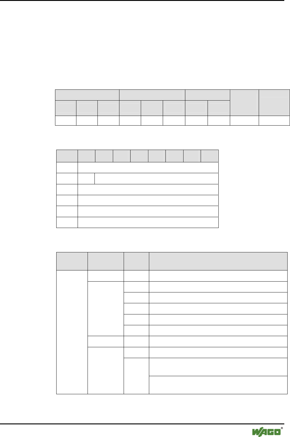
Appendix • 105
Mailbox Command References
WAGO-I/O-SYSTEM 750
I/O Modules
6.3.2 Block Transfer
6.3.2.1 Download Start of a Block (DLD_START, 0x01)
The block transfer starts with the call up. A new DLD_START with no previ-
ous DLD_END breaks the transfer off and initializes a new transfer. The
command block is concluded by DLD_END.
Conditions
Mailbox size Operating mode/profile Device role
6 12 18 Config. Real-
time Ad hoc Master Slave
Save
config. Restart
● ● ● ● - - ● ● - -
Request
Byte 27 26 25 24 23 22 21 20
0 MBX_DLD_START
1 T -
2 MBX_MB3
3 MBX_MB4
4 MBX_MB5
5 MBX_MB6
Arguments
Operating
mode
Parameter Value Description
MBX_MB3 0x01 Block type: RAM block
0x06 Write / read configuration
0x07 Read query result
0x09 Read name of the remote bus module
0x0A Read / write complete name of the local bus module
MBX_MB4
0x0B Read / write password of the local bus module
MBX_MB5 0x00 Number of the block in the whole transmission (LSB)
bit 0…5 Number of the block in the whole transmission (MSB)
0x80 - download, write to the module
(bit 6=0, bit 7=1)
Configur-
ation mode
MBX_MB6
bit 6, 7
0xC0 - upload, read from the module
(bit 6=1, bit 7=1)

106 • Appendix
Mailbox Command References
WAGO-I/O-SYSTEM 750
I/O Modules
Response
Byte 27 26 25 24 23 22 21 20
0 MBX_DLD_START
1 T MBX_RESULT
2 MBX_DLD_RESULT
Return values
Parameter Value Description
DLD_OK (0x00) No error. The block transfer has been started.
DLD_DOWNLOAD_
NOT_STARTED (0x01)
The block transfer has not been started. An
undefined block is supposed to be transmitted.
DLD_OK_ABORTED
(0x02)
A block transfer is currently active. No new
transfer is being started.
DLD_ERROR (0x31) A non-supported writing or ready operation
has been started.
MBX_DLD_
RESULT
DLD_ERROR_TABLE_
READ_ONLY (0x32)
Protected area of configuration should receive
download.
MBX_CMD_GENERAL_
ERROR
Configuration mode: an error has occurred.
More detailed information in
MBX_DLD_RESULT
MBX_RESULT
MBX_CMD_DENIED_NOT
_APPLICABLE
The command has been called up in commu-
nication mode.
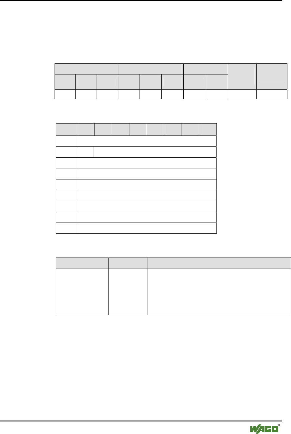
Appendix • 107
Mailbox Command References
WAGO-I/O-SYSTEM 750
I/O Modules
6.3.2.2 Continuation of a Block Download or Upload (DLD_CONT, 0x02)
With call up, the uploading/downloading of a block is continued. During an
upload of data to the module, the data bytes from byte 2 may be ignored.
Conditions
Mailbox size Operating mode/profile Device role
6 12 18 Config. Real-
time Ad hoc Master Slave
Save
config. Restart
● ● ● ● - - ● ● - -
Request
Byte 27 26 25 24 23 22 21 20
0 MBX_DLD_CONT
1 T -
2 DATA
3 DATA
4 DATA
5 DATA
6 OPTIONAL DATA
... ...
17 OPTIONAL DATA
Arguments
Parameter Value Description
DATA
OPTIONAL DATA
[0x00...0xFF] Transmitted data bytes
In configuration mode, the number of data bytes is based
on the mailbox size - 2.
During a download from the module, the values of the
data bytes are ignored.

108 • Appendix
Mailbox Command References
WAGO-I/O-SYSTEM 750
I/O Modules
Response
Byte 27 26 25 24 23 22 21 20
0 MBX_DLD_CONT
1 T MBX_RESULT
2 DATA
3 DATA
4 DATA
5 DATA
6 OPTIONAL DATA
... ...
33 OPTIONAL DATA
Return values
Parameter Value Description
MBX_CMD_OK No error occurred. The block transfer
has been continued.
MBX_CMD_DENIED_NOT_
APPLICABLE
There is no active transfer.
The command is invalid.
MBX_RESULT
MBX_CMD_OUT_OF_RANGE An attempt was made to transfer more
than 512 bytes.
DATA
OPTIONAL
DATA
[0x00...0xFF] Transmitted data bytes
In configuration mode, the number of
data bytes is based on the mailbox
size - 2. During data upload to the
module, data bytes are initialized in
the response with 0x00 and can be
ignored.
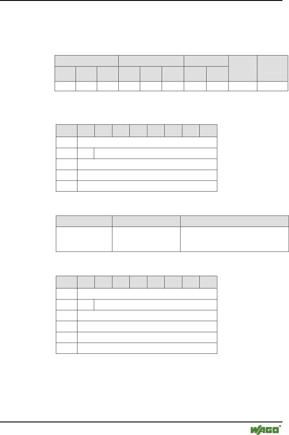
Appendix • 109
Mailbox Command References
WAGO-I/O-SYSTEM 750
I/O Modules
6.3.2.3 End a Block Download or Upload (DLD_END, 0x03)
With call up, the uploading and downloading of a block is ended.
Conditions
Mailbox size Operating mode/profile Device role
6 12 18 Config. Real-
time Ad hoc Master Slave
Save
config. Restart
● ● ● ● - - ● ● ●* ●*
* A restart is only conducted after successful writing operations in the configuration mode.
Request
Byte 27 26 25 24 23 22 21 20
0 MBX_DLD_END
1 T -
2 MBX_CHECKSUM (LSB)
3 MBX_CHECKSUM
4 MBX_CHECKSUM (MSB)
Arguments
Parameter Value Description
MBX_CHECKSUM The value is determined
by bytewise addition of
the transmitted values.
Checksum of the block:
The content is dependent on the transmit-
ted data bytes.
Response
Byte 27 26 25 24 23 22 21 20
0 MBX_DLD_END
1 T MBX_RESULT
2 DLD_RESULT
3 MBX_CHECKSUM (LSB)
4 MBX_CHECKSUM
5 MBX_CHECKSUM (MSB)

110 • Appendix
Mailbox Command References
WAGO-I/O-SYSTEM 750
I/O Modules
Return values
Parameter Value Description
MBX_CMD_OK Transfer successful MBX_RESULT
MBX_CMD_GENERAL_ERROR An error has occurred. More de-
tailed information in
DLD_RESULT
DLD_OK (0x00) No error occurred
DLD_ERROR_DOWNLOAD_NOT
_STARTED (0x01)
There is no active transfer.
The command is invalid.
DLD_ERROR_CHECKSUM (0x32) Checksum error
DLD_ERROR_UNDERFLOW
(0x33)
Underrun, too little data.
DLD_RESULT
DLD_ERROR_DATASET_
CORRUPT (0x38)
Configuration mode:
Written block in the "Extended
Register" is defective
DLD_
CHECKSUM
Checksum for the upload calculated
in the Bluetooth® subsystem
(Bluetooth® subsystem for SPS)
Checksum
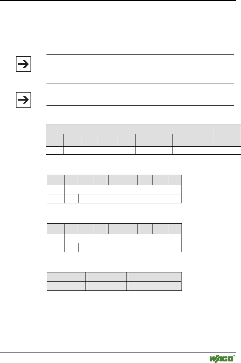
Appendix • 111
Mailbox Command References
WAGO-I/O-SYSTEM 750
I/O Modules
6.3.3 Maintenance and Firmware
6.3.3.1 Warm Start of the Bluetooth® Subsystem (RebootHost, 0x10)
With call up, the Bluetooth® subsystem is restarted. All wireless connections
are broken off.
Note
This command causes a restart with no prior saving of the configuration.
Therefore, changes made since the last time the configuration was saved are
lost.
Note
If "RebootHost" is called up, all wireless connections are broken off.
Conditions
Mailbox size Operating mode/profile Device role
6 12 18 Config. Real-
time Ad hoc Master Slave
Save
config. Restart
● ● ● ● ● ● ● ● - ●
Request
Byte 27 26 25 24 23 22 21 20
0 MBX_REBOOTHOST
1 T -
Response
Byte 27 26 25 24 23 22 21 20
0 MBX_REBOOTHOST
1 T MBX_RESULT
Return values
Parameter Value Description
- - -
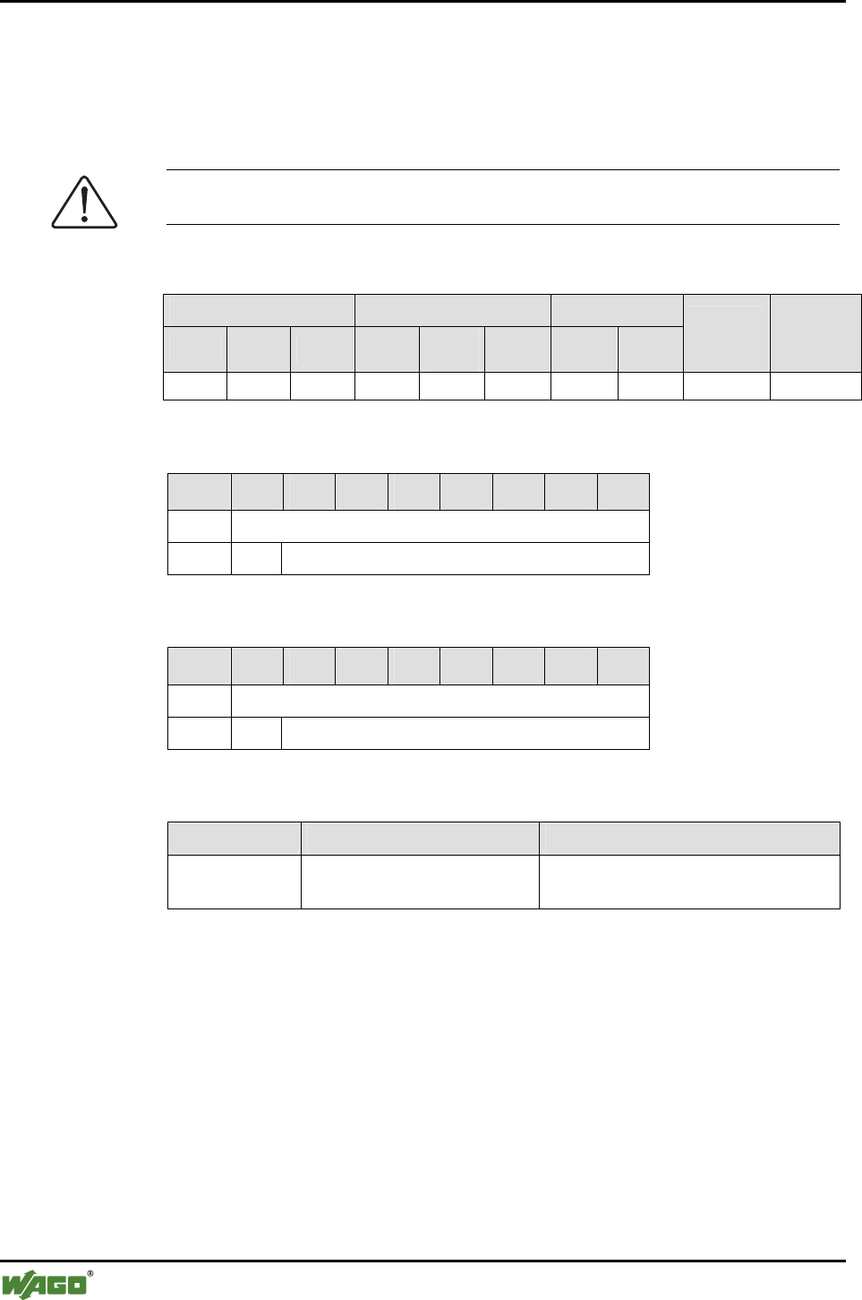
112 • Appendix
Mailbox Command References
WAGO-I/O-SYSTEM 750
I/O Modules
6.3.3.2 Saving the Configuration with Subsequent Warm Start (FlashRebootHost,
0x11)
With call up, the current configuration of the Bluetooth® subsystem is written
in the flash memory. Then the Bluetooth® subsystem is restarted.
Note
If "RebootHost" is called up, all wireless connections are broken off.
Conditions
Mailbox size Operating mode/profile Device role
6 12 18 Config. Real-
time Ad hoc Master Slave
Save
config. Restart
● ● ● ● ● ● ● ● - ●
Request
Byte 27 26 25 24 23 22 21 20
0 MBX_FLASHREBOOTHOST
1 T -
Response
Byte 27 26 25 24 23 22 21 20
0 MBX_FLASHREBOOTHOST
1 T MBX_RESULT
Return values
Parameter Value Description
MBX_RESULT MBX_CMD_DENIED_BUSY A block-oriented command is active in
the execution
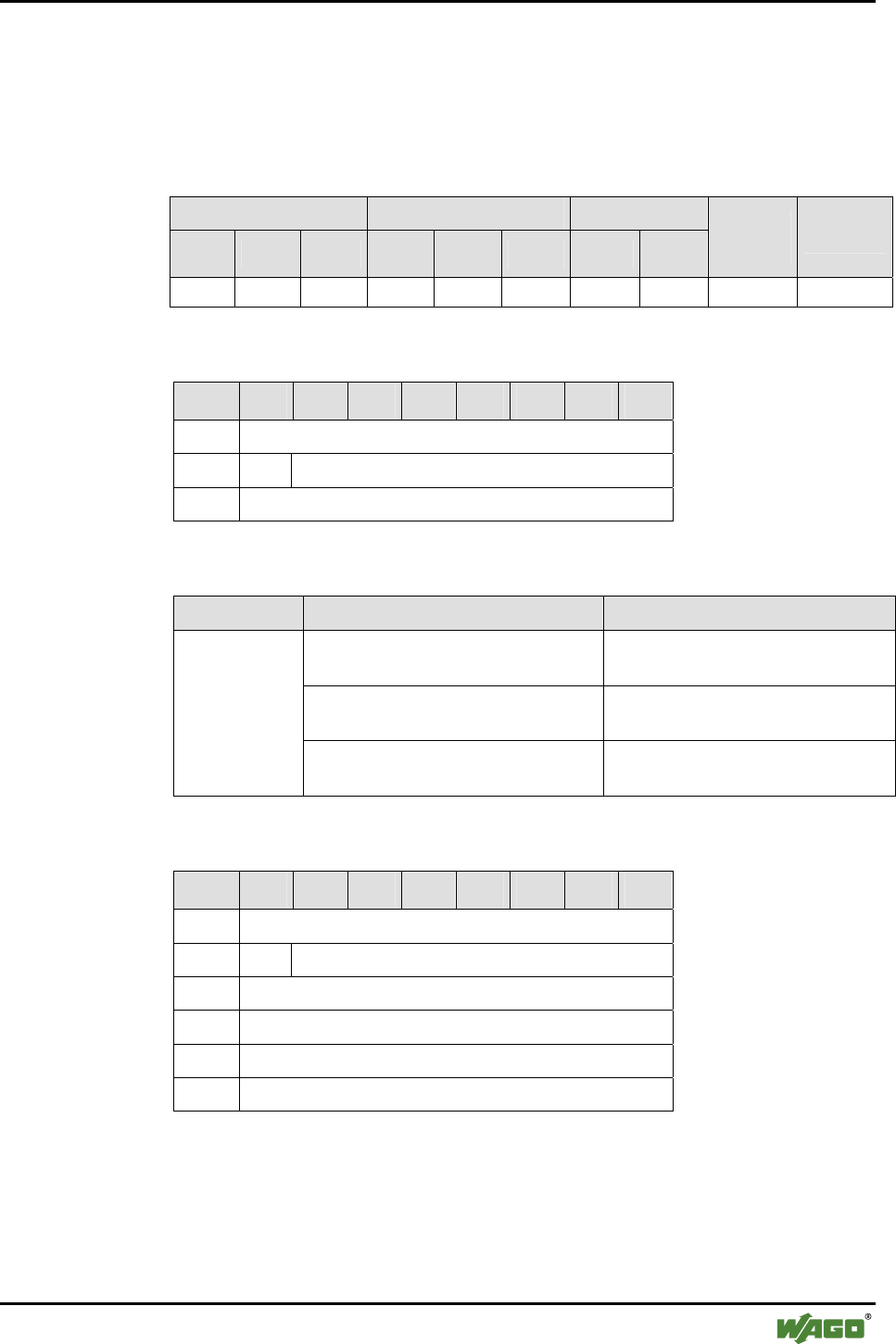
Appendix • 113
Mailbox Command References
WAGO-I/O-SYSTEM 750
I/O Modules
6.3.3.3 Read Host Firmware Version (GetHostFwVersion, 0x12)
With call up, version information is read by firmware components of the Blue-
tooth® subsystem.
Conditions
Mailbox size Operating mode/profile Device role
6 12 18 Config. Real-
time Ad hoc Master Slave
Save
config. Restart
● ● ● ● - - ● ● - -
Request
Byte 27 26 25 24 23 22 21 20
0 MBX_GETHOSTFWVERSION
1 T -
2 MBX_FW_ID
Arguments
Parameter Value Description
MBX_CM_GETHOSTFWVERSION
_BOOTLOADER (0x01)
Read version of boot loader
MBX_CM_GETHOSTFWVERSION
_FIRMWARE (0x02)
Read version of Bluetooth® subsys-
tem firmware
MBX_FW_ID
MBX_CM_GETHOSTFWVERSION
_CONFIGURATION (0x03)
Read version of configuration
Response
Byte 27 26 25 24 23 22 21 20
0 MBX_GETHOSTFWVERSION
1 T MBX_RESULT
2 MBX_FW_ID
3 MBX_VN_MAJOR
4 MBX_VN_MINOR
5 MBX_VN_RELEASE

114 • Appendix
Mailbox Command References
WAGO-I/O-SYSTEM 750
I/O Modules
Return values
Parameter Value Description
MBX_RESULT MBX_CMD_INVALID_ARG Invalid value for
MBX_FW_ID
MBX_CM_GETHOSTFWVERSION
_BOOTLOADER (0x01)
Version of boot loader
MBX_CM_GETHOSTFWVERSION
_FIRMWARE (0x02)
Version of Bluetooth®
subsystem
MBX_FW_ID
MBX_CM_GETHOSTFWVERSION
_CONFIGURATION (0x03)
Version of configura-
tion
MBX_VN_MAJOR [0...255] Main version number
MBX_VN_MINOR [0...255] Subversion number
MBX_VN_RELEASE [0...255] Release of subversion
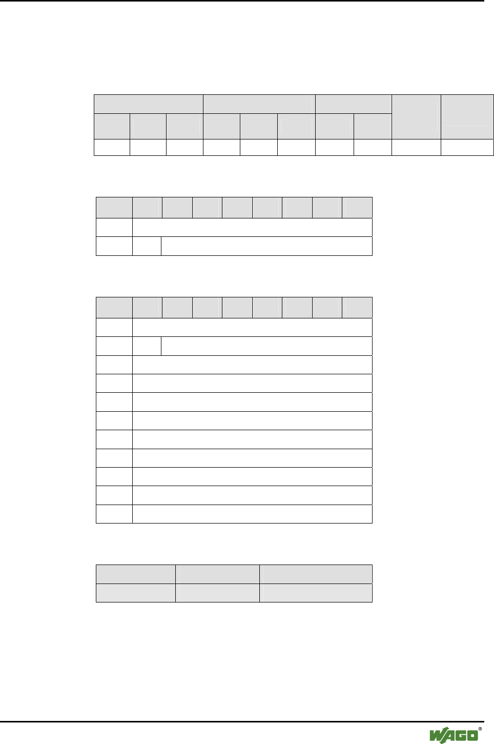
Appendix • 115
Mailbox Command References
WAGO-I/O-SYSTEM 750
I/O Modules
6.3.3.4 Read Version of Baseband Controller Firmware (GetBbFwVersion, 0x13)
With call up, the version information for the baseband controller is read.
Conditions
Mailbox size Operating mode/profile Device role
6 12 18 Config. Real-
time Ad hoc Master Slave
Save
config. Restart
(●) ● ● ● - - ● ● - -
Request
Byte 27 26 25 24 23 22 21 20
0 MBX_GETBBFWVERSION
1 T -
Response
Byte 27 26 25 24 23 22 21 20
0 MBX_GETBBFWVERSION
1 T MBX_RESULT
2 Fw_Status
3 Fw_HCI_Version
4 Fw_HCI_Revision (High)
5 Fw_HCI_Revision (Low)
6 Fw_LMP_Version
7 Fw_Manufacturer_Name (High)
8 Fw_Manufacturer_Name (Low)
9 Fw_LMP_Subversion (High)
10 Fw_LMP_Subversion (Low)
Return values
Parameter Value Description
- - -
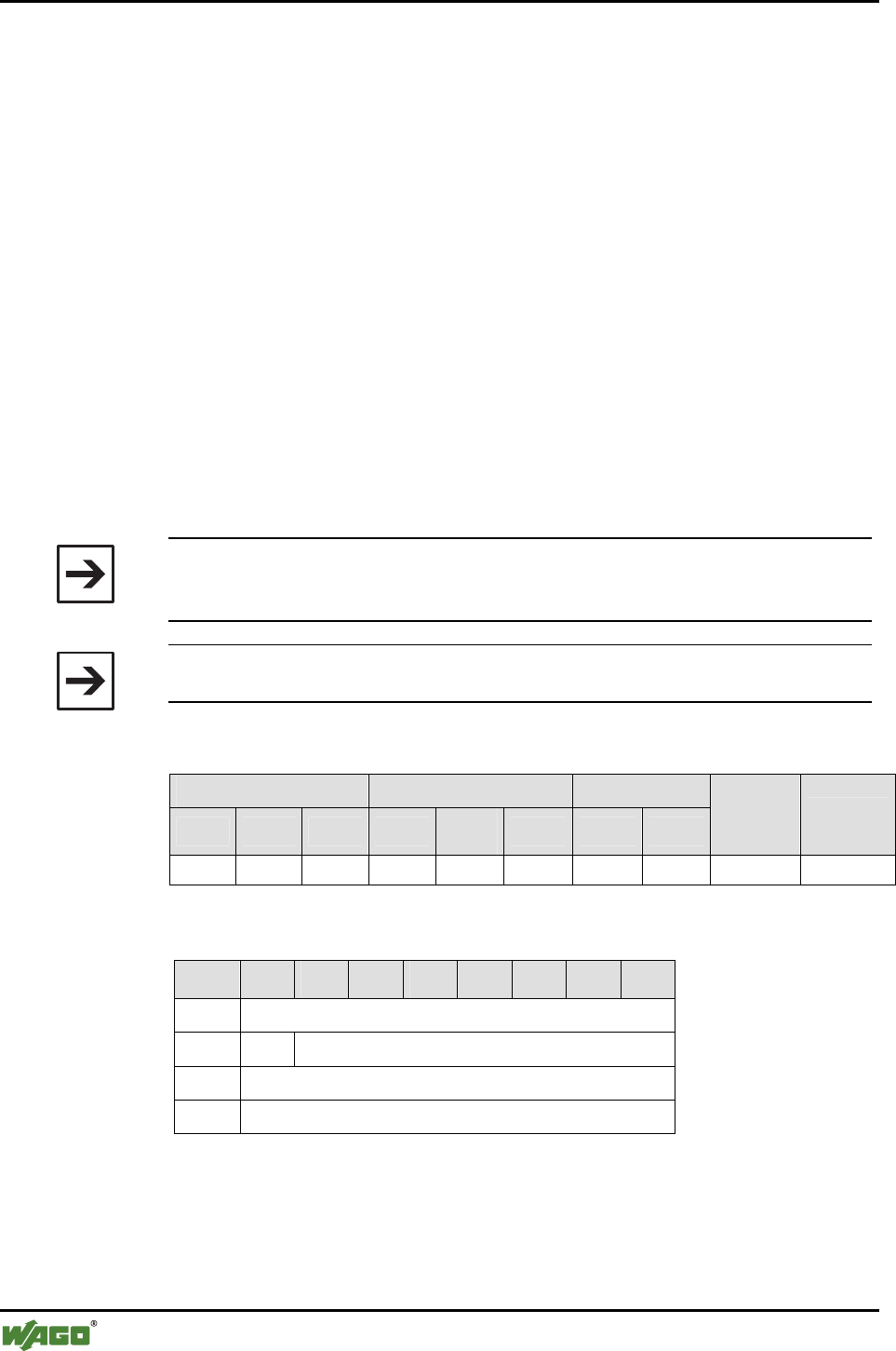
116 • Appendix
Mailbox Command References
WAGO-I/O-SYSTEM 750
I/O Modules
6.3.4 Process Image
6.3.4.1 Determine the Size of a Slot for Data Transfer in the Master Process Image
(SetRemotePiSize, 0x32)
With this command, the process image of a remote bus module is limited to n
bytes within the master process image. Therefore, the total of all slave process
images in the master may not be larger than the set master process image - 2.
This is because two bytes of the total size are necessary for the control/status
byte and a reserved byte. The size of the master process image can be queried
and configured over the parameter channel. It is contained in the LSB by pa-
rameter 0.
By downsizing the available process image, the sum of the configured cutoffs
may exceed the size of the master process image. In this case, the initial con-
figuration is already invalid. In such a case, the configuration is executed, but
the error value MBX_CMD_INVALID_CONFIGURATION is displayed. If
the initial configuration is correct, a command that leads to an invalid configu-
ration is acknowledged and rejected with an error.
Note
The process image mapping can also be configured in the slave mode, but
does not have any effect until it is changed to the master mode.
Note
Slots 1 and 13 must be given as parameters in the area 0 through 12.
Conditions
Mailbox size Operating mode/profile Device role
6 12 18 Config. Real-
time Ad hoc Master Slave
Save
config. Restart
● ● ● ● - - ● ● ● -
Request
Byte 27 26 25 24 23 22 21 20
0 MBX_SETREMOTEPISIZE
1 T -
2 MBX_TARGET_TABLE_AND_INDEX
3 CUTOFF_N_BYTES
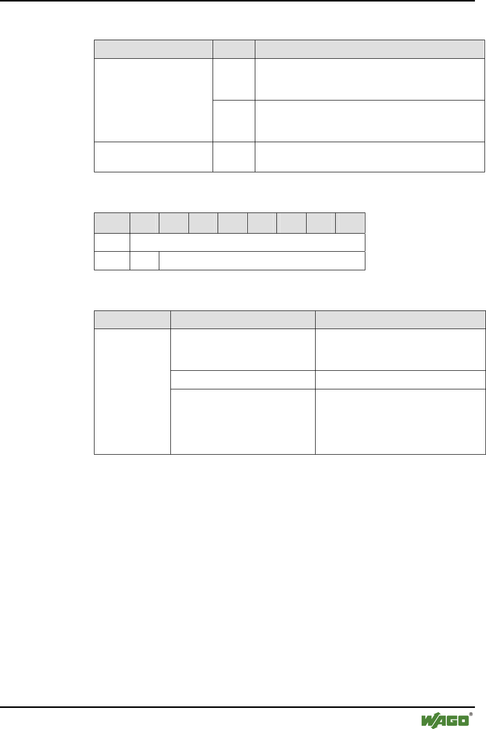
Appendix • 117
Mailbox Command References
WAGO-I/O-SYSTEM 750
I/O Modules
Arguments
Parameter Value Description
Bit 0…3 Table Index
Index 0...6 for WAGO devices of slots 1...7
Index 0...5 for external devices of slots 8...12
MBX_TARGET_TABLE_
AND_INDEX
Bit 4…7 Target table
"2" for WAGO_DEVICE (slots 1...7)
"1" for EXTERNAL_DEVICE (slots 8...12)
CUTOFF_N_BYTES [0...46] Number of bytes after which the slave process image
is cut off. The redundant bytes will be lost.
Response
Byte 27 26 25 24 23 22 21 20
0 MBX_SETREMOTEPISIZE
1 T MBX_RESULT
Return values
Parameter Value Description
MBX_CMD_INVALID_
CONFIGURATION
Before and after the command, the sum
of all CUTOFF_N_BYTES is larger
than the available master process image.
MBX_CMD_INVALID_ARG No valid target table has been chosen.
MBX_
RESULT
MBX_CMD_OUT_OF_RANGE With the given value, the sum of all
CUTOFF_N_BYTES would exceed the
limit of the available master process
image or the indicated index is too
large.
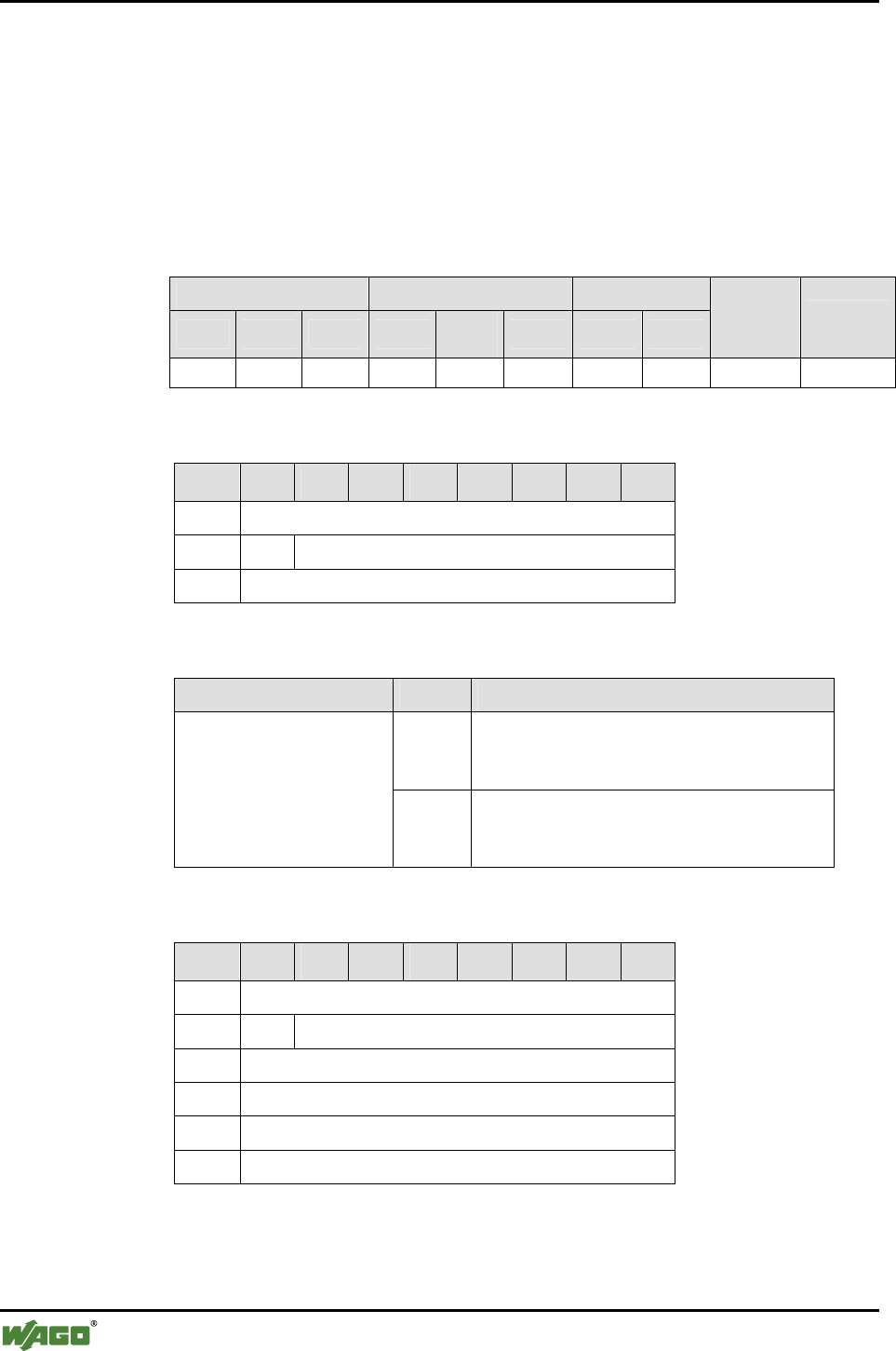
118 • Appendix
Mailbox Command References
WAGO-I/O-SYSTEM 750
I/O Modules
6.3.4.2 Query the Remote Process Image Parameters within the Master Process
Image (GetRemotePiMapping, 0x33)
With this command, the settings for a slot in the local process image are que-
ried. There are 13 slots available. Slots 1 through 7 are occupied by the fields
of the WAGO device table and slots 8 through 13 by the fields of the table of
external devices.
Conditions
Mailbox size Operating mode/profile Device role
6 12 18 Config. Real-
time Ad hoc Master Slave
Save
config. Restart
● ● ● ● ● ● ● ● - -
Request
Byte 27 26 25 24 23 22 21 20
0 MBX_GETREMOTEPIMAPPING
1 T -
2 MBX_TARGET_TABLE_AND_NDEX
Arguments
Parameter Value Description
Bit 0…3 Table Index
Index 0...6 for WAGO devices of slots 1...7
Index 0...5 for external devices of slots 8...12
MBX_TARGET_TABLE_
AND_INDEX
Bit 4…7 Target table
"2" for WAGO_DEVICE (slots 1...7)
"1" for EXTERNAL_DEVICE (slots 8...12)
Response
Byte 27 26 25 24 23 22 21 20
0 MBX_GETREMOTEPIMAPPING
1 T MBX_RESULT
2 MBX_DEVICE_INDEX
3 OFFSET
4 - reserved -
5 CUTOFF_N_BYTES

Appendix • 119
Mailbox Command References
WAGO-I/O-SYSTEM 750
I/O Modules
Return values
Parameter Value Description
MBX_CMD_INVALID
_ARG
No valid target table has been chosen. MBX_RESULT
MBX_CMD_OUT_OF
_RANGE
The indicated index is too large.
MBX_DEVICE_INDEX [0...12] Slot of the slave process image within
the master process image
OFFSET [0...45] Position of the first byte of the slot in
the local process image relative to the
C/S byte. Slot 1 always has an offset
of 0.
CUTOFF_N_BYTES Number Number of bytes after which the slave
process image is cut off.
- reserved - 0x00 Reserved for later use.
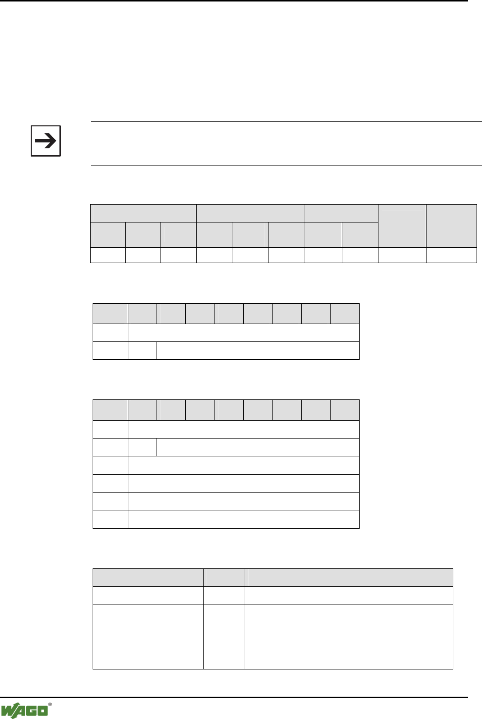
120 • Appendix
Mailbox Command References
WAGO-I/O-SYSTEM 750
I/O Modules
6.3.5 Device Configuration
6.3.5.1 Read the Local Device Name(GetLocalDeviceName, 0x40)
The characters of the Bluetooth® name of the local bus module are read by this
query. The number of characters returned depends on the configured name,
but has a maximum of (mailbox size - 3).
Note
The complete device name can be a maximum of 15 characters. The complete
device name can be queried with DLD commands regardless of the mailbox size.
Conditions
Mailbox size Operating mode/profile Device role
6 12 18 Config. Real-
time Ad hoc Master Slave
Save
config. Restart
(●) (●) ● ● - - ● ● - -
Request
Byte 27 26 25 24 23 22 21 20
0 MBX_GETLOCALDEVICENAME
1 T -
Response
Byte 27 26 25 24 23 22 21 20
0 MBX_GETLOCALDEVICENAME
1 T MBX_RESULT
2 MBX_NAME_LENGTH
3 CHAR1
... ...
17 CHAR15
Return values
Parameter Value Description
MBX_NAME_LENGTH [0...255] Number of characters of the complete name
CHARn [0...255] Characters of the device name in ASCII code
Example: "ABC"
A = CHAR1 = 0x41
B = CHAR2 = 0x42
C = CHAR3 = 0x43
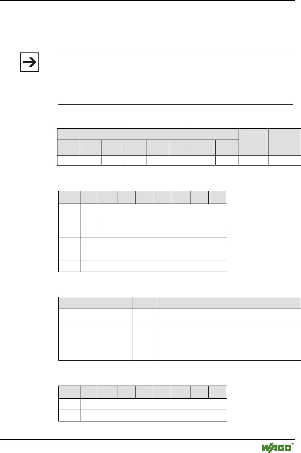
Appendix • 121
Mailbox Command References
WAGO-I/O-SYSTEM 750
I/O Modules
6.3.5.2 Write the Local Device Name (SetLocalDeviceName, 0x41)
With this command, the Bluetooth® name of the local bus module is set. The
normal set of ASCII characters is available.
Note
The use of special characters (e.g. word wraps) is possible but should be
avoided.
The complete device name can be a maximum of 15 characters.
The complete device name can be read and written with DLD commands
regardless of the mailbox size.
Conditions
Mailbox size Operating mode/profile Device role
6 12 18 Config. Real-
time Ad hoc Master Slave
Save
config. Restart
(●) (●) ● ● - - ● ● - -
Request
Byte 27 26 25 24 23 22 21 20
0 MBX_SETLOCALDEVICENAME
1 T -
2 MBX_NAME_LENGTH
3 CHAR1
... ...
17 CHAR15
Arguments
Parameter Value Description
MBX_NAME_LENGTH [1...15] Number of the transferred characters of the name
CHARn Characters of the device name in ASCII code
Example: "ABC"
A = CHAR1 = 0x41
B = CHAR2 = 0x42
C = CHAR3 = 0x43
Response
Byte 27 26 25 24 23 22 21 20
0 MBX_SETLOCALDEVICENAME
1 T MBX_RESULT

122 • Appendix
Mailbox Command References
WAGO-I/O-SYSTEM 750
I/O Modules
Return values
Parameter Value Description
MBX_RESULT MBX_CMD_OUT_OF_RANGE MBX_NAME_LENGTH is equal to 0
or greater than (mailbox size - 3)
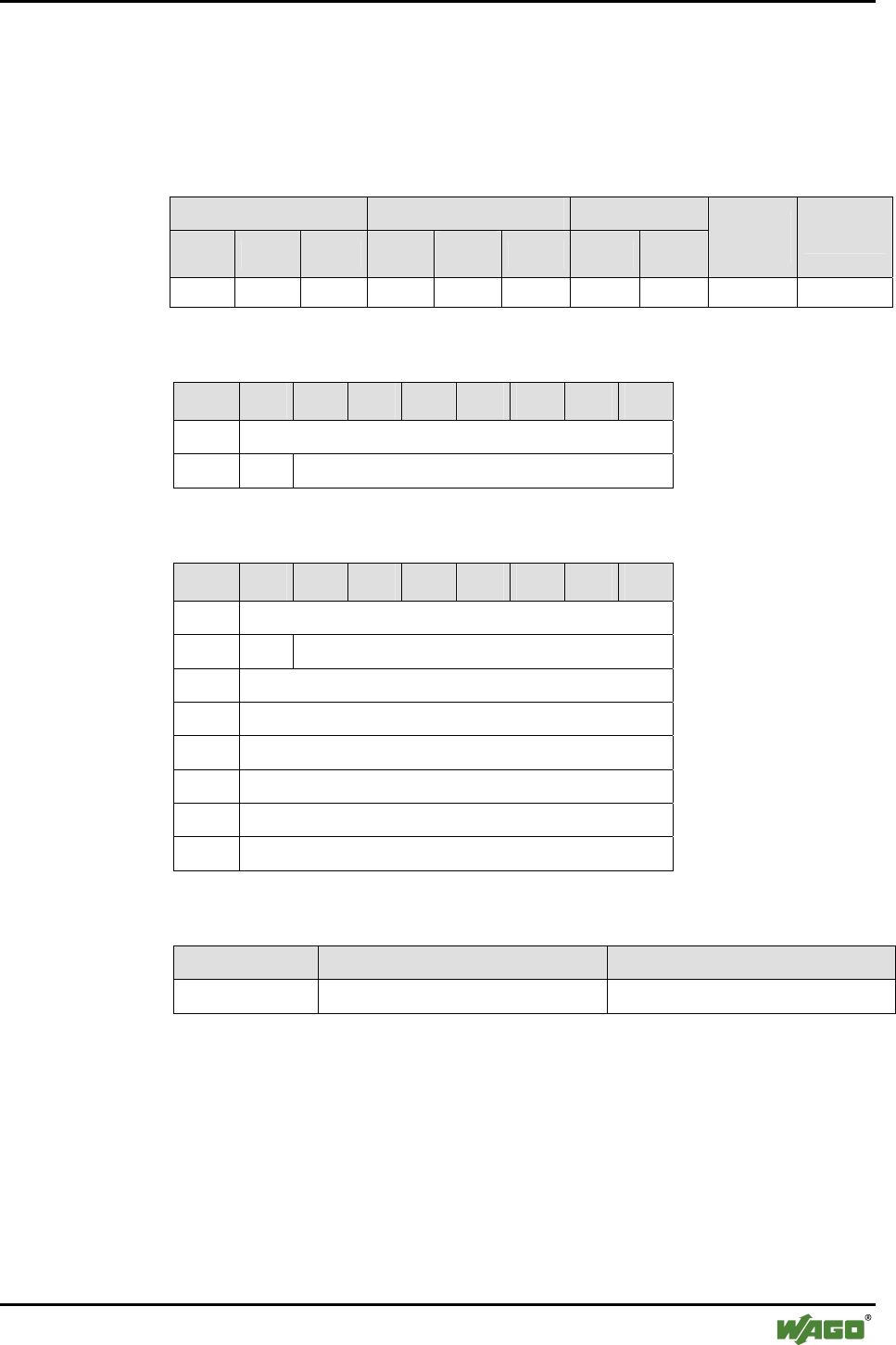
Appendix • 123
Mailbox Command References
WAGO-I/O-SYSTEM 750
I/O Modules
6.3.5.3 Read Local MAC ID (GetLocalMacID, 0x42)
With this command, the Bluetooth® MAC-ID (48-bit address) of the local
Bluetooth® module is read.
Conditions
Mailbox size Operating mode/profile Device role
6 12 18 Config. Real-
time Ad hoc Master Slave
Save
config. Restart
- ● ● ● - - ● ● - -
Request
Byte 27 26 25 24 23 22 21 20
0 MBX_GETLOCALMACID
1 T -
Response
Byte 27 26 25 24 23 22 21 20
0 MBX_GETLOCALMACID
1 T MBX_RESULT
2 MAC-ID byte 0 (LSB)
3 MAC-ID byte 1
4 MAC-ID byte 2
5 MAC-ID byte 3
6 MAC-ID byte 4
7 MAC-ID byte 5 (MSB)
Return values
Parameter Value Description
MAC ID byte n [0…255] The bytes of the MAC address
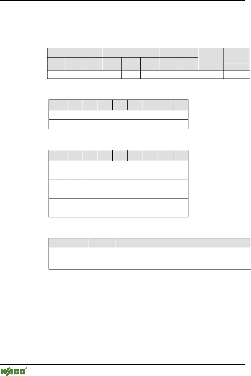
124 • Appendix
Mailbox Command References
WAGO-I/O-SYSTEM 750
I/O Modules
6.3.5.4 Read Local IP Address (GetLocalIPAddress, 0x43)
With this command, the IP address (IPv4) of the local bus module is read.
Conditions
Mailbox size Operating mode/profile Device role
6 12 18 Config. Real-
time Ad hoc Master Slave
Save
config. Restart
● ● ● ● - - ● ● - -
Request
Byte 27 26 25 24 23 22 21 20
0 MBX_GETLOCALIPADDRESS
1 T -
Response
Byte 27 26 25 24 23 22 21 20
0 MBX_GETLOCALIPADDRESS
1 T MBX_RESULT
2 Ip-Addr_1 (LSB)
3 Ip-Addr_2
4 Ip-Addr_3
5 Ip-Addr_4 (LSB)
Return values
Parameter Value Description
IP-Addr_1
…
IP-Addr_4
[0...255] The bytes of the IPv4 address in the form
IP-Addr_4.IP-Addr_3.IP-Addr_2.IPAddr_1
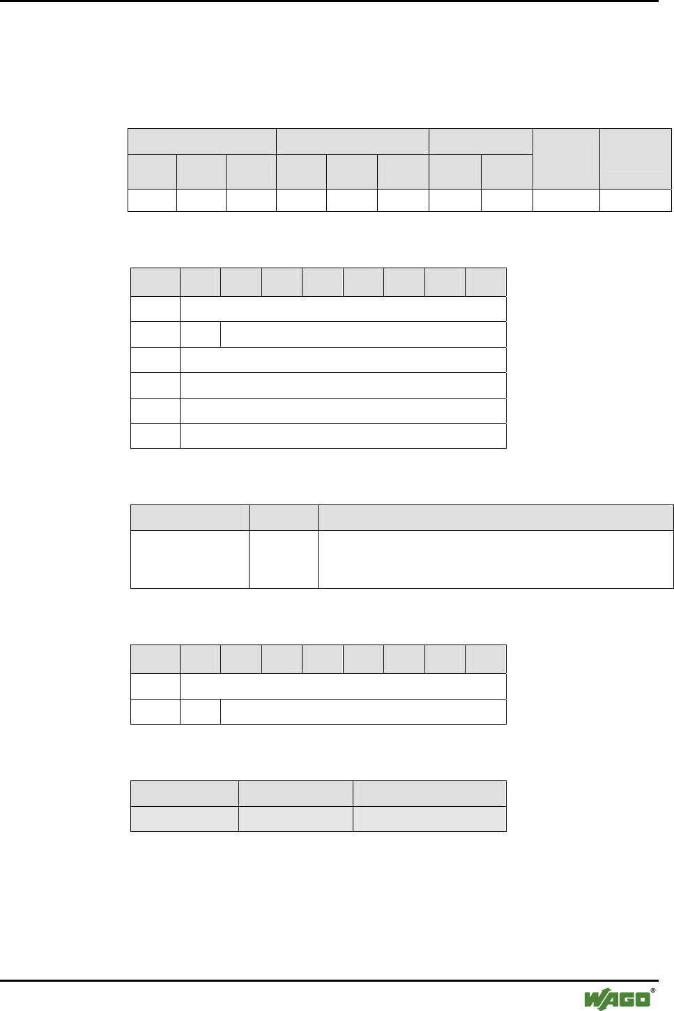
Appendix • 125
Mailbox Command References
WAGO-I/O-SYSTEM 750
I/O Modules
6.3.5.5 Set Local IP Address (SetLocalIPAddress, 0x44)
With this command, the IP address (IPv4) of the local bus module is read.
Conditions
Mailbox size Operating mode/profile Device role
6 12 18 Config. Real-
time Ad hoc Master Slave
Save
config. Restart
● ● ● ● - - ● ● ● -
Request
Byte 27 26 25 24 23 22 21 20
0 MBX_SETLOCALIPADDRESS
1 T -
2 Ip-Addr_1 (LSB)
3 Ip-Addr_2
4 Ip-Addr_3
5 Ip-Addr_4 (MSB)
Arguments
Parameter Value Description
IP-Addr_1
...
IP_Addr_4
[0...255] The bytes of the IPv4 address
Response
Byte 27 26 25 24 23 22 21 20
0 MBX_SETLOCALIPADDRESS
1 T MBX_RESULT
Return values
Parameter Value Description
- - -

126 • Appendix
Mailbox Command References
WAGO-I/O-SYSTEM 750
I/O Modules
6.3.5.6 Read Local Subnet Mask (GetLocalSubnetMask, 0x45)
With this command, the subnet mask (IPv4) of the local bus module is read.
Conditions
Mailbox size Operating mode/profile Device role
6 12 18 Config. Real-
time Ad hoc Master Slave
Save
config. Restart
● ● ● ● - - ● ● - -
Request
Byte 27 26 25 24 23 22 21 20
0 MBX_GETLOCALSUBNETMASK
1 T -
Response
Byte 27 26 25 24 23 22 21 20
0 MBX_GETLOCALIPSUBCLASS
1 T MBX_RESULT
2 Subnet Mask -Addr_1 (LSB)
3 Subnet Mask -Addr_2
4 Subnet Mask -Addr_3
5 Subnet Mask -Addr_4 (MSB)
Return values
Parameter Value Description
Subnet-Mask –Addr n [0...255] The bytes of the subnet mask
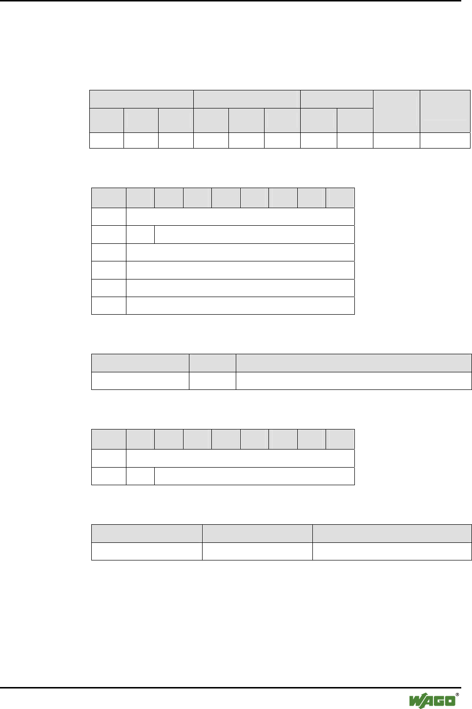
Appendix • 127
Mailbox Command References
WAGO-I/O-SYSTEM 750
I/O Modules
6.3.5.7 Set Local Subnet Mask (SetLocalSubnetMask, 0x46)
With this command, the subnet mask (IPv4) of the local bus module is written.
Conditions
Mailbox size Operating mode/profile Device role
6 12 18 Config. Real-
time Ad hoc Master Slave
Save
config. Restart
● ● ● ● - - ● ● ● -
Request
Byte 27 26 25 24 23 22 21 20
0 MBX_SETLOCALSUBNETMASK
1 T -
2 Subnet-Mask -Addr_1 (LSB)
3 Subnet-Mask -Addr_2
4 Subnet-Mask -Addr_3
5 Subnet-Mask -Addr_4 (MSB)
Arguments
Parameter Value Description
Subnet Mask-Addr_n [0...255] The bytes of the IPv4 subnet mask
Response
Byte 27 26 25 24 23 22 21 20
0 MBX_SETLOCALIPADDRESS
1 T MBX_RESULT
Return values
Parameter Value Description
MBX_RESULT MBX_CMD_OK No error occurred

128 • Appendix
Mailbox Command References
WAGO-I/O-SYSTEM 750
I/O Modules
6.3.5.8 Read Local WAGO Device Class (GetLocalDeviceClass, 0x47)
With this command, the WAGO device class of the local bus module is read.
Types of modules can be differentiated using the device class. A grouping of
modules according to their tasks is also possible. When searching for modules
with a certain device class, an inquiry using the Bluetooth® Class-of-Device
can help. The WAGO device classes have only an indirect relation to the Blue-
tooth® Class-of-Device.
The connection between the WAGO device classes and the Bluetooth® Class-
of-Device is explained in Section 2.1.1.6.1.
Conditions
Mailbox size Operating mode/profile Device role
6 12 18 Config. Real-
time Ad hoc Master Slave
Save
config. Restart
● ● ● ● - - ● ● - -
Request
Byte 27 26 25 24 23 22 21 20
0 MBX_GETLOCALDEVICECLASS
1 T -
Response
Byte 27 26 25 24 23 22 21 20
0 MBX_GETLOCALDEVICECLASS
1 T MBX_RESULT
2 WAGO_Deviceclass
3 WAGO_SubDeviceclass
Return values
Parameter Value Description
WAGO_Deviceclass [0...7] Device class according to Section 2.1.1.6.1
WAGO_SubDeviceclass [0...7] Subdevice class according to Section 2.1.1.6.1
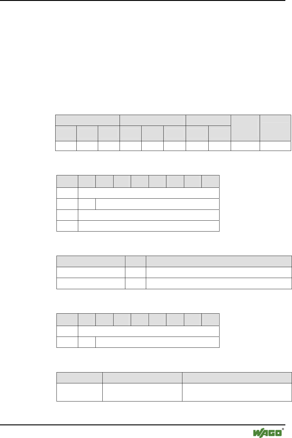
Appendix • 129
Mailbox Command References
WAGO-I/O-SYSTEM 750
I/O Modules
6.3.5.9 Write Local Device Class (SetLocalDeviceClass, 0x48)
With this command, the WAGO device class of the local bus module is writ-
ten. Types of modules can be differentiated using the device class. A grouping
of modules according to their tasks is also possible. When searching for mod-
ules with a certain device class, an inquiry using the Bluetooth® Class-of-
Device can help. The device classes have only an indirect relation to the Blue-
tooth® Class-of-Device.
The connection between the WAGO device classes and the Bluetooth® Class-
of-Device is explained in Section 2.1.1.6.1.
Conditions
Mailbox size Operating mode/profile Device role
6 12 18 Config. Real-
time Ad hoc Master Slave
Save
config. Restart
● ● ● ● - - ● ● ● -
Request
Byte 27 26 25 24 23 22 21 20
0 MBX_SETLOCALDEVICECLASS
1 T -
2 WAGO_Deviceclass
3 WAGO_SubDeviceclass
Arguments
Parameter Value Description
WAGO_Deviceclass [0...7] Device class according to Section 2.1.1.6.1
WAGO_SubDeviceclass [0...7] Subdevice class according to Section 2.1.1.6.1
Response
Byte 27 26 25 24 23 22 21 20
0 MBX_SETLOCALDEVICECLASS
1 T MBX_RESULT
Return values
Parameter Value Description
MBX_RESULT MBX_CMD_INVALID_ARG Invalid value for WAGO_deviceclass or
WAGO_SubDeviceclass
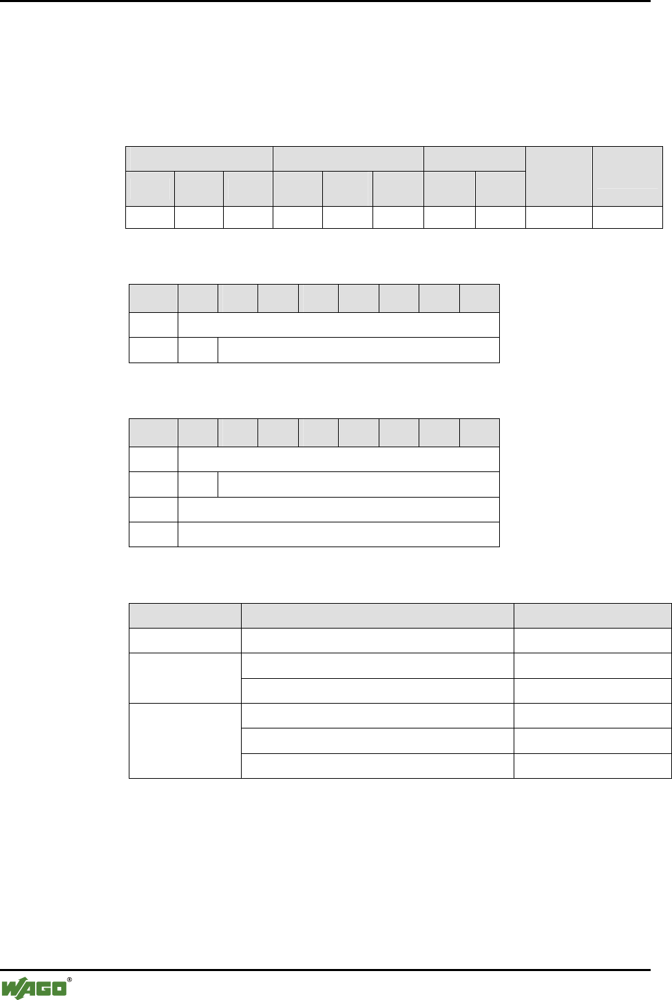
130 • Appendix
Mailbox Command References
WAGO-I/O-SYSTEM 750
I/O Modules
6.3.5.10 Read Local Operation Mode (GetLocalOperationMode, 0x49)
With this command, the operating mode and communication profile of the lo-
cal Bluetooth® module are read.
Conditions
Mailbox size Operating mode/profile Device role
6 12 18 Config. Real-
time Ad hoc Master Slave
Save
config. Restart
● ● ● ● ● ● ● ● - -
Request
Byte 27 26 25 24 23 22 21 20
0 MBX_GETLOCALOPERATIONMODE
1 T -
Response
Byte 27 26 25 24 23 22 21 20
0 MBX_GETLOCALOPERATIONMODE
1 T MBX_RESULT
2 MBX_OPMODE_ID
3 MBX_COMMROFILE_ID
Return values
Parameter Value Description
MBX_RESULT MBX_CMD_INVALID_ARG Parameter value(s) invalid
MBX_CM_OPMODE_CONF (0x01) Configuration mode MBX_OPMODE
_ID MBX_CM_OPMODE_COMM (0x02) Communication mode
MBX_CM_OPPROFILE_REALTIME (0x01) Real-time profile
MBX_CM_OPPROFILE_CONFIG (0x02) Configuration profile
MBX_
COMMROFILE
_ID
MBX_CM_OPPROFILE_ADHOC (0x03) Ad hoc profile
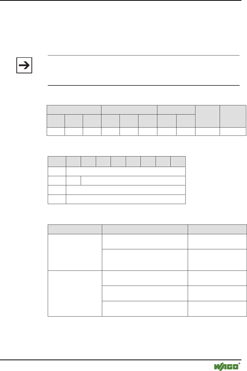
Appendix • 131
Mailbox Command References
WAGO-I/O-SYSTEM 750
I/O Modules
6.3.5.11 Set Local Operation Mode (SetLocalOperationMode, 0x4A)
With call up, the operating mode and communication profile of the Bluetooth®
subsystem are set. The call up is followed by a warm start of the Bluetooth®
bus module in the chosen operating mode, saving any changes made to the
configuration.
Note
If an operating mode is chosen that has already been accepted by the module,
then the command is acknowledged with MBX_CMD_OK, but there is no
restart of the module. No changes made to the configuration are saved.
Conditions
Mailbox size Operating mode/profile Device role
6 12 18 Config. Real-
time Ad hoc Master Slave
Save
config. Restart
● ● ● ● ● ● ● ● ● ●
Request
Byte 27 26 25 24 23 22 21 20
0 MBX_SETLOCALOPERATIONMODE
1 T -
2 MBX_OPMODE_ID
3 MBX_COMMROFILE_ID
Arguments
Parameter Value Description
MBX_CM_OPMODE_CONF
(0x01)
Configuration mode (with
configuration profile only)
MBX_OPMODE_ID
MBX_CM_OPMODE_COMM
(0x02)
Communication mode
(with real-time profile or
ad hoc profile only)
MBX_CM_OPPROFILE_REALTIME
(0x01)
Real-time profile
MBX_CM_OPPROFILE_CONFIG
(0x02)
Configuration profile
MBX_COMMROFILE
_ID
MBX_CM_OPPROFILE_ADHOC
(0x03)
Ad hoc profile

132 • Appendix
Mailbox Command References
WAGO-I/O-SYSTEM 750
I/O Modules
Response
Byte 27 26 25 24 23 22 21 20
0 MBX_SETLOCALOPERATIONMODE
1 T MBX_RESULT
Return values
Parameter Value Description
MBX_RESULT MBX_CMD_INVALID_ARG An invalid value for one of the argu-
ments or an invalid combination was
chosen.
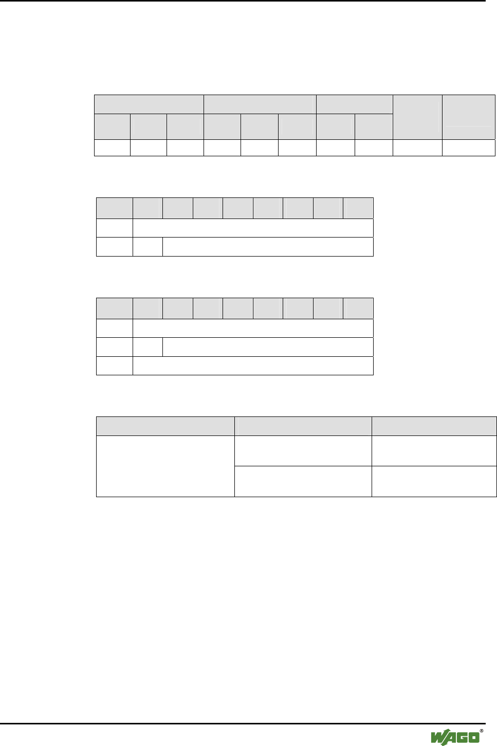
Appendix • 133
Mailbox Command References
WAGO-I/O-SYSTEM 750
I/O Modules
6.3.5.12 Read Local Encryption Mode (GetLocalEncryptionMode, 0x4D)
With call up, the encryption mode for the wireless transmission is read.
Conditions
Mailbox size Operating mode/profile Device role
6 12 18 Config. Real-
time Ad hoc Master Slave
Save
config. Restart
● ● ● ● - - ● ● - -
Request
Byte 27 26 25 24 23 22 21 20
0 MBX_GETLOCALENCRYPTIONMODE
1 T -
Response
Byte 27 26 25 24 23 22 21 20
0 MBX_GETLOCALENCRYPTIONMODE
1 T MBX_RESULT
2 MBX_ENCRYPTION_MODE
Return values
Parameter Value Description
MBX_ENCRYPT_ENABLE
(0x01)
Encryption is active
(standard)
MBX_ENCRYPTION_MODE
MBX_ENCRYPT_DISABLE
(0x00)
Encryption is not active
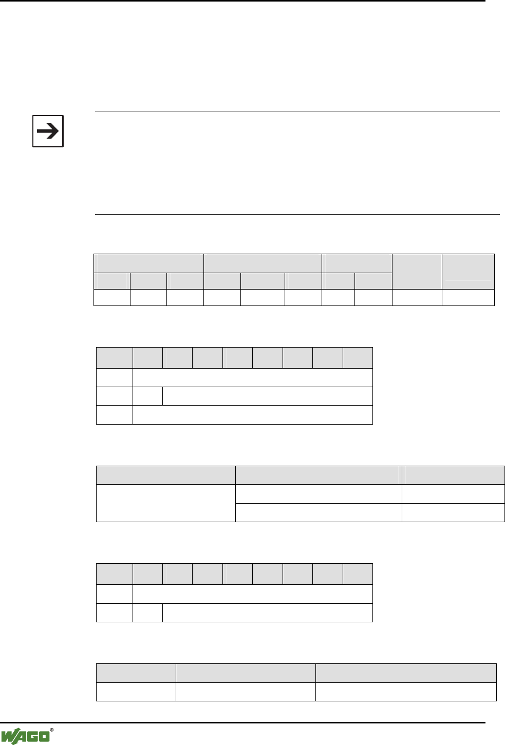
134 • Appendix
Mailbox Command References
WAGO-I/O-SYSTEM 750
I/O Modules
6.3.5.13 Set Local Encryption Mode (SetLocalEncryptionMode, 0x4E)
With this command, the encryption of the Bluetooth® data transmission is ac-
tivated or deactivated. This setting can be done independently of the device
role, but only affects the master. If encryption is activated, devices that do not
use encryption cannot connect.
Note
Encryption can be activated without activating an authentication. The actual en-
cryption of the data takes place after an authentication.
The security of the encryption is linked to the quality of the password.
Connections between devices can only be established if the settings for encryp-
tion, authentication and password are synchronized. This can be achieved by hav-
ing identical settings for the devices to be connected.
Conditions
Mailbox size Operating mode/profile Device role
6 12 18 Config. Real-time Ad hoc Master Slave
Save
config. Restart
● ● ● ● - - ● ● ● -
Request
Byte 27 26 25 24 23 22 21 20
0 MBX_SETLOCALENCRYPTIONMODE
1 T -
2 MBX_ENCRYPTION_MODE
Arguments
Parameter Value Description
MBX_ENCRYPT_ENABLE (0x01) Activate encryption MBX_ENCRYPTION_MODE
MBX_ENCRYPT_DISABLE (0x00) Deactivate encryption
Response
Byte 27 26 25 24 23 22 21 20
0 MBX_SETLOCALENCRYPTIONMODE
1 T MBX_RESULT
Return values
Parameter Value Description
MBX_RESULT MBX_CMD_INVALID_ARG An unknown argument has been passed
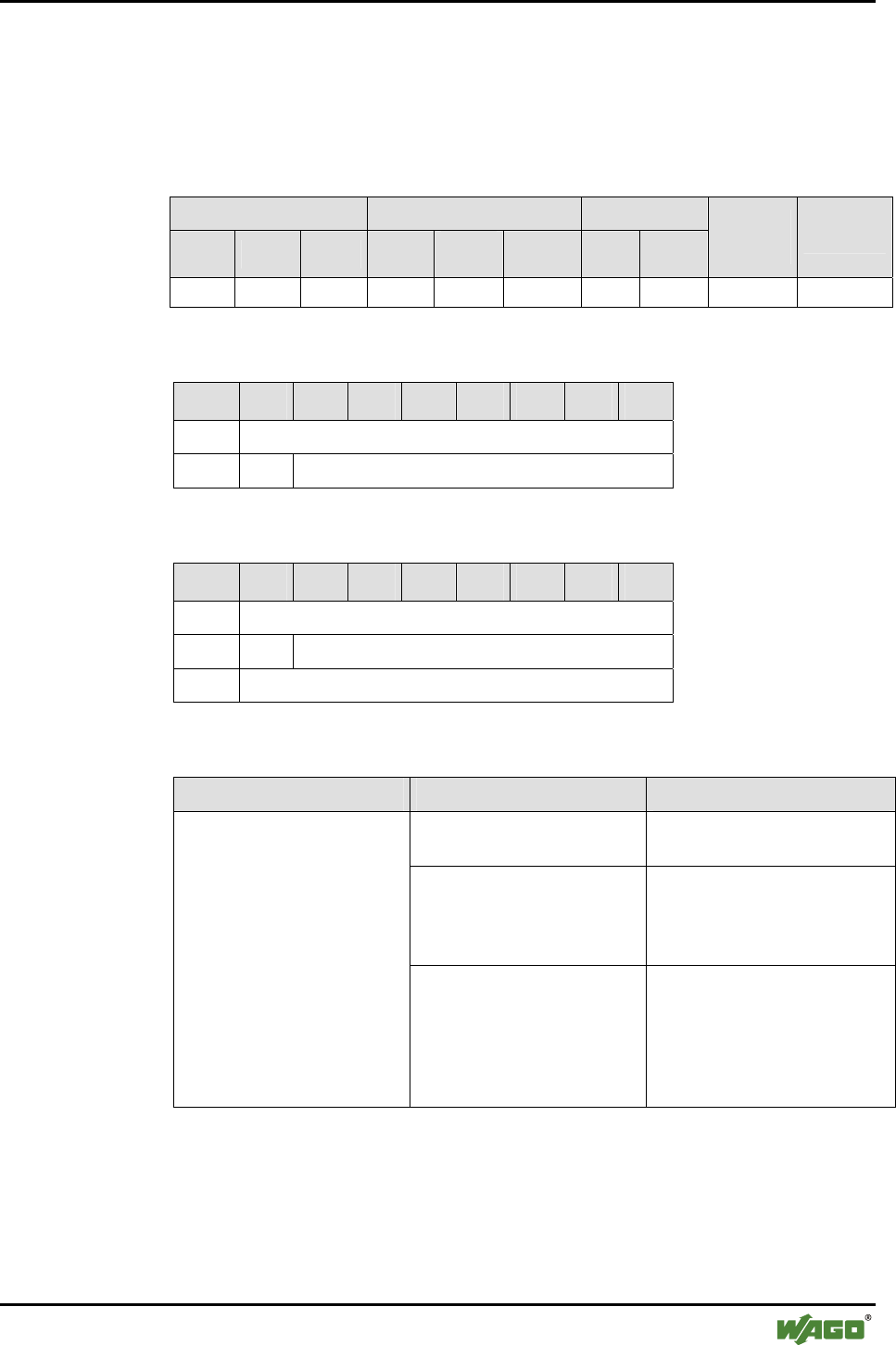
Appendix • 135
Mailbox Command References
WAGO-I/O-SYSTEM 750
I/O Modules
6.3.5.14 Read Local Authentication Mode (GetLocalAuthenticationMode, 0x4F)
With call up, the locally set authentication mode of the Bluetooth® subsystem
is read.
Conditions
Mailbox size Operating mode/profile Device role
6 12 18 Config. Real-
time Ad hoc Master Slave
Save
config. Restart
● ● ● ● - - ● ● - -
Request
Byte 27 26 25 24 23 22 21 20
0 MBX_GETAUTHENTICATIONMODE
1 T -
Response
Byte 27 26 25 24 23 22 21 20
0 MBX_GETAUTHENTICATIONMODE
1 T MBX_RESULT
2 MBX_AUTHENTICATION_MODE
Return values
Parameter Value Description
MBX_AUTHENTICATION
_NONE (0x01)
No authorization necessary
MBX_AUTHENTICATION
_PIN (0x02)
Authentication is conducted
with a PIN created from the
password at each establishment
of a connection.
MBX_AUTHENTICATION
_MODE
MBX_AUTHENTICAT ON
_LINKKEY (0x03)
Authorization through "Link
Key" (The PIN is not requested
with each new establishment of
a connection, but the "Link
Key" saved in the flash is
used).

136 • Appendix
Mailbox Command References
WAGO-I/O-SYSTEM 750
I/O Modules
6.3.5.15 Set Local Authentication Mode (SetLocalAuthenticationMode, 0x50)
With the call up "SetLocalAuthenticationMode", the local authentication
mode of the Bluetooth® subsystem is set. If the authentication is activated, the
modules authenticate each other at each connection establishment. This proc-
ess occurs, per Bluetooth® standard, under cryptographic safeguards.
If MBX_AUTHENTICATION_LINKKEY is set as the authentication mode,
an individual "Link Key" is calculated from the configured PIN during the
first connection (created from the password). If this key has been generated
once, the modules are considered to be "paired" (connected) and do not need
to repeat mutual authentication with a new connection. If the "Link Key" is
deleted, for example during a restart of the device or via "EraseLocalAuthen-
tication", then the password is requested again in order to calculate the "Link
Key". Accordingly, for external devices, a request to enter the password ap-
pears during the first or renewed authentication. In WAGO modules, the
password is archived in the Bluetooth® subsystem and does not have to be re-
entered once it has been correctly created.
In authentication mode MBX_AUTHENTICATION_PIN, an authentication is
performed with the PIN instead of using the "Link Key". Using WAGO mod-
ules, this is performed automatically via saved password; for external devices,
the password must generally be re-entered manually with each connection es-
tablishment.
Note
Authentication only ensures that communication partners detect each other's
identity. Protection from the tapping of data is not guaranteed by an authenti-
cation.
Authentication is the prerequisite for the encryption of data transmission.
Modules can only connect to each other if they have the same settings for
encryption, authentication and password.
Conditions
Mailbox size Operating mode/profile Device role
6 12 18 Config. Real-
time Ad hoc Master Slave
Save
config. Restart
● ● ● ● - - ● ● ● -
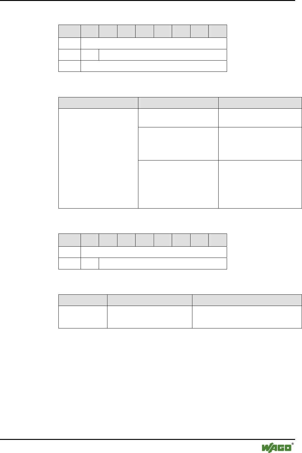
Appendix • 137
Mailbox Command References
WAGO-I/O-SYSTEM 750
I/O Modules
Request
Byte 27 26 25 24 23 22 21 20
0 MBX_SETAUTHENTICATIONMODE
1 T -
MBX_AUTHENTICATION_MODE
Arguments
Parameter Value Description
MBX_AUTHENTICATION
_NONE (0x01)
No authorization necessary
MBX_AUTHENTICATION
_PIN (0x02)
Authentication is conducted
with a PIN created from the
password at each establishment
of a connection.
MBX_AUTHENTICATION
_MODE
MBX_AUTHENTICATION
_LINKKEY (0x03)
Authorization through "Link
Key" (The PIN is not requested
with each new establishment of
a connection, rather the "Link
Key" saved in the flash is
used).
Response
Byte 27 26 25 24 23 22 21 20
0 MBX_SETAUTHENTICATIONMODE
1 T MBX_RESULT
Return values
Parameter Value Description
MBX_RESULT MBX_CMD_INVALID_ARG
No valid value passed with MBX_
AUTHENTICATION_MODE
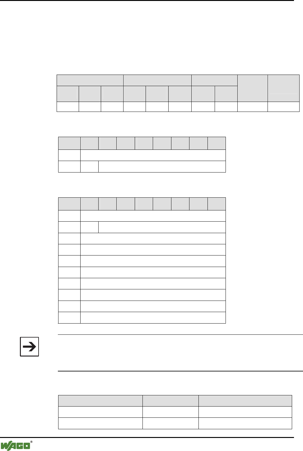
138 • Appendix
Mailbox Command References
WAGO-I/O-SYSTEM 750
I/O Modules
6.3.5.16 Read Local Bluetooth® Password (GetLocalPassphrase, 0x51)
With call up, the encryption mode for the wireless transmission is read out.
The password is transmitted as a byte value representation of ASCII charac-
ters and is at least 4 characters long.
Conditions
Mailbox size Operating mode/profile Device role
6 12 18 Config. Real-
time Ad hoc Master Slave
Save
config. Restart
- (●) (●) ● - - ● ● - -
Request
Byte 27 26 25 24 23 22 21 20
0 MBX_GETLOCALPASSPHRASE
1 T -
Response
Byte 27 26 25 24 23 22 21 20
0 MBX_GETLOCALPASSPHRASE
1 T MBX_RESULT
2 MBX_PASSPHRASE_Length
3 MBX_PASSPHRASE_Byte 1
4 MBX_PASSPHRASE_Byte 2
5 MBX_PASSPHRASE_Byte 3
6 MBX_PASSPHRASE_Byte 4
7 OPTIONAL PASSPHRASE_Byte 5
... …
17 OPTIONAL PASSPHRASE_Byte 15
Note
If the password is longer than the available mailbox, the excess bytes are cut off.
MBX_ PASSPHRASE _Length reproduces the actual password length.
Therefore, the real password may therefore deviate from the indicated length.
Return values
Parameter Value Description
MBX_PASSPHRASE_Length [4…15] Complete length of the password
MBX_ PASSPHRASE_Byte n Characters (ASCII) Password as ASCII representation
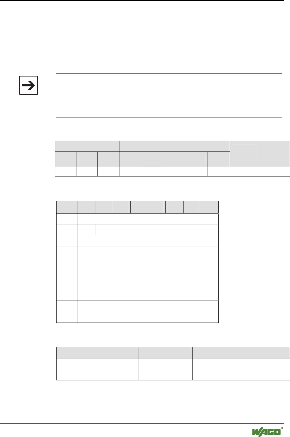
Appendix • 139
Mailbox Command References
WAGO-I/O-SYSTEM 750
I/O Modules
6.3.5.17 Write Local Bluetooth® Password (SetLocalPassphrase, 0x52)
With this command, the local password can be configured. The module calcu-
lates the "Link Key" from the locally saved password. This is necessary during
active authentication for the establishment and data encryption. The Blue-
tooth® password must therefore be identical for all devices intended to com-
municate with each other.
Note
Security quality depends on the selected password. The password should be
as long as possible and selected randomly.
Modules can only connect to each other if they have the same settings for
encryption, authentication and password.
Conditions
Mailbox size Operating mode/profile Device role
6 12 18 Config. Real-
time Ad hoc Master Slave
Save
config. Restart
- (●) (●) ● - - ● ● ● -
Request
Byte 27 26 25 24 23 22 21 20
0 MBX_SETLOCALPASSPHRASE
1 T -
2 MBX_PSW_Length
3 MBX_PSW_Byte 1
4 MBX_PSW_Byte 2
5 MBX_PSW_Byte 3
6 MBX_PSW_Byte 4
7 OPTIONAL MBX_PASSPHRASE_Byte 5
... …
17 OPTIONAL MBX_PASSPHRASE_Byte 15
Arguments
Parameter Value Description
MBX_PASSPHRASE_Length [4...15] Password length
MBX_ PASSPHRASE_Byte n Characters (ASCII) Password as ASCII representation

140 • Appendix
Mailbox Command References
WAGO-I/O-SYSTEM 750
I/O Modules
Response
Byte 27 26 25 24 23 22 21 20
0 MBX_SETLOCALPASSPHRASE
1 T MBX_RESULT
Return values
Parameter Value Description
MBX_RESULT MBX_CMD_INVALID_ARG The password length is shorter than 4 char-
acters and is not long enough or
MBX_PASSPHRASE_Length indicates a
value that is larger than the payload of the
mailbox.

Appendix • 141
Mailbox Command References
WAGO-I/O-SYSTEM 750
I/O Modules
6.3.5.18 Delete Locally Saved Authorization (EraseLocalAuthentication, 0x53)
With call up, the locally saved information for authorization is deleted. Then a
warm start is carried out.
Conditions
Mailbox size Operating mode/profile Device role
6 12 18 Config. Real-
time Ad hoc Master Slave
Save
config. Restart
● ● ● ● - - ● ● - -
Request
Byte 27 26 25 24 23 22 21 20
0 MBX_ERASELOCALAUTHENTICATION
1 T -
Response
Byte 27 26 25 24 23 22 21 20
0 MBX_ERASELOCALAUTHENTICATION
1 T MBX_RESULT
Return values
Parameter Value Description
- - -
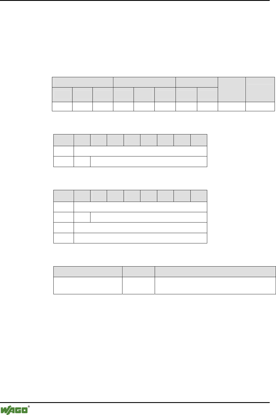
142 • Appendix
Mailbox Command References
WAGO-I/O-SYSTEM 750
I/O Modules
6.3.5.19 Read Length of the Flash Configuration (GetLocalDeviceConfigLen,
0x54)
With call up, the length (in bytes) of the locally saved configuration in the
flash of the Bluetooth® subsystem is passed back. This information is used by
the PLC for interpretation of data from the block commands.
Conditions
Mailbox size Operating mode/profile Device role
6 12 18 Config. Real-
time Ad hoc Master Slave
Save
config. Restart
● ● ● ● - - ● ● - -
Request
Byte 27 26 25 24 23 22 21 20
0 MBX_GETLOCALDEVICECONFIGLEN
1 T -
Response
Byte 27 26 25 24 23 22 21 20
0 MBX_GETLOCALDEVICECONFIGLEN
1 T MBX_RESULT
2 MBX_CONFIG_LENGTH (LSB)
3 MBX_CONFIG_LENGTH (MSB)
Return values
Parameter Value Description
MBX_CONFIG_LENGTH [0…65535] Length of the configuration (number of bytes)
saved in the flash.
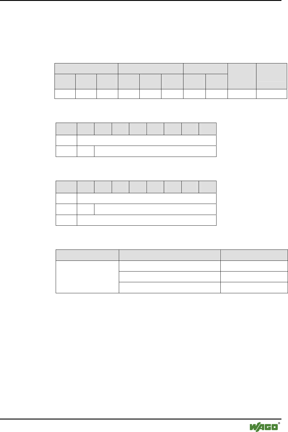
Appendix • 143
Mailbox Command References
WAGO-I/O-SYSTEM 750
I/O Modules
6.3.5.20 Read Role of the Local Device (GetLocalDeviceRole, 0x55)
This command queries the role of the local Bluetooth® module in the piconet
(master or slave).
Conditions
Mailbox size Operating mode/profile Device role
6 12 18 Config. Real-
time Ad hoc Master Slave
Save
config. Restart
● ● ● ● ● ● ● ● - -
Request
Byte 27 26 25 24 23 22 21 20
0 MBX_GETLOCALDEVICEROLE
1 T -
Response
Byte 27 26 25 24 23 22 21 20
0 MBX_GETLOCALDEVICEROLE
1 T MBX_CMD_RESULT
2 MBX_DEVICE_ROLE
Return values
Parameter Value Description
MBX_ROLE_COORDINATOR(0x01) Device role of master
reserved (0x02) Reserved
MBX_DEVICE_ROLE
MBX_ROLE_ENDDEVICE (0x03) Device role of slave
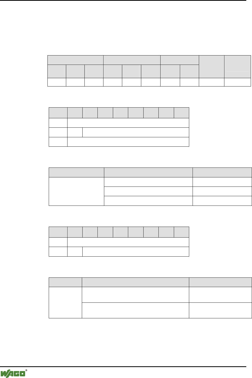
144 • Appendix
Mailbox Command References
WAGO-I/O-SYSTEM 750
I/O Modules
6.3.5.21 Set Role of the Local Device (SetLocalDeviceRole, 0x56)
This command establishes the role of the local Bluetooth® module in the pi-
conet (master or slave).
Conditions
Mailbox size Operating mode/profile Device role
6 12 18 Config. Real-
time Ad hoc Master Slave
Save
config. Restart
● ● ● ● - - ● ● - -
Request
Byte 27 26 25 24 23 22 21 20
0 MBX_SETLOCALDEVICEROLE
1 T -
2 MBX_DEVICE_ROLE
Arguments
Parameter Value Description
MBX_ROLE_COORDINATOR (0x01) Master
MBX_ROLE_ROUTER (0x02) Router
MBX_DEVICE_ROLE
MBX_ROLE_ENDDEVICE (0x03) Slave
Response
Byte 27 26 25 24 23 22 21 20
0 MBX_SETLOCALDEVICEROLE
1 T MBX_CMD_RESULT
Return values
Parameter Value Description
MBX_CMD_DENIED_NOT_IMPLEMENTED The parameter is not im-
plemented (router)
MBX_CMD_
RESULT
MBX_CMD_INVALID_ARG Invalid value for
MBX_DEVICE_ROLE

Appendix • 145
Mailbox Command References
WAGO-I/O-SYSTEM 750
I/O Modules
6.3.5.22 Restore Factory Settings (SetFactorySettings, 0x57)
With call up, the locally saved configuration in the flash is overwritten by the
factory settings. The Bluetooth® subsystem is then restarted.
Conditions
Mailbox size Operating mode/profile Device role
6 12 18 Config. Real-
time Ad hoc Master Slave
Save
config. Restart
● ● ● ● ● ● ● ● ● ●
Request
Byte 27 26 25 24 23 22 21 20
0 MBX_SETFACTORYSETTINGS
1 T -
Response
Byte 27 26 25 24 23 22 21 20
0 MBX_SETFACTORYSETTINGS
1 T MBX_RESULT
Return values
Parameter Value Description
- - -
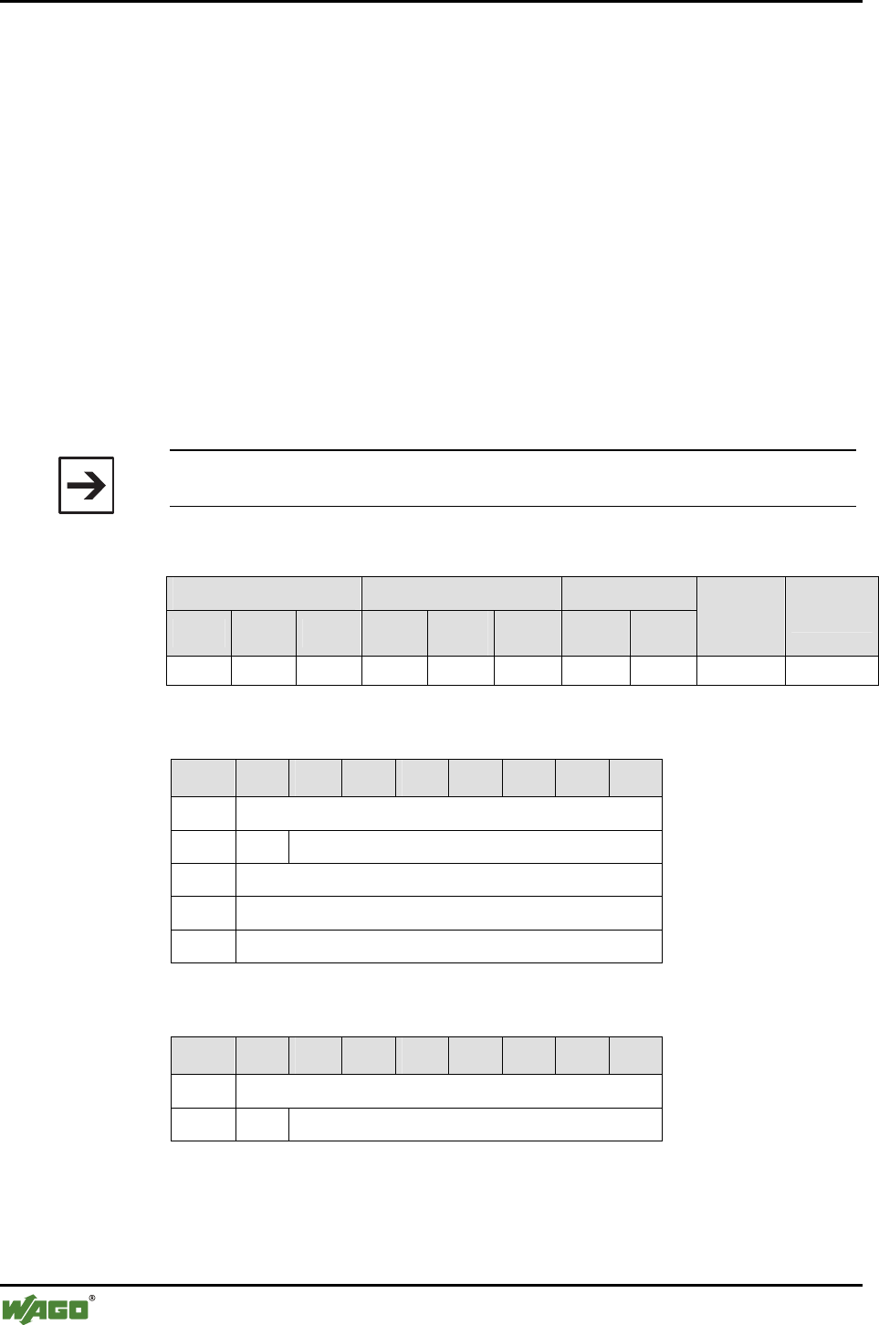
146 • Appendix
Mailbox Command References
WAGO-I/O-SYSTEM 750
I/O Modules
6.3.5.23 Search for Remote Bluetooth® Device in the Wireless Network (Scan-
RemoteDevices, 0x80)
With call up, the search for remote bus modules in the wireless network is
triggered. The search process is asynchronous; i.e., the result is not immedi-
ately available. As long as the search runs, the wireless module is not avail-
able for any other function. Functions that do not use the wireless module are
carried out normally. If the search concludes, found devices are entered in a
list from which they can be individually queried with the command "GetRe-
moteDeviceMacID". The complete CoD for the WAGO Bluetooth® RF Trans-
ceiver 750-644 is: 0x0020F8 (hexadecimal).
To limit the search to certain devices, a Class-of-Device (CoD) can be indi-
cated. If a CoD not equal to 0 is used, only those devices are found that have
this exact CoD. If CoD = 0 is used, all devices in the environment are sought
out.
Note
The complete result of the inquiry can be read with the DLD commands.
Conditions
Mailbox size Operating mode/profile Device role
6 12 18 Config. Real-
time Ad hoc Master Slave
Save
config. Restart
● ● ● ● - - ● ● - -
Request
Byte 27 26 25 24 23 22 21 20
0 MBX_SCANREMOTEDEVICES
1 T -
2 MBX_COD (LSB)
3 MBX_COD
4 MBX_COD (MSB)
Response
Byte 27 26 25 24 23 22 21 20
0 MBX_SCANREMOTEDEVICES
1 T MBX_RESULT

Appendix • 147
Mailbox Command References
WAGO-I/O-SYSTEM 750
I/O Modules
Return values
Parameter Value Description
MBX_RESULT MBX_CMD_DENIED_BUSY A running search process or another func-
tion is blocking the wireless module.
MBX_COD 24 bits Class-of-Device for those devices that are
to be sought. With MBX_COD = 0x0, the
CoD is ignored.

148 • Appendix
Mailbox Command References
WAGO-I/O-SYSTEM 750
I/O Modules
6.3.5.24 Read MAC-ID of a Remote Bluetooth® Device (GetRemoteDeviceMacID,
0x81)
This command accesses a list of visible Bluetooth® devices in the environment
and queries the Bluetooth® MAC-ID of a remote device. The prerequisite for
this command is the prior execution of a search process with the command
"ScanRemoteDevices", which initiates the creation of this list. If an attempt is
made to access the list before the search process is complete, the command
answers with MBX_CMD_DENIED_BUSY. In this case, the query should be
repeated after a certain waiting period.
Conditions
Mailbox size Operating mode/profile Device role
6 12 18 Config. Real-
time Ad hoc Master Slave
Save
config. Restart
- ● ● ● - - ● ● - -
Request
Byte 27 26 25 24 23 22 21 20
0 MBX_GETREMOTEDEVICEMACID
1 T -
2 MBX_DEVICE_INDEX
Arguments
Parameter Value Description
MBX_DEVICE_INDEX [0 ...15]
Index of the device whose MAC-ID is to be read. A
maximum of 16 found devices are administered.
Response
Byte 27 26 25 24 23 22 21 20
0 MBX_GETREMOTEDEVICEMACID
1 T MBX_RESULT
MBX_NR_FOUND_DEVICES
2 MBX_MACID_BYTE (LSB)
3 MBX_MACID_BYTE
4 MBX_MACID_BYTE
5 MBX_MACID_BYTE
6 MBX_MACID_BYTE
7 MBX_MACID_BYTE (MSB)

Appendix • 149
Mailbox Command References
WAGO-I/O-SYSTEM 750
I/O Modules
Return values
Parameter Value Description
MBX_CMD_DENIED_
BUSY
The search process has not yet been
stated or concluded.
MBX_RESULT
MBX_CMD_OUT_OF_
RANGE
The indicated index is greater than or
equal to the number of the devices
found. Or, no Bluetooth® device with
the indicated Class-of-Device was
found.
MBX_MACID_BYTE Bytes of the MAC-ID Valid if MBX_RESULT =
MBX_CMD_OK
MBX_NR_FOUND_
DEVICES
[0...15] Number of devices found; if no devices
were found, this parameter has the
value 0 and MBX_RESULT has the
value MBX_CMD_OUT_OF_RANGE
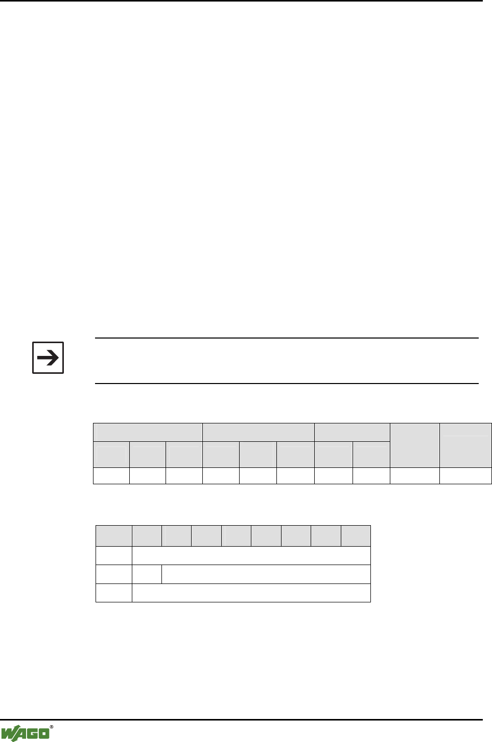
150 • Appendix
Mailbox Command References
WAGO-I/O-SYSTEM 750
I/O Modules
6.3.5.25 Read Device Name of a Remote Bluetooth® Device
(GetRemoteDeviceName, 0x82)
With call up, the name of a disconnected I/O module in the wireless network
is queried (compare Appendix 6.3.5.24, GetRemoteDeviceMacID). Since this
information must be requested via remote device and no quick response can be
guaranteed, the first request starts with the name resolution. However, it re-
sponds with MBX_CMD_DENIED_BUSY without returning the name. Re-
peating the request delivers both MBX_CMD_OK and the character string of
the requested device name as soon as the name has been determined. The call
up returns an error if "ScanRemoteDevices" has not been called previously
and the search (first call up) has not been completed successfully. As long as
the name call up runs, the wireless module is not available for any other func-
tions. Functions that do not use the wireless module are performed normally.
If the name query has been completed, a new call up from "GetRemoteDe-
viceName" delivers the Bluetooth® name of the remote device (compare Ap-
pendix 6.3.5.1, "GetLocalDeviceName"). A maximum of (mailbox size - 3)
characters are displayed.
The Bluetooth® name of remote devices may also exceed the length (15 char-
acters) that can be displayed in the largest mailbox setting (18 bytes). In this
case, the complete name can be read by block transfer, however.
Note
Before calling up "GetRemoteDeviceName", the command "ScanRemoteDe-
vices" (see Appendix 6.3.5.23) must be executed.
Conditions
Mailbox size Operating mode/profile Device role
6 12 18 Config. Real-
time Ad hoc Master Slave
Save
config. Restart
(●) (●) (●) ● - - ● ● - -
Request
Byte 27 26 25 24 23 22 21 20
0 MBX_GETREMOTEDEVICENAME
1 T -
2 MBX_DEVICE_INDEX
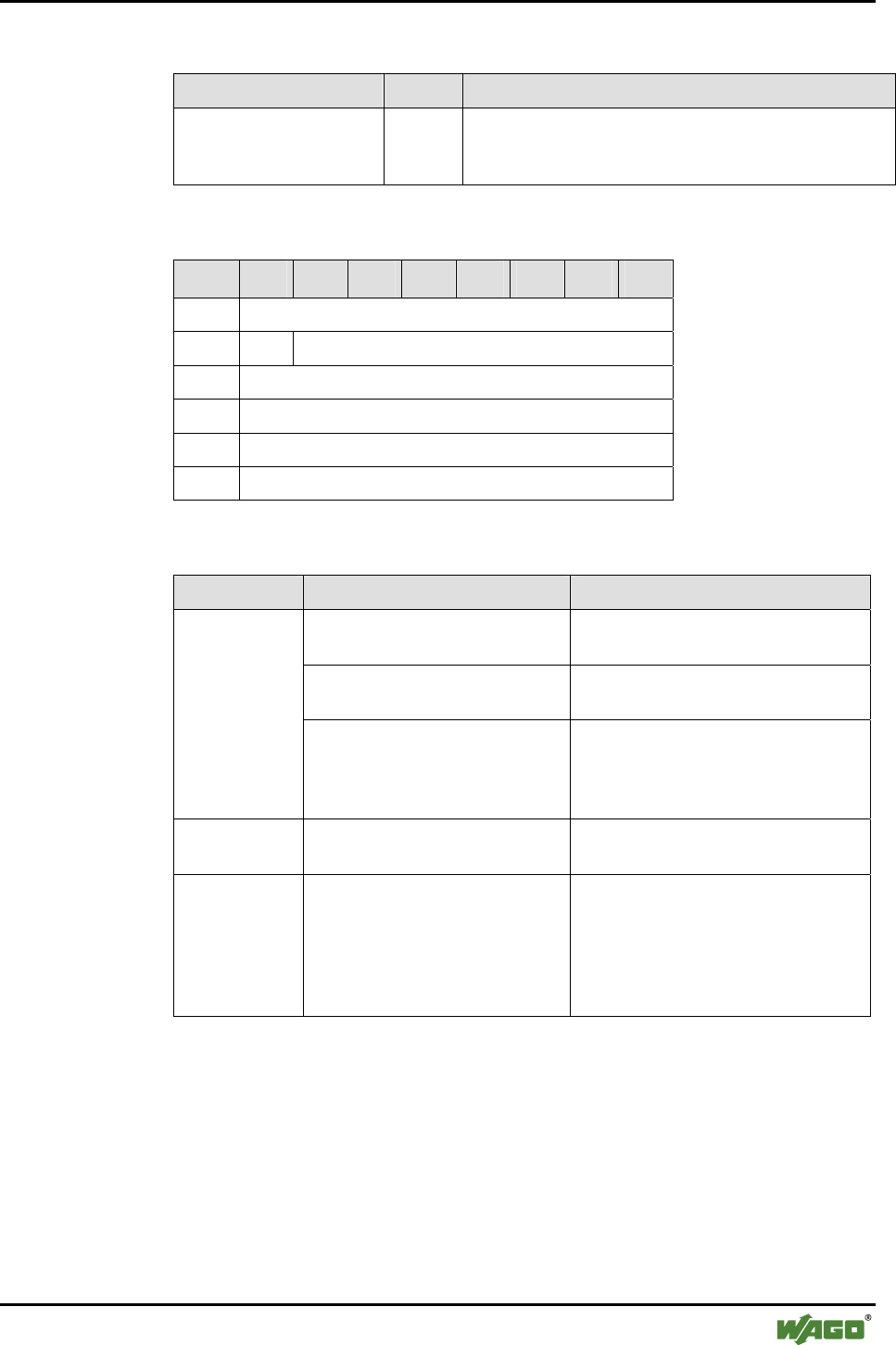
Appendix • 151
Mailbox Command References
WAGO-I/O-SYSTEM 750
I/O Modules
Arguments
Parameter Value Description
MBX_DEVICE_INDEX [0 ...15] List index for the return of the device name. The index
must be smaller than the number of devices found in the
search process.
Response
Byte 27 26 25 24 23 22 21 20
0 MBX_GETREMOTEDEVICENAME
1 T MBX_RESULT
2 MBX_NAME_LENGTH
3 CHAR1
... ...
17 CHAR15
Return values
Parameter Value Description
MBX_CMD_OUT_OF_RANGE No valid device was found in the scan
list for the delivered index.
MBX_CMD_DENIED_BUSY The search process has not yet been
stated or not yet concluded.
MBX_
RESULT
MBX_CMD_TIMEOUT The remote device has rejected the
name query or has not responded
within the time prescribed by the
Bluetooth® standard.
MBX_NAME
_LENGTH
[0...255] Number of characters in the complete
name.
CHARn ASCII characters Characters of the device name in
ASCII code
Example: ABC
A = CHAR1 = 0x41
B = CHAR2 = 0x42
C = CHAR3 = 0x43

152 • Appendix
Mailbox Command References
WAGO-I/O-SYSTEM 750
I/O Modules
6.3.5.26 Enter External Device in the Table of Authorized Devices
(AllowRemoteDevice, 0x83)
This command allows a remote device to access the local device. The MAC-
ID of the remote device is also entered in a table of the Bluetooth® subsystem.
Two device types are differentiated. Both types are entered in different tables:
WAGO devices for real-time communication:
WAGO_DEVICE (0x20...0x26)
External devices for communication over SPP[1] or PAN[2]:
EXTERNAL_DEVICE (0x10...0x15)
[1] Bluetooth® Specification: device supports the Serial Port Profile (SPP)
[2] Bluetooth® Specification: device supports the Personal Area Network (PAN) Profile
Note
Before an entered WAGO device is actually authorized for access, it must be
activated using command "BindRemoteDevice".
The access authorization can be withdrawn again via command "UnbindRe-
moteDevice" without requiring deletion of the device from the table.
Entries can be deleted from the table by overwriting with the MAC-ID
00:00:00:00:00:00. The affected slot is filled with zeros and no data is trans-
mitted to it. Changes to the device blocks do not change anything in the proc-
ess image mapping.
A MAC-ID (except for 00:00:00:00:00:00) may never occur more than once
in the table.
Conditions
Mailbox size Operating mode/profile Device role
6 12 18 Config. Real-
time Ad hoc Master Slave
Save
config. Restart
- ● ● ● - - ● ● ● -
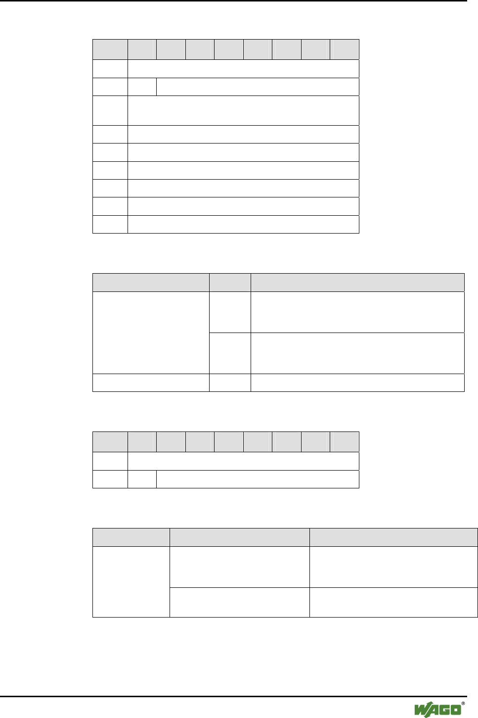
Appendix • 153
Mailbox Command References
WAGO-I/O-SYSTEM 750
I/O Modules
Request
Byte 27 26 25 24 23 22 21 20
0 MBX_ALLOWREMOTEDEVICE
1 T -
2 MBX_TARGET_TABLE_AND_
INDEX
3 MAC_ID_Byte 0 (LSB)
4 MAC_ID_Byte 1
5 MAC_ID_Byte 2
6 MAC_ID_Byte 3
7 MAC_ID_Byte 4
8 MAC_ID_Byte 5 (MSB)
Arguments
Parameter Value Description
Bit 0…3 Table Index
Index 0...6 for WAGO devices of slots 1...7
Index 0…5 for external devices of slots 8...12
MBX_TARGET_TABLE_
AND_INDEX
Bit 4…7 Target table
"2" for WAGO_DEVICE (slots 1...7)
"1" for EXTERNAL_DEVICE (slots 8…12)
MAC ID Byte n [0...255] The bytes of the MAC-ID to be entered
Response
Byte 27 26 25 24 23 22 21 20
0 MBX_ALLOWREMOTEDEVICE
1 T MBX_RESULT
Return values
Parameter Value Description
MBX_CMD_OUT_OF_RANGE A maximum of seven WAGO devices
or six external devices can be config-
ured. This number has been exceeded.
MBX_RESULT
MBX_CMD_INVALID_ARG The indicated MAC-ID is already in the
table or a false table ID has been given.
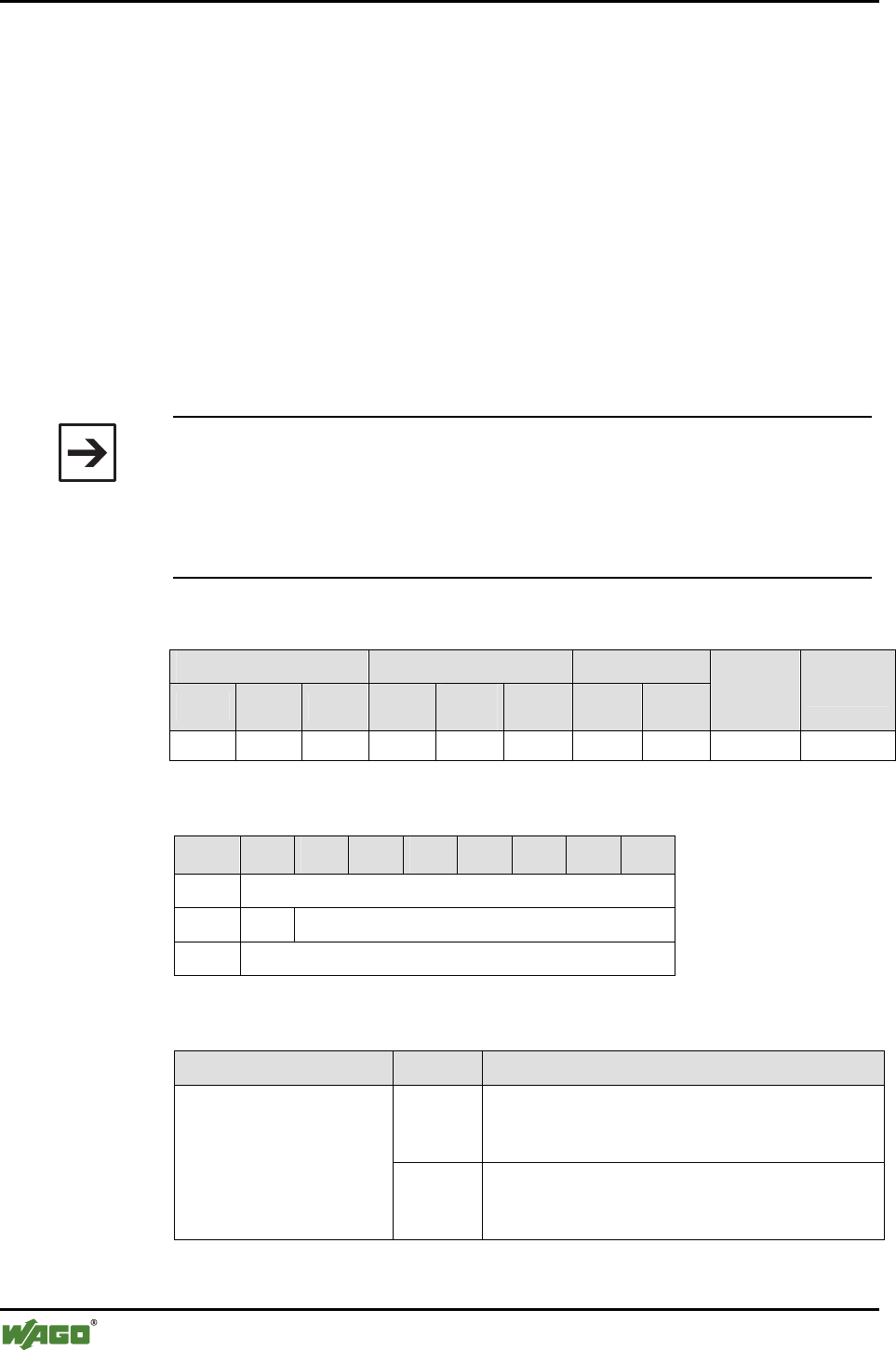
154 • Appendix
Mailbox Command References
WAGO-I/O-SYSTEM 750
I/O Modules
6.3.5.27 Read Back External Device from the Table of Authorized Devices
(GetAllowedRemoteDevices, 0x84)
This command reads out and returns the MAC-ID of a remote device from the
table of authorized devices of the Bluetooth® subsystem. There are two types
of external devices entered in different tables:
WAGO devices for real-time communication:
WAGO_DEVICE (0x20...0x26)
External devices for communication over SPP[1] or PAN[2]:
EXTERNAL_DEVICE (0x10…0x15)
[1] Bluetooth® Specification: device supports the Serial Port Profile (SPP)
[2] Bluetooth® Specification: device supports the Personal Area Network (PAN) Profile
Note
Before an entered WAGO device is actually authorized for access, it must be
activated using the command "BindRemoteDevice".
The access authorization can be withdrawn again using the command "Un-
bindRemoteDevice" without making it necessary to delete the device from
the table.
Conditions
Mailbox size Operating mode/profile Device role
6 12 18 Config. Real-
time Ad hoc Master Slave
Save
config. Restart
- ● ● ● - - ● ● - -
Request
Byte 27 26 25 24 23 22 21 20
0 MBX_GETALLOWEDREMOTEDEVICE
1 T -
2 MBX_TARGET_TABLE_AND_INDEX
Arguments
Parameter Value Description
Bit 0…3 Table Index
Index 0...6 for WAGO devices of slots 1...7
Index 0...5 for external devices of slots 8...12
MBX_TARGET_TABLE_
AND_INDEX
Bit 4…7 Target table
"2" for WAGO_DEVICE (slots 1...7)
"1" for EXTERNAL_DEVICE (slots 8...12)
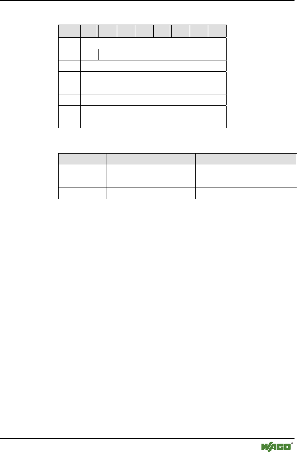
Appendix • 155
Mailbox Command References
WAGO-I/O-SYSTEM 750
I/O Modules
Response
Byte 27 26 25 24 23 22 21 20
0 MBX_GETALLOWEDREMOTEDEVICE
1 T MBX_RESULT
2 MAC_ID_Byte 0 (LSB)
3 MAC_ID_Byte 1
4 MAC_ID_Byte 2
5 MAC_ID_Byte 3
6 MAC_ID_Byte 4
7 MAC_ID_Byte 5 (MSB)
Return values
Parameter Value Description
MBX_CMD_OUT_OF_RANGE An index greater than 6 was used. MBX_RESULT
MBX_CMD_INVALID_ARG No valid target table chosen.
MAC ID Byte n [0...255] The bytes of the MAC-ID read back.
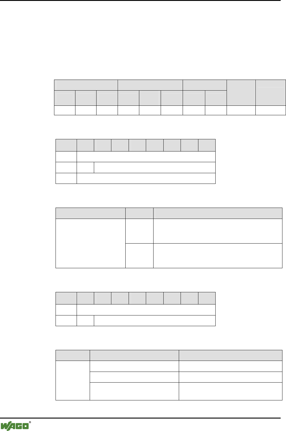
156 • Appendix
Mailbox Command References
WAGO-I/O-SYSTEM 750
I/O Modules
6.3.5.28 Grant Access Authorization for a Device (BindRemoteDevice, 0x85)
A remote device from the table of authorized devices in the Bluetooth® sub-
system is activated for connection establishment. The MAC-ID of the remote
device must have been entered in the table of authorized devices beforehand
(see Appendix 6.3.5.26).
Conditions
Mailbox size Operating mode/profile Device role
6 12 18 Config. Real-
time Ad hoc Master Slave
Save
config. Restart
● ● ● ● - - ● ● - -
Request
Byte 27 26 25 24 23 22 21 20
0 MBX_BINDREMOTEDEVICE
1 T -
2 MBX_TARGET_TABLE_AND_INDEX
Arguments
Parameter Value Description
Bit 0…3 Table Index
Index 0...6 for WAGO devices of slots 1...7
Index 0…5 for external devices of slots 8...12
MBX_TARGET_TABLE_
AND_INDEX
Bit 4…7 Target table
"2" for WAGO_DEVICE (slots 1...7)
"1" for EXTERNAL_DEVICE (slots 8...12)
Response
Byte 27 26 25 24 23 22 21 20
0 MBX_BINDREMOTEDEVICE
1 T MBX_RESULT
Return values
Parameter Value Description
MBX_CMD_OUT_OF_RANGE An index greater than 6 was used.
MBX_CMD_INVALID_ARG No valid target table chosen.
MBX_
RESULT
MBX_CMD_GENERAL_ERROR Chosen entry does not contain a valid
MAC address.

Appendix • 157
Mailbox Command References
WAGO-I/O-SYSTEM 750
I/O Modules
6.3.5.29 Delete Access Authorization for a Device (UnbindRemoteDevice, 0x86)
Access authorization of a remote device is deactivated. When this occurs, the
MAC-ID entered in the table space and associated data, such as the "User-
FriendlyName" are retained. However no connection to the device is estab-
lished and any pre-existing connection is interrupted. If the command is exe-
cuted in communication mode, this setting is temporary - at the next restart,
the connection is re-established. This offers the possibility of temporarily ex-
cluding defective remote devices from the network without changing the con-
figuration. If no attempt is made to connect the device after restart, the com-
mand must be called up in the configuration mode.
Conditions
Mailbox size Operating mode/profile Device role
6 12 18 Config. Real-
time Ad hoc Master Slave
Save
config. Restart
● ● ● ● ● ● ● ● - * -
* Setting is temporary in communication mode. In configuration mode,
the setting is saved, comparable to other settings, during a warm start.
Request
Byte 27 26 25 24 23 22 21 20
0 MBX_UNBINDREMOTEDEVICE
1 T -
2 MBX_TABLE_TABLE_AND_INDEX
Arguments
Parameter Value Description
Bit 0…3 Table Index
Index 0...6 for WAGO devices of slots 1...7
Index 0...5 for external devices of slots 8...12
MBX_TARGET_TABLE_
AND_INDEX
Bit 4…7 Target table
"2" for WAGO_DEVICE (slots 1...7)
"1" for EXTERNAL_DEVICE (slots 8...12)
Response
Byte 27 26 25 24 23 22 21 20
0 MBX_UNBINDREMOTEDEVICE
1 T MBX_RESULT

158 • Appendix
Mailbox Command References
WAGO-I/O-SYSTEM 750
I/O Modules
Return values
Parameter Value Description
MBX_CMD_OUT_OF_RANGE An index greater than 6 was used. MBX_RESULT
MBX_CMD_INVALID_ARG No valid target table chosen.

Appendix • 159
Mailbox Command References
WAGO-I/O-SYSTEM 750
I/O Modules
6.3.5.30 Read Access Authorization for Remote Devices (GetBoundRemoteDe-
vices, 0x87)
This command reads back which of the remote devices entered in the table
have an activated access authorization.
The authorization can be activated using the command "BindRemoteDevice"
and deactivated using "UnbindRemoteDevice".
Conditions
Mailbox size Operating mode/profile Device role
6 12 18 Config. Real-
time Ad hoc Master Slave
Save
config. Restart
● ● ● ● ● ● ● ● - -
Request
Byte 27 26 25 24 23 22 21 20
0 MBX_GETBOUNDREMOTEDEVICES
1 T -
Response
Byte 27 26 25 24 23 22 21 20
0 MBX_GETBOUNDREMOTEDEVICES
1 T MBX_RESULT
2 MBX_BOUND_DEVICES_WAGO
3 MBX_BOUND_DEVICES_EXTERN
Return values
Parameter Value Description
MBX_BOUND_
DEVICES_WAGO
0x00 (no WAGO device linked)
0x7F (all WAGO devices linked)
Bit 7 is always equal to 0
Bit assignment according to
the device index in the table of
WAGO devices for real-time
communication.
MBX_BOUND_
DEVICES_EXTERN
0x00 (no external device linked)
0x3F (all external devices linked)
Bit 6 and 7 are always equal to 0
Bit assignment according to
the device index in the table of
external devices for communi-
cation over SPP or PAN.
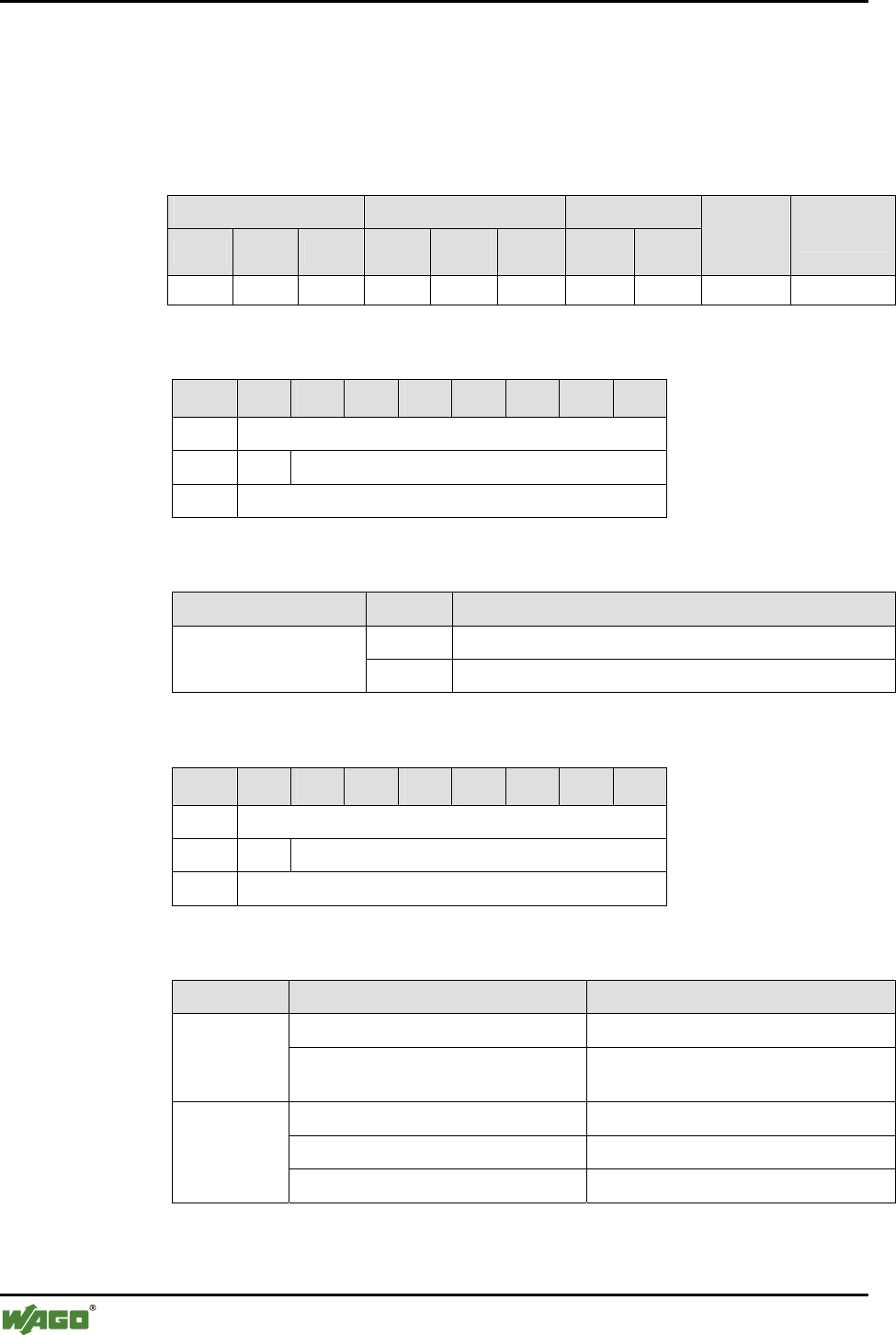
160 • Appendix
Mailbox Command References
WAGO-I/O-SYSTEM 750
I/O Modules
6.3.5.31 Read Back the QoS Settings (GetConnectionQoS, 0x88)
This command reads back the settings of the Quality-of-Service (QoS) of a
connection.
Conditions
Mailbox size Operating mode/profile Device role
6 12 18 Config. Real-
time Ad hoc Master Slave
Save
config. Restart
● ● ● ● - - ● ● - -
Request
Byte 27 26 25 24 23 22 21 20
0 MBX_GETCONNECTIONQOS
1 T -
2 MBX_TARGET_TABLE_AND_INDEX
Arguments
Parameter Value Description
Bit 0…3 Table index: Index 0…6 for WAGO devices of slots 1...7 MBX_TARGET_
TABLE_AND_INDEX Bit 4…7 Target table, "2" for WAGO_DEVICE (slots 1...7)
Response
Byte 27 26 25 24 23 22 21 20
0 MBX_GETCONNECTIONQOS
1 T MBX_RESULT
2 MBX_QOS_SETTINGS
Return values
Parameter Value Description
MBX_CMD_OUT_OF_RANGE No error occurred MBX_
RESULT MBX_CMD_INVALID_ARG Index too large or WAGO table not
chosen
MBX_BQM_NONE (0x01) No QoS activated (standard)
MBX_BQM_BEST_EFFORT (0x02) QoS is active in the "Best Effort" mode
MBX_QOS
_SETTINGS
MBX_BQM_GUARANTEED (0x03) QoS is active in the "Guaranteed" mode
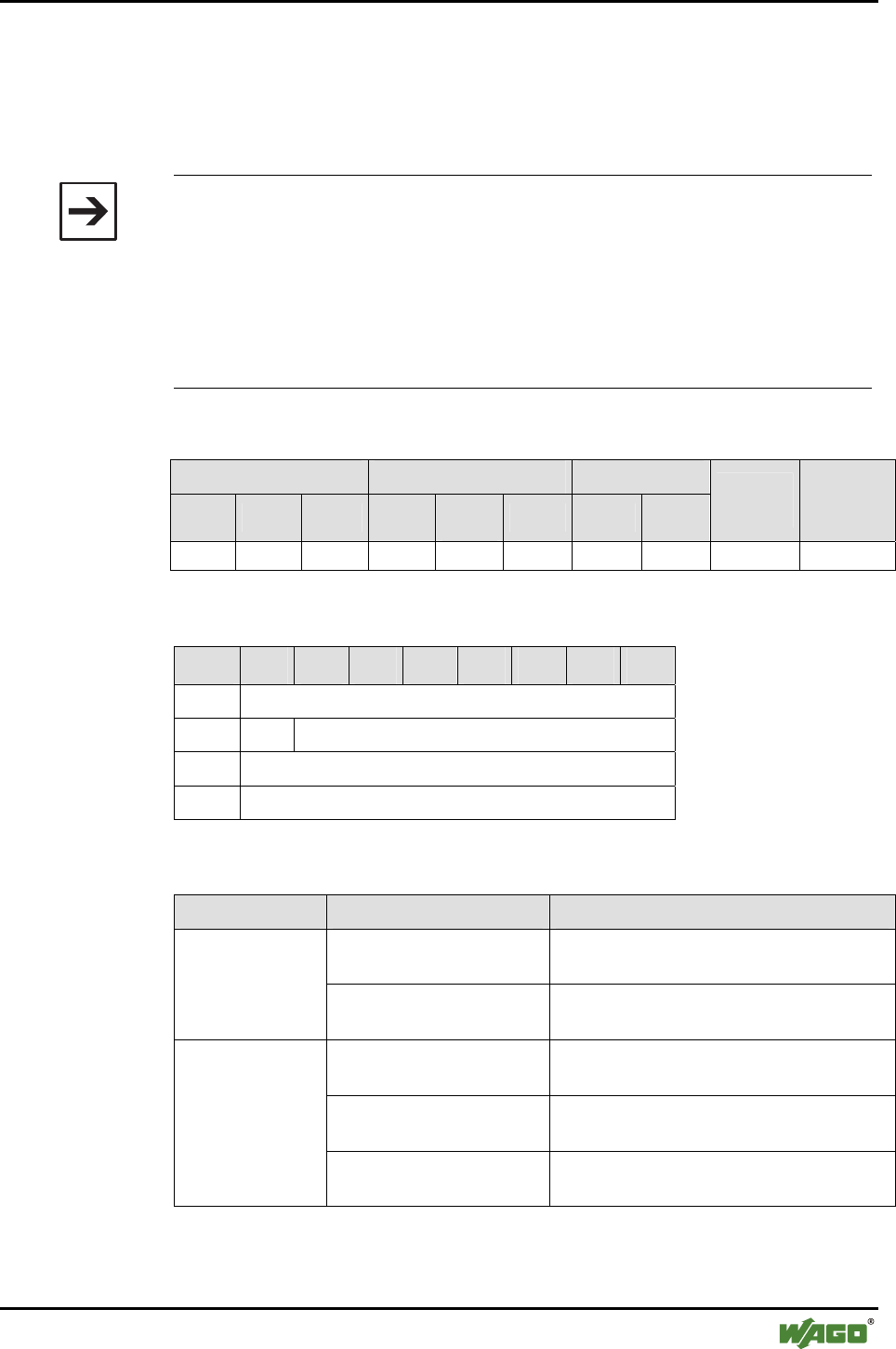
Appendix • 161
Mailbox Command References
WAGO-I/O-SYSTEM 750
I/O Modules
6.3.5.32 Set the QoS Settings (SetConnectionQoS, 0x89)
This command assigns the settings of the Quality-of-Service (QoS) for a con-
nection. The settings do not take effect until the module is switched over to
master mode.
Note
The master can connect to a maximum of 3 slaves with activated QoS. QoS
can only be set for WAGO devices. It improves latency by reducing devia-
tions (outliers).
Since the Bluetooth® subsystem of the Bluetooth® module has already been
optimized for maximum performance, the influence on time behavior in the
real-time profile is marginal. Therefore, it is recommended that you keep the
factory setting MBX_BQM_NONE.
Conditions
Mailbox size Operating mode/profile Device role
6 12 18 Config. Real-
time Ad hoc Master Slave
Save
config. Restart
● ● ● ● - - ● ● - -
Request
Byte 27 26 25 24 23 22 21 20
0 MBX_SETCONNECTIONQOS
1 T -
2 MBX_TARGET_TABLE_AND_INDEX
3 MBX_QOS_SETTINGS
Arguments
Parameter Value Description
Bit 0…3 Table index
Index 0...6 for WAGO devices of slots 1...7
MBX_TARGET_
TABLE_AND_
INDEX Bit 4…7 Target table
"2" for WAGO_DEVICE (slots 1...7)
MBX_BQM_NONE
(0x01)
No QoS activated (standard)
MBX_BQM_BEST_
EFFORT (0x02)
QoS is active in the "Best Effort" mode
MBX_QOS_
SETTINGS
MBX_BQM_
GUARANTEED (0x03)
QoS is active in the "Guaranteed" mode

162 • Appendix
Mailbox Command References
WAGO-I/O-SYSTEM 750
I/O Modules
Response
Byte 27 26 25 24 23 22 21 20
0 MBX_SETCONNECTIONQOS
1 T MBX_RESULT
Return values
Parameter Value Description
MBX_CMD_OUT_OF_RANGE An index greater than 6 was used. MBX_RESULT
MBX_CMD_INVALID_ARG No valid target table was used or an
invalid value for
MBX_QOS_SETTINGS was chosen.
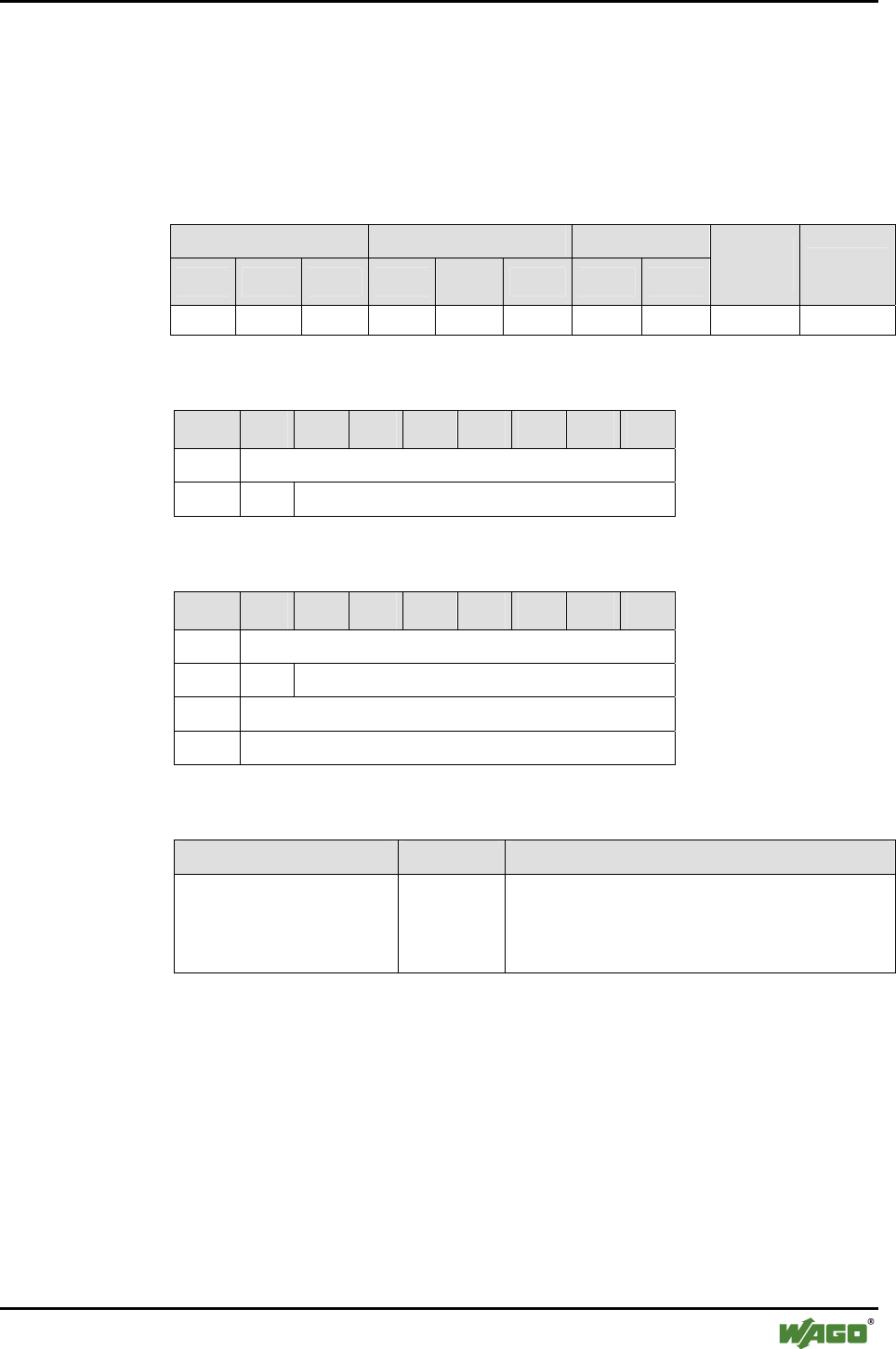
Appendix • 163
Mailbox Command References
WAGO-I/O-SYSTEM 750
I/O Modules
6.3.5.33 Read Back Time Settings - Between Two Attempts to Establish a Con-
nection (GetReconnectionTimePeriod, 0x8A)
This command reads back the waiting time between two attempts to re-
establish the connection to a bus module.
Conditions
Mailbox size Operating mode/profile Device role
6 12 18 Config. Real-
time Ad hoc Master Slave
Save
config. Restart
● ● ● ● - - ● ● - -
Request
Byte 27 26 25 24 23 22 21 20
0 MBX_GETRECONNECTIONTIMEPERIOD
1 T -
Response
Byte 27 26 25 24 23 22 21 20
0 MBX_GETRECONNECTIONTIMEPERIOD
1 T MBX_RESULT
2 MBX_RECONNECTTIME (LSB)
3 MBX_RECONNECTTIME (MSB)
Return values
Parameter Value Description
MBX_RECONNECTTIME [0...65535] Minimum time interval (in seconds) between two
attempts to re-establish a connection when the
previous attempt has failed (value 0: no waiting
between two attempts).
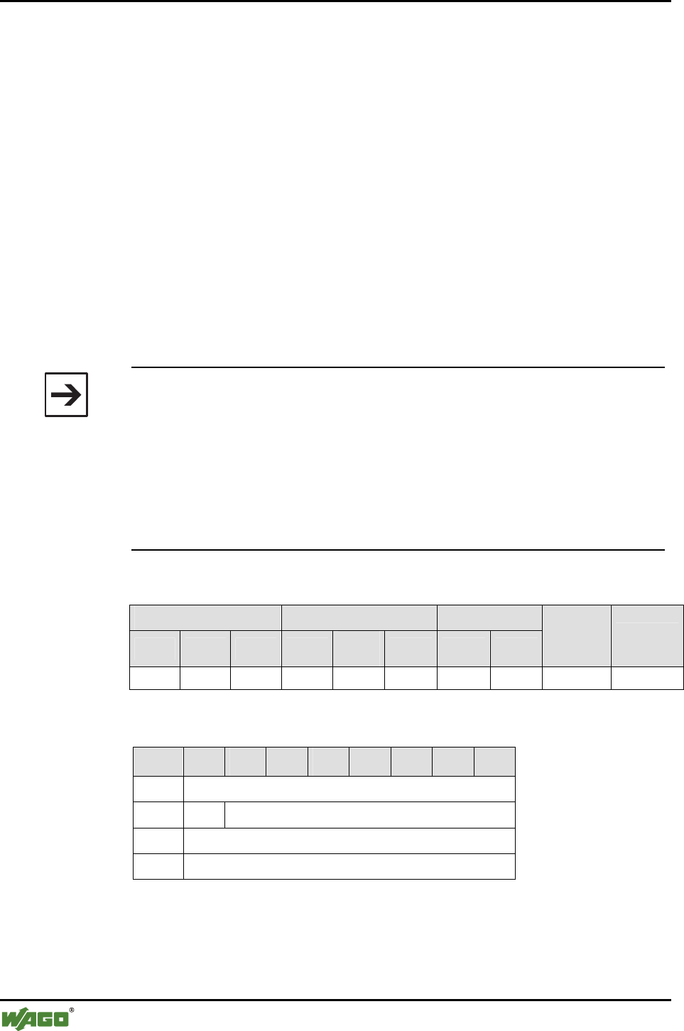
164 • Appendix
Mailbox Command References
WAGO-I/O-SYSTEM 750
I/O Modules
6.3.5.34 Set Time Settings - Between Two Attempts to Establish a Connection
(SetReconnectionTimePeriod, 0x8B)
This command sets the waiting time for the master between two attempts be-
fore attempting to establish a new connection with a slave. The settings do not
take effect until the module is switched over to master mode.
When establishing a network in communication mode, the master first at-
tempts to connect all authorized slaves. If this does not succeed, it begins the
data exchange, starting with the devices that could be connected. It then
searches again for the devices originally not found within the configured time
interval. A similar scenario applies for the failure of slaves; in this case, the
master first attempts to reconnect immediately and repeats these attempts pe-
riodically if it does not succeed immediately. In communication mode,
WAGO Bluetooth® modules are continually attempting to connect to each
other.
Note
During connection establishment to slaves, the master is not available for
data exchange. If authorized slaves have failed permanently, the remaining
network members experience communication interruption times within the
time interval of the "ReconnectionTimePeriod" until the failed device is
ready again. In the real-time profile, WAGO devices provide information on
such interruption times through the cyclical and acyclical diagnostic function.
For time-critical applications, it is possible to temporarily "eject" failed
slaves by applying the function "UnbindRemoteDevice" to them.
Conditions
Mailbox size Operating mode/profile Device role
6 12 18 Config. Real-
time Ad hoc Master Slave
Save
config. Restart
● ● ● ● - - ● ● - -
Request
Byte 27 26 25 24 23 22 21 20
0 MBX_SETRECONNECTIONTIMEPERIOD
1 T -
2 MBX_RECONNECTTIME (LSB)
3 MBX_RECONNECTTIME (MSB)

Appendix • 165
Mailbox Command References
WAGO-I/O-SYSTEM 750
I/O Modules
Arguments
Parameter Value Description
MBX_RECONNECTTIME Time in seconds Minimum time in seconds between two at-
tempts to re-establish a connection when the
previous attempt has failed.
Response
Byte 27 26 25 24 23 22 21 20
0 MBX_SETRECONNECTIONTIMEPERIOD
1 T MBX_RESULT
Return values
Parameter Value Description
- - -
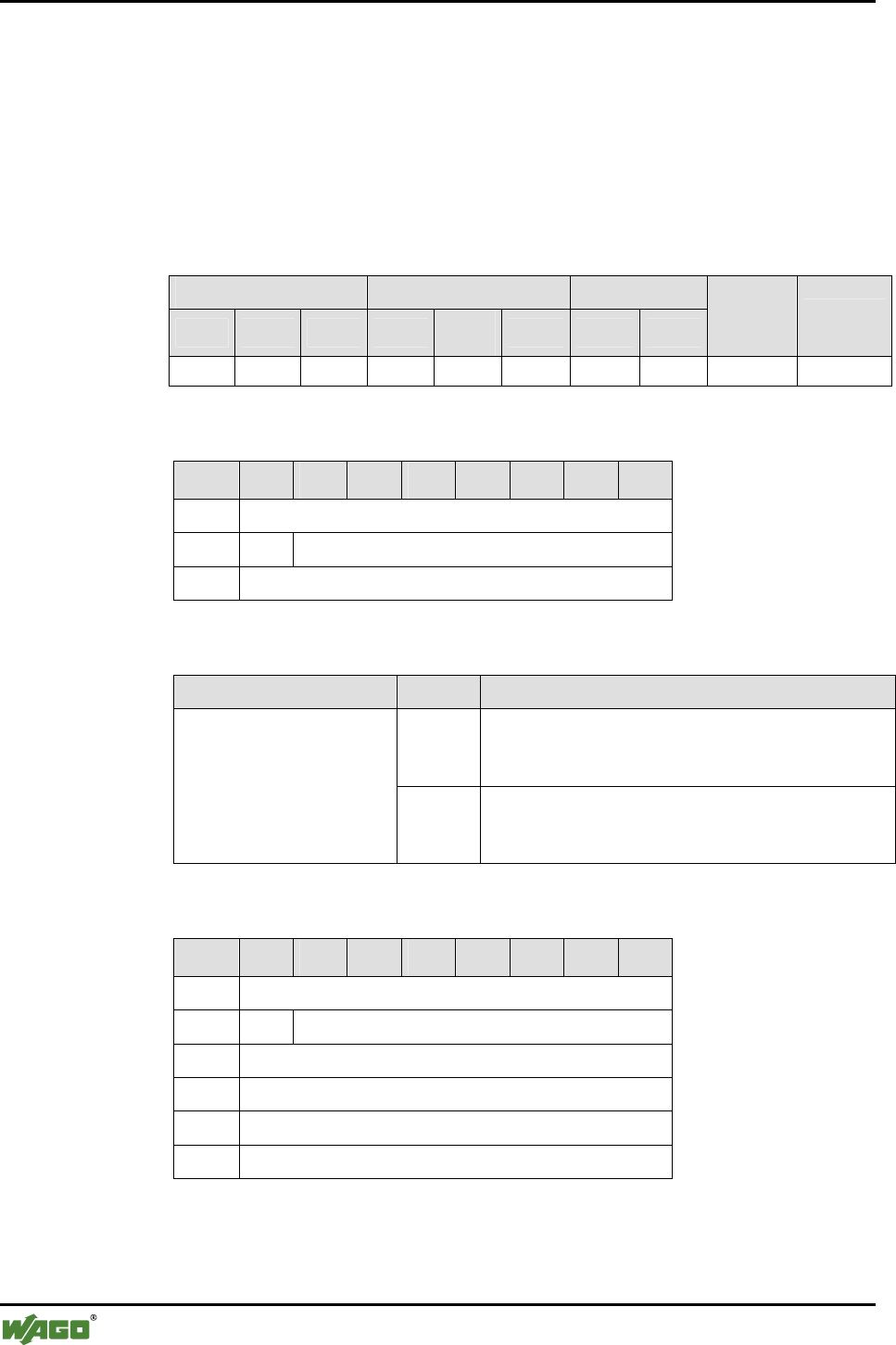
166 • Appendix
Mailbox Command References
WAGO-I/O-SYSTEM 750
I/O Modules
6.3.5.35 Read the User-Friendly Name of an Authorized Device (GetUser-
friendlyName, 0x8C)
This query can read the user-friendly name to an entry in the list of authorized
devices. If the name is too long for the actual size of the mailbox, then the first
(mailbox size - 3) characters are given out. The actual length of the name re-
turns the value of MBX_NAME_LENGTH.
Conditions
Mailbox size Operating mode/profile Device role
6 12 18 Config. Real-
time Ad hoc Master Slave
Save
config. Restart
(●) (●) ● ● ● ● ● ● - -
Request
Byte 27 26 25 24 23 22 21 20
0 MBX_GETUSERFRIENLYNAME
1 T -
2 MBX_TARGET_TABLE_AND_INDEX
Arguments
Parameter Value Description
Bit 0…3 Table Index
Index 0...6 for WAGO devices of slots 1...7
Index 0...5 for external devices of slots 8…12
MBX_TARGET_TABLE_
AND_INDEX
Bit 4…7 Target table
"2" for WAGO_DEVICE (slots 1...7)
"1" for EXTERNAL_DEVICE (slots 8…12)
Response
Byte 27 26 25 24 23 22 21 20
0 MBX_GETLOCALDEVICENAME
1 T MBX_RESULT
2 MBX_NAME_LENGTH
3 CHAR1
... ...
17 CHAR15

Appendix • 167
Mailbox Command References
WAGO-I/O-SYSTEM 750
I/O Modules
Return values
Parameter Value Description
MBX_CMD_OUT_OF_RANGE An index greater than 6 was
used
MBX_RESULT
MBX_CMD_INVALID_ARG No valid target table has been
chosen.
MBX_NAME_LENGTH [0…15] Number of characters of the
complete name
CHARn [0...255] Characters of the device name
in ASCII code
Example: "ABC"
A = CHAR1 = 0x41
B = CHAR2 = 0x42
C = CHAR3 = 0x43
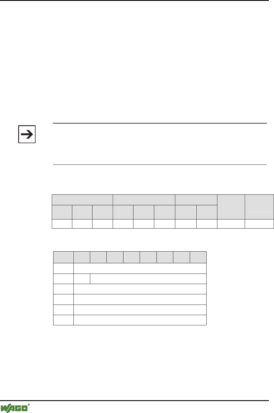
168 • Appendix
Mailbox Command References
WAGO-I/O-SYSTEM 750
I/O Modules
6.3.5.36 Write the User-Friendly Name of an Authorized Device (SetUserfriendly-
Name, 0x8D)
This command adds any alias to an entry in the list of authorized devices. This
name allows the user to give an intuitive name to the relevant removed
(remote) device, such as "Pump_001", "Gate4" or "Bus node_002". This does
not impact the Bluetooth device name of the remote device, as the alias is
stored in the local device.
By converting to ASCII characters, the name is simple to read and facilitates
the administration of the Bluetooth® device.
The name can be a maximum of (mailbox size - 3) characters long. If the name
does not completely fill up the mailbox, it ends with the first null byte.
Note
The name entry is independent of the entered device (MAC-ID). The user-
friendly name has no direct relation to the Bluetooth® name of the remote
device that can be read with "GetRemoteDeviceName". Characters following
a null byte are ignored.
Conditions
Mailbox size Operating mode/profile Device role
6 12 18 Config. Real-
time Ad hoc Master Slave
Save
config. Restart
(●) (●) ● ● - - ● ● - -
Request
Byte 27 26 25 24 23 22 21 20
0 MBX_GETUSERFRIENLYNAME
1 T -
2 MBX_TARGET_TABLE_AND_INDEX
3 CHAR1
... ...
17 CHAR15
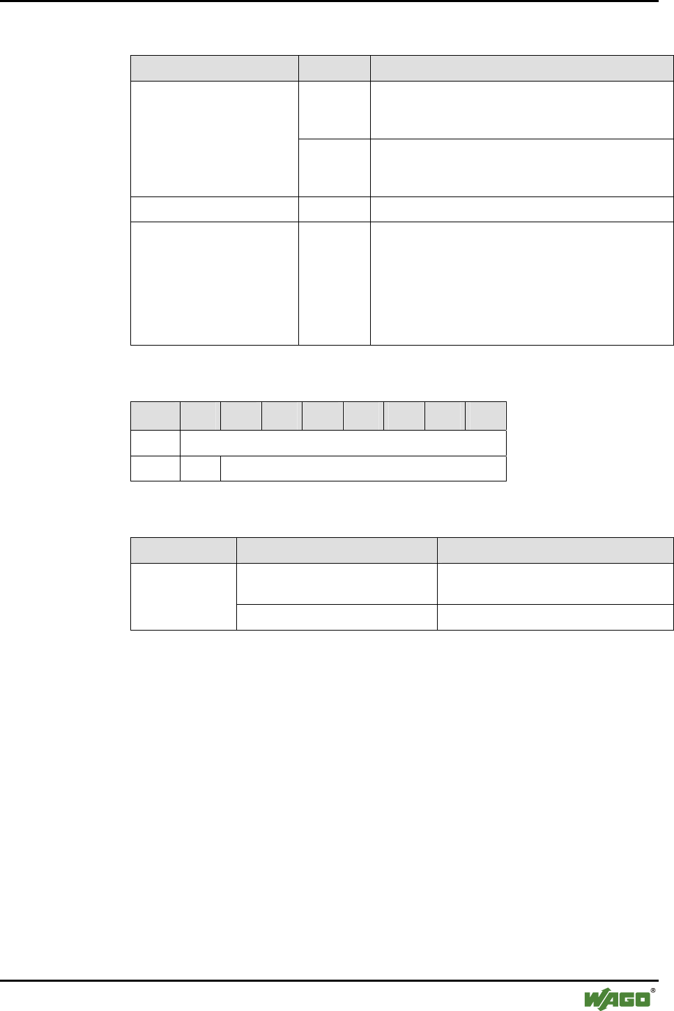
Appendix • 169
Mailbox Command References
WAGO-I/O-SYSTEM 750
I/O Modules
Arguments
Parameter Value Description
Bit 0…3 Table Index
Index 0...6 for WAGO devices of slots 1...7
Index 0...5 for external devices of slots 8...12
MBX_TARGET_TABLE_
AND_INDEX
Bit 4…7 Target table
"2" for WAGO_DEVICE (slots 1...7)
"1" for EXTERNAL_DEVICE (slots 8...12)
MBX_NAME_LENGTH [0...15] Number of characters of the complete name
CHARn [0...255] Characters of the device name in ASCII code
0x0 close the string
Example: "ABC"
A = CHAR1 = 0x41
B = CHAR2 = 0x42
C = CHAR3 = 0x43
End of the name = CHAR4 = 0x00
Response
Byte 27 26 25 24 23 22 21 20
0 MBX_GETLOCALDEVICENAME
1 T MBX_RESULT
Return values
Parameter Value Description
MBX_CMD_OUT_OF_RANGE An index > 6 (for WAGO devices) and
> 5 (for external devices) were selected.
MBX_RESULT
MBX_CMD_INVALID_ARG No valid target table chosen.
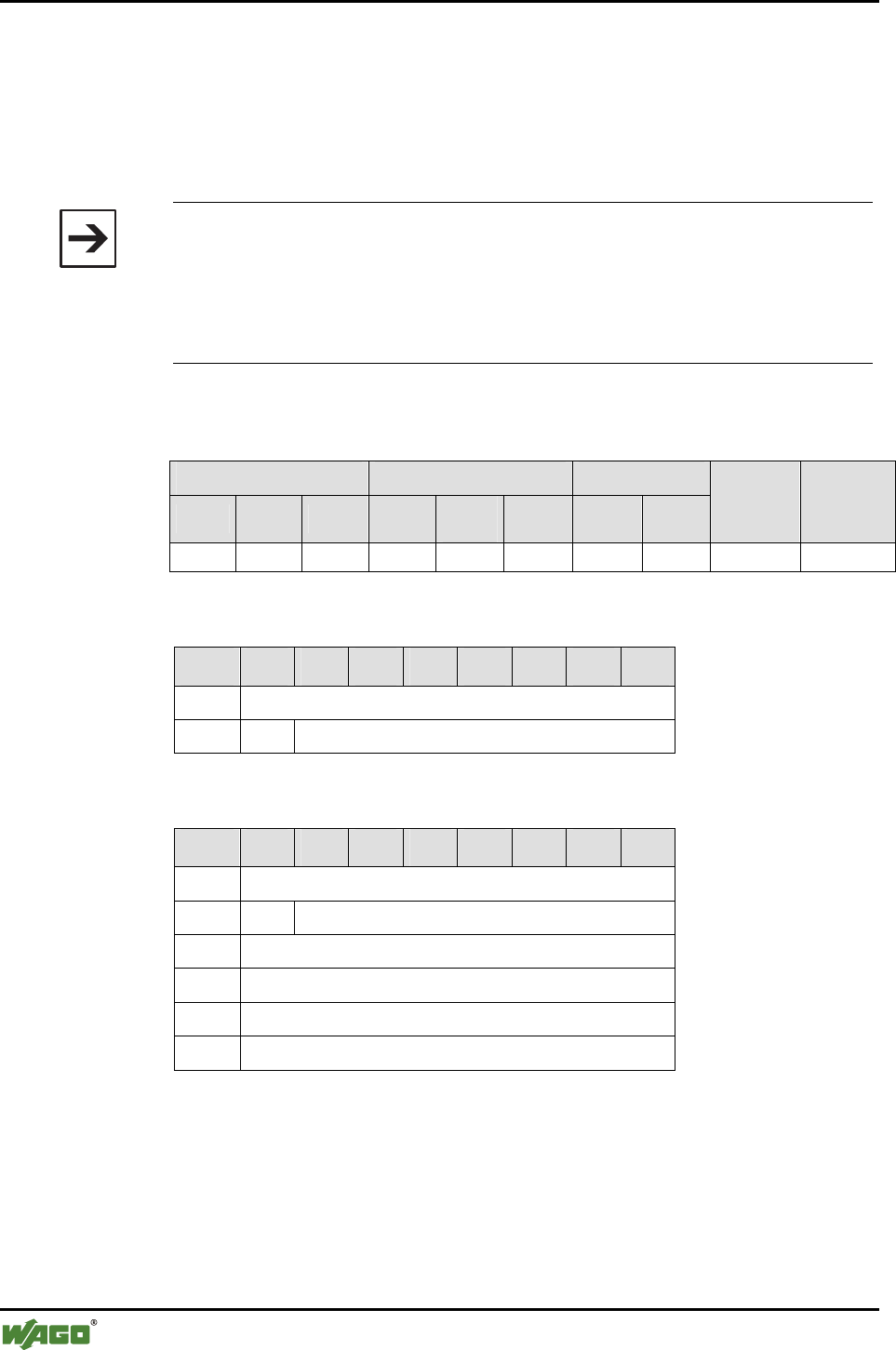
170 • Appendix
Mailbox Command References
WAGO-I/O-SYSTEM 750
I/O Modules
6.3.6 Diagnostics
6.3.6.1 Read Status of the Local Bus Module (GetLocalDeviceStatus, 0xD0)
Call up returns the type of bus module, operating mode, operating profile and
a general diagnostic status.
Note
The bus module type is set via "SetLocalDeviceRole" commands (see Ap-
pendix 6.3.5.21) and read back via "GetLocalDeviceRole" (see Appendix
6.3.5.20). Both the operation mode and operation profile are set via "SetLo-
calOperationMode"“ (see Appendix 6.3.5.11) and read back via "GetLoca-
lOperationMode" (see Appendix 6.3.5.10).
Conditions
Mailbox size Operating mode/profile Device role
6 12 18 Config. Real-
time Ad hoc Master Slave
Save
config. Restart
● ● ● ● ● ● ● ● - -
Request
Byte 27 26 25 24 23 22 21 20
0 MBX_GETLOCALDEVICESTATUS
1 T -
Response
Byte 27 26 25 24 23 22 21 20
0 MBX_GETLOCALDEVICESTATUS
1 T MBX_RESULT
2 MBX_DEVICE_ROLE
3 MBX_OPMODE_ID
4 MBX_COMMROFILE_ID
5 MBX_DIAGNOSTIC_STATE

Appendix • 171
Mailbox Command References
WAGO-I/O-SYSTEM 750
I/O Modules
Return values
Parameter Value Description
MBX_ROLE_COORDINATOR
(0x01)
Device role of master
reserved (0x02) Reserved
MBX_DEVICE_ROLE
MBX_ROLE_ENDDEVICE (0x03) Device role of slave
MBX_CM_OPMODE_CONF
(0x01)
Configuration mode MBX_OPMODE_ID
MBX_CM_OPMODE_COMM
(0x02)
Communication mode
MBX_CM_OPPROFILE_REALTIME
(0x01)
Real-time profile
(communication mode)
MBX_CM_OPPROFILE_ADHOC
(0x03)
Ad hoc profile
(communication mode)
MBX_COMMROFILE
_ID
MBX_CM_OPPROFILE_CONFIG
(0x02)
Configuration profile
(configuration mode)
OK 0x00 No error, no warning
MBX_WARNING (0x01) Warning. Details query
necessary
MBX_ERROR (0x02) General error, details
query necessary
MBX_DIAGNOSTIC
_STATE
MBX_CRITICAL_ERROR (0x04) Critical error, details query
necessary
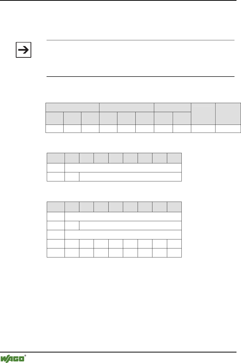
172 • Appendix
Mailbox Command References
WAGO-I/O-SYSTEM 750
I/O Modules
6.3.6.2 Read Status of the Wireless Network (GetNetworkStatus, 0xD1)
Call up returns information on the status of the wireless network. Information
on WAGO devices and external devices is recorded.
Note
Because no wireless connection is established in configuration mode,
MBX_NETWORK_FAILED (0x01) is always returned in this case. Since no
connections are established in configuration mode, the other arguments of
this command in this mode always deliver "0".
Conditions
Mailbox size Operating mode/profile Device role
6 12 18 Config. Real-
time Ad hoc Master Slave
Save
config. Restart
● ● ● ● ● ● ● ● - -
Request
Byte 27 26 25 24 23 22 21 20
0 MBX_GETNETWORKSTATUS
1 T -
Response
Byte 27 26 25 24 23 22 21 20
0 MBX_GETNETWORKSTATUS
1 T MBX_RESULT
2 MBX_NETWORK_STATE
3 W7 W6 W5 W4 W3 W2 W1 W0
4 E7 E6 E5 E4 E3 E2 E1 E0
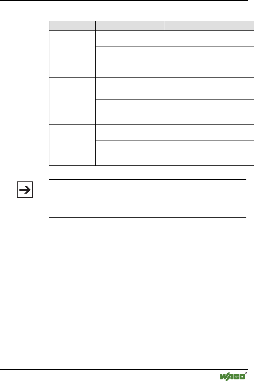
Appendix • 173
Mailbox Command References
WAGO-I/O-SYSTEM 750
I/O Modules
Return values
Parameter Value Description
MBX_NETWORK_FAILED
(0x01)
Configured network not established
(e.g., in configuration mode)
MBX_NETWORK_OK
(0x02)
Configured network successfully estab-
lished.
MBX_NETWORK
_STATE
MBX_NETWORK_
INCONSISTENT (0x03)
At least one, but not all, configured
connections could be established.
Assigned bit = 1 Assigned device from the table of
WAGO devices is linked and con-
nected.
W0 …W6
Assigned bit = 0 Assigned device from the table of
WAGO devices is not connected.
W7 0 Reserved
Assigned bit = 1 Assigned device from the table of ex-
ternal devices is linked and connected.
E0...E5
Assigned bit = 0 Assigned device from the table of ex-
ternal devices is not connected.
E6, E7 0 Reserved
Note
W0 to W6 correspond to WAGO devices 0x20 to 0x26 with
MBX_TARGET_TABLE_AND_INDEX.
E0 to E5 correspond to external devices 0x10 to 0x16 with
MBX_TARGET_TABLE_AND_INDEX.
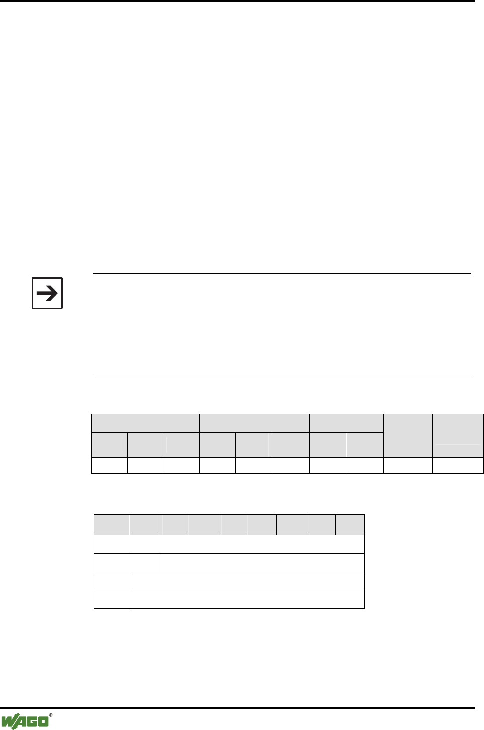
174 • Appendix
Mailbox Command References
WAGO-I/O-SYSTEM 750
I/O Modules
6.3.6.3 Read Diagnostic Information (GetStatusMessage, 0xD2)
The command returns diagnostic information on occurring errors and warn-
ings from the local bus module.
When querying, a concrete object identification MBX_OBJECT_ID must be
indicated. The response then always contains the same MBX_OBJECT_ID
plus a defined status report MBX_STATE_MESSAGE. If the object identifi-
cation remains unknown, the system returns the information byte for executing
the command MBX_CMD_RESULT and the value
MBX_CMD_INVALID_ARG.
Each defined MBX_OBJECT_ID is always uniquely assigned a current status
report (usually "OK"). If an event occurs, the status report is changed each
time to mirror the most recently occurring event. The status report of an indi-
vidual MBX_OBJECT_ID is always overwritten with the next more recent
event as long as it is not "OK". The prioritization of error message before
warning message must always be observed.
Note
In the cyclical status report (C/S byte, LED activation), errors/warnings are
only displayed as long as the disturbed status lasts. The status report, on the
other hand, remains until it is overwritten (new message for the same Objec-
tID occurs).
Errors always have a higher priority than warnings in the display.
Only the status of WAGO devices is recorded.
Conditions
Mailbox size Operating mode/profile Device role
6 12 18 Config. Real-
time Ad hoc Master Slave
Save
config. Restart
● ● ● ● ● ● ● ● - -
Request
Byte 27 26 25 24 23 22 21 20
0 MBX_GETSTATUSMESSAGE
1 T -
2 MBX_OBJECT_ID (LSB)
3 MBX_OBJECT_ID_LO
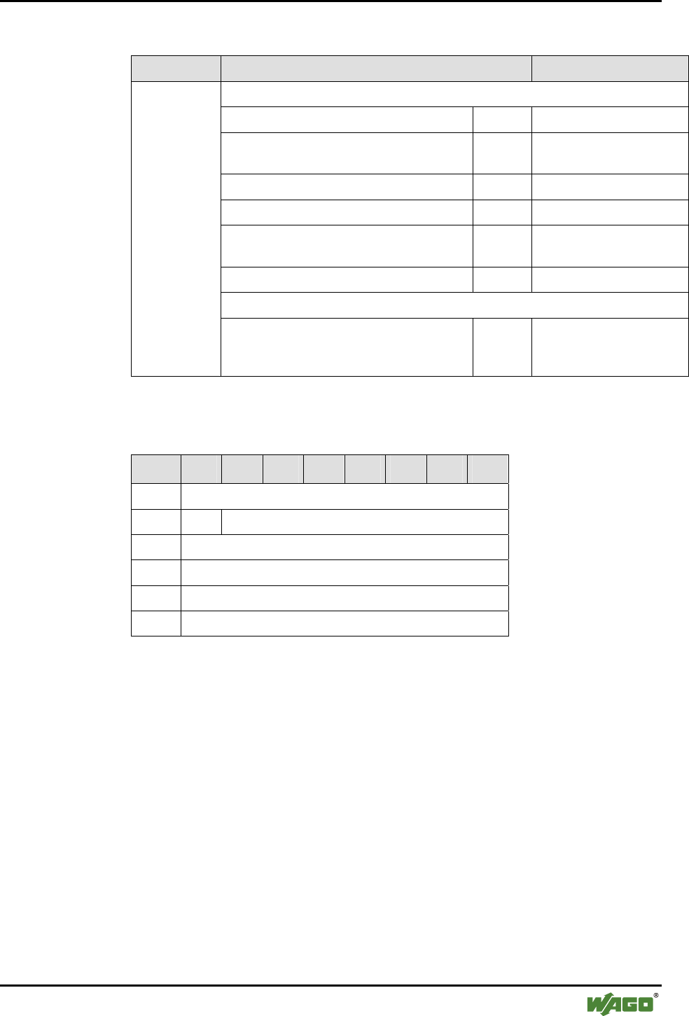
Appendix • 175
Mailbox Command References
WAGO-I/O-SYSTEM 750
I/O Modules
Arguments
Parameter Value Description
MBX_OBJECTID_GROUP_MASK 0xF000
MBX_OBJECTID_GROUP_SYSTEM 0x0000 Status of whole system
MBX_OBJECTID_GROUP_WIRELESS 0x1000 Status of wireless con-
nections
MBX_OBJECTID_GROUP_TIMING 0x2000 Status of time monitoring
MBX_OBJECTID_GROUP_PA 0x3000 Status of process image
MBX_OBJECTID_GROUP_ISC 0x4000 Status of intersystem
communication
MBX_OBJECTID_GROUP_CONFIG 0x5000 Status of configuration
MBX_OBJECTID_TARGET_MASK 0x0FFF
MBX_
OBJECT _ID
Target-ID 0x000
to
0x0007
Target object in the group
See also Appendix 6.3.6.3.1 "Establishment of the Object-ID".
Response
Byte 27 26 25 24 23 22 21 20
0 MBX_GETSTATUSMESSAGE
1 T MBX_RESULT
2 MBX_OBJECT_ID (LSB)
MBX_OBJECT_ID (MSB)
MBX_STATE_MESSAGE (LSB)
MBX_STATE_MESSAGE (MSB)

176 • Appendix
Mailbox Command References
WAGO-I/O-SYSTEM 750
I/O Modules
Return values
Parameter Value Description
MBX_CMD_DENIED_NOT_
IMPLEMENTED
Non-implemented
MBX_OBJECT_ID
MBX_CMD_DENIED_
BUSY
Another MBX command ac-
tively being processed
MBX_CMD_
RESULT
MBX_CMD_INVALID_ARG Invalid object ID
MBX_
OBJECT _ID
See Appendix 6.3.6.3.1, Establishment of the Object ID.
MBX_STATE_OK 0x0000 No error
MBX_STATE_OK_CONFIG_CHANGED 0x0001 Configuration
changed, but not yet
saved
Error messages
MBX_STATE_ERROR_UNSPECIFIED 0x1000 Not specified
MBX_STATE_ERROR_WATCHDOG 0x1001 Watchdog
MBX_STATE_ERROR_CREATE_LINK 0x1002 Connection error
MBX_STATE_ERROR_LOST_LINK 0x1003 Connection inter-
rupted
MBX_STATE_ERROR_PASIZE_WRONG 0x1004 Process image defec-
tive
MBX_STATE_ERROR_SYSTEMBUS_JAM 0x1005 SPI overloaded
MBX_STATE_ERROR_SYSTEMBUS
_INTERRUPTED
0x1006 Interruption in SPI
communication
MBX_STATE_ERROR_MAILBOX_
COMMAND
0x1007 Error in the mailbox
communication
MBX_STATE_ERROR_NETWORK_
CONFIG
0x1008 Error in the network
configuration
Warning messages
MBX_STATE_WARNING_UNSPECIFIED 0x2000 Not specified
MBX_STATE_WARNING_WATCHDOG 0x2001 Watchdog
MBX_STATE_WARNING_LESSTHEN_54_
CHANNELS
0x2002 Less than 54 channels
available
MBX_STATE_WARNING_LESSTHEN_39_
CHANNELS
0x2003 Less than 39 channels
available
MBX_STATE_WARNING_BER_MEDIUM 0x2004 BER is moderate
MBX_STATE_WARNING_BER_HIGH 0x2005 BER is high
MBX_STATE
_MESSAGE
MBX_STATE_WARNING_REMOTE_
MAILBOX
0x2006 A remote mailbox is
active; data in the
process image may be
obsolete.

Appendix • 177
Mailbox Command References
WAGO-I/O-SYSTEM 750
I/O Modules
6.3.6.3.1 Structure of the Object ID
The object ID is composed of a group ID and a target ID. The group ID identi-
fies the functional group for which the status is to be queried. The target ID
indicates the target for which the status is to be queried. Either all existing
connections (0x0000) or individual connections (0x0001 to 0x0007) can be
chosen. A maximum of one connection exists in one slave; therefore, only the
target IDs 0x0000 and 0x0001 are valid in this case as well. For a master, the
target IDs 0x0000 and 0x0007 are valid. If the maximum of 7 devices have
been configured, the query of a target ID for which no device has been config-
ured returns the value MBX_STATE_ERROR_UNSPECIFIED (0x1000). If a
connection has been configured but could not be established, the query of the
corresponding target ID always returns the value
MBX_STATE_ERROR_CREATE_LINK (ox1002).
In order to calculate the group ID and target ID from an existing object ID,
and vice versa, the following logical links must be used:
Group_ID = Object_ID ∧ 0xF000
Target_ID = Object_ID ∧ 0x0FFF
Object_ID = Group_ID ∨ Target_ID
Group
Group ID
Target-
ID
Description
0x0000 0x0000 The query of the group status always returns MBX_STATE_OK.
An error in the overall system indicates module failure.
0x0000 If not all devices are connected or if the bus module is in the
configuration mode, MBX_STATUS_ERROR_UNSPECIFIED
is returned as the group status, otherwise MBX_STATE_OK.
Wireless (status
of the wireless
connections),
0x1000 slave:
0x0001
master:
0x0001
to
0x0007
If no device is linked for the corresponding table space,
MBX_STATE_OK is always returned.
For existing connections, the following warnings can be issued
for connection quality:
- MBX_STATE_WARNING_BER_HIGH
- MBX_STATE_WARNING_BER_MEDIUM
- MBX_STATE_WARNING_LESSTHEN_39_CHANNELS
- MBX_STATE_WARNING_LESSTHEN_54_CHANNELS
A master can deliver additional information on the connection
status:
- MBX_STATE_OK
if the corresponding slave is connected or has just connected
- MBX_STATE_ERROR_CREATE_LINK
if the slave could not be connected but further attempts to
connect are performed (device is configured but cannot
be reached)

178 • Appendix
Mailbox Command References
WAGO-I/O-SYSTEM 750
I/O Modules
Group
Group ID
Target-
ID
Description
Time monitoring
0x2000
0x0000
and
slave:
0x0001
master:
0x0001
to
0x0007
For connected WAGO devices:
- MBX_STATE_ERROR_WATCHDOG - the time since the
last packet is greater than 60 x (number of active wireless
channels + 2 ms)
- MBX_STATE_WARNING_WATCHDOG - the time since
the last packet is greater than 20 x (number of active wireless
channels + 2 ms)
- MBX_STATE_OK - the time since the last packet is less than
20 x (number of active wireless channels + 2 ms)
For connected external devices:
- Always MBX_STATE_OK
0x0000 - MBX_STATE_ERROR_PASIZE_WRONG
the sum of all preset cut offs is greater than the size of the
process image minus 2
- MBX_STATE_WARNING_REMOTE_MAILBOX
the mailbox is active in at least one remote device
Process image
0x3000
0x0001
until
0x0007
- MBX_STATE_ERROR_PASIZE_WRONG
the preset cut off is larger than the size of the process image
minus 2
- MBX_STATE_WARNING_REMOTE_MAILBOX
the mailbox is active in the remote device; the data in the
process image may be obsolete
Intersystem
communication
0x4000
- Reserved
Configuration
0x5000
0x0000 The group status returns
MBX_STATE_OK_CONFIG_CHANGED if the configuration
has changed; otherwise, MBX_STATE_OK
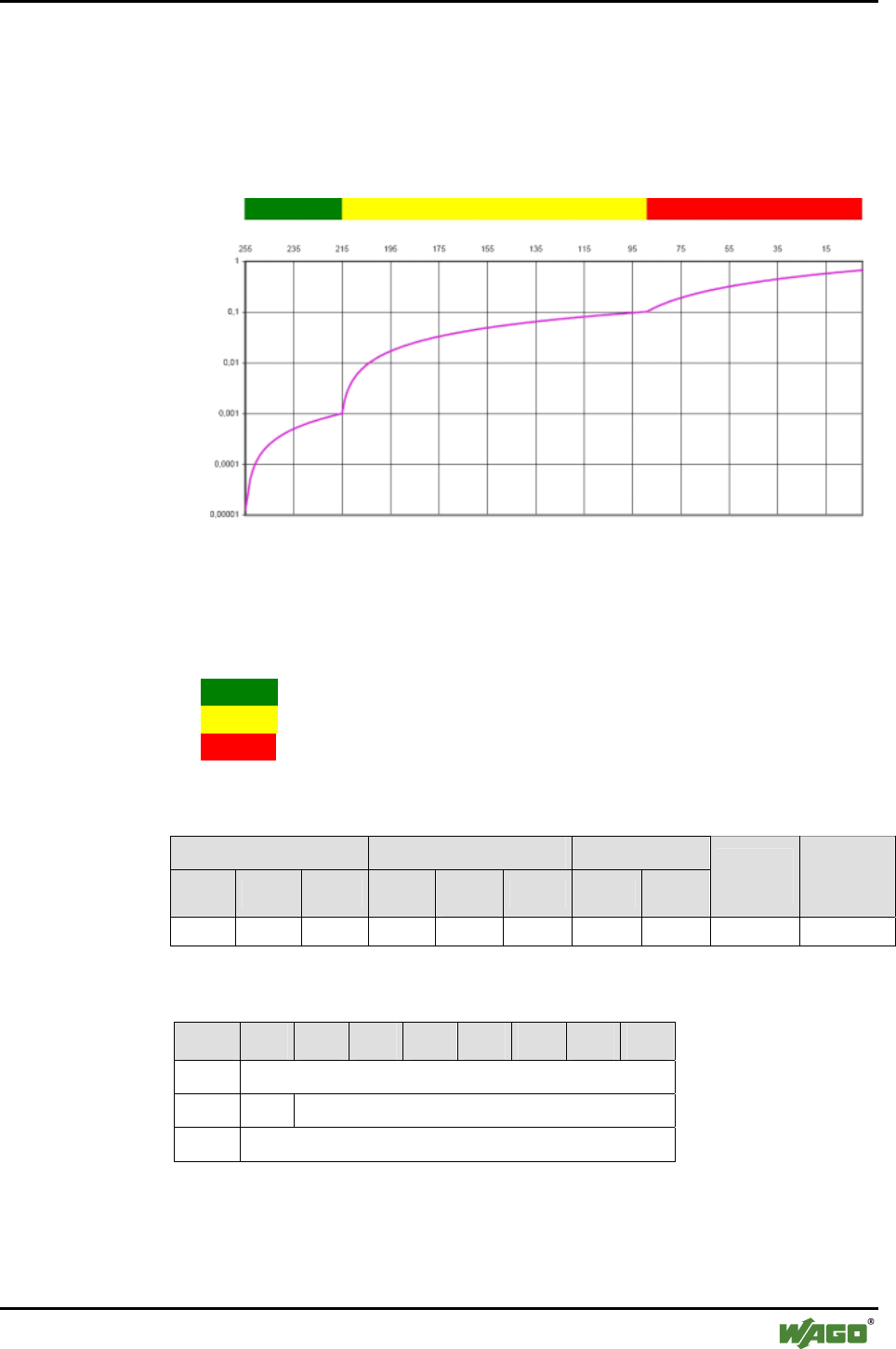
Appendix • 179
Mailbox Command References
WAGO-I/O-SYSTEM 750
I/O Modules
6.3.6.4 Read Connection Quality (GetLinkQuality, 0xD5)
Connection quality ("Link Quality" LQ) returns the bit error rate of the wire-
less connection. The conversion of an LQ value to the current bit error rate
can take place with the following characteristics:
Bit error rate
Connection quality
Figure 42: Connection between connection quality and bit error rate as well as LED signaling
g064468x
The connection quality (see bars over the table) is indicated by LEDs:
• Green:. indicates a low bit error rate of < 10-3
• Yellow: indicates a bit error rate ranging from 10-2 to 10-3
• Red:. .. indicates a bad transmission channel with a bit error rate of < 10-2
Conditions
Mailbox size Operating mode/profile Device role
6 12 18 Config. Real-
time Ad hoc Master Slave
Save
config. Restart
● ● ● - ● ● ● ● - -
Request
Byte 27 26 25 24 23 22 21 20
0 MBX_GETLINKQUALITY
1 T -
2 MBX_TARGET_TABLE_AND_INDEX

180 • Appendix
Mailbox Command References
WAGO-I/O-SYSTEM 750
I/O Modules
Arguments
Parameter Value Description
Bit 0…3 Table Index
Index 0...6 for WAGO devices of slots 1...7
Index 0...5 for external devices of slots 8...12
MBX_TARGET_TABLE_
AND_INDEX
Bit 4…7 Target table
"2" for WAGO_DEVICE (slots 1…7)
"1" for EXTERNAL_DEVICE (slots 8…12)
Response
Byte 27 26 25 24 23 22 21 20
0 MBX_GETLINKQUALITY
1 T MBX_RESULT
2 MBX_LQ_VALUE
Return values
Parameter Value Description
MBX_CMD_OUT_OF_RANGE Too large of an index was used.
MBX_CMD_GENERAL_ERROR The device is not connected.
MBX_RESULT
MBX_CMD_INVALID_ARG The device is not connected or no
valid target table was chosen.
MBX_LQ_VALUE [0….255] Value of the connection quality for
the requested connection
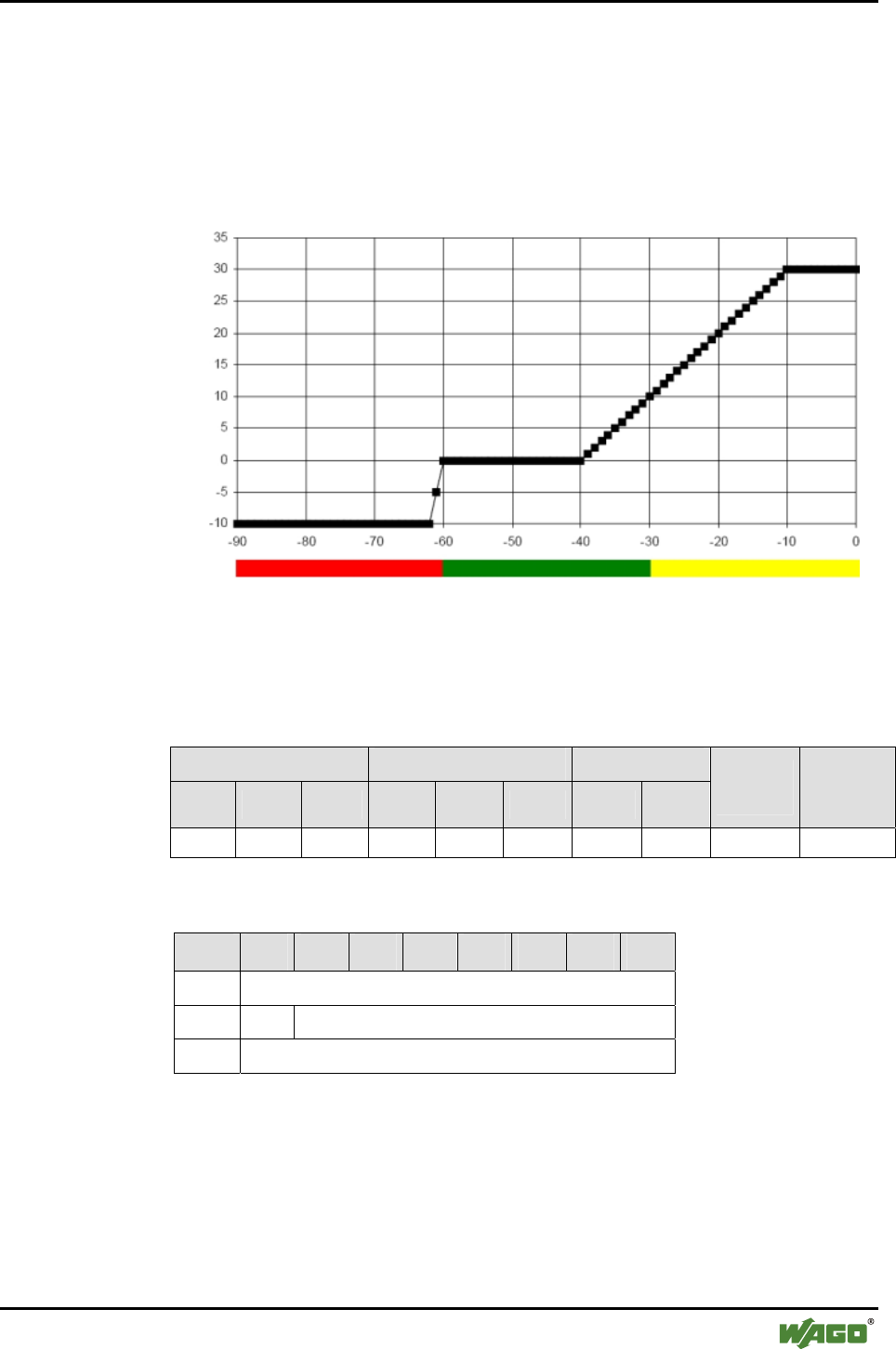
Appendix • 181
Mailbox Command References
WAGO-I/O-SYSTEM 750
I/O Modules
6.3.6.5 Read Signal Strength for a Connection (GetLinkSignalStrength, 0xD7)
The RSSI value indicates possible overmodulation of the Bluetooth® recipient.
It returns "0" if the strength of the received signal lies within the tolerance
range. If the received signal is stronger than the upper limit of the tolerance
range, a value > "0" is returned; if the received signal is weaker than the lower
limit, a value < "0" is returned.
RSSI
Incoming signal strength (dBm)
Figure 43: Connection between RSSI value and LED color (see bars below the table) g064469x
Conditions
Mailbox size Operating mode/profile Device role
6 12 18 Config. Real-
time Ad hoc Master Slave
Save
config. Restart
● ● ● - ● ● ● ● - -
Request
Byte 27 26 25 24 23 22 21 20
0 MBX_GETLINKSIGNALSTRENGTH
1 T -
2 MBX_TARGET_TABLE_AND_INDEX
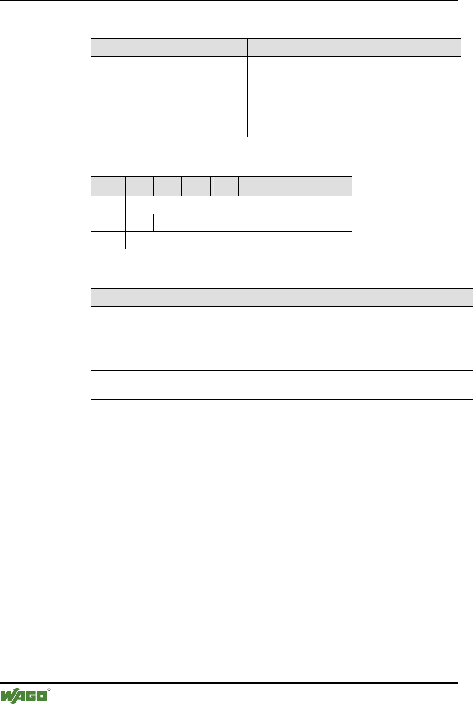
182 • Appendix
Mailbox Command References
WAGO-I/O-SYSTEM 750
I/O Modules
Arguments
Parameter Value Description
Bit 0…3 Table Index
Index 0...6 for WAGO devices of slots 1...7
Index 0…5 for external devices of slots 8...12
MBX_TARGET_TABLE_
AND_INDEX
Bit 4…7 Target table
"2" for WAGO_DEVICE (slots 1...7)
"1" for EXTERNAL_DEVICE (slots 8...12)
Response
Byte 27 26 25 24 23 22 21 20
0 MBX_GETLINKSIGNALSTRENGTH
1 T MBX_RESULT
2 MBX_RSSI_VALUE
Return values
Parameter Value Description
MBX_CMD_OUT_OF_RANGE Too large of an index was used.
MBX_CMD_GENERAL_ERROR The device is not connected.
MBX_RESULT
MBX_CMD_INVALID_ARG The device is not connected or no valid
target table was chosen.
MBX_RSSI_
VALUE
-128…127 (two's complement) RSSI value for the requested connec-
tion

Appendix • 183
Mailbox Command References
WAGO-I/O-SYSTEM 750
I/O Modules
6.3.6.6 Read Available Hopping Channels (GetAvailableChannelMap, 0xD8)
Call up returns information on the status of the environment (i.e., the status of
the wireless medium) for a connection channel. For Bluetooth®, the channels
available for hopping are indicated. There are 79 channels with 1 MHz avail-
able. The channels are numbered serially from 0 through 78. The frequency of
each channel is based on the channel number:
Frequency of the channel = 2402 + channel number MHz
The WAGO Bluetooth® module supports AFH (adaptive frequency hopping).
If individual frequency ranges are recognized as defective (for example, if
other wireless technologies with higher signal strength in this range are send-
ing), the corresponding channels of its own transmission are excluded. This
reduces interference and improves the connection quality for the Bluetooth®
network, as well as for the third-party system. A positive side effect is the pos-
sibility of making connections through third-party activity in the 2.4 GHz ISM
band using the list of the channels masked in this manner. The rule of thumb
is: The greater the number of channels available for hopping, the better the
status of the wireless medium.
Conditions
Mailbox size Operating mode/profile Device role
6 12 18 Config. Real-
time Ad hoc Master Slave
Save
config. Restart
- ● ● - ● ● ● ● - -
Request
Byte 27 26 25 24 23 22 21 20
0 MBX_GETAVAILABLECHANNELMAP
1 T -
2 MBX_TARGET_TABLE_AND_INDEX
Arguments
Parameter Value Description
Bit 0…3 Table Index
Index 0...6 for WAGO devices of slots 1...7
Index 0...5 for external devices of slots 8...12
MBX_TARGET_TABLE_
AND_INDEX
Bit 4…7 Target table
"2" for WAGO_DEVICE (slots 1...7)
"1" for EXTERNAL_DEVICE (slots 8...12)
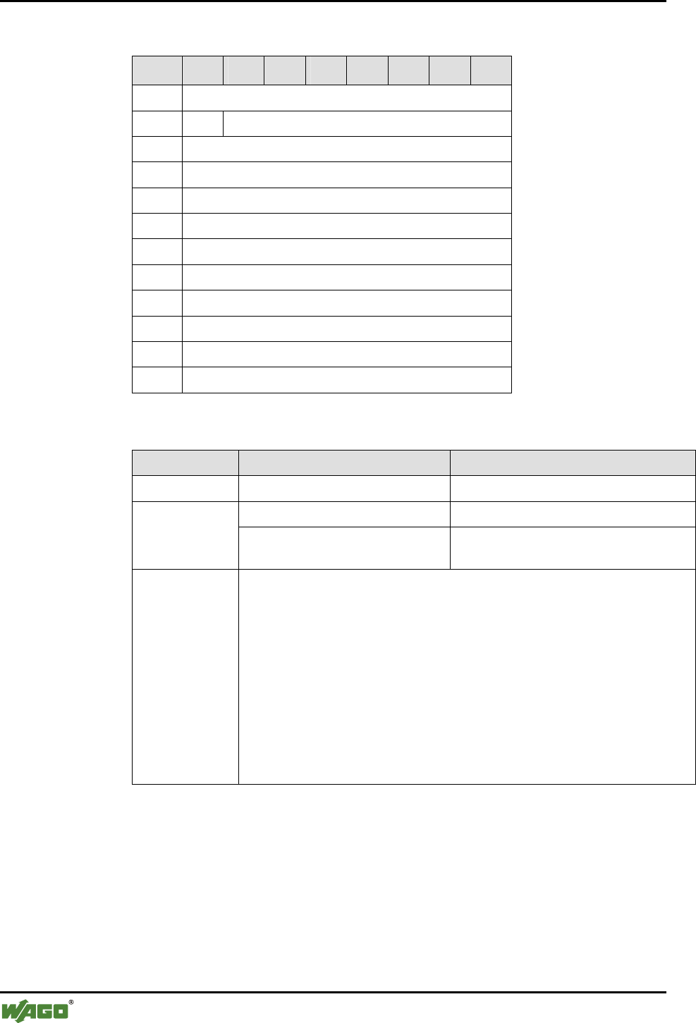
184 • Appendix
Mailbox Command References
WAGO-I/O-SYSTEM 750
I/O Modules
Response
Byte 27 26 25 24 23 22 21 20
0 MBX_GETAVAILABLECHANNELMAP
1 T MBX_RESULT
2 MBX_AFH_CHANNEL_MAP (LSB)
3 MBX_AFH_CHANNEL_MAP
4 MBX_AFH_CHANNEL_MAP
5 MBX_AFH_CHANNEL_MAP
6 MBX_AFH_CHANNEL_MAP
7 MBX_AFH_CHANNEL_MAP
8 MBX_AFH_CHANNEL_MAP
9 MBX_AFH_CHANNEL_MAP
10 MBX_AFH_CHANNEL_MAP
11 MBX_AFH_CHANNEL_MAP (MSB)
Return values
Parameter Value Description
MBX_RESULT MBX_CMD_OUT_OF_RANGE Too large of an index was used.
MBX_CMD_GENERAL_ERROR Device is not connected
MBX_CMD_INVALID_ARG The device is not connected or no valid
target table was chosen.
MBX_AFH_
CHANNEL_
MAP
Each Bluetooth®channel is represented by one bit:
Bit x = 0: channel x is not available for hopping
(because otherwise busy in the wireless medium);
Bit x = 1: channel can be used for channel hopping for the requested
connection.
Channel numbers correspond to the quality rating of the bits:
Bit 0 (bit with the lowest value) in the LSB = channel 0 (2402 MHz)
Bit 1 in the LSB = channel 1 (2403 MHz)
:
Bit 6 in the MSB = channel 78 (2480 MHz)
Bit 7 (bit with the highest value) in the MSB = channel 79 (always 0, does
not exist)
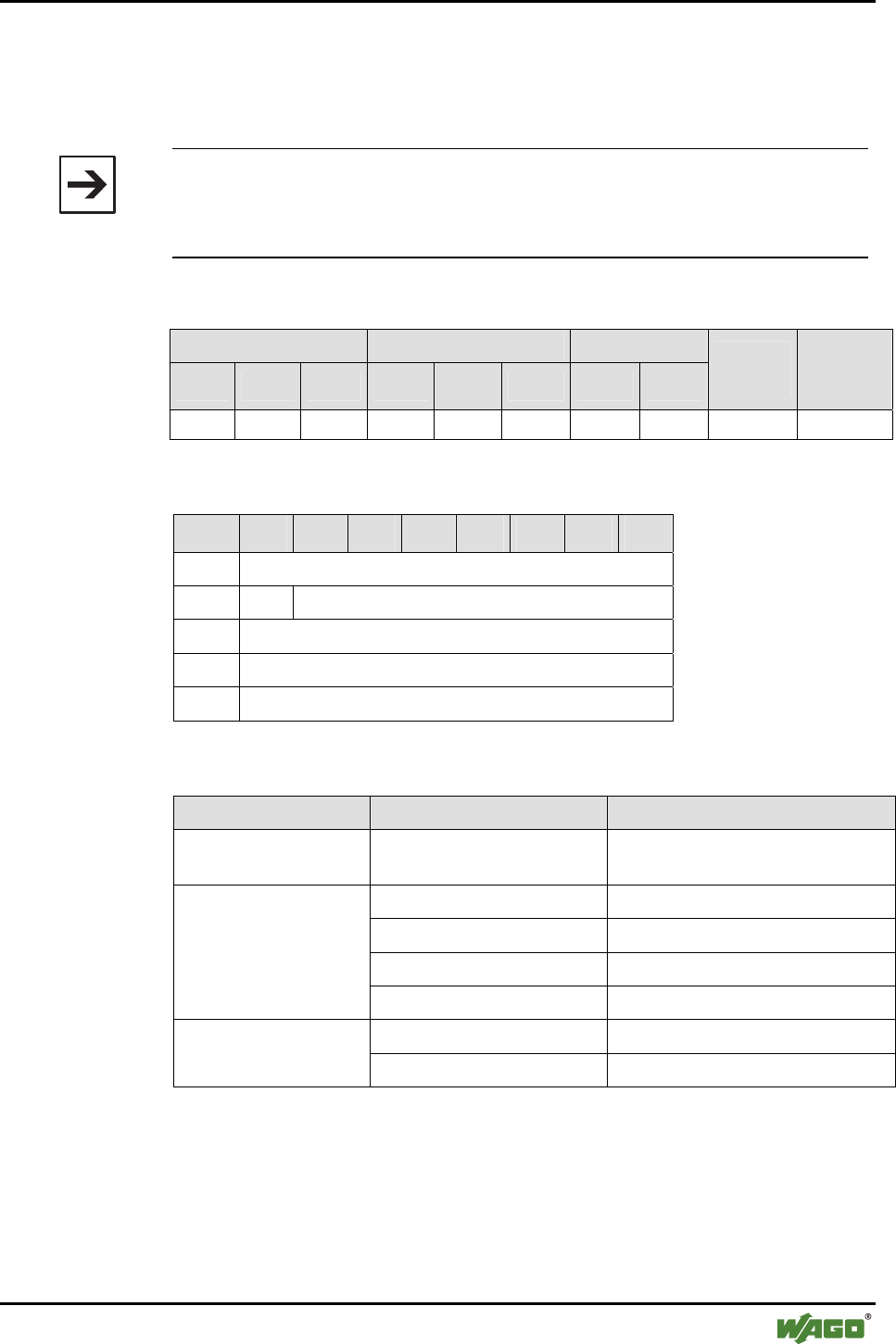
Appendix • 185
Mailbox Command References
WAGO-I/O-SYSTEM 750
I/O Modules
6.3.6.7 Set an LED (SetLED, 0xD9)
Call up sets color and blink code of a defined LED. This can be used to test
the functionality of the LED.
Note
To reinstate normal status information on the LEDs, the module must be re-
started. This can be triggered by the corresponding mailbox command or by
briefly switching off the power.
Conditions
Mailbox size Operating mode/profile Device role
6 12 18 Config. Real-
time Ad hoc Master Slave
Save
config. Restart
● ● ● ● - - ● ● - -
Request
Byte 27 26 25 24 23 22 21 20
0 MBX_SETLED
1 T -
2 MBX_LED_NUMBER
3 MBX_LED_COLOR
4 MBX_LED_BLINK
Arguments
Parameter Value Description
MBX_LED_NUMBER [0 ...7] Selection of the LED, top left LED0,
to the right of that LED1, etc.
MBX_LEDOFF (0x00) LED off
MBX_LEDRED (0x01) LED color red
MBX_LEDGREEN (0x02) LED color green
MBX_LED_COLOR
MBX_LEDYELLOW (0x03) LED color yellow
MBX_LEDSTATIC (0x00) LED will remain lit MBX_LED_BLINK
MBX_LEDBLINK (0x01) LED blinks

186 • Appendix
Mailbox Command References
WAGO-I/O-SYSTEM 750
I/O Modules
Response
Byte 27 26 25 24 23 22 21 20
0 MBX_SETLED
1 T MBX_RESULT
Return values
Parameter Value Description
MBX_CMD_OK No error occurred
MBX_CMD_DENIED_NOT_
APPLICABLE
Not available in real-time and ad-
hoc profiles
MBX_CMD_OUT_OF_RANGE An invalid LED number given.
MBX_RESULT
MBX_CMD_INVALID_ARG An invalid color or an invalid be-
havior indicated.
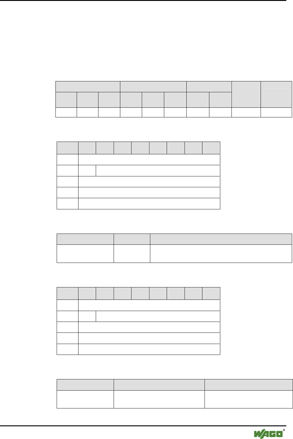
Appendix • 187
Mailbox Command References
WAGO-I/O-SYSTEM 750
I/O Modules
6.3.6.8 Mirror Mailbox for Test Purposes (MirrorMailboxCommand, 0xDA)
This command causes the module to immediately copy the full contents of the
mailbox query to the contents of the response. The command can be executed
to test the acyclic communication between the application and the local Blue-
tooth® module.
Conditions
Mailbox size Operating mode/profile Device role
6 12 18 Config.
Real-
time Ad hoc Master Slave
Save
config. Restart
● ● ● ● ● ● ● ● - -
Request
Byte 27 26 25 24 23 22 21 20
0 MBX_MIRRORMAILBOXCOMMAND
1 T -
2 MBX_CONTENT_1
... ...
17 MBX_CONTENT_16
Arguments
Parameter Value Description
MBX_CONTENT_n Any payload The number (n) of bytes is limited by the current mail-
box size - 2.
Response
Byte 27 26 25 24 23 22 21 20
0 MBX_MIRRORMAILBOXCOMMAND
1 T MBX_RESULT
2 MBX_CONTENT_0
... ...
17 MBX_CONTENT_15
Return values
Parameter Value Description
MBX_CONTENT_n The value for MBX_CONTENT_n
transmitted in the query
The number (n) of bytes is limited
by the current mailbox size - 2.
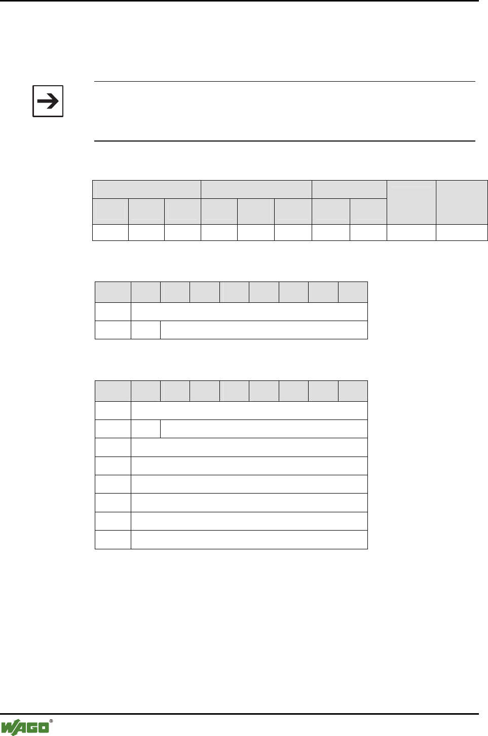
188 • Appendix
Mailbox Command References
WAGO-I/O-SYSTEM 750
I/O Modules
6.3.6.9 Read the Operating Time of the Module (GetLocalUpTime, 0xDB)
With call up, the operating time of the module since the last reboot can be
read.
Note
This function serves as an aid for the error search; for example, to test power
failures. The accuracy of the time measurement is not designed to enable pre-
cise time measurement over longer periods of time.
Conditions
Mailbox size Operating mode/profile Device role
6 12 18 Config. Real-
time Ad hoc Master Slave
Save
config. Restart
(●) ● ● ● ● ● ● ● - -
Request
Byte 27 26 25 24 23 22 21 20
0 MBX_UPTIME
1 T -
Response
Byte 27 26 25 24 23 22 21 20
0 MBX_UPTIME
1 T MBX_RESULT
2 MBX_MINUTES
3 MBX_HOURS
4 MBX_DAYS (LSB)
5 MBX_DAYS
6 (optional) MBX_DAYS
7 (optional) MBX_DAYS (MSB)

Appendix • 189
Mailbox Command References
WAGO-I/O-SYSTEM 750
I/O Modules
Return values
Parameter Value Description
MBX_MINUTES [0...59] Minute portion of the operating
time
MBX_HOURS [0...24] Hour portion of the operating time
MBX_DAYS Mailbox size 6: [0…65.535]
Mailbox size > 6: [0…4.294.967.295]
Number of days the module has
been operating;
The two higher value bytes are
only available with a mailbox > 6

190 • Appendix
Extended Register Structure (Configuration Block)
WAGO-I/O-SYSTEM 750
I/O Modules
6.4 Extended Register Structure (Configuration Block)
Offset
(byte)
Register
no.
Length
(bytes) Data Type Definition Description
9
Device status:
Byte 1 local status
Byte 2 status of master, slave 0
Byte 3 status of slave 1,2
Byte 4 status of slave 3,4
Byte 5 status of slave 5,6
Byte 6 status of external device 0,1
Byte 7 status of external device 2,3
Byte 8 status of external device 4,5
Byte 9 status of external device 6,7
Local status
Is 0 if all configured, but at least one
WAGO device are connected. Oth-
erwise always 1.
Status of master, slaves or external
devices, 4 bits per device:
0 – not connected
1 – connection established
2 – connection exists
3 – device has been "parked".
1 Version of main configuration
0 0…2
2 Version of the subconfiguration
Version of the configuration (see
Appendix 6.3.3.3)
12 3 4 Configuration key Identification of the configuration
must have the value 0x1E55F15E
1 Process image size Size of the module bus process im-
age in bytes.
1 Size and type of the mailbox inter-
face
Bit 0…14: Size of the mailbox. Bit
15: Must have the value "1" (mail-
box type can be "faded in")
1 Reserved
16 4
1 Technology 1 – Bluetooth®
6 Local MAC address Local address of the Bluetooth®
module, LSB first (see Appendix
6.3.5.3)
1 Profiles supported Bit field for the supported profiles;
the individual values are linked
binarily using OR:
1 – Lesswire L2CAP
2 – SPP
4 – PAN
1 Local device role See Appendix 6.3.5.20 and 6.3.5.21
1 ID of the communication profile See Appendix 6.3.5.10 and 6.3.5.11
20 5…7
3 Reserved
1 WAGO device class See Appendix 6.3.5.8 and 6.3.5.9
1 WAGO device subclass See Appendix 6.3.5.8 and 6.3.5.9
1 Encryption mode See Appendix 6.3.5.12 and 6.3.5.13
32 8
1 Use "Link Key" 0 – no authentication or PIN
1 – Authentication with "Link Key"
- see Appendix 6.3.5.14 and 6.3.5.15

Appendix • 191
Extended Register Structure (Configuration Block)
WAGO-I/O-SYSTEM 750
I/O Modules
Offset
(byte)
Register
no.
Length
(bytes) Data Type Definition Description
36 9…12 16 Local device name See Appendix 6.3.5.1 and 6.3.5.2
52 13…14 8 Reserved
60 15…18 16 Password See Appendix 6.3.5.16 and 6.3.5.17
1
Inquiry time Maximum duration of a query
The exact time results from: Inquiry
Time * 1.28sec
1 Reserved
76 19
2 Reconnection time Time between two attempts to con-
nection, LSB first (see Appendix
6.3.5.33 and 6.3.5.34)
4 IP Address Local IP address, LSB first (see
Appendix 6.3.5.4 and 6.3.5.5)
4 Subnet Mask Local subnet mask, LSB first (see
Appendix 6.3.5.6 and 6.3.5.7)
80 20…22
4 IP address of the gateway IP address of the gateway, LSB first
92 22…23 8 Reserved
Slave configuration for 13 devices,
28 bytes per device:
Configuration for 13 remote devices:
Bytes 1…6: MAC address Local address of the Bluetooth®
module, LSB first
(see Appendix 6.3.5.24)
Byte 7: Bind/Unbind 1 – device has been linked
0 – other
(see Appendix 6.3.5.28 and
6.3.5.29)
Byte 8: Max. Process data
length
Configured width of the slot in the
process image size of the available
process data
Byte 9: Process image size of
the remote device
Process image size of the remote
device (see Appendix 6.3.4.1)
Bytes 10, 11: Reserved
Byte 12: supported profiles Received value for the bit field of
the supported profiles. The individ-
ual values are linked binarily using
OR:
1 – Lesswire L2CAP
2 – SPP
4 – PAN
100 24...114
(13*7
register)
364
(13*28
bytes)
Bytes 13…28: UserFriendlyName User-friendly name
(see Appendix 6.3.5.35)
464 115…
128
48 Reserved

192 • Appendix
Extended Register Structure (Configuration Block)
WAGO-I/O-SYSTEM 750
I/O Modules
Fields identified as reserved are set to 0 and ignored by the module. The ex-
tended register structure of each module is saved for the run time in a 512-byte
block of 128 registers of 4 bytes each.
For all opcodes, for which "Save Config." is marked in the requirements, all
current settings are written in the non-volatile flash memory.
The structure of the data in the flash memory is differentiated from the ex-
tended register structure. The extended register structure only exists in the
RAM and is created for the run time.
The extended register structure is read using DLD commands in the configura-
tion mode or by querying individual values through opcodes. It behaves in a
manner similar to that for writing the configuration.
Appendix • 193
Example Configurations using WAGO-I/O-CHECK
WAGO-I/O-SYSTEM 750
I/O Modules
6.5 Example Configurations using WAGO-I/O-CHECK
6.5.1 Startup with the Bluetooth® Parameterization Dialog
This Section can be used for the startup and configuration of Bluetooth® mod-
ules using the WAGO-I/O-CHECK software.
The following startup example demonstrates how to start the module up with
minimal configuration, and therefore does not describe the entire range of
functions. The objective of these instructions is to configure a simple peer-to-
peer communication between two Bluetooth® modules. One module will func-
tion as a master, the other as a slave.
6.5.1.1 Network Structure
1. Construct two identical bus nodes as shown in Figure 44.
• 750-841 Ethernet Controller
• 750-644 Bluetooth® RF Transceiver
• 750-600 End Module
2. Connect one of the controllers to a free serial port of your PC using a
WAGO communication cable (750-920).
3. Connect the second controller in the same manner to another serial port of
your PC.
Attention
Do not form a fieldbus connection (e.g., by using an ETHERNET cable);
otherwise, access to the process data within WAGO-I/O-CHECK is not pos-
sible.
4. Connect both nodes on the system and field sides with a 24-volt power
supply.
5. Switch the power supply on.
Additional Information
Each serial PC port is operated by its own WAGO-I/O-CHECK software.
Depending on port availability, use one or two PCs for configuring the mod-
ules.
If you are using one PC with two ports, the WAGO-I/O-CHECK software
can be started several times. You can select the proper COM ports using the
"F8" key on your keyboard. If using only one port or one WAGO-I/O-
CHECK, the configuration of master and slaves is rather time-consuming.
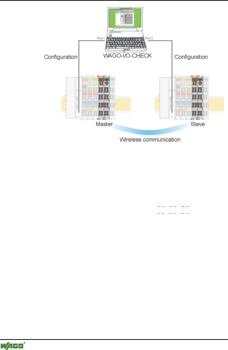
194 • Appendix
Example Configurations using WAGO-I/O-CHECK
WAGO-I/O-SYSTEM 750
I/O Modules
Figure 44: Hardware configuration g064461e
6.5.1.2 Starting up the Bluetooth® Modules
1. Determine which of your Bluetooth® modules will function as the master
and which module will function as the slave.
2. Write down the MAC address of the slave: 0 0 : 0 6 : C 6 : _ _ : _ _ : _ _
Write down the MAC address of the master: 0 0 : 0 6 : C 6 : _ _ : _ _ : _ _
6.5.1.2.1 Configuration of the Bluetooth® Slave using "Net Forming"
1. Start the WAGO-I/O-CHECK software (Version 3 or later).
2. Click on the [Identify] button.
Your node configuration is graphically displayed (see Figure 45).
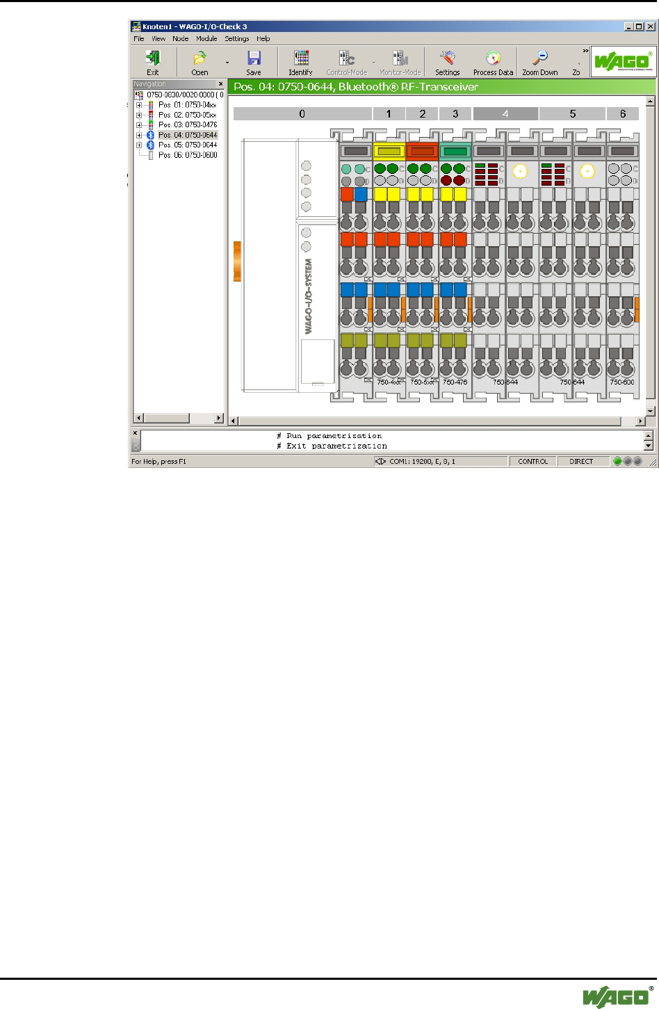
Appendix • 195
Example Configurations using WAGO-I/O-CHECK
WAGO-I/O-SYSTEM 750
I/O Modules
Figure 45: Identify your node configuration g064462e
3. Click with the right mouse button on the Bluetooth® module that you
would like to configure as a slave.
4. In the module's context menu, choose Settings. This opens the Bluetooth®-
specific parameterization dialog of the module (see Figure 46).
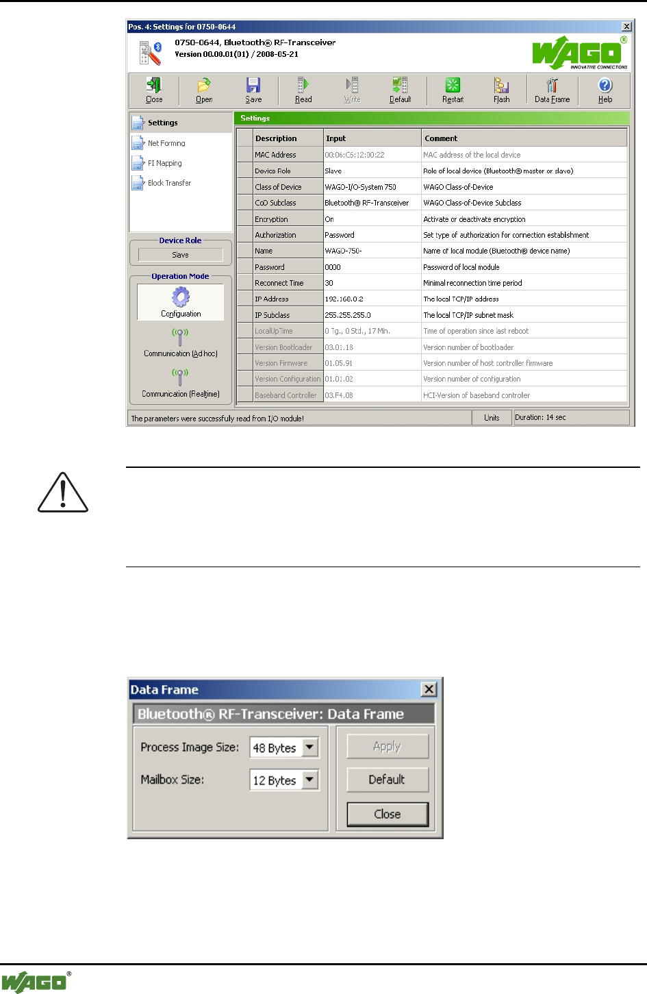
196 • Appendix
Example Configurations using WAGO-I/O-CHECK
WAGO-I/O-SYSTEM 750
I/O Modules
Figure 46: Bluetooth®-specific parameter area g064418e
Attention
In order to perform the following steps, the Bluetooth®module must retain all
factory settings (default settings); i.e, you have not yet attempted any con-
figuration. If this is not the case, click on the [Default] button to reset the
module's configuration.
5. Click on [Data Frame] in the toolbar.
6. Enter (if not already set) a process image size of 48 bytes and a mailbox
size of 12 bytes (see Figure 47).
Figure 47: Data structure g064444e
7. Click on the [Read] button in the toolbar to update the view of the con-
figuration in the module.
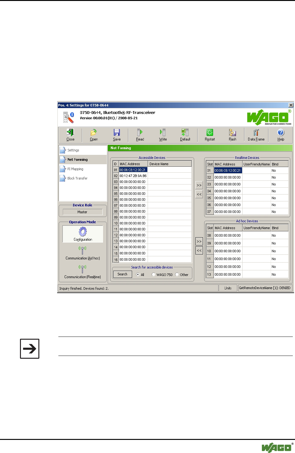
Appendix • 197
Example Configurations using WAGO-I/O-CHECK
WAGO-I/O-SYSTEM 750
I/O Modules
8. Choose Net Forming in the navigation bar.
9. Choose the option All in the area Search for accessible devices and click
on the [Search] button to search the network for Bluetooth® devices in the
environment. To limit the search results to WAGO 750 Series devices,
choose WAGO 750 instead.
The MAC addresses of all located Bluetooth® devices are displayed in the list
of devices within range (see Figure 48).
The MAC address of the slave itself is displayed in this dialog.
Figure 48: Net forming g064463e
10. Search in the list for the MAC Address of the master that you wrote down
in 6.5.1.2 so you can connect this master to your slave.
Note
At this point, the master must be in the configuration mode (factory setting).
11. Mark the found MAC Address of the master with a mouse click.
12. Click on the [>>] button to transfer the marked MAC Address to the list of
real-time devices (or ad hoc devices) for this slave.
The MAC Address of the master is entered in the first line (slot 1).
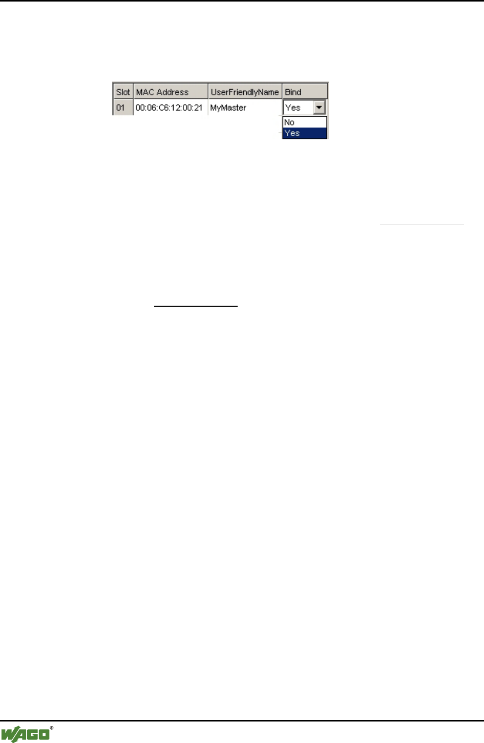
198 • Appendix
Example Configurations using WAGO-I/O-CHECK
WAGO-I/O-SYSTEM 750
I/O Modules
13. Give the device a name (UserFriendlyName), e.g. "MyMaster".
14. Mark the MAC Address and choose the value "Yes" in the dropdown field
Bind (see Figure 49).
Figure 49: Bind device g064464e
15. Click on the [Write] button in the toolbar to write the altered configura-
tion in the module.
You have now allocated a master to the Bluetooth® slave (Slave ! Master).
16. Under navigation in the Operating Mode field, choose the real-time mode
using the [Communication (Realtime)] button.
17. Proceed as in Section 6.5.1.2.2 to create a link from the side of the master
as well (Master ! Slave).
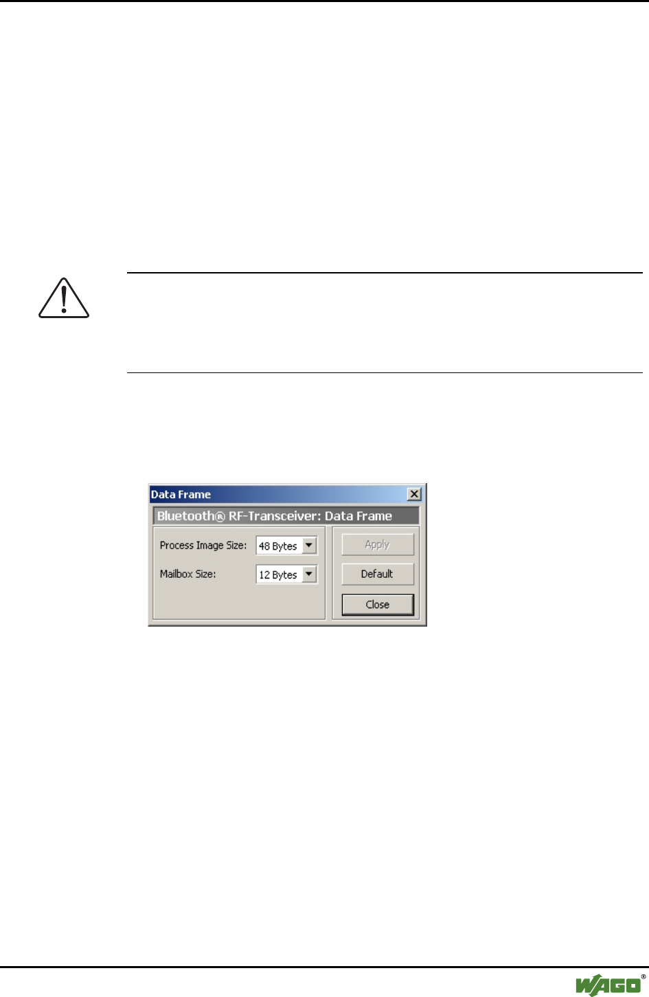
Appendix • 199
Example Configurations using WAGO-I/O-CHECK
WAGO-I/O-SYSTEM 750
I/O Modules
6.5.1.2.2 Configuration of the Bluetooth® Master using "Net Forming"
1. Start WAGO-I/O-CHECK software (Version 3 or later).
2. Click on the [Identify] button.
Your node configuration is graphically displayed.
3. Click with the right mouse button on the Bluetooth® module that you
would like to configure as a slave.
4. Choose Settings in the context menu. This opens a new window for the
configuration of the module.
Attention
In order to perform the following steps, the Bluetooth module must retain all
factory settings (default settings); i.e, you have not yet attempted any con-
figuration. If this is not the case, click on the [Default], button to reset the
module's configuration.
5. Click on [Data Frame] in the toolbar.
6. Enter (if not already set) a process image size of 48 bytes and a mailbox
size of 12 bytes (see Figure 50).
Figure 50: Data Frame g064444e
7. Click on the [Read] button in the toolbar to update the view of the con-
figuration in the module.
8. In the list on the right side, assign the role of master to the module by
choosing "Master" under Device Role.
9. Choose the menu item Net Forming in the navigation bar.
The following section describes how to select the devices required to establish
a connection to the master. Devices that are visible for search requests can
first be searched for in a similar way to slave’s configuration (see Section
6.5.1.2.1, steps 9-12). They may also then be stored using "Drag & Drop" —
an example being dropping and dragging from the search results into the list
of authorized devices (slots 1…13). However, for safety reasons, WAGO de-

200 • Appendix
Example Configurations using WAGO-I/O-CHECK
WAGO-I/O-SYSTEM 750
I/O Modules
vices are hidden for search request in communication operating mode; they
may also be entered like other hidden devices or devices being out of reach:
10. Enter the listed MAC address of the slave, which is already set in the
communication operating mode, manually in the allocated field. The fol-
lowing steps assume that you are using slot 1.
11. Give the device a name (UserFriendlyName), e.g., "Slave_01". This makes
the overview easier for you.
12. Mark the slot with the entered MAC address and choose the value "Yes" in
the dropdown field Bind.
13. Click on the [Write] button in the toolbar to write the altered configura-
tion in the module.
Master and slave are now assigned to each other. The master is still in con-
figuration mode.
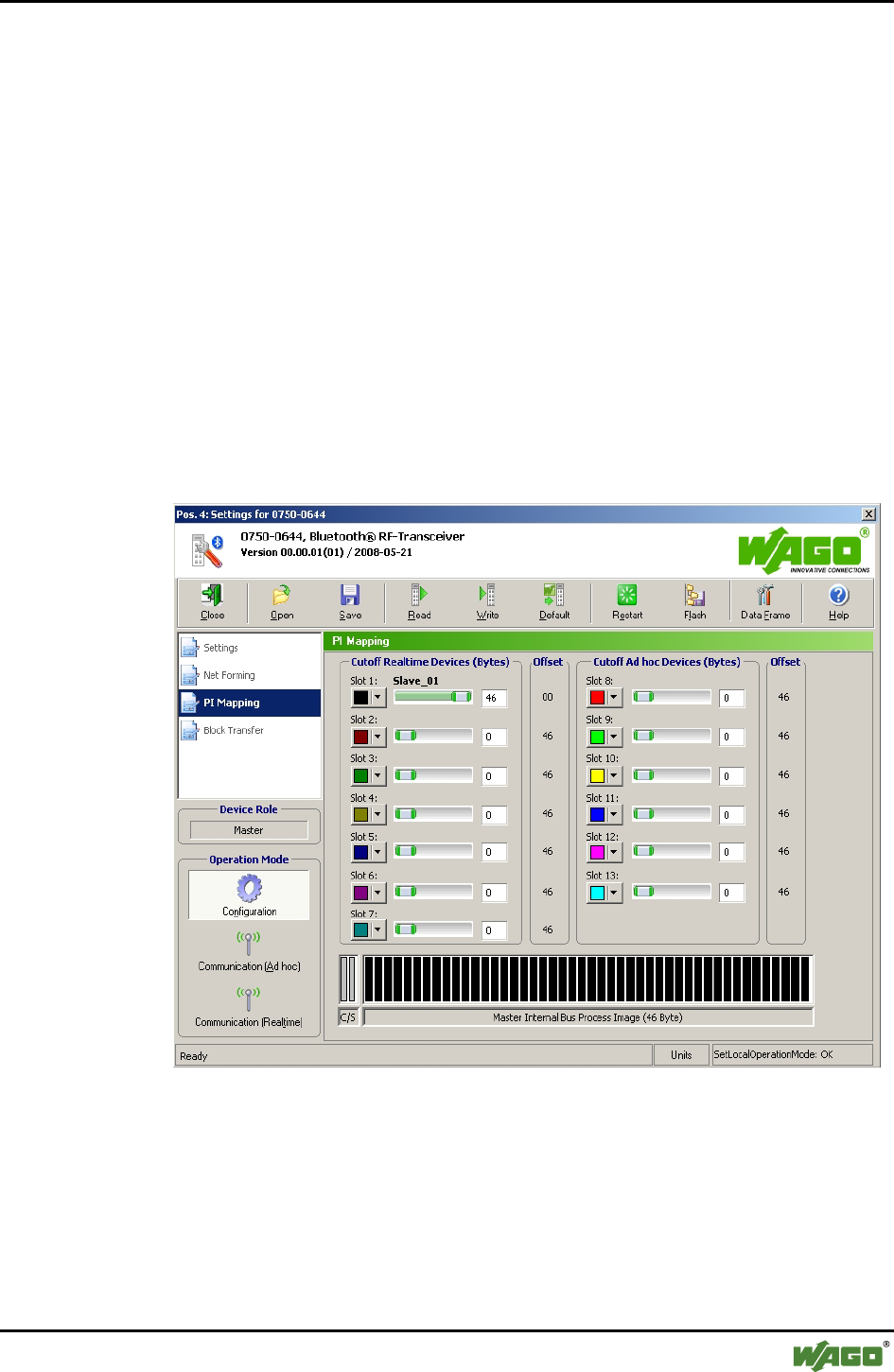
Appendix • 201
Example Configurations using WAGO-I/O-CHECK
WAGO-I/O-SYSTEM 750
I/O Modules
6.5.1.2.3 Process Data Allocation
Start with point 3 while the Bluetooth® parameterization dialog (siehe Figure
51) is still open.
1. Click with the right mouse button on the Bluetooth® module (master)
2. Choose Settings in the context menu. This opens a new window for mod-
ule configuration.
3. In the navigation, choose the menu item PI-Mapping.
The process data allocation is loaded from the module and graphically dis-
played in WAGO-I/O-CHECK.
4. Move the ruler for the first slave to the right so that the first slave is as-
signed the maximum possible number of bytes in the process image of the
master (see Figure 51).
Figure 51: PI Mapping g064465e
5. Click on the [Write] button in the toolbar to write the altered configura-
tion in the module.
6. Under navigation in the Operating Mode field, choose the real-time field
using the [Communication (Realtime)] button.
The example configuration is completed.
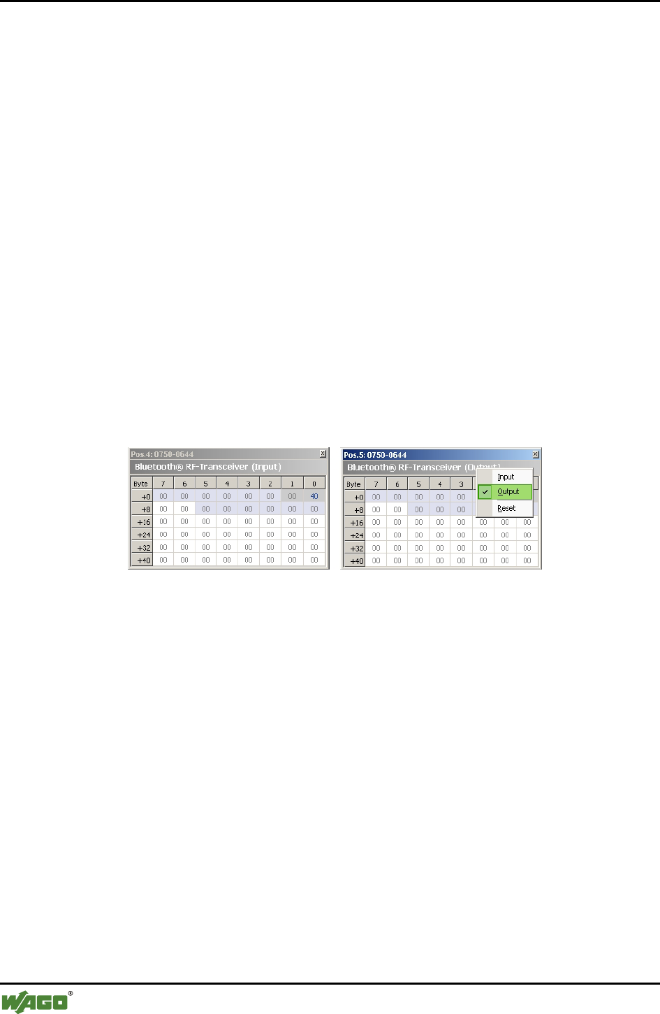
202 • Appendix
Example Configurations using WAGO-I/O-CHECK
WAGO-I/O-SYSTEM 750
I/O Modules
6.5.1.3 Testing the Process Data Exchange
The prerequisite for a successful test of the process data exchange is the cor-
rect configuration of the Bluetooth® device (see Appendix 6.5.1.2.1 through
6.5.1.2.3). The connection between the Bluetooth® master and slave is indi-
cated by the constant green blinking of LED 2 (see Figure 3) of the Blue-
tooth® master.
1. Close the Bluetooth® parameterization dialog.
2. Right click on master and slave, one after the other.
3. Choose Process Data in the context menu.
The process data dialog opens so that you can view the raw data.
4. Click with the right mouse button on the word "Input" in the dialog of the
master.
You have the choices Input, Output and Reset. From now on, you can switch
between the displays for input and output data using this menu (see Figure
52).
Figure 52: View of the process data g064466e
5. Enter any data in the "Output" dialog:
• in the process image of the master and slave beginning with offset + 2
(bytes 0 and 1 are reserved for status information)
6. Test whether the input data of the first Bluetooth® module leads to the
correct output data of the second Bluetooth® module.
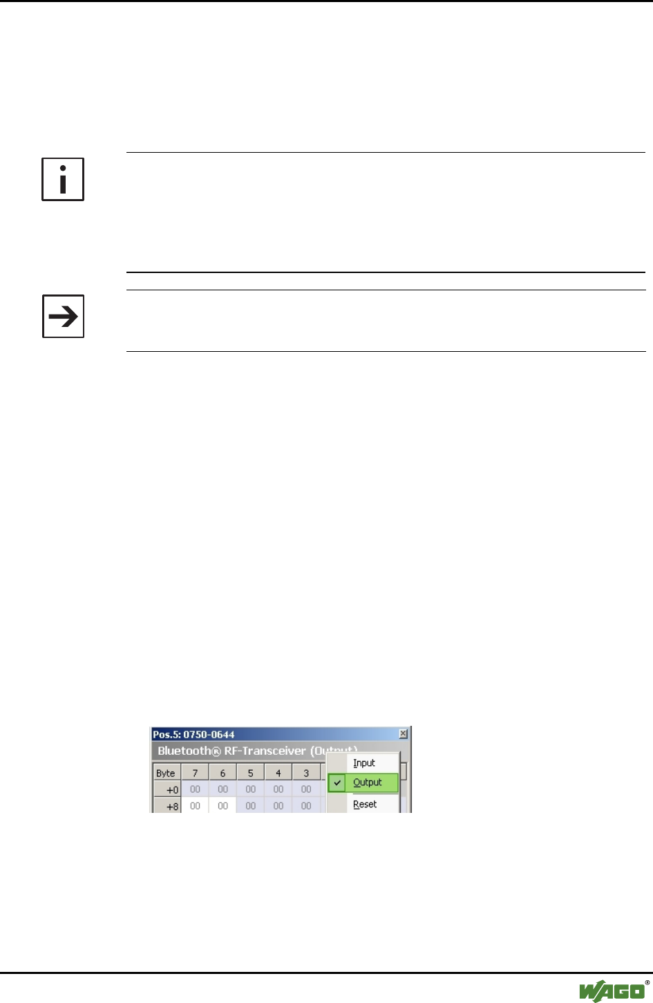
Appendix • 203
Example Configurations using WAGO-I/O-CHECK
WAGO-I/O-SYSTEM 750
I/O Modules
6.5.2 Startup using Mailbox Commands in the Process Data Dialog
In addition to configuring modules in the Bluetooth® parameterization dialog,
it is also possible to configure using mailbox commands. Mailbox commands
are entered via function blocks in WAGO-I/O-PRO CAA or in the process
data dialog of WAGO-I/O-CHECK. Here, WAGO-I/O-CHECK is used.
Additional Information
The configuration program WAGO-I/O-CHECK is a helpful tool you can use
to enter/execute mailbox commands as hexadecimal opcodes and view the
result in the input data.
You can obtain the software on a CD ROM with order number 759-302 from
WAGO Kontakttechnik GmbH & Co. KG.
Note
Mailbox commands are executed when a new opcode is entered and/or when
the toggle bit is changed.
6.5.2.1 Network Structure
In the following example, a Bluetooth® master is configured with four Blue-
tooth® slaves. To do this, you should have five Bluetooth® devices in your
network.
6.5.2.2 Starting up the Bluetooth® Modules
1. Click on [Identify] in WAGO-I/O-CHECK to graphically display your
node.
2. Click with the right mouse button on a Bluetooth® module and choose
Process Data.
3. In the new window, click with the right mouse button on the header "Blue-
tooth® RF Transceiver".
4. In the context menu, choose Output Data (see Figure 53).
Figure 53: Display Bluetooth® output data g064467e
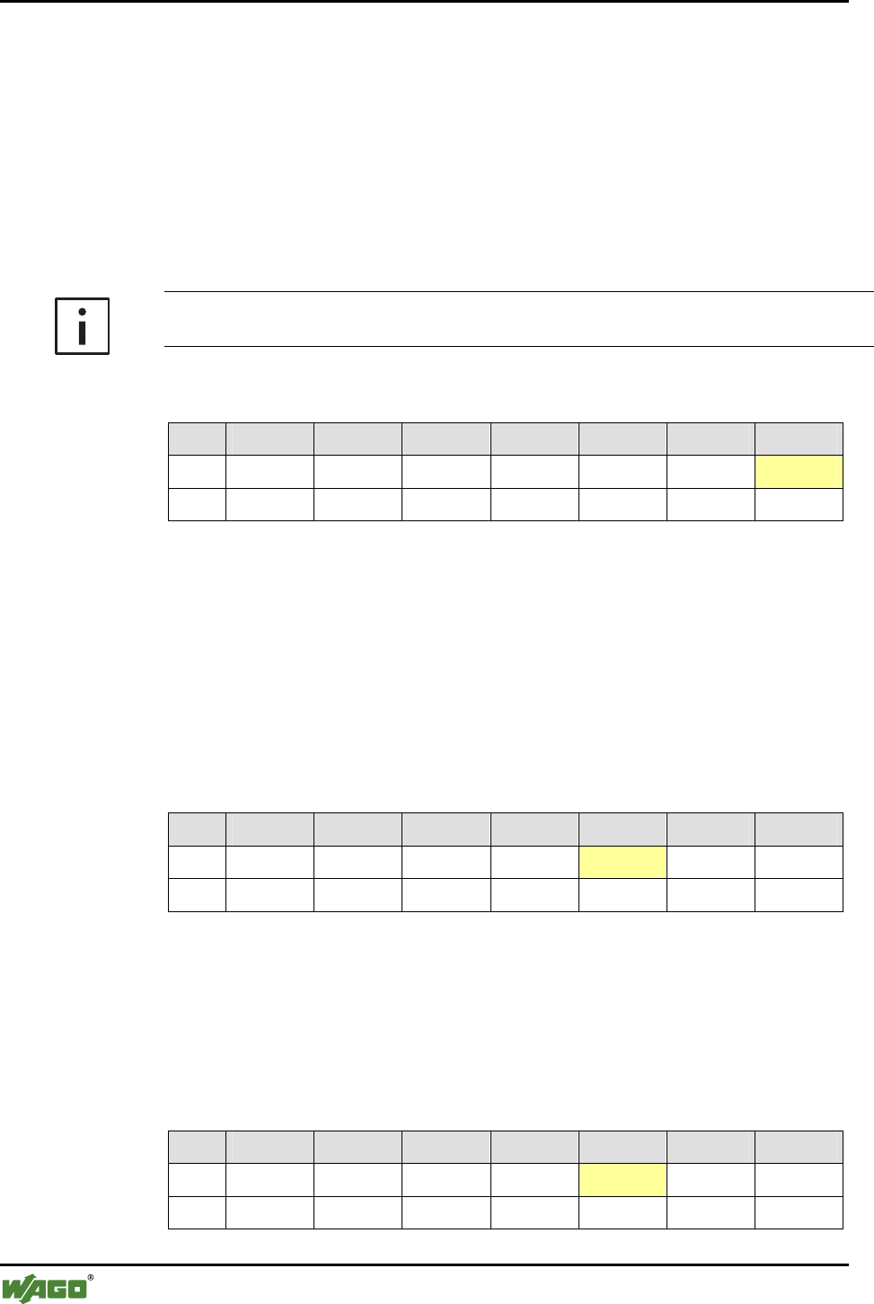
204 • Appendix
Example Configurations using WAGO-I/O-CHECK
WAGO-I/O-SYSTEM 750
I/O Modules
6.5.2.2.1 Switch the Mailbox on
1. Switch the mailbox of all modules on by setting the control byte to 0x20
(bit 25=1) (see Table 36).
Different error/warning bits can be set in the status byte depending on the de-
livery condition. The switched on mailbox is confirmed in byte 0 (status byte)
with 0x60: 60hex = 0110.0000bin ! bit 25 and 26 are set
Bit 25 will confirm the switched on mailbox while bit 26 will display a still in-
active wireless connection.
Additional Information
The description of the control and status bit can be found in Section 2.1.1.8.1.1.
Table 36: Switching the mailbox on
Byte 6 5 4 Toggle Opcode empty C/S
PD/O 0x00 0x00 0x00 0x00 0x00 0x00 0x20
PD/I 0x00 0x00 0x00 0x00 0x00 0x00 0x60
6.5.2.2.2 Reset Modules to Factory Default
1. Reset all modules to the factory settings using the mailbox command "Set-
FactorySettings" (opcode 0x57) (see Table 37).
2. Wait five seconds after the execution of the command before continuing so
that the internal Bluetooth® subsystem can change over.
Table 37: Mailbox command "SetFactorySettings"
Byte 6 5 4 Toggle Opcode empty C/S
PD/O 0x00 0x00 0x00 0x00 0x57 0x00 0x20
PD/I 0x00 0x00 0x00 0x00 0x57 0x00 0x60
3. Execute the command "FlashRebootHost" (opcode 0x11) for all modules
(see Table 37) to restart them.
4. Wait five seconds after the execution.
Table 38: Mailbox command "FlashRebootHost"
Byte 6 5 4 Toggle Opcode empty C/S
PD/O 0x00 0x00 0x00 0x00 0x11 0x00 0x20
PD/I 0x00 0x00 0x00 0x00 0x11 0x00 0x60
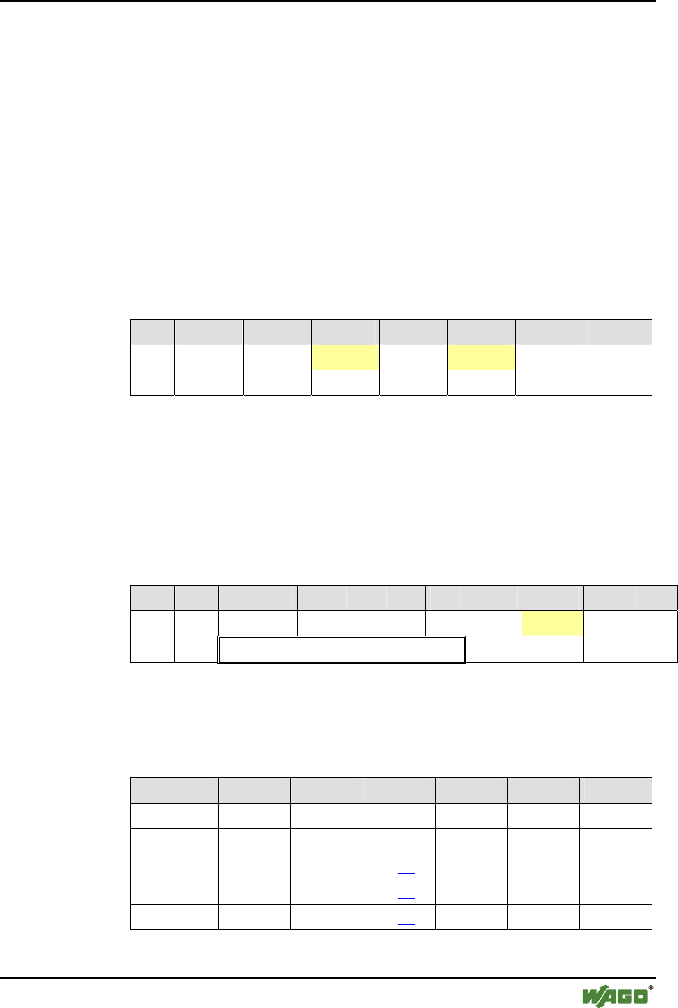
Appendix • 205
Example Configurations using WAGO-I/O-CHECK
WAGO-I/O-SYSTEM 750
I/O Modules
6.5.2.2.3 Determining the Master
1. Choose one of the modules to be the master and set byte 4 to 0x01
(MBX_DEVICE_ROLE).
2. Execute the mailbox command "SetLocalDeviceRole" (opcode 0x56) for
this module to assign it the role of master.
3. Wait five seconds after the execution so that the internal Bluetooth® sub-
system can change over.
The remaining four Bluetooth® modules are already configured as slaves by
the factory setting.
Table 39: Mailbox command "SetLocalDeviceRole"
Byte 6 5 4 Toggle Opcode empty C/S
PD/O 0x00 0x00 0x01 0x00 0x56 0x00 0x20
PD/I 0x00 0x00 0x00 0x00 0x56 0x00 0x60
6.5.2.2.4 Querying the MAC Address
1. To query the MAC addresses of the master and slaves, use the mailbox
command "GetLocalMacID" (opcode 0x42) (see Table 40). Execute the
command for all modules.
Table 40: Mailbox command "GetLocalMacID"
Byte 10 9 8 7 6 5 4 Toggle Opcode empty C/S
PD/O 0x00 0x00 0x00 0x00 0x00 0x00 0x00 0x00 0x42 0x00 0x20
PD/I 0x00 0x00 0x06 0xC6 0x__ 0x__ 0x__ 0x00 0x42 0x00 0x60
2. Take note of the return values of bytes 4 through 9 in Table 40 below:
Table 41: Entering return values
Byte 9 8 7 6 5 4
Master 0x00 0x06 0xC6 0x___ 0x___ 0x___
Slave 1 0x00 0x06 0xC6 0x___ 0x___ 0x___
Slave 2 0x00 0x06 0xC6 0x___ 0x___ 0x___
Slave 3 0x00 0x06 0xC6 0x___ 0x___ 0x___
Slave 4 0x00 0x06 0xC6 0x___ 0x___ 0x___

206 • Appendix
Example Configurations using WAGO-I/O-CHECK
WAGO-I/O-SYSTEM 750
I/O Modules
Moving forward, the return values (MAC addresses) of the master will be re-
vealed to the slaves and the return values of the slaves will be revealed to the
master.
6.5.2.2.5 Loading the MAC Addresses of the Slaves into the Device List of the
Master
1. In bytes 5 through 10 of the master, write the MAC address of the first
Bluetooth® slave (see Table 42).
2. Using 0x20 (TABLE_ENTRY) in byte 4, indicate the first table entry in
which the MAC address is to be written.
3. Use the mailbox command "AllowRemoteDevice" (opcode 0x83) to load
the MAC address of this slave in the device list of the master.
Table 42: Mailbox command "AllowRemoteDevice"
Byte 10 9 8 7 6 5 4 Toggle Opcode empty C/S
PD/O 0x00 0x06 0xC6 0x__ 0x__ 0x__ 0x20 0x00 0x83 0x00 0x20
PD/I 0x00 0x00 0x00 0x00 0x00 0x00 0x00 0x00 0x83 0x00 0x60
4. In bytes 5 through 10 of the master, write the MAC address of the first
Bluetooth® slave (see Table 42).
5. Using 0x21 (TABLE_ENTRY) in byte 4, indicate the second table entry in
which the MAC address is to be written.
6. Since opcode 0x83 has not changed, but the mailbox command is to be
executed again with the MAC address entered under 4, change the toggle
bit to 0x80.
Table 43: Mailbox command "AllowRemoteDevice"
Byte 10 9 8 7 6 5 4 Toggle Opcode empty C/S
PD/O 0x00 0x06 0xC6 0x__ 0x__ 0x__ 0x21 0x80 0x83 0x00 0x20
PD/I 0x00 0x00 0x00 0x00 0x00 0x00 0x00 0x80 0x83 0x00 0x60
7. In bytes 5 through 10 of the master, write the MAC address of the third
Bluetooth® slave (see Table 44).
8. Using 0x22 (TABLE_ENTRY) in byte 4, indicate the third table entry in
which the MAC address is to be written.
9. Change the toggle byte to 0x00 to execute the mailbox command (opcode
0x83) again.
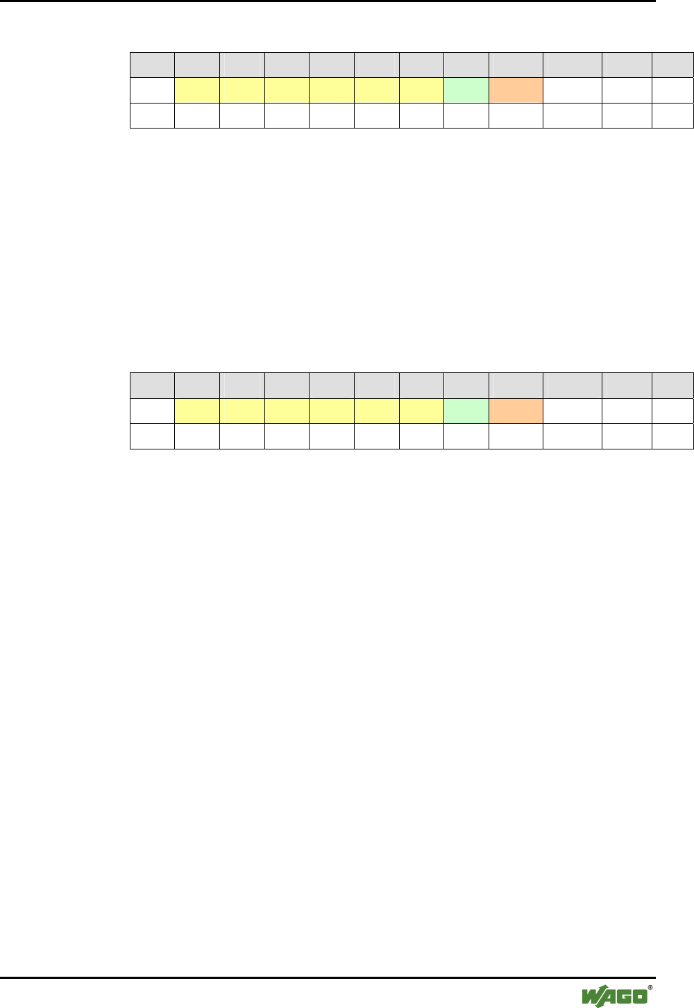
Appendix • 207
Example Configurations using WAGO-I/O-CHECK
WAGO-I/O-SYSTEM 750
I/O Modules
Table 44: Mailbox command "AllowRemoteDevice"
Byte 10 9 8 7 6 5 4 Toggle Opcode empty C/S
PD/O 0x00 0x06 0xC6 0x__ 0x__ 0x__ 0x22 0x00 0x83 0x00 0x20
PD/I 0x00 0x00 0x00 0x00 0x00 0x00 0x00 0x00 0x83 0x00 0x60
10. In bytes 5 through 10 of the master, write the MAC address of the fourth
Bluetooth® slave (see Table 45).
11. Using 0x23 (TABLE_ENTRY) in byte 4, indicate the fourth table entry in
which the MAC address is to be written.
12. Change the toggle byte to 0x80 to execute the mailbox command (opcode
0x83) again.
Table 45: Mailbox command "AllowRemoteDevice"
Byte 10 9 8 7 6 5 4 Toggle Opcode empty C/S
PD/O 0x00 0x06 0xC6 0x__ 0x__ 0x__ 0x23 0x80 0x83 0x00 0x20
PD/I 0x00 0x00 0x00 0x00 0x00 0x00 0x00 0x80 0x83 0x00 0x60

208 • Appendix
Example Configurations using WAGO-I/O-CHECK
WAGO-I/O-SYSTEM 750
I/O Modules
6.5.2.2.6 Loading the MAC Address of the Master into the Device Lists of the
Slaves
1. Enter the MAC address of the master in bytes 5 through 10 of the first
slave.
2. For each slave, set byte 4 to 0x20 (TABLE_ENTRY).
3. Use the mailbox command "AllowRemoteDevice" (opcode 0x83) to load
the master in the device list of the slave (see Table 46).
4. Proceed in the same manner with the remaining slaves.
Table 46: Mailbox command "AllowRemoteDevice"
Byte 10 9 8 7 6 5 4 Toggle Opcode empty C/S
PD/O 0x00 0x06 0xC6 0x__ 0x__ 0x__ 0x20 0x80 0x83 0x00 0x20
PD/I 0x00 0x00 0x00 0x00 0x00 0x00 0x00 0x80 0x83 0x00 0x60
6.5.2.2.7 Binding the Slaves in the Master
1. Write the MAC address of the first Bluetooth® slave in bytes 5 through 10
of the master (see Table 47).
2. Set byte 4 to 0x20 (TABLE_ENTRY).
3. Use the mailbox command "BindRemoteDevice" (opcode 0x85) to load the
MAC address of this slave in the device list of the master.
Table 47: Mailbox command "BindRemoteDevice" for binding Slave 1
Byte 10 9 8 7 6 5 4 Toggle Opcode empty C/S
PD/O 0x00 0x06 0xC6 0x___ 0x___ 0x___ 0x20 0x00 0x85 0x00 0x20
PD/I 0x00 0x06 0xC6 0x___ 0x___ 0x___ 0x00 0x00 0x85 0x00 0x60
4. Write the MAC address of the second Bluetooth® slave in bytes 5 through
10 of the master (see Table 47).
5. Set byte 4 to 0x21 (TABLE_ENTRY).
6. Change the toggle byte to 0x80 to execute the mailbox command (opcode
0x85) again.
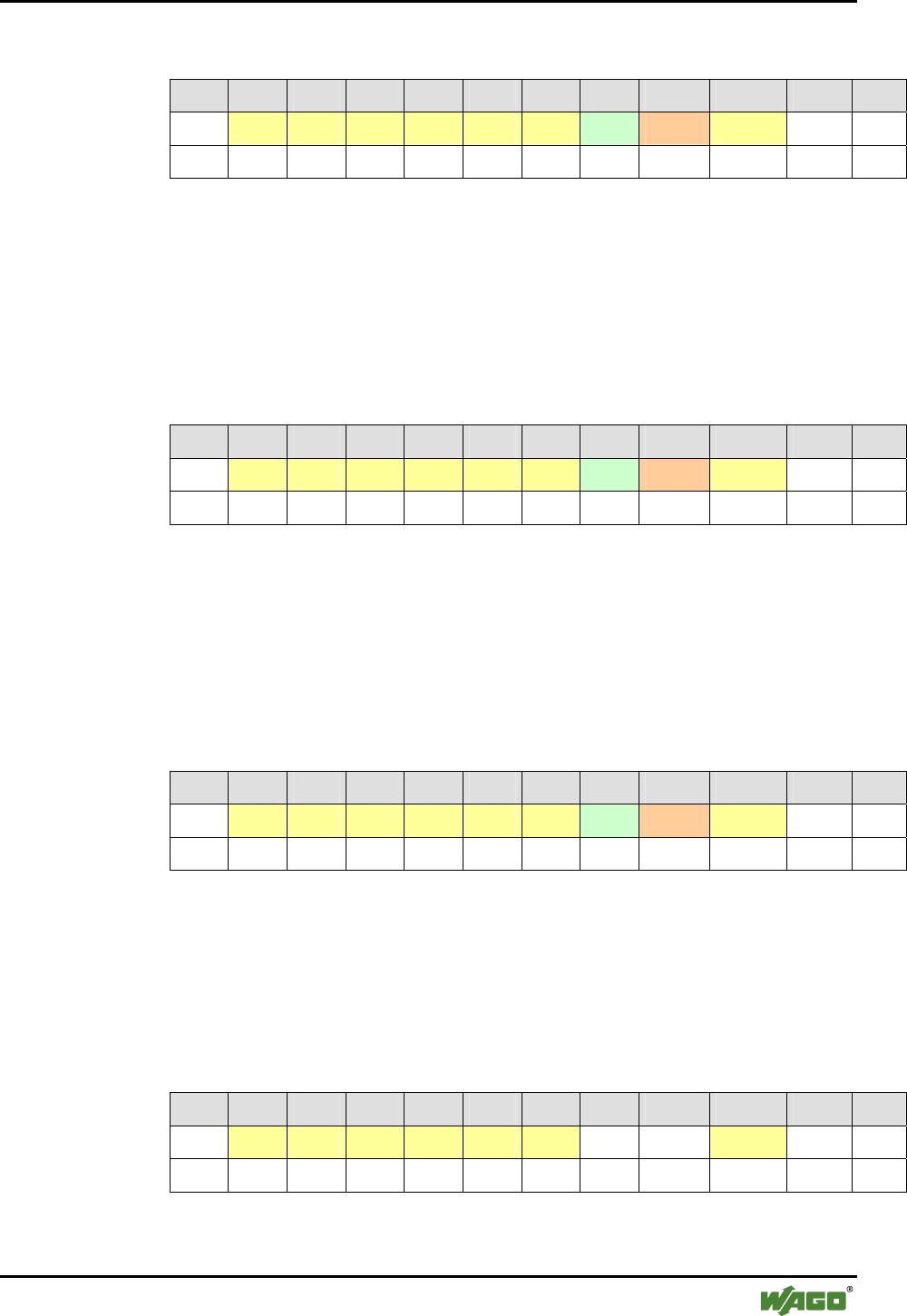
Appendix • 209
Example Configurations using WAGO-I/O-CHECK
WAGO-I/O-SYSTEM 750
I/O Modules
Table 48: Mailbox command "BindRemoteDevice" for binding Slave 2
Byte 10 9 8 7 6 5 4 Toggle Opcode empty C/S
PD/O 0x00 0x06 0xC6 0x___ 0x___ 0x___ 0x21 0x80 0x85 0x00 0x20
PD/I 0x00 0x06 0xC6 0x___ 0x___ 0x___ 0x00 0x80 0x85 0x00 0x60
7. Write the MAC address of the third Bluetooth® slave in bytes 5 through 10
of the master (see Table 49).
8. Change the toggle byte to 0x00 to execute the mailbox command (opcode
0x85) again.
Table 49: Mailbox command "BindRemoteDevice" for binding Slave 3
Byte 10 9 8 7 6 5 4 Toggle Opcode empty C/S
PD/O 0x00 0x06 0xC6 0x___ 0x___ 0x___ 0x22 0x00 0x85 0x00 0x20
PD/I 0x00 0x06 0xC6 0x___ 0x___ 0x___ 0x00 0x00 0x85 0x00 0x60
9. Write the MAC address of the fourth Bluetooth® slave in bytes 5 through
10 of the master (see Table 50).
10. Change the toggle byte to 0x80 to execute the mailbox command (opcode
0x85) again.
Table 50: Mailbox command "BindRemoteDevice" for binding Slave 4
Byte 10 9 8 7 6 5 4 Toggle Opcode empty C/S
PD/O 0x00 0x06 0xC6 0x___ 0x___ 0x___ 0x23 0x80 0x85 0x00 0x20
PD/I 0x00 0x06 0xC6 0x___ 0x___ 0x___ 0x00 0x80 0x85 0x00 0x60
6.5.2.2.8 Binding the Master in the Slaves
1. Bind the master with the mailbox command "BindRemoteDevice" (opcode
0x85). Execute this command with each slave.
Table 51: Mailbox command "BindRemoteDevice" for binding the master
Byte 10 9 8 7 6 5 4 Toggle Opcode empty C/S
PD/O 0x00 0x06 0xC6 0x___ 0x___ 0x___ 0x20 0x80 0x85 0x00 0x20
PD/I 0x00 0x00 0x00 0x00 0x00 0x00 0x00 0x80 0x85 0x00 0x60

210 • Appendix
Example Configurations using WAGO-I/O-CHECK
WAGO-I/O-SYSTEM 750
I/O Modules
6.5.2.2.9 Setting the Communication Mode for Master and Slaves
1. Set all Bluetooth® slaves with the mailbox command "SetLocalOperation-
Mode" (opcode 0x4A) to communication mode (0x03 for the ad hoc pro-
file) (see Table 52).
2. Follow the same steps for the Bluetooth® master.
3. Wait 5 seconds after the execution.
Table 52: Mailbox command "SetLocalOperationMode"
Byte 10 9 8 7 6 5 4 Toggle Opcode empty C/S
PD/O 0x00 0x00 0x00 0x00 0x00 0x03 0x02 0x80 0x4A 0x00 0x20
PD/I 0x00 0x00 0x00 0x00 0x00 0x00 0x00 0x80 0x4A 0x00 0x60
6.5.2.3 Testing the Process Data Exchange
Test the successful exchange of process data in the same manner as described
in Section 6.5.1.3.

Glossary • 211
WAGO-I/O-SYSTEM 750
I/O Modules
Glossary
A
Acyclic
Acyclic processes are triggered as needed and are used, for example, to react
to user input or special events.
Ad hoc profile
The ad hoc profile is one of two profiles in the communication mode sup-
ported by the Bluetooth® module. Special feature: In the ad hoc profile, the
module can also communicate with Bluetooth® devices from other manufac-
turers.
AFH
The adaptive frequency process "Adaptive Frequency Hopping" (AFH) is a
refinement of the FHSS and is used to temporarily "jump over" defective or
busy portions of the entire available frequency band and switch to other
channels.
See also "FHSS"
Application
An application is a specific use or function programmed by the user.
ASCII
ASCII (American Standard Code for Information Interchange) is a character
coding that includes 128 characters. Each character is described by 7 bits
(27=128). In addition to the Latin alphabet (upper and lower case letters),
Arabic numerals and some punctuation and control characters can be repre-
sented.
Authentication
Authentication is a process for testing the identity transmitted by a commu-
nication partner.
Authorized device
Devices with which connections may be established. No connection may be
established with devices that do not fall into this category.

212 • Glossary
WAGO-I/O-SYSTEM 750
I/O Modules
B
Baseband
A baseband is referred to if the desired signal is transmitted in an unaltered
frequency range. In wireless communication systems, wireless transmission
does not usually take place in the baseband, but rather by modulation of a
significantly higher frequency carrier signal with the baseband signal.
Binding
Bluetooth®-specific process in which a connection between two devices is
activated for data exchange.
Bit
A bit is the smallest information unit. Its value can either be 1 or 0.
Bit error rate
Generally: Frequency of bit errors in the data transmission.
Bluetooth® context: Information in percentage on recognized bit errors dur-
ing baseband transmissions. As a rule, packets recognized as defective can
be automatically repaired. If this is not possible, the defective data is auto-
matically discarded.
Bit rate
Number of bits transmitted within a specific time unit.
Blackout
Complete interruption of communication for a limited period of time.
Block
For this module: A block is a large area of data that belongs together in
which all configuration data is stored and can be accessed.
Block transfer
Configuration data of a block can be downloaded from the module or up-
loaded to the module using block transfer.

Glossary • 213
WAGO-I/O-SYSTEM 750
I/O Modules
Bootloader
The bootloader is software in the first block of the bootable system. It is
loaded and executed by the firmware and, in turn, starts other parts of the
operating system. The version status of the bootloader can be separately que-
ried.
Broadcast
In broadcast mode, this is a report transmitted to all stations connected to the
network.
Bus cycle
Single instance or advice of updating of cyclical process data within an SPS
bus node.
Byte (Binary Yoked Transfer Element)
A data element larger than a bit and smaller than a word. A byte generally
contains 8 bits. A byte may contain 9 bits in 36-bit computers.
C
Channel
See "Transmission channel"
Checksum
The formation of a test sum (checksum) is used to recognize errors in data
transmission or storage. There are different methods of forming a checksum.
Usually, redundant bits calculated from the report itself are attached to a re-
port. These bits are calculated again after data transmission and compared to
the checksum.
CoD
The Bluetooth® Class-of-Device (CoD) is a 24-bit field indicating to which
standard type of device (for example, mobile telephone or handsfree set)
Bluetooth® devices belong. In addition to standard types, manufacturer-
specific types can also be used.
The complete CoD for the WAGO Bluetooth® RF Transceiver 750-644 is
000000000010000011111000bin or 0x0020F8hex.

214 • Glossary
WAGO-I/O-SYSTEM 750
I/O Modules
Command
Instructions for the execution of certain actions.
Communication mode
Communication mode is an operation mode of the WAGO Bluetooth® mod-
ule in which cyclical data exchange with connected Bluetooth® devices oc-
curs.
Complex bus modules
Complex bus modules are a group of I/O modules that significantly exceed
the functional and application range of the input and output modules de-
scribed in the IEC-61131. Configuration/parameterization software is usu-
ally necessary for their use and/or there are special function blocks available.
The Bluetooth® module belongs to the group of complex bus modules.
Configuration mode
Operating mode of the WAGO Bluetooth® module in which the module can
be configured. In this mode, there is no data exchange with other Bluetooth®
devices. It can, however, conduct a wireless search for Bluetooth® devices
within range.
Confirmed service
Service for which the requestor receives a confirmation of the start and/or
execution from the executor.
Connection
Presence of at least one transmission channel between devices that commu-
nicate with each other.
Control byte
For this module: A specific byte of the cyclic process image output (PIO)
containing protocol information for acyclic services (register communica-
tion, parameter channels).
Coordinator
A device that also performs administrative tasks in addition to data transport
in a device network. An example of this is a Bluetooth® master that organ-
izes a piconet of up to seven slaves.

Glossary • 215
WAGO-I/O-SYSTEM 750
I/O Modules
Cutoff
Generally: limitation to a specific size of the portion of cyclical process data
allocated to a device.
Bluetooth® context: A Bluetooth® master only deals with excerpts of the
process images for connected Bluetooth® slaves. The size of these "excerpts"
is set by a "cutoff" in the configuration mode. The current data to be read
and written, which is assigned to slots in the master's process image, re-
mains.
Cycle time
The cycle time is the rate at which a cyclic process is repeated or the time
between two sequential starting points of a cyclic process, e.g. during the
updating of cyclic process data between module and coupler/controller or
between Bluetooth® devices connected wirelessly.
Cyclic
Cyclic processes are processes that recur at (regular) intervals.
D
Data exchange
Transmission of data between communication partners.
DC/DC
"Direct Current" (DC) is the English name for continuous current.
A direct current power controller (DC/DC transformer) is a self-controlled
converter that periodically switches to generate a different voltage at the out-
put. An area of application, for example, is electrical drive technology.
Device name
The Bluetooth® name of a device. This can be queried by other Bluetooth®
devices wirelessly.
Device role
Bluetooth® context: Difference between the function as coordinator (Blue-
tooth®-specific: master) or end device (Bluetooth®-specific: slave).

216 • Glossary
WAGO-I/O-SYSTEM 750
I/O Modules
Device within range
Devices are within physical range and are ready for connection or operation.
Diagnostics
Diagnostic information provides information on the system status, particu-
larly on disturbances or error conditions. Cyclic diagnostic information is
provided by the LED displays and the content of the status bytes. Acyclic
diagnostic information can be queried using the mailbox interface.
E
EDR
"Enhanced Data Rate" (EDR) characterizes newer Bluetooth® versions that
allow data transmission rates of several Mbit/s.
Encryption
Encryption convert sensitive data to illegible/unusable data by using a key.
The raw data can only be obtained from encrypted data if the key is known.
End device
An end device (Bluetooth® slave) does not accept any administrative tasks in
a device network.
Opposite: Coordinator
Error bit
For this module: A specific bit of the cyclical input process image (PII) that
signals errors and special operating conditions during the runtime.
External device
For this module: External devices are the Bluetooth® devices of other manu-
facturers.

Glossary • 217
WAGO-I/O-SYSTEM 750
I/O Modules
F
FHSS
Generally: The frequency hopping process known as "Frequency Hopping
Spread Spectrum" (FHSS) involves the division of a frequency range into
sub-ranges, between which the data transmission then alternates. This im-
proves co-existence with other networks and provides additional tapping
protection and strength against narrow band disturbing influences.
Bluetooth® context: subdivision of the wireless channel into 79 sub-
channels. Each time, after transmission of a packet, the current sub-channel
is changed. This may occur up to 1600 times per second.
Firmware
For this module: Software of the microcontroller used. The following ver-
sions can be queried separately: host controller and baseband controller
Flag
An indicator for identifying certain conditions. A flag is represented by one
bit. A certain status is represented by a certain bit value.
Function block
Function blocks are used for IEC-61131 programming and stored in libraries
for repeat use. A function block is a structured module, which has a name
and contains input and output variables, as well as local variables.
G
Gateway
Device for connecting two different networks, performs the translation be-
tween differing protocols.

218 • Glossary
WAGO-I/O-SYSTEM 750
I/O Modules
H
HCI
The "Host Controller Interface" (HCI) is an interface in the Bluetooth® pro-
tocol suite through which higher layers can directly act on the baseband pro-
tocol.
Header
Information prepended to the user data portion of a data packet that is used,
for example, to administer a network or initialize a device.
Hexadecimal
In a hexadecimal numbering system, the numbers are represented in a base
16 place value system.
Host controller
Host controllers are microcontrollers with different software statuses that
can be queried.
I
Inquiry
An "Inquiry" (request/information), in Bluetooth® technology, is a process in
which Bluetooth® devices within range are sought.
Internal data bus
With WAGO, an internal data bus is the internal bus of the WAGO-I/O-
SYSTEM 750/753.
ISM
ISM bands ("Industrial, Scientific, and Medical Band") are frequency bands
that can be used license-free with the observation of certain criteria. In addi-
tion to Bluetooth®, other wide-spread wireless technologies such as WLAN
use the ISM band at 2.45 GHz according to IEEE 802.11.

Glossary • 219
WAGO-I/O-SYSTEM 750
I/O Modules
L
L2CAP
The "Logical Link Control and Adaptation Layer Protocol" (L2CAP) is part
of the Bluetooth® protocol suite.
Latency
The latency of the data transmission indicates how long after transmission a
data packet to a local interface that same data packet is available to a remote
interface.
Library
Collection of Modules available to the programmer in the WAGO-I/O-PRO
CAA programming tool for creating control programs in accordance with
IEC61131-3.
Link key
"Link key" is a connection key issued using device information and (option-
ally) a PIN, which allows a secure authentication of other devices.
Local device
For this module: A device that can be reached through a local interface (for
example, linked by wire through a fieldbus).
Example: Configuration via WAGO-I/O-CHECK.
M
MAC Address
The "Media Access Control Identification" (MAC ID) of a device is its
hardware address. Bluetooth® MAC addresses allow worldwide unique iden-
tification of a specific Bluetooth® wireless adapter.
Mailbox
Modules with mailbox functionality have an acyclic communication channel
(mailbox) in the process image. The data exchange between module and ap-
plication can be significantly expanded over this channel without enlarging
the process image. Depending on the module function, the remaining cyclic
data is valid and available during mailbox communication.

220 • Glossary
WAGO-I/O-SYSTEM 750
I/O Modules
Mailbox interface
The mailbox interface is an interface for executing acyclic services using the
process image (PI).
Master
In a device network, the master performs administrative tasks. The master of
a Bluetooth® network organizes the network and the connections to the
slaves.
See also "Coordinator"
Mini-WSB
A Mini-WSB is a quick marking system for WAGO modules.
Mirroring
For this module: Received data is returned without change, permitting a sim-
ple function test of the interface.
N
Net forming
Generally: "Net forming" is the configuration or construction of a network.
For this module: All steps, including the device configuration, that are nec-
essary for the successful establishment of connections between devices.
Nodes
A node is a contiguous configuration of one or more input/output units that
can be activated as a network through a local head end (such as a WAGO
fieldbus coupler/controller).
O
Offset
For this module: Offset in the process image beginning with the 3rd byte D0
(after the control/status byte and internal byte).

Glossary • 221
WAGO-I/O-SYSTEM 750
I/O Modules
Opcode
For this module: "Opcode" is the abbreviated form of "operation code".
The opcode is part of a mailbox command (1 byte in length). The complete
command is formed by the opcode along with its arguments.
P
Packet
For this module: A data/wireless packet consists of user data and header data
that are transmitted together.
PAN
The PAN (Personal Area Network) is a specific Bluetooth® profile.
A PAN of Bluetooth® devices is called a piconet.
Parameter channel
A parameter channel is an interface for parameterization of an I/O module. It
is an acyclic communication channel between the application and I/O mod-
ule with 2 bytes of protocol information and 2 bytes of data (255 addressable
data sets).
Password
Generally: Data is protected from unauthorized users by a password. If the
password is known, the rights secured by it are guaranteed. If the password
is the sole means of securing against trespassers, special measures should be
taken to keep it secret.
Bluetooth® context: The password is a character chain that can be deter-
mined by the user for protection from unauthorized access. Bluetooth® de-
vices use a password to calculate "link keys" with additional information;
this forms the basis for authentication and encryption.
PDA
A "Personal Digital Assistant" (PDA) is a small portable computer, mostly
used as an organizer or electronic notebook, that is equipped with different
interfaces, e.g. Bluetooth®.

222 • Glossary
WAGO-I/O-SYSTEM 750
I/O Modules
PI
The process image (PI) is an area of the memory in which the process data
for and from modules/couplers/controllers is stored. The allocation and
meaning of the process data are module-/fieldbus-specific.
Piconet
A Bluetooth® network consisting of a master and up to seven slaves is called
a piconet. Communication may run directly and bi-directionally between
master and slaves; however, communication between slaves is only possible
indirectly through the master.
PII
Process image of the input data (PII). Example: Status 0 or 1 of a digital in-
put.
PIN
For this module: The "Personal Identification Number" (PIN) is a piece of
authentication information created via user-selected password. The PIN is
used for machine processing, the password for user interaction.
See also "Password"
PIO
Process image of the outputs data (PIO). Example: Value requirement for
generating a voltage of 24 volts.
Point-to-point
"Point-to-point" refers to the simplest form of a network - the communica-
tion between two participants.
Port
A port is an internal or external interface.
Process data
Process data lays within certain (established) areas of the memory and can
be sent or received, for example, from the physical process of a control. The
entirety of the process data forms the process image on the control level.

Glossary • 223
WAGO-I/O-SYSTEM 750
I/O Modules
Process data size
Size in bytes of the available process image
Process image mapping
Subdivision of a process image into independent parts and allocation of
these parts to specific slots for data transmission.
Q
Quality-of-Service (QoS)
Quality of a communication service from the view of the user. The user can
define his or her requirements regarding the communication service through
the QoS.
R
Real-time capability
Devices have real-time capability if their time behavior is deterministic; i.e.,
the observations of guaranteed maximum times in each operating condition
and the notification of timeouts as errors. For example, a device has real-
time capability with regard to data exchange if a maximum delay for the
transmission of data packets is never exceeded and errors or disturbances
that occur are reported to the next higher entity.
Real-time profile
The real-time profile is one of two profiles in the communication mode sup-
ported by the Bluetooth® module. It is especially suited for time-critical ap-
plications.
Reconnection time
The "reconnection time" is the time interval in which a non-connected de-
vice attempts to establish connections to other devices.

224 • Glossary
WAGO-I/O-SYSTEM 750
I/O Modules
Register communication
Via register communication, an acyclic interface to the parameterization and
configuration data of an I/O module with 1 byte of protocol information and
2 bytes of data (64 addressable data sets) is configured. In register commu-
nication, process data is not exchanged and the mailbox is masked.
Remote
See "Remote device"
Remote device
A device that is not connected through a local interface (such as the field-
bus); rather, the connection is wireless only. The physical distance can range
from centimeters to kilometers.
Return value
A return value is returned after the execution of a function or a confirmed
service. It contains, for example, a performance result.
RSSI
The RSSI (Received Signal Strength Indication) is an algorithm for deter-
mining the signal strength between wireless participants. RSSI values allow,
for example, the diagnosis of distances between wirelessly connected de-
vices that are too small or too large. RSSI values are measured over a certain
time span and can be derived from an existing communication. They range
from 0 to 106.
S
Scan
See "Inquiry"
Sequence diagram
Sequence diagrams are defined using the "Unified Modeling Language"
(UML). They illustrate interactions/behavior/events in chronological se-
quence on a timeline.

Glossary • 225
WAGO-I/O-SYSTEM 750
I/O Modules
Signal strength
The signal strength is an indicator of reception quality. The higher the signal
strength, the better the reception.
Slave
A slave (also end device) does not accept any administrative tasks in a de-
vice network. Opposite: Master (also Coordinator).
Slot
For this module: A slot represents a part of the process image (PI) that is re-
served for data exchange with a specific remote device.
SMA
SMA (Sub-Miniature-A) indicates a special design for coaxial connectors.
SMAs are used, for example, to connect external antennas.
SPP
The "Serial Port Profile" is a specific Bluetooth® profile.
Stack
Function libraries that implement protocols and interfaces with high-level
languages are known as stacks. Stacks are generally available on the market.
They simplify and accelerate the development of new devices, as protocol
communication at the lowest level is already implemented by the stack, ena-
bling the developer to build directly upon the application level.
Status byte
For this module: A specific byte of the cyclic process image input (PII) that
provides information on the system status for the run time.
Subsystem
Part of a whole system with which it is connected over defined interfaces.

226 • Glossary
WAGO-I/O-SYSTEM 750
I/O Modules
T
TCP/IP
TCP is a connection-oriented network protocol for the transport layer (Layer
4) of the ISO/OSI model provided with relatively secure transmission
mechanisms.
Toggling
For this module: "Toggling" is the tilting/inverting of a bit/status. In the
Bluetooth® module, inverting the toggle bit (bit 7 of the toggle byte in the
PIO) triggers the processing of the mailbox command.
Transmission channel
A transmission channel is a mechanism or resource that enables data trans-
mission over space or time.
U
UserFriendlyName
A name (labeling) for slots chosen by the user that is stored in the local de-
vice.
W
WAGO-I/O-CHECK
WAGO-I/O-CHECK software configures locally connected modules (net-
work configuration/process image mapping).
WAGO-I/O-PRO CAA (CoDeSys Automation Alliance)
Uniform programming environment, programming tool by WAGO Kon-
takttechnik GmbH& Co. KG for the generation of a control program per
IEC-61131-3 for all programmable fieldbus controllers (PFC). The software
enables a program to be created, tested, debugged and started up.
The predecessor to WAGO-I/O-PRO CAA software is the WAGO-I/O-PRO
32, Versions 2.1 and 2.2.
The new WAGO-I/O-PRO CAA consists of the basic tool "CoDeSys 2.3
CAA" and the target files with the WAGO-specific Drivers.

Glossary • 227
WAGO-I/O-SYSTEM 750
I/O Modules
Watchdog
A watchdog is a system component that monitors certain functions of a sys-
tem at certain time intervals. If an error or a deviation in relation to previ-
ously defined limits is recognized, appropriate measures for solving the
problem are introduced. The main application is monitoring of system fail-
ures recognized by the watchdog when the system no longer reacts to regular
queries by the watchdog.
WLAN
WLAN (Wireless Local Area Network) refers to a local wireless network.
Bluetooth® context: Wireless technology according to IEEE 802.11.

WAGO Kontakttechnik GmbH & Co. KG
Postfach 2880 • D-32385 Minden
Hansastraße 27 • D-32423 Minden
Telefon: 05 71/8 87 – 0
Telefax: 05 71/8 87 – 1 69
E-Mail: info@wago.com
Internet: http://www.wago.com