zBoost YX500-CEL Cellular Bi-Directional Booster User Manual users manual
zBoost, LLC Cellular Bi-Directional Booster users manual
UserManual.wiki
>
zBoost
>
YX500 CEL User Manual
users manual
Navigation menu
Upload a User Manual
Namespaces
Wiki Guide
HTML
PDF
Info
Views
User Manual
Discussion / Help
Navigation
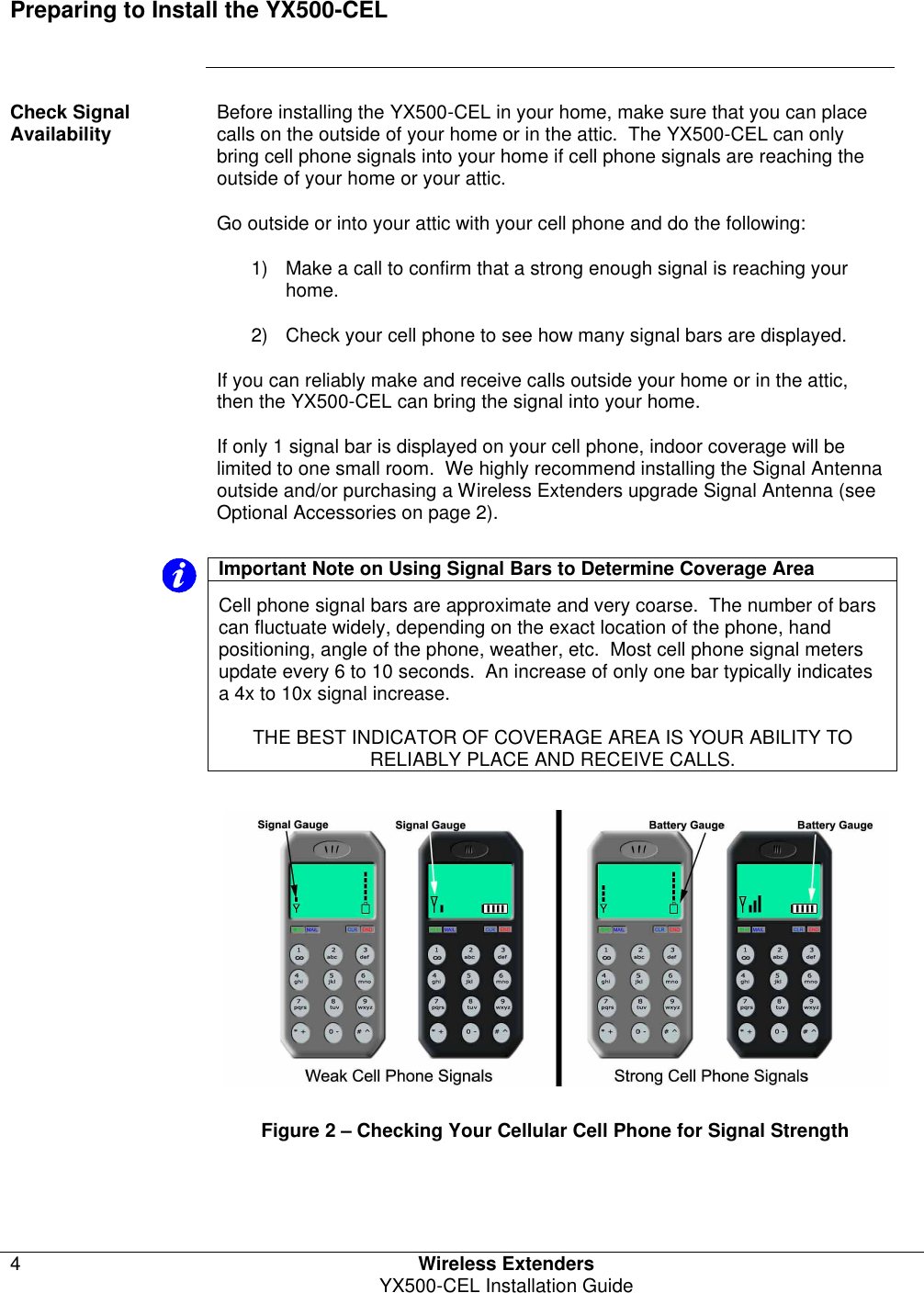
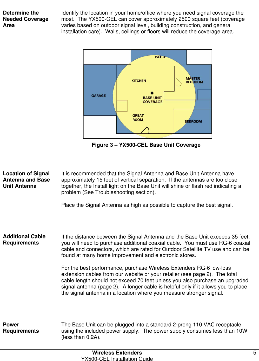
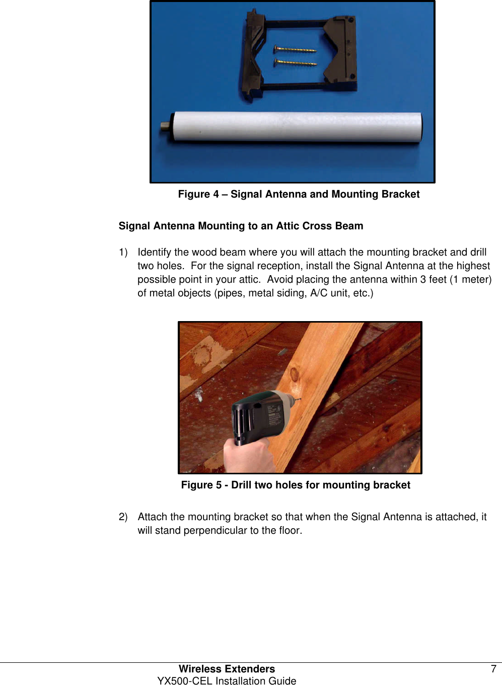
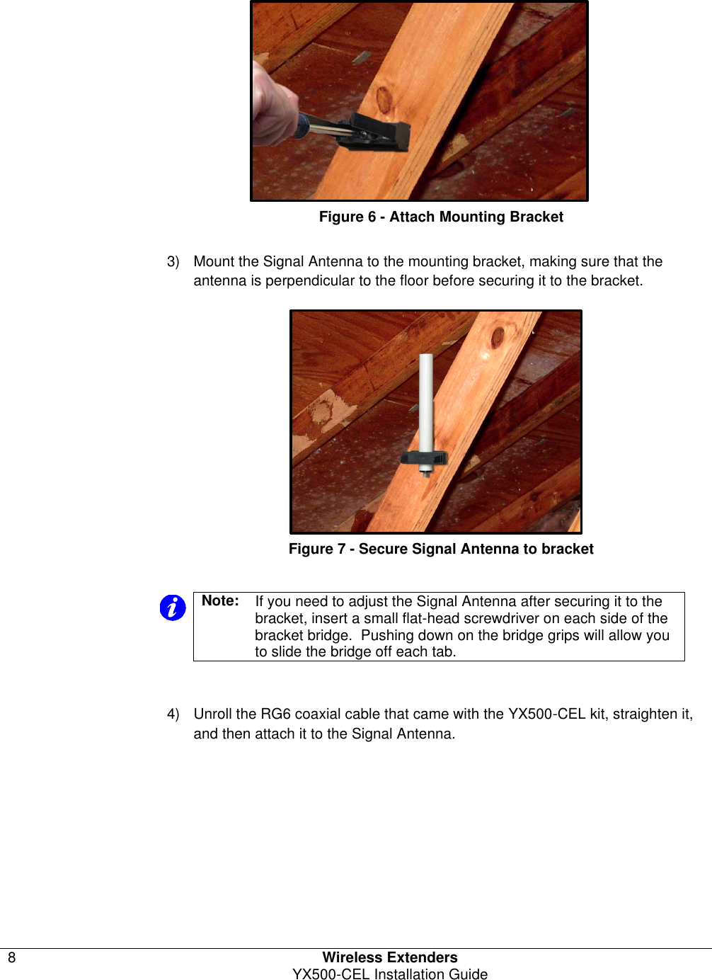
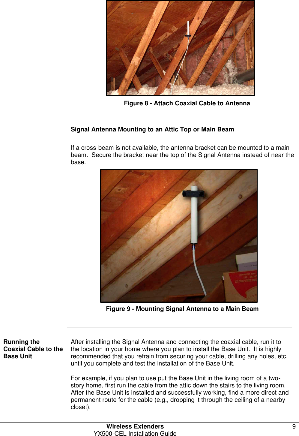
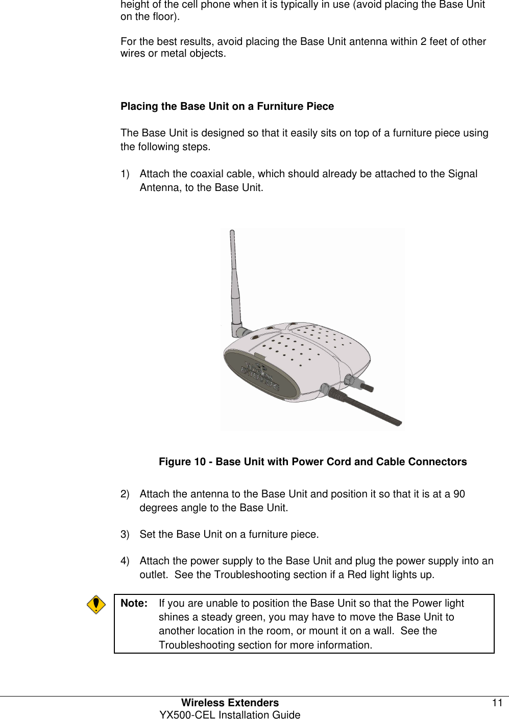
![Wireless Extenders Rev. A YX500-CEL Installation Guide Copyright Notice This manual is copyrighted. All rights reserved. This manual, whole or in part, may not be copied, photocopied, reproduced, translated, or reduced to any electronic medium or machine-readable form for distribution. This manual, whole or in part, may not be modified without prior consent, in writing, from Wireless Extenders. Copyright © 2005 by Wireless Extenders, Inc. 330 Research Court Suite 250, Norcross, GA 30092, U.S.A. Trademarks Wireless Extenders, the Wireless Extenders logo, and Wireless Where You Want It are registered trademarks of Wireless Extenders, Inc. iDEN is a registered trademark of Motorola. Nextel is a registered trademark of Nextel Communications Corp. FCC Information FCC ID: SO4YX500-CEL This equipment has been tested and found to comply with the limits for a Class B digital device, pursuant to Part 15 of the FCC Rules. These limits are designed to provide reasonable protection against harmful interference in the residential installation. This equipment generates, uses and can radiate radio frequency energy and, if not installed and used in accordance with the instructions, may cause harmful interference to radio communications. However, there is no guarantee that interference will not occur in a particular installation. If this equipment does cause harmful interference to radio or television reception, which can be determined by turning the equipment off and on, the user is encouraged to try to correct the interference by one or more of the following measures: • Reorient or relocate the receiving antenna. • Increase the separation between the equipment and receiver. • Connect the equipment into an outlet on a circuit different from that to which the receiver is connected. • Consult the dealer or a professional installer for help. Industry Canada Regulations Canada IC: 5544A-YX500CEL This Class B digital apparatus meets all requirements of the Canadian Interference Causing Equipment Regulations. Operation is subject to the following two conditions: (1) this device may not cause harmful interference, and (2) this device must accept any interference received, including interference that may cause undesired operation. Cet appareillage numérique de la classe [B] répond à toutes les exigences de l'interférence canadienne causant des règlements d'équipement. L'opération est sujette aux deux conditions suivantes: (1) ce dispositif peut ne pas causer l'interférence nocive, et (2) ce dispositif doit accepter n'importe quelle interférence reçue, y compris l'interférence qui peut causer l'opération peu désirée.](https://usermanual.wiki/zBoost/YX500-CEL/User-Guide-600728-Page-3.png)