zBoost YX500-CEL Cellular Bi-Directional Booster User Manual users manual
zBoost, LLC Cellular Bi-Directional Booster users manual
zBoost >
users manual

5015 B.U. Bowman Drive Buford, GA 30518 USA Voice: 770-831-8048 Fax: 770-831-8598
FCC Part 22 Transmitter Certification
Test Report
FCC ID: SO4YX500-CEL
FCC Rule Part: CFR 47 Part 22 Subpart H
ACS Report Number: 05-0343-22H
Manufacturer: Wireless Extenders
Equipment Type: Cellular Band Bi-Directional Booster
Model: YX500-CEL
Installation Guide
Rev. A
YX500-CEL
Installation Guide

Wireless Extenders
Rev. A YX500-CEL Installation Guide
Copyright Notice
This manual is copyrighted. All rights reserved. This manual, whole or in part, may not be copied,
photocopied, reproduced, translated, or reduced to any electronic medium or machine-readable form
for distribution. This manual, whole or in part, may not be modified without prior consent, in writing,
from Wireless Extenders.
Copyright © 2005 by Wireless Extenders, Inc. 330 Research Court Suite 250, Norcross, GA 30092,
U.S.A.
Trademarks
Wireless Extenders, the Wireless Extenders logo, and Wireless Where You Want It are registered
trademarks of Wireless Extenders, Inc.
iDEN is a registered trademark of Motorola.
Nextel is a registered trademark of Nextel Communications Corp.
FCC Information
FCC ID: SO4YX500-CEL
This equipment has been tested and found to comply with the limits for a Class B digital device,
pursuant to Part 15 of the FCC Rules. These limits are designed to provide reasonable protection
against harmful interference in the residential installation. This equipment generates, uses and can
radiate radio frequency energy and, if not installed and used in accordance with the instructions, may
cause harmful interference to radio communications. However, there is no guarantee that interference
will not occur in a particular installation. If this equipment does cause harmful interference to radio or
television reception, which can be determined by turning the equipment off and on, the user is
encouraged to try to correct the interference by one or more of the following measures:
• Reorient or relocate the receiving antenna.
• Increase the separation between the equipment and receiver.
• Connect the equipment into an outlet on a circuit different from that to which the receiver is
connected.
• Consult the dealer or a professional installer for help.
Industry Canada Regulations
Canada IC: 5544A-YX500CEL
This Class B digital apparatus meets all requirements of the Canadian Interference Causing Equipment
Regulations. Operation is subject to the following two conditions: (1) this device may not cause harmful
interference, and (2) this device must accept any interference received, including interference that may
cause undesired operation.
Cet appareillage numérique de la classe [B] répond à toutes les exigences de l'interférence
canadienne causant des règlements d'équipement. L'opération est sujette aux deux conditions
suivantes: (1) ce dispositif peut ne pas causer l'interférence nocive, et (2) ce dispositif doit accepter
n'importe quelle interférence reçue, y compris l'interférence qui peut causer l'opération peu désirée.
Wireless Extenders i
YX500-CEL Installation Guide Rev. A
Read First Before Installing the YX500-CEL
YX500-CEL For Cell
Phones Operating
on Cellular 800MHZ
Frequencies Only
Before unpacking this box, verify that your phone operates on Cellular 800MHz
frequencies. The YX500-CEL will enhance your in-building coverage for local
provider networks operating at the 800MHz (Cellular) frequency.
To verify that your phone uses Cellular 800MHz frequencies, please follow
these four simple steps:
1) Unpack the Base Unit and the Base Unit power supply only.
2) Connect the power supply to the Base Unit and plug it into an outlet. All of
the lights will flash for several seconds. The Power light should now be solid
green.
3) While standing about 1 foot away from the Base Unit, turn on your cell phone
or make a call. If the Signal light begins flashing green, you can proceed
with the installation of the YX500. If it flashes red, move your phone away
from the Base Unit (typical for GSM).
4) If the Signal light does not flash green, try to place another call with your cell
phone directly touching the YX500 (typical for CDMA). If the Signal light still
does not flash green, your cell phone may not be compatible with the YX500-
CEL. Contact Wireless Extenders technical support at 1-800-871-1612 for
further assistance.
Note:
The YX500 is fully automatic. The Install, Signal, and Power
lights on the Base Unit are not buttons. There are no buttons
to press on the Base Unit.
ii Wireless Extenders
YX500-CEL Installation Guide
Safety and Product Warranty Information
Safety Guidelines Please adhere to the following safety guidelines during the installation of the
YX500-CEL.
1) In accordance with FCC requirements of human exposure to radiofrequency
fields, the radiating element (antenna) shall be installed such that a minimum
separation distance of 8 inches (20cm) is maintained between the radiating
element and the user and/or general population.
2) If a ladder is required to install the YX500, make sure that the ladder feet are
on a flat surface and the ladder is securely fixed. It is highly recommended
that you have someone assist you while you are on the ladder.
3) You should always wear proper eye protection when working with power
tools.
4) Keep all plastic bags away from children to avoid suffocation hazard.
5) Before drilling make sure you know where existing electrical wiring is so as
not to hit the wiring, which could cause an electrical shock and severe the
wiring.
Limited Liability In no event shall Wireless Extenders be liable for any direct, indirect, special,
punitive, incidental, exemplary or consequential damages, or any damages,
whether in an action under contract, negligence, or any other theory, arising
out of or in connection with the installation of, use of, inability to use, or
performance of the information, services, products, and materials available
from this manual. These limitations shall apply notwithstanding any failure of
essential purpose of any limited remedy. Because some jurisdictions do not
allow limitations on how long an implied warranty last, or the exclusion or
limitation of liability for consequential or incidental damages, the above
limitations may not apply to you.
Technical Support If you have any problems with the operation of your YX500 please visit our
website http://www.WirelessExtenders.com or contact Wireless Extenders
customer support at 1-800-871-1612 for assistance.
Warning: Changes or modifications not expressly approved by
Wireless Extenders could void the user’s authority to
operate this equipment and/or void the product warranty.

Wireless Extenders iii
YX500-CEL Installation Guide Rev. A
Outdoor Installation of the Signal Antenna
Grounding the
Signal Antenna If you decide to install the Signal Antenna outdoors, it must be properly
grounded. This will help protect your property against lightning strikes during a
lightning storm.
The installation must be in accordance with Article 810 of the National Electric
Code (NEC). A listed antenna discharge unit must be provided for the lead-in
coaxial cable per NEC article 8.10.20 or the shield of the coaxial cable must be
permanently and effectively grounded in accordance with NEC article 8.10.21.
Please consult a professional installer or electrician for more information.
Additional instructions and hardware are also available in the Wireless
Extenders Outdoor Installation and Grounding Kit (Part# YX011).
Securing Cable with
a Drip Loop If you install the Signal Antenna outdoors, create a drip loop with the coaxial
cable at the point where the cable enters the building through an outside wall.
This can be done by twisting and securing the cable into a loop (no less than
4” across) near the entry point. This will help prevent moisture from gathering
at entry point and leaking into the building. Consult a professional installer if
you need more information. Additional instructions are also available in the
Wireless Extenders Outdoor Installation and Grounding Kit (Part# YX011).
Avoid Drilling or
Nailing into the
Roof
Avoid any drilling or nailing directly into the roof. This could allow water to leak
into your home and cause damage.

iv Wireless Extenders
YX500-CEL Installation Guide
This Page Intentionally Left Blank

Table of Contents
Wireless Extenders v
YX500-CEL Installation Guide Rev. A
Read First Before Installing the YX500-CEL.................................................................i
YX500-CEL For Cell Phones Operating on Cellular 800MHZ Frequencies Only.................i
Safety and Product Warranty Information...................................................................ii
Safety Guidelines ..................................................................................................................ii
Limited Liability .....................................................................................................................ii
Technical Support .................................................................................................................ii
Outdoor Installation of the Signal Antenna................................................................iii
Package Contents .........................................................................................................1
Accessories - Improve your coverage.........................................................................2
YX500-CEL Product Overview......................................................................................3
Overview ................................................................................................................................3
Why Signals Can be Weak ....................................................................................................3
Preparing to Install the YX500-CEL..............................................................................4
Check Signal Availability ......................................................................................................4
Determine the Needed Coverage Area.................................................................................5
Location of Signal Antenna and Base Unit Antenna...........................................................5
Additional Cable Requirements............................................................................................5
Power Requirements.............................................................................................................5
Installation Tools...................................................................................................................6
Installing the YX500-CEL ..............................................................................................6
Installing the Signal Antenna................................................................................................6
Attic Installation of the Signal Antenna ...............................................................................6
Running the Coaxial Cable to the Base Unit.......................................................................9
Additional Cable Requirements..........................................................................................10
Installing the Base Unit.......................................................................................................10
Confirm that the YX500-CEL is Working Properly.............................................................12
Improving Your Coverage Area ..........................................................................................13
Troubleshooting the YX500-CEL................................................................................14
Base Unit Light Operation...................................................................................................14
YX500-CEL Technical Specifications.........................................................................15

vi Wireless Extenders
YX500-CEL Installation Guide
This Page Intentionally Left Blank
Wireless Extenders 1
YX500-CEL Installation Guide
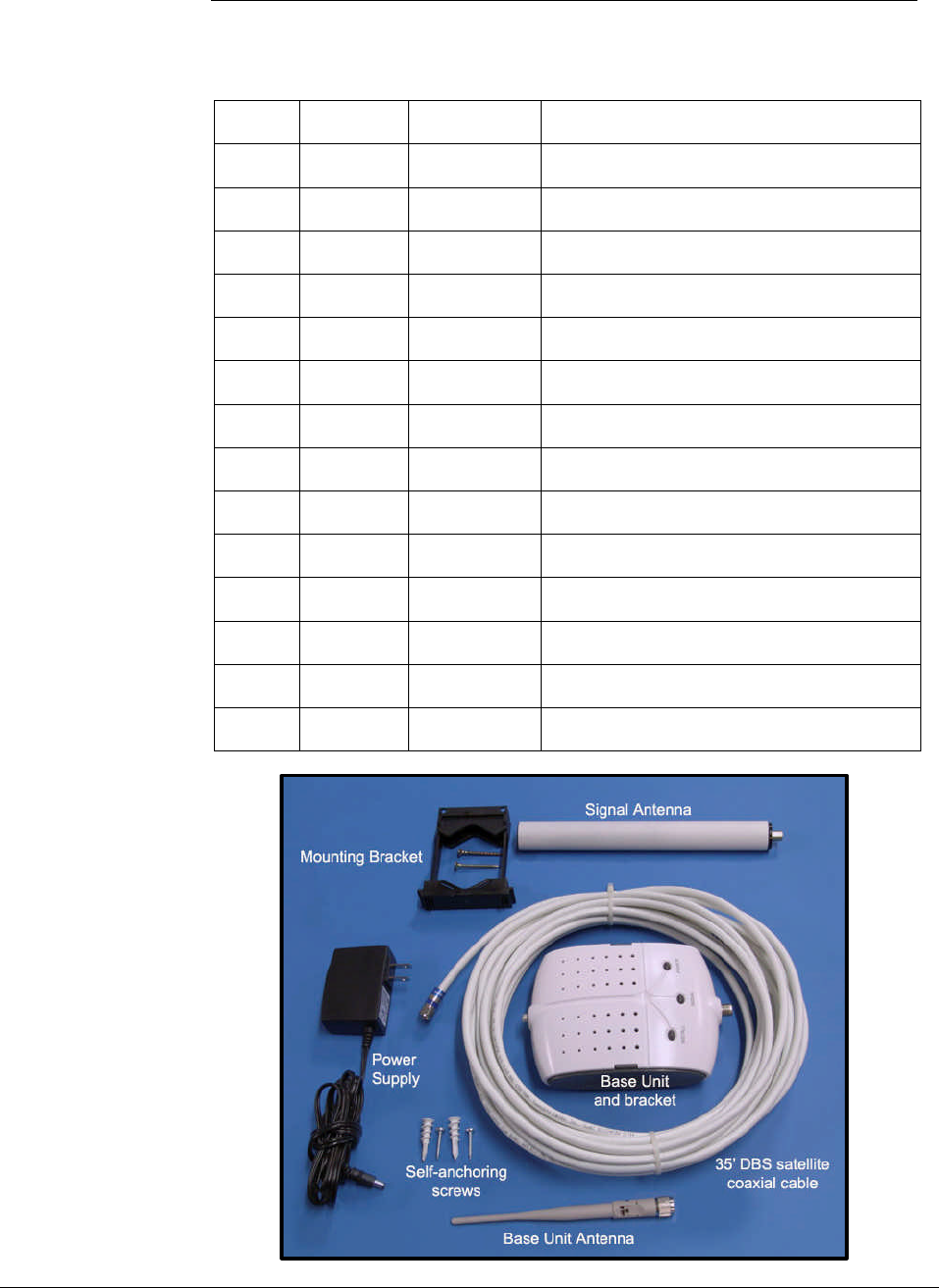
Package
Contents Before you begin, make sure all of the following parts came with your kit:
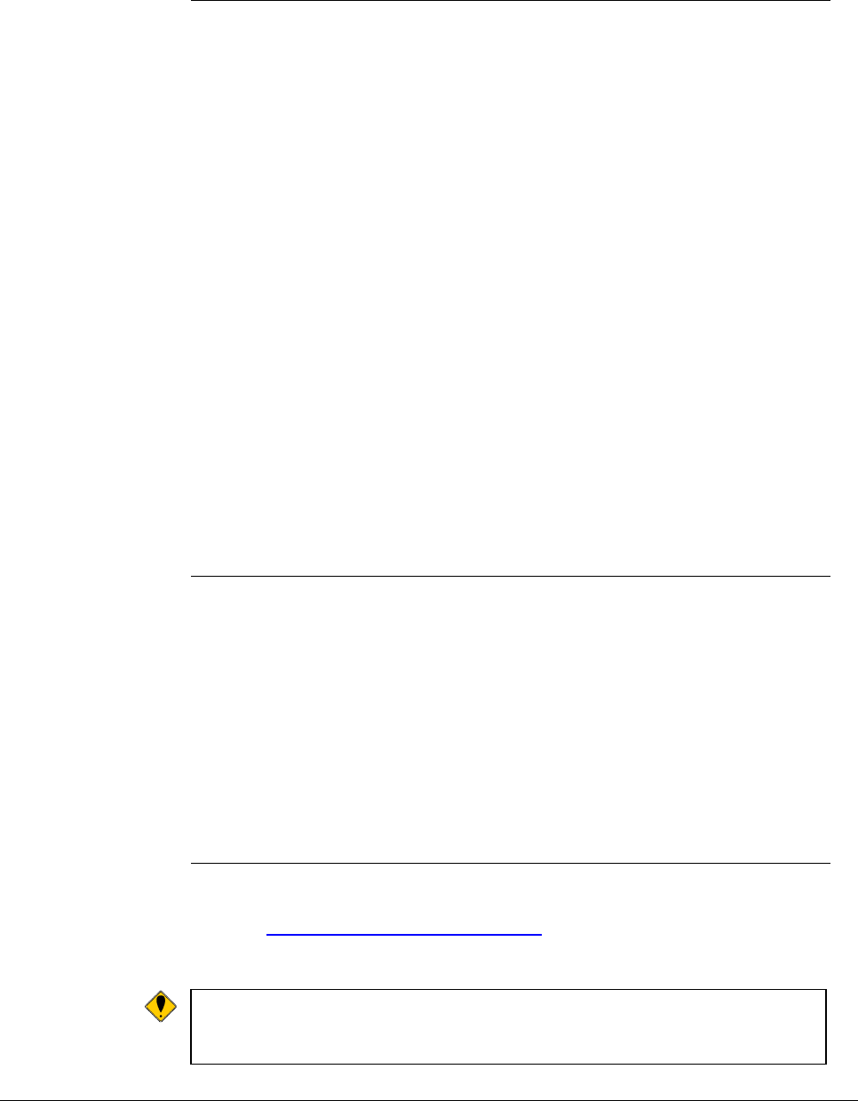
Item Quantity Part # Description
1
1 DMAN-0009 Before Unpacking Sheet
2
1 DMAN-0008 Installation Overview Poster
3
1 DMAN-0010 YX500-CEL Installation Guide
4
1 APRD-0003 YX500-CEL Base Unit
5
1 CPSP-0001
YX500 - Base Unit Power Supply
6
4 CHDW-0007
YX500 - Base Unit rubber feet
7
1 FHSG-0004 YX500 - Base Unit Bracket
8
1 CANT-0010 0dBi YX500-CEL Base Unit Antenna
9
1 CANT-0009 3dBi YX500-CEL Signal Antenna
10
1 CHDW-0008
Signal Antenna mounting bracket
11
1 CCBL-0001 35' white, DBS satellite coaxial cable
12
2 CHDW-0001
Self-tapping #6 x 7/8" Philips Screw
13
2 CHDW-0002
Self-tapping #6 Sheet Rock Anchor
14
2 CHDW-0005
Wood Screw #6 x 1" Philips
2 Wireless Extenders
YX500-CEL Installation Guide
Accessories - Improve your coverage
The following accessories are also available to improve signal reception and
provide increased coverage in your home or office or improve installation.
To order, call 1-800-871-1612 or visit, www.WirelessExtenders.com.
Part # Description
YX010 Professional Installation
YX011 Outdoor Installation and Grounding Kit
YX013 Wall mounting bracket for the YX023
YX022-CEL 6dBi Omni Signal Antenna upgrade – 2 feet long
YX023-CEL 8dBi Directional Signal Antenna upgrade – Flat Panel
YX024-CEL 5dBi Directional Base Unit Antenna upgrade
YX025-CEL 7dBi Directional Signal Antenna upgrade – 14” Yagi
YX030-15W 15 ft. outdoor coax extension cable, white, low-loss RG-6
YX030-35W 35 ft. outdoor coax extension cable, white, low-loss RG-6
YX031-10W 10 ft. Base Unit antenna extension cable, white, low-loss
YX040-N50 2-way indoor signal splitter. Connect 2 antennas to one
Base Unit to cover 2 separated areas – does not increase
total coverage. Use with any YX500 system
Wireless Extenders 3
YX500-CEL Installation Guide
YX500-CEL Product Overview
Overview Thank you for selecting the Wireless Extenders YX500-CEL. With the YX500-
CEL, you will now be able to use your cell phone INSIDE your home or office.
Gone are the days when you have to go to the window upstairs or walk outside
to get enough signal. Like a skylight that brings sunlight into your home, the
YX500-CEL transports and amplifies the outdoor cellular, 800MHz, signals into
your home or office.
By following the easy instructions in this installation guide, you will soon be
enjoying Wireless Where You Want It™.
Why Signals Can be
Weak There are several obstacles that can contribute to the poor reception you
receive in your home or office:
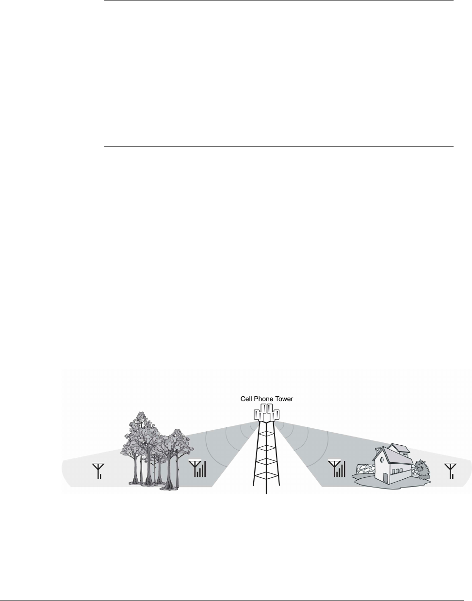
Proximity of the Cell Phone Tower to your Home/Office
Unlike the sun, cell phone signals do not fill the sky from every direction. While
cell phone providers have tried to strategically install cell phone towers to provide
the best overall coverage, local ordinances and nature (e.g., lakes) can impose
restrictions on where these towers can be placed.
Obstructions Caused by Buildings and Land Masses
Like the sun when it sits low in the sky during early morning and late afternoon,
cell phone signals can be completely blocked or deflected by buildings, the walls
of the building you are in, clusters of trees, hills, etc.
Figure 1
4 Wireless Extenders
YX500-CEL Installation Guide
Preparing to Install the YX500-CEL
Check Signal
Availability Before installing the YX500-CEL in your home, make sure that you can place
calls on the outside of your home or in the attic. The YX500-CEL can only
bring cell phone signals into your home if cell phone signals are reaching the
outside of your home or your attic.
Go outside or into your attic with your cell phone and do the following:
1) Make a call to confirm that a strong enough signal is reaching your
home.
2) Check your cell phone to see how many signal bars are displayed.
If you can reliably make and receive calls outside your home or in the attic,
then the YX500-CEL can bring the signal into your home.
If only 1 signal bar is displayed on your cell phone, indoor coverage will be
limited to one small room. We highly recommend installing the Signal Antenna
outside and/or purchasing a Wireless Extenders upgrade Signal Antenna (see
Optional Accessories on page 2).
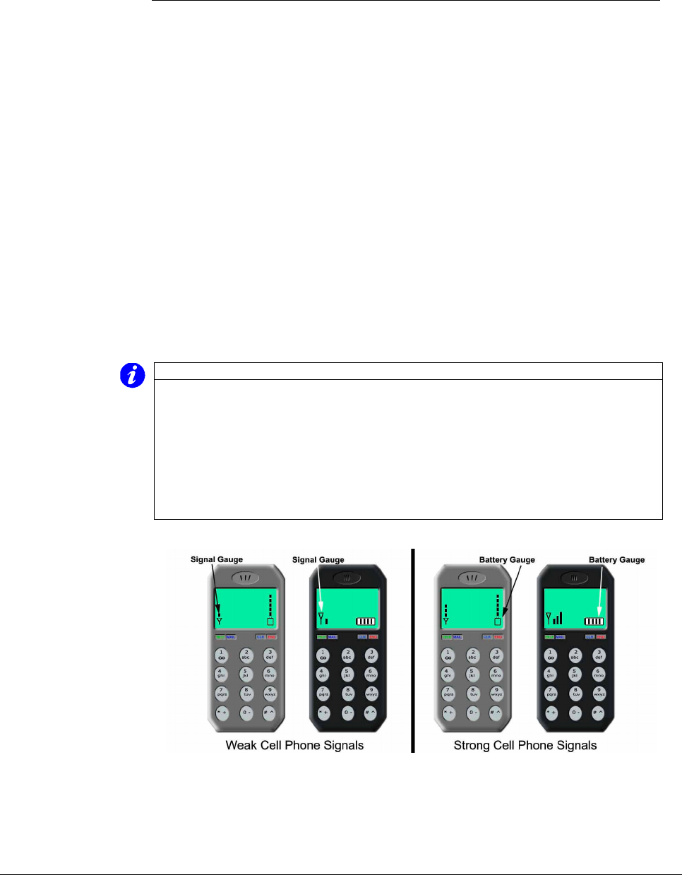
Important Note on Using Signal Bars to Determine Coverage Area
Cell phone signal bars are approximate and very coarse. The number of bars
can fluctuate widely, depending on the exact location of the phone, hand
positioning, angle of the phone, weather, etc. Most cell phone signal meters
update every 6 to 10 seconds. An increase of only one bar typically indicates
a 4x to 10x signal increase.
THE BEST INDICATOR OF COVERAGE AREA IS YOUR ABILITY TO
RELIABLY PLACE AND RECEIVE CALLS.
Figure 2 – Checking Your Cellular Cell Phone for Signal Strength
Wireless Extenders 5
YX500-CEL Installation Guide
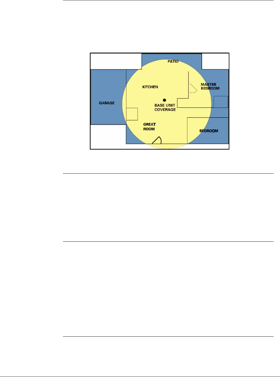
Determine the
Needed Coverage
Area
Identify the location in your home/office where you need signal coverage the
most. The YX500-CEL can cover approximately 2500 square feet (coverage
varies based on outdoor signal level, building construction, and general
installation care). Walls, ceilings or floors will reduce the coverage area.
Figure 3 – YX500-CEL Base Unit Coverage
Location of Signal
Antenna and Base
Unit Antenna
It is recommended that the Signal Antenna and Base Unit Antenna have
approximately 15 feet of vertical separation. If the antennas are too close
together, the Install light on the Base Unit will shine or flash red indicating a
problem (See Troubleshooting section).
Place the Signal Antenna as high as possible to capture the best signal.
Additional Cable
Requirements If the distance between the Signal Antenna and the Base Unit exceeds 35 feet,
you will need to purchase additional coaxial cable. You must use RG-6 coaxial
cable and connectors, which are rated for Outdoor Satellite TV use and can be
found at many home improvement and electronic stores.
For the best performance, purchase Wireless Extenders RG-6 low-loss
extension cables from our website or your retailer (see page 2). The total
cable length should not exceed 70 feet unless you also purchase an upgraded
signal antenna (page 2). A longer cable is helpful only if it allows you to place
the signal antenna in a location where you measure stronger signal.
Power
Requirements The Base Unit can be plugged into a standard 2-prong 110 VAC receptacle
using the included power supply. The power supply consumes less than 10W
(less than 0.2A).
6 Wireless Extenders
YX500-CEL Installation Guide
Warning: The YX500-CEL base unit MUST only be used with the
provided power adaptor. Attempts to use other power
adaptors will void the warranty and is not FCC approved.
Installation Tools
The following tools are needed to install the YX500-CEL:
• #2 Philips screwdriver
• Cordless drill
• Cellular phone operating in 800 MHz band
Installing the YX500-CEL
Installing the Signal
Antenna There are four options available for installing the Signal Antenna:
1. Install the Signal Antenna in the attic using the accessories included in the
YX500-CEL kit (an attic installation is not recommended if the outside cell
phone signal test yielded less than 2 signal bars).
2. Install the Signal Antenna outside using the optional Outdoor Installation
and Grounding kit ( Part# YX011 )
3. Install the Signal Antenna outside using parts and accessories that can be
purchased at a home improvement or electronics store.
4. Call 1-800-871-1612 to arrange for a professional installation.
Warning: Avoid placing antenna near metal such as wiring, A/C ducts, truss
plates, etc.
When attaching the cable to the antenna, run the cable straight
down from the antenna. Avoid draping the coax near the antenna.
Attic Installation of
the Signal Antenna Once you have confirmed that you have a cell phone signal either outside your
home or inside your attic, you are ready to install the Signal Antenna using the
supplied mounting brackets, Signal Antenna, and coaxial cable.
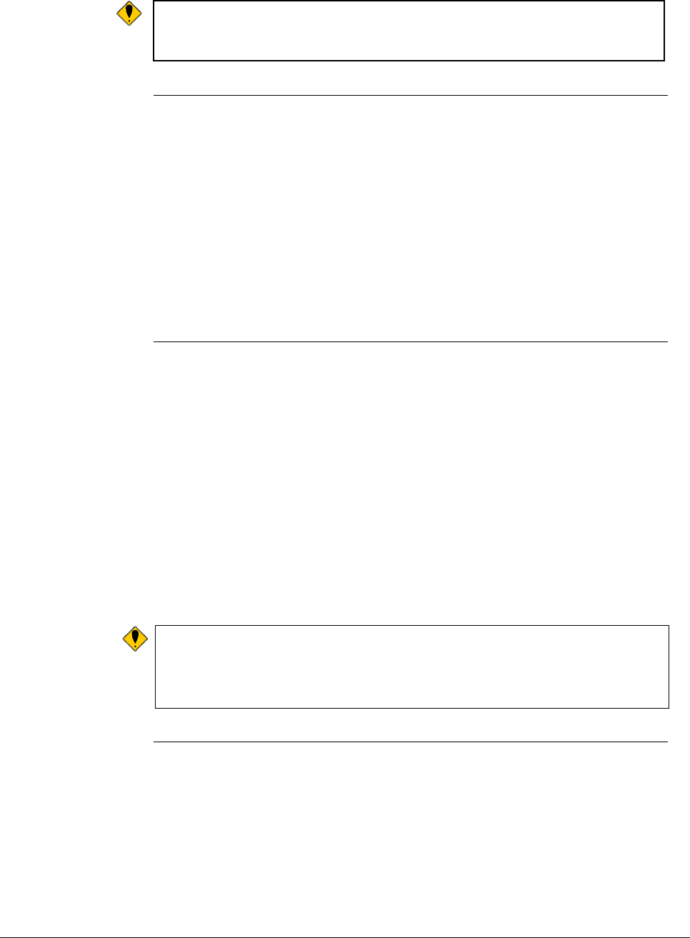
Wireless Extenders 7
YX500-CEL Installation Guide
Figure 4 – Signal Antenna and Mounting Bracket
Signal Antenna Mounting to an Attic Cross Beam
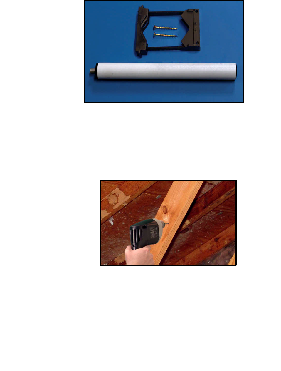
1) Identify the wood beam where you will attach the mounting bracket and drill
two holes. For the signal reception, install the Signal Antenna at the highest
possible point in your attic. Avoid placing the antenna within 3 feet (1 meter)
of metal objects (pipes, metal siding, A/C unit, etc.)
Figure 5 - Drill two holes for mounting bracket
2) Attach the mounting bracket so that when the Signal Antenna is attached, it
will stand perpendicular to the floor.
8 Wireless Extenders
YX500-CEL Installation Guide
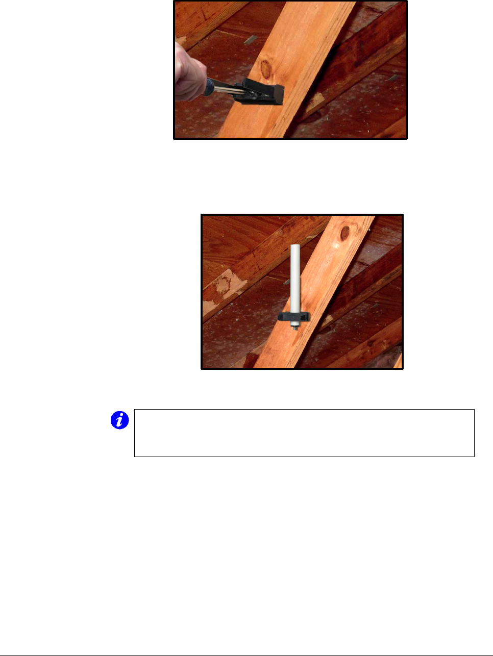
Figure 6 - Attach Mounting Bracket
3) Mount the Signal Antenna to the mounting bracket, making sure that the
antenna is perpendicular to the floor before securing it to the bracket.
Figure 7 - Secure Signal Antenna to bracket
Note:
If you need to adjust the Signal Antenna after securing it to the
bracket, insert a small flat-head screwdriver on each side of the
bracket bridge. Pushing down on the bridge grips will allow you
to slide the bridge off each tab.
4) Unroll the RG6 coaxial cable that came with the YX500-CEL kit, straighten it,
and then attach it to the Signal Antenna.
Wireless Extenders 9
YX500-CEL Installation Guide
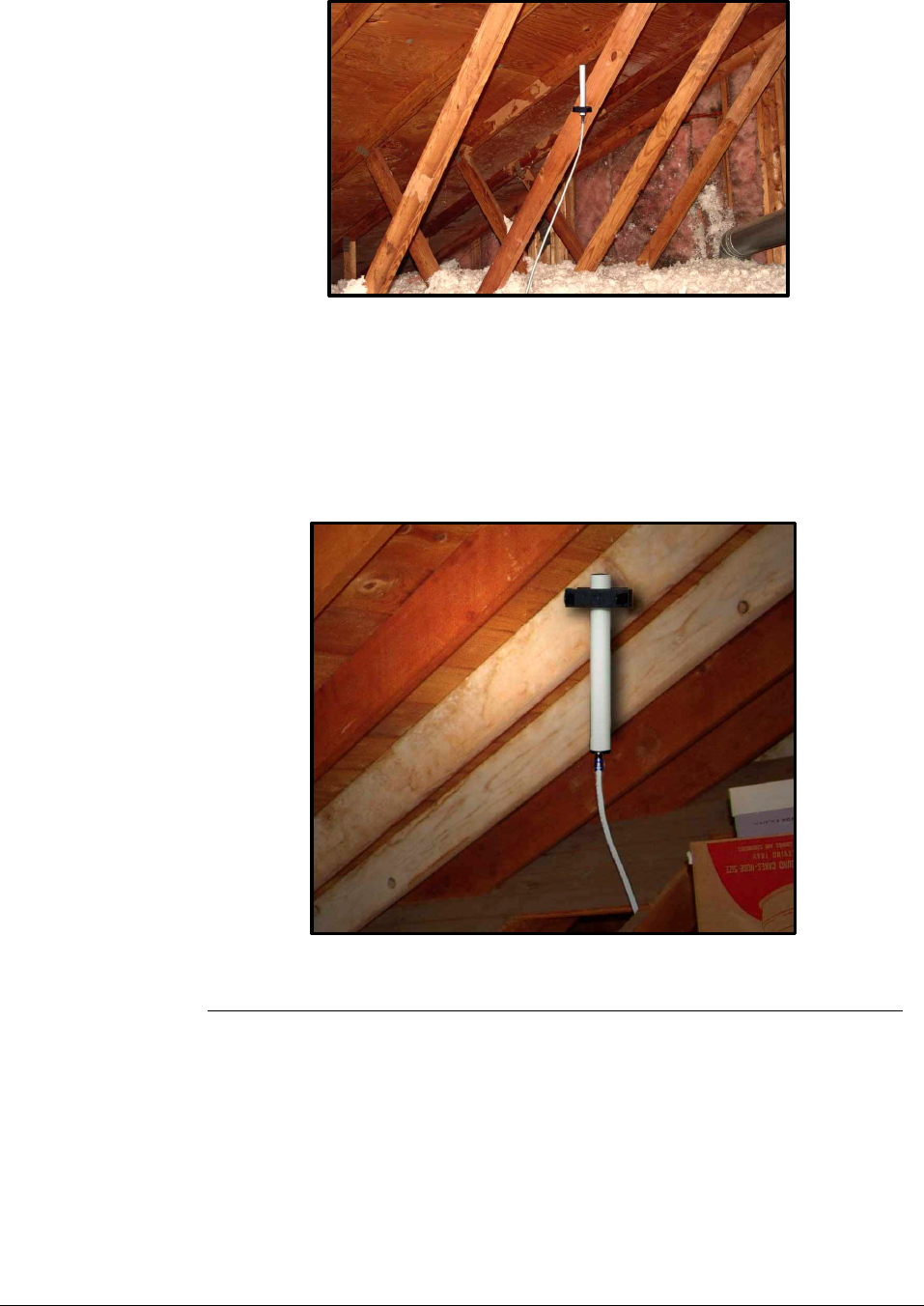
Figure 8 - Attach Coaxial Cable to Antenna
Signal Antenna Mounting to an Attic Top or Main Beam
If a cross-beam is not available, the antenna bracket can be mounted to a main
beam. Secure the bracket near the top of the Signal Antenna instead of near the
base.
Figure 9 - Mounting Signal Antenna to a Main Beam
Running the
Coaxial Cable to the
Base Unit
After installing the Signal Antenna and connecting the coaxial cable, run it to
the location in your home where you plan to install the Base Unit. It is highly
recommended that you refrain from securing your cable, drilling any holes, etc.
until you complete and test the installation of the Base Unit.
For example, if you plan to use put the Base Unit in the living room of a two-
story home, first run the cable from the attic down the stairs to the living room.
After the Base Unit is installed and successfully working, find a more direct and
permanent route for the cable (e.g., dropping it through the ceiling of a nearby
closet).
10 Wireless Extenders
YX500-CEL Installation Guide
Additional Cable
Requirements If the distance between the Signal Antenna and the Base Unit exceeds 35 feet,
you will need to purchase additional coaxial cable. You must use RG-6 coaxial
cable and connectors, which are rated for Outdoor Satellite TV use and can be
found at many home improvement and electronic stores.
For the best performance, purchase Wireless Extenders RG-6 extension
cables from our website or your retailer (see page 2). The total cable length
should not exceed 70 feet unless you also purchase an upgraded signal
antenna (page 2). A longer cable is helpful if it allows you to place the signal
antenna in a location where you measure stronger signal.
Caution: Before drilling any holes into a wall to run your cable, make sure
you know where existing electrical wiring is located. If you are not
careful, hitting wiring while drilling could cause an electrical shock
and severe the wire.
Routing the Coaxial Cable Alongside an Attic Pipe
To simply the effort needed to route the coaxial cable from the Signal Antenna to
the Base Unit, Wireless Extenders recommends the following procedure:
1) Locate a pipe which descends from the attic down to a location in or near the
room where signal coverage is desired.
2) Tie a weight to a pull string and lower the weight down alongside the pipe.
3) In the lower room, tie the pull-string onto one end of the cable.
4) Go back to the attic and gently pull up the string until the coaxial cable can
be grasped.
5) Connect the coaxial cable to the Signal Antenna.
Installing the Base
Unit For the widest possible signal reception, it recommended that you install the
YX500-CEL Base Unit near the middle of a room or on an interior wall. This is
because the Base Unit uses an omni-directional antenna, which like a lantern
delivers the signal in a circular pattern around the antenna. If you decide to
install the Base Unit on or near an outside wall, we recommend purchasing a
Directional Base Unit Antenna (see page 2). This antenna will focus the signal
in towards the rooms.
The Base Unit can either be directly mounted on a wall or set on a furniture
piece (e.g., a bookshelf, desk, filing cabinet, end table etc.). The Base Unit
performs best when located at least 4 feet above the floor or at about the
Wireless Extenders 11
YX500-CEL Installation Guide
height of the cell phone when it is typically in use (avoid placing the Base Unit
on the floor).
For the best results, avoid placing the Base Unit antenna within 2 feet of other
wires or metal objects.
Placing the Base Unit on a Furniture Piece
The Base Unit is designed so that it easily sits on top of a furniture piece using
the following steps.
1) Attach the coaxial cable, which should already be attached to the Signal
Antenna, to the Base Unit.
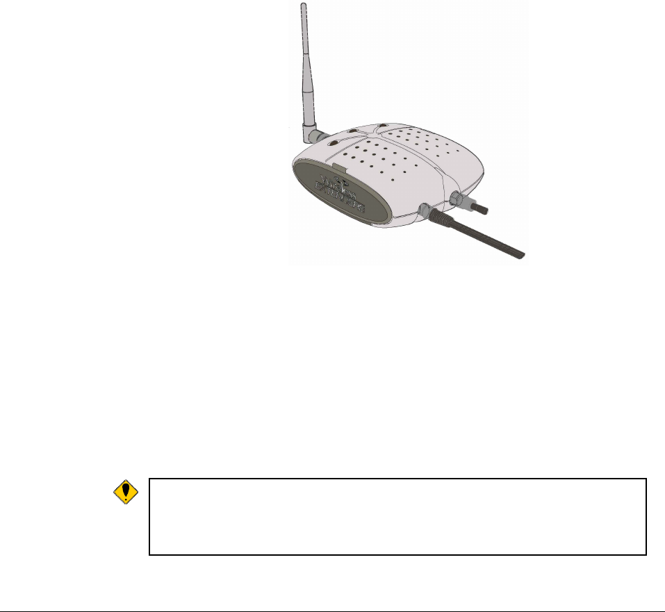
Figure 10 - Base Unit with Power Cord and Cable Connectors
2) Attach the antenna to the Base Unit and position it so that it is at a 90
degrees angle to the Base Unit.
3) Set the Base Unit on a furniture piece.
4) Attach the power supply to the Base Unit and plug the power supply into an
outlet. See the Troubleshooting section if a Red light lights up.
Note: If you are unable to position the Base Unit so that the Power light
shines a steady green, you may have to move the Base Unit to
another location in the room, or mount it on a wall. See the
Troubleshooting section for more information.
12 Wireless Extenders
YX500-CEL Installation Guide
Wall Mounting the Base Unit
The Base Unit can also be easily mounted on a wall using the included mounting
bracket hardware. The Base Unit should be a minimum distance of 12" from the
ceiling so their is clearance for the Base Unit antenna extension.
Perform the following steps to mount the Base Unit on a wall:
1) Remove the mounting bracket from the Base Unit
2) Attach the coaxial cable, which should already be attached to the Signal
Antenna, to the Base Unit.
3) Attach the antenna to the Base Unit.
4) Attach the power supply to the Base Unit and plug the power supply into an
outlet. See the Troubleshooting section if a Red light lights up.
5) Holding the Base Unit, adjust its position on the wall until the LEDs shine a
steady green. The Base Unit can be mounted on the wall with the antenna
pointing to the ceiling or towards the floor.
6) Fasten the mounting bracket to the wall using the self-tapping wall/ceiling
anchors
7) Snap the Base Unit into the mounting bracket.
Note:
If you are unable to position the Base Unit so that the Power light
shines a steady green, you may have to move the Base Unit to
another wall in the room.
Confirm that the
YX500-CEL is
Working Properly
Perform the following steps to confirm that the YX500-CEL is now working
properly:
1) Unplug the YX500-CEL Base Unit power cord.
2) Turn on your Cellular cell phone and check the signal meter.
3) Turn off your Cellular cell phone.
4) Plug-in the YX500-CEL Base Unit power cord.
5) Hold your Cellular cell phone about 2 to 3 feet from the Base Unit and
then turn it on. Wait up to 1 minute for the cell phone to register the
signal coming from the Base Unit.
6) If the signal meter shows an improvement, the YX500-CEL is working
properly. You now have Wireless Where You Want It™.
Wireless Extenders 13
YX500-CEL Installation Guide
Note:
The Signal light may flash green indicating that a call is in progress and
the YX500-CEL is boosting your signal. In some cases, it may only
flash at the beginning of the call.
If the Signal light displays either a solid or flashing red move your
phone away from the Base Unit and see the troubleshooting section.
Improving Your
Coverage Area Now that everything is connected and the Base Unit is plugged in, you should
walk throughout the room and see that you are able to reliably place calls.
Remember, coverage varies based on outdoor signal level, building
construction, and general installation care). Coverage in adjoining rooms (next
to, above, or below) will be reduced due to the walls or the ceiling/floor.
Should you desire to improve coverage, you may:
1) Move the Base Unit and/or bend the antenna 90 degrees
2) Move the Signal Antenna to a higher location in your attic or outside
3) Purchase a Signal Antenna Upgrade (see Page 2)
4) Purchase a Base Unit Antenna Upgrade (see Page 2).
Important Note on Using Signal Bars to Determine Coverage Area
Cell phone signal bars are approximate and very coarse. The number of bars
can fluctuate widely, depending on the exact location of the phone, hand
positioning, angle of the phone, weather, etc. Most cell phone signal meters
update every 6 to 10 seconds. An increase of only one bar typically indicates
a 4x to 10x signal increase.
THE BEST INDICATOR OF COVERAGE AREA IS YOUR ABILITY TO
RELIABLY PLACE AND RECEIVE CALLS.
14 Wireless Extenders
YX500-CEL Installation Guide
Troubleshooting the YX500-CEL
Base Unit Indicator
Operation In most cases, problems with the YX500-CEL can be diagnosed using the
Base Unit’s LED indicators.
Mode Light Settings Action
Normal / Idle Power light = Solid Green
Signal light = Off
Install light = Off
None
Call Detected Power light = Solid Green
Signal light = Green
Install light = Off
None
May only Flash at the beginning of a call.
Base Unit Setup Power light = Flashing Green
Signal light = Flashing Orange
Install light = Flashing Red
Occurs when the Base Unit is first powered on to
initialize the unit and detect proper installation.
May occur if the installation is compromised. If
this state is observed multiple times, please call
for technical support.
Oscillation –
Reduced Range Power light = Solid Green
Signal light = Off
Install light = Flashing Red (20
seconds)
An oscillation was detected. The Base Unit has
corrected it, but is operating with reduced range.
You must move the antenna(s) to increase
separation. You may cycle power to re-check for
this condition.
Oscillation – Base
Unit Shutdown
(Temporary)
Power light = Off
Signal light = Off
Install light = Solid Red
None. Base Unit will attempt to correct itself
within 1 minute.
Oscillation – Base
Unit Shutdown
(Permanent until
power is cycled)
Power light = Off
Signal light = Flashing Red
Install light = Flashing Red
You must cycle power to the Base Unit and
review the light indicators. An oscillation was
detected but the Base Unit is unable to correct it.
You must move the antenna(s) to increase
separation and then cycle power.
User Caution Power light = Solid Green
Signal light = Flashing Red
Install light = Off
User’s phone/device is very close to the Base
Unit. Move the phone/device away from the
Base Unit to avoid User Shutdown.
User Shutdown Power light = Off
Signal light = Solid Red
Install light = Off
User’s phone/device is too close to the Base
Unit. The Base Unit has temporarily shut down
to prevent network interference and protect itself.

Wireless Extenders 15
YX500-CEL Installation Guide
Mode Light Settings Action
Network Caution –
Reduced Range Power light = Solid Green
Signal light = Flashing Red (20
seconds)
Install light = Flashing Red (20
seconds)
The Signal Antenna is receiving too much signal
from a nearby cell tower (probably another
service provider) and the Base Unit is operating
with reduced gain (range). Try making one or
more of the following adjustments:
1. Slightly adjust the position angle of the Signal
Antenna (about 20-45 degrees from vertical) so
that it is pointing toward the closest tower.
2. Move the Signal Antenna to another part of the
attic.
3. Purchase and install a directional Signal
antenna (see page 2) to pull in your providers’
signal and not the closest tower’s signal.
4. Contact a professional installer for assistance.
Network Overdrive
– Base Unit
Shutdown
Power light = Off
Signal light = Solid Red
Install light = Solid Red
The Signal Antenna received an excessive signal
from a nearby cell tower (probably another
service provider) and the Base Unit shut down to
protect the network. Try one more of the
following to correct the problem:
See above: Network Caution – Reduced Range
YX500-CEL Technical Specifications
Frequency 824 - 894 MHz (Cellular only)
Networks: CDMA, GSM, TDMA, AMPS
Total Signal Gain: 56dB (adaptive)
RF Output Power: ½ Watt EiRP (with included antenna)
Base Unit Weight: 12 oz.
Base Unit Size: 5” x 7” x 2”
AC Power Input: 100 – 120 VAC 60Hz
DC Power Output: 5VDC, 1.5A
FCC ID: SO4YX500-CEL
Industry Canada ID: 5544A-YX500CEL
Patents pending