zBoost YX500-PCS PCS Band Bi-Directional Booster User Manual users manual
zBoost, LLC PCS Band Bi-Directional Booster users manual
UserManual.wiki
>
zBoost
>
YX500 PCS User Manual
users manual
Navigation menu
Upload a User Manual
Namespaces
Wiki Guide
HTML
PDF
Info
Views
User Manual
Discussion / Help
Navigation
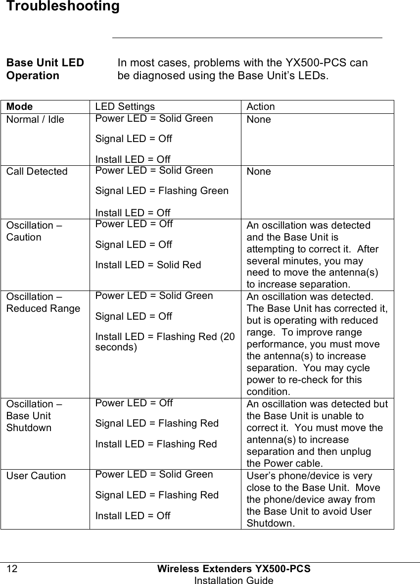
![Copyright Notice This manual is copyrighted. All rights reserved. This manual, whole or in part, may not be copied, photocopied, reproduced, translated, or reduced to any electronic medium or machine-readable form for distribution. This manual, whole or in part, may not be modified without prior consent, in writing, from Wireless Extenders. Copyright © 2004 by Wireless Extenders, 11450 Technology Circle, Duluth, GA 30097, U.S.A. Trademarks FCC Information FCC ID: SO4YX500-PCS This equipment has been tested and found to comply with the limits for a Class B digital device, pursuant to Part 15 of the FCC Rules. These limits are designed to provide reasonable protection against harmful interference in the residential installation. This equipment generates, uses and can radiate radio frequency energy and, if not installed and used in accordance with the instructions, may cause harmful interference to radio communications. However, there is no guarantee that interference will not occur in a particular installation. If this equipment does cause harmful interference to radio or television reception, which can be determined by turning the equipment off and on, the user is encouraged to try to correct the interference by one or more of the following measures: • Reorient or relocate the receiving antenna. • Increase the separation between the equipment and receiver. • Connect the equipment into an outlet on a circuit different from that to which the receiver is connected. • Consult the dealer or a professional installer for help. Industry Canada Regulations This Class [*] digital apparatus meets all requirements of the Canadian Interference Causing Equipment Regulations. Operation is subject to the following two conditions: (1) this device may not cause harmful interference, and (2) this device must accept any interference received, including interference that may cause undesired operation. Cet appareillage numérique de la classe [*] répond à toutes les exigences de l'interférence canadienne causant des règlements d'équipement. L'opération est sujette aux deux conditions suivantes: (1) ce dispositif peut ne pas causer l'interférence nocive, et (2) ce dispositif doit accepter n'importe quelle interférence reçue, y compris l'interférence qui peut causer l'opération peu désirée. Repairs and Replacements Repair and Replacement Requests during Limited Warranty Period During the Limited Warranty Period, Wireless Extenders will repair or replace (at Wireless Extenders discretion), without charge to the purchaser, any defective system components, provided that the system is returned promptly upon discovery of the defect while the product is still under warranty. To obtain service, the system must be: {What is Wireless Extender’s return and repair policy?}](https://usermanual.wiki/zBoost/YX500-PCS/User-Guide-499328-Page-3.png)

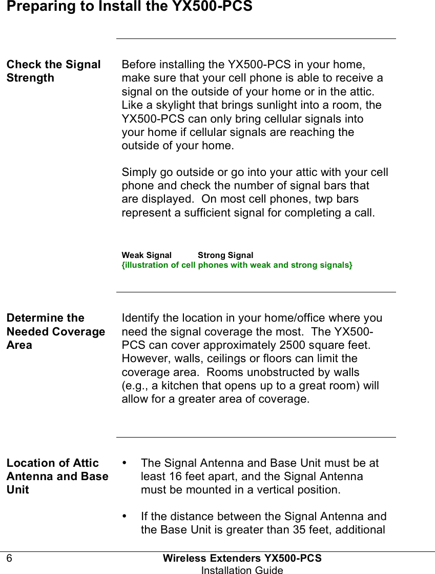
![Wireless Extenders YX500-PCS 7 Installation Guide coaxial cable will be required. For the best performance, The cable length should not exceed 60 feet. Power Requirements The Base Unit can be plugged into a standard 2-prong 110 VAC receptacle using the supplied power supply. Warning: The YX500-PCS base unit should only be used with the supplied power cable. Attempts to use other power cables will void the warranty. Installation Tools The following tools are required to install the YX500-PCS: • Nn-size wrench • Nn-size [Philips-head] screwdriver • Standard drill with nn” bit (optional) • PCS Cell phone operating at1900 MHz • Multi-meter for testing electrical continuity and AC line voltage (for troubleshooting only) Installing the YX500-PCS Installing the Signal Antenna Once you have confirmed that you have a cellular signal either outside your home or inside your attic, you are ready to install the Signal Antenna.](https://usermanual.wiki/zBoost/YX500-PCS/User-Guide-499328-Page-11.png)