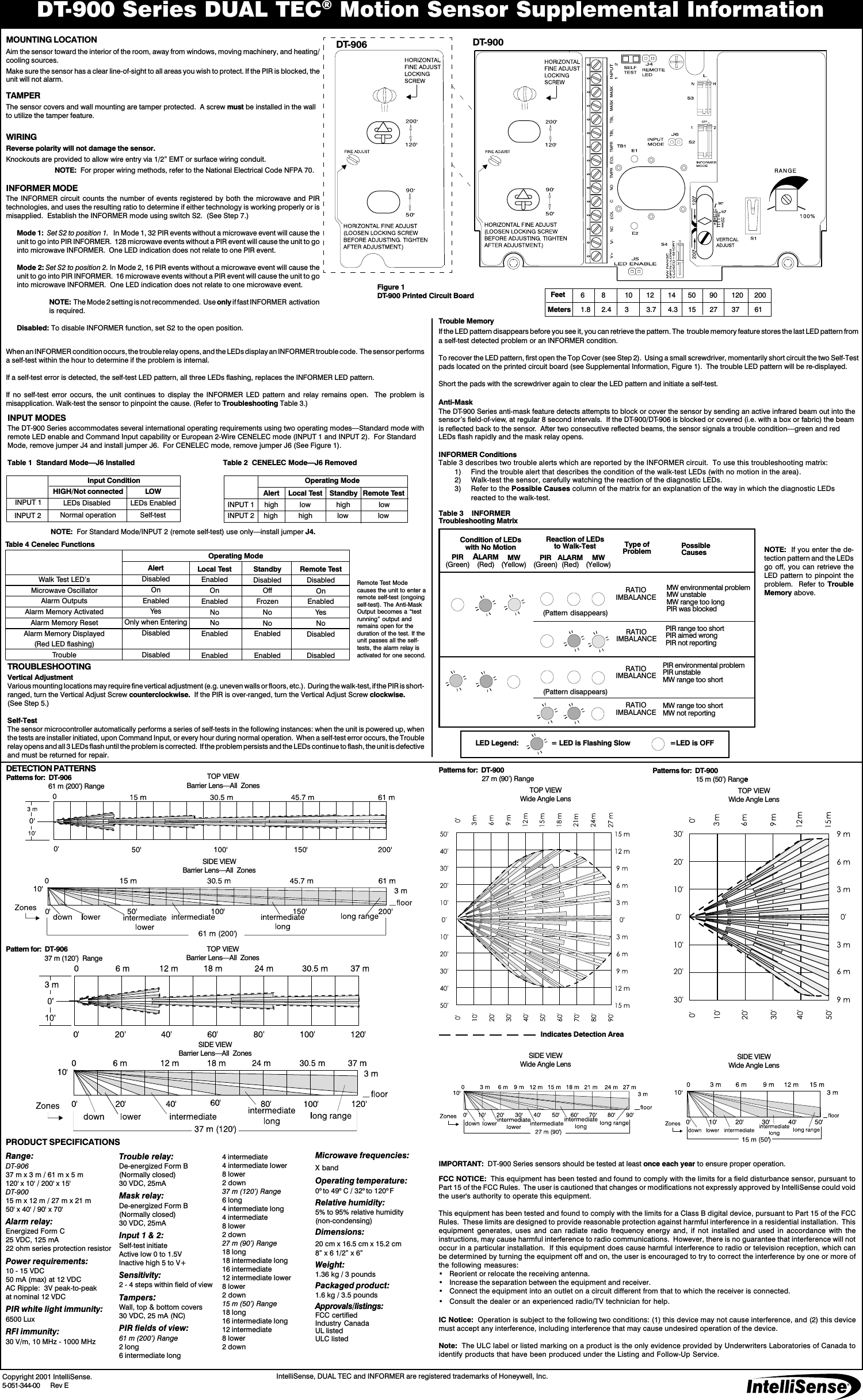
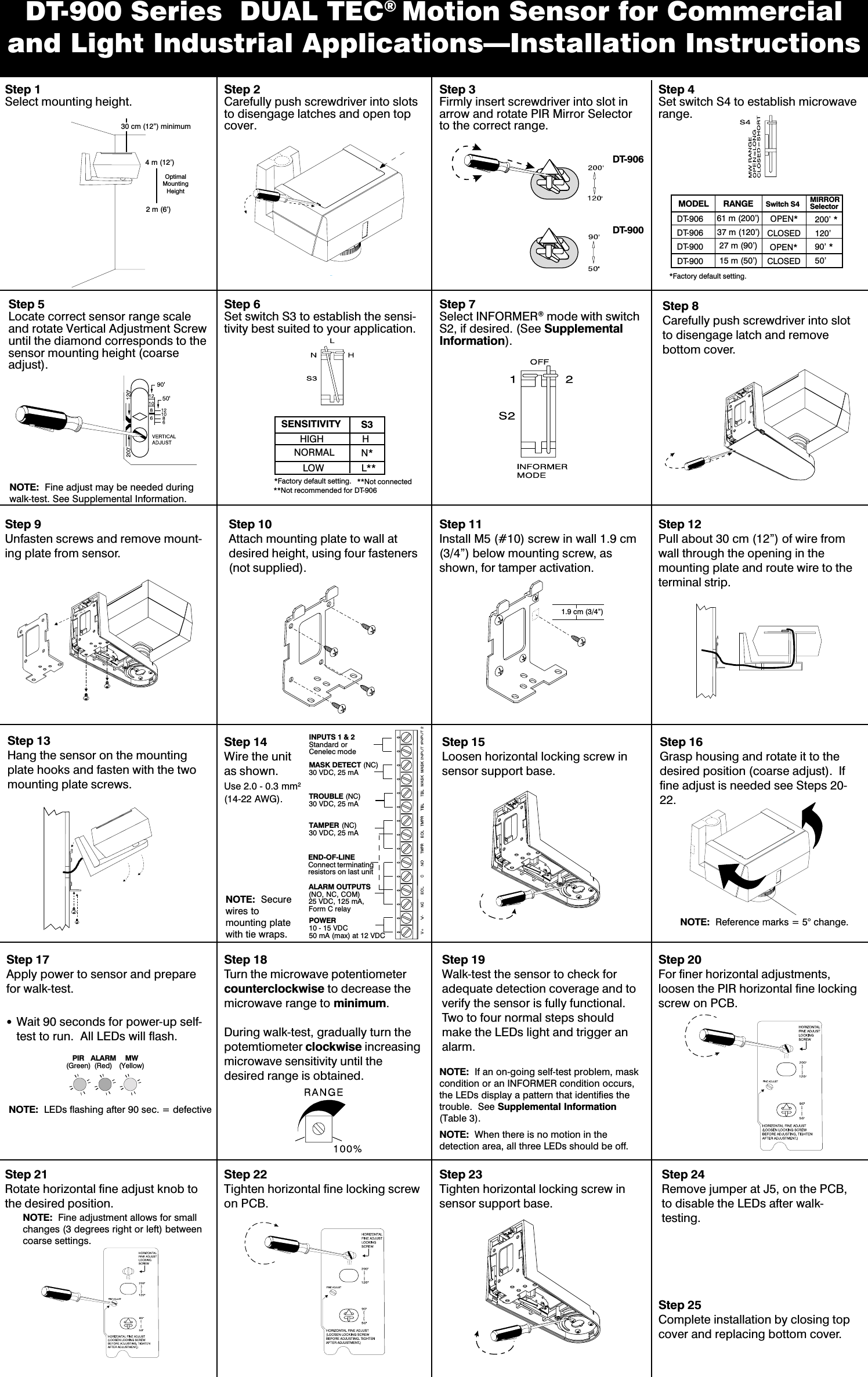
Ademco 0600906 Microwave/PIR motion sensor User Manual 505134401E

Honeywell International Inc. Microwave/PIR motion sensor 505134401E

Contents

User manual 1 of 2

DT-900 Series DUAL TEC® Motion Sensor Supplemental InformationINPUT MODESThe DT-900 Series accommodates several international operating requirements using two operating modesStandard mode withremote LED enable and Command Input capability or European 2-Wire CENELEC mode (INPUT 1 and INPUT 2).  For StandardMode, remove jumper J4 and install jumper J6.  For CENELEC mode, remove jumper J6 (See Figure 1).Table 1  Standard ModeJ6 Installed Table 2  CENELEC ModeJ6 RemovedNOTE:  For Standard Mode/INPUT 2 (remote self-test) use onlyinstall jumper J4.TROUBLESHOOTINGVertical AdjustmentVarious mounting locations may require fine vertical adjustment (e.g. uneven walls or floors, etc.).  During the walk-test, if the PIR is short-ranged, turn the Vertical Adjust Screw counterclockwise.  If the PIR is over-ranged, turn the Vertical Adjust Screw clockwise.(See Step 5.)Self-TestThe sensor microcontroller automatically performs a series of self-tests in the following instances: when the unit is powered up, whenthe tests are installer initiated, upon Command Input, or every hour during normal operation.  When a self-test error occurs, the Troublerelay opens and all 3 LEDs flash until the problem is corrected.  If the problem persists and the LEDs continue to flash, the unit is defectiveand must be returned for repair.MOUNTING LOCATIONAim the sensor toward the interior of the room, away from windows, moving machinery, and heating/cooling sources.Make sure the sensor has a clear line-of-sight to all areas you wish to protect. If the PIR is blocked, theunit will not alarm.TAMPERThe sensor covers and wall mounting are tamper protected.  A screw must be installed in the wallto utilize the tamper feature.WIRINGReverse polarity will not damage the sensor.Knockouts are provided to allow wire entry via 1/2 EMT or surface wiring conduit.NOTE:  For proper wiring methods, refer to the National Electrical Code NFPA 70.INFORMER MODEThe INFORMER circuit counts the number of events registered by both the microwave and PIRtechnologies, and uses the resulting ratio to determine if either technology is working properly or ismisapplied.  Establish the INFORMER mode using switch S2.  (See Step 7.)Mode 1:  Set S2 to position 1.   In Mode 1, 32 PIR events without a microwave event will cause theunit to go into PIR INFORMER.  128 microwave events without a PIR event will cause the unit to gointo microwave INFORMER.  One LED indication does not relate to one PIR event.Mode 2: Set S2 to position 2. In Mode 2, 16 PIR events without a microwave event will cause theunit to go into PIR INFORMER.  16 microwave events without a PIR event will cause the unit to gointo microwave INFORMER.  One LED indication does not relate to one microwave event.NOTE:  The Mode 2 setting is not recommended.  Use only if fast INFORMER  activationis required.Disabled: To disable INFORMER function, set S2 to the open position.NOTE:  If you enter the de-tection pattern and the LEDsgo off, you can retrieve theLED pattern to pinpoint theproblem.  Refer to TroubleMemory above.Table 3    INFORMERTroubleshooting Matrix  IntelliSense, DUAL TEC and INFORMER are registered trademarks of Honeywell, Inc.PRODUCT SPECIFICATIONSRange:DT-90637 m x 3 m / 61 m x 5 m120' x 10' / 200' x 15'DT-90015 m x 12 m / 27 m x 21 m50' x 40' / 90' x 70'Alarm relay:Energized Form C25 VDC, 125 mA22 ohm series protection resistorPower requirements:10 - 15 VDC50 mA (max) at 12 VDCAC Ripple:  3V peak-to-peakat nominal 12 VDCPIR white light immunity:6500 LuxRFI immunity:30 V/m, 10 MHz - 1000 MHzIMPORTANT:  DT-900 Series sensors should be tested at least once each year to ensure proper operation.DETECTION PATTERNSCopyright 2001 IntelliSense.5-051-344-00    Rev EINPUT 1Alert Local Test Standby Remote TestINPUT 2 high lowhigh low highPattern for:  DT-906  37 m (120)  RangePatterns for:  DT-906 61 m (200) RangeTOP VIEWBarrier LensAll  ZonesSIDE VIEWBarrier LensAll  ZonesTOP VIEWBarrier LensAll  ZonesSIDE VIEWBarrier LensAll  ZonesDT-900DT-906MW environmental problemMW unstableMW range too longPIR was blocked(Pattern disappears)(Pattern disappears)Reaction of LEDsto Walk-TestCondition of LEDswith No MotionMW(Yellow)ALARM(Red)PIR(Green) PIR(Green) MW(Yellow)ALARM(Red)RATIOIMBALANCERATIOIMBALANCEType ofProblemRATIOIMBALANCERATIOIMBALANCEPIR environmental problemPIR unstableMW range too shortPossibleCausesPIR range too shortPIR aimed wrongPIR not reportingMW range too shortMW not reportingTrouble relay:De-energized Form B(Normally closed)30 VDC, 25mAMask relay:De-energized Form B(Normally closed)30 VDC, 25mAInput 1 & 2:Self-test initiateActive low 0 to 1.5VInactive high 5 to V+Sensitivity:2 - 4 steps within field of viewTampers:Wall, top & bottom covers30 VDC, 25 mA (NC)PIR fields of view:61 m (200) Range2 long6 intermediate long4 intermediate4 intermediate lower8 lower2 down37 m (120) Range6 long4 intermediate long4 intermediate8 lower2 down27 m (90) Range18 long18 intermediate long16 intermediate12 intermediate lower8 lower2 down15 m (50) Range18 long16 intermediate long12 intermediate8 lower2 downMicrowave frequencies:X bandOperating temperature:0o to 49o C / 32o to 120o FRelative humidity:5% to 95% relative humidity(non-condensing)Dimensions:20 cm x 16.5 cm x 15.2 cm8 x 6 1/2 x 6Weight:1.36 kg / 3 poundsPackaged product:1.6 kg / 3.5 poundsApprovals/listings:FCC certifiedIndustry CanadaUL listedULC listedInput ConditionINPUT 1HIGH/Not connected LOWNormal operation Self-testLEDs Disabled LEDs EnabledlowOperating ModehighlowINPUT 2Trouble MemoryIf the LED pattern disappears before you see it, you can retrieve the pattern. The  trouble memory feature stores the last LED pattern froma self-test detected problem or an INFORMER condition.To recover the LED pattern, first open the Top Cover (see Step 2).  Using a small screwdriver, momentarily short circuit the two Self-Testpads located on the printed circuit board (see Supplemental Information, Figure 1).  The trouble LED pattern will be re-displayed.Short the pads with the screwdriver again to clear the LED pattern and initiate a self-test.Anti-MaskThe DT-900 Series anti-mask feature detects attempts to block or cover the sensor by sending an active infrared beam out into thesensors field-of-view, at regular 8 second intervals.  If the DT-900/DT-906 is blocked or covered (i.e. with a box or fabric) the beamis reflected back to the sensor.  After two consecutive reflected beams, the sensor signals a trouble conditiongreen and redLEDs flash rapidly and the mask relay opens.INFORMER ConditionsTable 3 describes two trouble alerts which are reported by the INFORMER circuit.  To use this troubleshooting matrix:1) Find the trouble alert that describes the condition of the walk-test LEDs (with no motion in the area).2) Walk-test the sensor, carefully watching the reaction of the diagnostic LEDs.3) Refer to the Possible Causes column of the matrix for an explanation of the way in which the diagnostic LEDsreacted to the walk-test.SIDE VIEWWide Angle LensPatterns for:  DT-90015 m (50) RangeTOP VIEWWide Angle LensPatterns for:  DT-90027 m (90) RangeTOP VIEWWide Angle LensSIDE VIEWWide Angle Lens6 8 10 12 14 50 90 120 2001.8 2.4 3 3.7 4.3 15 27 37 61FeetMetersFigure 1DT-900 Printed Circuit BoardLED Legend: = LED is Flashing Slow            =LED is OFFFCC NOTICE:  This equipment has been tested and found to comply with the limits for a field disturbance sensor, pursuant toPart 15 of the FCC Rules.  The user is cautioned that changes or modifications not expressly approved by IntelliSense could voidthe user's authority to operate this equipment.This equipment has been tested and found to comply with the limits for a Class B digital device, pursuant to Part 15 of the FCCRules.  These limits are designed to provide reasonable protection against harmful interference in a residential installation.  Thisequipment generates, uses  and  can  radiate  radio  frequency  energy  and,  if not installed  and  used  in  accordance  with  theinstructions, may cause harmful interference to radio communications.  However, there is no guarantee that interference will notoccur in a particular installation.  If this equipment does cause harmful interference to radio or television reception, which canbe determined by turning the equipment off and on, the user is encouraged to try to correct the interference by one or more ofthe following measures: Reorient or relocate the receiving antenna. Increase the separation between the equipment and receiver. Connect the equipment into an outlet on a circuit different from that to which the receiver is connected. Consult the dealer or an experienced radio/TV technician for help.IC Notice:  Operation is subject to the following two conditions: (1) this device may not cause interference, and (2) this devicemust accept any interference, including interference that may cause undesired operation of the device.Note:  The ULC label or listed marking on a product is the only evidence provided by Underwriters Laboratories of Canada toidentify products that have been produced under the Listing and Follow-Up Service.Indicates Detection AreaWhen an INFORMER condition occurs, the trouble relay opens, and the LEDs display an INFORMER trouble code.  The sensor performsa self-test within the hour to determine if the problem is internal.If a self-test error is detected, the self-test LED pattern, all three LEDs flashing, replaces the INFORMER LED pattern.If  no  self-test  error  occurs,  the  unit  continues  to  display  the  INFORMER  LED  pattern  and  relay  remains  open.    The  problem  ismisapplication. Walk-test the sensor to pinpoint the cause. (Refer to Troubleshooting Table 3.)Walk Test LEDsMicrowave OscillatorAlarm OutputsAlarm Memory ActivatedAlarm Memory ResetAlarm Memory Displayed(Red LED flashing)TroubleAlertDisabledOnEnabledYesOnly when EnteringDisabledDisabledLocal TestEnabledOnEnabledNoNoEnabledEnabledStandbyDisabledOffFrozenNoNoEnabledEnabledRemote TestDisabledOnEnabledYesNoDisabledDisabledTable 4 Cenelec FunctionsOperating ModeRemote Test Modecauses the unit to enter aremote self-test (ongoingself-test). The Anti-MaskOutput becomes a testrunning output andremains open for theduration of the test. If theunit passes all the self-tests, the alarm relay isactivated for one second.
DT-900 Series  DUAL TEC® Motion Sensor for Commercialand Light Industrial ApplicationsInstallation InstructionsStep 1Select mounting height. Step 2Carefully push screwdriver into slotsto disengage latches and open topcover.Step 3Firmly insert screwdriver into slot inarrow and rotate PIR Mirror Selectorto the correct range.Step 5Locate correct sensor range scaleand rotate Vertical Adjustment Screwuntil the diamond corresponds to thesensor mounting height (coarseadjust).Step 6Set switch S3 to establish the sensi-tivity best suited to your application.Step 7Select INFORMER® mode with switchS2, if desired. (See SupplementalInformation).SENSITIVITYHIGHLOWHN*L**S3NORMAL*Factory default setting. **Not connectedStep 8Carefully push screwdriver into slotto disengage latch and removebottom cover.Step 9Unfasten screws and remove mount-ing plate from sensor.Step 10Attach mounting plate to wall atdesired height, using four fasteners(not supplied).Step 11Install M5 (#10) screw in wall 1.9 cm(3/4) below mounting screw, asshown, for tamper activation.Step 12Pull about 30 cm (12) of wire fromwall through the opening in themounting plate and route wire to theterminal strip.Step 13Hang the sensor on the mountingplate hooks and fasten with the twomounting plate screws.Step 14Wire the unitas shown.Use 2.0 - 0.3 mm2(14-22 AWG).NOTE:  Securewires tomounting platewith tie wraps.Step 15Loosen horizontal locking screw insensor support base.Step 16Grasp housing and rotate it to thedesired position (coarse adjust).  Iffine adjust is needed see Steps 20-22.NOTE:  Reference marks = 5° change.Step 17Apply power to sensor and preparefor walk-test.1.9 cm (3/4)Step 20For finer horizontal adjustments,loosen the PIR horizontal fine lockingscrew on PCB.Step 22Tighten horizontal fine locking screwon PCB.NOTE:  Fine adjustment allows for smallchanges (3 degrees right or left) betweencoarse settings.Step 21Rotate horizontal fine adjust knob tothe desired position.30 cm (12) minimumINPUTS 1 & 2Standard orCenelec modeTROUBLE (NC)30 VDC, 25 mATAMPER (NC)30 VDC, 25 mAALARM OUTPUTS(NO, NC, COM)25 VDC, 125 mA,Form C relayEND-OF-LINEConnect terminatingresistors on last unitPOWER10 - 15 VDC50 mA (max) at 12 VDCMASK DETECT (NC)30 VDC, 25 mADT-900DT-906MODEL RANGE Switch S4 MIRRORSelector*Factory default setting.Step 4Set switch S4 to establish microwaverange.Step 23Tighten horizontal locking screw insensor support base.Step 24Remove jumper at J5, on the PCB,to disable the LEDs after walk-testing.Step 25Complete installation by closing topcover and replacing bottom cover.Wait 90 seconds for power-up self-test to run.  All LEDs will flash.. NOTE:  LEDs flashing after 90 sec. = defectivePIR(Green) MW(Yellow)ALARM(Red)NOTE:  Fine adjust may be needed duringwalk-test. See Supplemental Information.2 m (6)4 m (12)DT-900 15 m (50) CLOSED 50DT-906 61 m (200) OPEN* 200 *DT-906 37 m (120) CLOSED 120DT-900 27 m (90) OPEN* 90 *Step 19Walk-test the sensor to check foradequate detection coverage and toverify the sensor is fully functional.Two to four normal steps shouldmake the LEDs light and trigger analarm.NOTE:  When there is no motion in thedetection area, all three LEDs should be off.NOTE:  If an on-going self-test problem, maskcondition or an INFORMER condition occurs,the LEDs display a pattern that identifies thetrouble.  See Supplemental Information(Table 3).Step 18Turn the microwave potentiometercounterclockwise to decrease themicrowave range to minimum.During walk-test, gradually turn thepotemtiometer clockwise increasingmicrowave sensitivity until thedesired range is obtained.**Not recommended for DT-906OptimalMountingHeight

Navigation menu