Ademco 0600906 Microwave/PIR motion sensor User Manual 505134401E
Honeywell International Inc. Microwave/PIR motion sensor 505134401E
Ademco >
Contents
- 1. User manual 1 of 2
- 2. User manual 2 of 2
User manual 1 of 2
DT-900 Series DUAL TEC® Motion Sensor Supplemental Information
INPUT MODES
The DT-900 Series accommodates several international operating requirements using two operating modesStandard mode with
remote LED enable and Command Input capability or European 2-Wire CENELEC mode (INPUT 1 and INPUT 2). For Standard
Mode, remove jumper J4 and install jumper J6. For CENELEC mode, remove jumper J6 (See Figure 1).
Table 1 Standard ModeJ6 Installed Table 2 CENELEC ModeJ6 Removed
NOTE: For Standard Mode/INPUT 2 (remote self-test) use onlyinstall jumper J4.
TROUBLESHOOTING
Vertical Adjustment
Various mounting locations may require fine vertical adjustment (e.g. uneven walls or floors, etc.). During the walk-test, if the PIR is short-
ranged, turn the Vertical Adjust Screw counterclockwise. If the PIR is over-ranged, turn the Vertical Adjust Screw clockwise.
(See Step 5.)
Self-Test
The sensor microcontroller automatically performs a series of self-tests in the following instances: when the unit is powered up, when
the tests are installer initiated, upon Command Input, or every hour during normal operation. When a self-test error occurs, the Trouble
relay opens and all 3 LEDs flash until the problem is corrected. If the problem persists and the LEDs continue to flash, the unit is defective
and must be returned for repair.
MOUNTING LOCATION
Aim the sensor toward the interior of the room, away from windows, moving machinery, and heating/
cooling sources.
Make sure the sensor has a clear line-of-sight to all areas you wish to protect. If the PIR is blocked, the
unit will not alarm.
TAMPER
The sensor covers and wall mounting are tamper protected. A screw must be installed in the wall
to utilize the tamper feature.
WIRING
Reverse polarity will not damage the sensor.
Knockouts are provided to allow wire entry via 1/2 EMT or surface wiring conduit.
NOTE: For proper wiring methods, refer to the National Electrical Code NFPA 70.
INFORMER MODE
The INFORMER circuit counts the number of events registered by both the microwave and PIR
technologies, and uses the resulting ratio to determine if either technology is working properly or is
misapplied. Establish the INFORMER mode using switch S2. (See Step 7.)
Mode 1: Set S2 to position 1. In Mode 1, 32 PIR events without a microwave event will cause the
unit to go into PIR INFORMER. 128 microwave events without a PIR event will cause the unit to go
into microwave INFORMER. One LED indication does not relate to one PIR event.
Mode 2: Set S2 to position 2. In Mode 2, 16 PIR events without a microwave event will cause the
unit to go into PIR INFORMER. 16 microwave events without a PIR event will cause the unit to go
into microwave INFORMER. One LED indication does not relate to one microwave event.
NOTE: The Mode 2 setting is not recommended. Use only if fast INFORMER activation
is required.
Disabled: To disable INFORMER function, set S2 to the open position.
NOTE: If you enter the de-
tection pattern and the LEDs
go off, you can retrieve the
LED pattern to pinpoint the
problem. Refer to Trouble
Memory above.
Table 3 INFORMER
Troubleshooting Matrix
IntelliSense, DUAL TEC and INFORMER are registered trademarks of Honeywell, Inc.
PRODUCT SPECIFICATIONS
Range:
DT-906
37 m x 3 m / 61 m x 5 m
120' x 10' / 200' x 15'
DT-900
15 m x 12 m / 27 m x 21 m
50' x 40' / 90' x 70'
Alarm relay:
Energized Form C
25 VDC, 125 mA
22 ohm series protection resistor
Power requirements:
10 - 15 VDC
50 mA (max) at 12 VDC
AC Ripple: 3V peak-to-peak
at nominal 12 VDC
PIR white light immunity:
6500 Lux
RFI immunity:
30 V/m, 10 MHz - 1000 MHz
IMPORTANT: DT-900 Series sensors should be tested at least once each year to ensure proper operation.
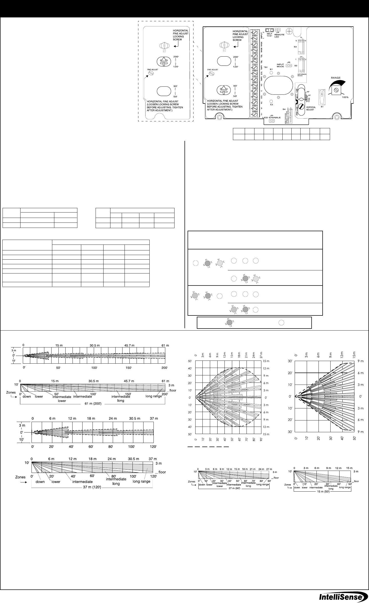
DETECTION PATTERNS
Copyright 2001 IntelliSense.
5-051-344-00 Rev E
INPUT 1
Alert Local Test Standby Remote Test
INPUT 2 high low
high low high
Pattern for: DT-906
37 m (120) Range
Patterns for: DT-906
61 m (200) Range
TOP VIEW
Barrier LensAll Zones
SIDE VIEW
Barrier LensAll Zones
TOP VIEW
Barrier LensAll Zones
SIDE VIEW
Barrier LensAll Zones
DT-900
DT-906
MW environmental problem
MW unstable
MW range too long
PIR was blocked
(Pattern disappears)
(Pattern disappears)
Reaction of LEDs
to Walk-Test
Condition of LEDs
with No Motion
MW
(Yellow)
ALARM
(Red)
PIR
(Green) PIR
(Green) MW
(Yellow)
ALARM
(Red)
RATIO
IMBALANCE
RATIO
IMBALANCE
Type of
Problem
RATIO
IMBALANCE
RATIO
IMBALANCE
PIR environmental problem
PIR unstable
MW range too short
Possible
Causes
PIR range too short
PIR aimed wrong
PIR not reporting
MW range too short
MW not reporting
Trouble relay:
De-energized Form B
(Normally closed)
30 VDC, 25mA
Mask relay:
De-energized Form B
(Normally closed)
30 VDC, 25mA
Input 1 & 2:
Self-test initiate
Active low 0 to 1.5V
Inactive high 5 to V+
Sensitivity:
2 - 4 steps within field of view
Tampers:
Wall, top & bottom covers
30 VDC, 25 mA (NC)
PIR fields of view:
61 m (200) Range
2 long
6 intermediate long
4 intermediate
4 intermediate lower
8 lower
2 down
37 m (120) Range
6 long
4 intermediate long
4 intermediate
8 lower
2 down
27 m (90) Range
18 long
18 intermediate long
16 intermediate
12 intermediate lower
8 lower
2 down
15 m (50) Range
18 long
16 intermediate long
12 intermediate
8 lower
2 down
Microwave frequencies:
X band
Operating temperature:
0o to 49o C / 32o to 120o F
Relative humidity:
5% to 95% relative humidity
(non-condensing)
Dimensions:
20 cm x 16.5 cm x 15.2 cm
8 x 6 1/2 x 6
Weight:
1.36 kg / 3 pounds
Packaged product:
1.6 kg / 3.5 pounds
Approvals/listings:
FCC certified
Industry Canada
UL listed
ULC listed
Input Condition
INPUT 1
HIGH/Not connected LOW
Normal operation Self-test
LEDs Disabled LEDs Enabled
low
Operating Mode
high
low
INPUT 2
Trouble Memory
If the LED pattern disappears before you see it, you can retrieve the pattern. The trouble memory feature stores the last LED pattern from
a self-test detected problem or an INFORMER condition.
To recover the LED pattern, first open the Top Cover (see Step 2). Using a small screwdriver, momentarily short circuit the two Self-Test
pads located on the printed circuit board (see Supplemental Information, Figure 1). The trouble LED pattern will be re-displayed.
Short the pads with the screwdriver again to clear the LED pattern and initiate a self-test.
Anti-Mask
The DT-900 Series anti-mask feature detects attempts to block or cover the sensor by sending an active infrared beam out into the
sensors field-of-view, at regular 8 second intervals. If the DT-900/DT-906 is blocked or covered (i.e. with a box or fabric) the beam
is reflected back to the sensor. After two consecutive reflected beams, the sensor signals a trouble conditiongreen and red
LEDs flash rapidly and the mask relay opens.
INFORMER Conditions
Table 3 describes two trouble alerts which are reported by the INFORMER circuit. To use this troubleshooting matrix:
1) Find the trouble alert that describes the condition of the walk-test LEDs (with no motion in the area).
2) Walk-test the sensor, carefully watching the reaction of the diagnostic LEDs.
3) Refer to the Possible Causes column of the matrix for an explanation of the way in which the diagnostic LEDs
reacted to the walk-test.
SIDE VIEW
Wide Angle Lens
Patterns for: DT-900
15 m (50) Range
TOP VIEW
Wide Angle Lens
Patterns for: DT-900
27 m (90) Range
TOP VIEW
Wide Angle Lens
SIDE VIEW
Wide Angle Lens
6 8 10 12 14 50 90 120 200
1.8 2.4 3 3.7 4.3 15 27 37 61
Feet
Meters
Figure 1
DT-900 Printed Circuit Board
LED Legend: = LED is Flashing Slow =LED is OFF
FCC NOTICE: This equipment has been tested and found to comply with the limits for a field disturbance sensor, pursuant to
Part 15 of the FCC Rules. The user is cautioned that changes or modifications not expressly approved by IntelliSense could void
the user's authority to operate this equipment.
This equipment has been tested and found to comply with the limits for a Class B digital device, pursuant to Part 15 of the FCC
Rules. These limits are designed to provide reasonable protection against harmful interference in a residential installation. This
equipment generates, uses and can radiate radio frequency energy and, if not installed and used in accordance with the
instructions, may cause harmful interference to radio communications. However, there is no guarantee that interference will not
occur in a particular installation. If this equipment does cause harmful interference to radio or television reception, which can
be determined by turning the equipment off and on, the user is encouraged to try to correct the interference by one or more of
the following measures:
Reorient or relocate the receiving antenna.
Increase the separation between the equipment and receiver.
Connect the equipment into an outlet on a circuit different from that to which the receiver is connected.
Consult the dealer or an experienced radio/TV technician for help.
IC Notice: Operation is subject to the following two conditions: (1) this device may not cause interference, and (2) this device
must accept any interference, including interference that may cause undesired operation of the device.
Note: The ULC label or listed marking on a product is the only evidence provided by Underwriters Laboratories of Canada to
identify products that have been produced under the Listing and Follow-Up Service.
Indicates Detection Area
When an INFORMER condition occurs, the trouble relay opens, and the LEDs display an INFORMER trouble code. The sensor performs
a self-test within the hour to determine if the problem is internal.
If a self-test error is detected, the self-test LED pattern, all three LEDs flashing, replaces the INFORMER LED pattern.
If no self-test error occurs, the unit continues to display the INFORMER LED pattern and relay remains open. The problem is
misapplication. Walk-test the sensor to pinpoint the cause. (Refer to Troubleshooting Table 3.)
Walk Test LEDs
Microwave Oscillator
Alarm Outputs
Alarm Memory Activated
Alarm Memory Reset
Alarm Memory Displayed
(Red LED flashing)
Trouble
Alert
Disabled
On
Enabled
Yes
Only when Entering
Disabled
Disabled
Local Test
Enabled
On
Enabled
No
No
Enabled
Enabled
Standby
Disabled
Off
Frozen
No
No
Enabled
Enabled
Remote Test
Disabled
On
Enabled
Yes
No
Disabled
Disabled
Table 4 Cenelec Functions
Operating Mode
Remote Test Mode
causes the unit to enter a
remote self-test (ongoing
self-test). The Anti-Mask
Output becomes a test
running output and
remains open for the
duration of the test. If the
unit passes all the self-
tests, the alarm relay is
activated for one second.
DT-900 Series DUAL TEC® Motion Sensor for Commercial
and Light Industrial ApplicationsInstallation Instructions
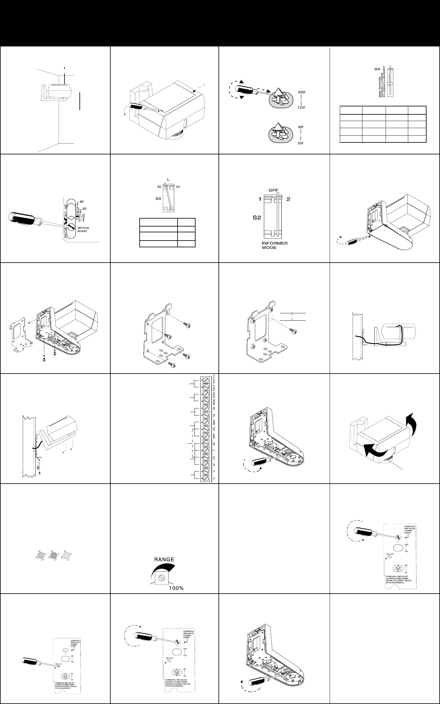
Step 1
Select mounting height. Step 2
Carefully push screwdriver into slots
to disengage latches and open top
cover.
Step 3
Firmly insert screwdriver into slot in
arrow and rotate PIR Mirror Selector
to the correct range.
Step 5
Locate correct sensor range scale
and rotate Vertical Adjustment Screw
until the diamond corresponds to the
sensor mounting height (coarse
adjust).
Step 6
Set switch S3 to establish the sensi-
tivity best suited to your application.
Step 7
Select INFORMER® mode with switch
S2, if desired. (See Supplemental
Information).
SENSITIVITY
HIGH
LOW
H
N*
L**
S3
NORMAL
*Factory default setting. **Not connected
Step 8
Carefully push screwdriver into slot
to disengage latch and remove
bottom cover.
Step 9
Unfasten screws and remove mount-
ing plate from sensor.
Step 10
Attach mounting plate to wall at
desired height, using four fasteners
(not supplied).
Step 11
Install M5 (#10) screw in wall 1.9 cm
(3/4) below mounting screw, as
shown, for tamper activation.
Step 12
Pull about 30 cm (12) of wire from
wall through the opening in the
mounting plate and route wire to the
terminal strip.
Step 13
Hang the sensor on the mounting
plate hooks and fasten with the two
mounting plate screws.
Step 14
Wire the unit
as shown.
Use 2.0 - 0.3 mm2
(14-22 AWG).
NOTE: Secure
wires to
mounting plate
with tie wraps.
Step 15
Loosen horizontal locking screw in
sensor support base.
Step 16
Grasp housing and rotate it to the
desired position (coarse adjust). If
fine adjust is needed see Steps 20-
22.
NOTE: Reference marks = 5° change.
Step 17
Apply power to sensor and prepare
for walk-test.
1.9 cm (3/4)
Step 20
For finer horizontal adjustments,
loosen the PIR horizontal fine locking
screw on PCB.
Step 22
Tighten horizontal fine locking screw
on PCB.
NOTE: Fine adjustment allows for small
changes (3 degrees right or left) between
coarse settings.
Step 21
Rotate horizontal fine adjust knob to
the desired position.
30 cm (12) minimum
INPUTS 1 & 2
Standard or
Cenelec mode
TROUBLE (NC)
30 VDC, 25 mA
TAMPER (NC)
30 VDC, 25 mA
ALARM OUTPUTS
(NO, NC, COM)
25 VDC, 125 mA,
Form C relay
END-OF-LINE
Connect terminating
resistors on last unit
POWER
10 - 15 VDC
50 mA (max) at 12 VDC
MASK DETECT (NC)
30 VDC, 25 mA
DT-900
DT-906
MODEL RANGE Switch S4 MIRROR
Selector
*Factory default setting.
Step 4
Set switch S4 to establish microwave
range.
Step 23
Tighten horizontal locking screw in
sensor support base.
Step 24
Remove jumper at J5, on the PCB,
to disable the LEDs after walk-
testing.
Step 25
Complete installation by closing top
cover and replacing bottom cover.
Wait 90 seconds for power-up self-
test to run. All LEDs will flash.
.
NOTE: LEDs flashing after 90 sec. = defective
PIR
(Green) MW
(Yellow)
ALARM
(Red)
NOTE: Fine adjust may be needed during
walk-test. See Supplemental Information.
2 m (6)
4 m (12)
DT-900 15 m (50) CLOSED 50
DT-906 61 m (200) OPEN* 200 *
DT-906 37 m (120) CLOSED 120
DT-900 27 m (90) OPEN* 90 *
Step 19
Walk-test the sensor to check for
adequate detection coverage and to
verify the sensor is fully functional.
Two to four normal steps should
make the LEDs light and trigger an
alarm.
NOTE: When there is no motion in the
detection area, all three LEDs should be off.
NOTE: If an on-going self-test problem, mask
condition or an INFORMER condition occurs,
the LEDs display a pattern that identifies the
trouble. See Supplemental Information
(Table 3).
Step 18
Turn the microwave potentiometer
counterclockwise to decrease the
microwave range to minimum.
During walk-test, gradually turn the
potemtiometer clockwise increasing
microwave sensitivity until the
desired range is obtained.
**Not recommended for DT-906
Optimal
Mounting
Height