Baron Services XDD-1000C C-BAND DOPPLER WEATHER RADAR User Manual TECHNICAL CHARACTERISTICS
Baron Services Inc C-BAND DOPPLER WEATHER RADAR TECHNICAL CHARACTERISTICS
Contents
- 1. Modulator Manual
- 2. Users Manual Part 1
- 3. Users Manual Part 2
- 4. Users Manual Part 3
- 5. S10 OPERATION AND MAINTENANCE MANUAL
- 6. S10 FAST TRAC MILLENIUM USERS GUIDE
- 7. S10 TECHNICAL MANUAL
- 8. S10 RECEIVER AND PROCESSOR USERS MANUAL PART 1
- 9. S10 RECEIVER AND PROCESSOR USERS MANUAL PART 2
- 10. S10 RECEIVER AND PROCESSOR USERS MANUAL PART 3
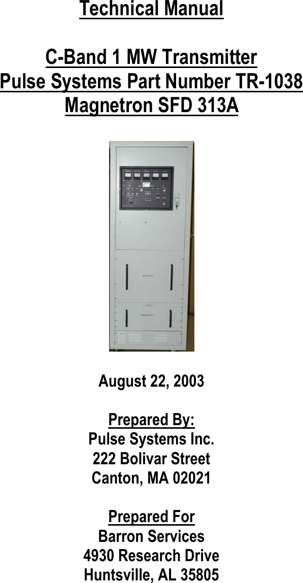
Modulator Manual