COSMED Srl K4B2R-USA TELEMETRY UNIT User Manual User man K4B2 en
COSMED Srl TELEMETRY UNIT User man K4B2 en
UserManual.wiki
>
COSMED Srl
>
K4B2R-USA User Manual
>
Users Manual I
Contents
1.
Users Manual I
2.
Users Manual II
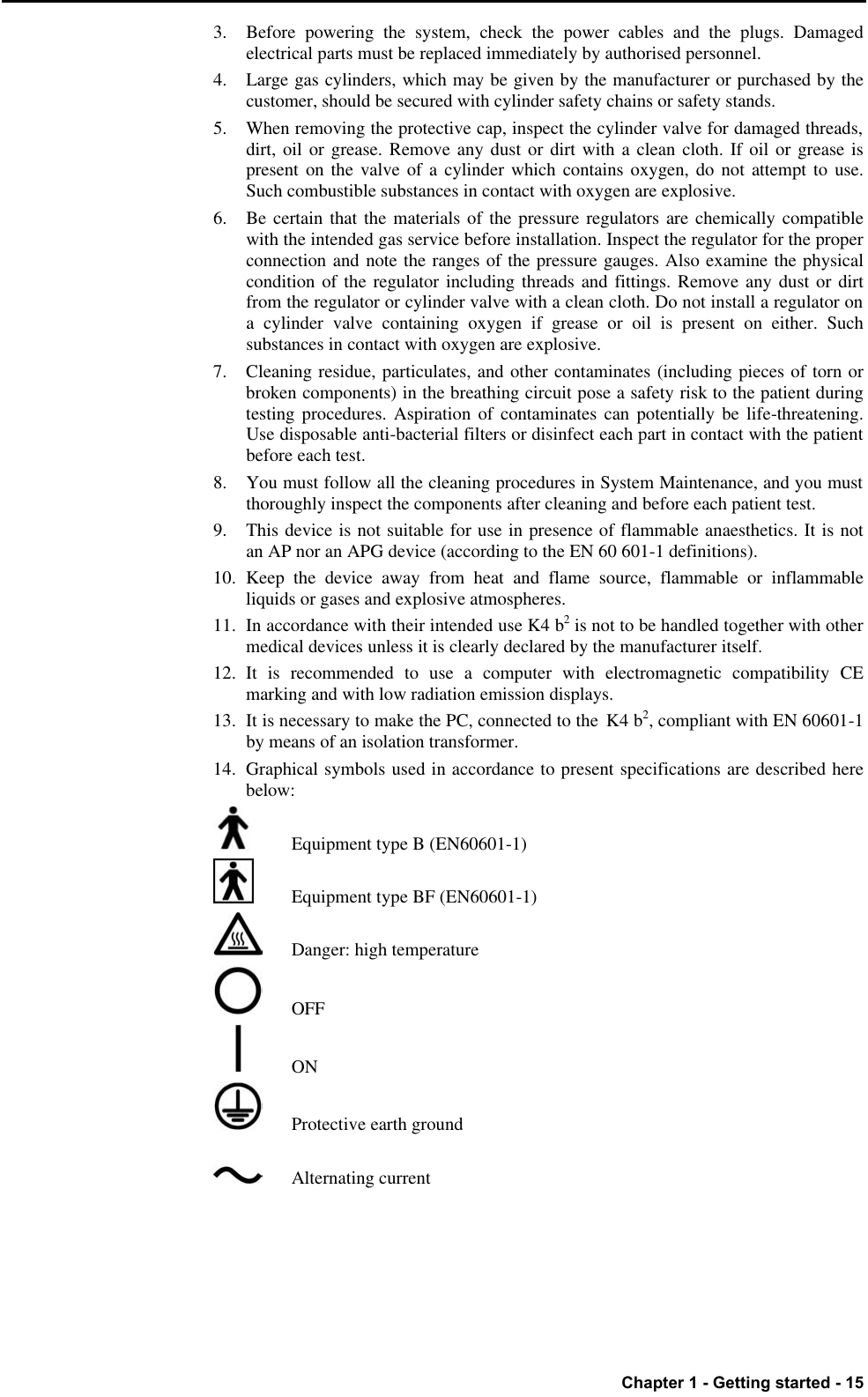
3.
Users Manual III
4.
Users Manual IV
Users Manual I
Navigation menu
Upload a User Manual
Namespaces
Wiki Guide
HTML
PDF
Info
Views
User Manual
Discussion / Help
Navigation


![Chapter 1 - Getting started - 17 Environmental condition of use COSMED units have been conceived for operating in medically utilised rooms without potential explosion hazards. The units should not be installed in vicinity of x-ray equipment, motors or transformers with high installed power rating since electric or magnetic interferences may falsify the result of measurements or make them impossible. Due to this the vicinity of power lines is to be avoided as well. Cosmed equipment are not AP not APG devices (according to EN 60601-1): they are not suitable for use in presence of flammable anaesthetic mixtures with air, oxygen or nitrogen protoxide. If not otherwise stated in the shipping documents, Cosmed equipment have been conceived for operating under normal environmental temperatures and conditions [IEC 601-1(1988)/EN 60 601-1 (1990)]. • Temperature range 10°C (50°F) and 40°C (104°F). • Relative humidity range 20% to 80% • Atmospheric Pressure range 700 to 1060 mBar • Avoid to use it in presence of noxious fumes or dusty environment and near heat sources. • Do not place near heat sources. • Cardiopulmonary resuscitation emergency equipment accessible. • Adequate floor space to assure access to the patient during exercise testing. • Adequate ventilation in the room.](https://usermanual.wiki/COSMED-Srl/K4B2R-USA.Users-Manual-I/User-Guide-569365-Page-17.png)