Code Systems PAN06 Car Alarm Receiver User Manual
Code Systems Inc Car Alarm Receiver
UserManual.wiki
>
Code Systems
>
PAN06 User Manual
User Manual
Navigation menu
Upload a User Manual
Namespaces
Wiki Guide
HTML
PDF
Info
Views
User Manual
Discussion / Help
Navigation
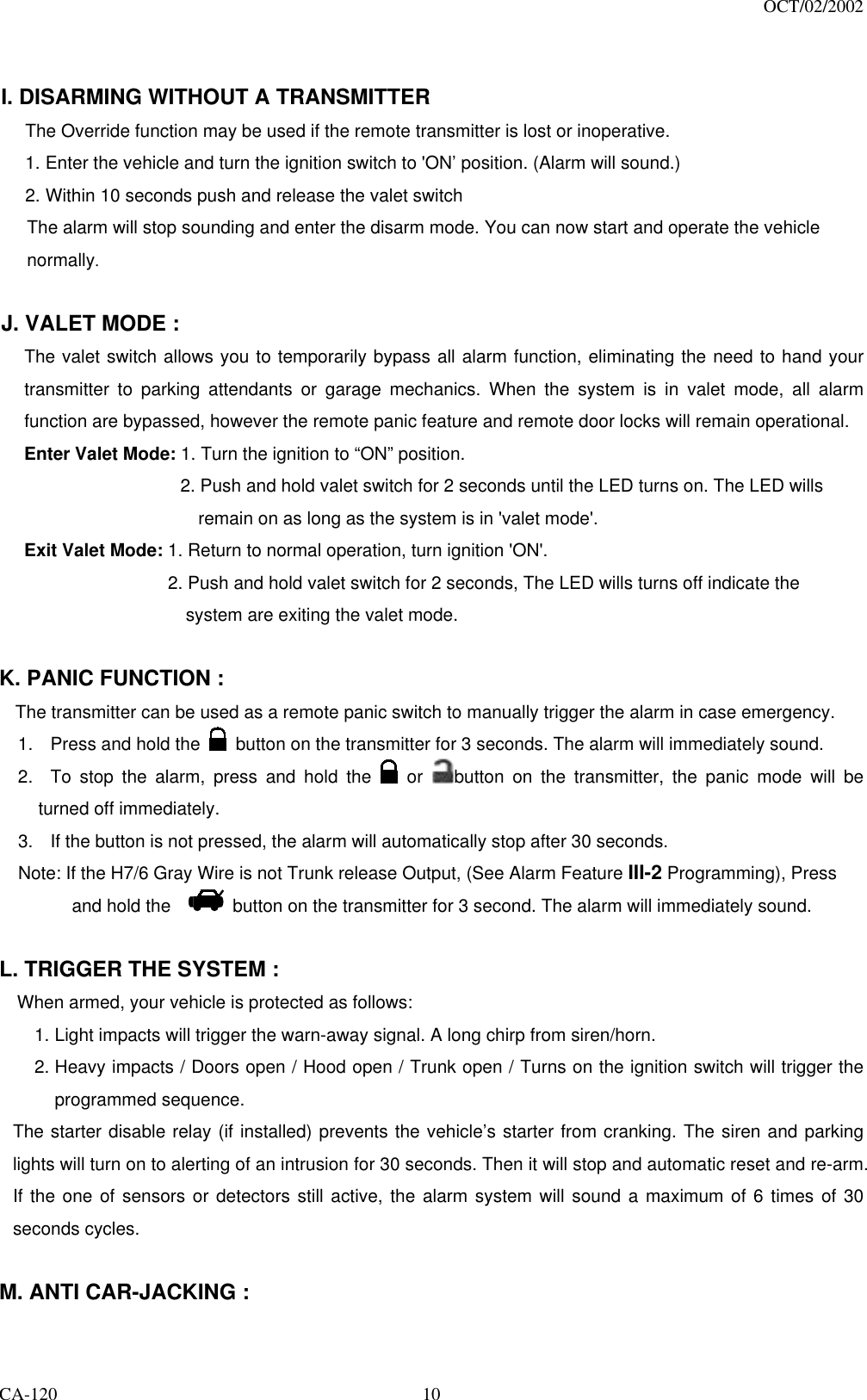
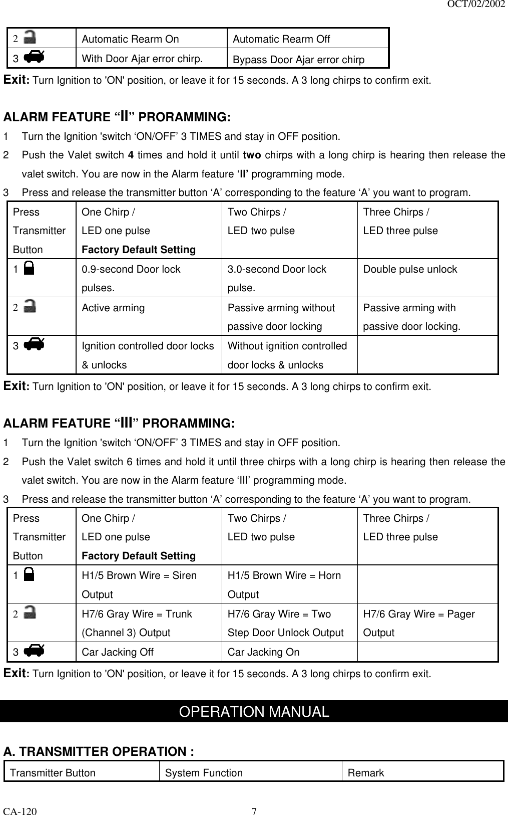
![OCT/02/2002 CA-120 6 H5: RF ANTENNA - BLACK THIN WIRE : The black thin wire on control module is the receiver antenna wire. Antenna placement is very important! Ensure that it is unwrapped and stretched out with the last 6" straight and keep it away from large metal objects or chassis for best reception. PROGRAMMING A. PROGRAMMING TRANSMITTER: Enter: 1. Turn the Ignition 'switch ‘OFF/ON’ 3 TIMES and stay in ON position. Within 15 seconds. 2. Push the Valet switch 3 times and hold it until a long chirp is hearing then release the valet switch. You are now in the Transmitter programming mode. Program: 1. Press button on one of the transmitter until the siren responds with a confirming chirp the first transmitter is now programmed. 2. Press button on the second transmitter until the siren responds with a confirming chirp, the second transmitter is now programmed. 3. Apply the same procedure to program 3rd and 4th. Exit: Turn Ignition to 'OFF' position, or leave it for 15 seconds. A 3 long chirps to confirm exit. Note: If more than 4 transmitters programmed, the system only kept the last 4 transmitters. B. ALARM FEATURES PROGRAMMING: ALARM FEATURE “I” PRORAMMING: 1. Turn the Ignition 'switch ‘ON/OFF’ 3 TIMES and stay in OFF position. 2. Push the Valet switch 2 times and hold it until one chirp with a long chirp is hearing then release the valet switch. You are now in the Alarm feature ‘I’ programming mode. 3. Press and release the transmitter button ‘A’ corresponding to the feature ‘A’ you want to change. a. The siren chirps and LED pause will indicate newly setting. b. The system would advance to [2] LED flash, [2] chirp. (The factory default settings is always [1] LED flash, [1] chirp.) 4 Depress the transmitter button ‘A’ again to change the feature again. Simple keep re-depressing the transmitter button ‘A’ again until the module advances to your desired setting. 5. Depress the transmitter button ‘B’ corresponding to the feature ‘B’ you want to program. Press Transmitter Button One Chirp / LED one pulse Factory Default Setting Two Chirps / LED two pulse 1 Chirps on Chirps off](https://usermanual.wiki/Code-Systems/PAN06/User-Guide-359712-Page-6.png)
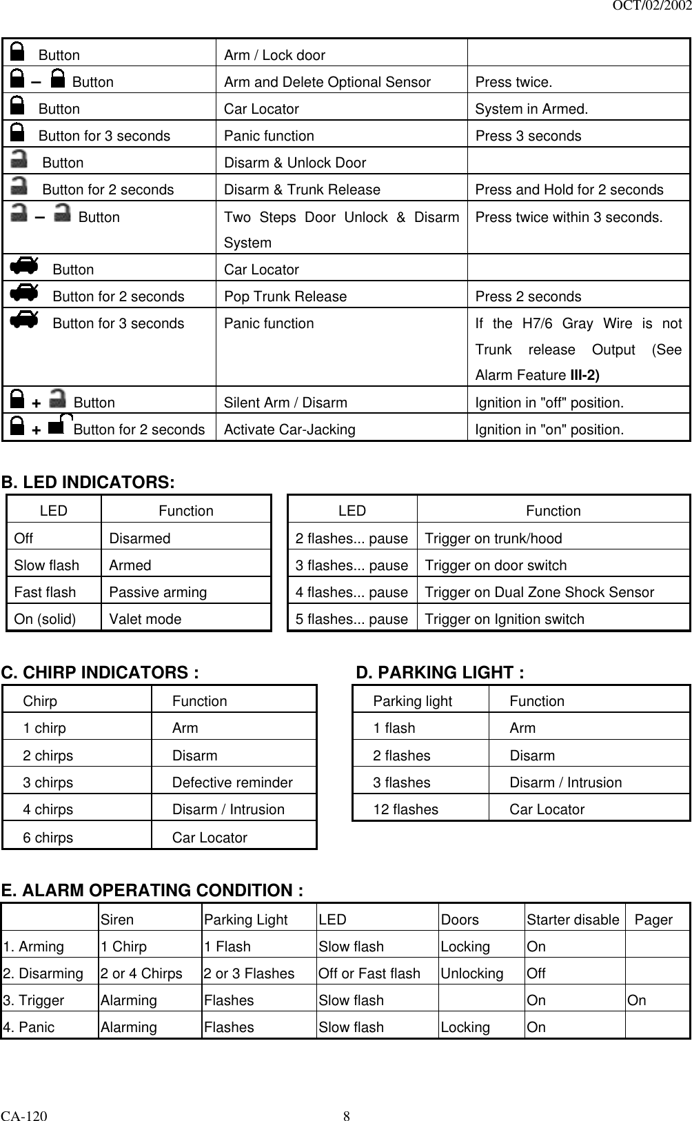
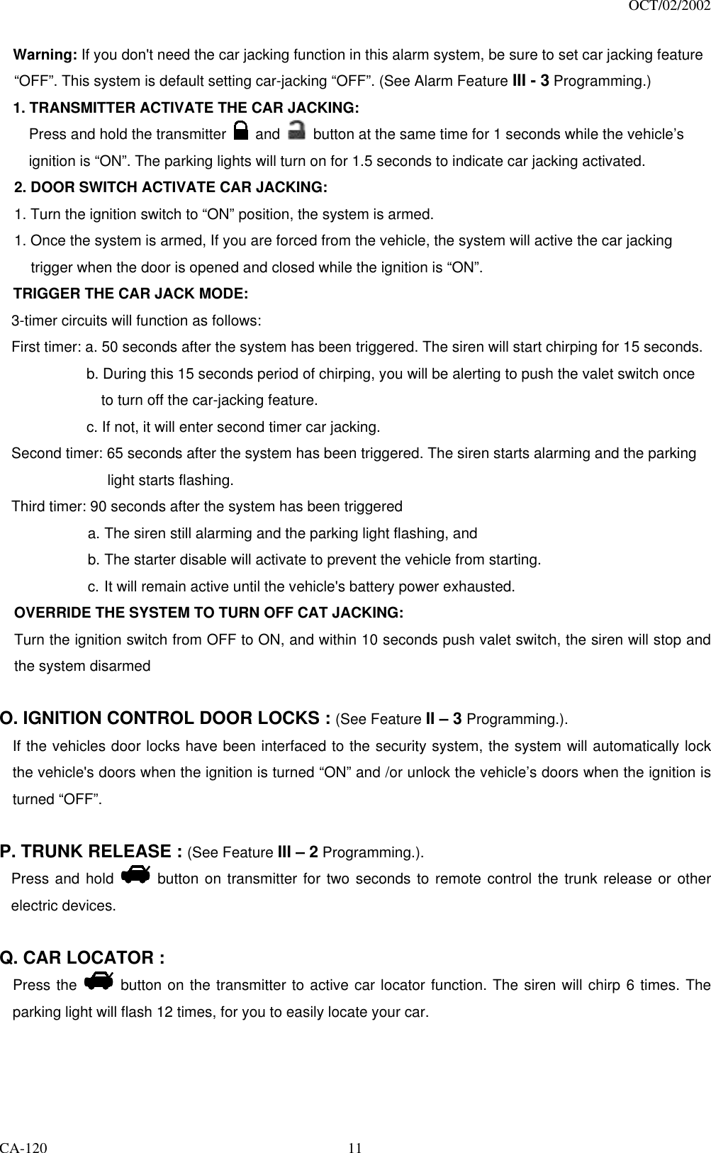
![OCT/02/2002 CA-120 9 F. ACTIVE ARMING – LOCK & ARM : 1. Press button on transmitter. 2. The siren will chirp once and parking light will flash once indicating that the system is now armed. The vehicle doors will lock upon arming when interfaced with the security system. Note: Defective sensor reminder: If the siren sounds 3 chirps, then you have left a door, trunk, or hood lid ajar. (See Feature “I - 3 Programming) SILENT ARMING / DISARMING: Press the + button together on the transmitter will arm or disarm your security system, No chirp sound will be heard, arm / disarm confirmation will be through the vehicles parking lights only. SHOCK SENSOR / OPTIONAL SENSOR BY-PASS: Press the button on the transmitter twice within 3 seconds will arm the security system, by-pass the shock sensor and the optional sensor connected to 4 pin plug. The system will chirp one additional time to confirm the sensor bypass mode was activated. The sensor bypass feature is programmed to activate for one arming cycle only. The security system will return to normal operation during the next arming cycle. G. PASSIVE ARMING : (See Feature “II - 2” Programming) Active arming / disarming is controlling your security system via the remote transmitter. This security system is equipped with an optional Passive Arming feature, which allows the security system to arm 30 seconds after the last door is closed. Operation is as follows. 1. Turn the ignition to the “OFF” position and exit the vehicle. 2. After all entrances are closed, the security system LED will flash fast for 30 seconds. If you reopen any door / hood / trunk, the security system LED will stop flashing. It will begin flashing again once the vehicle all entrances are closed. 3. After 30-second timer has elapsed, the security system will automatically “ARM”. The siren will chirp [1] time and the parking lights will flash [1] time. PASSIVE DOOR LOCKING: (See Feature “II - 2” Programming) The vehicle doors will automatically lock after passive arming cycle has been completed. H. ACTIVE DISARMING – UNLOCK & DISARM : 1. Press the button on the transmitter. 2. The siren will chirp twice and parking light will flash twice to indicating that the security system is now disarmed. The vehicle doors will unlock disarming when interfaced with the security system. TAMPER DISARMING: If alarm triggered, upon disarm the system, siren chirp 4 times, parking light flash 3 times. TWO STEP DOOR UNLOCK: (See Feature III – 2 Programming.) This feature will independently unlock the drives door only when disarming the security system. Pushing the button on the transmitter a second time within 3 seconds will unlock the entire vehicle. AUTOMATIC RE-ARM (See Feature “I - 2” Programming): If this feature is selected, the security system will automatically re-arm itself 60 seconds after disarming with remote transmitter. Automatic rearm will cancel if any door is opened before the 60 seconds timer has elapsed.](https://usermanual.wiki/Code-Systems/PAN06/User-Guide-359712-Page-9.png)