Extreme Networks AP3917E Wireless 802.11 a/ac+b/g/n Access Point User Manual AP3917e
Extreme Networks, Inc. Wireless 802.11 a/ac+b/g/n Access Point AP3917e
Contents
- 1. User Manual-AP3917e
- 2. User Manual-AP7662
- 3. User Manual-AP3917e R1
- 4. User Manual-AP7662 R1
- 5. WiNG 5.9.1 System Reference Guide Part 1
- 6. WiNG 5.9.1 System Reference Guide Part 2
- 7. WiNG 5.9.1 System Reference Guide Part 3
- 8. WiNG 5.9.1 System Reference Guide Part 4
- 9. WiNG 5.9.1 CLI Reference Guide Part 1
- 10. WiNG 5.9.1 CLI Reference Guide Part 2
- 11. Extreme Wireless V10.41.06 User Guide Part 1
- 12. AP3917 User Manual
- 13. AP7662 User Manual
User Manual-AP3917e
Installing the ExtremeWireless AP3917i/e
Access Point
Overview of the AP3917i/e
The AP3917 is an IP67 rated Access Point with 802.11ac dual band 2:2 radios.
The AP3917 is easy to install, lightweight, and is available in an internal
(AP3917i) and external (AP3917e) antenna model. Each model includes 802.11
radios, an IoT radio, and a GPS radio. The AP3917 model comes in two models:
AP3917i and AP3917e. In this document, the functionality, feature, and the
procedure applies to both the models when AP3917i/e is used.
The AP3917i/e model has the following features:
• Radios: 2 radios (2.4GHz and 5GHz); 1 IoT/BLE/802.15.4 Radio (2.4 GHz)
•Console Port: RJ45
• One RJ45, 10/100/1000 Ethernet Port (GE1) with PoE
• One RJ45, 10/100/1000Mb Ethernet Port (GE2)
• IP67 Connectors on all ports
•LEDs: 4 (see Figure 1)
•One Reset button
• Power: PoE 802.3af or 802.3at
• GPS Receiver (will be supported via a future firmware release)
• Antennas:
–AP3917i - 5 internal antennas (four band locked antennas and one BLE
antenna). The polarization on one antenna of each radio can be
configured by the installer.
–AP3917e- 5 external antennas (four single band antennas and one BLE
antenna)
• Temperature: -40 to 70*C ambient temperature
• Enclosure: Cast Aluminum base and PC cover
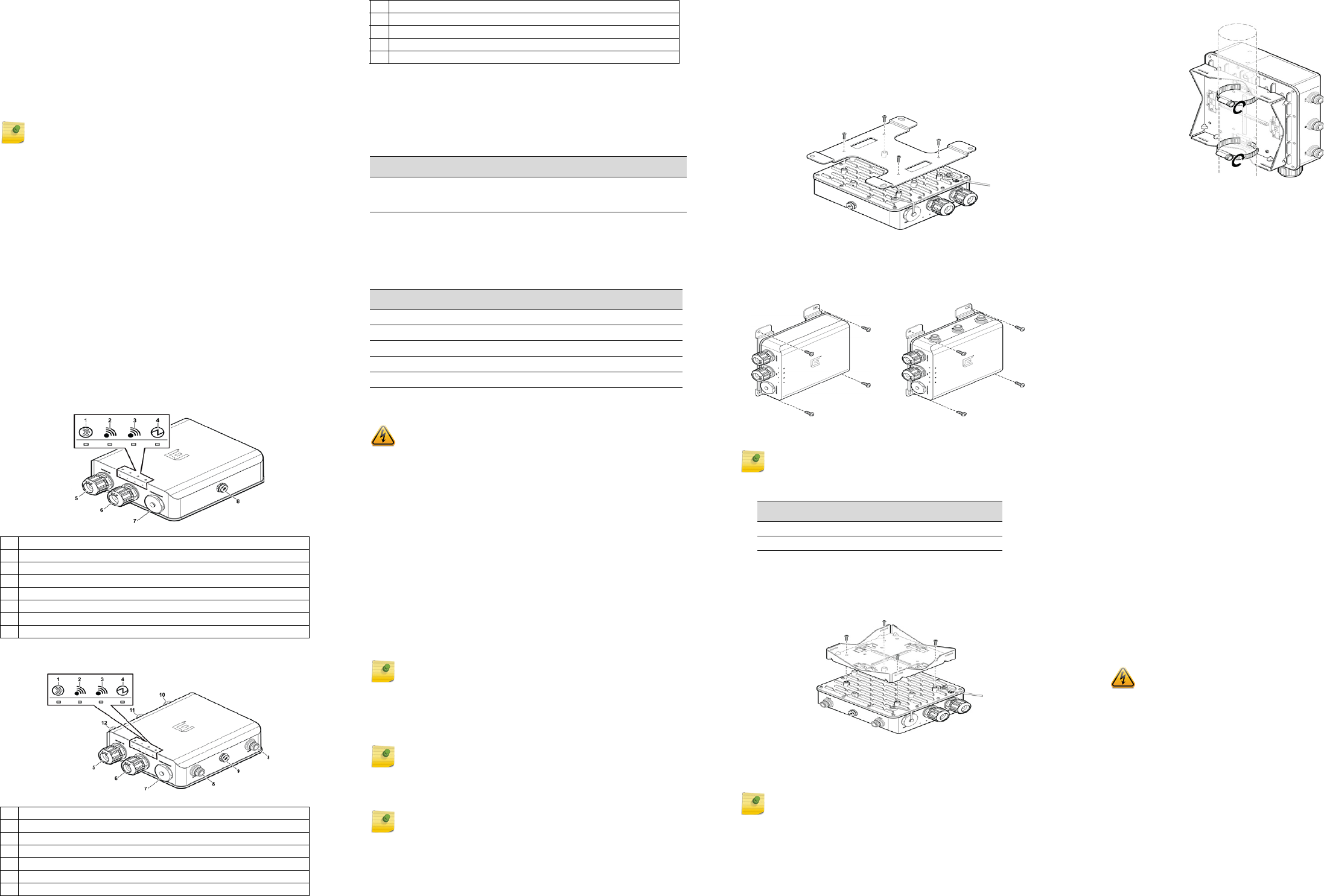
Figure 1 indicates AP3917i. In Figure 2, you can see AP3917e.
Figure 1 Top and Side Views of AP3917i
Figure 2 Top and Side Views of AP3917e
Note: The AP3917i/e requires a minimum base firmware of 10.41.
1IoT/BLE Radio
2Radio - 5 GHz
3Radio - 2.4 GHz
4Status
5GE1 (PoE IN)
6GE2
7Console/Reset
8Vent
1IoT/BLE Radio
2Radio - 5 GHz
3Radio - 2.4 GHz
4Status
5GE1 (PoE IN)
6GE2
7Console/Reset
LEDs on the Front of the AP
Both the Radio LEDs will be Green when they are ON and the LEDs will not
have any lights when they are OFF. Blue LED indicates the IoT status.
For detailed installation information about the AP3917i/e, see the
ExtremeWireless AP3917i/e Installation Guide.
Table 1 shows ways to power the AP3917i/e.
Table 1 Powering the AP3917i/e
Verifying the AP3917i/e Box Contents
Verify the contents of the box and ensure that the following items are
available:
Mounting and Connecting the AP
Use these instructions as guidelines for mounting and connecting the
AP3917i/e easily and safely.
The AP3917i/e mounting brackets are sold separately.
For more information about installing the optional bracket and the adapter,
see the ExtremeWireless AP3917i/e Installation Guide.
For installation videos of the AP, see www.extremenetworks.com/support/.
Mounting the AP3917i/e
The installation of the AP3917i/e should be performed by a professional
installer to ensure proper operation and compliance with local safety
guidelines.
The access point can be mounted to a wall, girder, ceiling, pole or vehicle
using the appropriate bracket.
Positioning the AP for Installation
Mount the AP so that the glands are on the side of the AP closest to the
ground, and not above the plastic cover. You must provide a 3-inch drip loop
on all cables.
Attach the Ground Wire
Use the M4 ground screw assembly, with the star washer, to attach the
ground wire’s ring terminal to the back of the AP. The wire should be as close
to the AP bottom as possible. Tighten the screw to a torque of 13.0-13.5 in-
lbs.
Mounting the AP3917i/e to a Wall
1 Using the mounting bracket as a guide, mark the location for the
mounting screws. The wall bracket provides eight attachment holes. Use
four (one in each corner), Place the bracket and mark the four hole
centers.
2 Drill four holes into the wall as follows:
82.4 G - Antenna 1 and 2
9Vent
10 5G - Antenna 1
11 BLE/802.15.4 Antenna
12 5 G - Antenna 2
Power Source Description
Power over
Ethernet
(PoE) Power is provided through the RJ45 Ethernet port (GE1 port).
Table 2 Contents of the AP3917i/e Box
Quantity Item
1AP3917i/e Quick Reference Guide
1 Cloud Quick Start Card
The following hardware is included:
1 M4 screw assembly with star washer
1 Ring terminal
Electrical Hazard: Only qualified personnel should perform
installation procedures.
Note: Do not remove the dust cap until you need to install the BLE/
IoT antennas.
Note: Attach the H bracket after attaching the ground wire onto the
AP. Once you tighten the torque, tighten the ground screws, and
attach the LAN cable.
Note: The “H” type Mounting Bracket (WS-MBO-H01) is sold as a
separate accessory (ordering part #30519).
– for installing the AP on a masonry wall, use a 5/16” diameter bit.
– for other materials, use the appropriate drill for the screws being used.
3 For masonry installations, drill at least 1/8” (3mm) past the depth of the
screw, or bolt, being used, and place four anchor assemblies into the
holes.
4 Attach the AP to the “H” Bracket:
a Use 4 M4 screw assemblies to attach the AP to the “H” bracket on the
side that does not have the PEM stand-offs.
b Tighten the four screws to a torque of 13.0-13.5 in-lbs.
Figure 3 Attaching the “H” Bracket to the AP
5 Secure the anchors to the wall, then secure the bracket to the anchors.
6 If using #10 screws, tighten them to a torque of 25 in-lbs. If using ¼”
screws, tighten them to 45 in-lbs.
Figure 4 AP3917i/AP3917e Wall Mount “H” Bracket
Mounting the AP3917i/e to a Pole
1 Determine the diameter of the pole.
For other pole diameters, provide your own stainless steel cable clamp.
The band must be ½” (12.7mm) wide.
2 Attach the AP to the “Pole Mount” bracket using four M4 screws. Tighten
the four screws to a torque of 13.0-13.5 in-lbs.
Figure 5 Attaching a Pole Bracket to the AP
3 Attach the cable clamp to the pole bracket. Open the cable clamp by
turning a flat bladed screwdriver counterclockwise. Then, insert the non-
clamp end into the pole bracket through the holes.
4 Put the metal band around the pole and insert it into the clamp. Turn the
clamp screw clockwise, tightening the band around the pole.
Note: The Pole Mounting Bracket (WS-MBO-POLE01) is sold as a
separate accessory (ordering part #30520).
Pole Diameter Cable Clamp Size
<= 2.5” (63.5mm) Use small cable clamp.
5” - 7” (178mm) Use large cable clamp
Note: It is easier to install both clamps before attaching to the pole.
Figure 6 AP with Mounting Bracket—Vertical Pole
Mounting the AP3917i/e to a Wall/Pole using
the WS-MBO-ART01 2 Axis Extension Arm
You can mount the AP3917i/e to a wall or a pole using a 10” extension arm
(WS-MBO-ART01, ordering part #30514). For mounting and installation
instructions, refer to the ExtremeWireless AP3917i/e Installation Guide.
Installing External Antennas
1 Professionally install the external antennas intended for area coverage.
For information about antenna selection and installation, refer to the
External Antenna Site Preparation and Installation Guide.
2 Attach the external antenna cables to the Standard Polarity Type-N
connectors on the AP3917i/e.
Connecting a Power Source to the AP3917i/e
If you need to power the AP3917i/e, you can do so my using the GE1 port on
the AP. The power LED on the front face of the AP illuminates when the device
is connected to a power source. Refer to the ExtremeWireless AP3917i/e
Installation Guide for information.
LAN/Console Connections
The AP3917i/e has one LAN (Ethernet) port and a Console port. Refer to
Figure 1 for the location of these ports. During administration and
maintenance through the LAN or Console, the AP must still have a power
connection through either an Ethernet PoE cable or a DC power supply.
Professional Installation Instruction
Installation personnel
This product is designed for specific application and needs to be installed by a
qualified personnel who has RF and related rule knowledge. The general user
shall not attempt to install or change the setting.
Installation location
The product shall be installed at a location where the radiating antenna can be
kept 20 cm for AP3917i and 35 cm for AP3917e (FCC) and 20 cm for AP3917i
and 42 cm for AP3917e (ISED) from nearby person in normal operation
condition to meet regulatory RF exposure requirement.
External antenna
Use only the antennas which have been approved by the applicant. The non-
approved antenna(s) may produce unwanted spurious or excessive RF
transmitting power which may lead to the violation of FCC/ISED limit and is
prohibited.
Installation procedure
Please refer to user’s manual for the detail.
Instructions d'installation professionnelle
Installation
Ce produit est destine a un usage specifique et doit etre installe par un
personnel qualifie maitrisant les radiofrequences et les regles s'y rapportant.
L'installation et les reglages ne doivent pas etre modifies par l'utilisateur final.
Emplacement d'installation
En usage normal, afin de respecter les exigences reglementaires concernant
l'exposition aux radiofrequences, ce produit doit etre installe de facon a
respecter une distance de 20 cm pour AP3917i et 35cm pour AP3917e (FCC)
et 20 cm pour AP3917i et 42cm pour AP3917e (ISED) entre l'antenne
emettrice et les personnes.
Antenn externe
Utiliser uniiquement les antennes approuvees par le fabricant. L'utilisation
d'autres antennes peut conduire a un niveau de rayonnement essentiel ou non
Warning: Please carefully select the installation position and make sure that
the final output power does not exceed the limit set force in relevant rules. The
violation of the rule could lead to serious federal penalty.
ExtremeWirelessTM
Access Points
Quick Reference
P/N 31050 WS-AP3917i-FCC
P/N 31051 WS-AP3917i-ROW
P/N 31055 WS-AP3917e-FCC
P/N 31056 WS-AP3917e-ROW
Notice
Copyright © 2017 Extreme Networks, Inc. All Rights Reserved.
Legal Notices
Extreme Networks, Inc., on behalf of or through its wholly-owned subsidiary,
Enterasys Networks, Inc., reserves the right to make changes in specifications
and other information contained in this document and its website without
prior notice. The reader should in all cases consult representatives of Extreme
Networks to determine whether any such changes have been made.
The hardware, firmware, software or any specifications described or referred
to in this document are subject to change without notice.
Trademarks
Extreme Networks and the Extreme Networks logo are trademarks or
registered trademarks of Extreme Networks, Inc. in the United States and/or
other countries.
All other names (including any product names) mentioned in this document
are the property of their respective owners and may be trademarks or
registered trademarks of their respective companies/owners.
For additional information on Extreme Networks trademarks, please see:
www.extremenetworks.com/company/legal/trademarks/
Documentation & Support
For product support, including documentation, visit:
www.extremenetworks.com/support/
essentiel depassant les niveaux limites definis par FCC/ISED, ce qui est
interdit.
Procedure d'installation
Consulter le manuel d'utilisation.
Regulatory and Compliance Information
Safety Guidelines
This section contains notices that are intended to protect your personal safety
and prevent damage to the equipment.
Qualified Personnel:
Federal Communications Commission (FCC) Notice
This equipment has been tested and found to comply with the limits for a
Class B digital device, pursuant to Part 15 of the FCC Rules. These limits are
designed to provide reasonable protection against harmful interference in a
residential installation. This equipment generates, uses and can radiate radio
frequency energy and, if not installed and used in accordance with the
instructions, may cause harmful interference to radio communications.
However, there is no guarantee that interference will not occur in a particular
installation. If this equipment does cause harmful interference to radio or
television reception, which can be determined by turning the equipment off
and on, the user is encouraged to try to correct the interference by one of the
following measures:
• Reorient or relocate the receiving antenna.
• Increase the separation between the equipment and receiver.
• Connect the equipment into an outlet on a circuit different from that to
which the receiver is connected.
• Consult the dealer or an experienced radio/TV technician for help.
This device complies with Part 15 of the FCC Rules. Operation is subject to the
following two conditions: (1) This device may not cause harmful interference,
and (2) this device must accept any interference received, including
interference that may cause undesired operation.
This transmitter must not be co-located or operating in conjunction with any
other antenna or transmitter.
This device meets all the other requirements specified in Part 15E, Section
15.407 of the FCC Rules.
Industry Canada Notice
This device complies with ISED’s licence-exempt RSSs. Operation is subject to
the following two conditions: (1) This device may not cause harmful
interference, and (2) this device must accept any interference received,
including interference that may cause undesired operation.
Le présent appareil est conforme aux CNR d’ ISED applicables aux appareils
radio exempts de licence. L’exploitation est autorisée aux deux conditions
suivantes : (1) le dispositif ne doit pas produire de brouillage préjudiciable, et
(2) ce dispositif doit accepter tout brouillage reçu, y compris un brouillage
susceptible de provoquer un fonctionnement indésirable.
Caution :
1 The device for operation in the band 5150-5250 MHz is only for indoor use
to reduce the potential for harmful interference to co-channel mobile
satellite systems;
2 The maximum antenna gain permitted for devices in the band 5725-5850
MHz shall be such that the equipment still complies with the e.i.r.p. limits
specified for point-to-point and non-point-to-point operation as
appropriate; and
3 Users should also be advised that high-power radars are allocated as
primary users (i.e. priority users) of the bands 5650-5850 MHz and that
these radars could cause interference and/or damage to LE-LAN devices.
Avertissement:
1 les dispositifs fonctionnant dans la bande 5150-5250 MHz sont réservés
uniquement pour une utilisation à l’intérieur afin de réduire les risques de
brouillage préjudiciable aux systèmes de satellites mobiles utilisant les
mêmes canaux;
Warning: Avertissement: Choisir avec soin la position d'installation et
s'assurer que la puissance de sortie ne depasse pas les limites en vigueur. La
violation de cette regle peut conduire a de serieuses penalites federales.
Electrical Hazard: Only qualified personnel should perform
installation procedures. Within the context of the safety notes in this
documentation, qualified persons are defined as persons who are
authorized to commission, ground and label devices, systems, and
circuits in accordance with established safety practices and
standards. A qualified person understands the requirements and risks
involved with installing electrical equipment in accordance with
national codes.
Caution: Any changes or modifications not expressly approved by
the party responsible for compliance could void the user's authority
to operate this equipment.
Warning: FCC Radiation Exposure Statement: This equipment
complies with FCC radiation exposure limits set forth for an
uncontrolled environment. This equipment should be installed and
operated with minimum distance 20 cm for AP3917i and 35 cm for
AP3917e between the radiator & your body.
2 le gain maximal d'antenne permis (pour les dispositifs utilisant la bande de
5725 à 5 850 MHz) doit être conforme à la limite de la p.i.r.e. spécifiée pour
l'exploitation point à point et l’exploitation non point à point, selon le cas;
3 De plus, les utilisateurs devraient aussi être avisés que les utilisateurs de
radars de haute puissance sont désignés utilisateurs principaux (c.-à-d.,
qu’ils ont la priorité) pour les bandes 5650-5850 MHz et que ces radars
pourraient causer du brouillage et/ou des dommages aux dispositifs LAN-
EL.
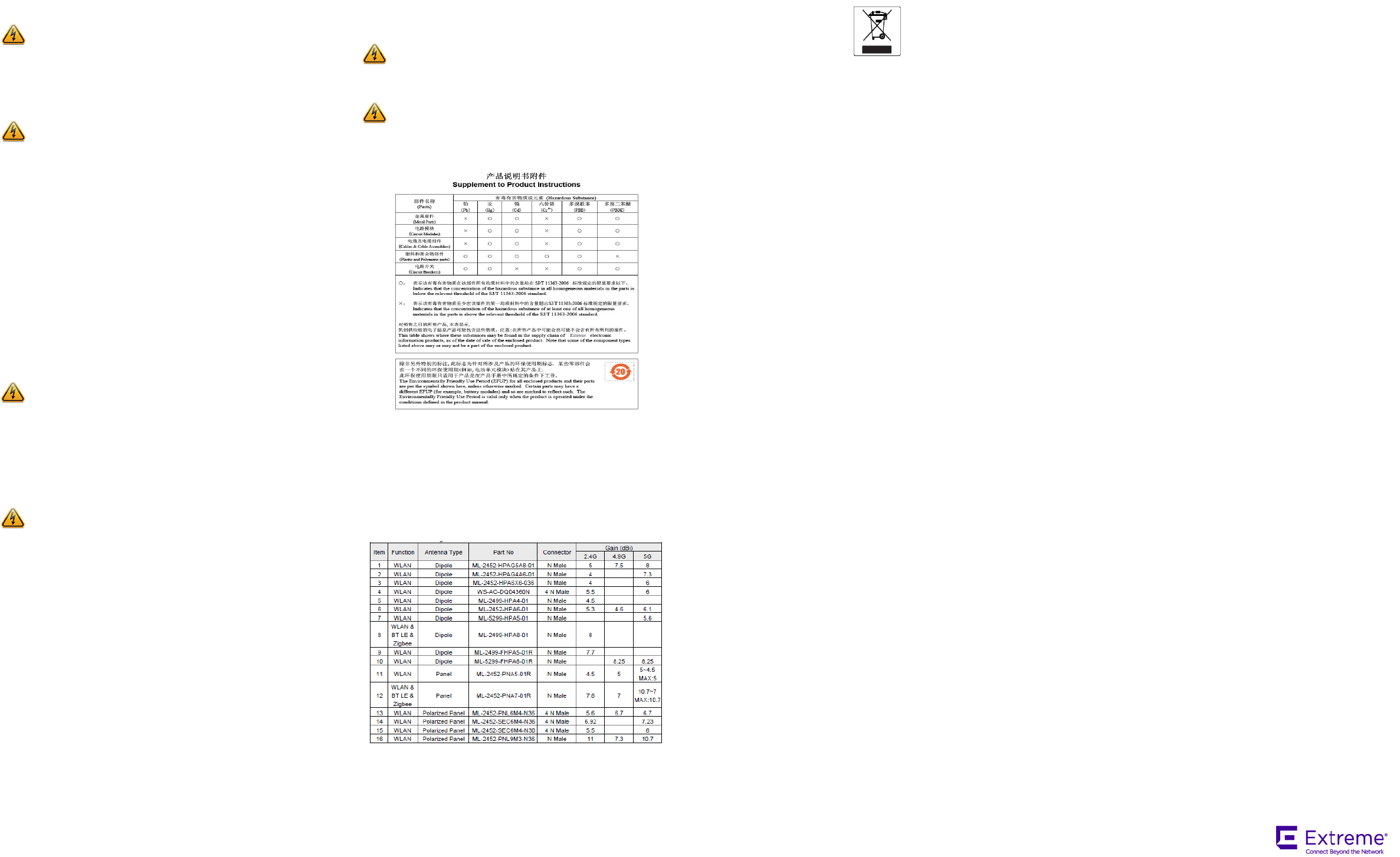
This radio transmitter (IC: 4141B-AP3917E/ Model: AP3917e & AP7662) has
been approved by ISED to operate with the antenna type listed below with
maximum permissible gain indicated. Antenna types not included in this list,
having a gain greater than the maximum gain indicated for that type, are
strictly prohibited for use with this device.
Le présent émetteur radio (IC: 4141B-AP3917E/ Model: AP3917e & AP7662) a
été approuvé par ISED pour fonctionner avec les types d'antenne énumérés
ci-dessous et ayant un gain admissible maximal. Les types d'antenne non
inclus dans cette liste, et dont le gain est supérieur au gain maximal indiqué,
sont strictement interdits pour l'exploitation de l'émetteur.
4.9G Antenna for Item 6 and Item 11 will be secondary primary permanent
fixed operations use only.
Warning: IC Radiation Exposure Statement: This equipment
complies with ISED radiation exposure limits set forth for an
uncontrolled environment. This equipment should be installed and
operated with minimum distance 20 cm for AP3917i and 42 cm for
AP3917e between the radiator & your body.
Warning: Déclaration d'exposition aux radiations: Cet
équipement est conforme aux limites d'exposition aux rayonnements
ISED établies pour un environnement non contrôlé. Cet équipement
doit être installé et utilisé avec un minimum de 20 cm pour AP3917i et
42 cm pourAP3917e de distance entre la source de rayonnement et
votre corps.
European Waste Electrical and Electronic Equipment
(WEEE) Notice
In accordance with Directive 2012/19/EU of the European Parliament on waste
electrical and electronic equipment (WEEE):
1 The symbol above indicates that separate collection of electrical and electronic
equipment is required.
2 When this product has reached the end of its serviceable life, it cannot be disposed of
as unsorted municipal waste. It must be collected and treated separately.
3 It has been determined by the European Parliament that there are potential negative
effects on the environment and human health as a result of the presence of hazardous
substances in electrical and electronic equipment.
4 It is the users’ responsibility to utilize the available collection system to ensure WEEE
is properly treated.
For information about the available collection system, please contact
Extreme Customer Support at +353 61 705500 (Ireland).
Hazardous Substances
This product complies with the requirements of Directive 2011/65/EU of the
European Parliament and of the Council of 8 June 2011 on the restriction of the
use of certain hazardous substances in electrical and electronic equipment.
Declaration of Conformity in Languages of the
European Community
English Hereby, Extreme Networks, declares that this Radio LAN device is in
compliance with the essential requirements and other relevant
provisions of Directive 1999/5/EC.
Finnish Valmistaja Extreme Networks vakuuttaa täten että Radio LAN device
tyyppinen laite on direktiivin 1999/5/EY oleellisten vaatimusten ja sitä
koskevien direktiivin muiden ehtojen mukainen.
Dutch Hierbij verklaart Extreme Networks dat het toestel Radio LAN device
in overeenstemming is met de essentiële eisen en de andere relevante
bepalingen van richtlijn 1999/5/EG.
Bij deze verklaart Extreme Networks dat deze Radio LAN device
voldoet aan de essentiële eisen en aan de overige relevante
bepalingen van Richtlijn 1999/5/EC.
French Par la présente Extreme Networks déclare que l'appareil Radio LAN
device est conforme aux exigences essentielles et aux autres
dispositions pertinentes de la directive 1999/5/CE.
Par la présente, Extreme Networks déclare que ce Radio LAN device
est conforme aux exigences essentielles et aux autres dispositions de
la directive 1999/5/CE qui lui sont applicables.
Swedish Härmed intygar Extreme Networks att denna Radio LAN device står I
överensstämmelse med de väsentliga egenskapskrav och övriga
relevanta bestämmelser som framgår av direktiv 1999/5/EG.
Danish Undertegnede Extreme Networks erklærer herved, at følgende udstyr
Radio LAN device overholder de væsentlige krav og øvrige relevante
krav i direktiv 1999/5/EF.
German Hiermit erklärt Extreme Networks die Übereinstimmung des "WLAN
Wireless Controller bzw. Access Points" mit den grundlegenden
Anforderungen und den anderen relevanten Festlegungen der
Richtlinie 1999/5/EG.
Greek ΜΕ ΤΗΝ ΠΑΡΟΥΣΑ Extreme Networks ∆ΗΛΩΝΕΙ ΟΤΙ Radio LAN
device ΣΥΜΜΟΡΦΩΝΕΤΑΙ ΠΡΟΣ ΤΙΣ ΟΥΣΙΩ∆ΕΙΣ ΑΠΑΙΤΗΣΕΙΣ
ΚΑΙ ΤΙΣ ΛΟΙΠΕΣ ΣΧΕΤΙΚΕΣ ∆ΙΑΤΑΞΕΙΣ ΤΗΣ Ο∆ΗΓΙΑΣ 1999/5/
ΕΚ.
Icelandic Extreme Networks lysir her med yfir að thessi bunadur, Radio LAN
device, uppfyllir allar grunnkrofur, sem gerdar eru i R&TTE tilskipun
ESB nr 1999/5/EC.
Italian Con la presente Extreme Networks dichiara che questo Radio LAN
device è conforme ai requisiti essenziali ed alle altre disposizioni
pertinenti stabilite dalla direttiva 1999/5/CE.
Spanish Por medio de la presente Extreme Networks declara que el Radio LAN
device cumple con los requisitos esenciales y cualesquiera otras
disposiciones aplicables o exigibles de la Directiva 1999/5/CE.
Portuguese Extreme Networks declara que este Radio LAN device está conforme
com os requisitos essenciais e outras disposições da Directiva 1999/5/
CE.
Malti Hawnhekk, Extreme Networks, jiddikjara li dan Radio LAN device
jikkonforma mal-htigijiet essenzjali u ma provvedimenti ohrajn
relevanti li hemm fid-Dirrettiva 1999/5/EC.
P/N 9035165-03