Extreme Networks AP3917E Wireless 802.11 a/ac+b/g/n Access Point User Manual WiNG 5 9 1 System Reference Guide Part 1
Extreme Networks, Inc. Wireless 802.11 a/ac+b/g/n Access Point WiNG 5 9 1 System Reference Guide Part 1
Contents
- 1. User Manual-AP3917e
- 2. User Manual-AP7662
- 3. User Manual-AP3917e R1
- 4. User Manual-AP7662 R1
- 5. WiNG 5.9.1 System Reference Guide Part 1
- 6. WiNG 5.9.1 System Reference Guide Part 2
- 7. WiNG 5.9.1 System Reference Guide Part 3
- 8. WiNG 5.9.1 System Reference Guide Part 4
- 9. WiNG 5.9.1 CLI Reference Guide Part 1
- 10. WiNG 5.9.1 CLI Reference Guide Part 2
- 11. Extreme Wireless V10.41.06 User Guide Part 1
- 12. AP3917 User Manual
- 13. AP7662 User Manual
WiNG 5.9.1 System Reference Guide Part 1

WiNG™ 5.9.1
Wireless Controller and Service Platform
System Reference Guide
Published September 2017
9035204
Published September 2017
9035204
9035204
Copyright © 2017 Extreme Networks, Inc. All Rights Reserved.
Legal Notices
Extreme Networks, Inc. reserves the right to make changes in specifications and other
information contained in this document and its website without prior notice. The reader
should in all cases consult representatives of Extreme Networks to determine whether any
such changes have been made.
The hardware, firmware, software or any specifications described or referred to in this
document are subject to change without notice.
Trademarks
Extreme Networks and the Extreme Networks logo are trademarks or registered
trademarks of Extreme Networks, Inc. in the United States and/or other countries.
All other names (including any product names) mentioned in this document are the
property of their respective owners and may be trademarks or registered trademarks of
their respective companies/owners.
For additional information about Extreme Networks trademarks, go to:
www.extremenetworks.com/company/legal/trademarks/
Support
For product support, including documentation, visit: www.extremenetworks.com/support/

i
Wireless Controller and Service Platform System Reference Guide
Table of Contents
About This Guide
Chapter 1, Overview
1.1 Distributed Intelligence ................................................................................................................................................................................................1-2
1.2 High Availability Networks .........................................................................................................................................................................................1-2
1.3 Gap Free Security ..........................................................................................................................................................................................................1-2
1.4 Outdoor Wireless and Mesh Networking .............................................................................................................................................................1-2
1.5 Network Services, Routing and Switching ..........................................................................................................................................................1-3
1.6 Management, Deployment and Troubleshooting ............................................................................................................................................1-3
Chapter 2, Web UI Features
2.1 Accessing the Web UI ..................................................................................................................................................................................................2-1
2.1.1 Browser and System Requirements ...........................................................................................................................................................2-1
2.1.2 Connecting to the Web UI .............................................................................................................................................................................2-1
2.2 Glossary of Icons Used ..............................................................................................................................................................................................2-2
2.2.1 Global Icons .........................................................................................................................................................................................................2-3
2.2.2 Dialog Box Icons ..............................................................................................................................................................................................2-3
2.2.3 Table Icons ........................................................................................................................................................................................................ 2-4
2.2.4 Status Icons ...................................................................................................................................................................................................... 2-4
2.2.5 Configurable Objects .................................................................................................................................................................................... 2-5
2.2.6 Configuration Objects ...................................................................................................................................................................................2-7
2.2.7 Configuration Operation Icons .................................................................................................................................................................. 2-8
2.2.8 Access Type Icons .......................................................................................................................................................................................... 2-8
2.2.9 Administrative Role Icons ........................................................................................................................................................................... 2-9
2.2.10 Device Icons .................................................................................................................................................................................................... 2-9
Chapter 3, Quick Start
3.1 Using the Initial Setup Wizard ..................................................................................................................................................................................3-1
Chapter 4, Dashboard
4.1 Summary .......................................................................................................................................................................................................................... 4-1
4.1.1 Device Listing ..................................................................................................................................................................................................... 4-2
4.2 System Screen ............................................................................................................................................................................................................. 4-3
4.2.1 Health ................................................................................................................................................................................................................... 4-3
4.2.2 Inventory ............................................................................................................................................................................................................ 4-5
4.3 RF Domain Screen .....................................................................................................................................................................................................4-6
4.3.1 RF Domain Health ........................................................................................................................................................................................... 4-7
4.3.2 RF Domain Inventory ....................................................................................................................................................................................4-9
4.4 Controller .......................................................................................................................................................................................................................4-11
4.4.1 Controller Health .............................................................................................................................................................................................4-11
4.4.2 Controller Inventory .....................................................................................................................................................................................4-13
4.4.3 T5 Controller Dashboard ..........................................................................................................................................................................4-15
4.4.4 EX3500 Switch Dashboard .....................................................................................................................................................................4-21
4.5 Access Point Screen ................................................................................................................................................................................................4-24
4.5.1 Access Point Health .....................................................................................................................................................................................4-24
4.5.2 Access Point Inventory ..............................................................................................................................................................................4-26
4.6 Network View ............................................................................................................................................................................................................4-27
4.7 Debug Wireless Clients ..........................................................................................................................................................................................4-29

Table of Contents
Wireless Controller and Service Platform System Reference Guide ii
4.8 Debug Captive Portal Clients ...............................................................................................................................................................................4-31
4.9 Packet Capture ..........................................................................................................................................................................................................4-32
Chapter 5, Device Configuration
5.1 Basic Configuration ..................................................................................................................................................................................................... 5-2
5.2 Basic Device Configuration ..................................................................................................................................................................................... 5-3
5.2.1 License Configuration .....................................................................................................................................................................................5-7
5.2.2 Assigning Certificates ..................................................................................................................................................................................5-10
5.2.3 Port Mirroring (NX4524 and NX6524 Service Platforms only) .................................................................................................5-29
5.2.4 Wired 802.1x Configuration .....................................................................................................................................................................5-30
5.2.5 RF Domain Overrides ..................................................................................................................................................................................5-32
5.2.6 Profile Overrides ...........................................................................................................................................................................................5-38
5.2.7 Profile Interface Override Configuration ..............................................................................................................................................5-51
5.2.8 Overriding a Profile’s Network Configuration ................................................................................................................................. 5-114
5.2.9 Overriding a Profile’s Security Configuration ................................................................................................................................ 5-202
5.3 Auto Provisioning Policies ................................................................................................................................................................................. 5-268
5.3.1 Configuring an Auto-Provisioning Policy ......................................................................................................................................... 5-270
5.4 Managing an Event Policy ...................................................................................................................................................................................5-275
5.5 Managing MINT Policies ...................................................................................................................................................................................... 5-276
Chapter 6, Wireless Configuration
6.1 Wireless LAN Policy .................................................................................................................................................................................................... 6-2
6.1.1 Basic WLAN Configuration........................................................................................................................................................................... 6-4
6.1.2 Configuring WLAN Security ....................................................................................................................................................................... 6-7
6.1.3 Configuring WLAN Firewall Support ....................................................................................................................................................6-27
6.1.4 Configuring Client Settings .......................................................................................................................................................................6-35
6.1.5 Configuring WLAN Accounting Settings ............................................................................................................................................6-39
6.1.6 Configuring WLAN Service Monitoring Settings ............................................................................................................................. 6-40
6.1.7 Configuring Client Load Balancing Settings .......................................................................................................................................6-42
6.1.8 Configuring Advanced WLAN Settings .............................................................................................................................................. 6-44
6.1.9 Configuring Auto Shutdown Settings ................................................................................................................................................. 6-49
6.2 Configuring WLAN QoS Policies .........................................................................................................................................................................6-51
6.2.1 Configuring a WLAN’s QoS WMM Settings ........................................................................................................................................6-53
6.2.2 Configuring Rate Limit Settings ............................................................................................................................................................6-58
6.2.3 Configuring Multimedia Optimization Settings .............................................................................................................................. 6-64
6.2.4 WLAN QoS Deployment Considerations .......................................................................................................................................... 6-66
6.3 Radio QoS Policy ..................................................................................................................................................................................................... 6-66
6.3.1 Configuring Radio QoS Policies ...............................................................................................................................................................6-68
6.3.2 Radio QoS Configuration and Deployment Considerations .......................................................................................................6-76
6.4 Association ACL ........................................................................................................................................................................................................6-77
6.4.1 Association ACL Deployment Considerations ..................................................................................................................................6-79
6.5 Smart RF Policy .........................................................................................................................................................................................................6-79
6.5.1 Smart RF Configuration and Deployment Considerations .......................................................................................................... 6-90
6.6 MeshConnex Policy ...................................................................................................................................................................................................6-91
6.7 Mesh QoS Policy ........................................................................................................................................................................................................6-97
6.8 Passpoint Policy ......................................................................................................................................................................................................6-104
6.9 Sensor Policy ............................................................................................................................................................................................................. 6-112
Chapter 7, Network Configuration
7.1 Policy Based Routing ...................................................................................................................................................................................................7-1
7.2 L2TP V3 Configuration ............................................................................................................................................................................................. 7-6

Table of Contents
Wireless Controller and Service Platform System Reference Guide iii
7.3 Crypto CMP Policy ...................................................................................................................................................................................................... 7-9
7.4 AAA Policy ................................................................................................................................................................................................................... 7-12
7.5 AAA TACACS Policy ................................................................................................................................................................................................ 7-23
7.6 IPv6 Router Advertisement Policy ....................................................................................................................................................................7-29
7.7 BGP ................................................................................................................................................................................................................................. 7-33
7.7.1 IP Access List ...................................................................................................................................................................................................7-39
7.7.2 AS Path List ......................................................................................................................................................................................................7-41
7.7.3 IP Prefix List ....................................................................................................................................................................................................7-43
7.7.4 Community List .............................................................................................................................................................................................7-44
7.7.5 External Community List ...........................................................................................................................................................................7-46
7.8 Alias ................................................................................................................................................................................................................................7-47
7.8.1 Network Basic Alias ......................................................................................................................................................................................7-48
7.8.2 Network Group Alias .................................................................................................................................................................................... 7-51
7.8.3 Network Service Alias ................................................................................................................................................................................. 7-52
7.9 Application Policy .....................................................................................................................................................................................................7-54
7.10 Application ................................................................................................................................................................................................................7-58
7.11 Application Group ................................................................................................................................................................................................... 7-60
7.12 Schedule Policy ........................................................................................................................................................................................................7-62
7.13 URL Filtering ..............................................................................................................................................................................................................7-63
7.14 Web Filtering ............................................................................................................................................................................................................7-67
7.15 EX3500 QoS Class ..................................................................................................................................................................................................7-68
7.16 EX3500 QoS Policy Map ...................................................................................................................................................................................... 7-72
7.17 Network Deployment Considerations ............................................................................................................................................................ 7-77
Chapter 8, Profile Configuration
8.1 General Profile Configuration ................................................................................................................................................................................. 8-5
8.1.1 General Profile Configuration and Deployment Considerations ................................................................................................... 8-8
8.2 Profile Cluster Configuration (Controllers and Service Platforms) ........................................................................................................ 8-8
8.2.1 Cluster Profile Configuration and Deployment Considerations ...................................................................................................8-11
8.3 Profile Adoption Configuration (APs Only) .....................................................................................................................................................8-11
8.4 Profile Adoption Configuration (Controllers Only) .....................................................................................................................................8-13
8.5 Profile Radio Power (AP7161, AP81XX Only) ..................................................................................................................................................8-16
8.6 Profile 802.1x Configuration ..................................................................................................................................................................................8-18
8.7 Profile Interface Configuration .............................................................................................................................................................................8-19
8.7.1 Ethernet Port Configuration ......................................................................................................................................................................8-19
8.7.2 Virtual Interface Configuration .............................................................................................................................................................. 8-30
8.7.3 Port Channel Configuration ......................................................................................................................................................................8-43
8.7.4 VM Interface Configuration ..................................................................................................................................................................... 8-50
8.7.5 Access Point Radio Configuration .........................................................................................................................................................8-55
8.7.6 WAN Backhaul Configuration ..................................................................................................................................................................8-71
8.7.7 PPPoE Configuration ..................................................................................................................................................................................8-73
8.7.8 Bluetooth Configuration ............................................................................................................................................................................8-76
8.7.9 Profile Interface Deployment Considerations ..................................................................................................................................8-79
8.8 Profile Network Configuration ............................................................................................................................................................................8-79
8.8.1 Setting a Profile’s DNS Configuration .................................................................................................................................................. 8-80
8.8.2 Setting a Profile’s ARP Configuration ...................................................................................................................................................8-81
8.8.3 Setting a Profile’s L2TPV3 Configuration ...........................................................................................................................................8-82
8.8.4 Setting a Profile’s GRE Configuration ..................................................................................................................................................8-92
8.8.5 Setting a Profile’s IGMP Snooping Configuration ...........................................................................................................................8-95
8.8.6 Setting a Profile’s MLD Snooping Configuration .............................................................................................................................8-97
8.8.7 Setting a Profile’s Quality of Service (QoS) Configuration .........................................................................................................8-99
8.8.8 Setting a Profile’s Spanning Tree Configuration ...........................................................................................................................8-103
8.8.9 Setting a Profile’s Routing Configuration ......................................................................................................................................8-106

Table of Contents
Wireless Controller and Service Platform System Reference Guide iv
8.8.10 Setting a Profile’s Dynamic Routing (OSPF) Configuration .................................................................................................... 8-110
8.8.11 Setting a Profile’s Border Gateway Protocol (BGP) Configuration ....................................................................................... 8-129
8.8.12 Setting a Profile’s Forwarding Database Configuration .......................................................................................................... 8-142
8.8.13 Setting a Profile’s Bridge VLAN Configuration .............................................................................................................................8-144
8.8.14 Setting a Profile’s Cisco Discovery Protocol Configuration .................................................................................................... 8-152
8.8.15 Setting a Profile’s Link Layer Discovery Protocol Configuration .......................................................................................... 8-153
8.8.16 Setting a Profile’s Miscellaneous Network Configuration ........................................................................................................ 8-154
8.8.17 Setting a Profile’s Alias Configuration .............................................................................................................................................. 8-155
8.8.18 Setting a Profile’s IPv6 Neighbor Configuration .......................................................................................................................... 8-162
8.8.19 Profile Network Configuration and Deployment Considerations ......................................................................................... 8-164
8.9 Profile Security Configuration ...........................................................................................................................................................................8-164
8.9.1 Setting the Profile’s Security Settings ................................................................................................................................................8-164
8.9.2 Setting the Profile’s Certificate Revocation List (CRL) Configuration ................................................................................. 8-166
8.9.3 Setting the Profile’s Trustpoint Configuration ............................................................................................................................... 8-167
8.9.4 Setting the Profile’s VPN Configuration ........................................................................................................................................... 8-168
8.9.5 Setting the Profile’s Auto IPSec Tunnel Configuration ............................................................................................................... 8-184
8.9.6 Setting the Profile’s NAT Configuration ........................................................................................................................................... 8-186
8.9.7 Setting the Profile’s Bridge NAT Configuration ............................................................................................................................. 8-193
8.9.8 Setting the Profile’s Application Visibility (AVC) Configuration ............................................................................................ 8-195
8.9.9 Profile Security Configuration and Deployment Considerations ........................................................................................... 8-197
8.10 Profile VRRP Configuration .............................................................................................................................................................................. 8-197
8.11 Profile Critical Resources Configuration ....................................................................................................................................................... 8-201
8.12 Profile Services Configuration ........................................................................................................................................................................8-205
8.12.1 Profile Services Configuration and Deployment Considerations ..........................................................................................8-207
8.13 Profile Management Configuration ............................................................................................................................................................... 8-207
8.13.1 Profile Management Configuration and Deployment Considerations ................................................................................. 8-213
8.14 Profile Mesh Point Configuration .................................................................................................................................................................... 8-213
8.14.1 Vehicle Mounted Modem (VMM) Deployment Considerations .............................................................................................. 8-221
8.15 Profile Environmental Sensor Configuration (AP8132 Only) .............................................................................................................. 8-222
8.16 Advanced Profile Configuration .................................................................................................................................................................... 8-224
8.16.1 Client Load Balance Configuration .................................................................................................................................................... 8-224
8.16.2 Configuring MINT Protocol .................................................................................................................................................................. 8-227
8.16.3 Advanced Profile Miscellaneous Configuration ........................................................................................................................... 8-234
Chapter 9, RF Domains
9.1 Managing RF Domains .............................................................................................................................................................................................. 9-2
9.1.1 RF Domain Basic Configuration ................................................................................................................................................................. 9-3
9.1.2 RF Domain Sensor Configuration ............................................................................................................................................................. 9-6
9.1.3 RF Client Name Configuration ................................................................................................................................................................... 9-8
9.1.4 RF Domain Overrides .................................................................................................................................................................................... 9-9
9.1.5 RF Domain Network Alias ...........................................................................................................................................................................9-13
9.1.6 RF Domain Deployment Considerations ..............................................................................................................................................9-21
Chapter 10, Security
10.1 Wireless Firewall ........................................................................................................................................................................................................10-1
10.1.1 Configuring a Firewall Policy ....................................................................................................................................................................10-2
10.1.2 Configuring MAC Firewall Rules ........................................................................................................................................................... 10-15
10.1.3 Firewall Deployment Considerations ................................................................................................................................................10-20
10.2 Configuring IP Firewall Rules ...........................................................................................................................................................................10-20
10.2.1 Setting an IPv4 or IPv6 Firewall Policy .............................................................................................................................................. 10-21
10.2.2 Setting an IP SNMP ACL Policy ...........................................................................................................................................................10-24
10.2.3 Network Group Alias ...............................................................................................................................................................................10-26

Table of Contents
Wireless Controller and Service Platform System Reference Guide v
10.2.4 Network Service Alias ............................................................................................................................................................................. 10-27
10.2.5 EX3500 ACL Standard ...........................................................................................................................................................................10-29
10.2.6 EX3500 ACL Extended ........................................................................................................................................................................... 10-31
10.3 Wireless Client Roles ........................................................................................................................................................................................... 10-33
10.3.1 Configuring a Client’s Role Policy .......................................................................................................................................................10-34
10.4 Device Fingerprinting .........................................................................................................................................................................................10-47
10.5 Intrusion Prevention ............................................................................................................................................................................................. 10-51
10.5.1 Configuring a WIPS Policy ..................................................................................................................................................................... 10-52
10.5.2 Configuring a WIPS Device Categorization Policy ....................................................................................................................... 10-61
10.5.3 Intrusion Detection Deployment Considerations ........................................................................................................................10-64
10.6 EX3500 Time Range ...........................................................................................................................................................................................10-64
Chapter 11, Services
11.1 Configuring Captive Portal Policies ...................................................................................................................................................................... 11-1
11.1.1 Configuring a Captive Portal Policy .......................................................................................................................................................... 11-2
11.1.2 Creating DNS Whitelists ..............................................................................................................................................................................11-13
11.1.3 Captive Portal Deployment Considerations ....................................................................................................................................... 11-14
11.2 Setting the Guest Management Configuration .............................................................................................................................................11-15
11.2.1 Email ....................................................................................................................................................................................................................11-17
11.2.2 SMS .....................................................................................................................................................................................................................11-18
11.2.3 SMS SMTP ...................................................................................................................................................................................................... 11-20
11.2.4 DB Export ........................................................................................................................................................................................................11-22
11.3 Setting the DHCP Configuration ....................................................................................................................................................................... 11-24
11.3.1 Defining DHCP Pools .................................................................................................................................................................................. 11-26
11.3.2 Defining DHCP Server Global Settings ................................................................................................................................................11-35
11.3.3 DHCP Class Policy Configuration ..........................................................................................................................................................11-37
11.3.4 DHCP Deployment Considerations ......................................................................................................................................................11-38
11.4 Setting the Bonjour Gateway Configuration ............................................................................................................................................... 11-39
11.4.1 Configuring a Bonjour Discovery Policy ............................................................................................................................................. 11-39
11.4.2 Configuring a Bonjour Forwarding Policy ......................................................................................................................................... 11-41
11.5 DHCPv6 Server Policy ........................................................................................................................................................................................... 11-43
11.5.1 Defining DHCPv6 Options ........................................................................................................................................................................ 11-45
11.5.2 DHCPv6 Pool Configuration ................................................................................................................................................................... 11-46
11.6 Setting the RADIUS Configuration ................................................................................................................................................................... 11-49
11.6.1 Creating RADIUS Groups .......................................................................................................................................................................... 11-50
11.6.2 Defining User Pools .....................................................................................................................................................................................11-53
11.6.3 Configuring RADIUS Server Policies ....................................................................................................................................................11-57
11.6.4 RADIUS Deployment Considerations ................................................................................................................................................. 11-68
11.7 URL Lists ..................................................................................................................................................................................................................... 11-69
11.7.1 Adding or Editing URL Lists ..................................................................................................................................................................... 11-69
Chapter 12, Management Access
12.1 Viewing Management Access Policies .............................................................................................................................................................. 12-1
12.1.1 Adding or Editing a Management Access Policy .............................................................................................................................. 12-3
12.2 EX3500 Management Policies ......................................................................................................................................................................... 12-19
12.2.1 EX3500 User Groups ................................................................................................................................................................................ 12-20
12.2.2 EX3500 Authentication ...........................................................................................................................................................................12-22
12.2.3 EX3500 Exec Password Management ..............................................................................................................................................12-23
12.2.4 EX3500 System Settings ........................................................................................................................................................................12-25
12.2.5 EX3500 SNMP Management ................................................................................................................................................................ 12-26
12.2.6 EX3500 SNMP Users ............................................................................................................................................................................... 12-30
12.3 Hierarchical Tree .....................................................................................................................................................................................................12-32

Table of Contents
Wireless Controller and Service Platform System Reference Guide vi
12.4 Management Access Deployment Considerations ................................................................................................................................. 12-36
Chapter 13, Diagnostics
13.1 Fault Management ..................................................................................................................................................................................................... 13-1
13.2 Crash Files ................................................................................................................................................................................................................... 13-5
13.3 Advanced Diagnostics ...........................................................................................................................................................................................13-6
13.3.1 UI Debugging ..................................................................................................................................................................................................13-6
13.3.2 Viewing UI Logs ............................................................................................................................................................................................ 13-7
13.3.3 Viewing UI Sessions ....................................................................................................................................................................................13-8
Chapter 14, Operations
14.1 Device Operations .....................................................................................................................................................................................................14-1
14.1.1 Operations Summary ....................................................................................................................................................................................14-1
14.1.2 Adopted Device Upgrades .......................................................................................................................................................................14-4
14.1.3 Using the File Management Browser ..................................................................................................................................................14-10
14.1.4 Restarting Adopted Devices .................................................................................................................................................................. 14-13
14.1.5 Captive Portal Configuration ................................................................................................................................................................. 14-14
14.1.6 Crypto CMP Certificate ........................................................................................................................................................................... 14-18
14.1.7 RAID Operations ......................................................................................................................................................................................... 14-19
14.1.8 Re-elect Controller ..................................................................................................................................................................................... 14-21
14.2 Certificates ............................................................................................................................................................................................................... 14-22
14.2.1 Certificate Management .......................................................................................................................................................................... 14-23
14.2.2 RSA Key Management ............................................................................................................................................................................. 14-31
14.2.3 Certificate Creation .................................................................................................................................................................................. 14-36
14.2.4 Generating a Certificate Signing Request ...................................................................................................................................... 14-38
14.3 Smart RF ...................................................................................................................................................................................................................14-40
14.3.1 Managing Smart RF for an RF Domain .............................................................................................................................................. 14-41
Chapter 15, Statistics
15.1 System Statistics ....................................................................................................................................................................................................... 15-1
15.1.1 Health ..................................................................................................................................................................................................................15-2
15.1.2 Inventory ..........................................................................................................................................................................................................15-4
15.1.3 Adopted Devices ...........................................................................................................................................................................................15-5
15.1.4 Pending Adoptions ......................................................................................................................................................................................15-6
15.1.5 Offline Devices ............................................................................................................................................................................................... 15-7
15.1.6 Device Upgrade .............................................................................................................................................................................................15-9
15.1.7 Licenses ........................................................................................................................................................................................................... 15-10
15.1.8 WIPS Summary .............................................................................................................................................................................................15-12
15.2 RF Domain Statistics ............................................................................................................................................................................................. 15-14
15.2.1 Health ................................................................................................................................................................................................................15-15
15.2.2 Inventory ....................................................................................................................................................................................................... 15-18
15.2.3 Devices .......................................................................................................................................................................................................... 15-20
15.2.4 AP Detection .................................................................................................................................................................................................15-21
15.2.5 Wireless Clients ...........................................................................................................................................................................................15-23
15.2.6 Device Upgrade ..........................................................................................................................................................................................15-25
15.2.7 Wireless LANs ............................................................................................................................................................................................ 15-26
15.2.8 Radios ............................................................................................................................................................................................................ 15-28
15.2.9 Bluetooth ........................................................................................................................................................................................................15-31
15.2.10 Mesh ...............................................................................................................................................................................................................15-33
15.2.11 Mesh Point .................................................................................................................................................................................................. 15-34
15.2.12 SMART RF .................................................................................................................................................................................................. 15-49

Table of Contents
Wireless Controller and Service Platform System Reference Guide vii
15.2.13 WIPS ............................................................................................................................................................................................................ 15-54
15.2.14 Captive Portal .......................................................................................................................................................................................... 15-56
15.2.15 Application Visibility (AVC) ............................................................................................................................................................... 15-58
15.2.16 Coverage Hole Summary ..................................................................................................................................................................... 15-61
15.2.17 Coverage Hole Details .......................................................................................................................................................................... 15-62
15.3 Controller Statistics .............................................................................................................................................................................................. 15-64
15.3.1 Health .............................................................................................................................................................................................................. 15-65
15.3.2 Device ............................................................................................................................................................................................................ 15-67
15.3.3 Cluster Peers ................................................................................................................................................................................................15-71
15.3.4 Web-Filtering ..............................................................................................................................................................................................15-72
15.3.5 Application Visibility (AVC) .................................................................................................................................................................. 15-74
15.3.6 Application Policy ......................................................................................................................................................................................15-77
15.3.7 Device Upgrade ......................................................................................................................................................................................... 15-79
15.3.8 Mirroring .......................................................................................................................................................................................................15-80
15.3.9 Adoption ........................................................................................................................................................................................................ 15-81
15.3.10 AP Detection ........................................................................................................................................................................................... 15-85
15.3.11 Guest User .................................................................................................................................................................................................. 15-86
15.3.12 Wireless LANs ......................................................................................................................................................................................... 15-87
15.3.13 Policy Based Routing ............................................................................................................................................................................ 15-88
15.3.14 Radios .........................................................................................................................................................................................................15-90
15.3.15 Mesh ............................................................................................................................................................................................................. 15-93
15.3.16 Interfaces ................................................................................................................................................................................................... 15-94
15.3.17 Border Gateway Protocol (BGP) Statistics .................................................................................................................................15-105
15.3.18 RAID Statistics .........................................................................................................................................................................................15-114
15.3.19 Power Status ............................................................................................................................................................................................15-116
15.3.20 PPPoE ........................................................................................................................................................................................................ 15-118
15.3.21 OSPF ...........................................................................................................................................................................................................15-120
15.3.22 L2TPv3 ....................................................................................................................................................................................................... 15-131
15.3.23 VRRP ..........................................................................................................................................................................................................15-133
15.3.24 Critical Resources ................................................................................................................................................................................. 15-137
15.3.25 LDAP Agent Status ..............................................................................................................................................................................15-138
15.3.26 Mint Links .................................................................................................................................................................................................15-139
15.3.27 Guest Users ..............................................................................................................................................................................................15-141
15.3.28 GRE Tunnels ...........................................................................................................................................................................................15-143
15.3.29 Dot1x ..........................................................................................................................................................................................................15-144
15.3.30 Network ..................................................................................................................................................................................................15-146
15.3.31 DHCPv6 Relay & Client ........................................................................................................................................................................15-165
15.3.32 DHCP Server ...........................................................................................................................................................................................15-167
15.3.33 Firewall ....................................................................................................................................................................................................15-170
15.3.34 VPN ............................................................................................................................................................................................................15-180
15.3.35 Viewing Certificate Statistics ...........................................................................................................................................................15-183
15.3.36 WIPS Statistics ......................................................................................................................................................................................15-186
15.3.37 Sensor Server ........................................................................................................................................................................................15-188
15.3.38 Bonjour Services ...................................................................................................................................................................................15-189
15.3.39 Captive Portal Statistics ................................................................................................................................................................... 15-190
15.3.40 Network Time ........................................................................................................................................................................................15-192
15.4 Access Point Statistics .......................................................................................................................................................................................15-195
15.4.1 Health .............................................................................................................................................................................................................15-196
15.4.2 Device ...........................................................................................................................................................................................................15-197
15.4.3 Web-Filtering ............................................................................................................................................................................................15-201
15.4.4 Application Visibility (AVC) ...............................................................................................................................................................15-203
15.4.5 Device Upgrade ...................................................................................................................................................................................... 15-206
15.4.6 Adoption ................................................................................................................................................................................................... 15-208
15.4.7 AP Detection .............................................................................................................................................................................................. 15-212

Table of Contents
Wireless Controller and Service Platform System Reference Guide viii
15.4.8 Guest User .................................................................................................................................................................................................. 15-213
15.4.9 Wireless LANs ...........................................................................................................................................................................................15-214
15.4.10 Policy Based Routing ..........................................................................................................................................................................15-216
15.4.11 Radios ......................................................................................................................................................................................................... 15-217
15.4.12 Mesh ............................................................................................................................................................................................................ 15-221
15.4.13 Interfaces ................................................................................................................................................................................................. 15-222
15.4.14 RTLS .......................................................................................................................................................................................................... 15-232
15.4.15 PPPoE ....................................................................................................................................................................................................... 15-233
15.4.16 Bluetooth .................................................................................................................................................................................................15-235
15.4.17 OSPF ..........................................................................................................................................................................................................15-236
15.4.18 L2TPv3 Tunnels .....................................................................................................................................................................................15-246
15.4.19 VRRP .........................................................................................................................................................................................................15-248
15.4.20 Critical Resources ...............................................................................................................................................................................15-250
15.4.21 LDAP Agent Status .............................................................................................................................................................................. 15-251
15.4.22 Mint Links ................................................................................................................................................................................................ 15-252
15.4.23 Guest Users .............................................................................................................................................................................................15-254
15.4.24 GRE Tunnels ..........................................................................................................................................................................................15-256
15.4.25 Dot1x ......................................................................................................................................................................................................... 15-257
15.4.26 Network ..................................................................................................................................................................................................15-259
15.4.27 DHCPv6 Relay & Client .....................................................................................................................................................................15-276
15.4.28 DHCP Server .........................................................................................................................................................................................15-278
15.4.29 Firewall .....................................................................................................................................................................................................15-281
15.4.30 VPN ............................................................................................................................................................................................................15-291
15.4.31 Certificates ..............................................................................................................................................................................................15-294
15.4.32 WIPS .........................................................................................................................................................................................................15-297
15.4.33 Sensor Servers ......................................................................................................................................................................................15-299
15.4.34 Bonjour Services ................................................................................................................................................................................ 15-300
15.4.35 Captive Portal ........................................................................................................................................................................................15-301
15.4.36 Network Time .......................................................................................................................................................................................15-302
15.4.37 Load Balancing .....................................................................................................................................................................................15-305
15.4.38 Environmental Sensors (AP8132 Models Only) ......................................................................................................................15-307
15.5 Wireless Client Statistics ...................................................................................................................................................................................15-310
15.5.1 Health .............................................................................................................................................................................................................. 15-311
15.5.2 Details ........................................................................................................................................................................................................... 15-313
15.5.3 Traffic ............................................................................................................................................................................................................ 15-317
15.5.4 WMM TSPEC ..............................................................................................................................................................................................15-319
15.5.5 Association History ................................................................................................................................................................................15-320
15.5.6 Graph ............................................................................................................................................................................................................ 15-321
15.6 Guest Access Statistics ..................................................................................................................................................................................... 15-322
15.6.1 Guest Access Cumulative Statistics ................................................................................................................................................. 15-323
15.6.2 Social Media Statistics ........................................................................................................................................................................... 15-325
15.6.3 Reports ........................................................................................................................................................................................................15-326
15.6.4 Notifications .............................................................................................................................................................................................. 15-327
15.6.5 Guest Access Database ........................................................................................................................................................................15-329
15.7 Analytics Developer Interface ........................................................................................................................................................................ 15-332
15.7.1 Download REST API Toolkit ................................................................................................................................................................ 15-332
15.7.2 API Assessment ....................................................................................................................................................................................... 15-335
Chapter 16, Analytics
16.1 System Analytics ........................................................................................................................................................................................................16-1
16.2 RF Domain Analytics ..............................................................................................................................................................................................16-8
16.3 Wireless Controller Analytics ............................................................................................................................................................................ 16-12
16.4 Access Point Analytics ......................................................................................................................................................................................... 16-13

Table of Contents
Wireless Controller and Service Platform System Reference Guide ix
16.5 Analytic Event Monitoring .................................................................................................................................................................................. 16-16
Chapter 17, WiNG Events
17.1 Event Messages ........................................................................................................................................................................................................... 17-1
Appendix A, PUBLICLY AVAILABLE SOFTWARE
A.1 General Information ....................................................................................................................................................................................................A-1
A.2 Open Source Software Used .................................................................................................................................................................................A-2
A.3 OSS Licenses ............................................................................................................................................................................................................ A-15
A.3.1 Apache License, Version 2.0 .................................................................................................................................................................... A-15
A.3.2 The BSD License ........................................................................................................................................................................................... A-17
A.3.3 Creative Commons Attribution-ShareAlike License, version 3.0 ............................................................................................. A-18
A.3.4 DropBear License ....................................................................................................................................................................................... A-23
A.3.5 GNU General Public License, version 2 .............................................................................................................................................. A-25
A.3.6 GNU GENERAL PUBLIC LICENSE ........................................................................................................................................................ A-26
A.3.7 GNU Lesser General Public License 2.1 ..............................................................................................................................................A-30
A.3.8 CCO 1.0 Universal ........................................................................................................................................................................................ A-37
A.3.9 GNU General Public License, version 3 ..............................................................................................................................................A-39
A.3.10 ISC License ...................................................................................................................................................................................................A-48
A.3.11 GNU Lesser General Public License, version 3.0 ...........................................................................................................................A-48
A.3.12 GNU General Public License 2.0 .......................................................................................................................................................... A-51
A.3.13 GNU Lesser General Public License, version 2.0 .......................................................................................................................... A-57
A.3.14 GNU Lesser General Public License, version 2.1 ............................................................................................................................A-63
A.3.15 GNU LESSER GENERAL PUBLIC LICENSE .....................................................................................................................................A-65
A.3.16 MIT License ..................................................................................................................................................................................................A-69
A.3.17 Mozilla Public License, version 2 .........................................................................................................................................................A-70
A.3.18 The Open LDAP Public License ...........................................................................................................................................................A-74
A.3.19 OpenSSL License ....................................................................................................................................................................................... A-75
A.3.20 WU-FTPD Software License ................................................................................................................................................................ A-76
A.3.21 zlib License ................................................................................................................................................................................................... A-77
A.3.22 Python License, Version 2 (Python-2.0) ......................................................................................................................................... A-78
A.3.23 BEOPEN.COM LICENSE AGREEMENT FOR PYTHON 2.0 ....................................................................................................... A-78
A.3.24 CNRI OPEN SOURCE LICENSE AGREEMENT (for Python 1.6b1) ......................................................................................... A-79
A.3.25 CWI LICENSE AGREEMENT FOR PYTHON 0.9.0 THROUGH 1.2 ..........................................................................................A-80
A.3.26 Zope Public License (ZPL) Version 2.0 ............................................................................................................................................ A-81
A.3.27 Zope Public License (ZPL) Version 2.1 ............................................................................................................................................. A-82

xi
Wireless Controller and Service Platform System Reference Guide
About This Guide
This manual supports the following Access Point, controller and service platform models:
•Wireless Controllers – RFS4000, RFS6000
•Service Platforms - NX5500, NX5500E, NX7500, NX75XX, NX7510E, NX9500, NX9510, NX9600, NX9610,
VX9000, VX9000E
•Access Points – AP6522, AP6532, AP6562, AP7161, AP7502, AP7522, AP7532, AP7562, AP7602, AP7612,
AP7622, AP7632, AP7662, AP8122, AP8132, AP8163, AP8232, AP8432 and AP8533.
This section is organized into the following:
•Document Convention
•Notational Conventions
•End-User Software License Agreement
NOTE: Throughout this guide, unless specific model references are needed,
AP8122, AP8132, AP8163 models are referred to as AP81XX.
About This Guide
Wireless Controller and Service Platform System Reference Guide xii
Document Convention
The following conventions are used in this manual to draw your attention to important information:
Notational Conventions
The following notational conventions are used in this document:
•Italics are used to highlight specific items in the general text, and to identify chapters and sections in this and
related documents
• Bullets (•) indicate:
- lists of alternatives
- lists of required steps that are not necessarily sequential
-action items
• Sequential lists (those describing step-by-step procedures) appear as numbered lists
NOTE: Indicates tips or special requirements.
CAUTION: Indicates conditions that can cause equipment damage or data loss.
WARNING! Indicates a condition or procedure that could result in personal injury
or equipment damage.
Switch Note: Indicates caveats unique to a particular RFS series controller or NX se-
ries service platform.
!

About This Guide
Wireless Controller and Service Platform System Reference Guide xiii
End-User Software License Agreement
This document is an agreement (“Agreement”) between You, the end user, and Extreme Networks, Inc., on behalf
of itself and its Affiliates (“Extreme”) that sets forth your rights and obligations with respect to the “Licensed
Materials”. BY INSTALLING SOFTWARE AND/OR THE LICENSE KEY FOR THE SOFTWARE (“License Key”)
(collectively, “Licensed Software”), IF APPLICABLE, COPYING, OR OTHERWISE USING THE LICENSED SOFTWARE
AND/OR ANY OF THE LICENSED MATERIALS UNDER THIS AGREEMENT, YOU ARE AGREEING TO BE BOUND BY
THE TERMS OF THIS AGREEMENT, WHICH INCLUDES THE LICENSE(S) AND THE LIMITATION(S) OF WARRANTY
AND DISCLAIMER(S)/LIMITATION(S) OF LIABILITY. IF YOU DO NOT AGREE TO THE TERMS OF THIS AGREEMENT,
RETURN THE LICENSE KEY (IF APPLICABLE) TO EXTREME OR YOUR DEALER, IF ANY, OR DO NOT USE THE
LICENSED SOFTWARE AND/OR LICENSED MATERIALS AND CONTACT EXTREME OR YOUR DEALER WITHIN TEN
(10) DAYS FOLLOWING THE DATE OF RECEIPT TO ARRANGE FOR A REFUND. IF YOU HAVE ANY QUESTIONS
ABOUT THIS AGREEMENT, CONTACT EXTREME, Attn: LegalTeam@extremenetworks.com.
1 DEFINITIONS. “Affiliates” means any person, partnership, corporation, limited liability company, or other form of
enterprise that directly or indirectly through one or more intermediaries, controls, or is controlled by, or is under
common control with the party specified. “Server Application” means the software application associated to
software authorized for installation (per License Key, if applicable) on one or more of Your servers as further
defined in the Ordering Documentation. “Client Application” shall refer to the application to access the Server
Application. “Network Device” for purposes of this Agreement shall mean a physical computer device,
appliance, appliance component, controller, wireless access point, or virtual appliance as further described
within the applicable product documentation, which includes the Order Documentation. “Licensed Materials”
means the Licensed Software (including the Server Application and Client Application), Network Device (if
applicable), Firmware, media embodying software, and the accompanying documentation. “Concurrent User”
shall refer to any of Your individual employees who You provide access to the Server Application at any one
time. “Firmware” refers to any software program or code embedded in chips or other media. “Standalone”
software is software licensed for use independent of any hardware purchase as identified in the Ordering
Documentation. “Licensed Software” collectively refers to the software, including Standalone software,
Firmware, Server Application, Client Application or other application licensed with conditional use parameters
as defined in the Ordering Documentation. “Ordering Documentation” shall mean the applicable price
quotation, corresponding purchase order, relevant invoice, order acknowledgement, and accompanying
documentation or specifications for the products and services purchased, acquired or licensed hereunder from
Extreme either directly or indirectly.
2TERM
. This Agreement is effective from the date on which You accept the terms and conditions of this
Agreement via click-through, commence using the products and services or upon delivery of the License Key if
applicable, and shall be effective until terminated. In the case of Licensed Materials offered on a subscription
basis, the term of “licensed use” shall be as defined within Your Ordering Documentation.
3 GRANT OF LICENSE. Extreme will grant You a non-transferable, non-sublicensable, non-exclusive license to use
the Licensed Materials and the accompanying documentation for Your own business purposes subject to the
terms and conditions of this Agreement, applicable licensing restrictions, and any term, user server networking
device, field of use, or other restrictions as set forth in Your Ordering Documentation. If the Licensed Materials
are being licensed on a subscription and/or capacity basis, the applicable term and/or capacity limit of the
license shall be specified in Your Ordering Documentation. You may install and use the Licensed Materials as
permitted by the license type purchased as described below in License Types. The license type purchased is
specified on the invoice issued to You by Extreme or Your dealer, if any. YOU MAY NOT USE, COPY, OR MODIFY
THE LICENSED MATERIALS, IN WHOLE OR IN PART, EXCEPT AS EXPRESSLY PROVIDED IN THIS AGREEMENT.
4LICENSE TYPES
.

About This Guide
Wireless Controller and Service Platform System Reference Guide xiv
•Single User, Single Network Device. Under the terms of this license type, the license granted to You by
Extreme authorizes You to use the Licensed Materials as bundled with a single Network Device as identified
by a unique serial number for the applicable Term, if and as specified in Your Ordering Documentation, or
any replacement for that network device for that same Term, for internal use only. A separate license, under
a separate License Agreement, is required for any other network device on which You or another individual,
employee or other third party intend to use the Licensed Materials. A separate license under a separate
License Agreement is also required if You wish to use a Client license (as described below).
•Single User, Multiple Network Device. Under the terms of this license type, the license granted to You by
Extreme authorizes You to use the Licensed Materials with a defined amount of Network Devices as defined
in the Ordering Documentation.
•Client. Under the terms of the Client license, the license granted to You by Extreme will authorize You to
install the License Key for the Licensed Materials on your server and allow the specific number of Concurrent
Users as ordered by you and is set forth in Your Ordering Documentation. A separate license is required for
each additional Concurrent User.
•Standalone. Software or other Licensed Materials licensed to You for use independent of any Network
Device.
•Subscription. Licensed Materials, and inclusive Software, Network Device or related appliance updates and
maintenance services, licensed to You for use during a subscription period as defined in Your applicable
Ordering Documentation.
•Capacity. Under the terms of this license, the license granted to You by Extreme authorizes You to use the
Licensed Materials up to the amount of capacity or usage as defined in the Ordering Documentation.
5AUDIT RIGHTS
. You agree that Extreme may audit Your use of the Licensed Materials for compliance with these
terms and Your License Type at any time, upon reasonable notice. In the event that such audit reveals any use
of the Licensed Materials by You other than in full compliance with the license granted and the terms of this
Agreement, Extreme reserves the right to charge You for all reasonable expenses related to such audit in
addition to any other liabilities and overages applicable as a result of such non-compliance, including but not
limited to additional fees for Concurrent Users, excess capacity or usage over and above those specifically
granted to You. From time to time, the Licensed Materials may upload information about the Licensed Materials
and the associated usage to Extreme. This is to verify the Licensed Materials are being used in accordance with
a valid license and/or entitlement. By using the Licensed Materials, you consent to the transmission of this
information.
6 RESTRICTION AGAINST COPYING OR MODIFYING LICENSED MATERIALS. Except as expressly permitted in this
Agreement, You may not copy or otherwise reproduce the Licensed Materials. In no event does the limited
copying or reproduction permitted under this Agreement include the right to decompile, disassemble,
electronically transfer, or reverse engineer the Licensed Materials, including the Licensed Software, or to
translate the Licensed Materials into another computer language. The media embodying the Licensed Materials
may be copied by You, in whole or in part, into printed or machine readable form, in sufficient numbers only for
backup or archival purposes, or to replace a worn or defective copy. However, You agree not to have more than
two (2) copies of the Licensed Software in whole or in part, including the original media, in your possession for
said purposes without Extreme’ prior written consent, and in no event shall You operate more copies of the
Licensed Software than the specific licenses granted to You. You may not copy or reproduce the
documentation. You agree to maintain appropriate records of the location of the original media and all copies
of the Licensed Software, in whole or in part, made by You. Any portion of the Licensed Software included in
any such modular work shall be used only on a single computer for internal purposes and shall remain subject
to all the terms and conditions of this Agreement. You agree to include any copyright or other proprietary
notice set forth on the label of the media embodying the Licensed Software on any copy of the Licensed
Software in any form, in whole or in part, or on any modification of the Licensed Software or any such modular
work containing the Licensed Software or any part thereof.
7 TITLE AND PROPRIETARY RIGHTS

About This Guide
Wireless Controller and Service Platform System Reference Guide xv
a The Licensed Materials are copyrighted works and are the sole and exclusive property of Extreme, any
company or a division thereof which Extreme controls or is controlled by, or which may result from the
merger or consolidation with Extreme (its “Affiliates”), and/or their suppliers. This Agreement conveys a
limited right to operate the Licensed Materials and shall not be construed to convey title to the Licensed
Materials to You. There are no implied rights. You shall not sell, lease, transfer, sublicense, dispose of, or
otherwise make available the Licensed Materials or any portion thereof, to any other party.
bYou further acknowledge that in the event of a breach of this Agreement, Extreme shall suffer severe and
irreparable damages for which monetary compensation alone will be inadequate. You therefore agree that in
the event of a breach of this Agreement, Extreme shall be entitled to monetary damages and its reasonable
attorney’s fees and costs in enforcing this Agreement, as well as injunctive relief to restrain such breach, in
addition to any other remedies available to Extreme.
8 PROTECTION AND SECURITY. In the performance of this Agreement or in contemplation thereof, You and your
employees and agents may have access to private or confidential information owned or controlled by Extreme
relating to the Licensed Materials supplied hereunder including, but not limited to, product specifications and
schematics, and such information may contain proprietary details and disclosures. All information and data so
acquired by You or your employees or agents under this Agreement or in contemplation hereof shall be and
shall remain Extreme’ exclusive property, and You shall use all commercially reasonable efforts to keep, and
have your employees and agents keep, any and all such information and data confidential, and shall not copy,
publish, or disclose it to others, without Extreme’ prior written approval, and shall return such information and
data to Extreme at its request. Nothing herein shall limit your use or dissemination of information not actually
derived from Extreme or of information which has been or subsequently is made public by Extreme, or a third
party having authority to do so
You agree not to deliver or otherwise make available the Licensed Materials or any part thereof, including
without limitation the object or source code (if provided) of the Licensed Software, to any party other than
Extreme or its employees, except for purposes specifically related to your use of the Licensed Materials on a
single computer as expressly provided in this Agreement, without the prior written consent of Extreme. You
acknowledge that the Licensed Materials contain valuable confidential information and trade secrets, and that
unauthorized use, copying and/or disclosure thereof are harmful to Extreme or its Affiliates and/or its/their
software suppliers.
9 MAINTENANCE AND UPDATES. Except as otherwise defined below, updates and certain maintenance and
support services, if any, shall be provided to You pursuant to the terms of an Extreme Service and Maintenance
Agreement, if Extreme and You enter into such an agreement. Except as specifically set forth in such
agreement, Extreme shall not be under any obligation to provide updates, modifications, or enhancements, or
maintenance and support services for the Licensed Materials to You. If you have purchased Licensed Materials
on a subscription basis then the applicable service terms for Your Licensed Materials are as provided in Your
Ordering Documentation. Extreme will perform the maintenance and updates in a timely and professional
manner, during the Term of Your subscription, using qualified and experienced personnel. You will cooperate in
good faith with Extreme in the performance of the support services including, but not limited to, providing
Extreme with: (a) access to the Extreme Licensed Materials (and related systems); and (b) reasonably requested
assistance and information. Further information about the applicable maintenance and updates terms can be
found on Extreme’s website at http://www.extremenetworks.com/company/legal/terms-of-support
10 DEFAULT AND TERMINATION. In the event that You shall fail to keep, observe, or perform any obligation under
this Agreement, including a failure to pay any sums due to Extreme, or in the event that you become insolvent
or seek protection, voluntarily or involuntarily, under any bankruptcy law, Extreme may, in addition to any other
remedies it may have under law, terminate the License and any other agreements between Extreme and You.
a Immediately after any termination of the Agreement, Your licensed subscription term, or if You have for any
reason discontinued use of Licensed Materials, You shall return to Extreme the original and any copies of the
Licensed Materials and remove the Licensed Materials, including an Licensed Software, from any modular

About This Guide
Wireless Controller and Service Platform System Reference Guide xvi
works made pursuant to Section 3, and certify in writing that through your best efforts and to the best of
your knowledge the original and all copies of the terminated or discontinued Licensed Materials have been
returned to Extreme
b Sections 1, 7, 8, 10, 11, 12, 13, 14 and 15 shall survive termination of this Agreement for any reason.
11 EXPORT REQUIREMENTS. You are advised that the Licensed Materials, including the Licensed Software is of
United States origin and subject to United States Export Administration Regulations; diversion contrary to
United States law and regulation is prohibited. You agree not to directly or indirectly export, import or transmit
the Licensed Materials, including the Licensed Software to any country, end user or for any Use that is
prohibited by applicable United States regulation or statute (including but not limited to those countries
embargoed from time to time by the United States government); or contrary to the laws or regulations of any
other governmental entity that has jurisdiction over such export, import, transmission or Use
12 UNITED STATES GOVERNMENT RESTRICTED RIGHTS. The Licensed Materials (i) were developed solely at
private expense; (ii) contain “restricted computer software” submitted with restricted rights in accordance with
section 52.227-19 (a) through (d) of the Commercial Computer Software-Restricted Rights Clause and its
successors, and (iii) in all respects is proprietary data belonging to Extreme and/or its suppliers. For
Department of Defense units, the Licensed Materials are considered commercial computer software in
accordance with DFARS section 227.7202-3 and its successors, and use, duplication, or disclosure by the U.S.
Government is subject to restrictions set forth herein.
13 LIMITED WARRANTY AND LIMITATION OF LIABILITY. Extreme warrants to You that (a) the initially-shipped
version of the Licensed Materials will materially conform to the Documentation; and (b) the media on which the
Licensed Software is recorded will be free from material defects for a period of ninety (90) days from the date
of delivery to You or such other minimum period required under applicable law. Extreme does not warrant that
Your use of the Licensed Materials will be error-free or uninterrupted.
NEITHER EXTREME NOR ITS AFFILIATES MAKE ANY OTHER WARRANTY OR REPRESENTATION, EXPRESS
OR IMPLIED, WITH RESPECT TO THE LICENSED MATERIALS, WHICH ARE LICENSED "AS IS". THE LIMITED
WARRANTY AND REMEDY PROVIDED ABOVE ARE EXCLUSIVE AND IN LIEU OF ALL OTHER WARRANTIES,
INCLUDING IMPLIED WARRANTIES OF MERCHANTABILITY OR FITNESS FOR A PARTICULAR PURPOSE,
WHICH ARE EXPRESSLY DISCLAIMED, AND STATEMENTS OR REPRESENTATIONS MADE BY ANY OTHER
PERSON OR FIRM ARE VOID. IN NO EVENT WILL EXTREME OR ANY OTHER PARTY WHO HAS BEEN
INVOLVED IN THE CREATION, PRODUCTION OR DELIVERY OF THE LICENSED MATERIALS BE LIABLE FOR
SPECIAL, DIRECT, INDIRECT, RELIANCE, INCIDENTAL OR CONSEQUENTIAL DAMAGES, INCLUDING LOSS OF
DATA OR PROFITS OR FOR INABILITY TO USE THE LICENSED MATERIALS, TO ANY PARTY EVEN IF
EXTREME OR SUCH OTHER PARTY HAS BEEN ADVISED OF THE POSSIBILITY OF SUCH DAMAGES. IN NO
EVENT SHALL EXTREME OR SUCH OTHER PARTY'S LIABILITY FOR ANY DAMAGES OR LOSS TO YOU OR
ANY OTHER PARTY EXCEED THE LICENSE FEE YOU PAID FOR THE LICENSED MATERIALS.
Some states do not allow limitations on how long an implied warranty lasts and some states do not allow the
exclusion or limitation of incidental or consequential damages, so the above limitation and exclusion may not
apply to You. This limited warranty gives You specific legal rights, and You may also have other rights which
vary from state to state.
14 JURISDICTION. The rights and obligations of the parties to this Agreement shall be governed and construed in
accordance with the laws and in the State and Federal courts of the State of California, without regard to its
rules with respect to choice of law. You waive any objections to the personal jurisdiction and venue of such
courts. None of the 1980 United Nations Convention on the Limitation Period in the International Sale of Goods,
and the Uniform Computer Information Transactions Act shall apply to this Agreement
15 FREE AND OPEN SOURCE SOFTWARE. Portions of the Software (Open Source Software) provided to you may
be subject to a license that permits you to modify these portions and redistribute the modifications (an Open
Source License). Your use, modification and redistribution of the Open Source Software are governed by the

About This Guide
Wireless Controller and Service Platform System Reference Guide xvii
terms and conditions of the applicable Open Source License. More details regarding the Open Source Software
and the applicable Open Source Licenses are available at www.extremenetworks.com/services/
SoftwareLicensing.aspx. Some of the Open Source software may be subject to the GNU General Public License
v.x (GPL) or the Lesser General Public Library (LGPL), copies of which are provided with the Licensed Materials
and are further available for review at www.extremenetworks.com/services/SoftwareLicensing.aspx, or upon
request as directed herein. In accordance with the terms of the GPL and LGPL, you may request a copy of the
relevant source code. See the Software Licensing web site for additional details. This offer is valid for up to
three years from the date of original download of the software.
16 GENERAL.
a This Agreement is the entire agreement between Extreme and You regarding the Licensed Materials, and all
prior agreements, representations, statements, and undertakings, oral or written, are hereby expressly
superseded and canceled.
b This Agreement may not be changed or amended except in writing signed by both parties hereto.
c You represent that You have full right and/or authorization to enter into this Agreement.
d This Agreement shall not be assignable by You without the express written consent of Extreme. The rights of
Extreme and Your obligations under this Agreement shall inure to the benefit of Extreme’ assignees,
licensors, and licensees.
e Section headings are for convenience only and shall not be considered in the interpretation of this
Agreement
f The provisions of the Agreement are severable and if any one or more of the provisions hereof are judicially
determined to be illegal or otherwise unenforceable, in whole or in part, the remaining provisions of this
Agreement shall nevertheless be binding on and enforceable by and between the parties hereto
g Extreme’s waiver of any right shall not constitute waiver of that right in future. This Agreement constitutes
the entire understanding between the parties with respect to the subject matter hereof, and all prior
agreements, representations, statements and undertakings, oral or written, are hereby expressly superseded
and canceled. No purchase order shall supersede this Agreement.
h Should You have any questions regarding this Agreement, You may contact Extreme at the address set forth
below. Any notice or other communication to be sent to Extreme must be mailed by certified mail to the
following address:
Extreme Networks, Inc.
16480 Via Del
San Jose, CA 95119 United States
Tel: +1 408-579-2800
Toll-free: +1 888-257-3000

1 - 1
Wireless Controller and Service Platform System Reference Guide
1
Overview
Extreme Networks’ WiNG 5 operating system is the next generation in the evolution of WLAN
architectures. WiNG 5 OS is designed to scale efficiently from the smallest networks to large,
geographically dispersed deployments. The co-operative, distributed control plane innovation in the WiNG
5 architecture offers a software-defined networking (SDN)-ready operating system that can distribute
controller functionality to every Access Point in your network. Now, every Access Point is network aware,
providing the intelligence required to truly unleash optimal performance, all wireless LAN infrastructure can
work together to ensure every transmission is routed through the most efficient path, every time.
WiNG 5 brings you the resiliency of a standalone Access Point network without the vulnerability of a
centralized controller, with advancements that take performance, reliability, security, scalability and
manageability to a new level. The result? Maximum network uptime and security with minimal
management. And true seamless and dependable mobility for your users.
WiNG 5 advances the following technology:
Comprehensive Wi-Fi support - WiNG supports all Wi-Fi protocols, including 802.11a/b/g/n/ac, allowing you
to create a cost-effective migration plan based on the needs of your business.
Extraordinary scalability - With WiNG, you can build any size network, from a small WLAN network in a
single location to a large multi-site network that reaches all around the globe.
Extraordinary flexibility - No matter what type of infrastructure you deploy, WiNG 5 delivers intelligence to
all: standalone independent Access Points or adaptive Access Points that can be adopted by a controller
but can switch to independent mode; virtual controllers; physical controllers in branch offices, the network
operating center (NOC) or the cloud.
The power of distributed intelligence - WiNG distributes intelligence right to the network edge, empowering
every controller and Access Point with the intelligence needed to be network-aware, able to identify and
dynamically route traffic over the most efficient path available at that time.
Extraordinary network flexibility and site survivability - WiNG provides the best of both worlds: true
hierarchical management that delivers a new level of management simplicity and resiliency by enabling
controllers to adopt and manage other controllers and Access Points, while allowing adopted infrastructure
to also stand on its own.
Gap-free security - When it comes to security, there can be no compromises. WiNG’s comprehensive
security capabilities keep your network and your data safe, ensuring compliance with PCI, HIPAA and other
government and industry security regulations.
Connectivity for the largest indoor and outdoor spaces - In addition to enabling a robust indoor WLAN, our
patented MeshConnex™ technology enables the extension of Wi-Fi networks to the largest of outdoor
spaces from an expansive outdoor campus environment to an entire city.
Powerful centralized management - With WiNG you get complete control over every aspect of your WLAN.
This single powerful windowpane enables zero touch infrastructure deployment, rich analytics that can help
you recognize and correct brewing issues before they impact service quality and user connectivity, along
with centralized and remote troubleshooting and issue resolution of the entire network.
Application Visibility and Control - With WiNG you get visibility & control over Layer-7 applications with an
embedded DPI engine at the Access Point. Extreme Networks’ NSight (an add-on module to WiNG)

Overview
Wireless Controller and Service Platform System Reference Guide 1 - 2
provides real-time visibility and in-depth insight into every dimension of the network including layer-7
application visibility, client devices, device & OS types and users. At a glance the administrator can discern
the top applications by usage or by count at every level of the network from site level to Access Points and
clients. This is achieved by Deep Packet Inspection (DPI) of every flow of every user at the Access Point.
The embedded DPI engine in the WiNG OS can detect and identify thousands of applications real time and
report to NSight. In addition to detection, firewall and QOS policies can leverage the application context to
enforce policies.
1.1 Distributed Intelligence
WiNG 5 enables all WLAN infrastructure with the intelligence required to work together to determine the
most efficient path for every transmission. The need to route all traffic through a controller is eliminated,
along with the resulting congestion and latency, resulting in higher throughput and superior network
performance. Since all features are available at the access layer, they remain available even when the
controller is offline, for example, due to a WAN outage, ensuring site survivability and extraordinary
network resilience. In addition, you get unprecedented scalability, large networks can support as many as
10,000 nodes without impacting throughput or manageability, providing unprecedented scalability.
1.2 High Availability Networks
WiNG 5 enables the creation of highly reliable networks, with several levels of redundancy and failover
mechanisms to ensure continuous network service in case of outages. APs in remote sites coordinate with
each other to provide optimized routing and self-healing, delivering a superior quality of experience for
business critical applications. Even when WiNG 5 site survivable APs lose communication with the
controller, they continue to function, able to bridge traffic while still enforcing QoS and security policies,
including stateful inspection of Layer2 (locally bridged) or Layer 3 traffic.
1.3 Gap Free Security
When it comes to wireless security, one size does not fit all. A variety of solutions are required to meet the
varying needs and demands of different types of organizations. Regardless of the size of your WLAN or
your security requirements, our tiered approach to security allows you to deploy the features you need to
achieve the right level of security for your networks and your data. And where a hub-and-spoke
architecture can’t stop threats until they reach the controller inside your network, WiNG 5 distributes
security features to every access point, including those at the very edge of your network, creating an
around-the-clock constant network perimeter guard that prevents threats from entering your network for
unprecedented gap free security.
1.4 Outdoor Wireless and Mesh Networking
When you need to extend your wireless LAN to outdoor spaces, our patented MeshConnex technology
combines with comprehensive mesh networking features to enable you to create secure, high performance,
flexible and scalable mesh networks. With our mesh technology, you can cover virtually any area without
installing cabling, enabling the creation of cost-effective outdoor wireless networks that can provide

Overview
Wireless Controller and Service Platform System Reference Guide 1 - 3
coverage to enterprise workers in vast campus-style environments as well as public safety personnel in
patrol cars.
1.5 Network Services, Routing and Switching
WiNG 5 integrates network services like built-in DHCP server, AAA server and routing protocols like policy
based routing and OSPF, Layer 2 protocols like MSTP and Link Aggregation. Integration of services and
routing/ switching protocols eliminates the need for additional servers or other networking gear in small
offices thereby reducing Total Cost of Ownership (TCO). In large networks, where such services are
deployed on a dedicated server/ router at the NOC, this provides a backup solution for remote sites when
the WAN link to the NOC is temporarily lost. Integrating also provides the added benefit of coordination
across these services on failover from primary to standby, assisting a more meaningful behavior, rather
than when each fails over independently of the other for the same root cause.
1.6 Management, Deployment and Troubleshooting
WiNG’s comprehensive end-to-end management capabilities cover deployment through day-to-day
management. You get true zero-touch deployment for access points located anywhere in the world, the
simplicity of a single window into the entire network, plus the ability to remotely troubleshoot and resolve
issues. And since our management technology is manufacturer-agnostic, you can manage your Extreme
Networks WLAN infrastructure as well as any legacy equipment from other manufacturers, allowing you to
take advantage of our advanced WLAN infrastructure without requiring a costly rip and replace of your
existing WLAN.
2 - 1
Wireless Controller and Service Platform System Reference Guide
2
Web UI Features
The WiNG software contains a Web UI allowing network administrators to manage and view Access Point,
controller and service platform settings, configuration data and status. This Graphical User Interface (GUI)
allows full control of all administration features.
Access Points, controllers and service platforms also share a Command Line Interface (CLI) for managing and
viewing settings, configuration and status. For more information on the command line interface and a full list
of available commands, refer to the Wireless Services CLI Reference Guide available at
www.extremenetworks.com/support.
For information on how to access and use the Web UI, see:
•Accessing the Web UI
•Glossary of Icons Used
2.1 Accessing the Web UI
Access Points, controllers and service platforms use a UI accessed using any supported Web browser on a
client connected to the subnet the Web UI is configured on.
2.1.1 Browser and System Requirements
To access the GUI, a browser supporting Flash Player 11 is recommended. The system accessing the GUI should
have a minimum of 1 GB of RAM for the UI to display and function properly, with the exception of NX service
platforms which require 4 GB of RAM. The Web UI is based on Flex, and does not use Java as the underlying
UI framework. A resolution of 1280 x 1024 pixels for the GUI is recommended.
The following browsers are required to access the WiNG Web UI:
• Firefox 3.5 or higher
• Internet Explorer 7 or higher
• Google Chrome 2.0 or higher
• Safari 3 and higher
• Opera 9.5 and higher
2.1.2 Connecting to the Web UI
1 Connect one end of an Ethernet cable to a LAN port on the front of the controller or service platform
and connect the other end to a computer with a working Web browser.
2 Set the computer to use an IP address between 192.168.0.10 and 192.168.0.250 on the connected port.
Set a subnet/network mask of 255.255.255.0.
Once the computer has an IP address, point the browser to: https://192.168.0.1/ and the following login screen
will display.
NOTE: Throughout the Web UI leading and trailing spaces are not allowed in any
text fields. In addition, the “?” character is also not supported in text fields.

Web UI Features
Wireless Controller and Service Platform System Reference Guide 2 -2
Figure 2-1 Web UI Login Screen
3 Enter the default username admin in the Username field.
Enter the default password admin123 in the Password field.
4 Click the Login button to load the management interface.
5 If this is the first time the UI has been accessed on RFS4011 model controllers, a dialogue displays to
begin an initial setup wizard. For more information on using the initial setup wizard on these models
see Using the Initial Setup Wizard.
2.2 Glossary of Icons Used
The UI uses a number of icons used to interact with the system, gather information, and obtain status for the
entities managed by the system. This chapter is a compendium of the icons used. This chapter is organized as
follows:
•Global Icons
•Dialog Box Icons
•Table Icons
•Status Icons
•Configurable Objects
•Configuration Objects
•Configuration Operation Icons
•Access Type Icons
•Administrative Role Icons
•Device Icons
Web UI Features
Wireless Controller and Service Platform System Reference Guide 2 - 3
2.2.1 Global Icons
Glossary of Icons Used
This section lists global icons available throughout the interface.
2.2.2 Dialog Box Icons
Glossary of Icons Used
These icons indicate the current state of various controls in a dialog. These icons enables you to gather the
status of all the controls in a dialog. The absence of any of these icons next to a control indicates the value in
that control has not been modified from its last saved configuration.
Logout – Select this icon to log out of the system. This icon is always available and
is located at the top right corner of the UI.
Add – Select this icon to add a row in a table. When selected, a new row is created
in the table or a dialog box displays where you can enter values for a particular list.
Delete – Select this icon to remove a row from a table. When selected, the selected
row is deleted.
More Information – Select this icon to display a pop up with supplementary
information that may be available for an item.
Trash – Select this icon to remove a row from a table. When selected, the row is
immediately deleted.
Create new policy – Select this icon to create a new policy. Policies define different
configuration parameters that can be applied to individual device configurations,
profiles and RF Domains.
Edit policy – Select this icon to edit an existing configuration item or policy. To edit
a policy, select a policy and this icon.
Entry Updated – Indicates a value has been modified from its last saved
configuration.
Entry Update – States that an override has been applied to a device profile
configuration.
Web UI Features
Wireless Controller and Service Platform System Reference Guide 2 -4
2.2.3 Table Icons
Glossary of Icons Used
The following two override icons are status indicators for transactions:
2.2.4 Status Icons
Glossary of Icons Used
These icons indicate device status, operations, or any other action that requires a status returned to the user.
Mandatory Field – Indicates this control value is a mandatory configuration item. You
are not allowed to proceed further without providing all mandatory values in this
dialog.
Error in Entry – Indicates there is an error in a supplied value. A small red popup
provides a likely cause of the error.
Table Row Overridden – Indicates a change (profile configuration override) has been
made to a table row and the change will not be implemented until saved. This icon
represents a change from this device’s profile assigned configuration.
Table Row Added – Indicates a new row has been added to a table and the change
is not implemented until saved. This icon represents a change from this device’s
profile assigned configuration.
Fatal Error – States there is an error causing a managed device to stop functioning.
Error – Indicates an error exits requiring intervention. An action has failed, but the
error is not system wide.
Warning – States a particular action has completed, but errors were detected that
did not prevent the process from completing. Intervention might still be required to
resolve subsequent warnings.
Success – Indicates everything is well within the network or a process has completed
successfully without error.
Information – This icon always precedes information displayed to the user. This may
either be a message displaying progress for a particular process, or just be a
message from the system.
Web UI Features
Wireless Controller and Service Platform System Reference Guide 2 - 5
2.2.5 Configurable Objects
Glossary of Icons Used
These icons represent configurable items within the UI.
Device Configuration – Represents a configuration file supporting a device category
(Access Point, wireless controller etc.).
Auto Provisioning Policy – Represents a provisioning policy. Provisioning policies are
a set of configuration parameters that define how Access Points and wireless clients
are adopted and their management configuration supplied.
Critical Resource Policy – States a critical resource policy has been applied. Critical
resources are resources whose availability is essential to the network. If any of these
resources is unavailable, an administrator is notified.
Wireless LANs – States an action impacting a managed WLAN has occurred.
WLAN QoS Policy – States a quality of service policy (QoS) configuration has been
impacted.
Radio QoS Policy – Indicates a radio’s QoS configuration has been impacted.
AAA Policy – Indicates an Authentication, Authorization and Accounting (AAA)
policy has been impacted. AAA policies define RADIUS authentication and
accounting parameters.
Association ACL – Indicates an Access Control List (ACL) configuration has been
impacted. An ACL is a set of configuration parameters either allowing or denying
access to network resources.
Smart RF Policy – States a Smart RF policy has been impacted. Smart RF enables
neighboring Access Point radios to take over for an Access Point radio if it becomes
unavailable. This is accomplished by increasing the power of radios on nearby Access
Points to compensate for the coverage hole created by the non-functioning Access
Point.
Profile – States a device profile configuration has been impacted. A profile is a
collection of configuration parameters used to configure a device or a feature.
Web UI Features
Wireless Controller and Service Platform System Reference Guide 2 -6
Bridging Policy – Indicates a bridging policy configuration has been impacted. A
bridging policy defines which VLANs are bridged, and how local VLANs are bridged
between the wired and wireless sides of the network.
RF Domain – States an RF Domain configuration has been impacted.
Firewall Policy – Indicates a firewall policy has been impacted. Firewalls provide a
barrier that prevents unauthorized access to resources while allowing authorized
access to external and internal resources.
IP Firewall Rules – Indicates an IP firewall rule has been applied. An IP based firewall
rule implements restrictions based on the IP address in a received packet.
MAC Firewall Rules – States a MAC based firewall rule has been applied. A MAC based
firewall rule implements network allowance restrictions based on the MAC address in
a received data packet.
Wireless Client Role – Indicates a wireless client role has been applied to a managed
client. The role could be either sensor or client.
WIPS Policy – States the conditions of a WIPS policy have been invoked. WIPS
prevents unauthorized access to the network by checking for (and removing) rogue
Access Points and wireless clients.
Device Categorization – Indicates a device categorization policy has been applied.
This is used by the intrusion prevention system to categorize Access Points or
wireless clients as either sanctioned or unsanctioned devices. This enables devices to
bypass the intrusion prevention system.
Captive Portals – States a captive portal is being applied. Captive portal is used to
provide temporary controller, service platform or Access Point access to requesting
wireless clients.
DNS Whitelist – A DNS whitelist is used in conjunction with captive portal to provide
access to requesting wireless clients.
DHCP Server Policy – Indicates a DHCP server policy is being applied. DHCP provides
IP addresses to wireless clients. A DHCP server policy configures how DHCP provides
IP addresses.
RADIUS Group – Indicates the configuration of RADIUS group has been defined and
applied. A RADIUS group is a collection of RADIUS users with the same set of
permissions.
Web UI Features
Wireless Controller and Service Platform System Reference Guide 2 - 7
2.2.6 Configuration Objects
Glossary of Icons Used
These configuration icons are used to define the following:
RADIUS User Pools – States a RADIUS user pool has been applied. RADIUS user
pools are a set of IP addresses that can be assigned to an authenticated RADIUS user.
RADIUS Server Policy – Indicates a RADIUS server policy has been applied. A
RADIUS server policy is a set of configuration attributes used when a RADIUS server
is configured for AAA.
Management Policy – Indicates a management policy has been applied.
Management policies configure access control, authentication, traps and
administrator permissions.
BGP – Border Gateway Protocol (BGP) is an inter-ISP routing protocol which
establishes routing between ISPs. ISPs use BGP to exchange routing and reachability
information between Autonomous Systems (AS) on the Internet. BGP makes routing
decisions based on paths, network policies and/or rules configured by network
administrators.
Configuration – Indicates an item capable of being configured by an interface.
View Events / Event History – Defines a list of events. Click this icon to view events
or view the event history.
Core Snapshots – Indicates a core snapshot has been generated. A core snapshot is
a file that records status events when a process fails on a wireless controller or
Access Point.
Panic Snapshots – Indicates a panic snapshot has been generated. A panic snapshot
is a file that records status when a wireless controller or Access Point fails without
recovery.
UI Debugging – Select this icon/link to view current NETCONF messages.
View UI Logs – Select this icon/link to view the different logs generated by the UI,
FLEX and the error logs.
Web UI Features
Wireless Controller and Service Platform System Reference Guide 2 -8
2.2.7 Configuration Operation Icons
Glossary of Icons Used
The following operations icons are used to define configuration operations:
2.2.8 Access Type Icons
Glossary of Icons Used
The following icons display a user access type:
Revert – When selected, any unsaved changes are reverted to their last saved
configuration settings.
Commit – When selected, all changes made to the configuration are written to the
system. Once committed, changes cannot be reverted.
Commit and Save – When selected, changes are saved to the configuration.
Web UI – Defines a Web UI access permission. A user with this permission is
permitted to access an associated device’s Web UI.
Telnet – Defines a TELNET access permission. A user with this permission is
permitted to access an associated device using TELNET.
SSH – Indicates a SSH access permission. A user with this permission is permitted to
access an associated device using SSH.
Console – Indicates a console access permission. A user with this permission is
permitted to access an associated device using the device’s serial console.
Web UI Features
Wireless Controller and Service Platform System Reference Guide 2 - 9
2.2.9 Administrative Role Icons
Glossary of Icons Used
The following icons identify the different administrative roles allowed on the system:
2.2.10 Device Icons
Glossary of Icons Used
The following icons represent the different device types managed by the system:
Superuser – Indicates superuser privileges. A superuser has complete access to all
configuration aspects of the connected device.
System – States system user privileges. A system user is allowed to configure general
settings, such as boot parameters, licenses, auto install, image upgrades etc.
Network – Indicates network user privileges. A network user is allowed to configure
wired and wireless parameters, such as IP configuration, VLANs, L2/L3 security,
WLANs and radios.
Security – Indicates security user privileges. A security level user is allowed to
configure all security related parameters.
Monitor – Defines a monitor role. This role provides no configuration privileges. A
user with this role can view the system configuration but cannot modify it.
Help Desk – Indicates help desk privileges. A help desk user is allowed to use
troubleshooting tools like sniffers, execute service commands, view or retrieve logs
and reboot the controller or service platform.
Web User – Indicates a web user privilege. A Web user is allowed accessing the
device’s Web UI.
System – This icon represents the entire WiNG supported system, and all of its
member controller, service platform or Access Points that may be interacting at any
one time.
Cluster – This icon represents a cluster. A cluster is a set of wireless controllers or
service platforms working collectively to provide redundancy and load sharing
amongst its members.
Web UI Features
Wireless Controller and Service Platform System Reference Guide 2 -10
Service Platform – This icon indicates an NX5500, NX7500, or NX9000 series service
platform that’s part of the managed network
Wireless Controller – This icon indicates a RFS6000 wireless controller that’s part of
the managed network.
Wireless Controller – This icon indicates a RFS6000 wireless controller that’s part of
the managed network.
Access Point – This icon lists any Access Point that’s part of the managed network.
Wireless Client – This icon defines any wireless client connection within the network.
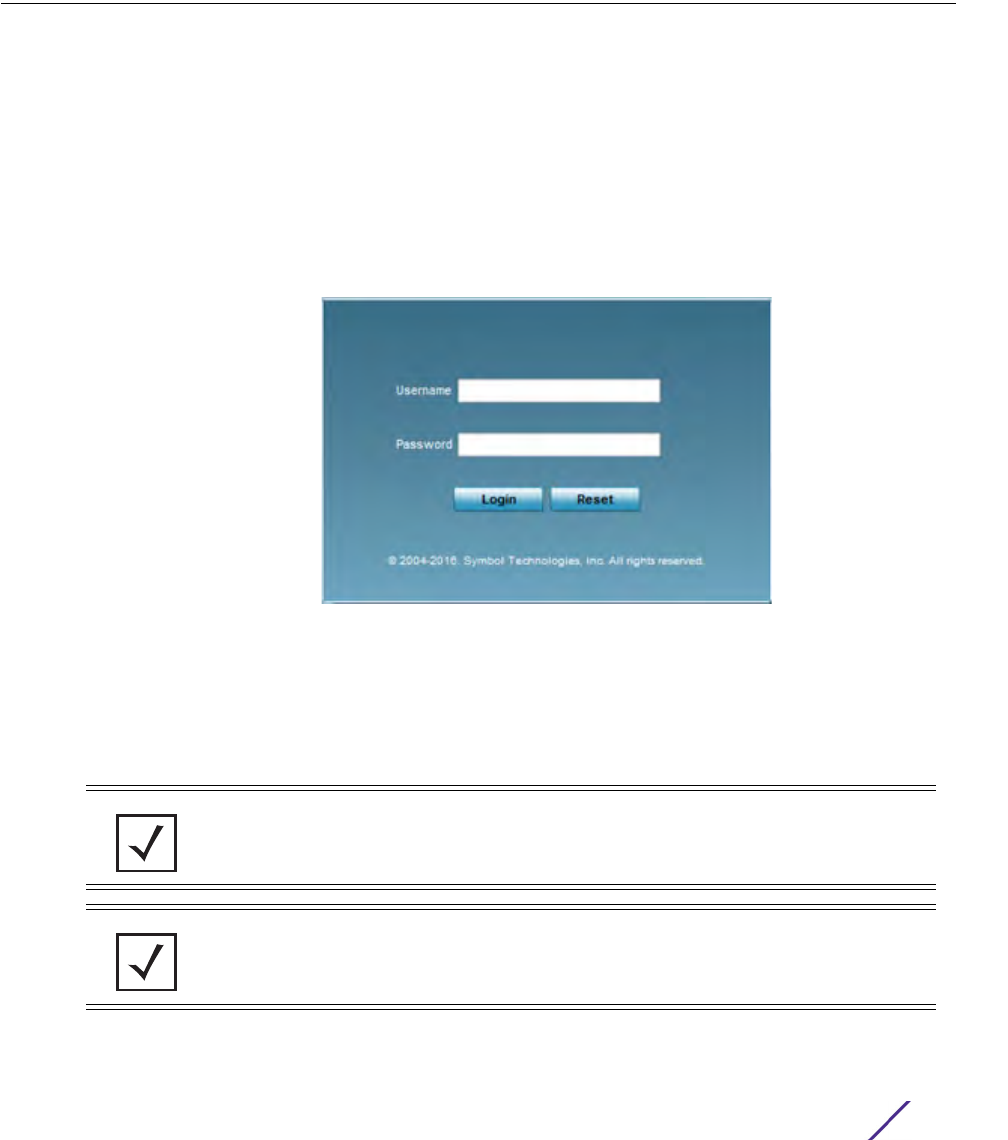
3 - 1
Wireless Controller and Service Platform System Reference Guide
3
Quick Start
WiNG controllers and service platforms utilize an initial setup wizard to streamline getting on the network
for the first time. This wizard configures location, network and WLAN settings and assists in the discovery
of Access Points and their connected clients.
3.1 Using the Initial Setup Wizard
Once deployed and powered on, complete the following to get the controller or service platform up and
running and access more advanced user interface functions:
1 Connect one end of an Ethernet cable to a port on the front of the controller or service platform, and
connect the other end to a computer with a working Web browser.
2 Set the computer to use an IP address between 192.168.0.10 and 192.168.0.250 on the connected port.
Set a subnet/network mask of 255.255.255.0.
3 Once the computer has an IP address, point the Web browser to: https://192.168.0.1/. The following login
screen displays.
Figure 3-1 Web UI Login Screen
4 Enter the default username admin in the Username field.
5 Enter the default password admin123 in the Password field.
6 Select the preferred language to display for the graphical user interface (GUI).
7 Select the Login button to load the management interface.
NOTE: When logging in for the first time, you are prompted to change the
password to enhance device security in subsequent logins.
NOTE: If you get disconnected when running the wizard, you can connect again
and resume the wizard setup.
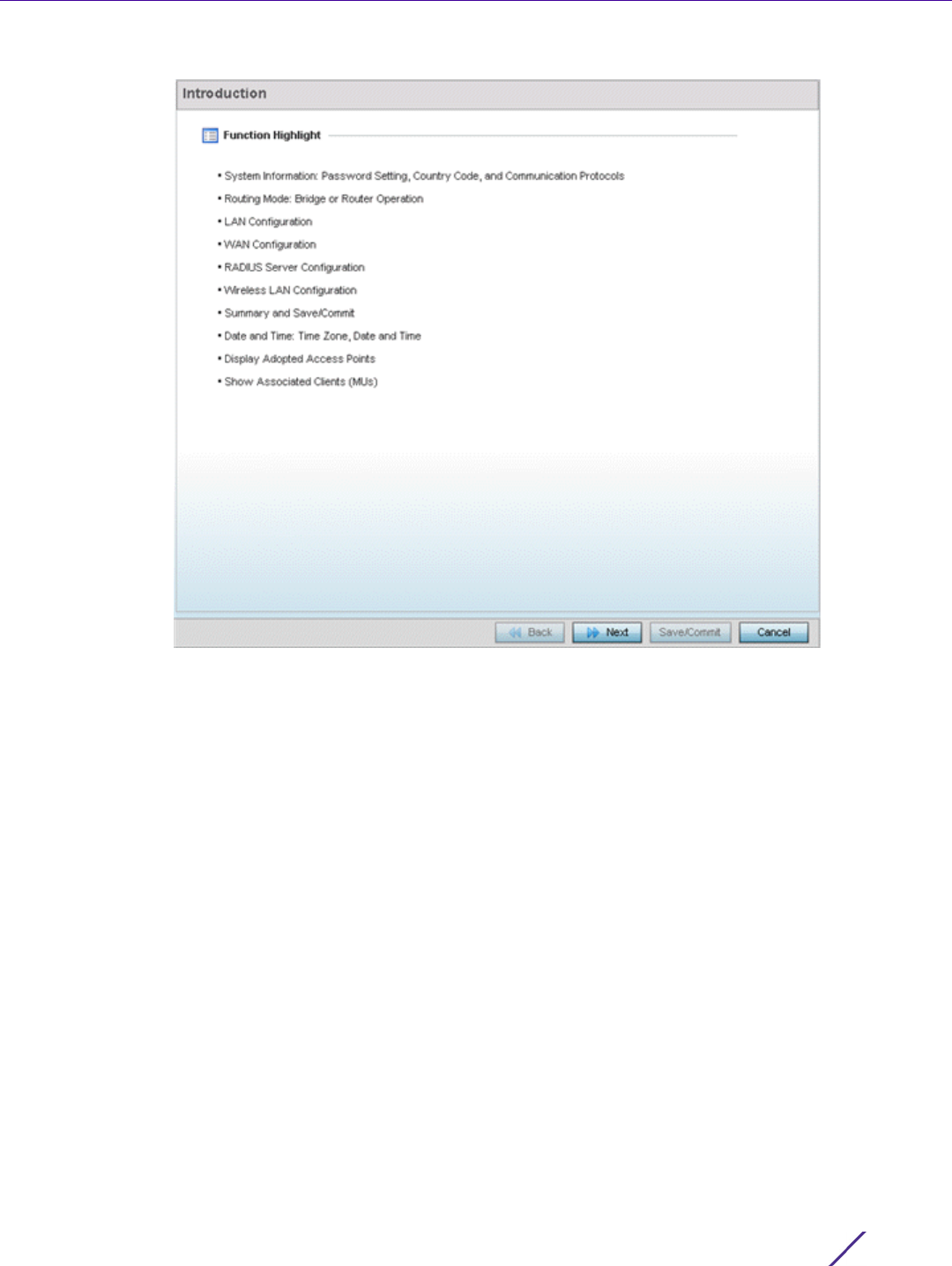
Quick Start
Wireless Controller and Service Platform System Reference Guide 3 - 2
Figure 3-2 Initial Setup Wizard - Introduction
The Introduction screen displays first (on the right-hand side of the screen), and lists the various actions
that can be performed using the setup wizard.
The wizard displays a Navigation Panel on the left-hand side of each screen to assist the administrator in
assessing which tasks still require completion before the controller or service-platform can be deployed.
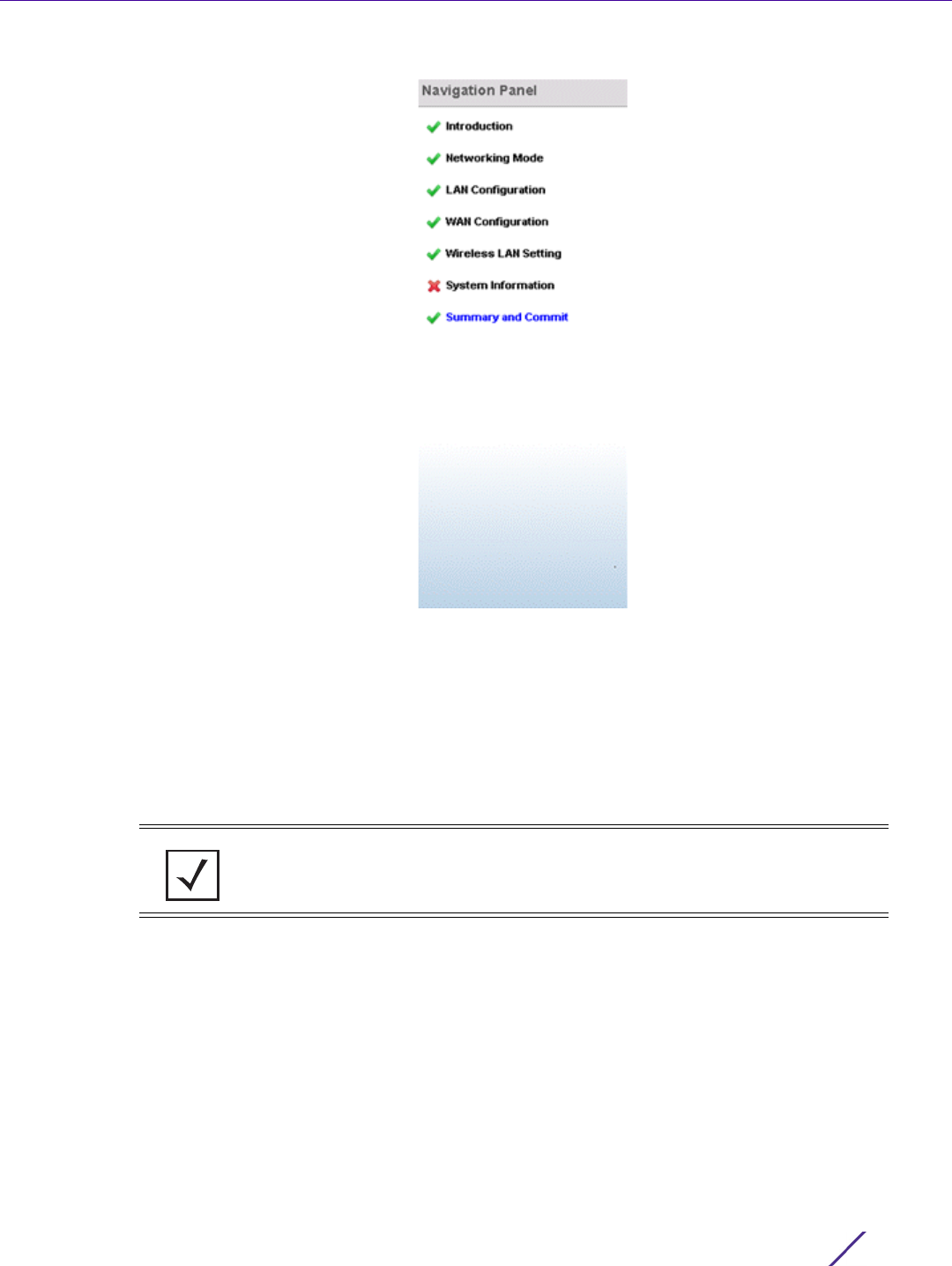
Quick Start
Wireless Controller and Service Platform System Reference Guide 3 - 3
Figure 3-3 Initial Setup Wizard - Navigation Panel
A green checkmark to the left of an item in the Navigation Panel defines the task as having its minimum
required configuration set correctly. A red X defines a task as still requiring at least one parameter be
defined correctly.
8Select Save/Commit within each page to save the updates made to that page's configuration.
9Select
Next to proceed to the next page listed in the Navigation Panel.
10 Select Back to revert to the previous screen in the Navigation Panel without saving your updates.
Selecting Cancel closes the wizard without committing any updates.
11 Select Next. The wizard displays the Networking Mode screen to define routing or bridging functionality.
NOTE: While you can scroll to any page in the Navigation Panel at any time, you
cannot complete the wizard until each task in the Navigation Panel has a green
checkmark displayed to the left of the task.
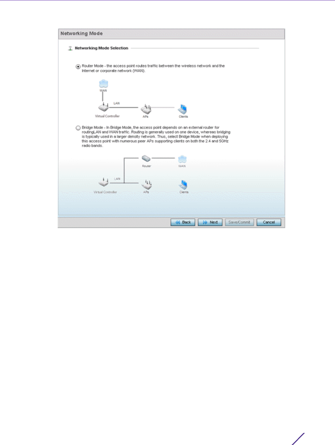
Quick Start
Wireless Controller and Service Platform System Reference Guide 3 - 4
Figure 3-4 Initial Setup Wizard - Networking Mode
12 Select one of the following network mode options:
•Router Mode - In Router Mode, connected Access Points route traffic between the local network
(LAN) and the Internet or external network (WAN). Router mode is recommended in a deployment
supported by just a single Access Point. When Router Mode is selected, an additional WAN screen
is available in wizard screen flow to configure interface settings for an Access Point’s WAN port.
•Bridge Mode - In Bridge Mode, connected Access Points depend on an external router for routing
LAN and WAN traffic. Routing is generally used on one device, whereas bridging is typically used in
a larger network. Thus, select Bridge Mode when deploying numerous peer Access Points
supporting clients on both the 2.4 and 5GHz radio bands.
13 Select Next. The wizard displays the LAN Configuration screen to set the LAN interface configuration.
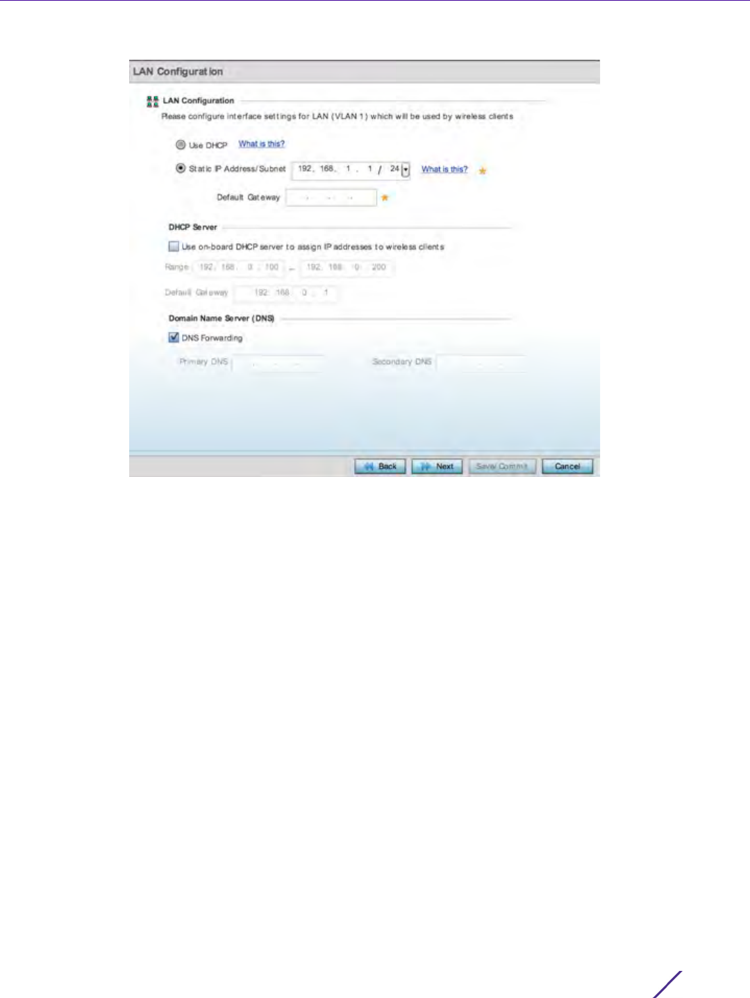
Quick Start
Wireless Controller and Service Platform System Reference Guide 3 - 5
Figure 3-5 Initial Setup Wizard - LAN Configuration
14 Set the following DHCP information for the LAN interface:
•Use DHCP - Select Use DHCP to enable an automatic network address configuration using local
DHCP server resources.
•Static IP Address/Subnet - Enter an IP Address and a subnet for the LAN interface. If Use DHCP is
selected, this field is not available. When selecting this option, define the following DHCP Server
and Domain Name Server (DNS) resources, as those fields are enabled on the bottom portion of
the screen.
-Use on-board DHCP server to assign IP addresses to wireless clients - Select this option to enable the
DHCP server to provide IP and DNS support to requesting clients on the LAN interface.
-Range - Enter a starting and ending IP Address range for client assignments on the LAN interface.
Avoid assigning IP addresses from x.x.x.1 - x.x.x.10 and x.x.x.255, as they are often reserved for
standard network services. This is a required parameter.
-Default Gateway - Define a default an address for use with the default gateway. This is a required
parameter.
•DNS Forwarding - Select this option to allow a DNS server to translate domain names into IP
addresses. If this option is not selected, a primary and secondary DNS resource must be specified.
DNS forwarding is useful when a request for a domain name is made but the DNS server,
responsible for converting the name into its corresponding IP address, cannot locate the matching
IP address.
- Primary DNS - Enter an IP Address for the main Domain Name Server providing DNS services for the
LAN interface.
- Secondary DNS - Enter an IP Address for the backup Domain Name Server providing DNS services for
the LAN interface.
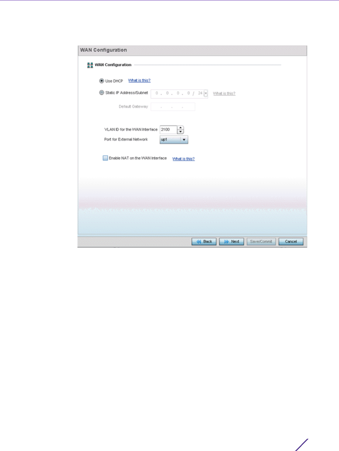
Quick Start
Wireless Controller and Service Platform System Reference Guide 3 - 6
15 Select Next. If Router was selected as the Access Point mode the wizard displays the WAN
Configuration screen. If Bridge was selected, the wizard proceeds to the Wireless LAN Setting screen.
Figure 3-6 Initial Setup Wizard - WAN Configuration
16 Set the following DHCP and Static IP Address/Subnet information to define how traffic is routed
between the local network (LAN) and the Internet or external network (WAN).
•Use DHCP - Select Use DHCP to enable an automatic network address configuration using local
DHCP server resources.
•Static IP Address/Subnet - Enter an IP Address/Subnet and gateway for the WAN interface. These
are required fields
-Default Gateway -Enter an IP Address for the default gateway on the WAN interface. If Use DHCP is
enabled, this field is not configurable.
-VLAN ID for the WAN Interface - Set the VLAN ID (virtual interface) to associate with the physical
WAN Interface. The default setting is VLAN 2100.
-Port for External Network - Select the physical port connected to the WAN interface. The list of
available ports varies based on the controller or service platform model.
-Enable NAT on the WAN Interface - Select the option to allow traffic to pass between WAN and LAN
interfaces.
17 Select Next. The wizard displays the Wireless LAN Setting screen to define up to four WLAN
configurations for the controller or service platform.
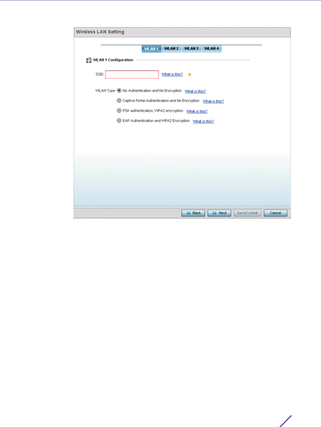
Quick Start
Wireless Controller and Service Platform System Reference Guide 3 - 7
Figure 3-7 Initial Setup Wizard - Wireless LAN Settings
18 Set the following parameters for up to four WLAN configurations:
•SSID - Enter or modify the Services Set Identification (SSID) associated with the WLAN. The WLAN
name is auto-generated using the SSID until changed by the administrator. The maximum number
of characters is 32. Do not use any of these characters (< > | " & \ ? ,).
•WLAN Type - Select a basic authentication and encryption scheme for the WLAN. Available options
include:
-No Authentication and No Encryption (provides no security at all)
-Captive Portal Authentication and No Encryption
-PSK authentication, WPA2 encryption
-EAP Authentication and WPA2 Encryption
19 Select Next. The wizard displays the System Information screen to set device deployment,
administrative contact and system time information. The system time can either be set manually or be
supplied by a dedicated Network Time Protocol (NTP) resource.
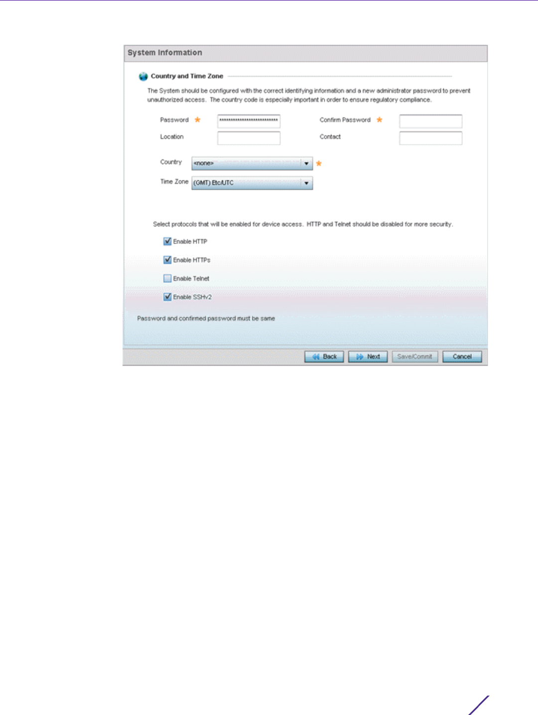
Quick Start
Wireless Controller and Service Platform System Reference Guide 3 - 8
Figure 3-8 Initial Setup Wizard - System Information
20 Refer to the Country and Time Zone field to set the following deployment information:
•Password - Enter and confirm a system password used to login into the controller or service
platform on subsequent login attempts.Changing the default system password is strongly
recommended to secure the proprietary configuration data maintained on the controller or service
platform.
•Location - Define the location of the controller or service platform deployment.
•Contact - Specify the contact information for the administrator. The credentials provided should
accurately reflect the individual responding to service queries.
•Country - Select the country where the controller or service platform is deployed. The controller or
service platform prompts for the correct country code on the first login. A warning message also
displays stating an incorrect country setting may result in illegal radio operation. Selecting the
correct country is central to legal operation. Each country has its own regulatory restrictions
concerning electromagnetic emissions and the maximum RF signal strength that can be
transmitted.
•Time Zone - Set the time zone where the controller or service platform is deployed. This is a
required parameter. The setting should be complimentary with the selected deployment country.
Refer to the Select protocols that will be enabled for device access area and enable those controller or
service platform interfaces for accessing the controller or service platform. HTTP and Telnet are considered
relatively insecure and only should be enabled is necessary.
21 Select Next. The wizard displays the Summary and Commit screen to summarize the screens (pages)
and settings updated using the wizard.
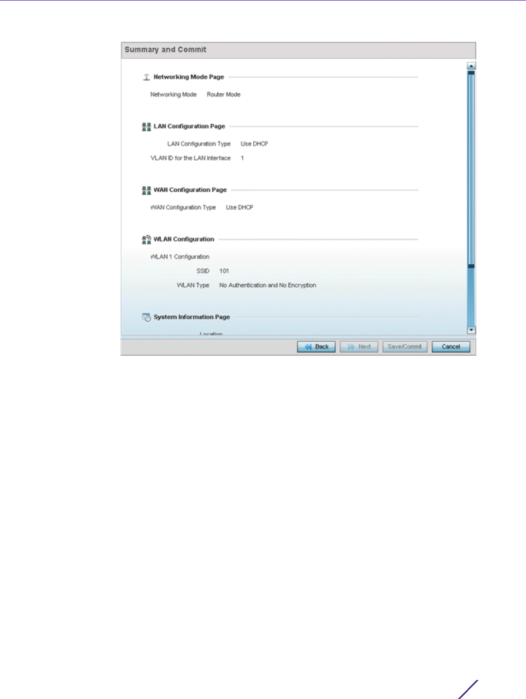
Quick Start
Wireless Controller and Service Platform System Reference Guide 3 - 9
Figure 3-9 Initial Setup Wizard - Summary and Commit
No user intervention or additional settings are required within this screen. Its an additional means of
validating the Access Point’s updated configuration before it’s deployed. However, if a screen displays
settings not intended as part of the initial configuration, the any screen can be selected again from within
the Navigation Panel and its settings modified accordingly.
22 If the configuration displays as intended, select Save/Commit to implement these settings to the
controller or service platform configuration. If additional changes are warranted based on the summary,
either select the target page from the Navigational Panel, or use the Back and Next buttons to scroll to
the target screen.

4 - 1
Wireless Controller and Service Platform System Reference Guide
4
Dashboard
The dashboard enables administrators to review and troubleshoot network device operation. Additionally, the
dashboard allows an administrative review of the network’s topology, an assessment of network’s component
health and a diagnostic review of device performance.
By default, the Dashboard displays the System screen, which is the top level in the device hierarchy. To view
information for Access Points, RF Domains or Controllers select the associated item in the tree.
For more information, refer to the following:
•Summary
•System Screen
•RF Domain Screen
•Controller
•Access Point Screen
•Network View
•Debug Wireless Clients
•Debug Captive Portal Clients
•Packet Capture
4.1 Summary
The Dashboard displays information organized by device association and inter-connectivity between the connected
Access Points and wireless clients.
1 To review dashboard information, select Dashboard.
2 Select
Summary if it’s not already selected by default.
The Dashboard displays the Health tab by default.

Dashboard
Wireless Controller and Service Platform System Reference Guide 4 - 2
Figure 4-1 System Dashboard screen - Health tab
4.1.1 Device Listing
Summary
The device menu displays information as a hierarchical tree, comprised of system, controller/service platform and
Access Point connection relationships.
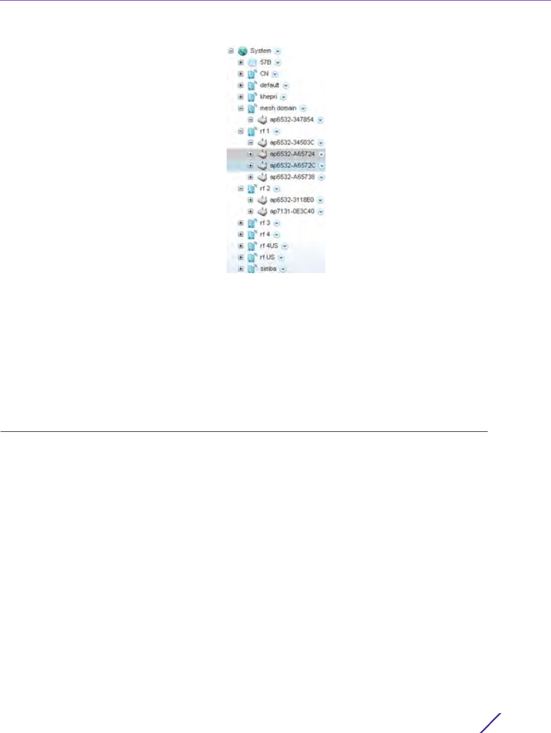
Dashboard
Wireless Controller and Service Platform System Reference Guide 4 - 3
Figure 4-2 Dashboard Menu Tree
The Search option, at the bottom of the screen, enables you to filter (search amongst) RF Domains. The By drop-
down menu refines the search. You can further refine a search using the following:
•Auto – The search is automatically set to device type.
•Name – The search is performed for the device name specified in the Search text box.
•WLAN – The search is performed for the WLAN specified in the Search text box.
•IP Address – The search is performed for the IP Address specified in the Search text box.
•MAC Address – The search is performed for the MAC Address specified in the Search text box.
4.2 System Screen
The System screen displays system-wide network status. The screen is partitioned into the following tabs:
•Health – The Health tab displays information about the state of the WiNG device managed system.
•Inventory – The Inventory tab displays information on the physical devices managed within the WiNG
wireless network.
4.2.1 Health
Health
The Health tab displays device performance status for managed devices, and includes their RF Domain
memberships.
To assess system health:
1Select
Dashboard.
2Select
Summary if it’s not already selected by default.
3Select
System. The Health tab displays by default.
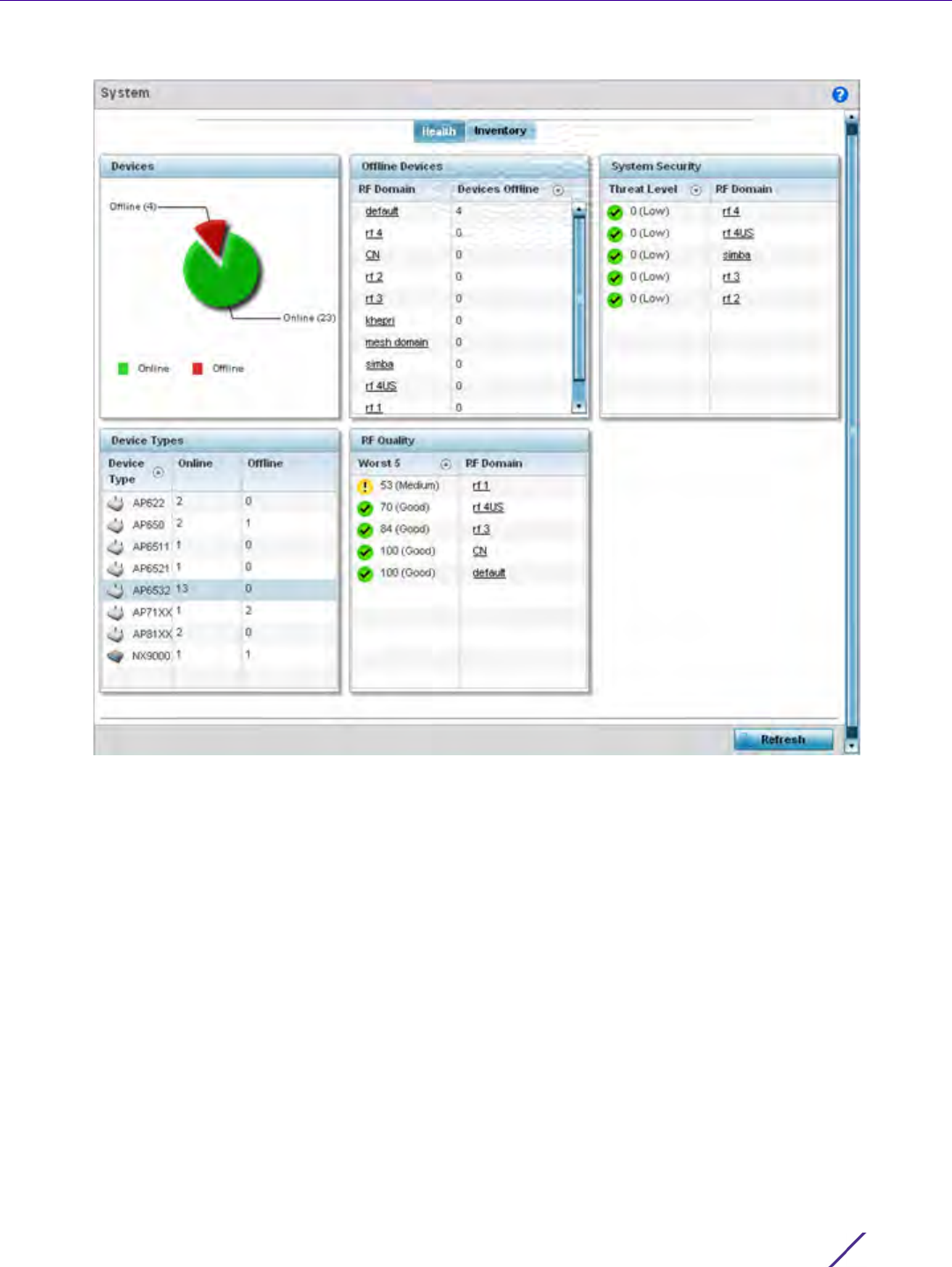
Dashboard
Wireless Controller and Service Platform System Reference Guide 4 - 4
Figure 4-3 System Dashboard screen - Health tab
The Health screen is partitioned into the following fields:
•The
Devices field displays a ratio of offline versus online devices within the system. The information is
displayed in pie chart format to illustrate device support ratios.
•The
Device Type field displays a numerical representation of the different controller, service platform and
Access Point models in the current system. Their online and offline device connections are also displayed.
Does this device distribution adequately support the number and types of Access Point radios and their
client load requirements.
•The
Offline Devices field displays a table of supported RF Domains within the system, with each RF Domain
listing the number offline devices within that RF Domain. Listed RF Domains display as individual links that
can be selected to RF Domain information in greater detail.
•The
RF Quality Index displays RF quality per RF Domain. It's a measure of the overall effectiveness of the RF
environment displayed in percentage. It's a function of the connect rate in both directions, retry rate and
error rate.
The RF Quality field displays an average quality index supporting each RF Domain. The table lists the bottom
five (5) RF quality values for RF Domains. Listed RF Domains display as individual links that can be selected to
RF Domain information in greater detail. Use this diagnostic information to determine what measures can be
taken to improve radio performance in respect to wireless client load and the radio bands supported.
The quality is measured as:
•0-20 – Very poor quality

Dashboard
Wireless Controller and Service Platform System Reference Guide 4 - 5
•20-40 – Poor quality
•40-60 – Average quality
• 60-100 – Good quality
The System Security field displays RF intrusion prevention stats and their associated threat level. The greater
the number of unauthorized devices, the greater the associated threat level. The System Security field displays
a list of up to five RF Domains in relation to the number of associated wireless clients. The RF Domains appear
as links that can be selected to display RF Domain information in greater detail.
4.2.2 Inventory
System Screen
The system screen’s Inventory tab displays granular data on specific devices supported within the network. The
screen provides a complete overview of the number and state WiNG managed devices. Information is displayed in
easy to read tables and graphs. This screen also provides links for more detailed information.
To assess the system inventory:
1Select
Dashboard.
2Select
Summary if it’s not already selected by default.
3Select
System.
4 Select the Inventory tab.
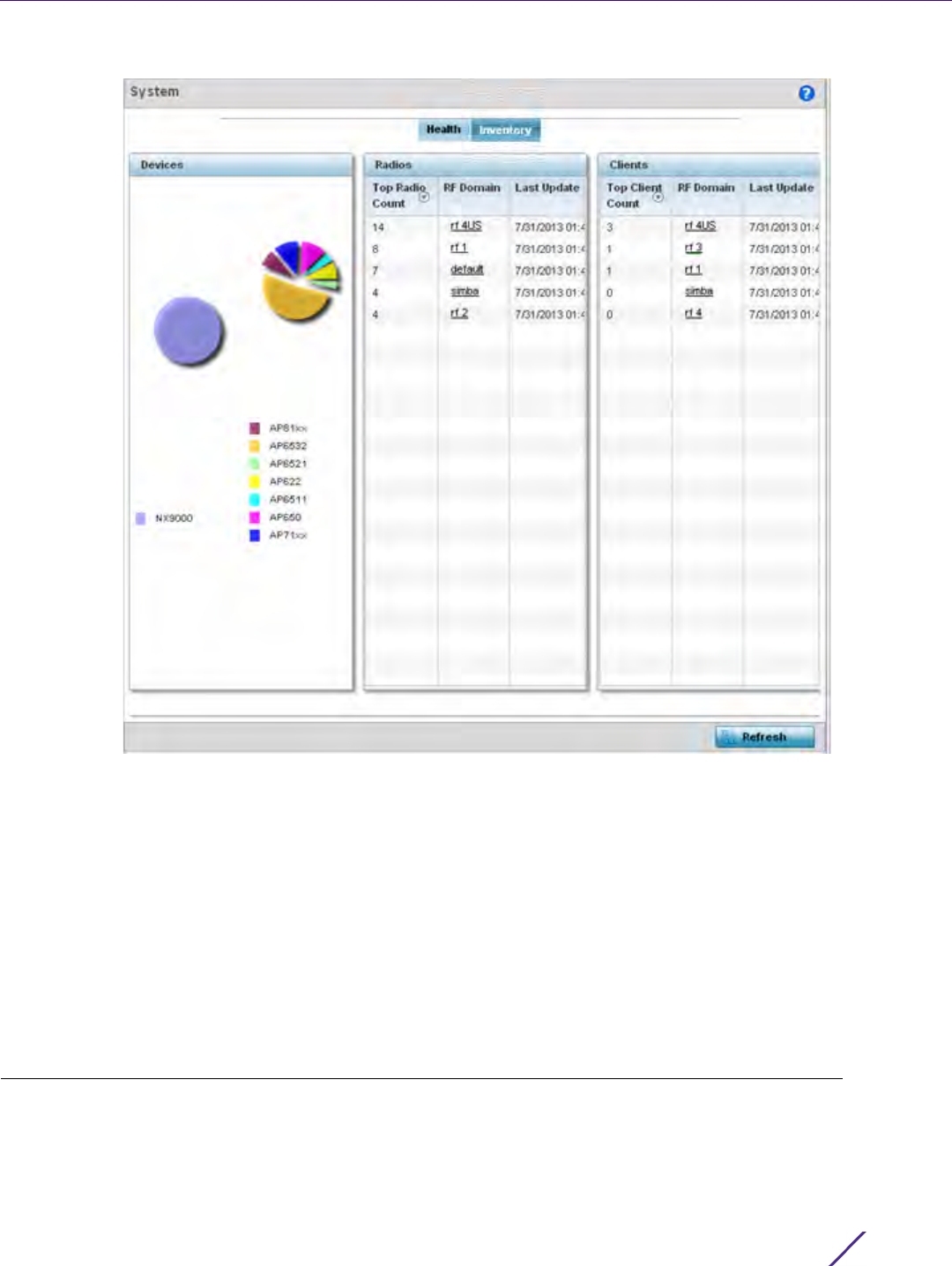
Dashboard
Wireless Controller and Service Platform System Reference Guide 4 - 6
Figure 4-4 System screen - Inventory tab
The information within the Inventory tab is partitioned into the following fields:
•The
Devices field displays a ratio of peer controllers and service platforms as well as their managed Access
Point radios. The information is displayed in pie chart format. The Device Type field displays a numerical
representation of the different controller models and connected Access Points in the current system.
•The
Radios field displays top performing radios, their RF Domain memberships and a status time stamp. RF
Domain information can be selected to review RF Domain membership information in greater detail.
Information in the Radio area is presented in two tables. The first lists the total number of Radios managed
by this system, the second lists the top five RF Domains in terms of the number of available radios.
•The wireless
Clients field lists the top five RF Domains with the highest total number of clients managed by
connected devices in this system. RF Domain information can be selected to review RF Domain membership
information in greater detail. Select Refresh to update the screen to its latest values.
4.3 RF Domain Screen
RF Domains allow administrators to assign configuration data to multiple devices deployed in a common coverage
area, such as in a floor, building or site. Each RF Domain contains policies that can determine a Smart RF or WIPS
configuration.RF Domains enable administrators to override WLAN SSID name and VLAN assignments. This
enables the deployment of a global WLAN across multiple sites and unique SSID name or VLAN assignments to

Dashboard
Wireless Controller and Service Platform System Reference Guide 4 - 7
groups of Access Points servicing the global WLAN. This WLAN override technique eliminates the requirement for
defining and managing a large number of individual WLANs and profiles.
A configuration contains (at a minimum) one default RF Domain and can optionally use additional user defined RF
Domains:
• Default RF Domain - Automatically assigned to each controller or service platform and associated Access
Point by default.
• User Defined RF Domains - Created by administrators and manually assigned to individual controller or
service platforms, but can be automatically assigned to Access Points using adoption policies.
Each controller and service platform is assigned to only one RF Domain at a time. However, a user defined RF
Domain can be assigned to multiple controllers or service platforms as required. User defined RF Domains can be
manually assigned or automatically assigned to Access Points using an AP provisioning policy.
The RF Domain screen displays system-wide network status. The screen is partitioned into the following tabs:
•RF Domain Health – The Health tab displays information about the state of the RF Domain and network
performance as tallied from its collective device members.
•RF Domain Inventory – The Inventory tab displays information on the physical devices comprising the RF
Domain.
4.3.1 RF Domain Health
The Health tab displays the status of the RF Domain’s device membership.
To assess the RF Domain health:
1Select
Dashboard.
2Select
Summary if it’s not already selected by default.
3Expand the
System node to display RF Domains.
4Select a RF Domain. The Health tab displays by default.
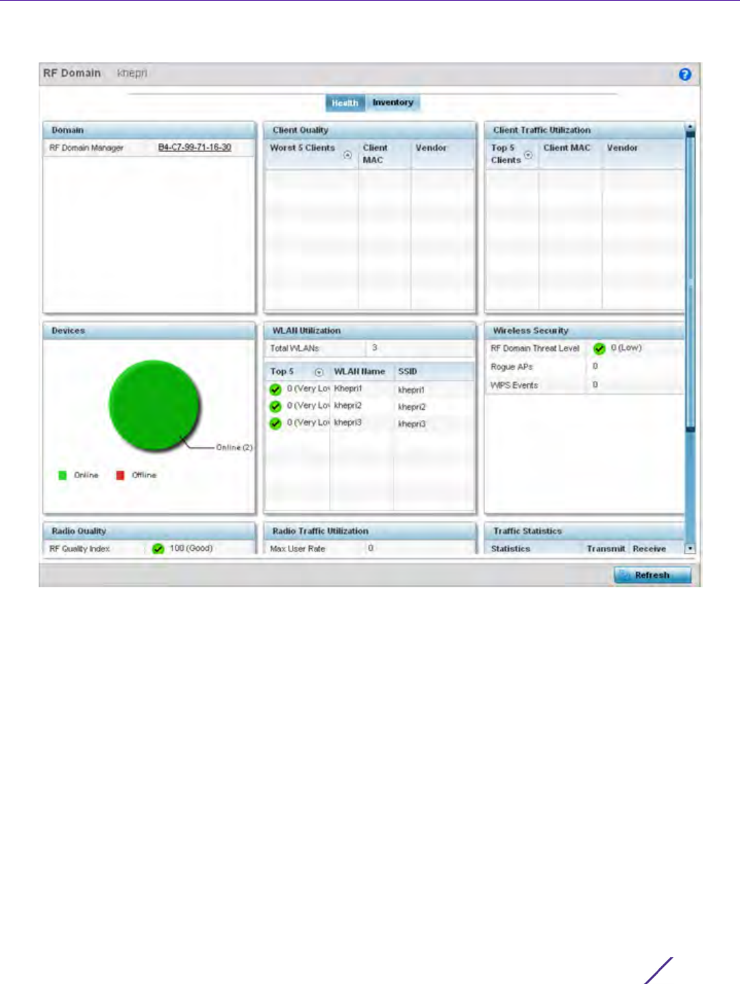
Dashboard
Wireless Controller and Service Platform System Reference Guide 4 - 8
Figure 4-5 RF Domain screen - Health tab
Refer to the following RF Domain health information for member devices:
•The
Domain field lists the RF Domain manager reporting utilization statistics. The MAC address displays as a
link that can be selected to display RF Domain information in at more granular level. A RF Domain manager
can retain and store new firmware images for RF Domain member Access Points.
•The
Devices field displays the total number of devices and the status of the devices in the network as a
graph. This area displays the total device count managed by this device and their status (online vs. offline) as
a pie graph.
•The
Radio Quality table displays a table of RF quality on a per radio basis. It is a measure of the overall
effectiveness of the RF environment displayed in percentage. It is a function of the transmit retry rate in
both directions and the error rate. This area of the screen displays the average quality index across all the
defined RF Domain on the wireless controller. The table lists worst five of the RF quality values of all the
radios defined on the wireless controller. The quality is measured as:
-0-20 - Very poor quality
- 20-40 - Poor quality
-40-60 - Average quality
- 60-100 - Good quality
5Select a Radio Id to view all the statistics for the selected radio in detail.

Dashboard
Wireless Controller and Service Platform System Reference Guide 4 - 9
• The Client Quality table displays RF quality for the worst five performing clients.It is a function of the transmit
retry rate in both directions and the error rate. This area of the screen displays the average quality index across
all the defined RF Domain on the wireless controller. The quality is measured as:
•0-20 - Very poor quality
• 20-40 - Poor quality
•40-60 - Average quality
• 60-100 - Good quality
6 Select a client to view its statistics in greater detail.
•WLAN Utilization displays how efficiently the WLANs are used. Traffic utilization is defined as the
percentage of current throughput relative to the maximum possible throughput for the WLAN. The total
number of WLANs is displayed above the table. The table displays a list of the top five WLANs in terms of
overall traffic utilization. It displays the utilization level names, WLAN name and SSIDs for each of the top
five WLANs.
•Radio Traffic Utilization displays how efficiently the RF medium is used. Traffic utilization is defined as the
percentage of current throughput relative to the maximum possible throughput for the RF Domain. The
Traffic Index area displays an overall quality level for radio traffic and the Max User Rate displays the
maximum data rate of associated radios. The table displays a list of the top five radios in terms of overall
traffic utilization quality. It displays the radio names, MAC Addresses and radio types for each of the top five
radios.
•Client Traffic Utilization displays how efficiently the RF medium is utilized for connected clients. Traffic
utilization is defined as the percentage of current throughput relative to the maximum possible throughput
for the clients in the RF Domain. The table displays a list of the top five performing clients in respect to
overall traffic utilization. It displays the client names, MAC Addresses and vendor for each of the top five
clients.
•Wireless Security displays the overall threat index for the system. This index is based on the number of
Rogue/Unsanctioned APs and Wireless Intrusion Protection System (WIPS) events detected. The index is in
the range 0 - 5 where 0 indicates there are no detected threats. An index of 5 indicates a large number of
intrusion detection events or rogue/unsanctioned APs detected.
•Traffic Statistics include transmit and receive values for Total Bytes, Total Packets, User Data Rate,
Broadcast/Multicast Packets, Management Packets, Tx Dropped Packets and Rx Errors.
4.3.2 RF Domain Inventory
Refer to the following RF Domain inventory data collected by member controllers, service platforms or Access
Points:
To review the RF Domain inventory:
1Select
Dashboard.
2Select
Summary if it’s not already selected by default.
3Expand the
System node to display RF Domains.
4Select a RF Domain.
5 Select the Inventory tab.
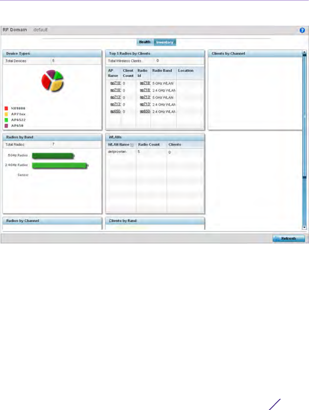
Dashboard
Wireless Controller and Service Platform System Reference Guide 4 - 10
Figure 4-6 RF Domain screen - Inventory tab
•The Inventory tab displays information on the devices managed by RF Domain member devices in the
controller, service platform or Access Point managed network. The Inventory screen enables an administrator
to overview of the number and state of the devices in the selected RF Domain. Information is displayed in
easy to read tables and graphs.
•The
Device Types table displays the devices types populating the RF Domain. The Device Type area displays
an exploded pie chart that displays the type of device and their numbers in the RF Domain.
•The
Radios by Band table displays a bar graph of RF Domain member device radios classified by their radio
band or sensor dedication. Review this information to assess whether RF Domain member radios adequately
support client device traffic requirements.
•The
Radios by Channel table displays pie charts of the different channels utilized by RF Domain member
radios. These dedicated channels should be as segregated as possible from one another to avoid
interference. If too many radios are utilizing a single channel, consider off-loading radios to non utilized
channels to improve RF Domain performance.
•The
Top 5 Radios by Clients table displays a list of radios with the highest number of clients. This list displays
the radio IDs as links that can be selected to display individual radio information in greater detail.
•The
WLANs table displays a list of WLANs utilized by RF Domain member devices. The table is ordered by
WLAN member device radio count and their number of connected clients. Use this information to assess
whether the WLAN is overly populated by radios and clients contributing to congestion.
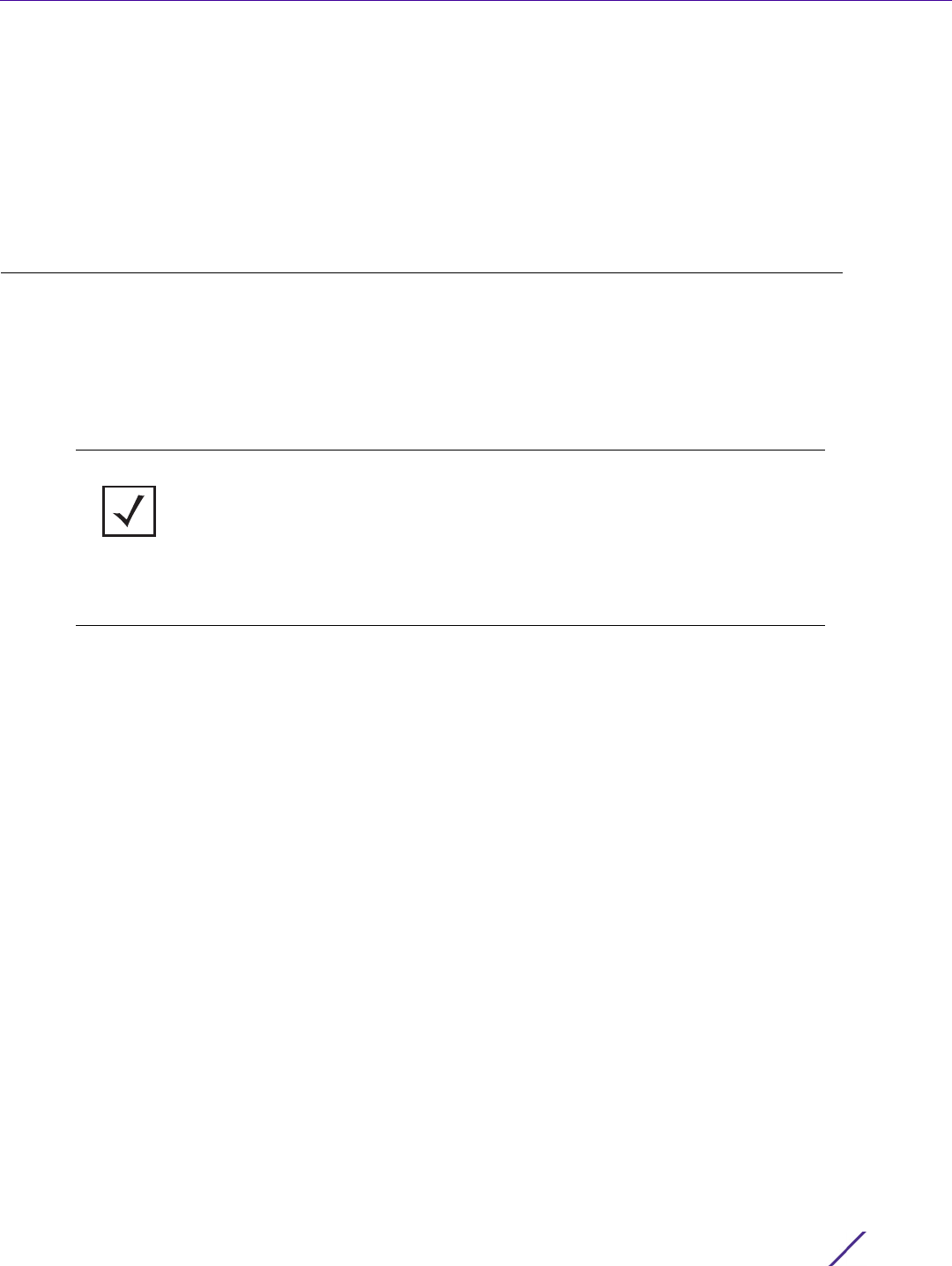
Dashboard
Wireless Controller and Service Platform System Reference Guide 4 - 11
•The
Clients by Band table displays the radio band utilization of connected RF Domain member clients.
Assess whether the client band utilization adequately supports the intended radio deployment objectives of
the connected RF Domain member Access Point radios.
•The
Clients of Channel table displays a bar-graph of wireless clients classified by their frequency. Information
for each channel is further classified by their 802.11x band. In the 5GHz channel, information is displayed
classified under 802.11a and 802.11an bands. In the 2.4 GHz channel, information is displayed classified under
802.11b, 802.11bg, and 802.11bgn band.
4.4 Controller
The Wireless Controller screen displays system collected network status for controllers and service platforms. The
screen is partitioned into two tabs:
•Controller Health – The Health tab displays information about the state of the controller or service platform
managed wireless network.
•Controller Inventory – The Inventory tab displays information on the physical devices managed by the
controller or service platform.
4.4.1 Controller Health
To assess the controller or service platform’s network health:
1Select
Dashboard.
2Select
Summary if it’s not already selected by default.
3Expand the
System node to display RF Domains.
4 Select and expand a RF Domain to expose its member controllers or service platforms.
5 Select a controller or service platform. The Health tab display by default.
NOTE: A T5 controller can also be selected from the dashboard’s controller level to
display a set of unique T5 dashboard screens. A T5 controller uses a different
operating system to manage its connected radio devices, as opposed to the WiNG
operating used by RFS controllers and NX service platforms. However, a T5
controller, once enabled as a supported external device, can provide data to WiNG
to assist in a T5’s management within a WiNG supported subnet populated by both
types of devices. For information on enabling controller adoption of external
devices (for T5 support specifically) refer to, Adoption Overrides (Controllers
Only) on page 5-48.
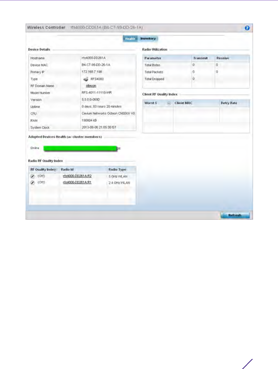
Dashboard
Wireless Controller and Service Platform System Reference Guide 4 - 12
Figure 4-7 Wireless Controller screen - Health tab
Refer to the Device Details table for information about the selected controller or service platform The following
information is displayed:
•Hostname - Lists the administrator assigned name of the controller or service platform.
•Device MAC - Lists the factory encoded MAC address of the controller or service platform.
•Type - Indicates the type of controller or service platform. An icon representing the RFS controller or NX
service platform device type is displayed along with the model number.
•RF Domain Name - Lists the RF Domain to which the controller or service platform belongs. The RF Domain
displays as a link that’s selectable to display RF Domain data in greater detail.
•Model Number - Lists the model number and hardware SKU information of the selected controller or service
platform to refine its intended deployment region.
•Version - Lists the firmware version currently running on the controller or service platform. Compare this
version against the version currently on the support site to ensure the controller or service platform has the
latest feature set available.
•Uptime - Displays the duration the controller or service platform has been running since it was last restarted.
•CPU - Displays the CPU installed on this controller or service platform.
•RAM - Displays the amount of RAM available for use in this system.
•System Clock - Displays the current time set on the controller or service platform.

Dashboard
Wireless Controller and Service Platform System Reference Guide 4 - 13
The Adopted Devices Health (w/ cluster members) displays a graph of Access Points in the system with the
available Access Points in green and unavailable Access Points in red.
The Radio RF Quality Index provides a table of RF quality on a per radio basis. It is a measure of the overall
effectiveness of the RF environment displayed in percentage. It is a function of the connect rate in both
directions, the retry rate and the error rate. The screen displays the average quality index within the Access
Point single radio. The table lists bottom five (5) of the RF quality values by Access Point radio. The quality is
measured as:
•0-20 - Very poor quality
•20-40 - Poor quality
•40-60 - Average quality
• 60-100 - Good quality
6 Select a radio Id to view statistics in greater detail.
The Radio Utilization table displays how efficiently the RF medium is used. Radio utilization is defined as the
percentage of current throughput relative to the maximum possible throughput for the radio. The Radio
Utilization table displays the Access Point radios in terms of the number of associated wireless clients and the
percentage of utilization. It also displays a table of packets types transmitted and received.
The Client RF Quality Index displays a table of RF quality on a per client basis. It is a measure of the overall
effectiveness of the RF environment displayed in percentage. It is a function of the connect rate in both
directions, the retry rate and the error rate. This area of the screen displays the average quality index for a
client. The table lists bottom five (5) of the RF quality values by a client. Quality is measured as:
•0-20 - Very poor quality
•20-40 - Poor quality
•40-60 - Average quality
• 60-100 - Good quality
7 Select a client MAC to view all the statistics for the selected client in greater detail.
4.4.2 Controller Inventory
The Inventory tab displays information for the devices managed by the system. This screen enables a system
administrator to have a complete overview of the number and state of managed devices. Information is displayed
in easy to read tables and graphs. The Inventory screen also provides links for the system administrator to get
more detailed information.
To assess the controller or service platform inventory:
1Select
Dashboard.
2Select
Summary if it’s not already selected by default.
3Expand the
System node to display RF Domains.
4 Select and expand a RF Domain to expose its member controllers or service platforms.
5 Select a controller or service platform.
6 Select the Inventory tab.
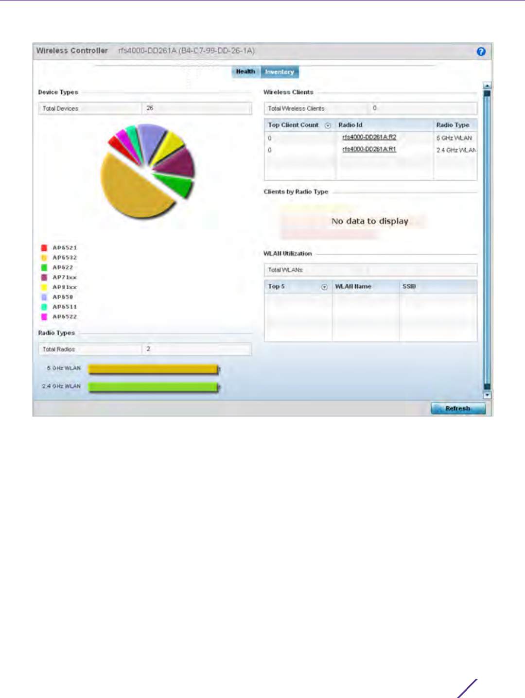
Dashboard
Wireless Controller and Service Platform System Reference Guide 4 - 14
Figure 4-8 Wireless Controller screen - Inventory tab
The Inventory tab displays information on the devices managed by the controller or service platform. The
Inventory screen enables an administrator to overview of the number and state of controller or service platform
managed devices and their utilization. Refer to the following Inventory data:
•The
Device Types field displays a ratio of devices managed by this controller or service platform in pie chart
format. The Device Type area displays an exploded pie chart that displays the type of device and their
numbers in the current system.
•The
Radios Type field displays the total number of radios managed by this controller or service platform. The
graph lists the number of radios in both the 2.4 GHz and 5 GHz radio bands.
•The
Wireless Clients table lists clients managed by this controller or service platform by connected client
count. Information is presented in two (2) tables and a graph. The first table lists the total number of clients
managed by the listed controller or service platform. The second lists the top five (5) radios in terms of the
number of connected clients. The graph just below the table lists the number of clients by radio type.
•The
WLAN Utilization table displays utilization statistics for controller or service platform WLAN
configurations. Information displays in two tables. The first table lists the total number of WLANs managed
by this system. The second table lists the top five (5) WLANs in terms of the usage percentage along with
the name and network identifying SSID.
Dashboard
Wireless Controller and Service Platform System Reference Guide 4 - 15
4.4.3 T5 Controller Dashboard
A T5 controller can be selected from the dashboard’s controller level to display a set of unique T5 dashboard
screens. A T5 controller uses a different operating system to manage its connected radio devices, as opposed to
the WiNG operating used by RFS controllers and NX service platforms. However, a T5 controller, once enabled as a
supported external device, can provide data to WiNG to assist in a T5’s management within a WiNG supported
subnet populated by both types of devices.
To review a T5’s controller dashboard:
1Select
Dashboard.
2Select
Summary if it’s not already selected by default.
3Expand the
System node to display RF Domains.
4 Select and expand a RF Domain to expose its member controllers or service platforms.
5 Select a T5 controller from amongst the devices listed at the dashboard’s controller level. T5 devices will not
appear at any other level in the dashboard’s device tree.
Figure 4-9 T5 Dashboard tab
6 Refer to the following T5 specific dashboard stats to assess whether a CPE’s DLS connection is problematic and
has excessive device rests (rendering the T5 device temporarily offline).
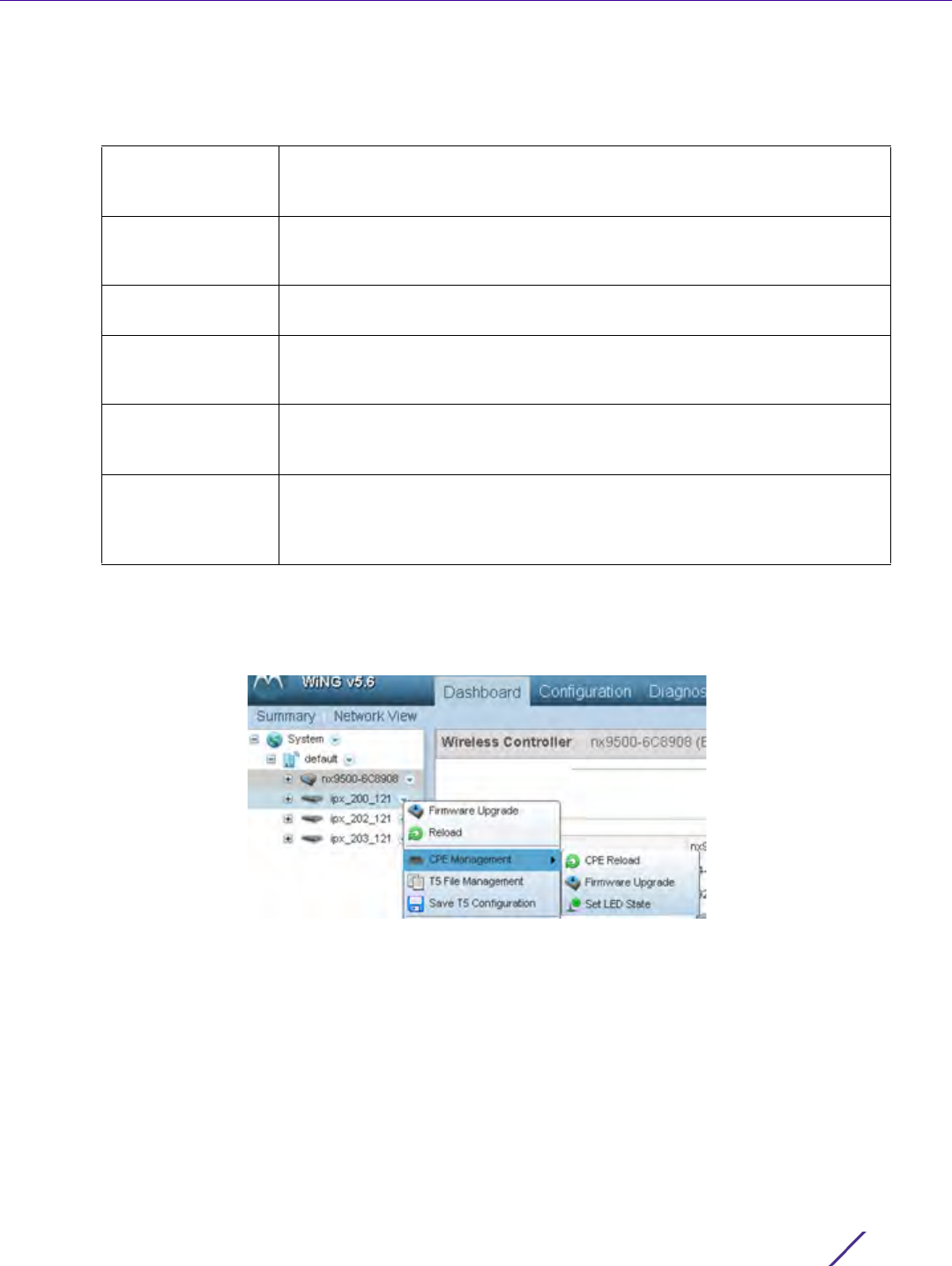
Dashboard
Wireless Controller and Service Platform System Reference Guide 4 - 16
The Customer Premises Equipment (CPEs) are the T5 managed radio devices. These CPEs use Digital
Subscriber Line (DSL) as their high speed Internet access mechanism using the CPE’s physical wallplate
connection and phone jack.
7 Select a T5 device from amongst the devices listed in the dashboard’s controller level, and right click the arrow
to the right to list an additional menu of diagnostic activities that can be administrated for the selected T5
device.
Figure 4-10 T5 Dashboard Menu Path
Use these additional T5 configuration items to optionally upgrade T5 managed device firmware, reload
configurations, upgrade the T5 CPE and manage T5 managed device LED status.
8Select
Firmware Upgrade to conduct firmware updates for T5 managed devices.
DSL Average
Response Time
Lists each CPE’s DSL name and its average response time in microseconds.
Use this data to assess whether a specific DSL is experiencing response
latency negatively impacting performance.
DSL Downstream
Coding Violations
Displays each listed DSL’s number of coding violations as a measure of
erroneous data degrading the DSL’s performance within the T5’s network
coverage area.
DSL Utilization Lists each CPE’s DSL name and its transmit utilization by percentage of
overall load.
DSL Downstream
Severely Eroded
Seconds
Displays each listed DSL’s eroded seconds, as a negative measure of
delivery latency degrading the DSL’s performance within the T5’s network
coverage area.
DSL Status Lists the name of the DSL utilized on T5 managed CPE devices, and their
downstream (transmit) data rate (in Mbps) and downstream throughput
margin (in dB).
CPE Reset The a selected CPE’s number of resets. A reset renders the CPE offline until
completed, and consequently should be carefully tracked to ensure
consistent online availability amongst CPEs in the same radio coverage
area.
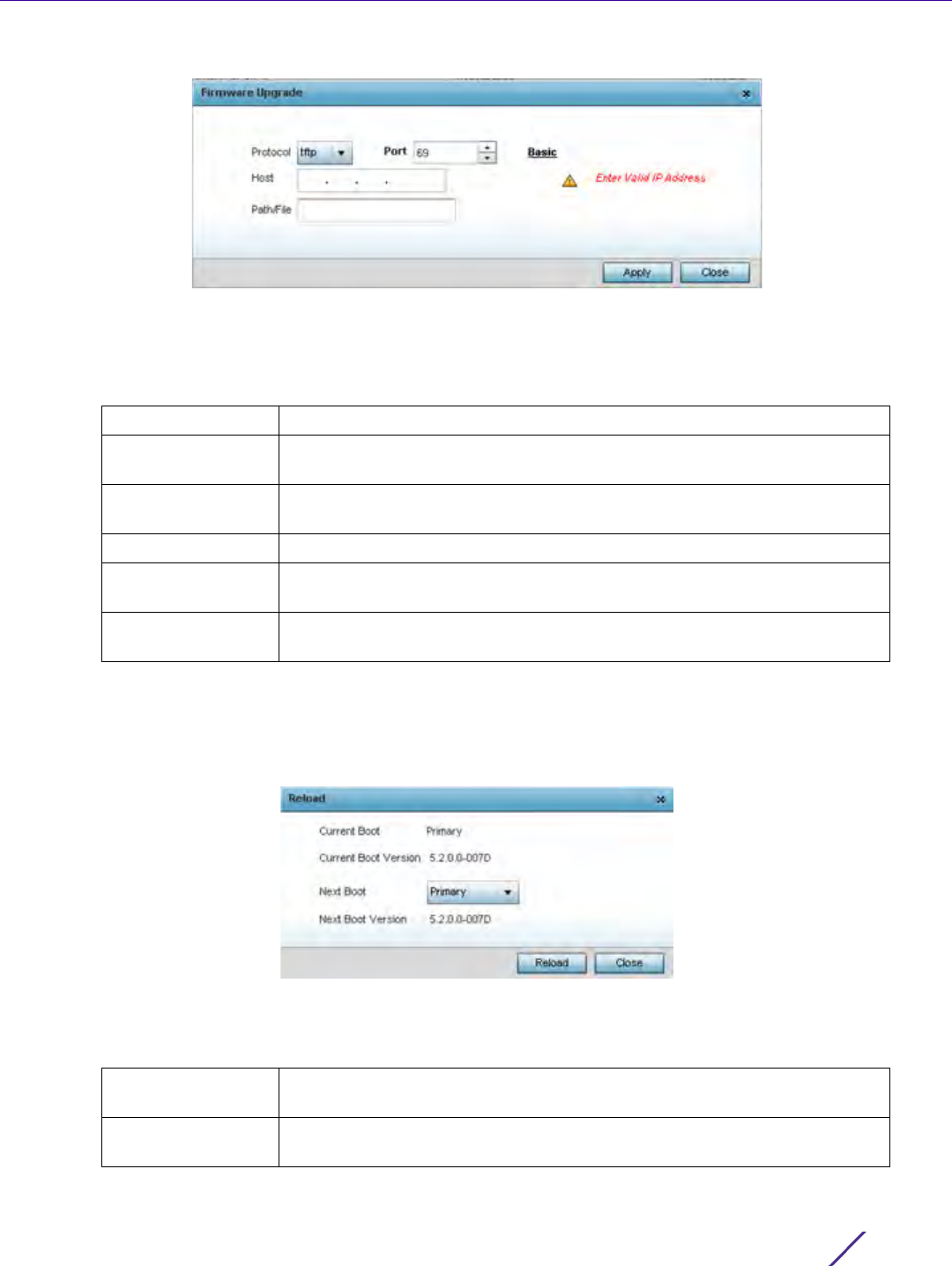
Dashboard
Wireless Controller and Service Platform System Reference Guide 4 - 17
Figure 4-11 T5 Dashboard Firmware Upgrade
By default, the Firmware Upgrade screen displays the tftp server parameters for the target T5 device firmware
file.
9 Provide the following information to accurately define the location of the T5 device firmware file.
10 Select Apply to save the T5 device firmware connection protocol settings. Select Close to exit the Firmware
Upgrade popup.
11 Select Reload to administrate current and next boot version available to the selected T5 device.
Figure 4-12 T5 Dashboard Device Reload
12 Review the following Current and Next Boot Versions and optionally apply a primary or secondary designation
to the next boot version used in pending T5 managed device updates:
Protocol Select the FTP or TFTP protocol used for updating T5 device firmware.
Port Use the spinner control, or manually set, the T5 device port used by the
selected transfer protocol for firmware updates.
Host Provide the numeric IP address of the resource used to update the
firmware.
User Name Define the user name used to access either a FTP or TFTP resource.
Password Specify the password for the user account to access a FTP or a TFTP
resource.
Path/File Specify the correct directory path to the firmware file. Enter the complete
relative path to the file on the server.
Current Boot Lists whether the firmware image for a current T5 managed device boot is
the primary or secondary firmware image.
Current Boot
Version
Lists the firmware version currently utilized with T5 managed device boots.
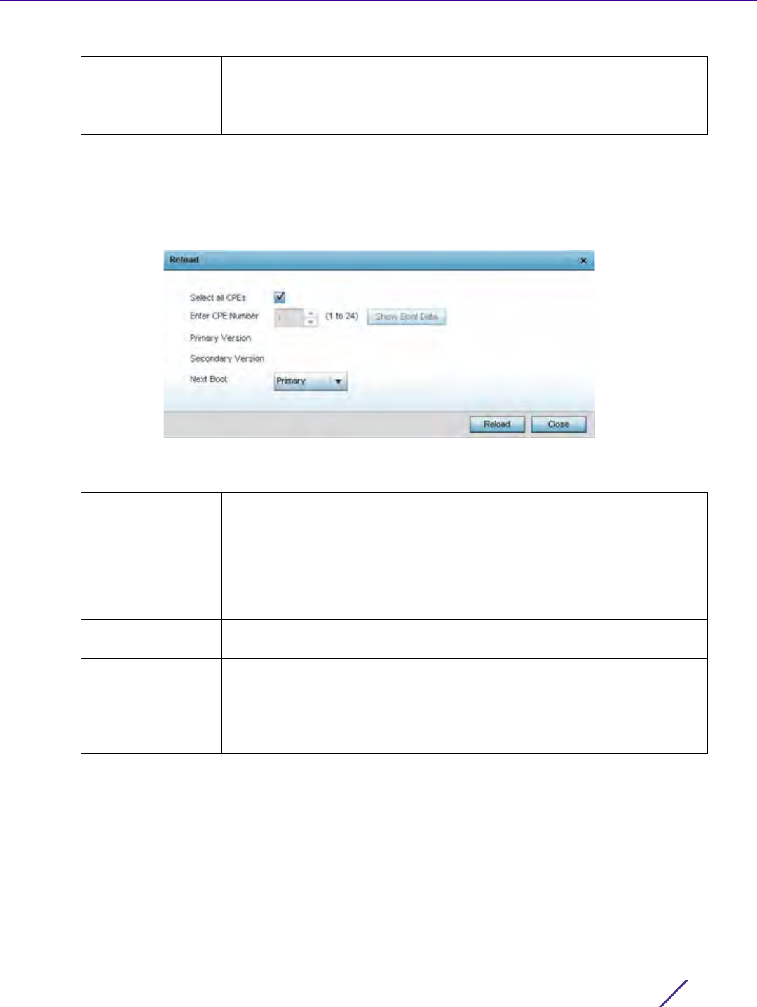
Dashboard
Wireless Controller and Service Platform System Reference Guide 4 - 18
13 Select Reload to apply the current and next boot settings to a T5 update. Select Close to exit the Reload
popup.
14 Expand the CPE Management item from the T5 dashboard and select CPE Reload. Customer Premises
Equipment (CPE) are the T5 managed radio devices.
Figure 4-13 T5 Dashboard CPE Management Reload
15 Use the Reload screen to specify the CPEs to target for a T5 managed device firmware upgrade.
16 Select Reload to make available the selected firmware images(s) to the T5 in advance of initiating device
upgrades. Select Close to exit the Reload popup.
17 Expand the CPE Management item from the T5 dashboard and select Firmware Upgrade to apply the defined
upgrade settings to the selected T5’s managed CPE devices.
Next Boot Use the drop-down menu to specify whether the next boot is the primary
or secondary firmware image.
Next Boot Version Lists this version used the next time the T5 managed radio device is
booted.
Select all CPEs Select this option to use the settings specified in the Firmware Upgrade
and Reload screens to update all the selected T5’s managed CPE devices.
Enter CPE Number If wanting to administrate an update to a specific T5 managed CPE, use the
spinner control to select a specific CPE (1 - 24) for update. This option is
enabled only when Select all CPEs is disabled. Select Show Boot Data to
supply display the Primary and Secondary firmware versions utilized in the
update.
Primary Version When Show Boot Data is selected, this column lists the Primary Version
utilized for the selected T5 managed CPE device update.
Secondary Version When Show Boot Data is selected, this column lists the Secondary Version
utilized for the selected T5 managed CPE device update.
Next Boot Use the drop-down menu to specify whether the next boot is the primary
or secondary firmware image utilized for the selected T5 managed CPE
device update.
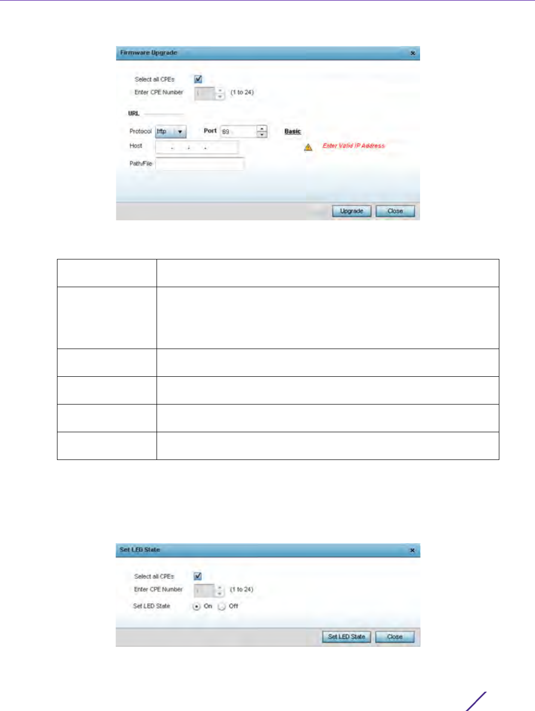
Dashboard
Wireless Controller and Service Platform System Reference Guide 4 - 19
Figure 4-14 T5 Dashboard CPE Reload
18 Use the Reload screen to specify the CPEs to target for a T5 managed device firmware upgrade.
19 Select Upgrade to initiate the update from the T5 to the selected CPE device(s). Select Close to exit the
Firmware Upgrade popup.
20 Expand the CPE Management item from the T5 dashboard and select Set LED State to administrate the LED
behavior of the T5 managed CPE devices.
Figure 4-15 T5 Dashboard Set LED State
Select all CPEs Select this option to use the settings specified in the Firmware Upgrade
and Reload screens to update all T5’s managed CPE devices.
Enter CPE Number If wanting to administrate an update to a specific T5 managed CPE, use the
spinner control to select a specific CPE (1 - 24) for update. This option is
enabled only when Select all CPEs is disabled. Select Show Boot Data to
supply display the Primary and Secondary firmware versions utilized in the
update.
Protocol Select the FTP or TFTP communication protocol used for updating T5
managed CPE device firmware.
Port Use the spinner control, or manually set, the T5 device port used by the
selected transfer protocol for CPE device firmware updates.
Host Provide the numeric IP address of the resource used to update the CPE
device firmware.
Path/File Specify the correct directory path to the T5 managed CPE device firmware
file. Enter the complete relative path to the file.
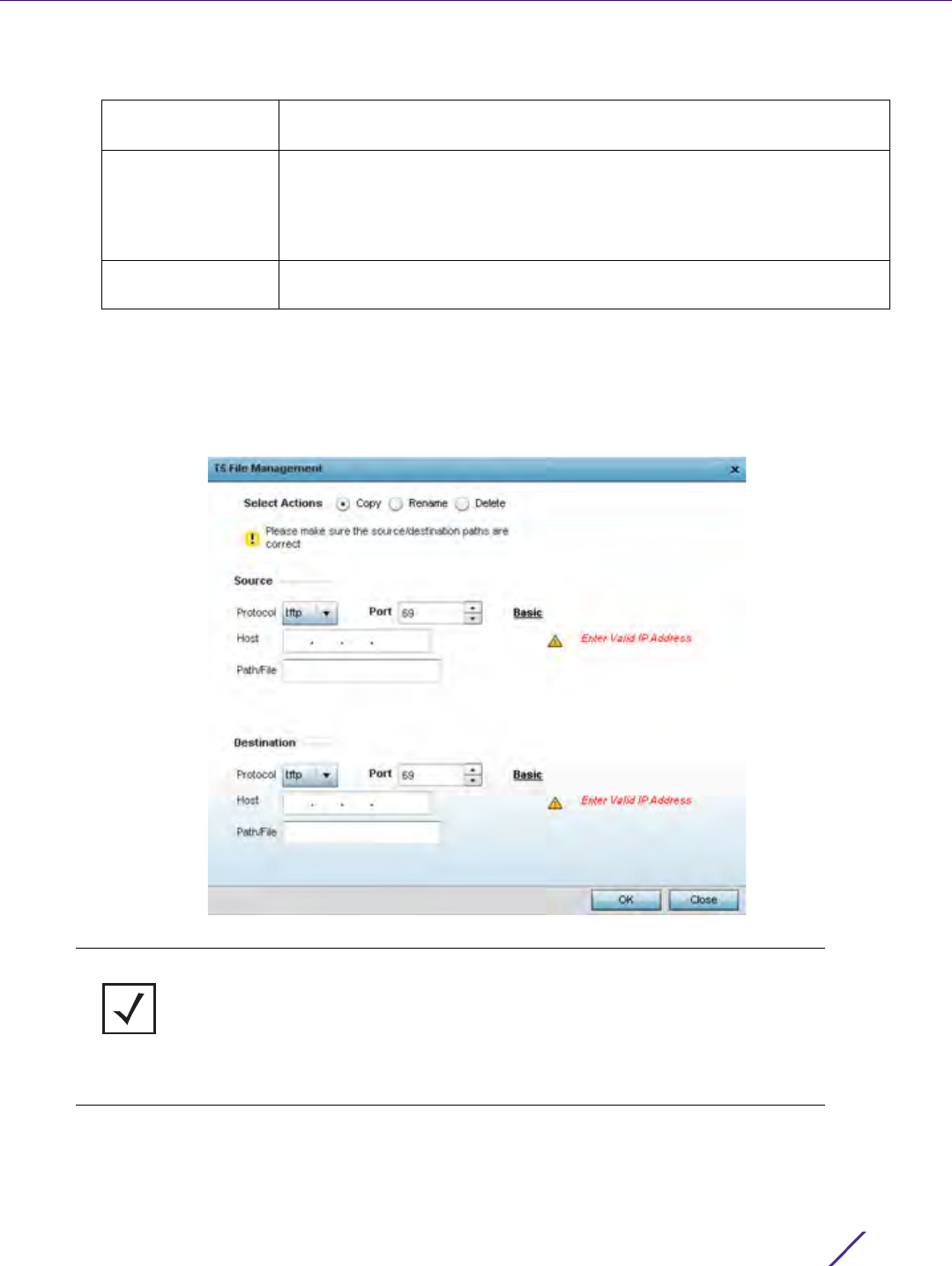
Dashboard
Wireless Controller and Service Platform System Reference Guide 4 - 20
21 Use the Set LED State screen to set the LED behavior T5 managed CPE devices.
22 Select Start LED State to initiate the LED behavior updates to the selected T5 managed CPE device(s). Select
Close to exit the Set LED State popup.
23 Select T5 File Management to set the Source and Destination addresses used for T5 device configuration file
updates.
Figure 4-16 T5 Dashboard T5 File Management
Select all CPEs Select this option to apply the administrated LED state to each T5
managed CPE device.
Enter CPE Number If wanting to set a specific T5 managed CPE LED, use the spinner control to
set the CPE to be impacted by the ELD state setting. This setting could be
quite useful in deployments where a specific CPE’s LED illumination could
be disruptive (such as a hospital etc.). This option is enabled only when
Select all CPEs is disabled.
Set LED State Define whether the LEDs remain on or off for the selected T5 managed
CPE devices. The default setting is On.
NOTE: The configuration parameters displayed within the T5 File Management
screen differ (increase or reduce) depending on whether Copy, Rename or Delete is
selected as the management action. When Copy is selected, both source and
destination protocols, ports, host addresses and paths are required for transfers. If
the action is to Rename a configuration, both source and destination paths are
required for name update. If the action is to Delete, only the path to the target file
is required. All supplied paths and addresses must be set correctly for the selected
action to be successful.

Dashboard
Wireless Controller and Service Platform System Reference Guide 4 - 21
24 Set the following T5 File Management Source and/or Destination transfer protocols and address information.
Options differ depending on selected Copy, Rename or Delete file management action.
25 Select OK to apply the selected file management action. Select Close to exit the T5 File Management popup.
4.4.4 EX3500 Switch Dashboard
The EX3500 series switch is a Gigabit Ethernet Layer 2 switch with either 24 or 48 10/100/1000-BASE-T ports, and
four small form factor pluggable (SFP) transceiver slots for fiber connectivity. Each 10/100/1000 Mbps port
supports both the IEEE 802.3af and IEEE 802.3at-2009 PoE standards. Each EX3500 series switch includes an
SNMP-based management agent, which provides both in-band and out-of-band access for management. An
EX3500 series switch utilizes an embedded HTTP Web agent and command line interface (CLI) somewhat
different from the WiNG operating system, while still enabling the EX3500 series switch to provide WiNG
controllers PoE and port management resources.
Going forward NX9600, NX9500, NX7500, NX5500 WiNG managed services platforms and WiNG VMs can
discover, adopt and partially manage EX3500 series Ethernet switches, as DHCP option 193 has been added to
support external device adoption. DHCP option 193 is a simplified form of DHCP options 191 and 192 used by WiNG
devices currently. DHCP option 193 supports pool1, hello-interval and adjacency-hold-time parameters.
Selected Action Select Copy to enable parameters where the correct source and destination
T5 device port, host IP address and directory path must be specified. Select
Rename to correctly provide the source and destination directory paths of
a renamed T5 configuration file. Select Delete to define the correct
directory path of a target T5 configuration file to delete and remove. The
default setting is Copy.
Protocol Select the FTP or TFTP communication protocol used for updating T5 file
transfers. This option is only available when Copy is the selected action.
Port Use the spinner control, or manually set, the T5 device port used by the
selected transfer protocol. This option is only available when Copy is the
selected action.
Host Provide the numeric IP address of the resource used to update the CPE
device firmware. This option is only available when Copy is the selected
action.
Path/File Specify the correct directory path to the location(s) of the source and
destination T5 device addresses. This option is only available when Copy is
the selected action.
Source If Renaming or Deleting a T5 configuration file, correctly enter the directory
path of the target file to be renamed or deleted.
Destination If Renaming a T5 configuration file, correctly enter the directory path of the
target file to be renamed.
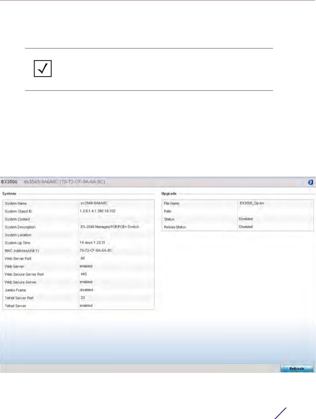
Dashboard
Wireless Controller and Service Platform System Reference Guide 4 - 22
When adopted to a managing controller or service platform, an EX3500 switch can display a unique dashboard
helpful to administrators to better assess the interoperability of the selected EX3500 with its connected controller
or service platform.
To review an EX3500 switch dashboard:
1Select
Dashboard.
2Select
Summary if it’s not already selected by default.
3Expand the
System node to display RF Domains.
4 Select and expand a RF Domain to expose its member controllers or service platforms.
5 Select an EX3500 switch from amongst the devices listed.
Figure 4-17 EX3500 Dashboard
NOTE: To enable the adoption of an EX3500 switch, the Allow Adoption of
External Devices option must be enabled. For more information, refer to
Adoption Overrides (Controllers Only) on page 5-48.

Dashboard
Wireless Controller and Service Platform System Reference Guide 4 - 23
6 Refer to the following System information to assess dashboard information for the selected EX3500 switch.
7 Refer to the Upgrade field to assess the EX3500’s current firmware and upgrade configuration status.
System Name Displays the administrator assigned system name of the selected EX3500
switch.
System Object ID Lists the numeric ID used to determine the monitoring capabilities of the
EX3500 switch.
System Contact Lists the EX3500 switch administrative contact assigned to respond to
events created by, or impacting, this selected EX3500 switch and the RF
Domain devices it helps support.
System Description Displays the administrator defined system description provided by the
administrator upon initial deployment of this particular EX3500 switch.
System Location Lists a 255 character maximum EX3500 switch location reflecting the
switch’s physical deployment location.
System Up Time Displays the cumulative time since this EX3500 was last rebooted or lost
power.
MAC Address (Unit
1)
Lists the factory encoded MAC address of the selected EX3500 as its
hardware identifier.
Web Server Port Displays the Web server port the EX3500 is using. Port 80 is the default
port the Web server expects to listen to.
Web Server Lists whether the Web server facility is enabled/disabled between this
selected EX3500 switch and its connected controller or service platform. A
Web server is a program using a client/server model and the Hypertext
Transfer Protocol (HTTP) to serve files forming Web pages to Web
resource requesting clients.
Web Secure Server
Port
Lists the numeric virtual server port providing secure Web resources with
the selected EX3500. Any system with multiple open ports, multiple
services and multiple scripting languages is vulnerable simply because it
has so many points of entry to watch. The secure open port has been
specifically designated and utilizes the latest security patches and
updates.
Web Secure Server Lists whether the secure Web server functionality has been enabled or
disabled for the selected EX3500’s management session with the WiNG
controller or service platform.
Jumbo Frame Lists whether support for jumbo Ethernet frames with more than 1500
bytes of payload has been enabled or disabled. Jumbo frames support up
to 9000 bytes, but variations must be accounted for. Many Gigabit
Ethernet switches and Gigabit Ethernet network interface cards support
jumbo frames. Some Fast Ethernet switches and Fast Ethernet network
interface cards also support jumbo frames.
Telnet Server Port Lists the numeric Telnet server port used with the selected EX3500’s
session with the WiNG controller or service platform to test for open
ports. The listed port is the port number where the server is listening.
Telnet Server Displays whether Telnet functionality is currently enabled or disabled for
the selected EX3500 switch.
Filename Lists the target firmware file queued for subsequent uploads to the
selected EX3500 switch.

Dashboard
Wireless Controller and Service Platform System Reference Guide 4 - 24
Periodically select Refresh to update the statistics counters to their latest values.
4.5 Access Point Screen
The Access Point screen displays system-wide network status for standalone or controller connected Access
Points. The screen is partitioned into the following tabs:
•Access Point Health – The Health tab displays information about the state of the Access Point managed
network.
•Access Point Inventory – The Inventory tab displays information on the physical devices managed within the
Access Point managed network.
4.5.1 Access Point Health
To assess Access Point network health:
1Select
Dashboard.
2Select
Summary if it’s not already selected by default.
3Expand the
System node to display RF Domains.
4 Select and expand a RF Domain to expose its member controllers or service platforms.
5 Select a controller or service platform and expand the menu item to display connected Access Points.
6 Select an Access Point. The Health tab display by default.
Path Lists the complete relative path to the EX3500 switch firmware file
defined for subsequent upgrades.
Status‘ Lists whether a device firmware upgrade is currently enabled and queued
for the selected EX3500 or is currently disabled.
Reload Status Displays the selected EX3500’s current firmware reload status.
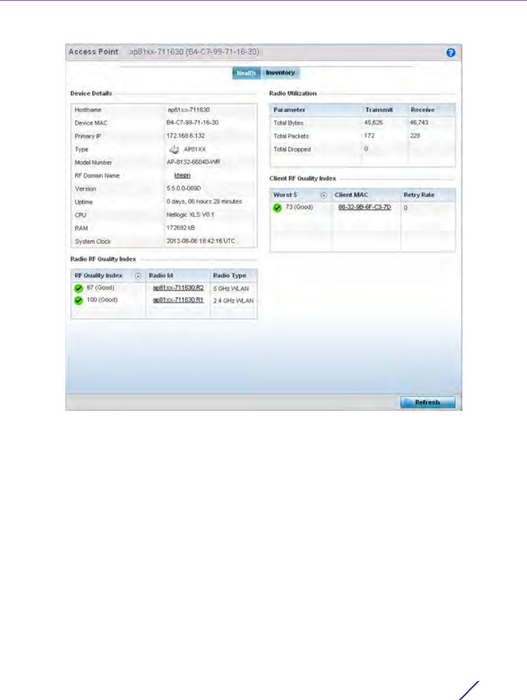
Dashboard
Wireless Controller and Service Platform System Reference Guide 4 - 25
Figure 4-18 Access Point screen - Health tab
The Device Detail field displays the following information about the selected Access Point:
•Hostname - Lists the administrator assigned name of the selected Access Point.
•Device MAC - Lists the factory encoded MAC address of the selected Access Point.
•Primary IP Address - Lists the IP address assigned to the Access Point as a network identifier.
•Type - Indicates the Access Point model type. An icon representing the Access Point is displayed along with
the model number.
•RF Domain Name - Lists the RF Domain to which the Access Point belongs. The RF Domain displays as a link
that can be selected to display Access Point RF Domain membership data in greater detail.
•Model Number - Lists the specific model number of the Access Point.
•Version - Lists the version of the firmware running on the Access Point. Compare this version against the
version currently on the support site to ensure the Access Point has the latest feature set available.
•Uptime - Displays the duration the Access Point has been running from the time it was last restarted.
•CPU - Displays the CPU installed on this Access Point.
•RAM - Displays the amount of RAM available for use in this system.
•System Clock - Displays the current time on the Access Point.
•The
Radio RF Quality Index displays a table of RF quality per radio. It is a measure of the overall
effectiveness of the RF environment displayed in percentage. It is a function of the connect rate in both
directions, the retry rate and error rate. The quality is measured as:

Dashboard
Wireless Controller and Service Platform System Reference Guide 4 - 26
-0-20 - Very poor quality
-20-40 - Poor quality
-40-60 - Average quality
- 60-100 - Good quality
•The Radio Utilization Index area displays how efficiently the RF medium is used. Radio utilization is defined
as the percentage of current throughput relative to the maximum possible throughput for the radio. The
Radio Utilization displays radios in terms of the number of associated wireless clients and percentage of
utilization. It also lists packets types transmitted and received.
•The
Client RF Quality Index displays a table of RF quality on a per client basis. It is a measure of the overall
effectiveness of the RF environment displayed in percentage. It is a function of the connect rate in both
directions, the retry rate and the error rate. This area of the screen displays the average quality index for a
client. The table lists bottom five (5) of the RF quality values by client. The quality is measured as:
-0-20 - Very poor quality
-20-40 - Poor quality
-40-60 - Average quality
- 60-100 - Good quality
4.5.2 Access Point Inventory
The Access Point Inventory tab displays granular data on devices managed by the selected Access Point.
Information is displayed in easy to read tables and graphs.
To assess Access Point network health:
1Select
Dashboard.
2Select Summary if it’s not already selected by default.
3Expand the System node to display RF Domains.
4 Select and expand a RF Domain to expose its member controllers or service platforms.
5 Select a controller or service platform and expand the menu item to display connected Access Points.
6Select an Access Point.
7 Select the Inventory tab.
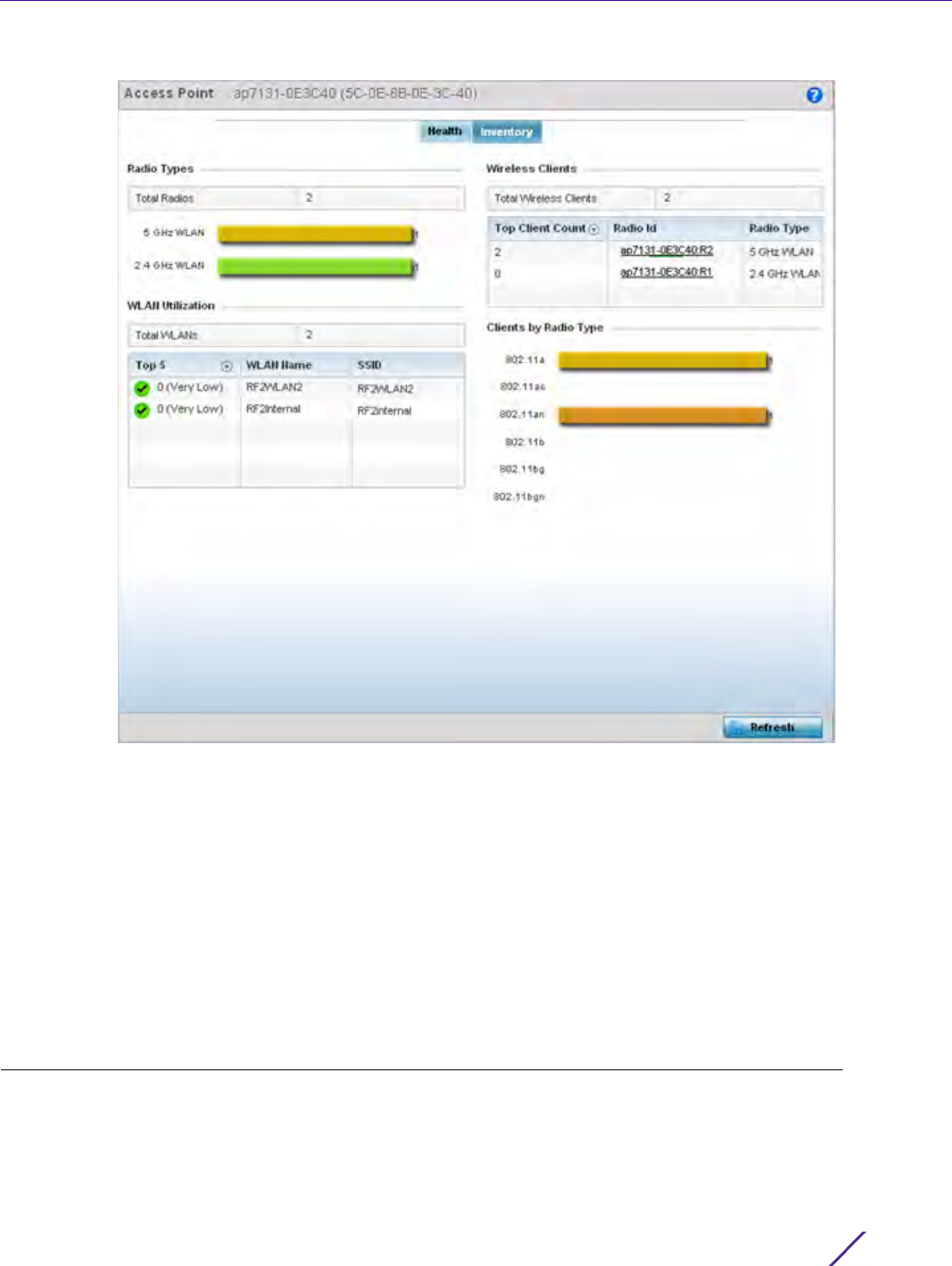
Dashboard
Wireless Controller and Service Platform System Reference Guide 4 - 27
Figure 4-19 Access Point screen - Inventory tab
The information within the Inventory tab is partitioned into the following fields:
•The
Radios Type field displays the total number of radios utilized by this Access Point. The graph lists the
number of radios in the 2.4 GHz and 5 GHz radio bands and funtioning as a sensor.
•The
WLAN Utilization table displays utilization statistics for controller or service platform WLAN
configurations. Information displays in two tables. The first table lists the total number of WLANs managed
by this system. The second table lists the top five (5) WLANs in terms of the usage percentage along with
their name and network identifying SSID.
•The
Wireless Clients table lists clients managed by this Access Point by connected client count. Information
is presented in two (2) tables and a graph. The first table lists the total number of clients managed by the
listed Access Point. The second lists the top five (5) radios in terms of the number of connected clients. The
graph just below the table lists the number of clients by radio type.
4.6 Network View
The Network View functionality displays device association connectivity amongst controllers, service platforms,
Access Point radios and wireless clients. This association is represented by a number of different graphs.
To review the wireless controller’s Network Topology, select Dashboard > Network View.
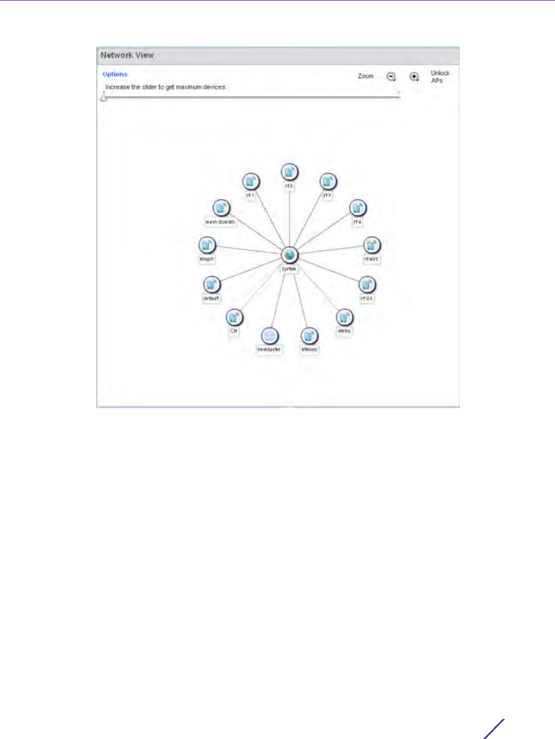
Dashboard
Wireless Controller and Service Platform System Reference Guide 4 - 28
Figure 4-20 Network View Topology
• The screen displays icons for the different views available to the system. Apart from device specific icons, the
following three icons are available:
•default – Displays information about the default RF Domain.
•system – Displays information about the current system.
•cluster – Displays information about clusters managed by this system.
Use the icons to navigate quickly within top level groupings.
The middle field displays a Network View, or graphical representation of the network. Nodes display whether or
not they are members of a cluster or mesh domain. Use this information to assess whether the topology of the
network has changed in such a manner that devices need to be added or moved. This field changes to display a
graphical network map.
Use the Lock / Unlock icon in the upper right of the screen to prevent users from moving APs around within the
specified area.
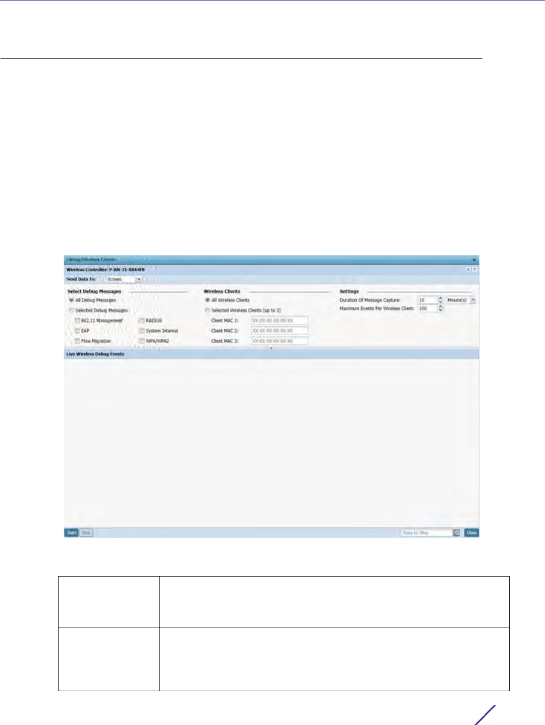
Dashboard
Wireless Controller and Service Platform System Reference Guide 4 - 29
4.7 Debug Wireless Clients
An administrator has the ability to select a RF Domain and capture connected client debug messages at an
administrator assigned interval and location. Client debug information can either be collected historically or in real-
time.
To troubleshoot issues with wireless client connectivity within a controller, service platform or Access Point
managed RF Domain:
1Select
Dashboard.
2Expand the System node to display controller, service platform or Access Point managed RF Domains.
3 Select and expand a RF Domain and click on the down arrow to the right of the RF Domain’s name
4Select
Troubleshooting.
5Select
Debug Wireless Clients.
Figure 4-21 Debug Wireless Clients screen
6 Refer to the following remote debug information for RF Domain member connected wireless clients:
RF Domain Displays the administrator assigned name of the selected RF Domain used
for wireless client debugging. RF Domains allow administrators to assign
configuration data to multiple devices deployed in a common coverage
area, such as in a floor, building or site.
Send Data To Use the Send Data To drop-down menu to select where wireless client
debug messages are collected. If Screen is selected the wireless client
debug information is sent to the Live Wireless Debug Events window at the
bottom of the dialog window. If File is selected, the file location must be
specified in the File Location section of the window.

Dashboard
Wireless Controller and Service Platform System Reference Guide 4 - 30
When all configuration fields are complete, select Start to start the wireless client debug capture. If information is
being sent to the screen it displays in the Live Wireless Debug Events section. If the data is being sent to a file,
Select Debug
Messages
Select All Debug Messages, to display all wireless client debug information
for the selected wireless clients on the current RF Domain. Choose Selected
Debug Messages to specify which types of wireless client debug messages
to display. If the Selected Debug Messages radio button is selected, you can
display information for any combination of the following:
- 802.11 Management
- EAP
- Flow Migration
- RADIUS
- System Internal
- WPA/WPA2
Wireless Clients Select All Wireless Clients to display debug information for all wireless
clients currently associated to the current RF Domain. Choose Selected
Wireless Clients to display information only for specific wireless clients
(between 1 and 3). If the Selected Wireless Clients radio button is selected
enter the MAC address for up to three wireless clients. The information
displayed or logged to the file will only be from the specified wireless
clients.
Duration of
Message Capture
Use the spinner controls to select how long to capture wireless client
debug information. This can range between 1 second and 24 hours, with the
default value being 1 minute.
Maximum Events
Per Wireless Client
Use the spinner controls to select the maximum number of debug
messages displayed per wireless client. Set the number of messages from 1
- 9999 events with the default value being 100 events.
File Location When the Send Data To field is set to File, the File Location configuration
displays below the configuration section. If Basic is selected, enter the URL
in the following format:
URL Syntax:
tftp://<hostname|IP>[:port]/path/file
ftp://<user>:<passwd>@<hostname|IP>[:port]/path/file
IPv6 URL Syntax:
tftp://<hostname|[IPv6]>[:port]/path/file
ftp://<user>:<passwd>@<hostname|[IPv6]>[:port]/path/file
If Advanced is selected, configure the Target, Port, Host/IP, User, Password
and optionally the path for the wireless client debug log file you wish to
create.
Live Wireless
Debug Events
When the Send Data To field is set to Screen, this area displays live debug
information for connected wireless clients in the selected RF Domain.
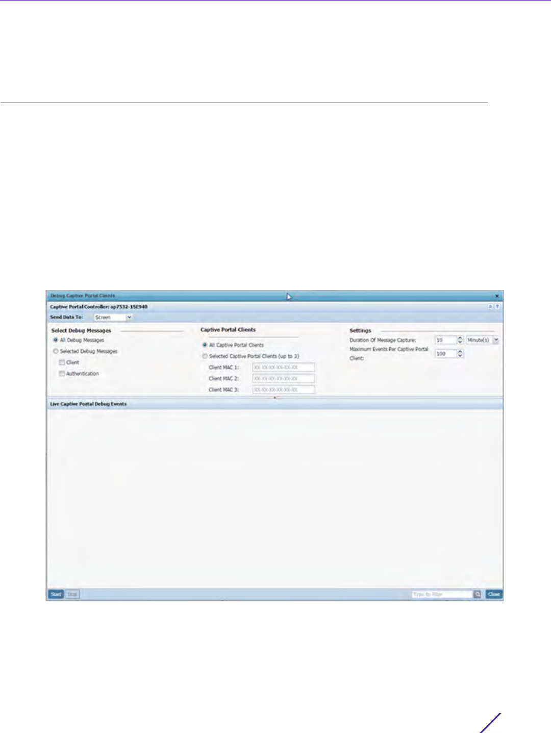
Dashboard
Wireless Controller and Service Platform System Reference Guide 4 - 31
that file populates with remote debug information. If you have set a long message capture duration and wish to
end the capture early, select Stop.
4.8 Debug Captive Portal Clients
An administrator can select a RF Domain and capture captive portal client and authentication debug messages at
an administrator assigned interval and location. Captive portal debug information can either be collected
historically or in real-time.
To troubleshoot captive portal client debug messages:
1Select
Dashboard.
2Expand the System node to display controller, service platform or Access Point managed RF Domains.
3 Select and expand a RF Domain and click on the down arrow to the right of the RF Domain’s name
4Select
Troubleshooting.
5Select
Captive Portal Clients.
Figure 4-22 Debug Wireless Clients screen
6Use the Send Data To drop-down menu to select where captive portal debug messages are collected. If Screen
is selected, information is sent to the Live Wireless Debug Events window at the bottom of the screen. If File is
selected, the file location must be specified in the File Location field.

Dashboard
Wireless Controller and Service Platform System Reference Guide 4 - 32
7Select
Debug Message settings to refine how captive portal client debug messages are trended:
8Set
Captive Portal Clients filter options to refine which clients are included in the debug messages.
9 Define the following captive portal client Settings to determine how messages are trended:
10 When all configuration fields are complete, select Start to start the captive portal client debug message
capture. Information sent to the screen displays in the Live Captive Portal Debug Events field. If you have set a
long message capture duration and wish to end the capture early, select Stop.
4.9 Packet Capture
An administrator can capture connected client packet data based on the packet’s address type or port on which
received. Dropped client packets can also be trended to assess RF Domain client connectivity health.
To administrate RF Domain packet captures:
1Select
Dashboard.
2Expand the System node to display controller, service platform or Access Point managed RF Domains.
3 Select and expand a RF Domain and click on the down arrow to the right of the RF Domain’s name
4Select
Troubleshooting.
5Select
Packet Capture.
All Debug Messages Select this option to capture all captive portal client and captive portal
authentication request events collectively without filtering by type.
Select Debug
Messages
Choose Selected Debug Messages to specify the type of captive portal
event messages to display. Options include captive portal client events and
events specific to captive portal authentication requests.
All Captive Portal
Clients
Select All Captive Portal Clients to display debug information for each client
utilizing a captive portal for network access within the selected RF Domain.
Select Captive
Portal Clients (up to
3)
Optionally display captive portal debug messages for specific clients (1 - 3).
Enter the MAC address for up to three wireless clients. The information
displayed or logged to the file is only from the specified wireless clients.
Change the client MAC addresses as needed when clients are no longer
utilizing the RF Domain’s captive portal resources.
Duration of
Message Capture
Use the spinner controls to set the message capture interval for captive
portal debug information. This can range between 1 second and 24 hours.
Maximum Events
Per Captive Portal
Client
Use the spinner controls to select the maximum number of captive portal
event messages displayed per RF Domain member client. Set the number
of messages from 1 - 9999 events with the default value being 100 events.

Dashboard
Wireless Controller and Service Platform System Reference Guide 4 - 33
Figure 4-23 Packet Capture screen
6 Refer to the following packet capture data for RF Domain member connected wireless clients:
RF Domain Displays the administrator assigned name of the selected RF Domain used
for wireless client packet captures. RF Domains allow administrators to
assign configuration data to multiple devices deployed in a common
coverage area, such as in a floor, building or site.
Send Data To Use the Send Data To drop-down menu to select where wireless client
packet capture messages are collected. If Screen is selected client packet
capture data is sent to the Live Wireless Debug Events window at the
bottom of the dialog window. If File is selected, the file location must be
specified in the File Location section of the window.
Dropped Select Dropped to create an event entry each time a packet is dropped
from a client connected to a RF Domain member device. Use this
information to assess whether a particular RF Domain is experiencing high
levels of dropped packets that may require administration to distribute
client connections more evenly.
Interface Select Interface to specify packet capture on a specific interface on the
current RF Domain. If Interface is selected, specify the interface name and
number and specify a Packet Direction
On a Radio (802.11) Select On a Radio (802.11) to capture packets only on 802.11 radios. If
selecting this option, specify which radios should be used and specify a
Packet Direction.

Dashboard
Wireless Controller and Service Platform System Reference Guide 4 - 34
7Select
Start to begin the packet capture. Information sent to the screen displays in the lower portion of the
window. If the data is being sent to a file, that file populates with the packet capture information. If you have
set a long message capture duration and wish to end the capture early, select Stop.
Filter (MAC, IP,
Protocol, Port)
Filter packet captures based on specific criteria. Select one or more of the
following and specify the relevant information:
- Filter by MAC
- Filter By IP
- IP Protocol
- Port
Maximum Packet
Count
Set the Maximum Packet Count to limit the number of packets captured for
trending. Set this value between 1 - 10000 packets, with a default value of
200.

5 -1
Wireless Controller and Service Platform System Reference Guide
5
Device Configuration
Managed devices can either be assigned unique configurations or have existing RF Domain or Profile
configurations modified (overridden) to support a requirement that dictates a device’s configuration be
customized from the configuration shared by its profiled peer devices.
When a device is initially managed by the controller or service platform, it requires several basic configuration
parameters be set (system name, deployment location etc.). Additionally, the number of permitted device licenses
needs to be accessed to determine whether a new Access Point can be adopted.
Refer to the following to set a device’s basic configuration, license and certificate usage:
•Basic Configuration
•Basic Device Configuration
•Auto Provisioning Policies
•Managing an Event Policy
•Managing MINT Policies
RF Domains allow administrators to assign configuration data to multiple devices deployed in a common coverage
area (floor, building or site). In such instances, there’s many configuration attributes these devices share as their
general client support roles are quite similar. However, device configurations may need periodic refinement
(overrides) from their original RF Domain administered design. For more information, see RF Domain Overrides on
page 5-32.
Profiles enable administrators to assign a common set of configuration parameters and policies to controller or
service platforms and Access Points. Profiles can be used to assign shared or unique network, wireless and security
parameters to wireless controllers and Access Points across a large, multi segment, site. The configuration
parameters within a profile are based on the hardware model the profile was created to support. The controller
and service platform supports both default and user defined profiles implementing new features or updating
existing parameters to groups of controllers, service platforms or Access Points.
However, device profile configurations may need periodic refinement from their original administered
configuration. Consequently, a device profile could be applied an override from the configuration shared amongst
numerous peer devices deployed within a particular site. For more information, see Profile Overrides on page 5-38.
Adoption is the process an Access Point uses to discover controller or service platforms available in the network,
pick the most desirable, establish an association, obtain its configuration and consider itself provisioned.
At adoption, an Access Point solicits and receives multiple adoption responses from available controllers or service
platforms on the network. Modify existing adoption policies or create a new one as needed to meet the adoption
requirements of a device and its assigned profile. For more information, see Auto Provisioning Policies on page 5-
268.
Lastly, use Configuration > Devices to define and manage a critical resource policy. A critical resource policy
defines a list of device IP addresses on the network (gateways, routers etc.). The support of these IP address is
interpreted as critical to the health of the network. These devices addresses are pinged regularly by the controller
or service platform. If there’s a connectivity issue, an event is generated stating a critical resource is unavailable.
For more information, see Overriding a Profile’s Critical Resource Configuration on page 5-233.
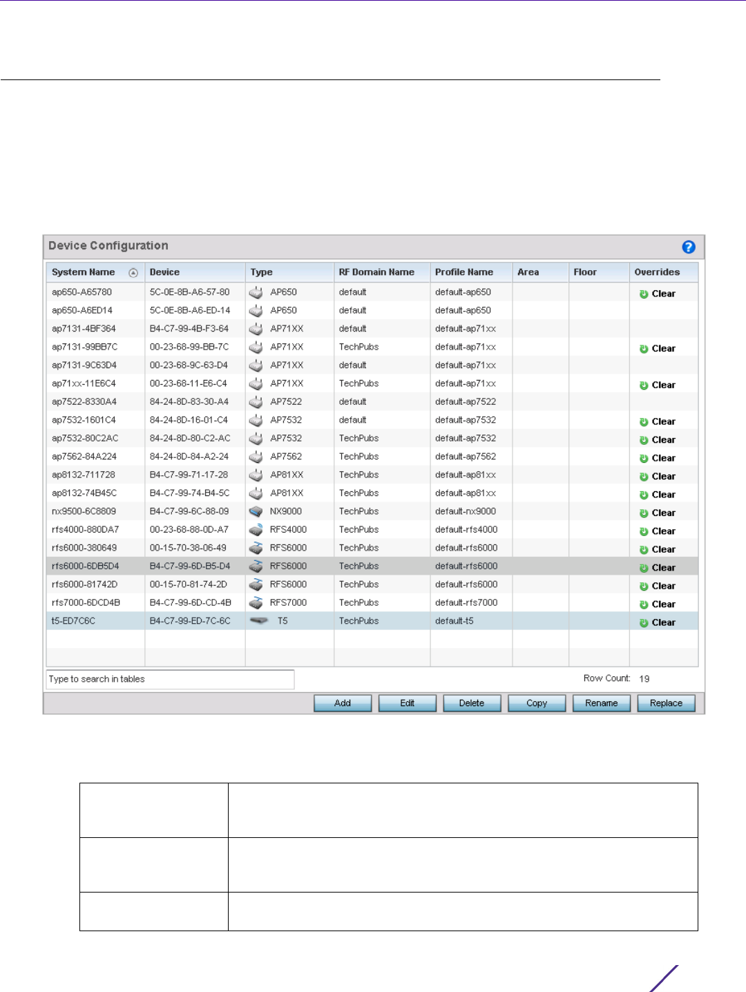
Device Configuration
Wireless Controller and Service Platform System Reference Guide 5 - 2
5.1 Basic Configuration
Device Configuration
To assign a Basic Configuration:
1 Select the Configuration tab from the Web UI.
2Select
Devices from the Configuration tab.
The Device Configuration screen displays a list of devices.
Figure 5-1 Device Configuration screen
Refer to the following device settings to determine whether a configuration update or RF Domain or Profile
change is warranted:
System Name Displays the name assigned to the device when the basic configuration
was defined. This is also the device name that appears within the RF
Domain or Profile the device supports.
Device Displays the device’s factory assigned MAC address used as hardware
identifier. The MAC address cannot be revised with the device’s
configuration.
Type Displays the device model for the listed controller, service platform or
Access Point.
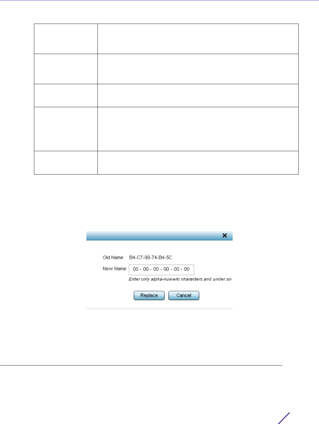
Device Configuration
Wireless Controller and Service Platform System Reference Guide 5 - 3
3Select
Add to create a new device, select Edit to modify an existing device or select Delete to remove an
existing device.Optionally Copy or Rename a device as needed.
4Use the Replace button to replace an existing access point with another Access Point. The Replace feature
enable you to swap an existing Access Point with a new one without disrupting normal operations. The
configuration of the old Access Point is automatically copied to the newly added Access Point. The following
screen is displayed.
Figure 5-2 Device Configuration screen - Replace
5 Enter the MAC address of the new Access Point in the New Name field and select the Replace button. The new
Access Point is added to the list of devices and the configuration from the old Access Point is applied to it. The
old Access Point is then removed from the device list.
5.2 Basic Device Configuration
Device Configuration
Setting a device’s Basic Configuration is required to assign a device name, deployment location, and system time.
Similarly, the Basic Configuration screen is where Profile and RF Domain assignments are made. RF Domains allow
RF Domain Name Lists RF Domain memberships for each listed device. Devices can either
belong to a default RF Domain based on model type, or be assigned a
unique RF Domain supporting a specific configuration customized to that
device model.
Profile Name Lists the profile each listed device is currently a member of. Devices can
either belong to a default profile based on model type, or be assigned a
unique profile supporting a specific configuration customized to that
model.
Area List the physical area where the controller or service platform is deployed.
This can be a building, region, campus or other area that describes the
deployment location.
Floor List the building Floor name representative of the location within the area
or building the controller or service platform was physically deployed.
Assigning a building Floor name is helpful when grouping devices in RF
Domains and Profiles, as devices on the same physical building floor may
need to share specific configuration parameters in respect to radio
transmission and interference requirements specific to that location.
Overrides The Overrides column contains an option to clear all profile overrides for
any devices that contain overrides. To clear an override, select the clear
button to the right of the device.
Device Configuration
Wireless Controller and Service Platform System Reference Guide 5 - 4
administrators to assign configuration data to multiple devices deployed in a common coverage area, such as in a
floor, building or site. Each RF Domain contains policies that can determine a Smart RF or WIPS configuration.
Profiles enable administrators to assign a common set of configuration parameters and policies to controllers,
service platforms and Access Points. Profiles can be used to assign common or unique network, wireless and
security parameters to wireless controllers and Access Points across a large, multi segment, site. The configuration
parameters within a profile are based on the hardware model the profile was created to support. A controller and
service platform support both default and user defined profiles implementing new features or updating existing
parameters to groups of peer devices and Access Points. The central benefit of a profile is its ability to update
devices collectively without having to modify individual device configurations one at a time.
To assign a device a Basic Configuration:
1 Select the Configuration tab from the Web UI.
2Select
Devices from the Configuration tab.
The Device Configuration screen displays a list of managed devices or peer controllers, service platforms or
Access Points.
3 Select a target device (by double-clicking it) from amongst those displayed.
Devices can also be selected directly from the Device Browser in the lower, left-hand, side of the UI.
The Basic Configuration screen displays by default.
NOTE: Once devices have been assigned membership in either a profile or RF
Domain, an administrator must be careful not to assign the device a configuration
update that removes it from membership from a RF Domain or profile. A RF
Domain or profile configuration must be re-applied to a device once its
configuration has been modified in a manner that differentiates it from the
configuration shared by the devices comprising the RF Domain or profile.
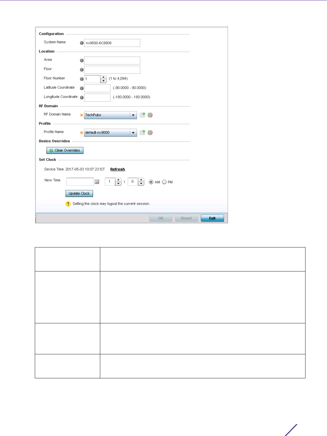
Device Configuration
Wireless Controller and Service Platform System Reference Guide 5 - 5
Figure 5-3 Basic Configuration screen
4 Set the following Configuration settings for the target device:
System Name Provide the selected device a system name up to 64 characters. This is
the device name that appears within the RF Domain or Profile the device
supports.
Area Assign the device an Area name representative of the location the
controller or service platform was physically deployed. The name cannot
exceed 64 characters. Assigning an area name is helpful when grouping
devices in RF Domains and profiles, as devices in the same physical
deployment location may need to share specific configuration parameters
in respect to radio transmission and interference requirements specific to
that location.
Floor Assign the target a device a building Floor name representative of the
location the Access Point was physically deployed. The name cannot
exceed 64 characters. Assigning a building Floor name is helpful when
grouping devices within the same general coverage area.
Floor Number Use the spinner control to assign a numerical floor designation in respect
to the floor’s actual location within a building. Set a value from 1 - 4094.
The default setting is the 1st floor.

Device Configuration
Wireless Controller and Service Platform System Reference Guide 5 - 6
5Use the RF Domain drop-down menu to select an existing RF Domain for device membership.
6 If a RF Domain configuration does not exist suiting the deployment requirements of the target device, select
the Create icon to create a new RF Domain configuration, or select the Edit icon to modify the configuration of
a selected RF Domain. For more information, see About RF Domains on page 9-1 or Managing RF Domains on
page 9-2.
7Use the Profile drop-down menu to select an existing device profile for multiple device deployment uniformity.
8 If a profile configuration does not exist suiting the deployment requirements of the target device, select the
Create icon to create a new profile configuration, or select the Edit icon to modify the configuration of a
selected profile. For more information, see General Profile Configuration on page 8-5.
9If necessary, select the Clear Overrides button to remove all existing overrides from the device.
10 Refer to the Set Clock parameter to update the system time of the target device.
11 Refer to the Device Time parameter to assess the device’s current time, or whether the device time is
unavailable. Select Refresh as required to update the device’s reported system time.
12 Use the New Time parameter to set the calendar day, hour and minute for the target device. Use the AM and
PM radio buttons to refine whether the updated time is for the morning or afternoon/evening.
13 When completed, select Update Clock to commit the updated time to the target device.
14 If a T5 controller is deployed, select it from the Type drop-down menu and configure CPE VLAN Settings, in
addition to the other parameters described in this section.
A T5 controller uses the a somewhat different operating system to manage its connected radio devices, as
opposed to the WiNG operating used by RFS controllers and NX service platforms. However, a T5 controller,
once enabled as a supported external device, can provide data to WiNG to assist in a T5’s management within
a WiNG supported subnet populated by both types of devices. The Customer Premises Equipment (CPEs) are
the T5 controller managed radio devices. These CPEs use a Digital Subscriber Line (DSL) as their high speed
Internet access mechanism using the CPE’s physical wallplate connection and phone jack.
15 Select OK to save the changes made to the screen. Selecting Reset reverts the screen to its last saved
configuration.
Latitude Coordinate Set the latitude coordinate where devices are deployed within a floor.
When looking at a floor map, latitude lines specify the east-west position
of a point on the Earth's surface. The exact location of a device
deployment can be ascertained by aligning the latitude and longitude
points on the earth’s surface.
Longitude
Coordinate
Set the longitude coordinate where devices are deployed within a floor.
When looking at a floor map, longitude lines specify the north-south
position of a point on the Earth's surface. The exact location of a device
deployment can be ascertained by aligning the longitude and latitude
points on the earth’s surface.
VLAN Set a VLAN from 1 - 4,094 used as a virtual interface for connections
between the T5 controller and its managed CPE devices.
Start IP Set a starting IP address used in a range of addresses available to T5
controller connecting CPE devices.
End IP Set an end IP address used in a range of addresses available to T5
controller connecting CPE devices.
Device Configuration
Wireless Controller and Service Platform System Reference Guide 5 - 7
5.2.1 License Configuration
Basic Device Configuration
Licenses are purchased directly for the number of permissible adoptions per controller, service platform or
managed cluster.
Managing infrastructure devices requires a license key to enable software functionality or define the number of
adoptable devices permitted. My Licenses is a Web based online application enabling you to request a license key
for license certificates for products.
The Licenses screen also contains a facility where new licenses can be applied to increase the number of device
adoptions permitted, or to allow the use of the advanced security features.
Each controller and service platform family has multiple models to choose from that range from zero licenses to
the maximum number that can be loaded for that specific SKU.
To configure a device’s a license configuration:
1 Select the Configuration tab from the Web UI.
2Select
Devices from the Configuration tab.
The Device Configuration screen displays a list of managed devices or peer controllers, service platforms or
Access Points.
3 Select a target device (by double-clicking it) from amongst those displayed within the Device Configuration
screen.
Devices can also be selected directly from the Device Browser in the lower, left-hand, side of the UI.
4Select
Licenses from the Device menu options.
NOTE: The Licenses screen is only available to wireless controllers capable of
sustaining device connections, and thus requires license support to set the
maximum number of allowed device connections. The License screen is not
available for Access Points.
NOTE: For detailed instructions on using My Licenses to add hardware or software
licenses and register certificates, refer to the My Licenses Users Guide, available at
www.extremenetworks.com/support.
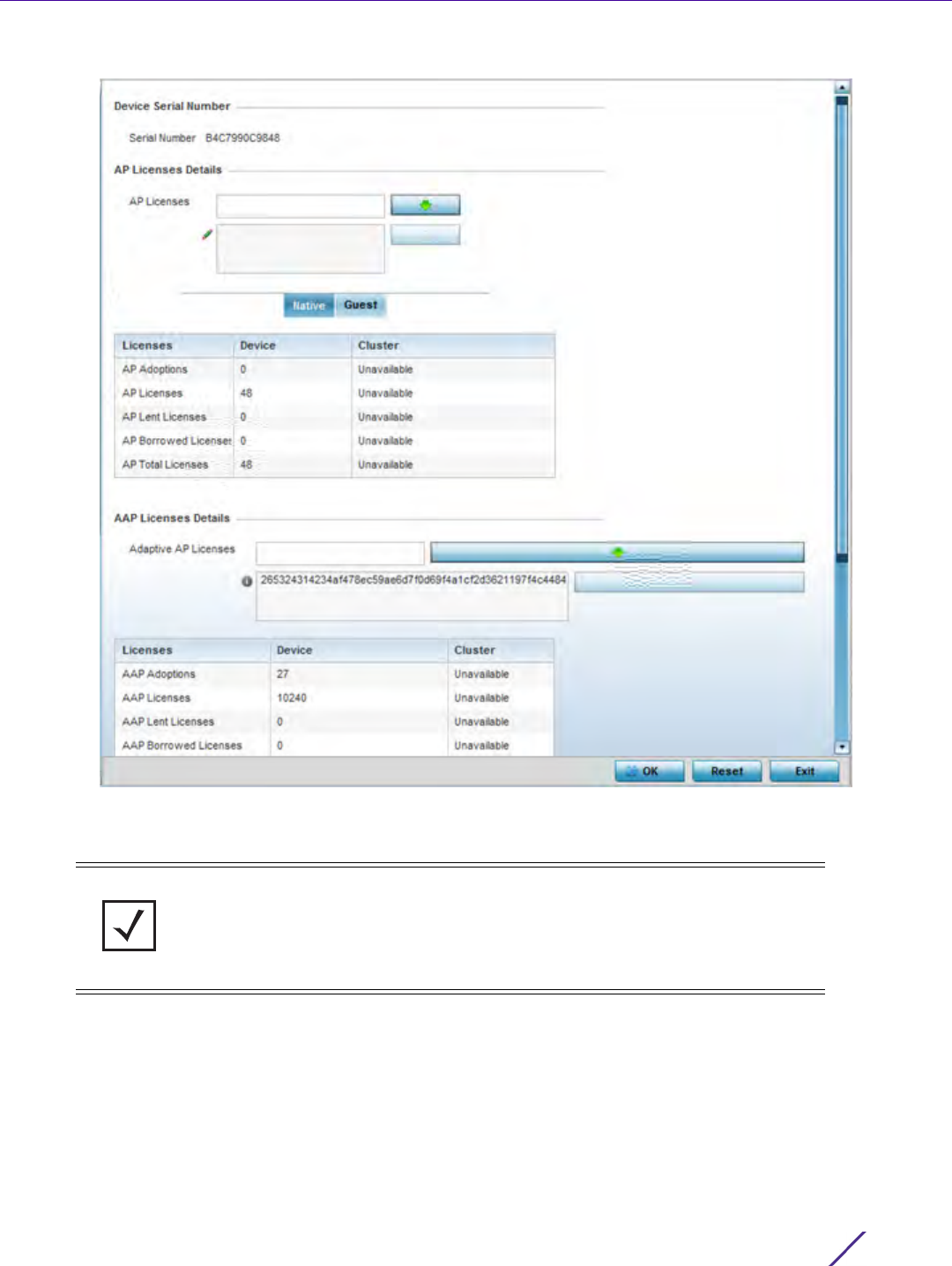
Device Configuration
Wireless Controller and Service Platform System Reference Guide 5 - 8
Figure 5-4 Device Licenses screen
The License screen displays the Device Serial Number of the controller or service platform generating the
license key.
NOTE: When assessing lent and borrowed license information, its important to
distinguish between site controllers and NOC controllers.
NOC controllers are NX9000, NX9500, NX9510, NX7500 and RFS6000.
Site controllers are NX5500, NX7500, RFS4000 and RFS6000.

Device Configuration
Wireless Controller and Service Platform System Reference Guide 5 - 9
5Review the AP Licenses table to assess the specific number of adoptions permitted, as dictated by the terms of
the current license. The Native tab displays by default. Select the Guest tab to display guest licenses.
AP Adoptions The Device column Lists the total number of AP adoptions made by the
controller or service platform. If the installed license count is 10 APs and
the number of AP adoptions is 5, 5 additional APs can still be adopted
under the terms of the license. The total number of APs adoptions varies
by platform, as well as the terms of the license. The Cluster column lists
the total number of AP adoptions made by the cluster membership (all
members). If the installed license count is 100 APs and the number of AP
adoptions is 50, 50 additional APs can still be adopted under the terms of
the AP licenses, pooled by the cluster members.
AP Licenses The Device column lists the number of APs available for adoption under
the restrictions of the license. This number applies to dependent mode
adaptive APs only, and not independent mode APs. The Cluster column
lists the number of APs available for adoption by cluster members under
the restrictions of the licenses, as pooled amongst the cluster members.
AP Lent Licenses Lent licenses are the total number of AP licenses the NOC controller lends
(if needed) to its site controllers so site controllers can adopt APs in
excess of its own installed AP license count. AP lent licenses can be non-
zero only in controllers currently configured as the NOC (NOC controller).
Lent Licenses is always zero in controllers configured as the site (site
controller).
AP Borrowed
Licenses
Borrowed licenses are the total number of AP licenses borrowed by the
site controller from the NOC controller (NOC controllers if a NOC
controller is in a cluster). AP borrowed licenses are always zero in the
NOC controller. AAP borrowed licenses can be non-zero only on site
controllers.
AP Total Licenses Lists the cumulative number of both Device and Cluster AP licenses
supported by the listed controller or service platform.
NOTE: The following is a licensing example: Assume there are two site controllers
(S1 and S2) adopted to a NOC controller (N1). S1 has 3 installed AP licenses, and S2
has 4 installed AP licenses. Eight APs seek to adopt on S1, and ten APs seek to
adopt on S2. N1 has 1024 installed licenses. N1 lends 5 (8-3) AP licenses to S1, and 6
(10-4) AP licenses to S2.
N1 displays the following in the Device column: AP Adoptions: 2 (site controllers S1
and S2) AP Licenses: 1024 AP Lent Licenses: 11 (5 to S1 + 6 to S2) AP Borrowed
Licenses: 0 AP Total Licenses: 1013 (1024 – 11 lent) S1 displays the following in the
Device column: AP Adoptions: 8 AP Licenses: 3 AP Lent Licenses: 0 AP Borrowed
Licenses: 5 AP Total Licenses: 8 (3 + 5 borrowed). S2 displays the following in the
Device column: AP Adoptions: 10 AP Licenses: 4 AP Lent Licenses: 0 AP Borrowed
Licenses: 6 AP Total Licenses: 10 (4 + 6 borrowed).

Device Configuration
Wireless Controller and Service Platform System Reference Guide 5 - 10
6Review the AAP Licenses table to assess the specific number of adoptions permitted, as dictated by the terms
of the current license.
7 Refer to the Feature Licenses field to apply licenses and provision advanced security and analytics features:
8 Refer to the Web Filtering License field if required to provide a 256 character maximum license string for the
Web filtering feature. Web filtering is used to restrict access to specific resources on the Internet.
9Select
OK to save the changes made to the applied licenses. Selecting Reset reverts the screen to its last saved
configuration.
5.2.2 Assigning Certificates
Basic Device Configuration
A certificate links identity information with a public key enclosed in the certificate. A certificate authority (CA) is a
network authority that issues and manages security credentials and public keys for message encryption. The CA
signs all digital certificates it issues with its own private key. The corresponding public key is contained within the
AAP Adoptions The Device column Lists the total number of AAP adoptions made by the
controller or service platform. If the installed license count is 10 APs and
the number of AAP adoptions is 5, 5 additional AAPs can still be adopted
under the terms of the license. The total number of AAPs adoptions varies
by platform, as well as the terms of the license. The Cluster column lists
the total number of AAP adoptions made by the cluster membership (all
members). If the installed license count is 100 APs and the number of
AAP adoptions is 50, 50 additional AAPs can still be adopted under the
terms of the AAP licenses, pooled by the cluster members.
AAP Licenses The Device column lists the number of AAPs available for adoption under
the restrictions of the license. This number applies to dependent mode
adaptive AAPs only, and not independent mode AAPs. The Cluster
column lists the number of AAPs available for adoption by cluster
members under the restrictions of the licenses, as pooled amongst the
cluster members.
AAP Lent Licenses Lent licenses are the total number of AAP licenses the NOC controller
lends (if needed) to its site controllers so site controllers can adopt
adaptive APs in excess of its own installed AAP license count. AAP lent
licenses can be non-zero only in controllers currently configured as the
NOC (NOC controller). Lent Licenses is always zero in controllers
configured as the site (site controller).
AAP Borrowed
Licenses
Borrowed licenses are the total number of AAP licenses borrowed by the
site controller from the NOC controller (NOC controllers if a NOC
controller is in a cluster). AAP borrowed licenses are always zero in the
NOC controller. AAP borrowed licenses can be non-zero only on site
controllers.
AAP Total Licenses Lists the cumulative number of both Device and Cluster AAP licenses
supported by the listed controller or service platform.
Advanced Security Enter the provided license key required to install the Role Based Firewall
feature and increase the number of IPSec VPN tunnels. The number of
IPSec tunnels varies by platform.
Analytics Licenses Enter the provided license key required to install Analytics (an enhanced
statistical management tool) for NX7500 and NX9000 series service
platforms.
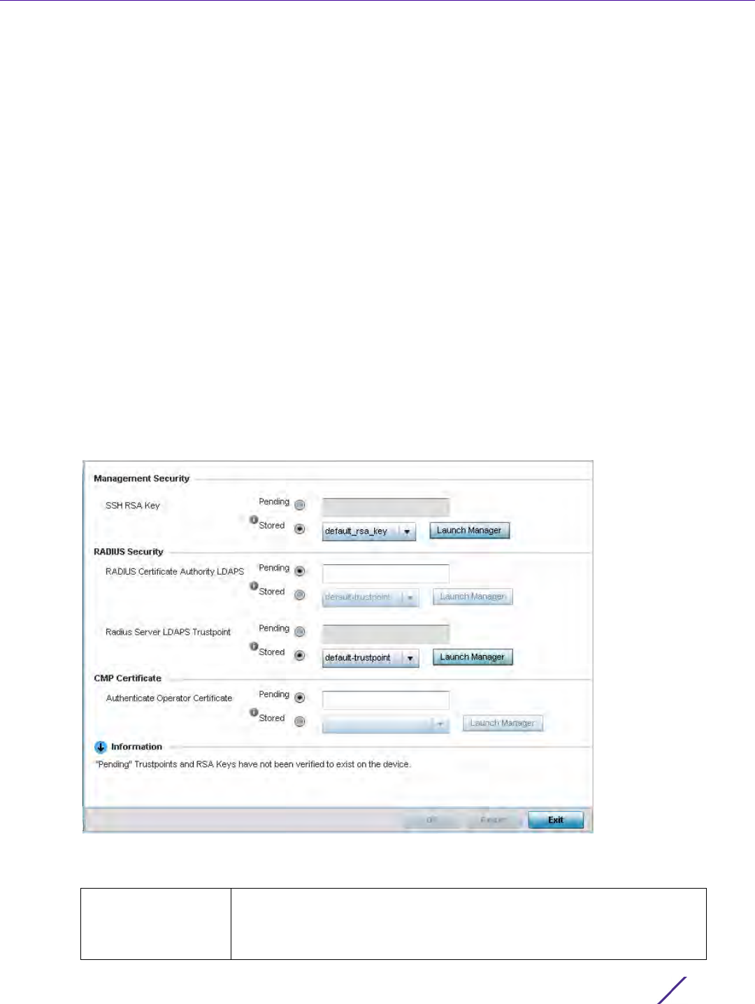
Device Configuration
Wireless Controller and Service Platform System Reference Guide 5 - 11
certificate and is called a CA certificate. A browser must contain the CA certificate in its Trusted Root Library so it
can trust certificates signed by the CA's private key.
Depending on the public key infrastructure, the digital certificate includes the owner's public key, the certificate
expiration date, the owner's name and other public key owner information. Each certificate is digitally signed by a
trustpoint. The trustpoint signing the certificate can be a certificate authority, corporation or individual. A
trustpoint represents a CA/identity pair containing the identity of the CA, CA-specific configuration parameters,
and an association with an enrolled identity certificate.
SSH keys are a pair of cryptographic keys used to authenticate users instead of, or in addition to, a username/
password. One key is private and the other is public key. Secure Shell (SSH) public key authentication can be used
by a requesting client to access resources, if properly configured. A RSA key pair must be generated on the client.
The public portion of the key pair resides with the controller or service platform, while the private portion remains
on a secure local area of the client.
To configure certificate usage:
1 Select the Configuration tab from the Web UI.
2Select
Devices from the Configuration tab.
The Device Configuration screen displays a list of managed devices or peer controllers, service platforms or
Access Points.
3Select
Certificates from the Device menu.
Figure 5-5 Device Certificates screen
4 Set the following Management Security certificate configurations:
SSH RSA Key Either use the default_rsa_key or select the Stored radio button to enable
a drop-down menu where an existing certificate can be used. To leverage
an existing key, select the Launch Manager button. For more information,
see RSA Key Management on page 5-21.

Device Configuration
Wireless Controller and Service Platform System Reference Guide 5 - 12
5 Set the following RADIUS Security certificate configurations:
6 Refer to the CMP Certificate field to optionally use Certificate Management Protocol (CMP) as an Internet
protocol to obtain and manage digital certificates in a Public Key Infrastructure (PKI) network. A Certificate
Authority (CA) issues the certificates using the defined CMP. Using CMP, a device can communicate to a CMP
supported CA server, initiate a certificate request and download the required certificates from the CA server.
CMP supports multiple request options through for device communicating to a CMP supported CA server. The
device can initiate a request for getting the certificates from the server. It can also auto update the certificates
which are about to expire.
Either use the server default-trustpoint or select the Stored radio button to enable a drop-down menu where
an existing certificate/trustpoint can be selected. To leverage an existing trustpoint, select the Launch Manager
button.
7Select
OK to save the changes made to the certificate configurations. Selecting Reset reverts the screen to its
last saved configuration.
For more information on the certification activities supported, refer to the following:
•Certificate Management
•RSA Key Management
•Certificate Creation
•Generating a Certificate Signing Request
5.2.2.1 Certificate Management
Assigning Certificates
A stored certificate can be leveraged from a different managed device if not wanting to use an existing certificate
or key. Device certificates can be imported and exported to and from the controller or service platform to a secure
remote location for archive and retrieval as required for other managed devices.
To configure trustpoints for use with certificates:
NOTE: Pending trustpoints and RSA keys are typically not verified as existing on a
device.
RADIUS Certificate
Authority
Either use the default-trustpoint or select the Stored radio button to
enable a drop-down menu where an existing certificate can be leveraged.
To leverage an existing certificate, select the Launch Manager button.
RADIUS Server
Certificate
Either use the default-trustpoint or select the Stored radio button to
enable a drop-down menu where an existing certificate/trustpoint can be
used. To leverage an existing trustpoint, select the Launch Manager
button.
RADIUS Certificate
Authority LDAPS
Either use the LDAP server default-trustpoint or select the Stored radio
button to enable a drop-down menu where an existing certificate can be
leveraged. To leverage an existing certificate, select the Launch Manager
button.
Radius Server LDAPS
Trustpoint
Either use the LDAP server default-trustpoint or select the Stored radio
button to enable a drop-down menu where an existing certificate/
trustpoint can be used. To leverage an existing trustpoint, select the
Launch Manager button.
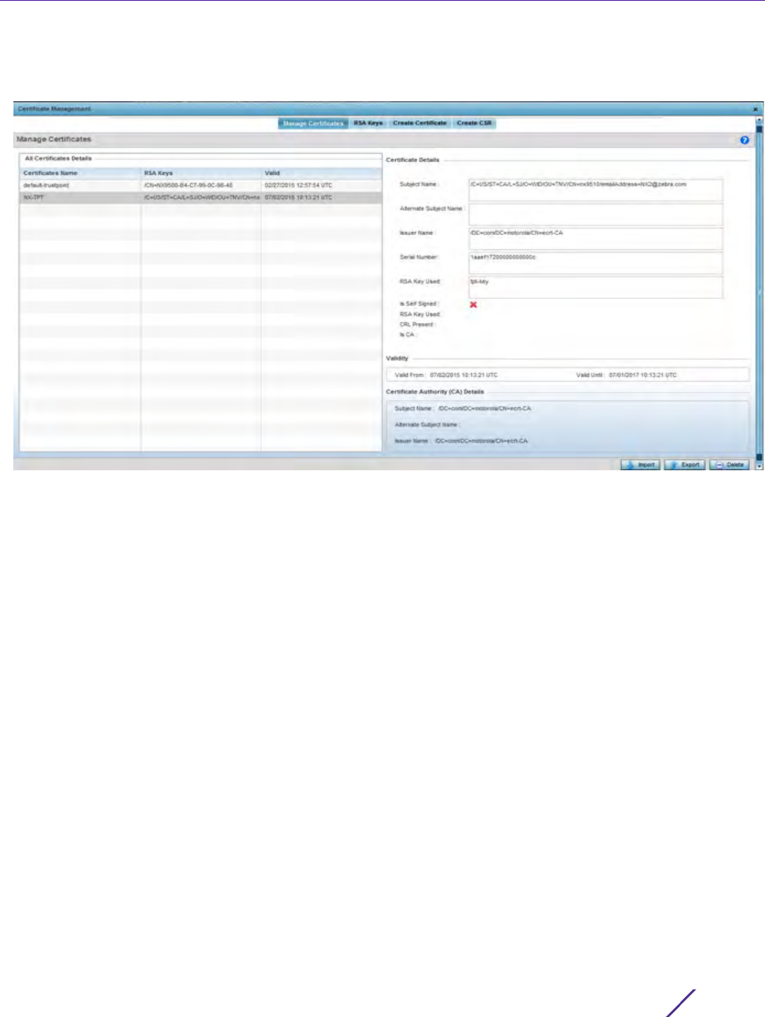
Device Configuration
Wireless Controller and Service Platform System Reference Guide 5 - 13
1Select
Launch Manager from either the HTTPS Trustpoint, SSH RSA Key, RADIUS Certificate Authority or RADIUS
Server Certificate parameters.
Figure 5-6 Certificate Management - Manage Certificates screen
The Certificate Management screen displays with the Manage Certificates tab displayed by default.
2 Select a device from amongst those displayed to review its certificate information.
3 Refer to the All Certificates Details to review the certificate’s properties, self-signed credentials, validity duration
and CA information.
4 To optionally import a certificate, select the Import button from the Certificate Management screen.
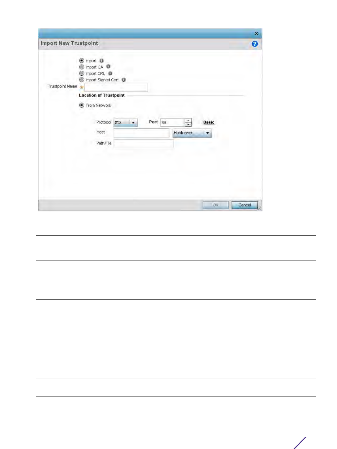
Device Configuration
Wireless Controller and Service Platform System Reference Guide 5 - 14
Figure 5-7 Certificate Management - Import New Trustpoint screen
5 Define the following configuration parameters required for the Import of the trustpoint.
Trustpoint Name Enter the 32 character maximum name assigned to the target trustpoint.
The trustpoint signing the certificate can be a certificate authority,
corporation or individual.
URL Provide the complete URL to the location of the trustpoint. If needed,
select Advanced to expand the dialog to display network address
information to the location of the target trustpoint. The number of
additional fields that populate the screen is also dependent on the
selected protocol.
Protocol Select the protocol used for importing the target trustpoint. Available
options include:
tftp
ftp
sftp
http
cf
usb1-4
Port Use the spinner control to set the port. This option is not valid for cf and
usb1-4.
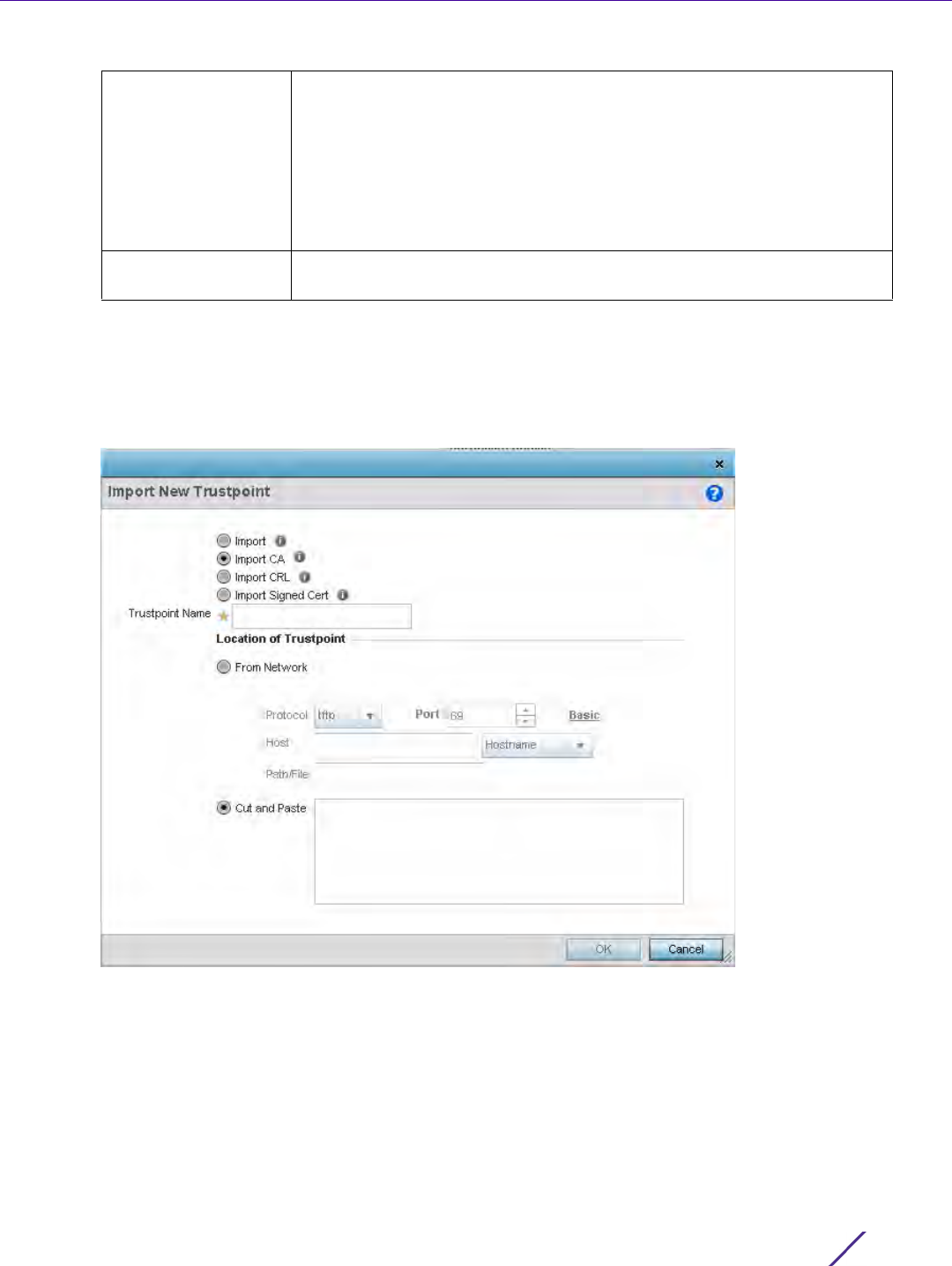
Device Configuration
Wireless Controller and Service Platform System Reference Guide 5 - 15
6Select
OK to import the defined trustpoint. Select Cancel to revert the screen to its last saved configuration.
7 To optionally import a CA certificate, select the Import CA button from the Certificate Management screen.
A CA is a network authority that issues and manages security credentials and public keys for message
encryption. The CA signs all digital certificates it issues with its own private key. The corresponding public key
is contained within the certificate and is called a CA certificate.
Figure 5-8 Certificate Management - Import CA Certificate screen
Host Provide the hostname string or numeric IP address of the server used to
import the trustpoint. Hostnames cannot include an underscore character.
This option is not valid for cf and usb1-4.
Select IPv4 Address to use an IPv4 formatted address as the host. Select
IPv6 Address to use an IPv6 formatted address as the host. IPV6 provides
enhanced identification and location information for computers on
networks routing traffic across the Internet. IPv6 addresses are composed
of eight groups of four hexadecimal digits separated by colons.
Path/File Specify the path to the trustpoint file. Enter the complete relative path to
the file on the server.

Device Configuration
Wireless Controller and Service Platform System Reference Guide 5 - 16
8 Define the following configuration parameters required for the Import of the CA certificate:
9Select
OK to import the defined CA certificate. Select Cancel to revert the screen to its last saved configuration.
10 Select the Import CRL button from the Certificate Management screen to optionally import a CRL to a controller
or service platform.
If a certificate displays within the Certificate Management screen with a CRL, that CRL can be imported. A
certificate revocation list (CRL) is a list of certificates that have been revoked or are no longer valid. A
certificate can be revoked if the CA had improperly issued a certificate, or if a private-key is compromised. The
most common reason for revocation is the user no longer being in sole possession of the private key.
For information on creating a CRL to use with a trustpoint, refer to Setting the Profile’s Certificate Revocation
List (CRL) Configuration on page 8-166.
Trustpoint Name Enter the 32 character maximum name assigned to the target trustpoint
signing the certificate. A trustpoint represents a CA/identity pair
containing the identity of the CA, CA specific configuration parameters,
and an association with an enrolled identity certificate.
URL Provide the complete URL to the location of the trustpoint. If needed,
select Advanced to expand the dialog to display network address
information to the location of the target trustpoint. The number of
additional fields populating the screen is dependent on the selected
protocol.
Advanced / Basic Click the Advanced or Basic link to switch between a basic URL and an
advanced location to specify trustpoint location.
Protocol Select the protocol used for importing the target CA certificate. Available
options include:
tftp
ftp
sftp
http
cf
usb1-4
Port Use the spinner control to set the port. This option is not valid for cf and
usb1-4.
Host Provide the hostname string or numeric IP address of the server used to
import the CA. Hostnames cannot include an underscore character. This
option is not valid for cf and usb1-4.
Select IPv4 Address to use an IPv4 formatted address as the host. Select
IPv6 Address to use an IPv6 formatted address as the host. IPV6 provides
enhanced identification and location information for computers on
networks routing traffic across the Internet. IPv6 addresses are composed
of eight groups of four hexadecimal digits separated by colons.
Path/File Specify the path to the CA file. Enter the complete relative path to the file
on the server.
Cut and Paste Select the Cut and Paste radio button to simply copy an existing CA into
the cut and paste field. When pasting, no additional network address
information is required.
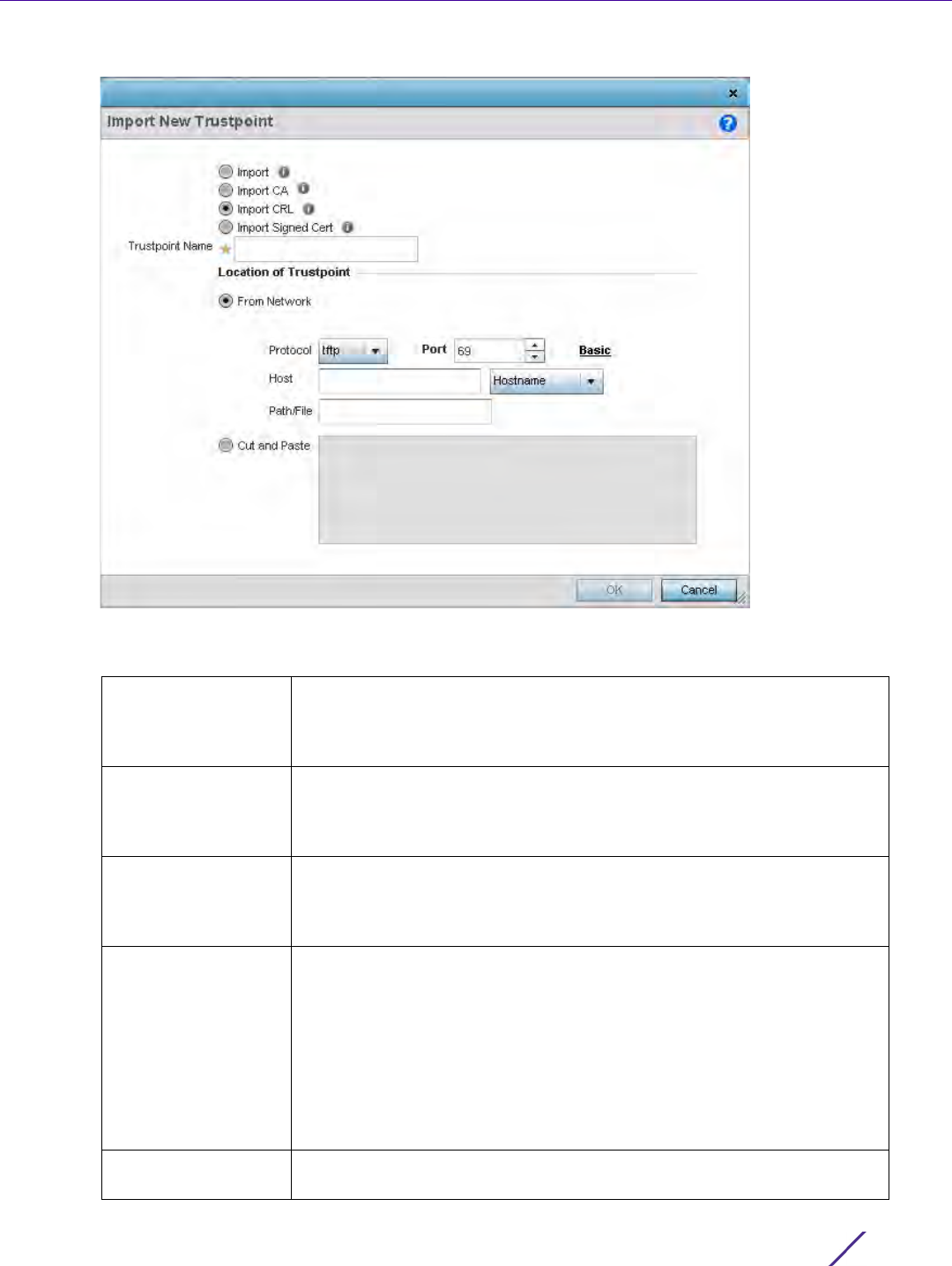
Device Configuration
Wireless Controller and Service Platform System Reference Guide 5 - 17
Figure 5-9 Certificate Management - Import CRL screen
11 Define the following configuration parameters required for the Import of the CRL
Trustpoint Name Enter the 32 character maximum name assigned to the target trustpoint
signing the certificate. A trustpoint represents a CA/identity pair
containing the identity of the CA, CA-specific configuration parameters,
and an association with an enrolled identity certificate.
From Network Select the From Network radio button to provide network address
information to the location of the target CRL. The number of additional
fields that populate the screen is also dependent on the selected protocol.
This is the default setting.
URL Provide the complete URL to the location of the CRL. If needed, select
Advanced to expand the dialog to display network address information to
the location of the CRL. The number of additional fields that populate the
screen is also dependent on the selected protocol.
Protocol Select the protocol used for importing the CRL. Available options include:
tftp
ftp
sftp
http
cf
usb1-4
Port Use the spinner control to set the port. This option is not valid for cf and
usb1-4.
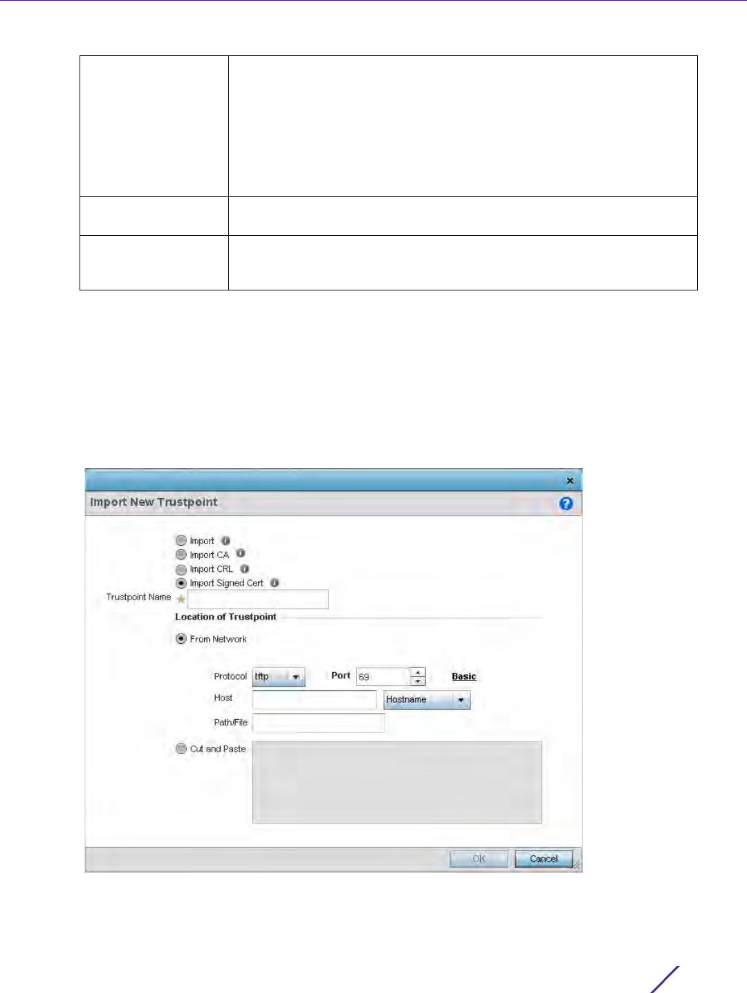
Device Configuration
Wireless Controller and Service Platform System Reference Guide 5 - 18
12 Select OK to import the CRL. Select Cancel to revert the screen to its last saved configuration.
13 To import a signed certificate, select the Import Signed Cert button from the Certificate Management screen.
Signed certificates (or root certificates) avoid the use of public or private CAs. A self-signed certificate is an
identity certificate signed by its own creator, thus the certificate creator also signs off on its legitimacy. The
lack of mistakes or corruption in the issuance of self signed certificates is central.
Self-signed certificates cannot be revoked which may allow an attacker who has already gained access to
monitor and inject data into a connection to spoof an identity if a private key has been compromised. However,
CAs have the ability to revoke a compromised certificate, preventing its further use.
Figure 5-10 Certificate Management - Import Signed Cert screen
Host Provide the hostname string or numeric IP address of the server used to
import the CRL. Hostnames cannot include an underscore character. This
option is not valid for cf and usb1-4.
Select IPv4 Address to use an IPv4 formatted address as the host. Select
IPv6 Address to use an IPv6 formatted address as the host. IPV6 provides
enhanced identification and location information for computers on
networks routing traffic across the Internet. IPv6 addresses are composed
of eight groups of four hexadecimal digits separated by colons.
Path/File Specify the path to the CRL file. Enter the complete relative path to the
file on the server.
Cut and Paste Select the Cut and Paste radio button to simply copy an existing CRL into
the cut and paste field. When pasting, no additional network address
information is required.

Device Configuration
Wireless Controller and Service Platform System Reference Guide 5 - 19
14 Define the following parameters required for the Import of the CA certificate:
15 Select OK to import the signed certificate. Select Cancel to revert the screen to its last saved configuration.
16 To optionally export a trustpoint to a remote location, select the Export button from the Certificate
Management screen.
Once a certificate has been generated on the controller or service platform’s authentication server, export the
self signed certificate. A digital CA certificate is different from a self signed certificate. The CA certificate
contains the public and private key pairs. The self certificate only contains a public key. Export the self
certificate for publication on a Web server or file server for certificate deployment or export it in to an active
directory group policy for automatic root certificate deployment.
Certificate Name Enter the 32 character maximum trustpoint name with which the
certificate should be associated.
From Network Select the From Network radio button to provide network address
information to the location of the signed certificate. The number of
additional fields that populate the screen is dependent on the selected
protocol. From Network is the default setting.
URL Provide the complete URL to the location of the signed certificate. If
needed, select Advanced to expand the dialog to display network address
information to the location of the signed certificate. The number of
additional fields populating the screen is dependent on the selected
protocol.
Protocol Select the protocol for importing the signed certificate. Available options
include:
tftp
ftp
sftp
http
cf
usb1-4
Port Use the spinner control to set the port. This option is not valid for cf and
usb1-4.
Host Provide the hostname string or numeric IP address of the server used to
import the signed certificate. Hostnames cannot include an underscore
character. This option is not valid for cf and
usb1-4.
Select IPv4 Address to use an IPv4 formatted address as the host. Select
IPv6 Address to use an IPv6 formatted address as the host. IPV6 provides
enhanced identification and location information for computers on
networks routing traffic across the Internet. IPv6 addresses are composed
of eight groups of four hexadecimal digits separated by colons.
Path/File Specify the path to the signed certificate file. Enter the complete relative
path to the file on the server.
Cut and Paste Select the Cut and Paste radio button to simply copy an existing
certificate into the cut and paste field. When pasting, no additional
network address information is required.
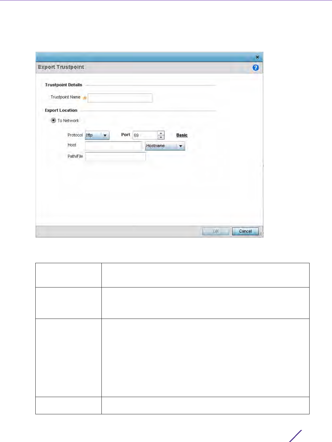
Device Configuration
Wireless Controller and Service Platform System Reference Guide 5 - 20
17 Additionally export the key to a redundant RADIUS server so it can be imported without generating a second
key. If there’s more than one RADIUS authentication server, export the certificate and don’t generate a second
key unless you want to deploy two root certificates.
Figure 5-11 Certificate Management - Export Trustpoint screen
18 Define the following configuration parameters required for the Export of the trustpoint.
Trustpoint Name Enter the 32 character maximum name assigned to the trustpoint. The
trustpoint signing the certificate can be a certificate authority, corporation
or individual.
URL Provide the complete URL to the location of the trustpoint. If needed,
select Advanced to expand the dialog to display network address
information to the location of the trustpoint. The number of additional
fields that populate the screen is dependent on the selected protocol.
Protocol Select the protocol used for exporting the target trustpoint. Available
options include:
tftp
ftp
sftp
http
cf
usb1-4
Port Use the spinner control to set the port. This option is not valid for cf and
usb1-4.

Device Configuration
Wireless Controller and Service Platform System Reference Guide 5 - 21
19 Select OK to export the defined trustpoint. Select Cancel to revert the screen to its last saved configuration.
20 To optionally delete a trustpoint, select the Delete button from within the Certificate Management screen.
Provide the trustpoint name within the Delete Trustpoint screen and optionally select Delete RSA Key to
remove the RSA key along with the trustpoint. Select OK to proceed with the deletion, or Cancel to revert to
the Certificate Management screen
5.2.2.2 RSA Key Management
Assigning Certificates
Refer to the RSA Keys screen to review existing RSA key configurations that have been applied to managed
devices. If an existing key does not meet the needs of a pending certificate request, generate a new key or import/
export an existing key to and from a remote location.
Rivest, Shamir, and Adleman (RSA) is an algorithm for public key cryptography. It’s an algorithm that can be used
for certificate signing and encryption. When a device trustpoint is created, the RSA key is the private key used
with the trustpoint.
To review existing device RSA key configurations, generate additional keys or import/export keys to and from
remote locations:
1 Select the Launch Manager button from either the SSH RSA Key, RADIUS Certificate Authority or RADIUS
Server Certificate parameters (within the Certificate Management screen).
2Select
RSA Keys from the Certificate Management screen.
Host Provide the hostname string or numeric IP address of the server used to
export the trustpoint. Hostnames cannot include an underscore character.
This option is not valid for cf and usb1-4.
Select IPv4 Address to use an IPv4 formatted address as the host. Select
IPv6 Address to use an IPv6 formatted address as the host. IPV6 provides
enhanced identification and location information for computers on
networks routing traffic across the Internet. IPv6 addresses are composed
of eight groups of four hexadecimal digits separated by colons.
Path/File Specify the path to the signed trustpoint file. Enter the complete relative
path to the file on the server.
Cut and Paste Select the Cut and Paste radio button to simply copy an existing
trustpoint into the cut and paste field. When pasting, no additional
network address information is required.
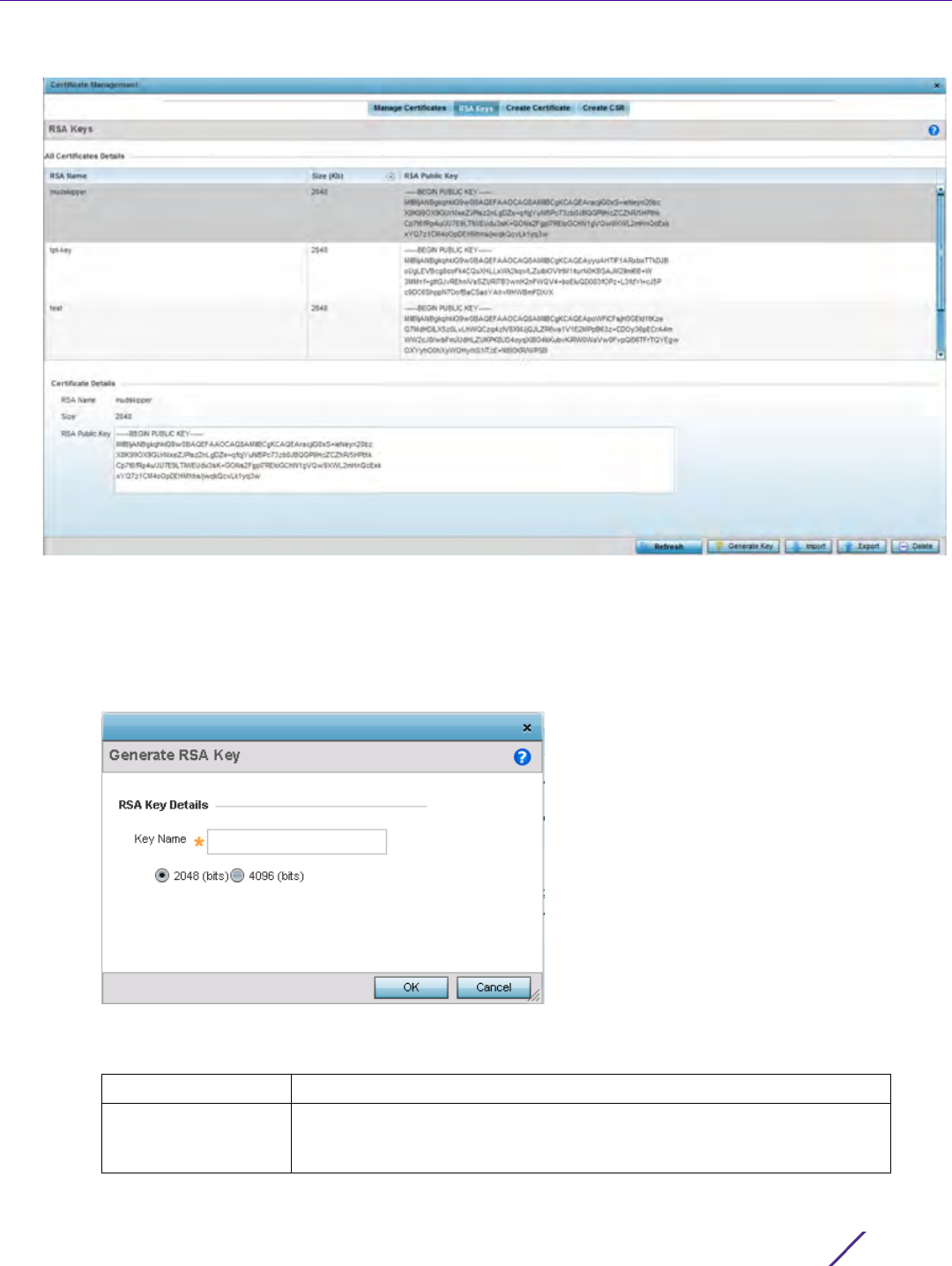
Device Configuration
Wireless Controller and Service Platform System Reference Guide 5 - 22
Figure 5-12 Certificate Management - RSA Keys screen
3 Select a listed device to review its current RSA key configuration.
Each key can have its size and character syntax displayed. Once reviewed, optionally generate a new RSA key,
import a key from a selected device, export a key to a remote location or delete a key from a selected device.
4Select
Generate Key to create a new key with a defined size.
Figure 5-13 Certificate Management - Generate RSA Keys screen
5 Define the following configuration parameters required for the Import of the key:
6Select
OK to generate the RSA key. Select Cancel to revert the screen to its last saved configuration.
Key Name Enter the 32 character maximum name assigned to the RSA key.
Key Size Set the size of the key as either 2048 (bits) or 4096 (bits). Leaving this
value at the default setting of 2048 is recommended to ensure optimum
functionality.
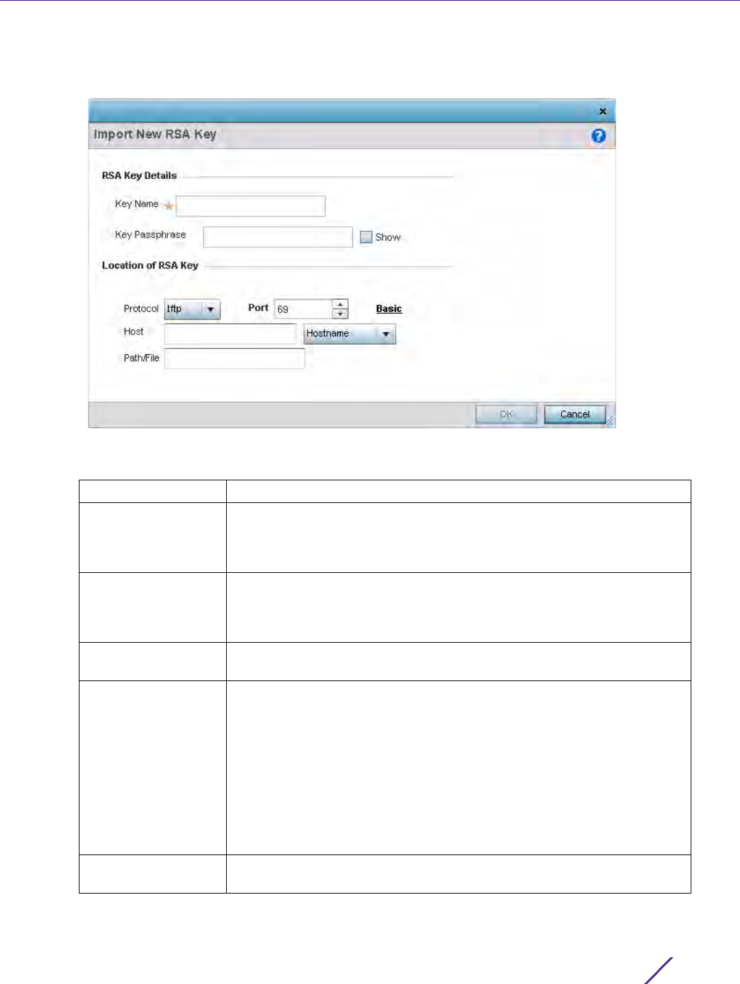
Device Configuration
Wireless Controller and Service Platform System Reference Guide 5 - 23
7 To optionally import a CA certificate, select the Import button from the Certificate Management > RSA Keys
screen.
Figure 5-14 Certificate Management - Import New RSA Key screen
8 Define the following parameters required for the Import of the RSA key:
Key Name Enter the 32 character maximum name assigned to identify the RSA key.
Key Passphrase Define the key used by both the controller or service platform and the
server (or repository) of the target RSA key. Select the Show to expose
the actual characters used in the passphrase. Leaving the Show
unselected displays the passphrase as a series of asterisks “*”.
URL Provide the complete URL to the location of the RSA key. If needed,
select Advanced to expand the dialog to display network address
information to the location of the target key. The number of additional
fields that populate the screen is dependent on the selected protocol.
Advanced or Basic Select either the Advanced or Basic link to switch between a basic URL
and an advanced location to specify key location.
Protocol Select the protocol used for importing the target key. Available options
include:
tftp
ftp
sftp
http
cf
usb1-4
Port Use the spinner control to set the port. This option is not valid for cf and
usb1-4.
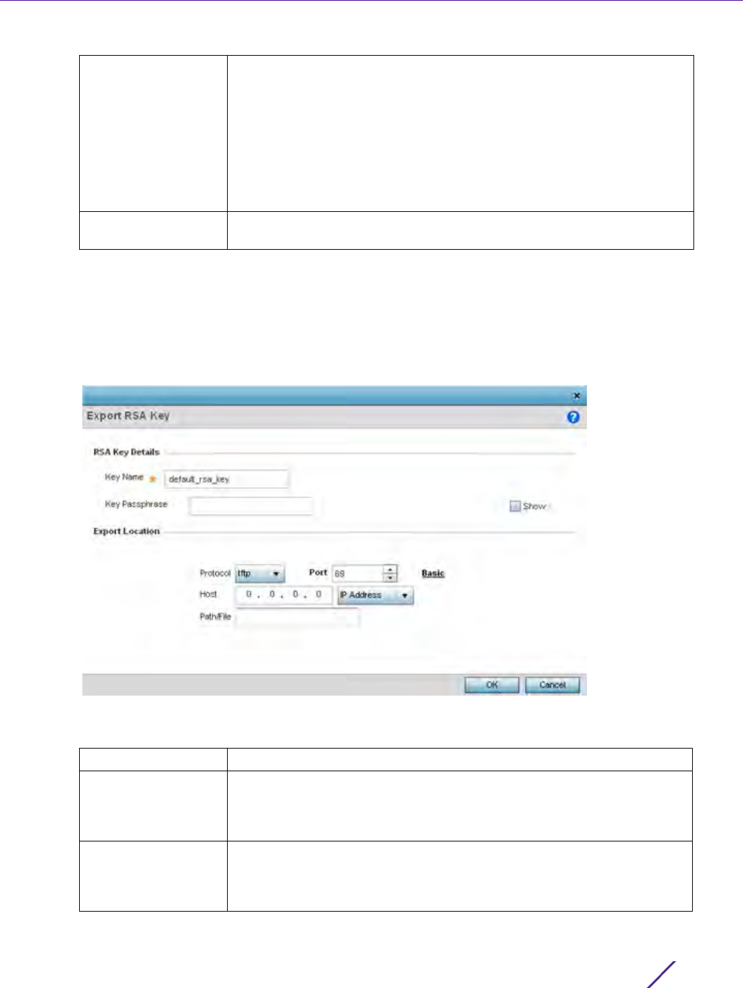
Device Configuration
Wireless Controller and Service Platform System Reference Guide 5 - 24
9Select
OK to import the defined RSA key. Select Cancel to revert the screen to its last saved configuration.
10 To optionally export a RSA key to a remote location, select the Export button from the Certificate Management
> RSA Keys screen.
Export the key to a redundant RADIUS server to import it without generating a second key. If there’s more
than one RADIUS authentication server, export the certificate and don’t generate a second key unless you want
to deploy two root certificates.
Figure 5-15 Certificate Management - Export RSA Key screen
11 Define the following configuration parameters required for the Export of the RSA key.
Host Provide a text string hostname or numeric IP address of the server used
to import the RSA key. Hostnames cannot include an underscore
character. This option is not valid for cf and
usb1-4.
Select IPv4 Address to use an IPv4 formatted address as the host. Select
IPv6 Address to use an IPv6 formatted address as the host. IPV6 provides
enhanced identification and location information for computers on
networks routing traffic across the Internet. IPv6 addresses are composed
of eight groups of four hexadecimal digits separated by colons.
Path/File Specify the path to the RSA key. Enter the complete relative path to the
key on the server.
Key Name Enter the 32 character maximum name assigned to the RSA key.
Key Passphrase Define the key passphrase used by both the controller or service platform
and the server. Select Show to expose the actual characters used in the
passphrase. Leaving the Show unselected displays the passphrase as a
series of asterisks “*”.
URL Provide the complete URL to the location of the key. If needed, select
Advanced to expand the dialog to display network address information to
the location of the target key. The number of additional fields that
populate the screen is dependent on the selected protocol.

Device Configuration
Wireless Controller and Service Platform System Reference Guide 5 - 25
12 Select OK to export the defined RSA key. Select Cancel to revert the screen to its last saved configuration.
13 To optionally delete a key, select the Delete button from within the Certificate Management > RSA Keys screen.
Provide the key name within the Delete RSA Key screen and select Delete Certificates to remove the certificate.
Select OK to proceed with the deletion, or Cancel to revert back to the Certificate Management screen.
5.2.2.3 Certificate Creation
Assigning Certificates
The Certificate Management screen provides the facility for creating new self-signed certificates. Self signed
certificates (often referred to as root certificates) do not use public or private CAs. A self signed certificate is a
certificate signed by its own creator, with the certificate creator responsible for its legitimacy.
To create a self-signed certificate that can be applied to a managed device:
1 Select the Launch Manager button from either the SSH RSA Key, RADIUS Certificate Authority or RADIUS
Server Certificate parameters (within the Certificate Management screen).
2Select
Create Certificate from the upper, left-hand, side of the Certificate Management screen.
Protocol Select the protocol used for exporting the RSA key. Available options
include:
tftp
ftp
sftp
http
cf
usb1-4
Port Use the spinner control to set the port. This option is not valid for cf and
usb1-4.
Host Provide a text string hostname or numeric IP address of the server used
to export the RSA key. Hostnames cannot include an underscore
character. This option is not valid for cf and
usb1-4.
Select IPv4 Address to use an IPv4 formatted address as the host. Select
IPv6 Address to use an IPv6 formatted address as the host. IPV6 provides
enhanced identification and location information for computers on
networks routing traffic across the Internet. IPv6 addresses are composed
of eight groups of four hexadecimal digits separated by colons.
Path / File Specify the path to the key. Enter the complete relative path to the key
on the server.
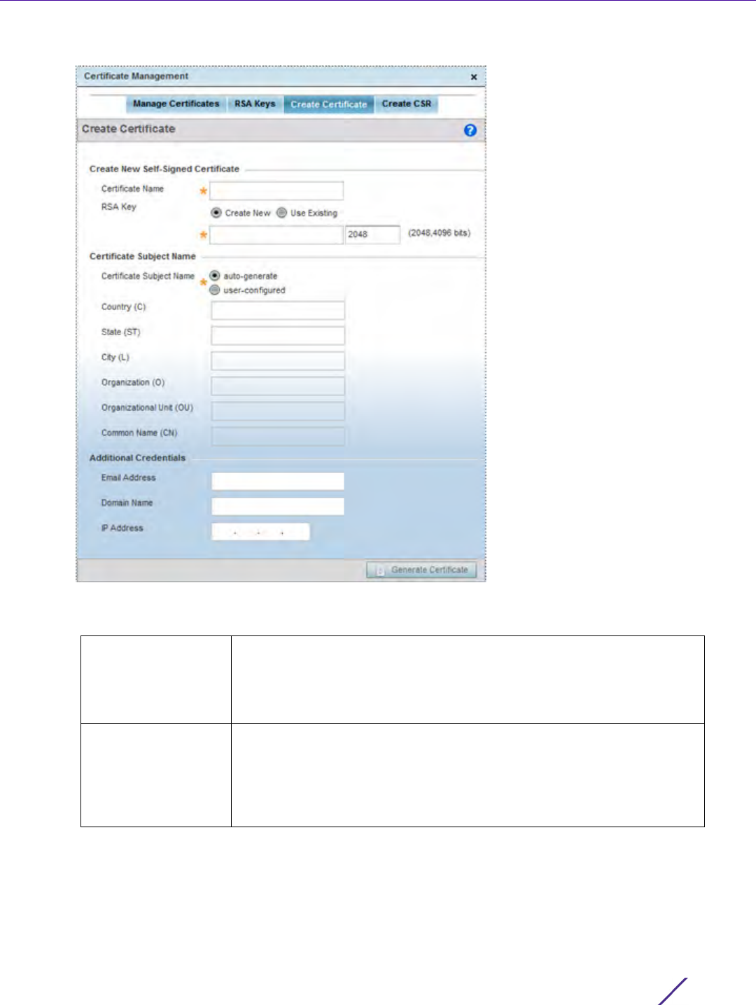
Device Configuration
Wireless Controller and Service Platform System Reference Guide 5 - 26
Figure 5-16 Certificate Management - Create Certificate screen
3 Define the following configuration parameters required to Create New Self-Signed Certificate:
Certificate Name Enter the 32 character maximum name assigned to identify the name of
the trustpoint associated with the certificate. A trustpoint represents a
CA/identity pair containing the identity of the CA, CA-specific
configuration parameters, and an association with an enrolled identity
certificate.
RSA Key Select a radio button and use the drop-down menu to set the key used
by both the controller or service platform and the server (or repository)
of the target RSA key. Optionally select Create New and enter a 32
character name used to identify the RSA key. Set the size of the key to
either 2,048 or 4,096 bits. Leaving this value at the default setting of
2,048 is recommended to ensure optimum functionality.

Device Configuration
Wireless Controller and Service Platform System Reference Guide 5 - 27
4 Set the following Certificate Subject Name parameters required for the creation of the certificate:
5 Select the following Additional Credentials required for the generation of the self signed certificate:
6 Select the Generate Certificate button at the bottom of the Certificate Management > Create Certificate screen
to produce the certificate.
5.2.2.4 Generating a Certificate Signing Request
Assigning Certificates
A certificate signing request (CSR) is a request to a certificate authority to apply for a digital identity certificate.
The CSR is a block of encrypted text generated on the server the certificate is used on. It contains the organization
name, common name (domain name), locality and country.
A RSA key must be either created or applied to the certificate request before the certificate can be generated. A
private key is not included in the CSR, but is used to digitally sign the completed request. The certificate created
with a particular CSR only works with the private key generated with it. If the private key is lost, the certificate is
no longer functional.The CSR can be accompanied by other identity credentials required by the certificate
authority, and the certificate authority maintains the right to contact the applicant for additional information.
If the request is successful, the CA sends an identity certificate digitally signed with the private key of the CA.
To create a CSR:
Certificate Subject
Name
Select either auto-generate to automatically create the certificate's
subject credentials or user-configurable to manually enter the credentials
of the self signed certificate. The default setting is auto-generate.
Country (C) Define the Country used in the certificate. The field can be modified by
the user to other values. This is a required field and must not exceed 2
characters.
State (ST) Enter a State/Prov. for the state or province name used in the certificate.
This is a required field.
City (L) Enter a City to represent the city used in the certificate. This is a required
field.
Organization (O) Define an Organization for the organization represented in the certificate.
This is a required field.
Organizational Unit
(OU)
Enter an Org. Unit for the organization unit represented in the certificate.
This is a required field.
Common Name (CN) If there’s a common name (IP address) for the organizational unit issuing
the certificate, enter it here.
Email Address Provide an Email Address used as the contact address for issues relating
to this certificate request.
Domain Name Enter a fully qualified domain name (FQDN) is an unambiguous domain
name that specifies the node's position in the DNS tree hierarchy
absolutely. To distinguish an FQDN from a regular domain name, a
trailing period is added. For example, somehost.example.com. An FQDN
differs from a regular domain name by its absoluteness, since a suffix is
not added.
IP Address Specify the IP address used as the destination for certificate
requests.Only IPv4 formatted IP addresses are permitted, not IPv6
formatted addresses.
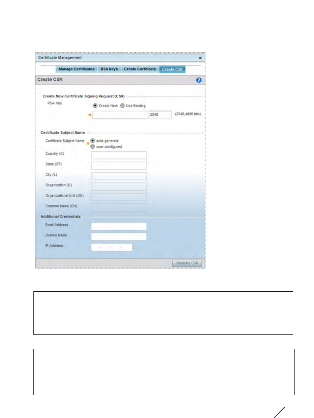
Device Configuration
Wireless Controller and Service Platform System Reference Guide 5 - 28
1 Select the Launch Manager button from either the SSH RSA Key, RADIUS Certificate Authority or RADIUS
Server Certificate parameters (within the Certificate Management screen).
2Select
Create CSR from the upper, left-hand, side of the Certificate Management screen.
Figure 5-17 Certificate Management - Create CSR screen
3 Define the following configuration parameters required to Create New Certificate Signing Request (CSR):
4 Set the following Certificate Subject Name parameters required for the creation of the certificate:
RSA Key Select a radio button and use the drop-down menu to set the key used by
both the controller or service platform and the server (or repository) of
the target RSA key. Optionally select Create New to use new RSA key and
provide a 32 character name used to identify the RSA key. Set the size of
the key to either 2,048 or 4,096 bits. Leaving this value at the default
setting of 2,048 is recommended to ensure optimum functionality.
Certificate Subject
Name
Select either the auto-generate radio button to automatically create the
certificate's subject credentials or user-configurable to manually enter the
credentials of the self signed certificate. The default setting is auto-
generate.
Country (C) Define the Country used in the CSR. The field can be modified by the user
to other values. This is a required field and must not exceed 2 characters.
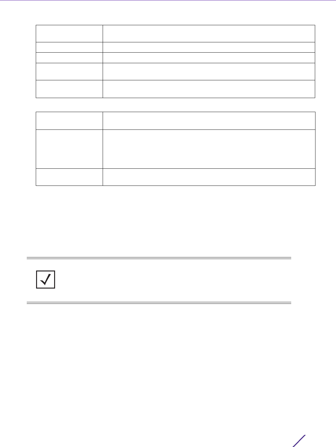
Device Configuration
Wireless Controller and Service Platform System Reference Guide 5 - 29
5 Select the following Additional Credentials required for the generation of the CSR:
6 Select the Generate CSR button to produce the CSR.
5.2.3 Port Mirroring (NX4524 and NX6524 Service Platforms only)
Basic Device Configuration
NX4524 and NX6524 model service platforms have the ability to mirror data packets transmitted or received on
any of their GE ports (GE port 1 - 24). Both transmit and receive packets can be mirrored from a source to a
destination port as needed to provide traditional spanning functionality on the 24 GE ports.
To set a NX4524 or NX6524 service platform port mirror configuration:
1 Select the Configuration tab from the Web UI.
2Select
Devices from the Configuration tab.
The Device Configuration screen displays a list of managed devices or peer controllers, service platforms or
Access Points.
3 Select a target device (by double-clicking it) from amongst those displayed within the Device Configuration
screen.
Devices can also be selected directly from the Device Browser in the lower, left-hand, side of the UI.
4Select
Mirroring from the Device menu options.
State (ST) Enter a State/Prov. for the state or province name represented in the CSR.
This is a required field.
City (L) Enter a City represented in the CSR. This is a required field.
Organization (O) Define the Organization represented in the CSR. This is a required field.
Organizational Unit
(OU)
Enter the Org. Unit represented in the CSR. This is a required field.
Common Name (CN) If there’s a common name (IP address) for the organizational unit issuing
the certificate, enter it here.
Email Address Provide an email address used as the contact address for issues relating to
this CSR.
Domain Name Enter a fully qualified domain name (FQDN) is an unambiguous domain
name that specifies the node's position in the DNS tree hierarchy
absolutely. To distinguish an FQDN from a regular domain name, a trailing
period is added. ex: somehost.example.com. An FQDN differs from a
regular domain name by its absoluteness; as a suffix is not added.
IP Address Specify the IP address used as the destination for certificate requests.Only
IPv4 formatted IP addresses are permitted, not IPv6 formatted addresses.
NOTE: Port mirroring is not supported on NX4500 or NX6500 models, as they only
utilize GE ports 1 - 2. Additionally, port mirroring is not supported on uplink (up)
ports or wired ports on any controller or service platform model.
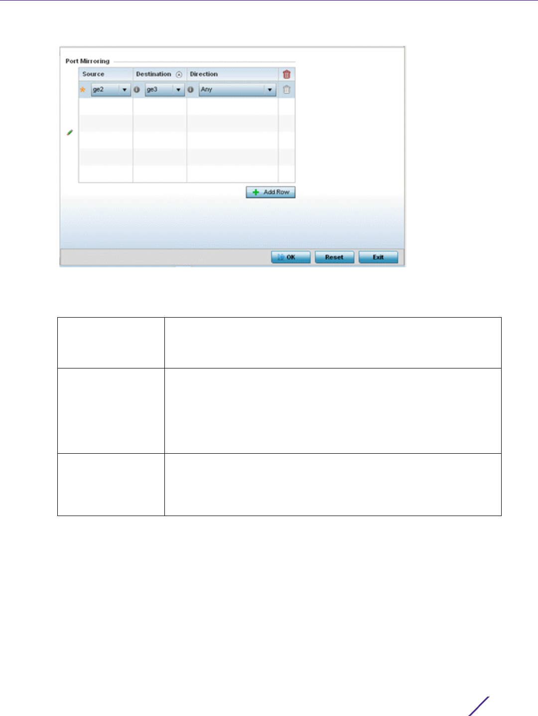
Device Configuration
Wireless Controller and Service Platform System Reference Guide 5 - 30
Figure 5-18 Port Mirroring screen
5 Set the following Port Mirroring values to define the ports and directions data is spanned on the NX4524 or
NX6524 model service platform:
6Select
+ Add Row to add different sources, destinations and directions for additional GE port spanning
configurations.
7Select
OK to save the changes made to the NX4524 or NX6524 port mirroring configuration. Selecting Reset
reverts the screen to its last saved configuration.
5.2.4 Wired 802.1x Configuration
Basic Device Configuration
802.1X is an IEEE standard for media-level (Layer 2) access control, providing the capability to permit or deny
connectivity based on user or device identity. 802.1X allows port based access using authentication. An 802.1X
enabled port can be dynamically enabled or disabled depending on user identity or device connection.
Source Select the GE port (1 - 24) used as the data source to span packets to the
selected destination port. The packets spanned from the selected source
to the destination depend on whether Inbound, Outbound or Any is
selected as the direction. A source port cannot be a destination port.
Destination Select the GE port (1 - 24) used as the port destination to span packets
from the selected source. The destination port serves as a duplicate
image of the source port and can be used to send packets to a network
diagnostic without disrupting the behavior on the original port. The
destination port transmits only mirrored traffic and does not forward
received traffic. Additionally, address learning is disabled on the
destination port.
Direction Define the direction data packets are spanned from the selected source
to the defined destination. Packets spanned from the source to the
destination depend on whether Inbound (received packets only),
Outbound (transmitted packets only) or Any (packets in either direction)
is selected.
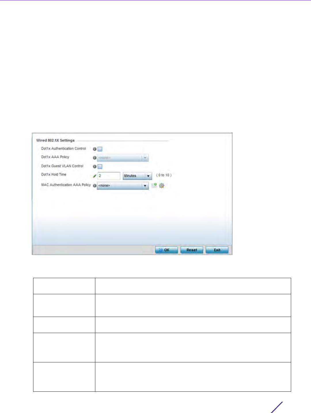
Device Configuration
Wireless Controller and Service Platform System Reference Guide 5 - 31
Before authentication, the endpoint is unknown, and traffic is blocked. Upon authentication, the endpoint is known
and traffic is allowed. The controller or service platform uses source MAC filtering to ensure only the authenticated
endpoint is allowed to send traffic.
To configure a device’s wired 802.1x configuration:
1 Select the Configuration tab from the Web UI.
2Select
Devices from the Configuration tab.
The Device Configuration screen displays a list of managed devices or peer controllers, service platforms or
Access Points.
3 Select a device (by double-clicking it) from amongst those displayed within the Device Configuration screen.
Devices can also be selected directly from the Device Browser in the lower, left-hand, side of the UI.
4Select
Wired 802.1x from the Device menu options.
Figure 5-19 Device Wired 802.1x screen
5Review the Wired 802.1x Settings area to configure the following parameters:
Dot1x Authentication
Control
Select this option to globally enable 802.1x authentication. 802.1x
authentication is disabled by default.
Dot1x AAA Policy Use the drop-down menu to select a AAA policy to associate with wired
802.1x traffic. If a suitable AAA policy does not exist, select the Create
icon to create a new policy or the Edit icon to modify an existing policy.
Dot1x Guest VLAN
Control
Select this option to globally enable the use of 802.1x guest VLANs.
Dot1x Hold Time Set a hold time value (after the last hello packet) in either Seconds (0 -
600) or Minutes (0 - 10). When exceeded, the controller’s 802.1X enabled
port and its destination end-point connection is defined as lost and the
connection must be re-established.
MAC Authentication
AAA Policy
Use the drop-down menu to select an AAA authentication policy for MAC
address authentication. If a suitable MAC AAA policy does not exist, click
the Create icon to create a new policy or the Edit icon to modify an
existing policy.

Device Configuration
Wireless Controller and Service Platform System Reference Guide 5 - 32
6Select
OK to save the changes made to the 802.1x configurations. Selecting Reset reverts the screen to its last
saved configuration.
5.2.5 RF Domain Overrides
Basic Device Configuration
Use RF Domain Overrides to define configurations overriding the configuration set by the target device’s original
RF Domain assignment.
RF Domains allow administrators to assign configuration data to multiple devices deployed in a common coverage
area (floor, building or site). In such instances, there’s many configuration attributes these devices share, since their
general client support roles are quite similar. However, device configurations may need periodic refinement from
their original RF Domain administered design.
A controller or service platform configuration contains (at a minimum) one default RF Domain, but can optionally
use additional user defined RF Domains:
•Default RF Domain - Automatically assigned to each controller, service platform and associated Access Points
by default. A default RF Domain is unique to a specific model.
•User Defined RF Domains - Created by administrators and manually assigned to individual controllers, service
platforms or Access Points, but can be automatically assigned to Access Points using adoption policies.
Each controller, service platform and Access Point is assigned one RF Domain at a time. However, a user defined
RF Domain can be assigned to multiple devices as required. User defined RF Domains can be manually assigned or
automatically assigned to Access Points using an auto provisioning policy. The more devices assigned a single RF
Domain, the greater the likelihood one of the device’s configurations will require an override deviating that device’s
configuration from the original RF Domain assignment shared by the others.
To review the RF Domain’s original configuration requirements and the options available for a target device, refer
to Managing RF Domains on page 9-2.
To define a device’s RF Domain override configuration:
1 Select the Configuration tab from the Web UI.
2Select
Devices from the Configuration tab.
The Device Configuration screen displays a list of managed devices or peer controllers, service platforms or
Access Points.
3 Select a device (by double-clicking it) from amongst those displayed within the Device Configuration screen.
Devices can also be selected directly from the Device Browser in the lower, left-hand, side of the UI.
4Expand the RF Domain Overrides menu option to display its sub-menu options.
5Select
RF Domain.
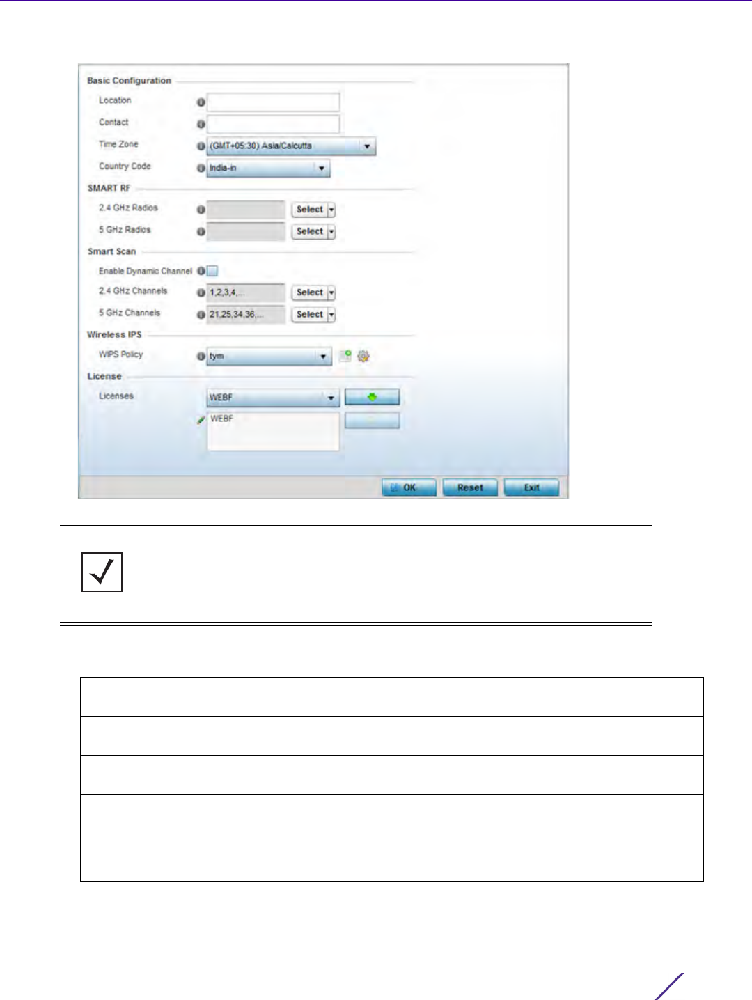
Device Configuration
Wireless Controller and Service Platform System Reference Guide 5 - 33
Figure 5-20 RF Domain Overrides - Basic Configuration screen
6 Refer to the Basic Configuration field to review the basic settings defined for the target device’s RF Domain
configuration, and optionally assign/remove overrides to and from specific parameters.
NOTE: A blue override icon (to the left of a parameter) defines the parameter as
having an override applied. To remove an override go to the Basic Configuration
section of the device and click the Clear Overrides button. This removes all
overrides from the device.
Location Provide the 64 character maximum deployment location set for the
controller or service platform as part of its RF Domain configuration.
Contact Enter the 64 character maximum administrative contact for the controller
or service platform as part of its RF Domain configuration.
Time Zone Set the time zone utilized by the selected device as part of its RF Domain
configuration.
Country Code Set the country code utilized by the device as part of its RF Domain
configuration. Selecting the correct country is central to legal operation.
Each country has its own regulatory restrictions concerning
electromagnetic emissions and the maximum RF signal strength that can
be transmitted.

Device Configuration
Wireless Controller and Service Platform System Reference Guide 5 - 34
7 Refer to the Smart RF section to configure Smart RF policy and dynamic channel settings.
8 Refer to the Smart Scan section to configure Smart RF policy and dynamic channel settings.
9Use the WIPS Policy drop-down menu to apply a WIPS policy to the RF Domain.
The Wireless Intrusion Protection System (WIPS) provides continuous protection against wireless threats and
act as an additional layer of security complementing wireless VPNs and encryption and authentication policies.
Controllers and service platforms support WIPS through the use of dedicated sensor devices, designed to
actively detect and locate unauthorized AP devices. After detection, they use mitigation techniques to block
devices using manual termination, air lockdown or port suppression.
Select the Create icon to define a new WIPS policy that can be applied to the RF Domain, or select the Edit
icon to modify or override an existing WIPS policy.
For an overview of WIPS and instructions on how to create a WIPS policy that can be used with a RF Domain,
see Intrusion Prevention on page 10-51.
10 Use the Licenses drop-down menu to obtain and leverage feature licenses from RF Domain member devices.
11 Select OK to save the changes and overrides made to the RF Domain configuration. Selecting Reset reverts the
screen to its last saved configuration.
12 Select Sensor from within the expanded RF Domain Overrides menu to define ADSP server credentials for
WiNG controller or service platform data exchanges.
Controllers and service platforms support dedicated sensor devices, designed to actively detect and locate
unauthorized AP devices. After detection, they use mitigation techniques to block devices using manual
termination, air lockdown or port suppression.
2.4 GHz Radios Select an override group of channels Smart RF can use for channel
compensation adjustments in the 2.4 GHz band.
5 GHz Radios Select an override group of channels Smart RF can use for channel
compensation adjustments in the 5 GHz band.
Enable Dynamic
Channel
Select this option to enable dynamic channel switching for Smart RF
radios.
2.4 GHz Channels Select legal channels (device radios transmit in specific channels unique
to their country of operation) from the drop-down menu for 2.4GHz
Smart RF radios.
5 GHz Channels Select legal channels (device radios transmit in specific channels unique
to their country of operation) from the drop-down menu for 5GHz Smart
RF radios.
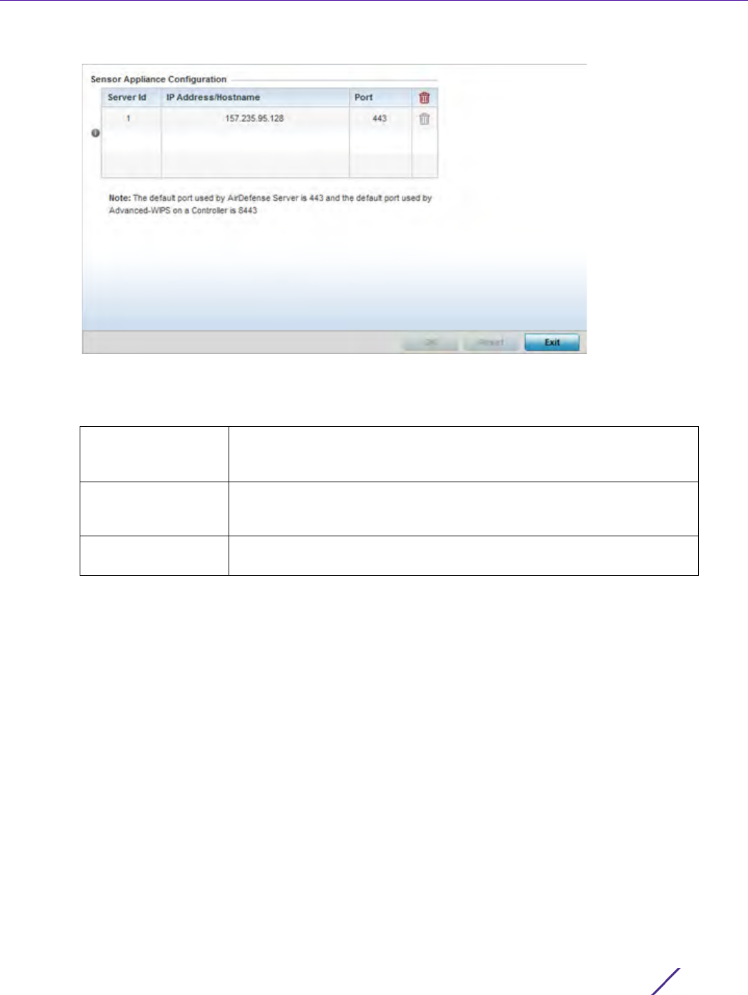
Device Configuration
Wireless Controller and Service Platform System Reference Guide 5 - 35
Figure 5-21 RF Domain - Sensor screen
13 Select the + Add Row button to populate the Server Appliance Configuration field with up to three rows for
ADSP server credentials:
14 Select OK to save the changes to the ADSP appliance sensor configuration, or select Reset to revert to the last
saved configuration.
15 Select Client Name from within the expanded RF Domain Overrides:
Server Id Use the spinner control to assign a numerical ID for up to three WIPS
server resources. The server with the lowest defined ID is the first reached
by the controller or service platform. The default ID is 1.
IP Address/Hostname Provide the numerical (non DNS) IP address or hostname of each server
used as a WIPS sensor server by RF Domain member devices. A
hostname cannot exceed 64 characters or contain an underscore.
Port Use the spinner control to specify the port of each WIPS sensor server
utilized by RF member devices. The default port is 443.
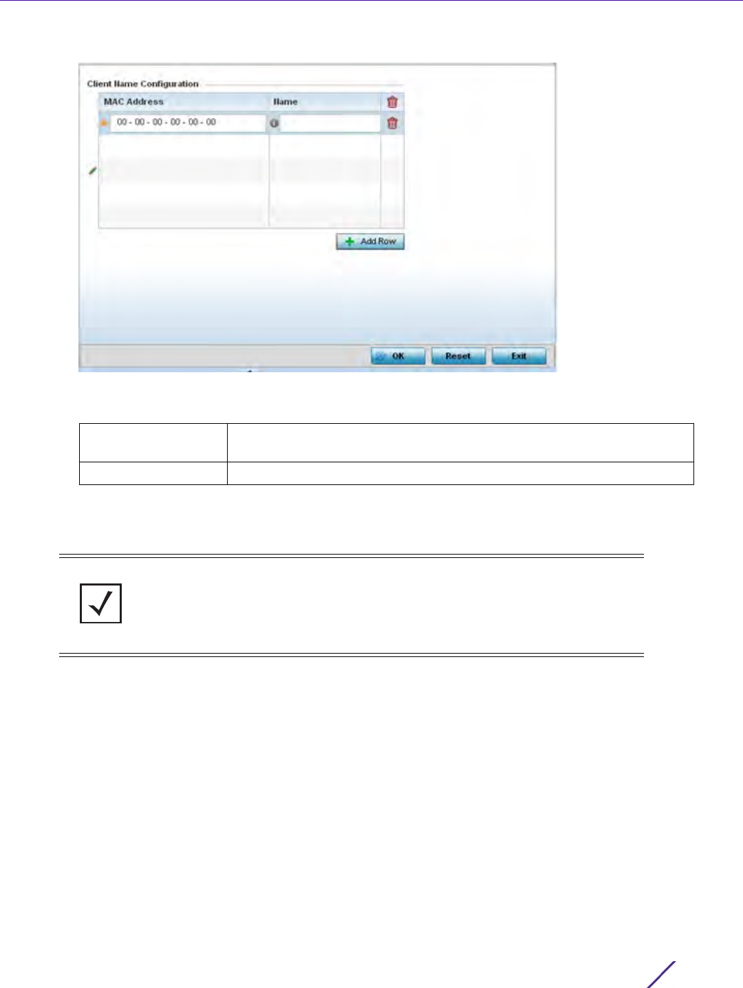
Device Configuration
Wireless Controller and Service Platform System Reference Guide 5 - 36
Figure 5-22 Client Name screen
16 Click + Add Row to add client name information to the table.
17 Select OK to save the changes and overrides made to the Client Name Configuration. Selecting Reset reverts
the screen to its last saved configuration.
18 Select WLAN Override from within the expanded RF Domain Overrides menu.
MAC Address Enter the MAC address of the device assigned a client name for controller,
service platform or Access Point management.
Name Enter the name assigned to this client.
NOTE: The WLAN Override option does not appear as a sub menu option under RF
Domain Overrides for either controllers or service platforms, just Access Points.
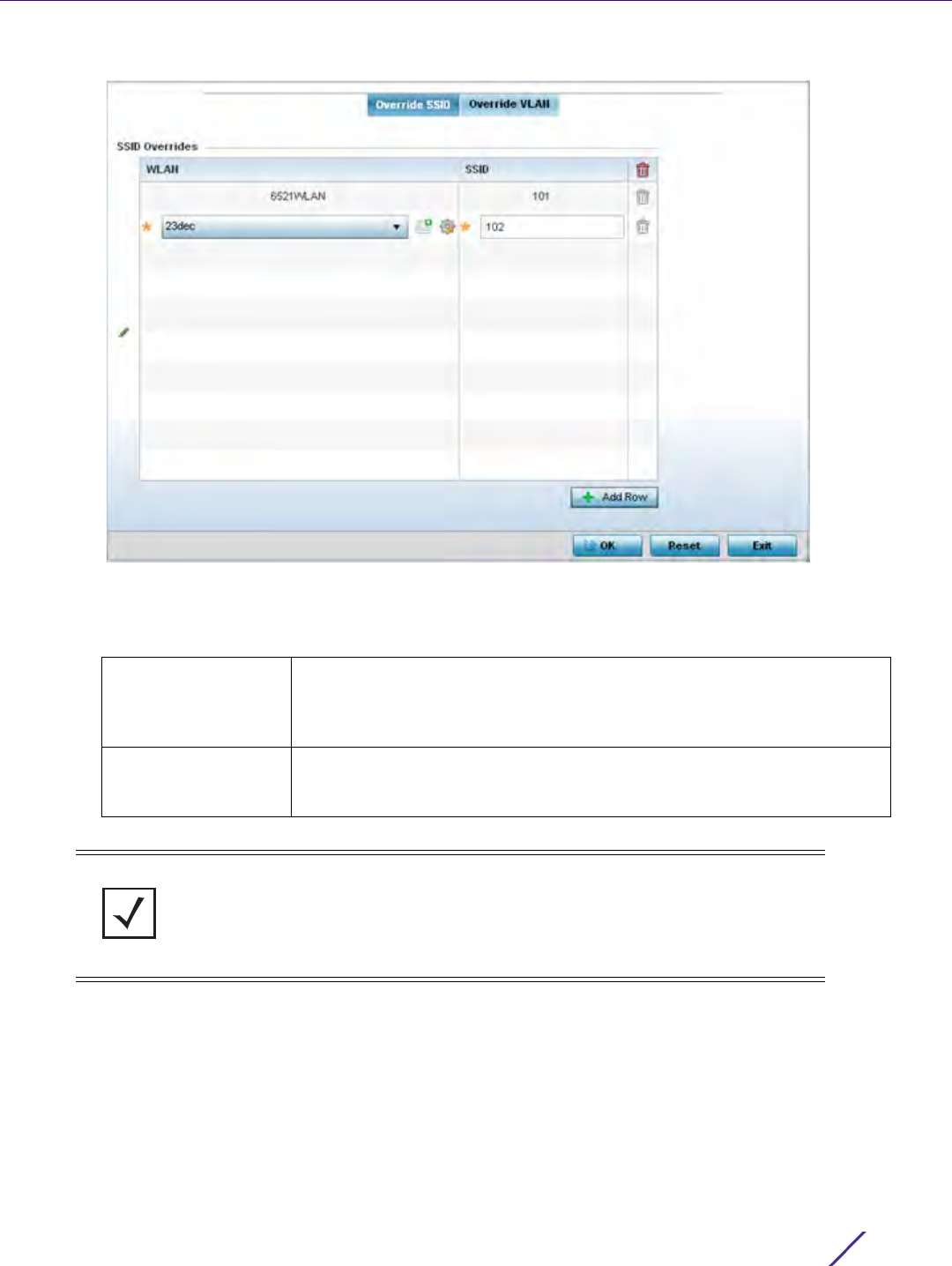
Device Configuration
Wireless Controller and Service Platform System Reference Guide 5 - 37
Figure 5-23 WLAN Override screen - Override SSID tab
The WLAN Override screen displays with the Override SSID tab displayed by default.
19 Optionally define up to 3 overrides for the listed WLAN SSID assignment:
20 Select the Add Row button as needed to add additional WLAN SSID overrides.
21 Select OK to save the changes and overrides. Selecting Reset reverts the screen to its last saved configuration.
22 Select the Override VLAN tab to review any VLAN assignment overrides that may have been or optionally add
or edit override configurations.
WLAN Optionally use the drop-down menu to change the WLAN assignment for
the listed Access Point. Select either the Create icon to define a new
WLAN configuration, or select the Edit icon to modify an existing WLAN
configuration.
SSID Optionally change the SSID associated with the WLAN. The WLAN name
is auto-generated using the SSID until changed (overridden). The
maximum number of characters used for the SSID is 32.
NOTE: A blue override icon (to the left of a parameter) defines the parameter as
having an override applied. To remove an override go to the Basic Configuration
section of the device and click the Clear Overrides button. This removes all
overrides from the device.
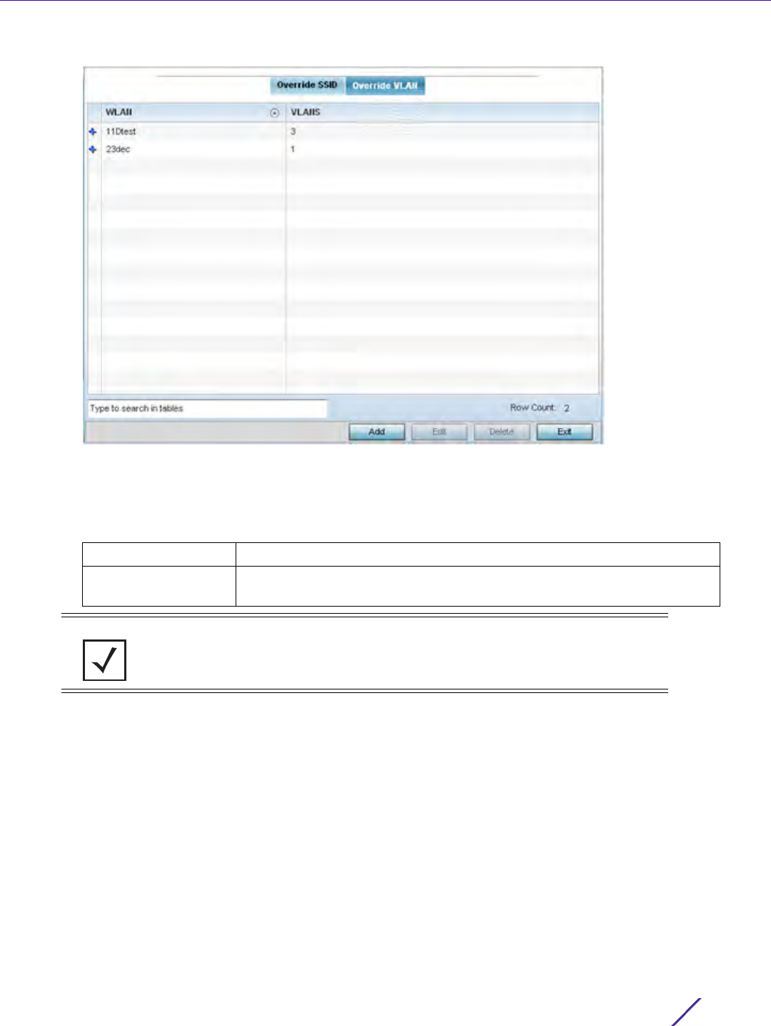
Device Configuration
Wireless Controller and Service Platform System Reference Guide 5 - 38
Figure 5-24 WLAN Override screen - Override VLAN tab
The Override VLAN tab displays VLANs assigned to the Access Point’s WLAN. Select Add to create a new
client limit for a specific WLAN and VLAN or Edit to modify an existing configuration.
23 Optionally define a VLAN’s wireless client limit override configuration.
24 Select OK to save the changes and overrides. Selecting Reset reverts the screen to its last saved configuration.
5.2.6 Profile Overrides
Basic Device Configuration
Profiles enable administrators to assign a common set of parameters and policies to controllers, service platforms
and Access Points. Profiles can be used to assign shared or unique network, wireless and security parameters to
wireless controllers and Access Points across a large, multi segment, site. The configuration parameters within a
profile are based on the hardware model the profile was created to support. Controllers and service platforms
support both default and user defined profiles implementing new features or updating existing parameters to
groups of devices. The central benefit of a profile is its ability to update devices collectively without having to
modify individual device configurations. Power and Adoption overrides apply specifically to Access Points, while
Cluster configuration overrides apply to only controller or service platform configurations.
VLANS Use the spinner control to set a virtual interface ID (1 - 4094).
Wireless Client Limit Use the spinner control to set the number of users permitted on the
VLAN. Set the value to 0 to have an unlimited number of users.
NOTE: A blue override icon (to the left of a parameter) defines the parameter as
having an override applied. To remove an override go to the Basic Configuration
section of the device and click the Clear Overrides button. This removes all
overrides from the device.
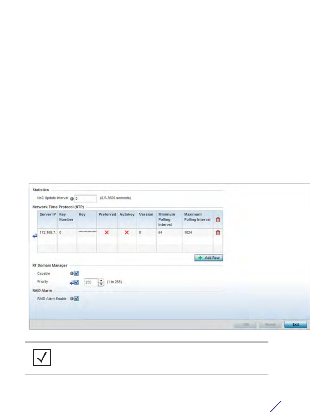
Device Configuration
Wireless Controller and Service Platform System Reference Guide 5 - 39
However, device profile configurations may need periodic refinement from their original administered design.
Consequently, a device profile could require modification from a profile configuration shared amongst numerous
devices deployed within a particular site.
Use Profile Overrides to define configurations overriding the parameters set by the target device’s original profile
assignment.
To review a profile’s original configuration requirements and the options available for a target device, refer to
General Profile Configuration on page 8-5.
To define a device’s general profile override configuration:
1 Select the Configuration tab from the Web UI.
2Select
Devices from the Configuration tab.
The Device Configuration screen displays a list of managed devices or peer controllers, service platforms or
Access Points.
3 Select a device (by double-clicking it) from amongst those displayed within the Device Configuration screen.
Devices can also be selected directly from the Device Browser in the lower, left-hand, side of the UI.
4Select
Profile Overrides from the Device menu to expand it into sub menu options.
5Select
General if it doesn’t display by default.
Figure 5-25 Profile Overrides - General screen
6 Select the IP Routing option (within the Settings field) to enable routing for the device.
NOTE: A blue override icon (to the left of a parameter) defines the parameter as
having an override applied. To remove an override go to the Basic Configuration
section of the device and click the Clear Overrides button. This removes all
overrides from the device.

Device Configuration
Wireless Controller and Service Platform System Reference Guide 5 - 40
7Set a NoC Update Interval of 0, or from 5-3600 seconds for updates from the RF Domain manager to the
controller or service platform.
8Select
+ Add Row below the Network Time Protocol (NTP) table to launch a screen used to define (or override)
the configurations of NTP server resources the controller or service platform uses it obtain its system time. Set
the following parameters to define the NTP configuration:
9 Refer to the RF Domain Manager field to elect RF Domain Manager devices and assign them a priority in the
election process:
10 Refer to the RAID Alarm field to either enable or disable the chassis alarm that sounds when events are
detected that degrade RAID support (drive content mirroring) on a service platform.
Server IP Set the IP address of each server as a potential NTP resource. Provide
either a hostname or an IPv4 formatted IP address. Hostnames cannot
include an underscore character.
Key Number Select the number of the associated Authentication Key for the NTP
resource.
Key If an autokey is not being used, manually enter a 64 character maximum
key the controller or service platform and NTP resource share to securely
interoperate.
Preferred Select the radio button to designate this particular NTP resource as
preferred. If using multiple NTP resources, preferred resources are given
first opportunity to connect to the controller or service platform and
provide NTP calibration.
AutoKey Select the radio button to enable an Autokey configuration for the
controller or service platform and NTP resource. The default setting is
disabled.
Version Use the spinner control to specify the version number used by this NTP
server resource. The default setting is 0.
Minimum Polling
Interval
Use the drop-down menu to select the minimum polling interval. Once
set, the NTP resource is polled no sooner then the defined interval.
Options include 64, 128, 256, 512 or 1024 seconds. The default setting is 64
seconds.
Maximum Polling
Interval
Use the drop-down menu to select the maximum polling interval. Once
set, the NTP resource is polled no later then the defined interval. Options
include 64, 128, 256, 512 or 1024 seconds. The default setting is 1024
seconds.
Capable Select this option to elect this controller a RF Domain manager capable of
storing and provisioning configuration and firmware images for other
members of the RF Domain. The RF-domain-manager updates any state
changes to the rest of the devices in the RF Domain. This setting is
enabled by default.
Priority Select this option to set the priority of this device becoming the RF
Domain Manager versus other capable RF Domain members. The higher
the value (1 - 255) the higher priority assigned to the device in the RF
Domain Manager election process.
NOTE: RAID controller drive arrays are available within NX7530 and NX9000 series
service platforms only. However, they can be administrated on behalf of a profile by
a different model service platform or controller.

Device Configuration
Wireless Controller and Service Platform System Reference Guide 5 - 41
Service platforms include a single Intel MegaRAID controller (virtual drive) with RAID-1 mirroring support
enabled. The online virtual drive supports up to two physical drives that could require hot spare substitution if
a drive were to fail. An administrator can manage the RAID controller event alarm and syslogs supporting the
array hardware from the service platform user interface and is not required to reboot the service platform
BIOS.
For information on setting the service platform drive array configuration and diagnostic behavior of its member
drives, refer to RAID Operations. To view the service platform’s current RAID array status, drive utilization and
consistency check information, refer to RAID Statistics on page 15-114.
11 Select OK to save the changes and overrides made to the general profile configuration. Select Reset to revert to
the last saved configuration.
5.2.6.1 Cluster Configuration Overrides (Controllers and Service Platforms Only)
Profile Overrides
A redundancy group (cluster) is a set of controllers or service platforms (nodes) uniquely defined by a profile
configuration. Within the redundancy group, members discover and establish connections to other peers and
provide wireless self-healing support in the event of cluster member failure.
A cluster’s AP load balance is typically distributed evenly amongst the controllers or service platforms in the
cluster. Define how often this profile is load balanced for AP radio distribution as often as you feel required, as
radios can come and go and members can join and exit the cluster. For information on setting a profile’s original
cluster configuration (before applying an override), see Profile Cluster Configuration (Controllers and Service
Platforms) on page 8-8.
As cluster memberships increase or decrease and their load requirements change, a profile may need an override
applied to best suit a site’s cluster requirements.
To apply an override (if required) to a profile cluster configuration:
1 Select the Configuration tab from the Web UI.
2Select
Devices from the Configuration tab.
The Device Configuration screen displays a list of devices or peer controllers service platforms or Access
Points.
3 Select a target device (by double-clicking it) from amongst those displayed within the Device Configuration
screen.
Devices can also be selected directly from the Device Browser in the lower, left-hand, side of the UI.
4Select
Profile Overrides from the Device menu to expand it into sub menu options.
5Select
Cluster.
NOTE: A blue override icon (to the left of a parameter) defines the parameter as
having an override applied. To remove an override go to the Basic Configuration
section of the device and click the Clear Overrides button. This removes all
overrides from the device.
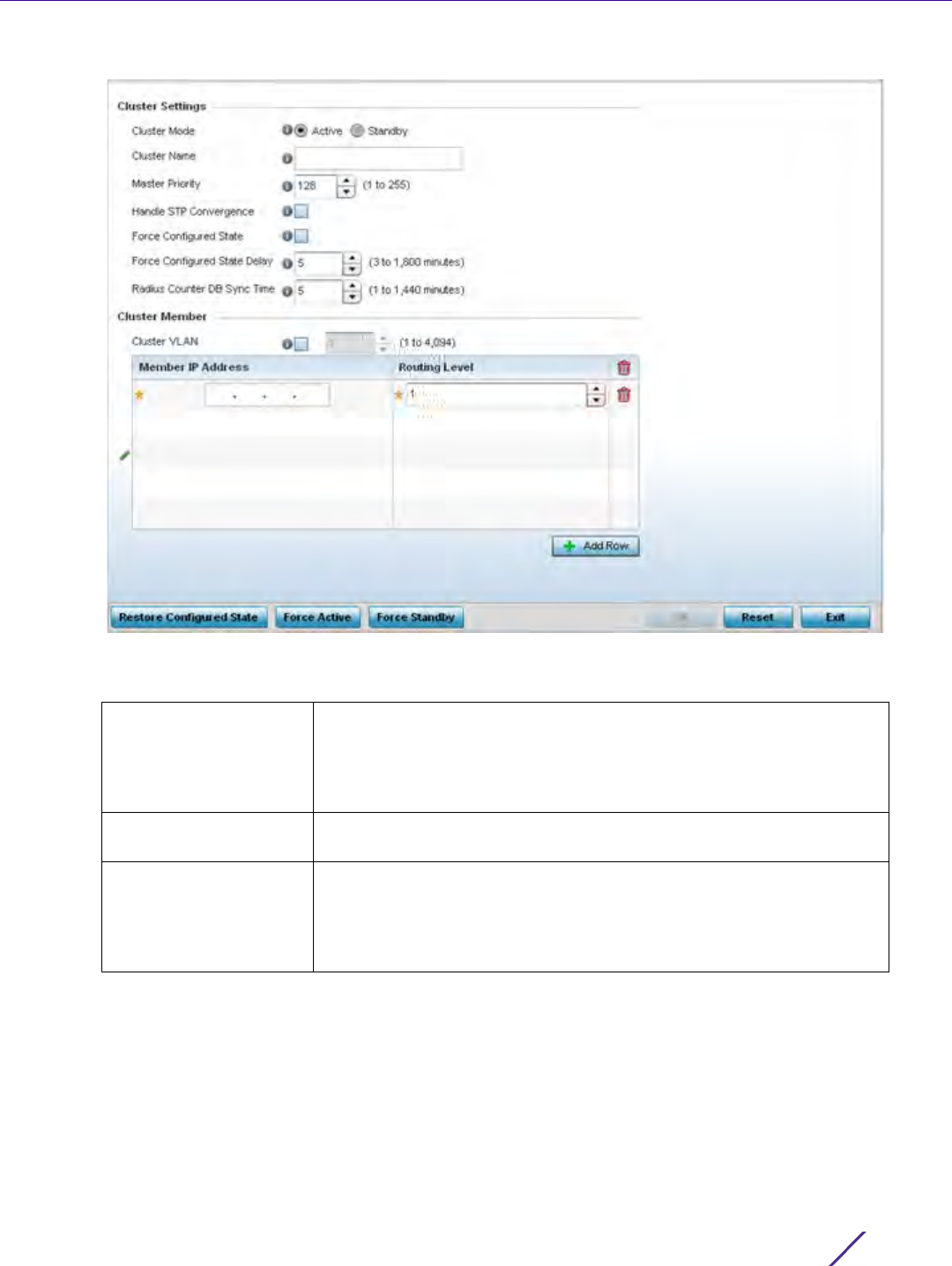
Device Configuration
Wireless Controller and Service Platform System Reference Guide 5 - 42
Figure 5-26 Profile Overrides - Cluster screen
6 Optionally define the following Cluster Settings and overrides:
Cluster Mode A member can be in either an Active or Standby mode. All active
member controllers or service platforms can adopt Access Points.
Standby members only adopt Access Points when an active member
has failed or sees an Access Point that’s not yet adopted. The default
cluster mode is Active and enabled for use with the profile.
Cluster Name Define a name for the cluster name unique to its configuration or
profile support requirements. The name cannot exceed 64 characters.
Master Priority Set a priority value from 1 and 255 with the higher value being given
higher priority. This configuration is the device’s priority to become
cluster master. In cluster environment one device from cluster
members is elected as cluster master. This configuration is the device’s
priority to become cluster master. The default is 128.

Device Configuration
Wireless Controller and Service Platform System Reference Guide 5 - 43
7Within the Cluster Member field, select Cluster VLAN to enable a spinner control to designate the VLAN where
cluster members are reachable. Specify a VLAN from 1 - 4094.
Specify the IP addresses of the VLAN’s cluster members using the Member IP Address table.
8Select
Restore Configured State to restore this cluster member back into role of taking over for an active
member if it were to fail.
9Select
Force Active to revert this cluster member back into its default active state and provide the ability to
adopt Access Points.
10 Select Force Standby to only adopt Access Points when an active member has failed or sees an Access Point
that’s not yet adopted.
11 Select OK to save the changes and overrides made to the profile’s cluster configuration. Select Reset to revert
to the last saved configuration.
Handle STP
Convergence
Select the radio button to enable Spanning Tree Protocol (STP)
convergence for the controller or service platform. In general, this
protocol is enabled in layer 2 networks to prevent network looping.
Spanning Tree is a network layer protocol that ensures a loop-free
topology in a mesh network of inter-connected layer 2 controller or
service platform. The spanning tree protocol disables redundant
connections and uses the least costly path to maintain a connection
between any two controllers or service platforms in the network. If
enabled, the network forwards data only after STP convergence.
Enabling STP convergence delays the redundancy state machine
execution until the STP convergence is completed (the standard
protocol value for STP convergence is 50 seconds). Delaying the state
machine is important to load balance APs at startup. The default
setting is disabled.
Force Configured State Select the radio button to allow this controller or service platform to
take over for an active member if it were to fail. A standby controller or
service platform in the cluster takes over APs adopted by the failed
active member. If the failed active member were to come back up, the
active member starts a timer based on the Auto Revert Delay interval.
At the expiration of the Auto Revert Delay, the standby member
releases all adopted APs and goes back to a monitoring mode. The
Auto Revert Delay timer is stopped and restarted if the active member
goes down and comes up during the Auto Revert Delay interval. The
default value is disabled.
Force Configured State
Delay
Specify a delay interval in minutes (3 - 1,800). This is the interval a
standby member waits before releasing adopted APs and goes back to
a monitoring mode when an active cluster member becomes active
again after a failure. The default interval is 5 minutes.
Radius Counter DB Sync
Time
Specify a sync time (from 1 - 1,440 minutes) a RADIUS counter
database uses as its synchronization interval with the dedicated NTP
server resource. The default interval is 5 minutes.
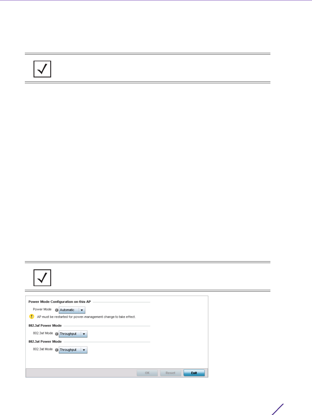
Device Configuration
Wireless Controller and Service Platform System Reference Guide 5 - 44
5.2.6.2 Access Point Radio Power Overrides (Access Points Only)
Profile Overrides
A profile can manage the transmit output power of the Access Point radios it supports within the network.
Use the Power screen to set or override one of two power modes (3af or Auto) for a managed Access Point. When
automatic is selected, the Access Point safely operates within available power. Once the power configuration is
determined, the Access Point configures its operating power characteristics based on its model and power
configuration.
An Access Point uses a complex programmable logic device (CPLD). The CPLD determines proper supply
sequencing, the maximum power available and other status information. One of the primary functions of the CPLD
is to determine the Access Point’s maximum power budget. When an Access Point is powered on (or performing a
cold reset), the CPLD determines the maximum power provided by the POE device and the budget available to
the Access Point. The CPLD also determines the access point hardware SKU and the number of radios. If the
Access Point’s POE resource cannot provide sufficient power (with all intended interfaces enabled), some of the
following interfaces could be disabled or modified:
• The Access Point’s transmit and receive algorithms could be negatively impacted
• The Access Point’s transmit power could be reduced due to insufficient power
• The Access Point’s WAN port configuration could be changed (either enabled or disabled)
To define an Access Point’s power configuration or apply an override to an existing parameter:
1 Select the Devices tab from the Web UI.
2Select
Profile Overrides to expand its sub menu items.
3Select
Power.
A screen displays where an Access Point’s power configuration can be defined or overridden for a profile.
Figure 5-27 Access Point Profile Power Override screen
NOTE: The Power option only appears within the Profile Overrides menu tree if an
Access Point is selected from within the main Devices screen. Power management
is configured differently for controllers or service platforms, so the Power screen
only displays for Access Points.
NOTE: A blue override icon (to the left of a parameter) defines the parameter as
having an override applied. To remove an override go to the Basic Configuration
section of the device and click the Clear Overrides button. This removes all
overrides from the device.
Device Configuration
Wireless Controller and Service Platform System Reference Guide 5 - 45
4 Use the Power Mode drop-down menu to set or override the Power Mode Configuration on this AP.
When an Access Point is powered on for the first time, the system determines the power budget available to
the Access Point. Using the Automatic setting, the Access Point automatically determines the best power
configuration based on the available power budget. Automatic is the default setting.
If 802.3af is selected, the Access Point assumes 12.95 watts are available. If the mode is changed, the Access
Point requires a reset to implement the change. If 802.3at is selected, the Access Point assumes 23 - 26 watts
are available.
5 Set or override the Access Point radio’s 802.3af Power Mode and the radio’s 802.3at Power Mode.
Use the drop-down menu to define a mode of either Range or Throughput.
Select Throughput to transmit packets at the radio’s highest defined basic rate (based on the radio’s current
basic rate settings). This option is optimal in environments where the transmission range is secondary to
broadcast/multicast transmission performance. Select Range when range is preferred over performance for
broadcast/multicast (group) traffic. The data rates used for range are the lowest defined basic rates.
Throughput is the default setting for both 802.3af and 802.3at.
6Select
OK to save the changes and overrides made to the Access Point power configuration. Select Reset to
revert to the last saved configuration.
5.2.6.3 Access Point Adoption Overrides (Access Points Only)
Profile Overrides
Adoption is the process an Access Point uses to discover available controllers or service platforms, pick the most
desirable one, establish an association and optionally obtain an image upgrade and configuration. Adoption is
configurable and supported within a device profile and applied to other Access Points supported by the profile.
Individual attributes of an Access Point’s auto provisioning policy can be overridden as specific parameters require
modification.
At adoption, an Access Point solicits and receives multiple adoption responses from controllers and service
platforms available on the network. These adoption responses contain loading policy information the Access Point
uses to select the optimum controller or service platform for adoption. By default, an auto provisioning policy
generally distributes AP adoption evenly amongst available controllers and service platforms. Modify existing
adoption policies or create a new one as needed to meet the adoption requirements of a device and their assigned
profile.
An auto provisioning policy enables an administrator to define adoption rules for the supported Access Points
capable of being adopted by a wireless controller.
To define an Access Point’s adoption configuration or apply an override:
1 Select the Devices from the Web UI.
2Select
Profiles from the Configuration tab.
NOTE: Single radio model Access Point’s always operate using a full power
configuration. The power management configurations described in this section do
not apply to single radio models.
NOTE: A device configuration does not need to be present for an auto provisioning
policy to take effect. Once adopted, and the device’s configuration is defined and
applied by the controller or service platform, the auto provisioning policy mapping
does not have impact on subsequent adoptions by the same device.
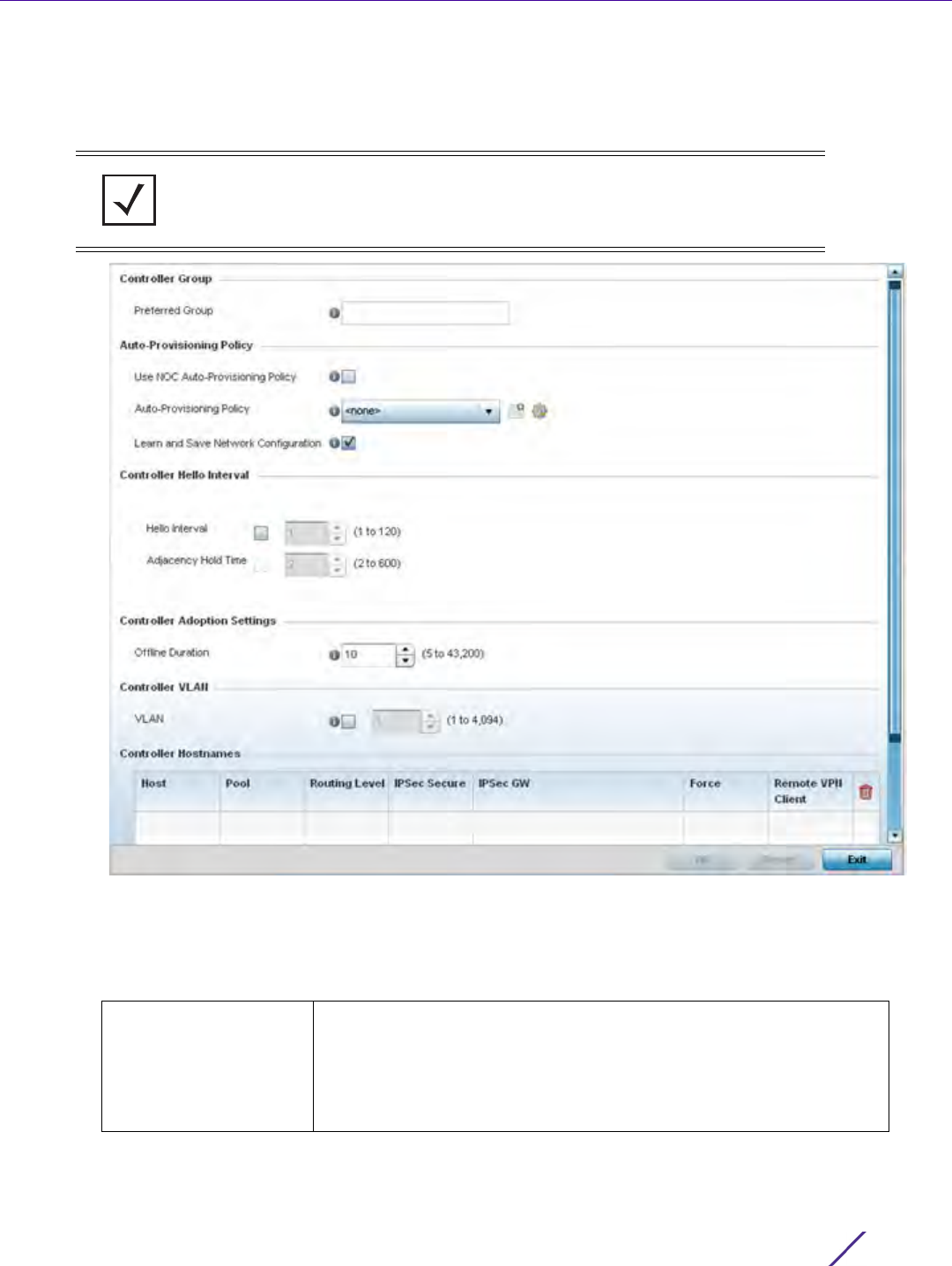
Device Configuration
Wireless Controller and Service Platform System Reference Guide 5 - 46
3Select
Profile Overrides to expand its sub-menu items.
4Select
Adoption.
A screen displays where an Access Point’s adoption configuration can be defined and overridden for a profile.
Figure 5-28 Access Point Adoption Override screen
5 Define or override the Preferred Group used as optimal group for the Access Point’s adoption. The name of the
preferred group cannot exceed 64 characters.
6 Set the following Auto-Provisioning Policy settings for Access Point adoptions:
NOTE: A blue override icon (to the left of a parameter) defines the parameter as
having an override applied. To remove an override go to the Basic Configuration
section of the device and click the Clear Overrides button. This removes all
overrides from the device.
Use NOC
Auto-Provisioning
Policy
Select this option to use the NOC controller’s auto provisioning policy
and not the policy maintained locally. The NOC is an elected controller
or service platform capable of provisioning all of its peer controllers,
service platforms and adopted devices. This setting is disabled by
default. NOC controllers are NX9000, NX9500, NX9510, NX7500, and
RFS6000 models.

Device Configuration
Wireless Controller and Service Platform System Reference Guide 5 - 47
7 Set the following Controller Hello Interval settings manage message exchanges and connection re-
establishments between adopting devices:
8 Use the spinner control to define an Offline Duration timeout (from 5 - 43,200 minutes) to detect whether an
adopted device is offline. The default setting is 10 minutes.
9 Use the spinner control to define a Controller VLAN. Select to enable this field and select the VLAN on which
the adopting controllers can be found by the Access Point.
10 Enter Controller Hostnames as needed to define or override resources for Access Point adoption.
11 Select + Add Row as needed to populate the table with IP Addresses or Hostnames used as Access Point
adoption resources into the managed network.
12 Select OK to save the changes and overrides made to the Access Point profile adoption configuration. Select
Reset to revert to the last saved configuration.
Auto-Provisioning
Policy
Select an auto provisioning policy from the drop-down menu. To create
a new auto provisioning policy, select the Create icon or modify an
existing one by selecting the Edit icon.
Learn and Save Network
Configuration
Select this option to learn and save the configuration of any device
requesting adoption. This setting is enabled by default.
Hello Interval Define an interval (from 1 - 120 seconds) between hello keep alive
messages exchanged with the adopting device. These messages serve
as a connection validation mechanism to ensure the availability of the
adopting resource.
Adjacency Hold Time Set the time (from 2 - 600 seconds) after the last hello packet after
which the connection between the controller and Access Point is
defined as lost and their connection is re-established. When a hello
interval is set, an adjacency hold time is mandatory and should be
higher then the hello interval.
Host Use the drop-down menu to specify whether the adoption resource is
defined as a (non DNS) IP Address or a Hostname. Once defined,
provide the numerical IP or Hostname. A Hostname cannot exceed 64
characters and cannot include an underscore character.
Pool Use the spinner control to set a pool of either 1 or 2. This is the pool
the target controller or service platform belongs to.
Routing Level Define a routing level (either 1 or 2) for the link between adopting
devices. The default setting is 1.
IPSec Secure Enable this option to provide IPSec secure peer authentication on the
connection (link) between the adopting devices. This option is disabled
by default.
IPSec GW Select the numerical IP address or administrator defined hostname of
the adopting controller resource.
Force Enable this setting to create a forced link between an Access Point and
adopting controller, even when not necessarily needed. This setting is
disabled by default.
Remote VPN Client Displays whether a secure controller link has been established using a
remote VPN client.
Device Configuration
Wireless Controller and Service Platform System Reference Guide 5 - 48
5.2.6.4 Adoption Overrides (Controllers Only)
Profile Overrides
Adoption is the process an Access Point uses to discover available controllers, pick the most desirable controller,
establish a controller association and optionally obtain an image upgrade and configuration. Adoption is
configurable and supported within a device profile and applied to other Access Points supported by the profile.
Individual attributes of an Access Point’s auto provisioning policy can be overridden as specific parameters require
modification.
At adoption, an Access Point solicits and receives multiple adoption responses from controllers and service
platforms available on the network. These adoption responses contain loading policy information the Access Point
uses to select the optimum controller or service platform for adoption. By default, an auto provisioning policy
generally distributes AP adoption evenly amongst available controllers and service platforms. Modify existing
adoption policies or create a new one as needed to meet the adoption requirements of a device and their assigned
profile.
To define a controller or service platform’s adoption configuration:
1 Select the Devices from the Web UI.
2Select
Profiles.
3Select Profile Overrides to expand its sub-menu items.
4Select
Adoption.
A screen displays where a controller or service platform’s adoption configuration can be set or overridden for a
profile.
NOTE: A device configuration does not need to be present for an auto provisioning
policy to take effect. Once adopted, and the device’s configuration is defined and
applied by the controller or service platform, the auto provisioning policy mapping
does not have impact on subsequent adoptions by the same device.
NOTE: A blue override icon (to the left of a parameter) defines the parameter as
having an override applied. To remove an override go to the Basic Configuration
section of the device and click the Clear Overrides button. This removes all
overrides from the device.
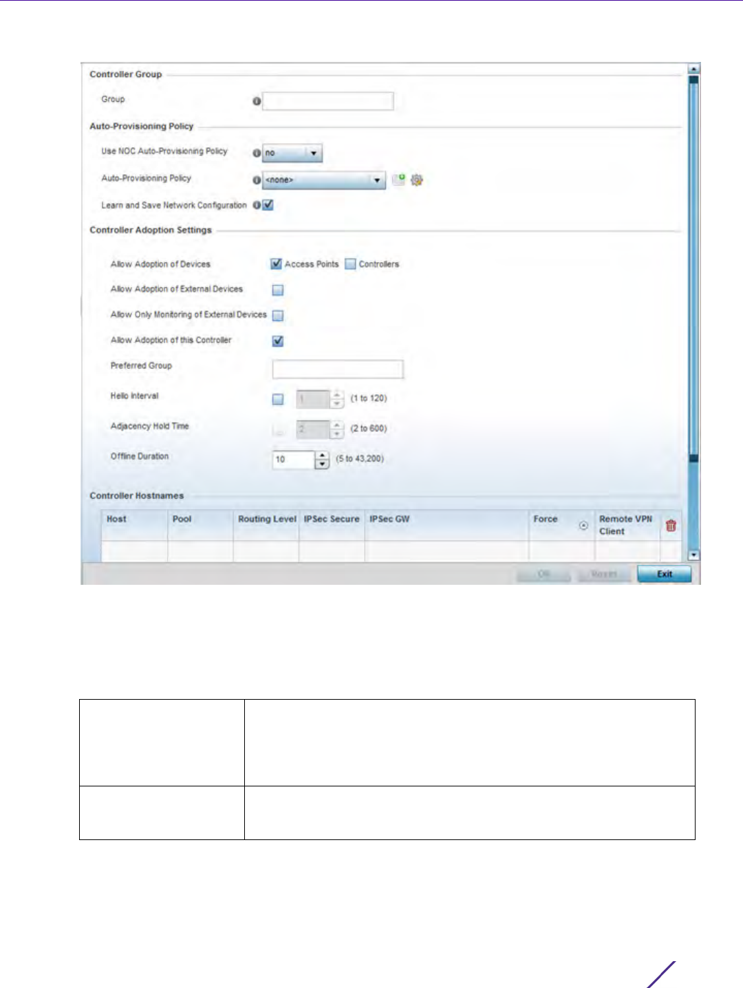
Device Configuration
Wireless Controller and Service Platform System Reference Guide 5 - 49
Figure 5-29 Controller Adoption Override screen
5Within the Controller Group field, use the Group item to set provide the controller group this controller or
service platform belongs to. A preferred group can also be selected for the adoption of this controller or service
platform. The name of the preferred group cannot exceed 64 characters.
6 Set the following Auto Provisioning Policy parameters:
Use NOC
Auto-Provisioning
Policy
Select this option to use the NOC’s auto provisioning policy instead of
the policy local to the controller or service platform. The NOC is an
elected controller or service platform capable of provisioning all of its
peer controllers, service platforms and adopted devices. This setting is
disabled by default.
Auto-Provisioning
Policy
Select an auto provisioning policy from the drop-down menu. To create
a new auto provisioning policy, select the Create icon or modify an
existing one by selecting the Edit icon.

Device Configuration
Wireless Controller and Service Platform System Reference Guide 5 - 50
7 Set the following Controller Adoption Settings settings:
8Enter
Controller Hostnames as needed to define resources for adoption.
9Select
+ Add Row as needed to populate the table with IP Addresses or Hostnames used as Access Point
adoption resources into the managed network.
Learn and Save Network
Configuration
Select this option to enable allow the controller tor service platform to
maintain a local configuration records of devices requesting adoption
and provisioning. This feature is enabled by default.
Rerun Policy Rules
Every Time AP Adopted
Enabling this feature applies adoption rules on Access Points each time
they’re subsequently adopted, not just the first time. This setting is
disabled by default.
Allow Adoption of
Devices
Select either Access Points or Controllers (or both) to refine whether
this controller or service platform can adopt just networked Access
Points or peer controller devices as well.
Allow Adoption of
External Devices
Select this option to enable this controller or service platform to adopt
T5 model devices or EX3500 model switches.
Allow Monitoring of
External Devices
Select this option to enable monitoring only of T5 model devices or
EX3500 model switches by this controller or service platform. When
enabled, WiNG does not configure EX3500 switches or a T5, it only
monitors those devices for statistics and events.
Allow Adoption of this
Controller
Select this option to enable this controller or service platform to be
capable of adoption by other controllers or service platforms. This
setting is disabled by default, and must be selected to allow peer
adoptions and enable the four settings directly below it.
Preferred Group If Allow Adoption of this Controller is selected, provide the controller
group preferred as the adopting entity for this controller or service
platform. If utilizing this feature, ensure the appropriate group is
provided within the Controller Group field.
Hello Interval Select this option to define the hello packet exchange interval (from 1 -
120 seconds) between the controller or service platform and an
adoption requesting Access Point.
Adjacency Hold Time Select this option to set a hold time interval (from 2 - 600 seconds)
for the transmission of hello packets.
Offline Duration Use the spinner control to define a timeout (from 5 - 43,200 minutes)
to detect whether an adopted device is offline. The default setting is
10 minutes.
Host Use the drop-down menu to specify whether the adoption resource is
defined as a (non DNS) IP Address or a Hostname. Once defined,
provide the numerical IP or Hostname. A Hostname cannot exceed 64
characters or contain an underscore.
Pool Use the spinner control to set a pool of either 1 or 2. This is the pool
the target controller or service platform belongs to.
Routing Level Define a routing level (either 1 or 2) for the link between adopting
devices. The default setting is 1.
IPSec Secure Enable this option to provide IPSec secure peer authentication on the
connection (link) between the adopting devices. This option is disabled
by default.

Device Configuration
Wireless Controller and Service Platform System Reference Guide 5 - 51
10 Select OK to save the changes and overrides made to the profile’s adoption configuration. Select Reset to revert
to the last saved configuration.
5.2.7 Profile Interface Override Configuration
Profile Overrides
A profile’s interface configuration can be defined to support separate physical Ethernet configurations both unique
and specific to RFS4000, RFS6000 controllers and NX5500, NX7500 and NX9000 series service platforms. Ports
vary depending on platform, but controller or service platform models do have some of the same physical
interfaces.
A controller or service platform requires its Virtual Interface be configured for layer 3 (IP) access or layer 3 service
on a VLAN. A Virtual Interface defines which IP address is associated with each VLAN ID the controller or service
platform is connected to.
If the profile is configured to support an Access Point radio, an additional Radios option is available, unique to the
Access Point’s radio configuration.
Each profile interface configuration can have overrides applied to customize the configuration to a unique
controller or service platform deployment. However, once an override is applied to this configuration it becomes
independent from the profile that may be shared by a group of devices in a specific deployment and my need
careful administration until a profile can be re-applied to the target controller or service platform. For more
information, refer to the following:
•Ethernet Port Override Configuration
•Virtual Interface Override Configuration
•Port Channel Override Configuration
•VM Interface Override Configuration
•Radio Override Configuration
•WAN Backhaul Override Configuration
•PPPoE Override Configuration
•Bluetooth Configuration
5.2.7.1 Ethernet Port Override Configuration
Profile Interface Override Configuration
The ports available on controllers vary depending RFS controller model. The following ports are available to
controllers:
•RFS4000 - ge1, ge2, ge3, ge4, ge5, up1
• RFS6000 - ge1, ge2, ge3, ge4, ge5, ge6, ge7, ge8, me1, up1
GE ports on RFS4000 and RFS6000 models are RJ-45 ports supporting 10/100/1000Mbps.
IPSec GW Select the numerical IP address or administrator defined hostname of
the adopting controller resource.
Force Enable this setting to create a forced link between an Access Point and
adopting controller, even when not necessarily needed. This setting is
disabled by default.
Remote VPN Client Displays whether a secure controller link has been established using a
remote VPN client.

Device Configuration
Wireless Controller and Service Platform System Reference Guide 5 - 52
ME ports are available on RFS6000 and RFS7000 platforms. ME ports are out-of-band management ports used to
manage the controller via CLI or Web UI, even when the other ports on the controller are unreachable.
The following ports are available to NX series service platform models:
•NX5500 - ge1, ge2
•NX7500 - ge1-ge10, xge1-xge2
•NX9000 series - ge1, ge2
UP ports are available on RFS4000 and RFS6000 controller. An UP port supports either RJ-45 or fiber. The UP port is the
preferred means to connect to the backbone as it has a non-blocking 1gbps connection unlike the GE ports.
The following ports are available on Access Points:
• AP6521 - GE1/POE (LAN)
• AP6522 - GE1/POE (LAN)
• AP6532 - GE1/POE
• AP6562 - GE1/POE
• AP7161 - GE1/POE (LAN), GE2 (WAN)
• AP7502 - GE1 (THRU), fe1, fe2, fe3,
• AP7522 - GE1/POE (LAN)
•AP7532 - GE1/POE (LAN)
• AP7602 - GE1/POE (LAN), GE2 (WAN)
• AP7612 - GE1/POE (LAN), GE2 (WAN)
• AP7622 - GE1/POE (LAN)
• AP7632 - GE1/POE (LAN)
• AP7662 - GE1/POE (LAN), GE2 (WAN)
• AP81XX - GE1/POE (LAN), GE2 (WAN)
• AP82XX - GE1/POE (LAN), GE2 (WAN)
T5 controllers have the following Ethernet port designations:
•T5- ge1-ge2 (T5 controller managed CPE devices have ports fe1 - fe2)
To set a profile’s Ethernet port configuration and potentially apply overrides to the profile’s configuration:
1 Select the Configuration tab from the Web UI.
2Select
Devices from the Configuration tab.
The Device Configuration screen displays a list of managed devices or peer controllers, service platforms or
Access Points.
3 Select a target device (by double-clicking it) from amongst those displayed within the Device Configuration
screen.
Devices can also be selected directly from the Device Browser in the lower, left-hand, side of the UI.
4Select
Profile Overrides from the Device menu to expand it into sub menu options.
5Select
Interface to expand its sub menu options.
NOTE: For a NX7500 model service platform, there are options for either a 2 port
or 4 port network management card. Either card can be managed using WiNG. If
the 4 port card is used, ports ge7-ge10 are available. If the 2 port card is used, ports
xge1-xge2 are available.
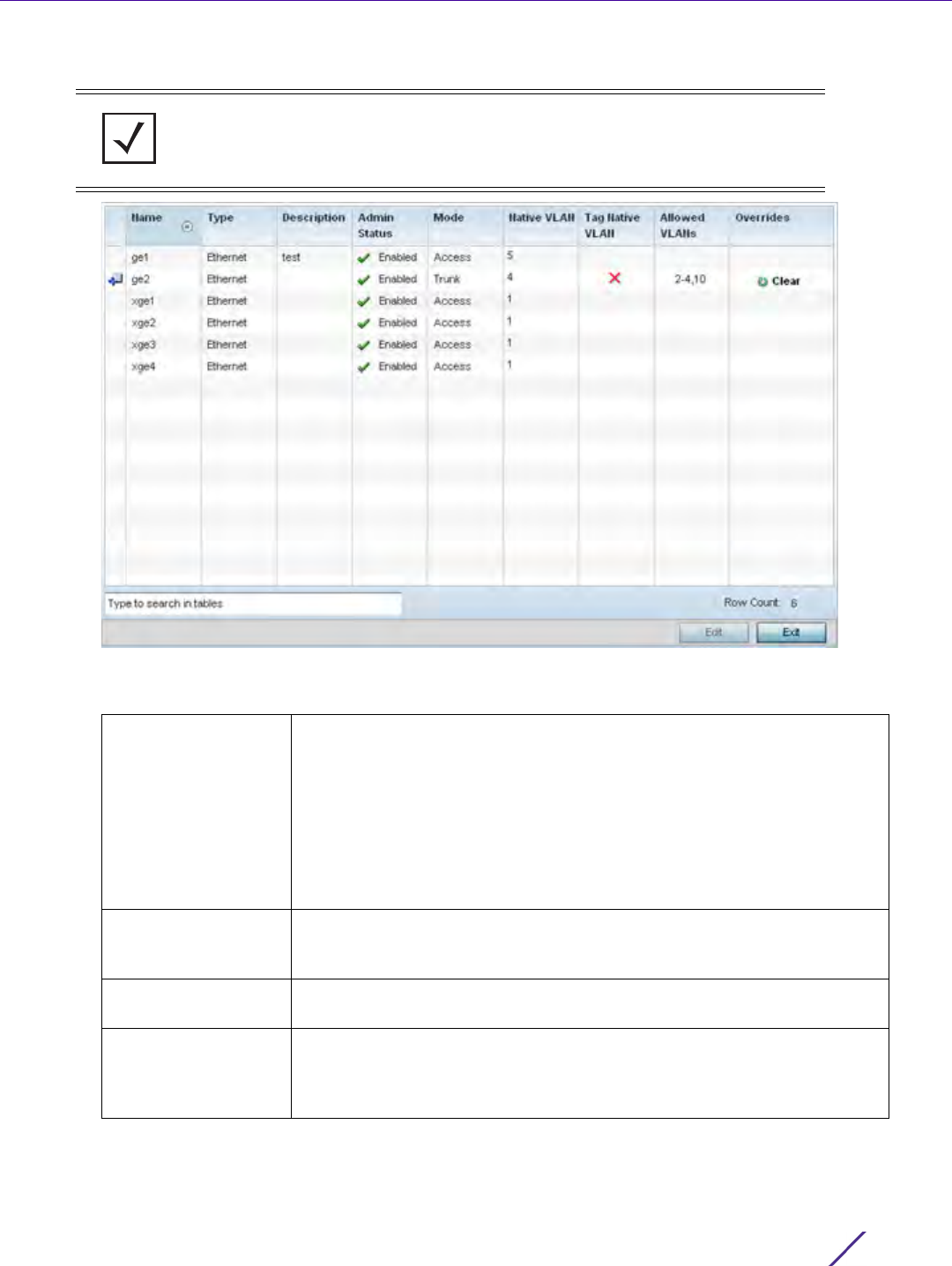
Device Configuration
Wireless Controller and Service Platform System Reference Guide 5 - 53
6Select
Ethernet Ports.
Figure 5-30 Profiles Overrides - Ethernet Ports screen
7 Refer to the following to assess port status and performance:
NOTE: A blue override icon (to the left of a parameter) defines the parameter as
having an override applied. To remove an override go to the Basic Configuration
section of the device and click the Clear Overrides button. This removes all
overrides from the device.
Name Displays the physical port name reporting runtime data and statistics.
Supported ports vary depending on controller or service platform model.
RFS4000 - ge1, ge2, ge3, ge4, ge5, up1
RFS6000 - ge1, ge2, ge3, ge4, ge5, ge6, ge7, ge8, me1, up1
NX5500 - ge1, ge2
NX7500 - ge1-ge10, xge1-xge2
NX9000 series- ge1, ge2, xge1-xge4
Type Displays the physical controller or service platform port type. Cooper is
used on RJ45 Ethernet ports and Optical materials are used on fiber optic
gigabit Ethernet ports.
Description Displays an administrator defined description for each listed controller or
service platform port.
Admin Status A green check mark defines the port as active and currently enabled with
the profile. A red “X” defines the port as currently shut down and not
available for use. The interface status can be modified with the port
configuration as needed.

Device Configuration
Wireless Controller and Service Platform System Reference Guide 5 - 54
8 To edit or override the configuration of an existing controller or service platform port, select it from amongst
those displayed and select the Edit button. The Ethernet Port Basic Configuration screen displays by default.
Mode Displays the profile’s switching mode as either Access or Trunk (as
defined within the Ethernet Port Basic Configuration screen). If Access is
selected, the listed port accepts packets only from the native VLAN.
Frames are forwarded untagged with no 802.1Q header. All frames
received on the port are expected as untagged and mapped to the native
VLAN. If set to Trunk, the port allows packets from a list of VLANs added
to the trunk. A port configured as Trunk supports multiple 802.1Q tagged
VLANs and one Native VLAN which can be tagged or untagged.
Native VLAN Lists the numerical VLAN ID (1 - 4094) set for the native VLAN. The
native VLAN allows an Ethernet device to associate untagged frames to a
VLAN when no 802.1Q frame is included in the frame. Additionally, the
native VLAN is the VLAN untagged traffic is directed over when using a
port in trunk mode.
Tag Native VLAN A green check mark defines the native VLAN as tagged. A red “X” defines
the native VLAN as untagged. When a frame is tagged, the 12 bit frame
VLAN ID is added to the 802.1Q header so upstream Ethernet devices
know which VLAN ID the frame belongs to. The device reads the 12 bit
VLAN ID and forwards the frame to the appropriate VLAN. When a frame
is received with no 802.1Q header, the upstream device classifies the
frame using the default or native VLAN assigned to the Trunk port. A
native VLAN allows an Ethernet device to associate untagged frames to a
VLAN when no 802.1Q frame is included in the frame.
Allowed VLANs Displays those VLANs allowed to send packets over the listed controller
or service platform port. Allowed VLANs are only listed when the mode
has been set to Trunk.
Overrides A Clear option appears for each Ethernet port configuration that has an
override applied to the profile’s configuration. Select Clear to revert this
specific interface configuration to the profile configuration originally
defined by the administrator for this interface.
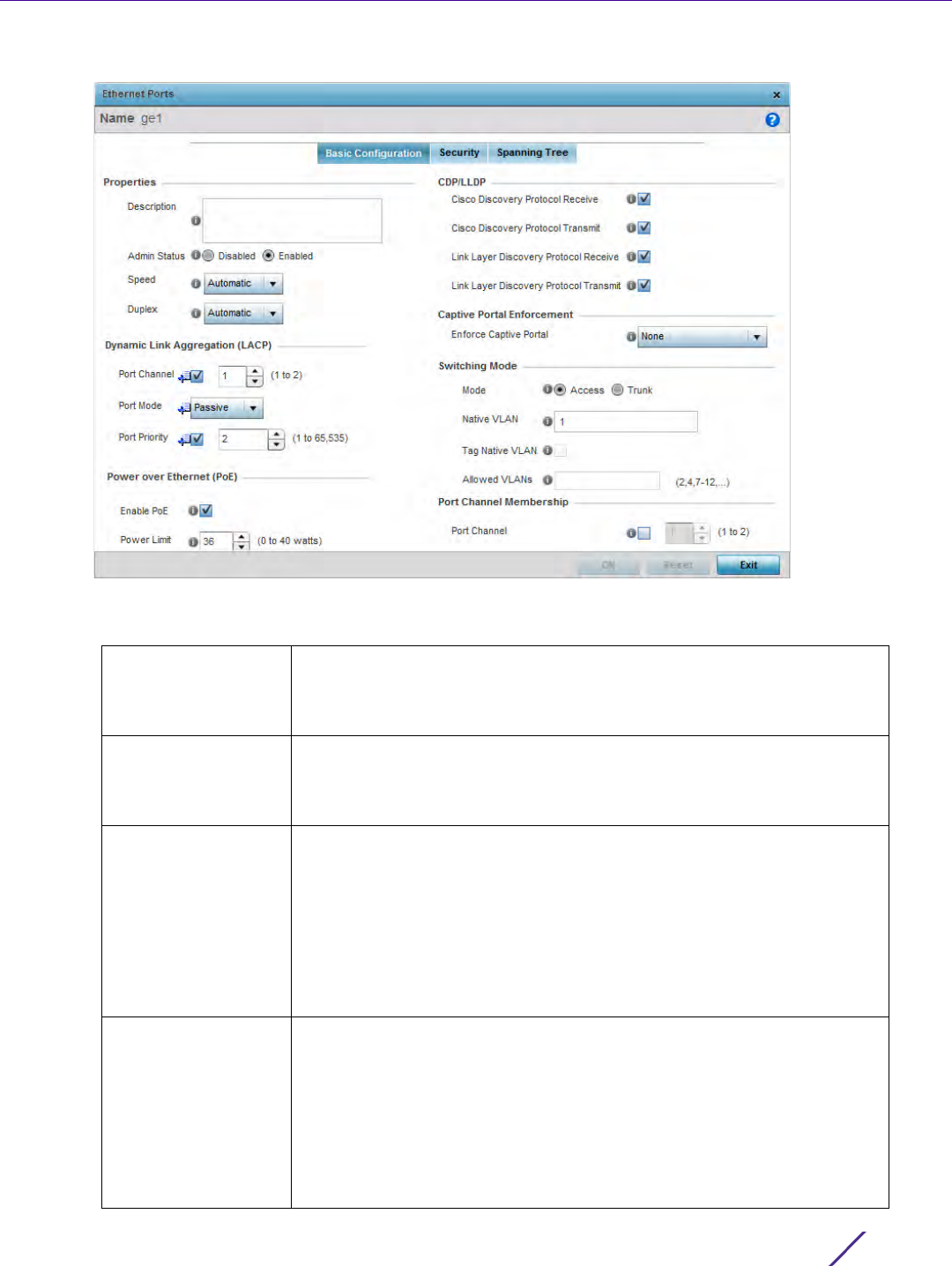
Device Configuration
Wireless Controller and Service Platform System Reference Guide 5 - 55
Figure 5-31 Profile Overrides - Ethernet Ports Basic Configuration screen
9 Set or override the following Ethernet port Properties:
Description Enter a brief description for the controller or service platform port (64
characters maximum). The description should reflect the port’s intended
function to differentiate it from others with similar configurations, or
perhaps just the name of the physical port.
Admin Status Select the Enabled radio button to define this port as active to the profile
it supports. Select the Disabled radio button to disable this physical port
in the profile. It can be activated at any future time when needed. Admin
status is enabled by default.
Speed Select the speed at which the port can receive and transmit the data.
Select either 10 Mbps, 100 Mbps or 1000 Mbps. Select either of these
options to establish a 10, 100 or 1000 Mbps data transfer rate for the
selected half duplex or full duplex transmission over the port. These
options are not available if Auto is selected. Select Automatic to enable
the port to automatically exchange information about data transmission
speed and duplex capabilities. Auto negotiation is helpful when in an
environment where different devices are connected and disconnected on
a regular basis. Automatic is the default setting.
Duplex Select either Half, Full or Automatic as the duplex option. Select Half
duplex to send data over the port, then immediately receive data from the
same direction in which the data was transmitted. Like a Full-duplex
transmission, a Half-duplex transmission can carry data in both directions,
just not at the same time. Select Full duplex to transmit data to and from
the port at the same time. Using Full duplex, the port can send data while
receiving data as well. Select Automatic to enable to the controller or
service platform to dynamically duplex as port performance needs
dictate. Automatic is the default setting.

Device Configuration
Wireless Controller and Service Platform System Reference Guide 5 - 56
10 Enable or disable the following CDP/LLDP parameters used to configure Cisco Discovery Protocol (CDP) and
Link Layer Discovery Protocol (LLDP) for this profile’s Ethernet port configuration:
11 If supported and applicable, set or override the following Power Over Ethernet (PoE) parameters used with this
profile’s Ethernet port configuration:
12 Select Enforce Captive Portal to automatically apply captive portal access permission rules to data transmitted
over this specific Ethernet port. This setting is disabled by default.
A captive portal is an access policy for providing temporary and restrictive access using a standard Web
browser. Captive portals provides authenticated access by capturing and re-directing a wireless user's Web
browser session to a captive portal login page where the user must enter valid credentials to access to the
network. Once logged into the captive portal, additional Terms and Agreement, Welcome, Fail and No Service
pages provide the administrator with a number of options on captive portal screen flow and user appearance.
Captive portal enforcement allows wired network users to pass traffic through the captive portal without being
redirected to an authentication page. Authentication instead takes place when the RADIUS server is queried
against the wired user's MAC address. If the MAC address is in the RADIUS server's user database, the user can
pass traffic on the captive portal. If None is selected, captive portal policies are not enforced on the wired
interface. If Authentication Failure is selected, captive portal policies are enforced only when RADIUS
authentication of the client’s MAC address is not successful. If Always is selected, captive portal policies are
enforced regardless of whether the client's MAC address is in the RADIUS server's user database. For
information on configuring a captive portal policy, see Configuring Captive Portal Policies on page 11-1.
Cisco Discovery
Protocol Receive
Select this option to allow the CDP to be received on this port. If enabled,
the port sends out periodic interface updates to a multicast address to
advertise its presence to neighbors. This option is enabled by default.
Cisco Discovery
Protocol Transmit
Select this option to allow the CDP to be transmitted on this port. If
enabled, the port sends out periodic interface updates to a multicast
address to advertise its presence to neighbors.
Link Layer Discovery
Protocol Receive
Select this option to allow the LLDP to be received on this port. If
enabled, the port sends out periodic interface updates to a multicast
address to advertise its presence to neighbors. This option is enabled by
default.
Link Layer Discovery
Protocol Transmit
Select this option to allow the LLDP to be transmitted on this port. If
enabled, the port sends out periodic interface updates to a multicast
address to advertise its presence to neighbors.
Enable POE Select this option to configure the selected controller or service platform
port to use Power over Ethernet. To disable PoE on a port, uncheck this
option. PoE is supported on RFS4000 and RFS6000 model controllers.
When enabled, the controller or service platform supports 802.3af PoE on
each of its ge ports. The PoE allows users to monitor port power
consumption and configure power usage limits and priorities for each ge
port.
Power Limit Use the spinner control to set the total watts available for PoE on the ge
port. Set a value from 0 - 40 watts.
Power Priority Set the power priority for the listed port to either to either Critical, High
or Low. This is the priority assigned to this port versus the power
requirements of the other supports available on the controller or service
platform.

Device Configuration
Wireless Controller and Service Platform System Reference Guide 5 - 57
13 Define or override the following Switching Mode parameters applied to the Ethernet port configuration:
14 Optionally select the Port Channel check box from the Port Channel Membership area and define or override a
setting from 1 - 8 using the spinner control. This sets the channel group for the port.
15 Select OK to save the changes and overrides made to the profile’s Ethernet Port Basic Configuration. Select
Reset to revert to the last saved configuration.
16 Select the Security tab.
Mode Select either the Access or Trunk radio button to set the VLAN switching
mode over the port. If Access is selected, the port accepts packets only
form the native VLANs. Frames are forwarded out the port untagged with
no 802.1Q header. All frames received on the port are untagged and are
mapped to the native VLAN. If the mode is set to Trunk, the port allows
packets from a list of VLANs you add to the trunk. A port configured as
Trunk supports multiple 802.1Q tagged VLANs and one Native VLAN
which can be tagged or untagged. Access is the default mode.
Native VLAN Use the spinner control to define a numerical Native VLAN ID from 1 -
4094. The native VLAN allows an Ethernet device to associate untagged
frames to a VLAN when no 802.1Q frame is included in the frame.
Additionally, the native VLAN is the VLAN which untagged traffic will be
directed over when using a port in trunk mode. The default VLAN is 1.
Tag Native VLAN Select this option to tag the native VLAN. Controller and service
platforms support the IEEE 802.1Q specification for tagging frames and
coordinating VLANs between devices. IEEE 802.1Q adds four bytes to
each frame identifying the VLAN ID for upstream devices that the frame
belongs. If the upstream Ethernet device does not support IEEE 802.1Q
tagging, it does not interpret the tagged frames. When VLAN tagging is
required between devices, both devices must support tagging and be
configured to accept tagged VLANs. When a frame is tagged, the 12 bit
frame VLAN ID is added to the 802.1Q header so upstream Ethernet
devices know which VLAN ID the frame belongs to. The device reads the
12 bit VLAN ID and forwards the frame to the appropriate VLAN. When a
frame is received with no 802.1Q header, the upstream device classifies
the frame using the default or native VLAN assigned to the Trunk port.
The native VLAN allows an Ethernet device to associate untagged frames
to a VLAN when no 802.1Q frame is included in the frame. This feature is
disabled by default.
Allowed VLANs Selecting Trunk as the mode enables the Allowed VLANs parameter. Add
VLANs that exclusively send packets over the listed port.
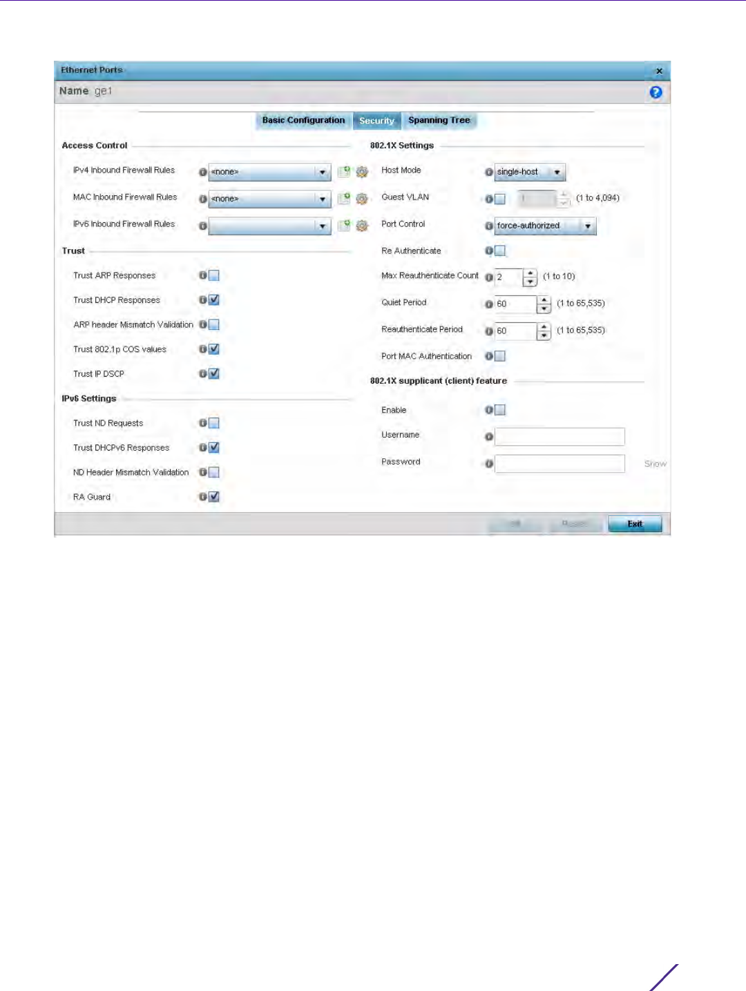
Device Configuration
Wireless Controller and Service Platform System Reference Guide 5 - 58
Figure 5-32 Profile Overrides - Ethernet Ports Security screen
17 Refer to the Access Control field. As part of the Ethernet port’s security configuration, Inbound IP and MAC
address firewall rules are required.
18 Use the MAC Inbound Firewall Rules drop-down menus to select the firewall rules to apply to this profile’s
Ethernet port configuration. The firewall inspects MAC traffic flows and detects attacks typically not visible to
traditional wired firewall appliances.
Use the IPv4 Inbound Firewall Rules drop down menu to select the IPv4 specific firewall rules to apply to this
profile’s Ethernet port configuration. IPv4 is a connectionless protocol for packet switched networking. IPv4
operates as a best effort delivery method, as it does not guarantee delivery, and does not ensure proper
sequencing or duplicate delivery (unlike (TCP). IPv4 hosts can use link local addressing to provide local
connectivity.
19 Use the IPv6 Inbound Firewall Rules drop down menu to select the IPv6 specific firewall rules to apply to this
profile’s Ethernet port configuration. IPv6 is the latest revision of the Internet Protocol (IP) designed to replace
IPv4. IPV6 provides enhanced identification and location information for computers on networks routing traffic
across the Internet. IPv6 addresses are composed of eight groups of four hexadecimal digits separated by
colons.
20 If a firewall rule does not exist suiting the data protection needs of the target port configuration, select the
Create icon to define a new rule configuration or the Edit icon to update or override an existing configuration.
For more information, see Configuring IP Firewall Rules on page 10-20 or Wireless Firewall on page 10-1.
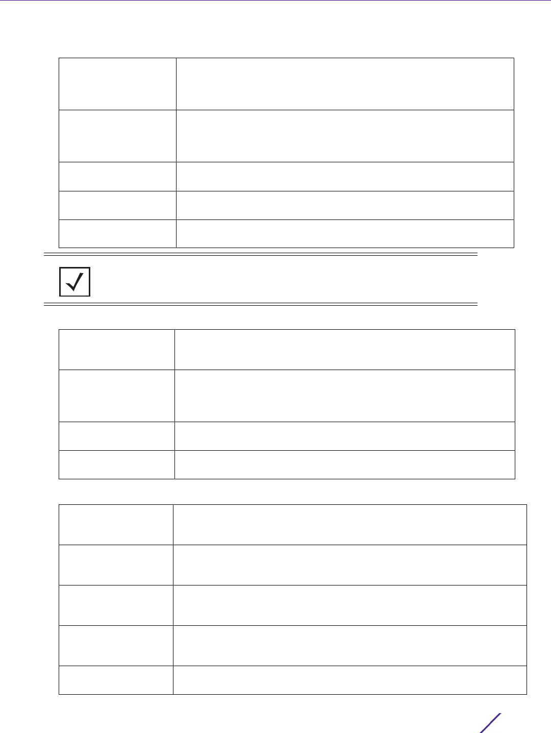
Device Configuration
Wireless Controller and Service Platform System Reference Guide 5 - 59
21 Refer to the Trust field to define or override the following:
22 Set the following IPv6 Settings:
23 Set the following 802.1X Settings:
Trust ARP Responses Select this option to enable ARP trust on this port. ARP packets
received on this port are considered trusted, and the information from
these packets is used to identify rogue devices within the network. The
default value is disabled.
Trust DHCP Responses Select this option to enable DHCP trust on this port. If enabled, only
DHCP responses are trusted and forwarded on this port, and a DHCP
server can be connected only to a DHCP trusted port. The default value
is enabled.
ARP header Mismatch
Validation
Select this option to enable a mismatch check for the source MAC in
both the ARP and Ethernet header. The default value is enabled.
Trust 802.1p COS
values
Select this option to enable 802.1p COS values on this port. The default
value is enabled.
Trust IP DSCP Select this option to enable IP DSCP values on this port. The default
value is enabled.
NOTE: Some vendor solutions with VRRP enabled send ARP packets with Ethernet
SMAC as a physical MAC and inner ARP SMAC as VRRP MAC. If this configuration is
enabled, a packet is allowed, despite a conflict existing.
Trust ND Requests Select this option to enable the trust of neighbor discovery requests
required on an IPv6 network on this Ethernet port. This setting is
disabled by default.
Trust DHCPv6
Responses
Select this option to enable the trust all DHCPv6 responses on this
Ethernet port. DHCPv6 is a networking protocol for configuring IPv6
hosts with IP addresses, IP prefixes or other configuration attributes
required on an IPv6 network. This setting is enabled by default.
ND Header Mismatch
Validation
Select this option to enable a mismatch check for the source MAC within
the ND header and Link Layer Option. This setting is disabled by default.
RA Guard Select this option to enable router advertisements or ICMPv6 redirects
from this Ethernet port. This setting is disabled by default.
Host Mode Use the drop-down menu to select the host mode configuration to apply to
this port. Options include single-host or multi-host. The default setting is
single-host.
Guest VLAN Specify a guest VLAN for this port from 1 - 4094. This is the VLAN traffic is
bridged on if this port is unauthorized and the guest VLAN is globally
enabled.
Port Control Use the drop-down menu to set the port control state to apply to this port.
Options include force-authorized, force-unauthorized and automatic. The
default setting is port-authorized.
Re Authenticate Select this setting to force clients to reauthenticate on this port. The default
setting is disabled, thus clients do not need to reauthenticate for
connection over this port until this setting is enabled.
Max Reauthenticate
Count
Set the maximum reauthentication attempts (1 - 10) before this port is
moved to unauthorized. The default setting is 2.
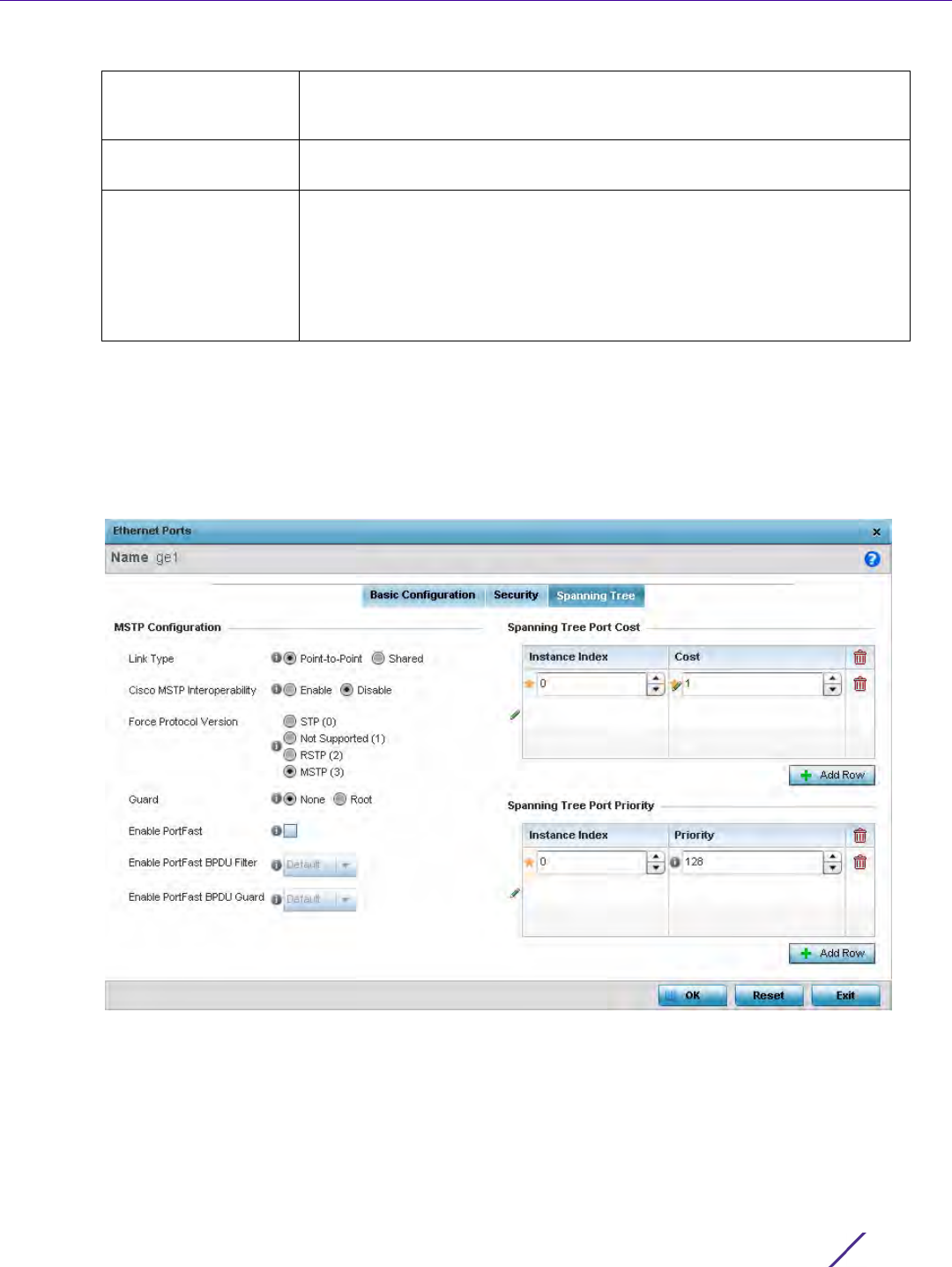
Device Configuration
Wireless Controller and Service Platform System Reference Guide 5 - 60
24 Select Enable within the 802.1x supplicant (client) feature field to enable a username and password pair used
when authenticating users on this port. This setting is disabled by default. The password cannot exceed 32
characters.
25 Select OK to save the changes and overrides made to the Ethernet port’s security configuration. Select Reset to
revert to the last saved configuration.
26 Select the Spanning Tree tab.
Figure 5-33 Profile Overrides - Ethernet Ports Spanning Tree screen
Quiet Period Set the quiet period for this port from 1 - 65,535 seconds.This is the
maximum wait time 802.1x waits upon a failed authentication attempt. The
default setting is 60 seconds.
Reauthenticate Period Use the spinner control to set the reauthentication period for this port from
1 - 65,535 seconds. The default setting is 60 seconds.
Port MAC
Authentication
When enabled, a port’s MAC address is authenticated, as only one MAC
address is supported per wired port. When successfully authenticated,
packets from the source are processed. Packets from all other sources are
dropped. Port MAC authentication is supported on RFS4000, RFS6000
model controllers and NX9000 series service platforms. Port MAC
authentication may be enabled on ports in conjunction with Wired 802.1x
settings for a MAC Authentication AAA policy.

Device Configuration
Wireless Controller and Service Platform System Reference Guide 5 - 61
27 Set or override the following parameters for the port’s MSTP Configuration:
28 Refer to the Spanning Tree Port Cost table.
Define or override an Instance Index using the spinner control and set the Cost. The default path cost depends
on the user defined speed of the port.The cost helps determine the role of the port in the MSTP network. The
designated cost is the cost for a packet to travel from this port to the root in the MSTP configuration. The
slower the media, the higher the cost.
Enable as Edge Port Select this option to define this port as an edge port. Using an edge
(private) port, you can isolate devices to prevent connectivity over this
port.
Link Type Select either the Point-to-Point or Shared radio button. Selecting Point-
to-Point indicates the port should be treated as connected to a point-to-
point link. Selecting Shared indicates this port should be treated as having
a shared connection. A port connected to a hub is on a shared link, while
one connected to a controller or service platform is a point-to-point link.
Cisco MSTP
Interoperability
Select either the Enable or Disable radio buttons. This enables
interoperability with Cisco’s version of MSTP over the port, which is
incompatible with standard MSTP.
Force Protocol
Version
Sets the protocol version to either STP(0), Not Supported(1), RSTP(2) or
MSTP(3). MSTP is the default setting.
Guard Determines whether the port enforces root bridge placement. Setting the
guard to Root ensures the port is a designated port. Typically, each guard
root port is a designated port, unless two or more ports (within the root
bridge) are connected together. If the bridge receives superior BPDUs on
a guard root-enabled port, the guard root moves the port to a root-
inconsistent STP state. This state is equivalent to a listening state. No data
is forwarded across the port. Thus, the guard root enforces the root
bridge position.
Enable PortFast Select this option to enable drop-down menus for both the Enable
Portfast BPDU Filter and Enable Portfast BPDU guard options for the
port.
Enable PortFast
BPDU Filter
Enable PortFast to invoke a BPDU filter for this portfast enabled port.
Enabling the BPDU filter feature ensures this PortFast enabled port does
not transmit or receive BPDUs.
Enable PortFast
BPDU Guard
Enable PortFast to invoke a BPDU guard for this portfast enabled port.
Enabling the BPDU Guard feature means this portfast-enabled port will
shutdown on receiving a BPDU.
Speed Default Path Cost
<=100000 bits/sec 200000000
<=1000000 bits/sec 20000000
<=10000000 bits/sec 2000000
<=100000000 bits/sec 200000
<=1000000000 bits/sec 20000
<=10000000000 bits/sec 2000

Device Configuration
Wireless Controller and Service Platform System Reference Guide 5 - 62
29 Select + Add Row as needed to include additional indexes.
30 Refer to the Spanning Tree Port Priority table.
Define or override an Instance Index using the spinner control and then set the Priority. The lower the priority,
the greater likelihood of the port becoming a designated port. Applying a higher override value impacts the
port’s likelihood of becoming a designated port.
31 Select + Add Row needed to include additional indexes.
32 Select OK to save the changes and overrides made to the Ethernet Port Spanning Tree configuration. Select
Reset to revert to the last saved configuration.
5.2.7.2 Virtual Interface Override Configuration
Profile Interface Override Configuration
A virtual interface is required for layer 3 (IP) access to the controller or service platform or to provide layer 3
service on a VLAN. The virtual interface defines which IP address is associated with each VLAN ID the controller is
connected to. A virtual interface is created for the default VLAN (VLAN 1) to enable remote controller
administration. A virtual interface is also used to map VLANs to IP address ranges. This mapping determines the
destination for controller or service platform routing.
To review existing virtual interface configurations and create a new virtual interface configuration, modify
(override) an existing configuration or delete an existing configuration:
1 Select the Configuration tab from the Web UI.
2Select
Devices from the Configuration tab.
The Device Configuration screen displays a list of managed devices or peer controllers, service platforms or
Access Points.
3 Select a target device (by double-clicking it) from amongst those displayed within the Device Configuration
screen.
Devices can also be selected directly from the Device Browser in the lower, left-hand, side of the UI.
4Select
Profile Overrides from the Device menu to expand it into sub menu options.
5Select
Interface to expand its sub menu options.
6Select
Virtual Interfaces.
<=100000000000 bits/sec 200
<=1000000000000 bits/sec 20
>1000000000000 bits/sec 2
NOTE: A blue override icon (to the left of a parameter) defines the parameter as
having an override applied. To remove an override go to the Basic Configuration
section of the device and click the Clear Overrides button. This removes all
overrides from the device.
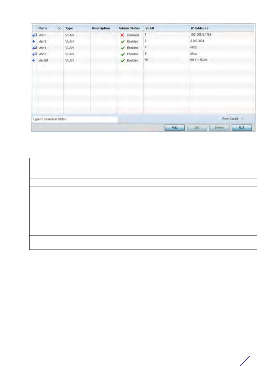
Device Configuration
Wireless Controller and Service Platform System Reference Guide 5 - 63
Figure 5-34 Profile Overrides - Virtual Interfaces screen
7 Review the following parameters unique to each virtual interface configuration to determine whether a
parameter override is warranted:
Once the configurations of existing virtual interfaces have been reviewed, determine whether a new interface
requires creation, or an existing virtual interface requires edit (override) or deletion.
8Select
Add to define a new virtual interface configuration, Edit to modify or override the configuration of an
existing virtual interface or Delete to permanently remove a selected virtual interface.
Name Displays the numeric ID of each listed virtual interface assigned when it
was created. The name is between 1 - 4094, and cannot be modified as
part of a virtual interface edit.
Type Displays the type of virtual interface for each listed interface.
Description Displays the description defined for the virtual interface when it was
either initially created or edited.
Admin Status A green check mark defines the listed virtual interface configuration as
active and enabled with its supported profile. A red “X” defines the virtual
interface as currently shut down. The interface status can be modified
when a new virtual interface is created or an existing one modified.
VLAN Displays the numerical VLAN ID associated with each listed interface.
IP Address Defines whether DHCP was used to obtain the primary IP address used by
the virtual interface configuration.
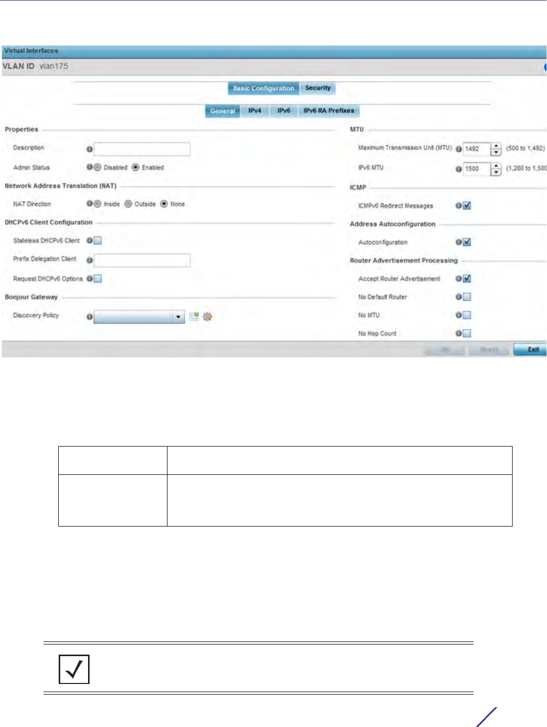
Device Configuration
Wireless Controller and Service Platform System Reference Guide 5 - 64
Figure 5-35 Profile Overrides - Virtual Interfaces Basic Configuration screen
The Basic Configuration screen displays by default regardless of a whether a new virtual interface is being
created or an existing one is being modified. Select the General tab if not selected by default.
9 If creating a new virtual interface, use the VLAN ID spinner control to define a numeric VLAN ID from 1 - 4094.
10 Define or override the following parameters from within the Properties field:
11 Define or override the Network Address Translation (NAT) direction.
Select either the Inside, Outside or None radio buttons.
•Inside - The inside network is transmitting data over the network its intended destination. On the way out,
the source IP address is changed in the header and replaced by the (public) IP address.
•Outside - Packets passing through the NAT on the way back to the managed LAN are searched against to
the records kept by the NAT engine. There the destination IP address is changed back to the specific internal
private class IP address in order to reach the LAN over the switch managed network.
•None - No NAT activity takes place. This is the default setting.
Description Provide or edit a description (up to 64 characters) for the virtual interface
that helps differentiate it from others with similar configurations.
Admin Status Either select the Disabled or Enabled radio button to define this interface’s
current status within the managed network. When set to Enabled, the
virtual interface is operational and available to the controller or service
platform. The default value is enabled.
NOTE: Refer to Setting the Profile’s NAT Configuration on page 8-186 for
instructions on creating a profile’s NAT configuration.

Device Configuration
Wireless Controller and Service Platform System Reference Guide 5 - 65
12 Set the following DHCPv6 Client Configuration. The Dynamic Host Configuration Protocol for IPv6 (DHCPv6)
provides a framework for passing configuration information.
13 Set the Bonjour Gateway settings for the virtual interface.Bonjour is Apple’s implementation of zero-
configuration networking (Zeroconf). Zeroconf is a group of technologies that include service discovery, address
assignment and hostname resolution. Bonjour locates devices such as printers, other computers and services
that these computers offer over a local network. Bonjour provides a general method to discover services on a
local area network (LAN). It allows users to set up a network without any configuration. Services such as
printers, scanners and file-sharing servers can be found using Bonjour. Bonjour only works within a single
broadcast domain. However, with special DNS configuration, it can be extended to find services across
broadcast domains.
14 Select the Bonjour Gateway discover policy from the drop-down menu. Select the Create icon to define a new
Bonjour Gateway policy configuration or select the Edit icon to modify an existing Bonjour Gateway policy
configuration.
15 Set the following MTU settings for the virtual interface:
16 Within the ICMP field, define whether ICMPv6 redirect messages are sent. Redirect requests data packets be
sent on an alternative route. This setting is enabled by default.
17 Within the Address Autoconfiguration field, define whether to configure IPv6 addresses on this virtual interface
based on the prefixes received in router advertisement messages. Router advertisements contain prefixes used
for link determination, address configuration and maximum hop limits. This setting is enabled by default.
Stateless DHCPv6
Client
Select this option to request information from the DHCPv6 server using
stateless DHCPv6. DHCPv6 is a networking protocol for configuring IPv6
hosts with IP addresses, IP prefixes or other configuration attributes
required on an IPv6 network. This setting is disabled by default.
Prefix Delegation
Client
Specify a 32 character maximum request prefix for prefix delegation from
a DHCPv6 server over this virtual interface. Devices use prefixes to
distinguish destinations that reside on-link from those reachable using a
router.
Request DHCPv6
Options
Select this option to request DHCPv6 options on this virtual interface.
DHCPv6 options provide configuration information for a node that must
be booted using the network rather than locally. This setting is disabled
by default.
Maximum
Transmission Unit
(MTU)
Set the PPPoE client maximum transmission unit (MTU) from 500 - 1,492.
The MTU is the largest physical packet size in bytes a network can
transmit. Any messages larger than the MTU are divided into smaller
packets before being sent. A PPPoE client should be able to maintain its
point-to-point connection for this defined MTU size. The default MTU is
1,492.
IPv6 MTU Set an IPv6 MTU for this virtual interface from 1,280 - 1,500. A larger MTU
provides greater efficiency because each packet carries more user data
while protocol overheads, such as headers or underlying per-packet
delays, remain fixed; the resulting higher efficiency means a slight
improvement in bulk protocol throughput. A larger MTU results in the
processing of fewer packets for the same amount of data. The default is
1,500.

Device Configuration
Wireless Controller and Service Platform System Reference Guide 5 - 66
18 Set the following Router Advertisement Processing settings for the virtual interface. Router advertisements are
periodically sent to hosts or sent in response to solicitation requests. The advertisement includes IPv6 prefixes
and other subnet and host information.
19 Select OK to save the changes. Select Reset to revert to the last saved configuration.
20 Select the IPv4 tab to set IPv4 settings for this virtual interface.
IPv4 is a connectionless protocol. It operates on a best effort delivery model that does not guarantee delivery
or assures proper sequencing or avoidance of duplicate delivery (unlike TCP).
Accept RA Enable this option to allow router advertisements over this virtual
interface. IPv6 hosts can configure themselves automatically when
connected to an IPv6 network using the neighbor discovery protocol via
ICMPv6 router discovery messages. When first connected to a network, a
host sends a link-local router solicitation multicast request for its
configuration parameters; routers respond to such a request with a router
advertisement packet that contains Internet layer configuration
parameters.This setting is enabled by default.
No Default Router Select this option to consider routers unavailable on this interface for
default router selection. This setting is disabled by default.
No MTU Select this option to not use the existing MTU setting for router
advertisements on this virtual interface. If the value is set to zero no MTU
options are sent. This setting is disabled by default.
No Hop Count Select this option to not use the hop count advertisement setting for
router advertisements on this virtual interface. This setting is disabled by
default.
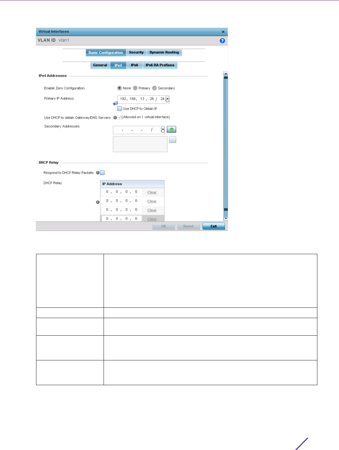
Device Configuration
Wireless Controller and Service Platform System Reference Guide 5 - 67
Figure 5-36 Virtual Interfaces - Basic Configuration screen - IPv4 tab
21 Set the following network information from within the IPv4 Addresses field:
Enable Zero
Configuration
Zero configuration can be a means of providing a primary or secondary IP
addresses for the virtual interface. Zero configuration (or zero config) is a
wireless connection utility included with Microsoft Windows XP and later
as a service dynamically selecting a network to connect based on a user's
preferences and various default settings. Zero config can be used instead
of a wireless network utility from the manufacturer of a computer's
wireless networking device. This value is set to None by default.
Primary IP Address Define the IP address for the VLAN associated Virtual Interface.
Use DHCP to Obtain
IP
Select this option to allow DHCP to provide the IP address for the Virtual
Interface. Selecting this option disables the Primary IP address field.
Use DHCP to obtain
Gateway/DNS
Servers
Select this option to allow DHCP to obtain a default gateway address and
DNS resource for one virtual interface. This setting is disabled by default
and only available when the Use DHCP to Obtain IP option is selected.
Secondary Addresses Use the Secondary Addresses parameter to define additional IP addresses
to associate with VLAN IDs. The address provided in this field is used if
the primary IP address is unreachable.
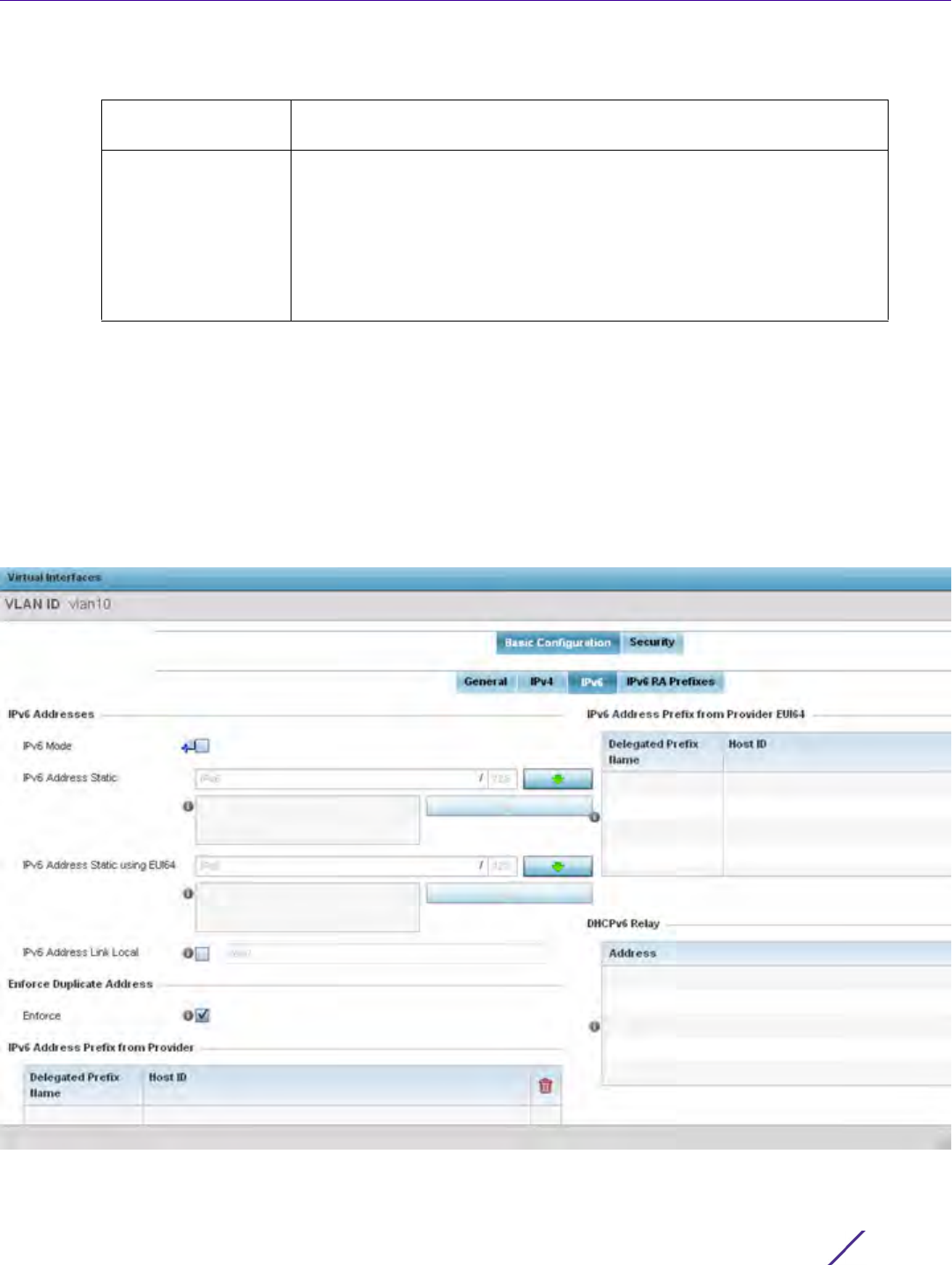
Device Configuration
Wireless Controller and Service Platform System Reference Guide 5 - 68
22 Refer to the DHCP Relay field to set the DHCP relay server configuration used with the Virtual Interface.
23 Select OK to save the changes to the IPv4 configuration. Select Reset to revert to the last saved configuration.
24 Select the IPv6 tab to set IPv6 settings for this virtual interface.
IPv6 is the latest revision of the Internet Protocol (IP) designed to replace IPv4. IPV6 provides enhanced
identification and location information for computers on networks routing traffic across the Internet. IPv6
addresses are composed of eight groups of four hexadecimal digits separated by colons. IPv6 hosts can
configure themselves automatically when connected to an IPv6 network using the neighbor discovery protocol
via ICMPv6 router discovery messages. When first connected to a network, a host sends a link-local router
solicitation multicast request for its configuration parameters; routers respond to such a request with a router
advertisement packet that contains Internet layer configuration parameters.
Figure 5-37 Virtual Interfaces - Basic Configuration screen - IPv6 tab
Respond to DHCP
Relay Packets
Select this option to allow the onboard DHCP server to respond to relayed
DHCP packets on this interface. This setting is disabled by default.
DHCP Relay Provide IP addresses for DHCP server relay resources. DHCP relays
exchange messages between a DHCPv6 server and client. A client and
relay agent exist on the same link. When A DHCP request is received from
the client, the relay agent creates a relay forward message and sends it to
a specified server address. If no addresses are specified, the relay agent
forwards the message to all DHCP server relay multicast addresses. The
server creates a relay reply and sends it back to the relay agent. The relay
agent then sends back the response to the client.
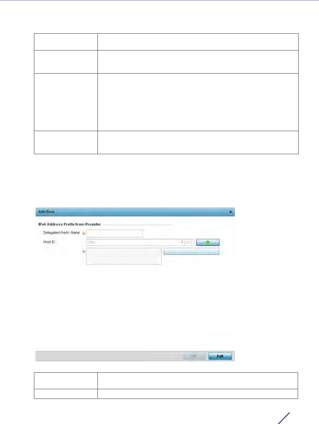
Device Configuration
Wireless Controller and Service Platform System Reference Guide 5 - 69
25 Refer to the IPv6 Addresses field to define how IP6 addresses are created and utilized.
26 Enable the Enforce Duplicate Address option to enforce duplicate address protection when any wired port is
connected and in a forwarding state. This option is enabled by default.
27 Refer to the IPv6 Address Prefix from Provider table to create IPv6 format prefix shortcuts as supplied by an
ISP.
28 Select + Add Row to launch a sub screen wherein a new delegated prefix name and host ID can be defined.
Figure 5-38 Virtual Interfaces - Basic Configuration screen - IPv6 tab - Add Address Prefix from Provider
IPv6 Mode Select this option to enable IPv6 support on this virtual interface. IPv6 is
disabled by default.
IPv6 Address Static Define up to 15 global IPv6 IP addresses that can created statically. IPv6
addresses are represented as eight groups of four hexadecimal digits
separated by colons.
IPv6 Address Static
using EUI64
Optionally set up to 15 global IPv6 IP addresses (in the EUI-64 format)
that can created statically. The IPv6 EUI-64 format address is obtained
through a 48-bit MAC address. The MAC is initially separated into two 24-
bits, with one being an OUI (Organizationally Unique Identifier) and the
other being client specific. A 16-bit 0xFFFE is then inserted between the
two 24-bits for the 64-bit EUI address. IEEE has chosen FFFE as a
reserved value which can only appear in EUI-64 generated from the an
EUI-48 MAC address.
IPv6 Address Link
Local
Provide the IPv6 local link address. IPv6 requires a link local address
assigned to every interface the IPv6 protocol is enabled, even when one
or more routable addresses are assigned.
Delegated Prefix
Name
Enter a 32 character maximum name for the IPv6 address prefix from
provider.
Host ID Define the subnet ID, host ID and prefix length.
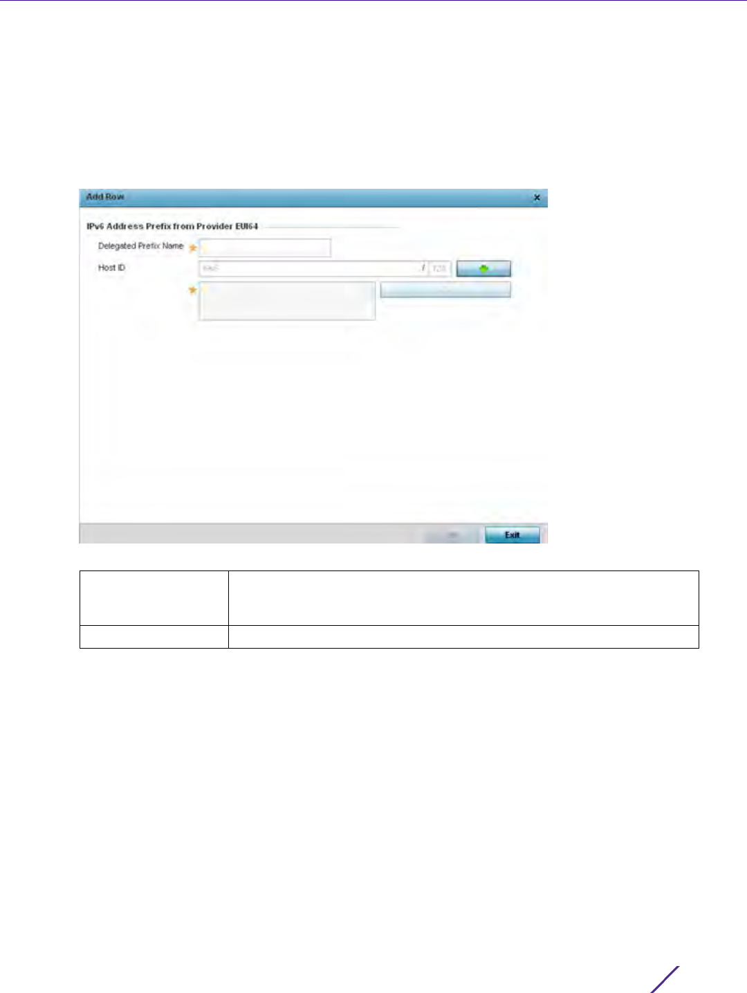
Device Configuration
Wireless Controller and Service Platform System Reference Guide 5 - 70
29 Select OK to save the changes to the new IPv6 prefix from provider. Select Exit to close the screen without
saving the updates.
30 Refer to the IPv6 Address Prefix from Provider EUI64 table to set an (abbreviated) IP address prefix in EUI64
format.
31 Select + Add Row to launch a sub screen wherein a new delegated prefix name and host ID can be defined in
EUI64 format.
Figure 5-39 Virtual Interfaces - Basic Configuration screen - IPv6 tab - Add Address Prefix from Provider EUI64
32 Select OK to save the changes to the new IPv6 prefix from provider in EUI64 format. Select Exit to close the
screen without saving the updates.
33 Refer to the DHCPv6 Relay table to set the address and interface of the DHCPv6 relay.
The DHCPv6 relay enhances an extended DHCP relay agent by providing support in IPv6. DHCP relays
exchange messages between a DHCPv6 server and client. A client and relay agent exist on the same link.
When A DHCP request is received from the client, the relay agent creates a relay forward message and sends it
to a specified server address. If no addresses are specified, the relay agent forwards the message to all DHCP
server relay multicast addresses. The server creates a relay reply and sends it back to the relay agent. The relay
agent then sends back the response to the client.
34 Select + Add Row to launch a sub screen wherein a new DHCPv6 relay address and interface VLAN ID can be
set.
Delegated Prefix
Name
Enter a 32 character maximum name for the IPv6 prefix from provider in
EUI format. Using EUI64, a host can automatically assign itself a unique
64-bit IPv6 interface identifier without manual configuration or DHCP.
Host ID Define the subnet ID and prefix length.

Device Configuration
Wireless Controller and Service Platform System Reference Guide 5 - 71
Figure 5-40 Virtual Interfaces - Basic Configuration screen - IPv6 tab - Add DHCPv6 Relay
35 Select OK to save the changes to the DHCPv6 relay configuration. Select Exit to close the screen without saving
the updates.
36 Select the IPv6 RA Prefixes tab.
Address Enter an address for the DHCPv6 relay. These DHCPv6 relay receive
messages from DHCPv6 clients and forward them to DHCPv6 servers. The
DHCPv6 server sends responses back to the relay, and the relay then
sends these responses to the client on the local network.
Interface Select this option to enable a spinner control to define a VLAN ID from 1 -
4,094 used as the virtual interface for the DHCPv6 relay. The interface
designation is only required for link local and multicast addresses. A local
link address is a locally derived address designed for addressing on a
single link for automatic address configuration, neighbor discovery or
when no routing resources are available.
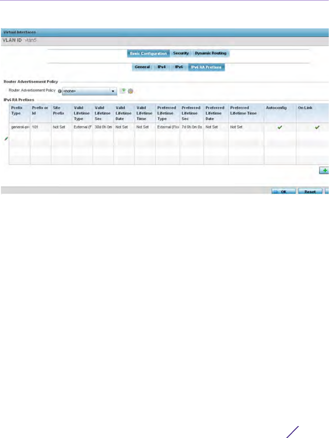
Device Configuration
Wireless Controller and Service Platform System Reference Guide 5 - 72
Figure 5-41 Virtual Interfaces - Basic Configuration screen - IPv6 RA Prefixes tab
37 Use the Router Advertisement Policy drop-down menu to select and apply a policy to the virtual interface.
Router advertisements are periodically sent to hosts or sent in response to solicitation requests. The
advertisement includes IPv6 prefixes and other subnet and host information.
38 Review the configurations of existing IPv6 advertisement policies. If needed select + Add Row to define the
configuration of an additional IPv6 RA prefix.

Device Configuration
Wireless Controller and Service Platform System Reference Guide 5 - 73
Figure 5-42 Virtual Interfaces - Basic Configuration screen - Add IPv6 RA Prefix
39 Set the following IPv6 RA Prefix settings:
Prefix Type Set the prefix delegation type used with this configuration. Options
include, Prefix, and prefix-from-provider. The default setting is Prefix. A
prefix allows an administrator to associate a user defined name to an IPv6
prefix. A provider assigned prefix is made available from an Internet
Service Provider (ISP) to automate the process of providing and informing
the prefixes used.
Prefix or ID Set the actual prefix or ID used with the IPv6 router advertisement.
Site Prefix The site prefix is added into a router advertisement prefix. The site
address prefix signifies the address is only on the local link.
Valid Lifetime Type Set the lifetime for the prefix's validity. Options include External (fixed),
decrementing and infinite. If set to External (fixed), just the Valid Lifetime
Sec setting is enabled to define the exact time interval for prefix validity. If
set to decrementing, use the lifetime date and time settings to refine the
prefix expiry period. If the value is set for infinite, no additional date or
time settings are required for the prefix and the prefix will not expire. The
default setting is External (fixed).
Valid Lifetime Sec If the lifetime type is set to External (fixed), set the Seconds, Minutes,
Hours or Days value used to measurement criteria for the prefix's
expiration. 30 days, 0 hours, 0 minutes and 0 seconds is the default
lifetime.
Valid Lifetime Date If the lifetime type is set to External (fixed), set the date in
MM/DD/YYYY format for the expiration of the prefix.

Device Configuration
Wireless Controller and Service Platform System Reference Guide 5 - 74
40 Select OK to save the changes to the IPv6 RA prefix configuration. Select Exit to close the screen without
saving the updates.
41 Select OK to save the changes and overrides. Select Reset to revert to the last saved configuration.
42 Select the Security tab.
Valid Lifetime Time If the lifetime type is set to decrementing, set the time for the prefix's
validity.
Preferred Lifetime
Type
Set the administrator preferred lifetime for the prefix's validity. Options
include External (fixed), decrementing and infinite. If set to External
(fixed), just the Valid Lifetime Sec setting is enabled to define the exact
time interval for prefix validity. If set to decrementing, use the lifetime
date and time settings to refine the prefix expiry period. If the value is set
for infinite, no additional date or time settings are required for the prefix
and the prefix will not expire. The default setting is External (fixed).
Preferred Lifetime
Sec
If the administrator preferred lifetime type is set to External (fixed), set
the Seconds, Minutes, Hours or Days value used to measurement criteria
for the prefix's expiration. 30 days, 0 hours, 0 minutes and 0 seconds is
the default lifetime.
Preferred Lifetime
Date
If the administrator preferred lifetime type is set to External (fixed), set
the date in MM/DD/YYYY format for the expiration of the prefix.
Preferred Lifetime
Time
If the preferred lifetime type is set to decrementing, set the time for the
prefix's validity.
Autoconfig Autoconfiguration includes generating a link-local address, global
addresses via stateless address autoconfiguration and duplicate address
detection to verify the uniqueness of the addresses on a link. This setting
is enabled by default.
On Link Select this option to keep the IPv6 RA prefix on the local link. The default
setting is enabled.
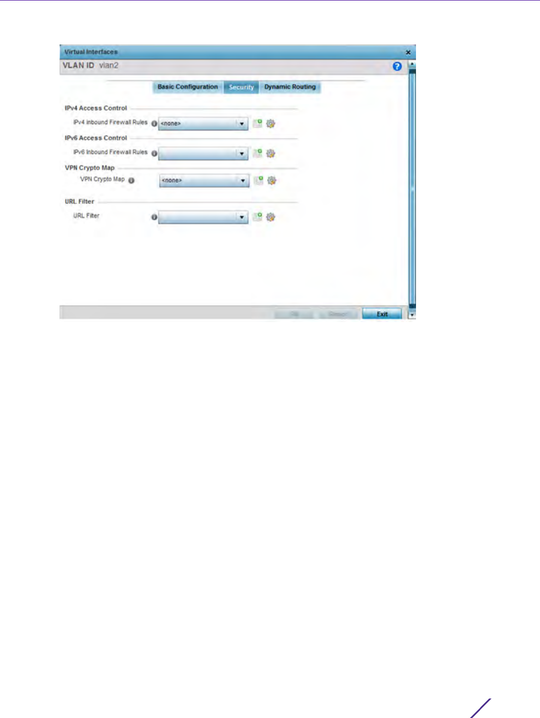
Device Configuration
Wireless Controller and Service Platform System Reference Guide 5 - 75
Figure 5-43 Profile Overrides - Virtual Interfaces Security screen
43 Use the IPv4 Inbound Firewall Rules drop down menu to select the IPv4 specific inbound firewall rules to apply
to this profile’s virtual interface configuration. Select the Create icon to define a new IPv4 firewall rule
configuration or select the Edit icon to modify an existing configuration.
IPv4 is a connectionless protocol for packet switched networking. IPv4 operates as a best effort delivery
method, since it does not guarantee delivery, and does not ensure proper sequencing or duplicate delivery
(unlike (TCP).
IPv4 and IPv6 are different enough to warrant separate protocols. IPv6 devices can alternatively use stateless
address autoconfiguration. IPv4 hosts can use link local addressing to provide local connectivity.
44 Use the IPv6 Inbound Firewall Rules drop down menu to select the IPv6 specific inbound firewall rules to apply
to this profile’s virtual interface configuration. Select the Create icon to define a new IPv6 firewall rule
configuration or select the Edit icon to modify an existing configuration.
IPv6 is the latest revision of the Internet Protocol (IP) replacing IPv4. IPV6 provides enhanced identification and
location information for systems routing traffic across the Internet. IPv6 addresses are composed of eight
groups of four hexadecimal digits separated by colons.
45 Use the VPN Crypto Map drop-down menu to select or override the Crypto Map configuration applied to this
virtual interface.
Crypto Map entries are sets of configuration parameters for encrypting packets that pass through the VPN
Tunnel. If a Crypto Map configuration does not exist suiting the needs of this virtual interface, select the Create
icon to define a new Crypto Map configuration or the Edit icon to modify an existing configuration. For more
information, see Overriding a Profile’s VPN Configuration on page 5-207.
46 Use the URL Filter drop-down menu to select or override the URL Filter configuration applied to this virtual
interface. URL filtering is used to restrict access to undesirable resources on the Internet.
47 Select the Dynamic Routing tab (if available with your controller or service platform).
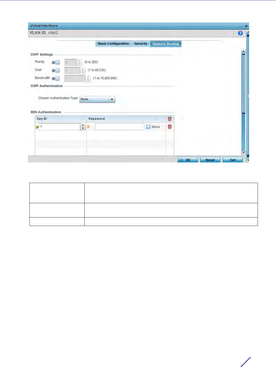
Device Configuration
Wireless Controller and Service Platform System Reference Guide 5 - 76
Figure 5-44 Profile Overrides - Virtual Interfaces Security screen
48 Define or override the following parameters from within the OSPF Settings field:
49 Select the authentication type from the Chosen Authentication Type drop-down used to validate credentials
within the OSPF dynamic route. Options include simple-password, message-digest, null and None. The default
value is None.
50 Select the + Add Row button at the bottom of the MD5 Authentication table to add the Key ID and Password
used for an MD5 validation of authenticator credentials. Use the spinner control to set the OSPF message digest
authentication key ID. The available range is from 1 - 255. The password is the OSPF key either displayed as
series or asterisks or in plain text (by selecting Show).
51 Select the OK button located at the bottom right of the screen to save the changes and overrides to the
Dynamic Routing screen. Select Reset to revert to the last saved configuration.
5.2.7.3 Port Channel Override Configuration
Profile Interface Override Configuration
Profiles can utilize customized port channel configurations as part of their interface settings. Existing port channel
profile configurations can be overridden as the become obsolete for specific device deployments.
To define or override a port channel configuration on a profile:
Priority Select this option to set the OSPF priority used to select the network
designated route. Use the spinner control to set the value from
0 - 255.
Cost Select this option to set the cost of the OSPF interface. Use the spinner
control to set the value from 1 - 65,535.
Bandwidth Set the OSPF interface bandwidth (in Kbps) from 1 - 10,000,000.
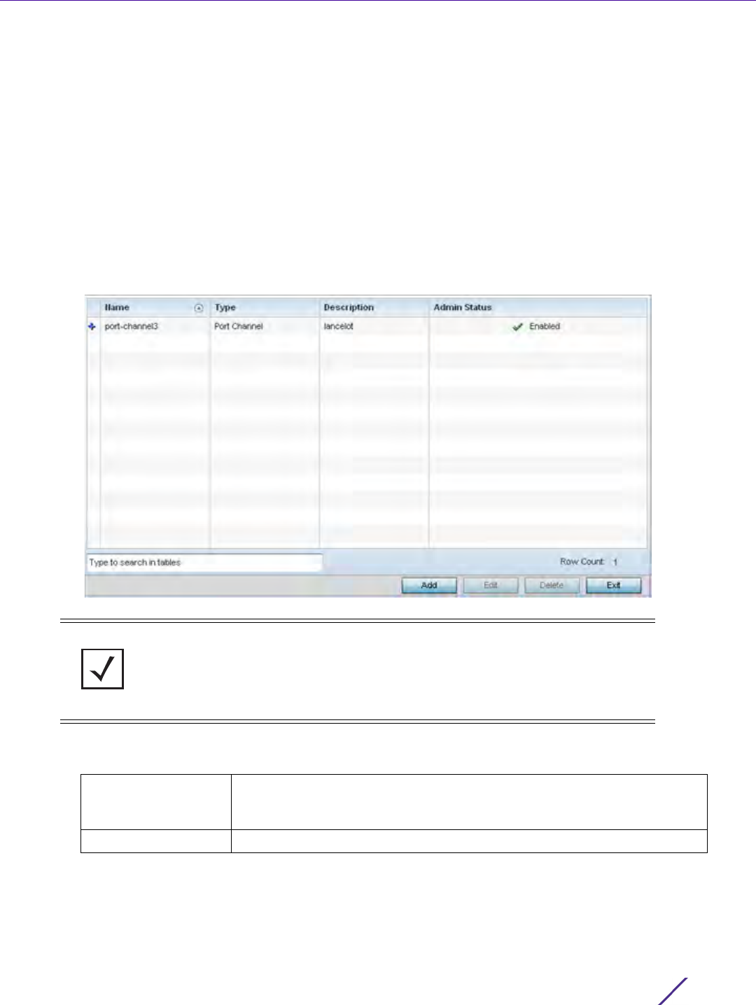
Device Configuration
Wireless Controller and Service Platform System Reference Guide 5 - 77
1 Select the Configuration tab from the Web UI.
2Select
Devices from the Configuration tab.
The Device Configuration screen displays a list of managed devices or peer controllers, service platforms or
Access Points.
3 Select a target device (by double-clicking it) from amongst those displayed within the Device Configuration
screen.
Devices can also be selected directly from the Device Browser in the lower, left-hand, side of the UI.
4Select
Profile Overrides from the Device menu to expand it into sub menu options.
5Select
Interface to expand its sub menu options.
6Select
Port Channels.
Figure 5-45 Profile Overrides - Port Channels screen
7 Refer to the following to review existing port channel configurations and status to determine whether a
parameter requires an override:
NOTE: A blue override icon (to the left of a parameter) defines the parameter as
having an override applied. To remove an override go to the Basic Configuration
section of the device and click the Clear Overrides button. This removes all
overrides from the device.
Name Displays the port channel’s numerical identifier assigned when it was
created. The numerical name cannot be modified as part of the edit
process.
Type Displays whether the type is port channel.
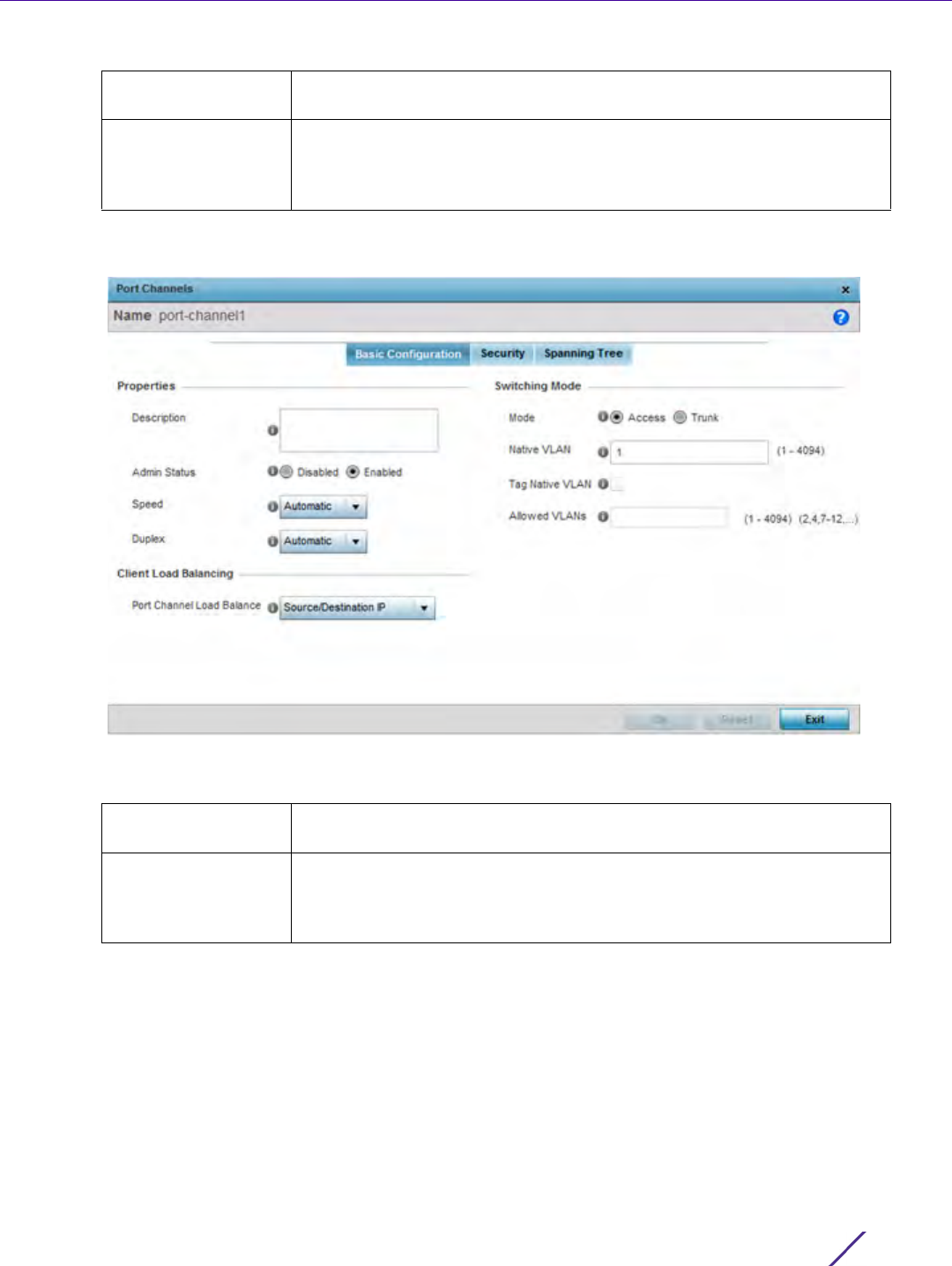
Device Configuration
Wireless Controller and Service Platform System Reference Guide 5 - 78
8 To edit or override the configuration of an existing port channel, select it from amongst those displayed and
select the Edit button. The port channel Basic Configuration screen displays by default.
Figure 5-46 Profile Overrides - Port Channels Basic Configuration screen
9 Set or override the following port channel Properties:
Description Lists a a short description (64 characters maximum) describing the port
channel or differentiating it from others with similar configurations.
Admin Status A green check mark defines the listed port channel as active and currently
enabled with the profile. A red “X” defines the port channel as currently
disabled and not available for use. The interface status can be modified
with the port channel configuration as required.
Description Enter a description for the controller or service platform port channel (64
characters maximum).
Admin Status Select the Enabled radio button to define this port channel as active to
the profile it supports. Select the Disabled radio button to disable this port
channel configuration in the profile. It can be activated at any future time
when needed. The default setting is enabled.

Device Configuration
Wireless Controller and Service Platform System Reference Guide 5 - 79
10 Use the Port Channel Load Balance drop-down menu from the Client Load Balancing section to define whether
port channel load balancing is conducted using a Source/Destination IP or a Source/Destination MAC. Source/
Destination IP is the default setting.
11 Define or override the following Switching Mode parameters to apply to the port channel configuration:
Speed Select the speed at which the port channel can receive and transmit data.
Select either 10 Mbps, 100 Mbps or 1000 Mbps to establish a 10, 100 or
1000 Mbps data transfer rate for the selected half duplex or full duplex
transmission. These options are not available if Auto is selected. Select
Automatic to allow the port channel to automatically exchange
information about data transmission speeds and duplex capabilities. Auto
negotiation is helpful in an environment where different devices are
connected and disconnected on a regular basis. Automatic is the default
setting.
Duplex Select either half, full or automatic as the duplex option. Select Half
duplex to send data over the port channel, then immediately receive data
from the same direction in which the data was transmitted. Like a full-
duplex transmission, a half-duplex transmission can carry data in both
directions, just not at the same time. Select Full duplex to transmit data to
and from the port channel at the same time. Using full duplex, the port
channel can send data while receiving data as well. Select Automatic to
enable to the controller or service platform to dynamically duplex as port
channel performance needs dictate. Automatic is the default setting.
Mode Select either the Access or Trunk radio button to set the VLAN switching
mode over the port channel. If Access is selected, the port channel
accepts packets only from the native VLAN. Frames are forwarded
untagged with no 802.1Q header. All frames received on the port are
expected as untagged and are mapped to the native VLAN. If the mode is
set to Trunk, the port channel allows packets from a list of VLANs you
add to the trunk. A port channel configured as Trunk supports multiple
802.1Q tagged VLANs and one Native VLAN which can be tagged or
untagged. Access is the default setting.
Native VLAN Use the spinner control to define a numerical Native VLAN ID from
1 - 4094. The native VLAN allows an Ethernet device to associate
untagged frames to a VLAN when no 802.1Q frame is included in the
frame. Additionally, the native VLAN is the VLAN untagged traffic will be
directed over when using trunk mode. The default value is 1.
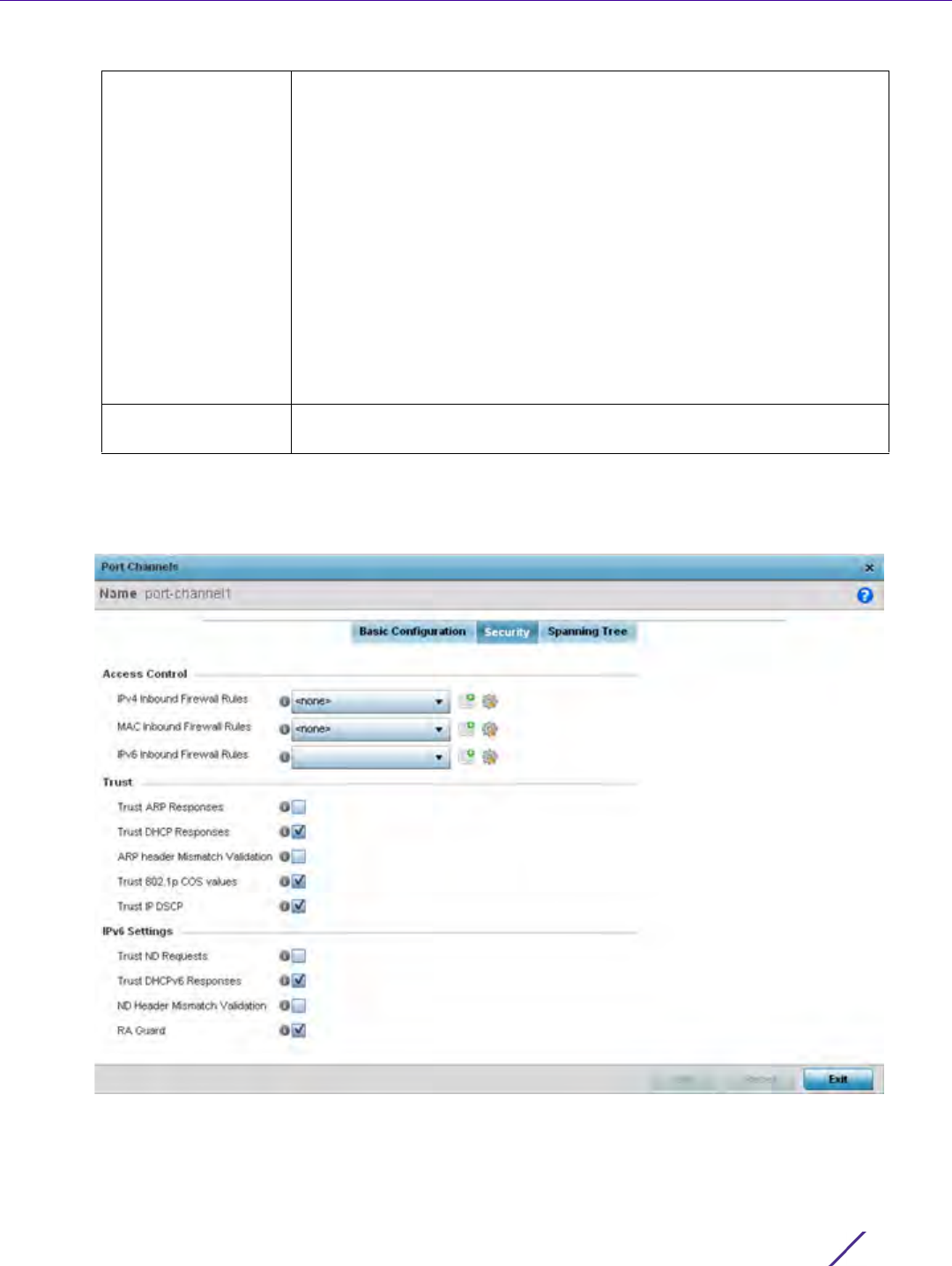
Device Configuration
Wireless Controller and Service Platform System Reference Guide 5 - 80
12 Select OK to save the changes and overrides to the port channel Basic Configuration. Select Reset to revert to
the last saved configuration.
13 Select the Security tab.
Figure 5-47 Profile Overrides - Port Channels Security screen
14 Refer to the Access Control section. As part of the port channel’s security configuration, Inbound IPv4 IP, IPv6
IP and MAC address firewall rules are required.
Tag the Native VLAN Select this option to tag the native VLAN. Controllers and service
platforms support the IEEE 802.1Q specification for tagging frames and
coordinating VLANs between devices. IEEE 802.1Q adds four bytes to
each frame identifying the VLAN ID for upstream devices that the frame
belongs. If the upstream Ethernet device does not support IEEE 802.1Q
tagging, it does not interpret the tagged frames. When VLAN tagging is
required between devices, both devices must support tagging and be
configured to accept tagged VLANs. When a frame is tagged, a 12 bit
frame VLAN ID is added to the 802.1Q header, so upstream Ethernet
devices know which VLAN ID the frame belongs to. The device reads the
12 bit VLAN ID and forwards the frame to the appropriate VLAN. When a
frame is received with no 802.1Q header, the upstream device classifies
the frame using the default or native VLAN assigned to the Trunk port.
The native VLAN allows an Ethernet device to associate untagged frames
to a VLAN when no 802.1Q frame is included in the frame. This setting is
disabled by default.
Allowed VLANs Selecting Trunk as the mode enables the Allowed VLANs parameter. Add
VLANs that exclusively send packets over the port channel.

Device Configuration
Wireless Controller and Service Platform System Reference Guide 5 - 81
15 Use the drop-down menus to select the firewall rules to apply to this profile’s Ethernet port configuration. The
firewall inspects IP and MAC traffic flows and detects attacks typically not visible to traditional wired firewall
appliances
16 Use the IPv4 Inbound Firewall Rules drop down menu to select the IPv4 specific firewall rules to apply to this
profile’s port channel configuration. IPv4 is a connectionless protocol for packet switched networking. IPv4
operates as a best effort delivery method, as it does not guarantee delivery, and does not ensure proper
sequencing or duplicate delivery (unlike (TCP). IPv4 hosts can use link local addressing to provide local
connectivity.
17 Use the IPv6 Inbound Firewall Rules drop down menu to select the IPv6 specific firewall rules to apply to this
profile’s port channel configuration. IPv6 is the latest revision of the Internet Protocol (IP) designed to replace
IPv4. IPV6 provides enhanced identification and location information for computers on networks routing traffic
across the Internet. IPv6 addresses are composed of eight groups of four hexadecimal digits separated by
colons.
18 If a firewall rule does not exist suiting the data protection needs of the target port channel configuration, select
the Create icon to define a new rule configuration or the Edit icon to modify an existing firewall rule
configuration.
19 Refer to the Trust section to define or override the following:
20 Refer to the IPv6 Settings field to define the following:
Trust ARP Responses Select this option to enable ARP trust on this port channel. ARP packets
received on this port are considered trusted, and information from these
packets is used to identify rogue devices. The default value is disabled.
Trust DHCP Responses Select this option to enable DHCP trust. If enabled, only DHCP
responses are trusted and forwarded on this port channel, and a DHCP
server can be connected only to a DHCP trusted port. The default value
is enabled.
ARP header Mismatch
Validation
Select this option to enable a source MAC mismatch check in both the
ARP and Ethernet header. The default value is enabled.
Trust 802.1p COS
values
Select this option to enable 802.1p COS values on this port channel. The
default value is enabled.
Trust IP DSCP Select this option to enable IP DSCP values on this port channel. The
default value is disabled.
Trust ND Requests Select the check box to enable neighbor discovery (ND) request trust on
this port channel (neighbor discovery requests received on this port are
considered trusted). Neighbor discovery allows the discovery of an
adjacent device’s MAC addresses, similar to Address Resolution Protocol
(ARP) on Ethernet in IPv4. The default value is disabled.
Trust DHCPv6
Responses
Select the check box to enable DHCPv6 trust. If enabled, only DHCPv6
responses are trusted and forwarded on this port channel, and a
DHCPv6 server can be connected only to a trusted port. The default
value is enabled.
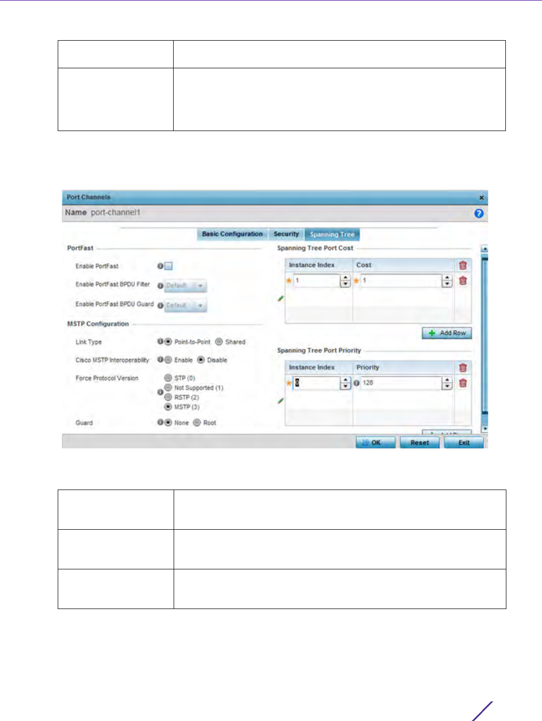
Device Configuration
Wireless Controller and Service Platform System Reference Guide 5 - 82
21 Select OK to save the changes and overrides to the security configuration. Select Reset to revert to the last
saved configuration.
22 Select the Spanning Tree tab.
Figure 5-48 Profile Overrides - Port Channels Spanning Tree screen
23 Define or override the following PortFast parameters for the port channel’s MSTP configuration:
ND header Mismatch
Validation
Select the check box to enable a mismatch check for the source MAC in
both the ND header and link layer option. The default value is disabled.
RA Guard Select this option to allow router advertisements or IPv6 redirects from
this port. Router advertisements are periodically sent to hosts or sends
in response to solicitation requests. The advertisement includes IPv6
prefixes and other subnet and host information.This setting is enabled
by default.
Enable PortFast Select this option to enable drop-down menus for both the Enable
Portfast BPDU Filter and Enable Portfast BPDU guard options for the
port. This setting is disabled by default.
Enable PortFast BPDU
Filter
Enable PortFast to invoke a BPDU filter for this portfast enabled port
channel. Enabling the BPDU filter feature ensures this port channel does
not transmit or receive any BPDUs.
Enable PortFast BPDU
Guard
Enable PortFast to invoke a BPDU guard for this portfast enabled port
channel. Enabling the BPDU Guard feature means this port will
shutdown on receiving a BPDU. Hence no BPDUs are processed.

Device Configuration
Wireless Controller and Service Platform System Reference Guide 5 - 83
24 Set or override the following MSTP Configuration parameters for the port channel:
25 Refer to the Spanning Tree Port Cost table.
26 Define or override an Instance Index using the spinner control and then set the Cost. The default path cost
depends on the user defined port speed. The cost helps determine the role of the port channel in the MSTP
network.
The designated cost is the cost for a packet to travel from this port to the root in the MSTP configuration. The
slower the media, the higher the cost.
27 Refer to the Spanning Tree Port Priority table.
Define or override an Instance Index using the spinner control, then set the Priority. The lower the priority, the
greater likelihood of the port becoming a designated port.
Enable as Edge Port Select this option to define this port as an edge port. Using an edge
(private) port, you can isolate devices to prevent connectivity over this
port channel. This setting is disabled by default.
Link Type Select either the Point-to-Point or Shared radio button. Selecting Point-
to-Point indicates the port should be treated as connected to a point-to-
point link. Selecting Shared indicates this port should be treated as
having a shared connection. A port connected to a hub is on a shared
link, while one connected to a controller or service platform is a point-
to-point link. Point-to-Point is the default setting.
Cisco MSTP
Interoperability
Select either the Enable or Disable radio buttons. This enables
interoperability with Cisco’s version of MSTP, which is incompatible with
standard MSTP. This setting is disabled by default.
Force Protocol Version Sets the protocol version to either STP(0), Not Supported(1), RSTP(2) or
MSTP(3). MSTP is the default setting.
Guard Determines whether the port channel enforces root bridge placement.
Setting the guard to Root ensures the port is a designated port.
Typically, each guard root port is a designated port, unless two or more
ports (within the root bridge) are connected together. If the bridge
receives superior (BPDUs) on a guard root-enabled port, the guard root
moves the port to a root-inconsistent STP state. This state is equivalent
to a listening state. No data is forwarded across the port. Thus, the
guard root enforces the root bridge position.
Speed Default Path Cost
<=100000 bits/sec 200000000
<=1000000 bits/sec 20000000
<=10000000 bits/sec 2000000
<=100000000 bits/sec 200000
<=1000000000 bits/sec 20000
<=10000000000 bits/sec 2000
<=100000000000 bits/
sec
200
<=1000000000000 bits/
sec
20
>1000000000000 bits/
sec
2

Device Configuration
Wireless Controller and Service Platform System Reference Guide 5 - 84
28 Select + Add Row as needed to include additional indexes.
29 Select OK to save the changes and overrides made to the Ethernet Port Spanning Tree configuration. Select
Reset to revert to the last saved configuration.
5.2.7.4 VM Interface Override Configuration
Profile Interface Override Configuration
WiNG provides a dataplane bridge for external network connectivity for Virtual Machines (VMs). VM Interfaces
define which IP address is associated with each VLAN ID the service platform is connected to and enables remote
service platform administration. Each custom VM can have up to a maximum of two VM interfaces. Each VM
interface can be mapped to one of sixteen VMIF ports on the dataplane bridge. This mapping determines the
destination for service platform routing.
By default, VM interfaces are internally connected to the dataplane bridge via VMIF1. VMIF1 is an untagged port
providing access to VLAN 1 to support the capability to connect the VM interfaces to any of the VMIF ports. This
provides the flexibility to move a VM interface onto different VLANs as well as configure specific firewall and QOS
rules.
To define or override a VM interfaces configuration on a profile:
1 Select the Configuration tab from the Web UI.
2Select
Devices from the Configuration tab.
The Device Configuration screen displays a list of managed devices or peer controllers, service platforms or
Access Points.
3 Select a target device (by double-clicking it) from amongst those displayed within the Device Configuration
screen.
Devices can also be selected directly from the Device Browser in the lower, left-hand, side of the UI.
4Select
Profile Overrides from the Device menu to expand it into sub menu options.
5Select
Interface to expand its sub menu options.
6Select
VM Interfaces.
The VM Interfaces screen displays.
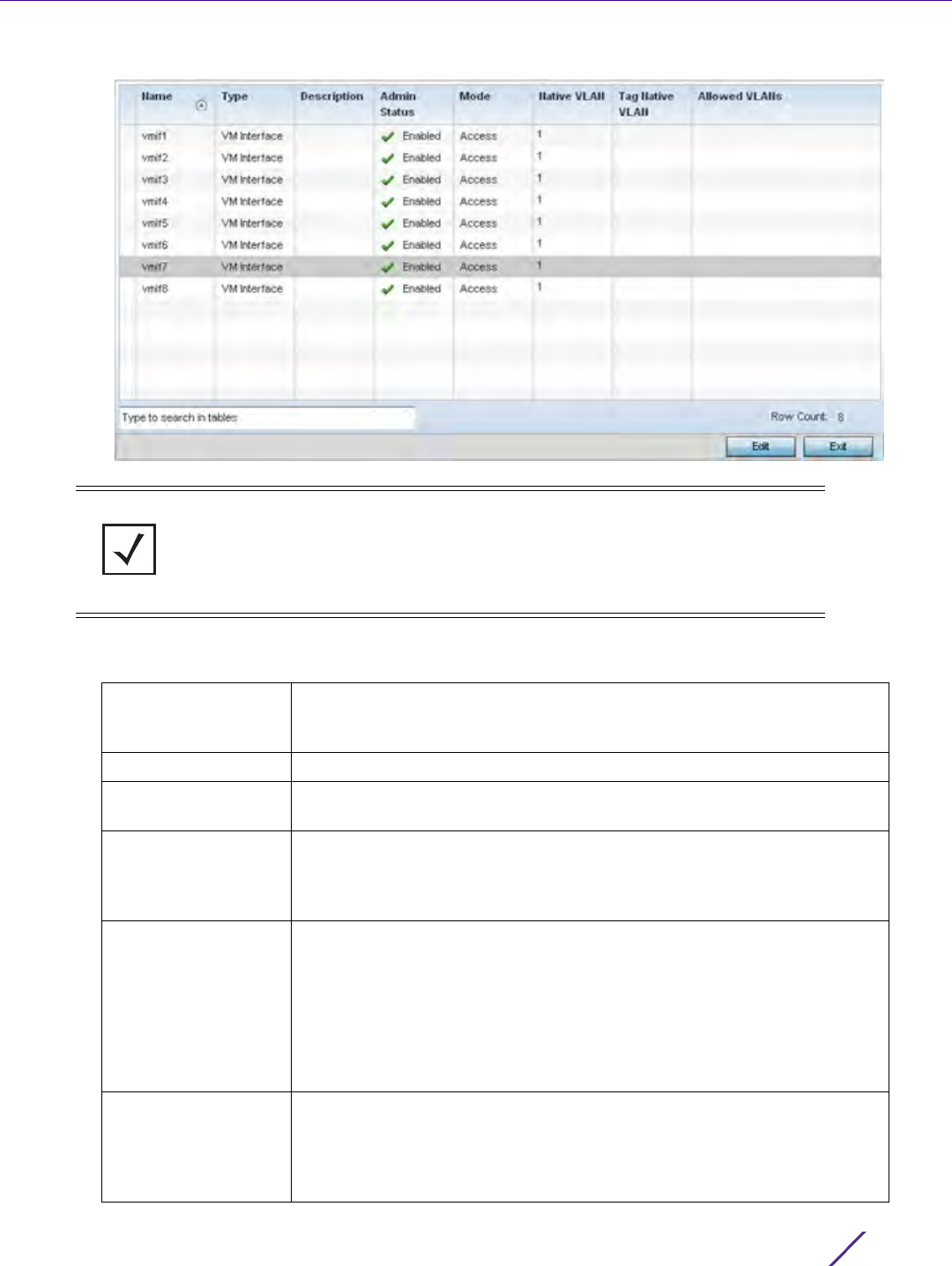
Device Configuration
Wireless Controller and Service Platform System Reference Guide 5 - 85
Figure 5-49 Profile Overrides - VM Interfaces screen
7 Refer to the following to review existing port channel configurations and status to determine whether a
parameter requires an override:
NOTE: A blue override icon (to the left of a parameter) defines the parameter as
having an override applied. To remove an override go to the Basic Configuration
section of the device and click the Clear Overrides button. This removes all
overrides from the device.
Name Displays the VM interface numerical identifier assigned when it was
created. The numerical name cannot be modified as part of the edit
process.
Type Displays whether the type is a VM interface.
Description Lists a short description (64 characters maximum) describing the VM
interface or differentiating it from others with similar configurations.
Admin Status A green check mark defines the listed VM interface as active and currently
enabled with the profile. A red “X” defines the VM interface as currently
disabled and not available for use. The interface status can be modified
with the VM interface Basic Configuration screen as required.
Mode Displays the layer 3 mode of the VM interface as either Access or Trunk
(as defined within the VM Interfaces Basic Configuration screen). If Access
is selected, the listed VM interface accepts packets only from the native
VLAN. Frames are forwarded untagged with no 802.1Q header. All frames
received on the port are expected as untagged and mapped to the native
VLAN. If set to Trunk, the port allows packets from a list of VLANs added
to the trunk. A VM interface configured as Trunk supports multiple 802.1Q
tagged VLANs and one Native VLAN which can be tagged or untagged.
Native VLAN Lists the numerical VLAN ID (1 - 4094) set for the native VLAN. The
native VLAN allows a VM interface to associate untagged frames to a
VLAN when no 802.1Q frame is included in the frame. Additionally, the
native VLAN is the VLAN untagged traffic is directed over when using a
VM interface in trunk mode.
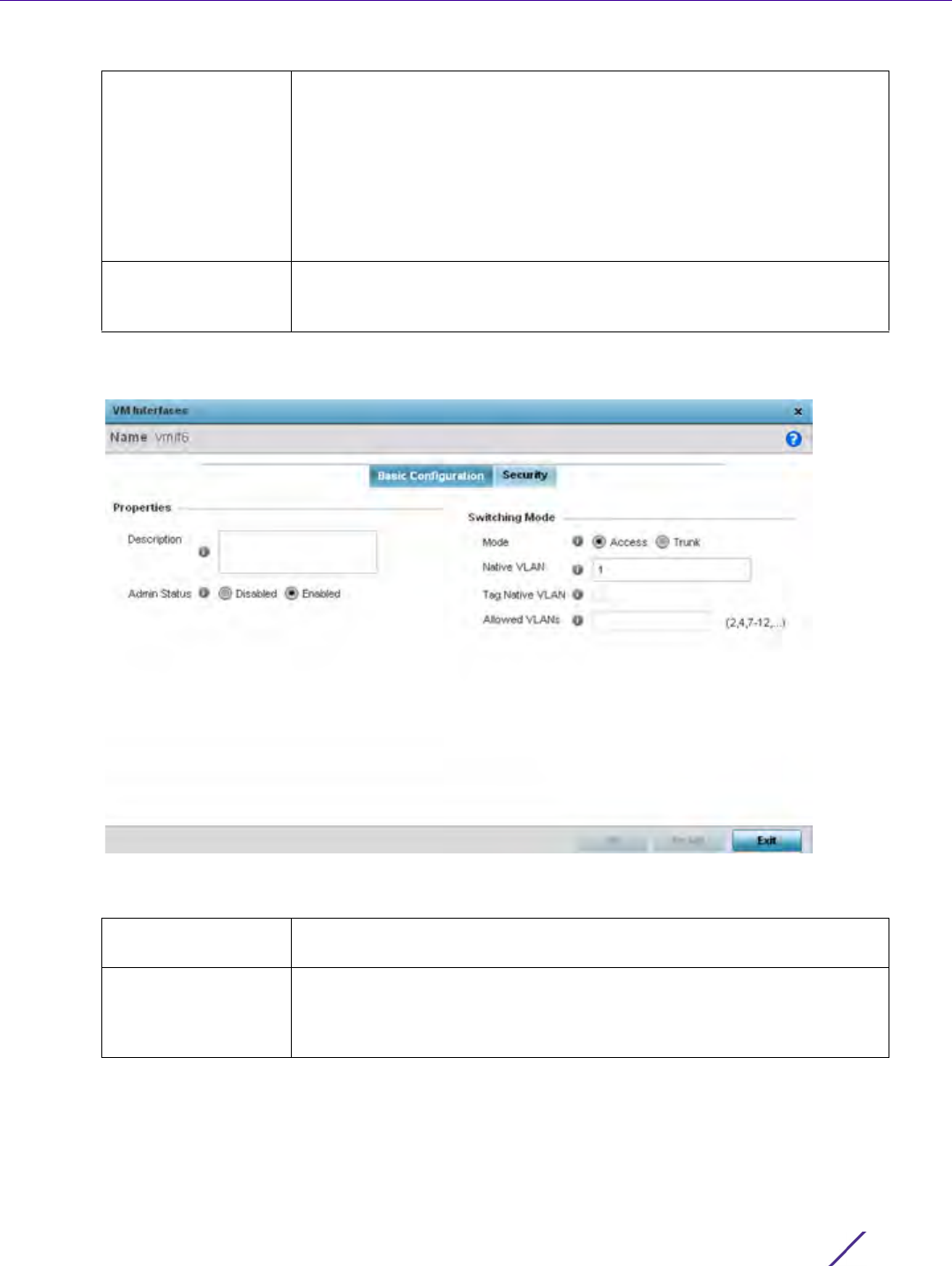
Device Configuration
Wireless Controller and Service Platform System Reference Guide 5 - 86
8 To edit or override the configuration of an existing VM interface, select it from amongst those displayed and
select the Edit button. The VM Interfaces Basic Configuration screen displays by default.
Figure 5-50 Profile Overrides - VM Interfaces Basic Configuration screen
9 Set or override the following VM Interface Properties:
Tag Native VLAN A green check mark defines the native VLAN as tagged. A red “X” defines
the native VLAN as untagged. When a frame is tagged, the 12 bit frame
VLAN ID is added to the 802.1Q header so upstream VM interface ports
know which VLAN ID the frame belongs to. The device reads the 12 bit
VLAN ID and forwards the frame to the appropriate VLAN. When a frame
is received with no 802.1Q header, the upstream VM interface classifies the
frame using the default or native VLAN assigned to the Trunk port. A
native VLAN allows a VM interface to associate untagged frames to a
VLAN when no 802.1Q frame is included in the frame.
Allowed VLANs Displays those VLANs allowed to send packets over the listed VM
interface. Allowed VLANs are only listed when the mode has been set to
Trunk.
Description Enter a description for the controller or service platform VM interface (64
characters maximum).
Admin Status Select the Enabled radio button to define this VM interface as active to
the profile it supports. Select the Disabled radio button to disable this VM
interface configuration in the profile. It can be activated at any future time
when needed. The default setting is disabled.

Device Configuration
Wireless Controller and Service Platform System Reference Guide 5 - 87
10 Define or override the following Switching Mode parameters to apply to the VM Interface configuration:
11 Select OK to save the changes and overrides to the VM interface basic configuration. Select Reset to revert to
the last saved configuration.
12 Select the Security tab.
Mode Select either the Access or Trunk radio button to set the VLAN switching
mode over the VM interface. If Access is selected, the VM interface
accepts packets only from the native VLAN. Frames are forwarded
untagged with no 802.1Q header. All frames received on the VMIF port are
expected as untagged and are mapped to the native VLAN. If the mode is
set to Trunk, the VM interface allows packets from a list of VLANs you
add to the trunk. A VM interface configured as Trunk supports multiple
802.1Q tagged VLANs and one Native VLAN which can be tagged or
untagged. Access is the default setting.
Native VLAN Use the spinner control to define a numerical Native VLAN ID from
1 - 4094. The native VLAN allows an Ethernet device to associate
untagged frames to a VLAN when no 802.1Q frame is included in the
frame. Additionally, the native VLAN is the VLAN untagged traffic will be
directed over when using trunk mode. The default value is 1.
Tag the Native VLAN Select this option to tag the native VLAN. Service platforms support the
IEEE 802.1Q specification for tagging frames and coordinating VLANs
between devices. IEEE 802.1Q adds four bytes to each frame identifying
the VLAN ID for upstream VMIF that the frame belongs. If the upstream
VMIF does not support IEEE 802.1Q tagging, it does not interpret the
tagged frames. When VLAN tagging is required between VM interface
ports, both VM interfaces must support tagging and be configured to
accept tagged VLANs. When a frame is tagged, a 12 bit frame VLAN ID is
added to the 802.1Q header, so upstream VM interfaces know which
VLAN ID the frame belongs to. The 12 bit VLAN ID is read and the frame
is forwarded to the appropriate VLAN. When a frame is received with no
802.1Q header, the upstream VMIF classifies the frame using the default or
native VLAN assigned to the Trunk port. The native VLAN allows a VM
interface to associate untagged frames to a VLAN when no 802.1Q frame
is included in the frame. This setting is disabled by default.
Allowed VLANs Selecting Trunk as the mode enables the Allowed VLANs parameter. Add
VLANs that exclusively send packets over the VM interface. The available
range is from 1 - 4094. The maximum number of entries is 256.
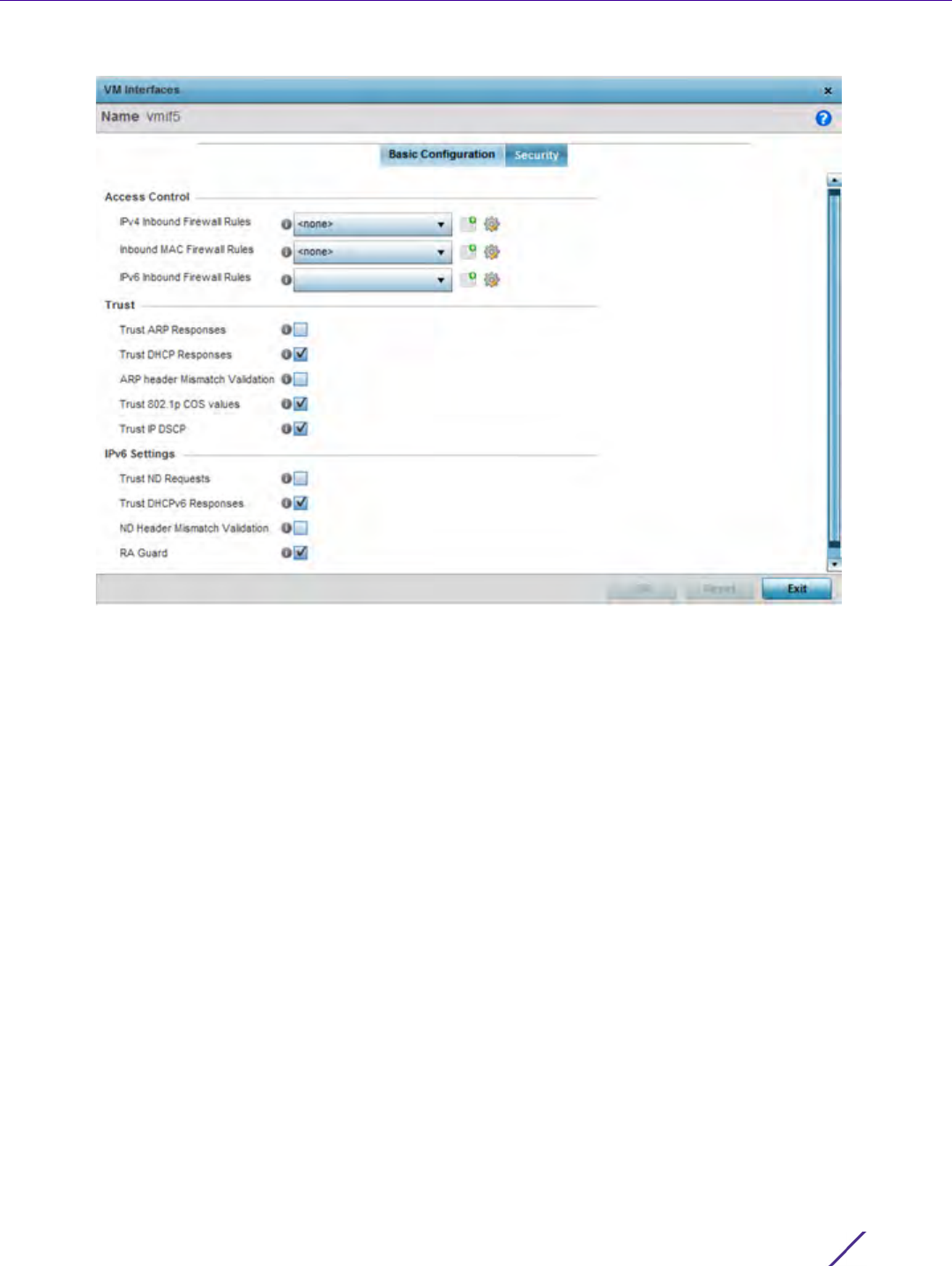
Device Configuration
Wireless Controller and Service Platform System Reference Guide 5 - 88
Figure 5-51 Profile Overrides - VM Interfaces Security screen
13 Refer to the Access Control field. As part of the VM interface’s security configuration, IPv4 and IPv6 Inbound
and MAC Inbound address firewall rules are required.
14 Use the drop-down menus to select the firewall rules to apply to this profile’s VM interface configuration. The
firewall inspects IP and MAC traffic flows and detects attacks typically not visible to traditional wired firewall
appliances.
15 Use the IPv4 Inbound Firewall Rules drop down menu to select the IPv4 specific firewall rules to apply to this
profile’s VM interface configuration. IPv4 is a connectionless protocol for packet switched networking. IPv4
operates as a best effort delivery method, as it does not guarantee delivery, and does not ensure proper
sequencing or duplicate delivery (unlike (TCP). IPv4 hosts can use link local addressing to provide local
connectivity.
16 Use the IPv6 Inbound Firewall Rules drop down menu to select the IPv6 specific firewall rules to apply to this
profile’s VM interface configuration. IPv6 is the latest revision of the Internet Protocol (IP) designed to replace
IPv4. IPV6 provides enhanced identification and location information for computers on networks routing traffic
across the Internet. IPv6 addresses are composed of eight groups of four hexadecimal digits separated by
colons.
17 If a firewall rule does not exist suiting the data protection needs of the target VM interface configuration, select
the Create icon to define a new rule configuration, or the Edit icon to modify an existing firewall rule
configuration.

Device Configuration
Wireless Controller and Service Platform System Reference Guide 5 - 89
18 Refer to the Trust section to define or override the following:
19 Set the following IPv6 Settings:
20 Select OK to save the changes and overrides to the security configuration. Select Reset to revert to the last
saved configuration.
5.2.7.5 Radio Override Configuration
Profile Interface Override Configuration
Access Points can have their radio profile configurations overridden once their radios have successfully associated
to the network.
To define a radio configuration override from the Access Point’s associated controller or service platform:
1Select
Devices from the Configuration tab.
The Device Configuration screen displays a list of managed devices or peer controllers, service platforms or
Access Points.
2 Select an Access Point (by double-clicking it) from amongst those displayed within the Device Configuration
screen.
Trust ARP Responses Select this option to enable ARP trust on this VM interface. ARP packets
received on this port are considered trusted, and information from these
packets is used to identify rogue devices. The default value is disabled.
Trust DHCP Responses Select this option to enable DHCP trust on this VM interface. If enabled,
only DHCP responses are trusted and forwarded on this VM interface,
and a DHCP server can be connected only to a DHCP trusted port. The
default value is enabled.
ARP header Mismatch
Validation
Select this option to enable a source MAC mismatch check in both the
ARP and Ethernet header. The default value is enabled.
Trust 802.1p COS
values
Select this option to enable 802.1p COS values on this VM interface. The
default value is enabled.
Trust IP DSCP Select this option to enable IP DSCP values on this VM interface. The
default value is disabled.
Trust ND Requests Select this option to enable the trust of neighbor discovery requests
required on an IPv6 network on this VM interface. This setting is
disabled by default.
Trust DHCPv6
Responses
Select this option to enable the trust all DHCPv6 responses on this VM
interface. DHCPv6 is a networking protocol for configuring IPv6 hosts
with IP addresses, IP prefixes or other configuration attributes required
on an IPv6 network. DHCPv6 relay agents receive messages from clients
and forward them a DHCPv6 server. The server sends responses back to
the relay agent, and the relay agent sends the responses to the client on
the local link. This setting is enabled by default.
ND Header Mismatch
Validation
Select this option to enable a mismatch check for the source MAC within
the ND header and link layer option. This setting is disabled by default.
RA Guard Select this option to enable router advertisements or ICMPv6 redirects
from this VM interface. Router advertisements are periodically sent to
hosts or sent in response to neighbor solicitation requests. The
advertisement includes IPv6 prefixes and other subnet and host
information. This setting is disabled by default.
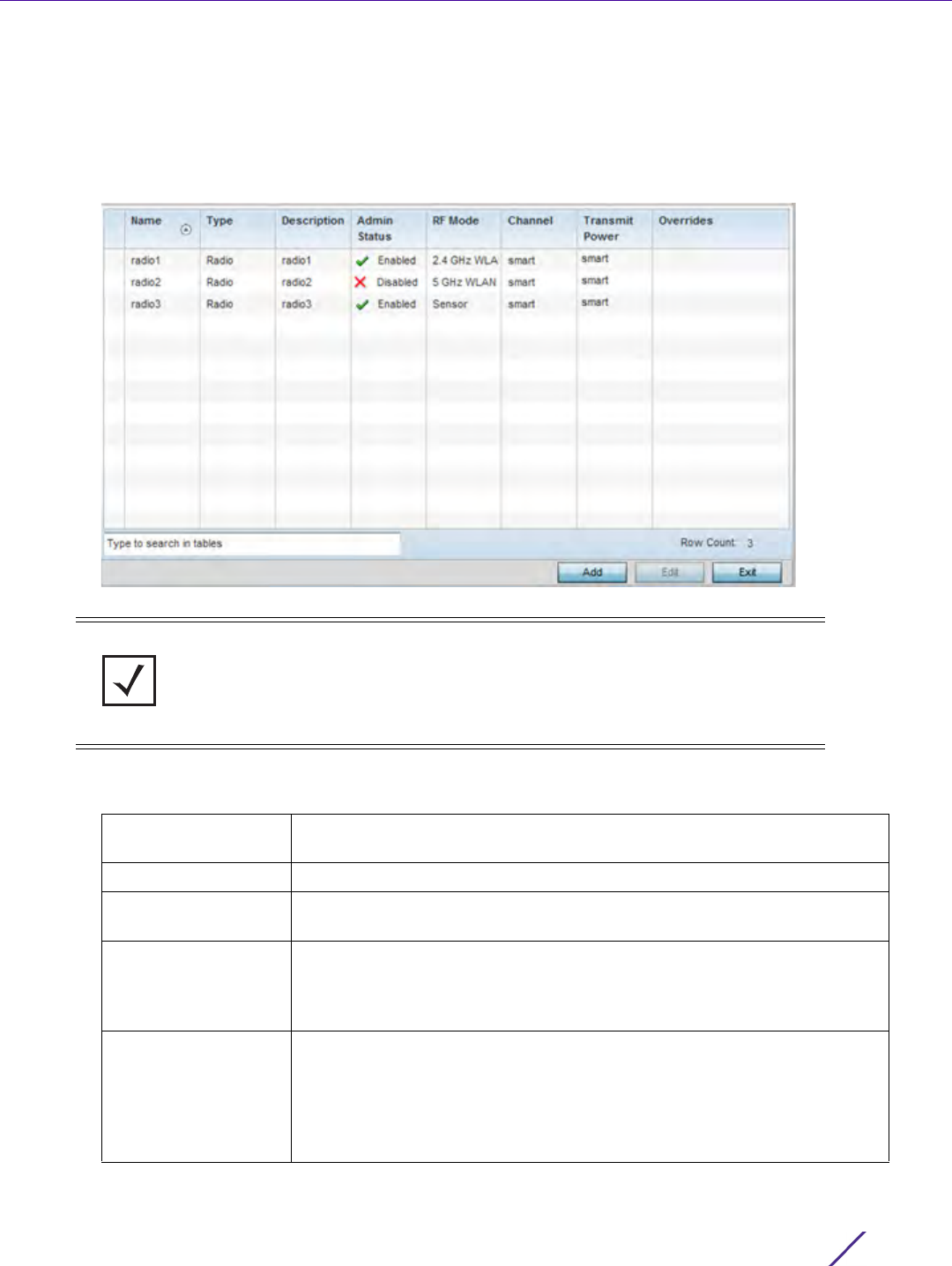
Device Configuration
Wireless Controller and Service Platform System Reference Guide 5 - 90
Devices can also be selected directly from the Device Browser in the lower, left-hand, side of the UI.
3Select
Profile Overrides from the Device menu to expand it into sub menu options.
4Select
Interface to expand its sub menu options.
5Select
Radios.
Figure 5-52 Profile Overrides - Radios screen
6 Review the following radio configuration data to determine whether a radio configuration requires modification
or override to better support the managed network:
NOTE: A blue override icon (to the left of a parameter) defines the parameter as
having an override applied. To remove an override go to the Basic Configuration
section of the device and click the Clear Overrides button. This removes all
overrides from the device.
Name Displays whether the reporting radio is the Access Point’s radio1, radio2 or
radio3.
Type Displays the type of radio housed by each listed Access Point.
Description Displays a brief description of the radio provided by the administrator
when the radio’s configuration was added or modified.
Admin Status A green check mark defines the listed radio configuration as active and
enabled with its supported profile. A red “X” defines the Virtual Interface
as currently disabled. The interface status can be modified when a new
Virtual Interface is created or an existing one modified.
RF Mode Displays whether each listed radio is operating in the 802.11an or
802.11bgn radio band. If the radio is a dedicated sensor, it will be listed as
a sensor to define the radio as not providing typical WLAN support. If the
radio is a client-bridge, it provides a typical bridging function and does
not provide WLAN support. The radio band is set from within the Radio
Settings tab.
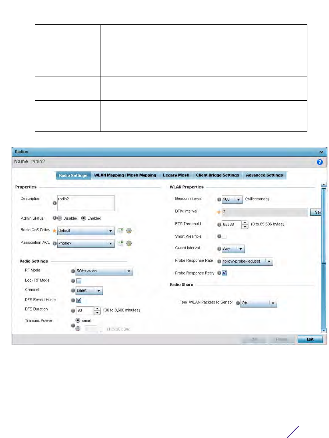
Device Configuration
Wireless Controller and Service Platform System Reference Guide 5 - 91
7 If required, select a radio configuration and select Edit to modify or override portions of its configuration.
Figure 5-53 Profile Overrides - Access Point Radio Settings tab
The Radio Settings tab displays by default.
Channel Lists the channel setting for the radio. Smart is the default setting. If set
to smart, the Access Point scans non-overlapping channels listening for
beacons from other Access Points. After the channels are scanned, it
selects the channel with the fewest Access Points. In the case of multiple
access points on the same channel, it will select the channel with the
lowest average power level. The column displays smart if set for dynamic
Smart RF support.
Transmit Power Lists the transmit power for each radio displayed as a value in milliwatts.
Selecting smart allows the radio to perform power adjustments to
compensate for failed neighboring radios
Overrides A Clear link appears for each radio configuration that has an override
applied to the profile’s configuration. Select Clear to revert this specific
radio configuration to the profile configuration originally defined by the
administrator for this radio.

Device Configuration
Wireless Controller and Service Platform System Reference Guide 5 - 92
8 Define or override the following radio configuration parameters from within the Properties field:
9 Set or override the following profile Radio Settings for the selected Access Point radio.
Description Provide or edit a description (1 - 64 characters in length) for the radio that
helps differentiate it from others with similar configurations.
Admin Status Either select the Enabled or Disabled radio button to define this radio’s
current status within the network. When enabled, the Access Point is
operational and available for client support within the network. The radio
is enabled by default and must be manually shutdown.
Radio QoS Policy Use the drop-down menu to specify an existing QoS policy to apply to the
Access Point radio in respect to its intended radio traffic. If there’s no
existing suiting the radio’s intended operation, select the Create icon to
define a new QoS policy that can be applied to this profile. For more
information, see Radio QoS Policy on page 6-66.
Association ACL Use the drop-down menu to specify an existing Association ACL policy to
apply to the Access Point radio. An Association ACL is a policy-based
Access Control List (ACL) that either prevents or allows wireless clients
from connecting to a managed Access Point radio. An ACL is a sequential
collection of permit and deny conditions that apply to controller or service
platform packets. When a packet is received on an interface, the controller
or service platform compares the fields in the packet against any applied
ACLs to verify the packet has the required permissions to be forwarded,
based on the criteria specified in the access lists. If a packet does not
meet any of the criteria specified in the ACL, the packet is dropped. Select
the Create icon to define a new Association ACL that can be applied to
this profile.
RF Mode Set the mode to either 2.4 GHz WLAN or 5 GHz WLAN depending on the
radio’s intended client support requirement. Set the mode to Sensor if
using the radio for rogue device detection. To set a radio as a detector,
disable sensor support on the other Access Point radio. Set the mode to
scan-ahead in DFS aware countries to allow a mesh points secondary
radio to scan for an alternative channel for backhaul transmission in the
event of a radar event on the principal radio. The secondary radio is
continually monitoring the alternate channel, which means the principal
radio can switch channels and transmit data immediately without waiting
for the channel availability check.
Lock RF Mode Select this option to lock Smart RF for this radio. The default setting is
disabled.
Channel Use the drop-down menu to select the channel of operation for the radio.
Only a trained installation professional should define the radio channel.
Select Smart for the radio to scan non-overlapping channels listening for
beacons from other Access Points. After channels are scanned, the radio
selects the channel with the fewest Access Points. In the case of multiple
Access Points on the same channel, it selects the channel with the lowest
average power level. The default value is Smart. Channels with a “w”
appended to them are unique to the 40 MHz band. Channels with a “ww”
appended to them are 802.11ac specific, only appear when using an
AP8232, and are unique to the 80 MHz band.
DFS Revert Home Select this option to revert to the home channel after a DFS evacuation
period.

Device Configuration
Wireless Controller and Service Platform System Reference Guide 5 - 93
DFS Duration Set the DFS duration between 30 to 3,600 minutes. This is the duration
for which the radio stays in the in the new channel. The default value is 90
minutes.
Transmit Power Set the transmit power of the selected Access Point radio. If using a dual
or three radio model Access Point, each radio should be configured with a
unique transmit power in respect to its intended client support function.
Select the Smart RF option to let Smart RF determine the transmit power.
A setting of 0 defines the radio as using Smart RF to determine its output
power. 20 dBm is the default value.
Antenna Gain Set the antenna between 0.00 - 15.00 dBm. The access point’s Power
Management Antenna Configuration File (PMACF) automatically
configures the access point’s radio transmit power based on the antenna
type, its antenna gain (provided here) and the deployed country’s
regulatory domain restrictions. Once provided, the access point calculates
the power range. Antenna gain relates the intensity of an antenna in a
given direction to the intensity that would be produced ideally by an
antenna that radiates equally in all directions (isotropically), and has no
losses. Although the gain of an antenna is directly related to its directivity,
its gain is a measure that takes into account the efficiency of the antenna
as well as its directional capabilities. Only a professional installer should
set the antenna gain. The default value is 0.00.
Antenna Mode Set the number of transmit and receive antennas on the Access Point. 1x1
is used for transmissions over just the single “A” antenna, 1x3 is used for
transmissions over the “A” antenna and all three antennas for receiving.
2x2 is used for transmissions and receipts over two antennas for dual
antenna models. The default setting is dynamic based on the Access Point
model deployed and its transmit power settings.
Enable Antenna
Diversity
Select this option to enable antenna diversity on supported antennas.
Antenna diversity uses two or more antennas to increase signal quality
and strength. This option is disabled by default.
Adaptivity Recovery Select this option to switch channels when an Access Point‘s radio is in
adaptivity mode. In adaptivity mode, an Access Point monitors
interference on its set channel and stops functioning when the radio’s
defined interference tolerance level is exceeded. When the defined
adaptivity timeout is exceeded, the radio resumes functionality on a
different channel. This option is enabled by default.
Adaptivity Timeout Set the adaptivity timeout from 30 to 3,600 minutes. The default setting
is 90 minutes.
Wireless Client
Power
Select this option to specify the transmit power on supported wireless
clients. If this is enabled set a client power level between 0 to 20 dBm.
This option is disabled by default.
Dynamic Chain
Selection
Select this option for the radio to dynamically change the number of
transmit chains. This option is enabled by default.

Device Configuration
Wireless Controller and Service Platform System Reference Guide 5 - 94
Rate Use the Select button to set rate options depending on the 802.11
protocols selected. If the radio band is set to Sensor or Detector, the Data
Rates drop-down menu is not enabled, as the rates are fixed and not user
configurable. If 2.4 GHz is selected as the radio band, select separate
802.11b, 802.11g and 802.11n rates and define how they are used in
combination. If 5 GHz is selected as the radio band, select separate 802.11a
and 802.11n rates then define how they are used together. When using
802.11n (in either the 2.4 or 5 GHz band), Set a MCS (modulation and
coding scheme) in respect to the radio’s channel width and guard interval.
A MCS defines (based on RF channel conditions) an optimal combination
of 8 data rates, bonded channels, multiple spatial streams, different guard
intervals and modulation types. Clients can associate as long as they
support basic MCS (as well as non-11n basic rates).
If dedicating an AP81XX model radio to either 2.4 or 5 Ghz support, a
Custom Rates option is available to set a modulation and coding scheme
(MCS) in respect to the radio’s channel width and guard interval. A MCS
defines (based on RF channel conditions) an optimal combination of rates,
bonded channels, multiple spatial streams, different guard intervals and
modulation types. Clients can associate as long as they support basic MCS
(as well as non-11n basic rates). If Basic is selected within the 802.11n Rates
field, the MCS0-7 option is auto selected as a Supported rate and that
option is greyed out. If Basic is not selected, any combination of MCS0-7,
MCS8-15 and MCS16-23 can be supported, including a case where MCS0-7
and MCS16-23 are selected and not MCS8-15. The MCS0-7 and MCS8-15
options are available to each support Access Point. However, the MCS16-
23 option is only available to AP81XX model Access Points and its ability
to provide 3x3x3 MIMO support.
Radio Placement Use the drop-down menu to specify whether the radio is located Indoors
or Outdoors. The placement should depend on the country of operation
selected and its regulatory domain requirements for radio emissions. The
default setting is Indoors.
Max Clients Use the spinner control to set a maximum permissible number of clients
to connect with this radio. The available range is from 0 - 256 clients. The
default is 256.
Rate Selection
Methods
Specify a radio selection method for the radio. The selection methods are:
Standard - standard monotonic radio selection method will be used.
Opportunistic - sets opportunistic radio link adaptation (ORLA) as the
radio selection method. This mode uses opportunistic data rate selection
to provide the best throughput. The ORLA rate selection mode is
supported only on the AP7161 and AP8163 model Access Points.

Device Configuration
Wireless Controller and Service Platform System Reference Guide 5 - 95
10 Set or override the following profile WLAN Properties for the selected Access Point radio:
Beacon Interval Set the interval between radio beacons in milliseconds (either 50, 100 or
200). A beacon is a packet broadcast by adopted radios to keep the
network synchronized. Included in a beacon is the WLAN service area,
radio address, broadcast destination addresses, a time stamp, and
indicators about traffic and delivery (such as a DTIM). Increase the DTIM/
beacon settings (lengthening the time) to let nodes sleep longer and
preserve battery life. Decrease these settings (shortening the time) to
support streaming-multicast audio and video applications that are jitter-
sensitive. The default value is 100 milliseconds.
DTIM Interval Set a DTIM Interval to specify a period for Delivery Traffic Indication
Messages (DTIM). A DTIM is periodically included in a beacon frame
transmitted from adopted radios. The DTIM indicates broadcast and
multicast frames (buffered at the Access Point) are soon to arrive. These
are simple data frames that require no acknowledgment, so nodes
sometimes miss them. Increase the DTIM/ beacon settings (lengthening
the time) to let nodes sleep longer and preserve their battery life.
Decrease these settings (shortening the time) to support streaming
multicast audio and video applications that are jitter-sensitive.
RTS Threshold Specify a Request To Send (RTS) threshold (between 1 - 65,636 bytes) for
use by the WLAN's adopted Access Point radios. RTS is a transmitting
station's signal that requests a Clear To Send (CTS) response from a
receiving client. This RTS/CTS procedure clears the air where clients are
contending for transmission time. Benefits include fewer data collisions
and better communication with nodes that are hard to find (or hidden)
because of other active nodes in the transmission path.
Control RTS/CTS by setting an RTS threshold. This setting initiates an
RTS/CTS exchange for data frames larger than the threshold, and sends
(without RTS/CTS) any data frames smaller than the threshold.
Consider the trade-offs when setting an appropriate RTS threshold for the
WLAN's Access Point radios. A lower RTS threshold causes more frequent
RTS/CTS exchanges. This consumes more bandwidth because of
additional latency (RTS/CTS exchanges) before transmissions can
commence. A disadvantage is the reduction in data-frame throughput. An
advantage is quicker system recovery from electromagnetic interference
and data collisions. Environments with more wireless traffic and
contention for transmission make the best use of a lower RTS threshold.
A higher RTS threshold minimizes RTS/CTS exchanges, consuming less
bandwidth for data transmissions. A disadvantage is less help to nodes
that encounter interference and collisions. An advantage is faster data-
frame throughput. Environments with less wireless traffic and contention
for transmission make the best use of a higher RTS threshold.
Short Preamble If using an 802.11bg radio, select this option to transmit using a short
preamble. Short preambles improve throughput. However, some devices
(SpectraLink/Polycomm phones) require long preambles. The default
value is disabled.
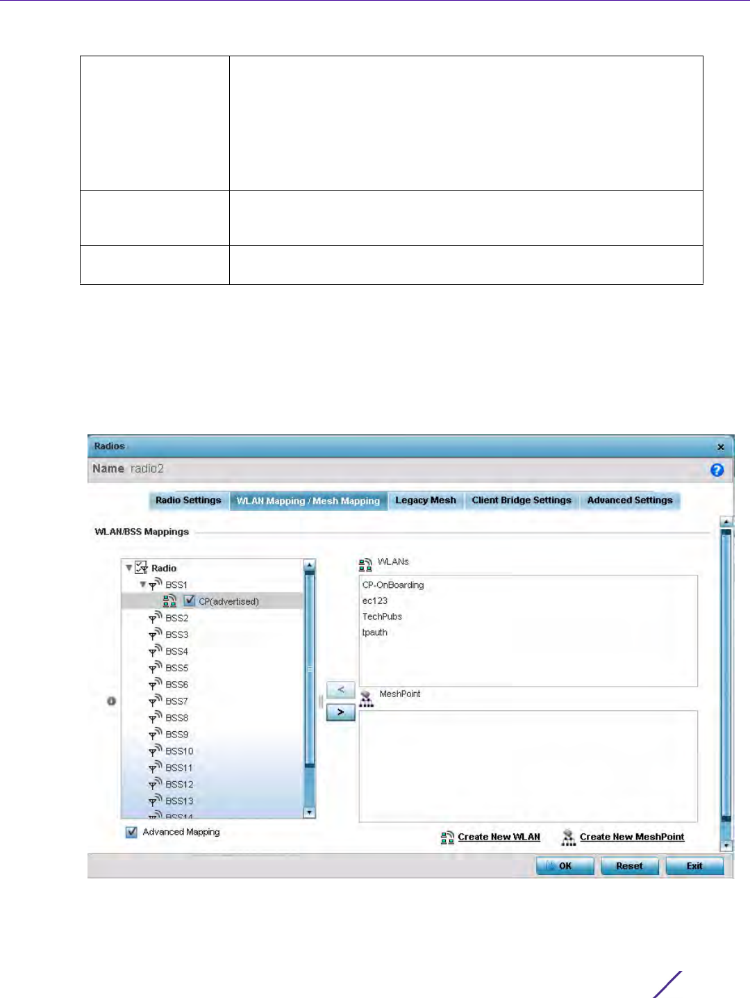
Device Configuration
Wireless Controller and Service Platform System Reference Guide 5 - 96
11 Select a mode from the Feed WLAN Packets to Sensor check box in the Radio Share section to enable this
feature. Select either Inline or Promiscuous mode to allow the packets the radio is switching to also be used by
the WIPS analysis module. This feature can be enabled in two modes: an inline mode where the WIPS sensor
receives the packets from the radios with radio operating in normal mode. A promiscuous mode where the
radio is configured to a mode where it receives all packets on the channel whether the destination address is
the radio or not, and the WIPS module can analyze them.
12 Select the WLAN Mapping/Mesh Mapping tab.
Figure 5-54 Profile Overrides - Access Point Radio WLAN Mapping tab
13 Refer to the WLAN/BSS Mappings field to set or override WLAN BSSID assignments for an existing Access
Point deployment.
Guard Interval Use the drop-down menu to specify a Long or Any guard interval. The
guard interval is the space between characters being transmitted. The
guard interval eliminates inter-symbol interference (ISI). ISI occurs when
echoes or reflections from one character interfere with another character.
Adding time between transmissions allows echo's and reflections to settle
before the next character is transmitted. A shorter guard interval results in
shorter character times which reduces overhead and increases data rates
by up to 10%. The default value is Long.
Probe Response Rate Use the drop-down menu to specify the data rate used for the
transmission of probe responses. Options include, highest-basic, lowest-
basic and follow-probe-request (default setting).
Probe Response
Retry
Select this option to retry probe responses if they are not acknowledged
by the target wireless client. The default value is enabled.
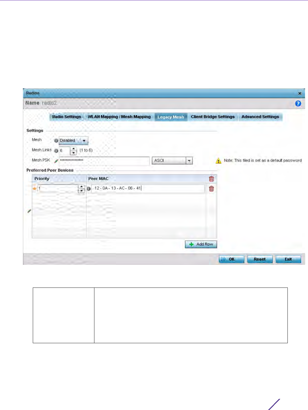
Device Configuration
Wireless Controller and Service Platform System Reference Guide 5 - 97
Administrators can assign each WLAN its own BSSID. If using a single-radio access point, there are 8 BSSIDs
available. If using a dual-radio access point there are 8 BSSIDs for the 802.11b/g/n radio and 8 BSSIDs for the
802.11a/n radio.
14 Select Advanced Mapping to enable WLAN mapping to a specific BSS ID.
15 Select OK to save the changes and overrides to the WLAN Mapping. Select Reset to revert to the last saved
configuration.
16 Select the Legacy Mesh tab.
Figure 5-55 Profile Overrides - Access Point Legacy Mesh tab
17 Refer to the Settings field to define or override basic mesh settings for the Access Point radio.
Mesh Use the drop-down to set the mesh mode for this radio. Available options
include Disabled, Portal or Client. Setting the mesh mode to Disabled
deactivates all mesh activity on this radio. Setting the mesh mode to
Portal turns the radio into a mesh portal. This will start the radio
beaconing immediately and will accept connections from other mesh
nodes. Setting the mesh mode to client enables the radio to operate as a
mesh client that scans and connects to mesh portals or nodes connected
to portals.
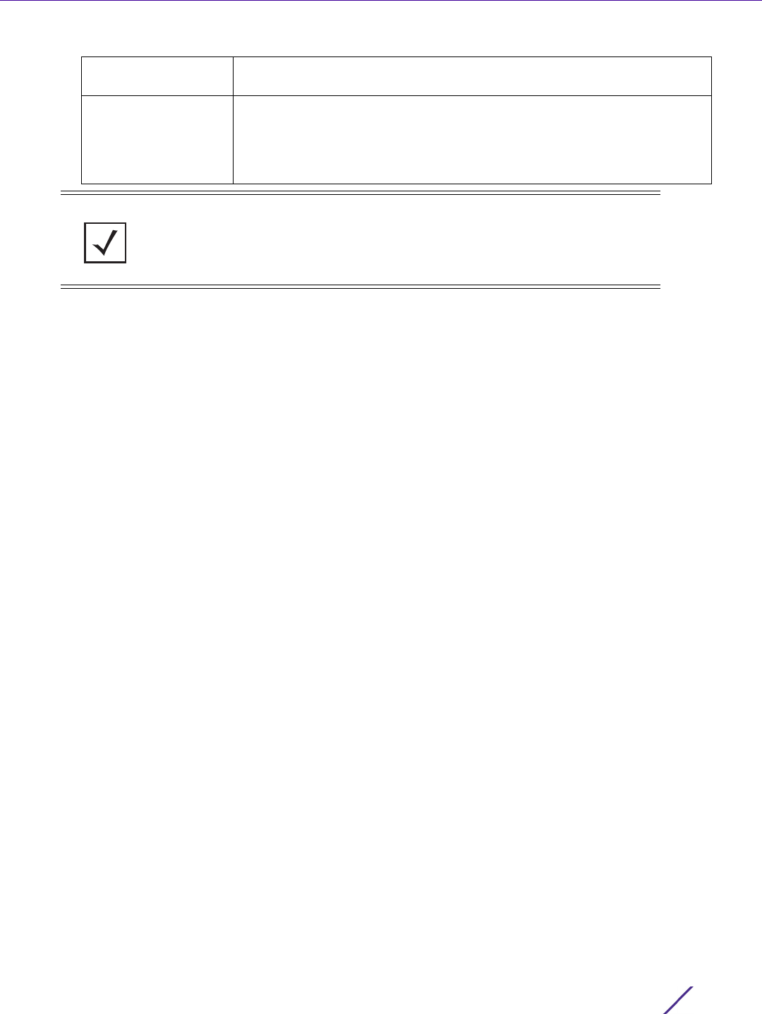
Device Configuration
Wireless Controller and Service Platform System Reference Guide 5 - 98
18 Refer to the Preferred Peer Devices table to add mesh peers. For each peer being added enter its MAC Address
and a Priority from 1 - 6. The lower the priority number assigned, the higher the priority it’s given when
connecting to the mesh infrastructure.
19 Select the + Add Row button to add preferred peer devices for the radio to connect to in mesh mode.
20 Select the Client Bridge Settings tab to configure the selected radio as a client-bridge. Note, before configuring
the client-bridge parameters, set the radio's rf-mode to bridge.
An Access Point's radio can be configured to form a bridge between its wireless/wired clients and an
infrastructure WLAN. The bridge radio authenticates and associates with an infrastructure WLAN Access Point.
After successful association, the Access Point switches frames between its bridge radio and wired/wireless
client(s) connected either to its GE port(s) or to the other radio, there by providing the clients access to the
infrastructure WLAN resources. This feature is supported only on the AP6522, AP6562, AP7602, AP7532,
AP7562, AP7602, and AP7622 model Access Points.
Mesh Links Specify the number of mesh links allowed by the radio. The radio can
have from 1- 6 mesh links when the radio is configured as a Portal.
Mesh PSK Provide the encryption key in either ASCII or Hex format. Administrators
must ensure this key is configured on the Access Point when staged for
mesh, added to the mesh client and to the portal Access Point’s
configuration on the controller or service platform. Select Show to expose
the characters used in the PSK.
NOTE: Only single hop mesh links are supported at this time.
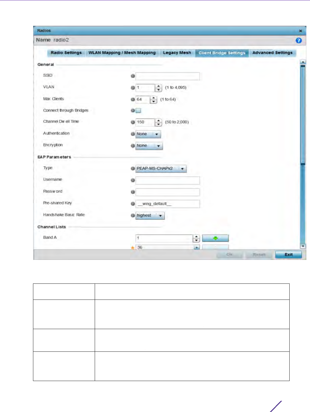
Device Configuration
Wireless Controller and Service Platform System Reference Guide 5 - 99
Figure 5-56 Profile - Access Point Client Bridge Settings tab
21 Refer to the General field and define the following configurations:
SSID Set the infrastructure WLAN’s SSID the client-bridge Access Point
associates with.
VLAN Set the VLAN to which the bridged clients’ sessions are mapped after
successful association with the infrastructure WLAN. Once mapped, the
client bridge communicates with permitted hosts over the infrastructure
WLAN. Specify the VLAN from 1 to 4095.
Max Clients Set the maximum number of client-bridge Access Points that can
associate with the infrastructure WLAN. Specify a value from 1 to 64. The
default value is 64.
Connect through
Bridges
Select this option to enable the client-bridge access point radio to
associate with the infrastructure WLAN through another client-bridge
radio thereby forming a chain. This is referred to as daisy chaining of
client-bridge radios. This option is disabled by default.

Device Configuration
Wireless Controller and Service Platform System Reference Guide 5 - 100
22 Refer to the EAP Parameters field and define the following EAP authentication parameters:
23 Refer to the Channel Lists field and define the list of channels the client-bridge radio scans when scanning for
an infrastructure WLAN.
24 Refer to the Keepalive Parameters field and define the following configurations:
Channel Dwell Time Set the channel-dwell time from 50 to 2000 milliseconds. This is the time
the client-bridge radio dwells on each channel (configured in the list of
channels) when scanning for an infrastructure WLAN. The default is 150
milliseconds.
Authentication Set the mode of authentication with the infrastructure WLAN. The
authentication mode specified here should be the same as that
configured on the infrastructure WLAN. The options are None and EAP. If
selecting EAP, specify the EAP authentication parameters. The default
setting in None.
For information on WLAN authentication, see Configuring WLAN
Security.
Encryption Set the packet encryption mode. The encryption mode specified here
should be the same as that configured on the infrastructure WLAN. The
options are None, CCMP and TKIP. The default setting is None.
For information on WLAN encryption, see Configuring WLAN Security.
Type Use the drop-down menu to select the EAP authentication method used
by the supplicant. The options are TLS and PEAP-MS-CHAPv2. The
default EAP type is PEAP-MS-CHAPv2.
Username Set the 32 character maximum user name for an EAP authentication
credential exchange.
Password Set the 32 character maximum password for the EAP user name specified
above.
Pre-shared Key Set the pre-shared key (PSK) used with EAP. Note, the authenticating
algorithm and PSK configured should be same as that on the
infrastructure WLAN.
Handshake Basic
Rate
Set the basic rate of exchange of handshake packets between the client-
bridge and infrastructure WLAN Access Points. The options are highest
and normal. The default value is highest.
Band A Define a list of channels for scanning across all the channels in the 5.0
GHz radio band.
Band BG Define a list of channels for scanning across all the channels in the 2.4
GHz radio band.
Keepalive Type Set the keepalive frame type exchanged between the client-bridge and
infrastructure Access Points. This is the type of packets exchanged
between the client-bridge and infrastructure Access Points, at specified
intervals, to keep the client-bridge link up and active. The options are null-
data and WNMP packets. The default value is null-data.

Device Configuration
Wireless Controller and Service Platform System Reference Guide 5 - 101
25 Refer to the Radio Link Behaviour field and define the following configurations:
26 Refer to the Roam Criteria field and define the following configuration:
27 Select OK to save or override the changes to the Client Bridge Settings screen. Select Reset to revert to the last
saved configuration.
28 Select the Advanced Settings tab.
Keepalive Interval Set the keepalive interval from 0 - 86,400 seconds. This is the interval
between two successive keepalive frames exchanged between the client-
bridge and infrastructure Access Points. The default value is 300 seconds.
Inactivity Timeout Set the inactivity timeout for each bridge MAC address from 0 - 8,64,000
seconds. This is the time for which the client-bridge access point waits
before deleting a wired/wireless client’s MAC address from which a frame
has not been received for more than the time specified here. For example,
if the inactivity time is set at 120 seconds, and if no frames are received
from a client (MAC address) for 120 seconds, it is deleted. The default
value is 600 seconds.
Shutdown Other
Radio when Link
Goes Down
Select this option to enable shutting down of the non-client bridge radio
(this is the radio to which wireless-clients associate) when the link
between the client-bridge and infrastructure access points is lost. When
enabled, wireless clients associated with the non-client bridge radio are
pushed to search for and associate with other access points having
backhaul connectivity. This option is disabled by default.
If enabling this option, specify the time for which the non-client bridge
radio is shut down. Use the spinner to specify a time from 1 - 1,800
seconds.
Refresh VLAN
Interface when Link
Comes Up
Select this option to enable the SVI to refresh on re-establishing client
bridge link to the infrastructure Access Point. And, if using a DHCP
assigned IP address, it also causes a DHCP renew. This option is enabled
by default.
Seconds for Missed
Beacons
Set this interval from 0 to 60 seconds. This is the time for which the
client-bridge Access Point waits, after missing a beacon from the
associated infrastructure WLAN Access Point, before roaming to another
infrastructure Access Point. For example, if the Seconds for Missed
Beacon is set to 30 seconds, and if more than 30 seconds have passed
since the last beacon received from the infrastructure Access Point, the
client-bridge Access Point resumes scanning for another infrastructure
Access Point. The default value s 20 seconds.
Minimum Signal
Strength
Set the minimum signal-strength threshold for signals received from the
infrastructure Access Point. Specify a value from -128 to -40 dBm. If the
RSSI value of signals received from the infrastructure access point falls
below the value specified here, the client-bridge access point resumes
scanning for another infrastructure access point. The default is -75 dBm.
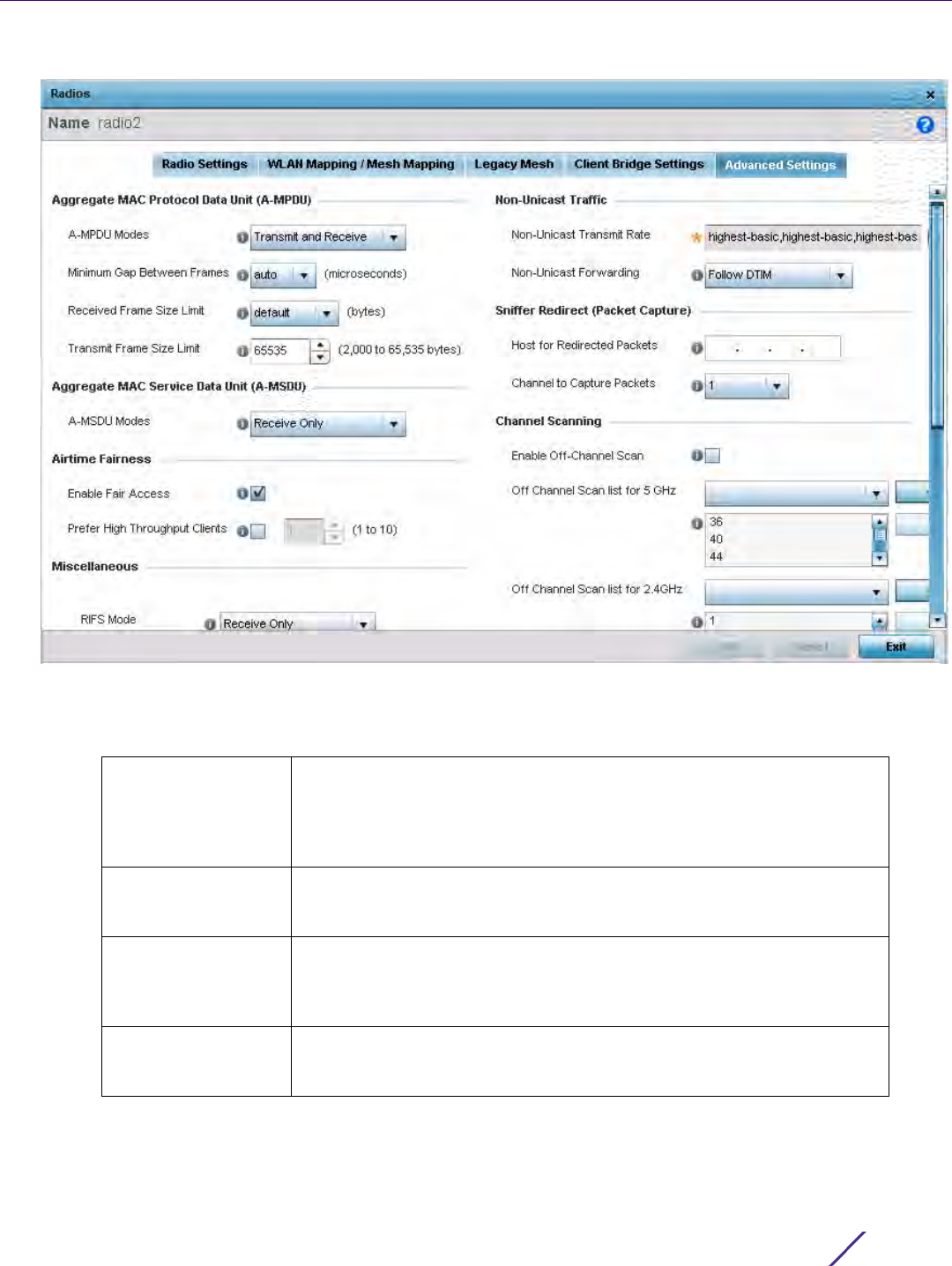
Device Configuration
Wireless Controller and Service Platform System Reference Guide 5 - 102
Figure 5-57 Profile Overrides - Access Point Radio Advanced Settings tab
29 Refer to the Aggregate MAC Protocol Data Unit (A-MPDU) field to define or override how MAC service frames
are aggregated by the Access Point radio.
30 Use the A-MSDU Modes drop-down menu in the Aggregate MAC Service Data Unit (A-MSDU) section to set or
override the supported A-MSDU mode.
Available modes include Receive Only and Transmit and Receive. Transmit and Receive is the default value.
Using Transmit and Receive, frames up to 4 KB can be sent and received. The buffer limit is not configurable.
A-MPDU Modes Use the drop-down menu to define the A-MPDU mode supported.
Options include Transmit Only, Receive Only, Transmit and Receive and
None. The default value is Transmit and Receive. Using the default value,
long frames can be both sent and received (up to 64 KB). When enabled,
define either a transmit or receive limit (or both).
Minimum Gap
Between Frames
Use the drop-down menu to define the minimum gap between A-MPDU
frames (in microseconds). The default value is 4 microseconds. A value of
auto designates the gap is set by the system.
Received Frame Size
Limit
If a support mode is enabled allowing A-MPDU frames to be received,
define an advertised maximum limit for received A-MPDU aggregated
frames. Options include 8191, 16383, 32767 or 65535 bytes. The default
value is 65535 bytes.
Transmit Frame Size
Limit
Use the spinner control to set a limit on transmitted A-MPDU aggregated
frames. The available range is from 2,000 - 65,535 bytes. The default
value is 65535 bytes.

Device Configuration
Wireless Controller and Service Platform System Reference Guide 5 - 103
31 Use the Airtime Fairness fields to optionally prioritize wireless access to devices.
Select Enable Fair Access to enable this feature and provide equal access client access to radio resources.
Select Prefer High Throughput Clients to prioritize clients with higher throughput (802.11n clients) over clients
with slower throughput (802.11 a/b/g) clients. Use the spinner control to set a weight for the higher throughput
clients.
32 Set or override the following Miscellaneous advanced radio settings:
33 Set or override the following Aeroscout Properties:
RIFS Mode Define a RIFS mode to determine whether interframe spacing is applied
to Access Point transmissions or received packets, both, or neither The
default mode is Transmit and Receive. Interframe spacing is an interval
between two consecutive Ethernet frames to enable a brief recovery
between packets and allow target devices to prepare for the reception of
the next packet. Consider setting this value to None for high priority
traffic to reduce packet delay.
STBC Mode Select a space–time block coding (STBC) option to transmit multiple data
stream copies across Access Point antennas to improve signal reliability.
An Access Point’s transmitted signal traverses a problematic environment,
with scattering, reflection and refraction all prevalent. The signal can be
further corrupted by noise at the receiver. Consequently, some of the
received data copies are less corrupt and better than others. This
redundancy means there’s a greater chance of using one, or more, of the
received copies to successfully decode the signal. STBC effectively
combines all the signal copies to extract as much information from each
as possible.
Transmit
Beamforming
Enable beamforming to steer signals to peers in a specific direction to
enhance signal strength and improve throughput amongst meshed
devices (not clients). Each Access Point radio support up to 16
beamforming capable mesh peers. When enabled, a beamformer steers
its wireless signals to its peers. A beamformee device assists the
beamformer with channel estimation by providing a feedback matrix. The
feedback matrix is a set of values sent by the beamformee to assist the
beamformer in computing a steering matrix. A steering matrix is an
additional set of values used to steer wireless signals at the beamformer
so constructive signals arrive at the beamformee for better SNR and
throughput. Any beamforming capable mesh peer connecting to a radio
whose capacity is exhausted cannot enable beamforming itself. Transmit
beamforming is available on AP81XX (AP8122, AP8132 and AP8163) model
Access Points only, and is disabled by default.
Forwarding Host Specify the Aeroscout engine’s IP address. When specified, the AP
forwards Aeroscout beacons directly to the Aeroscout locationing engine
without proxying through the controller or RF Domain manager.
Note: Aeroscout beacon forwarding is supported only on the AP6532, AP7502,
AP7522, AP7532, AP7562, AP8432, AP8533 model Access Points.
Forwarding Port Use the spinner control to set the port on which the Aeroscout engine is
reachable.
MAC to be forwarded Specify the MAC address to be forwarded.

Device Configuration
Wireless Controller and Service Platform System Reference Guide 5 - 104
34 Set or override the following Ekahau Properties:
35 Set or override the following Non-Unicast Traffic values for the profile’s supported Access Point radio and its
connected wireless clients:
36 Refer to the Sniffer Redirect (Packet Capture) field to define or override the radio’s captured packet
configuration.
37 Refer to the Channel Scanning field to define or override the radio’s captured packet configuration.
Forward Host Specify the Ekahau engine IP address. Using Ekahau small, battery
powered Wi-Fi tags are attached to tracked assets or carried by people.
Ekahau processes locations, rules, messages and environmental data and
turns the information into locationing maps, alerts and reports.
Forwarding Port Use the spinner control to set the Ekahau TZSP port used for processing
information from locationing tags.
MAC to be forwarded Specify the MAC address to be forwarded with location data requests.
Non-Unicast Transmit
Rate
Use the Select drop-down menu to launch a sub screen to define the data
rate for broadcast and multicast frame transmissions. Seven different
rates are available if the not using the same rate for each BSSID, each
with a separate menu.
Non-Unicast
Forwarding
Define whether client broadcast and multicast packets should always
follow DTIM, or only follow DTIM when using Power Save Aware mode.
The default setting is Follow DTIM.
Host for Redirected
Packets
If packets are re-directed from a controller or service platform’s
connected Access Point radio, define an IP address of a resource
(additional host system) used to capture the re- directed packets. This
address is the numerical (non DNS) address of the host used to capture
the re-directed packets.
Channel to Capture
Packets
Use the drop-down menu to specify the channel used to capture re-
directed packets. The default value is channel 1.
Enable Off-Channel
Scan
Enable this option to scan across all channels using this radio. Channel
scans use Access Point resources and can be time consuming, so only
enable when your sure the radio can afford the bandwidth be directed
towards to the channel scan and does not negatively impact client
support.
Off Channel Scan list
for 5GHz
Define a list of channels for off channel scans using the 5GHz Access
Point radio. Restricting off channel scans to specific channels frees
bandwidth otherwise utilized for scanning across all the channels in the
5GHz radio band.
Off Channel Scan list
for 2.4GHz
Define a list of channels for off channel scans using the 2.4GHz Access
Point radio. Restricting off channel scans to specific channels frees
bandwidth otherwise utilized for scanning across all the channels in the
2.4GHz radio band.
Max Multicast Set the maximum number (from 0 - 100) of multicast/broadcast
messages used to perform off channel scanning. The default setting is
four.

Device Configuration
Wireless Controller and Service Platform System Reference Guide 5 - 105
38 If an AP7161 or AP7181 is deployed, refer to the following AP7161/AP7181 specific values to set outdoor antenna
characteristics:
39 Select OK to save or override the changes to the Advanced Settings screen. Select Reset to revert to the last
saved configuration.
5.2.7.6 WAN Backhaul Override Configuration
Profile Interface Override Configuration
A Wireless Wide Area Network (WWAN) card is a specialized network interface card that allows a device to
connect, transmit and receive data over a Cellular Wide Area Network. The RFS4000 and RFS6000 each have a
PCI Express card slot that supports 3G WWAN cards. The WWAN card uses point to point protocol (PPP) to
connect to the Internet Service Provider (ISP) and gain access to the Internet. PPP is the protocol used for
establishing internet links over dial-up modems, DSL connections, and many other types of point-to-point
communications. PPP packages your system’s TCP/IP packets and forwards them to the serial device where they
can be put on the network. PPP is a full-duplex protocol that can be used on various physical media, including
twisted pair or fiber optic lines or satellite transmission. It uses a variation of High Speed Data Link Control (HDLC)
for packet encapsulation.
To define a WAN Backhaul configuration override:
1Select
Devices from the Configuration tab.
The Device Configuration screen displays a list of managed devices or peer controllers, service platforms or
Access Points.
2 Select a target Access Point (by double-clicking it) from amongst those displayed within the Device
Configuration screen.
Devices can also be selected directly from the Device Browser in the lower, left-hand, side of the UI.
3Select
Profile Overrides from the Device menu to expand it into sub menu options.
4Select
Interface to expand its sub menu options.
5Select
WAN Backhaul.
Scan Interval Set the interval (from 2 - 100 dtims) off channel scans occur. The default
setting is 20dtims.
Sniffer Redirect Specify the IP address of the host to which captured off channel scan
packets are redirected.
Enable Antenna
Downlift
Enable this settings (on AP7181 models only) to allow the Access Point to
physically transmit in a downward orientation (ADEPT mode).
Extended Range Set an extended range (from 1 - 25 kilometers) to allow AP7161 and
AP7181 model Access Points to transmit and receive with their clients at
greater distances without being timed out.
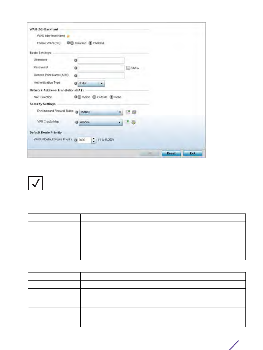
Device Configuration
Wireless Controller and Service Platform System Reference Guide 5 - 106
Figure 5-58 Profile Overrides -WAN Backhaul screen
6 Refer to the WAN (3G) Backhaul configuration to specify WAN card settings:
7 Define or override the following authentication parameters from within the Basic Settings field:
NOTE: A blue override icon (to the left of a parameter) defines the parameter as
having an override applied. To remove an override go to the Basic Configuration
section of the device and click the Clear Overrides button. This removes all
overrides from the device.
WAN Interface Name Displays the WAN Interface name for the WAN 3G Backhaul card.
Reset WAN Card If the WAN Card becomes unresponsive or is experiencing other errors
click the Reset WAN Card button to power cycle and reboot the WAN
card.
Enable WAN (3G) Check this box to enable 3G WAN card support on the device. A
supported 3G card must be connected to the device for this feature to
work properly.
Username Provide a username for authentication support by the cellular data carrier.
Password Provide a password for authentication support by the cellular data carrier.
Access Point Name
(APN)
Enter the name of the cellular data provider if necessary. This setting is
needed in areas with multiple cellular data providers using the same
protocols, such as Europe and Asia.
Authentication Type Use the drop-down menu to specify the authentication type used by the
cellular data provider. Supported authentication types are None, PAP,
CHAP, MSCHAP, and MSCHAP-v2.

Device Configuration
Wireless Controller and Service Platform System Reference Guide 5 - 107
8 Define or override the following NAT parameters from within the Network Address Translation (NAT) field:
9 Define or override the following security parameters from within the Security Settings field:
Define or override the following route parameters from within the Default Route Priority field:
10 Select OK to save or override the changes to the Advanced Settings screen. Select Reset to revert to the last
saved configuration.
5.2.7.7 PPPoE Override Configuration
Profile Interface Override Configuration
PPP over Ethernet (PPPoE) is a data-link protocol for dialup connections. PPPoE allows the access point to use a
broadband modem (DSL, cable modem, etc.) for access to high-speed data and broadband networks. Most DSL
providers support (or deploy) the PPPoE protocol. PPPoE uses standard encryption, authentication, and
compression methods as specified by the PPPoE protocol. PPPoE enables controllers, service platforms and Access
Points to establish a point-to-point connection to an ISP over existing Ethernet interface.
To provide this point-to-point connection, each PPPoE session learns the Ethernet address of a remote PPPoE
client, and establishes a session. PPPoE uses both a discover and session phase to identify a client and establish a
point-to-point connection. By using such a connection, a Wireless WAN fail over is available to maintain seamless
network access if the access point’s Wired WAN were to fail.
NAT Direction Define the Network Address Translation (NAT) direction. Options include:
Inside - The inside network is transmitting data over the network its
intended destination. On the way out, the source IP address is changed in
the header and replaced by the (public) IP address.
Outside - Packets passing through the NAT on the way back to the
controller or service platform managed LAN are searched against to the
records kept by the NAT engine. There, the destination IP address is
changed back to the specific internal private class IP address in order to
reach the LAN over the network.
None - No NAT activity takes place. This is the default setting.
IPv4 Inbound
Firewall Rules
Use the drop-down menu to select an inbound IPv4 ACL to associate with
traffic on the WAN backhaul. This setting pertains to IPv4 inbound traffic
only and not IPv6. IPv4 operates as a best effort delivery method, as it
does not guarantee delivery, and does not ensure proper sequencing or
duplicate delivery (unlike (TCP). IPv4 hosts can use link local addressing
to provide local connectivity. If an appropriate IP ACL does not exist,
select the Add button to create a new one.
VPN Crypto Map If necessary, specify a crypto map for the wireless WAN. A crypto map
can be up to 256 characters long. If a suitable crypto map is not available,
click the Create button to configure a new one.
WWAN Default Route
Priority
Use the spinner control to define a priority from 1 - 8,000 for the default
route learned by the wireless WAN. The default value is 3000.
NOTE: Devices with PPPoE enabled continue to support VPN, NAT, PBR and 3G fail
over on the PPPoE interface. Multiple PPPoE sessions are supported using a single
user account user account if RADIUS is configured to allow simultaneous access.

Device Configuration
Wireless Controller and Service Platform System Reference Guide 5 - 108
When PPPoE client operation is enabled, it discovers an available server and establishes a PPPoE link for traffic
slow. When a wired WAN connection failure is detected, traffic flows through the WWAN interface in fail-over
mode (if the WWAN network is configured and available). When the PPPoE link becomes accessible again, traffic
is redirected back through the access point’s wired WAN link.
When the access point initiates a PPPoE session, it first performs a discovery to identify the Ethernet MAC address
of the PPPoE client and establish a PPPoE session ID. In discovery, the PPPoE client discovers a server to host the
PPPoE connection.
To create a PPPoE point-to-point configuration:
1Select
Devices from the Configuration tab.
The Device Configuration screen displays a list of managed devices or peer controllers, service platforms or
Access Points.
2 Select a target Access Point (by double-clicking it) from amongst those displayed within the Device
Configuration screen.
Devices can also be selected directly from the Device Browser in the lower, left-hand, side of the UI.
3Select
Profile Overrides from the Device menu to expand it into sub menu options.
4Select
Interface to expand its sub menu options.
5Select
PPPoE.
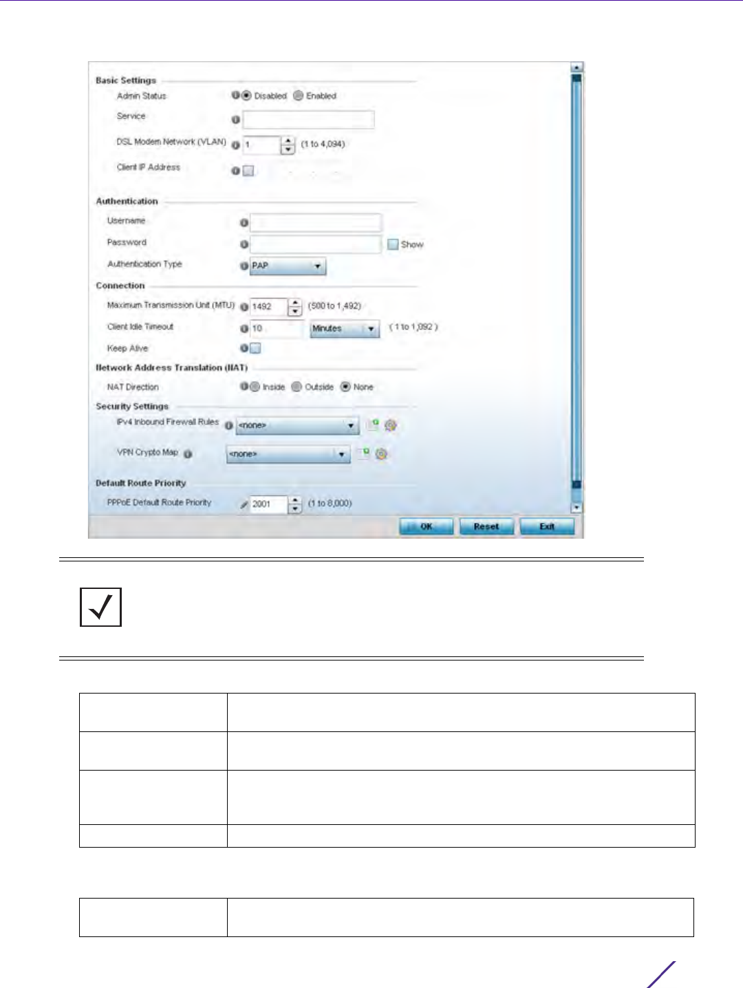
Device Configuration
Wireless Controller and Service Platform System Reference Guide 5 - 109
Figure 5-59 Profile Overrides -PPPoE screen
6Use the Basic Settings field to enable PPPoE and define a PPPoE client
7 Define the following Authentication parameters for PPPoE client interoperation:
NOTE: A blue override icon (to the left of a parameter) defines the parameter as
having an override applied. To remove an override go to the Basic Configuration
section of the device and click the Clear Overrides button. This removes all
overrides from the device.
Admin Status Select Enable to support a high speed client mode point-to-point
connection using the PPPoE protocol. The default setting is disabled.
Service Enter the 128 character maximum PPPoE client service name provided by
the service provider.
DSL Modem Network
(VLAN)
Use the spinner control to set the PPPoE VLAN (client local network)
connected to the DSL modem. This is the local network connected to DSL
modem. The available range is 1 - 4,094. The default VLAN is VLAN1.
Client IP Address Provide the numerical (non hostname) IP address of the PPPoE client.
Username Provide the 64 character maximum username used for authentication
support by the PPPoE client.

Device Configuration
Wireless Controller and Service Platform System Reference Guide 5 - 110
8 Define the following Connection settings for the PPPoE point-to-point connection with the PPPoE client:
9Set the Network Address Translation (NAT) direction for the PPPoE configuration.
Network Address Translation (NAT) converts an IP address in one network to a different IP address or set of IP
addresses in another network. The access point router maps its local (Inside) network addresses to WAN
(Outside) IP addresses, and translates the WAN IP addresses on incoming packets to local IP addresses. NAT is
useful because it allows the authentication of incoming and outgoing requests, and minimizes the number of
WAN IP addresses needed when a range of local IP addresses is mapped to each WAN IP address. The default
setting is None (neither inside or outside).
10 Define the following Security Settings for the PPPoE configuration:
11 Use the spinner control to set the Default Route Priority for the default route obtained using PPPoE.
Select from 1 - 8,000. The default setting is 2,000.
12 Select OK to save the changes to the PPPoE screen. Select Reset to revert to the last saved configuration.
Saved configurations are persistent across reloads.
Password Provide the 64 character maximum password used for authentication by
the PPPoE client.
Authentication Type Use the drop-down menu to specify the authentication type used by the
PPPoE client, and whose credentials must be shared by its peer access
point. Supported authentication options include None, PAP, CHAP,
MSCHAP, and MSCHAP-v2.
Maximum
Transmission Unit
(MTU)
Set the PPPoE client maximum transmission unit (MTU) from 500 - 1,492.
The MTU is the largest physical packet size in bytes a network can
transmit. Any messages larger than the MTU are divided into smaller
packets before being sent. A PPPoE client should be able to maintain its
point-to-point connection for this defined MTU size. The default MTU is
1,492.
Client Idle Timeout Set a timeout in either Seconds (1 - 65,535), Minutes (1 - 1,092) or Hours.
The Access Point uses the defined timeout so it does not sit idle waiting
for input from the PPPoE client and server that may never come. The
default setting is 10 minutes.
Keep Alive Select this option to ensure the point-to-point connect to the PPPoE
client is continuously maintained and not timed out. This setting is
disabled by default.
IPV4 Inbound
Firewall Rules
Use the drop-down menu to select a firewall (set of IPv4 formatted
access connection rules) to apply to the PPPoE client connection. If a
firewall rule does not exist suiting the data protection needs of the PPPoE
client connection, select the Create icon to define a new rule configuration
or the Edit icon to modify an existing rule. For more information, see
Configuring IP Firewall Rules on page 10-20.
VPN Crypto Map Use the drop-down menu to apply an existing crypt map configuration to
this PPPoE interface.
Device Configuration
Wireless Controller and Service Platform System Reference Guide 5 - 111
5.2.7.8 Bluetooth Configuration
Profile Interface Override Configuration
AP-8432 and AP-8533 model Access Points utilize a built in Bluetooth chip for specific Bluetooth functional
behaviors in a WiNG managed network. AP-8432 and AP-8533 models support both Bluetooth classic and
Bluetooth low energy technology. These platforms can use their Bluetooth classic enabled radio to sense other
Bluetooth enabled devices and report device data (MAC address, RSSI and device calls) to an ADSP server for
intrusion detection. If the device presence varies in an unexpected manner, ADSP can raise an alarm.
AP-8432 and AP-8533 model Access Points support Bluetooth beaconing to emit either iBeacon or Eddystone-
URL beacons. The Access Point’s Bluetooth radio sends non-connectable, undirected low-energy (LE)
advertisement packets on a periodic basis. These advertisement packets are short, and sent on Bluetooth
advertising channels that conform to already-established iBeacon and Eddystone-URL standards. Portions of the
advertising packet are still customizable however.
To define a Bluetooth radio interface configuration:
1Select
Devices from the Configuration tab.
2 The Device Configuration screen displays a list of managed devices or peer controllers, service platforms or
Access Points.
3 Select a target Access Point (by double-clicking it) from amongst those displayed within the Device
Configuration screen.
4 Devices can also be selected directly from the Device Browser in the lower, left-hand, side of the UI.
5Select
Profile Overrides from the Device menu to expand it into sub menu options.
6Select
Interface to expand its sub menu options.
7Select
Bluetooth.
NOTE: AP-8132 model Access Points support an external USB Bluetooth radio
providing ADSP Bluetooth classic sensing functionality only, not the Bluetooth low
energy beaconing functionality available for AP-8432 and AP-8533 model Access
Points described in this section.
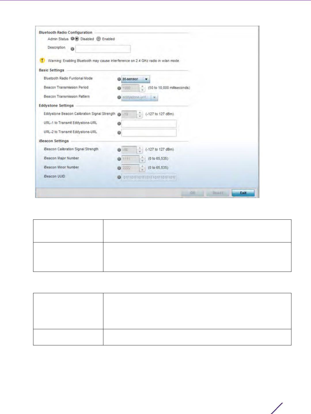
Device Configuration
Wireless Controller and Service Platform System Reference Guide 5 - 112
Figure 5-60 Profile Overrides - Bluetooth screen
8 Set the following Bluetooth Radio Configuration parameters:
9 Set the following Basic Settings:
Admin Status Enable or Disable Bluetooth support capabilities for AP-8432 or AP-
8533 model Access Point Bluetooth radio transmissions. The default
value is disabled.
Description Define a 64 character maximum description for the Access Point’s
Bluetooth radio to differentiate this radio interface from other
Bluetooth supported radio’s that may be members of the same RF
Domain.
Bluetooth Radio
Functional Mode
Set the Access Point’s Bluetooth radio functional mode to either bt-
sensor or le-beacon. Use bt-sensor mode for ADSP Bluetooth classic
sensing. Use le-beacon mode to have the Access Point transmit both
ibeacon and Eddystone-URL low energy beacons. le-beacon is the
default setting.
Beacon Transmission
Period
Set the Bluetooth radio’s beacon transmission period from 100 - 10,000
milliseconds. The default setting is 1,000 milliseconds.

Device Configuration
Wireless Controller and Service Platform System Reference Guide 5 - 113
10 Define the following Eddystone_Settings if the Beacon Transmission Pattern has been set to either
eddystone_url_1 or eddystone_url_2:
11 Define the following iBeacon_Settings if the Beacon Transmission Pattern has been set to iBeacon:
12 Select OK to save the changes to the Bluetooth configuration. Select Reset to revert to the last saved
configuration. Saved configurations are persistent across reloads.
Beacon Transmission
Pattern
When the Bluetooth radio’s mode is set to le-beacon, use the enabled
drop-down menu to set the beacon’s emitted transmission pattern to
either eddystone_url1, eddystone_url2 or ibeacon. An eddystone-URL
frame broadcasts a URL using a compressed encoding scheme to
better fit within a limited advertisement packet. Once decoded, the
URL can be used by a client for Internet access. iBeacon was created
by Apple for use in iOS devices (beginning with iOS version 7.0). There
are three data fields Apple has made available to iOS applications, a
UUID for device identification, a Major value for device class and a
Minor value for more refined information like product category.
Eddystone Beacon
Calibration Signal
Strength
Set the eddystone beacon measured calibration signal strength, from -
127 to 127 dBm, at 0 meters. Mobile devices can approximate their
distance to beacons based on received signal strength. However,
distance readings can fluctuate since they depend on several external
factors. The closer you are to a beacon, the more accurate the
reported distance. This setting is the projected calibration signal
strength at 0 meters. The default setting is -19 dBm.
URL-1 to Transmit
Eddystone-URL
Enter a 64 character maximum eddystone-URL1. The URL must be 18
characters or less once auto-encoding is applied. The encoding process
is for getting the URL to fit within the beacon’s payload.
URL-2 to Transmit
Eddystone-URL
Enter a 64 character maximum eddystone-URL2. The URL must be 18
characters or less once auto-encoding is applied. The encoding process
is for getting the URL to fit within the beacon’s payload.
iBeacon Calibration
Signal Strength
Set the ibeacon measured calibration signal strength, from -127 to 127
dBm, at 1 meter. Mobile devices can approximate their distance to
beacons based on received signal strength. However, distance readings
can fluctuate since they depend on several external factors. The closer
you are to a beacon, the more accurate the reported distance. This
setting is the projected calibration signal strength at 1 meter. The
default setting is -60 dBm.
iBeacon Major Number Set the iBeacon Major value from 0 - 65,535. Major values identify
and distinguish groups. For example, each beacon on a specific floor in
a building could be assigned a unique major value. The default is 1,111.
iBeacon Minor Number Set the iBeacon Minor value from 0 - 65,535. Minor values identify and
distinguish individual beacons. Minor values help identify individual
beacons within a group of beacons assigned a major value. The
default setting is 2,222.
iBeacon UUID Define a 32 hex character maximum UUID. The Universally Unique
IDentifier (UUID) classification contains 32 hexadecimal digits. The
UUID distinguishes iBeacons in the network from all other beacons in
networks outside of your direct administration.

Device Configuration
Wireless Controller and Service Platform System Reference Guide 5 - 114
5.2.8 Overriding a Profile’s Network Configuration
Profile Overrides
Setting a profile’s network configuration is a large task comprised of numerous administration activities. Each of
the activities described below can have an override applied to the original profile configuration. Applying an
override removes the device from the profile configuration that may be shared by other devices and requires
careful administration to ensure this one device still supports the deployment requirements within the managed
network.
A profile’s network configuration process consists of the following:
•Overriding a Profile’s DNS Configuration
•Overriding a Profile’s ARP Configuration
•Overriding a Profile’s L2TPV3 Configuration
•Overriding a Profile’s GRE Configuration
•Overriding a Profile’s IGMP Snooping Configuration
•Overriding a Profile’s MLD Snooping Configuration
•Overriding a Profile’s Quality of Service (QoS) Configuration
•Overriding a Profile’s Spanning Tree Configuration
•Overriding a Profile’s Routing Configuration
•Overriding a Profile’s Dynamic Routing (OSPF) Configuration
•Overriding a Profile’s Border Gateway Protocol (BGP) Configuration
•Overriding a Profile’s Forwarding Database Configuration
•Overriding a Profile’s Bridge VLAN Configuration
•Overriding a Profile’s Cisco Discovery Protocol Configuration
•Overriding a Profile’s Link Layer Discovery Protocol Configuration
•Overriding a Profile’s Miscellaneous Network Configuration
•Overriding a Profile’s Network Alias Configuration
•Overriding a Profile’s IPv6 Neighbor Configuration
5.2.8.1 Overriding a Profile’s DNS Configuration
Overriding a Profile’s Network Configuration
Domain Naming System (DNS) DNS is a hierarchical naming system for resources connected to the Internet or a
private network. Primarily, the controller or service platform’s DNS resources translate domain names into IP
addresses. If a DNS server doesn't know how to translate a particular domain name, it asks another one until the
correct IP address is returned. DNS enables access to resources using human friendly notations. DNS converts
human friendly domain names into notations used by networking equipment for locating resources.
As a resource is accessed (using human-friendly hostnames), it’s possible to access the resource even if the
underlying machine friendly notation name changes. Without DNS you need to remember a series of numbers
(123.123.123.123) instead of a domain name (www.domainname.com).
Controllers and service platforms maintain their own DNS facility that can assist in domain name translation. A
DNS assignment can be overridden as needed, but removes the device configuration from the managed profile
that may be shared with other similar device models.
To define the DNS configuration or apply overrides to an existing configuration:
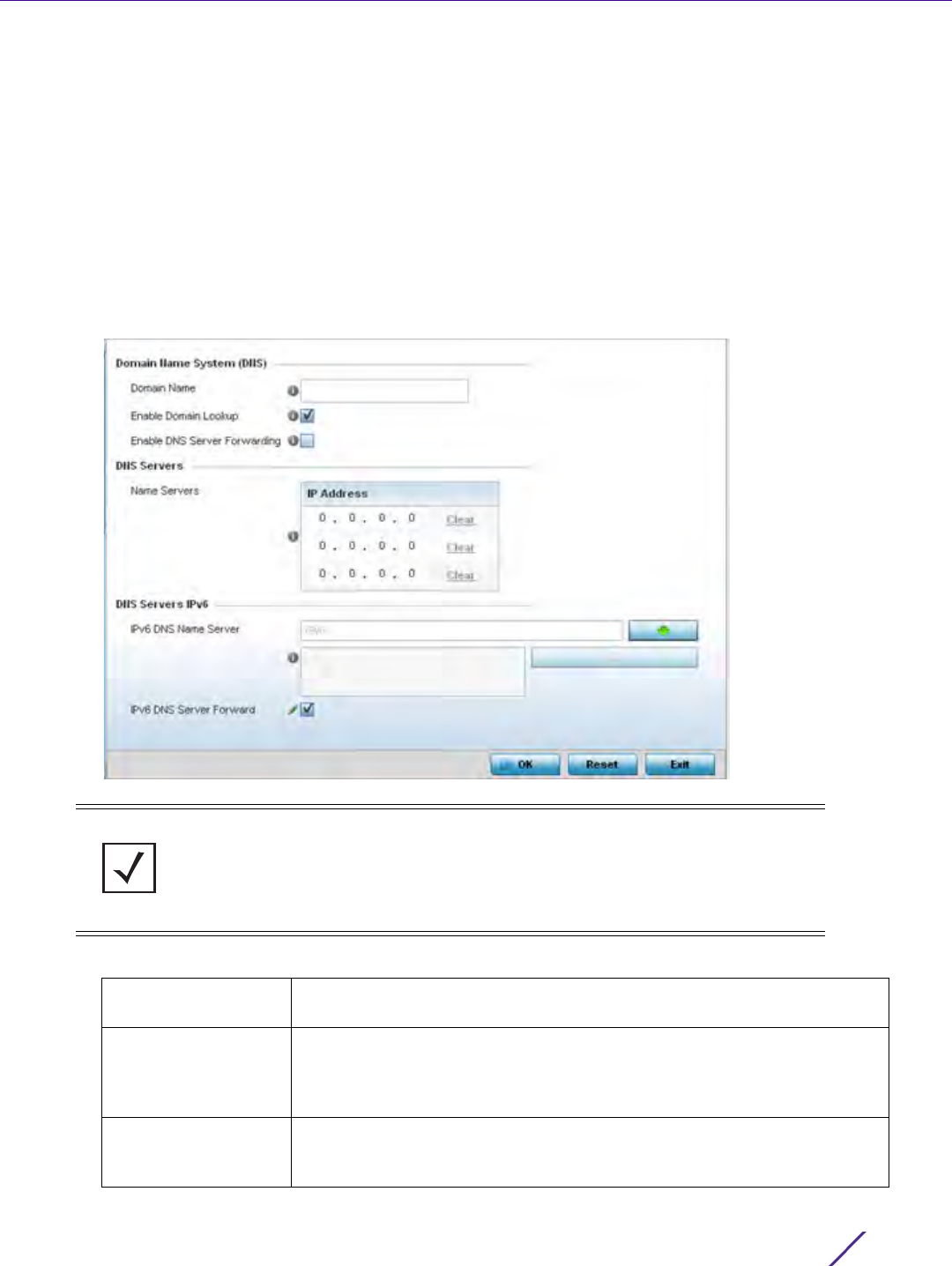
Device Configuration
Wireless Controller and Service Platform System Reference Guide 5 - 115
1Select
Devices from the Configuration tab.
The Device Configuration screen displays a list of managed devices or peer controllers, service platforms or
Access Points.
2 Select a target device (by double-clicking it) from amongst those displayed within the Device Configuration
screen.
Devices can also be selected directly from the Device Browser in the lower, left-hand, side of the UI.
3Select
Profile Overrides from the Device menu to expand it into sub menu options.
4Select
Network to expand its sub menu options.
5Select
DNS.
Figure 5-61 Profile Overrides - Network DNS screen
6 Set or override the following Domain Name System (DNS) configuration data:
NOTE: A blue override icon (to the left of a parameter) defines the parameter as
having an override applied. To remove an override go to the Basic Configuration
section of the device and click the Clear Overrides button. This removes all
overrides from the device.
Domain Name Provide or override the default Domain Name used to resolve DNS names.
The name cannot exceed 64 characters.
Enable Domain
Lookup
Select this option to enable DNS on the controller or service platform.
When enabled, the controller or service platform can convert human
friendly domain names into numerical IP destination addresses. This
option is selected by default.
Enable DNS Server
Forwarding
Click to enable the forwarding of DNS queries to external DNS servers if a
DNS query cannot be processed by the controller or service platform’s
own DNS resources. This feature is disabled by default.

Device Configuration
Wireless Controller and Service Platform System Reference Guide 5 - 116
7 Set or override the following DNS Server configuration data:
8 Set the following DNS Servers IPv6 configuration data when using IPv6:
9Select
OK to save the changes and overrides made to the DNS configuration. Select Reset to revert to the last
saved configuration.
5.2.8.2 Overriding a Profile’s ARP Configuration
Overriding a Profile’s Network Configuration
Address Resolution Protocol (ARP) is a protocol for mapping an IP address to a hardware MAC address recognized
on the managed network. ARP provides rules for making this correlation and providing address conversion in both
directions. ARP assignment s can be overridden as needed, but an override removes the device configuration from
the managed profile that may be shared with other similar device models.
When an incoming packet destined for a host arrives at the controller or service platform, the gateway uses ARP
to find a physical host or MAC address that matches the IP address. ARP looks in its ARP cache and, if it finds the
address, provides it so the packet can be converted to the right packet length and format and sent to the
destination. If no entry is found for the IP address, ARP broadcasts a request packet in a special format to all the
machines on the LAN to see if one machine knows that it has that IP address associated with it. A machine that
recognizes the IP address as its own returns a reply so indicating. ARP updates the ARP cache for future reference
and then sends the packet to the MAC address that replied.
To define an ARP supported configuration on a controller or service platform:
1Select
Devices from the Configuration tab.
The Device Configuration screen displays a list of managed devices or peer controllers, service platforms or
Access Points.
2 Select a target device (by double-clicking it) from amongst those displayed within the Device Configuration
screen.
Devices can also be selected directly from the Device Browser in the lower, left-hand, side of the UI.
3Select
Profile Overrides from the Device menu to expand it into sub menu options.
4Select
Network to expand its sub menu options.
Name Servers Provide a list of up to three DNS servers to forward DNS queries if the
controller or service platform’s DNS resources are unavailable. DNS name
servers are used to resolve IP addresses. Use the Clear link next to each
DNS server to clear the DNS name server’s IP address from the list.
IPv6 DNS Name
Server
Provide the default domain name used to resolve IPv6 DNS names. When
an IPv6 host is configured with the address of a DNS server, the host
sends DNS name queries to the server for resolution. A maximum of three
entries are permitted.
IPv6 DNS Server
Forward
Select the check box to enable IPv6 DNS domain names to be converted
into numerical IP destination addresses. The setting is disabled by default.
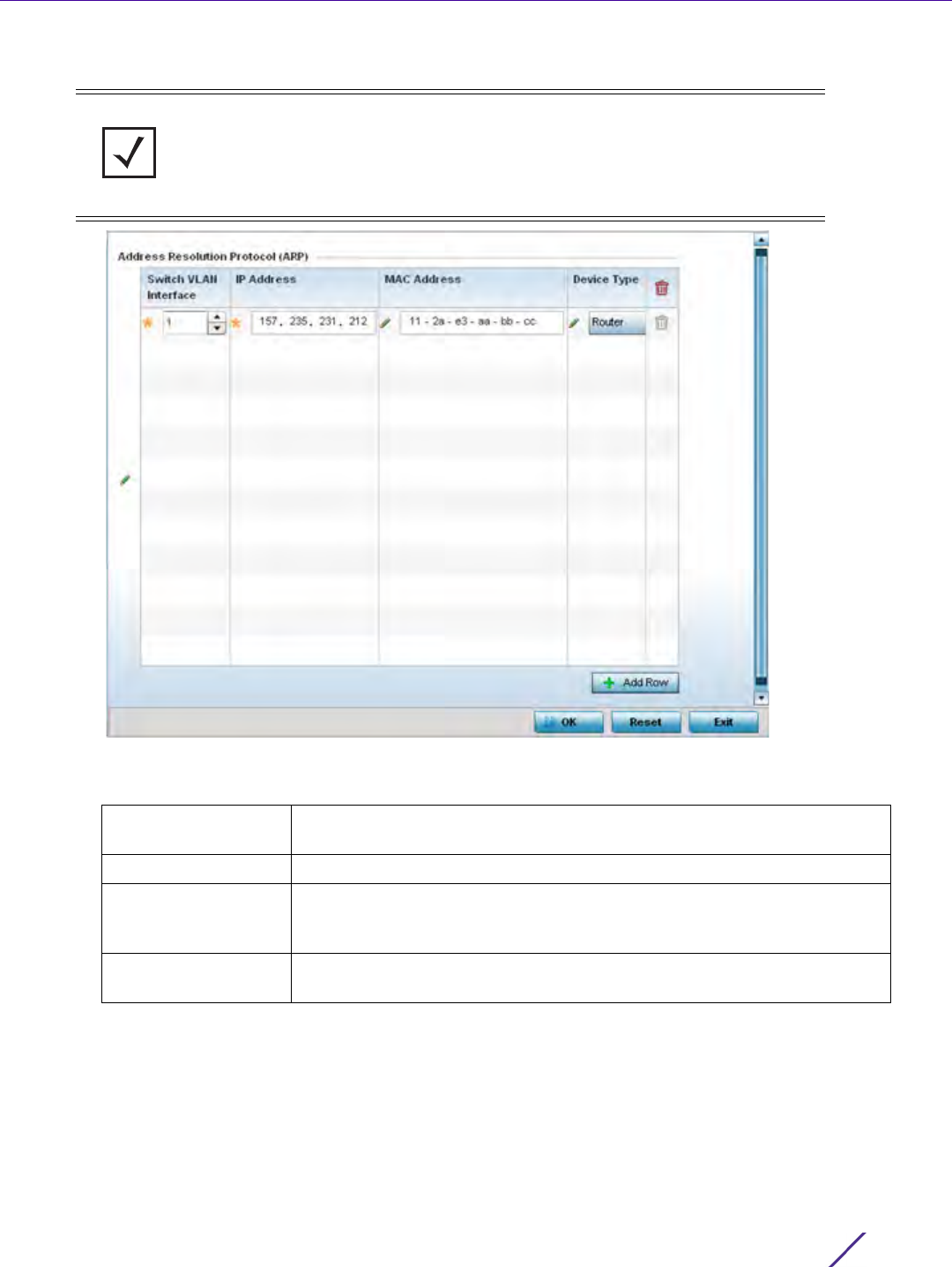
Device Configuration
Wireless Controller and Service Platform System Reference Guide 5 - 117
5Select
ARP.
Figure 5-62 Profile Overrides - Network ARP screen
6 Set or override the following parameters to define the controller or service platform’s ARP configuration:
7 To add additional ARP overrides click on the + Add Row button and enter the configuration information in the
table above.
8 Select the OK button to save the changes and overrides to the ARP configuration. Select Reset to revert to the
last saved configuration.
NOTE: A blue override icon (to the left of a parameter) defines the parameter as
having an override applied. To remove an override go to the Basic Configuration
section of the device and click the Clear Overrides button. This removes all
overrides from the device.
Switch VLAN
Interface
Use the spinner control to select a VLAN interface (1 - 4094) for an
address requiring resolution.
IP Address Define the IP address used to fetch a MAC address.
MAC Address Displays the target MAC address that’s subject to resolution. This is the
MAC used for mapping an IP address to a MAC address that’s recognized
on the network.
Device Type Specify the device type the ARP entry supports. Host is the default
setting.
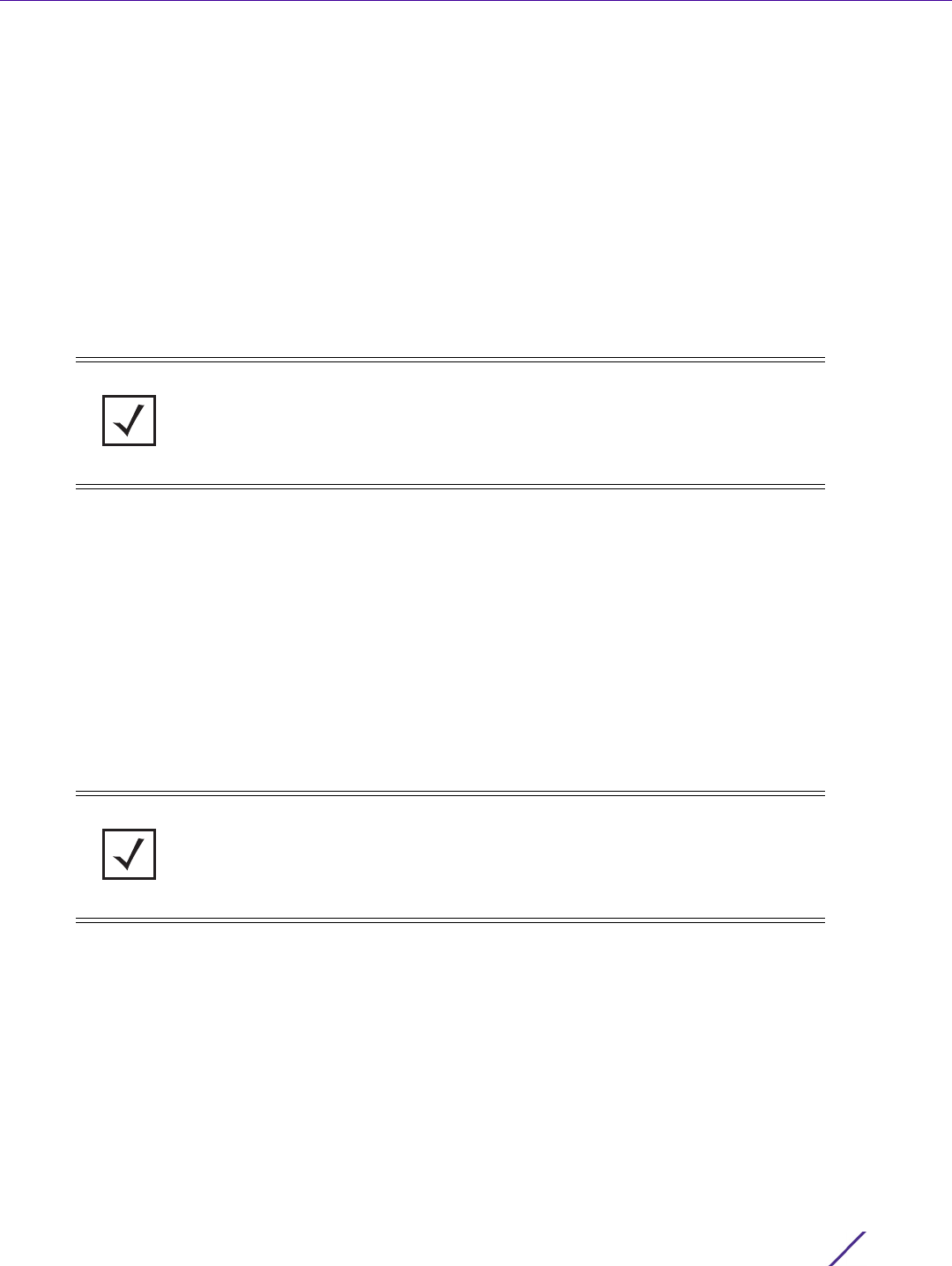
Device Configuration
Wireless Controller and Service Platform System Reference Guide 5 - 118
5.2.8.3 Overriding a Profile’s L2TPV3 Configuration
Overriding a Profile’s Network Configuration
L2TP V3 is a standard used for transporting different types of layer 2 frames in an IP network (and Access Point
profile). L2TP V3 defines control and encapsulation protocols for tunneling layer 2 frames between two IP nodes.
Use L2TP V3 to create tunnels for transporting layer 2 frames. L2TP V3 enables controllers, service platforms and
Access Points to create tunnels for transporting Ethernet frames to and from bridge VLANs and physical ports.
L2TP V3 tunnels can be defined between WING devices and other vendor devices supporting the L2TP V3
protocol.
Multiple pseudowires can be created within an L2TP V3 tunnel. WING supported access points support an Ethernet
VLAN pseudowire type exclusively.
Ethernet VLAN pseudowires transport Ethernet frames to and from a specified VLAN. One or more L2TP V3
tunnels can be defined between tunnel end points. Each tunnel can have one or more L2TP V3 sessions. Each
tunnel session corresponds to one pseudowire. An L2TP V3 control connection (a L2TP V3 tunnel) needs to be
established between the tunneling entities before creating a session.
For optimal pseudowire operation, both the L2TP V3 session originator and responder need to know the
psuedowire type and identifier. These two parameters are communicated during L2TP V3 session establishment.
An L2TP V3 session created within an L2TP V3 connection also specifies multiplexing parameters for identifying a
pseudowire type and ID.
The working status of a pseudowire is reflected by the state of the L2TP V3 session. If a L2TP V3 session is down,
the pseudowire associated with it must be shut down. The L2TP V3 control connection keep-alive mechanism can
serve as a monitoring mechanism for the pseudowires associated with a control connection.
To define an L2TPV3 configuration for an Access Point profile:
1Select
Devices from the Configuration tab.
The Device Configuration screen displays a list of managed devices or peer controllers, service platforms or
Access Points.
2 Select a target device (by double-clicking it) from amongst those displayed within the Device Configuration
screen.
Devices can also be selected directly from the Device Browser in the lower, left-hand, side of the UI.
3Select
Profile Overrides from the Device menu to expand it into sub menu options.
4Expand the Network menu and select L2TPv3.
NOTE: A pseudowire is an emulation of a layer 2 point-to-point connection over a
packet-switching network (PSN). A pseudowire was developed out of the necessity
to encapsulate and tunnel layer 2 protocols across a layer 3 network.
NOTE: If connecting an Ethernet port to another Ethernet port, the pseudowire
type must be Ethernet port, if connecting an Ethernet VLAN to another Ethernet
VLAN, the pseudowire type must be Ethernet VLAN.
Device Configuration
Wireless Controller and Service Platform System Reference Guide 5 - 119
5The
General tab displays by default with additional L2RPv3 Tunnel and Manual Session tabs available.
Figure 5-63 Network - L2TPv3 screen, General tab
6 Set the following General Settings for an L2TPv3 profile configuration:
7 Set the following Logging Settings for a L2TPv3 profile configuration:
Hostname Define a 64 character maximum host name to specify the name of the
host that’s sent tunnel messages. Tunnel establishment involves
exchanging 3 message types (SCCRQ, SCCRP and SCCN) with the peer.
Tunnel IDs and capabilities are exchanged during the tunnel
establishment with the host.
Router ID Set either the numeric IP address or the integer used as an identifier for
tunnel AVP messages. AVP messages assist in the identification of a
tunnelled peer.
UDP Listen Port Select this option to set the port used for listening to incoming traffic.
Select a port from 1,024 - 65,535.
Tunnel Bridging Select this option to enable or disable bridge packets between two tunnel
end points. This setting is disabled by default.
Enable Logging Select this option to enable the logging of Ethernet frame events to and
from bridge VLANs and physical ports on a defined IP address, host or
router ID. This setting is disabled by default.
IP Address Optionally use a peer tunnel ID address to capture and log L2TPv3
events. Use Any to log any IP address.
Hostname If not using an IP address for event logging, optionally use a peer tunnel
hostname to capture and log L2TPv3 events. Use Any to log any
hostname. Hostnames cannot include an underscore character.

Device Configuration
Wireless Controller and Service Platform System Reference Guide 5 - 120
8 Select the L2TPV3 Tunnel tab.
Figure 5-64 Network - L2TPv3 screen, T2TP tunnel tab
9 Review the following L2TPv3 tunnel configuration data:
Router ID If not using an IP address or a hostname for event logging, use a router ID
to capture and log L2TPv3 events. Use Any to log any router ID.
Name Displays the name of each listed L2TPv3 tunnel assigned upon creation.
Local IP Address Lists the IP address assigned as the local tunnel end point address, not
the interface IP address. This IP is used as the tunnel source IP address. If
this parameter is not specified, the source IP address is chosen
automatically based on the tunnel peer IP address.
MTU Displays the maximum transmission unit (MTU) size for each listed tunnel.
The MTU is the size (in bytes) of the largest protocol data unit that the
layer can pass between tunnel peers.
Use Tunnel Policy Lists the L2TPv3 tunnel policy assigned to each listed tunnel.
Local Hostname Lists the tunnel specific hostname used by each listed tunnel. This is the
host name advertised in tunnel establishment messages.
Local Router ID Specifies the router ID sent in tunnel establishment messages.
Establishment
Criteria
Specifies the criteria required for a tunnel between two peers.
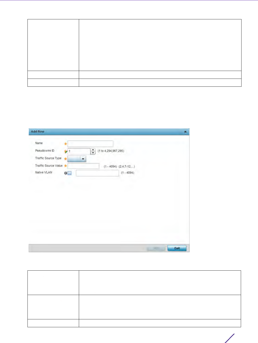
Device Configuration
Wireless Controller and Service Platform System Reference Guide 5 - 121
10 Either select Add to create a new L2TPv3 tunnel configuration, Edit to modify an existing tunnel configuration
or Delete to remove a tunnel from those available to this profile.
11 If creating a new tunnel configuration, assign it a 31 character maximum Name.
12 Select + Add Row to populate the table with configurable session parameters for this tunnel configuration.
Figure 5-65 Network - L2TPv3 screen, Add L2TPv3 Tunnel Configuration
13 Define the following Session parameters required for the L2TPv3 tunnel configuration:
Critical Resource Specifies the critical resource that should exist for a tunnel between two
peers. Critical resources are device IP addresses or interface destinations
interopreted as critical to the health of the network. Critical resources
allow for the continuous monitoring of these defined addresses. A critical
resource, if not available, can result in the network suffering performance
degradation. A critical resource can be a gateway, AAA server, WAN
interface or any hardware or service on which the stability of the network
depends. Critical resources are pinged regularly. If there’s a connectivity
issue, an event is generated stating a critical resource is unavailable.
Peer IP Address Specifies the IP address of the tunnel destination peer device.
Hostname Specifies the administrator assigned hostname of the tunnel.
Name Enter a 31 character maximum session name. There is no idle timeout for
a tunnel. A tunnel is not usable without a session and a subsequent
session name.The tunnel is closed when the last session tunnel session is
closed.
Pseudowire ID Define a psuedowire ID for this session. A pseudowire is an emulation of a
layer 2 point-to-point connection over a packet-switching network (PSN).
A pseudowire was developed out of the necessity to encapsulate and
tunnel layer 2 protocols across a layer 3 network.
Traffic Source Type Lists the type of traffic tunnelled in this session (VLAN etc).
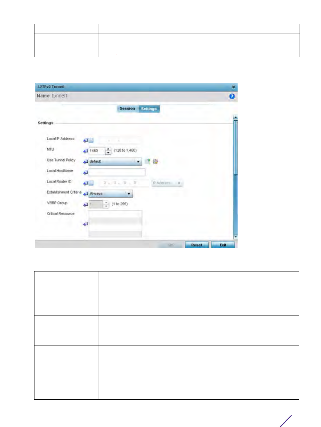
Device Configuration
Wireless Controller and Service Platform System Reference Guide 5 - 122
14 Select OK to save the updates to Exit to revert to the last configuration.
15 Select the Settings tab.
Figure 5-66 Network - L2TPv3 screen, Settings
16 Define the following Settings required for the L2TPv3 tunnel configuration:
Traffic Source Value Define a VLAN range to include in the tunnel session.
Native VLAN Select this option to provide a VLAN ID that will not be tagged in tunnel
establishment and packet transfer. Available VLAN ranges are from 1 -
4,094.
Local IP Address Enter the IP address assigned as the local tunnel end point address, not
the interface IP address. This IP is used as the tunnel source IP address. If
this parameter is not specified, the source IP address is chosen
automatically based on the tunnel peer IP address. This parameter is
applicable when establishing the tunnel and responding to incoming
tunnel create requests.
MTU Set the maximum transmission unit (MTU). The MTU is the size (in bytes)
of the largest protocol data unit the layer can pass between tunnel peers.
Define a MTU from 128 - 1,460 bytes. The default setting is 1,460. A larger
MTU means processing fewer packets for the same amount of data.
Use Tunnel Policy Select the L2TPv3 tunnel policy. The policy consists of user defined values
for protocol specific parameters which can be used with different tunnels.
If none is available, a new policy can be created or an existing one can be
modified.
Local Hostname Provide the tunnel specific hostname used by this tunnel. This is the host
name advertised in tunnel establishment messages. Hostnames cannot
include an underscore character.

Device Configuration
Wireless Controller and Service Platform System Reference Guide 5 - 123
17 Define the following Rate Limit settings for the L2TP tunnel configuration. Rate limiting manages the maximum
rate sent to or received from L2TPv3 tunnel members.
18 Refer to the Peer table to review the configurations of the peers destinations for tunnel connection.
19 Select + Add Row to populate the table with a maximum of two peer configurations.
Local Router ID Specify the router ID sent in tunnel establishment messages with a target
peer device.
Establishment
Criteria
Specify the establishment criteria for creating a tunnel. The tunnel is only
created if this device is one of the following:
vrrp-master
cluster-master
rf-domain-manager
The tunnel is always created if Always is selected. This indicates the
device need not be any one of the above three (3) to establish a tunnel.
VRRP Group Set the VRRP group ID. VRRP groups is only enabled when the
Establishment Criteria is set to vrrp-master.
Critical Resource The Critical Resources table lists important resources defined for this
system. The tunnel is created and maintained only if these critical
resources are available. The tunnel is removed if any one of the defined
resources goes down or is unreachable.
Session Name Use the drop-down menu to select the tunnel session that will have the
direction, burst size and traffic rate settings applied.
Direction Select the direction for L2TPv3 tunnel traffic rate limiting. Egress traffic is
outbound L2TPv3 tunnel data coming to the controller, service platform
or Access Point. Ingress traffic is inbound L2TPv3 tunnel data coming to
the controller, service platform or Access Point.
Maximum Burst Size Set the maximum burst size for egress or ingress traffic rate limiting
(depending on which direction is selected) on a L2TPv3 tunnel. Set a
maximum burst size between 2 - 1024 kbytes. The smaller the burst, the
less likely the upstream packet transmission will result in congestion for
L2TPv3 tunnel traffic. The default setting is 320 bytes.
Rate Set the data rate (from 50 - 1,000,000 kbps) for egress or ingress traffic
rate limiting (depending on which direction is selected) for an L2TPv3
tunnel. The default setting is 5000 kbps.
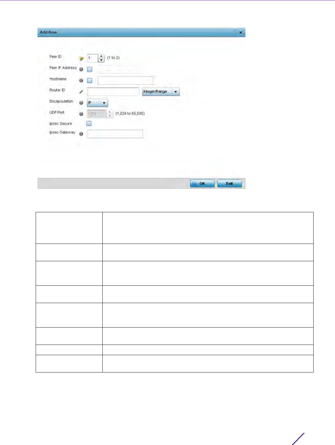
Device Configuration
Wireless Controller and Service Platform System Reference Guide 5 - 124
Figure 5-67 Network - L2TPv3 screen, Add Peer Configuration
20 Define the following Peer parameters:
Peer ID Define the primary peer ID used to set the primary and secondary peer
for tunnel fail over. If the peer is not specified, tunnel establishment does
not occur. However, if a peer tries to establish a tunnel with this Access
Point, it creates the tunnel if the hostname and/or Router ID matches.
Peer IP Address Select this option to enter the numeric IP address used as the destination
peer address for tunnel establishment.
Hostname Assign the peer a hostname that can be used as matching criteria in the
tunnel establishment process. Hostnames cannot include an underscore
character.
Router ID Specify the router ID sent in tunnel establishment messages with this
specific peer.
Encapsulation Select either IP or UDP as the peer encapsulation protocol. The default
setting is IP. UDP uses a simple transmission model without implicit
handshakes.
IPSec Secure Enable this option to enable security on the connection between the
Access Point and Virtual Controller.
IPSec Gateway Specify the IP Address of the IPSec Secure Gateway.
UDP Port If UDP encapsulation is selected, use the spinner control to define the
UDP encapsulation port.
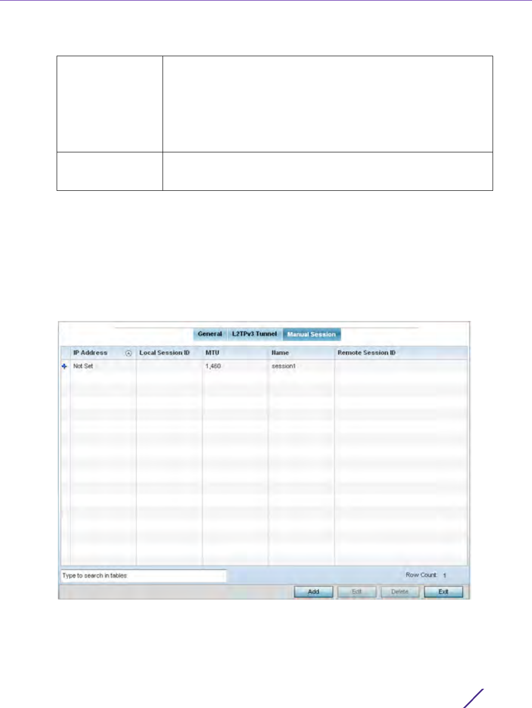
Device Configuration
Wireless Controller and Service Platform System Reference Guide 5 - 125
21 From back at the Settings tab, set the following Fast Failover parameters.
22 Select OK to save the peer configuration.
23 Select OK to save the changes within the T2TP Tunnel screen. Select Reset to revert the screen to its last saved
configuration.
24 Select the Manual Session tab.
Individual sessions can be created after a successful tunnel connection and establishment. Each session is a
single data stream. After successful session establishment, data corresponding to that session (pseudowire)
can be transferred. If a session is down, the pseudowire associated with it is shut down as well.
Figure 5-68 Network - L2TPv3 screen, Manual Session tab
Enable When enabled, the device starts sending tunnel requests on both peers,
and in turn, establishes the tunnel on both peers. If disabled, tunnel
establishment only occurs on one peer, with failover and other
functionality the same as legacy behavior. If fast failover is enabled after
establishing a single tunnel the establishment is restarted with two peers.
One tunnels defined as active and the other standby. Both tunnels
perform connection health checkups with individual hello intervals. This
setting is disabled by default.
Enable Aggressive
Mode
When enabled, tunnel initiation hello requests are set to zero. For failure
detections, hello attempts are not retried, regardless of defined retry
attempts. This setting is disabled by default.
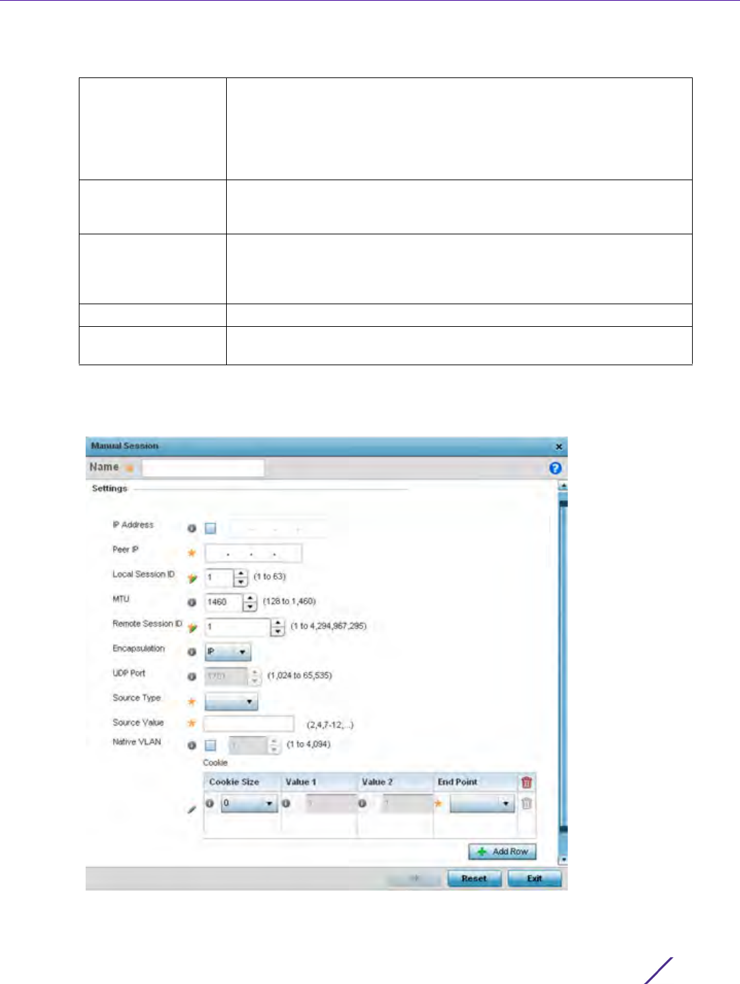
Device Configuration
Wireless Controller and Service Platform System Reference Guide 5 - 126
25 Refer to the following manual session configurations to determine whether one should be created or modified:
26 Select Add to create a new manual session, Edit to modify an existing session configuration or Delete to
remove a selected manual session.
Figure 5-69 Network - L2TPv3 screen, Add T2TP Peer Configuration
IP Address Lists the IP address assigned as the local tunnel end point address, not
the interface IP address. This IP is used as the tunnel source IP address. If
this parameter is not specified, the source IP address is chosen
automatically based on the tunnel peer IP address. This parameter is
applicable when establishing the session and responding to incoming
requests.
Local Session ID Displays the numeric identifier assigned to each listed tunnel session. This
is the pseudowire ID for the session. This pseudowire ID is sent in a
session establishment message to the L2TP peer.
MTU Displays each sessions’s maximum transmission unit (MTU). The MTU is
the size (in bytes) of the largest protocol data unit the layer can pass
between tunnel peers in this session. A larger MTU means processing
fewer packets for the same amount of data.
Name Lists the name assigned to each listed manual session.
Remote Session ID Lists the remote session ID passed in the establishment of the tunnel,
used a a unique identifier for this tunnel session.

Device Configuration
Wireless Controller and Service Platform System Reference Guide 5 - 127
27 Set the following session parameters:
28 Select the + Add Row button to set the following:
29 Select OK to save the changes to the session configuration. Select Reset to revert to the last saved
configuration.
Name Define a 31 character maximum name of this tunnel session. After a
successful tunnel connection and establishment, the session is created.
Each session name represents a single data stream.
IP Address Specify the IP address used to be as tunnel source IP address. If not
specified, the tunnel source IP address is selected automatically based on
the tunnel peer IP address. This address is applicable only for initiating the
tunnel. When responding to incoming tunnel create requests, it would use
the IP address on which it had received the tunnel create request.
Peer IP Set the IP address of an L2TP tunnel destination peer. This is the peer
allowed to establish the tunnel.
Local Session ID Set the numeric identifier for the tunnel session. This is the pseudowire ID
for the session. This pseudowire ID is sent in a session establishment
message to the L2TP peer.
MTU Define the session’s maximum transmission unit (MTU) as the size (in
bytes) of the largest protocol data unit the layer can pass between tunnel
peers in this session. A larger MTU means processing fewer packets for
the same amount of data.
Remote Session ID Use the spinner control to set the remote session ID passed in the
establishment of the tunnel and sed a a unique identifier for this tunnel
session. Assign an ID from 1 - 4,294,967,295.
Encapsulation Select either IP or UDP as the peer encapsulation protocol. The default
setting is IP. UDP uses a simple transmission model without implicit
handshakes.
UDP Port If UDP encapsulation is selected, use the spinner control to define the
UDP encapsulation port. This is the port where the L2TP service is
running.
Source Type Select a VLAN as the virtual interface source type.
Source Value Define the Source Value range (1 - 4,094) to include in the tunnel. Tunnel
session data includes VLAN tagged frames.
Native VLAN Select this option to define the native VLAN that’s not tagged.
Cookie Size Set the size of the cookie field within each L2TP data packet. Options
include 0, 4 and 8. The default setting is 0.
Value 1 Set the cookie value first word.
Value 2 Set the cookie value second word.
End Point Define whether the tunnel end point is local or remote.

Device Configuration
Wireless Controller and Service Platform System Reference Guide 5 - 128
5.2.8.4 Overriding a Profile’s GRE Configuration
Overriding a Profile’s Network Configuration
Generic routing encapsulation (GRE) tunneling can be configured to bridge Ethernet packets between WLANs and
a remote WLAN gateway over a GRE tunnel. The tunneling of 802.3 packets using GRE is an alternative to MiNT or
L2TPv3. Related features like ACLs for extended VLANs are still available using layer 2 tunneling over GRE.
Using GRE, Access Points map one or more VLANs to a tunnel. The remote endpoint is a user-configured WLAN
gateway IP address, with an optional secondary IP address should connectivity to the primary GRE peer be lost.
VLAN traffic is expected in both directions in the GRE tunnel. A WLAN mapped to these VLANs can be either
open or secure. Secure WLANs require authentication to a remote RADIUS server available within your
deployment using standard RADIUS protocols. Access Points can reach both the GRE peer as well as the RADIUS.
Previous releases supported only IPv4 tunnel end points, now support for both IPv4 or IPv6 tunnel endpoints is
available. However, a tunnel needs to contain either IPv4 or IPv6 formatted device addresses and cannot be mixed.
With the new IPv6 tunnel implementation, all outbound packets are encapsulated with the GRE header, then the
IPv6 header. The header source IP address is the local address of the IPv6 address of tunnel interface, and the
destination address peer address of the tunnel. All inbound packets are de-capsulated by removing the IPv6 and
GRE header before sending it over to the IP stack.
To define a profile’s GRE settings:
1Select
Devices from the Configuration tab.
The Device Configuration screen displays a list of managed devices or peer controllers, service platforms or
Access Points.
2 Select a target device (by double-clicking it) from amongst those displayed within the Device Configuration
screen.
Devices can also be selected directly from the Device Browser in the lower, left-hand, side of the UI.
3Select
Profile Overrides from the Device menu to expand it into sub menu options.
4Select
Network to expand its sub menu options.
5Select
GRE.
The screen displays existing GRE configurations.
6 Select the Add button to create a new GRE tunnel configuration or select an existing tunnel and select Edit to
modify its current configuration. To remove an existing GRE tunnel, select it from amongst those displayed and
select the Delete button.
NOTE: A blue override icon (to the left of a parameter) defines the parameter as
having an override applied. To remove an override, go to the Basic Configuration
section of the device and click the Clear Overrides button. This removes all
overrides from the device.
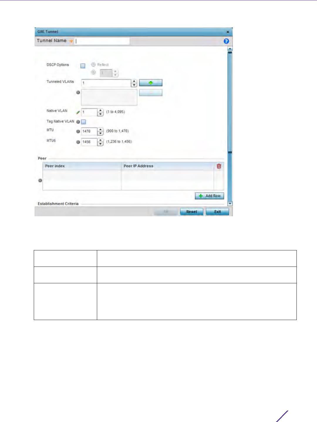
Device Configuration
Wireless Controller and Service Platform System Reference Guide 5 - 129
Figure 5-70 Profile Overrides - Network GRE screen
7 If creating a new GRE configuration, assign it a 32 character maximum name to distinguish its configuration.
8 Define the following settings for the GRE configuration:
DSCP Options Use the spinner control to set the tunnel DSCP / 802.1q priority value from
encapsulated packets to the outer packet IPv4 header.
Tunneled VLANs Define the VLAN connected clients use to route GRE tunneled traffic
within their respective WLANs.
Native VLAN Set a numerical VLAN ID (1 - 4094) for the native VLAN. The native VLAN
allows an Ethernet device to associate untagged frames to a VLAN when
no 802.1Q frame is included in the frame. Additionally, the native VLAN is
the VLAN untagged traffic is directed over when using a port in trunk
mode.

Device Configuration
Wireless Controller and Service Platform System Reference Guide 5 - 130
9The
Peer table lists the credentials of the GRE tunnel end points. Add new table rows as needed to add
additional GRE tunnel peers.
Select + Add Row to populate the table with a maximum of two peer configurations.
10 Define the following Peer parameters:
Tag Native VLAN Select this option to tag the native VLAN. The IEEE 802.1Q specification is
supported for tagging frames and coordinating VLANs between devices.
IEEE 802.1Q adds four bytes to each frame identifying the VLAN ID for
upstream devices that the frame belongs. If the upstream Ethernet device
does not support IEEE 802.1Q tagging, it does not interpret the tagged
frames. When VLAN tagging is required between devices, both devices
must support tagging and be configured to accept tagged VLANs. When
a frame is tagged, the 12 bit frame VLAN ID is added to the 802.1Q header
so upstream Ethernet devices know which VLAN ID the frame belongs to.
The device reads the 12 bit VLAN ID and forwards the frame to the
appropriate VLAN. When a frame is received with no 802.1Q header, the
upstream device classifies the frame using the default or native VLAN
assigned to the Trunk port. The native VLAN allows an Ethernet device to
associate untagged frames to a VLAN when no 802.1Q frame is included
in the frame. This feature is disabled by default.
MTU Set an IPv4 tunnel’s maximum transmission unit (MTU) from 128 - 1,476.
The MTU is the largest physical packet size (in bytes) transmittable within
the tunnel. Any messages larger than the MTU are divided into smaller
packets before being sent. A larger MTU provides greater efficiency
because each packet carries more user data while protocol overheads,
such as headers or underlying per-packet delays, remain fixed; the
resulting higher efficiency means a slight improvement in bulk protocol
throughput. A larger MTU results in the processing of fewer packets for
the same amount of data. For IPv4, the overhead is 24 bytes (20 bytes
IPv4 header + 4 bytes GRE Header), thus the default setting for an IPv4
MTU is 1,476.
MTU6 Set an IPv6 tunnel’s MTU from 128 - 1,456. The MTU is the largest physical
packet size (in bytes) transmit able within the tunnel. Any messages
larger than the MTU are divided into smaller packets before being sent. A
larger MTU provides greater efficiency because each packet carries more
user data while protocol overheads, such as headers or underlying per-
packet delays, remain fixed; the resulting higher efficiency means a slight
improvement in bulk protocol throughput. A larger MTU results in the
processing of fewer packets for the same amount of data. For IPv6, the
overhead is 44 bytes (40 bytes IPv6 header + 4 bytes GRE header), thus
the default setting for an IPv6 MTU is 1,456.
Peer Index Assign a numeric index to each peer to help differentiate tunnel end
points.

Device Configuration
Wireless Controller and Service Platform System Reference Guide 5 - 131
11 Set the following Establishment Criteria for the GRE tunnel configuration:
12 Define or override the following Failover parameters to apply to the GRE tunnel configuration:
13 Select the OK button to save the changes and overrides to the GRE configuration. Select Reset to revert to the
last saved configuration.
5.2.8.5 Overriding a Profile’s IGMP Snooping Configuration
Overriding a Profile’s Network Configuration
The Internet Group Management Protocol (IGMP) is used for managing IP multicast group members. The controller
or service platform listens to IGMP network traffic and forwards the IGMP multicast packets to radios on which the
Peer IP Address Define the IP address of the added GRE peer to serve as a network
address identifier. Designate whether the IP is formatted as an IPv4 or
IPv6 address. IPv4 is a connectionless protocol for packet switched
networking. IPv4 operates as a best effort delivery method, as it does not
guarantee delivery, and does not ensure proper sequencing or duplicate
delivery (unlike TCP). IPv4 hosts can use link local addressing to provide
local connectivity. IPv6 is the latest revision of the Internet Protocol (IP)
designed to replace IPv4. IPV6 provides enhanced identification and
location information for computers on networks routing traffic across the
Internet. IPv6 addresses are eight groups of four hexadecimal digits
separated by colons.
Criteria Specify the establishment criteria for creating a GRE tunnel. In a multi-
controller within a RF domain, it’s always the master node with which the
tunnel is established. The tunnel is only created if the tunnel device is
designated one of the following:
vrrp-master
cluster-master
rf-domain-manager
The tunnel is automatically created if Always (default setting) is selected.
This indicates the device need not be any one of the above three (3) to
establish a tunnel.
VRRP Group Set the VRRP group ID only enabled when the Establishment Criteria is
set to vrrp-master. A virtual router redundancy group (VRRP) enables the
creation of a group of routers as a default gateway for redundancy.
Clients can point to the IP address of the VRRP virtual router as their
default gateway and utilize a different group member if a master
becomes unavailable.
Enable Failover Select this option to periodically ping the primary gateway to assess its
availability. If the primary gateway is unreachable.
Ping Interval Set the duration between two successive pings to the gateway. Define
this value in seconds from 1 - 21,600.
Number of Retries Set the number of ping retries (from 1 - 63) when no response is received
before the session is terminated.
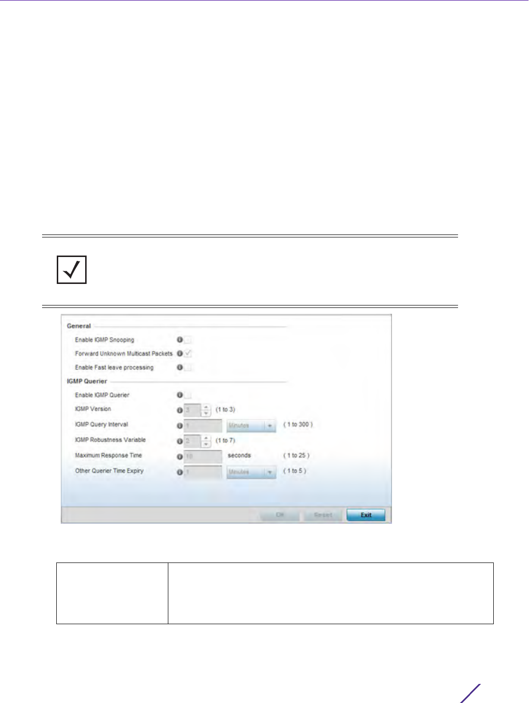
Device Configuration
Wireless Controller and Service Platform System Reference Guide 5 - 132
interested hosts are connected. On the wired side of the network, the controller or service platform floods all the
wired interfaces. This feature reduces unnecessary flooding of multicast traffic in the network.
To define a Profile’s IGMP settings:
1Select
Devices from the Configuration tab.
The Device Configuration screen displays a list of managed devices or peer controllers, service platforms or
Access Points.
2 Select a target device (by double-clicking it) from amongst those displayed within the Device Configuration
screen.
Devices can also be selected directly from the Device Browser in the lower, left-hand, side of the UI.
3Select
Profile Overrides from the Device menu to expand it into sub menu options.
4Select
Network to expand its sub menu options.
5Select
IGMP Snooping.
Figure 5-71 Profile Overrides - Network IGMP Snooping
6 Define or override the following General IGMP Snooping parameters for the bridge VLAN configuration:
NOTE: A blue override icon (to the left of a parameter) defines the parameter as
having an override applied. To remove an override, go to the Basic Configuration
section of the device and click the Clear Overrides button. This removes all
overrides from the device.
Enable IGMP Snooping Select this option to enable IGMP snooping. If disabled, snooping on a
per VLAN basis is also disabled. This feature is enabled by default. If
disabled, the settings under the bridge configuration are overridden. For
example, if IGMP snooping is disabled, but the bridge VLAN is enabled,
the effective setting is disabled.

Device Configuration
Wireless Controller and Service Platform System Reference Guide 5 - 133
7 Set or override the following IGMP Querier parameters for the profile’s bridge VLAN configuration:
8 Select the OK button to save the changes and overrides to the IGMP Snooping tab. Select Reset to revert to the
last saved configuration.
Forward Unknown
Multicast Packets
Select this option to enable the forwarding of multicast packets from
unregistered multicast groups. If disabled (the default setting), the
unknown multicast forward feature is also disabled for individual VLANs.
Enable Fast leave
processing
Select this option to remove a Layer 2 LAN interface from the IGMP
snooping forwarding table entry without initially sending IGMP group-
specific queries to the interface. When receiving a group-specific
IGMPv2 leave message, IGMP snooping removes the interface from the
Layer 2 forwarding table entry for that multicast group, unless a
multicast router was learned on the port. Fast-leave processing
enhances bandwidth management for all hosts on the network.
Enable IGMP Querier Select this option to enable IGMP querier. IGMP snoop querier is used to
keep host memberships alive. It’s primarily used in a network where
there’s a multicast streaming server and hosts subscribed to the server
and no IGMP querier present. An IGMP querier sends out periodic IGMP
query packets. Interested hosts reply with an IGMP report packet. IGMP
snooping is only conducted on wireless radios. IGMP multicast packets
are flooded on wired ports. IGMP multicast packet are not flooded on
the wired port. IGMP membership is also learnt on it and only if present,
then it is forwarded on that port.
IGMP Version Use the spinner control to set the IGMP version compatibility to either
version 1, 2 or 3. IGMPv1 is defined by RFC 1112, IGMPv2 is defined by
RFC 2236 and IGMPv3 defined by RFC 4604 which defines both IGMPv3
and MLDv2. IGMPv2 improves over IGMPv1 by adding the ability for a
host to signal desire to leave a multicast group. IGMPv3 improves over
IGMPv2 by adding the ability to listen to multicast traffic originating
from a set of source IP addresses exclusively. The default setting is 3.
IGMP Query Interval Set the interval IGMP queries are made. Options include Seconds
(1 - 18,000), Minutes (1 - 300) and Hours (1 - 5). The default setting is
one minute.
IGMP Robustness
Variable
IGMP utilizes a robustness value used by the sender of a query. Update
the robustness variable to match the most recently received query
unless the value is zero.
Maximum Response
Time
Specify the maximum interval (from 1 - 25 seconds) before sending a
responding report. When no reports are received from a radio, radio
information is removed from the snooping table. The controller or
service platform only forwards multicast packets to radios present in the
snooping table. For IGMP reports from wired ports, the controller or
service platform forwards these reports to the multicast router ports.
The default setting is 10 seconds.
Other Querier Timer
Expiry
Specify an interval in either Seconds (60 - 300) or Minutes
(1 - 5) used as a timeout interval for other querier resource connections.
The default setting is 1 minute.
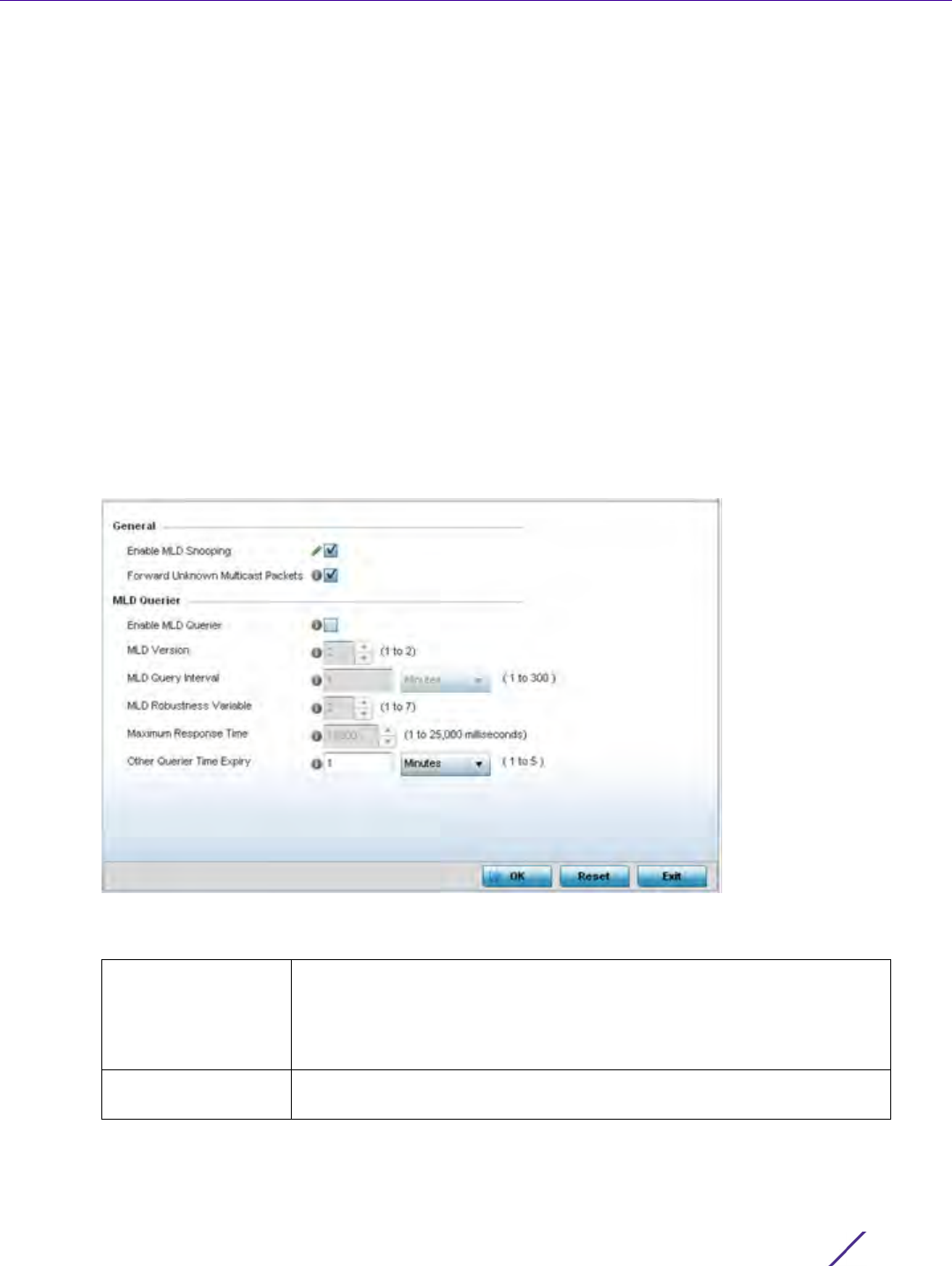
Device Configuration
Wireless Controller and Service Platform System Reference Guide 5 - 134
5.2.8.6 Overriding a Profile’s MLD Snooping Configuration
Overriding a Profile’s Network Configuration
Multicast Listener Discovery (MLD) snooping enables a controller, service platform or Access Point to examine MLD
packets and make forwarding decisions based on content. MLD is used by IPv6 devices to discover devices
wanting to receive multicast packets destined for specific multicast addresses. MLD uses multicast listener queries
and multicast listener reports to identify which multicast addresses have listeners and join multicast groups.
MLD snooping caps the flooding of IPv6 multicast traffic on controller, service platform or Access Point VLANs.
When enabled, MLD messages are examined between hosts and multicast routers and to discern which hosts are
receiving multicast group traffic. The controller, service platform or Access Point then forwards multicast traffic
only to those interfaces connected to interested receivers instead of flooding traffic to all interfaces.
To set an IPv6 MLD snooping configuration for the profile:
1Select
Configuration > Profiles > Network.
2 Expand the Network menu to display its submenu options.
3Select
MLD Snooping.
Figure 5-72 Profile - Network MLD Snooping screen
4 Define the following General MLD snooping settings:
Enable MLD
Snooping
Enable MLD snooping to examine MLD packets and make content
forwarding for this profile. Packets delivered to group members are
identified by a single multicast group address. Multicast packets are
delivered to a group using best-effort reliability, just like IPv6 unicast. MLD
snooping is disabled by default.
Forward Unknown
Multicast Packets
Use this option to either enable or disable IPv6 unknown multicast
forwarding. This setting is enabled by default.

Device Configuration
Wireless Controller and Service Platform System Reference Guide 5 - 135
5 Define the following MLD Querier settings for the MLD snooping configuration:
6 Select the OK button located to save the changes. Select Reset to revert to the last saved configuration.
5.2.8.7 Overriding a Profile’s Quality of Service (QoS) Configuration
Overriding a Profile’s Network Configuration
The controller or service platform use different Quality of Service (QoS) screens to define WLAN and device radio
QoS and traffic shaping configurations for profiles.
Traffic shaping regulates network data transfers to ensure a specific performance level. Traffic shaping delays the
flow of packets defined as less important than prioritized traffic streams. Traffic shaping enables traffic control out
an interface to match its flow to the speed of a remote target’s interface and ensure traffic conforms applied
policies. Traffic can be shaped to meet downstream requirements and eliminate network congestion when data
rates are in conflict.
QoS values are required to provide priority of service to some packets over others. For example, VoIP packets get
higher priority than data packets to provide a better quality of service for high priority voice traffic.
The profile QoS screen maps the 6-bit Differentiated Service Code Point (DSCP) code points to the older 3-bit IP
Precedent field located in the Type of Service byte of an IP header. DSCP is a protocol for specifying and
controlling network traffic by class so that certain traffic types get precedence. DSCP specifies a specific per-hop
behavior that is applied to a packet. This QoS assignment can be overridden as needed, but removes the device
configuration from the profile that may be shared with other similar device models.
To define an QoS configuration:
Enable MLD Querier Select the option to enable MLD querier on the controller, service platform
or Access Point. When enabled, the device sends query messages to
discover which network devices are members of a given multicast group.
This setting is disabled by default.
MLD Version Define whether MLD version 1 or 2 is utilized as the MLD querier. MLD
version 1 is based on IGMP version 2 for IPv4. MLD version 2 is based on
IGMP version 3 for IPv4 and is fully backward compatible. IPv6 multicast
uses MLD version 2. The default MLD version is 2.
MLD Query Interval Set the interval in which query messages are sent to discover device
multicast group memberships. Set an interval in either Seconds (1 -
18,000), Minutes (1 - 300) or Hours (1 - 5). The default interval is 1 minute.
MLD Robustness
Variable
Set a MLD IGMP robustness value (1 - 7) used by the sender of a query.
The MLD robustness variable enables refinements to account for expected
packet loss on a subnet. Increasing the robust count allows for more
packet loss, but increases the leave latency of the subnetwork unless the
value is zero. The default variable is 2.
Maximum Response
Time
Specify the maximum response time (from 1 - 25,000 milliseconds) before
sending a responding report. Queriers use MLD reports to join and leave
multicast groups and receive group traffic. The default setting is 10
milliseconds.
Other Querier time
Expiry
Specify an interval in either Seconds (60 - 300) or Minutes
(1 - 5) used as a timeout interval for other querier resources. The default
setting is 1 minute.
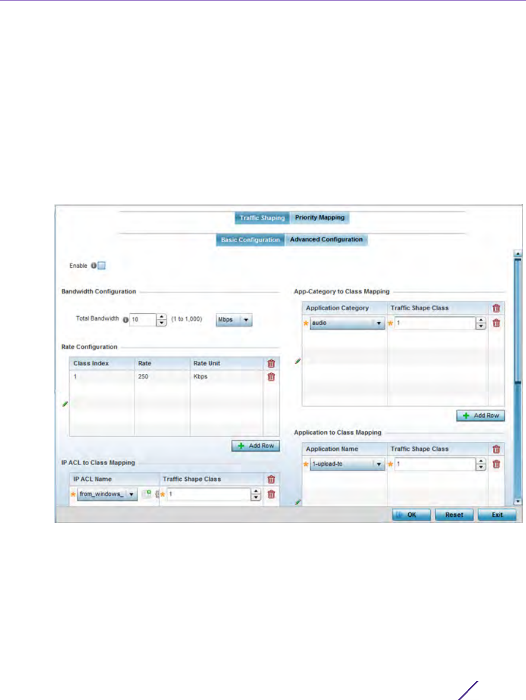
Device Configuration
Wireless Controller and Service Platform System Reference Guide 5 - 136
1Select
Devices from the Configuration tab.
The Device Configuration screen displays a list of managed devices or peer controllers, service platforms or
Access Points.
2 Select a target device (by double-clicking it) from amongst those displayed within the Device Configuration
screen.
Devices can also be selected directly from the Device Browser in the lower, left-hand, side of the UI.
3Select
Profile Overrides from the Device menu to expand it into sub menu options.
4Select
Network to expand its sub menu options.
5Select
Quality of Service.
The Traffic Shaping screen displays with the Basic Configuration tab displayed by default.
Figure 5-73 Profile Overrides - Network QoS Traffic Shaping Basic Configuration screen
Apply traffic shaping to specific applications to apply application categories. When application and ACL rules
are conflicting, applications have priority, followed by application categories, then ACLs.
6Select
Enable to provide traffic shaping using the defined bandwidth, rate and class mappings.
7Set the Total Bandwidth configurable for the traffic shaper. Set the value from either 1 - 1,000 Mbps, or from
250 - 1,000,000 Kbps.
8Select
+ Add Row within the Rate Configuration table to set the Class Index and Rate (in either Kbps, Mbps or
percentage) for the traffic shaper class. Use the rate configuration to control the maximum traffic rate sent or
received on the device. Consider this form of rate limiting on interfaces at the edge of a network to limit traffic
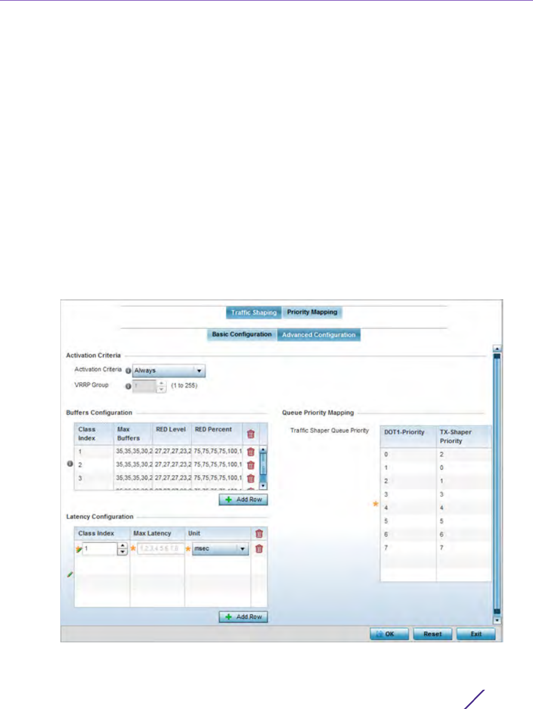
Device Configuration
Wireless Controller and Service Platform System Reference Guide 5 - 137
into or out of the network. Traffic within the set limit is sent and traffic exceeding the set limit is dropped or
sent with a different priority.
9 Refer to the IP ACL Class Mapping table and select + Add Row to apply an IPv4 formatted ACL to the shaper
class mapping. Select + Add Row to add mappings. For more information on creating IP based firewall rules,
refer to Configuring IP Firewall Rules on page 10-20 and Setting an IPv4 or IPv6 Firewall Policy on page 10-21.
10 Refer to the IPv6 ACL Class Mapping table and select + Add Row to apply an IPv6 formatted ACL to the shaper
class mapping. Select + Add Row to add mappings. For more information on creating IP based firewall rules,
refer to Configuring IP Firewall Rules on page 10-20 and Setting an IPv4 or IPv6 Firewall Policy on page 10-21.
11 Refer to the App-Category to Class Mapping table and select + Add Row to apply an application category to
shaper class mapping. Select + Add Row to add mappings by selecting the application category and its traffic
shaper class. For more information on creating an application category, refer to Application on page 7-58.
12 Refer to the Application to Class Mapping table and select + Add Row to apply an application to shaper class
mapping. Select + Add Row to add mappings by selecting the application and its traffic shaper class. For more
information on creating an application, refer to Application on page 7-58.
13 Select the OK button located to save the changes to the traffic shaping basic configuration. Select Reset to
revert to the last saved configuration.
14 Select the Advanced Configuration tab.
Figure 5-74 Profile Overrides - Network QoS Traffic Shaping Advanced Configuration screen

Device Configuration
Wireless Controller and Service Platform System Reference Guide 5 - 138
15 Set the following Activation Criteria for traffic shaper activation:
16 Select + Add Row within the Buffers Configuration table to set the following:
17 Select + Add Row within the Latency Configuration table to set the Class Index (1 - 4), Max Latency and latency
measurement Unit. Max latency specifies the time limit after which packets start dropping (maximum packet
delay in the queue). The maximum number of entries is 8. Select whether msec (default) or usec is unit for
latency measurement.
When a new packet arrives it knows how much time to wait in the queue. If a packet takes longer than the
latency value it’s dropped. By default latency is not set, so packets remain in queue for long time.
18 Refer to the Que Priority Mapping table to set the traffic shaper queue priority and specify a particular queue
inside a class. There are 8 queues (0 - 7), and traffic is queued in each based on incoming packets mark 802.1p
markings.
19 Select the OK button located to save the changes to the traffic shaping advanced configuration. Select Reset to
revert to the last saved configuration.
Activation Criteria Use the drop-down menu to determine when the traffic shaper is
invoked. Options include vrrp-master, cluster-master, rf-domain-manager
and Always. A VRRP master responds to ARP requests, forwards packets
with a destination link MAC layer address equal to the virtual router MAC
layer address, rejects packets addressed to the IP associated with the
virtual router and accepts packets addressed to the IP associated with the
virtual router. The solitary cluster master is the cluster member elected,
using a priority assignment scheme, to provide management
configuration and Smart RF data to other cluster members. Cluster
requests go through the elected master before dissemination to other
cluster members. The RF Domain manager is the elected member
capable of storing and provisioning configuration and firmware images
for other members of the RF Domain.
VRRP Group Set the VRRP group ID from 1 - 255. VRRP groups is only enabled when
the Establishment Criteria is set to vrrp-master.
Class Index Set a class index from 1 - 4.
Max Buffers Se the Max Buffers to specify the queue length limit after which the
queue starts to drop packets. Set the maximum queue lengths for
packets. The upper length is 400 for Access Points.
RED Level Set the packet queue length for RED. The upper limit is 400 for Access
Points. The rate limiter uses the random early detection (RED) algorithm
for rate limiting traffic. RED is a queueing technique for congestion
avoidance. RED monitors the average queue size and drops or marks
packets. If the buffer is near empty, all incoming packets are accepted.
When the queue grows, the probability for dropping an incoming packet
also grows. When the buffer is full, the probability has reached 1 and all
incoming packets are dropped.
RED Percent Set a percentage (1 - 100) for RED rate limiting at a percentage of
maximum buffers.
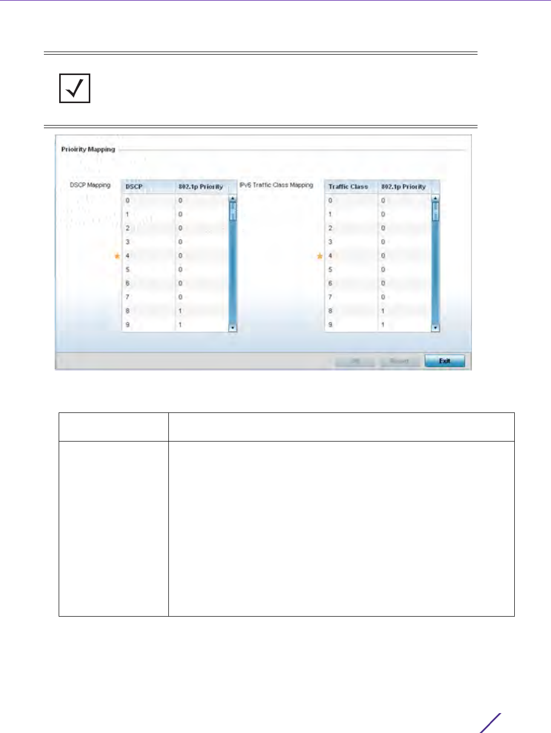
Device Configuration
Wireless Controller and Service Platform System Reference Guide 5 - 139
20 Select the Priority Mapping tab.
Figure 5-75 Profile Overrides - Network QoS screen
21 Set or override the following parameters for IP DSCP Mappings for untagged frames:
NOTE: A blue override icon (to the left of a parameter) defines the parameter as
having an override applied. To remove an override go to the Basic Configuration
section of the device and click the Clear Overrides button. This removes all
overrides from the device.
DSCP Lists the DSCP value as a 6-bit parameter in the header of every IP packet
used for packet classification.
802.1p Priority Assign a 802.1p priority as a 3-bit IP precedence value in the Type of
Service field of the IP header used to set the priority. The valid values for
this field are 0-7. Up to 64 entries are permitted. The priority values are:
0 – Best Effort
1 – Background
2 – Spare
3 – Excellent Effort
4 – Controlled Load
5 – Video
6 – Voice
7 – Network Control

Device Configuration
Wireless Controller and Service Platform System Reference Guide 5 - 140
22 Set or override the following parameters for IPv6 Traffic Class Mapping for untagged frames:
23 Use the spinner controls within the 802.1p Priority field for each DSCP row to change or override the assigned
priority value.
24 Select the OK button located to save the changes and overrides. Select Reset to revert to the last saved
configuration.
5.2.8.8 Overriding a Profile’s Spanning Tree Configuration
Overriding a Profile’s Network Configuration
The Multiple Spanning Tree Protocol (MSTP) provides an extension to RSTP to optimize the usefulness of VLANs.
MSTP allows for a separate spanning tree for each VLAN group, and blocks all but one of the possible alternate
paths within each spanning tree topology.
If there’s just one VLAN in the Access Point managed network, a single spanning tree works fine. However, if the
network contains more than one VLAN, the network topology defined by single STP would work, but it’s possible
to make better use of the alternate paths available by using an alternate spanning tree for different VLANs or
groups of VLANs.
A MSTP supported deployment uses multiple MST regions with multiple MST instances (MSTI). Multiple regions and
other STP bridges are interconnected using one single common spanning tree (CST).
MSTP includes all of its spanning tree information in a single Bridge Protocol Data Unit (BPDU) format. BPDUs are
used to exchange information bridge IDs and root path costs. Not only does this reduce the number of BPDUs
required to communicate spanning tree information for each VLAN, but it also ensures backward compatibility
with RSTP. MSTP encodes additional region information after the standard RSTP BPDU as well as a number of
MSTI messages. Each MSTI messages conveys spanning tree information for each instance. Each instance can be
assigned a number of configured VLANs. The frames assigned to these VLANs operate in this spanning tree
instance whenever they are inside the MST region. To avoid conveying their entire VLAN to spanning tree mapping
in each BPDU, the Access Point encodes an MD5 digest of their VLAN to an instance table in the MSTP BPDU. This
digest is used by other MSTP supported devices to determine if the neighboring device is in the same MST region
as itself.
Traffic Class Devices that originate a packet must identify different classes or priorities
for IPv6 packets. Devices use the traffic class field in the IPv6 header to
set this priority.
802.1p Priority Assign a 802.1p priority as a 3-bit IPv6 precedence value in the Type of
Service field of the IPv6 header used to set the priority. The valid values
for this field are 0-7. Up to 64 entries are permitted. The priority values
are:
0 – Best Effort
1 – Background
2 – Spare
3 – Excellent Effort
4 – Controlled Load
5 – Video
6 – Voice
7 – Network Control
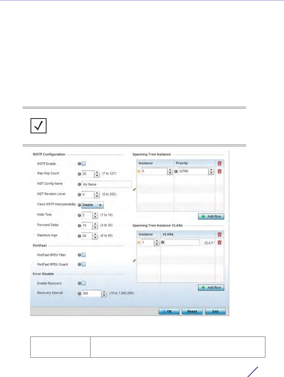
Device Configuration
Wireless Controller and Service Platform System Reference Guide 5 - 141
To create or override a profile’s spanning tree configuration:
1Select
Devices from the Configuration tab.
The Device Configuration screen displays a list of managed devices or peer controllers, service platforms or
Access Points.
2 Select a target device (by double-clicking it) from amongst those displayed within the Device Configuration
screen.
Devices can also be selected directly from the Device Browser in the lower, left-hand, side of the UI.
3Select
Profile Overrides from the Device menu to expand it into sub menu options.
4Select
Network to expand its sub menu options.
5Select
Spanning Tree.
Figure 5-76 Spanning Tree screen
6 Set the following MSTP Configuration parameters:
NOTE: A blue override icon (to the left of a parameter) defines the parameter as
having an override applied. To remove an override go to the Basic Configuration
section of the device and click the Clear Overrides button. This removes all
overrides from the device.
MSTP Enable Select this option to enable MSTP for this profile. MSTP is disabled by
default, so if requiring different (groups) of VLANs with the profile
supported network segment.

Device Configuration
Wireless Controller and Service Platform System Reference Guide 5 - 142
7 Set the following PortFast parameters for the profile configuration:
8 Set the following Error Disable parameters for the profile configuration:
9Use the Spanning Tree Instance table to add indexes to the spanning tree topology.
Max Hop Count Define the maximum number of hops the BPDU will consider valid in the
spanning tree topology. The available range is from 7 -127. The default
setting is 20.
MST Config Name Define a 64 character maximum name for the MST region as an
identifier.
MST Revision Level Set a numeric revision value ID for MST configuration information. Set a
value from 0 - 255. The default setting is 0.
Cisco MSTP
Interoperability
Select either the Enable or Disable radio buttons to enable/disable
interoperability with Cisco’s version of MSTP, which is incompatible with
standard MSTP. This setting is disabled by default.
Hello Time Set a BPDU hello interval from 1 - 10 seconds. BPDUs are exchanged
regularly (every 2 seconds by default) and enable supported devices to
keep track of network changes and star/stop port forwarding as
required.
Forward Delay Set the forward delay time from 4 - 30 seconds. When a device is first
attached to a port, it does not immediately forward data. It first
processes BPDUs and determines the network topology. When a host is
attached the port always goes into the forwarding state, after a delay of
while it goes through the listening and learning states. The time spent in
listening and learning states is set by the forward delay (15 seconds by
default).
Maximum Age Use the spinner control to set the maximum time (in seconds) to listen
for the root bridge. The root bridge is the spanning tree bridge with the
smallest (lowest) bridge ID. Each bridge has a unique ID and a
configurable priority number, the bridge ID contains both. The available
range is from 6 - 40 seconds. The default setting is 20 seconds.
PortFast BPDU Filter Select Enable to invoke a BPDU filter for this portfast enabled port.
Enabling the BPDU filter feature ensures this port channel does not
transmit or receive any BPDUs. BPDUs are exchanged regularly and
enable the Access Point to keep track of network changes and to start
and stop port forwarding as required. The default setting is Disabled.
PortFast BPDU Guard Select Enable to invoke a BPDU guard for the portfast enabled port.
Enabling the BPDU Guard feature means this port will shutdown on
receiving a BPDU. Thus, no BPDUs are processed. BPDUs are exchanged
regularly and enable the Access Point to keep track of network changes
and to start and stop port forwarding as required. The default is
Disabled.
Enable Recovery Select this option to enable a error disable timeout resulting from a
BPDU guard. This setting is disabled by default.
Recovery Interval Define the recovery interval used to enable disabled ports. The available
range is from 10 - 1,000,000 seconds with a default setting of 300.

Device Configuration
Wireless Controller and Service Platform System Reference Guide 5 - 143
10 Add up to 16 indexes and use the Priority setting to define the bridge priority used to determine the root
bridge. The lower the setting defined, the greater the likelihood of becoming the root bridge in the spanning
tree topology.
11 Use the Spanning Tree Instance VLANs table to add up to 15 VLAN instance indexes (by numeric ID) and VLANs
to the spanning tree topology as virtual route resources.
12 Select the OK button located at the bottom right of the screen to save the changes and overrides. Select Reset
to revert to the last saved configuration.
5.2.8.9 Overriding a Profile’s Routing Configuration
Overriding a Profile’s Network Configuration
Routing is the process of selecting IP paths within the wireless network to route traffic. Use the Routing screen to
set Destination IP and Gateway addresses enabling the assignment of static IP addresses for requesting clients
without creating numerous host pools with manual bindings. This eliminates the need for a long configuration file
and reduces the resource space required to maintain address pools.
Both IPv4 and IPv6 routes are separately configurable using their appropriate tabs. For IPv6 networks, routing is
the part of IPv6 that provides forwarding between hosts located on separate segments within a larger IPv6
network where IPv6 routers provide packet forwarding for other IPv6 hosts.
To create or override a profile’s static routes:
1Select
Devices from the Configuration tab.
The Device Configuration screen displays a list of managed devices or peer controllers, service platforms or
Access Points.
2 Select a target device (by double-clicking it) from amongst those displayed within the Device Configuration
screen.
Devices can also be selected directly from the Device Browser in the lower, left-hand, side of the UI.
3Select
Profile Overrides from the Device menu to expand it into sub menu options.
4Select
Network to expand its sub menu options.
5Select
Routing. The IPv4 Routing tab displays by default.
NOTE: A blue override icon (to the left of a parameter) defines the parameter as
having an override applied. To remove an override go to the Basic Configuration
section of the device and click the Clear Overrides button. This removes all
overrides from the device.
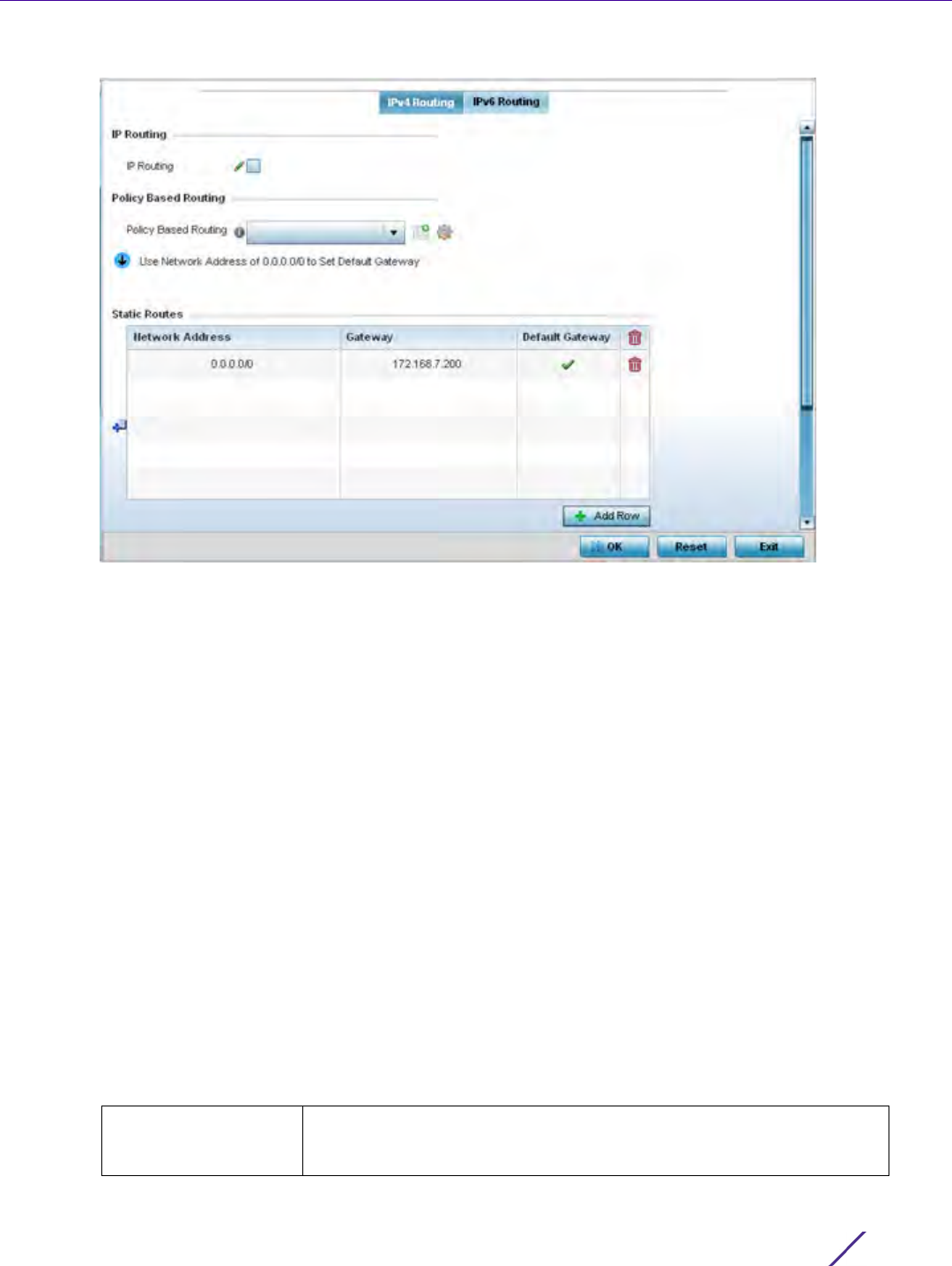
Device Configuration
Wireless Controller and Service Platform System Reference Guide 5 - 144
Figure 5-77 IPv4 Static Routes screen
6Select IP Routing to enable static routes using IP addresses. This sets Destination IP and Gateway addresses
enabling the assignment of static IP addresses for requesting clients. This option is enabled by default.
7 Use the drop-down menu to select a Policy Based Routing policy. If a suitable policy is not available, select the
Create icon or modify an existing policy-based routing policy by selecting the Edit icon.
Policy-based routing (PBR) is a means of expressing and forwarding (routing) data packets based on policies
defined by administrators. PBR provides a flexible mechanism for routing packets through routers,
complementing existing routing protocols. PBR is applied to incoming packets. Packets received on an
interface with PBR enabled are considered are passed through enhanced packet filters (route maps). Based on
the route maps, packets are forwarded/routed to their next hop.
Refer to the Static Routes table to set Destination IP and Gateway addresses enabling the assignment of static
IP addresses to requesting clients (without creating numerous host pools with manual bindings).
• Add IP addresses and network masks in the Network Address column.
•Provide the Gateway address used to route traffic.
• Provide an IP address for the Default Gateway used to route traffic.
Note, when routing packets, the controller, by default, obtains Default Gateway and Name Servers IP addresses
from the DHCP server policy. If manually configuring the Default Gateway for static routing, also configure the
Name Server’s IP address in the controller’s device/profile config contexts. For more information on using the
GUI to configure Name Servers, see Overriding a Profile’s DNS Configuration. If using the CLI, in the device/
profile context, execute the following command: ip name-server <NAME-SERVER-IP-ADDRESS>.
8 Refer to the Default Route Priority field and set the following parameters:
Static Default Route
Priority
Use the spinner control to set the priority value (1 - 8,000) for the
default static route. This is weight (priority) assigned to this route versus
others that have been defined. The default setting is 100.
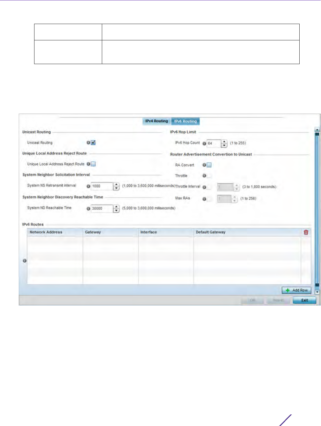
Device Configuration
Wireless Controller and Service Platform System Reference Guide 5 - 145
9 Select the OK button located at the bottom right of the screen to save the changes to IPv4 routing
configuration. Select Reset to revert to the last saved configuration.
10 Select the IPv6 Routing tab. IPv6 networks are connected by IPv6 routers. IPv6 routers pass IPv6 packets from
one network segment to another.
Figure 5-78 Static Routes screen, IPv6 Routing tab
11 Select Unicast Routing to enable IPv6 unicast routing for this profile. Keeping unicast enabled allows the
profile’s neighbor advertisements and solicitations in unicast (as well as multicast) to provide better neighbor
discovery. This setting is enabled by default.
12 Select Unique Local Address Reject Route to reject Unique Local Address (ULA). ULA is an IPv6 address block
(fc00::/7) that is an approximate IPv6 counterpart to IPv4 private addresses. When selected, a reject entry is
added to the IPv6 routing table to reject packets with Unique Local Address.
13 Set a System NS Retransmit Interval (from 1,000 to 3,600,000 milliseconds) as the interval between neighbor
solicitation (NS) messages. NS messages are sent by a node to determine the link layer address of a neighbor,
or verify a neighbor is still reachable via a cached link-layer address. The default is 1,000 milliseconds.
DHCP Client Default
Route Priority
Use the spinner control to set the priority value (1 - 8,000) for the
default route learnt from the DHCP client. The default setting is 1000.
Enable Routing Failure When selected, all default gateways are monitored for activity. The
system will failover to a live gateway if the current gateway becomes
unusable. This feature is enabled by default.
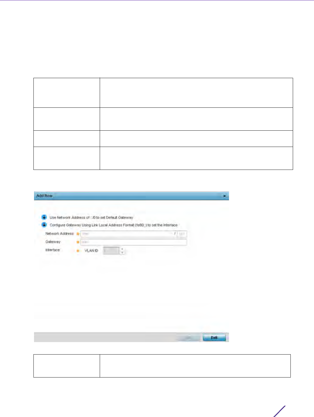
Device Configuration
Wireless Controller and Service Platform System Reference Guide 5 - 146
14 Set a System ND Reachable Time (from 5,000 to 3,600,000 milliseconds) as the time a neighbor is assumed to
be reachable after receiving a receiving a neighbor discovery (ND) confirmation for their reachability. The
default is 30,000 milliseconds.
15 Set an IPv6 Hop Count (from 1 - 255) as the maximum number of hops considered valid when sending IP
packets. The default setting is 64.
16 Set the Router Advertisement Conversion to Unicast settings:
17 Select + Add Row as needed within the IPv6 Routes table to add an additional 256 IPv6 route resources.
Figure 5-79 Static Routes screen, Add IPv6 Route
RA Convert Select this option to convert multicast router advertisements (RA) to
unicast router advertisements at the dot11 layer. Unicast addresses
identify a single network interface, whereas a multicast address is used
by multiple hosts. This setting is disabled by default.
Throttle Select this option to throttle RAs before converting to unicast. Once
enabled, set the throttle interval and maximum number of RAs. This
setting is disabled by default.
Throttle Interval Enable this setting to define the throttle interval (3 - 1,800 seconds). The
default setting is 3 seconds.
Max RAs Enable this setting to define the maximum number of router
advertisements per router (1 - 256) during the throttle interval. The
default setting is 1.
Network Address Set the IPv6 network address. Other than the length and slightly
different look versus an IPv4 address, the IPv6 address concept is same
as IPv4.

Device Configuration
Wireless Controller and Service Platform System Reference Guide 5 - 147
18 Select the OK button located at the bottom right of the screen to save the changes to the IPv6 routing
configuration. Select Reset to revert to the last saved configuration.
5.2.8.10 Overriding a Profile’s Dynamic Routing (OSPF) Configuration
Overriding a Profile’s Network Configuration
Open Shortest Path First (OSPF) is a link-state interior gateway protocol (IGP). OSPF routes IP packets within a
single routing domain (autonomous system), like an enterprise LAN. OSPF gathers link state information from
neighbor routers and constructs a network topology. The topology determines the routing table presented to the
Internet Layer which makes routing decisions based solely on the destination IP address found in IP packets.
OSPF detects changes in the topology, like a link failure, and plots a new loop-free routing structure. It computes
the shortest path for each route using a shortest path first algorithm. Link state data is maintained on each router
and is periodically updated on all OSPF member routers.
OSPF uses a route table managed by the link cost (external metrics) defined for each routing interface. The cost
could be the distance of a router (round-trip time), link throughput or link availability. Setting a cost value provides
a dynamic way to load balancing traffic between routes of equal cost.
An OSPF network can be subdivided into routing areas to simplify administration and optimize traffic utilization.
Areas are logical groupings of hosts and networks, including routers having interfaces connected to an included
network. Each area maintains a separate link state database whose information may be summarized towards the
rest of the network by the connecting router. Areas are identified by 32-bit IDs, expressed either in decimal, or
octet-based dot-decimal notation. Areas can defined as:
stub area - A stub area is an area which does not receive route advertisements external to the autonomous system
(AS) and routing from within the area is based entirely on a default route.
totally-stub - A totally stubby area does not allow summary routes and external routes. A default route is the only
way to route traffic outside of the area. When there’s only one route out of the area, fewer routing decisions are
needed, lowering system resource utilization.
non-stub - A non-stub area imports autonomous system external routes and send them to other areas. However. it
still cannot receive external routes from other areas.
nssa - NSSA is an extension of a stub that allows the injection of limited external routes into a stub area. If
selecting NSSA, no external routes, except a default route, enter the area.
totally nssa - Totally nssa is an NSSA using 3 and 4 summary routes are not flooded into this type of area. It is also
possible to declare an area both totally stubby and not-so-stubby, which means that the area will receive only the
default route from area 0.0.0.0, but can also contain an autonomous system boundary router (ASBR) that accepts
external routing information and injects it into the local area, and from the local area into area 0.0.0.0.
A router running OSPF sends hello packets to discover neighbors and elect a designated router. The hello packet
includes link state information and list of neighbors. OSPF is savvy with layer 2 topologies. If on a point-to-point
Gateway Set the IPv6 route gateway. A network gateway in IPv6 is the same as
in IPv4. A gateway address designates how traffic is routed out of the
current subnet.
Interface If using a link local address, set the VLAN (1 - 4,094) used a virtual
routing interface for the local address.
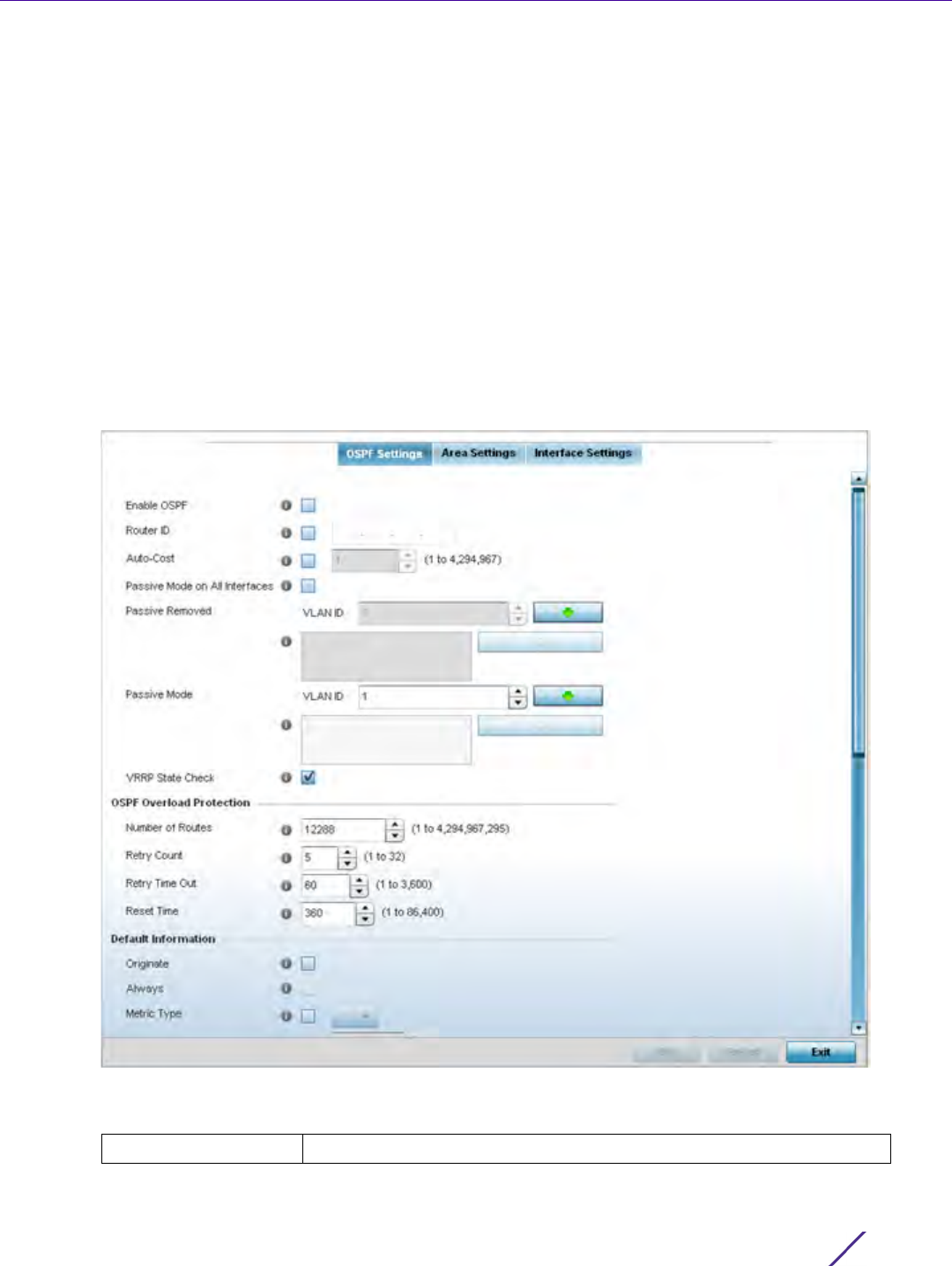
Device Configuration
Wireless Controller and Service Platform System Reference Guide 5 - 148
link, OSPF knows it is sufficient, and the link stays up. If on a broadcast link, the router waits for election before
determining if the link is functional.
To define a dynamic routing configuration:
1Select
Devices from the Configuration tab.
The Device Configuration screen displays a list of managed devices or peer controllers, service platforms or
Access Points.
2 Select a target device (by double-clicking it) from amongst those displayed within the Device Configuration
screen.
Devices can also be selected directly from the Device Browser in the lower, left-hand, side of the UI.
3Select
Profile Overrides from the Device menu to expand it into sub menu options.
4Expand the Network menu and select OSPF.
The OSPF Settings tab displays by default, with additional Area Settings and Interface Settings tabs available.
Figure 5-80 OSPF Settings screen
5 Enable/disable OSPF and provide the following dynamic routing settings:
Enable OSPF Select this option to enable OSPF. OSPF is disabled by default.

Device Configuration
Wireless Controller and Service Platform System Reference Guide 5 - 149
6 Set the following OSPF Overload Protection settings:
7 Set the following Default Information:
Router ID Select this option to define a router ID (numeric IP address) for this
OSPF configuration. This ID must be established in every OSPF instance.
If not explicitly configured, the highest logical IP address is duplicated as
the router identifier. However, since the router identifier is not an IP
address, it does not have to be a part of any routable subnet in the
network.
Auto-Cost Select this option to specify the reference bandwidth (in Mbps) used to
calculate the OSPF interface cost if OSPF is either STUB or NSSA. The
default setting is 1.
Passive Mode on All
Interfaces
When selected, all layer 3 interfaces are set as an OSPF passive
interface. This setting is disabled by default.
Passive Removed If enabling Passive Mode on All Interfaces, use the spinner control to
select VLANs (by numeric ID) as OSPF non passive interfaces. Multiple
VLANs can be added to the list.
Passive Mode If disabling Passive Mode on All Interfaces, use the spinner control to
select VLANs (by numeric ID) as OSPF passive interfaces. Multiple
VLANs can be added to the list.
VRRP State Check Select this option to use OSPF only if the VRRP interface is not in a
backup state. The Virtual Router Redundancy Protocol (VRRP) provides
automatic assignments of available Internet Protocol (IP) routers to
participating hosts. This increases the availability and reliability of
routing paths via automatic default gateway selections on an IP
subnetwork. This setting is enabled by default.
Number of Routes Use the spinner control to set the maximum number of OSPN routes
permitted. The available range is from 1 - 4,294,967,295.
Retry Count Set the maximum number of retries (OSPF resets) permitted before the
OSPF process is shut down. The available range is from 1 - 32. The
default setting is 5.
Retry Time Out Set the duration (in seconds) the OSPF process remains off before
initiating its next retry. The available range is from 1 - 3,600 seconds.
The default is 60 seconds.
Reset Time Set the reset time (in seconds) that, when exceeded, changes the retry
count is zero. The available range is from 1 - 86,400. The default is 360
seconds.
Originate Select this option to make the default route a distributed route. This
setting is disabled by default.
Always Enabling this settings continuously maintains a default route, even when
no routes appear in the routing table. This setting is disabled by default.
Metric Type Select this option to define the exterior metric type (1 or 2) used with
the default route.
Route Metric Select this option to define route metric used with the default route.
OSPF uses path cost as its routing metric. It’s defined by the speed
(bandwidth) of the interface supporting given route.
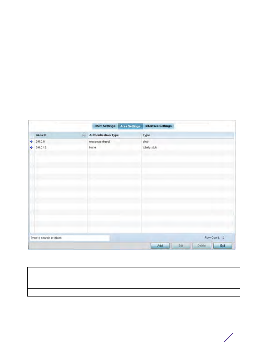
Device Configuration
Wireless Controller and Service Platform System Reference Guide 5 - 150
Refer to the Route Redistribution table to set the types of routes that can be used by OSPF.
Select the + Add Row button to populate the table. Set the Route Type used to define the redistributed route.
Options include connected, kernal and static.
8 Select the Metric Type option to define the exterior metric type (1 or 2) used with the route redistribution.
Select the Metric option to define route metric used with the redistributed route.
9Use the OSPF Network table to define networks (IP addresses) to connect using dynamic routes.
10 Select the + Add Row button to populate the table. Add the IP address and mask of the Network(s)
participating in OSPF. Additionally, define the OSPF area (IP address) to which the network belongs.
11 Set an OSPF Default Route Priority (1 - 8,000) as the priority of the default route learnt from OSPF. The default
setting is 7,000.
12 Select the Area Settings tab.
An OSPF Area contains a set of routers exchanging Link State Advertisements (LSAs) with others in the same
area. Areas limit LSAs and encourage aggregate routes.
Figure 5-81 OSPF Area Settings screen
13 Review existing Area Settings configurations:
14 Select Add to create a new OSPF configuration, Edit to modify an existing configuration or Delete to remove a
configuration.
Area ID Displays either the IP address or integer representing the OSPF area.
Authentication Type Lists the authentication schemes used to validate the credentials of each
dynamic route connection.
Type Lists the OSPF area type for each listed configuration.
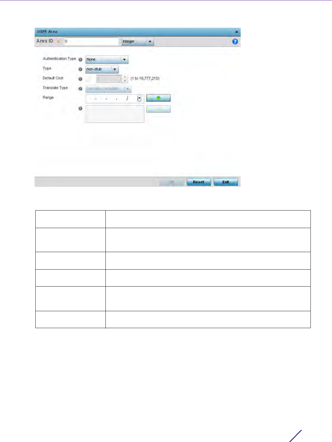
Device Configuration
Wireless Controller and Service Platform System Reference Guide 5 - 151
Figure 5-82 OSPF Area Configuration screen
15 Set the OSPF Area configuration.
16 Select the OK button to save the changes to the area configuration. Select Reset to revert to the last saved
configuration.
17 Select the Interface Settings tab.
Area ID Use the drop down menu and specify either an IP address or integer for
the OSPF area.
Authentication Type Select either None, simple-password or message-digest as credential
validation scheme used with the OSPF dynamic route. The default
setting is None.
Type Set the OSPF area type as either stub, totally-stub, nssa, totally-nssa or
non-stub.
Default Cost Select this option to set the default summary cost advertised if creating
a stub. Set a value from 1 - 16, 777,215.
Translate Type Define how messages are translated. Options include translate-
candidate, translate always and translate-never. The default setting is
translate-candidate.
Range Specify a range of addresses for routes matching address/mask for
OSPF summarization.
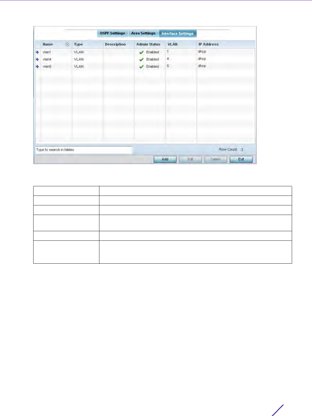
Device Configuration
Wireless Controller and Service Platform System Reference Guide 5 - 152
Figure 5-83 OSPF Interface Settings screen
18 Review the following Interface Settings:
19 Select the Add button to define a new set of virtual interface basic settings, or Edit to update the settings of an
existing virtual interface configuration.
Name Displays the name defined for the interface configuration.
Type Displays the type of interface.
Description Lists each interface’s 32 character maximum description.
Admin Status Displays whether admin status privileges have been enabled or disabled
for the OSPF route’s virtual interface connection.
VLAN Lists the VLAN IDs set for each listed OSPF route virtual interface.
IP Address Displays the IP addresses defined as virtual interfaces for dynamic OSPF
routes. Zero config and DHCP can be used to generate route addresses,
or a primary and secondary address can be manually provided.
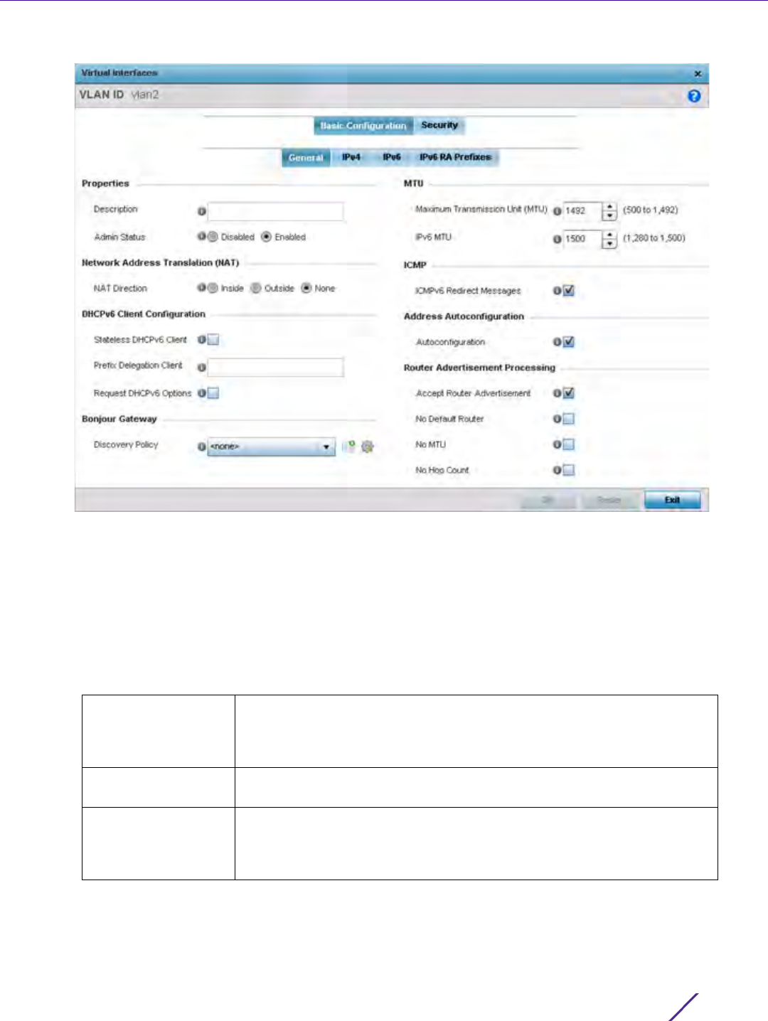
Device Configuration
Wireless Controller and Service Platform System Reference Guide 5 - 153
Figure 5-84 OSPF Virtual Interface - Basic Configuration screen - General tab
20 Within the Properties field, enter a 32 character maximum Description to help differentiate the virtual interface
configuration used with this OSPF route. Enable/disable Admin Status as needed. They’re enabled by default.
21 Define the NAT Direction as either Inside, Outside or None. Network Address Translation (NAT), is an Internet
standard enabling a local area network (LAN) to use IP addresses for internal traffic (inside) and a second set of
addresses for external (outside) traffic.
22 Set the following DHCPv6 Client Configuration. The Dynamic Host Configuration Protocol for IPv6 (DHCPv6)
provides a framework for passing configuration information.
23 Set the following Bonjour Gateway settings.Bonjour is Apple’s implementation of zero-configuration networking
(Zeroconf). Zeroconf is a group of technologies that include service discovery, address assignment and
hostname resolution. Bonjour locates devices such as printers, other computers and services that these
computers offer over a local network.
Stateless DHCPv6
Client
Select this option to request information from the DHCPv6 server using
stateless DHCPv6. DHCPv6 is a networking protocol for configuring IPv6
hosts with IP addresses, IP prefixes or other configuration attributes
required on an IPv6 network. This setting is disabled by default.
Prefix Delegation
Client
Specify a 32 character maximum request prefix for prefix delegation from
a DHCPv6 server over this virtual interface.
Request DHCPv6
Options
Select this option to request DHCPv6 options on this virtual interface.
DHCPv6 options provide configuration information for a node that must
be booted using the network rather than from locally. This setting is
disabled by default.

Device Configuration
Wireless Controller and Service Platform System Reference Guide 5 - 154
Bonjour provides a general method to discover services on a local area network (LAN). It allows users to set up
a network without any configuration. Services such as printers, scanners and file-sharing servers can be found
using Bonjour. Bonjour only works within a single broadcast domain. However, with special DNS configuration,
it can be extended to find services across broadcast domains.
From the drop-down, select the Bonjour Gateway discover policy. Select the Create icon to define a new
Bonjour Gateway policy configuration or select the Edit icon to modify an existing Bonjour Gateway policy
configuration.
24 Set the following MTU settings for the virtual interface:
25 Within the ICMP field, define whether ICMPv6 redirect messages are sent. Redirect requests data packets be
sent on an alternative route. This setting is enabled by default.
26 Within the Address Autoconfiguration field, define whether to configure IPv6 addresses on this virtual interface
based on the prefixes received in router advertisement messages. This setting is enabled by default.
27 Set the following Router Advertisement Processing settings for the virtual interface. Router advertisements are
periodically sent to hosts or sent in response to solicitation requests. The advertisement includes IPv6 prefixes
and other subnet and host information.
28 Select OK to save the changes. Select Reset to revert to the last saved configuration.
29 Select the IPv4 tab to set IPv4 settings for this virtual interface.
Maximum
Transmission Unit
(MTU)
Set the PPPoE client maximum transmission unit (MTU) from 500 - 1,492.
The MTU is the largest physical packet size in bytes a network can
transmit. Any messages larger than the MTU are divided into smaller
packets before being sent. A PPPoE client should be able to maintain its
point-to-point connection for this defined MTU size. The default MTU is
1,492.
IPv6 MTU Set an IPv6 MTU for this virtual interface from 1,280 - 1,500. A larger MTU
provides greater efficiency because each packet carries more user data
while protocol overheads, such as headers or underlying per-packet
delays, remain fixed; the resulting higher efficiency means a slight
improvement in bulk protocol throughput. A larger MTU results in the
processing of fewer packets for the same amount of data. The default is
1,500.
Accept RA Enable this option to allow router advertisements over this virtual
interface. IPv6 hosts can configure themselves automatically when
connected to an IPv6 network using the neighbor discovery protocol via
ICMPv6)router discovery messages. When first connected to a network, a
host sends a link-local router solicitation multicast request for its
configuration parameters; routers respond to such a request with a router
advertisement packet that contains Internet Layer configuration
parameters.This setting is enabled by default.
No Default Router Select this option to not consider routers present on this interface for
default router selection. This setting is disabled by default.
No MTU Select this option to not use the set MTU value for router advertisements
on this virtual interface. This setting is disabled by default.
No Hop Count Select this option to not use the hop count advertisement setting for
router advertisements on this virtual interface. This setting is disabled by
default.
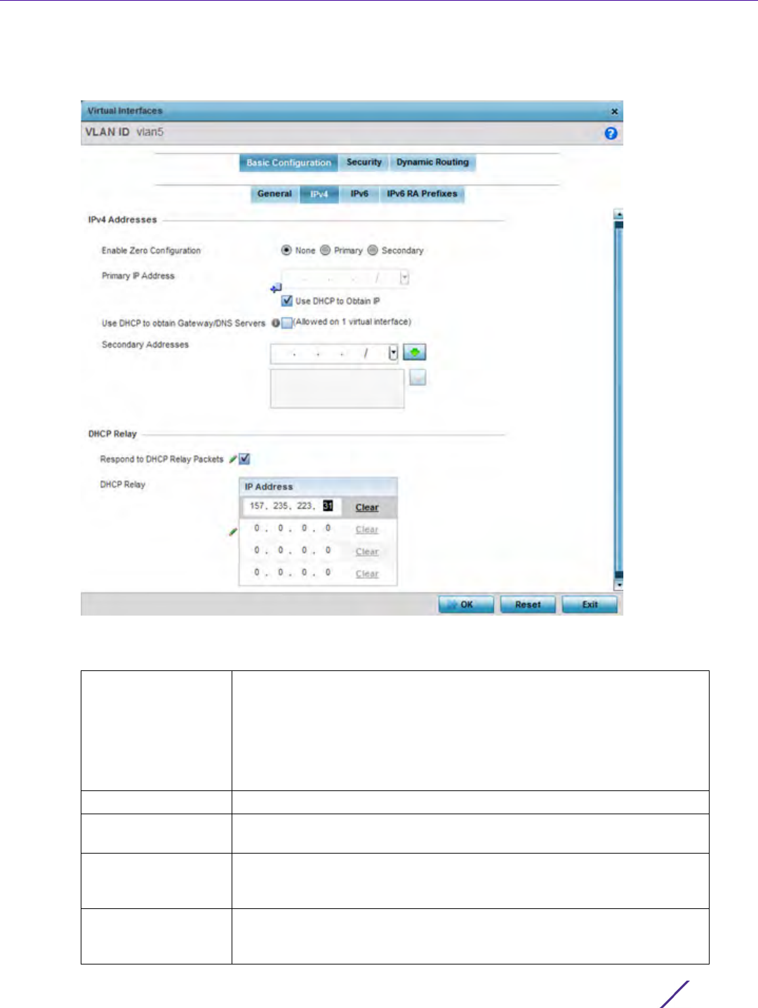
Device Configuration
Wireless Controller and Service Platform System Reference Guide 5 - 155
IPv4 is a connectionless protocol. It operates on a best effort delivery model that does not guarantee delivery
or assures proper sequencing or avoidance of duplicate delivery (unlike TCP).
Figure 5-85 Virtual Interfaces - Basic Configuration screen - IPv4 tab
30 Set the following network information from within the IPv4 Addresses field:
Enable Zero
Configuration
Zero Configuration can be a means of providing a primary or secondary IP
addresses for the virtual interface. Zero configuration (or zero config) is a
wireless connection utility included with Microsoft Windows XP and later
as a service dynamically selecting a network to connect based on a user's
preferences and various default settings. Zero config can be used instead
of a wireless network utility from the manufacturer of a computer's
wireless networking device. This value is set to None by default.
Primary IP Address Define the IP address for the VLAN associated Virtual Interface.
Use DHCP to Obtain
IP
Select this option to allow DHCP to provide the IP address for the Virtual
Interface. Selecting this option disables the Primary IP address field.
Use DHCP to obtain
Gateway/DNS
Servers
Select this option to allow DHCP to obtain a default gateway address, and
DNS resource for one virtual interface. This setting is disabled by default
and only available when the Use DHCP to Obtain IP option is selected.
Secondary Addresses Use the Secondary Addresses parameter to define additional IP addresses
to associate with VLAN IDs. The address provided in this field is used if
the primary IP address is unreachable.
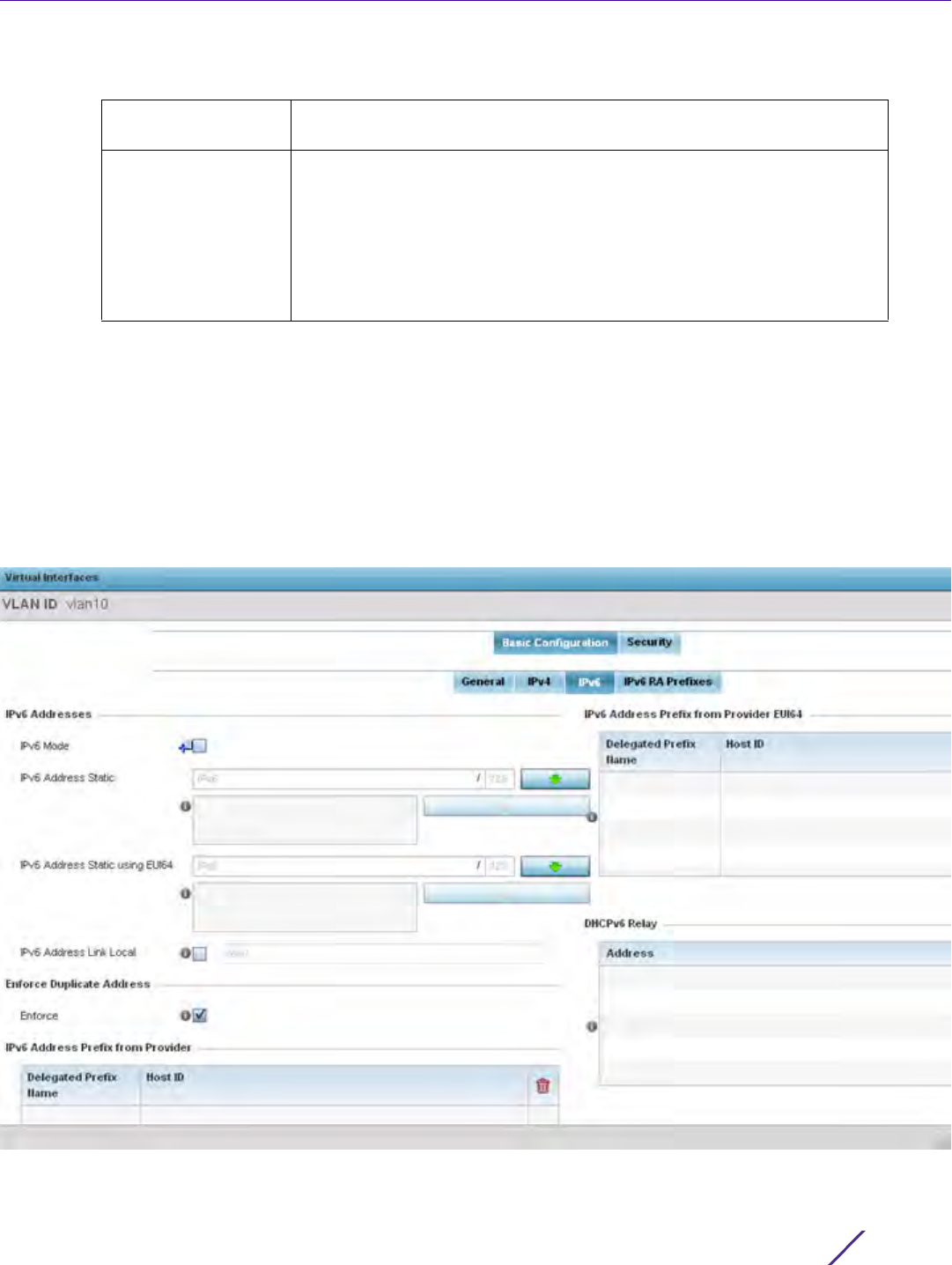
Device Configuration
Wireless Controller and Service Platform System Reference Guide 5 - 156
31 Refer to the DHCP Relay field to set the DHCP relay server configuration used with the Virtual Interface.
32 Select OK to save the changes to the IPv4 configuration. Select Reset to revert to the last saved configuration.
33 Select the IPv6 tab to set IPv6 settings for this virtual interface.
IPv6 is the latest revision of the Internet Protocol (IP) designed to replace IPv4. IPV6 provides enhanced
identification and location information for computers on networks routing traffic across the Internet. IPv6
addresses are composed of eight groups of four hexadecimal digits separated by colons. IPv6 hosts can
configure themselves automatically when connected to an IPv6 network using the neighbor discovery protocol
via ICMPv6 router discovery messages. When first connected to a network, a host sends a link-local router
solicitation multicast request for its configuration parameters; routers respond to such a request with a router
advertisement packet that contains Internet Layer configuration parameters.
Figure 5-86 Virtual Interfaces - Basic Configuration screen - IPv6 tab
Respond to DHCP
Relay Packets
Select this option to allow the onboard DHCP server to respond to relayed
DHCP packets on this interface. This setting is disabled by default.
DHCP Relays Provide IP addresses for DHCP server relay resources. DHCP relays
exchange messages between a DHCPv6 server and client. A client and
relay agent exist on the same link. When a DHCP request is received from
the client, the relay agent creates a relay forward message and sends it to
a specified server address. If no addresses are specified, the relay agent
forwards the message to all DHCP server relay multicast addresses. The
server creates a relay reply and sends it back to the relay agent. The relay
agent then sends back the response to the client.

Device Configuration
Wireless Controller and Service Platform System Reference Guide 5 - 157
34 Refer to the IPv6 Addresses field to define how IP6 addresses are created and utilized.
35 Enable the Enforce Duplicate Address option to enforce duplicate address protection when any wired port is
connected and in a forwarding state. This option is enabled by default.
36 Refer to the IPv6 Address Prefix from Provider table use prefix abbreviations (in EUI64 format) as shortcuts of
the entire character set comprising an IPv6 formatted IP address.
37 Select + Add Row to launch a sub screen wherein a new delegated prefix name and host ID can be defined.
Figure 5-87 Virtual Interfaces - Basic Configuration screen - IPv6 tab - Add Address Prefix from Provider
IPv6 Mode Select this option to enable IPv6 support on this virtual interface.
IPv6 Address Static Define up to 15 global IPv6 IP addresses that can created statically. IPv6
addresses are represented as eight groups of four hexadecimal digits
separated by colons.
IPv6 Address Static
using EU164
Optionally set up to 15 global IPv6 IP addresses (in the EUI-64 format)
that can created statically. The IPv6 EUI-64 format address is obtained
through a 48-bit MAC address. The MAC is initially separated into two 24-
bits, with one being an OUI (Organizationally Unique Identifier) and the
other being client specific. A 16-bit 0xFFFE is then inserted between the
two 24-bits for the 64-bit EUI address. IEEE has chosen FFFE as a
reserved value which can only appear in EUI-64 generated from the an
EUI-48 MAC address.
IPv6 Address Link
Local
Provide the IPv6 local link address. IPv6 requires a link local address
assigned to every interface the IPv6 protocol is enabled, even when one
or more routable addresses are assigned.
Delegated Prefix
Name
Enter a 32 character maximum name for the IPv6 address prefix from
provider.
Host ID Define the subnet ID, host ID and prefix length.
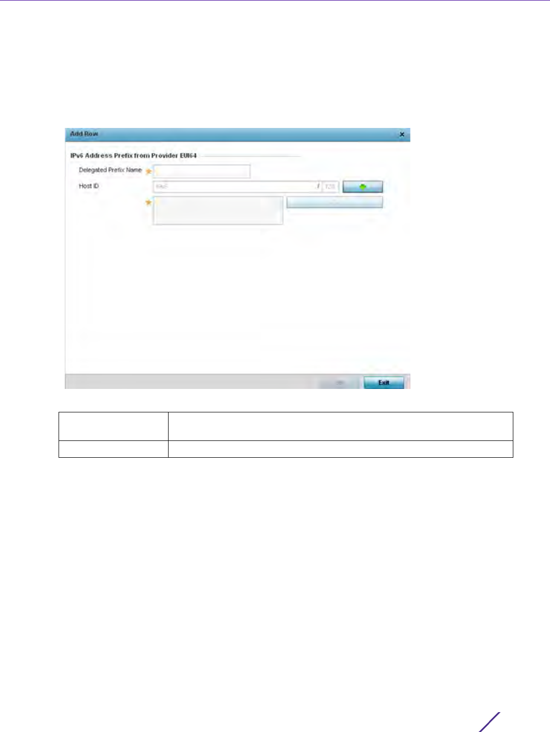
Device Configuration
Wireless Controller and Service Platform System Reference Guide 5 - 158
38 Select OK to save the changes to the new IPv6 prefix from provider. Select Exit to close the screen without
saving the updates.
39 Refer to the IPv6 Address Prefix from Provider EUI64 table to review ISP provided prefix abbreviations.
40 Select + Add Row to launch a sub screen wherein a new delegated prefix name and host ID can be defined in
EUI64 format.
Figure 5-88 Virtual Interfaces - Basic Configuration screen - IPv6 tab - Add Address Prefix from Provider EUI64
41 Select OK to save the changes to the new IPv6 prefix from provider in EUI64 format. Select Exit to close the
screen without saving the updates.
42 Refer to the DHCPv6 Relay table to set the address and interface of the DHCPv6 relay.
The DHCPv6 relay enhances an extended DHCP relay agent by providing support in IPv6. DHCP relays
exchange messages between a DHCPv6 server and client. A client and relay agent exist on the same link.
When A DHCP request is received from the client, the relay agent creates a relay forward message and sends it
to a specified server address. If no addresses are specified, the relay agent forwards the message to all DHCP
server relay multicast addresses. The server creates a relay reply and sends it back to the relay agent. The relay
agent then sends back the response to the client.
43 Select + Add Row to launch a sub screen wherein a new DHCPv6 relay address and interface VLAN ID can be
set.
Delegated Prefix
Name
Enter a 32 character maximum name for the IPv6 address prefix from
provider in EUI format.
Host ID Define the subnet ID and prefix length.

Device Configuration
Wireless Controller and Service Platform System Reference Guide 5 - 159
Figure 5-89 Virtual Interfaces - Basic Configuration screen - IPv6 tab - Add DHCPv6 Relay
44 Select OK to save the changes to the DHCPv6 relay configuration. Select Exit to close the screen without saving
the updates.
45 Select the IPv6 RA Prefixes tab.
Address Enter an address for the DHCPv6 relay. These DHCPv6 relay receive
messages from DHCPv6 clients and forward them to DHCPv6 servers. The
DHCPv6 server sends responses back to the relay, and the relay then
sends these responses to the client on the local network link.
Interface Select this option to enable a spinner control to define a VLAN ID from 1 -
4,094 used as the virtual interface for the DHCPv6 relay. The interface
designation is only required for link local and multicast addresses. A local
link address is a locally derived address designed for addressing on a
single link for automatic address configuration, neighbor discovery or
when no routing resources are available.
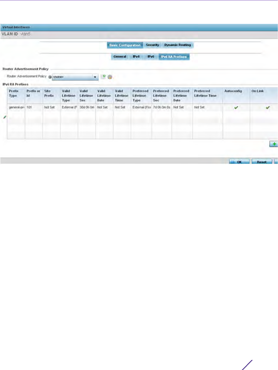
Device Configuration
Wireless Controller and Service Platform System Reference Guide 5 - 160
Figure 5-90 Virtual Interfaces - Basic Configuration screen - IPv6 RA Prefixes tab
46 Use the Router Advertisement Policy drop-down menu to select and apply a policy to the virtual interface.
Router advertisements are periodically sent to hosts or sent in response to solicitation requests. The
advertisement includes IPv6 prefixes and other subnet and host information.
Review the configurations of existing IPv6 advertisement policies. If needed select + Add Row to define the
configuration of an additional IPv6 RA prefix.
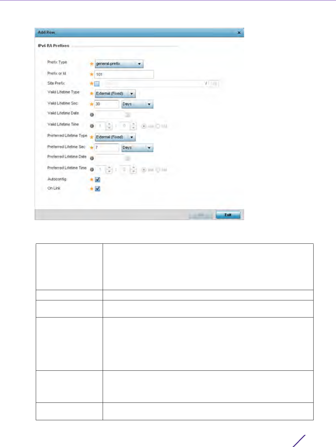
Device Configuration
Wireless Controller and Service Platform System Reference Guide 5 - 161
Figure 5-91 Virtual Interfaces - Basic Configuration screen - Add IPv6 RA Prefix
47 Set the following IPv6 RA Prefix settings:
Prefix Type Set the prefix delegation type used with this configuration. Options
include, Prefix, and prefix-from-provider. The default setting is Prefix. A
prefix allows an administrator to associate a user defined name to an IPv6
prefix. A provider assigned prefix is made available from an Internet
Service Provider (ISP) to automate the process of providing and informing
the prefixes used.
Prefix or ID Set the actual prefix or ID used with the IPv6 router advertisement.
Site Prefix The site prefix is added into a router advertisement prefix. The site
address prefix signifies the address is only on the local link.
Valid Lifetime Type Set the lifetime for the prefix's validity. Options include External (fixed),
decrementing and infinite. If set to External (fixed), just the Valid Lifetime
Sec setting is enabled to define the exact time interval for prefix validity.
If set to decrementing, use the lifetime date and time settings to refine
the prefix expiry period. If the value is set for infinite, no additional date
or time settings are required for the prefix and the prefix will not expire.
The default setting is External (fixed).
Valid Lifetime Sec If the lifetime type is set to External (fixed), set the Seconds, Minutes,
Hours or Days value used to measurement criteria for the prefix's
expiration. 30 days, 0 hours, 0 minutes and 0 seconds is the default
lifetime.
Valid Lifetime Date If the lifetime type is set to External (fixed), set the date in
MM/DD/YYYY format for the expiration of the prefix.
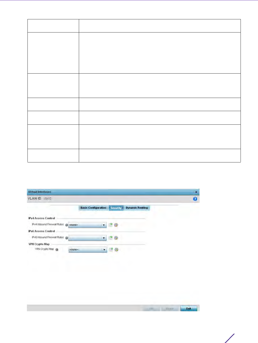
Device Configuration
Wireless Controller and Service Platform System Reference Guide 5 - 162
48 Select OK to save the changes to the IPv6 RA prefix configuration. Select Exit to close the screen without
saving the updates.
49 Select the Security tab.
Figure 5-92 OSPF Virtual Interface - Security screen
Valid Lifetime Time If the lifetime type is set to decrementing, set the time for the prefix's
validity.
Preferred Lifetime
Type
Set the administrator preferred lifetime for the prefix's validity. Options
include External (fixed), decrementing and infinite. If set to External
(fixed), just the Valid Lifetime Sec setting is enabled to define the exact
time interval for prefix validity. If set to decrementing, use the lifetime
date and time settings to refine the prefix expiry period. If the value is set
for infinite, no additional date or time settings are required for the prefix
and the prefix will not expire. The default setting is External (fixed).
Preferred Lifetime
Sec
If the administrator preferred lifetime type is set to External (fixed), set
the Seconds, Minutes, Hours or Days value used to measurement criteria
for the prefix's expiration. 30 days, 0 hours, 0 minutes and 0 seconds is
the default lifetime.
Preferred Lifetime
Date
If the administrator preferred lifetime type is set to External (fixed), set
the date in MM/DD/YYYY format for the expiration of the prefix.
Preferred Lifetime
Time
If the preferred lifetime type is set to decrementing, set the time for the
prefix's validity.
Autoconfig Autoconfiguration entails generating a link-local address, global addresses
via stateless address autoconfiguration and duplicate address detection to
verify the uniqueness of the addresses on a link. This setting is enabled by
default.
On Link Select this option to keep the IPv6 RA prefix on the local link. The default
setting is enabled.

Device Configuration
Wireless Controller and Service Platform System Reference Guide 5 - 163
50 Use the IPv4 Inbound Firewall Rules drop down menu to select the IPv4 specific inbound firewall rules to apply
to this profile’s virtual interface configuration. Select the Create icon to define a new IPv4 firewall rule
configuration or select the Edit icon to modify an existing configuration.
IPv4 is a connectionless protocol for packet switched networking. IPv4 operates as a best effort delivery
method, since it does not guarantee delivery, and does not ensure proper sequencing or duplicate delivery
(unlike (TCP).
IPv4 and IPv6 are different enough to warrant separate protocols. IPv6 devices can alternatively use stateless
address autoconfiguration. IPv4 hosts can use link local addressing to provide local connectivity.
51 Use the IPv6 Inbound Firewall Rules drop down menu to select the IPv6 specific inbound firewall rules to apply
to this profile’s virtual interface configuration. Select the Create icon to define a new IPv6 firewall rule
configuration or select the Edit icon to modify an existing configuration.
IPv6 is the latest revision of the Internet Protocol (IP) replacing IPv4. IPV6 provides enhanced identification and
location information for systems routing traffic across the Internet. IPv6 addresses are composed of eight
groups of four hexadecimal digits separated by colons.
52 Refer to the VPN Crypto Map drop down menu to attach an existing crypto map to this virtual interface. New
crypto map configuration can be added by selecting the Create icon, or existing configurations can be modified
by selecting the Edit icon.
Crypto Map entries are sets of configuration parameters for encrypting packets that pass through the VPN
Tunnel. If a Crypto Map configuration does not exist suiting the needs of this virtual interface, select the Create
icon to define a new Crypto Map configuration or the Edit icon to modify an existing configuration. For more
information, see Overriding a Profile’s VPN Configuration on page 5-207.
53 Use the Web Filter drop-down menu to select or override the URL Filter configuration applied to this virtual
interface. Web filtering is used to restrict access to resources on the Internet.
54 Select OK to save the changes to the configuration. Select Reset to revert to the last saved configuration.
55 Select the Dynamic Routing tab.
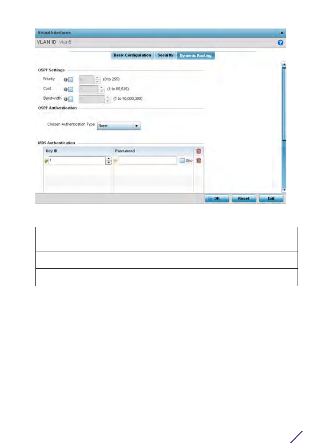
Device Configuration
Wireless Controller and Service Platform System Reference Guide 5 - 164
Figure 5-93 OSPF Virtual Interface - Dynamic Routing screen
56 Define or override the following parameters from within the OSPF Settings field
57 Select the authentication type from the Chosen Authentication Type drop-down used to validate credentials
within the OSPF dynamic route. Options include simple-password, message-digest, null and None. The default is
None.
58 Select the + Add Row button at the bottom of the MD5 Authentication table to add the Key ID and Password
used for an MD5 validation of authenticator credentials. Use the spinner control to set the OSPF message digest
authentication key ID. The available range is from 1 - 255. The password is the OSPF key either displayed as
series or asterisks or in plain text (by selecting Show).
MD5 is a message digest algorithm using a cryptographic hash producing a 128-bit (16-byte) hash value, usually
expressed in text as a 32 digit hexadecimal number. MD5 has been utilized in a wide variety of cryptographic
applications, and is also commonly used to verify data integrity.
59 Select OK to save the changes to the configuration. Select Reset to revert to the last saved configuration.
Priority Select this option to set the OSPF priority used to select the
network designated route. Use the spinner control to set the value
from 0 - 255.
Cost Select this option to set the cost of the OSPF interface. Use the
spinner control to set the value from 1 - 65,535.
Bandwidth Set the OSPF interface bandwidth (in Kbps) from
1 - 10,000,000.

Device Configuration
Wireless Controller and Service Platform System Reference Guide 5 - 165
5.2.8.11 Overriding a Profile’s Border Gateway Protocol (BGP) Configuration
Overriding a Profile’s Network Configuration
Border Gateway Protocol (BGP) is an inter-ISP routing protocol which establishes routing between ISPs. ISPs use
BGP to exchange routing and reachability information between Autonomous Systems (AS) on the Internet. BGP
makes routing decisions based on paths, network policies and/or rules configured by network administrators. The
primary role of a BGP system is to exchange network reachability information with other BGP peers. This
information includes information on AS that the reachability information traverses. This information is sufficient to
create a graph of AS connectivity from which routing decisions can be created and rules enforced.
An Autonomous System (AS) is a set of routers under the same administration that use Interior Gateway Protocol
(IGP) and common metrics to define how to route packets within the AS. AS uses inter-AS routing to route
packets to other ASs. For an external AS, an AS appears to have a single coherent interior routing plan and
presents a consistent picture of the destinations reachable through it.
Routing information exchanged through BGP supports only destination based forwarding (it assumes a router
forwards packets based on the destination address carried in the IP header of the packet).
BGP uses TCP as its transport protocol. This eliminates the need to implement explicit update fragmentation,
retransmission, acknowledgement, and sequencing. BGP listens on TCP port 179. The error notification mechanism
used in BGP assumes that TCP supports a graceful close (all outstanding data is delivered before the connection is
closed).
To define or override a profile’s BGP configuration:
1Select
Devices from the Configuration tab.
The Device Configuration screen displays a list of managed devices or peer controllers, service platforms or
Access Points.
2 Select a target device (by double-clicking it) from amongst those displayed within the Device Configuration
screen.
Devices can also be selected directly from the Device Browser in the lower, left-hand, side of the UI.
3Select
Profile Overrides from the Device menu to expand it into sub menu options.
4Select
Network to expand its sub menu options.
5Select
BGP.
The General tab displays by default.
NOTE: BGP is only supported on RFS4000, RFS6000 and NX9500 model
controllers and service platforms.
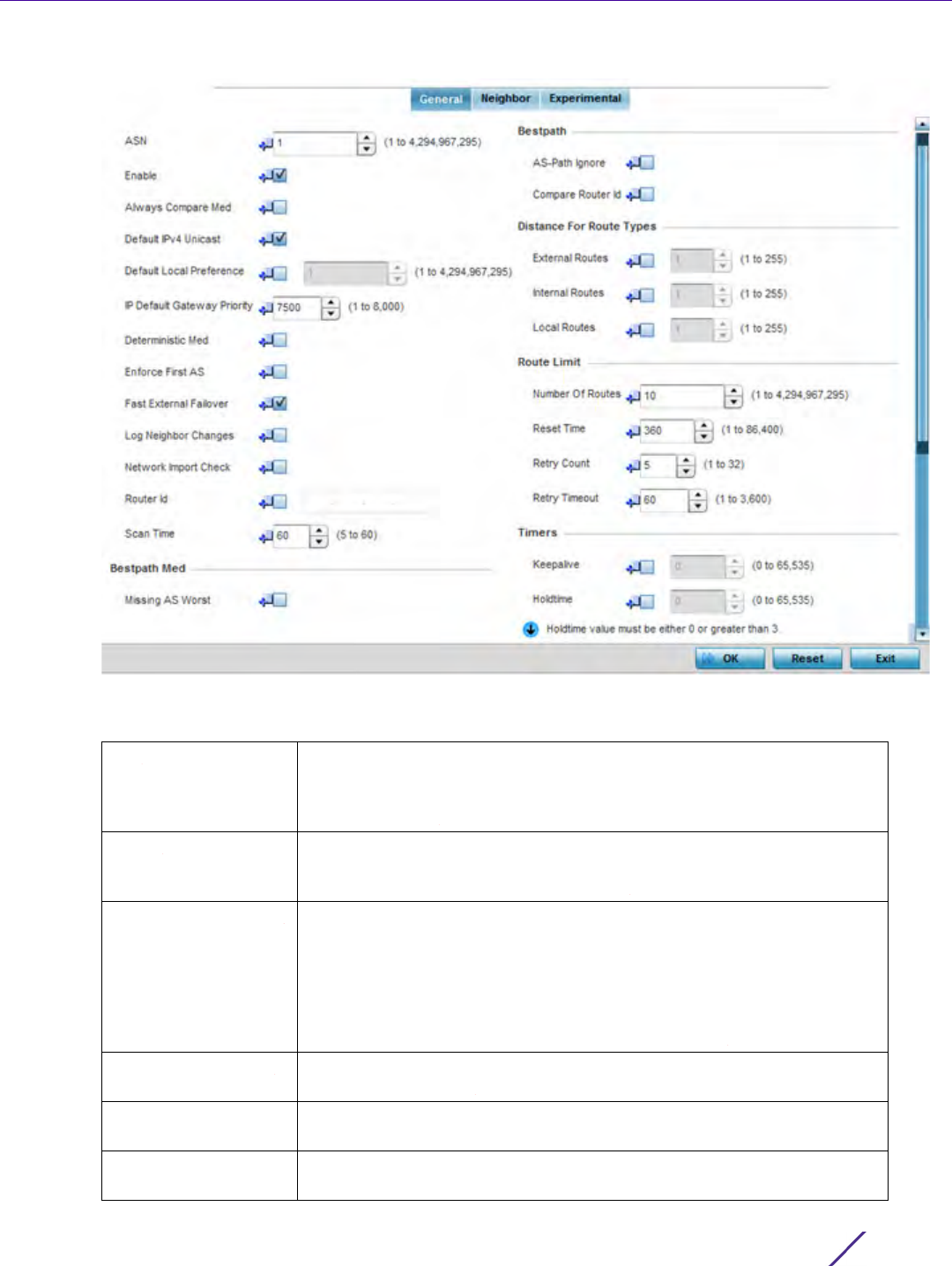
Device Configuration
Wireless Controller and Service Platform System Reference Guide 5 - 166
Figure 5-94 Border Gateway Protocol - General tab
6 Review the following BGP general configuration parameters to determine whether an override is warranted:
ASN Define the Autonomous System Number (ASN). ASN is a set of routers
under the same administration that use Interior Gateway Protocol (IGP)
and common metrics to define how to route packets. Select a value from
1 - 4,294,967,295.
Enable Enable to start BGP on this controller or service platform. BGP is only
supported on RFS4000, RFS6000and NX9500 model controllers and
service platforms. The default is disabled.
Always Compare Med Multi-exit Discriminator (MED) is a value used by BGP peers to select the
best route among multiple routes. When enabled, the MED value
encoded in the route is always compared when selecting the best route
to the host network. A route with a lower MED value is always selected
over a route with a higher MED value. BGP does not discriminate
between iBGP and eBGP when using MED for route selection. This option
is mutually exclusive to the Deterministic MED option.
Default IPv4 Unicast Select this option to enable IPv4 unicast traffic for neighbors. This option
is disabled by default.
Default Local
Preference
Select this option to enable a local preference for the neighbor. When
enabled, set the local preference value (1 - 4,294,967,295).
IP Default Gateway
Priority
Set the default priority value for the IP Default Gateway. Set a value from
1 - 8000. The default is 7500.

Device Configuration
Wireless Controller and Service Platform System Reference Guide 5 - 167
7 Optionally select the Missing AS Worst option to treat any path that does not contain a MED value as the least
preferable route. This setting is disabled by default.
8 Review the following Bestpath parameters:
9 Set or override the following Distance for Route Types. The distance parameter is a rating of route
trustworthiness. The greater the distance, the lower the trust rating. The distance can be set for each type of
route indicating its trust rating.
Deterministic Med Multi-exit Discriminator (MED) is used by BGP peers to select the best
route among multiple routes. When enabled, MED route values (from the
same AS) are compared to select the best route. This best route is then
compared with other routes in the BGP route table to select the best
overall route. This option is mutually exclusive to the Always Compare
MED option.
Enforce First AS Select this option to deny any updates received from an external
neighbor that does not have the neighbor’s configured AS at the
beginning of the received AS path parameter. This enhances security by
not allowing traffic from an unauthorized AS. This setting is disabled by
default.
Fast External Failover Select this option to immediately reset the BGP session on the interface
once the BGP connection goes down. Normally, when a BGP connection
goes down, the device waits for the expiry of the duration specified in
Holdtime parameter before bringing down the interface. This setting is
enabled by default.
Log Neighbor
Changes
Select this option to enable logging of changes in routes to neighbor
BGP peers. This enables the logging of only the changes in neighbor
routes. All other events must be explicitly turned on using debug
commands. This setting is disabled by default.
Network Import
Check
Select this option to enable a network import check to ensure
consistency in advertisements. This setting is disabled by default.
Router ID Select this option to manually configure the router ID for this BGP
supported controller or service platform. The router ID identifies the
device uniquely. When no router ID is specified, the IP address of the
interface is considered the router ID. This setting is disabled by default.
Scan Time Select this option to set the scanning interval for updating BGP routes.
This interval is the period between two consecutive scans the BGP
device checks for the validity of routes in its routing table. To disable this
setting, set the value to Zero (0). The default setting is 60 seconds.
AS-Path Ignore Select this option to prevent an AS path from being considered as a
criteria for selecting a preferred route. The route selection algorithm uses
the AS path as one of the criteria when selecting the best route. When
this option is enabled, the AS path is ignored.
Compare Router Id Select this option to use the router ID as a selection criteria when
determining a preferred route. The route selection algorithm uses various
criteria when selecting the best route. When this option is enabled, the
router ID is used to select the best path between two identical BGP
routes. The route with the lower route ID is selected over a route with a
higher route id.
External Routes External routes are those routes learned from a neighbor of this BGP
device. Set a value from 1 - 255.

Device Configuration
Wireless Controller and Service Platform System Reference Guide 5 - 168
10 Set or override the following Route Limit parameters:
11 Set or override the following Timers:
12 Set the following Aggregate Address parameters:
Aggregate addresses are used to minimize the size of the routing tables. Aggregation combines the attributes
of several different routes and advertises a single route. This creates an aggregation entry in the BGP routing
table if more specific BGP routes are available in the specified address range.
13 Set the following Distance for IP Source Prefix fields:
Internal Routes Internal routes are those routes learned from another router within the
same AS. Set a value from 1 - 255.
Local Routes Local routes are those routes being redistributed from other processes
within this BGP router. Set a value from 1 - 255.
Number of Routes Configures the number of routes that can be stored on this BGP router.
Set this value based on the available memory on this BGP router.
Configure a value from 1 - 4,294,967,295. The default value is 9,216
routes.
Reset Time Configures the reset time. This is the time limit after which the Retry
Count value is set to Zero (0). Set a value from 1- 86,400 seconds.
Retry Count Configures the number of time the BGP process is reset before it is shut
down. Once shut down, the BGP process has to be started manually. The
BGP process is reset if it is flooded with route entries that exceed its
number of routes. Set a value from 1 - 32.
Retry Timeout Configures the time duration in seconds the BGP process is shutdown
temporarily before a reset of the process is attempted. Set a value from 1
- 3,600 seconds.
Keepalive Set the duration, in seconds, for the keep alive timer used to maintain
connections between BGP neighbors. Set a value from 0 - 65,535
seconds.
Holdtime Set the time duration, in seconds, for the hold (delay) of packet
transmissions.
IP Prefix Enter an IP address and mask used as the aggregate address.
Summary Only Select this option to advertise the IP Prefix route to the BGP neighbor
while suppressing the detailed and more specific routes.
As Set Generates AS set path information. Select to enable. When selected, it
creates an aggregate entry advertising the path for this route, consisting
of all elements contained in all the paths being summarized. Use this
parameter to reduce the size of path information by listing the AS
number only once, even if it was included in the multiple paths that were
aggregated.
IP Source Prefix Enter an IP address and mask used as the prefix source address.
Admin Distance Use the spinner control to set the BGP route’s admin distance from 1 -
255.
IP Access List Provide the IP address used to define the prefix list rule.

Device Configuration
Wireless Controller and Service Platform System Reference Guide 5 - 169
14 Configure the following Network values.
15 Configure the following Route Redistribute values.
16 Select OK to save the changes and overrides. Select Reset to revert to the last saved configuration.
17 Select the Neighbor tab.
Figure 5-95 Border Gateway Protocol - Neighbor tab
The Neighbor tab displays a list of configured BGP neighbor devices identified by their IP address.
18 Select Add to add a new BGP neighbor configuration or select an existing Identifier and select Edit to modify it.
The following screen displays with the General tab displayed by default.
Network Configure an IP address to broadcast to neighboring BGP peers. This
network can be a single IP address or a range of IP addresses in A.B.C.D/
M format.
Pathlimit Configure the maximum path limit for this AS. Set a value from 1 - 255
AS hops.
Backdoor Select this option to indicate to border devices this network is reachable
using a backdoor route. A backdoor network is treated the same as a
local network, except it is not advertised. This setting is disabled by
default.
Route Map Select an existing route map as a method of controlling and modifying
routing information. The control of route information occurs using route
redistribution keys.
Route Type Use the drop-down menu to define the route type as either connected,
kernal, ospf or static.
Metric Select this option to set a numeric route metric used for route matching
and permit designations.
Route Map Select an existing route map as a method of controlling and modifying
routing information. The control of route information occurs using route
redistribution keys.
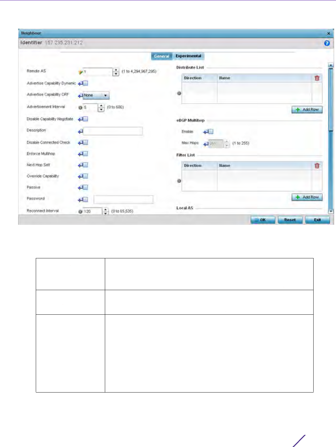
Device Configuration
Wireless Controller and Service Platform System Reference Guide 5 - 170
Figure 5-96 Border Gateway Protocol - Neighbor tab - Add/Edit screen
The General tab displays the different configuration parameters for the neighbor BGP device.
19 Configure the following common parameters:
Remote AS Define the Autonomous System Number (ASN) for the neighbor BGP
device. ASN is a set of routers under the same administration that use
Interior Gateway Protocol (IGP) and common metrics to define how to
route packets within the AS. Set a value from 1 - 4,294,967,295.
Advertise Capability
Dynamic
Select this option to show a neighbor device’s capability to advertise or
withdraw and address capability to other peers in a non-disruptive
manner. This setting is disabled by default.
Advertise Capability
ORF
Select this option to enable Outbound Router Filtering (ORF) and
advertise this capability to peer devices. ORFs send and receive
capabilities to lessen the number of updates exchanged between BGP
peers. By filtering updates, ORF minimizes update generation and
exchange overhead.
The local BGP device advertises ORF in the send mode. The peer BGP
device receives the ORF capability in receive mode. The two devices
exchange updates to maintain the ORF for each router. Only a peer
group or an individual BGP router can be configured to be in receive or
send mode. A member of a peer group cannot be configured.

Device Configuration
Wireless Controller and Service Platform System Reference Guide 5 - 171
Advertisement
Interval
Use the Advertisement Interval to set the minimum interval between
sending BGP router updates. Sending too many router updates creates
flapping of routes leading to possible disruptions. Set a minimum interval
so that the BGP routing updates are sent after the set interval in
seconds. The default is 5 seconds.
Disable Capability
Negotiate
Select to disable capability negotiation with BGP neighbors. This is to
allow compatibility with older BGP versions that have no capability
parameters used in the open messages between peers. This setting id
disabled by default.
Description Provide a 80 character maximum description for this BGP neighbor
device.
Disable Connected
Check
If utilizing loopback interfaces to connect single-hop BGP peers, enable
the neighbor disable connected check before establishing a the BGP
peering session.This setting is disabled by default.
Enforce Multihop A multihop route is a route to external peers on indirectly connected
networks. Select to enforce neighbors to perform multi-hop check. This
setting is disabled by default.
Next Hop Self Select to enable Next Hop Self. Use this to configure this device as the
next hop for a BGP speaking neighbor or peer group. This allows the
BGP device to change the next hop information that is sent to iBGP
peers. The next hop address is set to the IP address of the interface used
to communicate with the eBGP neighbor. This setting is disabled by
default.
Override Capability Select this to enable the ability to override capability negotiation result.
This setting is disabled by default.
Passive Select this option to set this BGP neighbor as passive. When a neighbor
is set as passive, the local device should not attempt to open a
connection to this device. This setting is disabled by default
Reconnect Interval Set a reconnection interval for peer BGP devices from 0 - 65,535
seconds. The default setting is 120 seconds.
Send Community Select this option to ensure the community attribute is sent to the BGP
neighbor. The community attribute groups destinations in a certain
community and applies routing decisions based on the community. On
receiving community attribute, the BGP router announces it to the
neighbor.
Shutdown Select this option to administratively shutdown this BGP neighbor. This
setting is disabled by default.
Soft Reconfiguration
Inbound
Select this option to store updates for inbound soft reconfiguration. Soft-
reconfiguration can be used in lieu of BGP route refresh capability.
Selecting this option enables local storage of all received routes and their
attributes. This requires additional memory on the BGP device.
When a soft reset (inbound) is performed on the neighbor device, the
locally stored routes are reprocessed according to the inbound policy.
The BGP neighbor connection is not affected.

Device Configuration
Wireless Controller and Service Platform System Reference Guide 5 - 172
20 Configure or set the following Default Originate parameters. Default originate is used by the local BGP router to
send the default route 0.0.0.0 to its neighbor for use as a default route.
21 Configure or set the following Route Map parameters. This configures how route maps are applied for this BGP
neighbor.
22 Configure or set the following Distribute List parameters. Up to 2 distribute list entries can be created.
23 Configure or set the following eBGP Multihop parameters. This configures the maximum number of hops that
can be between eBGP neighbors not directly connected to each other.
Update Source Select this option to allow internal BGP sessions to use any operational
interface for TCP connections. Use Update Source in conjunction with
any specified interface on the router. The loopback interface is the
interface that is most commonly used with this command. The use of
loopback interface eliminates a dependency and BGP does not have to
rely on the availability of a particular interface for making TCP
connections. This setting is disabled by default.
Unsuppress Map Enable Unsuppress Map to selectively advertise more precise routing
information to this neighbor. Use this in conjunction with the Route
Aggregate command.
The route aggregate command creates a route map with a IP/mask
address that consolidates the subnets under it. This enables a reduction
in number of route maps on the BGP device to one entry that
encompasses all the different subnets. Use Unsuppress Map to
selectively allow/deny a subnet or a set of subnets.
Use the Create icon to create a new route map. Use the Edit icon to edit
an existing route map list after selecting it.
Weight Select to set the weight of all routes learned from this BGP neighbor.
Weight is used to decide the preferred route when the same route is
learned from multiple neighbors. The highest weight is always chosen.
Enable Select to enable Default Originate on this BGP neighbor. This setting is
disabled by default.
Route Map Use the drop-down menu to select a route map (enhanced packet filter)
to use as the Default Originate route.
Direction Use the drop-down menu to configure the direction on which the
selected route map is applied. Select one from in, out, export or import.
Route Map Use the drop-down menu to select the route map to use with this BGP
neighbor. Use the Create icon to create a new route map. Use the Edit
icon to edit an existing route map after selecting it.
Direction Use the drop-down menu to configure the direction on which the
selected IP access list is applied. Select either in or out.
Name Use the drop-down menu to select the route map to use with this BGP
neighbor. Use the Create icon to create a new IP Access list. Use the Edit
icon to edit an existing IP Access list after selecting it.
Enable Select to enable eBGP Multihop on this BGP neighbor.
Max Hops Set the maximum number of hops between eBGP neighbors not
connected directly. Select a value from 1 - 255.

Device Configuration
Wireless Controller and Service Platform System Reference Guide 5 - 173
24 Configure or set the following Filter List parameters. Up to 2 filter list entries can be created.
25 Configure or set the following Local AS parameters.
26 Configure or set the following Maximum Prefix value. This configures the maximum number of prefix that can
be received from a BGP neighbor.
27 Configure or set the following Prefix List parameters. Up to 2 prefix list entries can be created.
28 Set or override the following Timers for this BGP neighbor:
29 Select OK to save the changes and overrides. Select Reset to revert to the last saved configuration.
Direction Use the drop-down menu to configure the direction on which the
selected AS Path list is applied. Select either in or out.
Name Use the drop-down menu to select the AS Path list to use with this BGP
neighbor. Use the Create icon to create a new AS Path list. Use the Edit
icon to edit an existing AS Path list after selecting it.
CAUTION: This is an experimental feature and its actual operation may be
unpredictable.
AS Number Specify the local Autonomous System (AS) number. Select from 1 -
4,294,967,295.
No Prepend Select to enable. When enabled, the local AS number is not prepended
to route updates from eBGP peers.
Prefix Limit Sets the maximum number of prefix that can be received from a BGP
neighbor. Select from 1 - 4,294,967,295. Once this threshold is reached,
the BGP peer connection is reset.
Threshold Percent Sets the threshold limit for generating a log message. When this percent
of the Prefix Limit is reached, a log entry is generated. For example if the
Prefix Limit is set to 100 and Threshold Percent is set to 65, then after
receiving 65 prefixes, a log entry is created.
Restart Limit Sets the number of times a reset BGP peer connection is restarted.
Select a value from 1 - 65535.
Warning Only Select to enable. When the number of prefixes specified in Prefix Limit
field is exceeded, the connection is reset. However, when this option is
enabled, the connection is not reset and an event is generated instead.
This setting is disabled by default.
Direction Use the drop-down menu to configure the direction on which the
selected IP prefix list is applied. Select either in or out.
Name Use the drop-down menu to select the IP prefix list to use with this BGP
neighbor. Use the Create icon to create a new IP prefix list or select the
Edit icon to edit an existing IP prefix list after selecting it.
Keepalive Set the time duration in seconds for keepalive. The keep alive timer is
used to maintain connections between BGP neighbors. Set a value from 1
- 65,535 seconds.
Holdtime Set the time duration in seconds for the hold time.
!
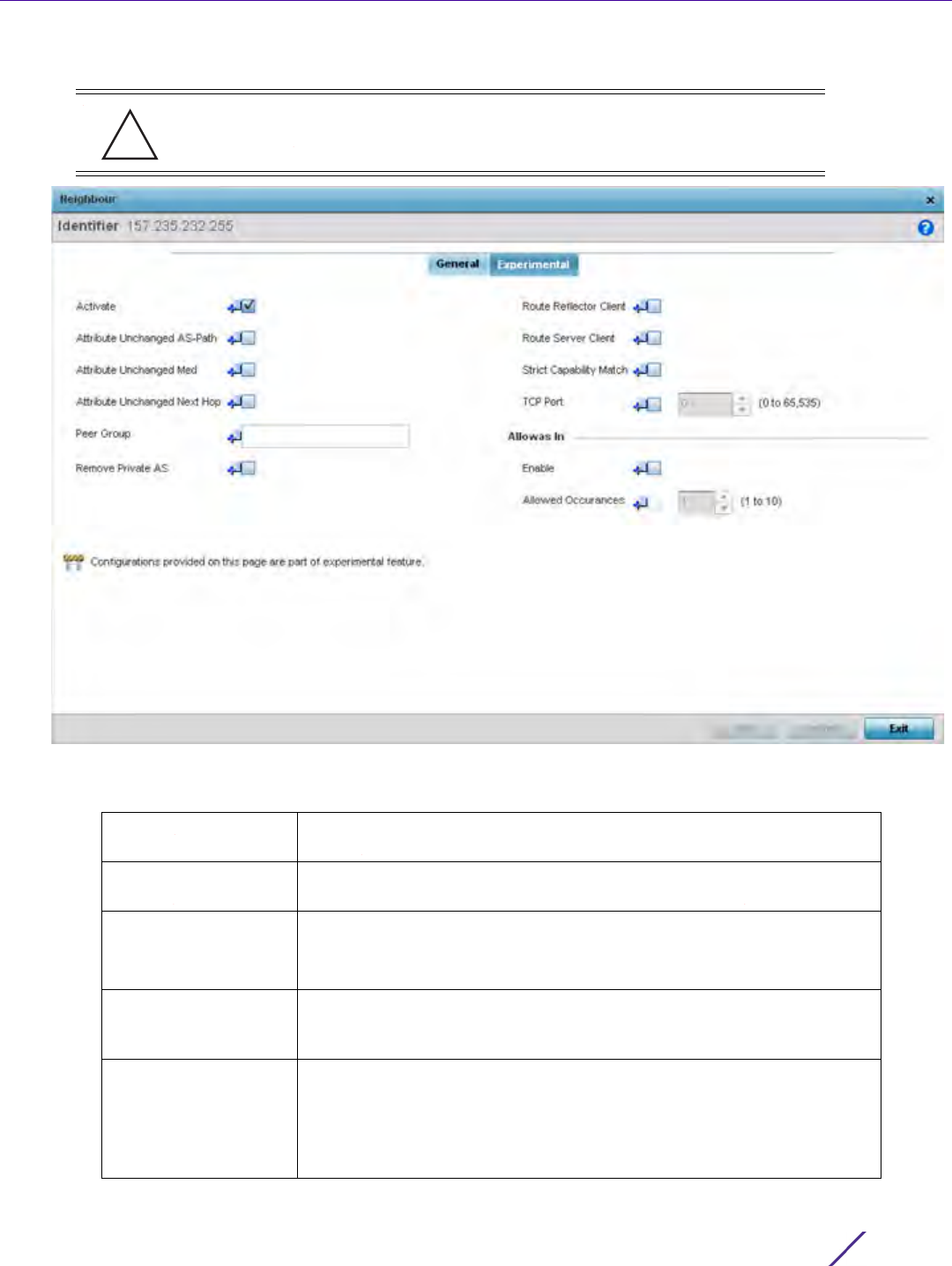
Device Configuration
Wireless Controller and Service Platform System Reference Guide 5 - 174
30 Select the Experimental tab.
Figure 5-97 Border Gateway Protocol - Neighbor tab - Experimental tab
31 Set the following Experimental BGP parameters:
CAUTION: This is an experimental feature and its actual operation may be
unpredictable.
Activate Enable an address family for this neighbor. This setting is enabled by
default.
Attribute Unchanged
AS-Path
Select to enable propagating AS path BGP attribute unchanged to this
neighbor BGP device. This setting is enabled by default.
Attribute Unchanged
Med
Select to enable propagating MED BGP attribute unchanged to this
neighbor BGP device.
This setting is enabled by default.
Attribute Unchanged
Next Hop
Select to enable propagating the next hop BGP attribute value
unchanged to this neighbor BGP device. This setting is enabled by
default.
Peer Group Set the peer group for this BGP neighbor device. Peer groups are a set
of BGP neighbors with the same update policies. This facilitates the
updates of various policies, such as, distribute lists and filter lists.
The peer group can be configured as a single entity. Any changes made
to the peer group is propagated to all members.
!

Device Configuration
Wireless Controller and Service Platform System Reference Guide 5 - 175
32 Configure or set the following Allowas In parameters.
This configures the Provider Edge (PE) routers to allow the re-advertisement of all prefixes containing
duplicate Autonomous System Numbers (ASN). This creates a pair of VPN Routing/Forwarding (VRF)
instances on each PE router to receive and re-advertise prefixes. The PE router receives prefixes with ASNs
from all PE routers and advertises to its neighbor PE routers on one VRF. The other VRF receives prefixes with
ASNs from the Customer Edge (CE) routers and re-advertises them to all PE routers in the configuration.
33 Select OK to save the changes and overrides. Select Reset to revert to the last saved configuration. Select Exit
to close this window and go back to the main screen.
34 Select the Experimental tab from the BGP main screen.
Remove Private AS Select this option to remove the private Autonomous System (AS)
number from outbound updates. Private AS numbers are not advertised
to the Internet. This option is used with external BGP (eBGP) peers only.
The router removes the AS numbers only if the update includes private
AS numbers.
If the update includes both private and public AS numbers, the system
treats it as an error.
Route Reflector Client Select this option to enable this BGP neighbor as a route reflector client
for the local router. Route reflectors control large numbers of iBGP
peering.Using route reflection, the number of iBGP peers is reduced.
This option configures the local BGP device as a route reflector and the
neighbor as its route reflector client. This setting is disabled by default.
Route Server Client Select this option to enable this neighbor BGP device to act as a route
server client. This setting is disabled by default.
Strict Capability
Match
Select this option to enable a strict capability match before allowing a
neighbor BGP peer to open a connection. When capabilities do not
match, the BGP connection is closed. This setting is disabled by default.
TCP Port Select to enable configuration of non-standard BGP port for this BGP
neighbor. By default the BGP port number is 179. To configure a non
standard port for this BGP neighbor, use the control to set the port
number. Select a value from 1 - 65,535.
Enable Select this option to enable re-advertisement of all prefixes containing
duplicate ASNs.
Allowed Occurrences Set the maximum number of times an ASN is advertised. Select a value
in the rage 1 - 10.
CAUTION: This is an experimental feature and its actual operation may be
unpredictable.
!
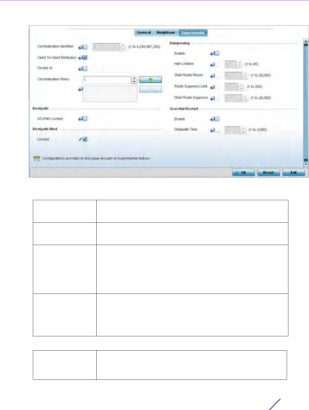
Device Configuration
Wireless Controller and Service Platform System Reference Guide 5 - 176
Figure 5-98 Border Gateway Protocol - Experimental tab
35 Set the following Experimental BGP features:
36 Configure or set the following Bestpath parameter:
Confederation
Identifier
Enable and set a confederation identifier to allow an AS to be divided
into several ASs. This confederation is visible to external routers as a
single AS. Select a value from 1 - 4,294,967,295.
Client to Client
Reflection
Select to enable client-to-client route reflection. Route reflectors are used
when all iBGP speakers are not fully meshed. If the clients are fully
meshed, the route-reflectors are not required. The default is enabled.
Cluster ID Select to enable and set a Cluster ID if the BGP cluster has more than
one route-reflectors. A cluster generally consists of a single route-
reflector and its clients. The cluster is usually identified by the router ID
of this single route-reflector. Sometimes, to increase the redundancy, a
cluster might have more than one route-reflectors configured. In this
case, all route-reflectors in the cluster are identified by the Cluster ID.
Select a value from 1 - 4,294,967,295.
Confederation Peers Use this spinner to select the confederation members. Once selected,
select the Down Arrow button next to this control to add the AS as a
confederation member. Multiple AS configurations can be added to the
list of confederation members. To remove an AS as a confederation
member, select the AS from the list and select the Up Arrow button next
to the list.
AS-Path Confed Select this option to allow the comparison of the confederation AS path
length when selecting the best route. This indicates the AS
confederation path length must be used, if available, in the BGP path
when deciding the best path.

Device Configuration
Wireless Controller and Service Platform System Reference Guide 5 - 177
37 Configure or set the following Bestpath Med parameter:
38 Configure or set the following Dampening parameters.
Dampening minimizes the instability caused by route flapping. A penalty is added for every flap in the flapping
route. As soon as the total penalty reaches the Route Suppress Limit value, the advertisement of this route is
suppressed. This penalty is delayed when the time specified in Half Lifetime occurs. Once the penalty becomes
lower than the value specified in Start Route Reuse, the advertisement of the route is un-suppressed.
39 Configure or set the Graceful Restart parameters. This provides a graceful restart mechanism for a BGP session
reset in which the BGP daemon is not restarted, so that any changes in network configuration that caused the
BGP reset does not affect packet forwarding.
40 Select OK to save the changes and overrides. Select Reset to revert to the last saved configuration. Select Exit
to close this window and go back to the main screen.
5.2.8.12 Overriding a Profile’s Forwarding Database Configuration
Overriding a Profile’s Network Configuration
A Forwarding Database forwards or filter packets on behalf of the managing controller, service platform or Access
Point. The bridge reads the packet’s destination MAC address and decides to either forward the packet or drop
Confed Select to enable. Use this option to allow comparing MED when selecting
the best route when learned from confederation peers. This indicates
that MED must be used, when available, in the BGP best path when
deciding the best path between routes from different confederation
peers.
Enable Select to enable dampening on advertised routes. When this option is
selected, other configuration fields in this Dampening field are enabled.
This setting is disabled by default.
Half Lifetime Select to enable and configure the half lifetime value. A penalty is
imposed on a route that flaps. This is the time for the penalty to
decrease to half its current value. Set a value from 1 - 45 in minutes. The
default is 1 second.
Start Route Reuse Select to enable and configure the route reuse value. When the penalty
for a suppressed route decays below the value specified in Start Route
Reuse field, the route is un-suppressed. Set a value from 1 - 20000.
Route Suppress Limit Select to enable and configure the maximum duration in minutes a
suppressed route is suppressed. This is the maximum duration for which
a route remains suppressed before it is reused. Set a value from 1 - 255
minutes.
Start Route Suppress Select to enable and configure the route suppress value. When a route
flaps, a penalty is added to the route. When the penalty reaches or
exceeds the value specified in Route Suppress Limit, the route is
suppressed. Set a value from 1 - 20000.
Enable Select to enable a graceful restart on this BGP router. This section is
disabled by default.
Stalepath Time Configure the maximum time to retain stale paths from restarting
neighbor. This is the time the paths from a restarting neighbor is
preserved. All stale paths, unless reinstated by the neighbor after re-
establishment, are deleted at the expiry of this timer value. Set a value
from 1 - 3600 seconds.
Device Configuration
Wireless Controller and Service Platform System Reference Guide 5 - 178
(filter) it. If it’s determined the destination MAC is on a different network segment, it forwards the packet to the
segment. If the destination MAC is on the same network segment, the packet is dropped (filtered). As nodes
transmit packets through the bridge, the bridge updates its forwarding database with known MAC addresses and
their locations on the network. This information is then used to decide to filter or forward the packet.
This forwarding database assignment can be overridden as needed, but removes the device configuration from the
managed profile that may be shared with other similar device models.
To define or override a profile’s forwarding database configuration:
1Select Devices from the Configuration tab.
The Device Configuration screen displays a list of managed devices or peer controllers, service platforms or
Access Points.
2 Select a target device (by double-clicking it) from amongst those displayed within the Device Configuration
screen.
Devices can also be selected directly from the Device Browser in the lower, left-hand, side of the UI.
3Select
Profile Overrides from the Device menu to expand it into sub menu options.
4Select
Network to expand its sub menu options.
5Select
Forwarding Database.
NOTE: A blue override icon (to the left of a parameter) defines the parameter as
having an override applied. To remove an override go to the Basic Configuration
section of the device and click the Clear Overrides button. This removes all
overrides from the device.
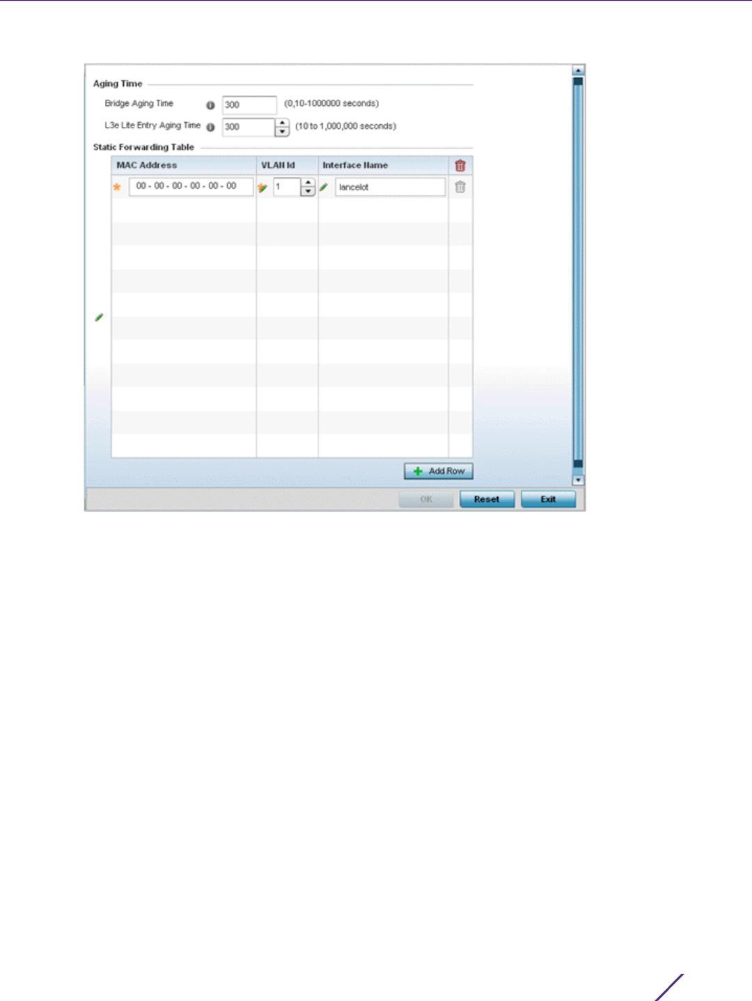
Device Configuration
Wireless Controller and Service Platform System Reference Guide 5 - 179
Figure 5-99 Profile Overrides - Network Forwarding Database screen
6 Define or override a Bridge Aging Time between 0, 10-1,000,000 seconds.
The aging time defines the interval an entry remains in the a bridge’s forwarding table before being deleted
due to lack of activity. If an entry replenishments a destination generating continuous traffic, this timeout value
will never be invoked. However, if the destination becomes idle, the timeout value represents the length of time
that must be exceeded before an entry is deleted from the forwarding table. The default setting is 300
seconds.
7 Define or override a L3e Lite Entry Aging Time between 10-1,000,000 seconds.
The default setting is 300 seconds. This setting is not available on all device platforms.
8Use the + Add Row button to create a new row within the Static Forwarding Table.
9 Set or override a destination MAC Address. The bridge reads the packet’s destination MAC address and decides
to forward the packet or drop (filter) it. If it’s determined the destination MAC is on a different network, it
forwards the packet to the segment. If the destination MAC is on the same network segment, the packet is
dropped (filtered).
10 Define or override the target VLAN ID if the destination MAC is on a different network segment.
11 Provide an Interface Name used as the target destination interface for the target MAC address.
12 Select OK to save the changes and overrides. Select Reset to revert to the last saved configuration.

Device Configuration
Wireless Controller and Service Platform System Reference Guide 5 - 180
5.2.8.13 Overriding a Profile’s Bridge VLAN Configuration
Overriding a Profile’s Network Configuration
A Virtual LAN (VLAN) is separately administrated virtual network within the same physical managed network.
VLANs are broadcast domains defined within switches to allow control of broadcast, multicast, unicast, and
unknown unicast within a Layer 2 device.
Administrators often need to route traffic to interoperate between different VLANs. Bridging VLANs are only for
non-routable traffic, like tagged VLAN frames destined to some other device which will untag it. When a data
frame is received on a port, the VLAN bridge determines the associated VLAN based on the port of reception.
Using forwarding database information, the Bridge VLAN forwards the data frame on the appropriate port(s).
VLAN's are useful to set separate networks to isolate some computers from others, without actually having to have
separate cabling and Ethernet switches. Controllers and service platforms can do this on their own, without need
for the computer or other gear to know itself what VLAN it's on (this is called port-based VLAN, since it's assigned
by port of the switch). Another common use is to put specialized devices like VoIP Phones on a separate network
for easier configuration, administration, security, or quality of service.
Two main VLAN bridging modes are available:
•Tunnel Mode: In tunnel mode, the traffic at the Access Point is always forwarded through the best path. The
Access Point decides the best path to use and appropriately forwards packets. Setting the VLAN to tunnel
mode ensures packets are Bridge packets between local Ethernet ports, any local radios, and tunnels to other
APs and wireless controller.
•Local Mode: Local mode is typically configured in remote branch offices where traffic on remote private LAN
segment needs to be bridged locally. Local mode implies that the wired and the wireless traffic are to be
bridged locally.
To define a bridge VLAN configuration or override for a device profile:
1Select
Devices from the Configuration tab.
The Device Configuration screen displays a list of managed devices or peer controllers, service platforms or
Access Points.
2 Select a target device (by double-clicking it) from amongst those displayed within the Device Configuration
screen.
Devices can also be selected directly from the Device Browser in the lower, left-hand, side of the UI.
3Select
Profile Overrides from the Device menu to expand it into sub menu options.
4Select
Network to expand its sub menu options.
5Select
Bridge VLAN.
NOTE: A blue override icon (to the left of a parameter) defines the parameter as
having an override applied. To remove an override go to the Basic Configuration
section of the device and click the Clear Overrides button. This removes all
overrides from the device.

Device Configuration
Wireless Controller and Service Platform System Reference Guide 5 - 181
Figure 5-100 Profile Overrides - Network Bridge VLAN screen
6 Review the following VLAN configuration parameters to determine whether an override is warranted:
VLAN Lists the numerical identifier defined for the Bridge VLAN when it was
initially created. The available range is from 1 - 495. This value cannot be
modified during the edit process.
Description Lists a VLAN description assigned when the VLAN was created or
modified. The description should be unique to the VLAN’s specific
configuration and help differentiate it from other VLANs with similar
configurations.
Edge VLAN Mode Defines whether the VLAN is currently in edge VLAN mode. A green
check mark defines the VLAN as extended. An edge VLAN is the VLAN
where hosts are connected. For example, if VLAN 10 is defined with
wireless clients, and VLAN 20 is where the default gateway resides,
VLAN 10 should be marked as an edge VLAN and VLAN 20 shouldn’t be
marked as an edge VLAN. When defining a VLAN as edge VLAN, the
firewall enforces additional checks on hosts in that VLAN. For example, a
host cannot move from an edge VLAN to another VLAN and still keep
firewall flows active.
Trust ARP Responses Trusted ARP packets are used to update the IP-MAC Table to prevent IP
spoof and arp-cache poisoning attacks. When ARP trust is enabled, a
green check mark displays. When disabled, a red “X” displays.
Trust DHCP Responses When enabled, DHCP packets from a DHCP server are trusted and
permissible. DHCP packets update the DHCP Snoop Table to prevent IP
spoof attacks. When DHCP trust is enabled, a green check mark
displays. When disabled, a red “X” displays.

Device Configuration
Wireless Controller and Service Platform System Reference Guide 5 - 182
7Select
Add to define a new Bridge VLAN configuration, Edit to modify or override an existing Bridge VLAN
configuration or Delete to remove a VLAN configuration.
IPv6 Firewall Lists whether IPv6 is enabled on this bridge VLAN. A green checkmark
defines this setting as enabled. A red X defines this setting as disabled.
IPV6 provides enhanced identification and location information for
computers on networks routing traffic across the Internet. IPv6
addresses are composed of eight groups of four hexadecimal digits
separated by colons. IPv6 hosts can configure themselves automatically
when connected to an IPv6 network using the neighbor discovery
protocol via ICMPv6 router discovery messages. When first connected to
a network, a host sends a link-local router solicitation multicast request
for its configuration parameters; routers respond to such a request with
a router advertisement packet that contains Internet Layer configuration
parameters.
DHCPv6 Trust Lists whether DHCPv6 responses are trusted on this bridge VLAN. A
green checkmark defines this setting as enabled. A red X defines this
setting as disabled. If enabled, only DHCPv6 responses are trusted and
forwarded over the bridge VLAN.
RA Guard Lists whether router advertisements (RA) are allowed on this bridge
VLAN. A green checkmark defines this setting as enabled. A red X
defines this setting as disabled. RAs are periodically sent to hosts or
sent in response to solicitation requests. The advertisement includes
IPv6 prefixes and other subnet and host information.
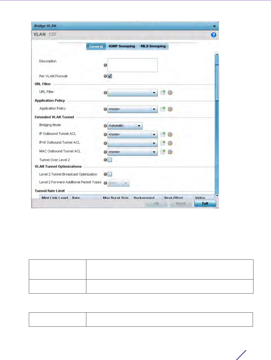
Device Configuration
Wireless Controller and Service Platform System Reference Guide 5 - 183
Figure 5-101 Profile Overrides - Network Bridge VLAN screen, General tab
The General tab displays by default.
8 If adding a new Bridge VLAN configuration, use the spinner control to define or override a VLAN ID between 1 -
4094. This value must be defined and saved before the General tab can become enabled and the remainder of
the settings defined. VLAN IDs 0 and 4095 are reserved and unavailable.
9 Set or override the following General bridge VLAN parameters:
10 Set or override the following URL Filter parameters. URL filters are used to control access to specific resources
on the Internet.
Description If creating a new Bridge VLAN, provide a description (up to 64
characters) unique to the VLAN’s specific configuration to help
differentiate it from other VLANs with similar configurations.
Per VLAN Firewall Enable this setting to provide firewall allow and deny conditions over the
bridge VLAN. This setting is enabled by default.
URL Filter Use the drop-down menu to select a URL filter to use with this Bridge
VLAN.

Device Configuration
Wireless Controller and Service Platform System Reference Guide 5 - 184
11 Use the drop-down to select the appropriate Application Policy to use with this Bridge VLAN configuration. An
application policy defines the rules or actions executed on recognized HTTP (Facebook), enterprise (Webex)
and peer-to-peer (gaming) applications or application-categories.
12 Set or override the following Extended VLAN Tunnel parameters:
13 Select the Level 2 Tunnel Broadcast Optimization checkbox to enable broadcast optimization on this bridge
VLAN. L2 Tunnel Broadcast Optimization prevents flooding of ARP packets over the virtual interface. Based on
the learned information, ARP packets are filtered at the wireless controller level. This option is enabled by
default.
14 If enabling L2 tunnel broadcast optimization, set the Level 2 Forward Additional Packet Types as None or
WNMP to specify if additional packet types are forwarded or not across the L2 tunnel. By default, L2 tunnel
broadcast optimization disables Wireless Network Management Protocol (WNMP) packet forwarding also
across the L2 tunnel. Use this option to enable the forwarding of only WNMP packets. The default value is
None.
Bridging Mode Specify one of the following bridging mode for use on the VLAN.
•Automatic - Select automatic mode to let the controller or service
platform determine the best bridging mode for the VLAN.
•Local - Select Local to use local bridging mode for bridging traffic on the
VLAN.
•Tunnel - Select Tunnel to use a shared tunnel for bridging traffic on the
VLAN.
•Isolated Tunnel - Select isolated-tunnel to use a dedicated tunnel for
bridging traffic on the VLAN.
IP Outbound Tunnel
ACL
Select an IP Outbound Tunnel ACL for outbound traffic from the drop-
down menu. If an appropriate outbound IP ACL is not available, select
the Create button.
IPv6 Outbound Tunnel
ACL
Select an IPv6 Outbound Tunnel ACL for outbound IPv6 traffic from the
drop-down menu. If an appropriate outbound IPv6 ACL is not available,
select the Create button.
MAC Outbound Tunnel
ACL
Select a MAC Outbound Tunnel ACL for outbound traffic from the drop-
down menu. If an appropriate outbound MAC ACL is not available, select
the Create button.
Tunnel Over Level 2 Select this option to allow VLAN traffic to be tunneled over level 2 links.
This setting is disabled by default.
NOTE: Local and Automatic bridging modes do not work with ACLs. ACLs can only
be used with tunnel or isolated-tunnel modes.

Device Configuration
Wireless Controller and Service Platform System Reference Guide 5 - 185
15 Set the following Tunnel Rate Limit parameters:
16 Set or override the following Layer 2 Firewall parameters:
17 Set the following IPv6 Settings:
18 Refer to the Captive Portal field to select an existing captive portal configuration to apply access restrictions to
the bridge VLAN configuration.
A captive portal is an access policy for providing temporary and restrictive access using a standard Web
browser. Captive portals provides authenticated access by capturing and re-directing a wireless user's Web
browser session to a captive portal login page where the user must enter valid credentials to access to the
Mint Link Level Select the MINT link level being rate limited for layer 2 from the drop-
down menu.
Rate Define a transmit rate limit between 50 - 1,000,000 kbps. This limit
constitutes a threshold for the maximum the number of packets
transmitted or received over the bridge VLAN. Traffic that exceeds the
defined rate is dropped and a log message is generated. The default
setting is 5,000 kbps.
Maximum Burst Size Set a maximum burst size between 0 - 1024 kbytes. The smaller the
burst, the less likely the receive packet transmission will result in
congestion. The default burst size is 320 kbytes.
Background Set the random early detection threshold in % for low priority
background traffic. Set a value from 1 - 100%. The default is 50%.
Best-Effort Set the random early detection threshold in % for low priority best-
effort traffic. Set a value from 1 - 100%. The default is 50%.
Video Set the random early detection threshold in % for high priority video
traffic. Set a value from 1 - 100%. The default is 25%.
Voice Set the random early detection threshold in % for high priority voice
traffic. Set a value from 1 - 100%. The default is 25%.
Trust ARP Response Select the check box to use trusted ARP packets to update the DHCP
Snoop Table to prevent IP spoof and ARP-cache poisoning attacks. This
feature is disabled by default.
Trust DHCP Responses Select the check box to use DHCP packets from a DHCP server as
trusted and permissible within the managed network. DHCP packets are
used to update the DHCP Snoop Table to prevent IP spoof attacks. This
feature is disabled by default.
Edge VLAN Mode Select the check box to enable edge VLAN mode. When selected, the
edge controller or service platform’s IP address in the VLAN is not used
for normal operations, as its now designated to isolate devices and
prevent connectivity. This feature is enabled by default.
IPv6 Firewall Select this option to enable IPv6 on this bridge VLAN. This setting is
enabled by default.
DHCPv6 Trust Select this option to enable the trust all DHCPv6 responses on this
bridge VLAN. DHCPv6 is a networking protocol for configuring IPv6
hosts with IP addresses, IP prefixes or other configuration attributes
required on an IPv6 network. This setting is enabled by default.
RA Guard Select this option to enable router advertisements or ICMPv6 redirects
on this bridge VLAN. This setting is enabled by default.
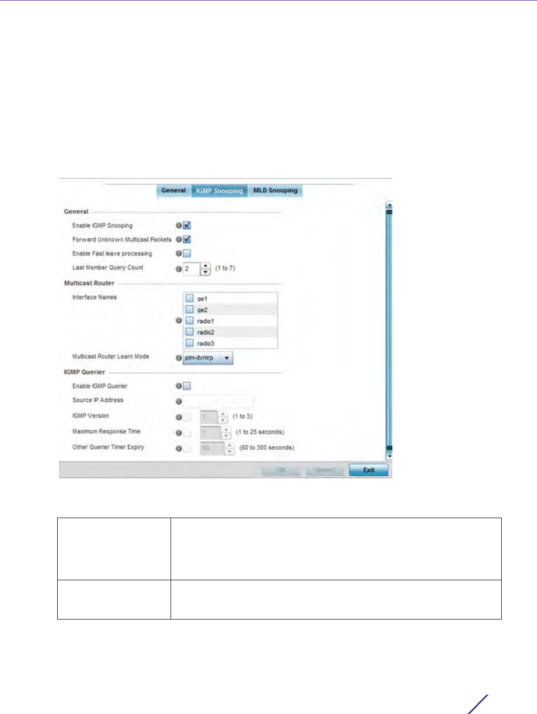
Device Configuration
Wireless Controller and Service Platform System Reference Guide 5 - 186
network. Once logged into the captive portal, additional Terms and Agreement, Welcome, Fail and No Service
pages provide the administrator with a number of options on captive portal screen flow and user appearance.
If an existing captive portal does not suite the bridge VLAN configuration, either select the Edit icon to modify
an existing configuration or select the Create icon to define a new configuration that can be applied to the
bridge VLAN. For information on configuring a captive portal policy, see Configuring Captive Portal Policies on
page 11-1.
19 Refer to the Captive Portal Snoop IPv6 Subnet field to configure the subnet on which IPv6 snooping is enabled/
disabled for wired captive portal support. Up to 16 excluded addresses are permitted.
20 Select the IGMP Snooping tab.
Figure 5-102 Profile Overrides - Network Bridge VLAN screen, IGMP Snooping tab
21 Define the following General settings:
Enable IGMP Snooping Select this option to enable IGMP snooping. If disabled, snooping on a
per VLAN basis is also disabled. This feature is enabled by default. If
disabled, the settings under the bridge configuration are overridden. For
example, if IGMP snooping is disabled, but the bridge VLAN is enabled,
the setting is disabled.
Forward Unknown
Multicast Packets
Select this option to enable the forwarding of multicast packets from
unregistered multicast groups. If disabled (the default setting), the
unknown multicast forward feature is also disabled for individual VLANs.

Device Configuration
Wireless Controller and Service Platform System Reference Guide 5 - 187
22 Define the following Multicast Router settings
23 Define the following IGMP Querier settings:
24 Select the OK button located at the bottom right of the screen to save the changes to the IGMP Snooping tab.
Select Reset to revert to the last saved configuration.
Enable Fast leave
processing
Select this option to remove a Layer 2 LAN interface from the IGMP
snooping forwarding table entry without initially sending IGMP group-
specific queries to the interface. When receiving a group specific
IGMPv2 leave message, IGMP snooping removes the interface from the
Layer 2 forwarding table entry for that multicast group, unless a
multicast router was learned on the port. Fast-leave processing
enhances bandwidth management for all hosts on the network. This
setting is disabled by default.
Last Member Query
Count
Specify the number (1 - 7) of group specific queries sent before
removing an IGMP snooping entry. The default settings is 2.
Interface Names Select the ge1 or radio interfaces used to IGMP snooping over a
multicast router.
Multicast Router Learn
Mode
Set the pim-dvmrp or static multicast routing learn mode. DVMRP
builds a parent-child database using a constrained multicast model to
build a forwarding tree rooted at the source of the multicast packets.
Multicast packets are initially flooded down this source tree. If
redundant paths are on the source tree, packets are not forwarded
along those paths.
Enable IGMP Querier Select this option to enable IGMP querier. IGMP snoop querier is used to
keep host memberships alive. It’s primarily used in a network where
there’s a multicast streaming server and hosts subscribed to the server
and no IGMP querier present. An IGMP querier sends out periodic IGMP
query packets. Interested hosts reply with an IGMP report packet. IGMP
snooping is only conducted on wireless radios. IGMP multicast packets
are flooded on wired ports. IGMP multicast packet are not flooded on
the wired port. IGMP membership is also learnt on it and only if present,
then it is forwarded on that port.
Source IP Address If enabling IGMP querier, set the source IP address used for IGMP
snooping over a multicast router.
IGMP Version Use the spinner control to set the IGMP version compatibility to either
version 1, 2 or 3. IGMPv1 is defined by RFC 1112, IGMPv2 is defined by
RFC 2236 and IGMPv3 defined by RFC 4604 which defines both
IGMPv3 and MLDv2. IGMPv2 improves over IGMPv1 by adding the ability
for a host to signal desire to leave a multicast group. IGMPv3 improves
over IGMPv2 by adding the ability to listen to multicast traffic
originating from a set of source IP addresses exclusively.
Maximum Response
Time
Specify the maximum interval (from 1 - 25 seconds) before sending a
responding report. When no reports are received from a radio, radio
information is removed from the snooping table. The controller or
service platform only forwards multicast packets to radios present in the
snooping table. For IGMP reports from wired ports, the controller or
service platform forwards these reports to the multicast router ports.
The default setting is 1 seconds.
Other Querier Timer
Expiry
Specify an interval (from 60 - 300 seconds) used as a timeout interval
for other querier resources.
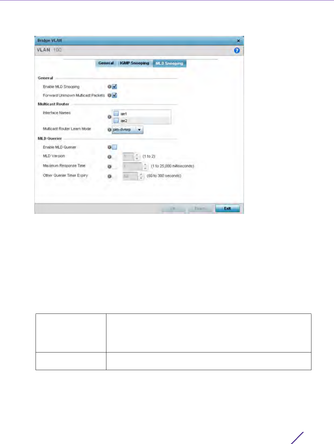
Device Configuration
Wireless Controller and Service Platform System Reference Guide 5 - 188
25 Select the MLD Snooping tab.
Figure 5-103 Profile Overrides - Network Bridge VLAN screen, MLD Snooping tab
26 Define the following General MLD snooping parameters for the bridge VLAN configuration:
Multicast Listener Discovery (MLD) snooping enables a controller, service platform or Access Point to examine
MLD packets and make forwarding decisions based on content. MLD is used by IPv6 devices to discover
devices wanting to receive multicast packets destined for specific multicast addresses. MLD uses multicast
listener queries and multicast listener reports to identify which multicast addresses have listeners and join
multicast groups.
MLD snooping caps the flooding of IPv6 multicast traffic on controller, service platform or Access Point VLANs.
When enabled, MLD messages are examined between hosts and multicast routers and to discern which hosts
are receiving multicast group traffic. The controller, service platform or Access Point then forwards multicast
traffic only to those interfaces connected to interested receivers instead of flooding traffic to all interfaces.
Enable MLD Snooping Enable MLD snooping to examine MLD packets and support content
forwarding on this bridge VLAN. Packets delivered are identified by a
single multicast group address. Multicast packets are delivered using
best-effort reliability, just like IPv6 unicast. MLD snooping is enabled by
default.
Forward Unknown
Unicast Packets
Use this option to either enable or disable IPv6 unknown unicast
forwarding. This setting is enabled by default.

Device Configuration
Wireless Controller and Service Platform System Reference Guide 5 - 189
27 Define the following Multicast Router settings
28 Set the following MLD Querier parameters for the profile’s bridge VLAN configuration:
29 Select the OK button to save the changes and overrides. Select Reset to revert to the last saved configuration.
5.2.8.14 Overriding a Profile’s Cisco Discovery Protocol Configuration
Overriding a Profile’s Network Configuration
The Cisco Discovery Protocol (CDP) is a proprietary data link layer network protocol implemented in Cisco
networking equipment and used to share information about network devices.
To override a CDP configuration:
1Select
Devices from the Configuration tab.
The Device Configuration screen displays a list of managed devices or peer controllers, service platforms or
Access Points.
2 Select a target device (by double-clicking it) from amongst those displayed within the Device Configuration
screen.
Devices can also be selected directly from the Device Browser in the lower, left-hand, side of the UI.
3Select
Profile Overrides from the Device menu to expand it into sub menu options.
4Select
Network to expand its sub menu options.
5Select
Cisco Discovery Protocol.
Interface Names Select the ge or radio interfaces used for MLD snooping.
Multicast Router Learn
Mode
Set the pim-dvmrp or static multicast routing learn mode. DVMRP builds
a parent-child database using a constrained multicast model to build a
forwarding tree rooted at the source of the multicast packets. Multicast
packets are initially flooded down this source tree. If redundant paths
are on the source tree, packets are not forwarded along those paths.
Enable MLD Querier Select the option to enable MLD querier on the controller, service
platform or Access Point. When enabled, the device sends query
messages to discover which network devices are members of a given
multicast group. This setting is enabled by default.
MLD Version Define whether MLD version 1 or 2 is utilized with the MLD querier. MLD
version 1 is based on IGMP version 2 for IPv4. MLD version 2 is based on
IGMP version 3 for IPv4 and is fully backward compatible. IPv6 multicast
uses MLD version 2. The default MLD version is 2.
Maximum Response
Time
Specify the maximum response time (from 1 - 25,000 milliseconds)
before sending a responding report. Queriers use MLD reports to join
and leave multicast groups and receive group traffic. The default setting
is 1 milliseconds.
Other Querier Timer
Expiry
Specify an interval in either Seconds (60 - 300) or Minutes (1 - 5) used
as a timeout interval for other querier resources. The default setting is
60 seconds
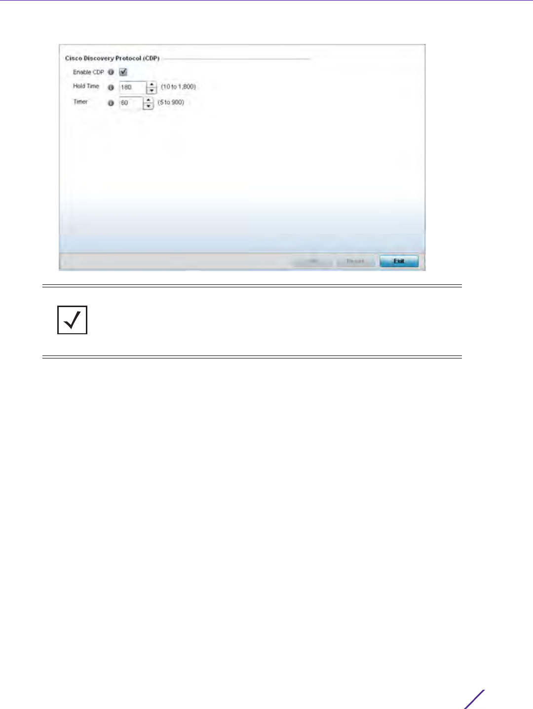
Device Configuration
Wireless Controller and Service Platform System Reference Guide 5 - 190
Figure 5-104 Profile Overrides - Network Cisco Discovery Protocol screen
6Check the Enable CDP box to enable CDP on the device.
7 Refer to the Hold Time field and use the spinner control to define a hold time between 10 - 1800 seconds for
transmitted CDP Packets. The default value is 180 seconds.
8 Refer to the Timer field and use the spinner control to define a interval between 5 - 900 seconds to transmit
CDP Packets. The default value is 60 seconds.
9 Select the OK button to save the changes and overrides. Select Reset to revert to the last saved configuration.
5.2.8.15 Overriding a Profile’s Link Layer Discovery Protocol Configuration
Overriding a Profile’s Network Configuration
The Link Layer Discovery Protocol (LLDP) or IEEE 802.1AB is a vendor-neutral data link layer protocol used by
network devices for advertising (announcing) their identity, capabilities, and interconnections
on a IEEE 802 LAN network. The protocol is formally referred to by the IEEE as Station and Media Access Control
Connectivity Discovery. Both LLDP snooping and ability to generate and transmit LLDP packets will be provided.
Information obtained via CDP and LLDP snooping is available in the UI. In addition, information obtained via CDP /
LLDP snooping is provided by an AP during the adoption process, so the L2 switch device name detected by the
AP can be used as a criteria in the auto provisioning policy.
To override a LLDP configuration:
NOTE: A blue override icon (to the left of a parameter) defines the parameter as
having an override applied. To remove an override go to the Basic Configuration
section of the device and click the Clear Overrides button. This removes all
overrides from the device.
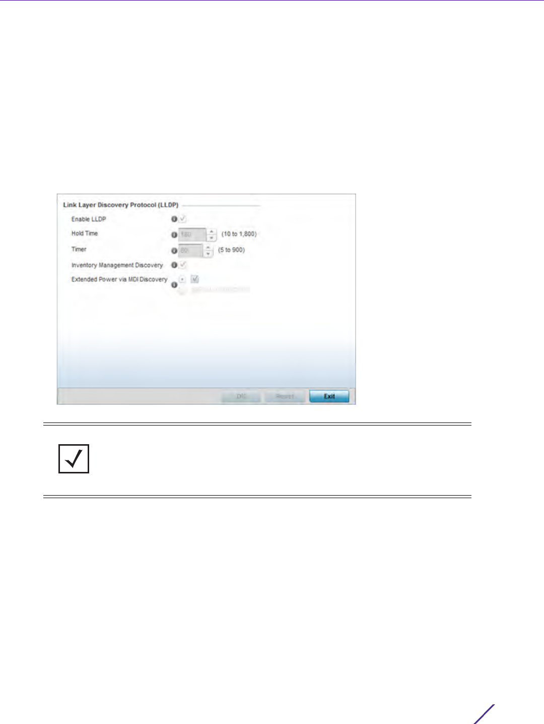
Device Configuration
Wireless Controller and Service Platform System Reference Guide 5 - 191
1Select
Devices from the Configuration tab.
The Device Configuration screen displays a list of managed devices or peer controllers, service platforms or
Access Points.
2 Select a target device (by double-clicking it) from amongst those displayed within the Device Configuration
screen.
Devices can also be selected directly from the Device Browser in the lower, left-hand, side of the UI.
3Select
Profile Overrides from the Device menu to expand it into sub menu options.
4Select
Network to expand its sub menu options.
5Select
Link Layer Discovery Protocol.
Figure 5-105 Profile Overrides - Network Link Layer Discovery Protocol screen
6Check the Enable LLDP box to enable Link Layer Discovery Protocol on the device.
7 Refer to the Hold Time field and use the spinner control to define a hold time between 10 - 1800 seconds for
transmitted LLDP Packets. The default value is 180 seconds.
8 Refer to the Timer field and use the spinner control to define the interval between 5 - 900 seconds to transmit
LLDP packets. The default value is 60 seconds.
9Check the Inventory Management Discovery box to enable this feature. Inventory Management Discovery is
used to track and identify inventory attributes including manufacturer, model, or software version.
10 Extended Power via MDI Discovery provides detailed power information through end points and other
connected devices. Select the Extended Power via MDI Discovery box to enable this feature. or select the
Default for Type option to use a WiNG internal default value.
11 Select the OK button to save the changes and overrides. Select Reset to revert to the last saved configuration.
NOTE: A blue override icon (to the left of a parameter) defines the parameter as
having an override applied. To remove an override go to the Basic Configuration
section of the device and click the Clear Overrides button. This removes all
overrides from the device.
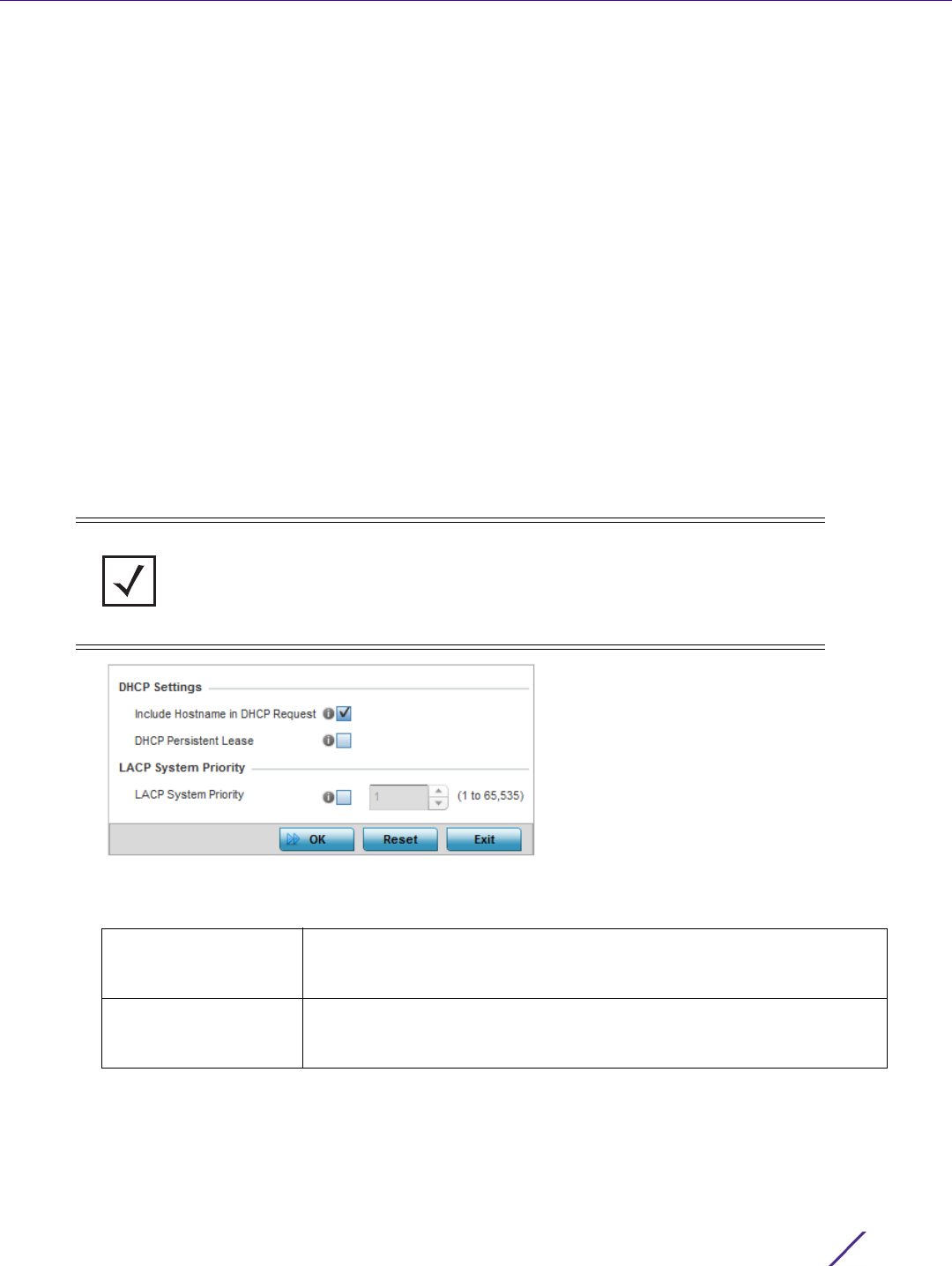
Device Configuration
Wireless Controller and Service Platform System Reference Guide 5 - 192
5.2.8.16 Overriding a Profile’s Miscellaneous Network Configuration
Overriding a Profile’s Network Configuration
A profile can include a hostname within a DHCP lease for a requesting device. This helps an administrator track the
leased DHCP IP address by hostname for the device profile. When numerous DHCP leases are assigned, an
administrator can better track the leases when hostnames are used instead of devices.
To include a hostnames in DHCP request:
1Select
Devices from the Configuration tab.
The Device Configuration screen displays a list of managed devices or peer controllers, service platforms or
Access Points.
2 Select a target device (by double-clicking it) from amongst those displayed within the Device Configuration
screen.
Devices can also be selected directly from the Device Browser in the lower, left-hand, side of the UI.
3Select
Profile Overrides from the Device menu to expand it into sub menu options.
4Select
Network to expand its sub menu options.
5Select
Miscellaneous.
Figure 5-106 Profile Overrides - Network Miscellaneous screen
6 Refer to the DHCP Settings section to configure miscellaneous DHCP Settings.
7 Select the LACP System Priority value in the range of 1 - 65,535. The system with a lower number will have a
higher priority when setting up a connection with a LACP peer. If a value is not set for this field, the default
value of 32768 is used.
Link Aggregation Control Protocol (LACP) enables combining and managing multiple physical connections like
Ethernet ports as a single logical channel as defined in the IEEE 802.1ax standard. LACP provides redundancy
NOTE: A blue override icon (to the left of a parameter) defines the parameter as
having an override applied. To remove an override go to the Basic Configuration
section of the device and click the Clear Overrides button. This removes all
overrides from the device.
Include Hostname in
DHCP Request
Select the Include Hostname in DHCP Request option to include a
hostname within a DHCP lease for a requesting device. This feature is
enabled by default.
DHCP Persistent Lease Check this option to enable a persistent DHCP lease for the device. A
persistent DHCP lease assigns the same IP Address and other network
information to the device each time it renews its DHCP lease.

Device Configuration
Wireless Controller and Service Platform System Reference Guide 5 - 193
and increase in throughput for connections between two peers. LACP provides automatic recovery in cases
where one or more of the physical links - making up the aggregation - fail. Similarly, LACP also provides a
theoretical boost in speed compared to an individual physical link.
8 To enable critical resource monitoring for the device, select a Critical Resource Policy from the drop-down
menu in the Critical Resource Monitoring section. If a new critical resource monitoring policy is needed click the
Create button and specify the Ping Interval, IP Address, Ping Mode and VLAN for the devices being monitored.
9 Select the OK button to save the changes and overrides. Select Reset to revert to the last saved configuration.
5.2.8.17 Overriding a Profile’s Network Alias Configuration
Overriding a Profile’s Network Configuration
With large deployments, the configuration of remote sites utilizes a set of shared attributes, of which a small set of
attributes are unique for each location. For such deployments, maintaining separate configuration (WLANs,
profiles, policies and ACLs) for each remote site is complex. Migrating any global change to a particular
configuration item to all the remote sites is a complex and time consuming operation.
Also, this practice does not scale gracefully for quick growing deployments.
An alias enables an administrator to define a configuration item, such as a hostname, as an alias once and use the
defined alias across different configuration items such as multiple ACLs.
Once a configuration item, such as an ACL, is utilized across remote locations, the Alias used in the configuration
item (ACL) is modified to meet local deployment requirement. Any other ACL or other configuration items using
the modified alias also get modified, simplifying maintenance at the remote deployment.
Aliases have scope depending on where the Alias is defined. Alias are defined with the following scopes:
•Global aliases are defined from the Configuration > Network > Alias screen. Global aliases are available for use
globally across all devices, profiles and RF Domains in the system.
•Profiles aliases are defined from the Configuration > Devices > System Profile > Network > Alias screen. Profile
aliases are available for use to a specific group of wireless controllers or Access Points. Alias values defined in a
profile override the alias values defined within global aliases.
•RF Domain aliases are defined from the Configuration > Devices > RF Domain > Alias screen. RF Domain aliases
are available for use for a site as a RF Domain is site specific. RF Domain alias values override alias values
defined in a global alias or a profile alias configuration.
•Device aliases are defined from the Configuration > Devices > Device Overrides > Network > Alias screen.
Device aliases are utilized by a singular device only. Device alias values override global, profile or RF Domain
alias configurations.
Using an alias, configuration changes made at a remote location override any updates at the management center.
For example, if an network alias defines a network range as 192.168.10.0/24 for the entire network, and at a remote
deployment location, the local network range is 172.16.10.0/24, the network alias can be overridden at the
deployment location to suit the local requirement. For the remote deployment location, the network alias work
NOTE: Disable or physically disconnect interfaces that do not use spanning tree to
prevent loop formation until LACP is fully configured on both the local WiNG device
and the remote device.

Device Configuration
Wireless Controller and Service Platform System Reference Guide 5 - 194
with the 172.16.10.0/24 network. Existing ACLs using this network alias need not be modified and will work with the
local network for the deployment location. This simplifies ACL definition and management while taking care of
specific local deployment requirements.
For more information, refer to the following:
•Basic Alias
•Network Group Alias
•Network Service Alias
5.2.8.17.1 Basic Alias
A basic alias is a set of configurations consisting of VLAN, Host, Network and Address Range alias configurations.
A VLAN alias is a configuration for optimal VLAN re-use and management for local and remote deployments. A
host alias configuration is for a particular host device’s IP address. A network alias configuration is utilized for an IP
address on a particular network. An address range alias is a configuration for a range of IP addresses.
To set a network basic alias configuration:
1Select
Devices from the Configuration tab.
The Device Configuration screen displays a list of managed devices or peer controllers, service platforms or
Access Points.
2 Select a target device (by double-clicking it) from amongst those displayed within the Device Configuration
screen.
Devices can also be selected directly from the Device Browser in the lower, left-hand, side of the UI.
3Select
Profile Overrides from the Device menu to expand it into sub menu options.
4Select
Network to expand its sub menu options.
5Select
Alias.
The Alias screen displays with the Basic Alias tab displayed by default.
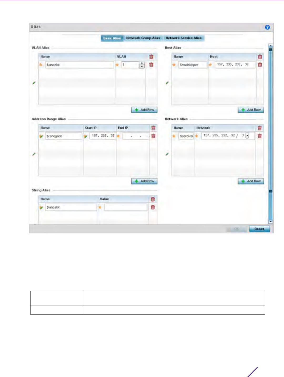
Device Configuration
Wireless Controller and Service Platform System Reference Guide 5 - 195
Figure 5-107 Network Basic Alias screen
6Select + Add Row to define VLAN Alias settings:
Use the VLAN Alias field to create unique aliases for VLANs that can be utilized at different deployments. For
example, if a VLAN ID is set as 10 for the central network, and the VLAN is set as 26 at a remote location, the
VLAN can be overridden at the remote location using an alias. At the remote location, the network is functional
with an ID of 26, but utilizes the name defined at the central local network. A new VLAN need not be created
specifically at the remote location.
7Select
+ Add Row to define Address Range Alias settings:
Use the Address Range Alias field to create aliases for IP address ranges that can be utilized at different
deployments. For example, if an ACL defines a pool of network addresses as 192.168.10.10 through
192.168.10.100 for an entire network, and a remote location’s network range is 172.16.13.20 through 172.16.13.110,
Name If adding a new VLAN Alias, provide it a distinguishing name up to 32
characters. The alias name always starts with a dollar sign ($).
Vlan Use the spinner control to set a numeric VLAN ID from 1 - 4094.

Device Configuration
Wireless Controller and Service Platform System Reference Guide 5 - 196
the remote location’s ACL can be overridden using an alias. At the remote location, the ACL works with the
172.16.13.20-110 address range. A new ACL need not be created specifically for the remote deployment location.
8Select
+ Add Row to define String Alias settings:
Use the String Alias field to create aliases for hosts that can be utilized at different deployments. For example,
if the main domain at a remote location is called loc1.domain.com and at another deployment location it is
called loc2.domain.com, the alias can be overridden at the remote location to suit the local (but remote)
requirement. At one remote location, the alias functions with the loc1.domain.com domain and at the other with
the loc2.domain.com domain.
9Select
+ Add Row to define Host Alias settings:
Use the Host Alias field to create aliases for hosts that can be utilized at different deployments. For example, if
a central network DNS server is set a static IP address, and a remote location’s local DNS server is defined, this
host can be overridden at the remote location. At the remote location, the network is functional with a local
DNS server, but uses the name set at the central network. A new host need not be created at the remote
location. This simplifies creating and managing hosts and allows an administrator to better manage specific
local requirements.
10 Select + Add Row to define Network Alias settings:
Use the Network Alias field to create aliases for IP networks that can be utilized at different deployments. For
example, if a central network ACL defines a network as 192.168.10.0/24, and a remote location’s network range
is 172.16.10.0/24, the ACL can be overridden at the remote location to suit their local (but remote) requirement.
At the remote location, the ACL functions with the 172.16.10.0/24 network. A new ACL need not be created
specifically for the remote deployment. This simplifies ACL definition and allows an administrator to better
manage specific local requirements.
11 Select OK when completed to update the set of basic alias rules. Select Reset to revert the screen back to its
last saved configuration.
Name If adding a new Address Alias, provide it a distinguishing name up to 32
characters. The alias name always starts with a dollar sign ($).
Start IP Set a starting IP address used with a range of addresses utilized with the
address range alias.
End IP Set an ending IP address used with a range of addresses utilized with the
address range alias.
Name If adding a new String Alias, provide it a distinguishing name up to 32
characters. The alias name always starts with a dollar sign ($).
Value Provide a string value to use in the alias.
Name If adding a new Host Alias, provide it a distinguishing name up to 32
characters. The alias name always starts with a dollar sign ($).
Host Set the IP address of the host machine.
Name If adding a new Network Alias, provide it a distinguishing name up to 32
characters. The alias name always starts with a dollar sign ($).
Network Provide a network address in the form of host/mask.
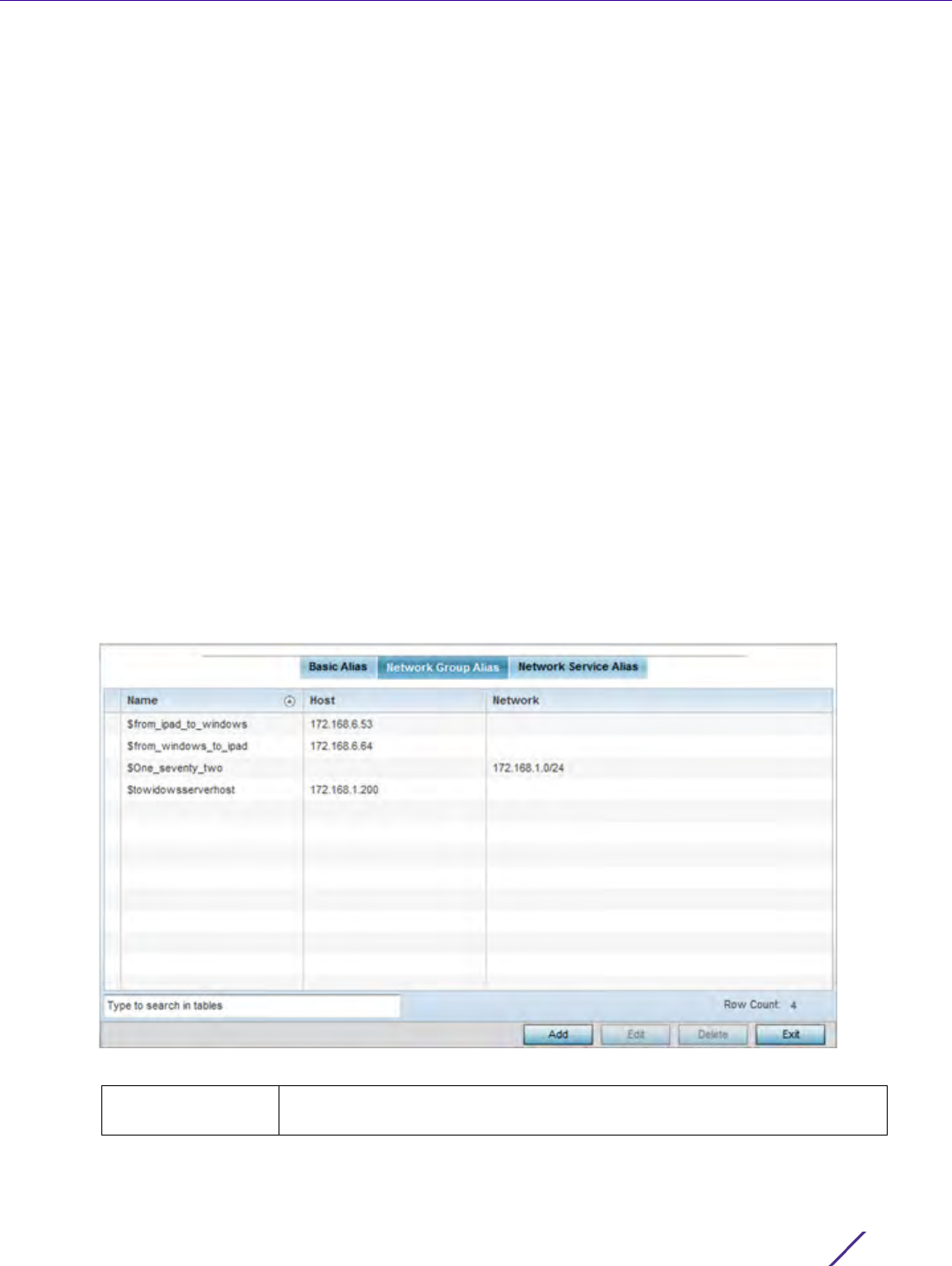
Device Configuration
Wireless Controller and Service Platform System Reference Guide 5 - 197
5.2.8.17.2 Network Group Alias
A network group alias is a set of configurations consisting of host and network configurations. Network
configurations are complete networks in the form of 192.168.10.0/24 or an IP address range in the form of
192.168.10.10-192.168.10.20. Host configurations are in the form of a single IP address, 192.168.10.23.
A network group alias can contain multiple definitions for a host, network, and IP address range. A maximum of
eight (8) Host entries, eight (8) network entries and eight (8) IP addresses range entries can be configured inside
a network group alias. A maximum of 32 network group alias entries can be created.
To set a network group alias configuration:
1Select
Devices from the Configuration tab.
The Device Configuration screen displays a list of managed devices or peer controllers, service platforms or
Access Points.
2 Select a target device (by double-clicking it) from amongst those displayed within the Device Configuration
screen.
Devices can also be selected directly from the Device Browser in the lower, left-hand, side of the UI.
3Select
Profile Overrides from the Device menu to expand it into sub menu options.
4Select
Network to expand its sub menu options.
5Select
Alias.
6 Select the Network Group Alias tab. The screen displays the attributes of existing network group alias
configurations.
Figure 5-108 Network Group Alias screen
Name Displays the administrator assigned name used with the network group
alias.
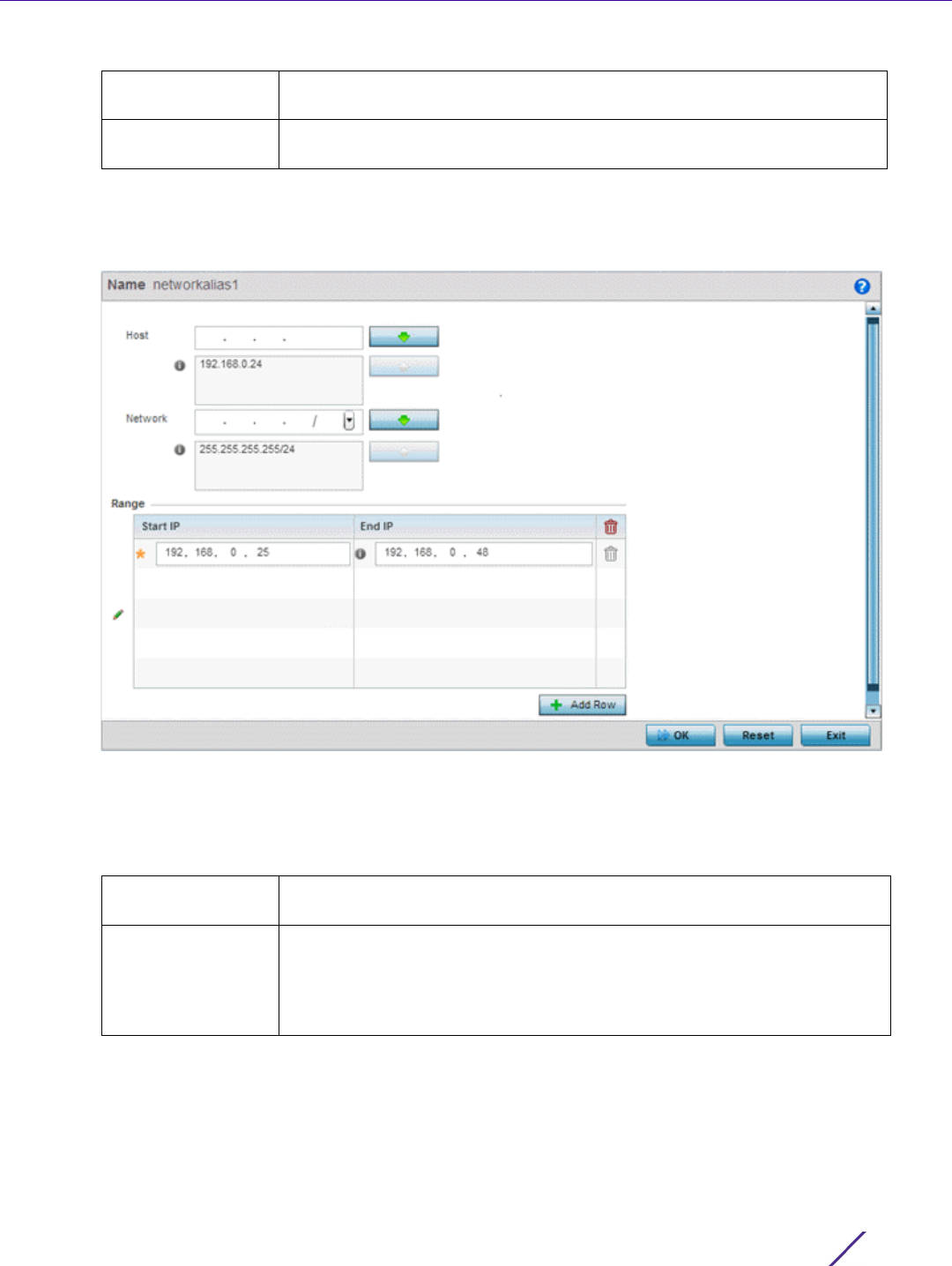
Device Configuration
Wireless Controller and Service Platform System Reference Guide 5 - 198
7Select
Add to create a new policy, Edit to modify the attributes of an existing policy or Delete to remove
obsolete policies.
8 Select the added row to expand it into configurable parameters for defining the network alias rule.
Figure 5-109 Network Group Alias Add screen
9 If adding a new Network Alias Rule, provide it a name up to 32 characters. The network group alias name
always starts with a dollar sign ($).
10 Define the following network group alias parameters:
11 Within the Range table, use the + Add Row button to specify the Start IP address and End IP address for the
alias range or double-click on an existing an alias range entry to edit it.
12 Select OK when completed to update the network alias rules. Select Reset to revert the screen back to its last
saved configuration.
Host Displays all the host aliases configured in the listed network group alias.
Displays a blank column if no host alias is defined.
Network Displays all network aliases configured in the listed network group alias.
Displays a blank column if no network alias is defined.
Host Specify the Host IP address for up to eight IP addresses supporting
network aliasing. Select the down arrow to add the IP address to the table.
Network Specify the netmask for up to eight IP addresses supporting network
aliasing. Subnets can improve network security and performance by
organizing hosts into logical groups. Applying the subnet mask to an IP
address separates the address into a host address and an extended
network address. Select the down arrow to add the mask to the table.
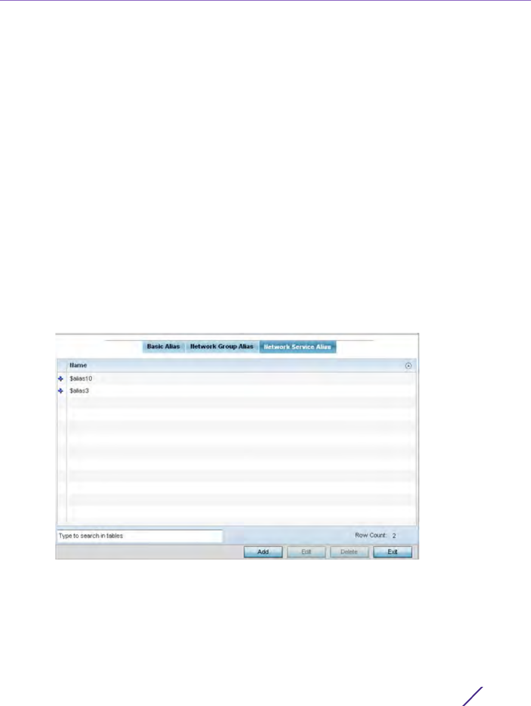
Device Configuration
Wireless Controller and Service Platform System Reference Guide 5 - 199
5.2.8.17.3 Network Service Alias
A network service alias is a set of configurations that consist of protocol and port mappings. Both source and
destination ports are configurable. For each protocol, up to 2 source port ranges and up to 2 destination port
ranges can be configured. A maximum of 4 protocol entries can be configured per network service alias.
Use a service alias to associate more than one IP address to a network interface, providing multiple connections to
a network from a single IP node.
To define a service alias configuration:
1Select
Devices from the Configuration tab.
The Device Configuration screen displays a list of managed devices or peer controllers, service platforms or
Access Points.
2 Select a target device (by double-clicking it) from amongst those displayed within the Device Configuration
screen.
Devices can also be selected directly from the Device Browser in the lower, left-hand, side of the UI.
3Select
Profile Overrides from the Device menu to expand it into sub menu options.
4Select
Network to expand its sub menu options.
5Select
Alias.
6 Select the Network Service Alias tab. The screen displays existing network service alias configurations.
Figure 5-110 Network Service Alias screen
7Select Add to create a new policy, Edit to modify the attributes of an existing policy or Delete to remove
obsolete policies.
8 Select the added row to expand it into configurable parameters for defining the service alias rule.
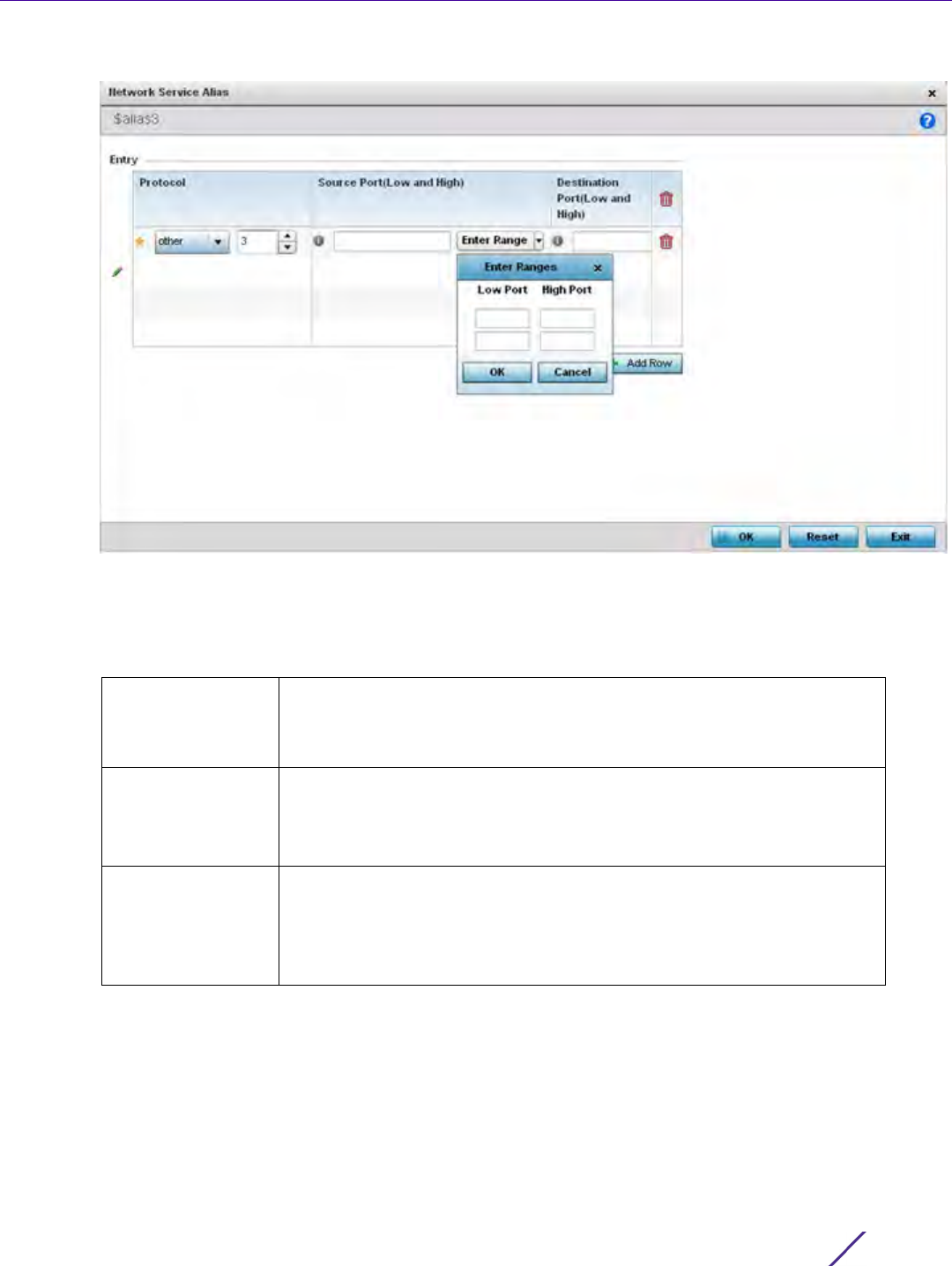
Device Configuration
Wireless Controller and Service Platform System Reference Guide 5 - 200
Figure 5-111 Network Service Alias Add screen
9 If adding a new Network Service Alias Rule, provide it a name up to 32 characters. Ensure a $ precedes the
name.
10 Select + Add Row and provide the following configuration parameters:
11 Within the Range field, use the + Add Row button to specify the Start IP address and End IP address for the
service alias range or double-click on an existing service alias range entry to edit it.
12 Select OK when completed to update the service alias rules. Select Reset to revert the screen back to its last
saved configuration.
Protocol Specify the protocol for which the alias has to be created. Use the drop
down to select the protocol from eigrp, gre, icmp, igmp, ip, vrrp, igp, ospf,
tcp and udp. Select other if the protocol is not listed. When a protocol is
selected, its protocol number is automatically selected.
Source Port
(Low and High)
This field is only relevant if the protocol is either tcp or udp.
Specify the source ports for this protocol entry. A range of ports can be
specified. Select the Enter Ranges button next to the field to enter a lower
and higher port range value. Up to eight (8) such ranges can be specified.
Destination Port
(Low and High)
This field is only relevant if the protocol is either tcp or udp.
Specify the destination ports for this protocol entry. A range of ports can
be specified. Select the Enter Ranges button next to the field to enter a
lower and higher port range value. Up to eight (8) such ranges can be
specified.
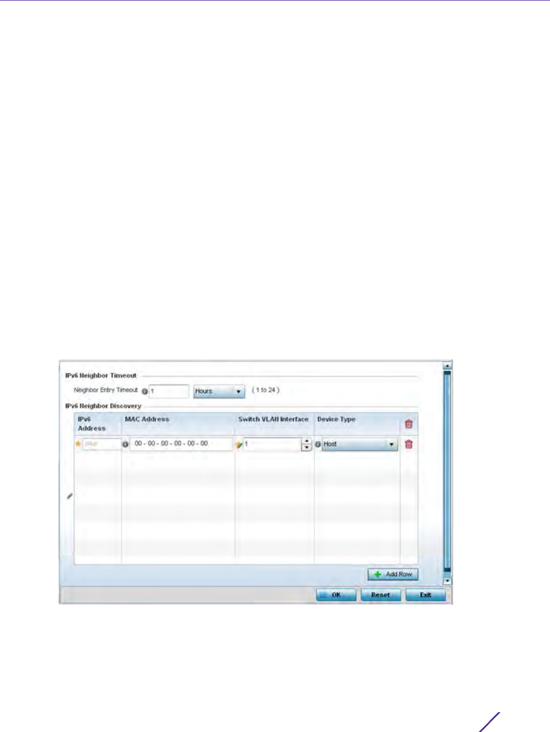
Device Configuration
Wireless Controller and Service Platform System Reference Guide 5 - 201
5.2.8.18 Overriding a Profile’s IPv6 Neighbor Configuration
Overriding a Profile’s Network Configuration
IPv6 neighbor discovery uses ICMP messages and solicited multicast addresses to find the link layer address of a
neighbor on the same local network, verify the neighbor’s reachability and track neighboring devices.
Upon receiving a neighbor solicitation message, the destination replies with neighbor advertisement (NA). The
source address in the NA is the IPv6 address of the device sending the NA message. The destination address in
the neighbor advertisement message is the IPv6 address of the device sending the neighbor solicitation. The data
portion of the NA includes the link layer address of the node sending the neighbor advertisement.
Neighbor solicitation messages also verify the availability of a neighbor once its the link layer address is identified.
When a node wants to verify the reachability of a neighbor, the destination address in a neighbor solicitation
message is the unicast address of the neighbor.
A neighbor is interpreted as reachable when an acknowledgment is returned indicating packets have been
received and processed. If packets are reaching the device, they’re also reaching the next hop neighbor, providing
a confirmation the next hop is reachable.
To set an IPv6 neighbor discovery configuration:
1Select
Configuration > Profiles > Network.
2 Expand the Network menu to display its submenu options.
3Select
IPv6 Neighbor.
Figure 5-112 IPv6 Neighbor screen
4Set an IPv6 Neighbor Entry Timeout in either Seconds (15 - 86,400), Minutes (1 - 1,440), Hours
(1 - 24) or Days (1). The default setting is 1 hour.

Device Configuration
Wireless Controller and Service Platform System Reference Guide 5 - 202
5Select
+ Add Row to define the configuration of IPv6 Neighbor Discovery configurations. A maximum of 256
neighbor entries can be defined.
6Select
OK to save the changes. Select Reset to revert to the last saved configuration.
5.2.9 Overriding a Profile’s Security Configuration
Profile Overrides
A profile can have its own firewall policy, wireless client role policy, WEP shared key authentication, NAT policy and
VPN policy (controllers and service platforms only) applied. If an existing firewall, client role or NAT policy is
unavailable, an administrator can be navigated from the Profiles section of the UI to the Configuration > Security
portion of the UI to create the required security policy configuration. Once created, a policy’s configuration can
have an override applied to meet the changing data protection requirements of a device’s environment. However,
in doing so the device must now be managed separately from the profile configuration shared by other devices
within the managed network.
For more information on applying an override to an existing device profile, refer to the following sections:
•Overriding a Profile’s General Security Settings
•Overriding a Profile’s Certificate Revocation List (CRL) Configuration
•Overriding a Profile’s RADIUS Trustpoint Configuration
•Overriding a Profile’s VPN Configuration
•Overriding a Profile’s Auto IPSec Tunnel Configuration
•Overriding a Profile’s NAT Configuration
•Overriding a Profile’s Bridge NAT Configuration
•Overriding a Profile’s Application Visibility Settings
5.2.9.1 Overriding a Profile’s General Security Settings
Overriding a Profile’s Security Configuration
A profile can leverage existing firewall, wireless client role and WIPS policies and apply them to the profile’s
configuration. This affords each profile a truly unique combination of data protection policies best meeting the
IPv6 Address Provide a static IPv6 IP address for neighbor discovery. IPv6 hosts can
configure themselves automatically when connected to an IPv6 network
using the Neighbor Discovery Protocol via Internet Control Message
Protocol version 6 (ICMPv6) router discovery messages. When first
connected to a network, a host sends a link-local router solicitation
multicast request for its configuration parameters; routers respond to
such a request with a router advertisement packet that contains Internet
Layer configuration parameters. IPv6 addresses are composed of eight
groups of four hexadecimal digits separated by colons.
MAC Address Enter the hardware encoded MAC addresses of up to 256 IPv6 neighbor
devices. A neighbor is interpreted as reachable when an
acknowledgment is returned indicating packets have been received and
processed. If packets are reaching the device, they’re also reaching the
next hop neighbor, providing a confirmation the next hop is reachable.
Switch VLAN Interface Use the spinner control to set the virtual interface (from 1 - 4094) used
for neighbor advertisements and solicitation messages.
Device Type Specify the device type for this neighbor solicitation is for. Options
include Host, Router and DHCP Server. The default setting is Host.
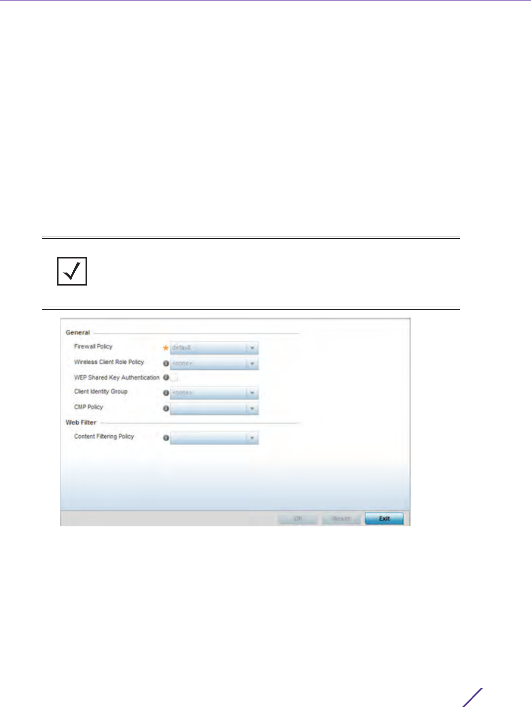
Device Configuration
Wireless Controller and Service Platform System Reference Guide 5 - 203
data protection requirements the profile supports. However, as deployment requirements arise, an individual device
may need some or all of its general security configuration overridden from the profile’s settings.
To configure a profile’s security settings and overrides:
1Select
Devices from the Configuration tab.
The Device Configuration screen displays a list of managed devices or peer controllers, service platforms or
Access Points.
2 Select a target device (by double-clicking it) from amongst those displayed within the Device Configuration
screen.
Devices can also be selected directly from the Device Browser in the lower, left-hand, side of the UI.
3Select
Profile Overrides from the Device menu to expand it into sub menu options.
4Select
Security to expand its sub menu options.
5Select
Settings.
Figure 5-113 Profile Overrides - General Security screen
NOTE: A blue override icon (to the left of a parameter) defines the parameter as
having an override applied. To remove an override go to the Basic Configuration
section of the device and click the Clear Overrides button. This removes all
overrides from the device.

Device Configuration
Wireless Controller and Service Platform System Reference Guide 5 - 204
6 Refer to the General field to assign or override the following:
7Use the Web Filter drop-down menu to select or override the URL Filter configuration applied to this virtual
interface.
Web filtering is used to restrict access to resources on the Internet.
8Select
OK to save the changes or overrides. Select Reset to revert to the last saved configuration.
5.2.9.2 Overriding a Profile’s Certificate Revocation List (CRL) Configuration
Overriding a Profile’s Security Configuration
A certificate revocation list (CRL) is a list of revoked certificates that are no longer valid. A certificate can be
revoked if the certificate authority (CA) had improperly issued a certificate, or if a private-key is compromised. The
most common reason for revocation is the user no longer being in sole possession of the private key.
To define a Certificate Revocation configuration or override:
Firewall Policy Use the drop-down menu to select an existing Firewall Policy to use as
an additional security mechanism with this profile. All devices using this
profile must meet the requirements of the firewall policy to access the
network. A firewall is a mechanism enforcing access control, and is
considered a first line of defense in protecting proprietary information
within the network. The means by which this is accomplished varies, but
in principle, a firewall can be thought of as mechanisms both blocking
and permitting data traffic within the network. If an existing Firewall
policy does not meet your requirements, select the Create icon to create
a new firewall policy that can be applied to this profile. An existing
policy can also be selected and edited as needed using the Edit icon.
Wireless Client Role
Policy
Use the drop-down menu to select a client role policy used to
strategically filter client connections based on a pre-defined set of filter
rules and connection criteria. If an existing Wireless Client Role policy
does not meet your requirements, select the Create icon to create a new
configuration that can be applied to this profile. An existing policy can
also be selected and edited as needed using the Edit icon.
WEP Shared Key
Authentication
Select this option to require devices to use a WEP key to access the
network using this profile. The controller or service platform use the key
algorithm to convert an ASCII string to the same hexadecimal number.
Clients without adapters need to use WEP keys manually configured as
hexadecimal numbers. This option is disabled by default.
Client Identity Group Select the client identity group to apply to this device profile. Client
identity is a set of unique fingerprints used to identify a class of devices.
A Client identity group is a set of client attributes that identify devices
and apply specific permissions and restrictions on them.The information
is used to configure permissions and access rules for that device class
and can assist administrators by applying permissions and rules to
multiple devices simultaneously.
CMP Policy Use the drop down-menu to assign a CMP policy to allow a device to
communicate to a CMP supported CA server, initiate a certificate
request and download the required certificates from the CA server. CMP
supports multiple request options through for device communicating to
a CMP supported CA server. The device can initiate a request for getting
the certificates from the server. It can also auto update the certificates
which are about to expire.
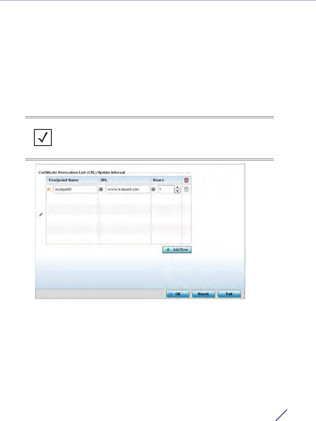
Device Configuration
Wireless Controller and Service Platform System Reference Guide 5 - 205
1Select
Devices from the Configuration tab.
The Device Configuration screen displays a list of managed devices or peer controllers, service platforms or Access
Points within the managed network.
2 Select a target device (by double-clicking it) from amongst those displayed within the Device Configuration
screen.
Devices can also be selected directly from the Device Browser in the lower, left-hand, side of the UI.
3Select
Profile Overrides from the Device menu to expand it into sub menu options.
4Select
Security to expand its sub menu options.
5Select
Certificate Revocation.
Figure 5-114 Profile Overrides - Certificate Revocation screen
6 Select the + Add Row button to add a column within the Certificate Revocation List (CRL) Update Interval table
to quarantine certificates from use in the managed network.
Additionally, a certificate can be placed on hold for a user defined period. If, for instance, a private key was
found and nobody had access to it, its status could be reinstated.
a Provide the name of the trustpoint in question within the Trustpoint Name field. The name cannot exceed 32
characters.
b Enter the resource ensuring the trustpoint’s legitimacy within the URL field.
c Use the spinner control to specify an interval (in hours) after which a device copies a CRL file from an
external server and associates it with a trustpoint.
7Select
OK to save the changes and overrides made within the Certificate Revocation screen. Select Reset to
revert to the last saved configuration.
NOTE: A blue override icon (to the left of a parameter) defines the parameter as
having an override applied. To remove an override go to the Basic Configuration
section of the device and click the Clear Overrides button. This removes all
overrides from the device.
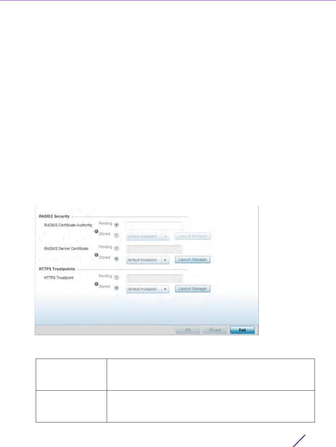
Device Configuration
Wireless Controller and Service Platform System Reference Guide 5 - 206
5.2.9.3 Overriding a Profile’s RADIUS Trustpoint Configuration
Overriding a Profile’s Security Configuration
A RADIUS certificate links identity information with a public key enclosed in the certificate. A certificate authority
(CA) is a network authority that issues and manages security credentials and public keys for message encryption.
The CA signs all digital certificates it issues with its own private key. The corresponding public key is contained
within the certificate and is called a CA certificate.
To define a RADIUS Trustpoint configuration, utilize an existing stored trustpoint or launch the certificate manager
to create a new one:
1Select
Devices from the Configuration tab.
The Device Configuration screen displays a list of managed devices or peer controllers, service platforms or
Access Points within the managed network.
2 Select a target device (by double-clicking it) from amongst those displayed within the Device Configuration
screen.
Devices can also be selected directly from the Device Browser in the lower, left-hand, side of the UI.
3Select
Profile Overrides from the Device menu to expand it into sub menu options.
4Select
Security to expand its sub menu options.
5Select
Trustpoints.
Figure 5-115 Profile Overrides - Trustpoints screen
6 Set the following RADIUS Security certificate settings:
RADIUS Certificate
Authority
Either use the default-trustpoint or select the Stored radio button to
enable a drop-down menu where an existing certificate can be
leveraged. To leverage an existing certificate, select the Launch Manager
button.
RADIUS Server
Certificate
Either use the default-trustpoint or select the Stored radio button to
enable a drop-down menu where an existing certificate/trustpoint can
be used. To leverage an existing trustpoint, select the Launch Manager
button.

Device Configuration
Wireless Controller and Service Platform System Reference Guide 5 - 207
7 Set the following HTTPS Trustpoints:
8Select
OK to save the changes made within the RADIUS Trustpoints screen. Select Reset to revert to the last
saved configuration.
5.2.9.4 Overriding a Profile’s VPN Configuration
Overriding a Profile’s Security Configuration
IPSec VPN provides a secure tunnel between two networked peer devices. Administrators can define which
packets are sent within the tunnel, and how they’re protected. When a tunnelled peer sees a sensitive packet, it
creates a secure tunnel and sends the packet through the tunnel to its remote peer destination.
Tunnels are sets of security associations (SA) between two peers. SAs define the protocols and algorithms applied
to sensitive packets and specify the keying mechanisms used by tunneled peers. SAs are unidirectional and exist in
both the inbound and outbound direction. SAs are established per the rules and conditions of defined security
protocols (AH or ESP).
Use crypto maps to configure IPSec VPN SAs. Crypto maps combine the elements comprising IPSec SAs. Crypto
maps also include transform sets. A transform set is a combination of security protocols, algorithms and other
settings applied to IPSec protected traffic. One crypto map is utilized for each IPSec peer, however for remote VPN
deployments one crypto map is used for all the remote IPSec peers.
Internet Key Exchange (IKE) protocol is a key management protocol standard used in conjunction with IPSec. IKE
enhances IPSec by providing additional features, flexibility, and configuration simplicity for the IPSec standard. IKE
automatically negotiates IPSec SAs, and enables secure communications without time consuming manual pre-
configuration.
To define a profile’s VPN settings:
1Select
Devices from the Configuration tab.
2 Select a target device (by double-clicking it) from amongst those displayed within the Device Configuration
screen.
3Select
Profile Overrides from the Device menu to expand it into sub menu options.
4Expand the Security menu and select VPN.
The profile’s VPN configuration can be set or overridden using either a VPN setup wizard or by manually
configuring the required advanced settings. WiNG provides two (2) wizards providing either minimal or more
thorough administration.
HTTPS Trustpoint Either use the default trustpoint or select the Stored radio button to
enable a drop-down menu where an existing certificate/trustpoint can
be utilized. To use an existing certificate for this device, select the Launch
Manager button. For more information, see Certificate Management.
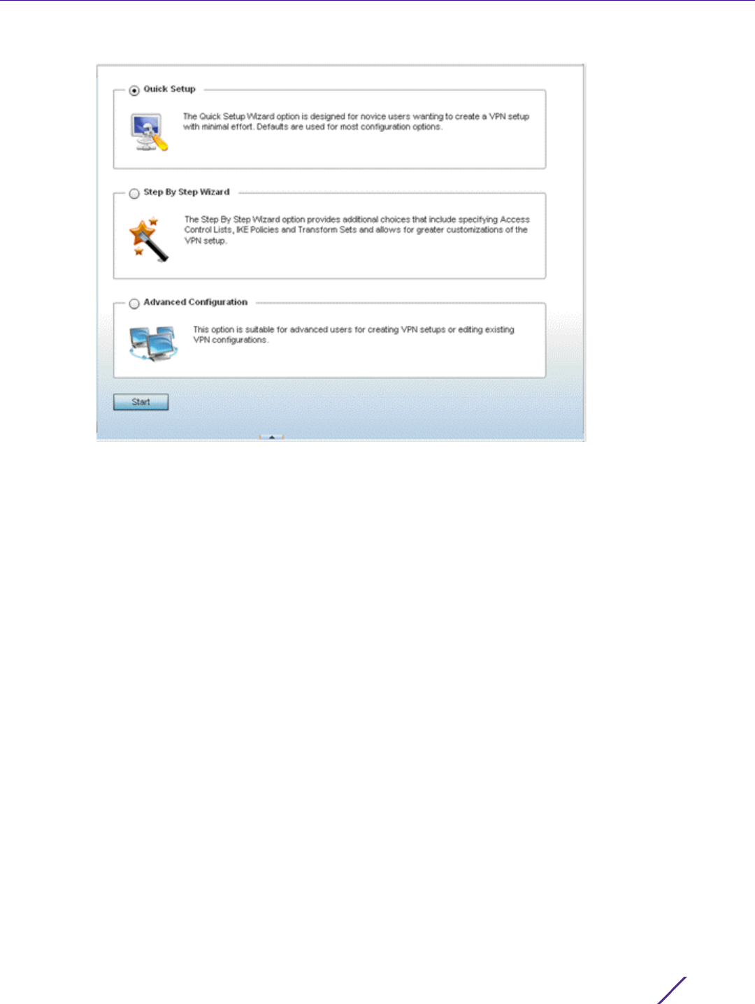
Device Configuration
Wireless Controller and Service Platform System Reference Guide 5 - 208
Figure 5-116 VPN Setup Wizard
•Quick Setup Wizard - Use the quick setup wizard to set a minimum number of basic VPN tunnel values. This
wizard is designed for novice users, and enables them to setup a VPN configuration with minimum effort.
This wizard uses default values for most parameters.
•Step By Step Wizard - Use the step-by-step wizard to create a VPN tunnel using settings updated from their
minimum default values. This wizard is designed for intermediate users who require some VPN
customization.
•Advanced VPN Configuration - The advanced VPN configuration option does not utilize a setup wizard.
Rather, it utilizes and its own screen flow where just about every facet of a VPN tunnel configuration can be
set by a qualified network administrator. For more information, see Setting the Profile’s VPN Configuration
on page 8-168.
5.2.9.4.4 Quick Setup Wizard
The Quick Setup Wizard creates a VPN configuration with minimum administration. Default values are retained for
most parameters.
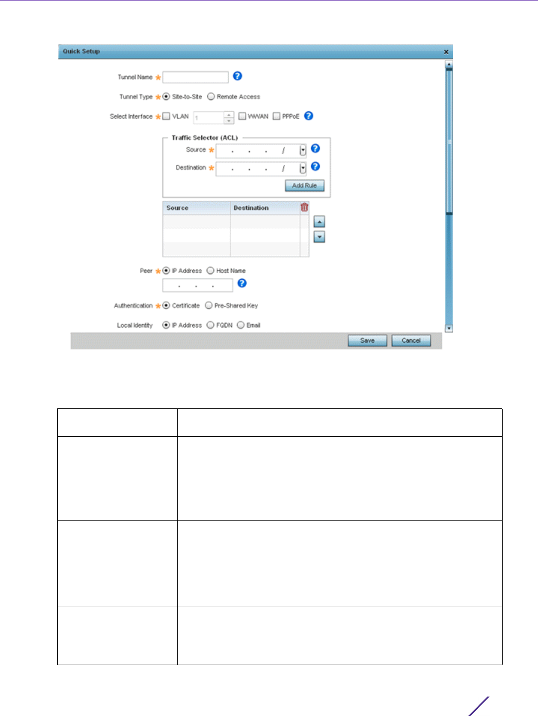
Device Configuration
Wireless Controller and Service Platform System Reference Guide 5 - 209
Figure 5-117 VPN Quick Setup Wizard
1Select Quick Setup from the VPN Wizard screen.
2 Provide the following quick setup information to configure a VPN tunnel:
Tunnel Name Provide a name for the tunnel. Tunnel name identifies the tunnel
uniquely.
Tunnel Type Configure the type of the tunnel. Tunnel can be one of the following
types:
•Site-to-Site – This tunnel provides a secured connection between two
sites (default setting).
•Remote Access – This tunnel provides access to a network to remote
devices.
Select Interface Configure the interface to use for creating the tunnel. The following
options are available:
•VLAN – Configure the tunnel over a Virtual LAN interface. Use the
spinner to configure the VLAN number.
•WWAN – Configure the tunnel over the WAN interface.
•PPPoE – Configure the tunnel over the PPPoE interface.
Traffic Selector (ACL) Configure ACLs that manage the traffic passing through the VPN
tunnel. The following options are available:
•Source – Provide the source network along with its mask
•Destination – Provide the destination network along with its mask.

Device Configuration
Wireless Controller and Service Platform System Reference Guide 5 - 210
3Select
Save to save the VPN quick setup tunnel configuration. To exit without saving, select Cancel.
5.2.9.4.5 Step By Step Wizard
The Step-By-Step wizard creates a VPN connection with more manual configuration than the Quick Setup Wizard.
Use this wizard to manually configure Access Control Lists, IKE Policy, and Transform Sets to customize the VPN
Tunnel.
1 Select the Step-By-Step Wizard option from the VPN screen.
2 Select the Start button.
Peer Configure the peer for this tunnel. The peer device can be specified
either by its hostname or by its IP address.
Authentication Set the authentication used to identify the peers with each other on
opposite ends of the VPN tunnel connection. The following can be
configured:
•Certificate – Use a certificate to authenticate (default value).
•Pre-Shared Key – Use a pre-shared key to authenticate. Enter the
secret key in the space provided for it.
Local Identity Configure the local identity used with this peer configuration for an IKE
exchange with the target VPN IPSec peer. Options include IP Address,
Distinguished Name, FQDN, email and string. The default setting is
string.
Remote Identity Configure the Access Point remote identifier used with this peer
configuration for an IKE exchange with the target VPN IPSec peer.
Options include IP Address, Distinguished Name, FQDN, email and
string. The default setting is string.
IKE Policy Configure the IKE policy to use. IKE is used to exchange authentication
keys. Select from one of the following:
•All – Use any IKE policy (default value).
•IKE1 – Use IKE 1 only
•IKE2 – Use IKE 2 only
Transform Set Configure the transform set used to specify how traffic is protected
within the crypto ACL defining the traffic that needs to be protected.
Select the appropriate traffic set from the drop-down list.
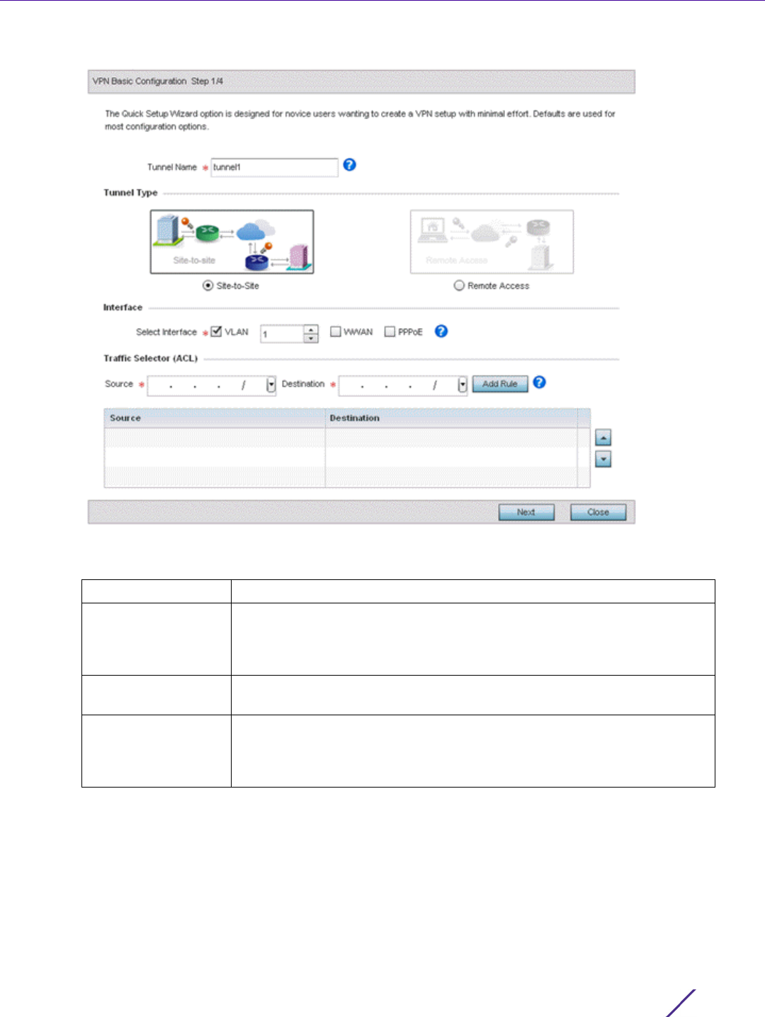
Device Configuration
Wireless Controller and Service Platform System Reference Guide 5 - 211
Figure 5-118 VPN Step-By-Step Wizard - Step 1
3 Set the following VPN values for step 1:
4 Select the Next button to proceed to step 2.
If any of the required values within the step 1 screen are not set properly, the second wizard screen will not
display until they are properly set.
Tunnel Name Provide a name for the tunnel in the Tunnel Name field.
Tunnel Type Select the tunnel type being created. Two types of tunnels can be created.
Site to Site (the default setting) is used to create a tunnel between two
remote sites. Remote Access is used to create a tunnel between an user
device and a network.
Interface Select the interface to use. Interface can be a Virtual LAN (VLAN) or
WWAN or PPPoE depending on the interfaces available on the device.
Traffic Selector This field creates the Access Control List (ACL) that is used to control who
uses the network. Provide the Source and Destination IP address ranges
with their net mask. Click the Add Rule button to add the rule into the
ACL.
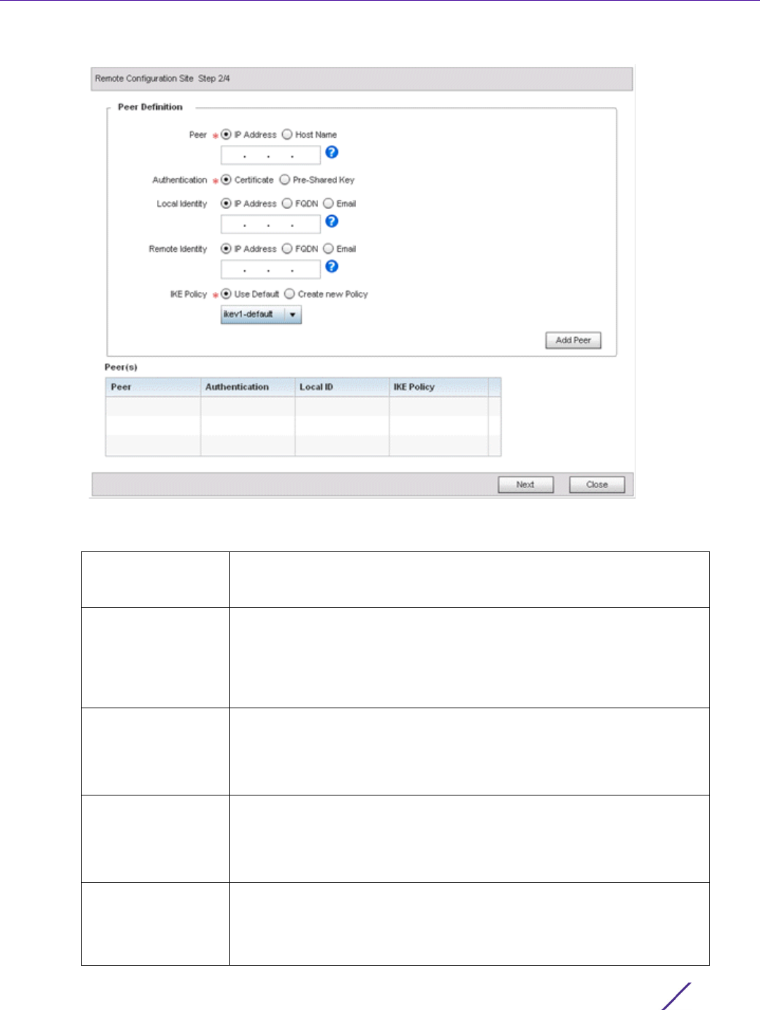
Device Configuration
Wireless Controller and Service Platform System Reference Guide 5 - 212
Figure 5-119 VPN Step-By-Step Wizard - Step 2
5 Set the following VPN quick setup values for step 2:
Peer Select the type of peer for this device when forming a tunnel. Peer
information can be either an IP Address (default value) or hostname.
Provide the IP address or the host name of the peer device.
Authentication Configure how devices authenticate on opposite ends of the tunnel
connection.
•Certificate – The devices use certificates to authenticate with each other
(default value).
•Pre-Shared Key – The devices use pre-shared key to authenticate.
Local Identity Configure the local identity for the VPN tunnel.
•IP Address – The local identity is an IP address (default value).
•FQDN – The local identity is a Fully Qualified Domain Name (FQDN).
•Email – The local identity is an E-mail address.
Remote Identity Configure the remote identity for the VPN tunnel.
•IP Address – The remote identity is an IP address (default value).
•FQDN – The remote identity is a FQDN.
•Email – The remote identity is an E-mail address.
IKE Policy Configure an IKE policy to use when creating this VPN Tunnel. The
following options are available:
•Use Default – Select this option to use the default IKE profiles.
•Create new Policy – Select this option to create a new IKE policy.
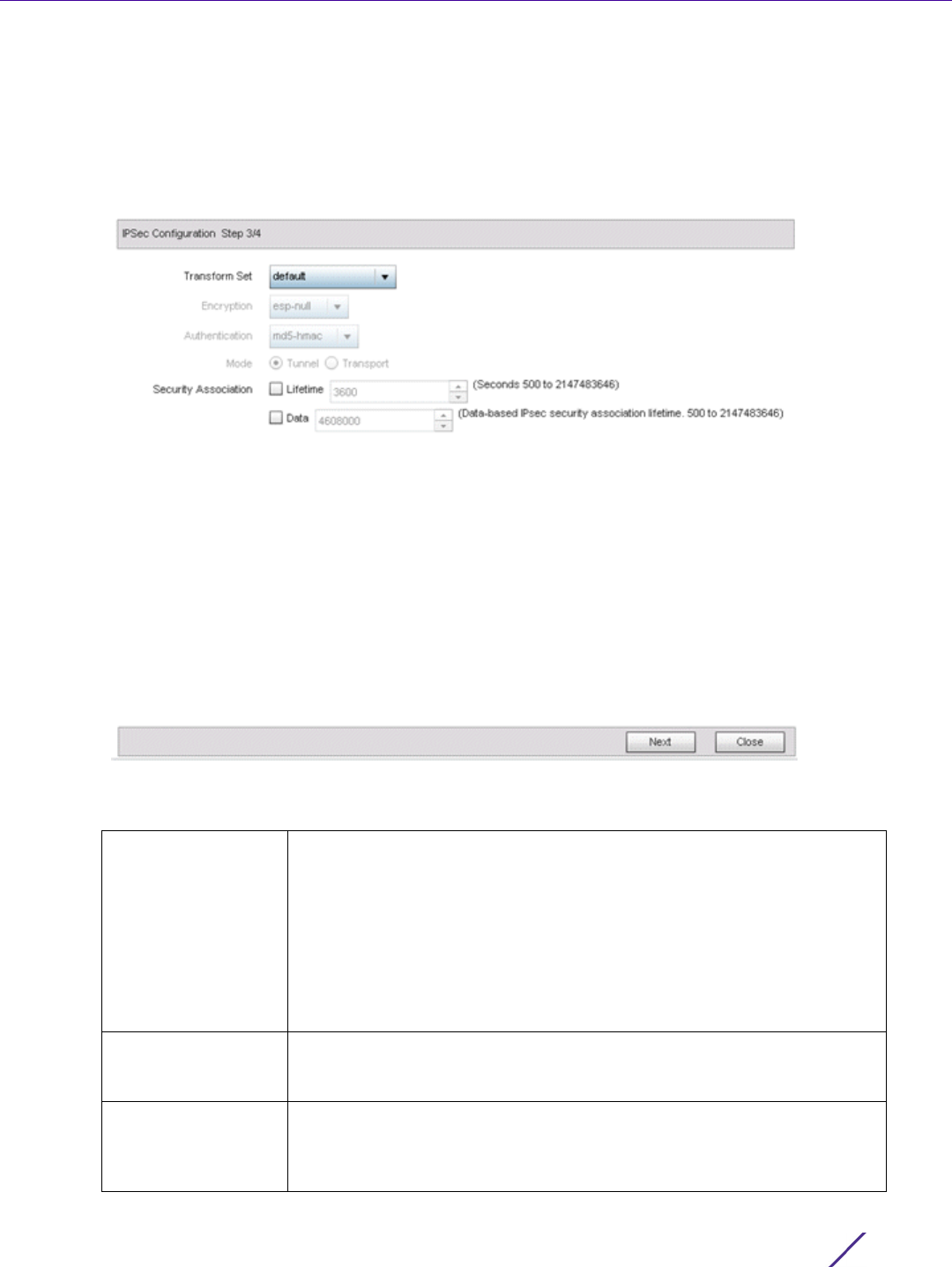
Device Configuration
Wireless Controller and Service Platform System Reference Guide 5 - 213
6 Click the Add Peer button to add the tunnel peer information into the Peer(s) table. This table lists all the peers
set for the VPN Tunnel.
7Select
Next to proceed to the step 3 screen. Use the Back button to go to the previous step.
If any of the required values within the step 2 screen are not set properly, the third wizard screen will not
display until they are properly set.
Figure 5-120 VPN Step-By-Step Wizard - Step 3
8 Set the following IPSec VPN values for step 3:
Transform Set The transform set is a set of configurations for creating the VPN tunnel
and imposes a security policy on the tunnel. Primarily, the transform set
comprises the following:
•Encryption – The encryption used for creating the tunnel.
•Authentication – The authentication used to identify tunnel peers
•Mode – The mode of the tunnel. This is the tunnel’s operational mode.
From the drop-down, select any pre-configured Transform Set or select
Create New Policy to create a new transform set.
Encryption This field is enabled when Create New Policy is selected in Transform Set
field. This is the encryption used on data traversing through the tunnel.
Select either esp-null, des, 3des, aes, aes-192 or aes-256.
Authentication This field is enabled when Create New Policy is selected in Transform Set
field. This is how peers authenticate as the source of the packet to the
other peers after a VPN tunnel has been created. Select either MD5, SHA,
SHA256 or AES-XCBC-HMAC-128.
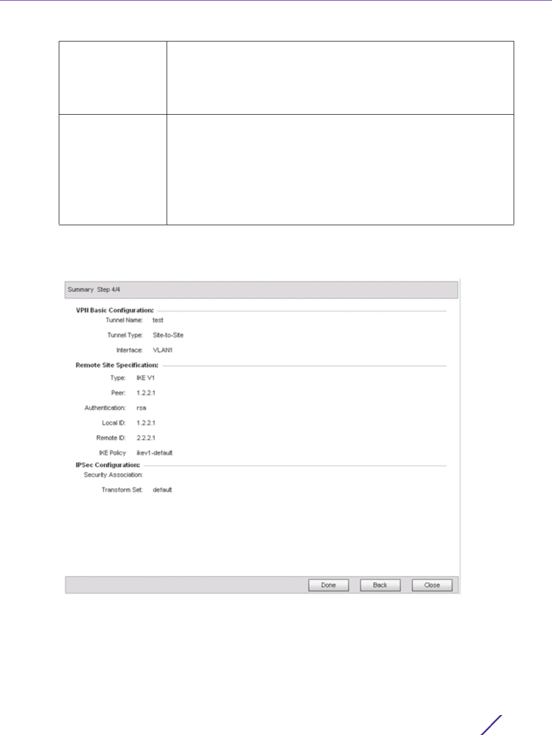
Device Configuration
Wireless Controller and Service Platform System Reference Guide 5 - 214
9Select
Next to proceed to the fourth configuration screen. Use the Back button to navigate to the previous step.
If any of the required values within the step 3 screen are not set properly, the fourth wizard screen will not
display until they are properly set.
Figure 5-121 VPN Step-By-Step Wizard - Step 4
10 Review the configuration and select Done initiate the creation of the VPN tunnel. Use the Back button to
navigate to the previous screen. Select Close to close the wizard without creating a VPN Tunnel.
5.2.9.4.6 Advanced VPN Configuration
The advanced VPN configuration option does not utilize a setup wizard. Rather, it utilizes and its own screen flow
where just about every facet of a VPN tunnel configuration can be set by a qualified network administrator.
Mode This field is enabled when Create New Policy is selected in Transform Set
field. This indicates how packets are transported through the tunnel.
•Tunnel – Use this mode when the Tunnel is between two routers or servers.
•Transport – Use this mode when the Tunnel is created between a client
and a server.
Security Association Configures the lifetime of a security association (SA). Keys and SAs
should be periodically renewed to maintain security of the tunnel. The
field defines the parameters that set the lifetime of a security association.
•Lifetime – Set the duration (in seconds) after which the keys should be
changed. Set a value from 500-2,147,483,646 seconds.
•Data – This is the amount of data in KBs the key can use. The key is
changed after this quantity of data has be encrypted/decrypted. Set a
value from 500-2,147,483,646 KBs.
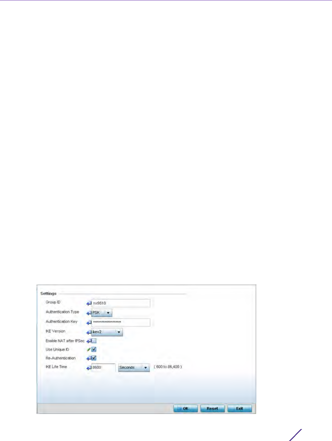
Device Configuration
Wireless Controller and Service Platform System Reference Guide 5 - 215
For detailed information on creating a VPN tunnel configuration, refer to Setting the Profile’s VPN Configuration on
page 8-168.
5.2.9.5 Overriding a Profile’s Auto IPSec Tunnel Configuration
Overriding a Profile’s Security Configuration
Auto IPSec tunneling provides a secure tunnel between two networked peer controllers or service platforms and
associated Access Points which are within a range of valid IP addresses. Administrators can define which packets
are sent within the tunnel, and how they’re protected. When a tunnelled peer sees a sensitive packet, it creates a
secure tunnel and sends the packet through the tunnel to its remote peer destination or associated Access Point
Tunnels are sets of security associations (SA) between two peers. SAs define the protocols and algorithms applied
to sensitive packets and specify the keying mechanisms used by tunnelled peers. SAs are unidirectional and exist
in both the inbound and outbound direction. SAs are established per the rules and conditions of defined security
protocols (AH or ESP).
Internet Key Exchange (IKE) protocol is a key management protocol standard used in conjunction with IPSec. IKE
enhances IPSec by providing additional features, flexibility, and configuration simplicity for the IPSec standard. IKE
enables secure communications without time consuming manual pre-configuration for auto IPSec tunneling.
To define an Auto IPSec Tunnel configuration or override that can be applied to a profile:
1Select
Devices from the Configuration tab.
The Device Configuration screen displays a list of managed devices or peer controllers, service platforms or
Access Points.
2 Select a target device (by double-clicking it) from amongst those displayed within the Device Configuration
screen.
Devices can also be selected directly from the Device Browser in the lower, left-hand, side of the UI.
3Select
Profile Overrides from the Device menu to expand it into sub menu options.
4Select
Security to expand its sub menu options.
5Select
Auto IPSec Tunnel.
Figure 5-122 Profile Overrides - Auto IPSec Tunnel screen

Device Configuration
Wireless Controller and Service Platform System Reference Guide 5 - 216
The Settings field lists those Auto IPSec tunnel policies created thus far. Any of these policies can be selected
and applied to a profile.
6Select
OK to save the changes made to the auto IPSec tunnel configuration. Select Reset to revert to the last
saved configuration.
5.2.9.6 Overriding a Profile’s NAT Configuration
Overriding a Profile’s Security Configuration
Network Address Translation (NAT) is a technique to modify network address information within IP packet headers
in transit. This enables mapping one IP address to another to protect wireless controller managed network address
credentials. With typical deployments, NAT is used as an IP masquerading technique to hide private IP addresses
behind a single, public facing, IP address.
Additionally, NAT is a process of modifying network address information in IP packet headers while in transit
across a traffic routing device for the purpose of remapping one IP address to another. In most deployments NAT
is used in conjunction with IP masquerading which hides RFC1918 private IP addresses behind a single public IP
address.
NAT can provide a profile outbound Internet access to wired and wireless hosts connected to either an Access
Point or a wireless controller. Many-to-one NAT is the most common NAT technique for outbound Internet access.
NOTE: A blue override icon (to the left of a parameter) defines the parameter as
having an override applied. To remove an override go to the Basic Configuration
section of the device and click the Clear Overrides button. This removes all
overrides from the device.
Group ID Define a 1 - 64 character identifier for an IKE exchange supporting auto
IPSec tunnel secure peers.
Authentication Type Use the drop-down menu to select either RSA or PSK (Pre Shared Key)
as the authentication type for secure peer authentication on the auto
IPSec secure tunnel. Rivest, Shamir, and Adleman (RSA) is an algorithm
for public key cryptography. It’s the first algorithm known to be suitable
for signing, as well as encryption. The default setting is RSA.
Authentication Key Enter the 8 - 21 character shared key (password) used for auto IPSec
tunnel secure peer authentication.
IKE Version Use the drop-down menu to select the IKE version used for auto IPSec
tunnel secure authentication with the IPSec gateway. IKEv2 is the
default setting.
Enable NAT after IPSec Select the checkbox to enable internal source port NAT on the auto
IPSec secure tunnel.
Use Unique ID Select this option to use a unique ID with auto IPSec secure
authentication for the IPSec remote gateway (appending the MiNT ID).
This setting is disabled by default.
Re-Authentication Select this option to re-authenticate the key on a IKE rekey. This setting
is enabled by default.
IKE Life Time Set a lifetime in either Seconds (600 - 86,400), Minutes (10 - 1,440),
Hours (1 - 24) or Days (1) for IKE security association duration. The
default setting is 8600 seconds.
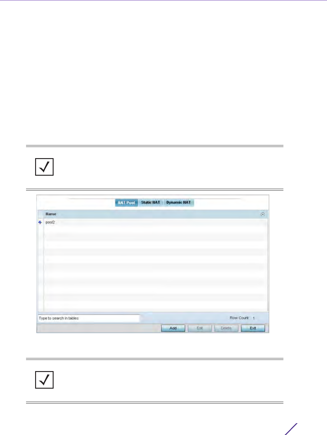
Device Configuration
Wireless Controller and Service Platform System Reference Guide 5 - 217
Many-to-one NAT allows an Access Point or wireless controller to translate one or more internal private IP
addresses to a single, public facing, IP address assigned to a 10/100/1000 Ethernet port or 3G card.
To define a NAT configuration or override that can be applied to a profile:
1Select
Devices from the Configuration tab.
The Device Configuration screen displays a list of managed devices or peer controllers, service platforms or
Access Points within the managed network.
2 Select a target device (by double-clicking it) from amongst those displayed within the Device Configuration
screen.
Devices can also be selected directly from the Device Browser in the lower, left-hand, side of the UI.
3Select
Profile Overrides from the Device menu to expand it into sub menu options.
4Select
Security to expand its sub menu options.
5Select
NAT.
Figure 5-123 Profile Overrides - NAT Pool screen
The NAT Pool screen displays by default. The NAT Pool screen lists those NAT policies created thus far. Any of
these policies can be selected and applied to a profile.
NOTE: A blue override icon (to the left of a parameter) defines the parameter as
having an override applied. To remove an override go to the Basic Configuration
section of the device and click the Clear Overrides button. This removes all
overrides from the device.
NOTE: A blue override icon (to the left of a parameter) defines the parameter as
having an override applied. To remove an override go to the Basic Configuration
section of the device and click the Clear Overrides button. This removes all
overrides from the device.
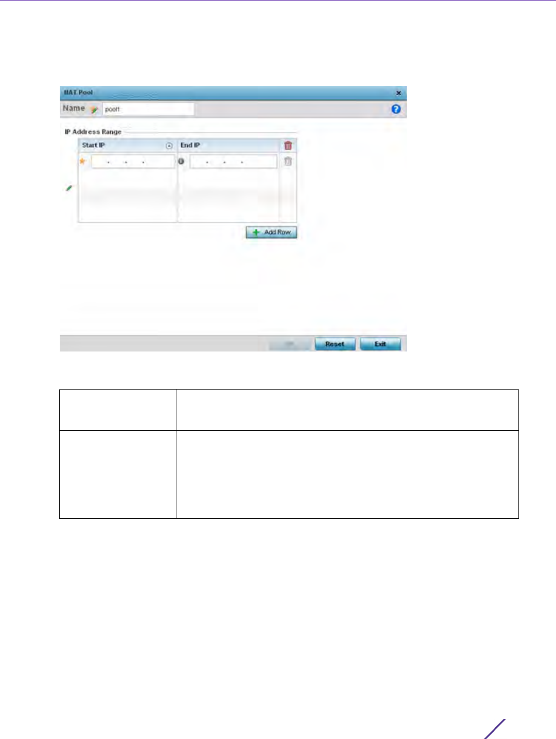
Device Configuration
Wireless Controller and Service Platform System Reference Guide 5 - 218
6Select
Add to create a new NAT policy that can be applied to a profile. Select Edit to modify or override the
attributes of a existing policy or select Delete to remove obsolete NAT policies from the list of those available to
a profile.
Figure 5-124 NAT Pool screen
7 If adding a new NAT policy or editing the configuration of an existing policy, define the following parameters:
8 Select the + Add Row button as needed to append additional rows to the IP Address Range table.
9Select
OK to save the changes or overrides made to the profile’s NAT Pool configuration. Select Reset to revert
to the last saved configuration.
10 Select the Static NAT tab.
The Source tab displays by default and lists existing static NAT configurations. Existing static NAT
configurations are not editable, but new configurations can be added or existing ones deleted as they become
obsolete.
Static NAT creates a permanent, one-to-one mapping between an address on an internal network and a
perimeter or external network. To share a Web server on a perimeter interface with the Internet, use static
address translation to map the actual address to a registered IP address. Static address translation hides the
actual address of the server from users on insecure interfaces. Casual access by unauthorized users becomes
much more difficult. Static NAT requires a dedicated address on the outside network for each host.
Name If adding a new NAT policy, provide a name to help distinguish it from
others with similar configurations. The length cannot exceed 64
characters.
IP Address Range Define a range of IP addresses that are hidden from the public Internet.
NAT modifies network address information in the defined IP range while
in transit across a traffic routing device. NAT only provides IP address
translation and does not provide a firewall. A branch deployment with
NAT by itself will not block traffic from being potentially routed through
a NAT device. Consequently, NAT should be deployed with a stateful
firewall.
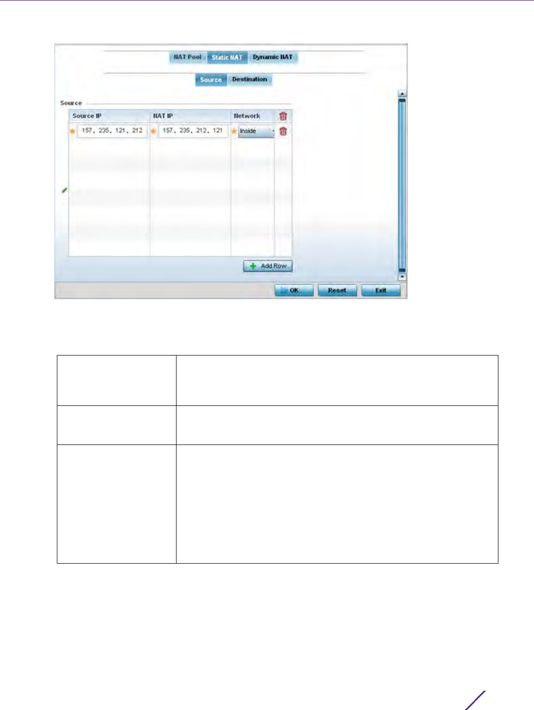
Device Configuration
Wireless Controller and Service Platform System Reference Guide 5 - 219
Figure 5-125 Profile Overrides - Static NAT screen
11 Select + Add Row to create a new static NAT configuration.
12 Set or override the following Source configuration parameters:
13 Select the Destination tab to view destination NAT configurations and define packets passing through the NAT
on the way back to the managed LAN are searched against to the records kept by the NAT engine. The
destination IP address is changed back to the specific internal private class IP address to reach the LAN over
the managed network.
Source IP Enter the local address used at the origination of the static NAT
configuration. This address (once translated) is not exposed to the
outside world when the translation address is used to interact with the
remote destination.
NAT IP Enter the IP address of the matching packet to the specified value. The
IP address modified can be either source or destination based on the
direction specified.
Network Select Inside or Outside NAT as the network direction. Select Inside to
create a permanent, one-to-one mapping between an address on an
internal network and a perimeter or external network. To share a Web
server on a perimeter interface with the Internet, use static address
translation to map the actual address to a registered IP address. Static
address translation hides the actual address of the server from users
on insecure interfaces. Casual access by unauthorized users becomes
much more difficult. Static NAT requires a dedicated address on the
outside network for each host. Inside NAT is the default setting.Inside
is the default setting.
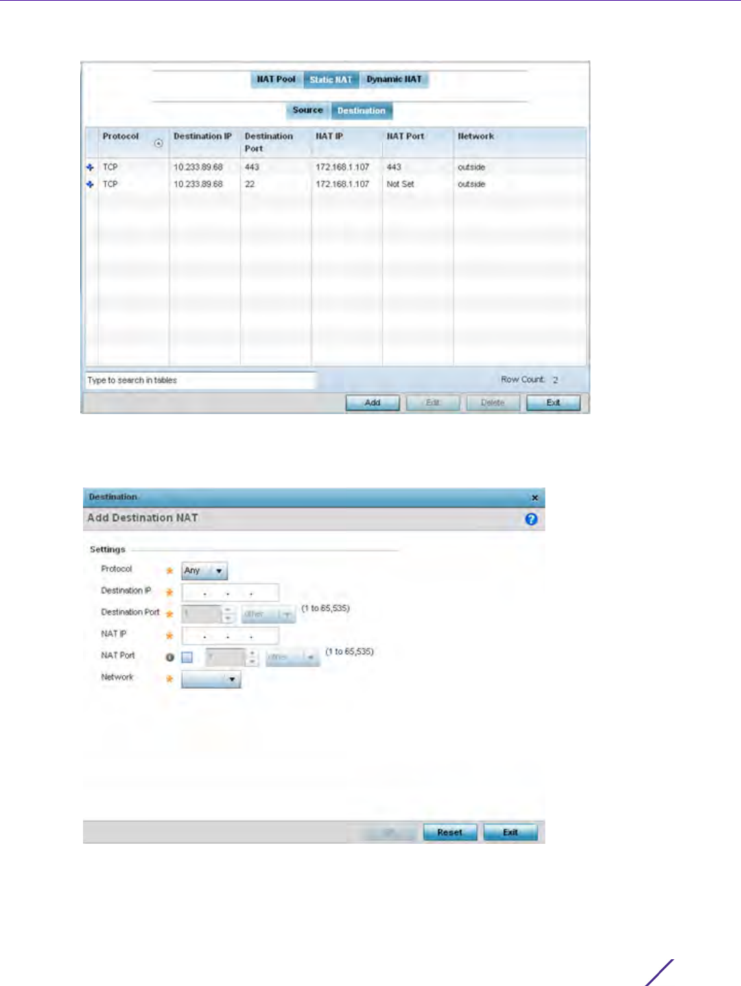
Device Configuration
Wireless Controller and Service Platform System Reference Guide 5 - 220
Figure 5-126 NAT Destination screen
14 Select Add to create a new NAT destination configuration or Delete to permanently remove a NAT destination.
Existing NAT destinations cannot be edited.
Figure 5-127 NAT Destination Add screen
15 Set or override the following Destination configuration parameters:
Static NAT creates a permanent, one-to-one mapping between an address on an internal network and a
perimeter or external network. To share a Web server on a perimeter interface with the Internet, use static
address translation to map the actual address to a registered IP address. Static address translation hides the

Device Configuration
Wireless Controller and Service Platform System Reference Guide 5 - 221
actual address of the server from users on insecure interfaces. Casual access by unauthorized users becomes
much more difficult. Static NAT requires a dedicated address on the outside network for each host.
16 Select OK to save the changes or overrides made to the static NAT configuration. Select Reset to revert to the
last saved configuration.
17 Select the Dynamic NAT tab.
Dynamic NAT configurations translate the IP address of packets going out from one interface to another
interface based on configured conditions. Dynamic NAT requires packets be switched through a NAT router to
generate translations in the translation table.
Protocol Select the protocol for use with static translation (TCP, UDP and Any
are available options). TCP is a transport layer protocol used by
applications requiring guaranteed delivery. It’s a sliding window
protocol handling both time outs and retransmissions. TCP establishes
a full duplex virtual connection between two endpoints. Each endpoint
is defined by an IP address and a TCP port number. The User Datagram
Protocol (UDP) offers only a minimal transport service, non-guaranteed
datagram delivery, and provides applications direct access to the
datagram service of the IP layer. UDP is used by applications not
requiring the level of service of TCP, or are using communications
services (multicast or broadcast delivery) not available from TCP. The
default setting is Any.
Destination IP Enter the local address used at the (source) end of the static NAT
configuration. This address (once translated) is not exposed to the
outside world when the translation address is used to interact with the
remote destination.
Destination Port Use the spinner control to set the local port number used at the
(source) end of the static NAT configuration. The default value is port 1.
NAT IP Enter the IP address of the matching packet to the specified value. The
IP address modified can be either source or destination based on the
direction specified.
NAT Port Enter the port number of the matching packet to the specified value.
This option is valid only if the direction specified is destination.
Network Select Inside or Outside NAT as the network direction. Inside is the
default setting.

Device Configuration
Wireless Controller and Service Platform System Reference Guide 5 - 222
Figure 5-128 Profile Overrides - Dynamic NAT screen
18 Refer to the following to determine whether a new Dynamic NAT configuration requires creation, edit or
deletion:
19 Select Add to create a new Dynamic NAT configuration, Edit to modify or override an existing configuration or
Delete to permanently remove a configuration.
Source List ACL Lists an ACL name to define the packet selection criteria for the NAT
configuration. NAT is applied only on packets which match a rule
defined in the access list. These addresses (once translated) are not
exposed to the outside world when the translation address is used to
interact with the remote destination.
Network Displays Inside or Outside NAT as the network direction for the
dynamic NAT configuration.
Interface Lists the VLAN (from 1 - 4094) used as the communication medium
between the source and destination points within the NAT
configuration.
Overload Type Displays the Overload Type utilized when several internal addresses are
NATed to only one or a few external addresses. Options include NAT
Pool, One Global Address and Interface IP Address. Interface IP Address
is the default setting.
NAT Pool Displays the name of an existing NAT pool used with the dynamic NAT
configuration.
Overload IP If One Global IP Address is selected as the Overload Type, define an IP
address used a filter address for the IP ACL rule.
ACL Precedence Lists the administrator assigned priority set for the listed source list
ACL. The lower the value listed the higher the priority assigned to these
ACL rules.
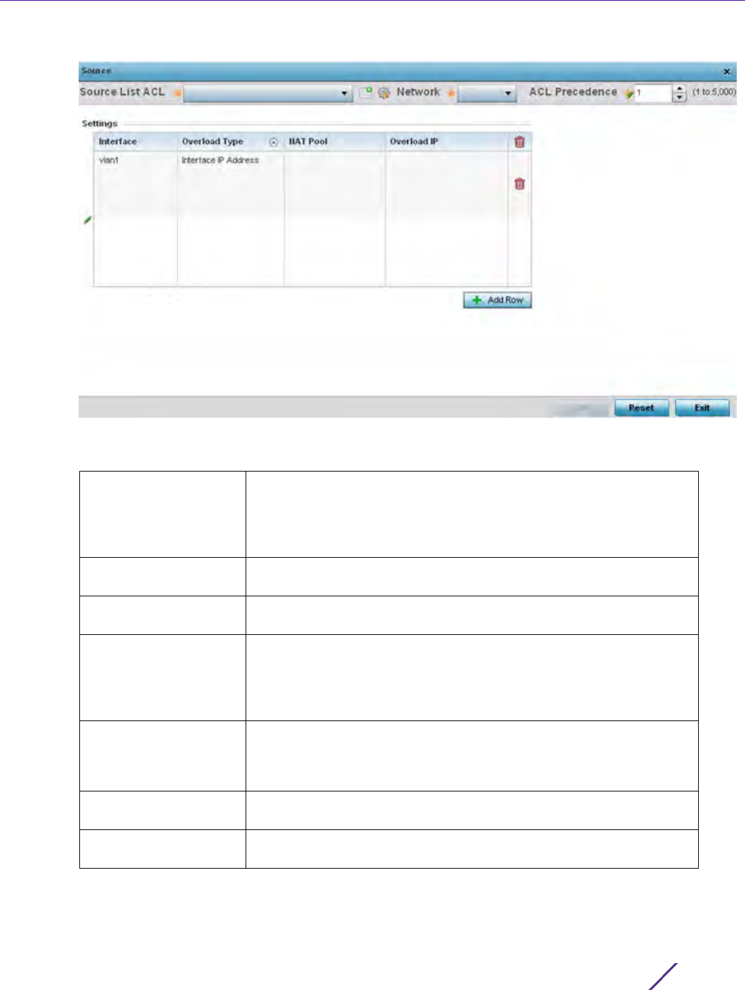
Device Configuration
Wireless Controller and Service Platform System Reference Guide 5 - 223
Figure 5-129 Dynamic NAT Add screen
20 Set or override the following to define the Dynamic NAT configuration:
21 Select OK to save the changes or overrides made to the dynamic NAT configuration. Select Reset to revert to
the last saved configuration.
Source List ACL Use the drop-down menu to select an ACL name to define the packet
selection criteria for NAT. NAT is applied only to packets which match a
rule defined in the access list. These addresses (once translated) are
not exposed to the outside world when the translation address is used
to interact with a remote destination.
Network Select Inside or Outside NAT as the network direction for the dynamic
NAT configuration. Inside is the default setting.
ACL Precedence Set the priority (from 1 - 5000) for the source list ACL. The lower the
value, the higher the priority assigned to these ACL rules.
Interface Use the drop-down menu to select the wireless WAN or VLAN ID
(1 - 4094) used as the communication medium between the source and
destination points within the NAT configuration. Ensure the VLAN
selected represents the intended network traffic within the NAT
supported configuration. VLAN1 is available by default.
Overload Type Define the Overload Type utilized when several internal addresses are
NATed to only one or a few external addresses. Options include NAT
Pool, One Global Address and Interface IP Address. Interface IP Address
is the default setting.
NAT Pool Provide the name of an existing NAT pool for use with the dynamic
NAT configuration.
Overload IP If One Global IP Address is selected as the Overload Type, define an IP
address used a filter address for the IP ACL rule.

Device Configuration
Wireless Controller and Service Platform System Reference Guide 5 - 224
5.2.9.7 Overriding a Profile’s Bridge NAT Configuration
Overriding a Profile’s Security Configuration
Use Bridge NAT to manage Internet traffic originating at a remote site. In addition to traditional NAT functionality,
Bridge NAT provides a means of configuring NAT for bridged traffic through an access point. NAT rules are applied
to bridged traffic through the access point, and matching packets are NATed to the WAN link instead of being
bridged on their way to the router.
Using Bridge NAT, a tunneled VLAN (extended VLAN) is created between the NoC and a remote location. When a
remote client needs to access the Internet, Internet traffic is routed to the NoC, and from there routed to the
Internet. This increases the access time for the end user on the client.
To resolve latency issues, Bridge NAT identifies and segregates traffic heading towards the NoC and outwards
towards the Internet. Traffic towards the NoC is allowed over the secure tunnel. Traffic towards the Internet is
switched to a local WLAN link with access to the Internet.
To define a NAT configuration or override that can be applied to a profile:
1Select
Devices from the Configuration tab.
The Device Configuration screen displays a list of managed devices or peer controllers, service platforms or Access
Points.
2 Select a target device (by double-clicking it) from amongst those displayed within the Device Configuration
screen.
Devices can also be selected directly from the Device Browser in the lower, left-hand, side of the UI.
3Select
Profile Overrides from the Device menu to expand it into sub menu options.
4Select
Security to expand its sub menu options.
5Select
Bridge NAT.
NOTE: A blue override icon (to the left of a parameter) defines the parameter as
having an override applied. To remove an override go to the Basic Configuration
section of the device and click the Clear Overrides button. This removes all
overrides from the device.

Device Configuration
Wireless Controller and Service Platform System Reference Guide 5 - 225
Figure 5-130 Security Bridge NAT screen
6 Review the following Bridge NAT configurations to determine whether a new Bridge NAT configuration requires
creation or an existing configuration modified or removed.
7Select
Add to create a new Bridge VLAN configuration, Edit to modify an existing configuration or Delete to
remove a configuration.
Access List Displays the access list applying IP address access/deny permission
rules to the Bridge NAT configuration.
Interface Lists the communication medium (outgoing layer 3 interface) between
source and destination points. This is either the Access Point’s pppoe1
or wwan1 interface or the VLAN used as the redirection interface
between the source and destination.
NAT Pool Lists the names of existing NAT pools used with the Bridge NAT
configuration. This displays only when Overload Type is NAT Pool.
Overload IP Lists the address used globally for numerous local addresses.
Overload Type Define the overload type utilized when several internal addresses are
NATed to only one or a few external addresses. Set as either NAT Pool,
One Global Address or Interface IP Address.
ACL Precedence Lists the administrator assigned priority set for the ACL. The lower the
value listed the higher the priority assigned to these ACL rules.
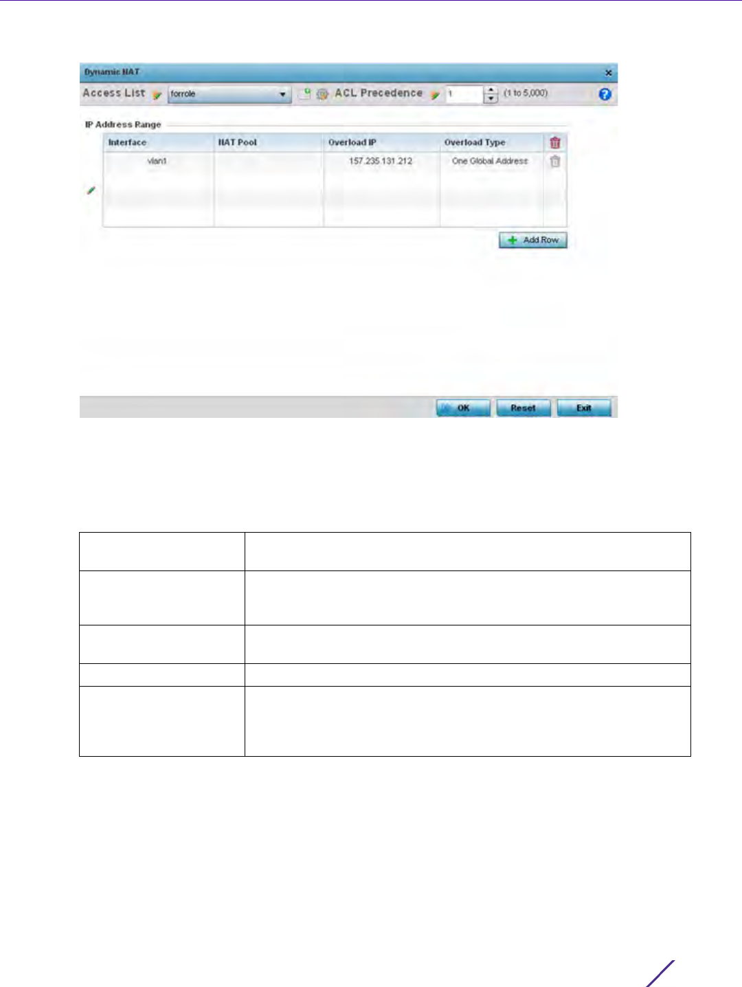
Device Configuration
Wireless Controller and Service Platform System Reference Guide 5 - 226
Figure 5-131 Security Source Dynamic NAT screen
8 Select the ACL whose IP rules are applied to the policy based forwarding rule. A new ACL can be defined by
selecting the Create icon, or an existing set of IP ACL rules can be modified by selecting the Edit icon.
9 Use the IP Address Range table to configure IP addresses and address ranges that can used to access the
Internet.
10 Select + Add Row to set the interface, overload and NAT pool settings for the Bridge NAT configuration.
ACL Precedence Set the priority (from 1 - 5000) for the ACL. The lower the value, the
higher the priority assigned to these ACL rules.
Interface Lists the outgoing layer 3 interface on which traffic is re-directed. The
interface can be an Access Point wwan or pppoe interface. Traffic can
also be redirected to a designated VLAN.
NAT Pool Displays the NAT pool used by this Bridge NAT entry. A value is only
displayed only when Overload Type has been set to NAT Pool.
Overload IP Lists the single global address supporting numerous local addresses.
Overload Type Lists the overload type utilized when several internal addresses are
NATed to only one or a few external addresses. Options include NAT
Pool, One Global Address and Interface IP Address. Interface IP
Address is the default setting.
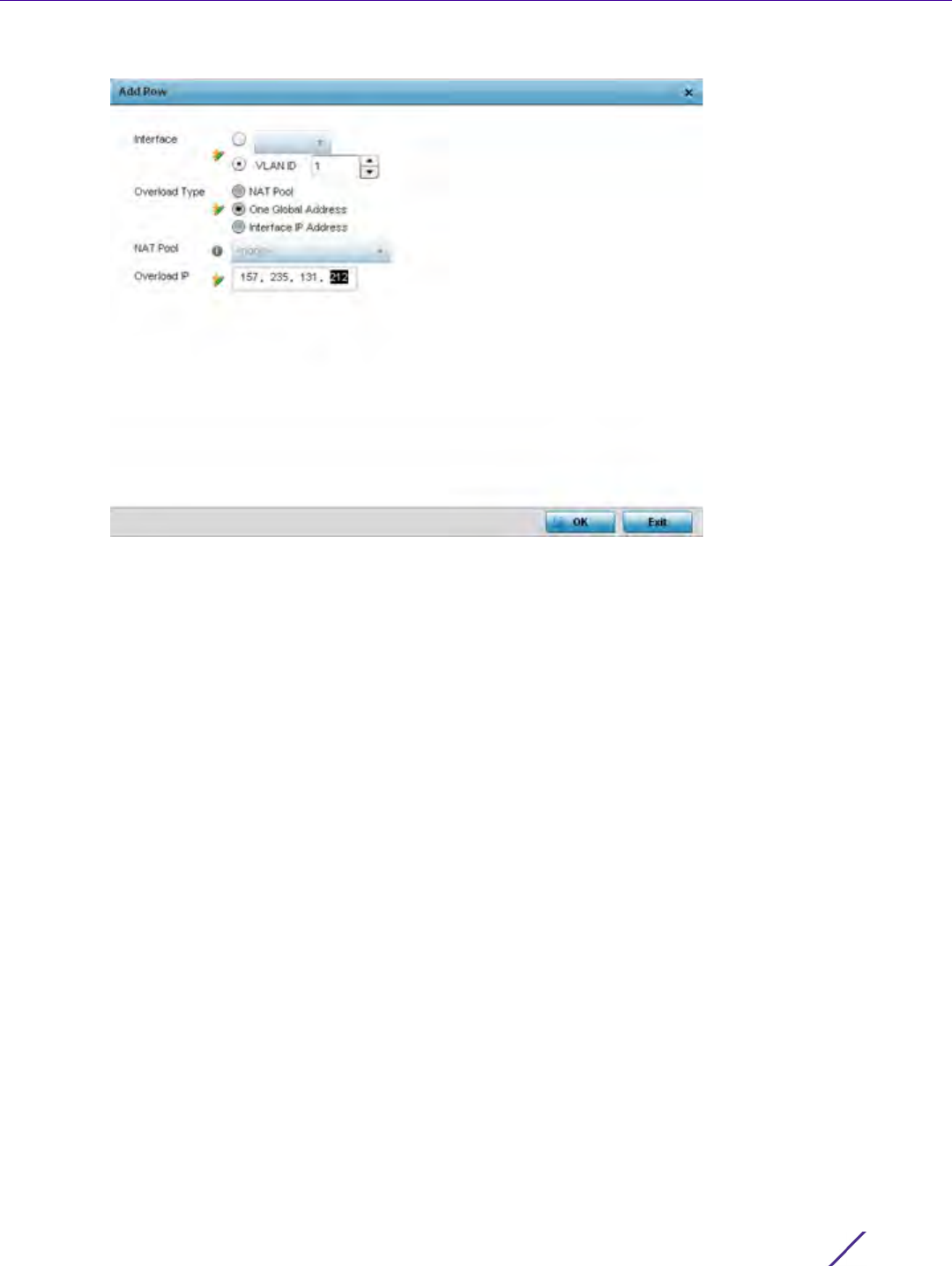
Device Configuration
Wireless Controller and Service Platform System Reference Guide 5 - 227
Figure 5-132 Security Source Dynamic NAT screen
11 Select OK to save the changes made within the Add Row and Source Dynamic NAT screen. Select Reset to
revert to the last saved configuration.
5.2.9.8 Overriding a Profile’s Application Visibility Settings
Overriding a Profile’s Security Configuration
Deep Pocket Inspection (DPI) is an advanced packet analysis technique, which analyzes packet and packet content
headers to determine the nature of network traffic. When DPI is enabled, packets of all flows are subjected to DPI
to get accurate results. DPI identifies applications (such as, Netflix, Twitter, Facebook, etc.) and extracts metadata
(such as, host name, server name, TCP-RTT, etc.) for further use by the WiNG firewall.
To configure a profile’s application visibility settings and overrides:
1Select
Devices from the Configuration tab.
The Device Configuration screen displays a list of managed devices or peer controllers, service platforms or
Access Points.
2 Select a target device (by double-clicking it) from amongst those displayed within the Device Configuration
screen.
Devices can also be selected directly from the Device Browser in the lower, left-hand, side of the UI.
3Select
Profile Overrides from the Device menu to expand it into sub menu options.
4Select
Security to expand its sub menu options.
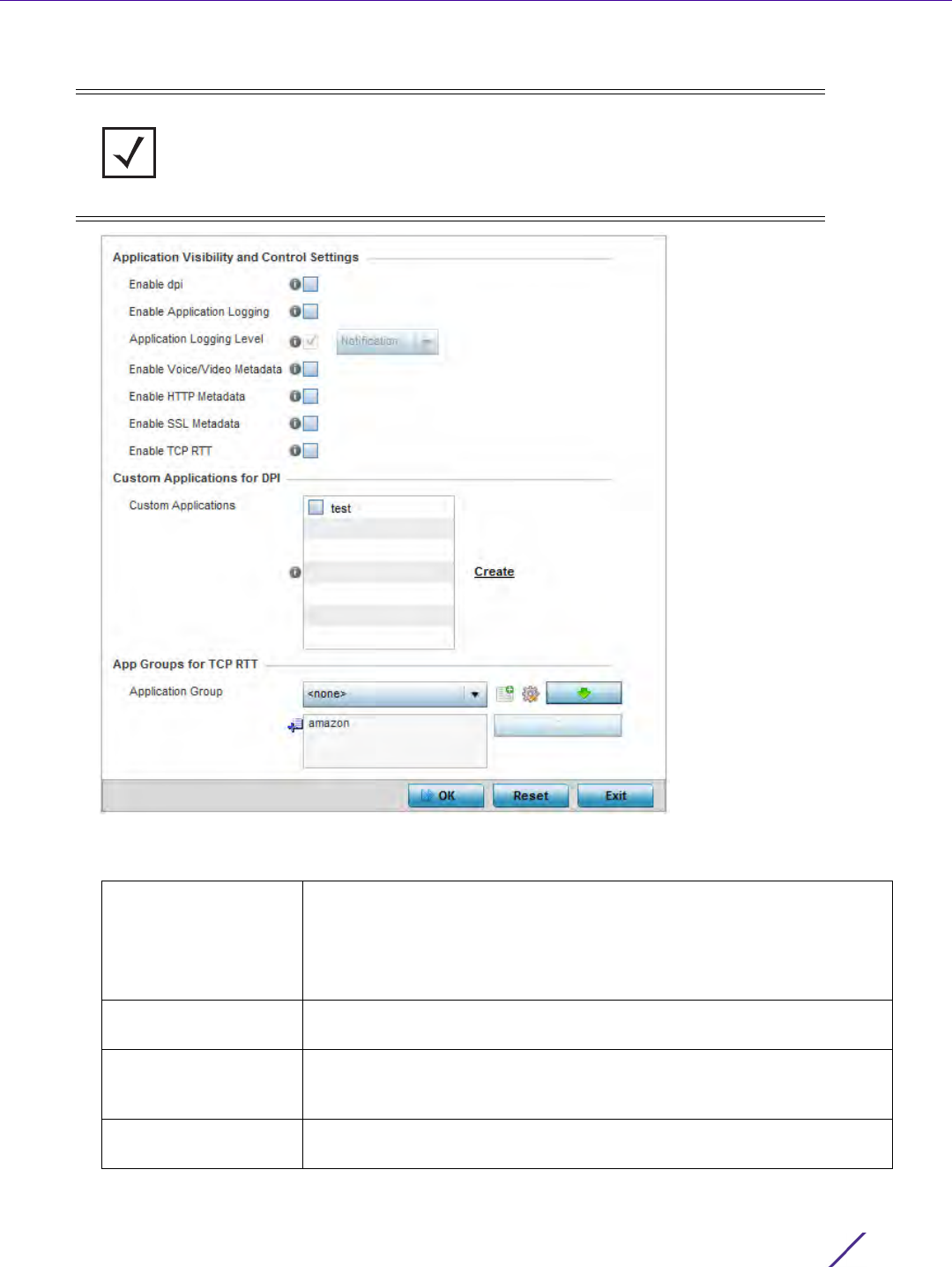
Device Configuration
Wireless Controller and Service Platform System Reference Guide 5 - 228
5Select
Application Visibility.
Figure 5-133 Profile Overrides - Application Visibility screen
6 Refer the following Application Visibility and Control Settings:
NOTE: A blue override icon (to the left of a parameter) defines the parameter as
having an override applied. To remove an override go to the Basic Configuration
section of the device and click the Clear Overrides button. This removes all
overrides from the device.
Enable dpi Enable this setting to provide deep-packet inspection.
When enabled, network flows are inspected at a granular level to identify
applications (such as, Netflix, Twitter, Facebook, etc.) and extract
metadata (such as, host name, server name, TCP-RTT, etc.) for further
use by the WiNG firewall.
Enable Applications
Logging
Select this option to enable event logging for DPI application
recognition. This setting is disabled by default.
Application Logging
Level
If enabling DPI application recognition event logging, set the logging
level. Severity levels include Emergency, Alert, Critical, Errors, Warning,
Notice, Info and Debug. The default logging level is Notification.
Enable Voice/Video
Metadata
Select this option to enable the metadata extraction from voice and
video classified flows. The default setting is disabled.

Device Configuration
Wireless Controller and Service Platform System Reference Guide 5 - 229
7Review the Custom Applications for DPI field to select the custom applications available for this device profile.
For information on creating custom applications and their categories, see Application on page 7-58.
8 If enabling TCP-RTT metadata collection, in the App Groups for TCP RTT field, specify the application groups for
which TCP-RTT metadata collection is to be enabled. Select the Application Groups from the drop-down menu
and use the green, down arrow to move the selection to the box below. Note, you can add maximum of 8
(eight) groups to the list. If the desired application group is not available, select the Create icon to define a new
application group configuration or select the Edit icon to modify an existing application group. For information
on creating custom application groups, see Application on page 7-58.
9Select
OK to save the changes or overrides. Select Reset to revert to the last saved configuration.
5.2.9.9 Overriding a Profile’s VRRP Configuration
Profile Overrides
A default gateway is a critical resource for connectivity. However, it’s prone to a single point of failure. Thus,
redundancy for the default gateway is required by the access point. If WAN backhaul is available, and a router
failure occurs, then the Access Point should act as a router and forward traffic on to its WAN link.
Define an external Virtual Router Redundancy Protocol (VRRP) configuration when router redundancy is required
in a wireless network requiring high availability.
The election of a VRRP master is central to the configuration of VRRP. A VRRP master (once elected) performs the
following functions:
• Responds to ARP requests
• Forwards packets with a destination link layer MAC address equal to the virtual router MAC address
• Rejects packets addressed to the IP address associated with the virtual router, if it is not the IP address owner
• Accepts packets addressed to the IP address associated with the virtual router, if it is the IP address owner or
accept mode is true.
Nodes losing the election process enter a backup state where they monitor the master for any failures, and in case
of a failure, one of the backups become the master and assumes the management of the designated virtual IPs. A
backup does not respond to an ARP request, and discards packets destined for a virtual IP resource.
To define the configuration of a VRRP group:
1Select
Devices from the Configuration tab.
The Device Configuration screen displays a list of managed devices or peer controllers, service platforms or
Access Points.
2 Select a target device (by double-clicking it) from amongst those displayed within the Device Configuration
screen.
Devices can also be selected directly from the Device Browser in the lower, left-hand, side of the UI.
3Select
Profile Overrides from the Device menu to expand it into sub menu options.
Enable HTTP Metadata Select this option to enable the metadata extraction from HTTP flows.
The default setting is disabled.
Enable SSL Metadata Select this option to enable the metadata extraction from SSL flows. The
default setting is disabled.
Enable TCP RTT Select this option to enable extraction of RTT information from TCP
flows. The default setting is disabled.
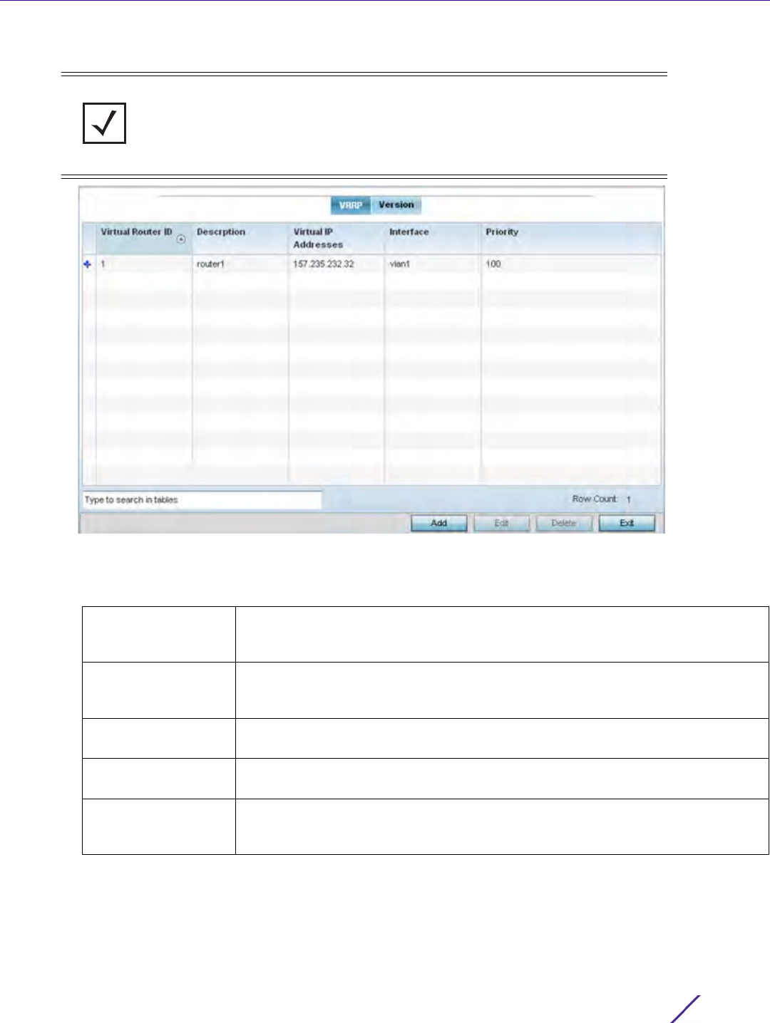
Device Configuration
Wireless Controller and Service Platform System Reference Guide 5 - 230
4Select
VRRP.
Figure 5-134 Profile Overrides - VRRP screen
5 Review the following VRRP configuration data to assess if a new VRRP configuration is required of is an existing
VRRP configuration requires modification or removal:
6 Select the Version tab to define the VRRP version scheme used with the configuration.
NOTE: A blue override icon (to the left of a parameter) defines the parameter as
having an override applied. To remove an override go to the Basic Configuration
section of the device and click the Clear Overrides button. This removes all
overrides from the device.
Virtual Router ID Lists a numerical index (1 - 255) used to differentiate VRRP configurations. The
index is assigned when a VRRP configuration is initially defined. This ID identifies
the virtual router a packet is reporting status for.
Description Displays a description assigned to the VRRP configuration when it was either
created or modified. The description is implemented to provide additional
differentiation beyond the numerical virtual router ID.
Virtual IP Addresses Lists the virtual interface IP address used as the redundant gateway address for
the virtual route.
Interface Displays the interfaces selected on the Access Point to supply VRRP redundancy
fail over support.
Priority Lists a numerical value (from 1 - 254) used for the virtual router master election
process. The higher the numerical value, the higher the priority in the election
process.
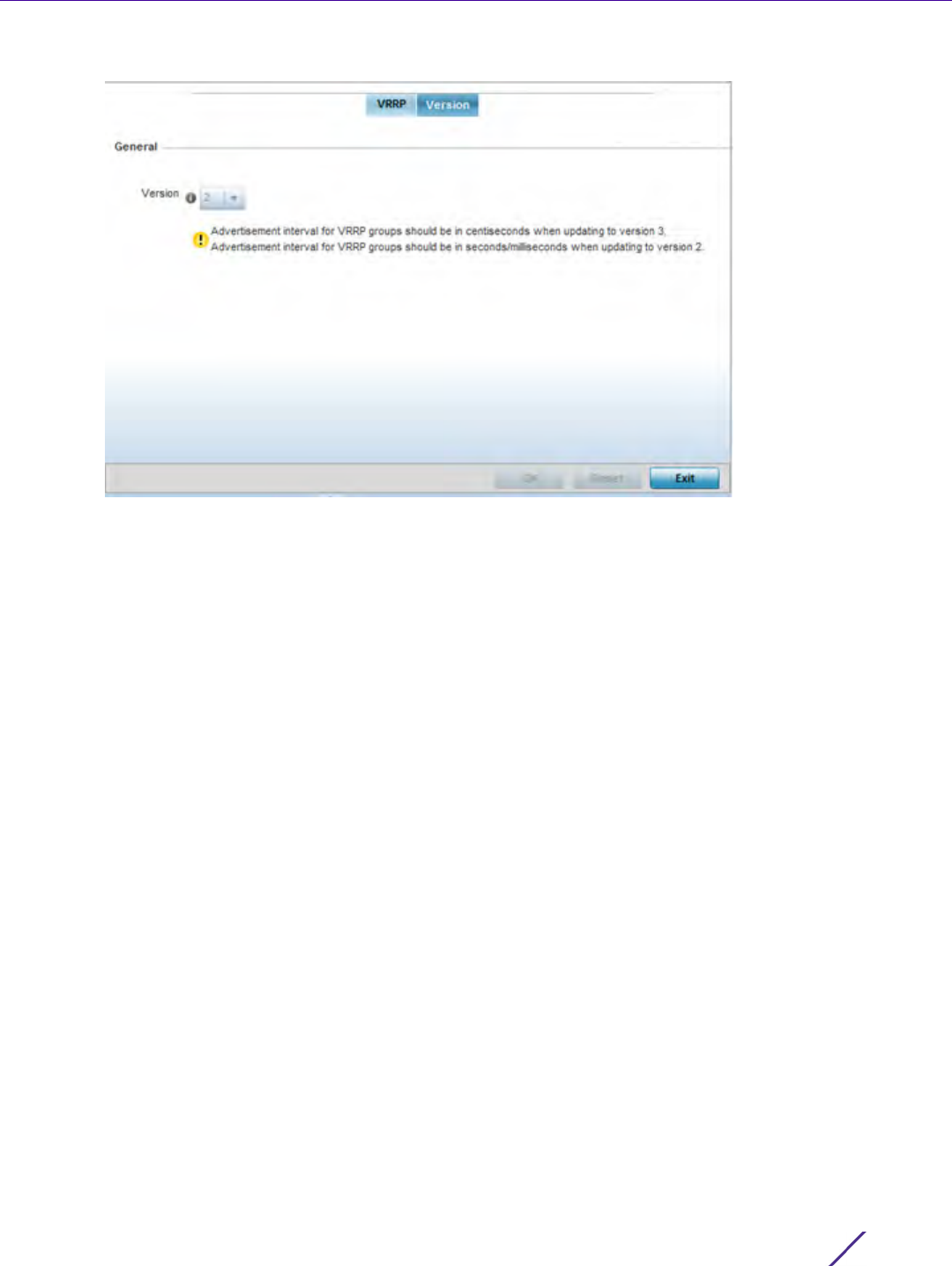
Device Configuration
Wireless Controller and Service Platform System Reference Guide 5 - 231
Figure 5-135 VRRP screen - Version tab
VRRP version 3 (RFC 5798) and 2 (RFC 3768) are selectable to set the router redundancy. Version 3 supports
sub-second (centisecond) VRRP failover and support services over virtual IP. For more information on the
VRRP protocol specifications (available publicly) refer to http://www.ietf.org/rfc/rfc3768.txt (version 2) and
http://www.ietf.org/rfc/rfc5798.txt (version 3).
7 From within VRRP tab, select Add to create a new VRRP configuration or Edit to modify the attributes of an
existing VRRP configuration. If necessary, existing VRRP configurations can be selected and permanently
removed by selecting Delete.
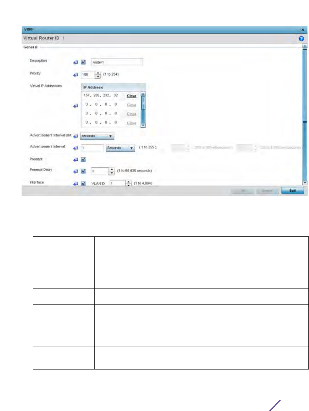
Device Configuration
Wireless Controller and Service Platform System Reference Guide 5 - 232
Figure 5-136 VRRP screen
8 If creating a new VRRP configuration, assign a Virtual Router ID from (1 - 255). In addition to functioning as
numerical identifier, the ID identifies the virtual router a packet is reporting status for.
9 Define the following VRRP General parameters:
Description In addition to an ID assignment, a virtual router configuration can be assigned a
textual description (up to 64 characters) to further distinguish it from others with
a similar configuration.
Priority Use the spinner control to set a VRRP priority setting from 1 - 254. The controller
or service platform uses the defined setting as criteria in selection of a virtual
router master. The higher the value, the greater the likelihood of this virtual router
ID being selected as the master.
Virtual IP Addresses Provide up to 8 IP addresses representing the Ethernet switches, routers or
security appliances defined as virtual router resources.
Advertisement
Interval Unit
Select either seconds, milliseconds or centiseconds as the unit used to define
VRRP advertisements. Once an option is selected, the spinner control becomes
enabled for that Advertisement Interval option. The default interval unit is
seconds. If changing the VRRP group version from 2 to 3, ensure the
advertisement interval is in centiseconds. Use VRRP group version 2 when the
advertisement interval is either in seconds or milliseconds.
Advertisement
Interval
Once an Advertisement Interval unit has been selected, use the spinner control to
set the interval the VRRP master sends out advertisements on each of its
configured VLANs. The default setting is 1 second.

Device Configuration
Wireless Controller and Service Platform System Reference Guide 5 - 233
10 Refer to the Protocol Extension field to define the following:
11 Select OK to save the changes made to the VRRP configuration. Select Reset to revert to the last saved
configuration.
5.2.9.10 Overriding a Profile’s Critical Resource Configuration
Profile Overrides
Critical resources are device IP addresses or destinations interopreted as critical to the health of the network. The
critical resource feature allows for the continuous monitoring of these defined addresses. A critical resource, if not
available, can result in the network suffering performance degradation. A critical resource can be a gateway, AAA
server, WAN interface or any hardware or service on which the stability of the network depends. Critical resources
are pinged regularly. If there’s a connectivity issue, an event is generated stating a critical resource is unavailable.
By default, there’s no enabled critical resource policy and one needs to be created and implemented.
Critical resources can be monitored directly through the interfaces on which they’re discovered. For example, a
critical resource on the same subnet as the access point can be monitored by its IP address. However, a critical
resource located on a VLAN must continue to monitored on that VLAN.
Preempt Select this option to ensure a high priority backup router is available to preempt a
lower priority backup router resource. The default setting is enabled. When
selected, the Preempt Delay option becomes enabled to set the actual delay
interval for pre-emption. This setting determines if a node with a higher priority
can take over all the Virtual IPs from the nodes with a lower priority.
Preempt Delay If the Preempt option is selected, use the spinner control to set the delay interval
(in seconds) for pre-emption.
Interface Select this value to enable/disable VRRP operation and define the VLAN (1 -
4,094) interface where VRRP will be running. These are the interfaces monitored
to detect a link failure.
Sync Group Select the option to assign a VRRP sync group to this VRRP ID’s group of virtual
IP addresses. This triggers VRRP fail over if an advertisement is not received from
the virtual masters that are part of this VRRP sync group. This setting is disabled
b y default.
Network Monitoring:
Local Interface
Select wwan1, pppoe1 and VLAN ID(s) as needed to extend VRRP monitoring to
these local Access Point interfaces. Once selected, these interfaces can be
assigned an increasing or decreasing level or priority for virtual routing within the
VRRP group.
Network Monitoring:
Critical Resource
Assign the priority level for the selected local interfaces. Backup virtual routers
can increase or decrease their priority in case the critical resources connected to
the master router fail, and then transition to the master state themselves.
Additionally, the master virtual router can lower its priority if the critical resources
connected to it fails, so the backup can transition to the master state. This value
can only be set on the backup or master router resource, not both. Options
include None, increment-priority, decrement priority.
Network Monitoring:
Critical Resource
Name
Select each critical resource needed for monitoring. The action specified in the
critical resource drop-down menu is applied to each selected critical resource.
Network Monitoring:
Delta Priority
Use this setting to decrement the configured priority (by the set value) when the
monitored interface is down. When critical resource monitoring, the value is
incremented by the setting defined.
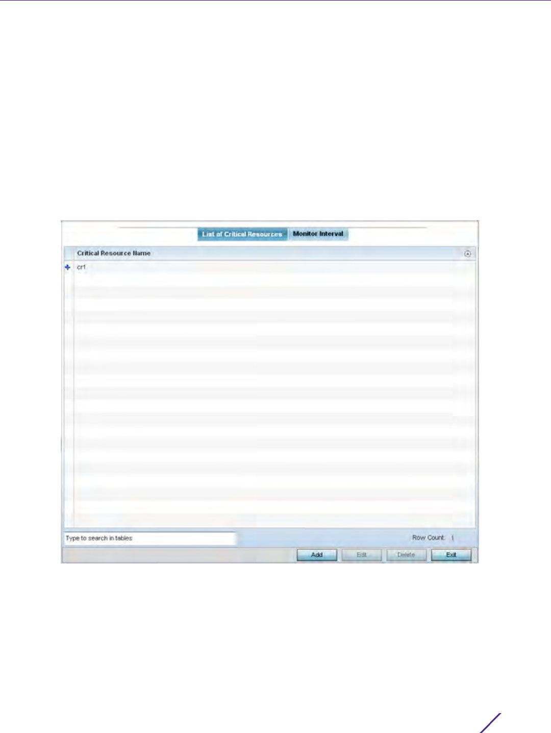
Device Configuration
Wireless Controller and Service Platform System Reference Guide 5 - 234
Critical resource can be configured for Access Points and wireless controllers using their respective profiles.
To define critical resources:
1Select
Devices from the Configuration tab.
The Device Configuration screen displays a list of devices or peer controllers, service platforms or Access
Points.
2 Select a target device (by double-clicking it) from amongst those displayed within the Device Configuration
screen.
Devices can also be selected directly from the Device Browser in the lower, left-hand, side of the UI.
3Select
Profile Overrides from the Device menu to expand it into sub menu options.
4Select
Critical Resources.
Figure 5-137 Critical Resources screen - List of Critical Resources tab
The screen lists the destination IP addresses or interfaces (VLAN, WWAN, or PPPoE) used for critical resource
connection. IP addresses can be monitored directly by the controller, service platform or Access Point whereas a
VLAN, WWAN or PPPoE must be monitored behind an interface.
5The
Critical Resource Name table displays the name of the resource(s) configured on this device.
6 Click the Add button at the bottom of the screen to add a new critical resource and connection method, or
select an existing resource and select Edit to update the resource’s configuration. If adding a new critical
resource, assign it a name up to 32 characters.
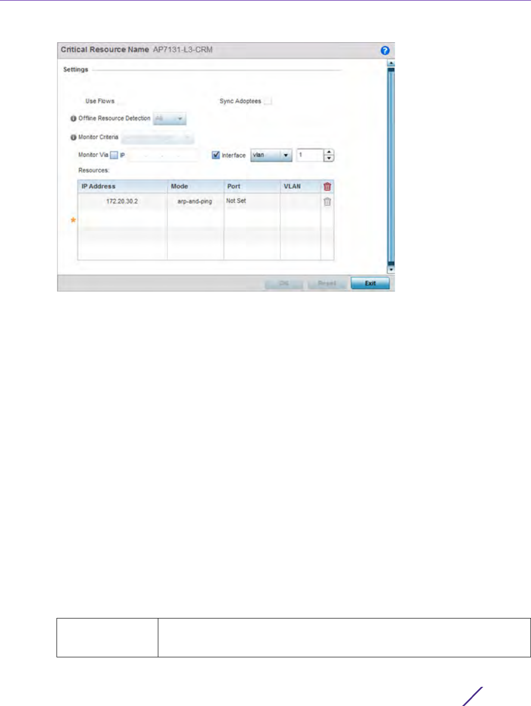
Device Configuration
Wireless Controller and Service Platform System Reference Guide 5 - 235
Figure 5-138 Critical Resources screen - Adding a Critical Resource
7Select Use Flows to configure the critical resource to monitor using firewall flows for DHCP or DNS instead of
ICMP or ARP packets to reduce the amount of traffic on the network. Select Sync Adoptees to sync adopted
devices to state changes with a resource-state change message. These settings are disabled by default.
8Use the Offline Resource Detection drop-down menu to define how critical resource event messages are
generated. Options include Any and All. If selecting Any, an event is generated when the state of any single
critical resource changes. If selecting All, an event is generated when the state of all monitored critical resources
change.
9Use the Monitor Criteria drop-down menu to select either rf-domain-manager, cluster-master or All as the
resource for monitoring critical resources by one device and updating the rest of the devices in a group.
If selecting rf-domain-manager, the current rf-domain manager performs resource monitoring, and the rest of
the devices do not. The RF-domain-manager updates any state changes to the rest of the devices in the RF
Domain. With the cluster-master option, the cluster master performs resource monitoring and updates the
cluster members with state changes. With a controller managed RF Domain, Monitoring Criteria should be set
tor All, since the controller might not know the VLAN bridged locally by the devices in the RF Domain
monitoring DHCP.
10 Select the IP option (within the Monitor Via field at the top of the screen) to monitor a critical resource directly
(within the same subnet) using the provided IP address as a network identifier.
11 Select the Interface check box (within the Monitor Via field at the top of the screen) to monitor a critical
resource using either the critical resource’s VLAN, WWAN1 or PPPoE1 interface. If VLAN is selected, a spinner
control is enabled to define the destination VLAN ID used as the interface for the critical resource.
12 Select + Add Row to define the following for critical resource configurations:
IP Address Provide the IP address of the critical resource. This is the address used by the
Access Point to ensure the critical resource is available. Up to four addresses can
be defined.
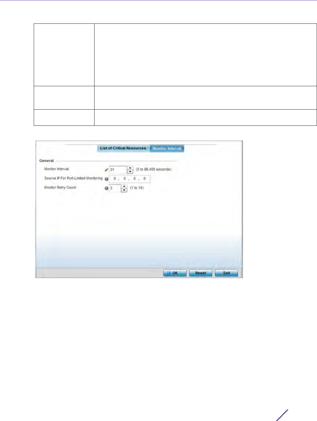
Device Configuration
Wireless Controller and Service Platform System Reference Guide 5 - 236
13 Select the Monitor Interval tab.
Figure 5-139 Critical Resources screen - Monitor Interval tab
Set Monitor Interval as the duration between two successive pings to the critical resource. Define this value in
seconds from 5 - 86,400. The default setting is 30 seconds.
14 Set the Source IP for Port-Limited Monitoring to define the IP address used as the source address in ARP
packets used to detect a critical resource on a layer 2 interface. Generally, the source address 0.0.0.0 is used in
the APR packets used to detect critical resources. However, some devices do not support the above IP address
and drop the ARP packets. Use this field to provide an IP address specifically used for this purpose. The IP
address used for Port-Limited Monitoring must be different from the IP address configured on the device.
15 Set the Monitoring Retries before Marking Resource as DOWN for the number of retry connection attempts (1 -
10) permitted before this device connection is defined as down (offline). The default setting is three connection
attempts.
16 Select OK to save the changes to the critical resource configuration and monitor interval. Select Reset to revert
to the last saved configuration.
Mode Set the ping mode used when the availability of a critical resource is validated.
Select from:
arp-only – Use the Address Resolution Protocol (ARP) for only pinging the critical
resource. ARP is used to resolve hardware addresses when only the network layer
address is known.
arp-and-ping – Use both ARP and Internet Control Message Protocol (ICMP) for
pining the critical resource and sending control messages (device not reachable,
requested service not available, etc.).
Port Define the interface on which to monitor critical resource. This field lists the
available hardware interfaces. This option is only available if the selected mode is
ARP Only.
VLAN Define the VLAN on which the critical resource is available using the spinner
control.
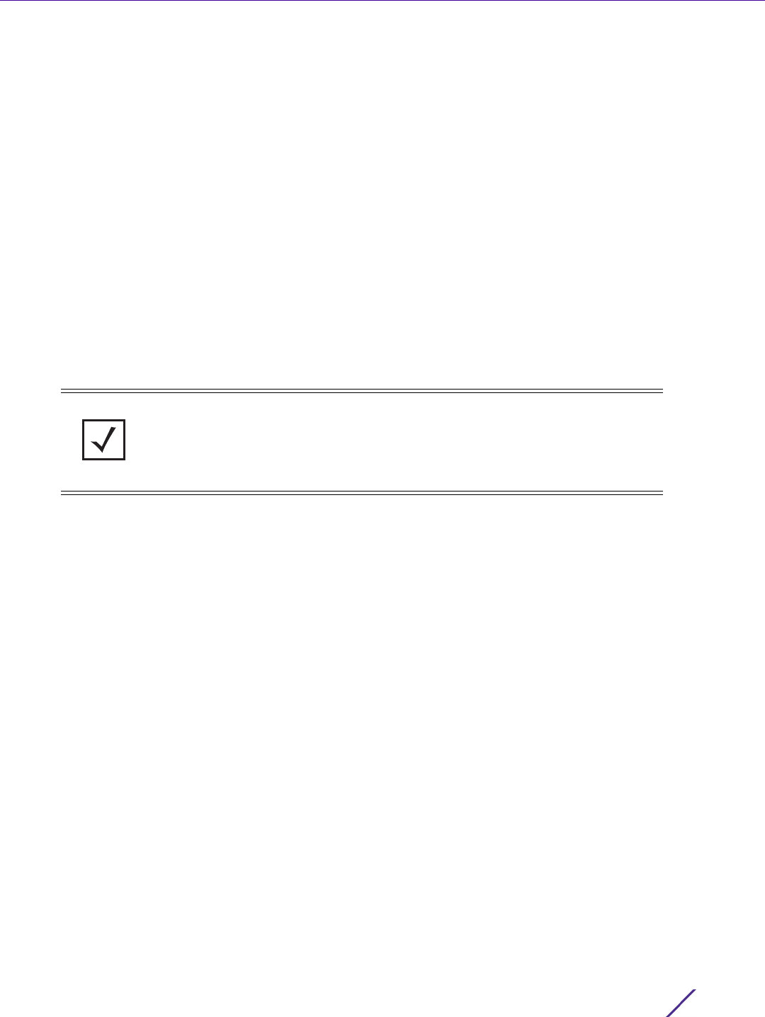
Device Configuration
Wireless Controller and Service Platform System Reference Guide 5 - 237
5.2.9.11 Overriding a Profile’s Services Configuration
Profile Overrides
A profile can contain specific guest access (captive portal), DHCP server and RADIUS server configurations
supported by the controller, service platform or Access Point’s own internal resources. These access, IP assignment
and user authorization resources can be defined uniquely as profile requirements dictate.
To define or override a profile’s services configuration:
1Select
Devices from the Configuration tab.
The Device Configuration screen displays a list of devices or peer controllers, service platforms or Access
Points.
2 Select a target device (by double-clicking it) from amongst those displayed within the Device Configuration
screen.
Devices can also be selected directly from the Device Browser in the lower, left-hand, side of the UI.
3Select
Profile Overrides from the Device menu to expand it into sub menu options.
4Select
Services.
NOTE: A blue override icon (to the left of a parameter) defines the parameter as
having an override applied. To remove an override go to the Basic Configuration
section of the device and click the Clear Overrides button. This removes all
overrides from the device.
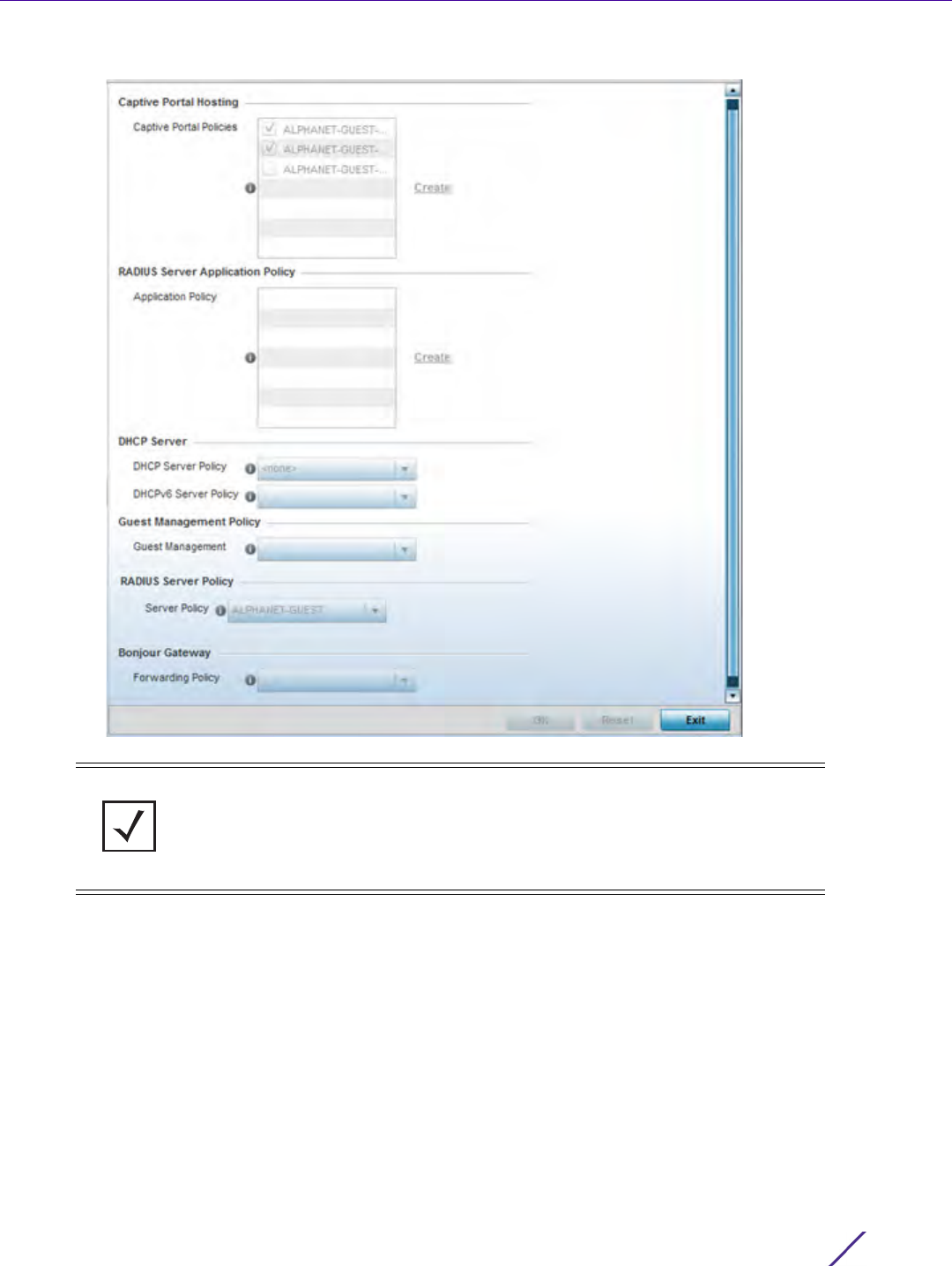
Device Configuration
Wireless Controller and Service Platform System Reference Guide 5 - 238
Figure 5-140 Profile Overrides - Services screen
5 Refer to the Captive Portal Hosting field to set or override the guest access configuration (captive portal) for
this profile.
A captive portal is an access policy for providing guests temporary and restrictive access to the wireless
network.
A captive portal configuration provides secure authenticated controller or service platform access using a
standard Web browser. Hotspots provides authenticated access by capturing and re-directing a wireless user's
Web browser session to a captive portal login page where the user must enter valid credentials to access to
the wireless network. Once logged into the captive portal additional Agreement, Welcome and Fail pages
provide the administrator with a number of options on the hotspot’s screen flow and user appearance.
Either select an existing captive portal policy, use the default captive portal policy or select the Create link to
create a new configuration that can be applied to this profile. For more information, see Configuring Captive
Portal Policies on page 11-1.
NOTE: A blue override icon (to the left of a parameter) defines the parameter as
having an override applied. To remove an override go to the Basic Configuration
section of the device and click the Clear Overrides button. This removes all
overrides from the device.

Device Configuration
Wireless Controller and Service Platform System Reference Guide 5 - 239
6Use the RADIUS Server Application Policy drop-down menu to select an application policy to authenticate users
and authorize access to the network. A RADIUS policy provides the centralized management of authentication
data (usernames and passwords). When an client attempts to associate, the controller or service platform sends
the authentication request to the RADIUS server.
If an existing RADIUS server policy does not meet your requirements, select the Create link to create a new
policy.
7Use the DHCP Server Policy drop-down menu assign this profile a DHCP server policy. If an existing DHCP
policy does not meet the profile’s requirements, select the Create icon to create a new policy configuration that
can be applied to this profile or the Edit icon to modify the parameters of an existing DHCP Server policy.
Dynamic Host Configuration Protocol (DHCP) allows hosts on an IP network to request and be assigned IP
addresses as well as discover information about the network where they reside. Each subnet can be configured
with its own address pool. Whenever a DHCP client requests an IP address, the DHCP server assigns an IP
address from that subnet’s address pool. When the onboard DHCP server allocates an address for a DHCP
client, the client is assigned a lease, which expires after an pre-determined interval. Before a lease expires,
wireless clients (to which leases are assigned) are expected to renew them to continue to use the addresses.
Once the lease expires, the client is no longer permitted to use the leased IP address. The profile’s DHCP server
policy ensures all IP addresses are unique, and no IP address is assigned to a second client while the first
client's assignment is valid (its lease has not expired).
8Use the DHCPv6 Server Policy drop-down menu assign this profile a DHCPv6 server policy. If an existing DHCP
policy for IPv6 does not meet the profile’s requirements, select the Create icon to create a new policy
configuration that can be applied to this profile or the Edit icon to modify the parameters of an existing DHCP
Server policy.
DHCPv6 is a networking protocol for configuring IPv6 hosts with IP addresses, IP prefixes or other
configuration attributes required on an IPv6 network. DHCP in IPv6 works in with IPv6 router discovery. With
the proper RA flags, DHCPv6 works like DHCP for IPv4. The central difference is the way a device identifies
itself if assigning addresses manually instead of selecting addresses dynamically from a pool.
For more information, see Configuring a Captive Portal Policy on page 11-2.
9Use the Guest Management Policy drop-down menu to select an existing Guest Management policy to use as a
mechanism to manage guest users with this profile.
10 Use the RADIUS Server Policy drop-down menu to select an existing RADIUS server policy to use as a user
validation security mechanism with this profile.
A profile can have its own unique RADIUS server policy to authenticate users and authorize access to the
network. A profile’s RADIUS policy provides the centralized management of controller or service platform
authentication data (usernames and passwords). When an client attempts to associate, an authentication
request is sent to the RADIUS server.For more information, see Configuring RADIUS Server Policies on page 11-
57.
11 Set Bonjour Gateway settings. Bonjour is Apple’s implementation of zero-configuration networking (Zeroconf).
Zeroconf is a group of technologies that include service discovery, address assignment and hostname
resolution. Bonjour locates devices such as printers, other computers and services that these computers offer
over a local network.
Bonjour provides a general method to discover services on a local area network (LAN). It allows users to set up
a network without any configuration. Services such as printers, scanners and file-sharing servers can be found
using Bonjour. Bonjour only works within a single broadcast domain. However, with special DNS configuration,
it can be extended to find services across broadcast domains.
12 From the Forwarding Policy drop-down, select the Bonjour Gateway forwarding policy. n.

Device Configuration
Wireless Controller and Service Platform System Reference Guide 5 - 240
13 Select OK to save the changes or overrides made to the profile’s services configuration. Select Reset to revert
to the last saved configuration.
5.2.9.12 Overriding a Profile’s Management Configuration
Profile Overrides
Controllers and service platforms have mechanisms to allow/deny management access to the network for separate
interfaces and protocols (HTTP, HTTPS, Telnet, SSH or SNMP). These management access configurations can be
applied strategically to profiles as resource permissions dictate. Additionally, overrides can be applied to customize
a device’s management configuration, if deployment requirements change an a devices configuration must be
modified from its original device profile configuration.
Additionally, an administrator can define a profile with unique configuration file and device firmware upgrade
support. In a clustered environment, these operations can be performed on one controller or service platform, then
propagated to each member of the cluster and onwards to devices managed by each cluster member.
To define or override a profile’s management configuration:
1Select
Devices from the Configuration tab.
The Device Configuration screen displays a list of devices or peer controllers, service platforms or Access
Points.
2 Select a target device (by double-clicking it) from amongst those displayed within the Device Configuration
screen.
Devices can also be selected directly from the Device Browser in the lower, left-hand, side of the UI.
3Select
Profile Overrides from the Device menu to expand it into sub menu options.
4Expand the
Management menu item and select Settings.
NOTE: A blue override icon (to the left of a parameter) defines the parameter as
having an override applied. To remove an override go to the Basic Configuration
section of the device and click the Clear Overrides button. This removes all
overrides from the device.
Device Configuration
Wireless Controller and Service Platform System Reference Guide 5 - 241
Figure 5-141 Profile Overrides - Management Settings screen
5 Refer to the Management Policy field to set or override a management configuration for this profile. A default
management policy is also available if no existing policies are usable.
Use the drop-down menu to select an existing management policy to apply to this profile. If no management
policies exist meeting the data access requirements of this profile, select the Create icon to access screens
used to define administration, access control and SNMP configurations. Select an existing policy and select the
NOTE: A blue override icon (to the left of a parameter) defines the parameter as
having an override applied. To remove an override go to the Basic Configuration
section of the device and click the Clear Overrides button. This removes all
overrides from the device.

Device Configuration
Wireless Controller and Service Platform System Reference Guide 5 - 242
Edit icon to modify the configuration of an existing management policy. For more information, see Viewing
Management Access Policies on page 12-1.
6 Refer to the Message Logging field to define how the profile logs system events. It’s important to log individual
events to discern an overall pattern potentially impacting performance.
7 Refer to the System Event Messages section to define or override how controller or service platform system
messages are logged and forwarded on behalf of the profile.
Enable Message
Logging
Select this option to enable the profile to log system events to a log file or a
syslog server. Selecting this check box enables the rest of the parameters
required to define the profile’s logging configuration. This option is disabled by
default.
Remote Logging Host Use this table to define numerical (non DNS) IP addresses for up to three
external resources where logged system events can be sent on behalf of the
profile. Select the Delete icon as needed to remove an IP address.
Facility to Send Log
Messages
Use the drop-down menu to specify the local server (if used) for profile event
log transfers.
Syslog Logging Level Event severity coincides with the syslog logging level defined for the profile.
Assign a numeric identifier to log events based on criticality. Severity levels
include 0 - Emergency, 1 - Alert, 2 - Critical, 3 - Errors, 4 - Warning, 5 - Notice,
6 - Info and 7 - Debug. The default logging level is 4.
Console Logging Level Event severity coincides with the syslog logging level defined for the profile.
Assign a numeric identifier to log events based on criticality. Severity levels
include 0 - Emergency, 1 - Alert, 2 - Critical, 3 - Errors, 4 - Warning, 5 - Notice,
6 - Info and 7 - Debug. The default logging level is 4.
Buffered Logging Level Event severity coincides with the syslog logging level defined for the profile.
Assign a numeric identifier to log events based on criticality. Severity levels
include 0 - Emergency, 1 - Alert, 2 - Critical, 3 - Errors, 4 - Warning, 5 - Notice,
6 - Info and 7 - Debug. The default logging level is 4.
Time to Aggregate
Repeated Messages
Define the increment (or interval) system events are logged on behalf of the
profile. The shorter the interval, the sooner the event is logged. Either define
an interval in Seconds
(0 - 60) or Minutes (0 -1). The default value is 0 seconds.
Forward Logs to
Controller
Select the check box to define a log level for forwarding event logs. Log levels
include Emergency, Alert, Critical, Error, Warning, Notice, Info and Debug. The
default logging level is Error.
Event System Policy Select an Event System Policy from the drop-down menu. If an appropriate
policy does not exist, select the Create button to make a new policy.
Enable System Events Select the Enable System Events check box to allow the profile to capture
system events and append them to a log file. It’s important to log individual
events to discern an overall pattern that may be negatively impacting
controller or service platform performance. This setting is enabled by default.
Enable System Event
Forwarding
Select the Enable System Event Forwarding radio button to forward system
events to another controller, service platform or cluster member. This setting is
enabled by default.

Device Configuration
Wireless Controller and Service Platform System Reference Guide 5 - 243
8 Refer to the Events E-mail Notification section to define or override how system event notification Emails are
sent.
9 Refer to the Persist Configurations Across Reloads section to define or override how configuration settings are
handled after reloads.
10 Refer to the HTTP Analytics field to define analytic compression settings and update intervals.
11 Refer to the External Analytics Engine section to define or override analytics engine login information for an
external host.
The Guest Access & Analytics software module is a site-wide Enterprise License available only on service
platforms. When a customer visits a store, they connect to the Wireless LAN via guest access using a mobile
device. The user needs to authenticate only on their first visit, and will automatically connect to the network for
subsequent visits. The Analytics module helps gather data about customer behavior such as web sites visited,
search terms used, mobile device types, number of new users vs. repeat users. This data provides a better
understanding of pricing strategies and promotions being run by competitors. The data can be exported for
additional in-depth analysis.
SMTP Server Specify either the Hostname or IP Address of the outgoing SMTP server where
notification Emails are originated. Hostnames cannot include an underscore
character.
Port of SMTP If a non-standard SMTP port is used on the outgoing SMTP server, select this
option and specify a port from 1 - 65,535 for the outgoing SMTP server to use.
Sender E-mail Address Specify the Email address from which notification Email is originated. This is
the from address on notification Email.
Recipient’s E-mail
Address
Specify up to 6 Email addresses to be the recipient’s of event Email
notifications.
Username for SMTP
Server
Specify the sender username on the outgoing SMTP server. Many SMTP
servers require users to authenticate with a username and password before
sending Email through the server.
Password for SMTP
Server
Specify the password associated with the username of the sender on the
outgoing SMTP server. Many SMTP servers require users to authenticate with a
username and password before sending Email through the server.
Configure Use the drop-down menu to configure whether configuration overrides should
persist when the device configuration is reloaded. Available options are
Enabled, Disabled and Secure.
Compress Select this option to use compression to when sending updates to the
controller. This option is disabled by default.
Update Interval Define an interval in either Seconds (1 - 3,600), Minutes (1 - 60) or Hours (1) for
interval to push buffered packets. The default setting in 1 minute.
Controller Select this option to provide service platform analytics to a local device. This
setting is enabled by default.
URL When using an external analytics engine with a NX9000 series service
platform, enter the IP address or uniform resource locator (URL) for the
system providing external analytics functions.
User Name Enter the user name needed to access the external analytics engine.
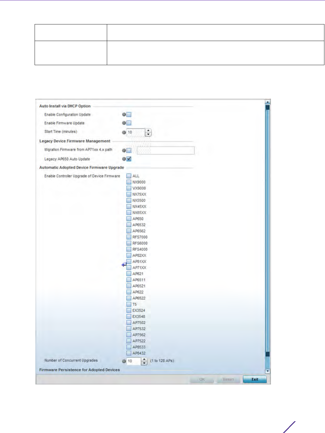
Device Configuration
Wireless Controller and Service Platform System Reference Guide 5 - 244
12 Select OK to save the changes and overrides made to the profile’s Management Settings. Select Reset to revert
to the last saved configuration.
13 Select Firmware from the Management menu.
Figure 5-142 Profile Overrides - Management Firmware screen
Password Enter the password associated with the username on the external analytics
engine.
Update Interval Set the interval in either Seconds (1 - 3,600), Minutes (1 - 60) or Hours (1) to
forward buffered information to an external server resource, even when the
buffers are not full. The default setting in 1 minute.

Device Configuration
Wireless Controller and Service Platform System Reference Guide 5 - 245
14 Refer to the Auto Install via DHCP Option field to configure automatic configuration file and firmware updates.
15 Refer to the parameters within the Legacy Device Firmware Management field to set legacy Access Point
firmware provisions:
16 Use the parameters within the Automatic Adopted AP Firmware Upgrade section to define an automatic
firmware upgrade from a local file.
17 Select the Persist AP Images on Controller button (from within the Firmware Persistence for Adopted Devices
field) to enable the RF domain manager to retain and store the new image of an Access Point selected for a
firmware update. The image is only stored on the RF domain manager when there’s space to accommodate it.
The upgrade sequence is different depending on whether the designated RF domain manager is a controller/
service platform or Access Point.
•When the RF domain manager is an Access Point - The NOC uploads a provisions an Access Point model’s
firmware on to the Access Point RF domain manager. The NOC initiates an auto-update for Access Points
using that model’s firmware. If the Persist Image on Controller option is selected, the RF domain manager
retains the image for that model. The NOC then provisions the firmware of the next Access Point type to the
RF domain manager. The auto-update process is then repeated for that model. Once all the selected models
have been updated, the RF domain manager’s model is updated last.
•When the RF domain manager is a controller or service platform - The NOC adopts controllers to the NOC’s
cluster within its RF domain. The NOC triggers an update on active controllers or service platforms and
reboots them as soon as the update is complete. As soon as the active nodes come back up, the NOC
Enable Configuration
Update
Select Enable Configuration Update (from within the Automatic Configuration
Update field) to enable automatic profile configuration file updates from an
external location.
If enabled (the setting is disabled by default), provide a complete path to the
target configuration file used in the update.
Enable Firmware
Update
Select this option to enable automatic firmware upgrades (for this profile)
from a user defined remote location. This value is disabled by default.
Start Time (minutes) Use the spinner control to set the number of minutes to delay the start of an
auto upgrade operation. Stagger the start of an upgrade operation as needed
in respect to allowing an Access Point to complete its current client support
activity before being rendered offline during the update operation. The default
setting is 10 minutes.
Migration Firmware
from AP71xx 4.x path
Provide a path to a firmware image used to provision AP71xx model Access
Points currently utilizing a 4.x version legacy firmware file. Once a valid path is
provided, the update is enabled to the version maintained locally for AP71xx
models.
Legacy AP650 Auto
Update
Select this option to provision AP650 model Access Points from their legacy
firmware versions to the version maintained locally for that model. This setting
is enabled by default, making updates to AP650 models automatic if a newer
AP650 image is maintained locally.
Enable Controller
Upgrade of Device
Firmware
Select the device model to upgrade using the most recent firmware file on the
controller, service platform or Virtual Controller AP. This parameter is enabled
by default. Select All to update all the listed device types
Number of Concurrent
Upgrades
Use the spinner control to define the maximum number (1 - 128) of adopted
APs that can receive a firmware upgrade at the same time. The default value is
10. Keep in mind that during a firmware upgrade, the Access Point is offline
and unable to perform its normal client support role until the upgrade process
is complete.

Device Configuration
Wireless Controller and Service Platform System Reference Guide 5 - 246
triggers an update on standby controllers or service platforms and reboots them as soon as the update is
complete. When the standby controllers or service platforms come back up the following conditions apply:
-If the reboot is not scheduled - The Access Points adopted to RF domain members are not updated. It’s
expected the controllers and service platforms have auto-upgrade enabled which will update the Access
Points when re-adopted.
-If the reboot is scheduled - The NOC pushes the first Access Point model’s firmware to the RF domain
manager. The NOC initiates an Access Point upgrade on all Access Points on the RF domain manager for that
model. If the Persist Image on Controller option is selected, the RF domain manager retains the image for
that model. The NOC then provisions the firmware of the next Access Point type to the RF domain manager.
This process is repeated until each selected Access Point model is updated.
The Firmware Persistence feature is enabled for all controller and service platform RF domain managers with
the flash memory capacity to store firmware images for the selected Access Point models they provision. This
feature is disabled for Access Point RF Domain managers that do not typically have the flash memory capacity
needed.
18 Select Heartbeat from the Management menu. Select the Service Watchdog option to implement heartbeat
messages to ensure associated devices are up and running and capable of effectively interoperating. The
Service Watchdog is enabled by default.
19 Select OK to save the changes and overrides made to the profile’s configuration. Select Reset to revert to the
last saved configuration.
5.2.9.13 Overriding a Profile’s Mesh Point Configuration
Profile Overrides
Mesh points are Access Points dedicated to mesh network support. Mesh networking enables users to access
broadband applications anywhere (including moving vehicles).
To set or override an Access Point profile’s Mesh Point configuration:
1Select
Devices from the Web UI.
2Select
Device Configuration to expand its menu items.
3Select
Mesh Point.
NOTE: A blue override icon (to the left of a parameter) defines the parameter as
having an override applied. To remove an override go to the Basic Configuration
section of the device and click the Clear Overrides button. This removes all
overrides from the device.
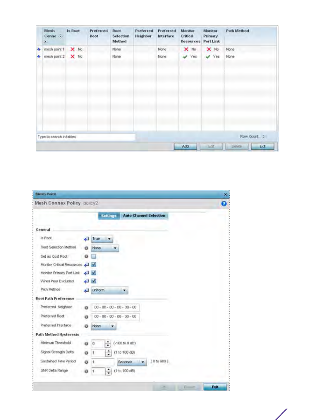
Device Configuration
Wireless Controller and Service Platform System Reference Guide 5 - 247
Figure 5-143 Profile Overrides - Mesh Point screen
4 Refer to the Mesh Point screen to view existing Mesh Point overrides. If an existing Mesh Point override does
not meet your requirements, select the Add button to create a new override or the Edit button to modify the
parameters of an existing override. The Mesh Point screen displays the Settings tab by default.
Figure 5-144 Mesh Point - Settings Screen

Device Configuration
Wireless Controller and Service Platform System Reference Guide 5 - 248
5 Define the following settings from within the General field:
MeshConnex Policy If adding a new policy, specify a name for the MeshConnex Policy. The name
cannot be edited later with other configuration parameters. Until a viable
name is provided, the Settings tab cannot be enabled for configuration.
Is Root Select the root behavior of this mesh point. Select True to indicate this mesh
point is a root node for this mesh network. Select False to indicate this mesh
point is not a root node for this mesh network.
Root Selection Method Use the drop-down menu to determine whether this meshpoint is the root or
non-root meshpoint. Select either None, auto-mint or auto-proximity. The
default setting is None. When auto-mint is selected, root selection is based on
the total cost to the root. Cost to the root is measured as total cost through
hops to the root node. Root selection occurs for the root with the least path
cost. When auto-proximity is selected, root selection is based on signal
strength of candidate roots. None indicates no preference in root selection.
Set as Cost Root Select this option to set the mesh point as the cost root for meshpoint root
selection. This setting is disabled by default.
Monitor Critical
Resources
Enable this feature to allow dynamic conversion of a mesh point from root to
non-root when there is a critical resource failure. This option is disabled by
default.
Monitor Primary Port
Link
Enable this feature to allow dynamic conversion of a mesh point from root to
non-root during a link down event. This option is disabled by default.
Wired Peer Excluded Select this option to exclude a mesh from forming a link with another mesh
device that's a wired peer. This option is disabled by default.
Path Method From the drop-down menu, select the method to use for path selection in a
mesh network. The available options are:
None – Select this to indicate no criteria used in root path selection.
uniform – Select this to indicate that the path selection method is uniform.
When selected, two paths will be considered equivalent if the average value is
the same for these paths.
mobile-snr-leaf – Select this if this Access Point is mounted on a vehicle or a
mobile platform (AP7161 models only). When selected, the path to the route
will be selected based on the Signal To Noise Ratio (SNR) to the neighbor
device.
snr-leaf – Select this to indicate the path with the best signal to noise ratio is
always selected.
bound-pair – Select this option to bind one mesh point connection at a time.
Once established, other mesh point connection requests are denied.
NOTE: An AP7161 model Access Point can be deployed as a vehicular mounted
modem (VMM) to provide wireless network access to a mobile vehicle (car, train
etc.). A VMM provides layer 2 mobility for connected devices. VMM does not
provide layer 3 services, such as IP mobility. For VMM deployment considerations,
see Vehicle Mounted Modem (VMM) Deployment Considerations on page 5-
253.
NOTE: When using 4.9GHz, the root preferences selection for the radio’s preferred
interface still displays as 5GHz.

Device Configuration
Wireless Controller and Service Platform System Reference Guide 5 - 249
6 Set the following Root Path Preference values:
7 Set the following Path Method Hysteresis:
8 Select the Auto Channel Selection tab.
Preferred Neighbor Specify the MAC address of a preferred neighbor to override mesh point
settings.
Preferred Root Specify the MAC address of a a preferred root device to override mesh point
settings.
Preferred Interface Use the drop-down menu to override the preferred mesh point interface to
2.4GHz, 4.9 GHz or 5.0GHz. None defines the interface as open to any radio
band.
Minimum Threshold Enter the minimum value for SNR above which a candidate for the next hop in
a dynamic mesh network is considered for selection. This field along with
Signal Strength Delta and Sustained Time Period are used to dynamically
select the next hop in a dynamic mesh network. The default setting is 0 dB.
Signal Strength Delta Enter a delta value in dB. A candidate for selection as a next hop in a dynamic
mesh network must have a SNR value that is higher than the value configured
here. This field along with the Minimum Threshold and Sustained Time Period
are used to dynamically select the next hop in a dynamic mesh network. The
default setting is 1 dB.
Sustained Time Period Enter the duration (in seconds or minutes) for the duration a signal must
sustain the constraints specified in the Minimum Threshold and Signal Strength
Delta path hysteresis values. These values are used to dynamically select the
next hop in a dynamic mesh network. The default setting is 1 second.
SNR Delta Range Select the root selection method hysteresis (from 1 - 100dB) SNR delta range a
candidate must sustain. The default setting is 1 dB.
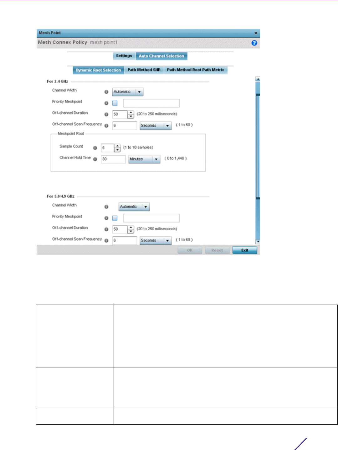
Device Configuration
Wireless Controller and Service Platform System Reference Guide 5 - 250
Figure 5-145 Mesh Point Auto Channel Selection - Dynamic Root Selection screen
The Dynamic Root Selection screen displays by default. The Dynamic Root Selection screen provides
configuration for the 2.4 GHz and 5.0/4.9 GHz frequencies.
9 Refer to the following. These descriptions are common for configuring either the 2.4 GHZ and 5.0/4.9 GHz
frequencies
Channel Width Set the channel width the meshpoint’s automatic channel scan assigns to the
selected radio. Available options include:
•Automatic – Defines the channel width is calculated automatically. This is the
default value.
•20 MHz – Sets the width between two adjacent channels as 20 MHz.
•40 MHz – Sets the width between two adjacent channels as 40 MHz.
•80 MHz – Utilized for 802.11ac Access Points in the 5 GHz frequency.
Priority Meshpoint Configure the meshpoint monitored for automatic channel scans. This is the
meshpoint assigned priority over other available mesh points. When
configured, a mesh connection is established with this mesh point. If not
configured, a meshpoint is automatically selected. This setting is disabled by
default.
Off-channel Duration Set the duration (from 20 - 250 milliseconds) the scan dwells on each channel
when performing an off channel scan. The default is 50 milliseconds.
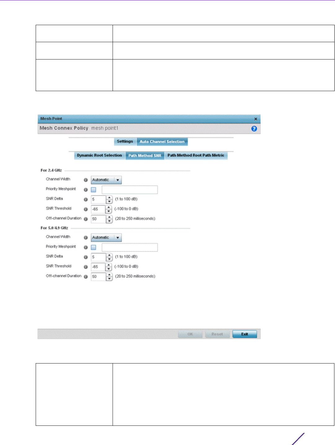
Device Configuration
Wireless Controller and Service Platform System Reference Guide 5 - 251
10 Select the Path Method SNR tab to configure signal to noise (SNR) ratio values when selecting the path to the
meshpoint root.
Figure 5-146 Mesh Point Auto Channel Selection - Path Method SNR screen
11 Set the following 2.4 GHz and 5.0/4.9 GHz path method SNR data:
Off-channel Scan
Frequency
Set the duration (from 1- 60 seconds) between two consecutive off channel
scans. The default is 6 seconds.
Meshpoint Root: Sample
Count
Configure the number of scan samples (from 1- 10) for data collection before a
mesh channel is selected. The default is 5.
Meshpoint Root: Channel
Hold Time
Configure the duration (from 0 - 1440 minutes) to remain on a channel before
channel conditions are reassessed for a possible channel change. Set this
value to zero (0) to prevent an automatic channel selection from occurring.
The default setting is 30 minutes.
Channel Width Set the channel width the meshpoint automatic channel scan assigns to the
selected radio. Available options include:
•Automatic – Defines the channel width calculation automatically. This is the
default value.
•20 MHz – Sets the width between two adjacent channels as 20 MHz.
•40 MHz – Sets the width between two adjacent channels as 40 MHz.
•80 MHz – Utilized for 802.11ac Access Points in the 5 GHz frequency.
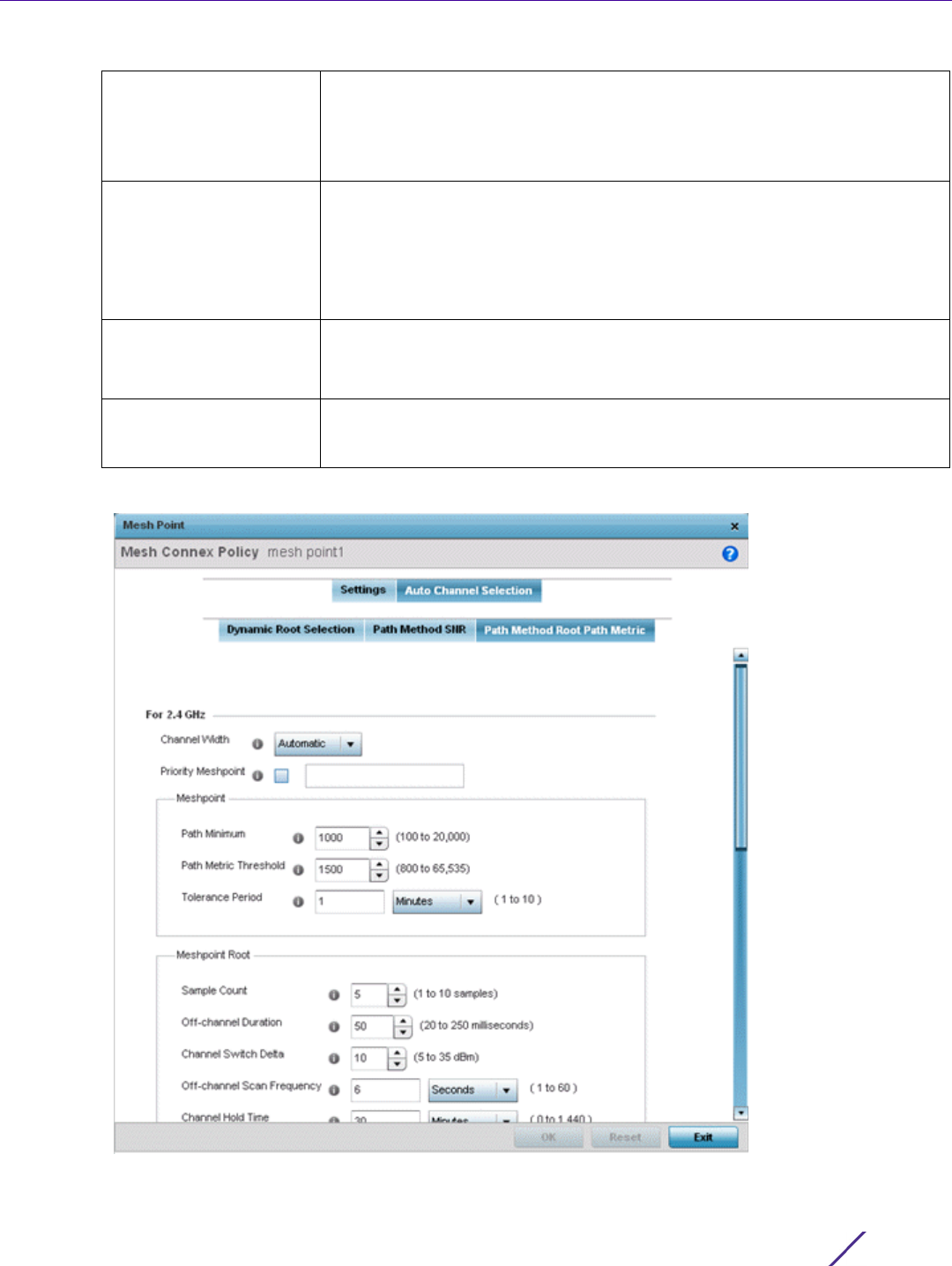
Device Configuration
Wireless Controller and Service Platform System Reference Guide 5 - 252
12 Select the Path Method Root Path Metric tab to calculate root path metrics.
Figure 5-147 Mesh Point Auto Channel Selection - Root Path Metric screen
Priority Meshpoint Set the meshpoint monitored for automatic channel scans. This is the
meshpoint assigned priority over other available mesh points. When
configured, a mesh connection is established with this mesh point. If not
configured, a meshpoint is automatically selected. This setting is disabled by
default.
SNR Delta Set the signal to noise (SNR) ratio delta (from 1 - 100 dB) for mesh path
selections.
When path selection occurs, the defined value is utilized for selecting the
optimal path. A better candidate, on a different channel, must have a signal
strength that exceeds this delta value when compared to the signal strength
of the next hop in the mesh network. The default setting is 5 dB.
SNR Threshold Set the SNR threshold for mesh path selections (from -100 to 0 dB).
If the signal strength of the next mesh hop falls below this set value, a scan is
triggered to select a better next hop. the default setting is -65 dB.
Off-channel Duration Configure the duration (from 20 - 250 milliseconds) for scan dwells on each
channel, when performing an off channel scan. The default setting is 50
milliseconds.

Device Configuration
Wireless Controller and Service Platform System Reference Guide 5 - 253
13 Set the following Path Method Root Path Metrics (applying to both the 2.4 GHz and 5.0/4.9 GHz frequencies):
14 Select OK to save the updates or overrides to the Mesh Point configuration. Select Reset to revert to the last
saved configuration.
5.2.9.13.7 Vehicle Mounted Modem (VMM) Deployment Considerations
Before defining a VMM configuration (mounting an AP7161 mesh point on a moving vehicle), refer to the following
deployment guidelines to ensure the configuration is optimally effective:
• Disable layer 2 stateful packet inspection from the firewall policy. For more information, see Firewall Policy
Advanced Settings on page 10-10.
• Set the RTS threshold value to 1 on all mesh devices. The default is 2347. For more information on defining radio
settings, refer to Access Point Radio Configuration on page 8-55.
•Use Opportunistic as the rate selection setting for the AP7161 radio. The default is Standard. For more
information on defining this setting, see Radio Override Configuration.
• Disable Dynamic Chain Selection (radio setting). The default is enabled. This setting can be disabled in the CLI
using the dynamic-chain-selection command, or in the UI (refer to Radio Override Configuration).
Channel Width Set the channel width meshpoint automatic channel scan should assign to the
selected radio. The available options are:
•Automatic – Defines the channel width as calculated automatically. This is the
default value.
•20 MHz – Set the width between two adjacent channels as 20 MHz.
•40 MHz – Set the width between two adjacent channels as 40 MHz
•80 MHz – Utilized for 802.11ac Access Points in the 5 GHz frequency.
Priority Meshpoint Define the meshpoint assigned priority over other available mesh points.
When configured, a mesh connection is established with this mesh point. If
not configured, a meshpoint is automatically selected.
Meshpoint: Path
Minimum
Set the minimum path metric (from 100 - 20,000) for mesh connection
establishment. The default setting is 1000.
Meshpoint: Path Metric
Threshold
Configure a minimum threshold (from 800 - 65535) for triggering an
automatic channel selection for meshpoint selection. The default is 1500.
Meshpoint: Tolerance
Period
Configure a duration to wait before triggering an automatic channel selection
for the next mesh hop. The default is one minute.
Meshpoint Root: Sample
Count
Set the number of scans (from 1- 10) for data collection before a mesh point
root is selected. The default is 5.
Meshpoint Root:
Off-channel Duration
Configure the duration in the range of 20 - 250 milliseconds for the Off
Channel Duration field. This is the duration the scan dwells on each channel
when performing an off channel scan. The default is 50 milliseconds.
Meshpoint Root:
Channel Switch Delta
Configure the delta (from 5 - 35 dBm) that triggers a meshpoint root
automatic channel selection when exceeded. The default is 10 dBm.
Meshpoint Root:
Off-channel Scan
Frequency
Configure the duration (from 1 -60 seconds) between two consecutive off
channel scans for meshpoint root. The default is 6 seconds.
Meshpoint Root:
Channel Hold Time
Set the minimum duration (from 0 - 1440 minutes) to remain on a selected
channel before channel conditions are reassessed for a possible channel
change. Set this value to zero (0) to prevent an automatic channel selection
from occurring. The default is 30 minutes.

Device Configuration
Wireless Controller and Service Platform System Reference Guide 5 - 254
• Disable A-MPDU Aggregation if the intended vehicular speed is greater than 30 mph. For more information, see
Radio Override Configuration.
• Set a misconfiguration recovery time for the non-root AP profile. This configuration should delay the rejection
of the newest configuration push from the controller, potentially causing adoption loss.
The additional delay is to support cases when the new configuration from the controller causes the root AP to
move from current channel to other channels, resulting in a mesh link going down, and in turn non-root APs
losing adoption. This delay accommodates the time needed for the non-root AP to scan all channels and
finding the best root node. The non-root AP can begin operating on the new channel, and establish the mesh
link re-adopt to the controller. (For countries using DFS, the scan time is also factored in for the configured
value). If the AP fails to find a suitable root node within this time, this new config is a misconfigured and the
device would reject the latest config.
For outdoor APs, it is recommended the misconfiguration-recovery-time be disabled. This can be accomplished
by setting the value to 0. Update non root ap71xx profiles on the controller to include this change.
Using an appropriate console terminal and or connection to your device log on to the CLI and follow these
steps:
rfs6000-xxxxxx>enable
rfs6000-xxxxxx #configure terminal
Enter configuration commands, one per line. End with CNTL/Z.
rfs6000-xxxxxx (config)#profile ap71xx Non-Root-AP71xx
rfs6000-xxxxxx (config-profile-Non-Root-AP71xx)#misconfiguration-recovery-time
0
rfs6000-xxxxxx (config-profile-Non-Root-AP71xx)#
5.2.9.14 Overriding a Profile’s Environmental Sensor Configuration (AP8132 Only)
Profile Overrides
A sensor module is a USB environmental sensor extension to an AP8132 model Access Point. It provides a variety
of sensing mechanisms, allowing the monitoring and reporting of the Access Point’s radio coverage area. The
output of the sensor's detection mechanisms are viewable using either the Environmental Sensor screen.
To set or override an environmental sensor configuration for an AP8132 model Access Point:
1 Select the Configuration > Devices from the Web UI.
2Select
Profile Overrides to expand its menu items
3Select
Environmental Sensor.
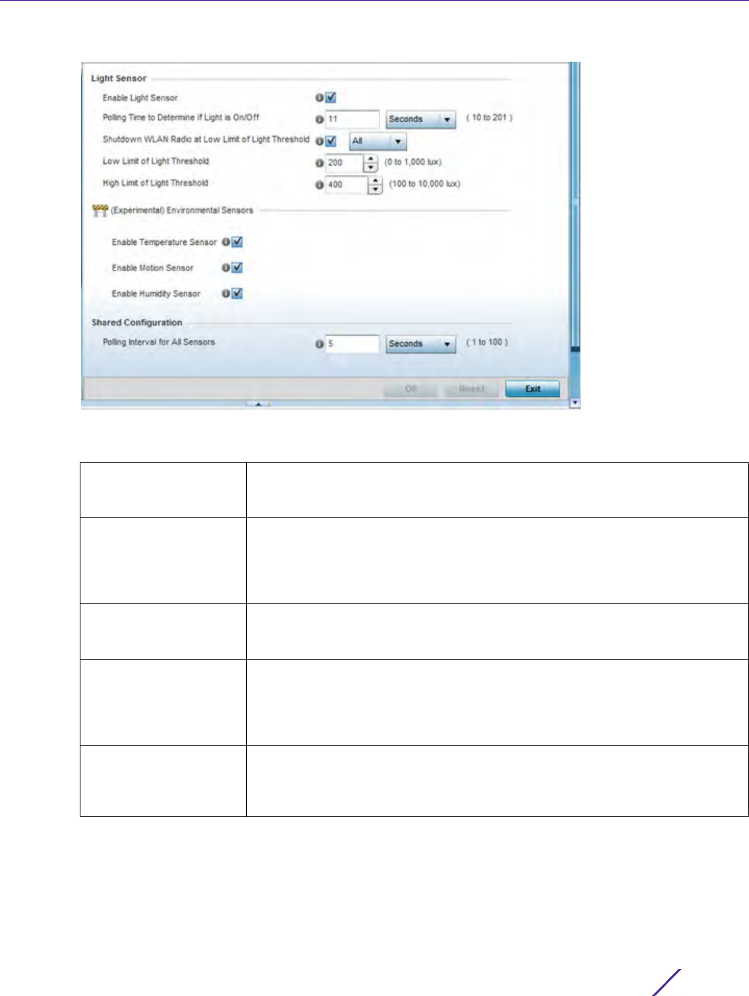
Device Configuration
Wireless Controller and Service Platform System Reference Guide 5 - 255
Figure 5-148 Profile Overrides - Environmental Sensor screen
4 Set the following Light Sensor settings for the sensor module:
Enable Light Sensor Select this option to enable the light sensor on the module. This setting is
enabled by default. The light sensor reports whether the deployment location
has its lights powered on or off.
Polling Time to
Determine if Light is
On/Off
Define an interval in Seconds (2 - 201) or Minutes (1 - 4) for the sensor module
to poll its environment to assess light intensity to determine whether lighting is
on or off. The default polling interval is 11 seconds. Light intensity is used to
determine whether the Access Point’s deployment location is currently
populated with clients.
Shutdown WLAN Radio
at Low Limit of Light
Threshold
Select this option to power off the Access Point’s radio if the light intensity
dims below the set threshold. If enabled, select All (both radios), radio-1 or
radio-2.
Low Limit of Light
Threshold
Set the low threshold limit (from 0 - 1,000 lux) to determine whether the
lighting is off in the Access Point’s deployment location. The default is 200. In
daytime, the light sensor's value is between 350-450. The default values for
the low threshold is 200, i.e., the radio is turned off if the average reading
value is lower than 200.
High Limit of Light
Threshold
Set the upper threshold limit (from 100 - 10,000 lux) to determine whether the
lighting is on in the Access Point’s deployment location. The default high
threshold is 400. The radios are turned on when the average value is higher
than 400.

Device Configuration
Wireless Controller and Service Platform System Reference Guide 5 - 256
5 Enable or disable the following Environmental Sensors:
6 Define or override the following Shared Configuration settings:
7Select
OK to save the changes and overrides made to the environmental sensor screen. Select Reset to revert
to the last saved configuration.
5.2.9.15 Overriding a Profile’s Advanced Configuration
Profile Overrides
Refer to profile’s advanced set of configuration screens to set client load balance calculations and ratios, set a
MiNT configuration and set other miscellaneous settings. For more information, refer to the following:
•Advanced Profile Client Load Balance Configuration
•Advanced MiNT Protocol Configuration
•Advanced Profile Miscellaneous Configuration
5.2.9.15.8 Advanced Profile Client Load Balance Configuration
Overriding a Profile’s Advanced Configuration
Set a the ratios and calculation values used by Access Points to distribute client loads both amongst neighbor
devices and the 2.4 and 5 GHz radio bands.
To define Access Point client load balance algorithms:
1 Select the Configuration > Devices from the Web UI.
2Select
Profile Overrides to expand its menu items
3Select
Advanced to expand its sub menu items.
4Select
Client Load Balancing from the Advanced menu item.
Enable Temperature
Sensor
Select this option to enable the module’s temperature sensor. Results are
reported back to the Access Point’s Environment screens within the Statistics
node. This setting is enabled by default.
Enable Motion Sensor Select this option to enable the module’s motion sensor. Results are reported
back to the Access Point’s Environment screens within the Statistics node. This
setting is enabled by default.
Enable Humidity Sensor Select this option to enable the module’s humidity sensor. Results are reported
back to the Access Point’s Environment screens within the Statistics node. This
setting is enabled by default.
Polling Interval for All
Sensors
Set an interval in either Seconds (1 - 100) or Minutes (1 - 2) for the time
between sensor environmental polling (both light and environment). The
default setting is 5 seconds.
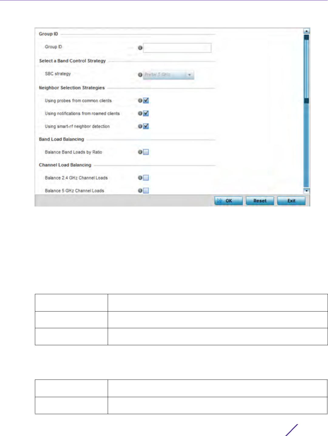
Device Configuration
Wireless Controller and Service Platform System Reference Guide 5 - 257
Figure 5-149 Advanced Profile Overrides - Client Load Balancing screen
5Use the Group ID field to define a group ID of up to 32 characters to differentiate the ID from others with
similar configurations.
6 Select the SBC strategy from the drop-down menu to determine how band steering is conducted.
Band steering directs 5 GHz-capable clients to that band. When an Access Point hears a request from a client
to associate on both the 2.4 GHz and 5 GHz bands, it knows the client is capable of operation in 5 GHz. Band
steering steers the client by responding only to the 5 GHz association request and not the 2.4 GHz request. The
client only associates in the 5 GHz band.
7 Set the following Neighbor Selection Strategies:
8Enable
Balance Band Loads by Radio (within the Band Load Balancing field) to distribute an Access Points
client traffic load across both the 2.4 and 5 GHz radio bands.
9 Set the following Channel Load Balancing settings:
Using probes from
common clients
Select this option to select neighbors (peer devices) using probes from
common clients. This setting is enabled by default.
Using notifications from
roamed clients
Select this option to select neighbors (peer devices) using roam notifications
from roamed clients. This setting is enabled by default.
Using smart-rf neighbor
detection
Select this option to select neighbors (peer devices) using Smart RF. This
setting is enabled by default.
Balance 2.4 GHz
Channel Loads
Select this option to balance an Access Point’s 2.4 GHz client load across all
channels. This setting is enabled by default.
Balance 5 GHz Channel
Loads
Select this option to balance an Access Point’s 5 GHz client load across all
channels. This setting is enabled by default.

Device Configuration
Wireless Controller and Service Platform System Reference Guide 5 - 258
10 Enable Balance AP Loads (within the AP Load Balancing field) to distribute client traffic evenly amongst
neighbor Access Points.
11 Set the following Advanced Parameters for client load balancing:
12 Define the following AP Load Balancing settings:
13 Set the following Band Control values:
Max. 2.4 GHz Difference
Considered Equal
Set the maximum load difference (from 1 - 100%) considered equal when
comparing 2.4 GHz client loads. The default setting is 1%.
Min. Value to Trigger
2.4 Ghz Channel
Balancing
Set the threshold (from 1 - 100%) beyond which channel load balancing is
triggered in the 2.4 GHz radio band. The default setting is 5%.
Weightage given to
Client Count
Set the weightage (from 1- 100%) applied to client count calculations in the 2.4
GHz radio band. The default setting is 90%.
Weightage given to
Throughput
Set the weightage (from 1- 100%) applied to client throughput calculations in
the 2.4 GHz radio band. The default setting is 10%.
Max. 5 GHz Difference
Considered Equal
Set the maximum load difference (from 1 - 100%) considered equal when
comparing 5 GHz client loads. The default setting is 1%.
Min. Value to Trigger 5
Ghz Channel Balancing
Set the threshold (from 1 - 100%) beyond which channel load balancing is
triggered in the 5 GHz radio band. The default setting is 5%.
Weightage given to
Client Count
Set the weightage (from 1- 100%) applied to client count calculations in the 5
GHz radio band. The default setting is 90%.
Weightage given to
Throughput
Set the weightage (from 1- 100%) applied to client throughput calculations in
the 5 GHz radio band. The default setting is 10%.
Min. Value to Trigger
Balancing
Set a value (from 1 - 100%) used to trigger client load balancing when
exceeded. The default setting is 5%.
Max. AP Load
Difference Considered
Equal
Set the maximum load balance differential (from 1 - 100%) considered equal
when comparing neighbor Access Point client loads. The default setting is 1%.
Weightage given to
Client Count
Set the weightage (from 1- 100%) applied to client count in an Access Point’s
overall load calculation. The default setting is 90%.
Weightage given to
Throughout
Set the weightage (from 1- 100%) applied to client throughput in an Access
Point’s overall load calculation. The default setting is 10%.
Max. Band Load
Difference Considered
Equal
Set the maximum load difference (from 1 - 100%) considered equal when
comparing band loads. The default setting is 1%.
Band Ratio (2.4 GHz) Set the relative load for the 2.4 GHz radio band as a leveled ratio from 1 - 10.
The default setting is 0.
Band Ratio (5 GHz) Set the relative load for the 5 GHz radio band as a leveled ratio from 1 - 10. The
default setting is 0.
5 GHz load at which
both bands enabled
Define the 5 GHz radio load value (from 1 - 100%) above which the 5 GHz radio
is equally preferred in the overall load balance distribution. The default is 75%.
2.4 GHz load at which
both bands enabled
Define the 2.4 GHz radio load value (from 1 - 100%) above which the 2.4 GHz
radio is equally preferred in the overall load balance distribution. The default is
75%.

Device Configuration
Wireless Controller and Service Platform System Reference Guide 5 - 259
14 Define the following Neighbor Selection settings
15 Select OK to save the changes made to the profile’s Advanced client load balance configuration. Select Reset to
revert to the last saved configuration.
5.2.9.15.9 Advanced MiNT Protocol Configuration
Overriding a Profile’s Advanced Configuration
MINT provides the means to secure profile communications at the transport layer. Using MINT, a device can be
configured to only communicate with other authorized (MINT enabled) devices. Keys can also be generated
externally using any application (like openssl). These keys must be present on the device managing the domain for
key signing to be integrated with the UI. A device needing to communicate with another first negotiates a security
context with that device.
The security context contains the transient keys used for encryption and authentication. A secure network requires
users to know about certificates and PKI. However, administrators do not need to define security parameters for
Access Points to be adopted (secure WISPe being an exception, but that isn’t a commonly used feature). Also,
users can replace any device on the network or move devices around and they continue to work. Default security
parameters for MiNT are such that these scenarios continue to function as expected, with minimal user
intervention required only when a new network is deployed
To define or override a profile’s MINT configuration:
1 Select the Configuration > Devices from the Web UI.
2Select
Profile Overrides to expand its menu items
3Select
Advanced to expand its sub menu items.
4Select
MINT Protocol from the Advanced menu item.
Minimal signal strength
for common clients
Define the minimum signal strength value (from -100 to 30 dBm) that must be
exceeded for an Access Point’s detected client to be considered a common
client. The default setting is -100 dBi.
Minimum number of
clients seen
Set the minimum number of clients (from 0 - 256) that must be common to
two or more Access Points for the Access Points to regard one another as
neighbors using the common client neighbor detection strategy. The default
setting is 0.
Max confirmed
neighbors
Set the maximum number (from 1 - 16) of neighbor Access Points that must be
detected amongst peer Access Point to initiate load balancing. The default
setting is 16.
Minimum signal
strength for smart-rf
neighbors
Set the minimal signal strength value (from -100 to 30 dBm) for an Access
Point detected using Smart RF to qualify as a neighbor Access Point. The
default setting is - 65 dBm.
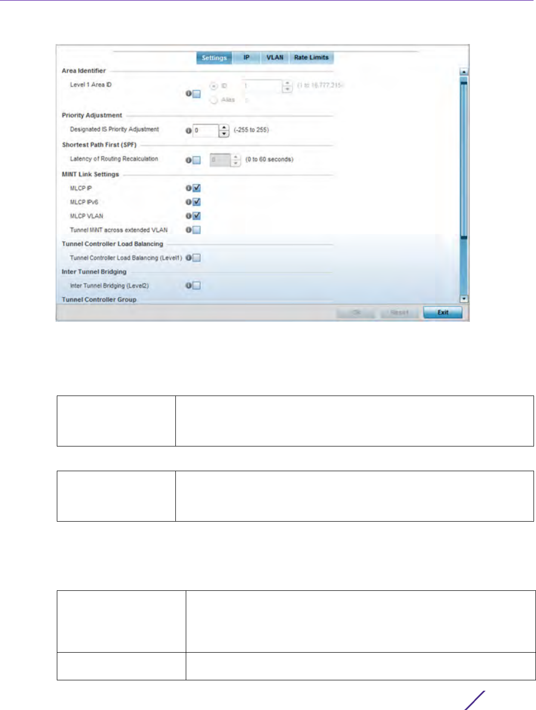
Device Configuration
Wireless Controller and Service Platform System Reference Guide 5 - 260
Figure 5-150 Advanced Profile Overrides MINT screen - Settings tab
The Settings tab displays by default.
5 Refer to the Area Identifier field to define or override the Level 1 and Level 2 Area IDs used by the profile’s MINT
configuration.
6 Define or override the following Priority Adjustment in respect to devices supported by the profile:
7 Select the Latency of Routing Recalculation option (within the Shortest Path First (SPF) field) to enable the
spinner control used for defining or overriding a latency period (from 0 - 60 seconds). The default setting is
disabled.
8 Define or override the following MINT Link Settings in respect to devices supported by the profile:
Level 1 Area ID Select this option to either use a spinner control for setting the Level 1 Area ID
(1 - 16,777,215) or create an alias for the ID. An alias enables an administrator to
define a configuration item, such as a this area ID, as an alias once and use the
alias across different configuration items. The default value is disabled.
Designated IS Priority
Adjustment
Use the spinner control to set a Designated IS Priority Adjustment setting. This
is the value added to the base level DIS priority to influence the Designated IS
(DIS) election. A value of +1 or greater increases DISiness. The default setting is
0.
MLCP IP Check this box to enable MINT Link Creation Protocol (MLCP) by IP Address.
MLCP is used to create one UDP/IP link from the device to a neighbor. The
neighboring device does not need to be a controller or service platform, it
can be another Access Point with a path to the controller or service platform.
This setting is enabled by default.
MLCP IPv6 Check this box to enable MLCP for automated MiNT UDP/IP link creation. This
setting is enabled by default.
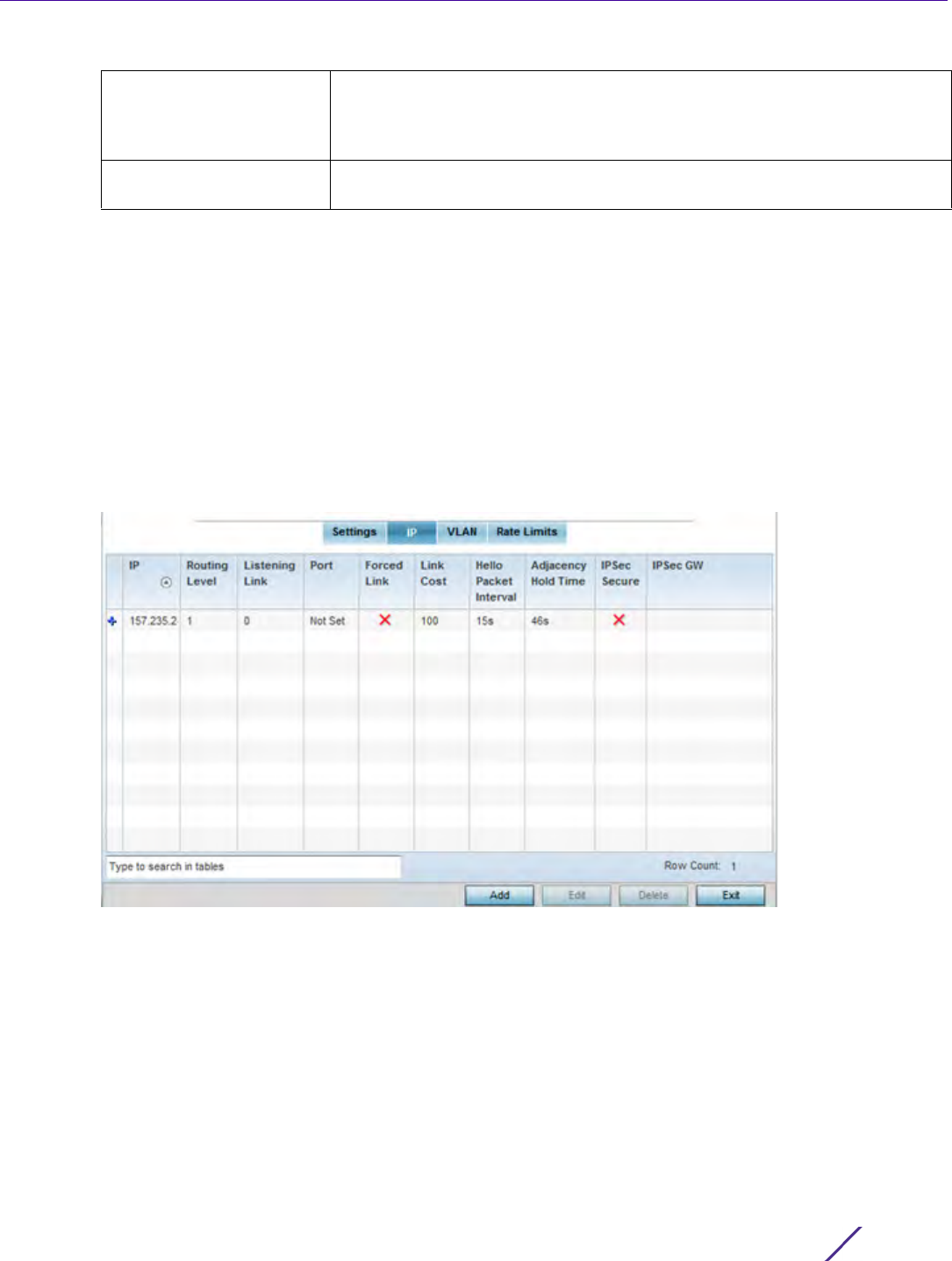
Device Configuration
Wireless Controller and Service Platform System Reference Guide 5 - 261
9Select
Tunnel Controller Load Balancing (Level 1) to enable load balance distribution via a WLAN tunnel
controller. This setting is disabled by default.
10 Select Inter Tunnel Bridging (Level 2) to enable inter tunnel bridging. This setting is disabled by default.
11 Enter a 64 character maximum Tunnel Controller Name for this tunneled-WLAN-controller interface.
12 Enter a 64 character maximum Preferred Tunnel Controller Name this Access Point prefers to tunnel traffic to
via an extended VLAN.
13 Select OK to save the updates and overrides to the MINT Protocol configuration. Select Reset to revert to the
last saved configuration.
14 Select the IP tab to display the link IP network address information shared by the devices managed by the
MINT configuration.
Figure 5-151 Advanced Profile MINT screen - IP tab
15 The IP tab displays the IP address, Routing Level, Listening Link, Port, Forced Link, Link Cost, Hello Packet
Interval, Adjacency Hold Time and IPSec Secure, and IPSec GW settings that devices use to securely
communicate amongst one another. Select Add to create a new Link IP configuration or Edit to override an
existing MINT configuration.
MLCP VLAN Check this box to enable MLCP by VLAN. MLCP is used to create one VLAN
link from the device to a neighbor. That neighboring device does not need to
be a controller or service platform, it can be another Access Point with a path
to the controller or service platform. This setting is enabled by default.
Tunnel MiNT across
extended VLAN
Select this option to tunnel MiNT protocol packets across an extended VLAN.
This setting is disabled by default.
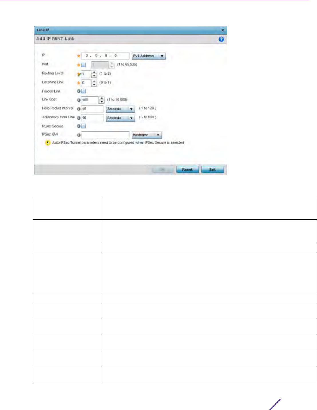
Device Configuration
Wireless Controller and Service Platform System Reference Guide 5 - 262
Figure 5-152 Advanced Profile MINT screen - Link IP tab
16 Set the following Link IP parameters to complete the MINT network address configuration:
IP Define or override the IP address used by peers for interoperation when
supporting the MINT protocol. Use the drop-down to select the type of IP address
provided. The available choices are IPv4 Address and IPv6 Address.
Port To specify a custom port for MiNT links, select this option and use the spinner
control to define or override the port number
(1 - 65,535).
Routing Level Use the spinner control to define or override a routing level of either 1 or 2.
Listening Link Specify a listening link of either 0 or 1. UDP/IP links can be created by configuring
a matching pair of links, one on each end point. However, that is error prone and
doesn’t scale. So UDP/IP links can also listen (in the TCP sense), and dynamically
create connected UDP/IP links when contacted. The typical configuration is to
have a listening UDP/IP link on the IP address S.S.S.S, and for all the APs to have a
regular UDP/IP link to S.S.S.S.
Forced Link Check this box to specify the MiNT link as a forced link.
Link Cost Use the spinner control to define or override a link cost from
1 - 10,000. The default value is 100.
Hello Packet Interval Set or override an interval in either Seconds (1 - 120) or Minutes (1 - 2) for the
transmission of hello packets. The default interval is 15 seconds.
Adjacency Hold Time Set or override a hold time interval in either Seconds (2 - 600) or Minutes (1 - 10)
for the transmission of hello packets. The default interval is 46 seconds.
IPSec Secure Enable this option to provide IPSec secure peer authentication on the MiNT
connection (link). This option is disabled by default.
IPSec GW Select the numerical IP address or administrator defined hostname of the IPSec
gateway. Hostnames cannot include an underscore character.
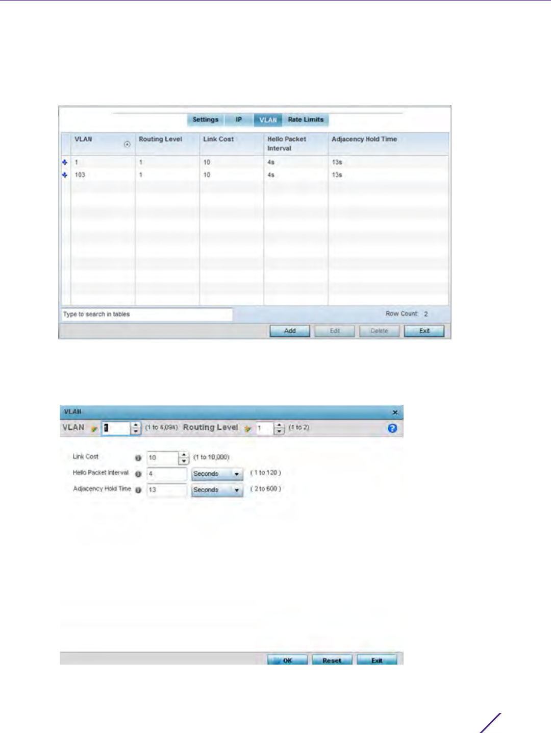
Device Configuration
Wireless Controller and Service Platform System Reference Guide 5 - 263
17 Select OK to save the updates and overrides to the MINT Protocol’s network address configuration. Select Reset
to revert to the last saved configuration.
18 Select the VLAN tab to display link IP VLAN information shared by the devices managed by the MINT
configuration.
Figure 5-153 Advanced Profile MINT screen - VLAN tab
The VLAN tab displays the VLAN, Routing Level, Link Cost, Hello Packet Interval and Adjacency Hold Time
devices use to securely communicate amongst one another. Select Add to create a new VLAN link
configuration or Edit to override an existing MINT VLAN configuration.
Figure 5-154 Advanced Profile MINT screen - Add/Edit VLAN
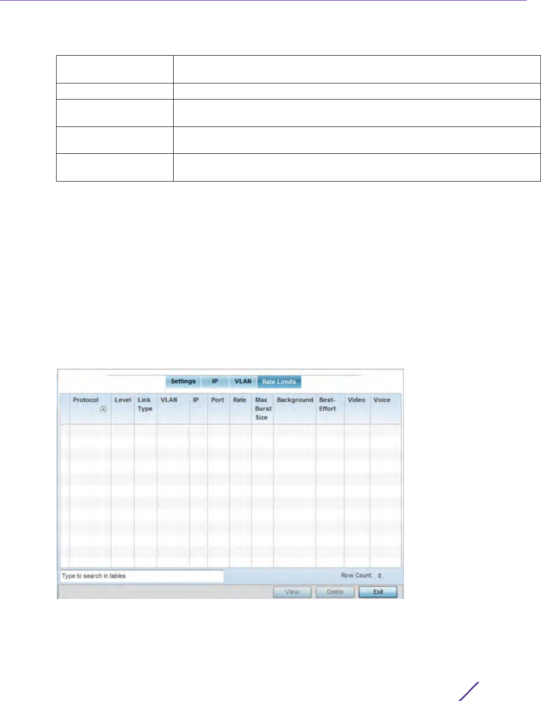
Device Configuration
Wireless Controller and Service Platform System Reference Guide 5 - 264
19 Set the following VLAN parameters for the MINT configuration:
20 Select OK to save the updates and overrides to the MINT Protocol configuration. Select Reset to revert to the
last saved configuration.
21 Select the Rate Limits tab to display data rate limits configured on extended VLANs and optionally add or edit
rate limit configurations.
Excessive traffic can cause performance issues on an extended VLAN. Excessive traffic can be caused by
numerous sources including network loops, faulty devices or malicious software such as a worm or virus that
has infected on one or more devices. Rate limiting reduces the maximum rate sent or received per wireless
client. It prevents any single user from overwhelming the wireless network. It can also provide differential
service for service providers. Uplink and downlink rate limits are usually configured on a RADIUS server using
vendor specific attributes. Rate limits are extracted from the RADIUS server’s response. When such attributes
are not present, the settings defined on the controller, service platform or Access Point are applied. An
administrator can set separate QoS rate limit configurations for data types transmitted from the network
(upstream) and data transmitted from a wireless clients back to associated radios (downstream).
Figure 5-155 Advanced Profile MINT screen - Rate Limit tab
Existing rate limit configurations display along with their virtual connection protocols and data traffic QoS
customizations.
22 Select Add to create a new rate limit configuration.
VLAN Define a VLAN ID from 1 - 4,094 used by peers for interoperation when
supporting the MINT protocol.
Routing Level Use the spinner control to define or override a routing level of either 1 or 2.
Link Cost Use the spinner control to define or override a link cost from 1 - 10,000. The
default value is 100.
Hello Packet Interval Set or override an interval in either Seconds (1 - 120) or Minutes (1 - 2) for the
transmission of hello packets. The default interval is 15 seconds.
Adjacency Hold Time Set or override a hold time interval in either Seconds (2 - 600) or Minutes (1 - 10)
for the transmission of hello packets. The default interval is 46 seconds.
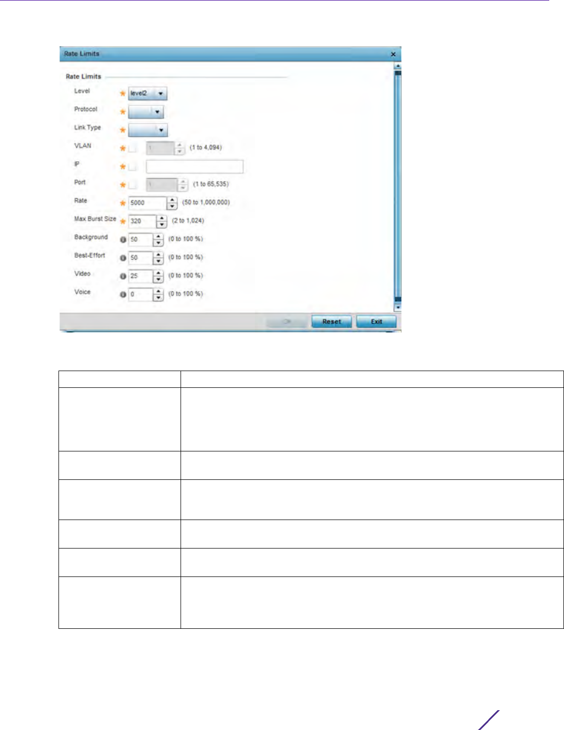
Device Configuration
Wireless Controller and Service Platform System Reference Guide 5 - 265
Figure 5-156 Advanced Profile MINT screen - Add/Edit Rate Limit
23 Set the following Rate Limits to complete the MINT configuration:
Level Select level2 to apply rate limiting for all links on level2.
Protocol Select either mlcp or link as this configuration’s rate limit protocol. Mint Link
Creation Protocol (MLCP) creates a UDP/IP link from the device to a neighbor. The
neighboring device does not need to be a controller or service platform, it can be
an Access Point with a path to the controller or service platform. Select link to
rate limit using statically configured MiNT links.
Link Type Select either VLAN, to configure a rate limit configuration on a specific virtual
LAN, or IP to set rate limits on a static IP address/Port configuration.
VLAN When the Protocol is set to link and the Link Type is set to VLAN, use the spinner
control to select a virtual LAN from 1 - 4094 to refine the rate limiting
configuration to a specific VLAN.
IP When the Protocol is set to link and the Link Type is set to VLAN, enter the IP
address as the network target for rate limiting.
Port When the Protocol is set to link and the Link Type is set to VLAN, use the spinner
control to set the virtual port (1 - 65,535) used for rate limiting traffic.
Rate Define a rate limit between 50 - 1,000,000 kbps. This limit constitutes a threshold
for the maximum the number of packets transmitted or received (from all access
categories). Traffic that exceeds the defined rate is dropped and a log message is
generated. The default setting is 5000 kbps.

Device Configuration
Wireless Controller and Service Platform System Reference Guide 5 - 266
24 Select OK to save the updates and overrides to the MINT Protocol’s rate limit configuration. Select Reset to
revert to the last saved configuration.
5.2.9.15.10 Advanced Profile Miscellaneous Configuration
Overriding a Profile’s Advanced Configuration
Refer to the advanced profile’s Miscellaneous menu item to set or override a profile’s NAS configuration. The
profile database on the RADIUS server consists of user profiles for each connected network access server (NAS)
port. Each profile is matched to a username representing a physical port. When the wireless controller authorizes
users, it queries the user profile database using a username representative of the physical NAS port making the
connection. Access Point LED behavior and RF Domain management can also be defined from within the
Miscellaneous screen.
1 Select the Configuration > Devices from the Web UI.
2Select
Profile Overrides to expand its menu items
3Select
Advanced to expand its sub menu items.
4Select
Miscellaneous from the Advanced menu item.
Max Burst Size Use the spinner to set the maximum burst size from 0 - 1024 kb. The smaller the
burst, the less likely the upstream packet transmission will result in congestion for
the WLAN’s client destinations. By trending the typical number of ARP, broadcast,
multicast and unknown unicast packets over a period of time, the average rate for
each access category can be obtained. Once a baseline is obtained, administrators
should add a 10% margin (minimally) to allow for traffic bursts. The default burst
size is 320 kbytes.
Background Configures the random early detection threshold (as a percentage) for low priority
background traffic. Background packets are dropped and a log message
generated if the rate exceeds the set value. Background traffic consumes the least
bandwidth of any access category, so this value can be set to a lower value once a
general upstream rate is known by the network administrator (using a time trend
analysis). The default setting
is 50%.
Best-Effort Configures the random early detection threshold (as a percentage) for low priority
best-effort traffic. Best-effort packets are dropped and a log message generated if
the rate exceeds the set value. Best effort traffic consumes little bandwidth, so
this value can be set to a lower value once a general upstream rate is known by
the network administrator (using a time trend analysis).The default setting is 50%.
Video Configures the random early detection threshold (as a percentage) for high
priority video traffic. Video packets are dropped and a log message generated if
the rate exceeds the set value. Video traffic consumes significant bandwidth, so
this value can be set to a higher value once a general upstream rate is known by
the network administrator (using a time trend analysis).The default setting is 25%.
Voice Configures the random early detection threshold (as a percentage) for high
priority voice traffic. Voice packets are dropped and a log message generated if
the rate exceeds the set value. Voice applications consume significant bandwidth,
so this value can be set to a higher value once a general upstream rate is known
by the network administrator (using a time trend analysis).The default setting is
0%.
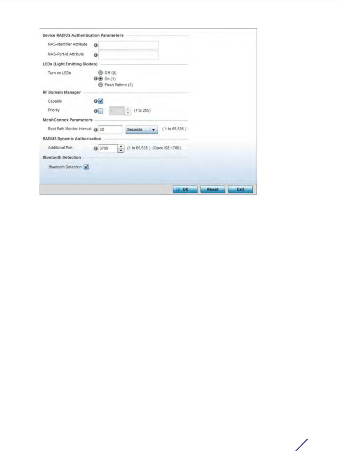
Device Configuration
Wireless Controller and Service Platform System Reference Guide 5 - 267
Figure 5-157 Advanced Profile Overrides - Miscellaneous screen
5Set a NAS-Identifier Attribute up to 253 characters in length.
6 This is the RADIUS NAS-Identifier attribute that typically identifies the controller, service platform or Access
Point where a RADIUS message originates.
7Set a NAS-Port-Id Attribute up to 253 characters in length.
8 This is the RADIUS NAS port ID attribute which identifies the device port where a RADIUS message originates.
9 Select the Turn on LEDs option (within the LEDs (Light Emitting Diodes) section) to enable the LEDs on Access
Point. This parameter is not available for controllers or service platforms.
Select the Flash Pattern(2) option (within the LEDs (Light Emitting Diodes) field) to flash an Access Point’s
LED’s in a distinct manner (different from its operational LED behavior) to allow an administrator to validate an
Access Point has received its configuration from its managing controller or service platform.
Enabling this feature allows an administrator to validate an Access Point has received its configuration
(perhaps remotely at the site of deployment) without having to log into the managing controller or service
platform. This feature is disabled by default.
10 Select the Capable check box (within the RF Domain Manager section) to designate this specific device as being
the RF Domain manager for a particular RF Domain. The default value is enabled.
11 Select the Priority check box (within the RF Domain Manager section) to set a priority value for this specific
profile managed device. Once enabled, use the spinner control to set a device priority between 1 - 255. The
higher the number set, the higher the priority in the RF Domain manager election process.
12 Configure a Root Path Monitor Interval (from1 - 65,535 seconds) to specify how often to check if the mesh point
is up or down.
13 Set the Additional Port value (within the RADIUS Dynamic Authorization field) from 1-65,535 to enable a CISCO
Identity Services Engine (ISE) Authentication, Authorization and Accounting (AAA) server to dynamically
authenticate a client.

Device Configuration
Wireless Controller and Service Platform System Reference Guide 5 - 268
When a client requests access to a CISCO ISE RADIUS server supported network, the server presents the client
with a URL where a device’s compliance is checked for definition file validity (this form of file validity checking
is called posture). If the client device complies, it is allowed access to the network.
14 Enable Bluetooth Detection to scan for Bluetooth devices over the WiNG managed 2.4 GHz Access Point radio.
Bluetooth is a technology for exchanging data over short distances using short-wavelength UHF radio waves in
the 2.4 GHz band from mobile wireless clients.
15 Select OK to save the changes made to the profile’s Advanced Miscellaneous configuration. Select Reset to
revert to the last saved configuration.
5.3 Auto Provisioning Policies
Device Configuration
Wireless devices can adopt other wireless devices. For example, a wireless controller can adopt an number of
Access Points. When a device is adopted, the device configuration is determined by the adopting device. Since
multiple configuration policies are supported, an adopting device needs to determine which configuration policies
should be used for a given adoptee. Auto Provisioning Policies determine which configuration policies are used for
an adoptee based on some of its properties. For example, a configuration policy could be assigned based on MAC
address, IP address, CDP snoop strings, etc.
Once created an auto provisioning policy can be used in profiles or device configuration objects. An auto
provisioning policy contains a set of ordered by precedence rules that either deny or allow adoption based on
potential adoptee properties and a catch-all variable that determines if the adoption should be allowed when none
of the rules is matched. All rules (both deny and allow) are evaluated sequentially starting with the rule with the
lowest precedence. The evaluation stops as soon as a rule has been matched, no attempt is made to find a better
match further down in the set.
The evaluation is performed using various matching criteria. The matching criteria supported include:
NOTE: Enabling Bluetooth detection results in interference on the Access Point’s
2.4 GHz radio when in WLAN mode. WLANs are susceptible to sources of
interference by Bluetooth devices.
MAC Matches the MAC address of a device attempting to be adopted. Either a single
MAC address or a range of MAC addresses can be specified.
VLAN Matches when adoption over a Layer 2 link matches the VLAN ID of an adoption
request. Note that this is a VLAN ID as seen by the recipient of the request, in
case of multiple hops over different VLANs this may different from VLAN ID set
by the sender. A single VLAN ID is specified in the rule. This rule is ignored for
adoption attempts over Layer 3.
IP Address Matches when adoption is using a Layer 3 link matches the source IP address of
an adoption request. In case of NAT the IP address may be different from what
the sender has used. A single IP, IP range or IP/mask is specified in the rule. This
rule is ignored for adoption attempts over Layer 2.
Serial Number Matches exact serial number (case insensitive).
Model Matches exact model name (case insensitive).
Device Configuration
Wireless Controller and Service Platform System Reference Guide 5 - 269
Auto Provisioning is the process to discover controllers or service platforms available in the network, pick the most
desirable controller or service platform, establish an association, optionally obtain an image upgrade and obtain its
configuration.
At adoption, an Access Point solicits and receives multiple adoption responses from controllers and service
platforms available on the network. These adoption responses contain loading policy information the Access Point
uses to select the optimum controller or service platform for adoption. By default, an auto provisioning policy
generally distributes AP adoption evenly amongst available controller or service platform. Modify existing adoption
policies or create a new one as needed to meet the adoption requirements of a device and their assigned profile.
An auto provisioning policy enables an administrator to define adoption rules an Access Point’s adoption by a
wireless controller.
Auto provisioning policies set the different restrictions on how an Access Point gets adopted to a wireless
controller.
To review existing Auto Provisioning Policy configurations:
1Select
Configuration > Devices > Auto Provisioning Policy.
2The
Auto-Provisioning screen displays by default.
DHCP Option Matches the value found in DHCP vendor option 191 (case insensitive). DHCP
vendor option 191 can be setup to communicate various configuration parameters
to an AP. The value of the option in a string in the form of tag=value separated by
a semicolon, e.g.’tag1=value1;tag2=value2;tag3=value3’. The access point includes
the value of tag’rf-domain’, if present. This value is matched against the auto
provisioning policy.
FQDN Matches a substring to the FQDN of a device (case insensitive).
CDP Matches a substring in a list of CDP snoop strings (case insensitive). For example,
if an Access Point snooped 3 devices: controller1.extremenetworks.com,
controller2.extremenetworks.com and
controller3.extremenetworks.com,’controller1’,’extremenetworks’,
’extremenetworks.com’, are examples of the substrings that will match.
LLDP Matches a substring in a list of LLDP snoop strings (case insensitive). For
example, if an Access Point snooped 3 devices: controller1.extremenetworks.com,
controller2.extremenetworks.com and
controller3.extremenetworks.com,’controller1’, ’extremenetworks’,
’extremenetworks.com’, are substrings match.
NOTE: A device configuration does not need to be present for an auto provisioning
policy to take effect. Once adopted, and the device’s configuration is defined and
applied by the controller or service platform, the auto provisioning policy mapping
does not have impact on subsequent adoptions by the same device.
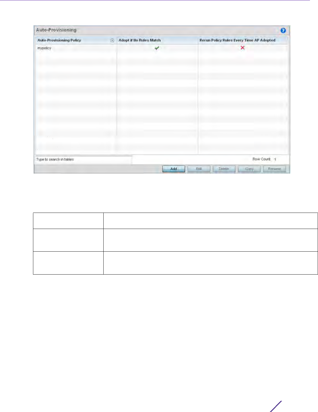
Device Configuration
Wireless Controller and Service Platform System Reference Guide 5 - 270
Figure 5-158 Auto-Provisioning screen
Use the Auto-Provisioning screen to determine whether an existing policy can be used as is, a new Auto
Provisioning Policy requires creation or an existing policy requires edit or deletion.
3 Review the following Auto-Provisioning parameters:
4Select
Add to create a new Auto Provisioning Policy, Edit to revise an existing Auto Provisioning Policy or
Delete to permanently remove a policy. For instructions on either adding or editing an Auto Provisioning Policy,
see Configuring an Auto-Provisioning Policy on page 5-270.
5.3.1 Configuring an Auto-Provisioning Policy
Cluster Configuration Overrides (Controllers and Service Platforms Only)
Auto-Provisioning Policies can be created or refined as unique deployment requirements dictate changes in the
number of Access Point radios within a specific radio coverage area.
To add a new Auto Provisioning Policy or edit an existing Auto-Provisioning Policy configuration:
Auto-Provisioning Policy Lists the name of each policy when it was created. It cannot be modified as part
of the Auto Provisioning Policy’s edit process.
Adopt if No Rules Match Displays whether this policy will adopt devices if no adoption rules apply. Double-
click within this column to launch the edit screen where rules can be defined for
device adoption. This feature is disabled by default.
Rerun Policy Rules Every
Time AP Adopted
Displays whether this policy will be run every time an AP is adopted. Double-click
within this column to launch the edit screen where this option can be modified.
This feature is disabled by default.
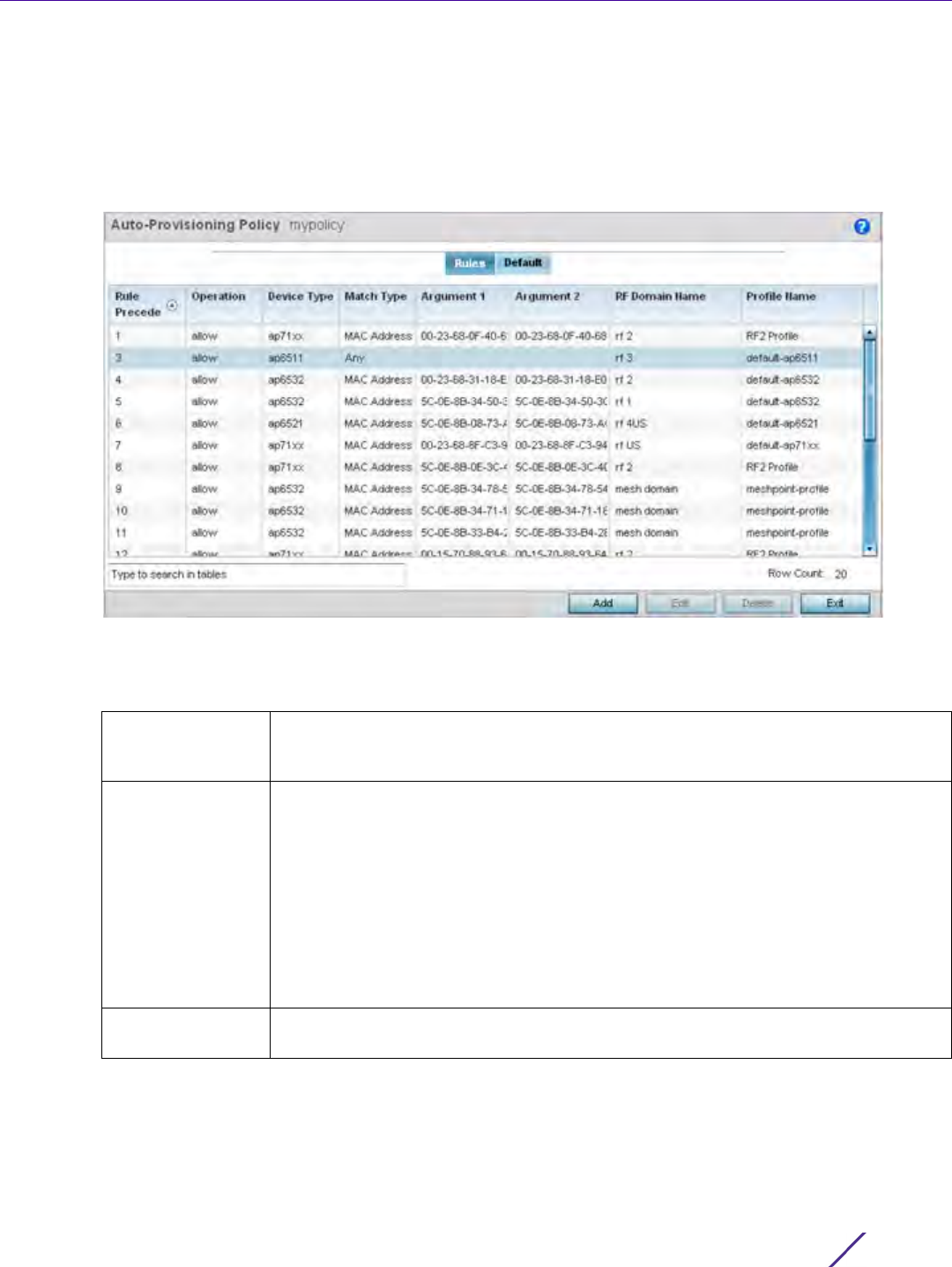
Device Configuration
Wireless Controller and Service Platform System Reference Guide 5 - 271
1From the Adoption screen, either select Add or select an existing Auto-Provisioning Policy and select Edit.
2 If adding a new Auto-Provisioning Policy, provide a name in the Auto-Provisioning Policy field. The name must
not exceed 32 characters. Select Continue to enable the remaining parameters of the Auto-Provisioning Policy
screen.
The Rules tab displays by default.
Figure 5-159 Auto-Provisioning Policy screen - Rules tab
3 Review the following Auto-Provisioning Policy rule data to determine whether a rule can be used as is, requires
edit or whether new rules need to be defined:
Rule Precedence Displays the precedence (sequence) the Adoption Policies rules are applied. Rules
with the lowest precedence receive the highest priority. This value is set (from 1 -
1000) when adding a new Auto Provisioning Policy rule configuration.
Operation Lists the operation taken upon receiving an adoption request from an Access Point:
The following operations are available:
allow – Allows the normal provisioning of connected Access Points upon request.
deny – Denies (prohibits) the provisioning of connected Access Point upon request.
redirect – When selected, an Access Point seeks a steering controller (upon
adoption request), that will forward the network credentials of a designated
controller resource that initiates the provisioning process.
upgrade – Conducts the provisioning of requesting Access Points from this
controller resource.
Device Type Sets the Access Point model for which this policy applies. Adoption rules are specific
to the selected model.

Device Configuration
Wireless Controller and Service Platform System Reference Guide 5 - 272
4 If a rule requires addition or modification, select either Add or Edit to define the required parameters using the
Rule screen.
Match Type Lists the matching criteria used in the policy. This is like a filter and further refines
the APs that can be adopted. The Match Type can be one of the following:
MAC Address – The filter type is a MAC Address of the selected Access Point model.
IP Address – The filter type is the IP address of the selected Access Point model.
VLAN – The filter type is a VLAN.
Serial Number – The filter type is the serial number of the selected Access Point
model.
Model Number – The filter type is the Access Point model number.
DHCP Option – The filter type is the DHCP option value of the selected Access Point
model.
Argument 1 The number of arguments vary on the Match Type. This column lists the first
argument value. This value is not set as part of the rule creation or edit process.
Argument 2 The number of arguments vary on the Match Type. This column lists the second
argument value. This value is not set as part of the rule creation or edit process.
RF Domain Name Sets the name of the RF Domain to which the device is adopted automatically.
Select the Create icon to define a new RF Domain configuration or select the Edit
icon to revise an existing configuration.
Profile Name Defines the name of the profile used when the Auto Provisioning Policy is applied to
a device. Select the Create icon to define a new Profile configuration or the Edit icon
to revise an existing configuration. For more information, see General Profile
Configuration on page 8-5.
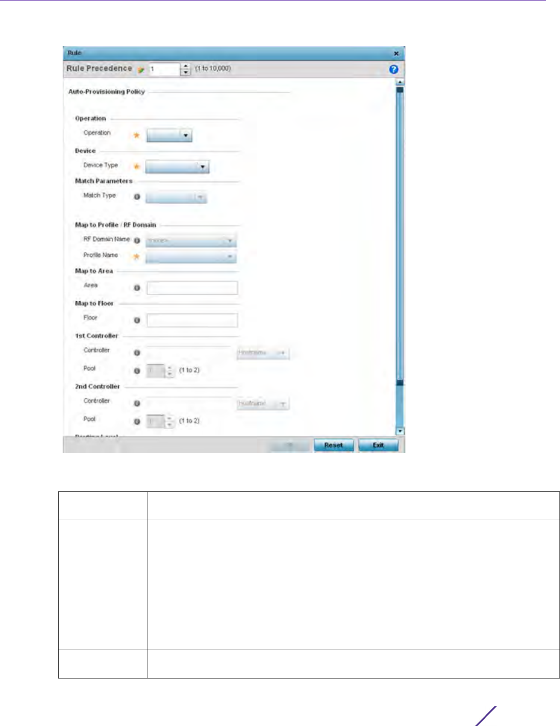
Device Configuration
Wireless Controller and Service Platform System Reference Guide 5 - 273
Figure 5-160 Auto Provisioning Policy Rule screen
5 Specify the following parameters in the Rule screen:
Rule Precedence Assign a priority from 1 - 10,000 for the application of the auto-provisioning policy rule.
Rules with thlowest value have priority.
Operation Define the operation taken upon receiving an adoption request from an Access Point: the
following operations are available:
Allow – Allows the normal provisioning of connected Access Points upon request.
Deny – Denies (prohibits) the provisioning of connected Access Point upon request.
Redirect – When selected, an Access Point seeks a steering controller (upon adoption
request), that will forward the network credentials of a designated controller resource
that initiates the provisioning process.
Upgrade – Conducts the provisioning of requesting Access Points from this controller
resource.
Device Type Set the Access Point model for which this policy applies. Adoption rules are specific to
the selected model, as radio configurations are often unique to specific models.

Device Configuration
Wireless Controller and Service Platform System Reference Guide 5 - 274
6Select
OK to save the updates and overrides to the Auto-Provisioning policy rule configuration. Select Reset to
revert to the last saved configuration.
7 Select the Default tab to define the Auto Provisioning Policy’s rule matching adoption configuration.
Match Type Set the matching criteria used in the policy. This is like a filter and further refines Access
Points capable of adoption. The Match Type can be one of the following:
MAC Address – The filter type is a MAC Address of the selected Access Point model.
IP Address – The filter type is the IP address of the selected Access Point model.
VLAN – The filter type is a VLAN.
Serial Number – The filter type is the serial number of the selected Access Point model.
Model Number – The filter type is the Access Point model number.
DHCP Option – The filter type is the DHCP option value of the selected Access Point
model.
RF Domain Name Set the RF Domain to which the device is adopted automatically. Select the Create icon
to define a new RF Domain configuration or select the Edit icon to revise an existing
configuration. For more information, see to General Profile Configuration on page 8-5.
Profile Name Define the profile used when an Auto Provisioning Policy is applied to a device. Select
the Create icon to define a new Profile configuration or select the Edit icon to revise an
existing configuration. For more information, see General Profile Configuration on page
8-5.
Area Enter a 64 character maximum deployment area name assigned to this policy.
Floor Enter a 32 character maximum deployment floor name assigned to this policy.
1st Controller When redirect is selected as the operation, provide a 1st choice steering controller
Hostname or IP Address and port to forward network credentials for a controller resource
to initiate the provisioning process.
2nd Controller When redirect is selected as the operation, provide a 2nd choice steering controller
Hostname or IP Address and port to forward network credentials for a controller resource
to initiate the provisioning process.
Routing Level When redirect is selected as the operation, specify the routing level as 1 or 2.
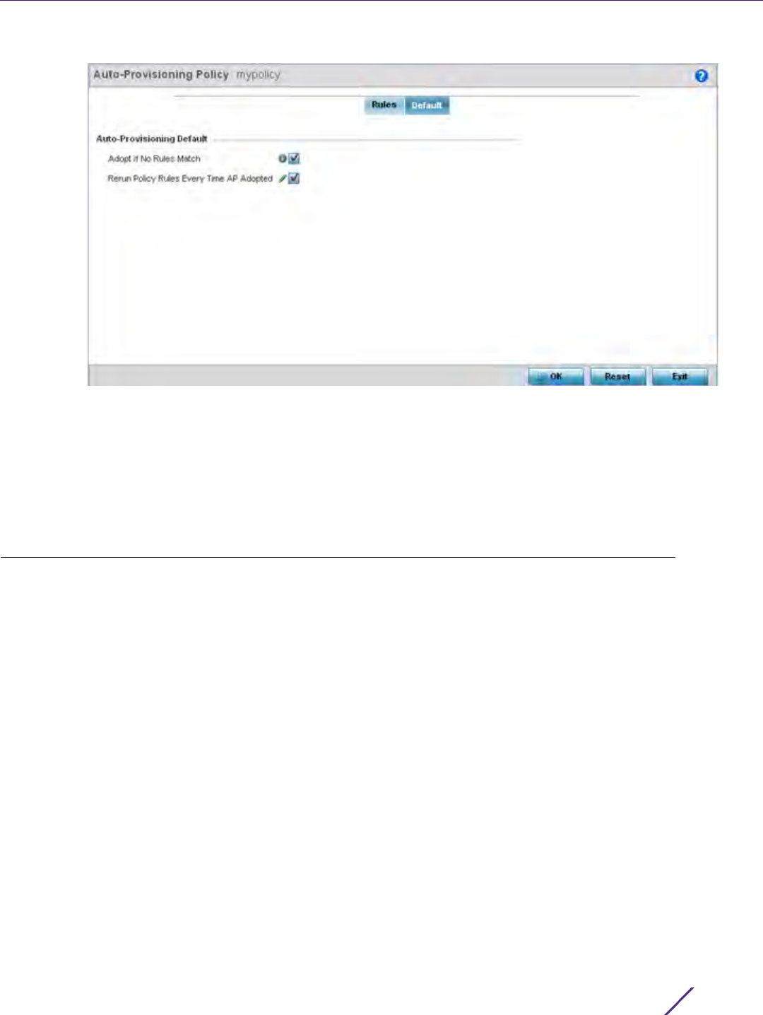
Device Configuration
Wireless Controller and Service Platform System Reference Guide 5 - 275
Figure 5-161 Auto Provisioning Policy screen - Default tab
8Select Adopt if No Rules Match to adopt when no matching filter rules apply. This setting is disabled by default.
9Select
Rerun Policy Rules Every Time AP Adopted to run this policy and apply its rule set every time an Access
Point is adopted. This setting is disabled by default.
10 Select OK to save the updates to the screen. Selecting Reset reverts the screen to the last saved configuration.
5.4 Managing an Event Policy
Device Configuration
Event Policies enable an administrator to create specific notification mechanisms using one, some or all of the
SNMP, syslog, forwarding or e-mail notification options available to the controller or service platform. Each listed
event can have customized notification settings defined and saved as part of an event policy. Thus, policies can be
configured and administrated in respect to specific sets of client association, authentication/encryption and
performance events. Once policies are defined, they can be mapped to device profiles strategically as the
likelihood of an event applies to particular devices. By default, there’s no enabled event policy and one needs to be
created and implemented.
When initially displayed, the Event Policy screen lists interfaces. Existing policies can have their event notification
configurations modified as device profile requirements warrant.
To define an event policy:
1Select
Configuration > Devices > Event Policy.
2Select
Add to create a new event policy or Edit to modify an existing policy. Use the Delete button to remove
existing event policy.
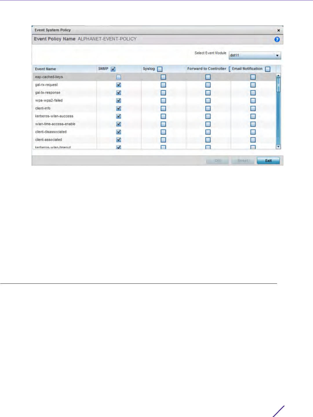
Device Configuration
Wireless Controller and Service Platform System Reference Guide 5 - 276
Figure 5-162 Event Policy screen
3 Ensure the button is selected to enable the screen for configuration for a specific event category. This option
needs to remain selected to apply the event policy configuration to the profile.
4 Refer to the Select Event Module drop-down menu on the top right-hand side of the screen and select an event
module used to track the occurrence of each list event.
5Review each event and select (or deselect) the SNMP, Syslog, Forward to Controller or Email Notification option
as required for the event. Map an existing policy to a device profile as needed. Select Profile from the Map
drop-down menu in the lower-left hand side of the screen. Expand the list of device profiles available, and
apply the event policy as required.
6Select
OK to save the changes. Select Reset to revert to the last saved configuration. Delete obsolete rows as
needed.
5.5 Managing MINT Policies
Device Configuration
To add or modify a MINT Policy:
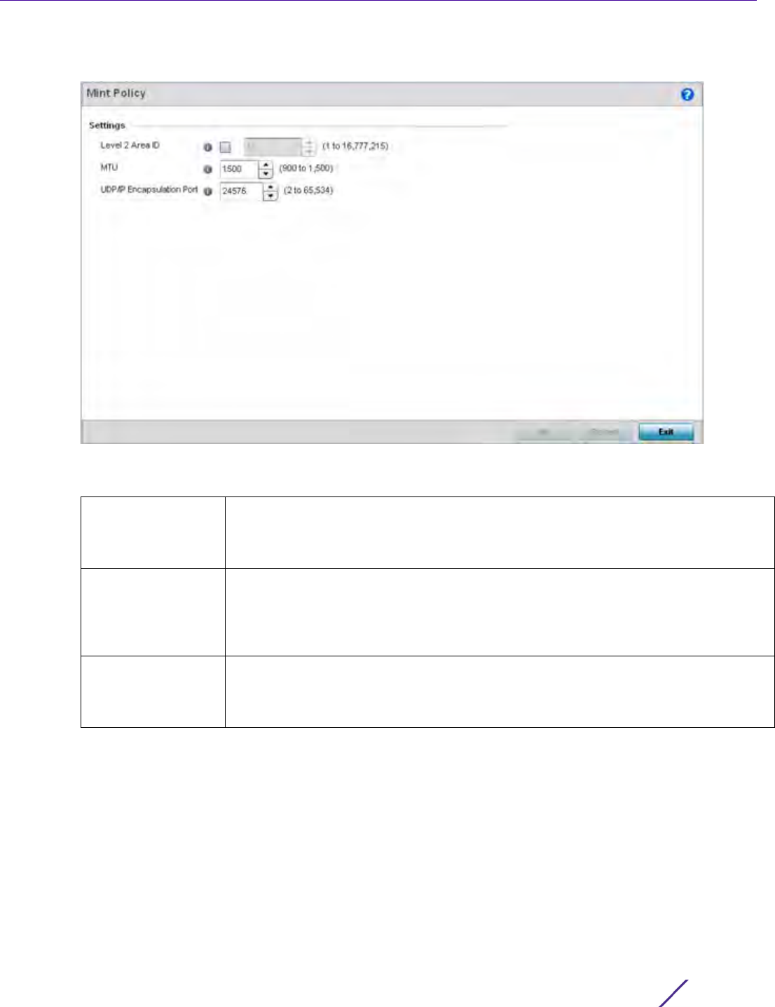
Device Configuration
Wireless Controller and Service Platform System Reference Guide 5 - 277
1Select
Configuration > Devices > MINT Policy to display the MINT Policy screen.
Figure 5-163 MINT Policy Configuration screen
2 Configure the following parameters to configure the MINT policy:
3Select
OK to save the changes. Select Reset to revert to the last saved configuration.
Level 2 Area ID Define a Level 2 Area ID for the Mint Policy. The Level 2 Area ID is the global mint
area identifier. This area identifier separates two overlapping mint networks and need
only be configured if the administrator has two mint networks that share the same
packet broadcast domain.
MTU Specify a MTU value for the mint policy between 900 and 1,500. The MTU setting
specifies the maximum packet size that will be used for mint packets. Larger packets
will be fragmented so they fit within this packet size limit. The administrator may
want to configure this parameter if the mint backhaul network requires or
recommends smaller packet sizes. The default value is 1500.
UDP/IP
Encapsulation Port
Specify the port to use for UDP/IP encapsulation between 2 and 65,534. This value
specifies an alternate UDP port to be used by mint packets and must be an even
number. This port number will be used by mint control packets, and this port value
plus 1 will be used to carry mint data packets. The default value is 24576.

6 - 1Wireless Controller and Service Platform System Reference Guide
6
Wireless Configuration
A Wireless Local Area Network (WLAN) is a data-communications system and wireless local area network that
flexibly extends the functionalities of a wired LAN. A WLAN links two or more computers or devices using spread-
spectrum or OFDM modulation based technology. A WLAN does not require lining up devices for line-of-sight
transmission, and are thus, desirable for wireless networking. Roaming users can be handed off from one wireless
controller connected Access Point to another, like a cellular phone system. WLANs can therefore be configured
around the needs of specific user groups, even when they are not in physical proximity.
WLANs can be used to provide an abundance of services, including data communications (allowing mobile devices
to access applications), E-mail, file and print services or even specialty applications (such as guest access control
and asset tracking).
Each wireless controller WLAN configuration contains encryption, authentication and QoS policies and conditions
for user connections. Connected Access Point radios transmit periodic beacons for each BSS. A beacon advertises
the SSID, security requirements, supported data rates of the wireless network to enable clients to locate and
connect to the WLAN.
WLANs are mapped to radios on each connected Access Point. A WLAN can be advertised from a single Access
Point radio or can span multiple Access Points and radios. WLAN configurations can be defined to only provided
service to specific areas of a site. For example a guest access WLAN may only be mapped to a 2.4GHz radio in a
lobby or conference room providing limited coverage while a data WLAN is mapped to all 2.4GHz and 5GHz radios
at the branch site providing complete coverage.
RFS4000 and RFS6000 series wireless controllers support a maximum of 32 WLANs. The NX7500 service
platforms support up to 256 WLANs. NX9000 series service platforms support up to 1000 WLANs.
The wireless configuration is comprised the following policies:
•Wireless LAN Policy
•Configuring WLAN QoS Policies
•Radio QoS Policy
•Association ACL
•Smart RF Policy
•MeshConnex Policy
•Mesh QoS Policy
•Passpoint Policy
•Sensor Policy
These policies can be separately selected within the Configuration > Wireless pane located in top, left-hand, side of
the UI.
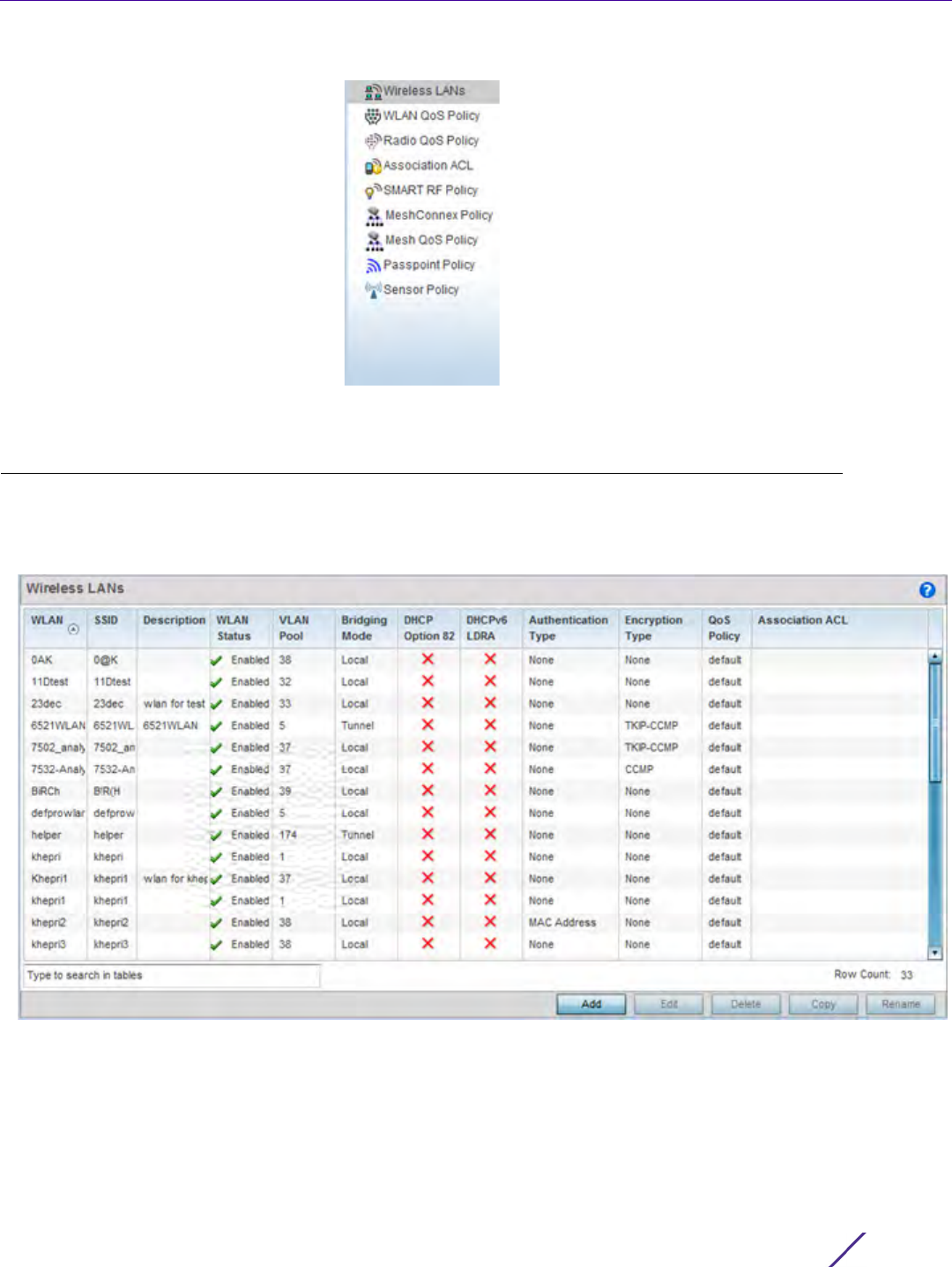
Wireless Configuration
Wireless Controller and Service Platform System Reference Guide 6 - 2
Figure 6-1 Configuration > Wireless pane
6.1 Wireless LAN Policy
To review the attributes of existing WLANs and, if necessary, modify their configurations:
1Select
Configuration > Wireless > Wireless LANs to display a high-level display of the existing WLANs.
Figure 6-2 Wireless LANs screen

Wireless Configuration
Wireless Controller and Service Platform System Reference Guide 6 - 3
2 Refer to the following (read only) information to assess the attributes of the each WLAN available to the
wireless controller:
WLAN Displays the name of each available WLAN. Individual WLANs can
selected and their SSID and client management properties modified.
RFS4000 and RFS6000 series wireless controllers support a maximum
of 32 WLANs. The NX7500 service platforms support up to 256
WLANs. NX9000 series service platforms support up to 1000 WLANs.
SSID Displays the name of the SSID assigned to the WLAN when created or
last modified. Optionally, select a WLAN and click the Edit button to
update the WLAN’s SSID.
Description Displays the brief description set for each listed WLAN when it was
either created or modified.
WLAN Status Lists each WLAN’s current status as either Active or Shutdown. A
green check mark defines the WLAN as available to clients on all
radios where it has been mapped. A red “X” defines the WLAN as
shutdown, meaning even if the WLAN is mapped to radios, it’s not
available for clients to associate.
VLAN Pool Lists each WLAN’s current VLAN mapping. The wireless controller
permits mapping a WLAN to more than one VLANs. When a client
associates with a WLAN, the client is assigned a VLAN by load balance
distribution. The VLAN is picked from a pool assigned to the WLAN.
Keep in mind however, typical deployments only map a single VLAN to
a WLAN. The use of a pool is strictly optional.
Bridging Mode Displays the bridging mode used by each WLAN. Available bridging
modes are Local and Tunnel.
DHCP Option 82 DHCP Option 82 is commonly used in large enterprise deployments to
provide client physical attachment information. Option 82 is used in
distributed DHCP server/relay environments, where relays insert
additional information to identify the client’s point of attachment. A
red “X” defines DHCP option 82 as disabled, a green check means its
enabled.
DHCPv6 LDRA Lightweight DHCPv6 Relay Agent (LDRA) is used to insert relay-agent
options in DHCPv6 message exchanges that identify client-facing
interfaces. These relay agents are deployed to forward DHCPv6
messages between clients and servers when they are not on the same
IPv6 link. A red “X” indicates this WLAN acts as a DHCPv6 LDRA.
Authentication Type Displays the name of the authentication scheme this WLAN is using to
secure its client membership transmissions. None is listed if
authentication is not used within this WLAN. Refer to the Encryption
type column if no authentication is used to verify there is some sort of
data protection used with the WLAN or risk no protection at all.
Encryption Type Displays the name of the encryption scheme this WLAN is using to
secure its client membership transmissions. None is listed if encryption
is not used within this WLAN. Refer to the Authentication type column
if no encryption is used to verify there is some sort of data protection
used with the WLAN or risk using this WLAN with no protection at all.
QoS Policy Lists the QoS policy applied to each listed WLAN. A QoS policy needs
to be custom selected (or created) for each WLAN in respect to the
WLAN’s intended client traffic and the voice, video or normal data
traffic it supports.

Wireless Configuration
Wireless Controller and Service Platform System Reference Guide 6 - 4
Use the sequential set of WLAN screens to define a unique configuration for each WLAN. Refer to the
following to set WLAN configurations:
•Basic WLAN Configuration
•Configuring WLAN Security
•Configuring WLAN Firewall Support
•Configuring Client Settings
•Configuring WLAN Accounting Settings
•Configuring WLAN Service Monitoring Settings
•Configuring Client Load Balancing Settings
•Configuring Advanced WLAN Settings
•Configuring Auto Shutdown Settings
6.1.1 Basic WLAN Configuration
Wireless LAN Policy
When creating or modifying a WLAN, the Basic Configuration screen is the first screen that displays as part of the
WLAN configuration screen flow. is the Use this screen to enable a WLAN and define its SSID, client behavior and
VLAN assignments.
1Select
Configuration > Wireless > Wireless LAN Policy to display a high-level display of the existing WLANs.
2 Select the Add button to create an additional WLAN, or select an existing WLAN then Edit to modify its
properties.
RFS4000 and RFS6000 model wireless controllers support a maximum of 32 WLANs. The NX7500 service
platform support up to 256 WLANs. The NX9000 Series supports up to 1000 WLANs.
Association ACL Lists the Association ACL policy applied to each listed WLAN. An
Association ACL is a policy-based Access Control List (ACL) that either
prevents or allows wireless clients from connecting to a WLAN. The
mapping of an Association ACL is strictly optional.
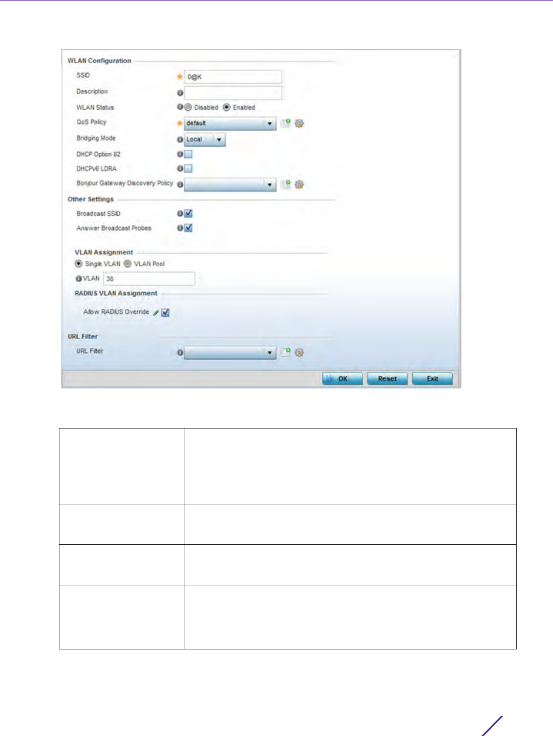
Wireless Configuration
Wireless Controller and Service Platform System Reference Guide 6 - 5
Figure 6-3 WLAN Policy Basic Configuration screen
3 Refer to the WLAN Configuration field to define the following:
WLAN If adding a new WLAN, enter its name in the space provided. Spaces
between words are not permitted. The name could be a logical
representation of the WLAN coverage area (engineering, marketing
etc.). If editing an existing WLAN, the WLAN’s name appears at the
top of the screen and cannot be modified. The name cannot exceed 32
characters.
SSID Enter or modify the Services Set Identification (SSID) associated with
the WLAN. The maximum number of characters that can be used for
the SSID is 32.
Description Provide a textual description for the WLAN to help differentiate it from
others with similar configurations. The description can be up to 64
characters.
WLAN Status Select the Enabled radio button to make this WLAN active and
available to clients on all radios where it has been mapped. Select the
Disabled radio button to make this WLAN inactive, meaning even if the
WLAN is mapped to radios, it’s not available for clients to associate
and use.

Wireless Configuration
Wireless Controller and Service Platform System Reference Guide 6 - 6
4 Refer to the Other Settings field to define broadcast behavior within this specific WLAN.
5 Refer to the VLAN Assignment field to add or remove VLANs for the selected WLAN, and define the number of
clients permitted. Remember, users belonging to separate VLANs can share the same WLAN. It’s not necessary
to create a new WLAN for every VLAN in the network.
6 Select the Allow Radius Override check box in the RADIUS VLAN Assignment to allow an override to the WLAN
configuration. If, as part of the authentication process, the RADIUS server returns a client’s VLAN-ID in a
QoS Policy Use the drop-down menu to assign an existing QoS policy to the
WLAN or select the Create icon to define a new QoS policy or select
the Edit icon to modify the configuration of the selected QoS Policy.
QoS helps ensure each WLAN receives a fair share of the overall
bandwidth, either equally or per the proportion configured. For
information on creating a QoS policy that can be applied to WLAN,
see Configuring WLAN QoS Policies.
Bridging Mode Use the drop-down menu to specify a bridging mode for the WLAN.
Available bridging policy modes are Local, Tunnel or
split-tunnel.
DHCP Option 82 Select this option to enable DHCP option 82. DHCP Option 82 provides
client physical attachment information. This setting is disabled by
default.
DHCPv6 LDRA Select this option to enable the DHCPv6 relay agent. The DHCPv6
LDRA (Lightweight DHCP Relay Agent) allows for DHCPv6 messages
to be transmitted on existing networks that do not currently support
IPv6 or DHCPv6.
Bonjour Gateway
Discovery Policy
Select an existing Bonjour configuration to apply to the WLAN
configuration. Bonjour provides a method to discover services on a
WLAN. Bonjour allows users to set up a network without any
configuration. Services such as printers, scanners and file-sharing
servers can be found using Bonjour. Bonjour only works within a single
broadcast domain. However, with a special DNS configuration, it can
be extended to find services across broadcast domains.
Broadcast SSID Select this check box to enable the wireless controller to broadcast
SSIDs within beacons. If a hacker tries to isolate and hack a client SSID
via a client, the ESSID will display since the ESSID is in the beacon.
This feature is enabled by default.
Answer Broadcast
Probes
Select this check box to associate a client with a blank SSID
(regardless of which SSID the wireless controller is currently using).
This feature is enabled by default.
Single VLAN Select the Single VLAN radio button to assign just one VLAN to this
WLAN. Enter the name of the VLAN within the VLAN parameter field
when the Single VLAN radio button is selected. Utilizing a single VLAN
per WLAN is a more typical deployment scenario than using a VLAN
pool.
VLAN Pool Select the VLAN Pool radio button to display a table with VLAN and
wireless client columns (representing configurable options). Define the
VLANs available to this WLAN. Additionally, define the number of
wireless clients supported by each VLAN. Use the radio button’s on
the left-hand side of the table to enable or disable each VLAN and
wireless client configuration for the WLAN. Select the + Add Row
button to add additional VLANs to the WLAN.

Wireless Configuration
Wireless Controller and Service Platform System Reference Guide 6 - 7
RADIUS Access-Accept packet, and this feature is enabled, all client traffic is forward on that VLAN. If disabled,
the RADIUS server returned VLAN-ID is ignored and the VLAN configuration (defined above) is used.
7Use the URL Filter field to configure user access restrictions to resources on the controller or service platform
managed Internet. User access is controlled with URL Filters. Use the URL Filter drop down menu to select a
preconfigured URL Filter. To create a new URL Filter, use the Create button. To edit an existing URL Filter, use
the Edit button.
8Select
OK when completed to update the WLAN’s basic configuration. Select Reset to revert the screen back to
the last saved configuration.
6.1.2 Configuring WLAN Security
Wireless LAN Policy
A WLAN can be assigned a security policy supporting authentication, captive portal (hotspot) or encryption
schemes.
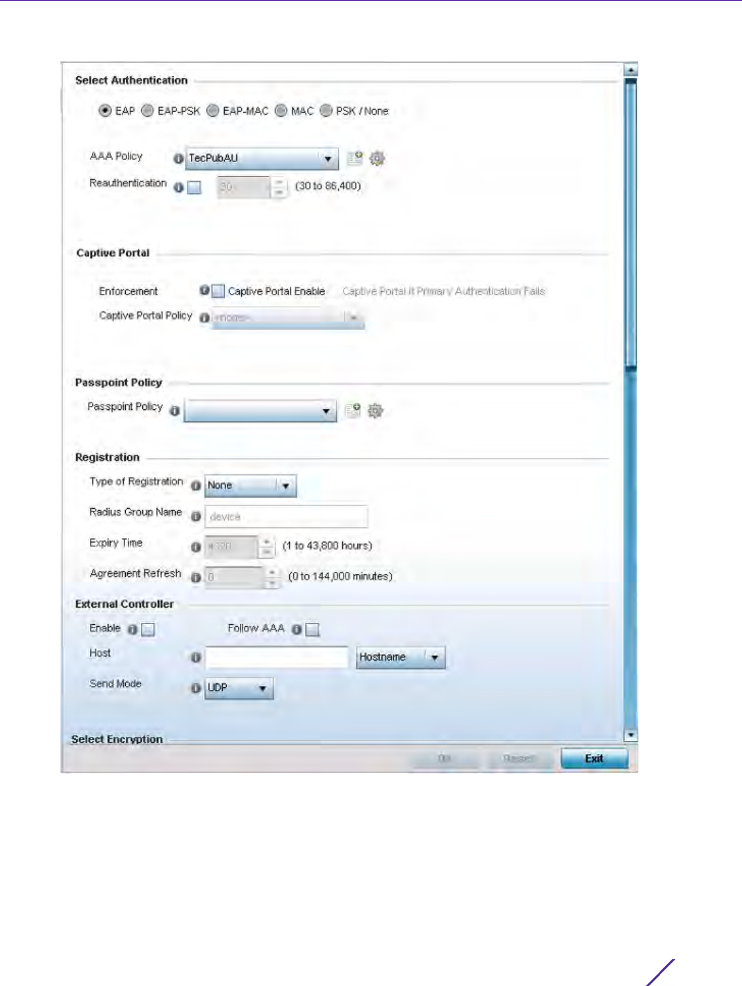
Wireless Configuration
Wireless Controller and Service Platform System Reference Guide 6 - 8
Figure 6-4 WLAN Policy Security screen
Authentication ensures only known and trusted users or devices access a WLAN. Authentication is enabled per
WLAN to verify the identity of both users and devices. Authentication is a challenge and response procedure for
validating user credentials such as username, password and sometimes secret-key information.
A client must authenticate to an Access Point to receive resources from the network. Controllers and service
platforms support EAP, EAP PSK, EAP-MAC, MAC and PSK/None authentication options.
Refer to the following to configure an authentication scheme for a WLAN:

Wireless Configuration
Wireless Controller and Service Platform System Reference Guide 6 - 9
•802.1x EAP, EAP-PSK and EAP MAC
•MAC Authentication
•PSK / None
Secure guest access to the network is referred to as captive portal access. A captive portal is guest access policy
for providing guests temporary and restrictive access to the wireless network. Existing captive portal policies can
be applied to a WLAN to provide secure guest access as needed.
A captive portal configuration provides secure authenticated access using a standard Web browser. Captive portals
provide authenticated access by capturing and re-directing a wireless user's Web browser session to a captive
portal login page where the user must enter valid credentials to access to the network. Once logged into captive
portal, additional Agreement, Welcome and Fail pages provide the administrator with a number of options on
captive portal screen flow and user appearance. Refer to Captive Portal on page 6-13 for information on assigning
a captive portal policy to a WLAN.
A passpoint policy provides an interoperable platform for streamlining Wi-Fi access to Access Points deployed as
public hotspots. Passpoint is supported across a wide range of wireless network deployment scenarios and client
devices. For more information, see Passpoint Policy.
Encryption is central for WLAN security, as it provides data privacy for traffic forwarded over a WLAN. When the
802.11 specification was introduced, Wired Equivalent Privacy (WEP) was the primary encryption mechanism. WEP
has since been interpreted as flawed in many ways, and is not considered an effective standalone encryption
scheme for securing a wireless controller WLAN. WEP is typically used WLAN deployments designed to support
legacy clients. New device deployments should use either WPA or WPA2 encryption.
Encryption applies a specific algorithm to alter its appearance and prevent unauthorized hacking. Decryption
applies the algorithm in reverse, to restore the data to its original form. A sender and receiver must employ the
same encryption/decryption method to interoperate. When both TKIP and CCMP are both enabled a mix of clients
are allowed to associate with the WLAN. Some use TKIP, others use CCMP. Since broadcast traffic needs to be
understood by all clients, the broadcast encryption type in this scenario is TKIP.
TKIP-CCMP, WPA2-CCMP, WEP 64, WEP 128 and Keyguard encryption options are supported.
Refer to the following to configure an encryption scheme for a WLAN:
•TKIP-CCMP
•WPA2-CCMP
•WEP 64
•WEP 128
•Keyguard
•T5 Controller Security
6.1.2.1 802.1x EAP, EAP-PSK and EAP MAC
Configuring WLAN Security
The Extensible Authentication Protocol (EAP) is the de-facto standard authentication method used to provide
secure authenticated access to WLANs. EAP provides mutual authentication, secured credential exchange,
dynamic keying and strong encryption. 802.1X EAP can be deployed with WEP, WPA or WPA2 encryption schemes
to further protect user information forwarded over WLANs.
The EAP process begins when an unauthenticated supplicant (client device) tries to connect with an authenticator
(in this case, the authentication server). An Access Point passes EAP packets from the client to an authentication

Wireless Configuration
Wireless Controller and Service Platform System Reference Guide 6 - 10
server on the wired side of the Access Point. All other packet types are blocked until the authentication server
(typically, a RADIUS server) verifies the client’s identity.
802.1X EAP provides mutual authentication over the WLAN during authentication. The 802.1X EAP process uses
credential verification to apply specific policies and restrictions to WLAN users to ensure access is only provided to
specific wireless controller resources.
802.1X requires a 802.1X capable RADIUS server to authenticate users and a 802.1X client installed on each devices
accessing the EAP supported WLAN. An 802.1X client is included with most commercial operating systems,
including Microsoft Windows, Linux and Apple OS X.
The RADIUS server authenticating 802.1X EAP users can reside either internally or externally to a controller, service
platform or Access Point. User account creation and maintenance can be provided centrally using ADSP or
individually maintained on each device. If an external RADIUS server is used, EAP authentication requests are
forwarded.
When using PSK with EAP, the controller, service platform or Access Point sends a packet requesting a secure link
using a pre-shared key. The authenticating device must use the same authenticating algorithm and passcode
during authentication. EAP-PSK is useful when transitioning from a PSK network to one that supports EAP. The
only encryption types supported with this are TKIP, CCMP and TKIP-CCMP.
To configure EAP on a WLAN:
1Select
Configuration > Wireless > Wireless LAN Policy to display available WLANs.
2 Select the Add button to create an additional WLAN, or select and existing WLAN and Edit to modify the
security properties of an existing WLAN.
3Select
Security.
4Select
EAP, EAP-PSK or EAP-MAC as the authentication type.
Either option enables the radio buttons for various encryption mechanisms as an additional measure of security
with the WLAN.
Figure 6-5 EAP, EAP-PSK or EAP MAC Authentication screen
5 Either select an existing AAA Policy from the drop-down menu or select the Create icon to the right of the
AAA Policy parameter to display a screen where new AAA policies can be created. Select the Edit icon to
modify the configuration of the selected AAA policy.
Authentication, authorization, and accounting (AAA) is a framework for intelligently controlling access to the
network, enforcing user authorization policies and auditing and tracking usage. These combined processes are
central for securing wireless client resources and wireless network data flows.
6Select the
Reauthentication check box to force EAP supported clients to reauthenticate. Use the spinner control
set the number of seconds (from 30 - 86,400) that, once exceeded, forces the EAP supported client to
reauthenticate to use the resources supported by the WLAN.

Wireless Configuration
Wireless Controller and Service Platform System Reference Guide 6 - 11
7Select OK when completed to update the WLAN’s EAP configuration. Select Reset to revert back to the last
saved configuration.
EAP, EAP-PSK and EAP MAC Deployment Considerations
802.1x EAP, EAP-PSK and EAP MAC
Before defining a 802.1x EAP, EAP-PSK or EAP MAC supported configuration on a WLAN, refer to the following
deployment guidelines to ensure the configuration is optimally effective:
• A valid certificate should be issued and installed on devices providing 802.1X EAP. The certificate should be
issued from an Enterprise or public certificate authority to allow 802.1X clients to validate the identity of the
authentication server prior to forwarding credentials.
• If using an external RADIUS server for EAP authentication, the round trip delay over the WAN should not
exceed 150ms. Excessive delays over a WAN can cause authentication and roaming issues and impact wireless
client performance. If experiencing excessive delays, consider using local RADIUS resources.
6.1.2.2 MAC Authentication
Configuring WLAN Security
MAC is a device level authentication method used to augment other security schemes when legacy devices are
deployed using static WEP.
MAC authentication can be used for device level authentication by permitting WLAN access based on device MAC
address. MAC authentication is typically used to augment WLAN security options that do not use authentication
(such as static WEP, WPA-PSK and WPA2-PSK) MAC authentication can also be used to assign VLAN
memberships, Firewall policies and time and date restrictions.
MAC authentication can only identify devices, not users. MAC authentication only references a client wireless
interface card MAC address when authenticating the device, it does not distinguish the device’s user credentials.
MAC authentication is somewhat poor as a standalone data protection technique, as MAC addresses can be easily
spoofed by hackers who can provide a device MAC address to mimic a trusted device within the network.
MAC authentication is enabled per WLAN profile, augmented with the use of a RADIUS server to authenticate
each device. A device’s MAC address can be authenticated against the local RADIUS server built into the device or
centrally (from a datacenter). For RADIUS server compatibility, the format of the MAC address can be forwarded
to the RADIUS server in non-delimited and or delimited formats:
To configure MAC on a WLAN:
1Select
Configuration > Wireless > Wireless LAN Policy to display available WLANs.
2 Select the Add button to create an additional WLAN, or select and existing WLAN and Edit to modify the
security properties of an existing WLAN.
3Select
Security.
4Select
MAC as the Authentication Type.
Selecting MAC enables the radio buttons for each encryption option as an additional measure of security for
the WLAN.

Wireless Configuration
Wireless Controller and Service Platform System Reference Guide 6 - 12
Figure 6-6 MAC Authentication screen
5 Either select an existing AAA Policy from the drop-down menu or select the Create icon to the right of the AAA
Policy parameter to display a screen where new AAA policies can be created. A default AAA policy is also
available if configuring a WLAN for the first time and there’s no existing policies. Select the Edit icon to modify
the configuration of a selected AAA policy.
Authentication, authorization, and accounting (AAA) is a framework for intelligently controlling access to the
wireless client, enforcing user authorization policies and auditing and tracking usage. These combined
processes are central for securing wireless client resources and wireless network data flows.
6 Select the Reauthentication option to force MAC supported clients to reauthenticate. Use the spinner control
set the number of minutes (30 - 86,400) that, once exceeded, forces the EAP supported client to
reauthenticate in order to use the resources supported by the WLAN.
7Select
OK when completed to update the WLAN’s MAC configuration. Select Reset to revert the screen back to
the last saved configuration.
MAC Authentication Deployment Considerations
MAC Authentication
Before defining a MAC authentication configuration on a WLAN, refer to the following deployment guidelines to
ensure the configuration is optimally effective:
• MAC authentication can only be used to identify end-user devices, not the users themselves.
• MAC authentication is somewhat poor as a standalone data protection technique, as MAC addresses can be
easily spoofed by hackers who can provision a MAC address on their device to mimic a trusted device.
6.1.2.3 PSK / None
Configuring WLAN Security
Open-system authentication can be referred to as no authentication, since no actual authentication and user
credential validation takes place. A client user requests (and is granted) authentication with no credential
exchange.
Wireless Configuration
Wireless Controller and Service Platform System Reference Guide 6 - 13
Figure 6-7 PSK / None Settings screen
6.1.2.4 Captive Portal
Configuring WLAN Security
A captive portal is an access policy for providing guests temporary and restrictive access to the controller, service
platform or Access Point managed network. For an overview of the Captive Portal process and information on how
to define a captive portal policy, see Configuring Captive Portal Policies on page 11-1.
To assign a captive portal policy to a WLAN:
1Select
Configuration > Wireless > Wireless LAN Policy to display available WLANs.
2 Select the Add button to create an additional WLAN or select an existing WLAN and select Edit to modify the
properties of an existing wireless controller WLAN.
3Select
Security.
4 Refer to the Captive Portal field within the WLAN Policy security screen.
Figure 6-8 WLAN Policy Security screen - Captive Portal Field
5 Select the Captive Portal Enable option if authenticated guest access is required with the selected WLAN. This
feature is disabled by default.
6 Select the Captive Portal if Primary Authentication Fails checkbox to enable the captive portal policy if the
primary authentication is unavailable. This option is only enabled when Captive Portal Enable is selected.
7 Select the Captive Portal Policy to use with the WLAN from the drop-down menu. If no relevant policies exist,
select the Create icon to define a new policy to use with this WLAN or the Edit icon to update the configuration
of an existing Captive Portal policy. For more information, see Configuring Captive Portal Policies on page 11-1.
8Select
OK when completed to update the Captive Portal configuration. Select Reset to revert the WLAN Policy
Security screen back to the last saved configuration.
NOTE: Although None implies no authentication, this option is also used when pre-
shared keys are used for encryption (thus the PSK in the description).
Wireless Configuration
Wireless Controller and Service Platform System Reference Guide 6 - 14
6.1.2.5 Passpoint
Configuring WLAN Security
A passpoint policy provides an interoperable platform for streamlining Wi-Fi access to Access Points deployed as
public hotspots (captive portals). Passpoint is supported across a wide range of wireless network deployment
scenarios and client devices.
To assign a passpoint policy to a WLAN:
1Select
Configuration > Wireless > Wireless LAN Policy to display available WLANs.
2 Select the Add button to create an additional WLAN or select an existing WLAN and select Edit to modify the
properties of an existing wireless controller WLAN.
3Select
Security.
4 Refer to the Passpoint field within the WLAN Policy security screen.
Figure 6-9 WLAN Policy Security screen - Passpoint Policy
5 Select an existing Passpoint Policy from the drop down menu to apply it to the WLAN. If no relevant policies
exist, select the Create icon to define a new policy to use with this WLAN or the Edit icon to update the
configuration of an existing passpoint policy. For more information, see Passpoint Policy on page 6-104.
6Select
OK when completed to update the Captive Portal configuration. Select Reset to revert the WLAN Policy
Security screen back to the last saved configuration.
6.1.2.6 Registration
Configuring WLAN Security
Registration requires the validation of devices by address to continue the authentication process.
To assign a Registration to a WLAN:
1Select
Configuration > Wireless > Wireless LAN Policy to display available WLANs.
2 Select the Add button to create an additional WLAN or select an existing WLAN and select Edit to modify the
properties of an existing wireless controller WLAN.
3Select
Security.
4 Refer to the Registration section within the WLAN Policy security screen.
Figure 6-10 WLAN Policy Security screen - MAC Registration
Wireless Configuration
Wireless Controller and Service Platform System Reference Guide 6 - 15
5Use the Type of Registration drop-down menu to set the self-registration type for the selected WLAN. Options
include None, device, user and device-OTP.
When captive portal guest users are authenticating using their User ID (Email Address/Mobile Number/
Member ID) and the received pass code in order to complete the registration process. The WLAN
authentication type should be MAC-Authentication and the WLAN registration type should be configured as
device-OTP.
When captive portal device registration is through social media, the WLAN registration type should be set as
device registration, and the captive portal needs to be configured for guest user social authentication.
Enter a 64 character maximum RADIUS Group Name to which the registering user associates. When left blank,
users are not associated with a RADIUS group.
Use the Expiry Time spinner control to set the amount of time (from 1 - 43,800 hours) before registration
addresses expire and must be re-entered.
Set the Agreement Refresh as the amount of time (from 0 - 144,000 minutes) before the agreement page is
displayed if the user has not been logged during the specified period. The default setting is 0 days.
6Select
OK when completed to update the Registration settings. Select Reset to revert the WLAN Policy Security
screen back to the last saved configuration.
6.1.2.7 External Controller
Configuring WLAN Security
To set the WLAN’s external controller or service platform security configuration:
1Select
Configuration > Wireless > Wireless LAN Policy to display available WLANs.
2 Select the Add button to create an additional WLAN or select an existing WLAN and select Edit to modify its
properties.
3Select
Security.
4 Refer to the External Controller section within the WLAN Policy security screen
Figure 6-11 WLAN Policy Security screen - External Controller Field
5 Select the Enable option if WLAN authentication is handled using an external resource. This feature is disabled
by default.
Select the Follow AAA option if the resource handling WLAN authentication and accounting is an external
RADIUS server specified within an AAA policy. However, ensure that an AAA policy identifying the
authentication and accounting server exists and is associated with the WLAN.
Note, in case of EGuest deployment, the authenticating and accounting server specified in the AAA policy
should point to the EGuest server host.
6 If using an external resource, other than the AAA RADIUS server, use the drop-down menu to select either
Hostname or IP Address and enter the server information in the Host field. Hostnames cannot include an
underscore character.
Wireless Configuration
Wireless Controller and Service Platform System Reference Guide 6 - 16
7 Select the Send Mode as either UDP, HTTP or HTTPS. The default setting is UDP.
8Select
OK when completed to update the External Controller configuration. Select Reset to revert the WLAN
Policy Security screen back to the last saved configuration.
6.1.2.8 TKIP-CCMP
Configuring WLAN Security
CCMP is a security standard used by the Advanced Encryption Standard (AES). AES serves the same function TKIP
does for WPA-TKIP. CCMP computes a Message Integrity Check (MIC) using the proven Cipher Block Chaining
(CBC) technique. Changing just one bit in a message produces a totally different result.
The encryption method is Temporal Key Integrity Protocol (TKIP). TKIP addresses WEP’s weaknesses with a re-
keying mechanism, a per-packet mixing function, a message integrity check and an extended initialization vector.
However TKIP also has vulnerabilities.
To configure TKIP-CCMP encryption on a WLAN:
1Select
Configuration > Wireless > Wireless LAN Policy to display available WLANs.
2 Select the Add button to create an additional WLAN or select an existing WLAN and Edit to modify its
properties.
3Select
Security.
4 Select the TKIP-CCMP radio button from within the Select Encryption field.
The screen populates with the parameters required to define a WLAN’s TKIP-CCMP configuration for the new
or existing WLAN.
Figure 6-12 TKIP-CCMP screen

Wireless Configuration
Wireless Controller and Service Platform System Reference Guide 6 - 17
5Define Key Settings.
6Define
Key Rotation values.
Unicast messages are addressed to a single device on the network. Broadcast messages are addressed to
multiple devices. When using WPA2, a wireless client can use 2 keys, one unicast key, for its own traffic to and
from an Access Point, and one broadcast key, the common key for all the clients in that subnet.
Rotating the keys is recommended the keys so a potential hacker would not have enough data using a single
key to attack the deployed encryption scheme.
7 Set the following Advanced settings for the WPA/WPA2-TKIP encryption scheme
8Select
OK when completed to update the WLAN’s TKIP-CCMP encryption configuration. Select Reset to revert
the screen back to its last saved configuration.
6.1.2.8.1 TKIP-CCMP Deployment Considerations
Before defining a TKIP-CCMP supported configuration on a WLAN, refer to the following deployment guidelines to
ensure the configuration is optimally effective:
• TKIP-CCMP should only be enabled for legacy device support when WPA2-CCMP support is not available.
• Though TKIP offers better security than WEP, it can be vulnerable to certain attacks.
Pre-Shared Key Enter either an alphanumeric string of 8 to 63 ASCII characters or 64
HEX characters as the primary string both transmitting and receiving
authenticators must share. The alphanumeric string allows character
spaces. The string is converted into a numeric value. This passphrase
saves the administrator from entering the 256-bit key each time keys are
generated.
Unicast Rotation
Interval
Define an interval for unicast key transmission in seconds (30 -86,400).
Some clients have issues using unicast key rotation, so ensure you know
which kind of clients are impacted before using unicast keys. This feature
is disabled by default.
Broadcast Rotation
Interval
When enabled, the key indices used for encrypting/decrypting broadcast
traffic are alternatively rotated based on the defined interval. Define an
interval for broadcast key transmission in seconds (30-86,400). Key
rotation enhances the broadcast traffic security on the WLAN. This
feature is disabled by default.
TKIP Countermeasure
Hold Time
The TKIP countermeasure hold-time is the time during which the use of
the WLAN is disabled if TKIP countermeasures have been invoked on the
WLAN. Use the drop-down menu to define a value in either Hours (0-18),
Minutes (0-1,093) or Seconds (0-65,535). The default setting is 1 second.
Exclude WPA2 TKIP Select this option for an Access Point to advertise and enable support
for only WPA-TKIP. This option can be used if certain older clients are
not compatible with the newer WPA2-TKIP information elements.
Enabling this option allows backwards compatibility for clients that
support WPA-TKIP and WPA2-TKIP but do not support WPA2-CCMP.
Enabling this feature is recommended if WPA-TKIP or WPA2-TKIP
supported clients operate in a WLAN populated by WPA2-CCMP
enabled clients. This feature is disabled by default.
Use SHA256 Select to enable use of the SHA-256 hash algorithms with WPA2. This is
optional when using WPA2 without 802.11w Protected Management
Frames (PMF) enabled. This is mandatory when PMF is enabled.

Wireless Configuration
Wireless Controller and Service Platform System Reference Guide 6 - 18
• When both TKIP and CCMP are both enabled a mix of clients are allowed to associate with the WLAN. Some
use TKIP, others use CCMP. Since broadcast traffic needs to be understood by all clients, the broadcast
encryption type in this scenario is TKIP.
6.1.2.9 WPA2-CCMP
Configuring WLAN Security
WPA2 is a newer 802.11i standard that provides even stronger wireless security than Wi-Fi Protected Access (WPA)
and WEP. CCMP is the security standard used by the Advanced Encryption Standard (AES). AES serves the same
function TKIP does for WPA-TKIP. CCMP computes a Message Integrity Check (MIC) using the proven Cipher Block
Chaining (CBC) technique. Changing just one bit in a message produces a totally different result.
WPA2/CCMP is based on the concept of a Robust Security Network (RSN), which defines a hierarchy of keys with
a limited lifetime (similar to TKIP). Like TKIP, the keys the administrator provides are used to derive other keys.
Messages are encrypted using a 128-bit secret key and a 128-bit block of data. The end result is an encryption
scheme as secure as any the wireless controller provides for its associated clients.
To configure WPA2-CCMP encryption on a WLAN:
1Select
Configuration > Wireless > Wireless LAN Policy to display available WLANs.
2 Select the Add button to create an additional WLAN or select an existing WLAN and choose Edit to modify the
properties of an existing WLAN.
3Select
Security.
4 Select the WPA2-CCMP check box from within the select Select Encryption field.
The screen populates with the parameters required to define a WPA2-CCMP configuration for the new or
existing WLAN.
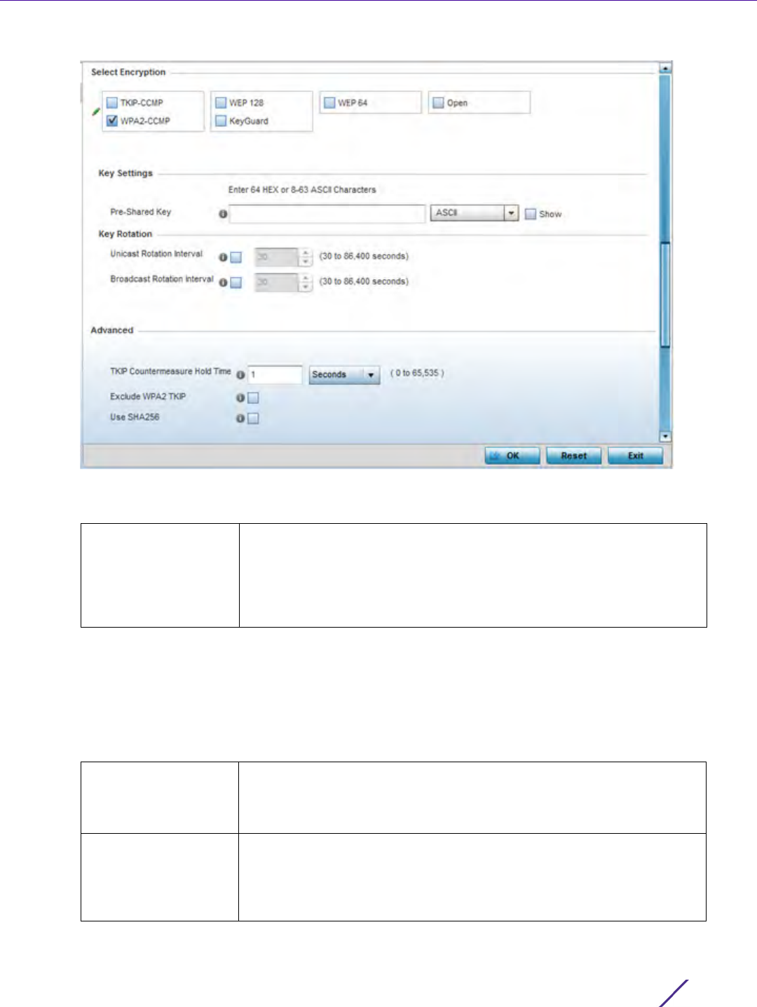
Wireless Configuration
Wireless Controller and Service Platform System Reference Guide 6 - 19
Figure 6-13 WPA2-CCMP screen
5Define Key Settings.
6Define
Key Rotation values.
Unicast messages are addressed to a single device on the network. Broadcast messages are addressed to
multiple devices. When using WPA2-CCMP, a wireless client can use 2 keys: one unicast key, for its own traffic
to and from an Access Point, and one broadcast key, the common key for all the clients in that subnet.
Rotating these keys is recommended so a potential hacker will not have enough data using a single key to
attack the deployed encryption scheme.
Pre-Shared Key Enter either an alphanumeric string of 8 to 63 ASCII characters or 64
HEX characters as the primary string both transmitting and receiving
authenticators must share. The alphanumeric string allows character
spaces. The string is converted to a numeric value. This passphrase saves
the administrator from entering the 256-bit key each time keys are
generated.
Unicast Rotation
Interval
Define an interval for unicast key transmission in seconds (30 -86,400).
Some clients have issues using unicast key rotation, so ensure you know
which clients are impacted before using unicast keys. This value is
disabled by default.
Broadcast Rotation
Interval
When enabled, the key indices used for encrypting/decrypting
broadcast traffic are alternatively rotated based on the defined interval.
Define an interval for broadcast key transmission in seconds (30-
86,400). Key rotation enhances the broadcast traffic security on the
WLAN. This value is disabled by default.

Wireless Configuration
Wireless Controller and Service Platform System Reference Guide 6 - 20
7 Set the following Advanced for the WPA2-CCMP encryption scheme.
8Select
OK when completed to update the WLAN’s WPA2-CCMP encryption configuration. Select Reset to revert
back to its last saved configuration.
WPA2-CCMP Deployment Considerations
WPA2-CCMP
Before defining a WPA2-CCMP supported configuration on a wireless controller WLAN, refer to the following
deployment guidelines to ensure the configuration is optimally effective:
• WPA2-CCMP should be configured for all new (non visitor) WLANs requiring encryption, as it’s supported by
the majority of the hardware and client vendors using wireless networking equipment.
• WPA2-CCMP supersedes WPA-TKIP and implements all the mandatory elements of the 802.11i standard. WPA2-
CCMP introduces a new AES-based algorithm called CCMP which replaces TKIP and WEP and is considered
significantly more secure.
6.1.2.10 WEP 64
Configuring WLAN Security
Wired Equivalent Privacy (WEP) is a security protocol specified in the IEEE Wireless Fidelity (Wi -Fi) standard.
WEP is designed to provide a WLAN with a level of security and privacy comparable to that of a wired LAN.
WEP can be used with open, shared, MAC and 802.1 X EAP authentications. WEP is optimal for WLANs supporting
legacy deployments when also used with 802.1X EAP authentication to provide user and device authentication and
dynamic WEP key derivation and periodic key rotation. 802.1X provides authentication for devices and also reduces
the risk of a single WEP key being deciphered. If 802.1X support is not available on the legacy device, MAC
authentication should be enabled to provide device level authentication.
WEP 64 uses a 40 bit key concatenated with a 24-bit initialization vector (IV) to form the RC4 traffic key. WEP 64
is a less robust encryption scheme than WEP 128 (containing a shorter WEP algorithm for a hacker to potentially
duplicate), but networks that require more security are at risk from a WEP flaw. WEP is only recommended if there
TKIP Countermeasure
Hold Time
The TKIP countermeasure hold-time is the time during which the use
of the WLAN is disabled if TKIP countermeasures have been invoked
on the WLAN. Use the drop-down menu to define a value in either
Hours (0-18), Minutes (0-1,092) or Seconds (0-65,535). The default
setting is 60 seconds.
Exclude WPA2-TKIP Select this option for an Access Point to advertise and enable support
for only WPA-TKIP. Select this option if certain older clients are not
compatible with the newer WPA2-TKIP information elements. Enabling
this option allows backwards compatibility for clients that support
WPA-TKIP and WPA2-TKIP but do not support WPA2-CCMP. Consider
enabling this feature if WPA-TKIP or WPA2-TKIP supported clients
operate in a WLAN populated by WPA2-CCMP enabled clients. This
feature is disabled by default.
Use SHA256 Select this option for an Access Point to advertise and enable support
for only WPA-TKIP. Select this option if certain older clients are not
compatible with the newer WPA2-TKIP information elements. Enabling
this option allows backwards compatibility for clients that support
WPA-TKIP and WPA2-TKIP but do not support WPA2-CCMP. Consider
enabling this feature if WPA-TKIP or WPA2-TKIP supported clients
operate in a WLAN populated by WPA2-CCMP enabled clients. This
feature is disabled by default.
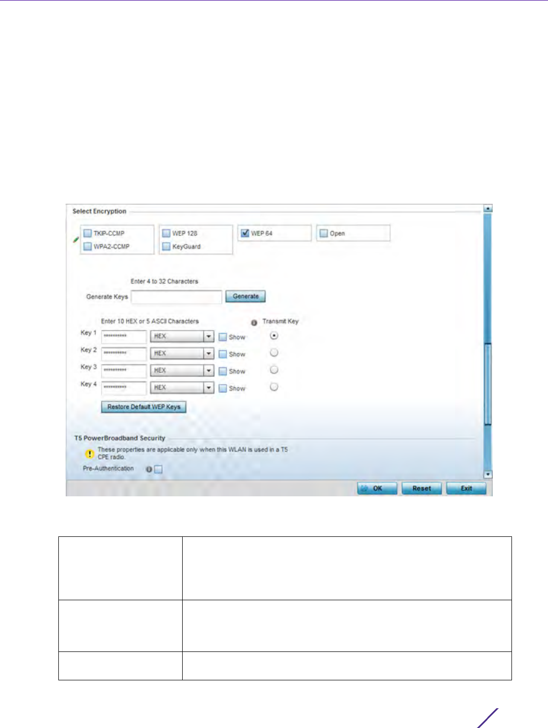
Wireless Configuration
Wireless Controller and Service Platform System Reference Guide 6 - 21
are client devices incapable of using higher forms of security. The existing 802.11 standard alone offers
administrators no effective method to update keys.
To configure WEP 64 encryption on a WLAN:
1Select
Configuration > Wireless > Wireless LAN Policy to display available WLANs.
2 Select the Add button to create an additional WLAN or select Edit to modify the properties of an existing
WLAN.
3Select
Security.
4 Select the WEP 64 check box from within the Select Encryption field.
The screen populates with the parameters required to define a WEP 64 configuration for the WLAN.
Figure 6-14 WEP 64 screen
5 Configure the following WEP 64 settings:
Generate Keys Specify a 4 to 32 character Pass Key and click the Generate button.
The pass key can be any alphanumeric string. Wireless devices and
their connected clients use the algorithm to convert an ASCII string to
the same hexadecimal number. Clients without adapters need to use
WEP keys manually configured as hexadecimal numbers.
Keys 1-4 Use the Key #1-4 fields to specify key numbers. For WEP 64 (40-bit
key), the keys are 10 hexadecimal characters in length. Select one of
these keys for default activation by clicking its radio button. Selecting
Show displays a key in exposed plain text.
Restore Default WEP
Keys
If you feel it necessary to restore the WEP algorithm back to its default
settings, click the Restore Default WEP Keys button.

Wireless Configuration
Wireless Controller and Service Platform System Reference Guide 6 - 22
Default WEP 64 keys are as follows:
• Key 1 1011121314
• Key 2 2021222324
• Key 3 3031323334
• Key 4 4041424344
6Select
OK when completed to update the WLAN’s WEP 64 encryption configuration. Select Reset to revert the
screen back to its last saved configuration.
WEP 64 Deployment Considerations
Before defining a WEP 64 supported configuration on a wireless controller WLAN, refer to the following
deployment guidelines to ensure the configuration is optimally effective:
• Additional layers of security (beyond WEP) should be enabled to minimize the likelihood of data loss and
security breaches. WEP enabled WLANs should be mapped to an isolated VLAN with firewall policies restricting
access to hosts and suspicious network applications.
• WEP enabled WLANs should only be permitted access to resources required by legacy devices.
• If WEP support is needed for WLAN legacy device support, 802.1X EAP authentication should be also
configured in order for the WLAN to provide authentication and dynamic key derivation and rotation.
6.1.2.11 WEP 128
Configuring WLAN Security
Wired Equivalent Privacy (WEP) is a security protocol specified in the IEEE Wireless Fidelity (Wi -Fi) standard.
WEP is designed to provide a WLAN with a level of security and privacy comparable to that of a wired LAN.
WEP can be used with open, shared, MAC and 802.1 X EAP authentications. WEP is optimal for WLANs supporting
legacy deployments when also used with 802.1X EAP authentication to provide user and device authentication and
dynamic WEP key derivation and periodic key rotation. 802.1X provides authentication for devices and also reduces
the risk of a single WEP key being deciphered. If 802.1X support is not available on the legacy device, MAC
authentication should be enabled to provide device level authentication.
WEP 128 uses a 104 bit key which is concatenated with a 24-bit initialization vector (IV) to form the RC4 traffic
key. WEP may be all a small-business user needs for the simple encryption of wireless data. However, networks
that require more security are at risk from a WEP flaw. WEP is only recommended if there are client devices
incapable of using higher forms of security. The existing 802.11 standard alone offers administrators no effective
method to update keys.
WEP 128 provides a more robust encryption algorithm than WEP 64 by requiring a longer key length and pass key.
Thus, making it harder to hack through the replication of WEP keys.
To configure WEP 128 encryption on a WLAN:
1Select
Configuration > Wireless > Wireless LAN Policy to display available WLANs.
2 Select the Add button to create an additional WLAN or select Edit to modify the properties of an existing
WLAN.
3Select
Security.
4 Select the WEP 128 check box from within the Select Encryption field.
The screen populates with the parameters required to define a WEP 128 configuration for the WLAN.
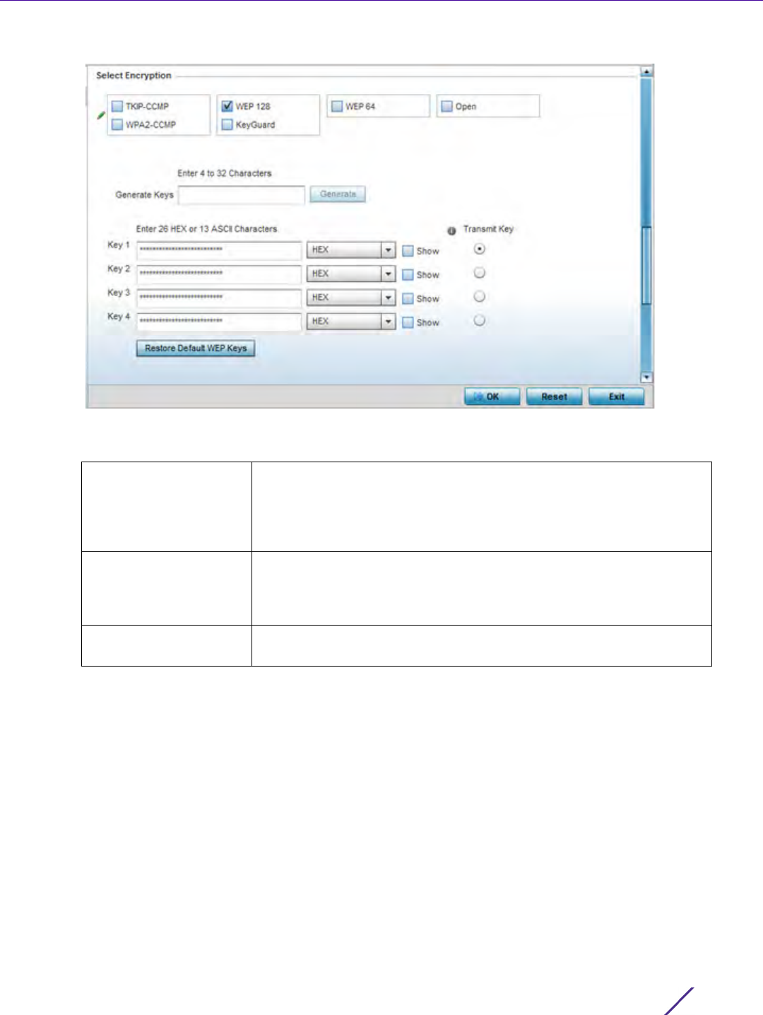
Wireless Configuration
Wireless Controller and Service Platform System Reference Guide 6 - 23
Figure 6-15 WEP 128 screen
5 Configure the following WEP 128 settings:
Default WEP 128 keys are as follows:
• Key 1 101112131415161718191A1B1C
• Key 2 202122232425262728292A2B2C
• Key 3 303132333435363738393A3B3C
• Key 4 404142434445464748494A4B4C
6Select
OK when completed to update the WLAN’s WEP 128 encryption configuration. Select Reset to revert the
screen back to its last saved configuration.
WEP 128 Deployment Considerations
WEP 128
Before defining a WEP 128 supported configuration on a WLAN, refer to the following deployment guidelines to
ensure the configuration is optimally effective:
Generate Keys Specify a 4 to 32 character Pass Key and click the Generate button. The
pass key can be any alphanumeric string. Wireless devices and their
connected clients use the algorithm to convert an ASCII string to the
same hexadecimal number. Clients without adapters need to use WEP
keys manually configured as hexadecimal numbers.
Keys 1-4 Use the Key #1-4 areas to specify key numbers. For WEP 128 (104-bit
key), the keys are 26 hexadecimal characters in length. Select one of
these keys for default activation by clicking its radio button. Selecting
Show displays a key in exposed plain text.
Restore Default WEP
Keys
If you feel it necessary to restore the WEP algorithm back to its default
settings, click the Restore Default WEP Keys button.
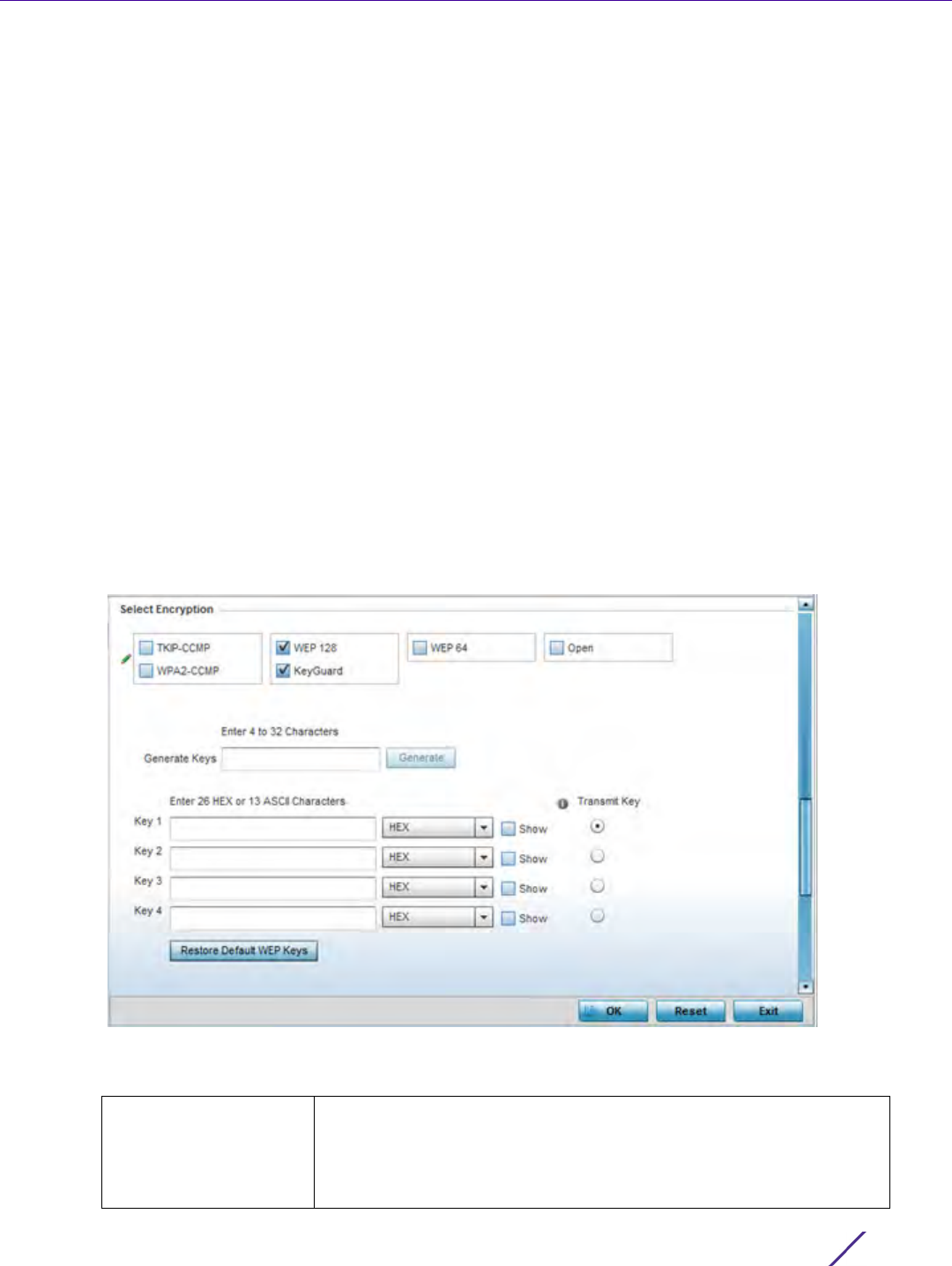
Wireless Configuration
Wireless Controller and Service Platform System Reference Guide 6 - 24
• Additional layers of security (beyond WEP) should be enabled to minimize the likelihood of data loss and
security breaches. WEP enabled WLANs should be mapped to an isolated VLAN with firewall policies restricting
access to hosts and suspicious network applications.
• WEP enabled WLANs should only be permitted access to resources required by legacy devices.
• If WEP support is needed for WLAN legacy device support, 802.1X EAP authentication should be also
configured in order for the WLAN to provide authentication and dynamic key derivation and rotation.
6.1.2.12 Keyguard
Configuring WLAN Security
Keyguard is a form of WEP, and could be all a small business needs for the simple encryption of wireless data.
KeyGuard is a proprietary encryption method, and an enhancement to WEP encryption, and was developed before
the finalization of WPA-TKIP. The Keyguard encryption implementation is based on the IEEE Wi-Fi standard, 802.11i.
To configure Keyguard encryption on a WLAN:
1Select
Configuration > Wireless > Wireless LAN Policy to display available WLANs.
2 Select the Add button to create an additional WLAN or select Edit to modify the properties of an WLAN.
3Select
Security.
4 Select the Keyguard check box from within the Select Encryption field.
The screen populates with the parameters required to define a KeyGuard configuration for the WLAN.
Figure 6-16 WLAN KeyGuard Configuration screen
5 Configure the following Keyguard settings:
Generate Keys Specify a 4 to 32 character Pass Key and click the Generate button. The
pass key can be any alphanumeric string. Clients use the algorithm to
convert an ASCII string to the same hexadecimal number. Clients
without adapters need to use keys manually configured as hexadecimal
numbers.

Wireless Configuration
Wireless Controller and Service Platform System Reference Guide 6 - 25
Default WEP Keyguard keys are as follows:
• Key 1 101112131415161718191A1B1C
• Key 2 202122232425262728292A2B2C
• Key 3 303132333435363738393A3B3C
• Key 4 404142434445464748494A4B4C
6Select
OK when completed to update the WLAN’s Keyguard encryption configuration. Select Reset to revert the
screen back to its last saved configuration.
KeyGuard Deployment Considerations
Keyguard
Before defining a Keyguard configuration on a WLAN, refer to the following deployment guidelines to ensure the
configuration is optimally effective:
• Authentication techniques can also be enabled on WLANs supporting other proprietary techniques, such as
KeyGuard.
• A WLAN using KeyGuard to support legacy devices should also use largely limited to the support of just those
legacy clients using KeyGuard.
6.1.2.13 T5 Controller Security
Configuring WLAN Security
A T5 controller, once enabled as a supported external device, can provide data to WiNG to assist in a T5’s
management within a WiNG supported subnet populated by both types of devices. The Customer Premises
Equipment (CPEs) are the T5 controller managed radio devices. These CPEs use Digital Subscriber Line (DSL) as
their high speed Internet access mechanism using the CPE’s physical wallplate connection and phone jack.
To configure WLAN security settings for a T5 controller and its connected CPEs:
1Select
Configuration > Wireless > Wireless LAN Policy to display available WLANs.
2 Select the Add button to create an additional WLAN or select Edit to modify the properties of an WLAN.
3Select
Security.
4 Refer to the T5 PowerBroadband Security field at the bottom of the screen.
Keys 1-4 Use the Key #1-4 areas to specify key numbers. For Keyguard (104-bit
key), the keys are 26 hexadecimal characters in length. Select one of
these keys for default activation by clicking its radio button. Selecting
Show displays a key in exposed plain text.
Restore Default WEP
Keys
If you feel it necessary to restore the Keyguard algorithm back to its
default settings, click the Restore Default WEP Keys button. This may
be the case if the latest defined algorithm has been compromised and
no longer provides its former measure of data security.
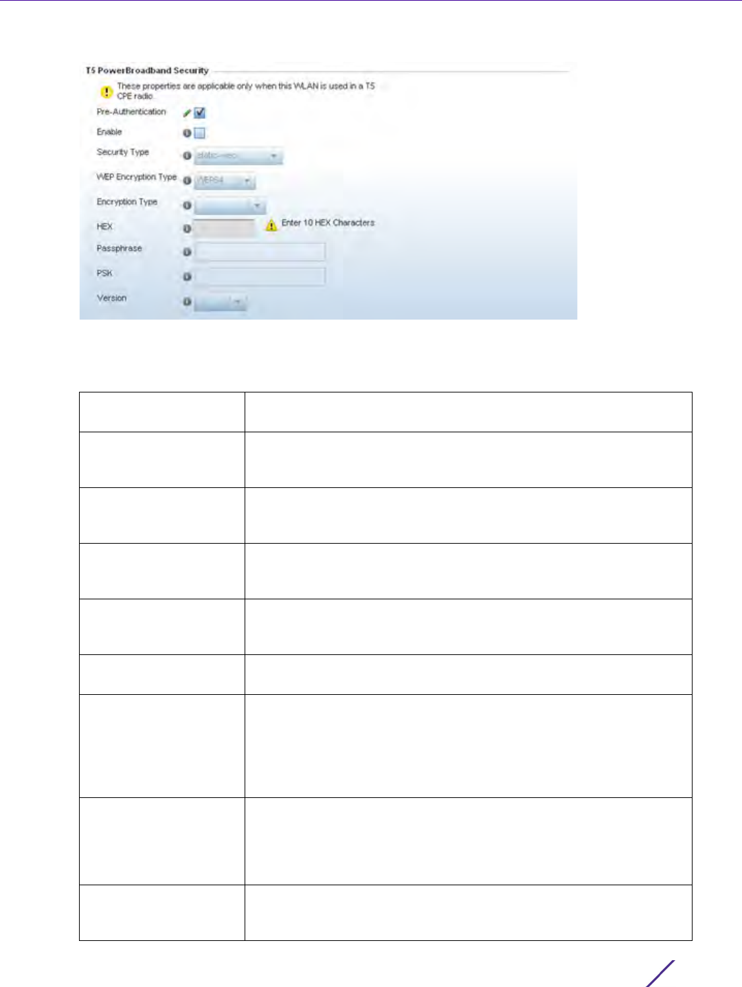
Wireless Configuration
Wireless Controller and Service Platform System Reference Guide 6 - 26
Figure 6-17 T5 PowerBroadband Security screen
5 Configure the following T5 PowerBroadband Security settings (available only when the WLAN supports T5
controllers and their connected CPEs radio devices):
Pre-Authentication Select this option to invoke the use of pre-authentication 802.11i fast
roaming. This setting is disabled by default.
Enable Select this option to enable the Security Type and WEP Encryptions
Type drop-down menus used to define and apply different encryption
and authentication settings to the T5 WLAN security configuration.
Security Type Use the drop-down menu to select the security type to apply to the
WLAN. Options include static-wep (default), wpa-enterprise and wpa-
personal.
WEP Encryption Type If static-wep is selected as the Encryption Type, use this setting to
apply either a WEP64 or WEP128 encryption algorithm to the T5
support WLAN configuration.
Encryption Type If wpa-enterprise or wpa-personal are selected as the Encryption Type,
use this setting to apply either a CCMP, TKIP or TKIP-CCMP encryption
algorithm to the T5 controller WLAN security configuration.
HEX If using static-wep, provide the 10-26 character Hex password used to
derive the security key.
Passphrase If using static-wep, enter either an alphanumeric string of 8 to 63 ASCII
characters or 64 HEX characters as the primary string both transmitting
and receiving authenticators must share. The alphanumeric string
allows character spaces. The string is converted into a numeric value.
This passphrase saves the administrator from entering the 256-bit key
each time keys are generated.
PSK Enter either an alphanumeric string as the primary string both
transmitting and receiving authenticators must share. The alphanumeric
string allows character spaces. The string is converted into a numeric
value. This passphrase saves the administrator from entering the 256-
bit key each time keys are generated.
Version If wpa-enterprise or wpa-personal are selected as the Encryption Type,
use this setting to apply a WPA or WPA2 encryption scheme to the T5
support WLAN configuration.

Wireless Configuration
Wireless Controller and Service Platform System Reference Guide 6 - 27
6Select OK when completed to update the T5 PowerBroadband Security configuration. Select Reset to revert the
screen back to its last saved configuration.
6.1.3 Configuring WLAN Firewall Support
Wireless LAN Policy
A firewall is a mechanism enforcing access control, and is considered a first line of defense in protecting
proprietary information within the network. The means by which this is accomplished varies, but in principle, a
firewall can be thought of as mechanisms both blocking and permitting data traffic. For an overview of firewalls,
see Wireless Firewall on page 10-1.
WLANs use firewalls like Access Control Lists (ACLs) to filter/mark packets based on the WLAN from which they
arrive, as opposed to filtering packets on Layer 2 ports. An ACL contains an ordered list of Access Control Entries
(ACEs). Each ACE specifies an action and a set of conditions (rules) a packet must satisfy to match the ACE. The
order of conditions in the list is critical since filtering is stopped after the first match.
IPv4 and IPv6 based firewall rules are specific to source and destination IP addresses and the unique rules and
precedence orders assigned. Both IP and non-IP traffic on the same Layer 2 interface can be filtered by applying
both an IP ACL and a MAC.
Additionally, administrators can filter Layer 2 traffic on a physical Layer 2 interface using MAC addresses. A MAC
firewall rule uses source and destination MAC addresses for matching operations, where the result is a typical
allow, deny or mark designation to WLAN packet traffic.
Keep in mind IP and non-IP traffic on the same Layer 2 interface can be filtered by applying both an IP ACL and a
MAC ACL to the interface.
To review access policies, create a new policy or edit the properties of an existing policy:
1Select
Configuration > Wireless LANs > Wireless LAN Policy to display available WLANs.
2 Select the Add button to create a new WLAN or Edit to modify the properties of an existing WLAN.
3Select
Firewall from the Wireless LAN Policy options.
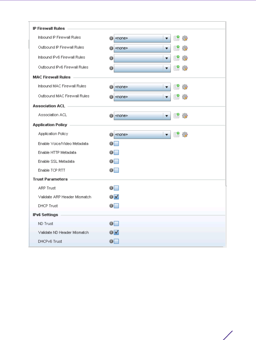
Wireless Configuration
Wireless Controller and Service Platform System Reference Guide 6 - 28
Figure 6-18 WLAN Policy Firewall screen
The screen displays editable fields for IP Firewall Rules, MAC Firewall Rules, Trust Parameters, IPv6 Settings and
Wireless Client Deny limits.
Select an existing Inbound IP Firewall Rule and Outbound IP Firewall Rule using the drop-down menu. If no
rules exist, select the Create icon to display a screen where Firewall rules can be created. Select the Edit icon to
modify the configuration of a selected Firewall policy configuration.
4 If creating a new IP firewall rule, provide a name up to 32 characters.
5 Select the Add button.
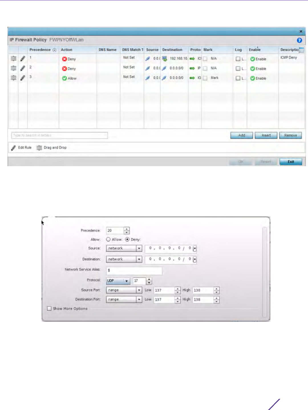
Wireless Configuration
Wireless Controller and Service Platform System Reference Guide 6 - 29
Figure 6-19 IP Firewall Rules screen
6 IP firewall rule configurations can either be modified as a collective group of variables or selected and updated
individually as their filtering attributes require a more refined update.
a. Select the Edit Rule icon to the left of a particular IP firewall rule configuration to update its parameters
collectively.
Figure 6-20 IP Firewall Rules Add Criteria screen
b. Click the icon within the Description column (top right-hand side of the screen) and select IP filter values as
needed to add criteria into the configuration of the IP ACL.
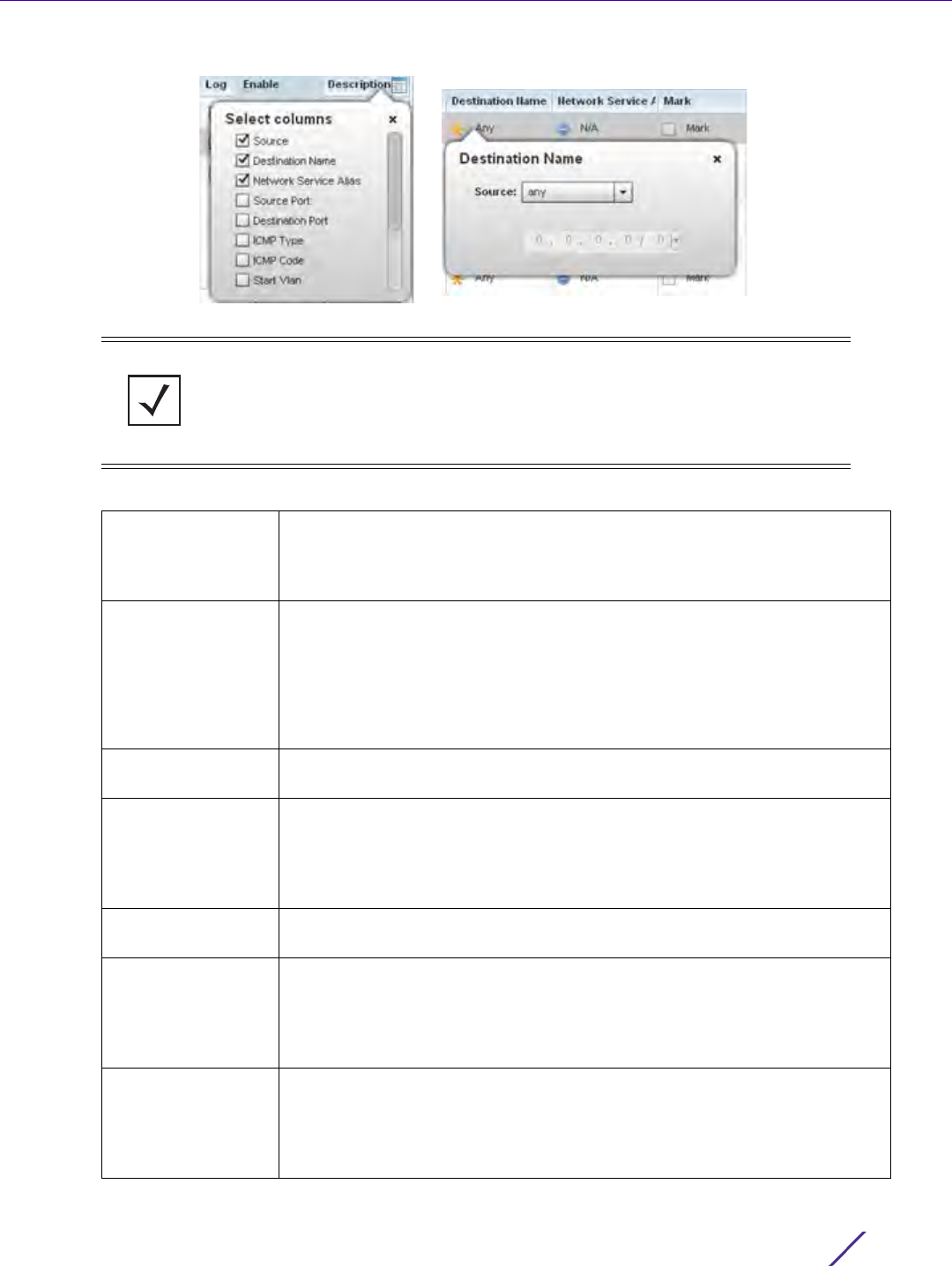
Wireless Configuration
Wireless Controller and Service Platform System Reference Guide 6 - 30
Figure 6-21 IP Firewall Rules Add Criteria screen
7 Define the following IP firewall rule settings as required:
NOTE: Only those selected IP ACL filter attributes display. Each value can have its
current setting adjusted by selecting that IP ACL’s column to display a pop-up to
adjust that one value.
Precedence Specify or modify a precedence for this IP policy between 1-5000. Rules
with lower precedence are always applied to packets first. If modifying a
precedence to apply a higher integer, it will move down the table to reflect
its lower priority.
Action Every IP Firewall rule is made up of matching criteria rules. The action
defines the packet’s disposition if it matches the specified criteria. The
following actions are supported:
Deny - Instructs the Firewall to restrict a packet from proceeding to its
destination.
Allow - Instructs the Firewall to allow a packet to proceed to its destination.
DNS Name Specify the DNS Name which may be a full domain name, a portion of a
domain name or a suffix. This name is used for the DNS Match Type criteria.
DNS Match Type Specify the DNS matching criteria that the DNS Name can be matched
against. This can be configured as an exact match for a DNS domain name,
a suffix for the DNS name or a domain that contains a portion of the DNS
name. If traffic matches the configured criteria in the DNS Match Type, that
rule will be applied to the ACL.
Source Select the source IP address or network group configuration used as basic
matching criteria for this IP ACL rule.
Destination Determine whether filtered packet destinations for this IP firewall rule do
not require any classification (any), are designated as a set of
configurations consisting of protocol and port mappings (an alias), set as a
numeric IP address (host) or defined as network IP and mask. Selecting
alias requires a destination network group alias be available or created.
Network Service
Alias
The service alias is a set of configurations consisting of protocol and port
mappings. Both source and destination ports are configurable. Set an
alphanumeric service alias (beginning with a $) and include the protocol as
relevant. Selecting either tcp or udp displays an additional set of specific
TCP/UDP source and destinations port options.

Wireless Configuration
Wireless Controller and Service Platform System Reference Guide 6 - 31
8 Select existing inbound and outbound MAC Firewall Rules using the drop-down menu. If no rules exist, select
Create to display a screen where Firewall rules can be created. MAC firewall rules can also be applied to an
EX3500 Ethernet PoE switch connected and utilized by a WiNG managed device.
9 Select the + Add Row button.
10 Select the added row to expand it into configurable parameters.
Source Port If using either tcp or udp as the protocol, define whether the source port
for incoming IP ACL rule application is any, equals or an administrator
defined range. If not using tcp or udp, this setting displays as N/A. This is
the data local origination port designated by the administrator. Selecting
equals invokes a spinner control for setting a single numeric port. Selecting
range displays spinner controls for Low and High numeric range settings. A
source port cannot be a destination port.
Destination Port If using either tcp or udp as the protocol, define whether the destination
port for outgoing IP ACL rule application is any, equals or an administrator
defined range. If not using tcp or udp, this setting displays as N/A. This is
the data destination virtual port designated by the administrator. Selecting
equals invokes a spinner control for setting a single numeric port. Selecting
range displays spinner controls for Low and High numeric range settings.
ICMP Type Selecting ICMP as the protocol for the IP rule displays an additional set of
ICMP specific options for ICMP type and code. The Internet Control
Message Protocol (ICMP) uses messages identified by numeric type. ICMP
messages are used for packet flow control or generated in IP error
responses. ICMP errors are directed to the source IP address of the
originating packet. Assign an ICMP type from 1-10.
ICMP Code Selecting ICMP as the protocol for the IP rule displays an additional set of
ICMP specific options for ICMP type and code. Many ICMP types have a
corresponding code, helpful for troubleshooting network issues (0 - Net
Unreachable, 1 Host Unreachable, 2 Protocol Unreachable etc.).
Start VLAN Select a Start VLAN icon within a table row to set (apply) a start VLAN
range for this IP ACL filter. The Start VLAN represents the virtual LAN
beginning numeric identifier arriving packets must adhere to in order to
have the IP ACL rules apply.
End VLAN Select an End VLAN icon within a table row to set (apply) an end VLAN
range for this IP ACL filter. The End VLAN represents the virtual LAN end
numeric identifier arriving packets must adhere to in order to have the IP
ACL rules apply.
Mark Select an IP Firewall rule’s Mark checkbox to enable or disable event
marking and set the rule’s 8021p or dscp level (from 0 - 7).
Log Select an IP Firewall rule’s Log checkbox to enable or disable event logging
for this rule’s usage.
Enable Select an IP Firewall rule’s Enable or Disable icon to determine this rule’s
inclusion with the IP firewall policy.
Description Lists the administrator assigned description applied to the IP ACL rule.
Select a description within the table to modify its character string as
filtering changes warrant. Select the icon within the Description table
header to launch a Select Columns screen used to add or remove IP ACL
criteria from the table.
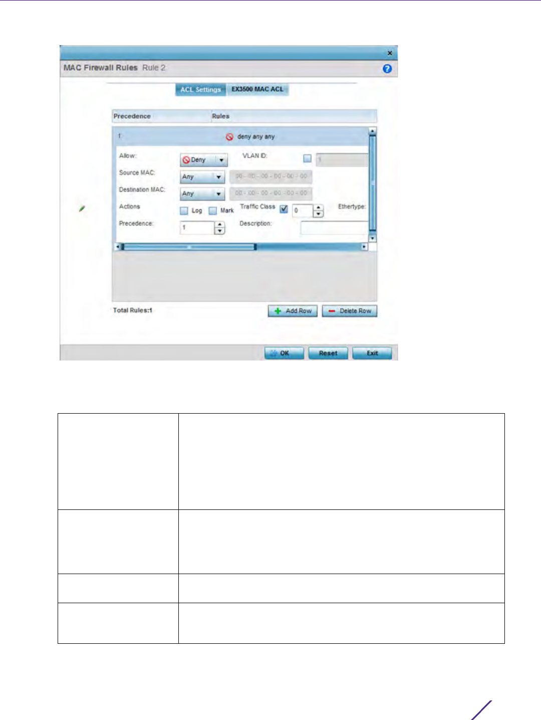
Wireless Configuration
Wireless Controller and Service Platform System Reference Guide 6 - 32
Figure 6-22 MAC Firewall Rules screen
11 Define the following parameters for either the inbound or outbound MAC Firewall Rules for either a WiNG
managed device or an EX3500 switch connected to a WiNG managed device:
Allow Every IP Firewall rule is made up of matching criteria rules. The action
defines what to do with the packet if it matches the specified criteria.
The following actions are supported:
Deny - Instructs the Firewall to deny a packet from proceeding to its
destination.
Permit - Instructs the Firewall to allow a packet to proceed to its
destination.
VLAN ID Enter a VLAN ID representative of the shared SSID each user employs
to interoperate within the network (once authenticated by the local
RADIUS server). The VLAN ID can be between 1 - 4094. EX3500 PoE
switches utilize a VLAN Mask option (from 0 - 4095) to mask the
exposure of the VLAN ID.
Match 802.1P Configures IP DSCP to 802.1p priority mapping for untagged frames.
Use the spinner control to define a setting between 0-7.
Source and Destination
MAC
Enter both Source and Destination MAC addresses. The wireless
controller uses the source IP address, destination MAC address as basic
matching criteria. Provide a subnet mask if using a mask.

Wireless Configuration
Wireless Controller and Service Platform System Reference Guide 6 - 33
12 If creating a new Association ACL, provide a name specific to its function. Avoid naming it after a WLAN it may
support. The name cannot exceed 32 characters.
13 Assign an Application Policy to the firewall and set the following metadata extraction rules:
Action The following actions are supported:
Log - Creates a log entry that a Firewall rule has allowed a packet to
either be denied or permitted.
Mark - Modifies certain fields inside the packet and then permits them.
Therefore, mark is an action with an implicit permit.
Mark, Log - Conducts both mark and log functions.
Traffic Class Sets an ACL traffic classification value for the packets identified by this
inbound MAC filter. Traffic classifications are used for QoS purposes.
Use the spinner to define a traffic class from 1- 10.
Ethertype Use the drop-down menu to specify an Ethertype of either ipv6, arp,
wisp or monitor 8021q. An EtherType is a two-octet field within an
Ethernet frame. It is used to indicate which protocol is encapsulated in
the payload of an Ethernet frame. EX3500 PoE switches utilize an Ether
Mask option (from 0 - 65535) to mask the exposure of the Ethertype.
Precedence Use the spinner control to specify a precedence for this MAC Firewall
rule between 1-1500. Access policies with lower precedence are always
applied first to packets.
Description Provide an ACL setting description (up to 64 characters) for the rule to
help differentiate the it from others with similar configurations.
Application Policy Use the drop-down menu to assign an application policy to the WLAN’s
firewall configuration. When an application is recognized and classified
by the WiNG application recognition engine, administrator defined
actions can be applied to that specific application. An application policy
defines the rules or actions executed on recognized HTTP, SSL and
voice/video applications. For more information, refer to Application on
page 7-58.
Voice/Video Metadata Select this option to enable the extraction of voice and video metadata
flows. When enabled, administrators can track voice and video calls by
extracting parameters (packets transferred and lost, jitter, audio codec
and application name). Most Enterprise VoIP applications like facetime,
skype for business and VoIP terminals can be monitored for call quality
and visualized on the NSight dashboard in manner similar to HTTP and
SSL. Call quality and metrics can only be determined from calls
established unencrypted. This setting is disabled by default.
HTTP Metadata Select this option to enable the extraction of HTTP flows. When
enabled, administrators can track HTTP Websites accessed by both
internal and guest clients and visualize HTTP data usage, hits, active
time and total clients on the NSight application’s dashboard. This
setting is disabled by default.
SSL Metadata Select this option to enable the extraction of SSL flows. When enabled,
administrators can track SSL Websites accessed by both internal and
guest clients and visualize SSL data usage, hits, active time and total
clients on the NSight application’s dashboard.This setting is disabled by
default.

Wireless Configuration
Wireless Controller and Service Platform System Reference Guide 6 - 34
14 Set the following Trust Parameters:
15 Set the following IPv6 Settings:
16 Set the following Wireless Client Deny configuration:
17 Set a Firewall Session Hold Time in either Seconds (1 - 300) or Minutes (1 - 5). This is the hold time for caching
user credentials and firewall state information when a client roams. The default setting is 30 seconds.
Enable TCP RTT Select this option to enable the extraction of Round Trip Time (RTT)
from Transmission Control Protocol (TCP) flows. When enabled, the RTT
information from TCP flows detected on the VLAN interface associated
with the WLAN is extracted and forwarded to the NSight server by
Access Points. However, this TCP-RTT metadata is viewable only on the
NSight dashboard. Therefore, ensure the NSight server is up, an NSight
policy (pointing to the NSight server) is applied on the Access Point’s
RF Domain, and NSight analytics data collection is enabled. This setting
is disabled by default.
ARP Trust Select the check box to enable ARP Trust on this WLAN. ARP packets
received on this WLAN are considered trusted and information from
these packets is used to identify rogue devices within the network. This
setting is disabled by default.
Validate ARP Header
Mismatch
Select this option to verify the mismatch for source MAC in the ARP
and Ethernet headers. By default, mismatch verification is enabled.
DHCP Trust Select the check box to enable DHCP trust on this WLAN. This setting
is disabled by default.
ND Trust Select this option to enable the trust of neighbor discovery requests on
an IPv6 supported firewall on this WLAN. This setting is disabled by
default.
Validate ND Header
Mismatch
Select this option to enable a mismatch check for the source MAC
within the ND header and Link Layer Option. This setting is enabled by
default.
DHCPv6 Trust Select this option to enable the trust all DHCPv6 responses on this
WLAN’s firewall. DHCPv6 is a networking protocol for configuring IPv6
hosts with IP addresses, IP prefixes or other configuration attributes
required on an IPv6 network. This setting is disabled by default.
RA Guard Select this option to enable router advertisements or ICMPv6 redirects
on this WLAN’s firewall. This setting is disabled by default.
Wireless Client Denied
Traffic Threshold
If enabled, any associated client which exceeds the thresholds
configured for storm traffic is either deauthenticated or blacklisted
depending on the selected action. The threshold range is 1-1000000
packets per second. This feature is disabled by default.
Action If enabling a wireless client threshold, use the drop-down menu to
determine whether clients are deauthenticated when the threshold is
exceeded or blacklisted from connectivity for a user defined interval.
Selecting None applies no consequence to an exceeded threshold.
Blacklist Duration Select the check box and define a setting between 0 - 86,400 seconds.
Once the blacklist duration has been exceeded, offending clients can
reauthenticate once again.
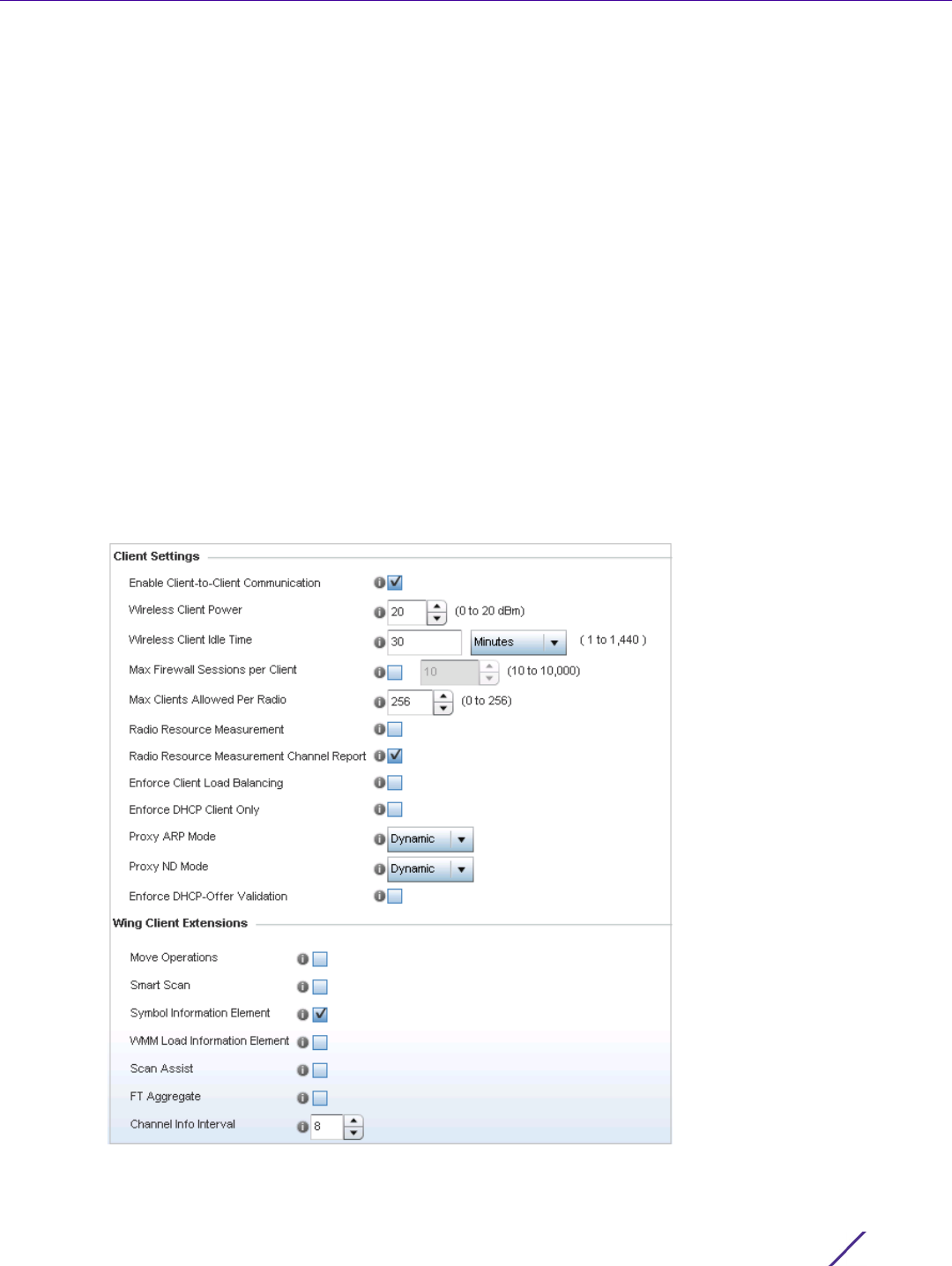
Wireless Configuration
Wireless Controller and Service Platform System Reference Guide 6 - 35
18 Select OK when completed to update this WLAN’s Firewall settings. Select Reset to revert the screen back to its
last saved configuration.
WLAN Firewall Deployment Considerations
Before defining an access control configuration on a WLAN, refer to the following deployment guidelines to ensure
the configuration is optimally effective:
• IP and non-IP traffic on the same Layer 2 interface can be filtered by applying both an IP ACL and a MAC ACL
to the interface.
6.1.4 Configuring Client Settings
Wireless LAN Policy
Each WLAN can maintain its own unique client support configuration. These include wireless client inactivity
timeouts and broadcast settings.
1Select
Configuration > Wireless > Wireless LAN Policy to display available WLANs.
2 Select the Add button to create an additional WLAN, or select and existing WLAN and Edit to modify its
properties.
3 Select the Client Settings tab.
Figure 6-23 WLAN Policy Client Settings screen

Wireless Configuration
Wireless Controller and Service Platform System Reference Guide 6 - 36
4 Define the following Client Settings for the WLAN:
Enable
Client-to-Client
Communication
Select this option to enable client to client communication within this
WLAN. The default is enabled, meaning clients are allowed to
exchange packets with other clients. It does not necessarily prevent
clients on other WLANs from sending packets to this WLAN, but as
long as this setting also disabled on that WLAN, clients are not
permitted to interoperate.
Wireless Client Power Use this parameter to set the maximum transmit power (between 0 -
20 dBm) communicated to wireless clients for transmission within the
network. The default value is 20 dBm.
Wireless Client Idle Time Set the maximum amount of time wireless clients are allowed to be
idle within this WLAN. Set the idle time in either Seconds (60 -
86,400), Minutes (1 - 1,440), Hours (1 - 24) or Days (1). When this
setting is exceeded, the client is no longer able to access resources and
must re-authenticate. The default value is 1,800 seconds.
Max Firewall Sessions
per Client
Select this option to set the maximum amount of sessions (between 10
- 10,000) clients within the network over the Firewall. When enabled,
this parameter limits the number of simultaneous sessions allowed by
the Firewall per wireless client. This feature is disabled by default.
Max Clients Allowed Per
Radio
Use the spinner control to set the maximum number of clients (from 0
- 256) allowed to associate to each radio within this WLAN. The
default setting is 256.
Radio Resource
Measurement
Select this option to enable radio resource measurement capabilities
(IEEE 802.11k) on this WLAN. 802.11k improves how traffic is
distributed. In a WLAN, each device normally connects to an Access
Point with the strongest signal. Depending on the number and
locations of the clients, this arrangement can lead to excessive demand
on one Access Point and underutilization others, resulting in
degradation of overall network performance. With 802.11k, if the Access
Point with the strongest signal is loaded to its capacity, a client
connects to a underutilized Access Point. Even if the signal is weaker,
the overall throughput is greater since it’s an efficient use of the
network’s resources. This setting is disabled by default.
Radio Resource
Measurement Channel
Report
Select this option to enable radio resource measurement channel
reporting (IEEE 802.11k) on this WLAN. This setting is disabled by
default.
Enforce Client Load
Balancing
Select the check box to distribute clients evenly amongst associated
Access Point radios. This feature is disabled by default. Loads are
balanced by ignoring association and probe requests. Probe and
association requests are not responded to, forcing a client to associate
with another Access Point radio.
Enforce DHCP Client
Only
Select the check box to enforce that the firewall only allows packets
from clients if they used DHCP to obtain an IP address, disallowing
static IP addresses. This feature is disabled by default.
Proxy ARP Mode Use the drop-down menu to define the proxy ARP mode as either
Strict or Dynamic. Proxy ARP is the technique used to answer ARP
requests intended for another system. By faking its identity, the Access
Point accepts responsibility for routing packets to the actual
destination. Dynamic is the default value.

Wireless Configuration
Wireless Controller and Service Platform System Reference Guide 6 - 37
5 Define the following Wing Client Extensions to potentially increase client roaming reliability and handshake
speed:
6 Define the following Coverage Hole Detection settings to determine how detected coverage holes are managed:
Proxy ND Mode Use the drop-down menu to define the proxy neighbor discovery (ND)
mode for WLAN member clients as either Strict or Dynamic. ND Proxy
is used in IPv6 to provide reachability by allowing the a client to act as
proxy. Proxy certificate signing can be done either dynamically
(requiring exchanges of identity and authorization information) or
statically when the network topology is defined. Dynamic is the default
value.
Enforce DHCP-Offer
Validation
Select the check box to enforce DHCP offer validation. The default
setting is disabled.
Move Operations Select the check box to enable the use of Hyper-Fast Secure Roaming
(HFSR) for clients utilizing this WLAN. This feature applies only to
certain client devices. This feature is disabled by default.
Smart Scan Enable smart scan to adjust clients channel scans to a few channels as
opposed to all available channels. This feature is disabled by default.
Symbol Information
Element
Select the check box to support the Symbol Information Element with
legacy Symbol Technology clients, thus making them optimally
interoperable with the latest Extreme Networks Access Points. The
default setting is enabled.
WMM Load Information
Element
Select the check box to support a WMM Load Information Element in
radio transmissions with legacy clients. The default setting is disabled.
Scan Assist Enable scan assist to achieve faster roams on DFS channels by
eliminating passive scans. Clients would get channel information
directly from possible roam candidates. This setting is disabled by
default.
FT Aggregate Enable fast transition (FT) aggregate to increase roaming speed by
eliminating separate key exchange handshake frames with potential
roam candidates. Enable fast transition to complete an initial FT over
DS handshake with multiple roam candidates (up to 6) at once,
eliminating the need to send separate FT over DS handshakes to each
roam candidate. This setting is disabled by default.
Channel Info Interval Configure the channel information interval to periodically retrieve
channel information directly from potential roam candidates without
making a scan assist request.
Enable Enable this setting to inform an Access Point when it experiences a
coverage hole (area of poor wireless coverage). This setting is disabled
by default.
Use 11k Clients Optionally enable this setting to also use 802.11k-only-capable clients
to detect coverage holes. This is a reduced set of coverage hole
detection capabilities (only standard 11k messages and behaviors). This
setting is disabled by default.
Threshold Use the spinner control to set the Access Point signal strength (as seen
by the client) below which a coverage hole incident is reported. The
threshold can be set from -80 to -60.

Wireless Configuration
Wireless Controller and Service Platform System Reference Guide 6 - 38
7 Set the following AP Attributes Information:
8 Define the following Timeout Settings for the WLAN:
9Select
Controller Assisted Mobility, within the Mobility field, to use a controller or service platform’s mobility
database to assist in roaming between RF Domains. This feature is disabled by default.
10 Use the Device ID settings, within the OpenDNS field, to specify a 16 character maximum OpenDNS device ID
forwarded in a DNS query. OpenDNS extends DNS by adding additional features such as misspelling correction,
phishing protection, and optional content filtering.
11 Select Client Isolation, within the T5 PowerBroadband Client Settings field, to disallow clients connecting to the
WLAN to communicate with one another. This setting applies exclusively to CPE devices managed by a T5
controller and is disabled by default.
Use the Inactivity Time Out field to define the inactivity timeout specific to T5 clients. Set the maximum
amount of time T5 clients are allowed to be idle within this WLAN. Set the idle time in either Seconds (60 -
86,400), Minutes (1 - 1,440), Hours (0 - 24) or Days (0 - 1). When this setting is exceeded, the client is no
longer able to access resources and must reauthenticate. The default value is 1,800 seconds.
A T5 controller, once enabled as a supported external device, can provide data to WiNG to assist in a T5’s
management within a WiNG supported subnet populated by both types of devices. The Customer Premises
Equipment (CPEs) are the T5 controller managed radio devices. These CPEs use a Digital Subscriber Line (DSL)
as their high speed Internet access mechanism using the CPE’s physical wallplate connection and phone jack.
12 Select OK when completed to update the WLAN’s client setting configuration. Select Reset to revert the screen
back to the last saved configuration.
6.1.4.1 WLAN Client Setting Deployment Considerations
Configuring Client Settings
Before defining a WLAN’s client settings, refer to the following deployment guidelines to ensure the configuration
is optimally effective:
• Clients on the same WLAN associated with an AAP can communicate locally at the AP Level without going
through the controller or service platform. If this is undesirable, an Access Point's
Client-to-Client Communication option should be disabled.
• When the wireless client idle time setting is exceeded, the client is no longer able to access WLAN resources
and must re-authenticate. The default value is 1,800 seconds.
Offset Use the spinner control to set the offset added to the threshold to
obtain the Access Point signal strength (as seen by the client)
considered adequate. The offset can be set from 5 to 20.
Enable Select this option to include the AP-Attributes information element in
the beacon. The information element helps clients recognize which
wing-extensions are supported by the AP. This setting is enabled by
default.
Include Hostname Select this option to include the AP's hostname in the AP-Attributes
information element. This setting is disabled by default.
Credential Cache
Timeout
Set a timeout period for the credential cache in Days, Hours, Minutes
or Seconds.
VLAN Cache Timeout Set a timeout period for the VLAN cache in Days, Hours, Minutes or
Seconds.
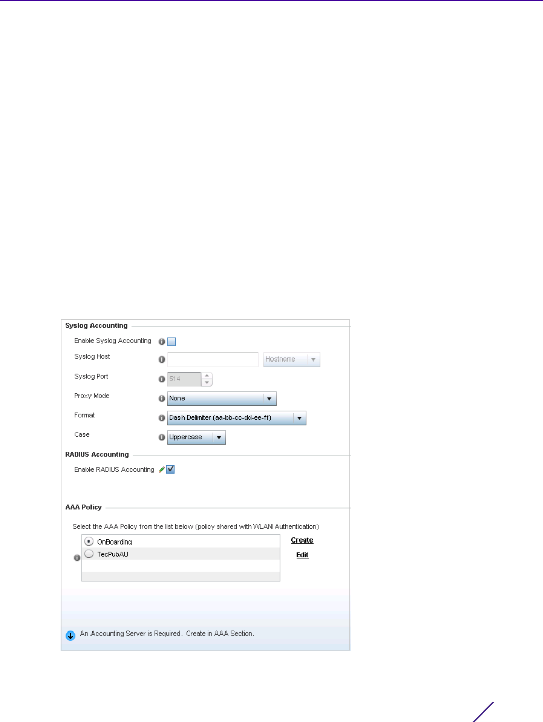
Wireless Configuration
Wireless Controller and Service Platform System Reference Guide 6 - 39
6.1.5 Configuring WLAN Accounting Settings
Accounting is the method of collecting and sending security server information for billing, auditing, and reporting
user data; such as start and stop times, executed commands (such as PPP), number of packets and number of
bytes. Accounting enables wireless network administrators to track the services users are accessing and the
network resources they are consuming. When accounting is enabled, the network access server reports and logs
user activity to a RADIUS security server in the form of accounting records. Each accounting record is comprised
of AV pairs and is stored on a local access control server. The data can be analyzed for network management,
client billing, and/or auditing. Accounting methods must be defined through AAA.
Accounting can be enabled and applied to WLANs, to uniquely log accounting events specific to the WLAN.
Accounting logs contain information about the use of remote access services by users. This information is of great
assistance in partitioning local versus remote users and how to best accommodate each. Remote user information
can be archived to an external location for periodic network and user permission administration.
To configure WLAN accounting settings:
1Select
Configuration > Wireless LANs > Wireless LAN Policy to display available WLANs.
2 Select the Add button to create an additional WLAN or select Edit to modify the properties of an existing
WLAN.
3Select
Accounting.
Figure 6-24 WLAN Policy Accounting screen

Wireless Configuration
Wireless Controller and Service Platform System Reference Guide 6 - 40
4 Set the following System Log Accounting information:
5 Select the Enable RADIUS Accounting check box to use an external RADIUS resource for AAA accounting.
When the check box is selected, a AAA Policy field displays. Either use the default AAA policy with the WLAN,
or select Create to define a new AAA configuration that can be applied to the WLAN. This setting is disabled by
default.
6Select
OK when completed to update this WLAN’s accounting settings. Select Reset to revert the screen to its
last saved configuration.
6.1.5.1 Accounting Deployment Considerations
Before defining a WLAN AAA configuration, refer to the following deployment guidelines to ensure the
configuration is optimally effective:
• When using RADIUS authentication, the WAN port round trip delay should not exceed 150ms. Excessive delay
over a WAN can cause authentication and roaming issues. When excessive delays exists, a distributed RADIUS
service should be used.
• Authorization policies should be implemented when users need to be restricted to specific WLANs, or time and
date restrictions need to be applied.
• Authorization policies can also apply bandwidth restrictions and assign Firewall policies to users and devices.
6.1.6 Configuring WLAN Service Monitoring Settings
Wireless LAN Policy
Service Monitoring is a mechanism for administrating external AAA server, captive portal server, Access Point
adoption, and DHCP server activity for WLANs. Service monitoring enables an administrator to better notify users
of a service’s availability and make resource substitutions. Service monitoring can be enabled and applied to log
activity as needed for specific WLANs.
External services can be rendered unavailable due to any of the following instances:
• When the RADIUS authentication server becomes unavailable. The RADIUS server could be local or external
to the controller, service platform or Access Point.
Enable Syslog
Accounting
Use this option to generate accounting records in standard syslog
format (RFC 3164). The feature is disabled by default.
Syslog Host Specify the IP address or hostname of the external syslog host where
accounting records are routed. Hostnames cannot include an
underscore character.
Syslog Port Use the spinner control to set the destination UDP port number of the
external syslog host where the accounting records are routed.
Proxy Mode If a proxy is needed to connect to the syslog server choose a proxy
mode of Through RF Domain Manager or Through Wireless Controller.
If no proxy is needed, select None.
Format Specify the delimiter format for the MAC address to be packed in the
syslog request. Available formats are No Delimiter (aabbccddeeff),
Colon Delimiter (aa:bb:cc:dd:ee:ff), Dash Delimiter (aa-bb-cc-dd-ee-ff),
Dot Delimiter (aabb.ccdd.eeff) and Middle Dash Delimiter (aabbcc-
ddeeff).
Case Specify to send the MAC addresses in either Uppercase or Lowercase
for syslog requests.
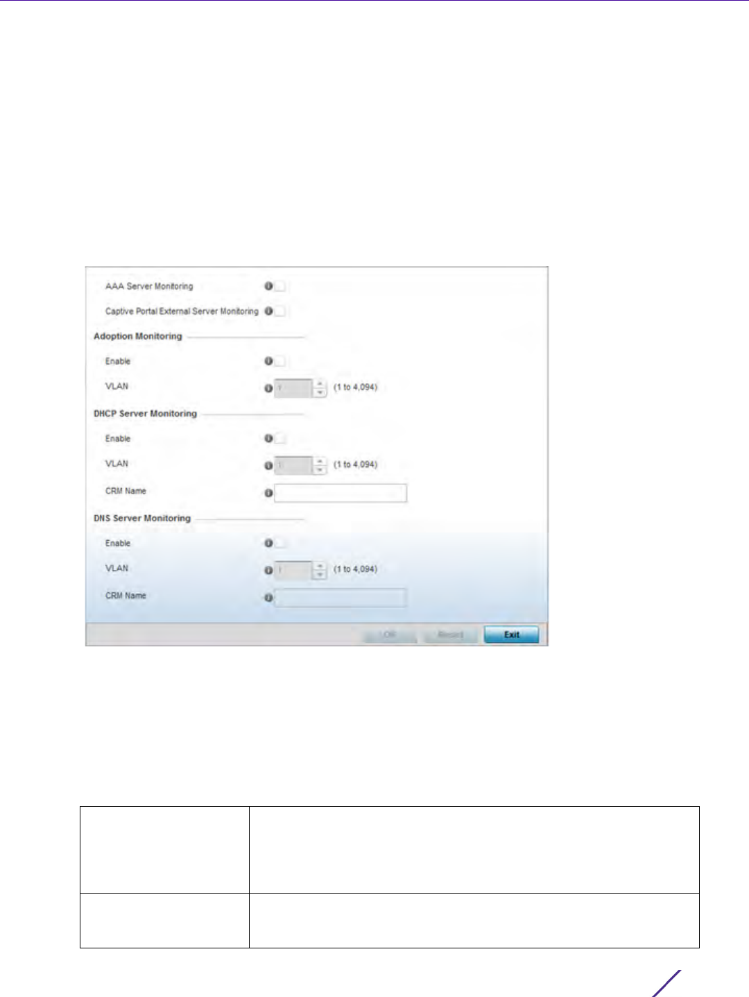
Wireless Configuration
Wireless Controller and Service Platform System Reference Guide 6 - 41
• When an externally hosted captive portal is unavailable (for any reason)
• If an Access Point’s connected controller or service platform becomes unavailable
• When a monitored DHCP server resource becomes unavailable
To configure WLAN service monitoring:
1Select
Configuration > Wireless LANs > Wireless LAN Policy to display a high-level display of the existing
WLANs.
2 Select the Add button to create an additional WLAN or select Edit to modify the properties of an existing
WLAN.
3Select
Service Monitoring.
Figure 6-25 WLAN Policy Service Monitoring screen
4 Select the AAA Server monitoring option to monitor a dedicated external RADIUS server and ensure its
adoption resource availability. This setting is disabled by default.
5 Select the Captive Portal External Server monitoring option to monitor externally hosted captive portal activity,
and temporary and restrictive user access to the controller or service platform managed network. This setting is
disabled by default.
6 Refer to the Adoption Monitoring field to set the WLAN’s adoption service monitoring configuration.
Enable Enable adoption monitoring to check Access Point adoptions to the
controller or service platform. When the connection is lost, captive
portal users are migrated to a defined VLAN. This feature is disabled
by default, so it must be enabled to monitor WLAN specific adoption
data.
VLAN Select the VLAN users are migrated to when an Access Point’s
connection to its adopting controller or service platform is lost. The
available range is from 1 - 4,094.

Wireless Configuration
Wireless Controller and Service Platform System Reference Guide 6 - 42
7 Refer to the DHCP Server Monitoring field to set the WLAN’s adoption service monitoring configuration.
8 Refer to the DNS Server Monitoring field to set the WLAN’s DNS service monitoring configuration.
9Select
OK when completed to update this WLAN’s service monitor settings. Select Reset to revert the screen
back to its last saved configuration.
6.1.7 Configuring Client Load Balancing Settings
Wireless LAN Policy
To configure WLAN client load balance settings:
1Select
Configuration > Wireless LANs > Wireless LAN Policy to display a high-level display of the existing
WLANs.
2 Select the Add button to create an additional WLAN or select Edit to modify the properties of an existing
wireless controller WLAN.
3Select
Client Load Balancing.
Enable Select enable to monitor activity over the defined DHCP Server. When
the connection to the DHCP server is lost, captive portal users are
automatically migrated a defined VLAN. The feature is disabled by
default.
VLAN Select the VLAN users are migrated to when the defined DHCP server
resource becomes unavailable. The available range is from 1 - 4,094.
CRM Name Enter the DHCP server to monitor for availability. When this DHCP
server resource becomes unavailable, the device falls back to defined
VLAN. This VLAN has a DHCP server configured that provides a pool
of IP addresses and with a lease time less than the main DHCP server.
Enable Select enable to monitor activity over the defined DNS Server. When
the connection to the DNS server is lost, captive portal users are
automatically migrated a defined VLAN. The feature is disabled by
default.
VLAN Select the VLAN users are migrated to when the defined DNS server
resource becomes unavailable. The available range is from 1 - 4,094.
CRM Name Enter the DNS server to monitor for availability. When this DNS server
resource becomes unavailable, the device falls back to defined VLAN.
This VLAN has a DNS server configured that provides DNS address
resolution till the main DNS server becomes available.
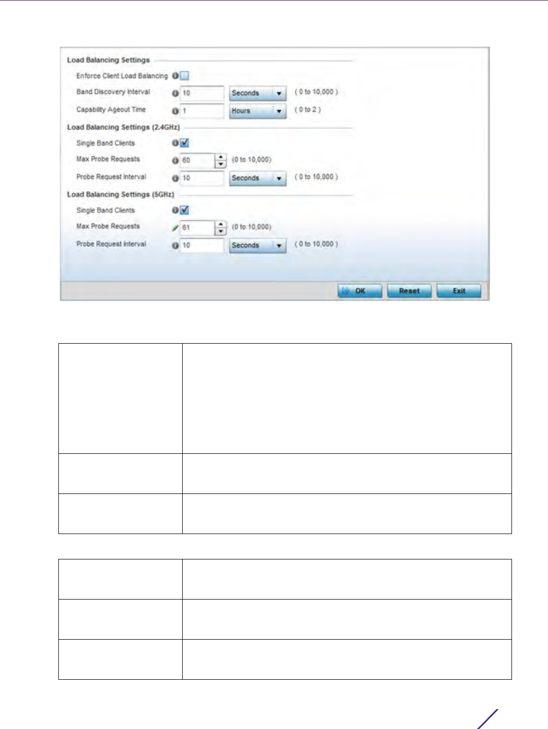
Wireless Configuration
Wireless Controller and Service Platform System Reference Guide 6 - 43
Figure 6-26 WLAN Policy Client Load Balancing screen
4 Refer to the Load Balancing Settings section to configure load balancing for the WLAN.
5 Refer to the Load Balancing Settings (2.4GHz) section to configure load balancing for the 2.4 GHz WLAN.
Enforce Client Load
Balancing
Select this option to enforce a client load balance distribution on this
WLAN’s Access Point radios. AP6522, AP6532, AP6562, AP7161,
AP7602, AP7622, AP81XX and AP8232 models can support 256 clients
per Access Point. AP6521 model can support up to 128 clients per
Access Point. AP7612, AP7632, AP7662 models can support 512 clients
per Access Point. Loads are balanced by ignoring association and
probe requests. Probe and association requests are not responded to,
forcing a client to associate with another Access Point radio.This
setting is disabled by default.
Band Discovery Interval Enter a value (from 0 - 10,000 seconds) to set the interval dedicated
to discover a client’s radio band capability before its Access Point radio
association. The default setting is 24 seconds.
Capability Ageout Time Define a value in either Seconds (0 - 10,000), Minutes (0 -166) or
Hours (0 -2) to ageout a client’s capabilities from the internal table.
The default is 24 seconds.
Single Band Clients Select this option to enable association for single band clients on the
2.4GHz frequency, even if load balancing is available. This setting is
enabled by default.
Max Probe Requests Enter a value from 0 - 10,000 for the maximum number of probe
requests for clients using the 2.4GHz frequency. The default value is
60.
Probe Request Interval Enter a value in seconds between 0 - 10,000 to configure the interval
for client probe requests beyond which it is allowed to associate for
clients on the 2.4GHz network. The default is 10 seconds.

Wireless Configuration
Wireless Controller and Service Platform System Reference Guide 6 - 44
6 Refer to the Load Balancing Settings (5GHz) section to configure load balancing for the 5 GHz WLAN.
7Select
OK when completed to update this WLAN’s advanced settings. Select Reset to revert the screen back to
its last saved configuration.
6.1.8 Configuring Advanced WLAN Settings
Wireless LAN Policy
To configure advanced settings on a WLAN:
1Select
Configuration > Wireless LANs > Wireless LAN Policy to display available WLANs.
2 Select the Add button to create an additional WLAN or select Edit to modify the properties of an existing
WLAN.
3Select
Advanced.
Single Band Clients Select this option to enable the association of single band clients on
5GHz, even if load balancing is available. This setting is enabled by
default.
Max Probe Requests Enter a value from 0 - 10,000 for the maximum number of probe
requests for clients using 5GHz. The default value is 60.
Probe Request Interval Enter a value in seconds from 0 - 10,000 to configure the interval for
client probe requests. When exceeded, clients can associate using
5GHz. The default setting is 10 seconds.
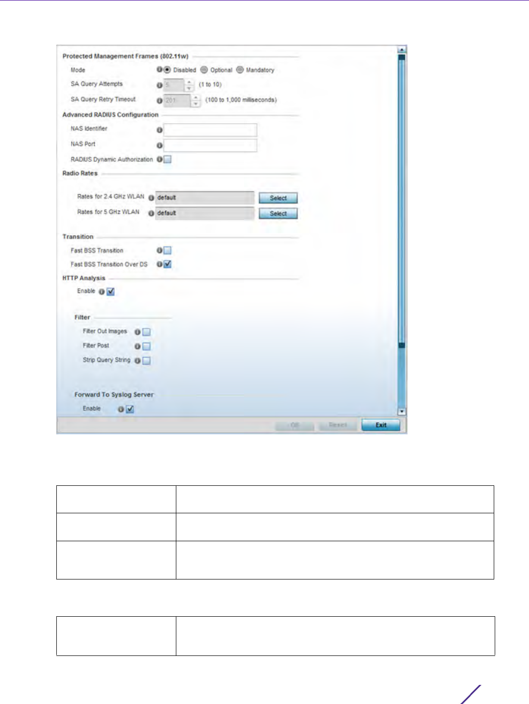
Wireless Configuration
Wireless Controller and Service Platform System Reference Guide 6 - 45
Figure 6-27 WLAN Policy Advanced screen
4 Refer to the Protected Management Frames (802.11w) field to set a frame protection mode and security
association for the WLAN’s advanced configuration.
5 Refer to the Advanced RADIUS Configuration field to set the WLAN’s NAS configuration and RADIUS Dynamic
Authorization.
Mode Select a radio button for the mode (either Disabled, Optional or
Mandatory). Disabled is the default setting.
SA Query Attempts Use the spinner control to set the number of security association
query attempts between 1-10. The default value is 5.
SA Query Retry Timeout Set the timeout (from 100-1,000 milliseconds) for waiting for a
response to a SA query before resending it. The default is 201
milliseconds.
NAS Identifier Specify what’s included in the RADIUS NAS-Identifier field for
authentication and accounting packets relating to this WLAN.
Configuring a value is optional, and defaults are used if not configured.
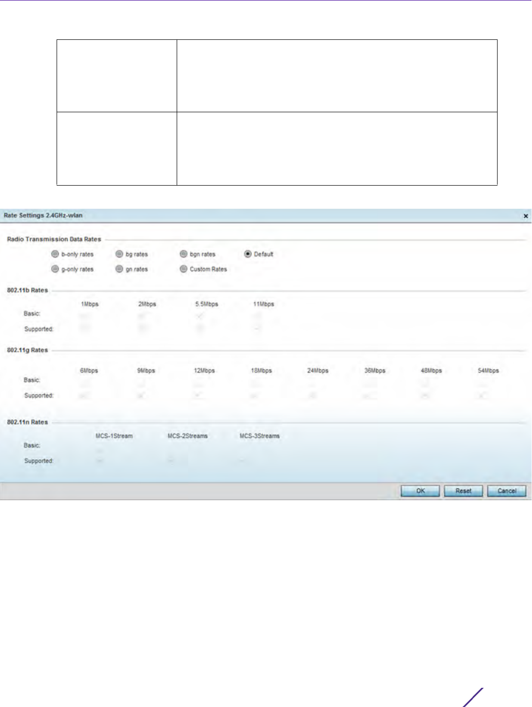
Wireless Configuration
Wireless Controller and Service Platform System Reference Guide 6 - 46
6 Refer to the Radio Rates field to define selected data rates for both the 2.4 and 5.0 GHz bands.
Figure 6-28 Advanced WLAN Rate Settings 2.4 GHz screen
NAS Port The profile database on the RADIUS server consists of user profiles for
each connected network access server (NAS) port. Each profile is
matched to a username representing a physical port. When authorizing
users, it queries the user profile database using a username
representative of the physical NAS port making the connection. Set the
numeric port value from 0-4,294,967,295.
RADIUS Dynamic
Authorization
Select the check box to enable a mechanism that extends the RADIUS
protocol to support unsolicited messages sent from the RADIUS server.
These messages allow administrators to issue change of authorization
(CoA) messages, which affect session authorization, or Disconnect
Messages (DM), which terminated a session immediately. This feature is
disabled by default.
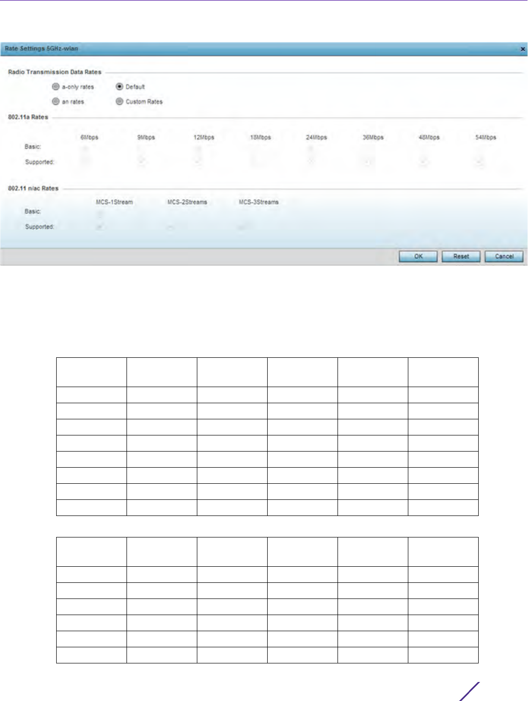
Wireless Configuration
Wireless Controller and Service Platform System Reference Guide 6 - 47
Figure 6-29 Advanced WLAN Rate Settings 5 GHz screen
Define both minimum Basic and optimal Supported rates as required for the 802.11b rates, 802.11g rates and
802.11n supported by the 2.4 GHz band and the 802.11a and 802.11n rates supported by the 5.0 GHz band.
These are the supported client rates within this WLAN.
802.11n MCS rates are defined as follows both with and without short guard intervals (SGI):
Table 6.1 MCS-1Stream
MCS Index Number of
Streams 20 MHz
No SGI 20 MHz
With SGI 40 MHz
No SGI 40MHz
With SGI
0 1 6.5 7.2 13.5 15
111314.42730
2 1 19.5 21.7 40.5 45
3 1 26 28.9 54 60
41 3943.48190
51 5257.8108120
6 1 58.5 65 121.5 135
71 6572.2135150
Table 6.2 MCS-2Stream
MCS Index Number of
Streams 20 MHz
No SGI 20 MHz
With SGI 40 MHz
No SGI 40MHz
With SGI
0 2 13 14.4 27 30
1 2 26 28.9 54 60
223943.48190
325257.8108120
4 2 78 86.7 162 180
5 2 104 115.6 216 240

Wireless Configuration
Wireless Controller and Service Platform System Reference Guide 6 - 48
802.11ac MCS rates are defined as follows both with and without short guard intervals (SGI):
7 Set the following Transition options:
62117130243270
7 2 130 144.4 270 300
Table 6.3 MCS-3Stream
MCS Index Number of
Streams 20 MHz
No SGI 20 MHz
With SGI 40 MHz
No SGI 40MHz
With SGI
0 3 19.5 21.7 40.5 45
133943.38190
2 3 58.5 65 121.5 135
3 3 78 86.7 162 180
43117130.7243270
53156173.3324360
6 3 175.5 195 364.5 405
7 3 195 216.7 405 450
Table 6.4 MCS-802.11ac (theoretical throughput for single spatial streams)
MCS Index 20 MHz
No SGI 20 MHz
With SGI 40 MHz
No SGI 40MHz
With SGI 80 MHz
No SGI 80MHz
With SGI
0 6.5 7.2. 13.5 15 29.3 32.5
11314.4273058.565
2 19.5 21.7 40.5 45 87.8 97.5
3 26 28.9 54 60 117 130
43943.38190175.5195
55257.8108120234260
6 58.5 65 121.5 135 263.3 292.5
76572.2135150292.5325
8 78 86.7 162 180 351 390
9 n/a n/a 180 200 390 433.3
Fast BSS Transition If needed, select the Fast BSS Transition check box to enable 802.11r
fast roaming on this WLAN. This setting is disabled by default. 802.11r
is an attempt to undo the burden that security and QoS added to the
handoff process, and restore it back to an original four message
exchange process. The central application for the 802.11r standard is
VOIP using mobile phones within wireless Internet networks.
Fast BSS Transition Over
DS
Optionally select the Fast BSS Transition Over DS check box to enable
802.11r over DS fast roaming on this WLAN. This setting is enabled by
default.
Table 6.2 MCS-2Stream
MCS Index Number of
Streams 20 MHz
No SGI 20 MHz
With SGI 40 MHz
No SGI 40MHz
With SGI

Wireless Configuration
Wireless Controller and Service Platform System Reference Guide 6 - 49
8Enable HTTP Analysis for log file analysis on this WLAN. This setting is disabled by default.
9 Set the following HTTP analysis Filter settings for the WLAN:
10 Set the following Forward to Syslog Server settings for HTTP analysis on this WLAN:
11 Select OK when completed to update this WLAN’s advanced settings. Select Reset to revert the screen back to
its last saved configuration.
6.1.9 Configuring Auto Shutdown Settings
Wireless LAN Policy
The Auto Shutdown feature set the WLAN to shutdown when certain criteria are met. It also allows administrators
to set the operating days and hours of certain WLANs for security or bandwidth purposes.
To configure advanced settings on a WLAN:
1Select
Configuration > Wireless LANs > Wireless LAN Policy available WLANs.
2 Select the Add button to create an additional WLAN or select Edit to modify the properties of an existing
WLAN.
3Select
Auto Shutdown.
Filter Out Images Select this option to filter images out of this WLAN’s log files. This
setting is disabled by default.
Filter Post Select this option to filter posts out of this WLAN’s log files. This
setting is disabled by default.
Strip Query String Select this option to filter query strings out of this WLAN’s log files.
This setting is disabled by default.
Enable Select the check box to forward any firewall HTTP Analytics to a
specified syslog server for this WLAN. This setting is disabled by
default.
Host Enter a Hostname or IP Address for the syslog server to forward HTTP
Analytics. Hostnames cannot include an underscore character.
Port Specify the port number utilized by the syslog server. The default port
is 514.
Proxy Mode If a proxy is needed to connect to the syslog server, select a proxy
mode of either Through RF Domain Manager or Through Wireless
Controller. If no proxy is needed, select None.
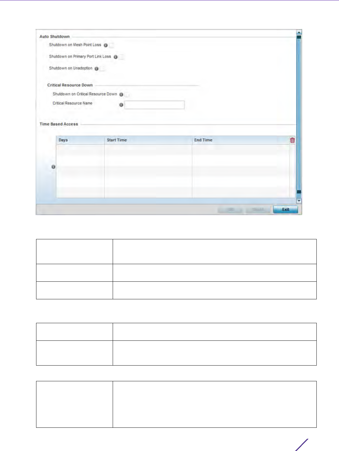
Wireless Configuration
Wireless Controller and Service Platform System Reference Guide 6 - 50
Figure 6-30 WLAN Policy Auto Shutdown screen
4 Refer to the Auto Shutdown field to set the WLANs shutdown criteria.
5 Set the following Critical Resource Down settings to determine whether a WLAN auto shutdown is enabled
when a defined critical resource goes offline:
6 To configure Time Based Access for this WLAN, click + Add Row and configure each of the following options.
Shutdown on Mesh Point
Loss
Select this option to automatically disable the WLAN when its
associated mesh point is unreachable. This setting is disabled by
default.
Shutdown on Primary
Port Link Loss
Select this option to automatically disable the WLAN when its primary
port link is unreachable. This setting is disabled by default.
Shutdown on
Unadoption
Select this option to automatically disable the WLAN when associated
Access Points are unadopted. This setting is disabled by default.
Shutdown on Critical
Resource Down
Enable this feature to bring the selected WLAN offline when a defined
critical resource goes offline. This setting is disabled by default.
Critical Resource Name When enabled, enter a 127 character maximum critical resource
name.This is the resource that must remain online to render the
selected WLAN online.
Days Use the drop-down menu to select a day of the week to apply this
access policy. Selecting All will apply the policy every day. Selecting
weekends will apply the policy on Saturdays and Sundays only.
Selecting weekdays will apply the policy on Monday, Tuesday,
Wednesday, Thursday and Friday only. Selecting individual days of the
week will apply the policy only on the selected day.
Wireless Configuration
Wireless Controller and Service Platform System Reference Guide 6 - 51
7Select OK when completed to update the auto shutdown settings. Select Reset to revert the screen back to its
last saved configuration.
6.2 Configuring WLAN QoS Policies
Wireless LAN Policy
QoS provides a data traffic prioritization scheme. QoS reduces congestion from excessive traffic. If there is enough
bandwidth for all users and applications (unlikely because excessive bandwidth comes at a very high cost), then
applying QoS has very little value. QoS provides policy enforcement for mission-critical applications and/or users
that have critical bandwidth requirements when bandwidth is shared by different users and applications.
QoS helps ensure each WLAN receives a fair share of the overall bandwidth, either equally or as per the proportion
configured. Packets directed towards clients are classified into categories such as Video, Voice and Data. Packets
within each category are processed based on the weights defined for each WLAN.
The Quality of Service screen displays a list of QoS policies available to WLANs. If none of the exiting QoS policies
supports an ideal QoS configuration for the intended data traffic of this WLAN, select the Add button to create
new policy. Select the radio button of an existing WLAN and select Ok to map the QoS policy to the WLAN
displayed in the banner of the screen.
Use the WLAN Quality of Service (QoS) Policy screen to add a new QoS policy or edit the attributes of an existing
policy.
Start Time This value sets the starting time the WLAN is activated. Use the
spinner controls to select the hour and minute, in a 12h time format.
Then use the radio button to choose AM or PM.
End Time This value sets the ending time of day(s) that the WLAN will be
disabled. Use the spinner controls to select the hour and minute, in a
12h time format. Then use the radio button to choose AM or PM.
NOTE: WLAN QoS configurations differ significantly from QoS policies configured
for radios. WLAN QoS configurations are designed to support the data requirements
of wireless clients, including the data types they support and their network
permissions. Radio QoS policies are specific to the transmit and receive
characteristics of the connected radio’s themselves, independent from the wireless
clients the Access Point radios supported.
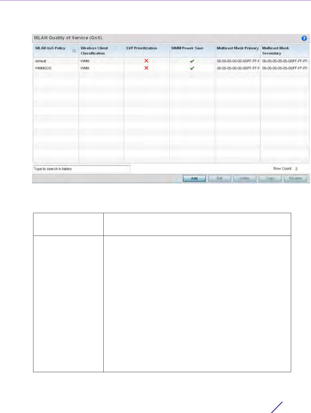
Wireless Configuration
Wireless Controller and Service Platform System Reference Guide 6 - 52
1Select Configuration > Wireless > WLAN QoS Policy to display existing QoS policies available to WLANs.
Figure 6-31 WLAN QoS Policy screen
2 Refer to the following read-only information on each listed QoS policy to determine whether an existing policy
can be used as is, an existing policy requires edit or a new policy requires creation:
WLAN QoS Policy Displays the name assigned to this WLAN QoS policy when it was
initially created. The assigned policy name cannot be modified as part
of the edit process.
Wireless Client
Classification
Lists each policy’s Wireless Client Classification as defined for this
WLAN's intended traffic. The Classification Categories are the different
WLAN-WMM options available to a radio. Classification types include:
WMM – Implies WiFi Multimedia QoS extensions are enabled on this
radio. This allows different traffic streams between the wireless client
and the Access Point to be prioritized according to the type of traffic
(voice, video etc). WMM classification is required to support the high
throughput data rates required of 802.11n device support.
Voice – Optimized for voice traffic. Implies all traffic on this WLAN is
prioritized as voice traffic on the radio.
Video – Optimized for video traffic. Implies all traffic on this WLAN is
prioritized as video traffic on the radio.
Normal – Optimized for best effort traffic. Implies all traffic on this
WLAN is prioritized as best effort traffic on the radio.
Low – Optimized for background traffic. Implies all traffic on this
WLAN is low priority on the radio.
Non-Unicast – Optimized for non-Unicast traffic. Implies all traffic on
this WLAN is designed for broadcast or multicast.
Wireless Configuration
Wireless Controller and Service Platform System Reference Guide 6 - 53
3 Either select the Add button to define a new WLAN QoS policy, or select an existing WLAN QoS policy and
select Edit to modify its existing configuration. Existing QoS policies can be selected and deleted as needed.
Optionally Copy a policy or Rename a WLAN QoS Policy as needed.
A Quality of Service (QoS) policy screen displays for the new or selected WLAN. The screen displays the WMM
tab by default, but additional tabs also display for WLAN and wireless client rate limit configurations. For more
information, refer to the following:
•Configuring a WLAN’s QoS WMM Settings
•Configuring Rate Limit Settings
6.2.1 Configuring a WLAN’s QoS WMM Settings
Using WMM, end-user satisfaction is maintained in a wider variety of environments and traffic conditions. WMM
makes it possible for both home networks and Enterprises to decide which data streams are most important and
assign them a higher traffic priority.
WMM’s prioritization capabilities are based on the four access categories. The higher the access category, the
higher the probability to transmit this kind of traffic over the WLAN. Access categories were designed to
correspond to 802.1d priorities to facilitate interoperability with QoS policy management mechanisms. WMM
enabled wireless controllers/Access Points coexist with legacy devices (not WMM-enabled).
Packets not assigned to a specific access category are categorized by default as having best effort priority.
Applications assign each data packet to a given access category packets are then added to one of four
independent transmit queues (one per access category - voice, video, best effort or background) in the client. The
SVP Prioritization A green check mark defines the policy as having Spectralink Voice
Prioritization (SVP) enabled to allow the wireless controller to identify
and prioritize traffic from Spectralink/Polycomm phones using the SVP
protocol. Phones using regular WMM and SIP are not impacted by SVP
prioritization. A red “X” defines the QoS policy as not supporting SVP
prioritization.
WMM Power Save Enables support for the WMM based power-save mechanism, also
known as Unscheduled Automatic Power Save Delivery (U-APSD). This
is primarily used by voice devices that are WMM capable. The default
setting is enabled.
Multicast Mask Primary Displays the primary multicast mask defined for each listed QoS policy.
Normally all multicast and broadcast packets are buffered until the
periodic DTIM interval (indicated in the 802.11 beacon frame), when
clients in power save mode wake to check for frames. However, for
certain applications and traffic types, the administrator may want the
frames transmitted immediately, without waiting for the DTIM interval.
By configuring a primary and secondary multicast mask, an
administrator can indicate which frames are transmitted immediately.
Setting masks is optional and only needed if there are traffic types
requiring special handling.
Multicast Mask
Secondary
Displays the secondary multicast mask defined for each listed QoS
policy.
NOTE: When using a wireless client classification other than WMM, only legacy rates
are supported on that WLAN.

Wireless Configuration
Wireless Controller and Service Platform System Reference Guide 6 - 54
client has an internal collision resolution mechanism to address collision among different queues, which selects the
frames with the highest priority to transmit.
The same mechanism deals with external collision, to determine which client(s) should be granted the opportunity
to transmit (TXOP). The collision resolution algorithm responsible for traffic prioritization is probabilistic and
depends on two timing parameters that vary for each access category.
• The minimum interframe space, or Arbitrary Inter-Frame Space Number (AIFSN)
• The contention window, sometimes referred to as the random backoff wait
Both values are smaller for high-priority traffic. The value of the contention window varies through time. Initially
the contention window is set to a value that depends on the AC. As frames with the highest AC tend to have the
lowest backoff values, they are more likely to get a TXOP.
After each collision the contention window is doubled until a maximum value (also dependent on the AC) is
reached. After successful transmission, the contention window is reset to its initial, AC dependant value. The AC
with the lowest backoff value gets the TXOP.
To configure a WMM configuration for a WLAN:
1Select
Configuration > Wireless > WLAN QoS Policy to display existing QoS Policies.
2 Select the Add button to create a new QoS policy or Edit to modify the properties of an existing WLAN QoS
policy.
The WMM tab displays by default.
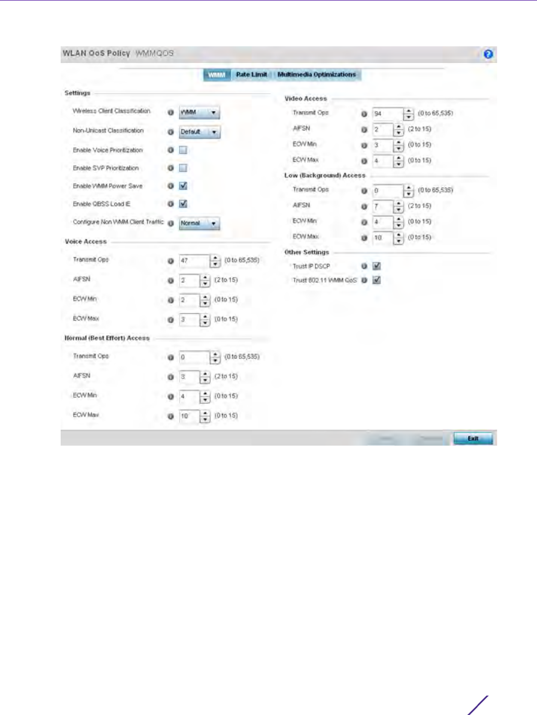
Wireless Configuration
Wireless Controller and Service Platform System Reference Guide 6 - 55
Figure 6-32 WLAN QoS Policy - WMM screen

Wireless Configuration
Wireless Controller and Service Platform System Reference Guide 6 - 56
3 Configure the following in respect to the WLAN’s intended WMM radio traffic and user requirements:
Wireless Client
Classification
Use the drop-down menu to select the Wireless Client Classification for
this WLAN's intended traffic type. The classification categories are the
different WLAN-WMM options available to the radio. Classification
types include:
WMM – Implies WiFi Multimedia QoS extensions are enabled on this
radio. This allows different traffic streams between the wireless client
and the Access Point to be prioritized according to the type of traffic
(voice, video etc). The WMM classification is required to support the
high throughput data rates required of 802.11n device support. WMM is
the default setting.
Voice – Optimized for voice traffic. Implies all traffic on this WLAN is
prioritized as voice traffic on the radio.
Video – Optimized for video traffic. Implies all traffic on this WLAN is
prioritized as video traffic on the radio.
Normal – Optimized for best effort traffic. Implies all traffic on this
WLAN is prioritized as best effort traffic on the radio.
Low – Optimized for background traffic. Implies all traffic on this
WLAN is low priority on the radio.
Non-Unicast
Classification
Use the drop-down menu to select the Non-Unicast Classification for
this WLAN's intended traffic. Non-unicast classification types include:
Voice – Optimized for voice traffic. Implies all traffic on this WLAN is
prioritized as voice traffic on the radio.
Video – Optimized for video traffic. Implies all traffic on this WLAN is
prioritized as video traffic on the radio.
Normal – Optimized for best effort traffic. Implies all traffic on this
WLAN is prioritized as best effort traffic on the radio.
Low – Optimized for background traffic. Implies all traffic on this
WLAN is low priority on the radio.
Enable Voice
Prioritization
Select this option if Voice traffic is prioritized on the WLAN. This gives
priority to voice and voice management packets supported only on
certain legacy VOIP phones. This feature is disabled by default.
Enable SVP
Prioritization
Enabling Spectralink Voice Prioritization (SVP) allows the identification
and prioritization of traffic from Spectralink/Polycomm phones. This
gives priority to voice on certain legacy VOIP phones. If the wireless
client classification is WMM, non WMM devices recognized as voice
devices have their traffic transmitted at voice priority. Devices are
classified as voice when they emit SIP, SCCP, or H323 traffic. Thus,
selecting this option has no effect on devices supporting WMM. This
feature is disabled by default.
Enable WMM Power
Save
Enables support for the WMM based power-save mechanism, also
known as Unscheduled Automatic Power Save Delivery (U-APSD). This
is primarily used by voice devices that are WMM capable. The default
setting is enabled.
Enable QBSS Load IE Check this option to enable a QoS Basis Service Set (QBSS)
information element (IE) in beacons and probe response packets
advertised by Access Points. The default value is enabled.

Wireless Configuration
Wireless Controller and Service Platform System Reference Guide 6 - 57
4 Set the following Voice Access settings for the WLAN’s QoS policy:
5 Set the following Normal (Best Effort) Access settings for the WLAN’s QoS policy:
Configure Non WMM
Client Traffic
Use the drop-down menu to select the Non-WMM client traffic
Classification.
Non-WMM classification types include:
Voice – Optimized for voice traffic. Implies all traffic on this WLAN is
prioritized as voice traffic on the radio.
Video – Optimized for video traffic. Implies all traffic on this WLAN is
prioritized as video traffic on the radio.
Normal – Optimized for best effort traffic. Implies all traffic on this
WLAN is prioritized as best effort traffic on the radio.
Low – Optimized for background traffic. Implies all traffic on this
WLAN is low priority on the radio.
Transmit Ops Use the slider to set the maximum device transmit duration after
obtaining a transmit opportunity. The default value is 47.
AIFSN Set the current Arbitrary Inter-frame Space Number (AIFSN) between
2-15. Higher-priority traffic voice categories should have lower AIFSNs
than lower-priority traffic categories. This will cause lower-priority
traffic to wait longer before attempting access. The default value is 2.
ECW Min The ECW Min is combined with the ECW Max to create the contention
value in the form of a numerical range. From this range, a random
number is selected for the back off mechanism. Lower values are used
for higher priority traffic. The available range is from 0-15. The default
value is 2.
ECW Max The ECW Max is combined with the ECW Min to create the contention
value in the form of a numerical range. From this range, a random
number is selected for the back off mechanism. Lower values are used
for higher priority traffic. The available range is from 0-15. The default
value is 3.
Transmit Ops Use the slider to set the maximum duration a device can transmit after
obtaining a transmit opportunity. The default value is 0.
AIFSN Set the current AIFSN between 2-15. Lower priority traffic categories
should have higher AIFSNs than higher priority traffic categories. This
will cause lower priority traffic to wait longer before attempting
access. The default value is 3.
ECW Min The ECW Min is combined with the ECW Max to create the contention
value in the form of a numerical range. From this range, a random
number is selected for the back off mechanism. Higher values are used
for lower priority traffic (like Normal). The available range is from 0-15.
The default value is 4.
ECW Max The ECW Max is combined with the ECW Min to create the contention
value in the form of a numerical range. From this range, a random
number is selected for the back off mechanism. Higher values are used
for lower priority traffic (like Normal). The available range is from 0-15.
The default value is 10.

Wireless Configuration
Wireless Controller and Service Platform System Reference Guide 6 - 58
6 Set the following Video Access settings for the WLAN’s QoS policy:
7 Set the following Low (Background) Access settings for the WLAN’s QoS policy:
8 Set the following Other Settings for the WLAN’s QoS policy:
9Select
OK when completed to update this WLAN’s QoS settings. Select Reset to revert the screen back to its
last saved configuration.
6.2.2 Configuring Rate Limit Settings
Excessive traffic can cause performance issues or bring down the network entirely. Excessive traffic can be caused
by numerous sources including network loops, faulty devices or malicious software such as a worm or virus that
Transmit Ops Use the slider to set the maximum duration a device can transmit after
obtaining a transmit opportunity. The default values is 94.
AIFSN Set the current Arbitrary Inter-frame Space Number (AIFSN) between
2-15. Higher-priority traffic video categories should have lower AIFSNs
than lower-priority traffic categories. This will cause lower-priority
traffic to wait longer before attempting access. The default value is 2.
ECW Min The ECW Min is combined with the ECW Max to create the contention
value in the form of a numerical range. From this range, a random
number is selected for the back off mechanism. Lower values are used
for higher priority traffic (like video). The available range is from 0-15.
The default value is 3.
ECW Max The ECW Max is combined with the ECW Min to create the contention
value in the form of a numerical range. From this range, a random
number is selected for the back off mechanism. Lower values are used
for higher priority traffic (like video). The available range is from 0-15.
The default value is 4.
Transmit Ops Use the slider to set the maximum duration a device can transmit after
obtaining a transmit opportunity. For higher-priority traffic categories,
this value should be set to a low number. The default value is 0.
AIFSN Set the current AIFSN between 2-15. Lower priority traffic categories
should have higher AIFSNs than higher priority traffic categories. This
will cause lower priority traffic to wait longer before attempting
access. The default value is 7.
ECW Min The ECW Min is combined with the ECW Max to create the contention
value in the form of a numerical range. From this range, a random
number is selected for the back off mechanism. Higher values are used
for lower priority traffic (like Low). The available range is from 0-15.
The default value is 4.
ECW Max The ECW Max is combined with the ECW Min to create the contention
value in the form of a numerical range. From this range, a random
number is selected for the back off mechanism. Higher values are used
for lower priority traffic (like Low). The available range is from 0-15.
The default value is 10.
Trust IP DSCP Select this option to trust IP DSCP values for WLANs. The default
value is enabled.
Trust 802.11 WMM QoS Select this option to trust 802.11 WMM QoS values for WLANs. The
default value enabled.

Wireless Configuration
Wireless Controller and Service Platform System Reference Guide 6 - 59
has infected on one or more devices. Rate limiting reduces the maximum rate sent or received from the wireless
network (and WLAN) per wireless client. It prevents any single user from overwhelming the wireless network. It
can also provide differential service for service providers. The uplink and downlink rate limits are usually configured
on a RADIUS server using vendor specific attributes. Rate limits are extracted from the RADIUS server’s response.
When such attributes are not present, the settings defined on the controller, service platform or Access Point are
applied. An administrator can set separate QoS rate limit configurations for data transmitted from the network
(upstream) and data transmitted from a WLAN’s wireless clients back to associated radios (downstream).
Before defining rate limit thresholds for WLAN upstream and downstream traffic, define the normal number of
ARP, broadcast, multicast and unknown unicast packets that typically transmit and receive from each supported
WMM access category. If thresholds are defined too low, normal network traffic (required by end-user devices) will
be dropped resulting in intermittent outages and performance problems.
Connected wireless clients can also have QoS rate limit settings defined in both the upstream and downstream
direction.
To configure a QoS rate limit configuration for a WLAN:
1Select
Configuration > Wireless > WLAN QoS Policy to display existing QoS policies available to WLANs.
2 Either select the Add button to define a new WLAN QoS policy, or select an existing WLAN QoS policy and
select Edit to modify its existing configuration.
3 Select the Rate Limit tab.
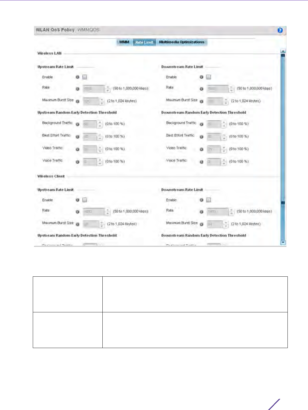
Wireless Configuration
Wireless Controller and Service Platform System Reference Guide 6 - 60
Figure 6-33 QoS Policy WLAN Rate Limit screen
4 Configure the following parameters in respect to the intended WLAN Upstream Rate Limit, or traffic from the
controller or service platform to associated Access Point radios and connected wireless clients:
Enable Select the Enable check box to enable rate limiting for data
transmitted from the controller or service platform to associated
Access Point radios and connected wireless clients. Enabling this
option does not invoke rate limiting for data traffic in the downstream
direction. This feature is disabled by default.
Rate Define an upstream rate limit between 50 - 1,000,000 kbps. This limit
constitutes a threshold for the maximum the number of packets
transmitted or received over the WLAN (from all access categories).
Traffic that exceeds the defined rate is dropped and a log message is
generated. The default setting is 5000 kbps.

Wireless Configuration
Wireless Controller and Service Platform System Reference Guide 6 - 61
5 Set the following WLAN Upstream Random Early Detection Threshold settings for each access category. An
early random drop is done when a traffic stream falls below the set threshold.
6 Configure the following parameters in respect to the intended WLAN Downstream Rate Limit, or traffic from
wireless clients to associated Access Point radios and the controller or service platform:
Maximum Burst Size Set a maximum burst size between 2 - 1024 kbytes. The smaller the
burst, the less likely the upstream packet transmission will result in
congestion for the WLAN’s client destinations. By trending the typical
number of ARP, broadcast, multicast and unknown unicast packets
over a period of time, the average rate for each access category can
be obtained. Once a baseline is obtained, administrators should add a
10% margin (minimally) to allow for traffic bursts. The default burst
size is 320 kbytes.
Background Traffic Set a percentage value for background traffic in the upstream
direction. This is a percentage of the maximum burst size for low
priority traffic. Background traffic exceeding the defined threshold is
dropped and a log message is generated. Background traffic
consumes the least bandwidth of any access category, so this value
can be set to a lower value once a general upstream rate is known by
the network administrator (using a time trend analysis). The default
threshold is 50%.
Best Effort Traffic Set a percentage value for best effort traffic in the upstream direction.
This is a percentage of the maximum burst size for normal priority
traffic. Best effort traffic exceeding the defined threshold is dropped
and a log message is generated. Best effort traffic consumes little
bandwidth, so this value can be set to a lower value once a general
upstream rate is known by the network administrator (using a time
trend analysis). The default threshold is 50%.
Video Traffic Set a percentage value for video traffic in the upstream direction. This
is a percentage of the maximum burst size for video traffic. Video
traffic exceeding the defined threshold is dropped and a log message
is generated. Video traffic consumes significant bandwidth, so this
value can be set to a higher value once a general upstream rate is
known by the network administrator (using a time trend analysis). The
default threshold is 25%.
Voice Traffic Set a percentage value for voice traffic in the upstream direction. This
is a percentage of the maximum burst size for voice traffic. Voice
traffic exceeding the defined threshold is dropped and a log message
is generated. Voice applications consume significant bandwidth, so this
value can be set to a higher value once a general upstream rate is
known by the network administrator (using a time trend analysis). The
default threshold is 0%.
Enable Select the Enable radio button to enable rate limiting for data
transmitted from the controller or service platform to its associated
Access Point radios and connected wireless clients. Enabling this
option does not invoke rate limiting for data traffic in the upstream
direction. This feature is disabled by default.

Wireless Configuration
Wireless Controller and Service Platform System Reference Guide 6 - 62
7 Set the following WLAN Downstream Random Early Detection Threshold settings for each access category. An
early random drop is done when the amount of tokens for a traffic stream falls below the set threshold.
8 Configure the following parameters in respect to the intended Wireless Client Upstream Rate Limit:
Rate Define an upstream rate limit between 50 - 1,000,000 kbps. This limit
constitutes a threshold for the maximum the number of packets
transmitted or received over the WLAN (from all access categories).
Traffic that exceeds the defined rate is dropped and a log message is
generated. The default setting is 5000 kbps.
Maximum Burst Size Set a maximum burst size between 2 - 1024 kbytes. The smaller the
burst, the less likely the downstream packet transmission will result in
congestion for the WLAN’s client destinations. By trending the typical
number of ARP, broadcast, multicast and unknown unicast packets
over a period of time, the average rate for each access category can be
obtained. Once a baseline is obtained, administrators should add a 10%
margin (minimally) to allow for traffic bursts. The default burst size is
320 kbytes.
Background Traffic Set a percentage value for background traffic in the downstream
direction. This is a percentage of the maximum burst size for low
priority traffic. Background traffic exceeding the defined threshold is
dropped and a log message is generated. Background traffic
consumes the least bandwidth of any access category, so this value
can be set to a lower value once a general downstream rate is known
by the network administrator (using a time trend analysis). The default
threshold is 50%.
Best Effort Traffic Set a percentage value for best effort traffic in the downstream
direction. This is a percentage of the maximum burst size for normal
traffic. Best effort traffic exceeding the defined threshold is dropped
and a log message is generated. Best effort traffic consumes little
bandwidth, so this value can be set to a lower value once a general
downstream rate is known by the network administrator (using a time
trend analysis). The default threshold is 50%.
Video Traffic Set a percentage value for video traffic in the downstream direction.
This is a percentage of the maximum burst size for video traffic. Video
traffic exceeding the defined threshold is dropped and a log message
is generated. Video traffic consumes significant bandwidth, so this
value can be set to a higher value once a general downstream rate is
known by the network administrator (using a time trend analysis). The
default threshold is 25%.
Voice Traffic Set a percentage value for voice traffic in the downstream direction.
This is a percentage of the maximum burst size for voice traffic. Voice
traffic exceeding the defined threshold is dropped and a log message
is generated. Voice applications consume significant bandwidth, so this
value can be set to a higher value once a general upstream rate is
known by the network administrator (using a time trend analysis). The
default threshold is 0%. 0% means no early random drops will occur.
Enable Select the Enable radio button to enable rate limiting for data
transmitted from the client to its associated Access Point radio and
connected wireless controller. Enabling this option does not invoke
client rate limiting for data traffic in the downstream direction. This
feature is disabled by default.

Wireless Configuration
Wireless Controller and Service Platform System Reference Guide 6 - 63
9 Set the following Wireless Client Upstream Random Early Detection Threshold settings for each access
category:
10 Configure the following parameters in respect to the intended Wireless Client Downstream Rate Limit (traffic
from a controller or service platform to associated Access Point radios and the wireless client):
11 Set the following Wireless Clients Downstream Random Early Detection Threshold settings:
Rate Define an upstream rate limit between 50 - 1,000,000 kbps. This limit
constitutes a threshold for the maximum the number of packets
transmitted or received (from all access categories). Traffic that
exceeds the defined rate is dropped by the client and a log message is
generated. The default rate is 1,000 kbps.
Maximum Burst Size Set a maximum burst size between 2 - 1024 kbytes. The smaller the
burst, the less likely the upstream packet transmission will result in
congestion for the wireless client. The default burst size is 64 kbytes.
Background Traffic Set a percentage value for background traffic in the upstream
direction. This is a percentage of the maximum burst size for low
priority traffic. Background traffic exceeding the defined threshold is
dropped by the client and a log message is generated. The default
threshold is 50%.
Best Effort Traffic Set a percentage for best effort traffic in the upstream direction. This
is a percentage of the maximum burst size for normal traffic. Best
effort traffic exceeding the defined threshold is dropped by the client
and a log message is generated. The default threshold is 50%.
Video Traffic Set a percentage value for video traffic in the upstream direction. This
is a percentage of the maximum burst size for video traffic. Video
traffic exceeding the defined threshold is dropped by the client and a
log message is generated. The default threshold is 25%.
Voice Traffic Set a percentage value for voice traffic in the downstream direction.
This is a percentage of the maximum burst size for voice traffic. Voice
traffic exceeding the defined threshold is dropped by the client and a
log message is generated. The default threshold is 0%.0% implies no
early random drops occur.
Enable Select the Enable radio button to enable rate limiting for data
transmitted from connected wireless clients to the controller or service
platform. Enabling this option does not invoke rate limiting for data
traffic in the upstream direction. This feature is disabled by default.
Rate Define a downstream rate limit between 50 - 1,000,000 kbps.This limit
constitutes a threshold for the maximum the number of packets
transmitted or received by the client. Traffic that exceeds the defined
rate is dropped and a log message is generated. The default rate is
1,000 kbytes.
Maximum Burst Size Set a maximum burst size between 2 - 64 kbytes. The smaller the
burst, the less likely the downstream packet transmission will result in
congestion for the wireless client. The default burst size is 64 kbytes.
Background Traffic Set a percentage value for background traffic in the downstream
direction. This is a percentage of the maximum burst size for low
priority traffic. Background traffic exceeding the defined threshold is
dropped by the client and a log message is generated. The default is
50%.

Wireless Configuration
Wireless Controller and Service Platform System Reference Guide 6 - 64
12 Select OK to update this WLAN’s QoS rate limit settings. Select Reset to revert to the last saved configuration.
6.2.3 Configuring Multimedia Optimization Settings
Multimedia optimizations customize the size and speed of multimedia content (voice, video etc.) to deliver WLAN
traffic strategically to the WLAN's managed clients and their defined QoS requirements.
To configure multimedia optimizations for a controller, service platform or Access Point managed WLAN:
1Select
Configuration > Wireless > WLAN QoS Policy to display existing QoS policies available to WLANs.
2 Either select the Add button to define a new WLAN QoS policy, or select an existing WLAN QoS policy and
select Edit to modify its existing configuration.
3 Select the Multimedia Optimizations tab.
Best Effort Traffic Set a percentage value for best effort traffic in the downstream
direction. This is a percentage of the maximum burst size for normal
traffic. Best effort traffic exceeding the defined threshold is dropped by
the client and a log message is generated. The default is 50%.
Video Traffic Set a percentage value for video traffic in the downstream direction.
This is a percentage of the maximum burst size for video traffic. Video
traffic exceeding the defined threshold is dropped by the client and a
log message is generated. The default is 25%.
Voice Traffic Set a percentage value for voice traffic in the downstream direction.
This is a percentage of the maximum burst size for voice traffic. Voice
traffic exceeding the defined threshold is dropped by the client and a
log message is generated. The default threshold is 0%.0% means no
early random drops occur.
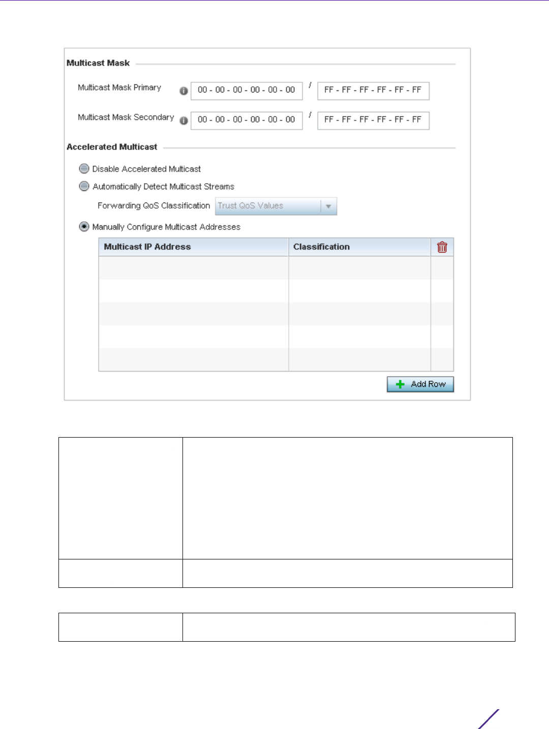
Wireless Configuration
Wireless Controller and Service Platform System Reference Guide 6 - 65
Figure 6-34 QoS Policy WLAN Multimedia Optimizations screen
4 Configure the following parameters in respect to the intended Multicast Mask:
5 Set the following Accelerated Multicast settings:
Multicast Mask Primary Configure the primary multicast mask defined for each listed QoS
policy. Normally all multicast and broadcast packets are buffered until
the periodic DTIM interval (indicated in the 802.11 beacon frame), when
clients in power save mode wake to check for frames. However, for
certain applications and traffic types, an administrator may want the
frames transmitted immediately, without waiting for the DTIM interval.
By configuring a primary and secondary multicast mask, an
administrator can indicate which frames are transmitted immediately.
Setting masks is optional and only needed if there are traffic types
requiring special handling.
Multicast Mask
Secondary
Set a secondary multicast mask for the WLAN QoS policy in case the
primary becomes unavailable.
Disable Multicast
Streaming
Select this option to disable all Multicast Streaming on the WLAN.

Wireless Configuration
Wireless Controller and Service Platform System Reference Guide 6 - 66
6Select OK when completed to update this WLAN's Multimedia Optimizations settings. Select Reset to revert the
screen back to its last saved configuration.
6.2.4 WLAN QoS Deployment Considerations
Before defining a QoS configuration on a WLAN, refer to the following deployment guidelines to ensure the
configuration is optimally effective:
• WLAN QoS configurations differ significantly from QoS policies configured for wireless controller associated
Access Point radios. WLAN QoS configurations are designed to support the data requirements of wireless
clients, including the data types they support and their network permissions. Radio QoS policies are specific to
the transmit and receive characteristics of the connected radio’s themselves, independent from the wireless
clients these Access Point radios support.
• Enabling WMM support on a WLAN only advertises WMM capability to wireless clients. The wireless clients
must be also able to support WMM and use the parameters correctly while accessing the wireless network to
truly benefit.
• Rate limiting is disabled by default on all WLANs. To enable rate limiting, a threshold must be defined for
WLAN.
• Before enabling rate limiting on a WLAN, a baseline for each traffic type should be performed. Once a baseline
has been determined, a minimum 10% margin should be added to allow for traffic bursts.
• The bandwidth required for real-time applications such as voice and video are very fairly easy to calculate as
the bandwidth requirements are consistent and can be realistically trended over time. Applications such as
Web, database and Email are harder to estimate, since bandwidth usage varies depending on how the
applications are utilized.
6.3 Radio QoS Policy
Without a dedicated QoS policy, a wireless network operates on a best-effort delivery basis, meaning all traffic has
equal priority and an equal chance of being delivered in a timely manner. When congestion occurs, all traffic has
an equal chance of being dropped!
When configuring a QoS policy for a radio, select specific network traffic, prioritize it, and use congestion-
management and congestion-avoidance techniques to provide deployment customizations best suited to each
QoS policy’s intended wireless client base.
Wireless devices, associated Access Point radios and connected clients support several Quality of Service (QoS)
techniques enabling real-time applications (such as voice and video) to co-exist simultaneously with lower priority
background applications (such as Web, E-mail and file transfers). A well designed QoS policy should:
Automatically Detect
Multicast Streams
Select this option to have multicast packets converted to unicast to
provide better overall airtime utilization and performance. The
administrator can either have the system automatically detect multicast
streams and convert all detected multicast streams to unicast, or
specify which multicast streams are converted to unicast. When the
stream is converted and queued for transmission, there are a number
of classification mechanisms that can be applied to the stream and the
administrator can select what type of classification they wan.
Manually Configure
Multicast Adddresses
Select this option and specify a list of multicast addresses and
classifications. Packets are accelerated when the destination addresses
matches.

Wireless Configuration
Wireless Controller and Service Platform System Reference Guide 6 - 67
• Classify and mark data traffic to accurately prioritize and segregate it (by access category) throughout the
network.
• Minimize the network delay and jitter for latency sensitive traffic.
• Ensure higher priority traffic has a better likelihood of delivery in the event of network congestion.
• Prevent the ineffective utilization of Access Points degrading session quality by configuring admission control
mechanisms within each radio QoS policy
Wireless clients supporting low and high priority traffic contend with one another for access and data resources.
The IEEE 802.11e amendment has defined Enhanced Distributed Channel Access (EDCA) mechanisms stating high
priority traffic can access the network sooner then lower priority traffic. The EDCA defines four traffic classes (or
access categories); voice (highest), video (next highest), best effort and background (lowest).The EDCA has
defined a time interval for each traffic class, known as the Transmit Opportunity (TXOP). The TXOP prevents traffic
of a higher priority from completely dominating the wireless medium, thus ensuring lower priority traffic is still
supported by controller or service platform associated Access Points and their connected radios.
IEEE 802.11e includes an advanced power saving technique called Unscheduled Automatic Power Save Delivery (U-
APSD) that provides a mechanism for wireless clients to retrieve packets buffered by an Access Point. U-APSD
reduces the amount of signaling frames sent from a client to retrieve buffered data from an Access Point. U-APSD
also allows Access Points to deliver buffered data frames as bursts, without backing-off between data frames.
These improvements are useful for voice clients, as they provide improved battery life and call quality.
The Wi-Fi alliance has created Wireless Multimedia (WMM) and WMM Power Save (WMM-PS) certification
programs to ensure interoperability between 802.11e WLAN infrastructure implementations and wireless clients. A
WiNG wireless network supports both WMM and WMM-Power Save techniques. WMM and WMM-PS (U-APSD) are
enabled by default in each WLAN profile.
Enabling WMM support on a WLAN just advertises the WLAN’s WMM capability and radio configuration to
wireless clients. The wireless clients must be also able to support WMM and use the values correctly while
accessing the WLAN.
WMM includes advanced parameters (CWMin, CWMax, AIFSN and TXOP) specifying back-off duration and inter-
frame spacing when accessing the network. These parameters are relevant to both connected Access Point radios
and their wireless clients. Parameters impacting Access Point transmissions to their clients are controlled using per
radio WMM settings, while parameters used by wireless clients are controlled by a WLAN’s WMM settings.
WiNG wireless devices include a Session Initiation Protocol (SIP), Skinny Call Control Protocol (SCCP) and
Application Layer Gateway (ALGs) enabling devices to identify voice streams and dynamically set voice call
bandwidth. Controllers and service platforms use the data to provide prioritization and admission control to these
devices without requiring TSPEC or WMM client support.
WiNG wireless devices support static QoS mechanisms per WLAN to provide prioritization of WLAN traffic when
legacy (non WMM) clients are deployed. When enabled on a WLAN, traffic forwarded to a client is prioritized and
forwarded based on the WLAN’s WMM access control setting.
NOTE: Statically setting a WLAN WMM access category value only prioritizes traffic
from the to the client, not from the client.
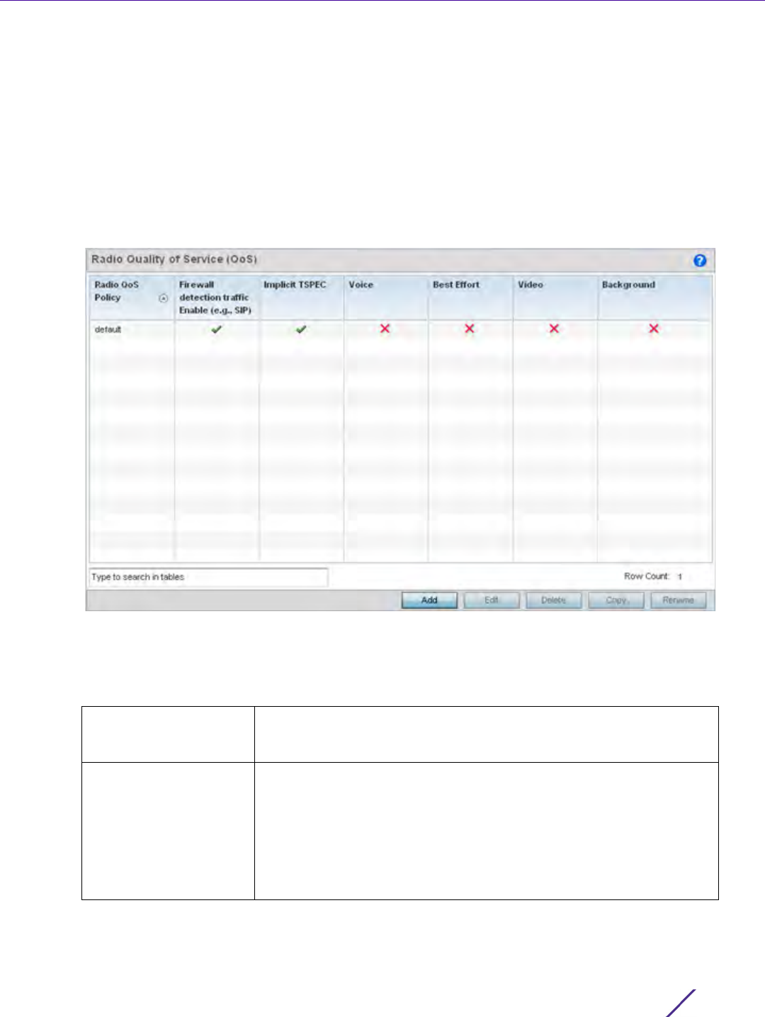
Wireless Configuration
Wireless Controller and Service Platform System Reference Guide 6 - 68
Rate limits can be applied to WLANs using groups defined locally or externally from a RADIUS server using Vendor
Specific Attributes (VSAs). Rate limits can be applied to authenticating users using 802.1X, captive portal
authentication and MAC authentication.
6.3.1 Configuring Radio QoS Policies
Radio QoS Policy
To configure a radio’s QoS policy:
1Select
Configuration > Wireless > Radio QoS Policy to display existing Radio QoS policies.
Figure 6-35 Radio QoS Policy screen
The Radio QoS Policy screen lists those radio QoS policies created thus far. Any of these policies can be
selected and applied.
2 Refer to the following information listed for each existing Radio QoS policy:
Radio QoS Policy Displays the name of each Radio QoS policy. This is the name set for
each listed policy when it was created and cannot be modified as part
of the policy edit process.
Firewall detection traffic
Enable (e.g., SIP)
A green check mark defines the policy as applying radio QoS settings
to traffic detected by the Firewall. A red “X” defines the policy as
having Firewall detection disabled. When enabled, the Firewall
simulates the reception of frames for voice traffic when the voice traffic
was originated via SIP or SCCP control traffic. If a client exceeds
configured values, the call is stopped and/or received voice frames are
forwarded at the next non admission controlled traffic class priority.
This applies to clients that do not send TSPEC frames only.
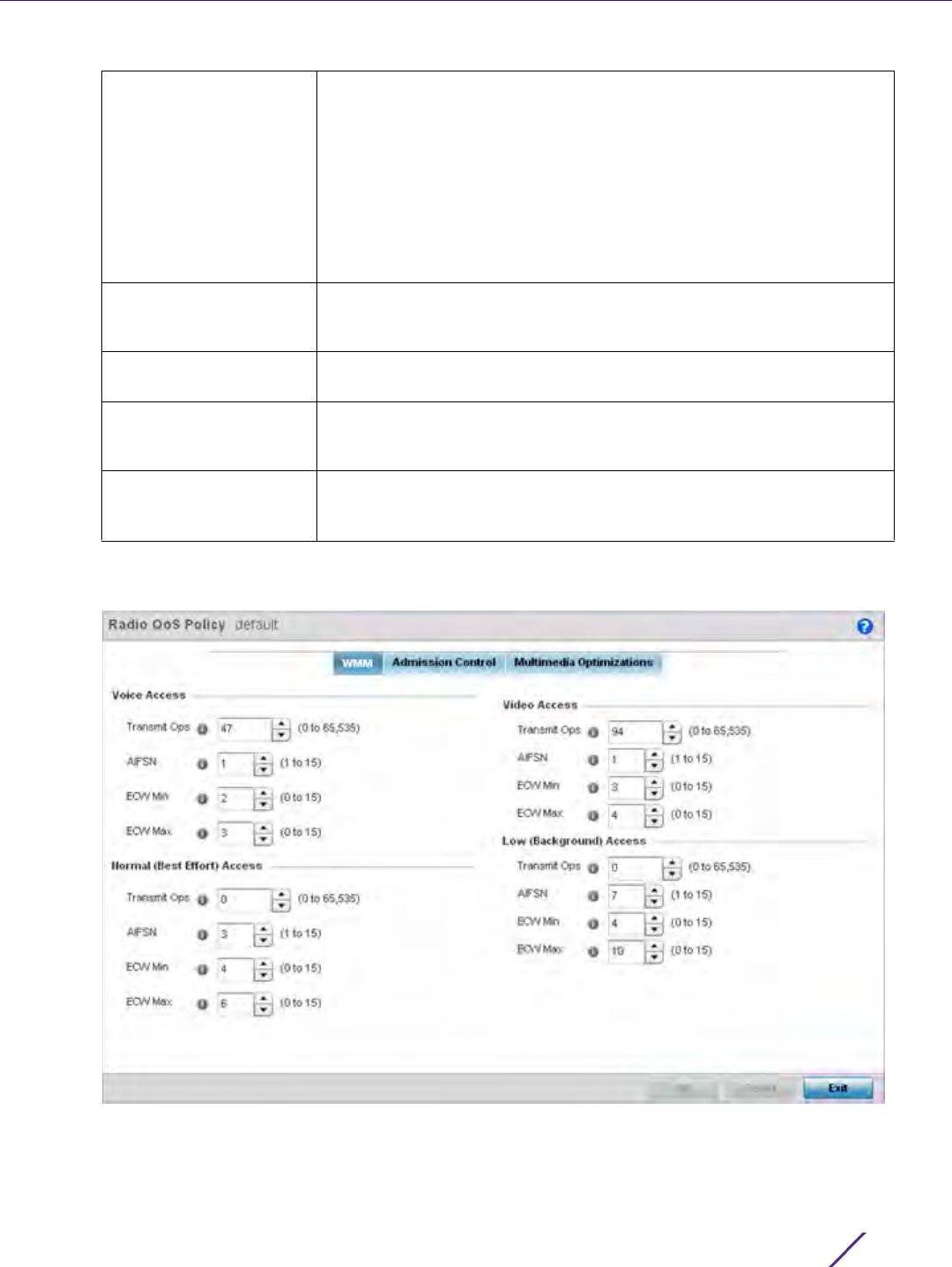
Wireless Configuration
Wireless Controller and Service Platform System Reference Guide 6 - 69
3 Either select Add to create a new radio QoS policy, or select one of the existing policies listed and select the
Edit button to modify its configuration. Optionally Copy or Rename QoS policies as needed.
Figure 6-36 Radio QoS Policy WMM screen
The Radio QoS Policy screen displays the WMM tab by default. Use the WMM tab to define the access category
configuration (CWMin, CWMax, AIFSN and TXOP values) in respect to the type of wireless data planned for this
new or updated WLAN radio QoS policy.
Implicit TSPEC A green check mark defines the policy as requiring wireless clients to
send their traffic specifications to a controller or service platform
managed Access Point before they can transmit or receive data. If
enabled, this setting applies to just this radio’s QoS policy. When
enabled, the Access Point simulates the reception of frames for any
traffic class by looking at the amount of traffic the client is receiving
and sending. If the client sends more traffic than has been configured
for an admission controlled traffic class, the traffic is forwarded at the
priority of the next non admission controlled traffic class. This applies
to clients that do not send TSPEC frames only.
Voice A green check mark indicates that Voice prioritization QoS is enabled
on the radio. A red X indicates Voice prioritization QoS is disabled on
the radio.
Best Effort A green check mark indicates that Best Effort QoS is enabled on the
radio. A red X indicates Best Effort QoS is disabled on the radio.
Video A green check mark indicates that Video prioritization QoS is enabled
on the radio. A red X indicates Video prioritization QoS is disabled on
the radio.
Background A green check mark indicates that Background prioritization QoS is
enabled on the radio. A red X indicates Background prioritization QoS
is disabled on the radio.

Wireless Configuration
Wireless Controller and Service Platform System Reference Guide 6 - 70
4 Set the following Voice Access settings for the Radio QoS policy:
5 Set the following Normal (Best Effort) Access settings for the radio QoS policy:
6 Set the following Video Access settings for the Radio QoS policy:
Transmit Ops Use the slider to set the maximum duration a device can transmit after
obtaining a transmit opportunity. When resources are shared between
a Voice over IP (VoIP) call and a low priority file transfer, bandwidth is
normally exploited by the file transfer, thus reducing call quality or
even causing the call to disconnect. With voice QoS, a VoIP call (a real-
time session), receives priority, maintaining a high level of voice quality.
For higher-priority traffic categories (like voice), the Transmit Ops
value should be set to a low number. The default value is 47.
AIFSN Set the current AIFSN between 1-15. Higher-priority traffic voice
categories should have lower AIFSNs than lower-priority traffic
categories. This will cause lower-priority traffic to wait longer before
attempting access. The default value is 1.
ECW Min The ECW Min is combined with the ECW Max to create a contention
value in the form of a numerical range. From this range, a random
number is selected for the back off mechanism. Lower values are used
for higher priority traffic. The available range is from 0-15. The default
value is 2.
ECW Max The ECW Max is combined with the ECW Min to create a contention
value in the form of a numerical range. From this range, a random
number is selected for the back off mechanism. Lower values are used
for higher priority traffic. The available range is from 0-15. The default
value is 3.
Transmit Ops Use the slider to set the maximum duration a device can transmit after
obtaining a transmit opportunity. For higher-priority traffic categories,
this value should be set to a low number. The default value is 0.
AIFSN Set the current AIFSN between1-15. Lower priority traffic categories
should have higher AIFSNs than higher priority traffic categories. This
will cause lower priority traffic to wait longer before attempting
access. The default value is 3.
ECW Min The ECW Min is combined with the ECW Max to create a contention
value in the form of a numerical range. From this range, a random
number is selected for the back off mechanism. Higher values are used
for lower priority traffic (like Normal). The available range is from 0-15.
The default value is 4.
ECW Max The ECW Max is combined with the ECW Min to create a contention
value in the form of a numerical range. From this range, a random
number is selected for the back off mechanism. Higher values are used
for lower priority traffic (like Normal). The available range is from 0-15.
The default value is 6.
Transmit Ops Use the spinner control to set the maximum duration a radio can
transmit after obtaining a transmit opportunity. For higher-priority
traffic categories (like video), this value should be set to a low number.
The default value is 94.

Wireless Configuration
Wireless Controller and Service Platform System Reference Guide 6 - 71
7 Set the following Low (Background) Access settings for the radio QoS policy:
8Select
OK when completed to update the radio QoS settings for this policy. Select Reset to revert the WMM
screen back to its last saved configuration.
9 Select the Admission Control tab to configure an admission control configuration for selected radio QoS policy.
Admission control requires clients send their traffic specifications (TSPEC) to a controller or service platform
managed Access Point before they can transmit or receive data.
The name of the Radio QoS policy for which the admission control settings apply displays in the banner of the
QoS Policy screen.
AIFSN Set the current AIFSN between 1-15. Higher-priority traffic categories
should have lower AIFSNs than lower-priority traffic categories. This
will cause lower-priority traffic to wait longer before attempting
access. The default value is 1.
ECW Min The ECW Min is combined with the ECW Max to create a contention
value in the form of a numerical range. From this range, a random
number is selected for the back off mechanism. Lower values are used
for higher priority traffic (like video). The available range is from 0-15.
The default value is 3.
ECW Max The ECW Max is combined with the ECW Min to create a contention
value in the form of a numerical range. From this range, a random
number is selected for the back off mechanism. Lower values are used
for higher priority traffic (like video). The available range is from 0-15.
The default value is 4.
Transmit Ops Use the slider to set the maximum duration a device can transmit after
obtaining a transmit opportunity. For higher-priority traffic categories,
this value should be set to a low number. The default value is 0.
AIFSN Set the current AIFSN between 1-15. Lower priority traffic categories
should have higher AIFSNs than higher priority traffic categories. This
will cause lower priority traffic to wait longer before attempting
access. The default value is 7.
ECW Min The ECW Min is combined with the ECW Max to create a contention
value in the form of a numerical range. From this range, a random
number is selected for the back off mechanism. Higher values are used
for lower priority traffic (like Low). The available range is from 0-15.
The default value is 4.
ECW Max The ECW Max is combined with the ECW Min to create a contention
value in the form of a numerical range. From this range, a random
number is selected for the back off mechanism. Lower values are used
for higher priority traffic (like video). The available range is from 0-15.
The default value is 10.
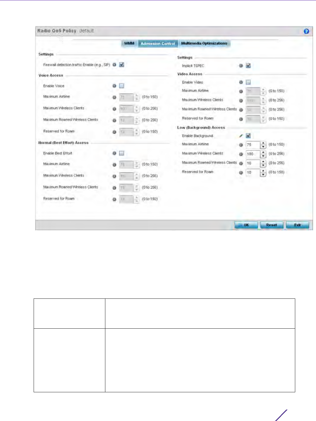
Wireless Configuration
Wireless Controller and Service Platform System Reference Guide 6 - 72
Figure 6-37 Radio QoS Policy Admission Control screen
10 Select the Firewall detection traffic Enable (e.g, SIP) check box to force admission control to traffic whose
access category is detected by the firewall. This feature is enabled by default.
11 Select the Implicit TSPEC check box to require wireless clients to send their traffic specifications to a controller
or service platform managed Access Point before they can transmit or receive data. If enabled, this setting
applies to just this radio’s QoS policy. This feature is enabled by default.
12 Set the following Voice Access admission control settings for this radio QoS policy:
Enable Voice Select the check box to enable admission control for this policy’s voice
traffic. Only voice traffic admission control is enabled, not any of the
other access categories (each access category must be separately
enabled and configured).
Maximum Airtime Set the maximum airtime (in the form of a percentage of the radio’s
bandwidth) allotted to admission control for voice supported client
traffic. The available percentage range is from 0-150%, with 150% being
available to account for over-subscription. This value ensures the
radio’s bandwidth is available for high bandwidth voice traffic (if
anticipated on the wireless medium) or other access category traffic if
voice support is not prioritized. Voice traffic requires longer radio
airtime to process, so set a longer airtime value if this radio QoS policy
is intended to support voice. The default value is 75%.

Wireless Configuration
Wireless Controller and Service Platform System Reference Guide 6 - 73
13 Set the following Normal (Best Effort) Access admission control settings for this radio QoS policy
14 Set the following Video Access admission control settings for this radio QoS policy:
Maximum Wireless
Clients
Set the number of voice supported wireless clients allowed to exist
(and consume bandwidth) within the radio’s QoS policy. Select from
an available range of 0-256 clients. Consider setting this value
proportionally to the number of other QoS policies supporting the
voice access category, as wireless clients supporting voice use a
greater proportion of resources than lower bandwidth traffic (like low
and best effort categories). The default value is 100 clients.
Maximum Roamed
Wireless Clients
Set the number of voice supported wireless clients allowed to roam to
a different radio. Select from a range of 0-256 clients. The default
value is 10 roamed clients.
Reserved for Roam Set the roam utilization (in the form of a percentage of the radio’s
bandwidth) allotted to admission control for voice supported clients
who have roamed to a different radio. The available percentage range
is from 0-150%, with 150% available to account for over-subscription.
The default value is 10%.
Enable Best Effort Select the check box to enable admission control for this policy’s video
traffic. Only normal background traffic admission control is enabled,
not any of the other access categories (each access category must be
separately enabled and configured). This feature is disabled by default.
Maximum Airtime Set the maximum airtime (in the form of a percentage of the radio’s
bandwidth) allotted to admission control for normal background client
traffic. The available percentage range is from 0-150%, with 150%
being available to account for over-subscription. This value helps
ensure the radio’s bandwidth is available for lower bandwidth normal
traffic (if anticipated to proliferate the wireless medium). Normal
background traffic only needs a short radio airtime to process, so set
an intermediate airtime value if this radio QoS policy is reserved for
background data support. The default value is 75%.
Maximum Wireless
Clients
Set the number of wireless clients supporting background traffic
allowed to exist (and consume bandwidth) within the radio’s QoS
policy. Select from an available range of 0-256 clients. The default
value is 100 clients.
Maximum Roamed
Wireless Clients
Set the number of voice supported wireless clients allowed to roam to
a different radio. Select from a range of 0-256 clients. The default
value is 10 roamed clients.
Reserved for Roam Set the roam utilization (in the form of a percentage of the radio’s
bandwidth) allotted to admission control for normal background
supported clients who have roamed to a different radio. The available
percentage range is from 0-150%, with 150% available to account for
over-subscription. The default value is 10%.
Enable Video Select the check box to enable admission control for this policy’s video
traffic. Only video traffic admission control is enabled, not any of the
other access categories (each access category must be separately
enabled and configured). This feature is disabled by default.

Wireless Configuration
Wireless Controller and Service Platform System Reference Guide 6 - 74
15 Set the following Low (Background) Access admission control settings for this radio QoS policy:
16 Select the Multimedia Optimizations tab to set the advanced multimedia QoS and Smart Aggregation
configuration for selected radio QoS policy.
Maximum Airtime Set the maximum airtime (in the form of a percentage of the radio’s
bandwidth) allotted to admission control for video supported client
traffic. The available percentage range is from 0-150%, with 150% being
available to account for over-subscription. This value helps ensure the
radio’s bandwidth is available for high bandwidth video traffic (if
anticipated on the wireless medium) or other access category traffic if
video support is not prioritized. Video traffic requires longer radio
airtime to process, so set a longer airtime value if this radio QoS policy
is intended to support video. The default value is 75%.
Maximum Wireless
Clients
Set the number of wireless clients supporting background traffic
allowed to exist (and consume bandwidth) within the radio’s QoS
policy. Select from an available range of 0-256 clients. The default
value is 100 clients.
Maximum Roamed
Wireless Clients
Set the number of video supported wireless clients allowed to roam to
a different radio. Select from a range of 0-256 clients. The default
value is 10 roamed clients.
Reserved for Roam Set the roam utilization (in the form of a percentage of the radio’s
bandwidth) allotted to admission control for video supported clients
who have roamed to a different radio. The available percentage range
is from 0-150%, with 150% accounting for over-subscription. The
default value is 10%.
Enable Background Select the check box to enable admission control for this policy’s lower
priority best effort traffic. Only low best effort traffic admission control
is enabled, not any of the other access categories (each access
category must be separately enabled and configured).
Maximum Airtime Set the maximum airtime (in the form of a percentage of the radio’s
bandwidth) allotted to admission control for low, best effort, client
traffic. The available percentage range is from 0-150%, with 150% being
available to account for over-subscription. Best effort traffic only needs
a short radio airtime to process, so set an intermediate airtime value if
this radio QoS policy is reserved to support background data. The
default value is 75%.
Maximum Wireless
Clients
Set the number of low and best effort supported wireless clients
allowed to exist (and consume bandwidth) within the radio’s QoS
policy. Select from an available range of 0-256 clients. The default
value is 100 clients.
Maximum Roamed
Wireless Clients
Set the number of low and best effort supported wireless clients
allowed to roam to a different radio. Select from a range of 0-256
clients. The default value is 10 roamed clients.
Reserved for Roam Set the roam utilization (in the form of a percentage of the radio’s
bandwidth) allotted to admission control for normal background
supported clients who have roamed to a different radio. The available
percentage range is from 0-150%, with 150% available to account for
over-subscription. The default value is 10%.
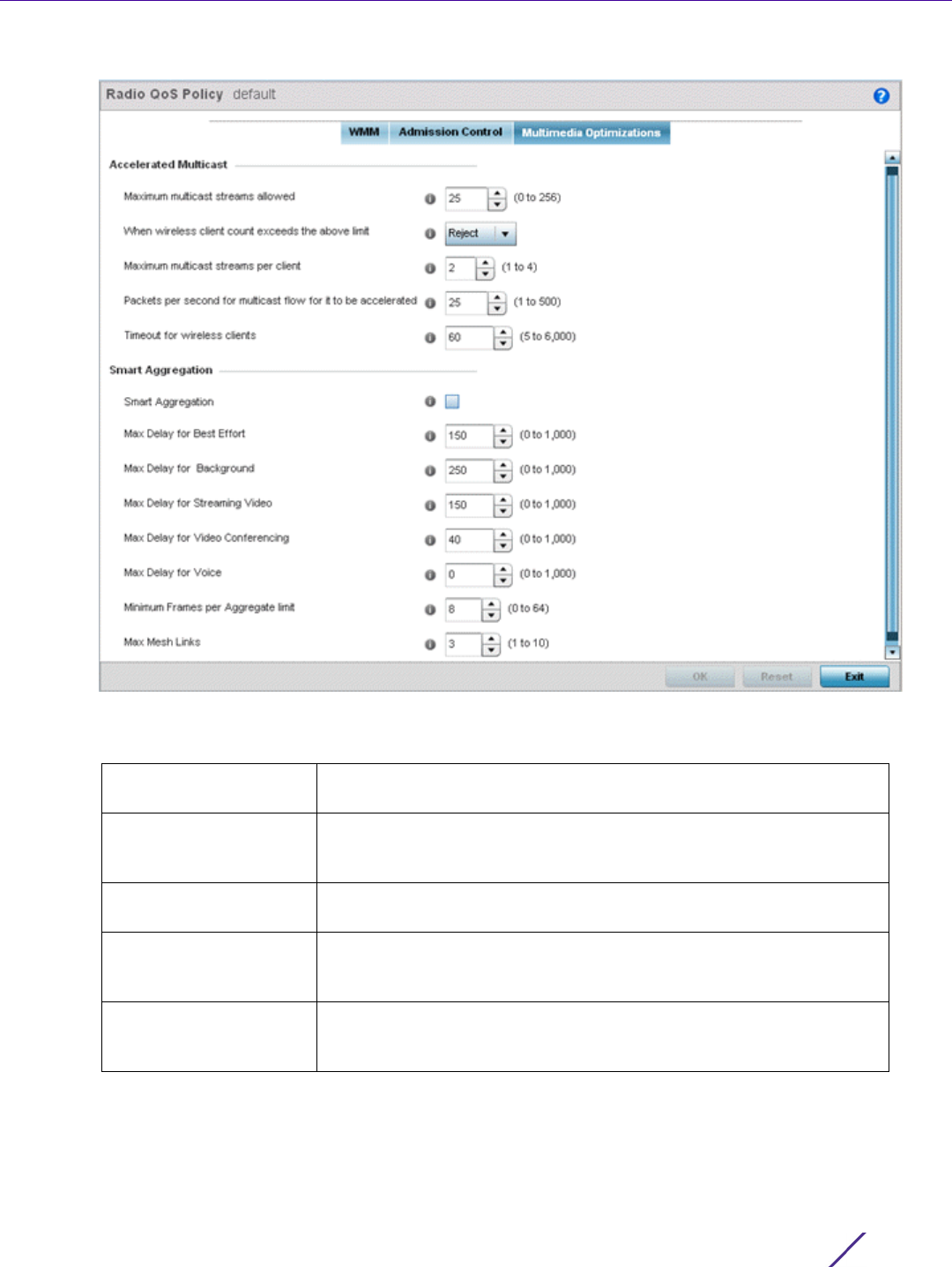
Wireless Configuration
Wireless Controller and Service Platform System Reference Guide 6 - 75
Figure 6-38 Radio QoS Policy Multimedia Optimizations screen
17 Set the following Accelerated Multicast settings for this radio QoS policy:
18 Define the following Smart Aggregation settings:
Smart Aggregation enhances frame aggregation by dynamically selecting the time when the aggregated frame
is transmitted. In a frame’s typical aggregation, an aggregated frame is sent when it meets one of these
conditions:
• When a preconfigured number of aggregated frames is reached
Maximum multicast
streams allowed
Specify the maximum number of multicast streams (between 0 and
256) permitted to use accelerated multicast. The default value is 25.
When wireless client
count exceeds the above
limit
When the wireless client count using accelerated multicast exceeds the
maximum number, set the radio to either Reject new wireless clients or
Revert existing clients to a non-accelerated state.
Maximum multicast
streams per client
Specify the maximum number of multicast streams (between 1 and 4)
wireless clients can use. The default value is 2.
Packets per second for
multicast flow for it to
be accelerated
Specify the threshold of multicast packets per second (between 1 and
500) that triggers acceleration for wireless clients. The default value is
25.
Timeout for wireless
clients
Specify a timeout value in seconds (between 5 and 6,000) for wireless
clients to revert back to a non-accelerated state. The default value is
60.

Wireless Configuration
Wireless Controller and Service Platform System Reference Guide 6 - 76
• When an administrator defined interval has elapsed since the first frame (of a set of frames to be
aggregated) was received
• When an administrator defined interval has elapsed since the last frame (not necessarily the final frame) of a
set of frames to be aggregated was received
With this enhancement, an aggregation delay is set uniquely for each traffic class. For example, voice traffic
might not be aggregated, but sent immediately. Whereas, background data traffic is set a delay for
aggregating frames, and these aggregated frames are sent.
Select OK to update the radio QoS settings for this policy. Select Reset to revert to the last saved configuration.
6.3.2 Radio QoS Configuration and Deployment Considerations
Radio QoS Policy
• Before defining a radio QoS policy, refer to the following deployment guidelines to ensure the configuration is
optimally effective:
• To support QoS, each multimedia application, wireless client and WLAN is required to support WMM.
• WMM enabled clients can co-exist with non-WMM clients on the same WLAN. Non-WMM clients are always
assigned a Best Effort access category.
• Default WMM values should be used for all deployments. Changing these values can lead to unexpected traffic
blockages, and the blockages might be difficult to diagnose.
• Overloading an Access Point radio with too much high priority traffic (especially voice) degrades overall service
quality for all users.
• TSPEC admission control is only available with newer voice over WLAN phones. Many legacy voice devices do
not support TSPEC or even support WMM traffic prioritization.
Smart Aggregation Select to enable smart aggregation and dynamically define when an
aggregated frame is transmitted. Smart aggregation is disabled by
default.
Max Delay for Best
Effort
Set the maximum time (in milliseconds) to delay best effort traffic. The
default setting is 150 milliseconds.
Max Delay for
Background
Set the maximum time (in milliseconds) to delay background traffic.
The default setting is 250 milliseconds.
Max Delay for Streaming
Video
Set the maximum time (in milliseconds) to delay streaming video
traffic. The default setting is 150 milliseconds.
Max Delay for Video
Conferencing
Set the maximum time (in milliseconds) to delay video conferencing
traffic. The default setting is 40 milliseconds.
Max Delay for Voice Set the maximum time (in milliseconds) to delay voice traffic. The
default setting is 0 milliseconds.
Minimum frames per
Aggregate limit
Set the minimum number of frames to aggregate in a frame before it
is transmitted. The default setting is 8 frames.
Max Mesh Links Set the maximum number of mesh hops for smart aggregation. The
default setting is 3.
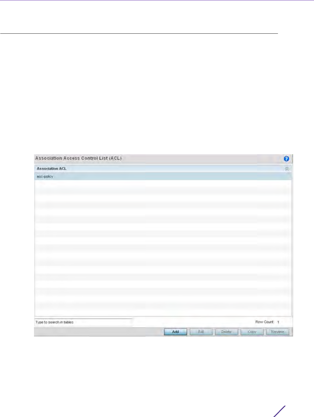
Wireless Configuration
Wireless Controller and Service Platform System Reference Guide 6 - 77
6.4 Association ACL
An association ACL is a policy-based ACL that either prevents or allows wireless clients from connecting to a
WLAN.
An association ACL affords a system administrator the ability to grant or restrict client access by specifying a
wireless client MAC address or range of MAC addresses to either include or exclude from connectivity.
Association ACLs are applied to WLANs as an additional access control mechanism. They can be applied to
WLANs from within a WLAN Policy’s Advanced configuration screen. For more information on applying an existing
Association ACL to a WLAN, see Configuring Advanced WLAN Settings.
To define an association ACL deployable with a WLAN:
1Select
Configuration > Wireless > Association ACL to display existing Association ACLs.
The Association Access Control List (ACL) screen lists those Association ACL policies created thus far. Any of
these policies can be selected and applied.
Figure 6-39 Association Access Control List (ACL) screen
2Select Add to define a new ACL configuration, Edit to modify an existing ACL configuration or Delete to remove
one. Optionally Copy or Rename a list as needed.
A unique Association ACL screen displays for defining the new ACL or modifying a selected ACL.
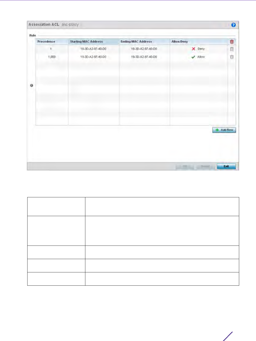
Wireless Configuration
Wireless Controller and Service Platform System Reference Guide 6 - 78
Figure 6-40 Association Access Control List (ACL) screen
3 Select the + Add Row button to add an association ACL template.
4 Set the following parameters for the creation or modification of the Association ACL:
5 Select the + Add Row button to add MAC address ranges and allow/deny designations.
6Select
OK to update the Association ACL settings. Select Reset to revert to the last saved configuration.
Association ACL If creating an new association ACL, provide a name specific to its
function. Avoid naming it after the WLAN it may support. The name
cannot exceed 32 characters.
Precedence The rules within a WLAN's ACL are applied to packets based on their
precedence values. Every rule has a unique sequential precedence
value you define. You cannot add two rules’s with the same
precedence. The default precedence is 1, so be careful to prioritize
ACLs accordingly as they are added.
Starting MAC Address Provide a starting MAC range address for clients requesting
association.
Ending MAC Address Provide an ending MAC range address for clients requesting
association.
Allow/Deny Use the drop-down menu to either Allow or Deny access if a MAC
address matches this rule.

Wireless Configuration
Wireless Controller and Service Platform System Reference Guide 6 - 79
6.4.1 Association ACL Deployment Considerations
Association ACL
Before defining an Association ACL configuration and applying it to a WLAN, refer to the following deployment
guidelines to ensure the configuration is optimally effective:
• Use the Association ACL screen strategically to name and configure ACL policies meeting the requirements of
the particular WLANs they may map to. However, be careful not to name ACLs after specific WLANs, as
individual ACL policies can be used by more than one WLAN.
• You cannot apply more than one MAC based ACL to a Layer 2 interface. If a MAC ACL is already configured on
a Layer 2 interface, and a new MAC ACL is applied to the interface, the new ACL replaces the previously
configured one.
6.5 Smart RF Policy
Self Monitoring At Run Time RF Management (Smart RF) is a WiNG innovation designed to simplify RF
configurations for new deployments, while (over time) providing on-going deployment optimization radio
performance improvements.
A Smart RF policy can reduce deployment costs by scanning the RF environment to determine the best channel
and transmit power configuration for each radio. Smart RF policies can be applied to specific RF Domains, to apply
site specific deployment configurations and self-healing values to groups of devices within pre-defined physical RF
coverage areas.
Smart RF centralizes the decision process and makes intelligent RF configuration decisions using information
obtained from the RF environment. Smart RF helps reduce ongoing management and maintenance costs by
constantly monitoring the network for external interference, neighbor interference, non-WiFi interference and client
connectivity. Smart RF then intelligently applies various algorithms to arrive at the optimal channel and power
selection for all Access Points in the network and constantly reacts to changes in the RF environment.
Smart RF also provides self-healing functions by monitoring the network in real-time and provides automatic
mitigation from potentially problematic events such as radio interference, non-WiFi interference (noise), external
WiFi interference, coverage holes and radio failures. Smart RF employs self-healing to enable a WLAN to better
maintain wireless client performance and site coverage during dynamic RF environment changes, which typically
require manual reconfiguration to resolve.
Smart RF is supported on any RF Domain manager. In standalone environments, individual controllers, service
platforms or Access Points manage the calibration and monitoring phases. In clustered environments, a single
controller or service platform is elected a Smart RF master and the remaining cluster members operate as Smart
RF clients. In cluster operation, the Smart RF master co-ordinates the calibration and configuration and during the
monitoring phase receives information from the Smart RF clients.
If a Smart RF managed radio is operating in WLAN mode on a channel requiring DFS, it will switch channels if
radar is detected.
• If Smart RF is enabled, the radio picks a channel defined in the Smart RF policy.
• If Smart RF is disabled, but a Smart RF policy is mapped, the radio picks a channels specified in the Smart RF
policy
• If no SMART RF policy is mapped, the radio selects a random channel
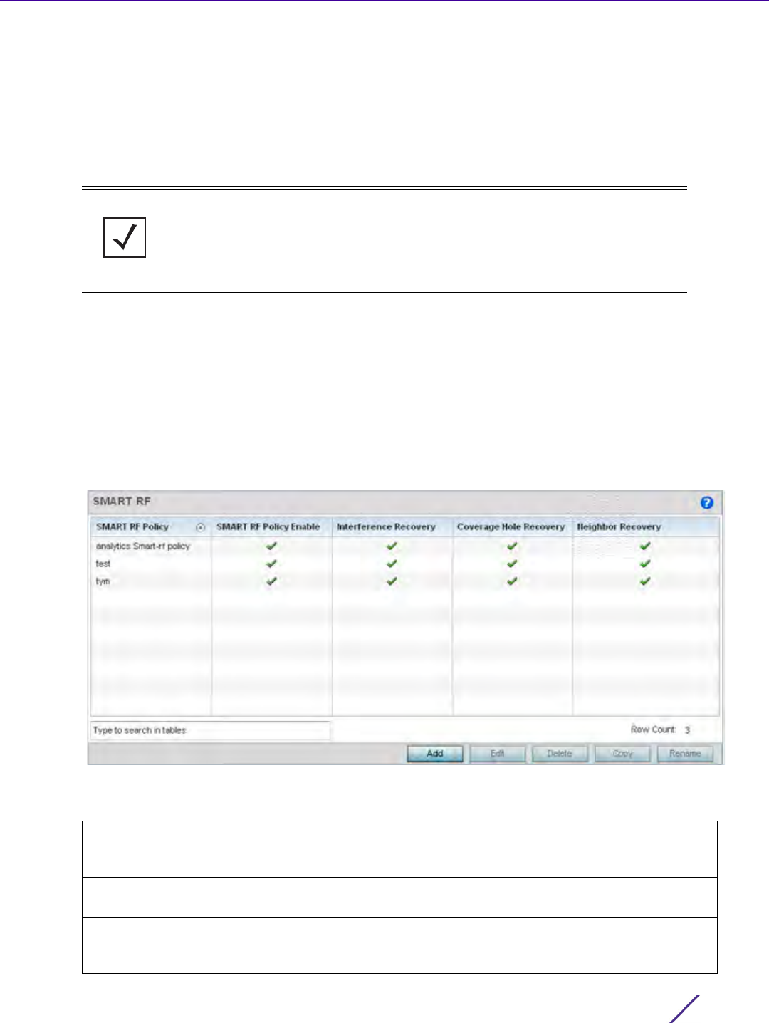
Wireless Configuration
Wireless Controller and Service Platform System Reference Guide 6 - 80
If the radio is a dedicated sensor, it stops termination on that channel if a neighboring Access Points detects radar.
The Access Point attempts to come back to its original channel (statically configured or selected by Smart RF)
after the channel evacuation period has expired.
Change this behavior using a no dfs-rehome command from the controller or service platform CLI. This keeps the
radio on the newly selected channel and prevents the radio from coming back to the original channel, even after
the channel evacuation period.
To define a Smart RF policy:
1Select
Configuration > Wireless > Smart RF Policy to display existing Smart RF policies.
The Smart RF screen lists those Smart RF policies created thus far. Any of these policies can be selected and
applied.
The user has the option of displaying the configurations of each Smart RF Policy defined thus far, or referring to
the Smart RF Browser and either selecting individual Smart RF polices or selecting existing RF Domains to review
which Smart RF policies have been applied. For more information on how RF Domains function, and how to apply
a Smart RF policy, see About RF Domains and Managing RF Domains.
Figure 6-41 Smart RF Policy screen
2 Refer to the following configuration data for existing Smart RF policies:
NOTE: RF planning must be performed to ensure overlapping coverage exists at a
deployment site for Smart RF to be a viable network performance tool. Smart RF
can only provide recovery when Access Points are deployed appropriately. Smart RF
is not a solution, it's a temporary measure. Administrators need to determine the
root cause of RF deterioration and fix it. Smart RF history/events can assist.
Smart RF Policy Displays the name assigned to the Smart RF policy when it was
initially created. The name cannot be modified as part of the edit
process.
Smart RF Policy Enable Displays a green check mark if Smart RF has been enabled for the
listed policy. A red “X” designates the policy as being disabled.
Interference Recovery Displays a green check mark if interference recovery has been enabled
for the listed policy. A red “X” designates interference recovery being
disabled.
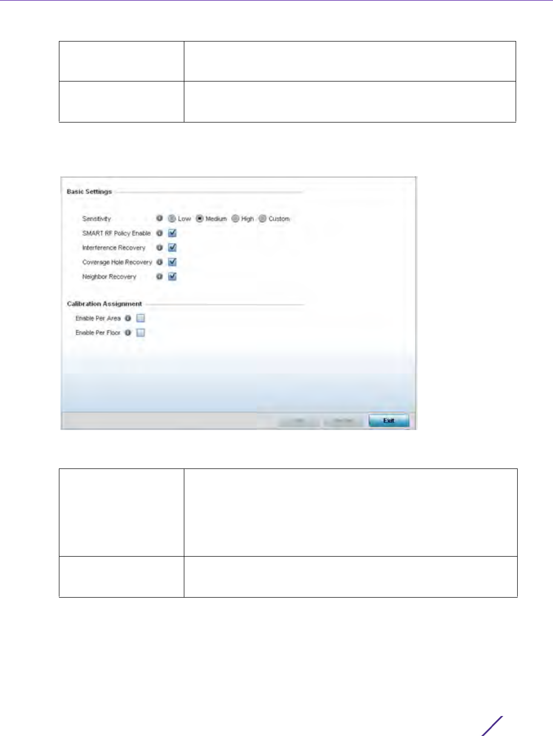
Wireless Configuration
Wireless Controller and Service Platform System Reference Guide 6 - 81
3Select Add to create a new Smart RF policy, Edit to modify the attributes of a existing policy or Delete to
remove obsolete policies from the list of those available. Optionally Copy or Rename a list as needed.
The Basic Configuration screen displays by default for the new or modified Smart RF policy.
Figure 6-42 Smart RF Basic Configuration screen
4 Refer to the Basic Settings field to enable a Smart RF policy and define its sensitivity and detector status.
Coverage Hole Recovery Displays a green check mark if coverage hole recovery has been
enabled for the listed policy. A red “X” designates coverage hole
recovery being disabled.
Neighbor Recovery Displays a green check mark if neighbor recovery has been enabled
for the listed policy. A red “X” designates neighbor recovery being
disabled.
Sensitivity Select a radio button corresponding to the desired Smart RF
sensitivity. Options include Low, Medium, High and Custom. Medium, is
the default setting. The Custom option allows an administrator to
adjust the parameters and thresholds for Interference Recovery,
Coverage Hole Recovery and Neighbor Recovery. Using the Low,
Medium (recommended) and High settings still allow these features to
be utilized.
SMART RF Policy Enable Select the Smart RF Policy Enable check box to enable this Smart RF
policy for immediate support or inclusion with a RF Domain. Smart RF
is enabled by default.

Wireless Configuration
Wireless Controller and Service Platform System Reference Guide 6 - 82
5 Refer to the Calibration Assignment field to define whether Smart RF Calibration and radio grouping is
conducted by area or floor. Both options are disabled by default.
6Select
OK to update the Smart RF Basic Configuration settings for this policy. Select Reset to revert to the last
saved configuration.
7Select
Channel and Power.
Use the Channel and Power screen to refine Smart RF power settings over both 5 and 2.4 GHz radios and
select channel settings in respect to the device channel usage.
Interference Recovery Select the check box to enable Interference Recovery from neighboring
radios and other sources of WiFi and non-WiFi interference when
excess noise and interference is detected within the Smart RF
supported radio coverage area. Smart RF provides mitigation from
interference sources by monitoring the noise levels and other RF
parameters on an Access Point radio’s current channel. When a noise
threshold is exceeded, Smart RF can select an alternative channel with
less interference. To avoid channel flapping, a hold timer is defined
which disables interference avoidance for a specific period of time
upon detection. Interference Recovery is enabled by default.
Coverage Hole Recovery Select the check box to enable Coverage Hole Recovery when a radio
coverage hole is detected within the Smart RF supported radio
coverage area. When coverage hole is detected, Smart RF first
determines the power increase needed based on the signal to noise
ratio for a client as seen by the Access Point radio. If a client’s signal to
noise value is above the threshold, the transmit power is increased
until the signal to noise rate falls below the threshold.
Neighbor Recovery Select the check box to enable Neighbor Recovery when a failed radio
is detected within the Smart RF supported radio coverage area. Smart
RF can provide automatic recovery by instructing neighboring APs to
increase their transmit power to compensate for the coverage loss.
Neighbor recovery is enabled by default when the sensitivity setting is
medium.
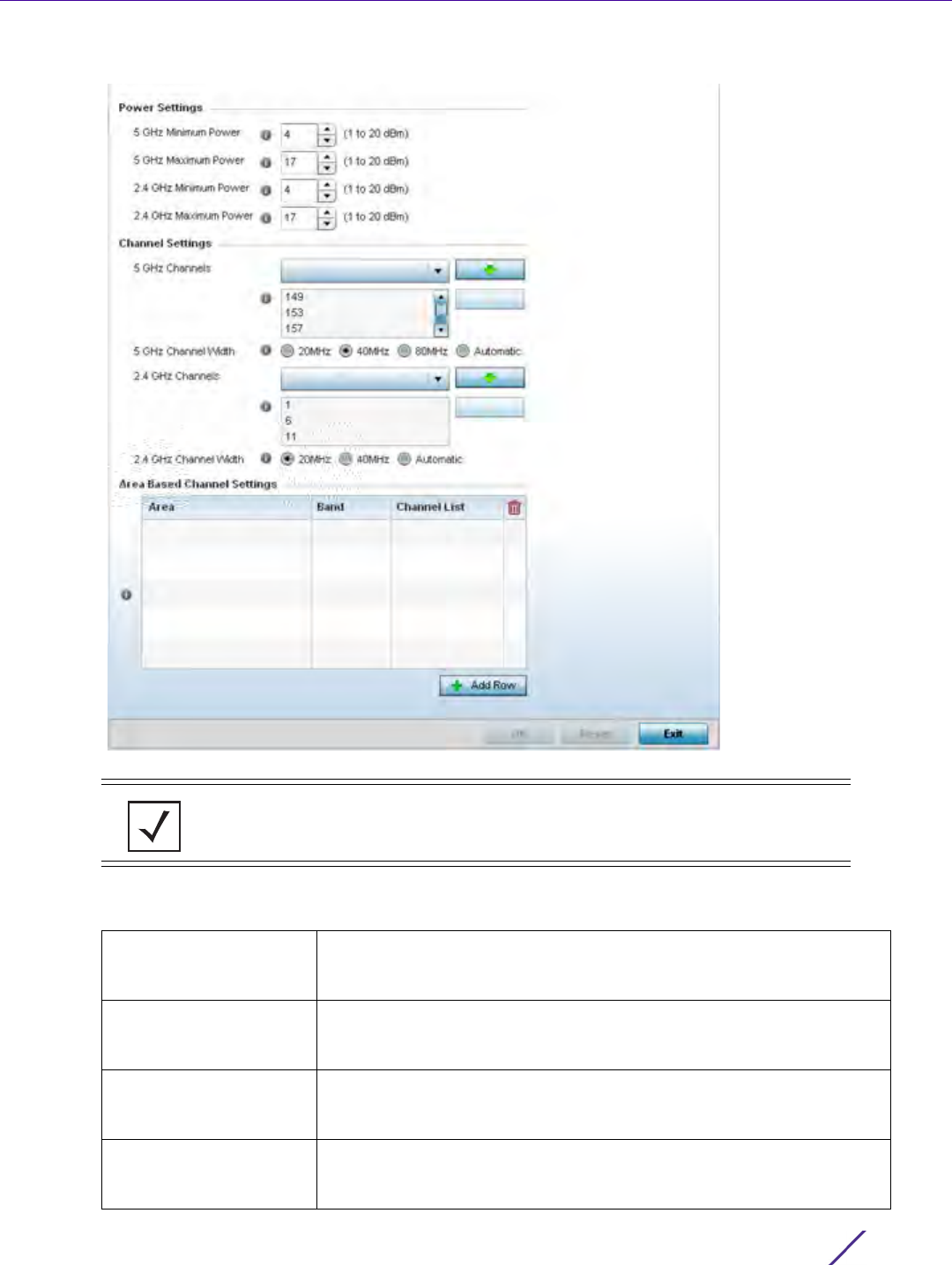
Wireless Configuration
Wireless Controller and Service Platform System Reference Guide 6 - 83
Figure 6-43 Smart RF Channel and Power screen
8 Refer to the Power Settings field to define Smart RF recovery settings for either the selected 5.0 GHz (802.11a)
or 2.4 GHz (802.11bg) radio.
NOTE: The Power Settings and Channel Settings parameters are only enabled when
Custom or Medium is selected as the Sensitivity setting from the Basic Configuration
screen.
5 GHz Minimum Power Use the spinner control to select a 1 - 20 dBm minimum power level for
Smart RF to assign to a radio in the 5 GHz band. 4 dBm is the default
setting.
5 GHz Maximum Power Use the spinner control to select a 1 - 20 dBm maximum power level
Smart RF can assign a radio in the 5 GHz band. 17 dBm is the default
setting.
2.4 GHz Minimum Power Use the spinner control to select a 1 - 20 dBm minimum power level
Smart RF can assign a radio in the 2.4 GHz band. 4 dBm is the default
setting.
2.4 GHz Maximum
Power
Use the spinner control to select a 1 - 20 dBm maximum power level
Smart RF can assign a radio in the 2.4 GHz band. 17 dBm is the default
setting.

Wireless Configuration
Wireless Controller and Service Platform System Reference Guide 6 - 84
9 Set the following Channel Settings for the 5.0 GHz and 2.4 GHz radios:
10 Select + Add Row and set the following Area Based Channel Settings for the Smart RF policy:
11 Select OK to update the Smart RF Channel and Power settings for this policy. Select Reset to revert to the last
saved configuration.
12 Select the Scanning Configuration tab.
5 GHz Channels Use the Select drop-down menu to define the 5 GHz channels used for
Smart RF assignments.
5 GHz Channel Width 20 and 40 MHz channel widths are supported by the 802.11a radio. 20/
40 MHz operation (the default setting for the 5 GHz radio) allows the
Access Point to receive packets from clients using 20 MHz of
bandwidth while transmitting a packet using 40 MHz bandwidth. This
mode is supported for 11n users on both the 2.4 and 5 GHz radios. If an
11n user selects two channels (a Primary and Secondary channel), the
system is configured for dynamic 20/40 operation. When 20/40 is
selected, clients can take advantage of wider channels. 802.11n clients
experience improved throughput using 40 MHz while legacy clients
(either 802.11a or 802.11b/g depending on the radio selected) can still
be serviced without interruption using 20 MHz. Select Automatic to
enable automatic assignment of channels to working radios to avoid
channel overlap and avoid interference from external RF sources.
40MHz is the default setting. If deploying an 802.11ac supported
Access Point, 80MHz channel width options are available as well.
2.4 GHz Channels Set the 2.4 GHz channels used in Smart RF scans.
2.4 GHz Channel Width 20 and 40 MHz channel widths are supported by the 802.11a radio. 20
MHz is the default setting for 2.4 GHz radios. 20/40 MHz operation
(the default setting for the 5 GHz radio) allows the Access Point to
receive packets from clients using 20 MHz of bandwidth while
transmitting a packet using 40 MHz bandwidth. This mode is
supported for 11n users on both the 2.4 and 5 GHz radios. If an 11n user
selects two channels (a Primary and Secondary channel), the system is
configured for dynamic 20/40 operation. When 20/40 is selected,
clients can take advantage of wider channels. 802.11n clients
experience improved throughput using 40 MHz while legacy clients
(either 802.11a or 802.11b/g depending on the radio selected) can still
be serviced without interruption using 20 MHz. Select Automatic to
enable automatic assignment of channels to working radios to avoid
channel overlap and avoid interference from external RF sources.
20MHz is the default setting.
Area Specify the deployment area assigned to the listed policy when
deployed a means of identifying the devices physical locations.
Band Specify the radio band, either 2.4 GHz or 5 GHz, for the Smart RF
policy assigned to the specified area.
Channel List Specify the channels associated with the Smart RF policy for the
specified area and band.
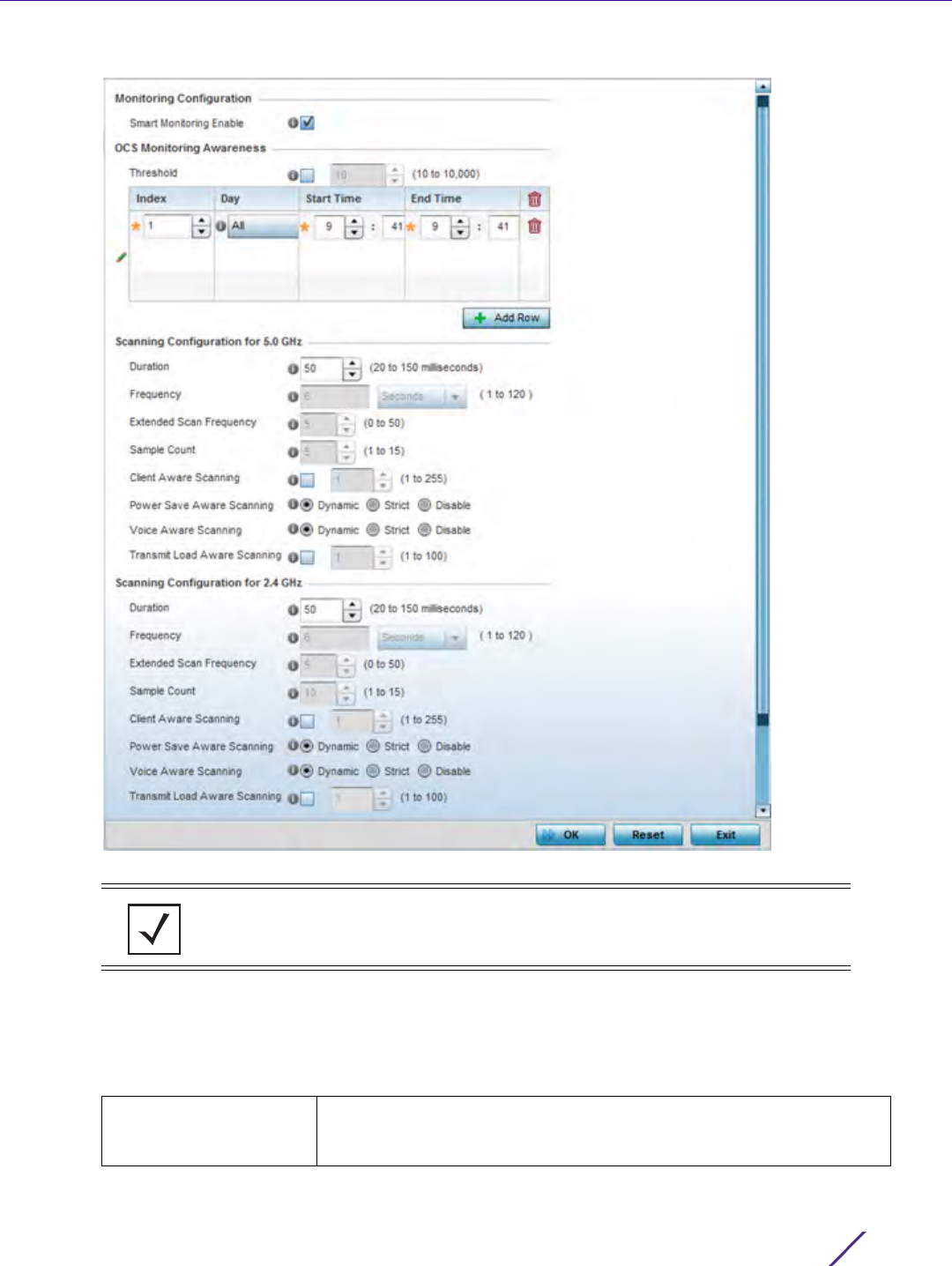
Wireless Configuration
Wireless Controller and Service Platform System Reference Guide 6 - 85
Figure 6-44 Smart RF Scanning Configuration screen
13 Enable or disable Smart Monitoring Enable. The feature is enabled by default.
When enabled, detector radios monitor their coverage areas for potential failed peers or coverage area holes
requiring transmission adjustments for coverage compensation.
14 Select + Add Row and set OCS Monitoring Awareness Settings for the Smart RF policy:
NOTE: The monitoring and scanning parameters within the Scanning Configuration
screen are only enabled when Custom is selected as the Sensitivity setting from the
Basic Configuration screen.
Threshold Select this option and specify a threshold from 10 - 10,000. When the
threshold is reached awareness settings are overridden with the values
specified in the table.

Wireless Configuration
Wireless Controller and Service Platform System Reference Guide 6 - 86
15 Set the following Scanning Configurations for both the 2.4 and 5.0 GHz radio bands:
Index Select an Index value from 1 - 3 for awareness overrides. The overrides
are executed based on index, with the lowest index being executed
first.
Day Use the drop-down menu to select a day of the week to apply the
override. Selecting All will apply the policy every day. Selecting
weekends will apply the policy on Saturdays and Sundays only.
Selecting weekdays will apply the policy on Monday, Tuesday,
Wednesday, Thursday and Friday. Selecting individual days of the week
will apply the policy only on the selected day.
Start Time This value sets the starting time of day(s) that the overrides will be
activated. Use the spinner controls to select the hour and minute, in
12h time format. Then use the radio button to choose AM or PM.
End Time This value sets the ending time of day(s) that the overrides will be
disabled. Use the spinner controls to select the hour and minute, in 12h
time format. Then use the radio button to choose AM or PM.
Duration Set a channel scan duration (from 20 - 150 milliseconds) Access Point
radios use to monitor devices within the network and, if necessary,
perform self healing and neighbor recovery to compensate for
coverage area losses within a RF Domain. The default setting is 50
milliseconds for both the 2.4 and 5 GHz bands.
Frequency Set the scan frequency using the drop-down menu. Set a scan
frequency in either Seconds (1 - 120) or Minutes (0 - 2). The default
setting is 6 seconds for both the 5 and 2.4 GHz bands.
Extended Scan
Frequency
Use the spinner control to set an extended scan frequency between 0 -
50. This is the frequency radios scan channels on other than their peer
radios. The default setting is 5 for both the 5 and 2.4 GHz bands.
Sample Count Use the spinner control to set a sample scan count value between 1 -
15. This is the number of RF readings radios gather before they send
the data to the Smart RF master. The default setting is 5 for both the 5
and 2.4 GHz bands
Client Aware Scanning Set a client awareness count (number of clients from 1 - 255) for off
channel scans of either the 5 GHz or 2.4 GHz band.
Power Save Aware
Scanning
Select either the Dynamic, Strict or Disable radio button to define how
power save scanning is set for Smart RF. Strict disables smart
monitoring as long as a power save capable client is associated to a
radio. Dynamic disables smart monitoring as long as there is data
buffered for a power save client at the radio. The default setting is
Dynamic for both the 5 and 2.4 GHz bands.
Voice Aware Scanning Select either the Dynamic, Strict or Disable radio button to define how
voice aware recognition is set for Smart RF. Strict disables smart
monitoring as long as a voice client is associated to a radio. Dynamic
disables smart monitoring as long as there is data buffered for a voice
client at the radio. The default setting is Dynamic for both the 5 and
2.4 GHz bands.
Transmit Load Aware
Scanning
Select this option to set a transmit load percentage from 1 - 100
serving as a threshold before scanning is avoided for an Access Point’s
2.4 GHz radio.
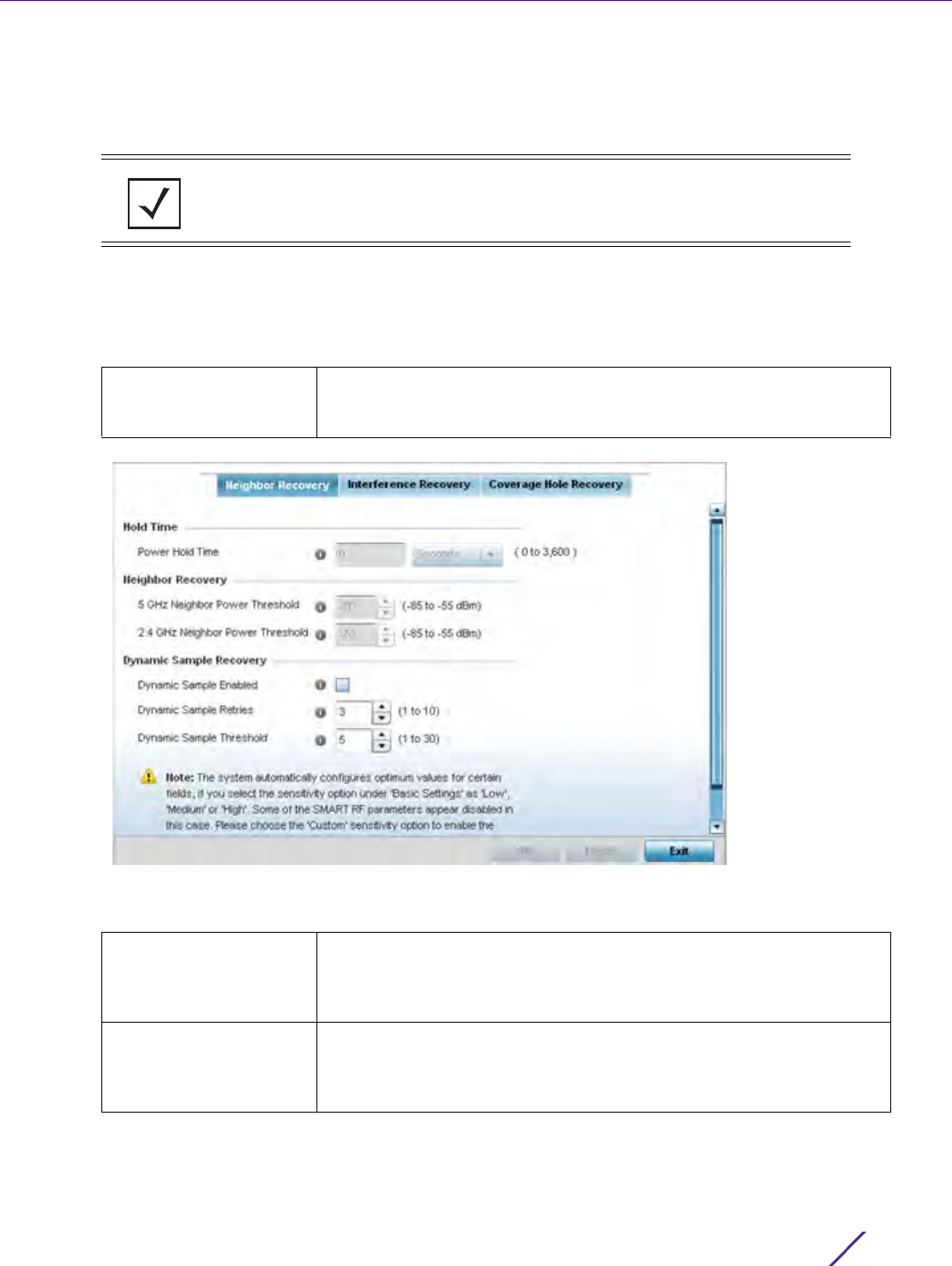
Wireless Configuration
Wireless Controller and Service Platform System Reference Guide 6 - 87
16 Select OK to update the Smart RF Scanning Configuration settings for this policy. Select Reset to revert to the
last saved configuration.
17 Select Recovery.
The Neighbor Recovery tab displays by default. Use the Neighbor, Interference and Coverage Hole recovery
tabs to define how 5 and 2.4 GHz radios compensate for failed neighbor radios, interference impacting the
Smart RF supported network and detected coverage holes requiring neighbor radio intervention.
18 Set the Hold Time for the Smart RF configuration.
Figure 6-45 Smart RF Advanced Configuration screen - Neighbor Recovery tab
19 Set the following Neighbor Recovery parameters:
NOTE: The recovery parameters within the Neighbor Recovery, Interference and
Coverage Hole Recovery tabs are only enabled when Custom is selected as the
Sensitivity setting from the Basic Configuration screen.
Power Hold Time Defines the minimum time between two radio power changes during
neighbor recovery. Set the time in either Seconds (0 - 3,600), Minutes
(0 - 60) or Hours (0 - 1). The default setting is 0 seconds.
5 GHz Neighbor Power
Threshold
Use the spinner control to set a value between -85 to -55 dBm the 5.0
GHz radio uses as a maximum power increase threshold if the radio is
required to increase its output power to compensate for a failed radio
within its wireless radio coverage area. The default value is -70 dBm.
2.4 GHz Neighbor Power
Threshold
Use the spinner control to set a value between -85 to -55 dBm the 2.4
GHz radio uses as a maximum power increase threshold if the radio is
required to increase its output power to compensate for a failed radio
within its wireless radio coverage area. The default value is -70 dBm.
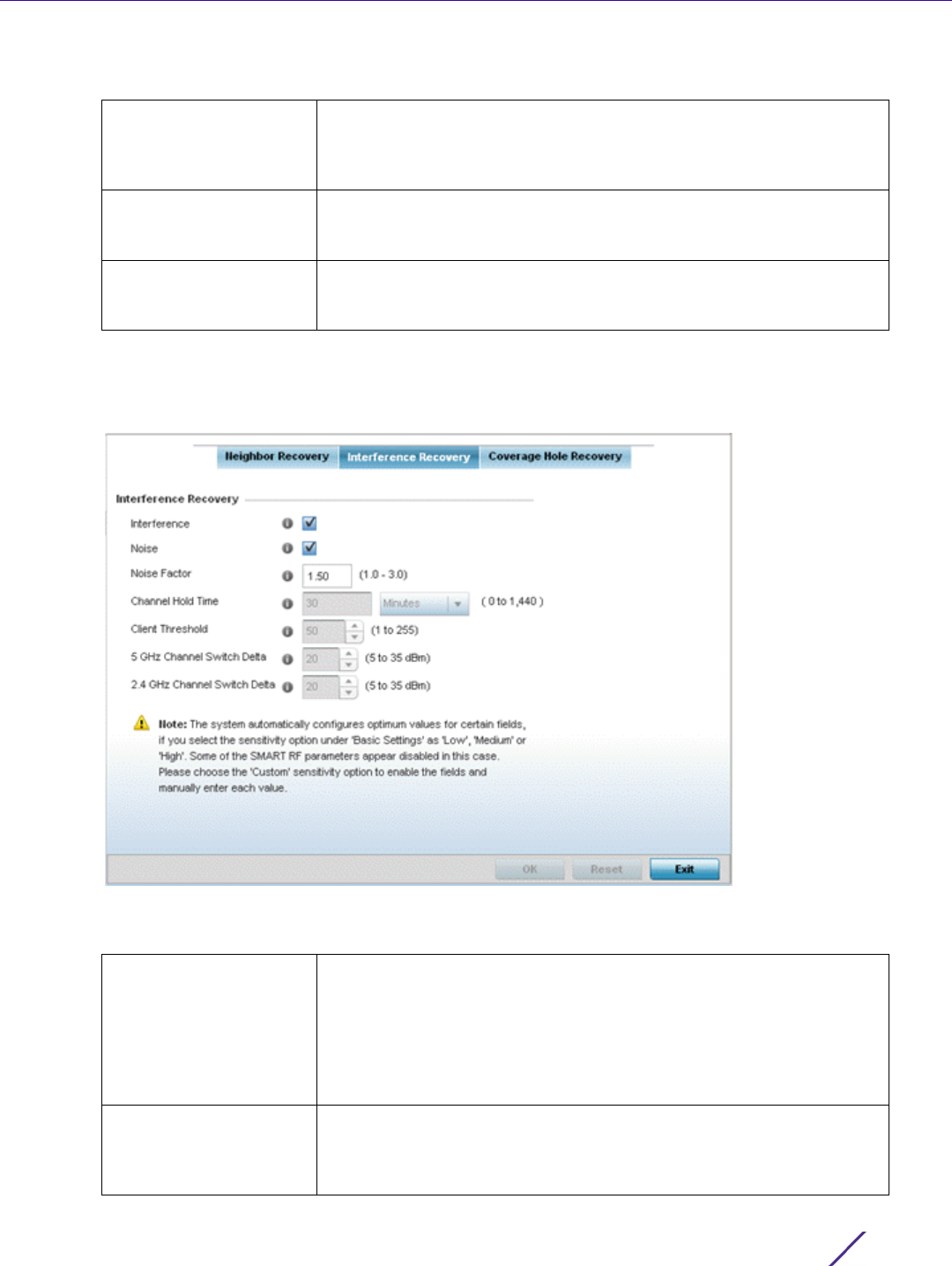
Wireless Configuration
Wireless Controller and Service Platform System Reference Guide 6 - 88
20 Set the following Dynamic Sample Recovery parameters:
21 Select OK to update the Smart RF Neighbor Recovery settings for this policy. Select Reset to revert to the last
saved configuration.
22 Select the Interference Recovery tab.
Figure 6-46 Smart RF Advanced Configuration screen - Interference Recovery tab
23 Set the following Interference Recovery parameters:
Dynamic Sample
Enabled
Select this option to enable dynamic sampling. Dynamic sampling
enables an administrator to define how Smart RF adjustments are
triggered by locking retry and threshold values. This setting is disabled
by default.
Dynamic Sample Retries Set the number of retries (from 1 - 10) attempted before a power level
adjustment is implemented to compensate for a potential coverage
hole. The default setting is 3.
Dynamic Sample
Threshold
Set the minimum number of sample reports (from 1- 30) before a
Smart RF power compensation requires dynamic sampling. The default
setting is 5.
Interference Select the check box to allow the Smart RF policy to scan for excess
interference from supported radio devices. WLANs are susceptible to
sources of interference, such as neighboring radios, cordless phones,
microwave ovens and Bluetooth devices. When interference for WiFi
sources is detected, Smart RF supported devices can change the
channel and move to a cleaner channel. This feature is enabled by
default.
Noise Select the check box to allow the Smart RF policy to scan for excess
noise from WiFi devices. When detected, Smart RF supported devices
can change their channel and move to a cleaner channel. This feature
is enabled by default.
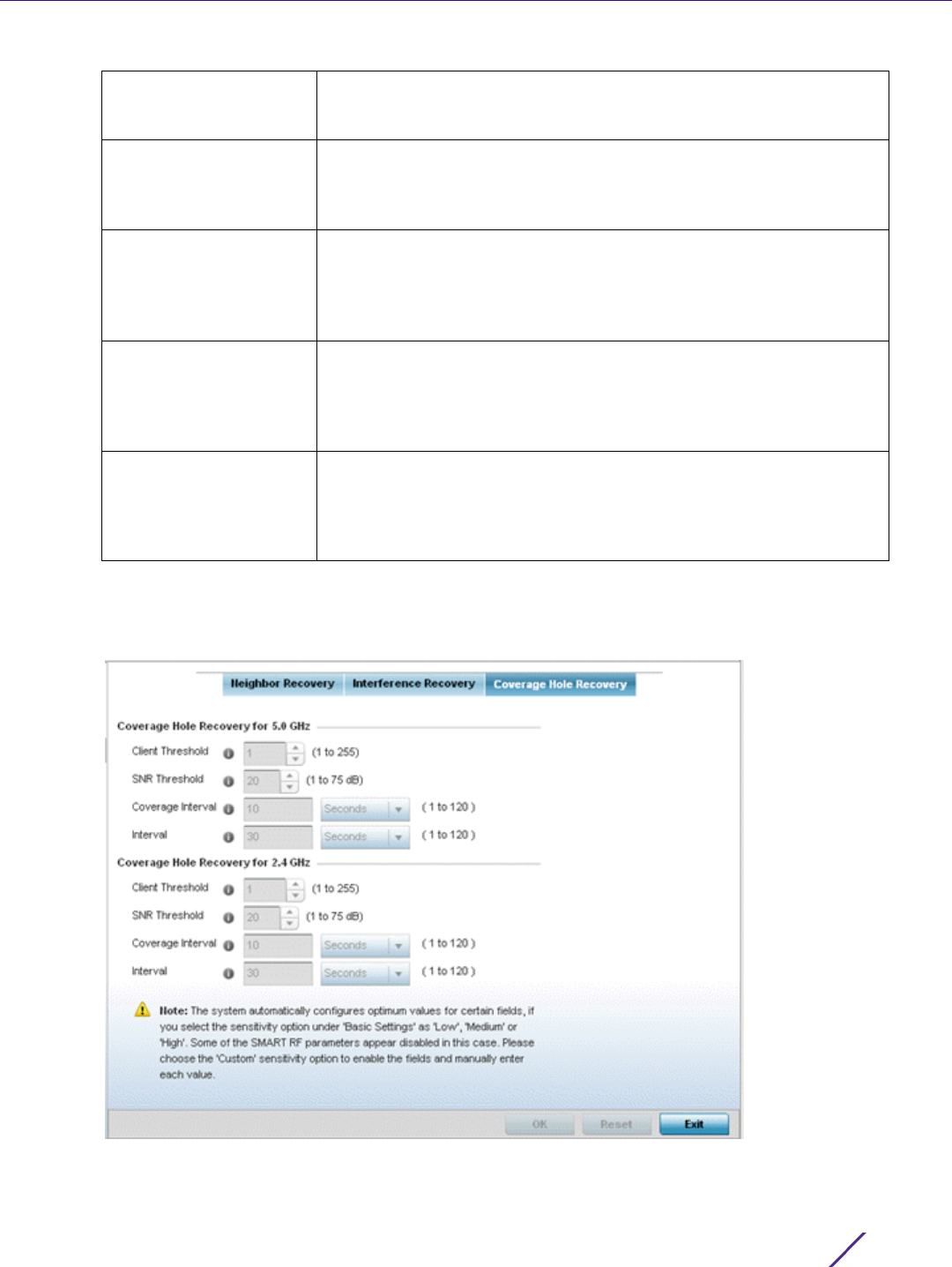
Wireless Configuration
Wireless Controller and Service Platform System Reference Guide 6 - 89
24 Select OK to update the Smart RF Interference Recovery settings for this policy. Select Reset to revert to the
last saved configuration.
25 Select the Coverage Hole Recovery tab.
Figure 6-47 Smart RF Advanced Configuration screen - Coverage Hole Recovery tab
Noise Factor Define the noise factor (level of network interference detected) taken
into account by Smart RF during interference recovery calculations.
The default setting is 1.50.
Channel Hold Time Defines the minimum time between channel changes during neighbor
recovery. Set the time in either Seconds (0 - 86,400), Minutes (0 -
1,440) or Hours (0 - 24) or Days (0 - 1). The default setting is 30
minutes.
Client Threshold Use the spinner to set a client threshold for the Smart RF policy
between 1 - 255. If the set threshold number of clients are connected
to a radio, it does not change its channel even though it requires one,
based on the interference recovery determination made by the smart
master. The default is 50.
5 GHz Channel Switch
Delta
Use the spinner to set a channel interference delta (between 5 - 35
dBm) for the 5.0 GHz radio. This parameter is the difference between
interference levels on the current channel and a prospective channel. If
the difference is below the configured threshold, the channel will not
change. The default setting is 20 dBm.
2.4 GHz Channel Switch
Delta
Use the spinner to set a channel interference delta (between 5 - 35
dBm) for the 2.4 GHz radio. This parameter is the difference between
interference levels on the current channel and a prospective channel. If
the difference is below the configured threshold, the channel will not
change. The default setting is 20 dBm.

Wireless Configuration
Wireless Controller and Service Platform System Reference Guide 6 - 90
26 Set the following Coverage Hole Recovery for 2.4 GHz and 5.0 GHz parameters:
27 Select OK to update the Smart RF coverage hole recovery settings for this policy. Select Reset to revert to the
last saved configuration.
6.5.1 Smart RF Configuration and Deployment Considerations
Smart RF Policy
Before defining a Smart RF policy, refer to the following deployment guidelines to ensure the configuration is
optimally effective:
• The Smart RF calibration process impacts associated users and should not be run during business or
production hours. The calibration process should be performed during scheduled maintenance intervals or
non-business hours.
• For Smart RF to provide effective recovery, RF planning must be performed to ensure overlapping coverage
exists at the deployment site. Smart RF can only provide recovery when Access Points are deployed
appropriately. Smart RF is not a solution, it's a temporary measure. Administrators need to determine the
root cause of RF deterioration and fix it. Smart RF history/events can assist.
If a Smart RF managed radio is operating in WLAN mode on a channel requiring DFS, it will switch channels if
radar is detected.
• If Smart RF is enabled, the radio picks a channel defined in the Smart RF policy
• If Smart RF is disabled, but a Smart RF policy is mapped, the radio picks a channels specified in the Smart
RF policy
• If no SMART RF policy is mapped, the radio selects a random channel
If the radio is a dedicated sensor, it stops termination on that channel if a neighboring Access Points detects radar.
The Access Point attempts to come back to its original channel (statically configured or selected by Smart RF)
after the channel evacuation period has expired.
Change this behavior using a no dfs-rehome command from the controller or service platform CLI. This keeps the
radio on the newly selected channel and prevents the radio from coming back to the original channel, even after
the channel evacuation period.
Client Threshold Use the spinner to set a client threshold for the Smart RF policy
between 1 - 255. This is the minimum number of clients a radio should
have associated in order for coverage hole recovery to trigger. The
default setting is 1.
SNR Threshold Use the spinner control to set a signal to noise threshold (between 1 -
75 dB). This is the signal to noise threshold for an associated client as
seen by its associated Access Point radio. When exceeded, the radio
increases its transmit power in order to increase coverage for the
associated client. The default value is 20 dB.
Coverage Interval Define the interval coverage hole recovery should be initiated after a
coverage hole is detected. The default is 10 seconds for both the 2.4
and 5.0 GHz radios.
Interval Define the interval coverage hole recovery should be conducted before
a coverage hole is detected. The default is 30 seconds for both the 2.4
and 5.0 GHz radios.
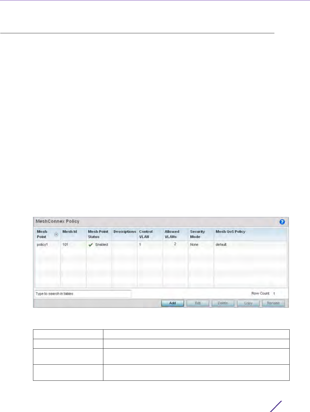
Wireless Configuration
Wireless Controller and Service Platform System Reference Guide 6 - 91
6.6 MeshConnex Policy
MeshConnex is a mesh networking technology that is comparable to the 802.11s mesh networking specification.
MeshConnex meshing uses a hybrid proactive/on-demand path selection protocol, similar to Ad hoc On Demand
Distance Vector (AODV) routing protocols. This allows it to form efficient paths using multiple attachment points
to a distribution WAN, or form purely ad-hoc peer-to-peer mesh networks in the absence of a WAN. Each device
in the MeshConnex mesh proactively manages its own path to the distribution WAN, but can also form peer-to-
peer paths on demand to improve forwarding efficiency. MeshConnex is not compatible with MiNT Based meshing,
though the two technologies can be enabled simultaneously in certain circumstances.
MeshConnex is designed for large-scale, high-mobility outdoor mesh deployments. MeshConnex continually
gathers data from beacons and transmission attempts to estimate the efficiency and throughput of each MP-to-MP
link. MeshConnex uses this data to dynamically form and continually maintain paths for forwarding network
frames.
In MeshConnex systems, a mesh point (MP) is a virtual mesh networking instance on a device, similar to a WLAN
AP. On each device, up to 4 MPs can be created and 2 can be created per radio. MPs can be configured to use one
or both radios in the device. If the MP is configured to use both radios, the path selection protocols will continually
select the best radio to reach each destination. Each MP participates in a single Mesh Network, defined by the
MeshID. The MeshID is typically a descriptive network name, similar to the SSID of a WLAN. All MPs configured to
use the same MeshID attempt to form a mesh and interoperate. The MeshID allows overlapping mesh networks to
discriminate and disregard MPs belonging to different networks.
To define a MeshConnex policy:
1Select
Configuration > Wireless > MeshConnex Policy to display existing MeshConnex policies.
Figure 6-48 MeshConnex Policy screen
2 Refer to the following configuration data for existing MeshConnex policies:
Mesh Point Name Displays the administrator assigned name of each listed mesh point.
Mesh ID Displays the IDs (mesh identifiers) assigned to mesh points.
Mesh Point Status Specified the status of each configured mesh point (either Enabled or
Disabled).
Descriptions Displays any descriptive text provided by the administrator for each
configured mesh point.
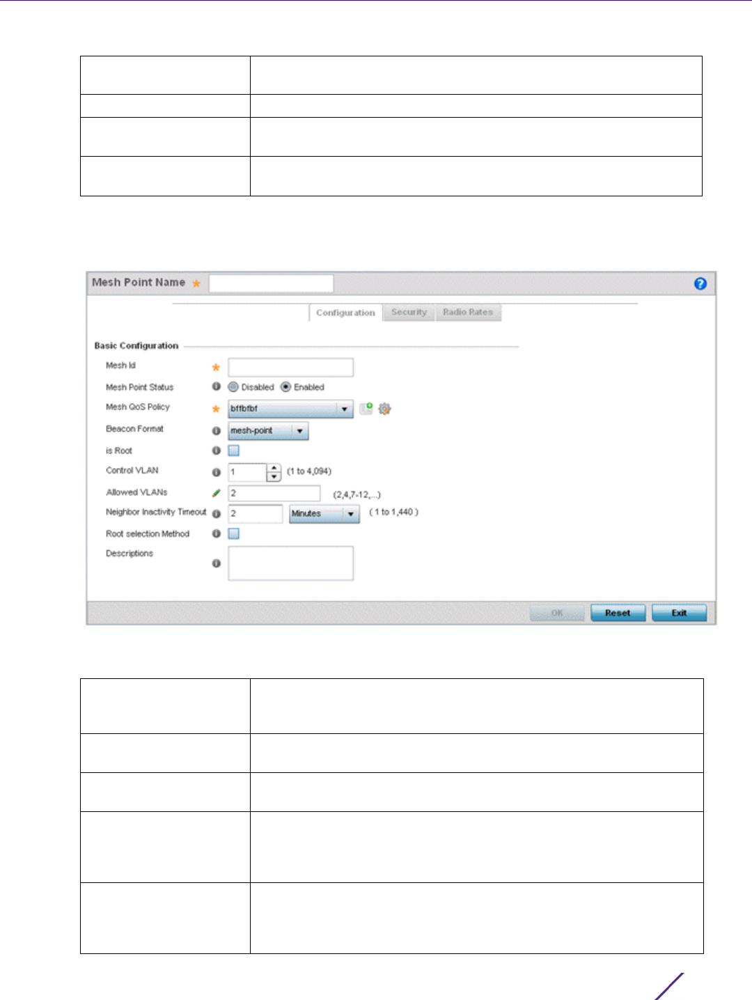
Wireless Configuration
Wireless Controller and Service Platform System Reference Guide 6 - 92
3Select Add to create a new MeshConnex policy, Edit to modify the attributes of a existing policy or Delete to
remove obsolete policies from the list of those available. Optionally Copy or Rename a policy as needed.
The Configuration screen displays by default for the new or modified MeshConnex policy.
Figure 6-49 MeshConnex Configuration screen
4 Refer to the Basic Configuration field to define a MeshConnex configuration.
Control VLAN Displays the VLAN (virtual interface ID) for the control VLAN on each
of the configured mesh points.
Allowed VLANs Displays the list of VLANs allowed on each configured mesh point.
Security Mode Displays the security assigned to each configured mesh point. The field
displays None for no security or PSK for pre-shared key authentication.
Mesh QoS Policy Displays the mesh Quality of Service policy associated to each
configured mesh point.
Mesh Point Name Specify a name for the new mesh point. The name should be
descriptive to easily differentiate it from other mesh points. This field is
mandatory.
Mesh Id Specify a 32 character maximum mesh identifier for this mesh point.
This field is optional.
Mesh Point Status To enable this mesh point, click the Enabled radio button. To disable
the mesh point click the Disabled button.The default value is enabled.
Mesh QoS Policy Use the drop-down menu to specify the mesh Quality of Service policy
to use on this mesh point. This value is mandatory. If no suitable Mesh
QoS policies exist, click the create icon to create a new Mesh QoS
policy.
Beacon Format Use the drop-down menu to specify the format for beacon
transmissions. To use Access Point style beacons, select access-point
from the drop-down menu. To use mesh point style beacons, select
mesh-point. The default value is mesh-point.
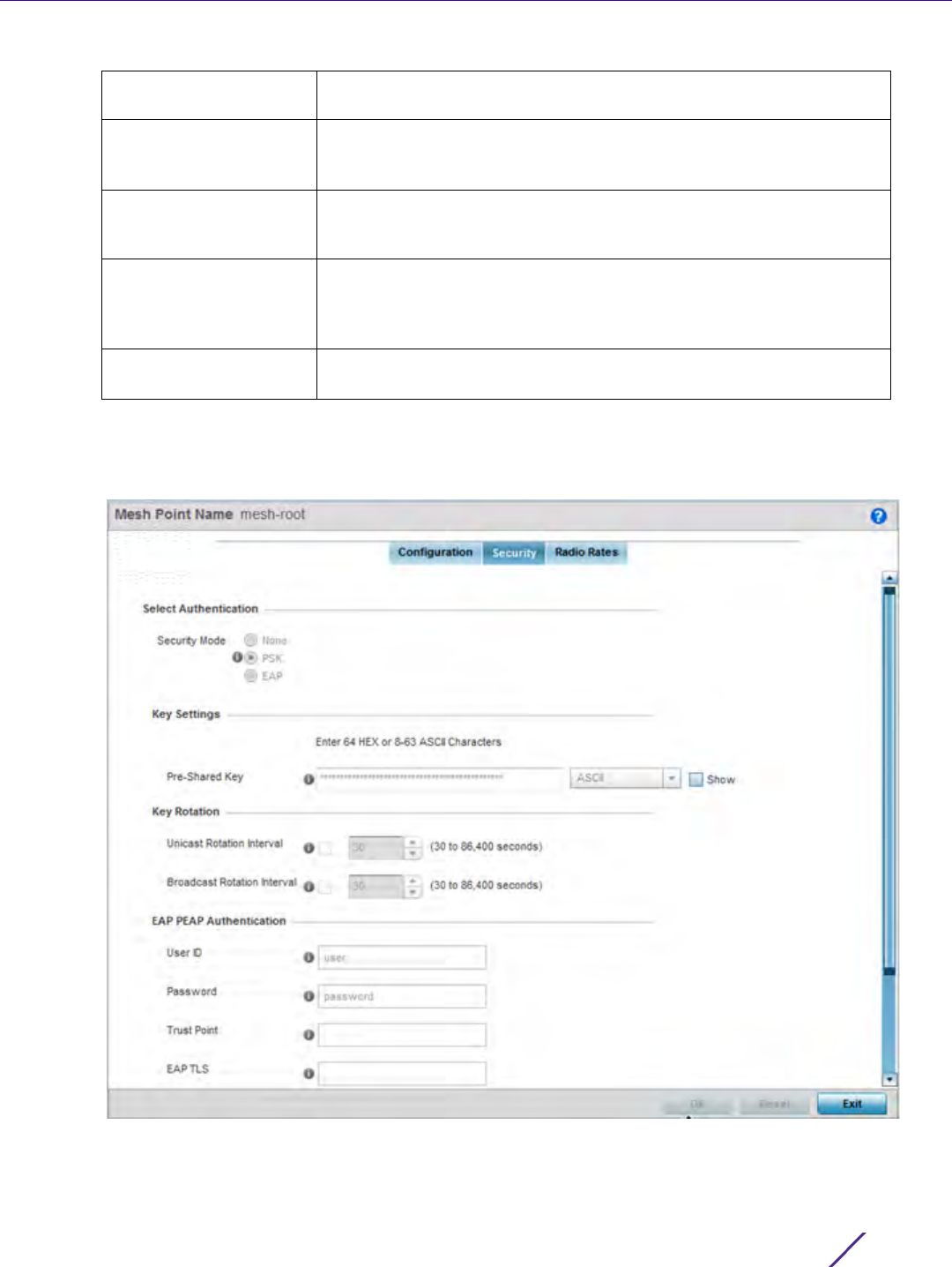
Wireless Configuration
Wireless Controller and Service Platform System Reference Guide 6 - 93
5Select OK to update the MeshConnex Configuration settings for this policy. Select Reset to revert to the last
saved configuration.
6 Select the Security tab.
Figure 6-50 MeshConnex Security screen
Is Root Select this option to specify the mesh point as a root in the mesh
topology.
Control VLAN Use the spinner control to specify a VLAN to carry meshpoint control
traffic. The valid range for control VLAN is between 1 and 4094. The
default value is VLAN 1.
Allowed VLANs Specify the VLANs allowed to pass traffic on the mesh point. Separate
all VLANs with a comma. To specify a range of allowed VLANs
separate the starting VLAN and the ending VLAN with a hyphen.
Neighbor Inactivity
Timeout
Specify a timeout in seconds, minutes, hours or days, up to a maximum
of 1 day. This represents the allowed interval between frames received
from a neighbor before their client privileges are revoked. The default
value is 2 minutes.
Description Enter a 64 character maximum description about the mesh point
configuration.

Wireless Configuration
Wireless Controller and Service Platform System Reference Guide 6 - 94
7 Refer to the Select Authentication field to define an authentication method for the mesh policy.
8 Set the following Key Settings for the mesh point:
9 Set the following Key Rotation for the mesh point:
10 Set the following EAP PEAP Authentication settings if using EAP to secure the mesh point:
11 Select OK to save the changes made to the configuration. Select Reset to revert to the last saved configuration.
12 Select the Radio Rates tab.
Security Mode Select a security authentication mode for the mesh point. Select None
to have no authentication for the mesh point. Select EAP to use a
secured credential exchange, dynamic keying and strong encryption. If
selecting EAP, refer to the EAP PEAP Authentication field at the
bottom of the screen and define the credentials of an EAP user and
trustpoint. Select PSK to set a pre-shared key as the authentication for
the mesh-point. If PSK is selected, enter a pre-shared key in the Key
Settings field.
Pre-Shared Key When the security mode is set as PSK, enter a 64 character HEX or an
8-63 ASCII character passphrase used for authentication on the mesh
point.
Unicast Rotation Interval Define an interval for unicast key transmission (30 -86,400 seconds).
Broadcast Rotation
Interval
When enabled, the key indices used for encrypting/decrypting
broadcast traffic is alternatively rotated based on the defined interval.
Define an interval for broadcast key transmission in seconds (30-
86,400). Key rotation enhances the broadcast traffic security on the
WLAN.
User ID Create a 32 character maximum user name for a peap-mschapv2
authentication credential exchange.
Password Define a 32 character maximum password for the EAP PEAP username
created above.
Trust Point Provide the 64 character maximum name of the trustpoint used for
installing the CA certificate and validating the server certificate.
EAP TLS Provide the 64 character maximum name of the trustpoint used for
installing the client certificate, client private key and CA certificate.
Type Use the drop-down menu to select the EAP authentication method
used by the supplicant. The default EAP type is PEAP-MS-CHAPv2.
EAP Identity Enter the 32 character maximum identity string used during phase 1
authentication. This string does not need to represent the identity of
the user, rather an anonymous identity string.
AAA Policy Select an existing AAA Policy from the drop-down menu to apply to
this user’s mesh point EAP configuration. Authentication, authorization,
and accounting (AAA) is a framework for intelligently controlling
access to the network, enforcing user authorization policies and
auditing and tracking usage. These combined processes are central for
securing wireless client resources and wireless network data flows.
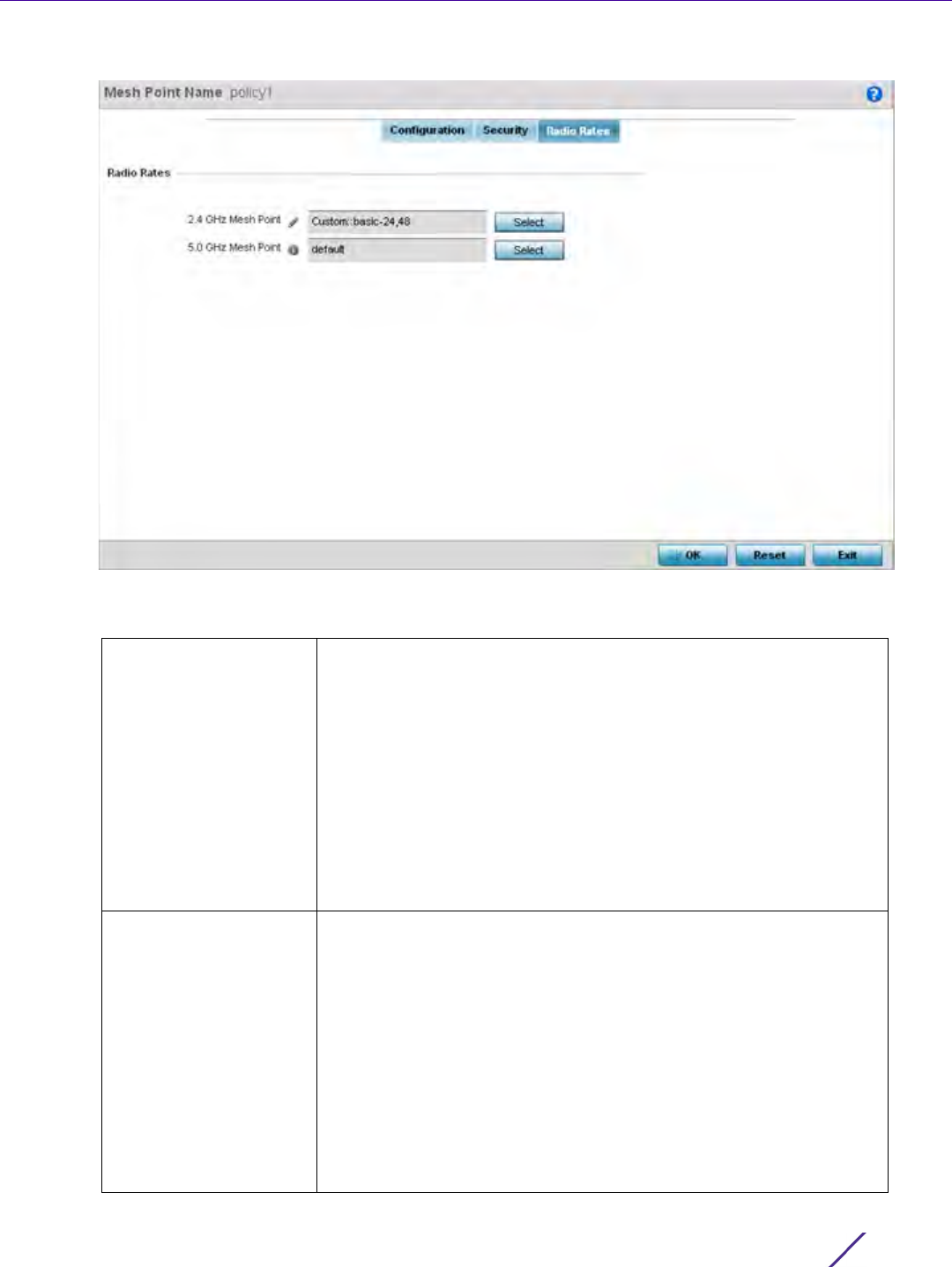
Wireless Configuration
Wireless Controller and Service Platform System Reference Guide 6 - 95
Figure 6-51 Radio Rate Settings
13 Set the following Radio Rates for both the 2.4 and 5 GHz radio bands:
2.4 GHz Mesh Point Click the Select button to configure radio rates for the 2.4 GHz band.
Define both minimum Basic and optimal Supported rates as required
for the 802.11b rates, 802.11g rates and 802.11n rates supported by the
2.4 GHz band. These are the rates wireless client traffic is supported
within this mesh point. If supporting 802.11n, select a Supported MCS
index. Set a MCS (modulation and coding scheme) in respect to the
radio’s channel width and guard interval. A MCS defines (based on RF
channel conditions) an optimal combination of 8 data rates, bonded
channels, multiple spatial streams, different guard intervals and
modulation types. Mesh points can communicate as long as they
support the same basic MCS (as well as non-11n basic rates). The
selected rates apply to associated client traffic within this mesh point
only.
5.0 GHz Mesh Point Click the Select button to configure radio rates for the 5.0 GHz band.
Define both minimum Basic and optimal Supported rates as required
for 802.11a and 802.11n rates supported by the 5.0 GHz radio band.
These are the rates wireless client traffic is supported within this mesh
point.
If supporting 802.11n, select a Supported MCS index. Set a MCS
(modulation and coding scheme) in respect to the radio’s channel
width and guard interval. A MCS defines (based on RF channel
conditions) an optimal combination of 8 data rates, bonded channels,
multiple spatial streams, different guard intervals and modulation
types. Mesh points can communicate as long as they support the
same basic MCS (as well as non-11n basic rates). The selected rates
apply to associated client traffic within this mesh point only.
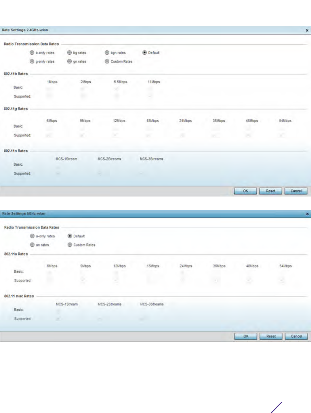
Wireless Configuration
Wireless Controller and Service Platform System Reference Guide 6 - 96
Figure 6-52 Advanced Rate Settings 2.4 GHz screen
Figure 6-53 Advanced Rate Settings 5 GHz screen
Define both minimum Basic and optimal Supported rates as required for the 802.11b rates, 802.11g rates and
802.11n rates supported by the 2.4 GHz band and 802.11a and 802.11n rates supported by the 5.0 GHz radio
band. These are the rates wireless client traffic is supported within this mesh point.
If supporting 802.11n, select a Supported MCS index. Set a MCS (modulation and coding scheme) in respect to
the radio’s channel width and guard interval. A MCS defines (based on RF channel conditions) an optimal
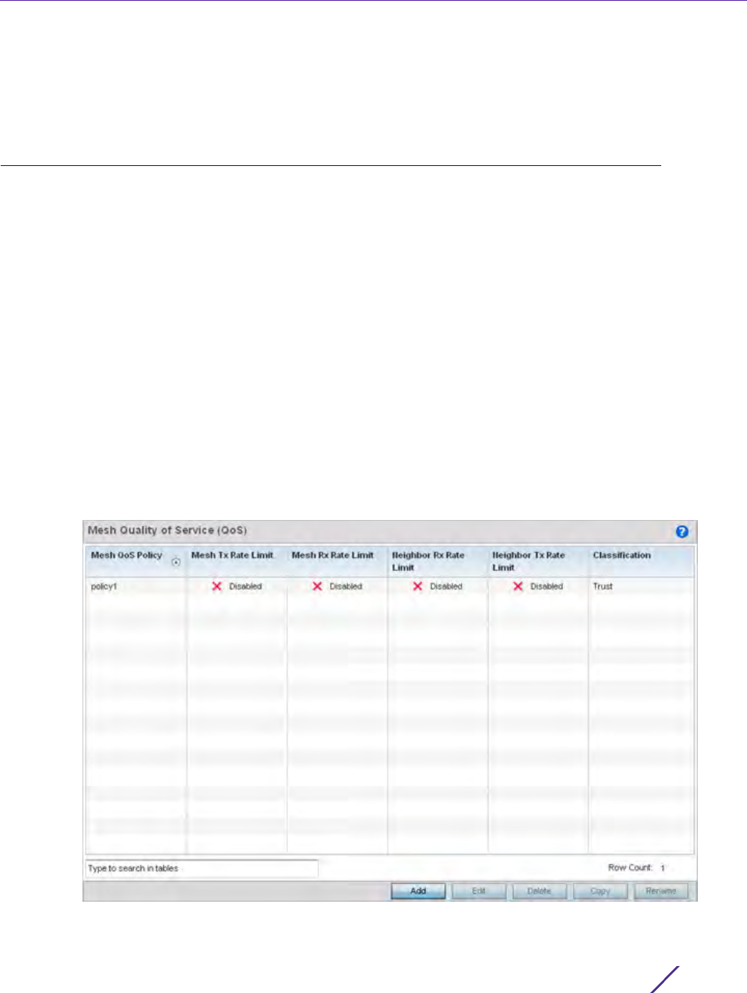
Wireless Configuration
Wireless Controller and Service Platform System Reference Guide 6 - 97
combination of 8 data rates, bonded channels, multiple spatial streams, different guard intervals and
modulation types. Clients can associate as long as they support basic MCS (as well as non-11n basic rates).
14 Select OK to save the changes made to the configuration. Select Reset to revert to the last saved configuration.
6.7 Mesh QoS Policy
Mesh Quality of Service (QoS) provides a data traffic prioritization scheme. QoS reduces congestion from excessive
traffic. If there is enough bandwidth for all users and applications (unlikely because excessive bandwidth comes at
a very high cost), then applying QoS has very little value. QoS provides policy enforcement for mission-critical
applications and/or users that have critical bandwidth requirements when bandwidth is shared by different users
and applications.
Mesh QoS helps ensure each mesh point on the mesh network receives a fair share of the overall bandwidth, either
equally or as per the proportion configured. Packets directed towards clients are classified into categories such as
video, voice and data. packets within each category are processed based on the weights defined for each mesh
point.
The Quality of Service screen displays a list of Mesh QoS policies available to mesh points. Each mesh QoS policy
can be selected to edit its properties. If none of the exiting Mesh QoS policies supports an ideal QoS configuration
for the intended data traffic of this mesh point, select the Add button to create new policy. Select an existing mesh
QoS policy and select Edit to change the properties of the Mesh QoS policy.
To define a Mesh QoS policy:
1Select
Configuration > Wireless > Mesh QoS Policy to display existing Mesh QoS policies.
Figure 6-54 Mesh QoS Policy screen

Wireless Configuration
Wireless Controller and Service Platform System Reference Guide 6 - 98
2 Refer to the following configuration data for existing Smart RF policies:
3 Select the Add button to define a new Mesh QoS policy, or select an existing Mesh QoS policy and select Edit
to modify its existing configuration. Existing QoS policies can be selected and deleted as needed. Optionally
Copy or Rename a policy as needed.
The Rate Limit screen displays by default for the new or modified QoS policy.
Excessive traffic can cause performance issues or bring down the network entirely. Excessive traffic can be
caused by numerous sources including network loops, faulty devices or malicious software such as a worm or
virus that has infected on one or more devices at the branch. Rate limiting limits the maximum rate sent to or
received from the wireless network (and mesh point) per neighbor. It prevents any single user from
overwhelming the wireless network. It can also provide differential service for service providers. An
administrator can set separate QoS rate limit configurations for data transmitted from the network and data
transmitted from a mesh point’s neighbor back to their associated Access Point radios and managing controller
or service platform.
Before defining rate limit thresholds for mesh point transmit and receive traffic, define the normal number of
ARP, broadcast, multicast and unknown unicast packets that typically transmit and receive from each
supported WMM access category. If thresholds are defined too low, normal network traffic (required by end-
user devices) is dropped, resulting in intermittent outages and performance problems.
A connected neighbor can also have QoS rate limit settings defined in both the transmit and receive direction.
Mesh QoS Policy Displays the administrator assigned name of each mesh QoS policy.
Mesh Tx Rate Limit Displays whether or not a Mesh Tx Rate Limit is enabled for each Mesh
QoS policy. When the rate limit is enabled a green check mark is
displayed, when it is disabled a red X is displayed.
Mesh Rx Rate Limit Displays whether or not a Mesh Rx Rate Limit is enabled for each Mesh
QoS policy. When the rate limit is enabled a green check mark is
displayed, when it is disabled a red X is displayed.
Neighbor Rx Rate Limit Displays whether or not a Neighbor Rx Rate Limit is enabled for each
Mesh QoS policy. When the rate limit is enabled a green check mark is
displayed, when it is disabled a red X is displayed.
Neighbor Tx Rate Limit Displays whether or not a Neighbor Tx Rate Limit is enabled for each
Mesh QoS policy. When the rate limit is enabled a green check mark is
displayed, when it is disabled a red X is displayed.
Classification Displays the forwarding QoS classification for each Mesh QoS policy.
Classification types are Trust, Voice, Video, Best Effort and Background.
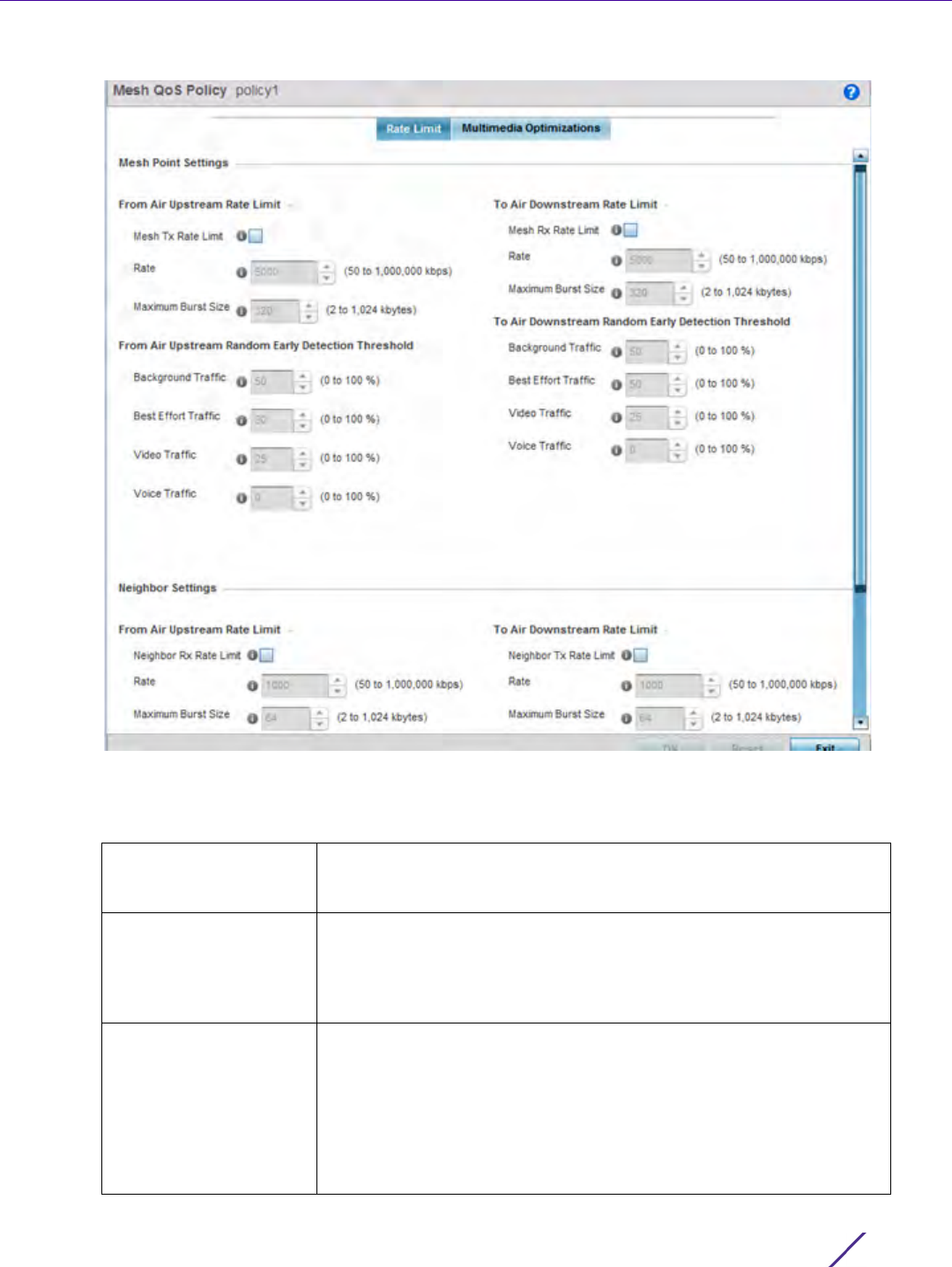
Wireless Configuration
Wireless Controller and Service Platform System Reference Guide 6 - 99
Figure 6-55 Mesh QoS Policy Rate Limit screen
4 Configure the following parameters in respect to the intended From Air Upstream Rate Limit, or traffic from the
controller to associated Access Point radios and their associated neighbor:
Mesh Tx Rate Limit Select the check box to enable rate limiting for all data received from
any mesh point in the mesh network. This feature is disabled by
default.
Rate Define a receive rate limit between 50 - 1,000,000 kbps. This limit
constitutes a threshold for the maximum the number of packets
transmitted or received over the mesh point (from all access
categories). Traffic that exceeds the defined rate is dropped and a log
message is generated. The default setting is 5000 kbps.
Maximum Burst Size Set a maximum burst size between 2 - 1024 kbytes. The smaller the
burst, the less likely the transmit packet transmission will result in
congestion for the mesh point’s client destinations. By trending the
typical number of ARP, broadcast, multicast and unknown unicast
packets over a period of time, the average rate for each access
category can be obtained. Once a baseline is obtained, administrators
should then add a 10% margin (minimally) to allow for traffic bursts at
the site. The default burst size is 320 kbytes.

Wireless Configuration
Wireless Controller and Service Platform System Reference Guide 6 - 100
5 Set the following From Air Upstream Random Early Detection Threshold settings for each access category. An
early random drop is done when a traffic stream falls below the set threshold.
6 Configure the following parameters in respect to the intended To Air Downstream Rate Limit, or traffic from
neighbors to associated Access Point radios and the controller or service platform:
Background Traffic Set a percentage value for background traffic in the transmit direction.
This is a percentage of the maximum burst size for low priority traffic.
Background traffic exceeding the defined threshold is dropped and a
log message is generated. Background traffic consumes the least
bandwidth of any access category, so this value can be set to a lower
value once a general transmit rate is known by the network
administrator (using a time trend analysis). The default threshold is
50%.
Best Effort Traffic Set a percentage value for best effort traffic in the transmit direction.
This is a percentage of the maximum burst size for normal priority
traffic. Best effort traffic exceeding the defined threshold is dropped
and a log message is generated. Best effort traffic consumes little
bandwidth, so this value can be set to a lower value once a general
transmit rate is known by the network administrator (using a time
trend analysis). The default threshold is 50%.
Video Traffic Set a percentage value for video traffic in the transmit direction. This is
a percentage of the maximum burst size for video traffic. Video traffic
exceeding the defined threshold is dropped and a log message is
generated. Video traffic consumes significant bandwidth, so this value
can be set to a higher value once a general transmit rate is known by
the network administrator (using a time trend analysis). The default
threshold is 25%.
Voice Traffic Set a percentage value for voice traffic in the transmit direction. This is
a percentage of the maximum burst size for voice traffic. Voice traffic
exceeding the defined threshold is dropped and a log message is
generated. Voice applications consume significant bandwidth, so this
value can be set to a higher value once a general upstream rate is
known by the network administrator (using a time trend analysis). The
default threshold is 0%.
Mesh Rx Rate Limit Select the check box to enable rate limiting for all data transmitted by
the device to any mesh point in the mesh. This feature is disabled by
default.
Rate Define an transmit rate limit between 50 - 1,000,000 kbps. This limit
constitutes a threshold for the maximum the number of packets
transmitted or received over the mesh point (from all access
categories). Traffic that exceeds the defined rate is dropped and a log
message is generated. The default setting is 5000 kbps.
Maximum Burst Size Set a maximum burst size between 2 - 1024 kbytes. The smaller the
burst, the less likely the receive packet transmission will result in
congestion for the mesh points wireless client destinations. By
trending the typical number of ARP, broadcast, multicast and unknown
unicast packets over a period of time, the average rate for each access
category can be obtained. Once a baseline is obtained, administrators
should then add a minimum of a 10% margin to allow for traffic bursts
at the site. The default burst size is 320 kbytes.

Wireless Configuration
Wireless Controller and Service Platform System Reference Guide 6 - 101
7 Set the following To Air Downstream Random Early Detection Threshold settings for each access category. An
early random drop occurs when the amount of tokens for a traffic stream falls below the set threshold.
8 Configure the following parameters in respect to the intended Neighbor Settings From Air Upstream Rate Limit:
Background Traffic Set a percentage value for background traffic in the receive direction.
This is a percentage of the maximum burst size for low priority traffic.
Background traffic exceeding the defined threshold is dropped and a
log message is generated. Background traffic consumes the least
bandwidth of any access category, so this value can be set to a lower
value once a general receive rate is known by the network
administrator (using a time trend analysis). The default threshold is
50%.
Best Effort Traffic Set a percentage value for best effort traffic in the receive direction.
This is a percentage of the maximum burst size for normal traffic. Best
effort traffic exceeding the defined threshold is dropped and a log
message is generated. Best effort traffic consumes little bandwidth, so
this value can be set to a lower value once a general receive rate is
known by the network administrator (using a time trend analysis). The
default threshold is 50%.
Video Traffic Set a percentage value for video traffic in the receive direction. This is
a percentage of the maximum burst size for video traffic. Video traffic
exceeding the defined threshold is dropped and a log message is
generated. Video traffic consumes significant bandwidth, so this value
can be set to a higher value once a general receive rate is known by
the network administrator (using a time trend analysis). The default
threshold is 25%.
Voice Traffic Set a percentage value for voice traffic in the receive direction. This is
a percentage of the maximum burst size for voice traffic. Voice traffic
exceeding the defined threshold is dropped and a log message is
generated. Voice applications consume significant bandwidth, so this
value can be set to a higher value once a general transmit rate is
known by the network administrator (using a time trend analysis). The
default threshold is 0%. 0% means no early random drops will occur.
Neighbor Rx Rate Limit Select the radio button to enable rate limiting for data transmitted
from the client to its associated Access Point radio and connected
controller or service platform. Enabling this option does not invoke
client rate limiting for data traffic in the receive direction. This feature
is disabled by default.
Rate Define an transmit rate limit between 50 - 1,000,000 kbps. This limit
constitutes a threshold for the maximum the number of packets
transmitted or received (from all access categories). Traffic that
exceeds the defined rate is dropped by the client and a log message is
generated. The default rate is 1,000 kbps.
Maximum Burst Size Set a maximum burst size between 2 - 1024 kbytes. The smaller the
burst, the less likely the transmit packet transmission will result in
congestion for the wireless client. The default burst size is 64 kbytes.

Wireless Configuration
Wireless Controller and Service Platform System Reference Guide 6 - 102
9 Set the following Neighbor Settings From Air Upstream Random Early Detection Threshold for each access
category:
10 Configure the following parameters in respect to the intended Neighbor To Air Downstream Rate Limit, or traffic
from a controller or service platform to associated Access Point radios and the wireless client:
11 Set the following To Air Downstream Random Early Detection settings for each access category:
Background Traffic Set a percentage value for background traffic in the transmit direction.
This is a percentage of the maximum burst size for low priority traffic.
Background traffic exceeding the defined threshold is dropped by the
client and a log message is generated. The default threshold is 50%.
Best Effort Traffic Set a percentage value for best effort traffic in the transmit direction.
This is a percentage of the maximum burst size for normal traffic. Best
effort traffic exceeding the defined threshold is dropped by the client
and a log message is generated. The default threshold is 50%.
Video Traffic Set a percentage value for video traffic in the transmit direction. This is
a percentage of the maximum burst size for video traffic. Video traffic
exceeding the defined threshold is dropped by the client and a log
message is generated. The default threshold is 25%.
Voice Traffic Set a percentage value for voice traffic in the receive direction. This is
a percentage of the maximum burst size for voice traffic. Voice traffic
exceeding the defined threshold is dropped by the client and a log
message is generated. The default threshold is 0%.0% implies no early
random drops will occur.
Neighbor Tx Rate Limit Select the radio button to enable rate limiting for data transmitted
from connected wireless clients. Enabling this option does not invoke
rate limiting for data traffic in the transmit direction. This feature is
disabled by default.
Rate Define a receive rate limit between 50 - 1,000,000 kbps.This limit
constitutes a threshold for the maximum the number of packets
transmitted or received by the client. Traffic that exceeds the defined
rate is dropped and a log message is generated. The default rate is
1,000 kbytes.
Maximum Burst Size Set a maximum burst size between 2 - 64 kbytes. The smaller the
burst, the less likely the receive packet transmission will result in
congestion for the wireless client. The default burst size is 64 kbytes.
Background Traffic Set a percentage value for background traffic in the receive direction.
This is a percentage of the maximum burst size for low priority traffic.
Background traffic exceeding the defined threshold is dropped by the
client and a log message is generated. The default is 50%.
Best Effort Traffic Set a percentage value for best effort traffic in the receive direction.
This is a percentage of the maximum burst size for normal traffic. Best
effort traffic exceeding the defined threshold is dropped by the client
and a log message is generated. The default is 50%.
Video Traffic Set a percentage value for video traffic in the receive direction. This is
a percentage of the maximum burst size for video traffic. Video traffic
exceeding the defined threshold is dropped by the client and a log
message is generated. The default is 25%.
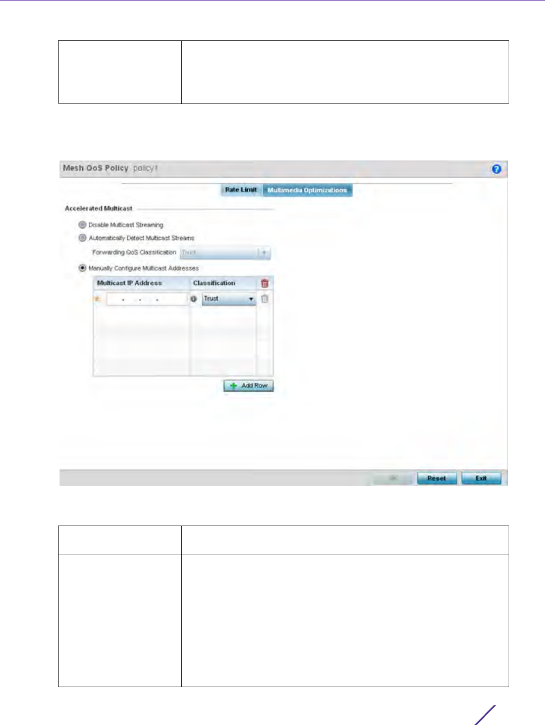
Wireless Configuration
Wireless Controller and Service Platform System Reference Guide 6 - 103
12 Select OK when completed to update this Mesh QoS rate limit settings. Select Reset to revert the screen back
to its last saved configuration.
13 Select the Multimedia Optimizations tab.
Figure 6-56 Mesh QoS Policy Multimedia Optimizations screen
14 Set the following Accelerated Multicast settings:
Voice Traffic Set a percentage value for voice traffic in the receive direction. This is
a percentage of the maximum burst size for voice traffic. Voice traffic
exceeding the defined threshold is dropped by the client and a log
message is generated. The default threshold is 0%.0% means no early
random drops occur.
Disable Multicast
Streaming
Select this option to disable all Multicast Streaming on the mesh point.
Automatically Detect
Multicast Streams
Select this option to allow the administrator to have multicast packets
that are being bridged converted to unicast to provide better overall
airtime utilization and performance. The administrator can either have
the system automatically detect multicast streams and convert all
detected multicast streams to unicast, or specify which multicast
streams are to be converted to unicast. When the stream is converted
and being queued up for transmission, there are a number of
classification mechanisms that can be applied to the stream and the
administrator can select what type of classification they would want.
Classification types are Trust, Voice, Video, Best Effort, and
Background.
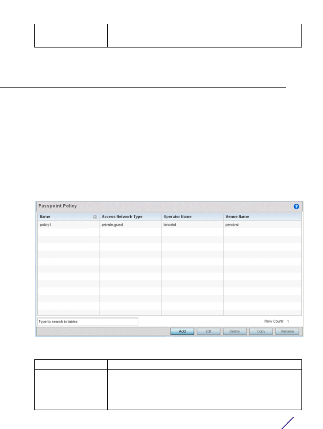
Wireless Configuration
Wireless Controller and Service Platform System Reference Guide 6 - 104
15 Select OK when completed to update the Mesh Multimedia Optimizations settings. Select Reset to revert the
screen back to its last saved configuration.
6.8 Passpoint Policy
A passpoint policy provides an interoperable platform for streamlining Wi-Fi access to Access Points deployed as
public hotspots. Passpoint is supported across a wide range of wireless network deployment scenarios and client
devices.
Passpoint makes connecting to Wi-Fi networks easier by authenticating the user with an account based on an
existing relationship, such as the user's mobile carrier or broadband ISP.
The Passpoint Policy screen displays a list of passpoint polices for network hotspots. Each passpoint policy can be
selected to edit its properties. If no exiting passpoint policies supports the required deployment, select Add to
create a new policy.
To administrate and manage existing passpoint policies:
1Select
Configuration > Wireless > Passpoint Policy to display existing policies.
Figure 6-57 Passpoint Policy screen
2 Refer to the following configuration data for existing passpoint policies:
Manually Configure
Multicast Addresses
Select + Add Row and specify a list of multicast addresses and
classifications. Packets are accelerated when the destination addresses
matches.
Name Displays the administrator assigned name of each passpoint policy.
Access Network Type Displays the network access permissions the administrator has set for
the passpoint policy.
Operator Name Displays the unique name assigned to the administrator or operator
responsible for the configuration and operation of the Access Point
managed hotspot.
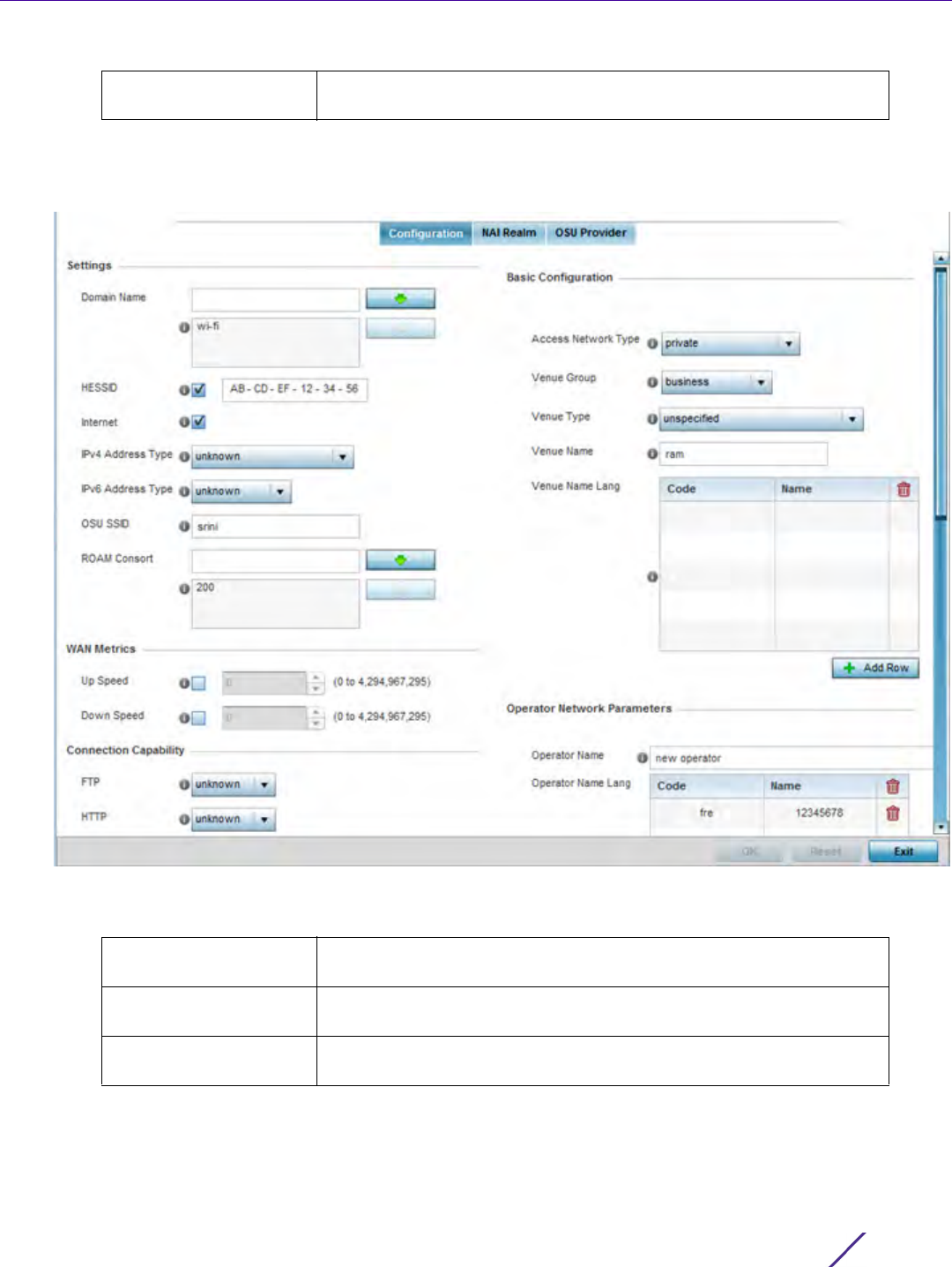
Wireless Configuration
Wireless Controller and Service Platform System Reference Guide 6 - 105
3Select Add to define a new passpoint policy, or select an existing policy and select Edit to modify its
configuration. Existing policies can be selected and deleted, copied, or renamed as needed. Optionally Copy or
Rename a policy as needed.
Figure 6-58 Passpoint Policy - Configuration screen
4 Refer to the following Settings to define an Internet connection medium for the passpoint policy:
Venue Name Displays the administrator assigned name of the venue (or physical
location) of the deployed Access Point hotspot.
Domain Name Optionally add a 255 character maximum domain name to the pool
available to the passpoint policy.
HESSID Select this option to apply a homogenous ESS ID. Leaving this option
blank applies the BSSID instead. This option is disabled by default.
Internet Select this option to enable Internet access to users of the passpoint
hotspot. Internet access is enabled by default.

Wireless Configuration
Wireless Controller and Service Platform System Reference Guide 6 - 106
5 Set the following WAN Metrics for upstream and downstream bandwidth:
6 Set the following Connection Capability for passpoint policy’s FTP, HTTP, ICMP, IPSec VPN, PPTP VPN, SIP, SSH
and TLS VPN interfaces:
7 Use the drop-down menu to define these interfaces as open, closed or unknown for this passpoint policy
configuration. Disabling unused interfaces is recommended to close unnecessary security holes.
8Select
+ Add Row to set a Connection Capability Variable to make specific virtual ports open or closed for Wi-Fi
connection attempts, set rules for how the user is to connect with routing preference using this passpoint
policy.
9Select
+ Add Row and set a Network Authentication Type to select how Wi-Fi connection attempts are
authenticated and validated using a dedicated redirection URL resource.
10 Refer to the Basic Configuration field to set the following:
IPv4 Address Type Use the drop-down menu to select the IPv4 formatted address type
for this passpoint policy. IPv4 is a connectionless protocol operating on
a best effort delivery model. IPv4 does not guarantee delivery or
assures proper sequencing or avoidance of duplicate delivery (unlike
TCP). Options include, not available, public, port-restricted, port-
restricted-double-nat, single-nat, double-nat, port-restricted-single-nat
and unknown.
IPv6 Address Type Use the drop-down menu to select the IPv4 formatted address type
for this passpoint policy. IPv6 is the latest revision of the Internet
Protocol (IP) designed to replace IPv4. IPV6 provides enhanced
identification and location information for computers on networks
routing traffic across the Internet. Options include, available,
unavailable and unknown.
OSU SSID Optionally define a 32 character maximum sign-on ID that must be
correctly provided to access the passpoint policy’s hotspot resources.
ROAM Consort Provide a 0 - 255 character roaming consortium number. A roaming
consort ID is sent as roaming consortium information in a hotspot
query response.
Up Speed Enable this option to estimate the maximum upstream bandwidth from
0 - 4,294,967,295 Kbps.
Down Speed Enable this option to estimate the maximum downstream bandwidth
from 0 - 4,294,967,295 Kbps.
Access Network Type Use the drop-down menu to select the network access method for this
passpoint policy. Access network types include:
private – General access to a private network hotspot (default setting)
private-guest – Access to a private network hotspot with guest
services
chargeable-public – Access to a public hotspot with billable services
personal-device – Access to a hotspot for personal devices such as
wireless routers
emergency services – Dedicated network hotspot access for
emergency services only

Wireless Configuration
Wireless Controller and Service Platform System Reference Guide 6 - 107
11 Refer to the Operator Network Parameters field to define the following:
12 Select OK when completed to update the passpoint policy settings. Select Reset to revert the screen back to
the last saved configuration.
13 Select the NAI Realm tab.
The Network Access Identifier (NAI) is the user identity submitted by the hotspot requesting client during
authentication. The standard syntax is user@realm. NAI is frequently used when roaming, to identify the user
and assist in routing an authentication request to the user's authentication server. The realm name is often the
domain name of the service provider.
The NAI realm screen displays those realms created thus far for utilization with a passpoint policy.
Venue Group Passpoint is supported across a wide range of wireless network
deployment scenarios and client devices. Select the group type best
suited to the majority of hotspot requestors utilizing the passpoint
policy’s unique configuration.
Venue Type Select the venue type best suited to the actual location passpoint
requestors are located. If an adequate option cannot be applied, a
numeric venue type can be utilized.
Venue Name Enter the Venue Name and address. The operator can configure an
Access Point to describe the location of the hotspot. This information
typically includes the name and address of the deployment location
where the hotspot is located. Enter the name and address configured
for the Access Point hotspot. The name cannot exceed 252 characters.
Venue Name Lang Hotspot operators can list venue names in multiple languages. Select
the + Add Row button to add venue name languages. Enter the two or
three character ISO-14962-1997 encoded string that defines the
language used in the Code field. Enter the name of the venue in the
Name field. The name cannot exceed 252 characters.
Operator Name Provide the unique name (in English) of the administrator or operator
responsible for the configuration and management or the hotspot. The
name cannot exceed 64 characters.
Operator Name Lang Operator names can be listed in multiple languages. Select + Add Row
to add operator name languages. Enter the two or three character
ISO-14962-1997 encoded string defining the language used in the Code
field. Enter the name of the operator in the Name field. The name
cannot exceed 252 characters.
PLMNID Operators providing mobile and Wi-Fi hotspot services have a unique
Public Land Mobile Network (PLMN) ID. Select the + Add Row button
to add PLMN information for operators responsible for the
configuration and operation of the hotspot. Provide a Description for
the PLMN not exceeding 64 characters.
Enter a three digit Mobile Country Code (MCC) and two digit Mobile
Network Code (MNC) for the PLMN ID. The MCC identifies the region
and country where the hotspot is deployed. The MNC identifies the
operator responsible for the configuration and management of the
hotspot by PLMN ID and country. Both the MCC and MNC fields are
mandatory.
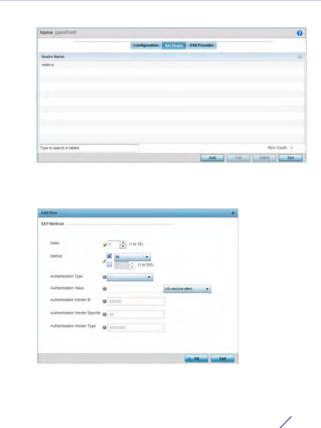
Wireless Configuration
Wireless Controller and Service Platform System Reference Guide 6 - 108
Figure 6-59 Passpoint Policy - NAI Realm screen
Either select Add to create a new NAI realm configuration for passpoint hotspot utilization, Edit to modify the
attributes on an existing selected configuration or Delete to remove a selected configuration from those
available. Provide a Realm Name or names (32 characters maximum) delimited by a semi colon. Select + Add
Row to create a EAP Method configuration for the NAI realm.
Figure 6-60 Passpoint Policy - NAI Realm Add/Edit screen

Wireless Configuration
Wireless Controller and Service Platform System Reference Guide 6 - 109
14 Set the following EAP Method attributes to secure the NAI realm used by the passpoint policy:
15 Select OK to save the updates to the NAI realm.
16 Select the OSU Provider tab.
WiNG managed clients can use Online Sign-Up (OSU) for registration and credential provisioning to obtain
hotspot network access. Service providers have an OSU AAA server and certificate authority (CA). For a client
and hotspot to trust one another, the OSU server holds a certificate signed by a CA whose root certificate is
issued by a CA authorized by the Wi-Fi Alliance, and CA certificates are installed on the client device. A CA
performs four functions:
• Issues certificates (creates and signs)
• Maintains certificate status information and issues certificate revocation lists (CRLs)
• Publishes current (non-expired) certificates and CRLs
• Maintains status archives for the expired or revoked certificates it has issued
Passpoint certificates are governed by the Hotspot 2.0 OSU Certificate Policy Specification. An OSU server
certificate should be obtained from any of the CAs authorized by the Wi-Fi Alliance. Once an OSU provider is
selected, the client connects to the OSU WLAN. It then triggers an HTTPS connection to the OSU server, which
was received with the OSU providers list. The client validates the server certificate to ensure it's a trusted OSU
server. The client is prompted to complete an online registration through their browser. When the client has a
valid credential for the hotspot 2.0 WLAN, it disassociates from the OSU WLAN and connects to the hotspot
2.0 WLAN.
The OSU Provider screen displays those provider configurations created thus far for utilization with a passpoint
policy.
Index Select an EAP instance index from 1 - 10 to apply to this hotspot’s EAP
credential exchange and verification session. NAIs are often user
identifiers in the EAP authentication protocol.
Method Set an EAP method for the NAI realm. Options include identity, otp,
gtc, rsa-public-key, tls, sim, ttls, peap, ms-auth, ms-authv2, fast, psk
and ikev2.
Authentication Type Use the drop-menu to specify the EAP method authentication type.
Options include expanded-eap, non-eap-inner, inner-eap, expanded-
inner-eap, credential, tunn-eap-credential and vendor.
Authentication Value If setting the authentication type to either non-eap-inner, inner-eap,
credential or tunnel-eap-credential define an authentication value that
must be shared with the EAP credential validation server resource.
Authentication Vendor
ID
If the authentication type is set to either, expanded-eap or expanded-
inner-eap, set a 6 character authentication vendor ID that must match
the one utilized by the EAP server resource.
Authentication Vendor
Specific
If required, add 2 - 510 character vendor specific authentication data
required for the selected authentication type. Enter the value is an a-
FA -F0-9 format.
Authentication Vendor
Type
Set a 8 character authentication vendor type used exclusively for the
expanded-eap or expanded-inner-eap authentication types.
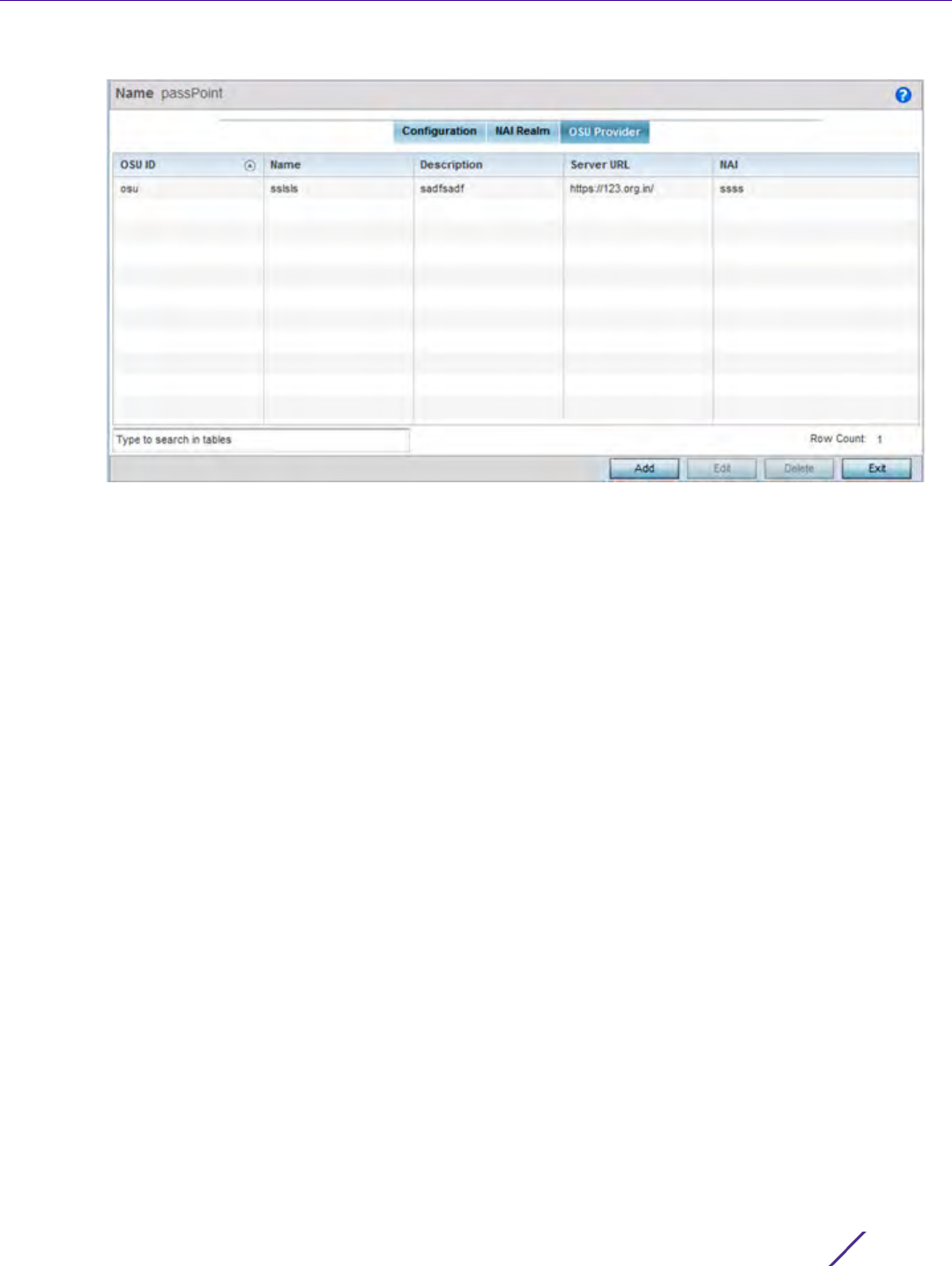
Wireless Configuration
Wireless Controller and Service Platform System Reference Guide 6 - 110
Figure 6-61 Passpoint Policy - OSU Provider screen
17 Either select Add to create a new OSU provider configuration for passpoint hotspot utilization, Edit to modify
the attributes on an existing selected configuration or Delete to remove a selected configuration from those
available.
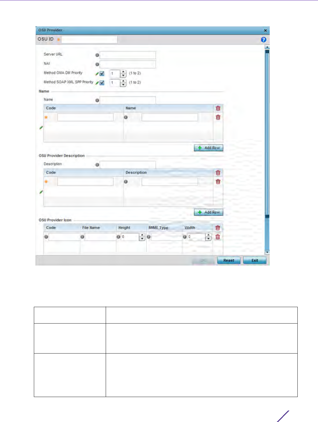
Wireless Configuration
Wireless Controller and Service Platform System Reference Guide 6 - 111
Figure 6-62 Passpoint Policy - OSU Provider Add/Edit screen
18 If creating a new OSU provider configuration, provide it a 32 character maximum OSU ID serving as an online
sign up identifier.
19 Set the following attributes to secure the NAI realm used by the passpoint policy:
Server URL Provide a 255 character maximum sign up server URL for the OSU
provider.
NAI Enter a 255 character maximum Network Access Identifier (NAI) to
identify the user and assist in routing an authentication request to the
authentication server. The realm name is often the domain name of the
service provider
Method OMA DM
Priority
Select this option to provide open mobile alliance (OMA) device
management priority. The OMA is a standards body developing open
standards for mobile clients. OMA is relevant to service providers
working across countries (with different languages), operators and
mobile terminals. Adherence to OMA is strictly voluntary. Use the drop-
menu to specify the priority as 1 or 2.

Wireless Configuration
Wireless Controller and Service Platform System Reference Guide 6 - 112
20 Refer to the Name field to optionally set a 252 character English language sign up name, then provide a 3
character maximum ISO-639 language Code to apply the sign up name in a language other then English. Apply
a 252 character maximum hexadecimal online sign up Name to encode in the ISO-639 language code applied to
the sign up name.
21 Refer to the OSU Provider Description field to set an online sign up description in a language other then
English.
Select + Add Row and provide a 3 character maximum ISO-639 language Code to apply the sign up name in a
language other then English. Apply a 252 character maximum hexadecimal online sign up Description to
encode in the ISO-639 language code applied to the sign up name.
22 Optionally provide an OSU Provider Icon by selecting + Add Row. Apply the following configuration attributes to
the icon.
23 Select OK to save the updates to the OSU provider configuration. Select Reset to revert to the last saved
configuration.
6.9 Sensor Policy
In addition to WIPS support, sensor functionality has now been added for Extreme Networks’ MPact locationing
system. The MPact system for Wi-Fi locationing includes WiNG controllers and Access Points functioning as
sensors. Within the MPact architecture, sensors scan for RSSI data on an administrator defined interval and send to
a dedicated MPact Server resource, as opposed to an ADSP server. The MPact Server collects the RSSI data from
WiNG sensor devices, and calculates the location of Wi-Fi devices for MPact administrators.
To administrate and manage existing sensor policies:
Method SOAP XML SPP
Priority
Select this option to apply a SOAP-XML subscription provisioning
protocol priority of either 1 or 2. The simple object access protocol
(SOAP) is a protocol for exchanging structured information in Web
services. SOAP uses XML as its message format, and relies on other
application layer protocols, like HTTP or SMTP for message negotiation
and transmission.
Code Enter a 3 character maximum ISO-639 language Code to define the
language used in the OSU provider icon.
File Name Provide a 255 character maximum icon name and directory path
location to the icon file.
Height Provide the icon height size in pixels from 0 - 65,535. The default
setting is 0.
MIME Type Set the icon MIME file type from 0 - 64. The MIME associates filename
extensions with a MIME type. A MIME enables a fallback on an
extension and are frequently used by Web servers.
Width Provide the icon width size in pixels from 0 - 65,535. The default
setting is 0.
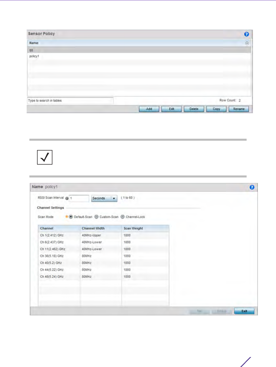
Wireless Configuration
Wireless Controller and Service Platform System Reference Guide 6 - 113
1Select Configuration > Wireless > Sensor Policy to display existing policies.
Figure 6-63 Sensor Policy screen
2Select Add to define a new sensor policy, or select an existing policy and select Edit to modify its configuration.
Existing sensor policies can be selected and deleted, copied, or renamed as needed.
Figure 6-64 Sensor Policy - Configuration screen
3Select Add to define a new sensor policy, or select an existing policy and select Edit to modify its configuration.
Existing sensor policies can be selected and deleted, copied, or renamed as needed.
NOTE: If a dedicated sensor is utilized with WIPS for rogue detection, any sensor
policy selected from the Sensor Policy drop-down menu is discarded and not
utilized by the sensor. To avoid this situation, use ADSP channel settings exclusively
to configure the sensor and not the WiNG interface.

Wireless Configuration
Wireless Controller and Service Platform System Reference Guide 6 - 114
4 If creating a new sensor policy, assign it a Name up to 32 characters. No character spaces are permitted within
the name. Define a name unique to the policy’s channel and scan mode configuration to help differentiate it
from other policies. If adding a new sensor policy, the Name must be provided and Continue selected to enable
the remaining configuration parameters.
Use the RSSI Scan Interval drop-down menu to set a scan interval from 1 - 60 seconds. This is the scan period
dedicated sensors (Access Point radios) utilize for RSSI (signal strength) assessments. Once obtained, the
sensor sends the RSSI data to a specified MPact server resource (not an ADSP server) for the calculation of Wi-
Fi device locations. The default is 1 second.
5 Set the following Scan Mode values depending on whether Default-Scan, Custom Scan or Channel Lock has
been selected as the mode of scan operation:
6Select
OK when completed to update the sensor policy settings. Select Reset to revert the screen back to the
last saved configuration.
Channel Default-Scan - The list of available scan channels is fixed and defaulted
in a spread pattern of 1, 6, 11, 36, 40, 44 and 48. No alternations to this
channel pattern are available to the administrator.
Custom-Scan - A list of unique channels in the 2.4, 4.9, 5 and 6 GHz
band can be collectively or individually enabled for customized
channel scans and RSSI reporting.
Channel-Lock - Once selected, the existing Channel, Channel Width
and Scan Weight table items are replaced by a Lock Frequency drop-
down menu. Use this menu to lock the RSSI scan to one specific
channel.
Channel Width Default-Scan - Each channel’s width is fixed and defaulted to either
40MHz-Upper (Ch 1), 40MHz-Lower (Ch 6 and CH 11) or 80MHz (CH
36, CH 40, CH 44 and CH 48).
Custom-Scan - When custom channels are selected for RSSI scans,
each selected channel can have its own width defined. Numerous
channels have their width fixed at 20MHz, 802.11a radios support 20
and 40 MHz channel widths.
Channel-Lock - If a specific channel is selected and locked for an RSSI
scan, there’s no ability to refine the width between adjacent channels,
as only one channel is locked.
Scan Weight Default-Scan - Each default channel’s scan is of equal duration (1000)
within the defined RSSI scan interval. No one channel receives scan
priority within the defined RSSI scan interval.
Custom-Scan - Each selected channel can have its weight prioritized in
respect to the amount of time a scan is permitted within the defined
RSSI scan interval.
Channel-Lock - If a specific channel is selected and locked for an RSSI
scan, there’s no ability to refine the scan weightage in respect to all
the remaining unlocked channels.

7 - 1
Wireless Controller and Service Platform System Reference Guide
7
Network Configuration
Controllers, service platforms and Access Points allow packet routing customizations and unique network
resources for deployment specific routing configurations.
For more information on the options available, refer to the following:
•Policy Based Routing
•L2TP V3 Configuration
•Crypto CMP Policy
•AAA Policy
•AAA TACACS Policy
•IPv6 Router Advertisement Policy
•BGP
•Alias
•Application Policy
•Application
•Application Group
•Schedule Policy
•URL Filtering
•Web Filtering
•EX3500 QoS Class
•EX3500 QoS Policy Map
•Network Deployment Considerations
7.1 Policy Based Routing
Define a policy based routing (PBR) configuration to direct packets to selective paths. PBR can optionally mark
traffic for preferential services. PBR minimally provides the following:
• A means to use source address, protocol, application and traffic class as traffic routing criteria
• The ability to load balance multiple WAN uplinks
• A means to selectively mark traffic for QoS optimization
Since PBR is applied to incoming routed packets, a route-map is created containing a set of filters and associated
actions. Based on the actions defined in the route-map, packets are forwarded to the next relevant hop. Route-
maps are configurable under a global policy called routing-policy, and applied to profiles and devices.
Route-maps contain a set of filters which select traffic (match clauses) and associated actions (set clauses) for
routing. A routemap consists of multiple entries, each carrying a precedence value. An incoming packet is matched
against the route-map with the highest precedence (lowest numerical value). If it matches, the routing decision is
based on this route-map. If the packet does not match the route-map, the route-map entry with next highest
precedence is matched. If the incoming packet does not match any of the route-map entries, it’s subjected to
typical destination based routing. Each route-map entry can optionally enable/disable logging.
The following criteria can optionally be used as traffic selection segregation criteria:
•IP Access List - A typical IP ACL can be used for traffic permissions. The mark and log actions in ACL rules
however are neglected. Route-map entries have separate logging. Only one ACL can be configured per route
map entry.

Network Configuration
Wireless Controller and Service Platform System Reference Guide 7 - 2
•IP DSCP - Packet filtering can be performed by traffic class, as determined from the IP DSCP field. One DSCP
value is configurable per route map entry. If IP ACLs on a WLAN, ports or SVI mark the packet, the new/
marked DSCP value is used for matching.
•Incoming WLAN - Packets can be filtered by the incoming WLAN. There are two ways to match the WLAN:
- If the device doing policy based routing has an onboard radio and a packet is received on a local WLAN, then
this WLAN is used for selection.
- If the device doing policy based routing does not have an onboard radio and a packet is received from an
extended VLAN, then the device which received the packet passes the WLAN information in the MINT packet
for the PBR router to use as match criteria.
•Client role - The client role can be used as match criteria, similar to a WLAN. Each device has to agree on a
unique identifier for role definition and pass the same MINT tunneled packets.
•Incoming SVI - A source IP address qualifier in an ACL typically satisfies filter requirements. But if the host
originating the packet is multiple hops away, the incoming SVI can be used as match criteria. In this context
the SVI refers to the device interface performing policy based routing, and not the originating connected
device.
Each route map entry has a set of match and set (action) clauses. ACL rules configured under route map entries
merge to create a single ACL. Route map precedence values determine the prioritization of the rules in this
merged ACL. An IP DSCP value is also added to the ACL rules.
Set (or action) clauses determine the routing function when a packet satisfies match criteria. If no set clauses are
defined, the default is to fallback to destination based routing for packets satisfying the match criteria. If no set
clause is configured and fallback to destination based routing is disabled, then the packet is dropped. The
following can be defined within set clauses:
•Next hop - The IP address of the next hop or the outgoing interface through which the packet should be
routed. Up to two next hops can be specified. The outgoing interface should be a PPP, a tunnel interface or a
SVI which has DHCP client configured. The first reachable hop should be used, but if all the next hops aren’t
reachable, typical destination based route lookup is performed.
•Default next hop - If a packet subjected to PBR does not have an explicit route to the destination, the
configured default next hop is used. This can be either the IP address of the next hop or the outgoing interface.
Only one default next hop can be defined. The difference between the next hop and the default next-hop is in
case of former, PBR occurs first, then destination based routing. In case of the latter, the order is reversed. With
both cases:
a If a defined next hop is reachable, it’s used. If fallback is configured refer to (b).
b Do normal destination based route lookup. If a next hop is found its used, if not refer to (c).
c If default next hop is configured and reachable, it’s used. If not, drop the packet.
•Fallback - Fallback to destination based routing if none of the configured next hops are reachable (or not
configured). This is enabled by default.
•Mark IP DSCP - Set IP DSCP bits for QoS using an ACL. The mark action of the route maps takes precedence
over the mark action of an ACL.
To define a PBR configuration:
1 Select the Configuration tab from the Web UI.
2Select
Network.
NOTE: A packet should optimally satisfy all the match criteria, if no match clause is
defined in a route-map, it would match everything. Packets not conforming to any
of the match clauses are subjected to normal destination based routing.