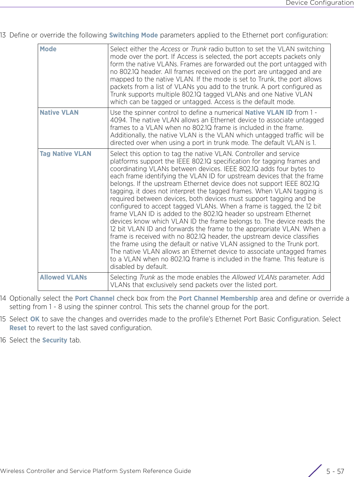
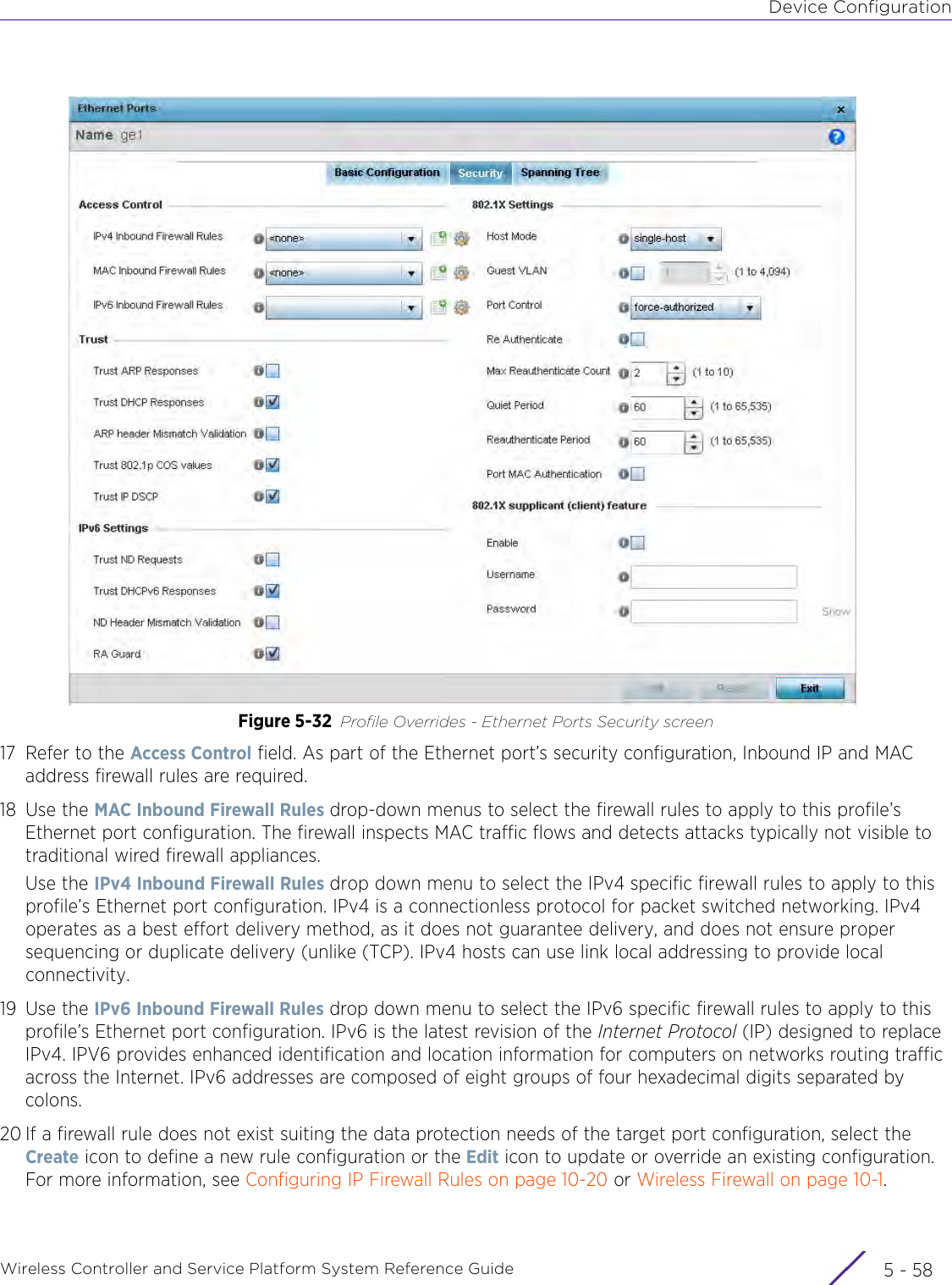
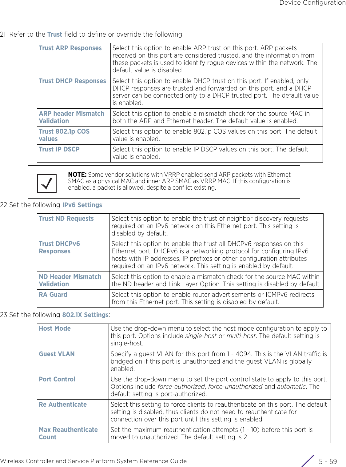
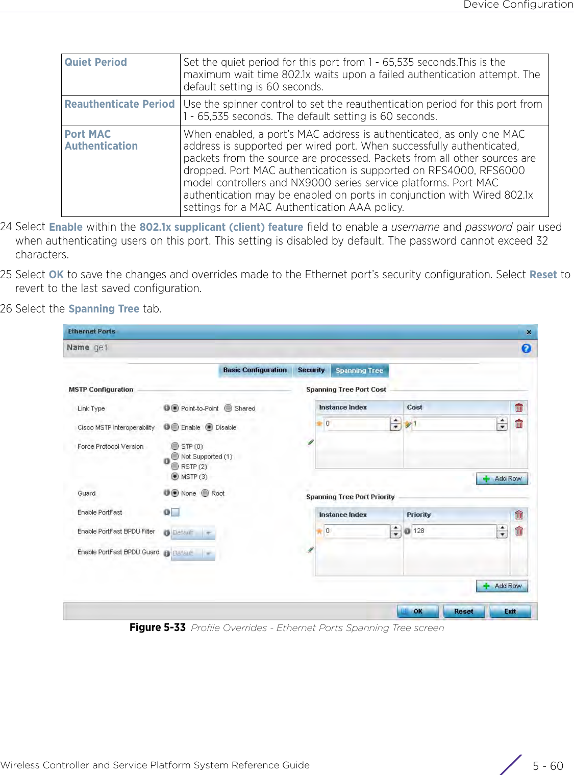
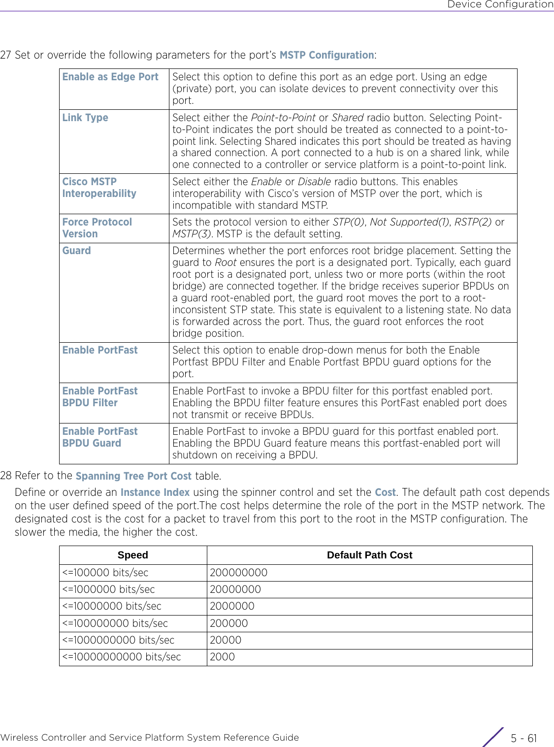
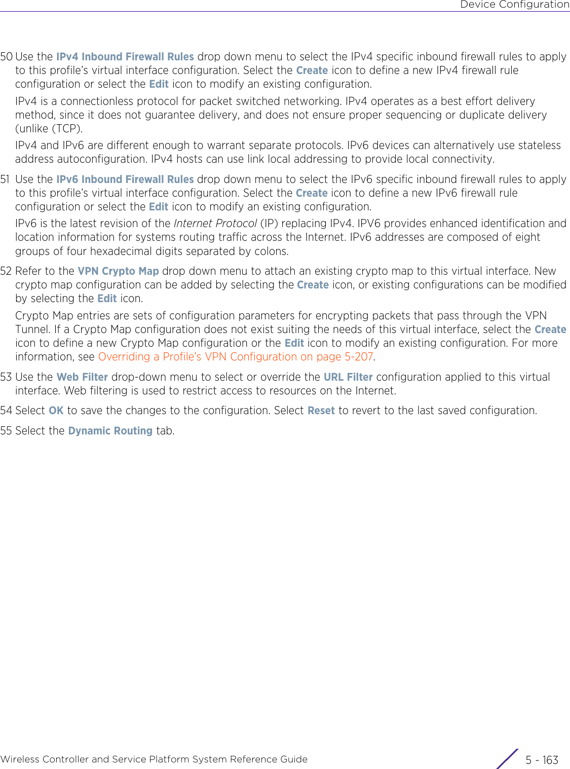
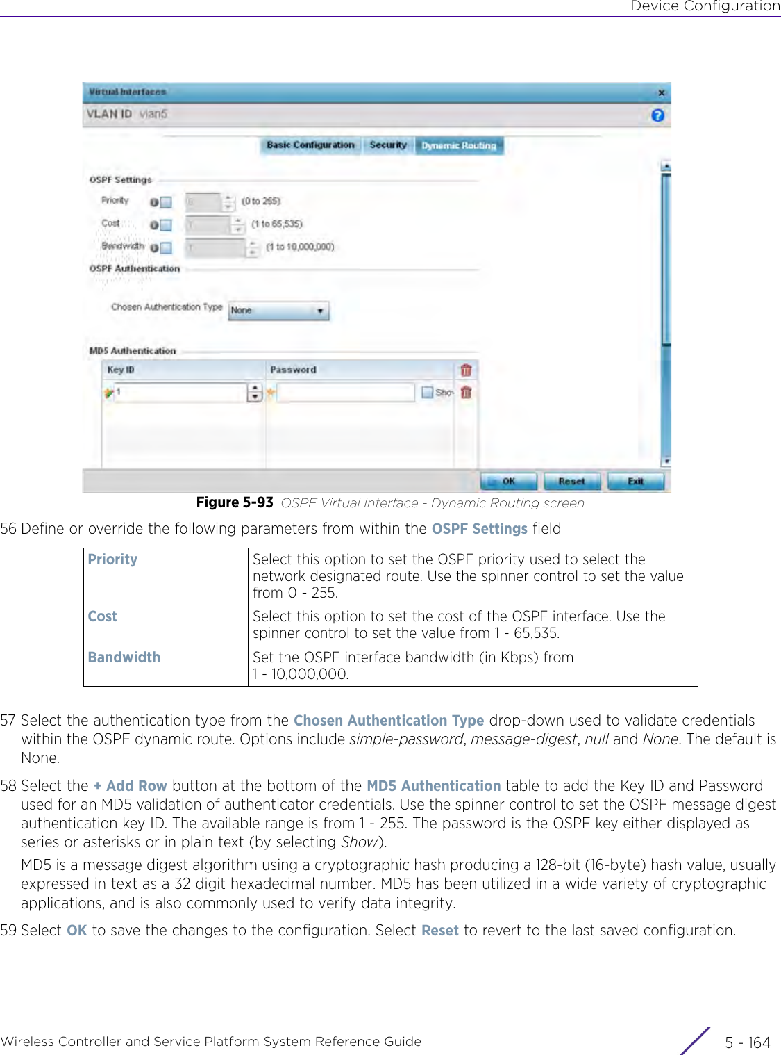
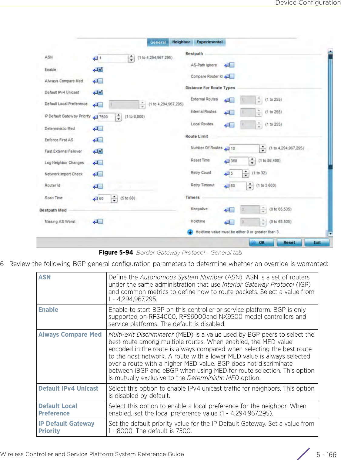
Extreme Networks AP3917E Wireless 802.11 a/ac+b/g/n Access Point User Manual WiNG 5 9 1 System Reference Guide Part 1
Extreme Networks, Inc. Wireless 802.11 a/ac+b/g/n Access Point WiNG 5 9 1 System Reference Guide Part 1
Contents
- 1. User Manual-AP3917e
- 2. User Manual-AP7662
- 3. User Manual-AP3917e R1
- 4. User Manual-AP7662 R1
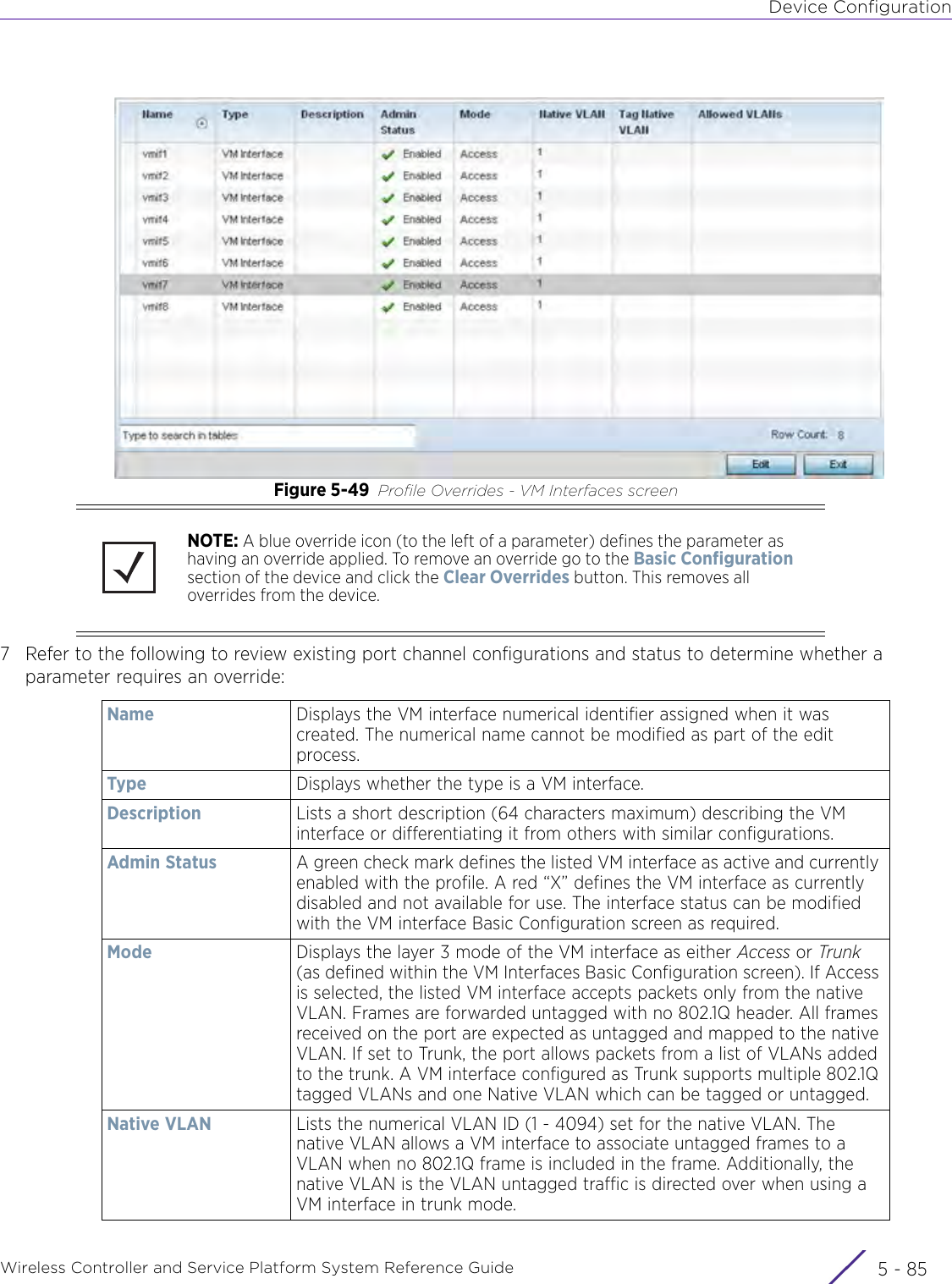
- 5. WiNG 5.9.1 System Reference Guide Part 1
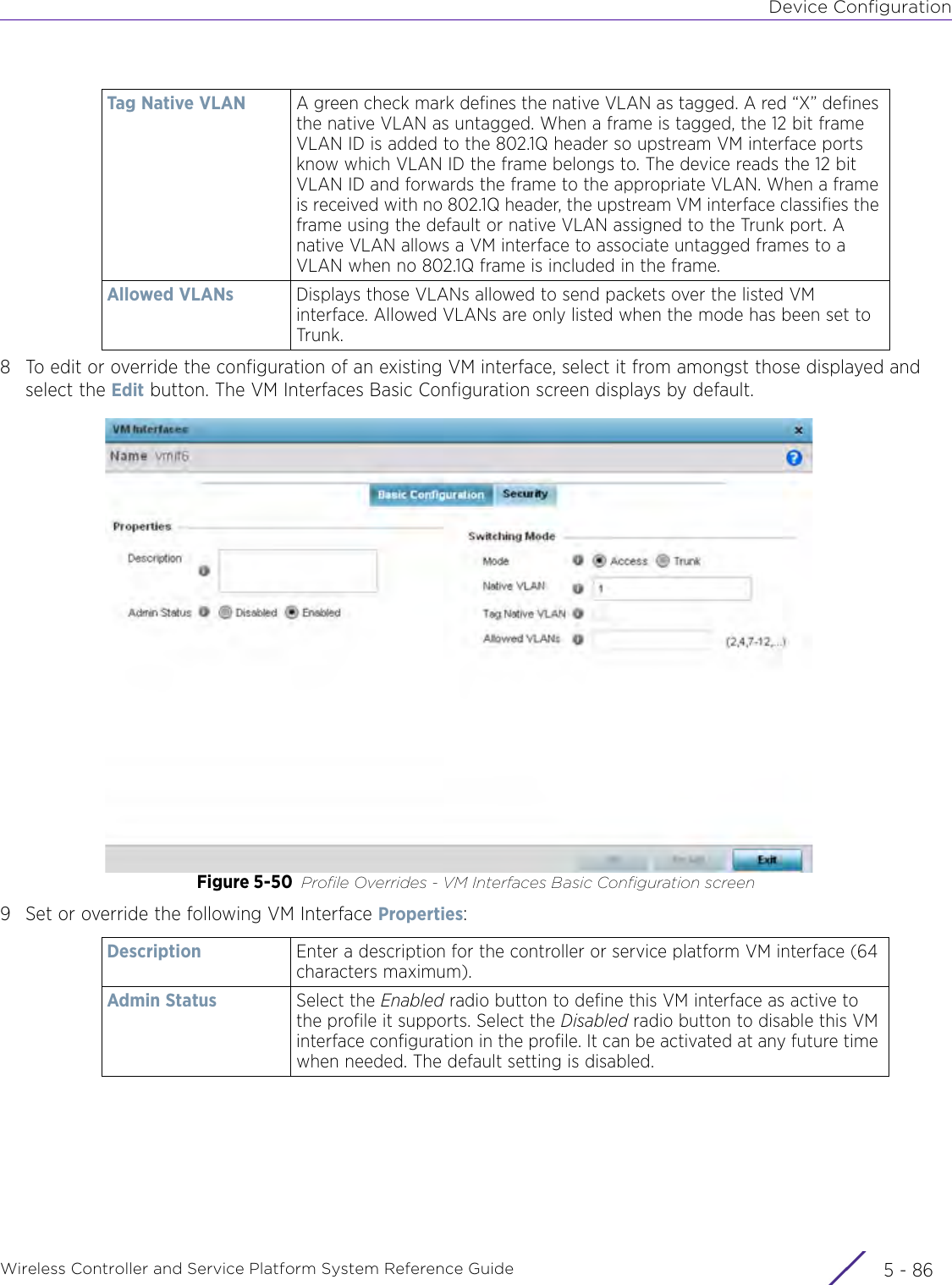
- 6. WiNG 5.9.1 System Reference Guide Part 2
- 7. WiNG 5.9.1 System Reference Guide Part 3
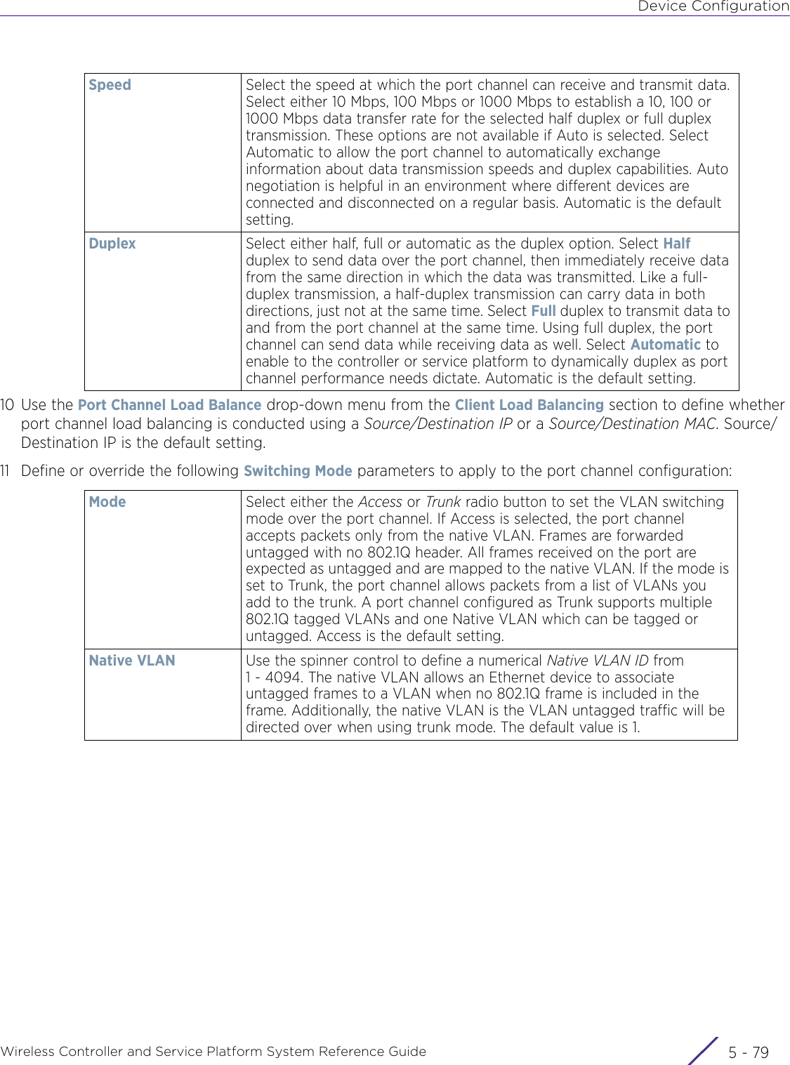
- 8. WiNG 5.9.1 System Reference Guide Part 4
- 9. WiNG 5.9.1 CLI Reference Guide Part 1
- 10. WiNG 5.9.1 CLI Reference Guide Part 2
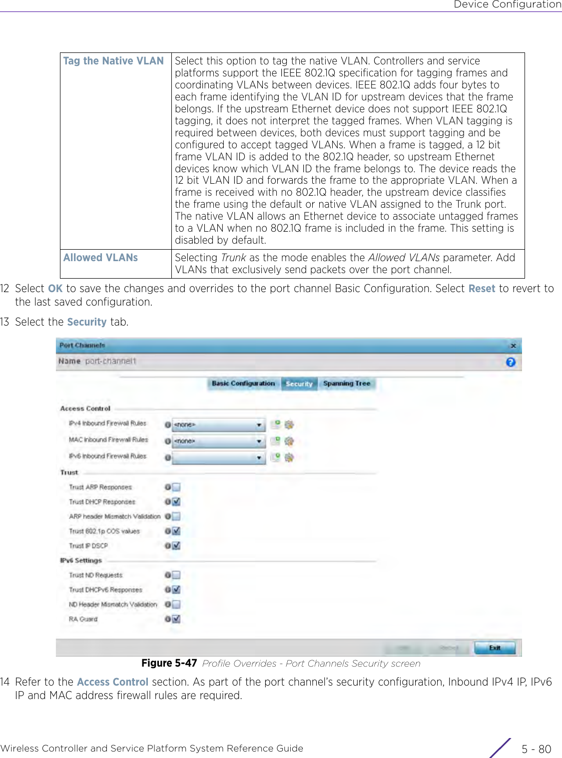
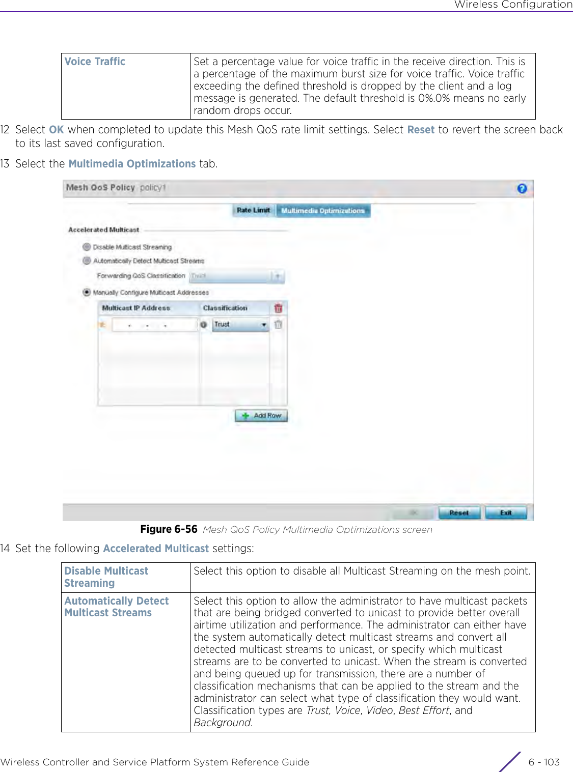
- 11. Extreme Wireless V10.41.06 User Guide Part 1
- 12. AP3917 User Manual
- 13. AP7662 User Manual
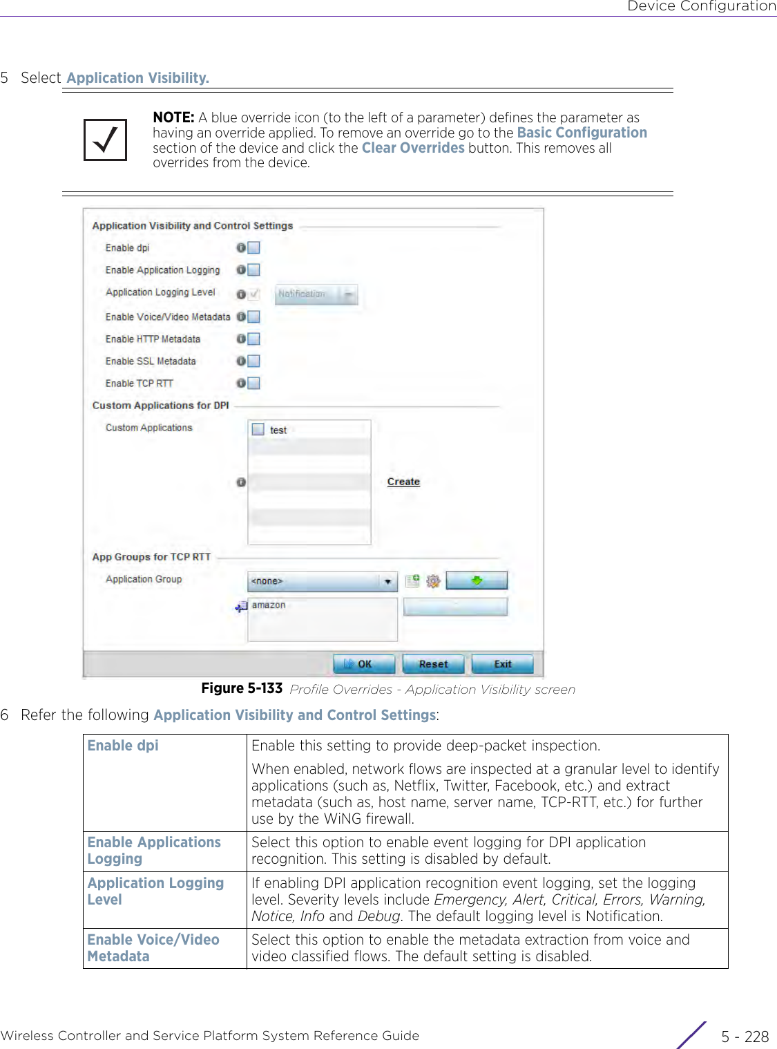
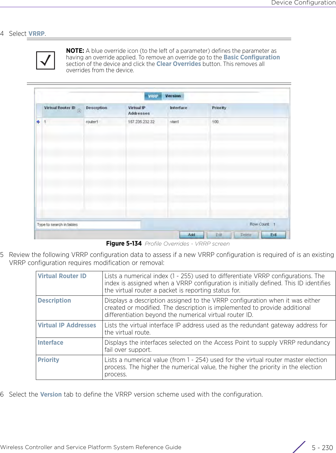
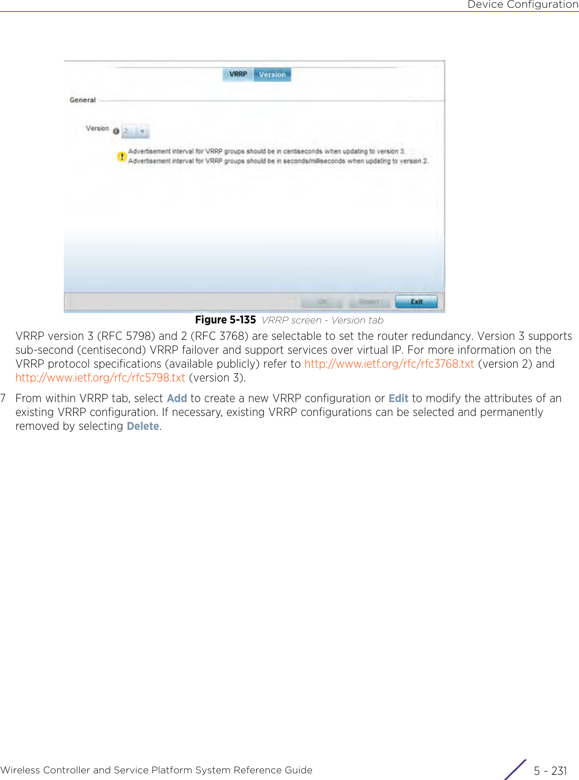
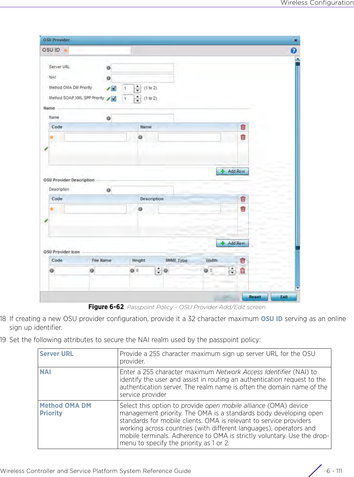
WiNG 5.9.1 System Reference Guide Part 1
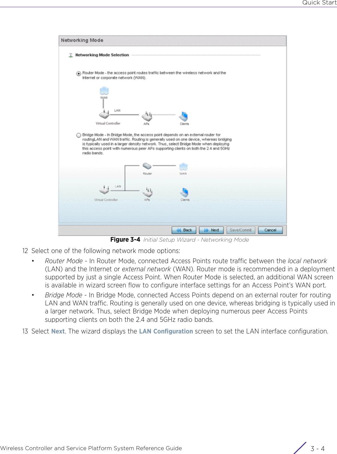
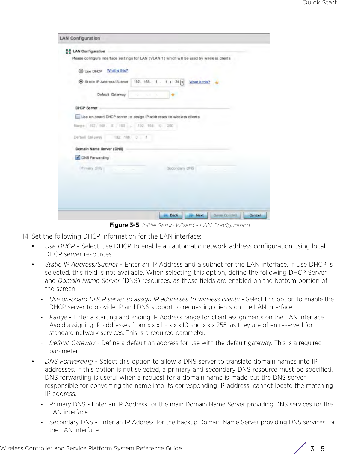
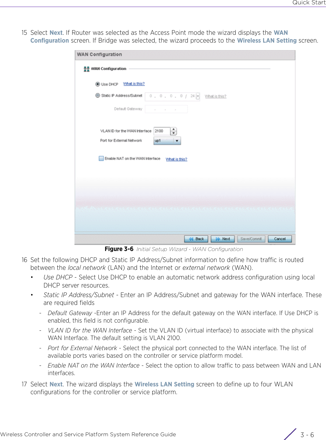
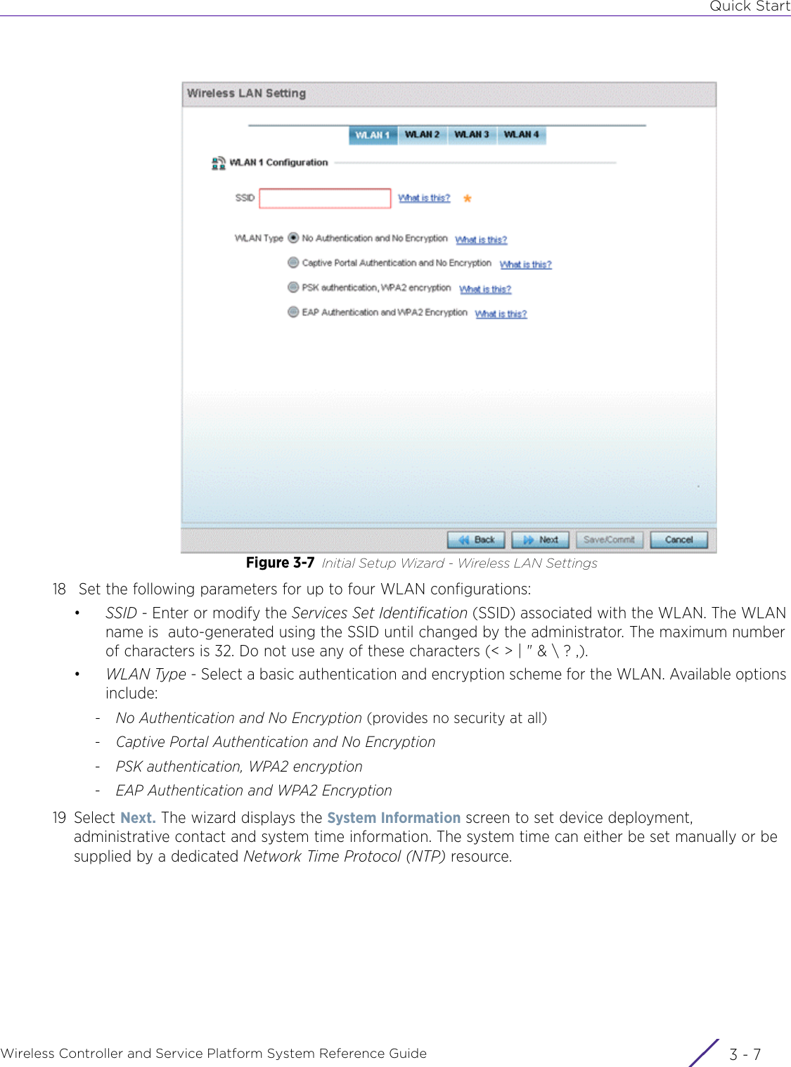
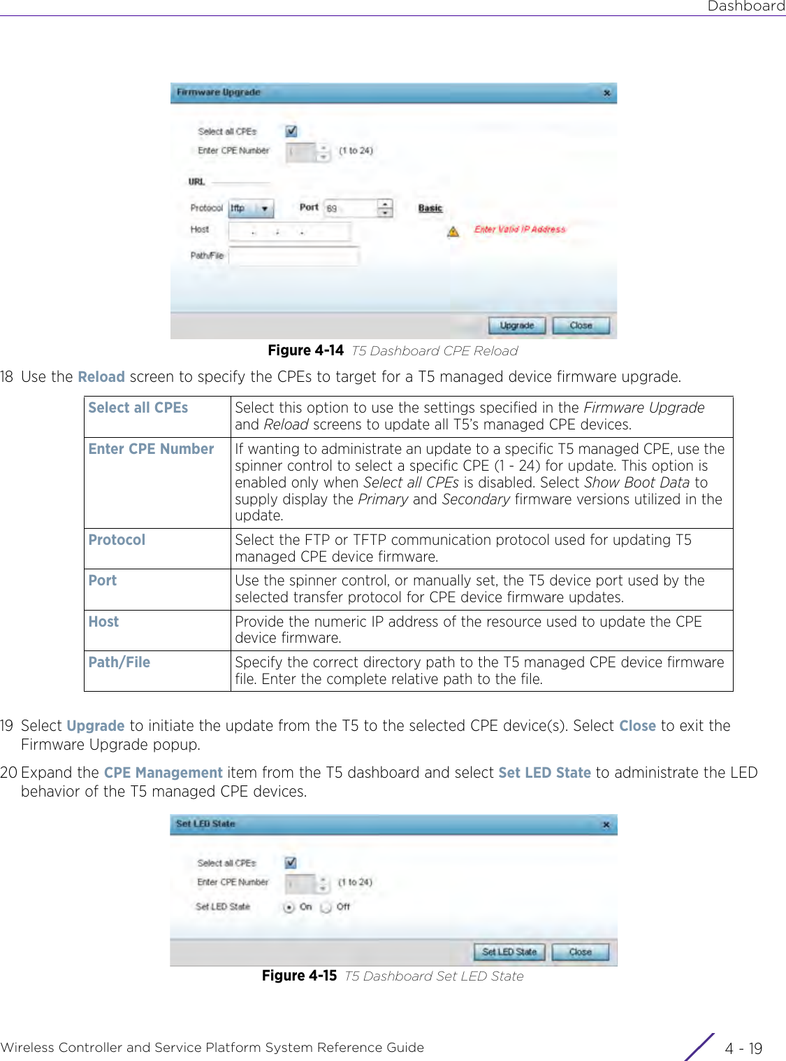
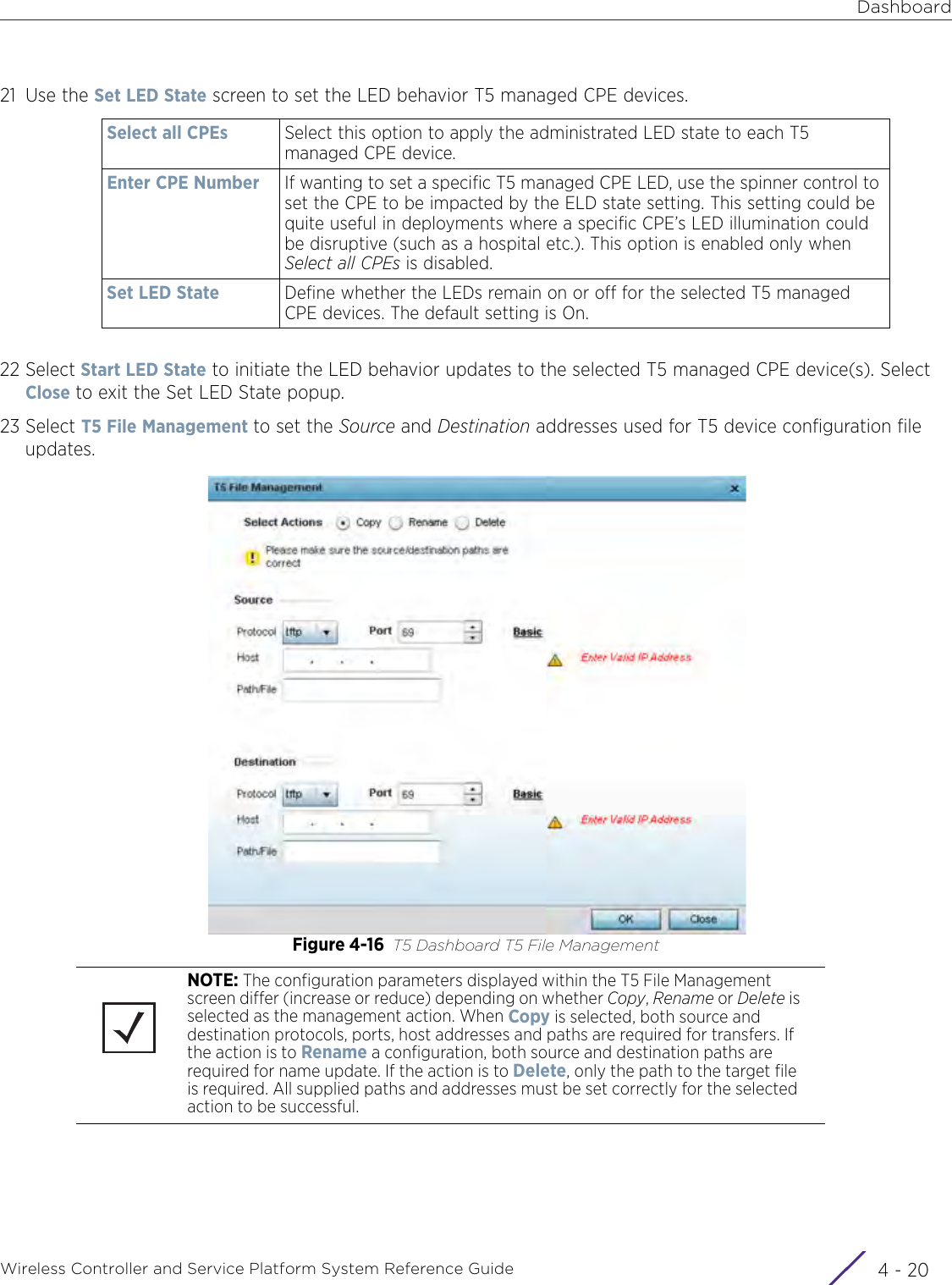
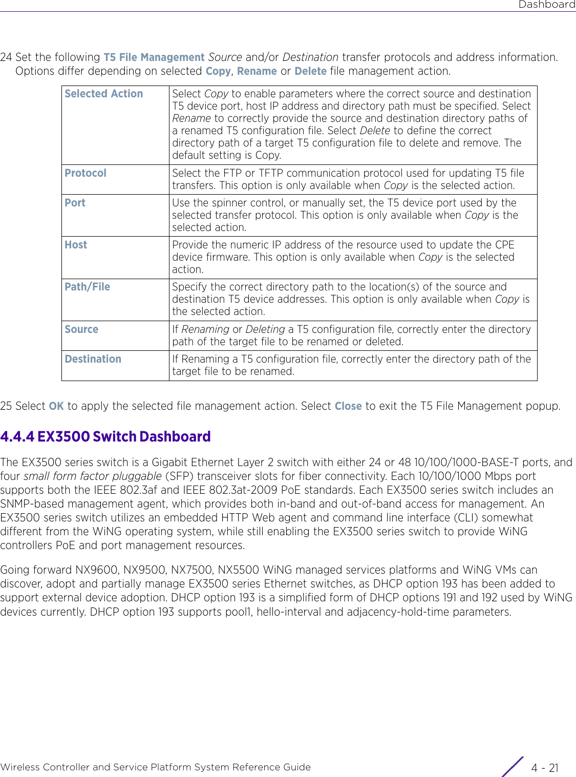
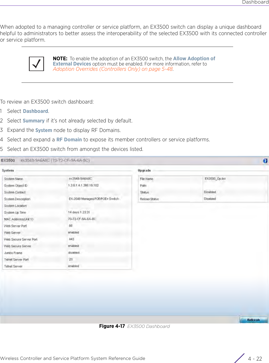
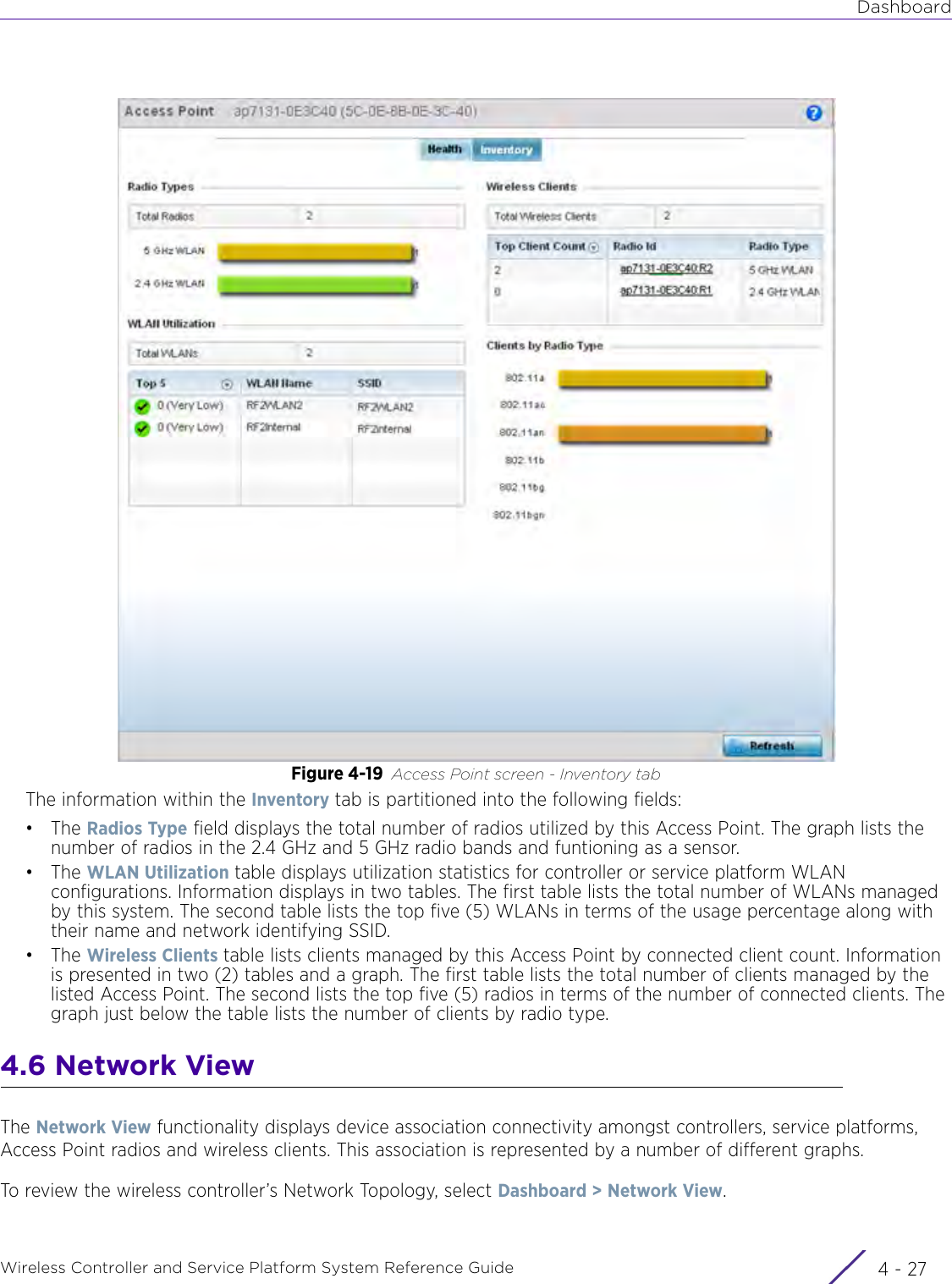
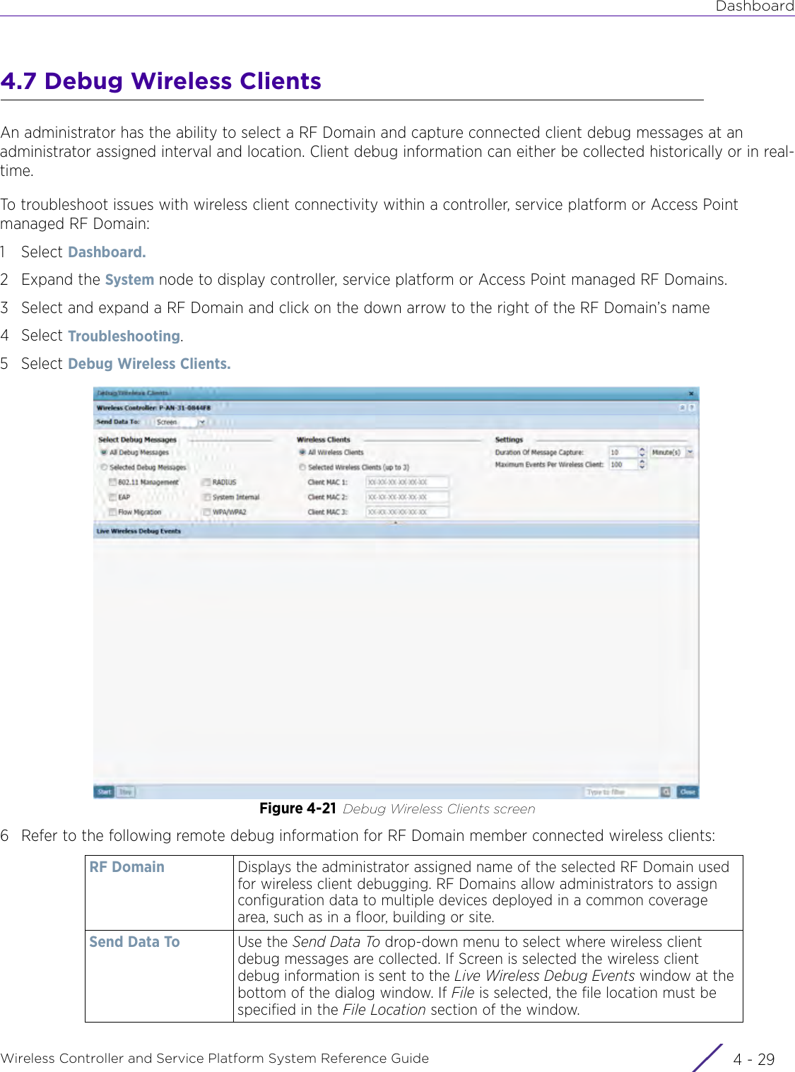
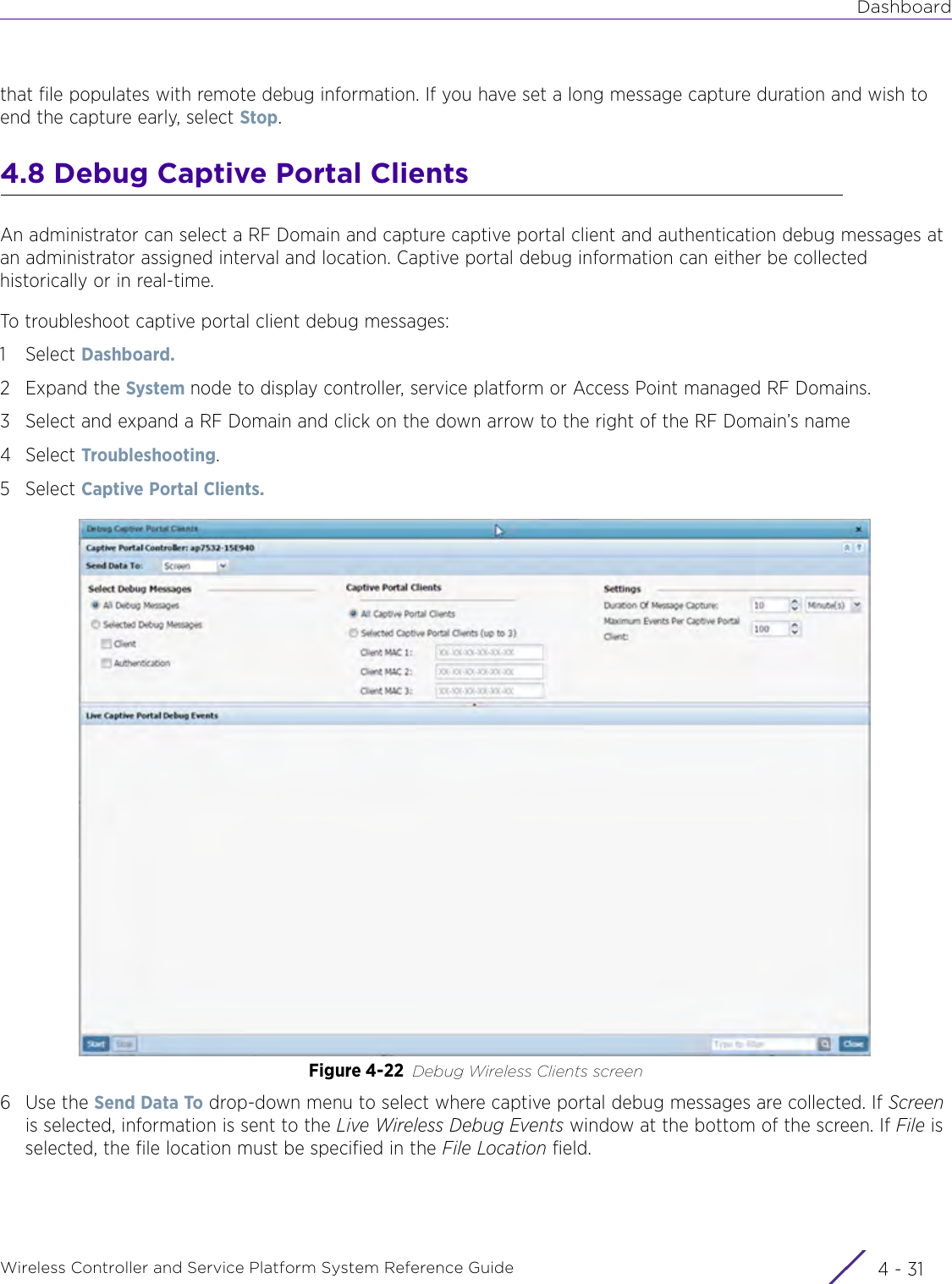
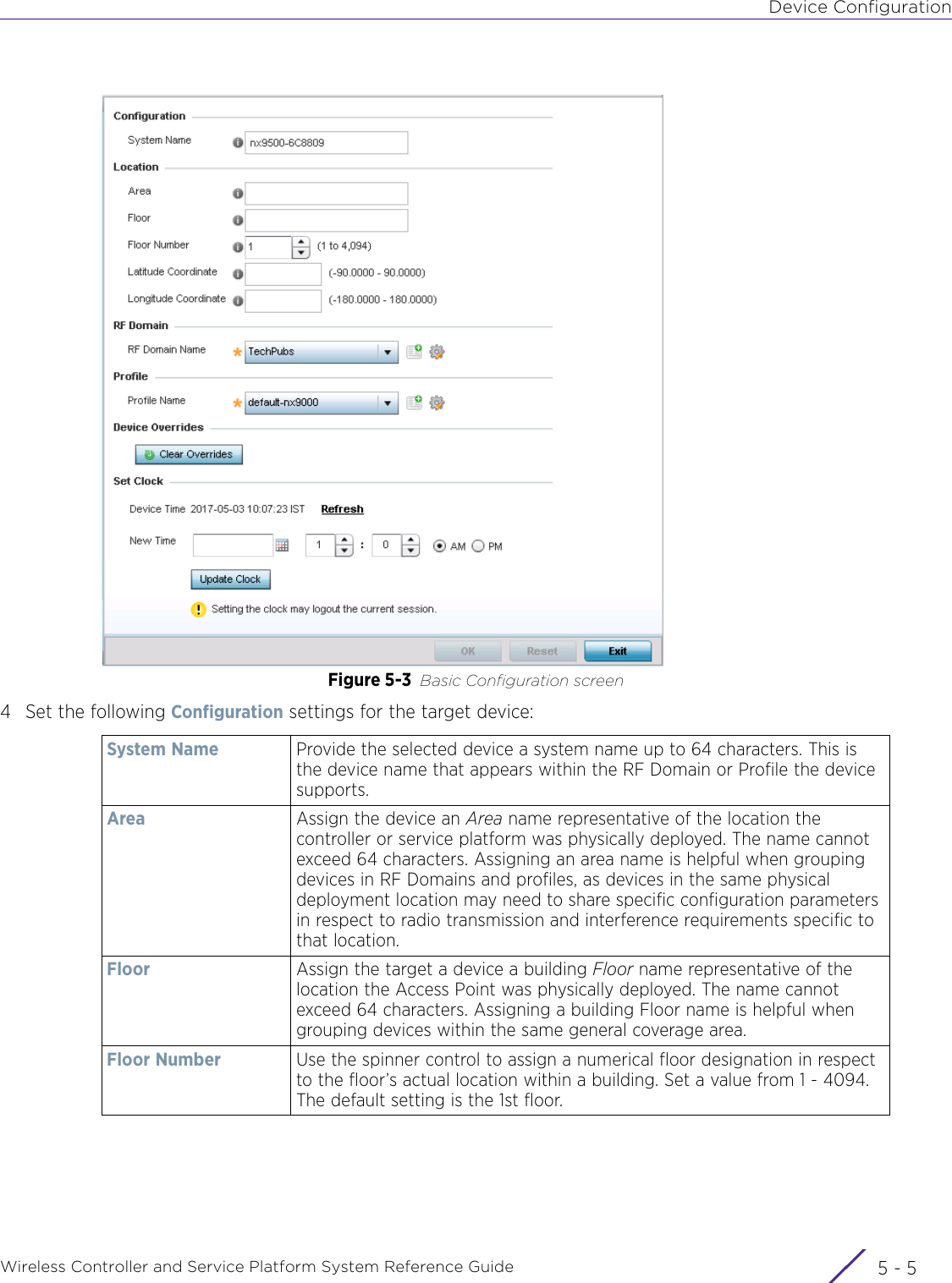
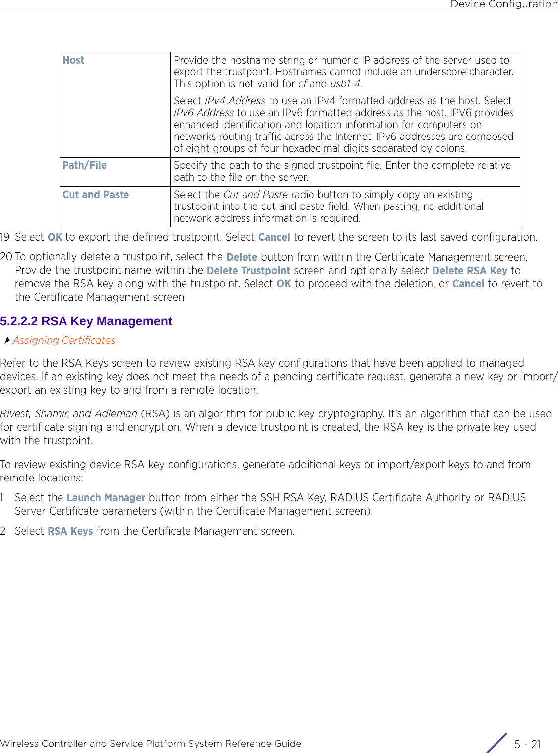
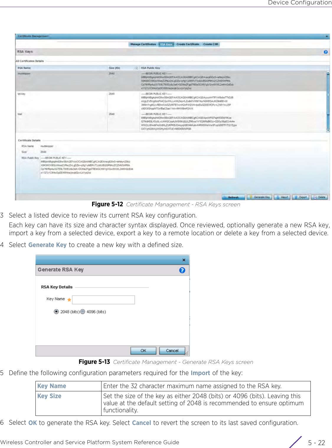
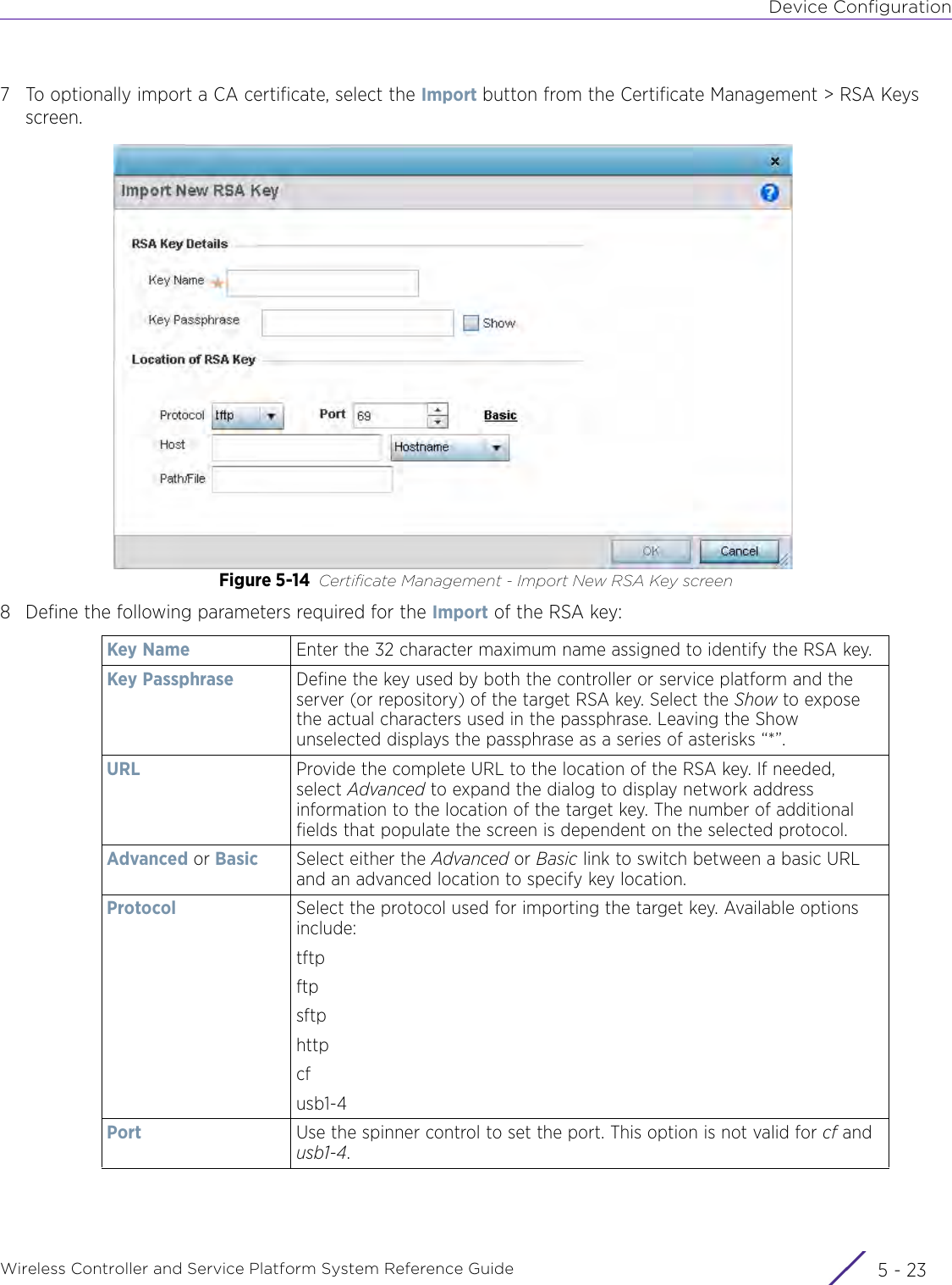
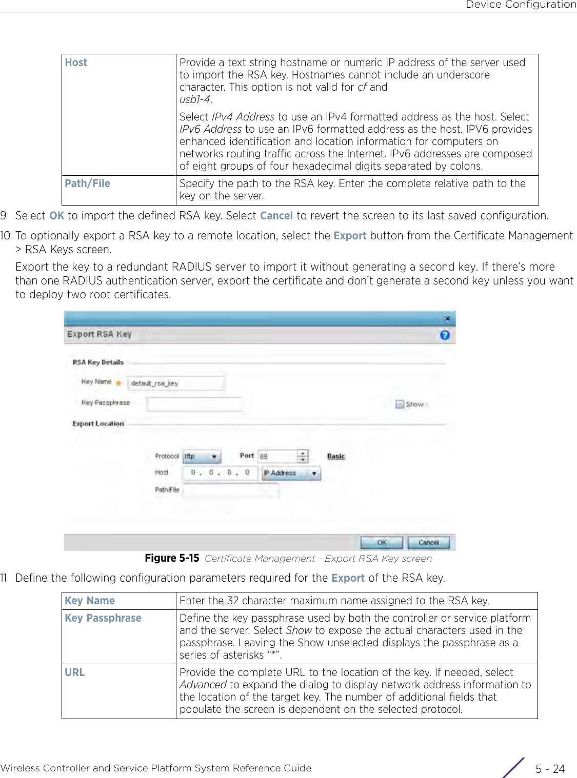
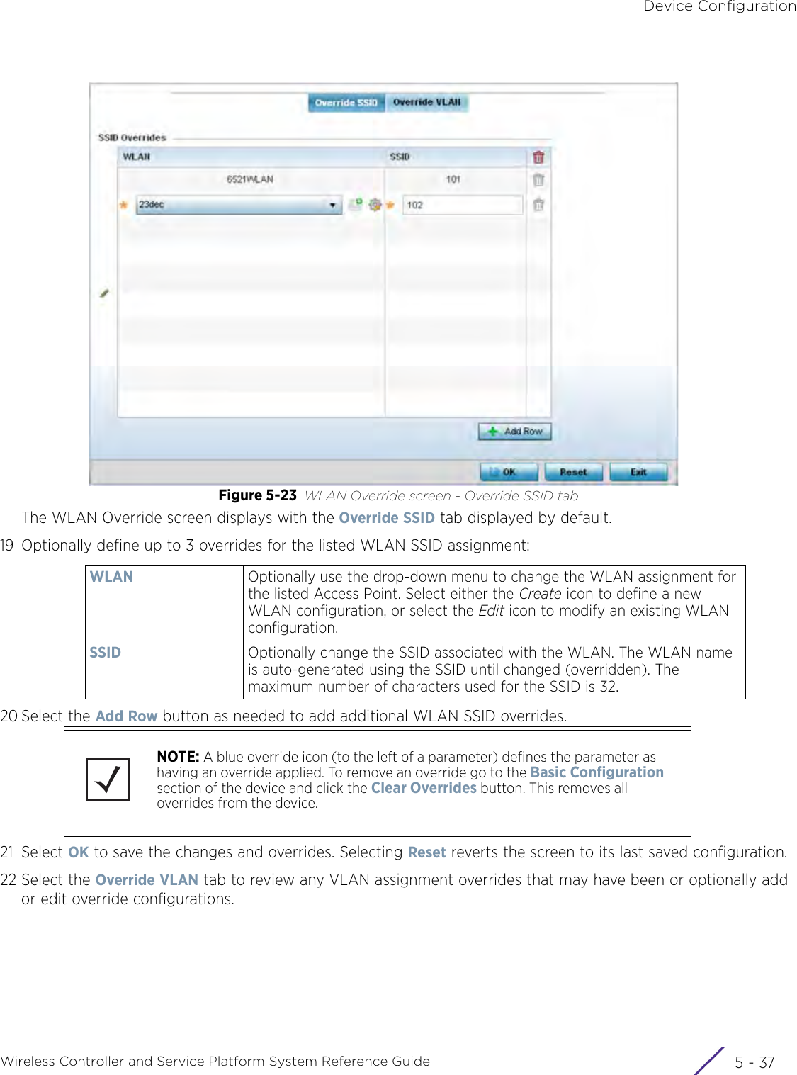
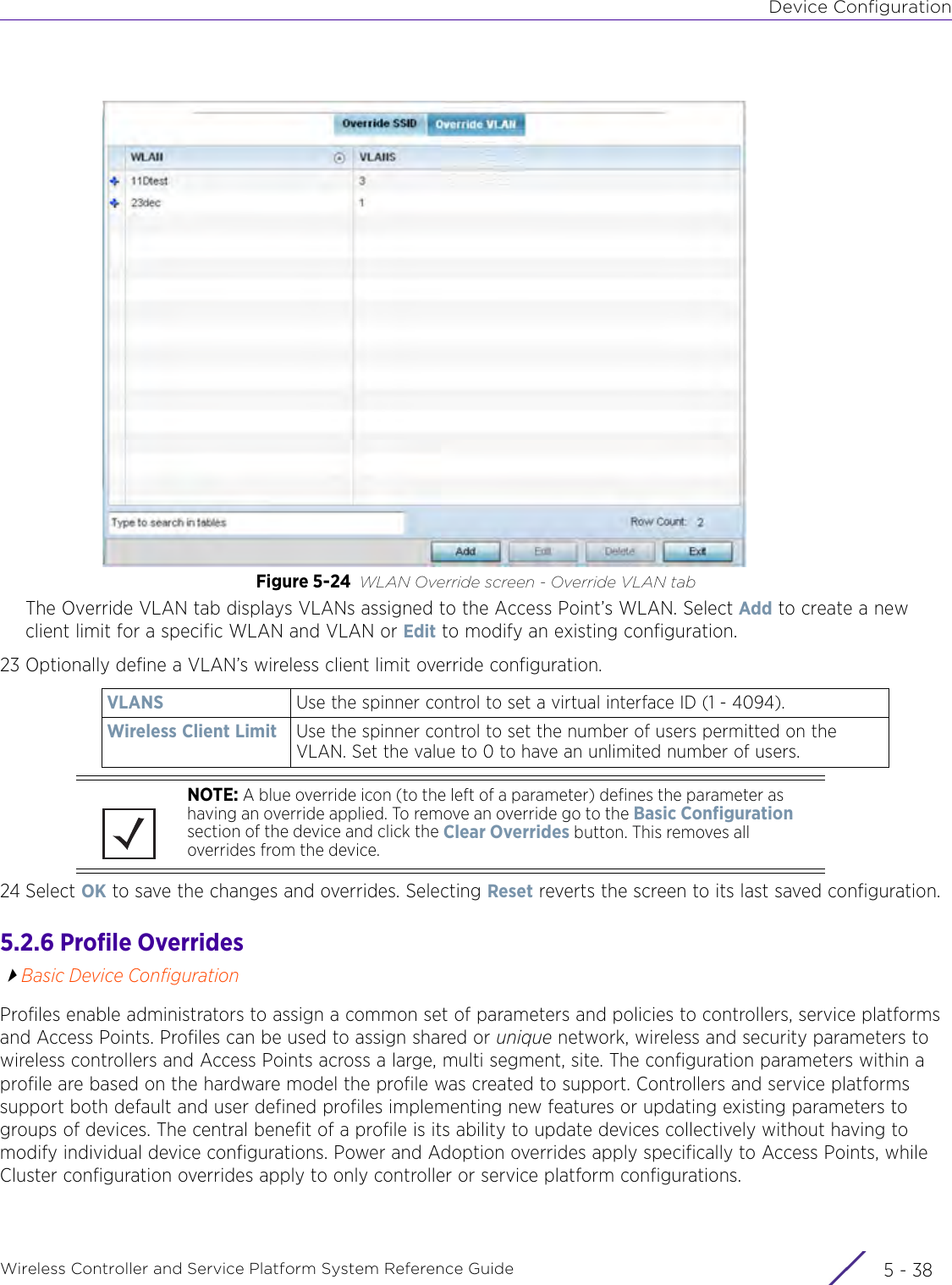
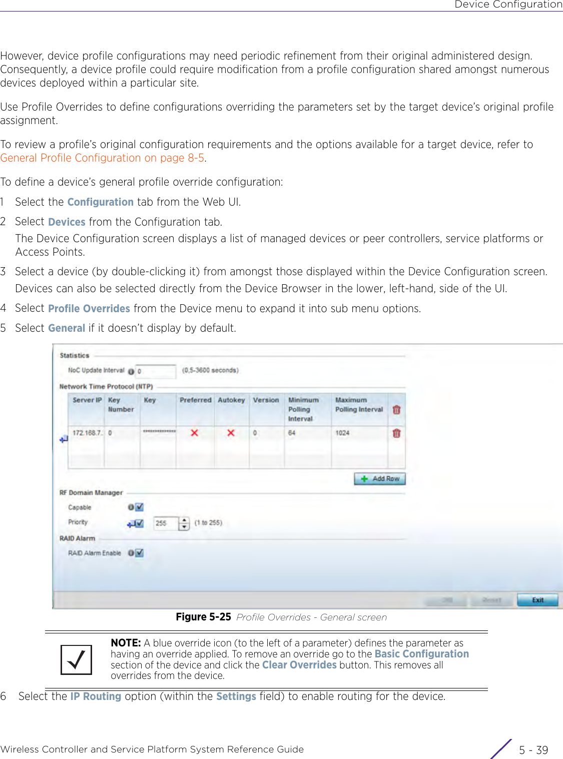
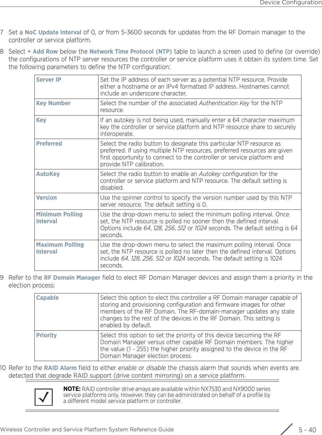
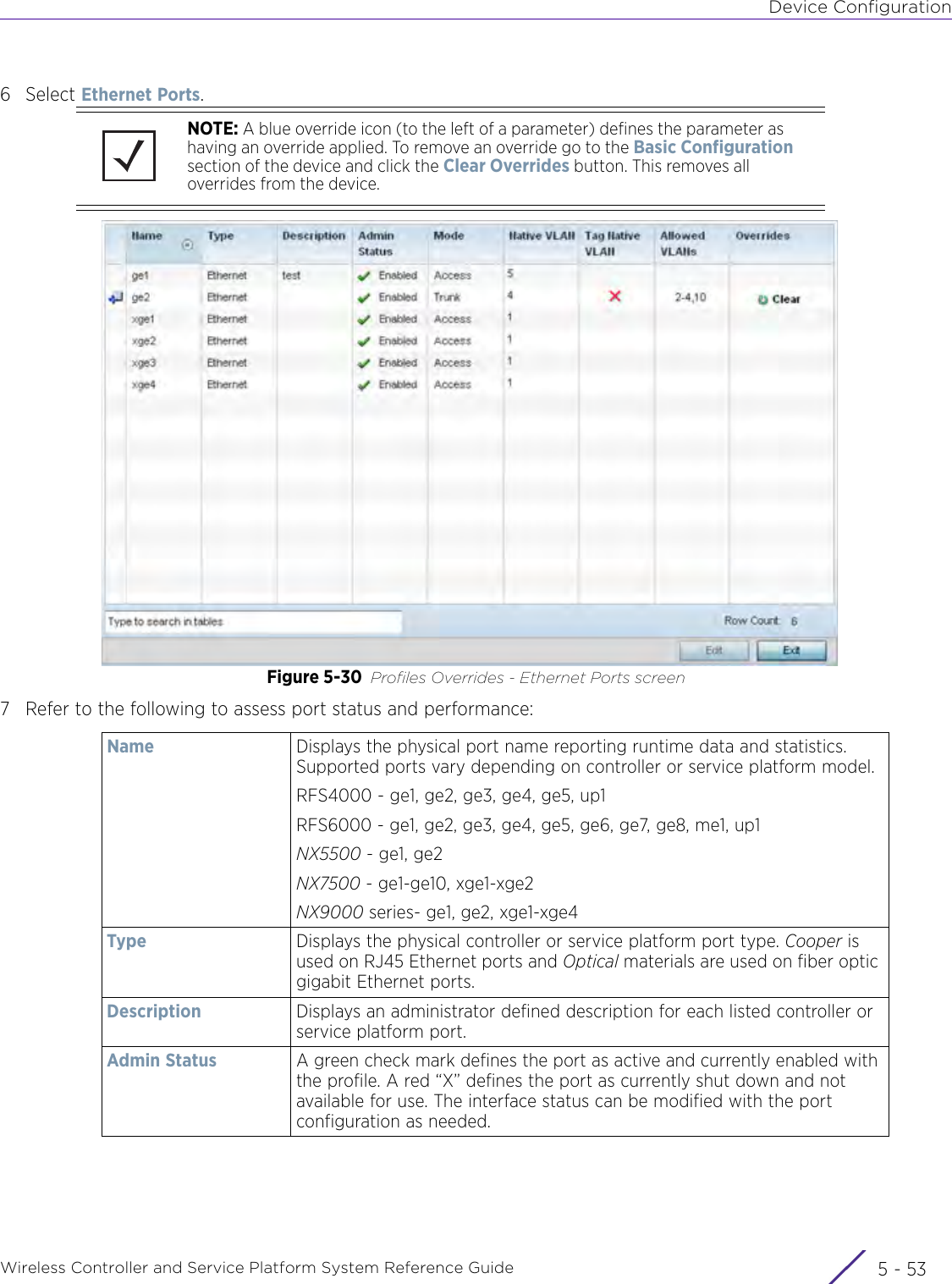
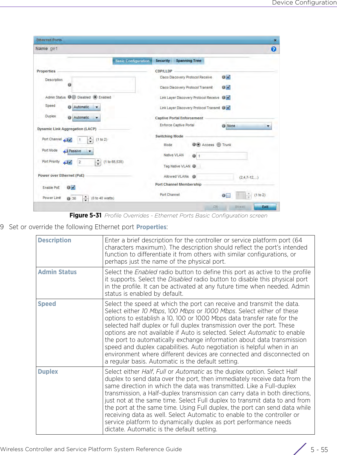
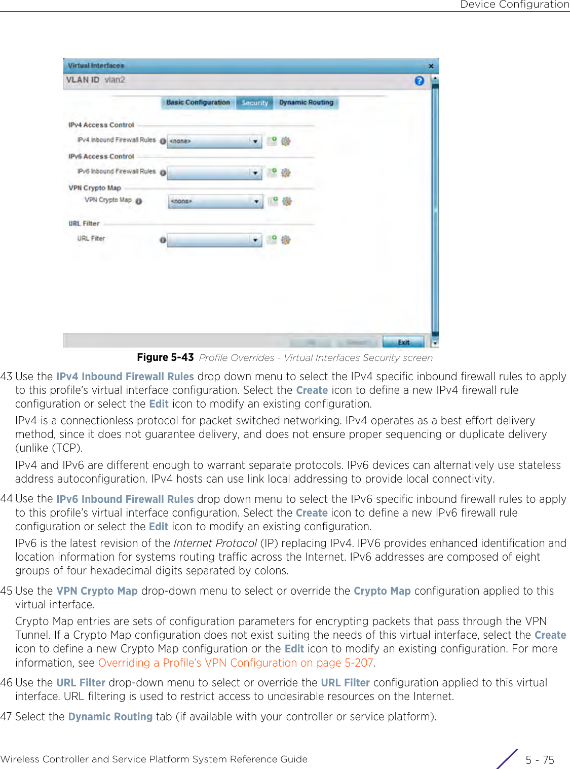
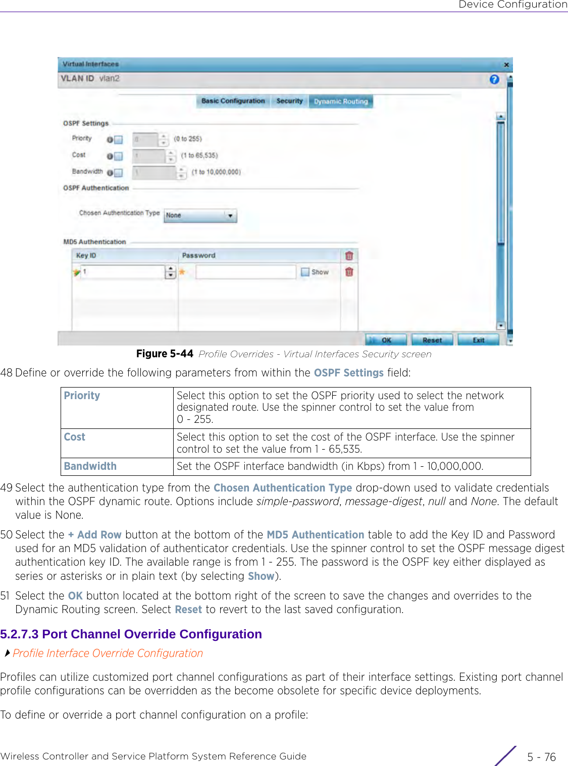
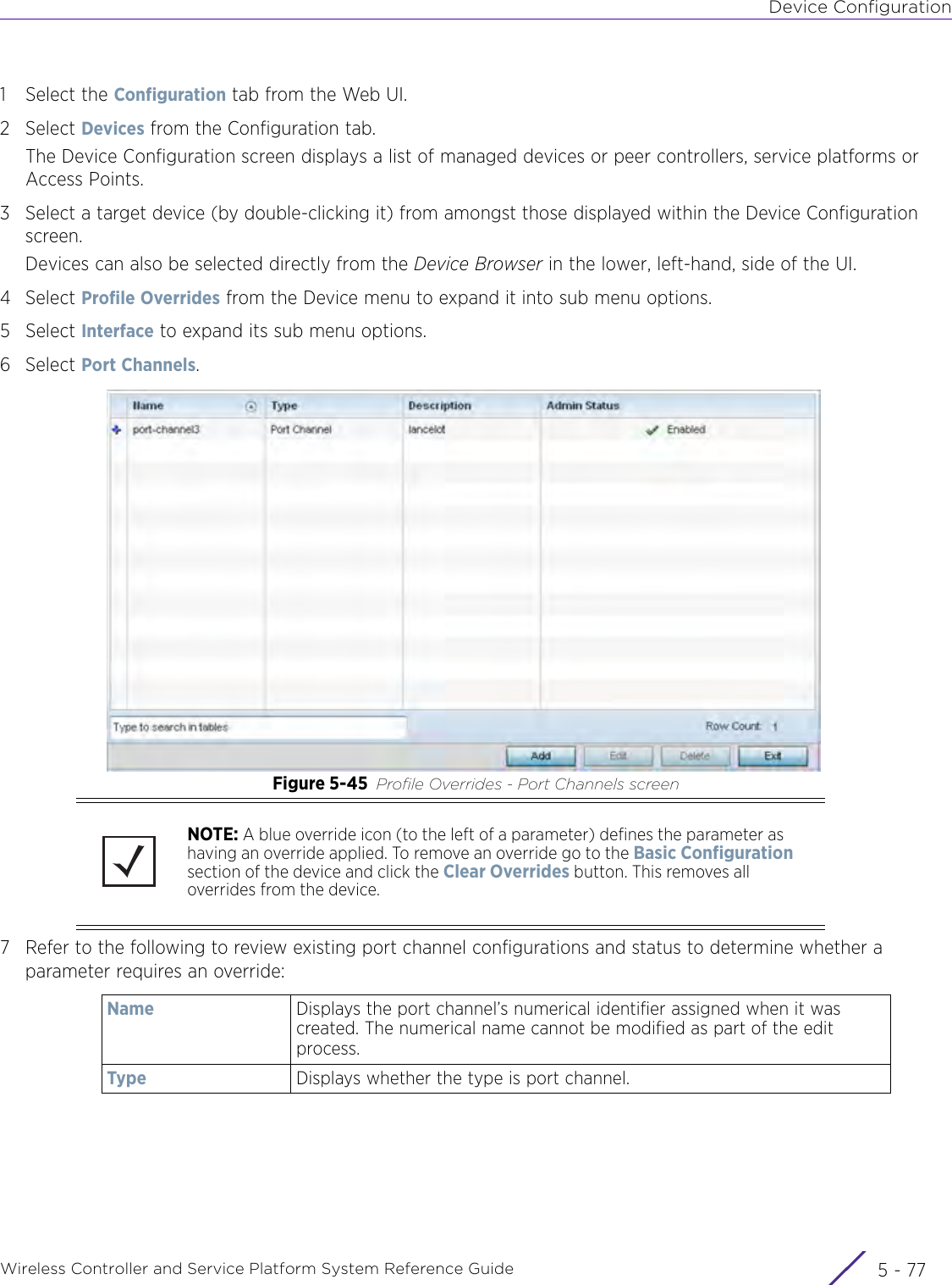
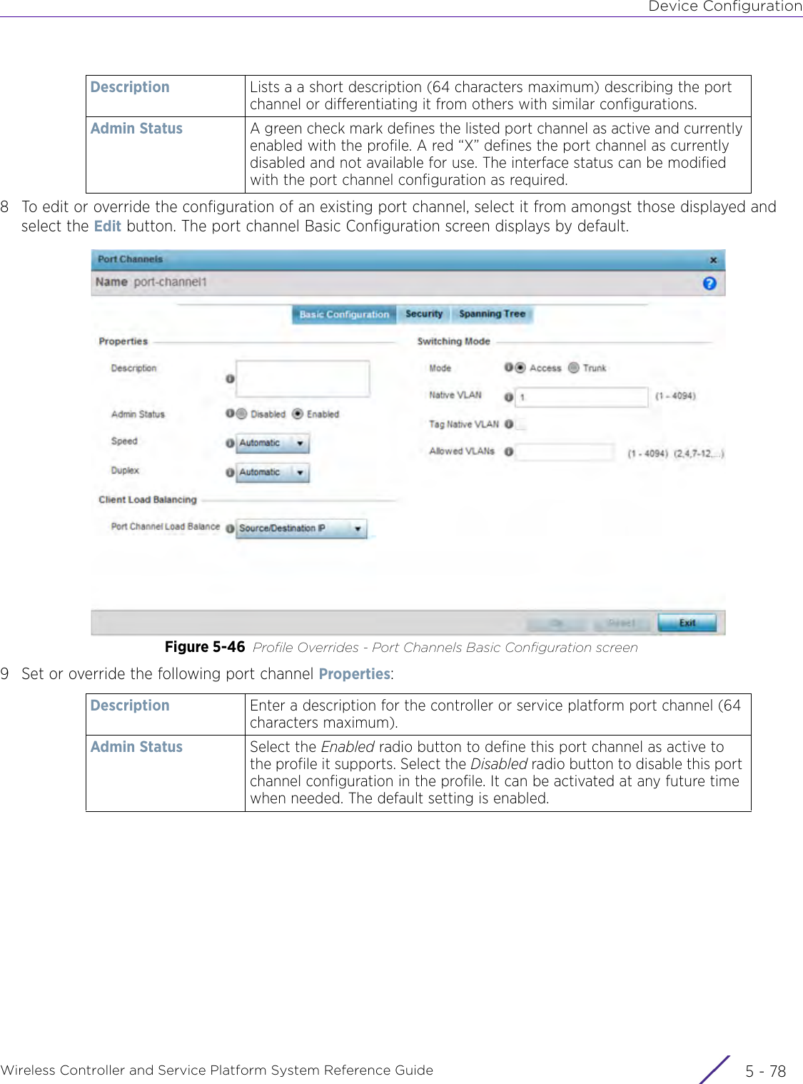
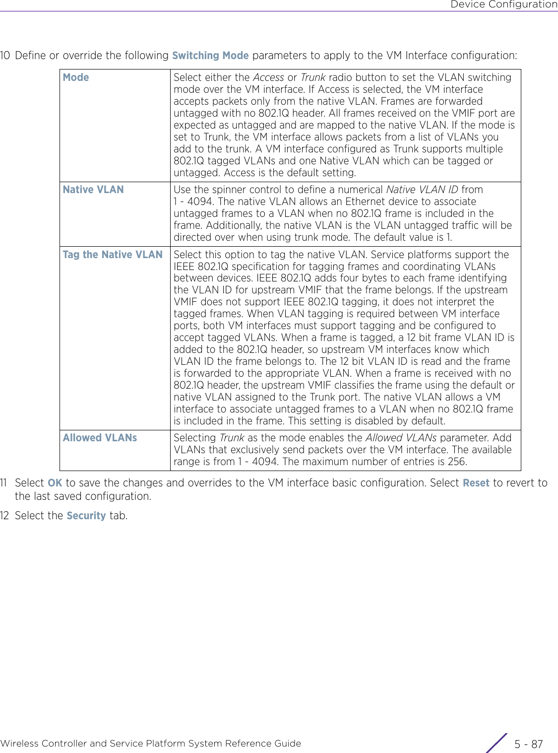
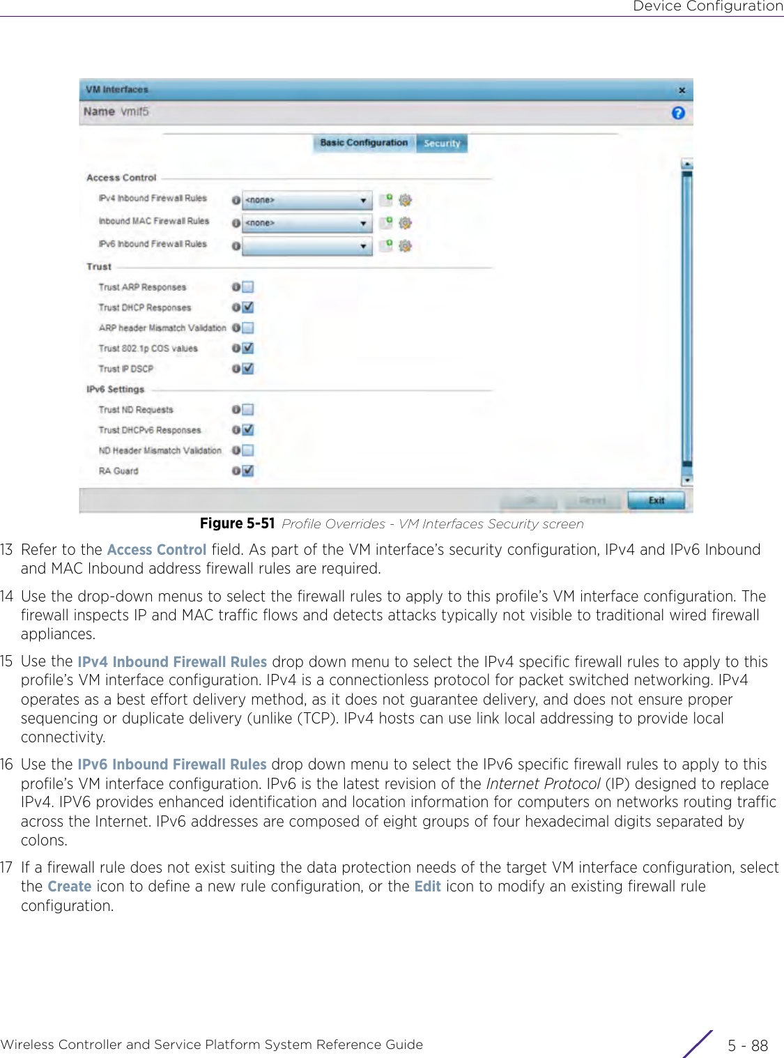
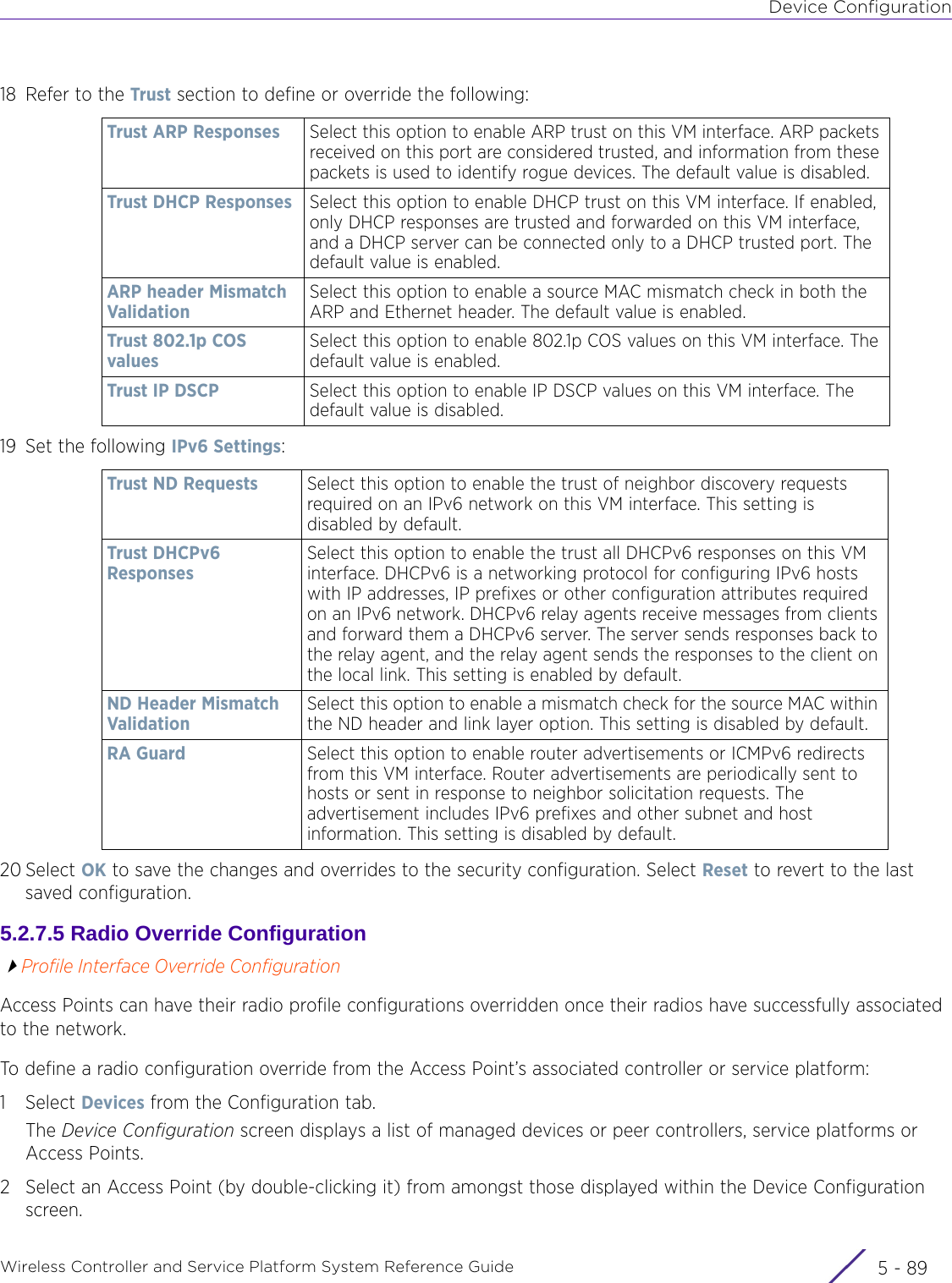
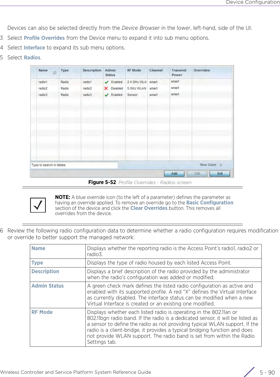
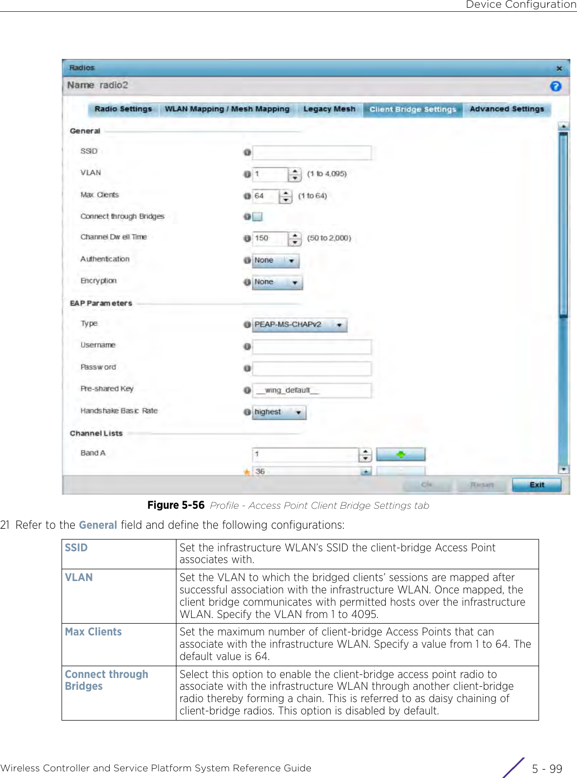
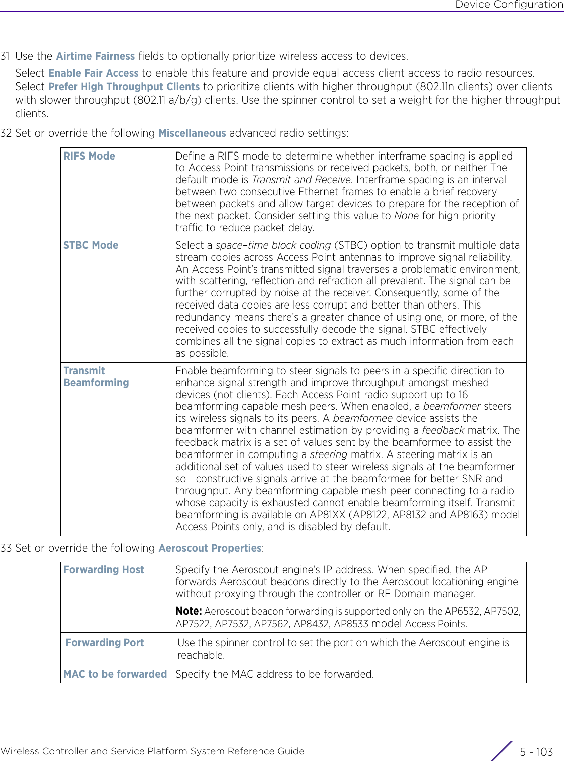
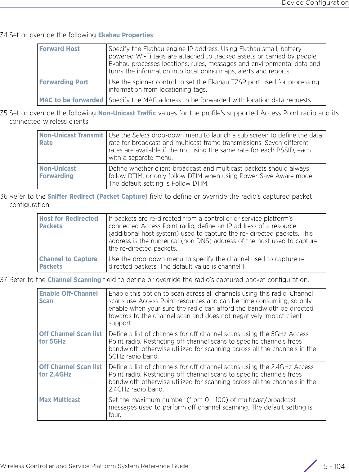
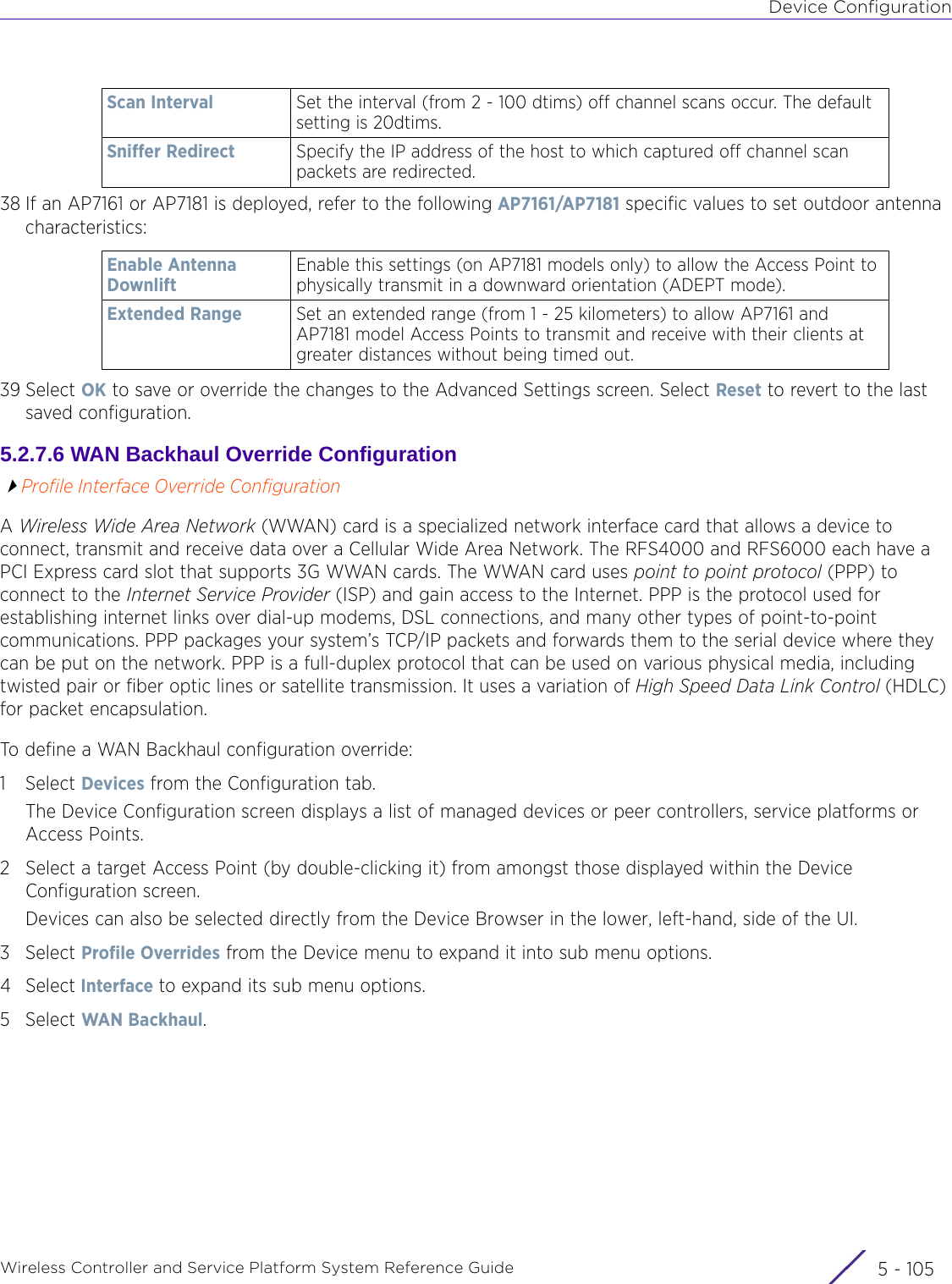
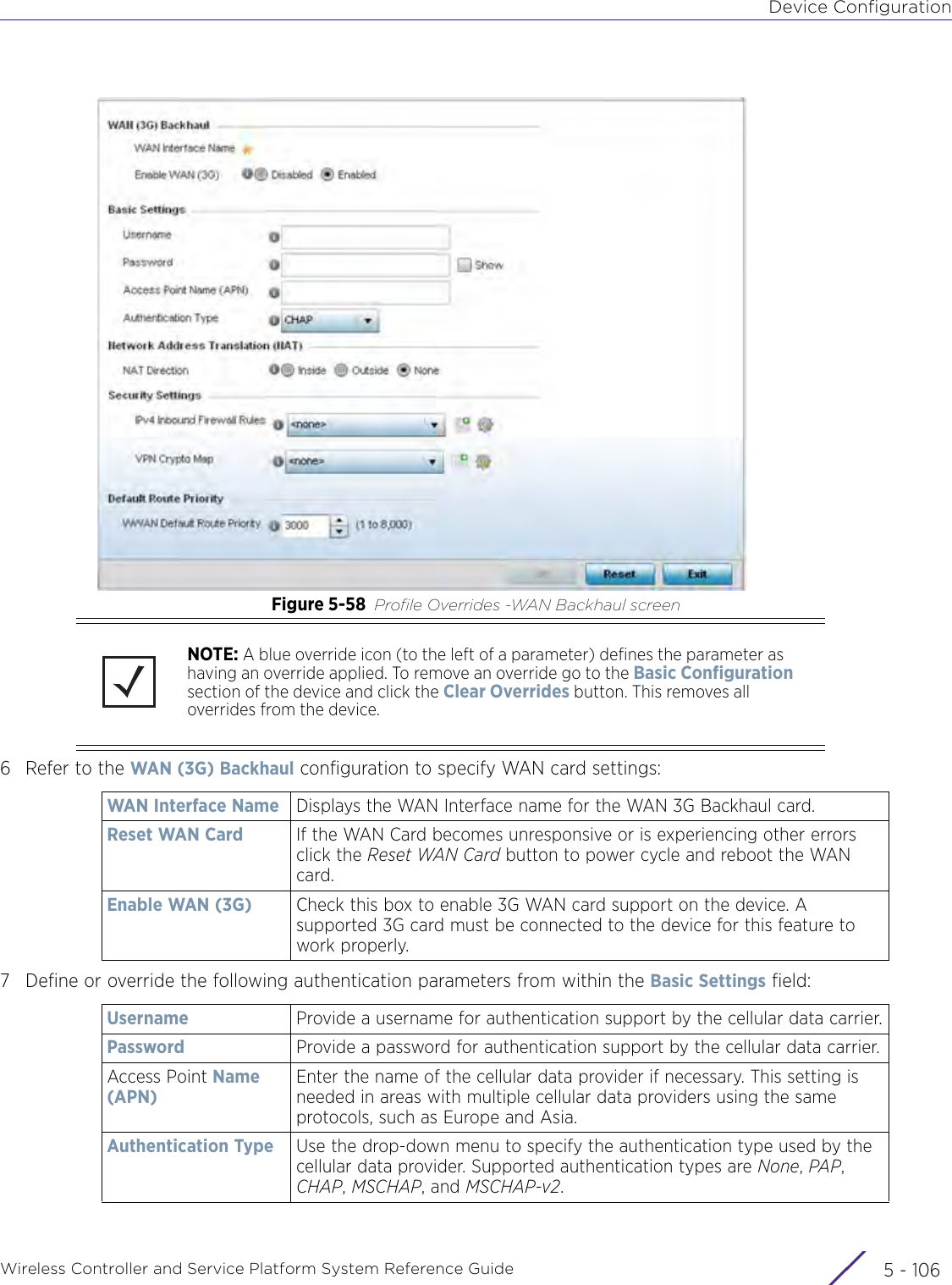
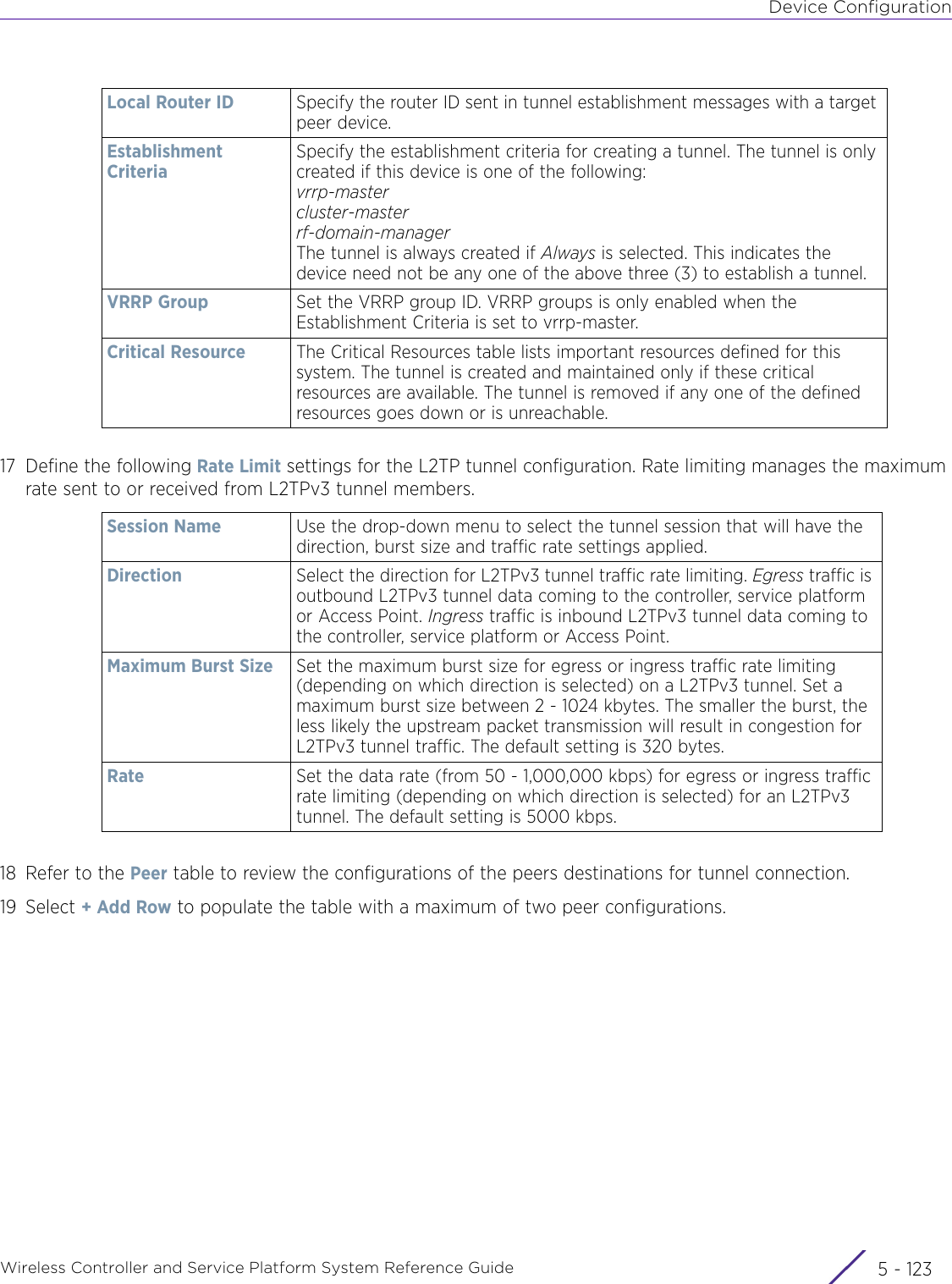
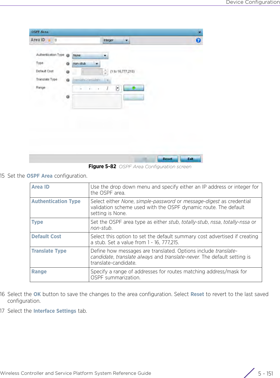
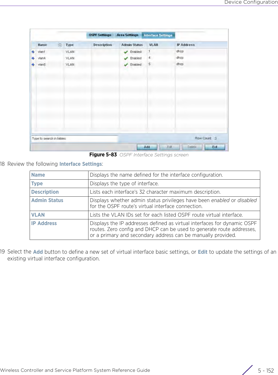
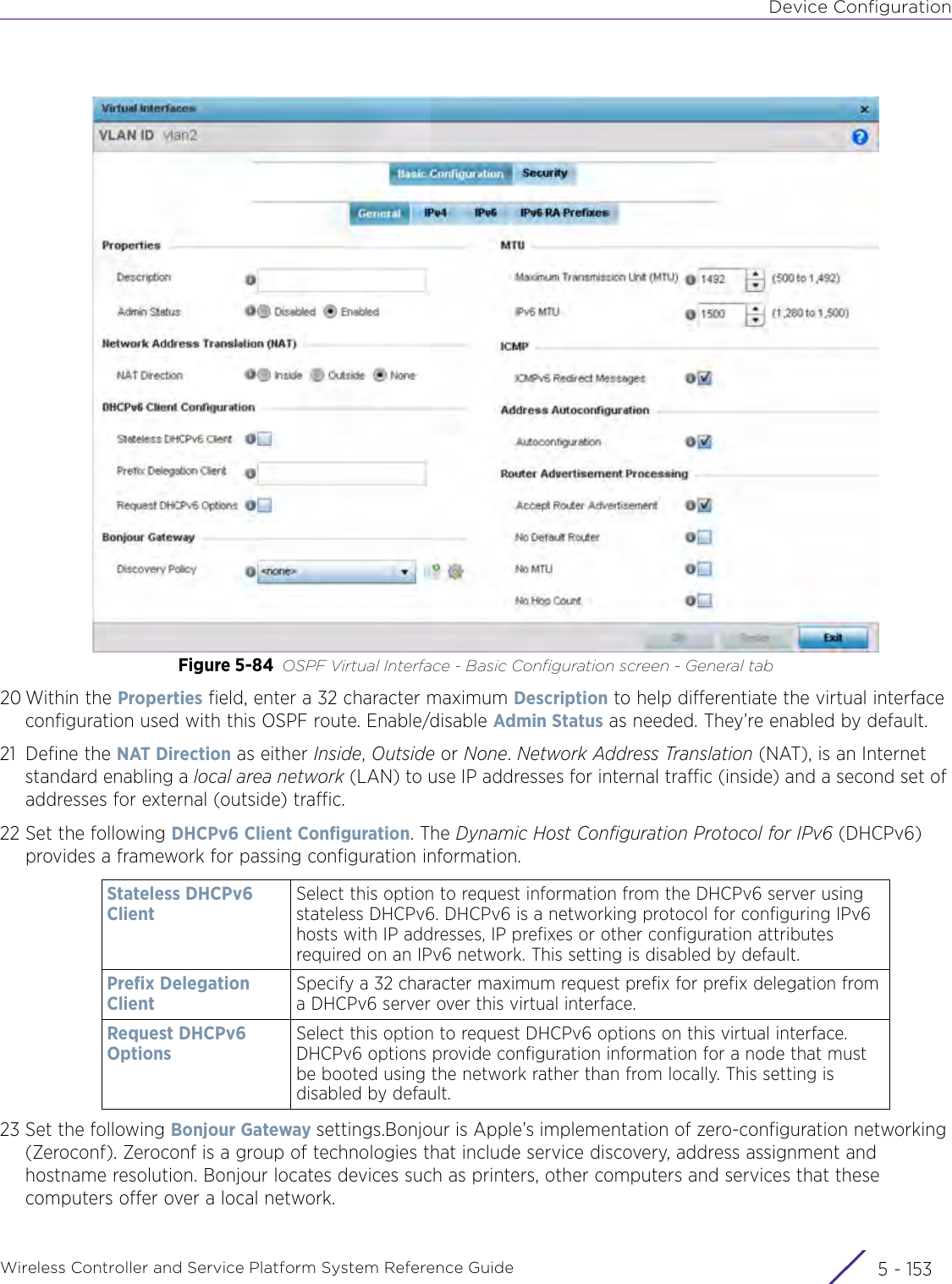
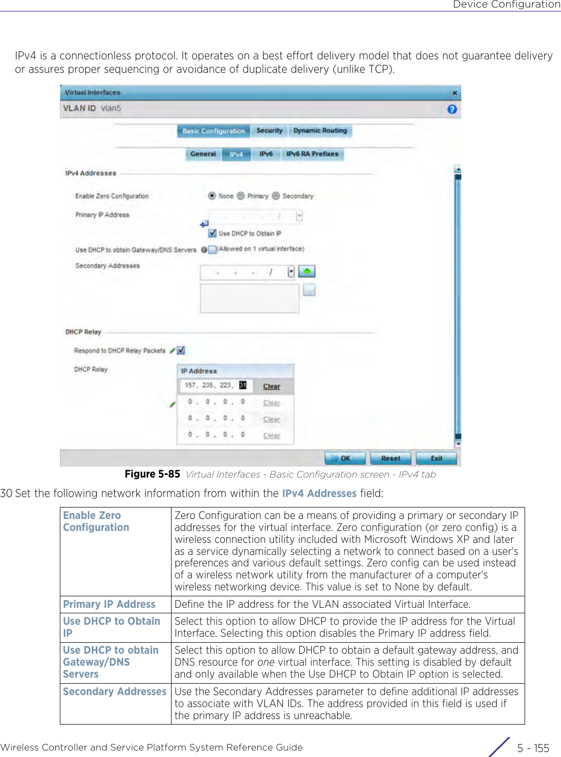
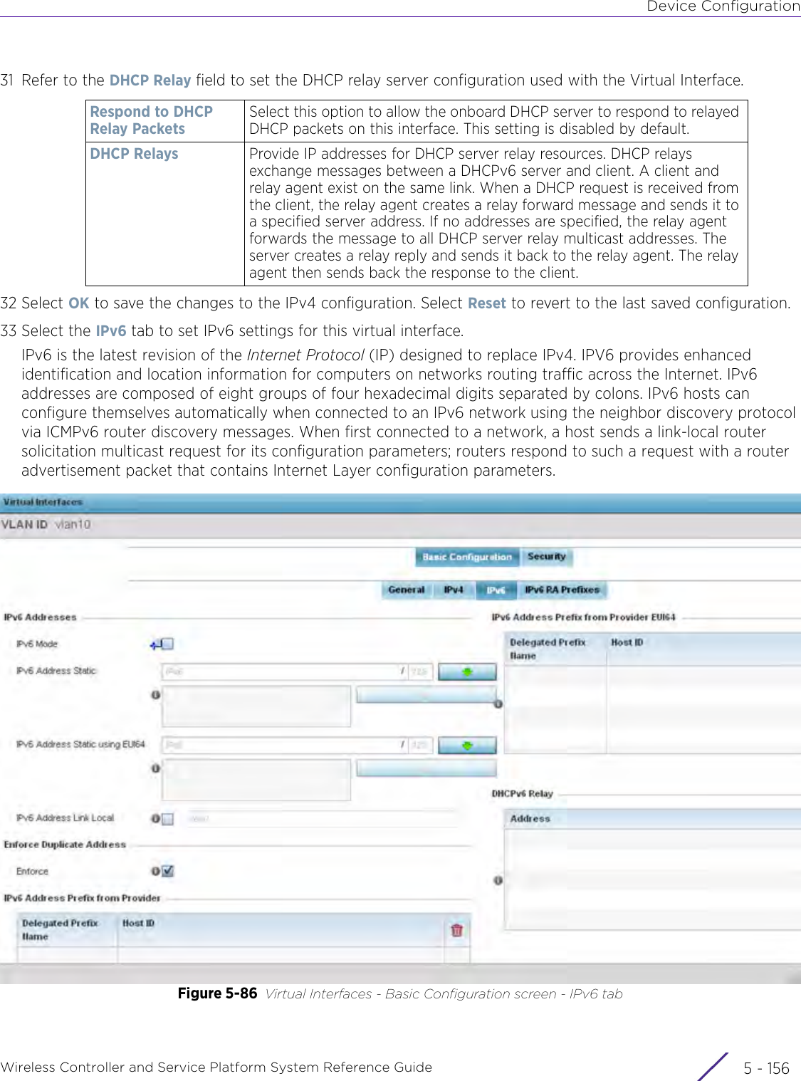
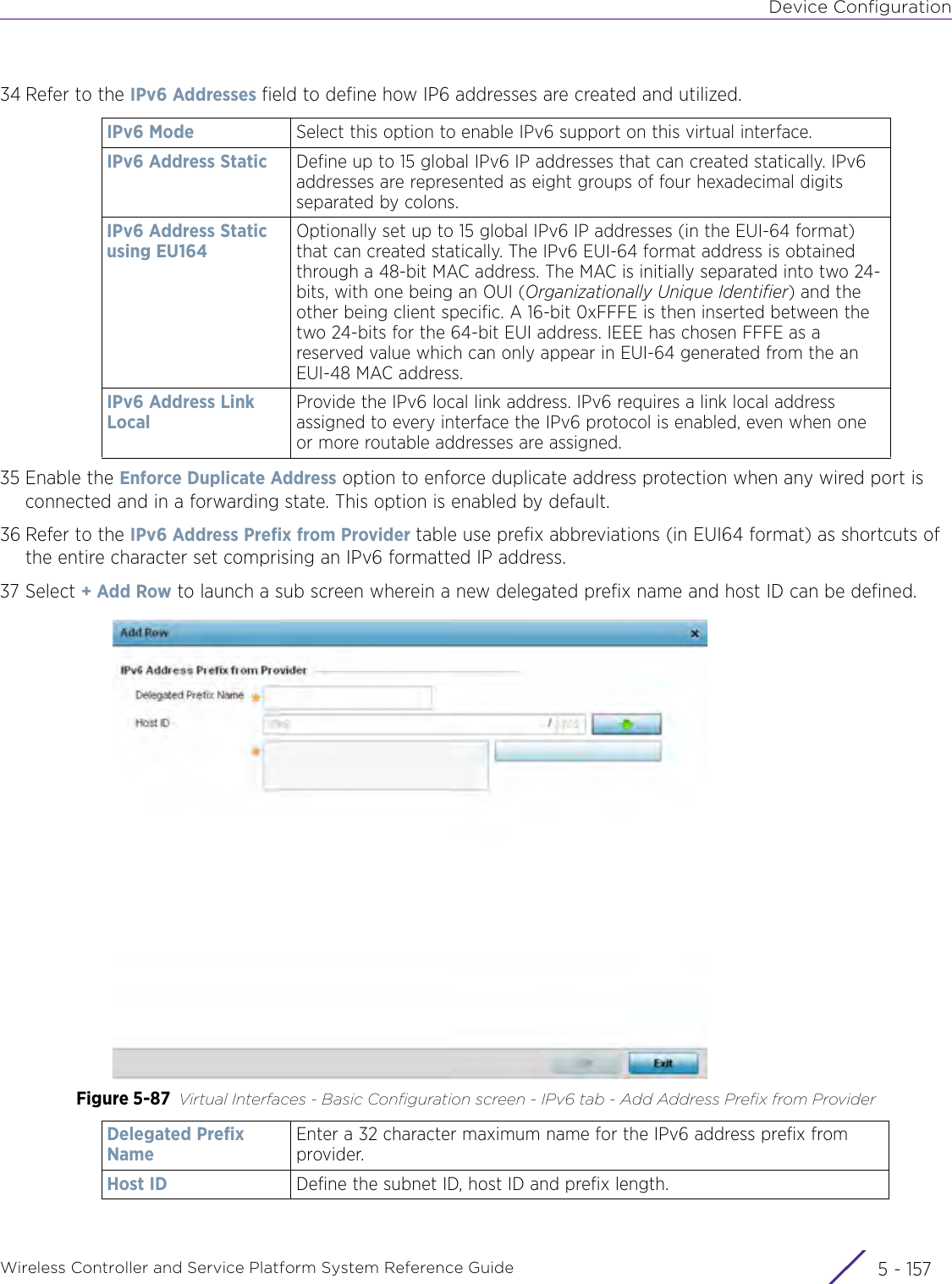
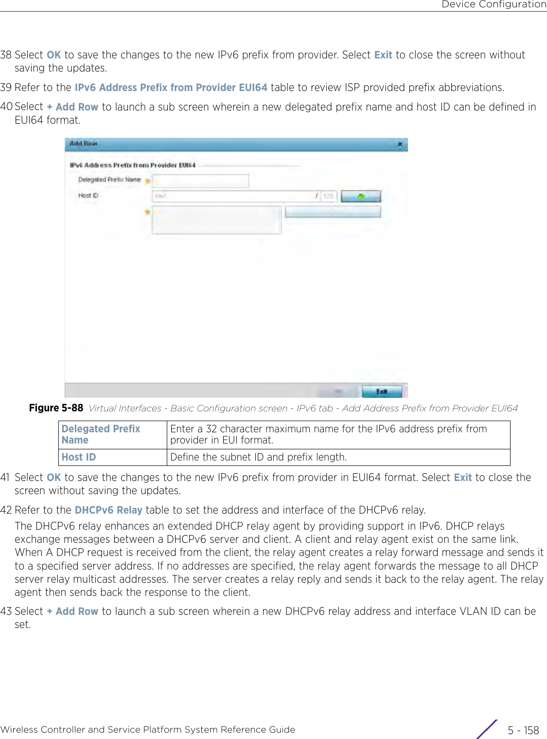
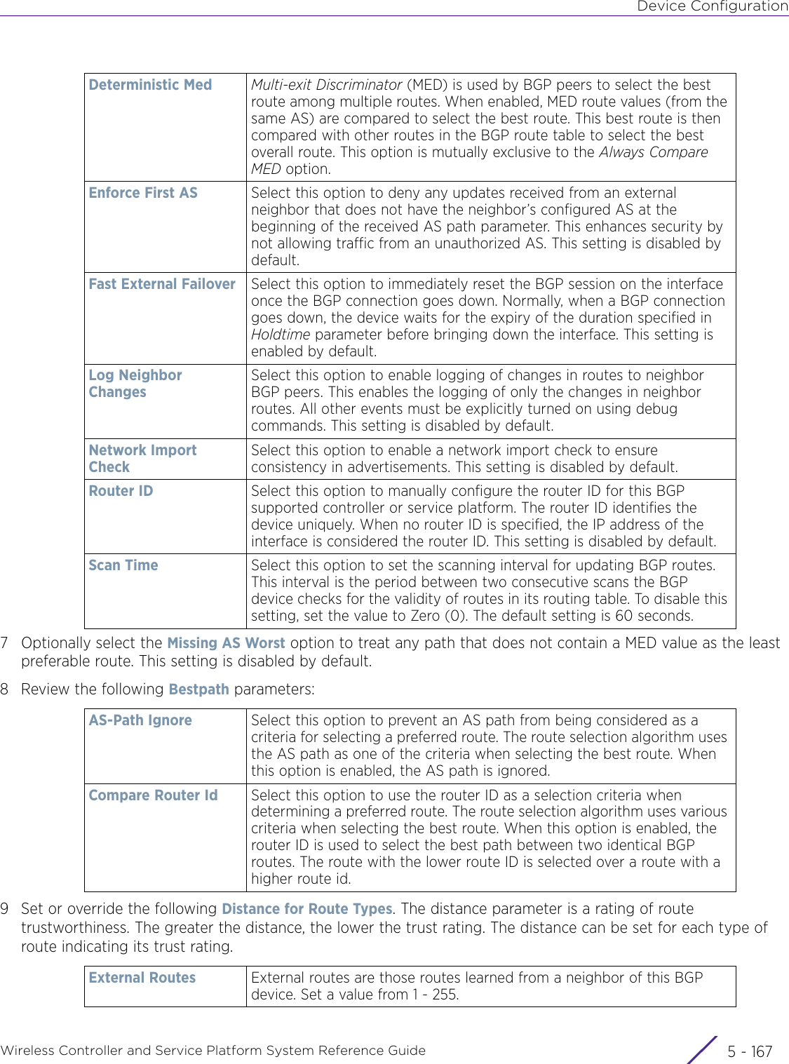
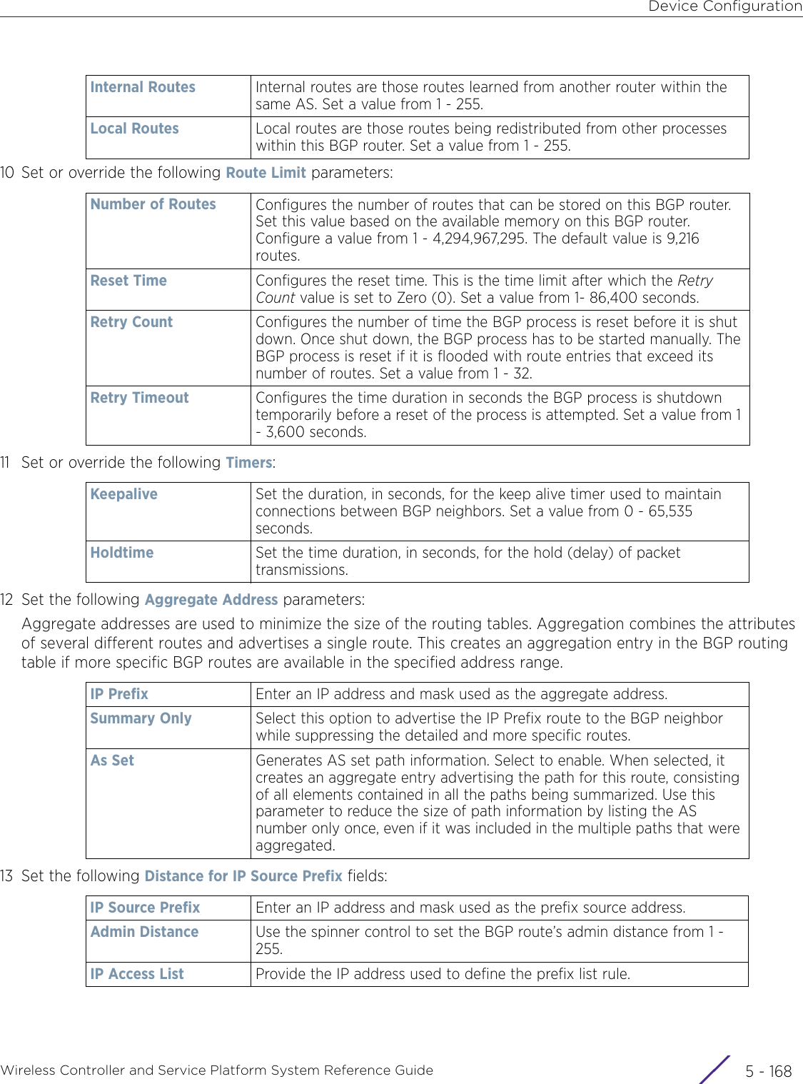
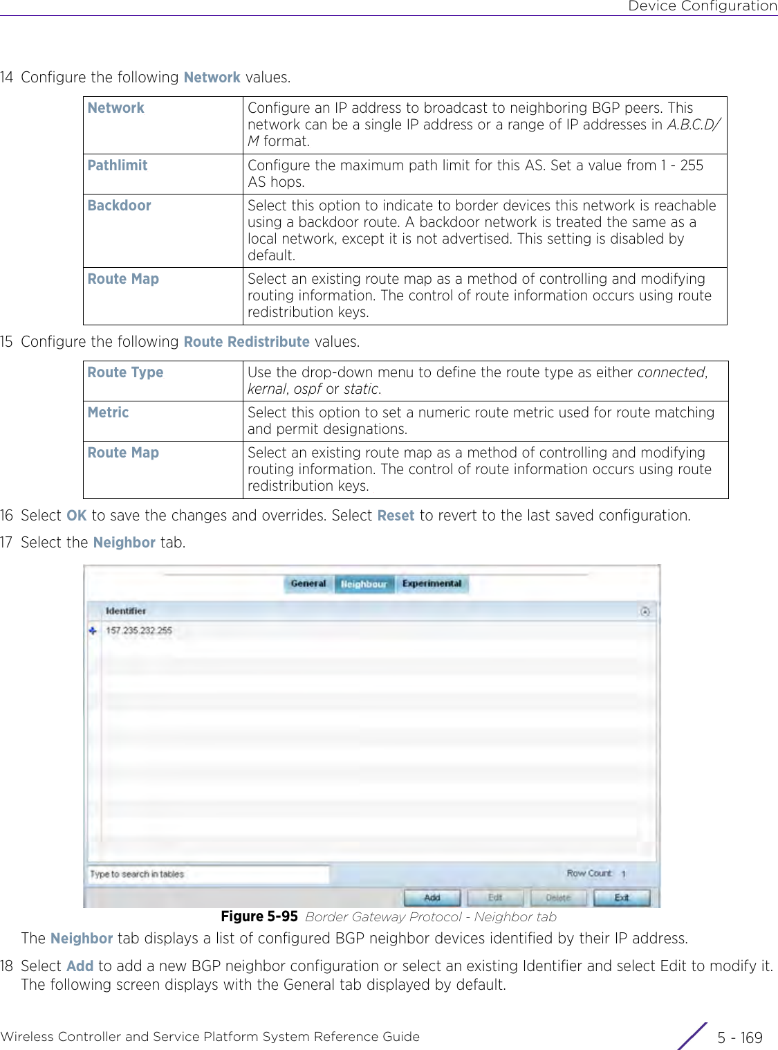
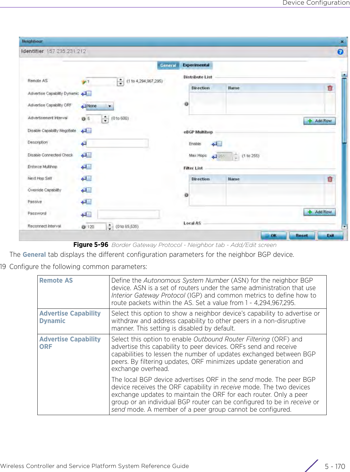
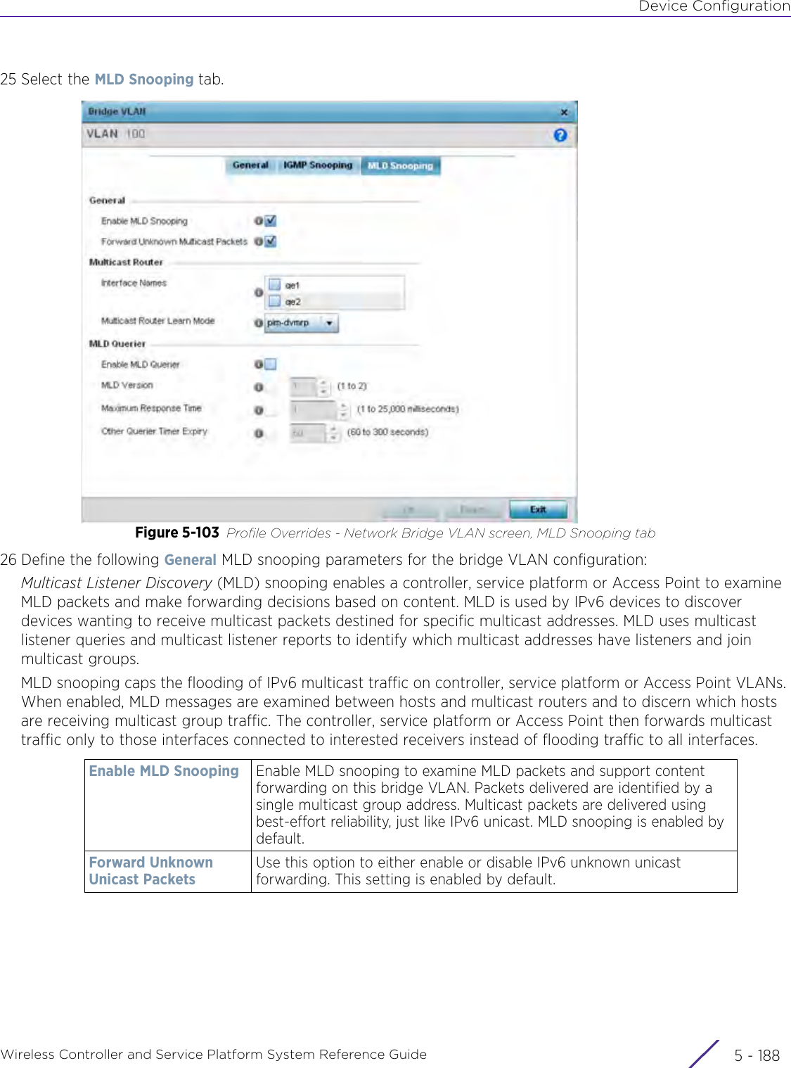
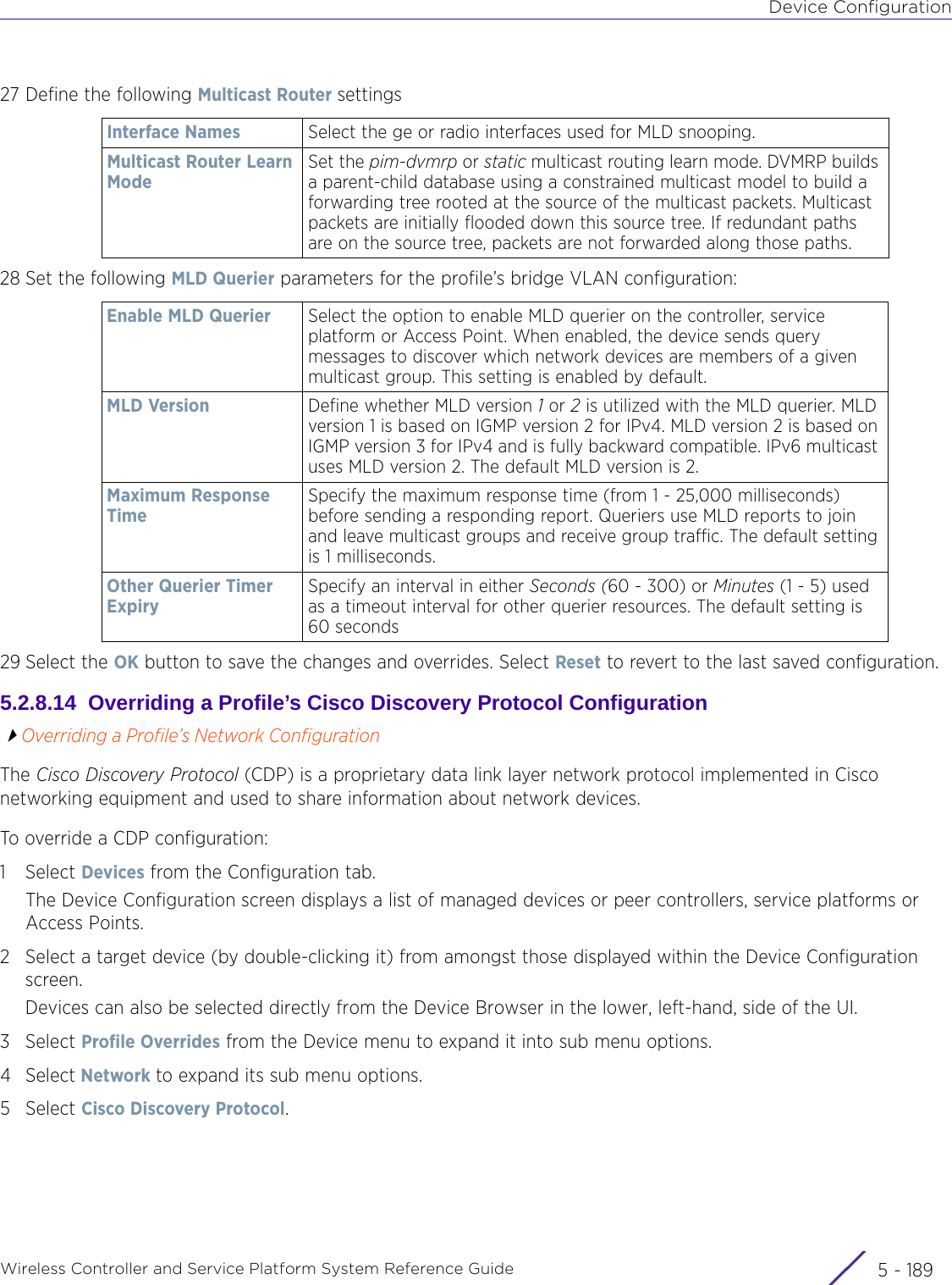
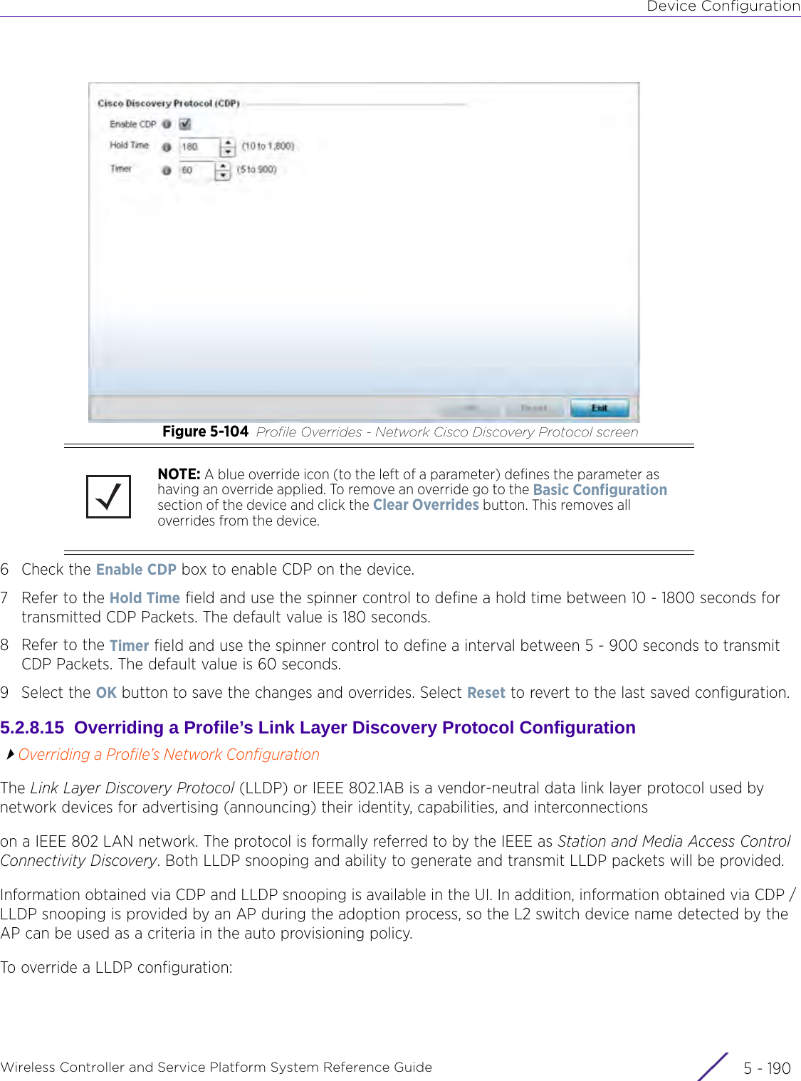
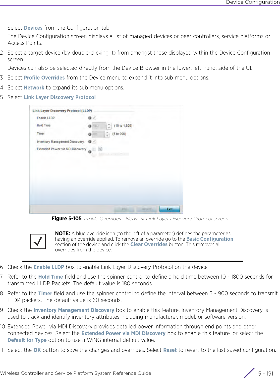
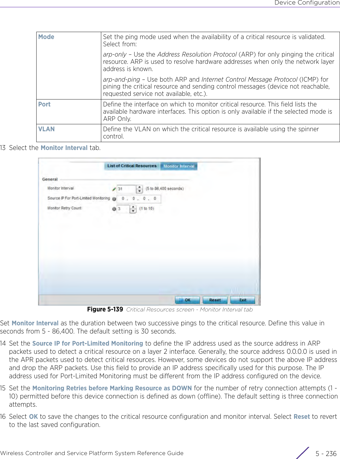
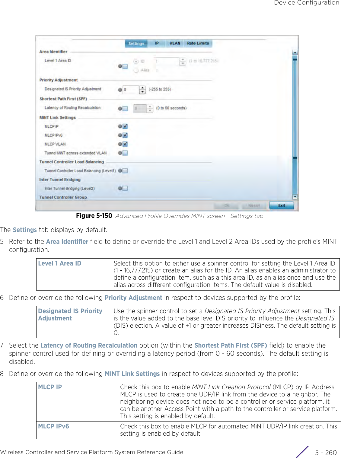
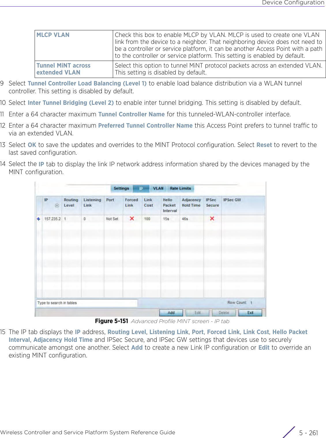
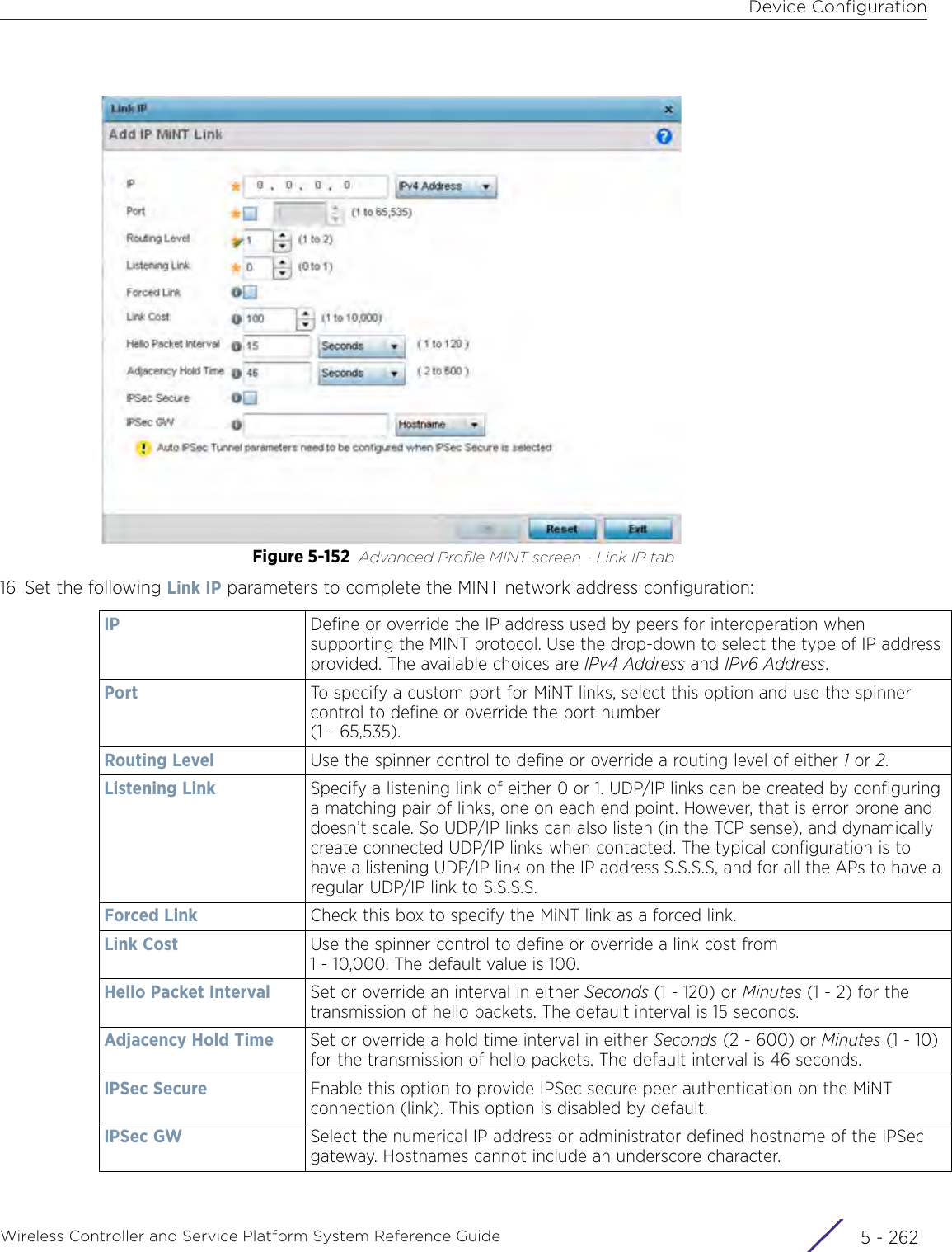
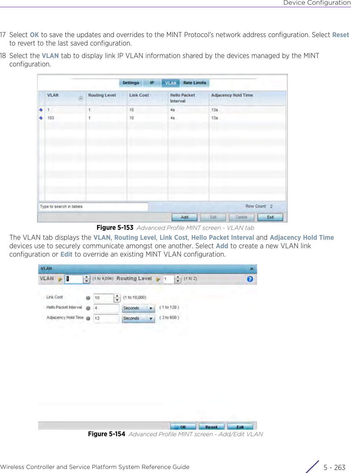
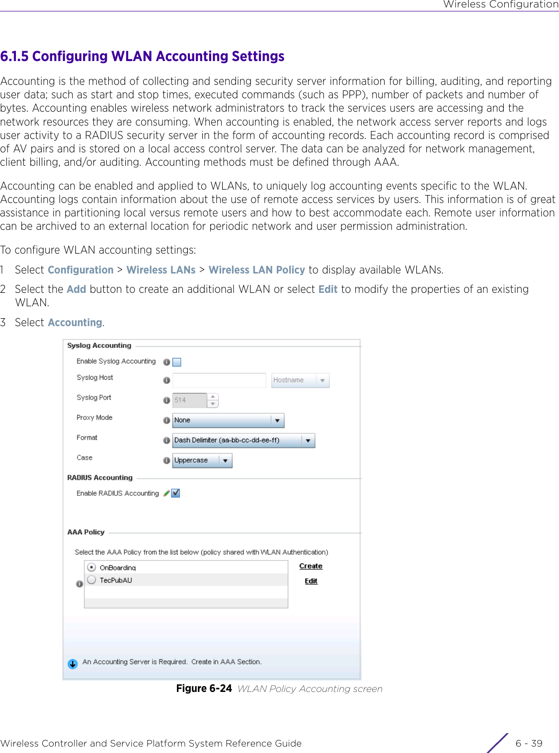
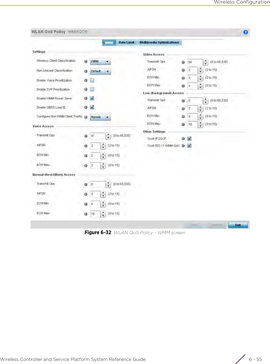
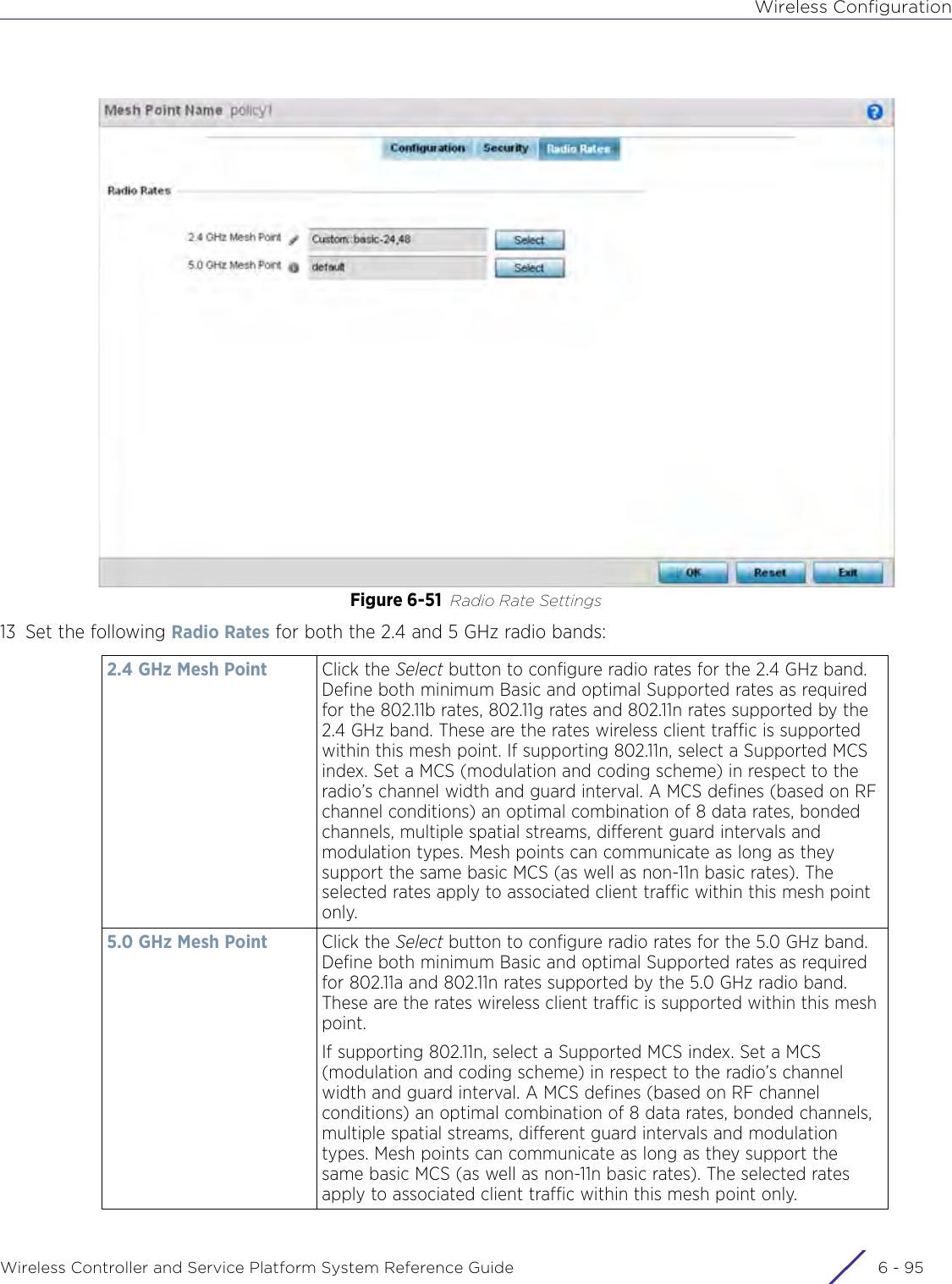
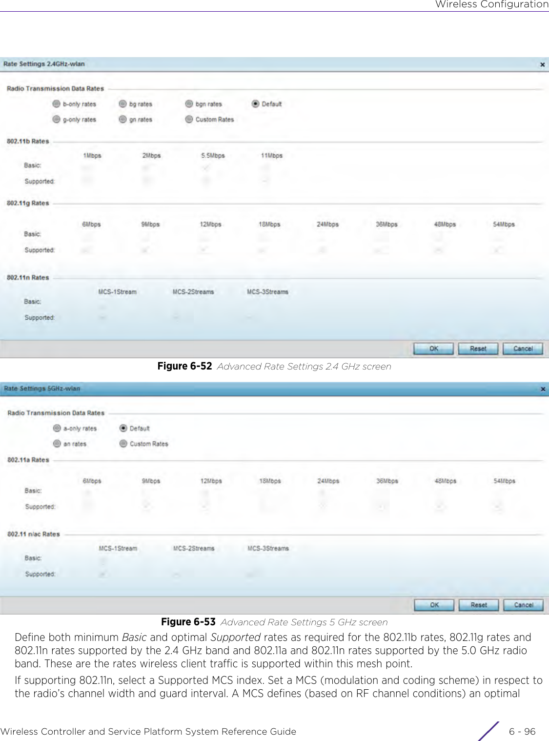
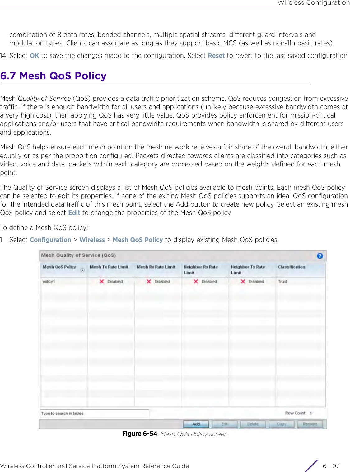
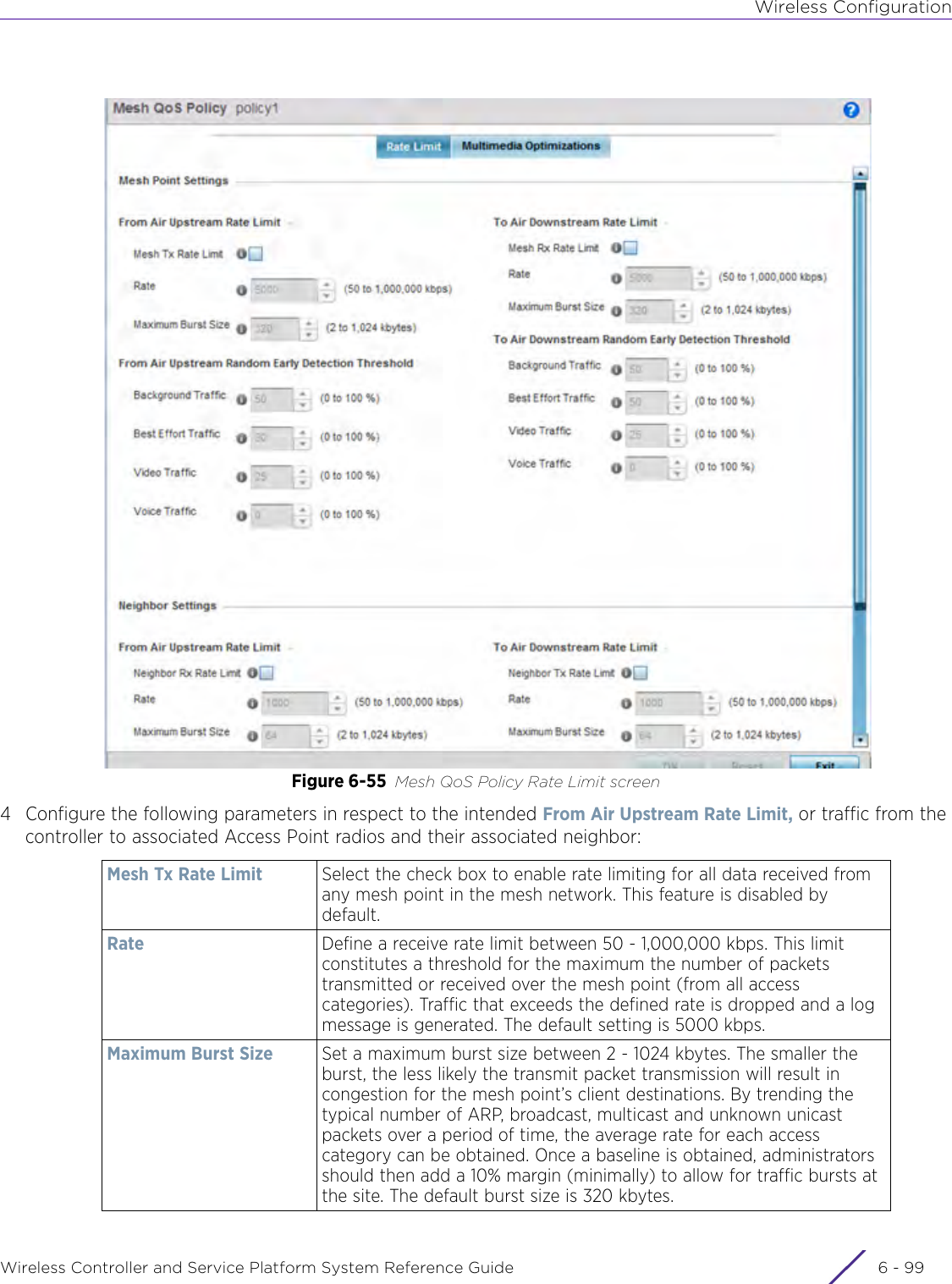
![DashboardWireless Controller and Service Platform System Reference Guide 4 - 30When all configuration fields are complete, select Start to start the wireless client debug capture. If information is being sent to the screen it displays in the Live Wireless Debug Events section. If the data is being sent to a file, Select Debug MessagesSelect All Debug Messages, to display all wireless client debug information for the selected wireless clients on the current RF Domain. Choose Selected Debug Messages to specify which types of wireless client debug messages to display. If the Selected Debug Messages radio button is selected, you can display information for any combination of the following:- 802.11 Management- EAP- Flow Migration- RADIUS- System Internal- WPA/WPA2Wireless Clients Select All Wireless Clients to display debug information for all wireless clients currently associated to the current RF Domain. Choose Selected Wireless Clients to display information only for specific wireless clients (between 1 and 3). If the Selected Wireless Clients radio button is selected enter the MAC address for up to three wireless clients. The information displayed or logged to the file will only be from the specified wireless clients.Duration of Message CaptureUse the spinner controls to select how long to capture wireless client debug information. This can range between 1 second and 24 hours, with the default value being 1 minute.Maximum Events Per Wireless ClientUse the spinner controls to select the maximum number of debug messages displayed per wireless client. Set the number of messages from 1 - 9999 events with the default value being 100 events.File Location When the Send Data To field is set to File, the File Location configuration displays below the configuration section. If Basic is selected, enter the URL in the following format:URL Syntax:tftp://<hostname|IP>[:port]/path/fileftp://<user>:<passwd>@<hostname|IP>[:port]/path/file IPv6 URL Syntax:tftp://<hostname|[IPv6]>[:port]/path/fileftp://<user>:<passwd>@<hostname|[IPv6]>[:port]/path/fileIf Advanced is selected, configure the Target, Port, Host/IP, User, Password and optionally the path for the wireless client debug log file you wish to create.Live Wireless Debug EventsWhen the Send Data To field is set to Screen, this area displays live debug information for connected wireless clients in the selected RF Domain.](https://usermanual.wiki/Extreme-Networks/AP3917E.WiNG-5-9-1-System-Reference-Guide-Part-1/User-Guide-3831157-Page-70.png)