Extreme Networks AP3917E Wireless 802.11 a/ac+b/g/n Access Point User Manual ExtremeWireless V10 41 06 User Guide
Extreme Networks, Inc. Wireless 802.11 a/ac+b/g/n Access Point ExtremeWireless V10 41 06 User Guide
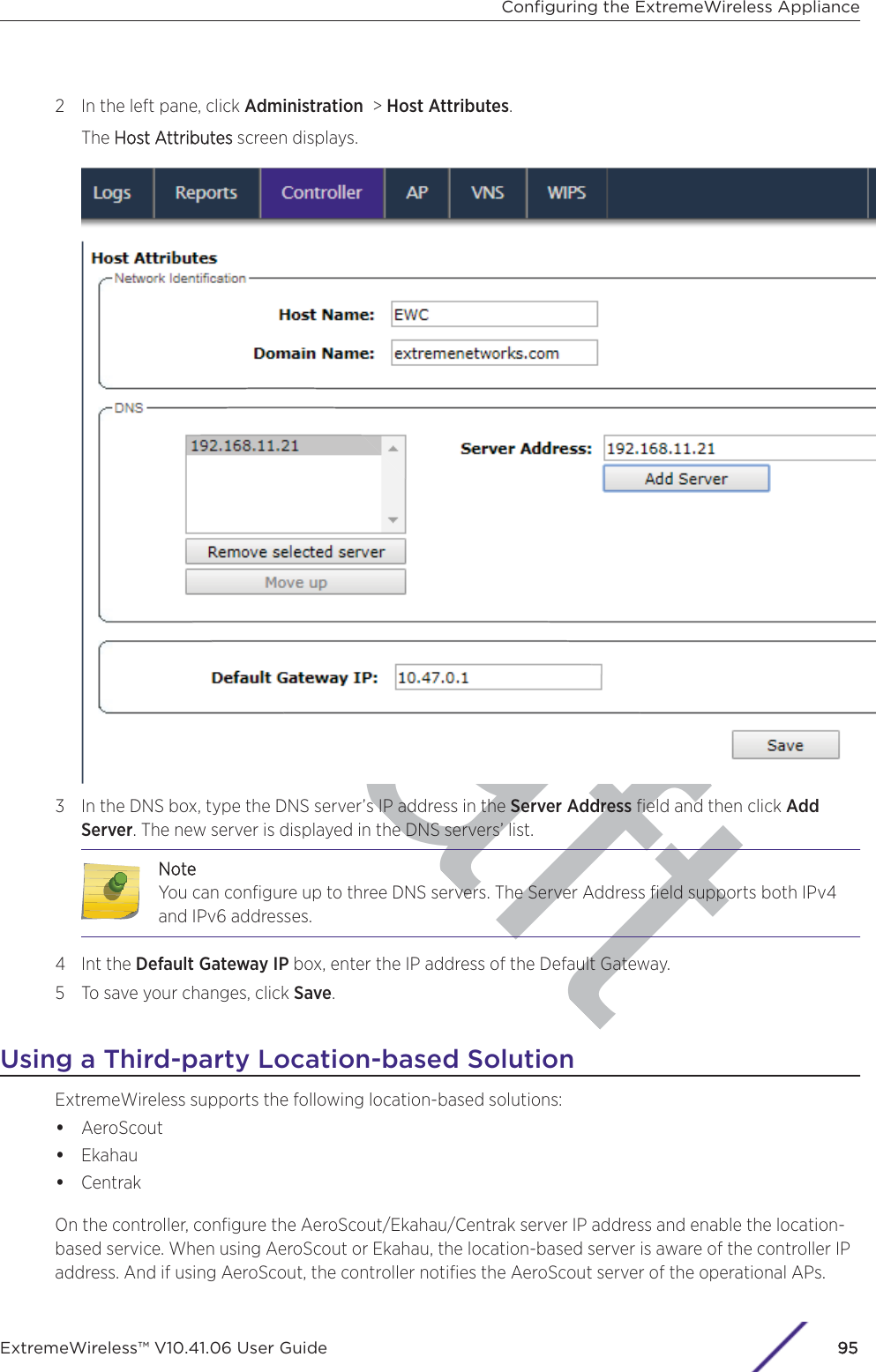
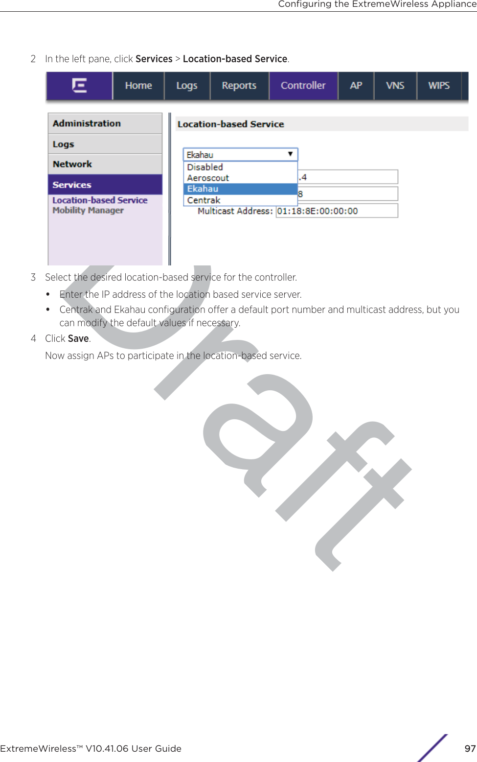
Contents
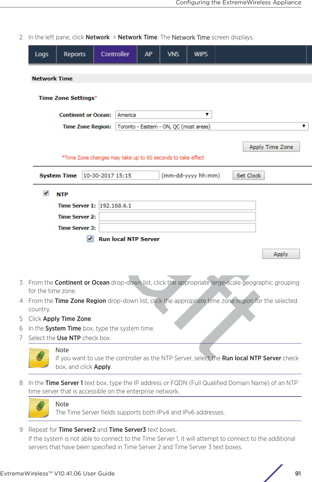
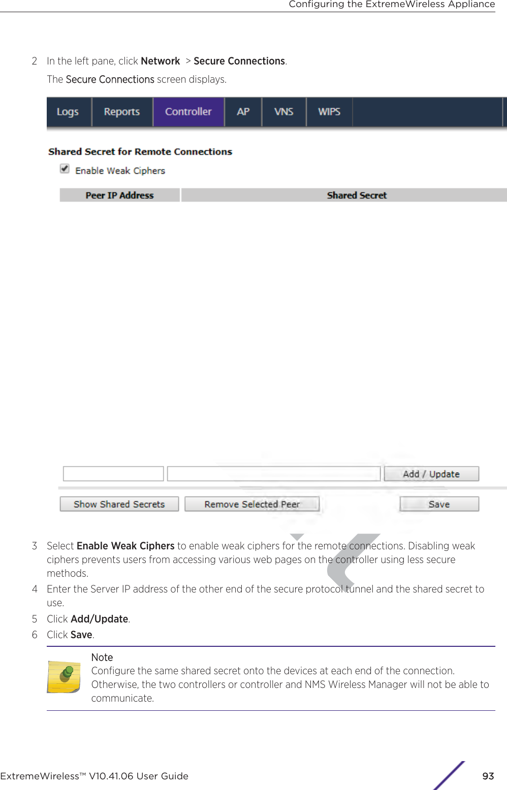
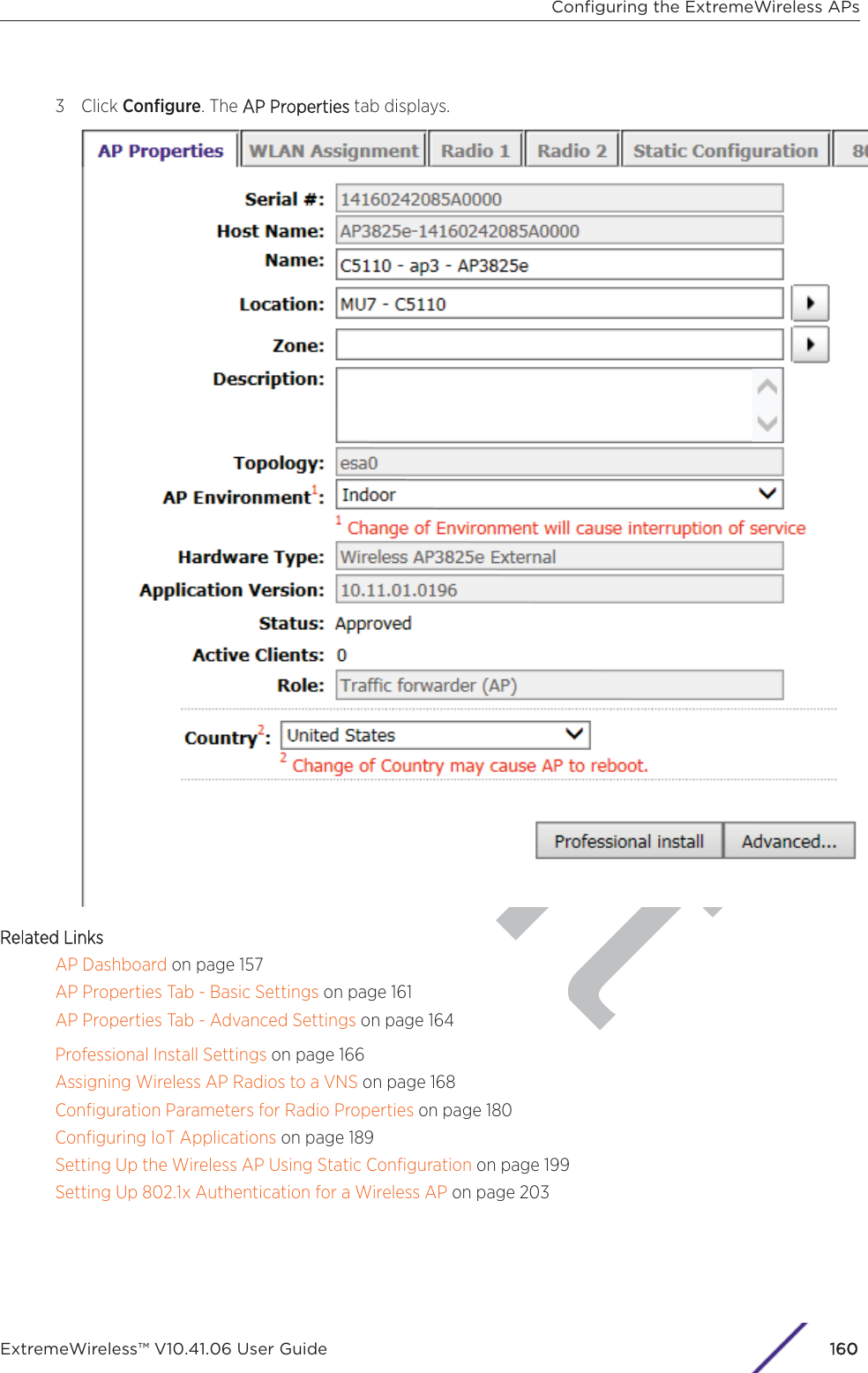
- 1. User Manual-AP3917e
- 2. User Manual-AP7662
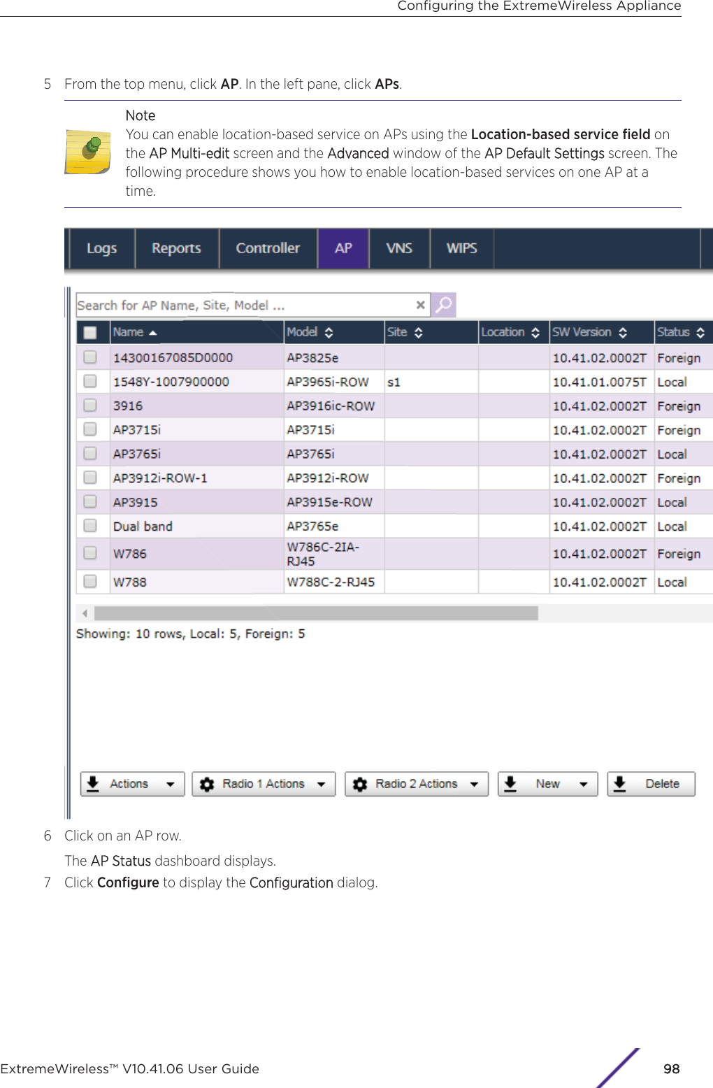
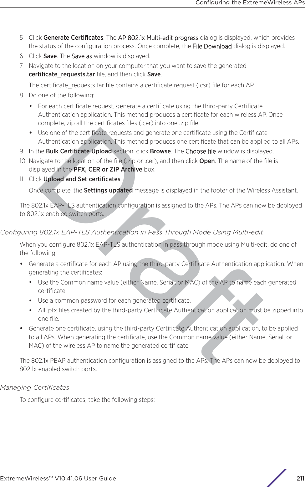
- 3. User Manual-AP3917e R1
- 4. User Manual-AP7662 R1
- 5. WiNG 5.9.1 System Reference Guide Part 1
- 6. WiNG 5.9.1 System Reference Guide Part 2
- 7. WiNG 5.9.1 System Reference Guide Part 3
- 8. WiNG 5.9.1 System Reference Guide Part 4
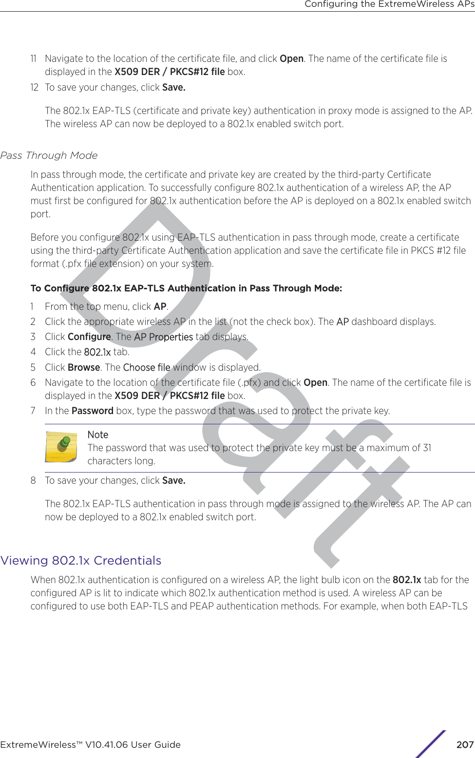
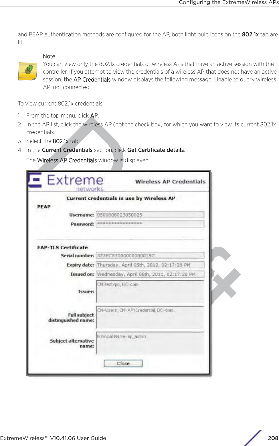
- 9. WiNG 5.9.1 CLI Reference Guide Part 1
- 10. WiNG 5.9.1 CLI Reference Guide Part 2
- 11. Extreme Wireless V10.41.06 User Guide Part 1
- 12. AP3917 User Manual
- 13. AP7662 User Manual
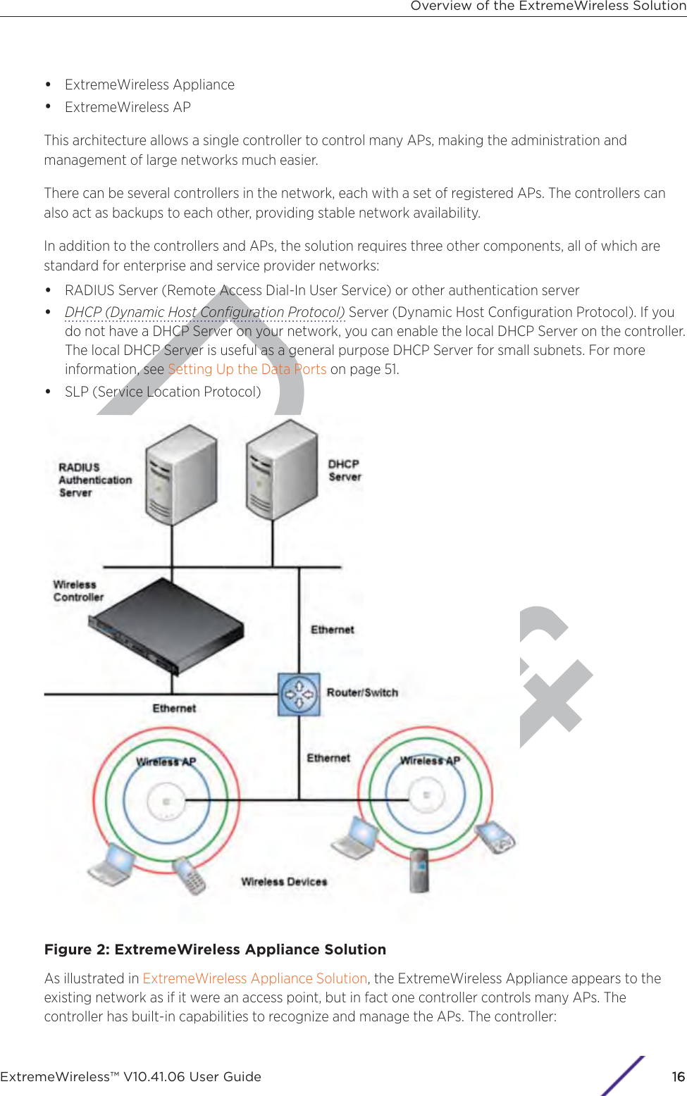
Extreme Wireless V10.41.06 User Guide Part 1
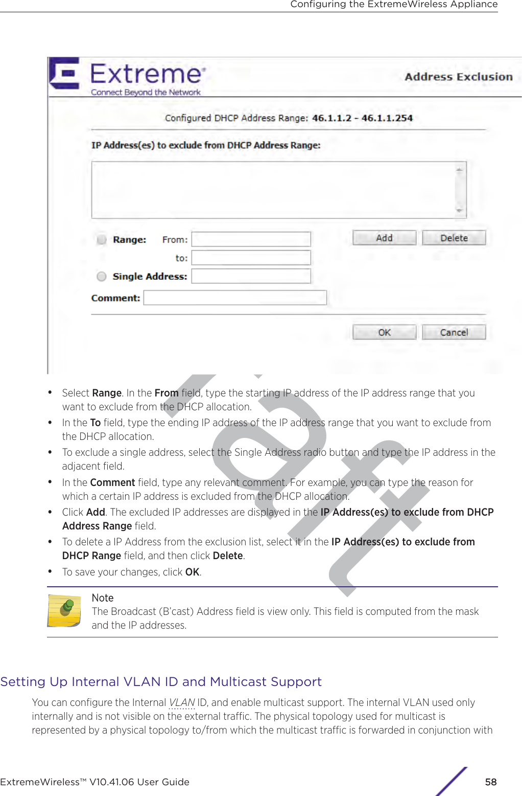
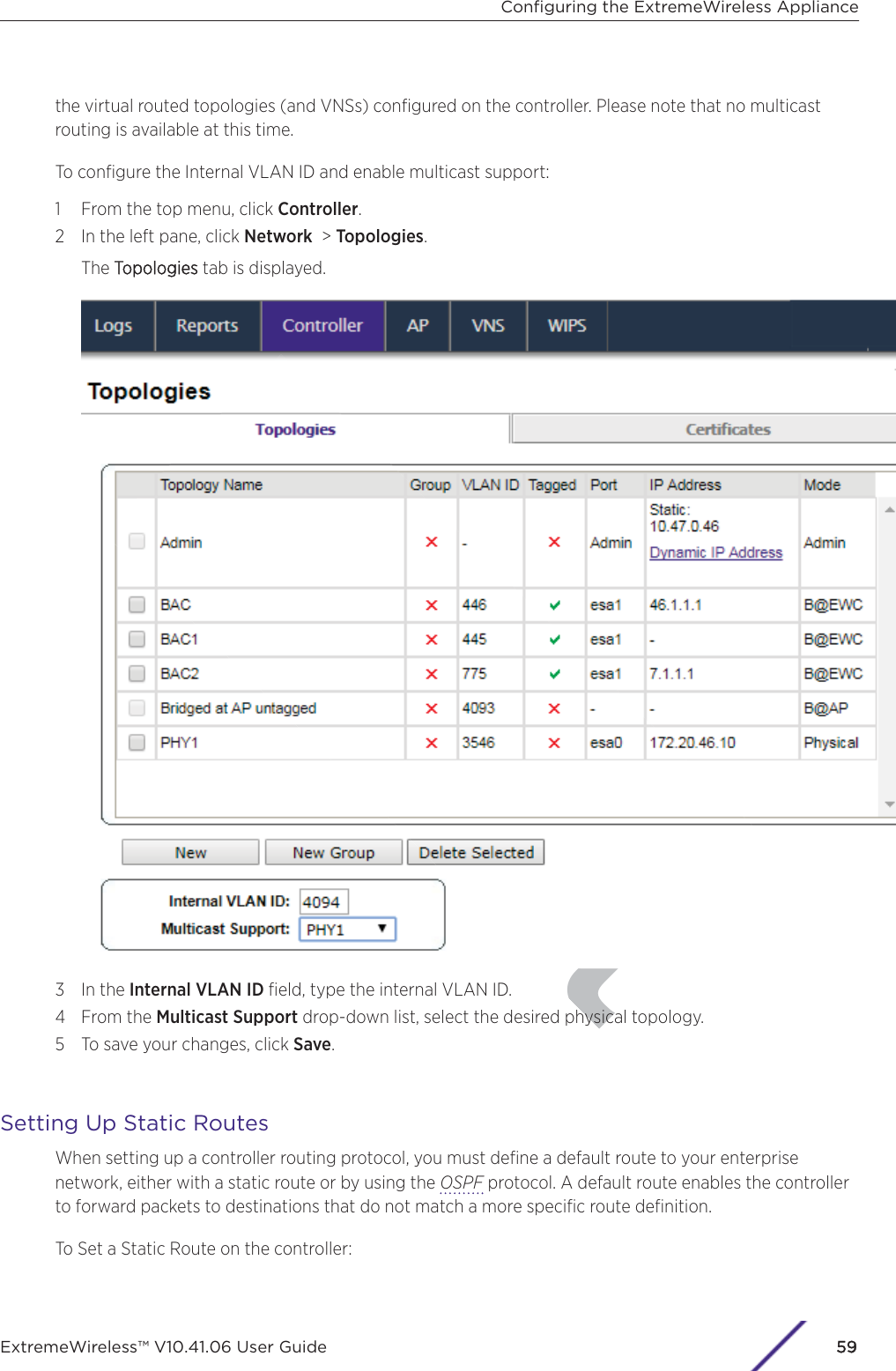
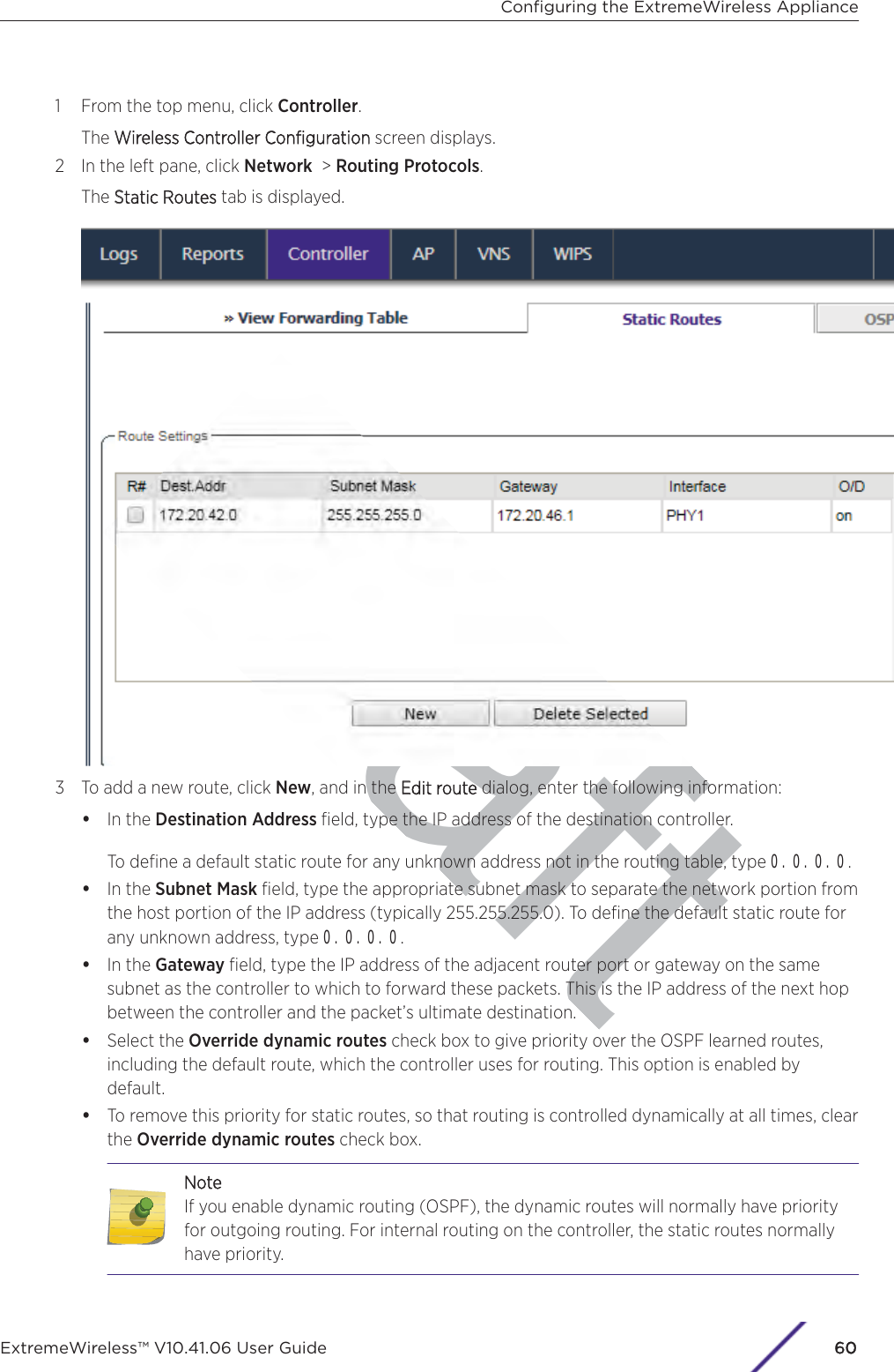
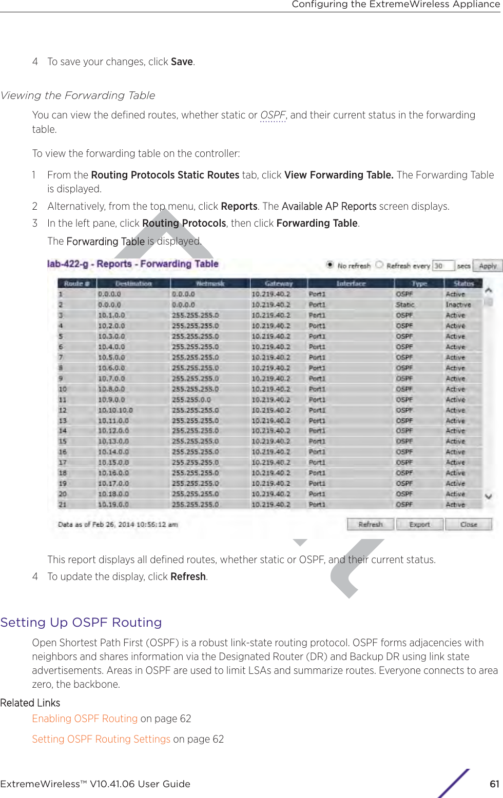
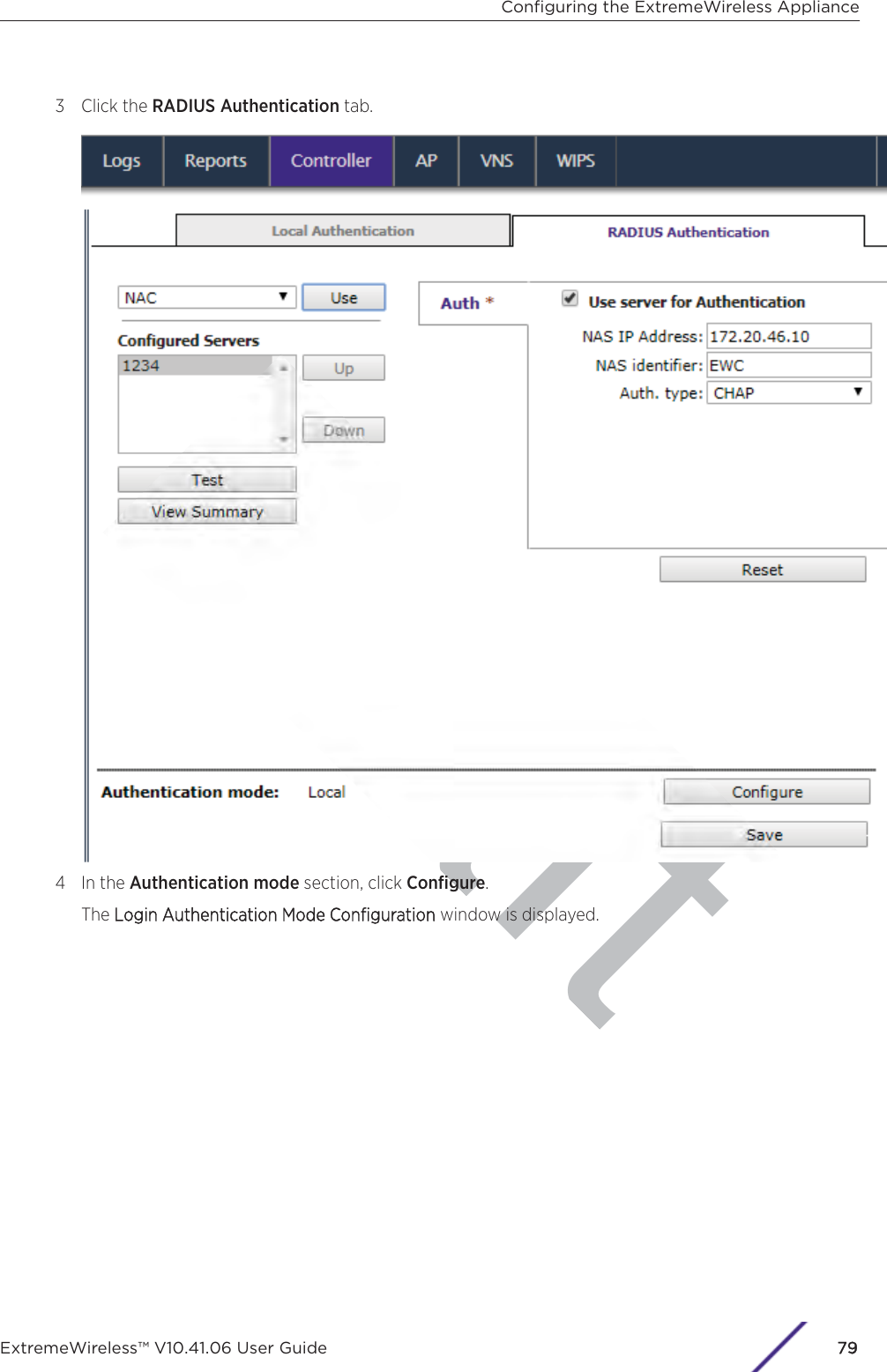
![DraftPrefaceThis section discusses the conventions used in this guide, ways to provide feedback, additional help, andother Extreme Networks publications.Text ConventionsThe following tables list text conventions that are used throughout this guide.Table 1: Notice IconsIIcon Notice Type Alerts you to...General Notice Helpful tips and notices for using the product.Note Important features or instructions.Caution Risk of personal injury, system damage, or loss of data.Warning Risk of severe personal injury.New!New Content Displayed next to new content. This is searchable text within the PDF.Table 2: Text ConventionsConvention DescriptionScreen displays This typeface indicates command syntax, or represents information as it appears on thescreen.The words eenter andtypeWhen you see the word “enter” in this guide, you must type something, and then pressthe Return or Enter key. Do not press the Return or Enter key when an instructionsimply says “type.”[Key] names Key names are written with brackets, such as [Return] or [Esc]. If you must press twoor more keys simultaneously, the key names are linked with a plus sign (+). Example:Press [Ctrl]+[Alt]+[Del]Words in italicized type Italics emphasize a point or denote new terms at the place where they are defined inthe text. Italics are also used when referring to publication titles.Safety InformationDangers•Replace the power cable immediately if it shows any sign of damage.•Replace any damaged safety equipment (covers, labels and protective cables) immediately.ExtremeWireless™ V10.41.06 User Guide7](https://usermanual.wiki/Extreme-Networks/AP3917E.Extreme-Wireless-V10-41-06-User-Guide-Part-1/User-Guide-3831181-Page-7.png)
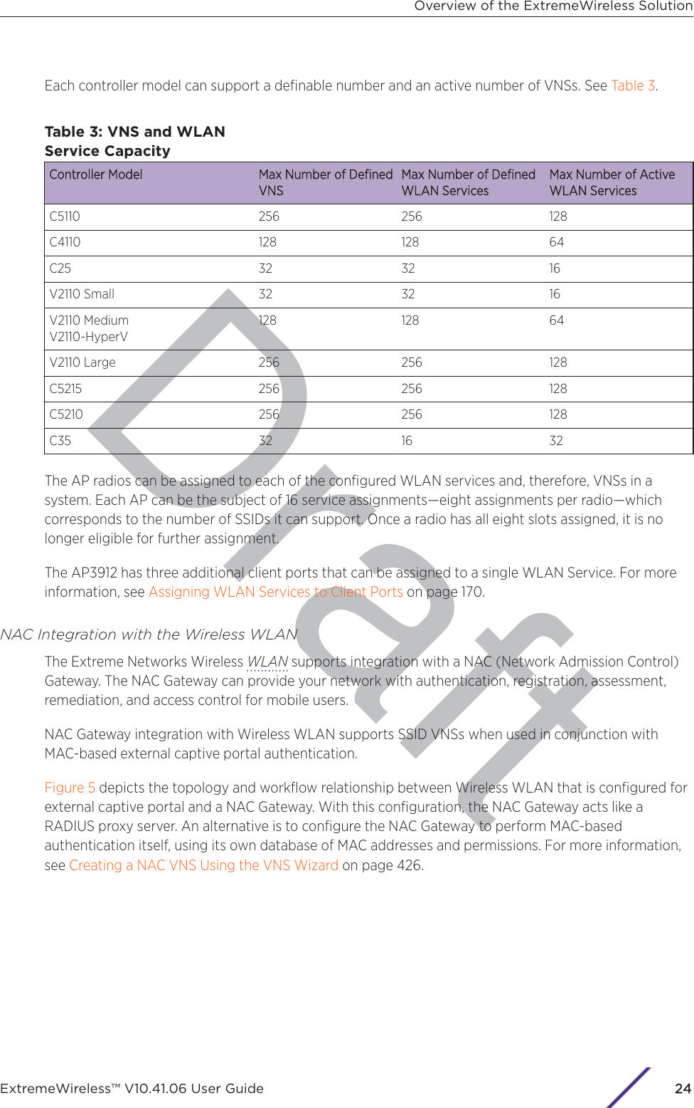
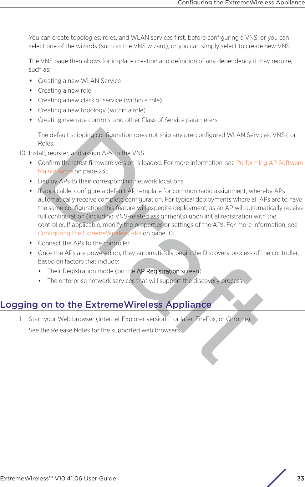
![Draftthe controller to avoid network interruptions. For more information, see Configuring NetworkTime on page 89.e Apply an activation key file. If an activation key is not applied, the controller functions with somefeatures enabled in demonstration mode. Not all features are enabled in demonstration mode.For example, mobility is not enabled and cannot be used.CCautionWhenever the licensed region changes on the ExtremeWireless Appliance, all APs arechanged to Auto Channel Select to prevent possible infractions to local RF regulatoryrequirements. If this occurs, all manually configured radio channel settings will belost.Installing the new license key before upgrading will prevent the ExtremeWirelessAppliance from changing the licensed region, and in addition, manually configuredchannel settings will be maintained. For more information, see the ExtremeWirelessMaintenance Guide.5 Configure the controller for remote access:a Set up an administration station (laptop) on subnet 192.168.10.0/24. By default, the controller'sManagement interface is configured with the static IP address 192.168.10.1.b Configure the controller’s management interface.c Configure the data interfaces.d Set up the controller on the network by configuring the physical data ports.e Configure the routing table.f Configure static routes or OSPF (Open Shortest Path First) parameters, if appropriate to thenetwork.For more information, see Configuring the ExtremeWireless Appliance for the First Time on page45.6 Configure the trac topologies your network must support. Topologies represent the controller’spoints of network attachment, and therefore VLANs and port assignments need to be coordinatedwith the corresponding network switch ports. For more information, see Configuring a Basic DataPort Topology on page 266.7 Configure roles. Roles are typically bound to topologies. Role application assigns user trac to thecorresponding network point.•Roles define user access rights (filtering or ACL (Access Control List))•Polices reference user's rate control profile.For more information, see Configuring Roles on page 284.8 Configure WLAN services.•Define SSID and privacy settings for the wireless link.•Select the set of APs/Radios on which the service is present.•Configure the method of credential authentication for wireless users (None, Internal CP, ExternalCP, GuestPortal, 802.1x[EAP])For more information, see Configuring WLAN Services on page 318.9 Create the VNSs.A VNS binds a WLAN Service to a Role that will be used for default assignment upon a user’snetwork attachment.Configuring the ExtremeWireless ApplianceExtremeWireless™ V10.41.06 User Guide32](https://usermanual.wiki/Extreme-Networks/AP3917E.Extreme-Wireless-V10-41-06-User-Guide-Part-1/User-Guide-3831181-Page-32.png)
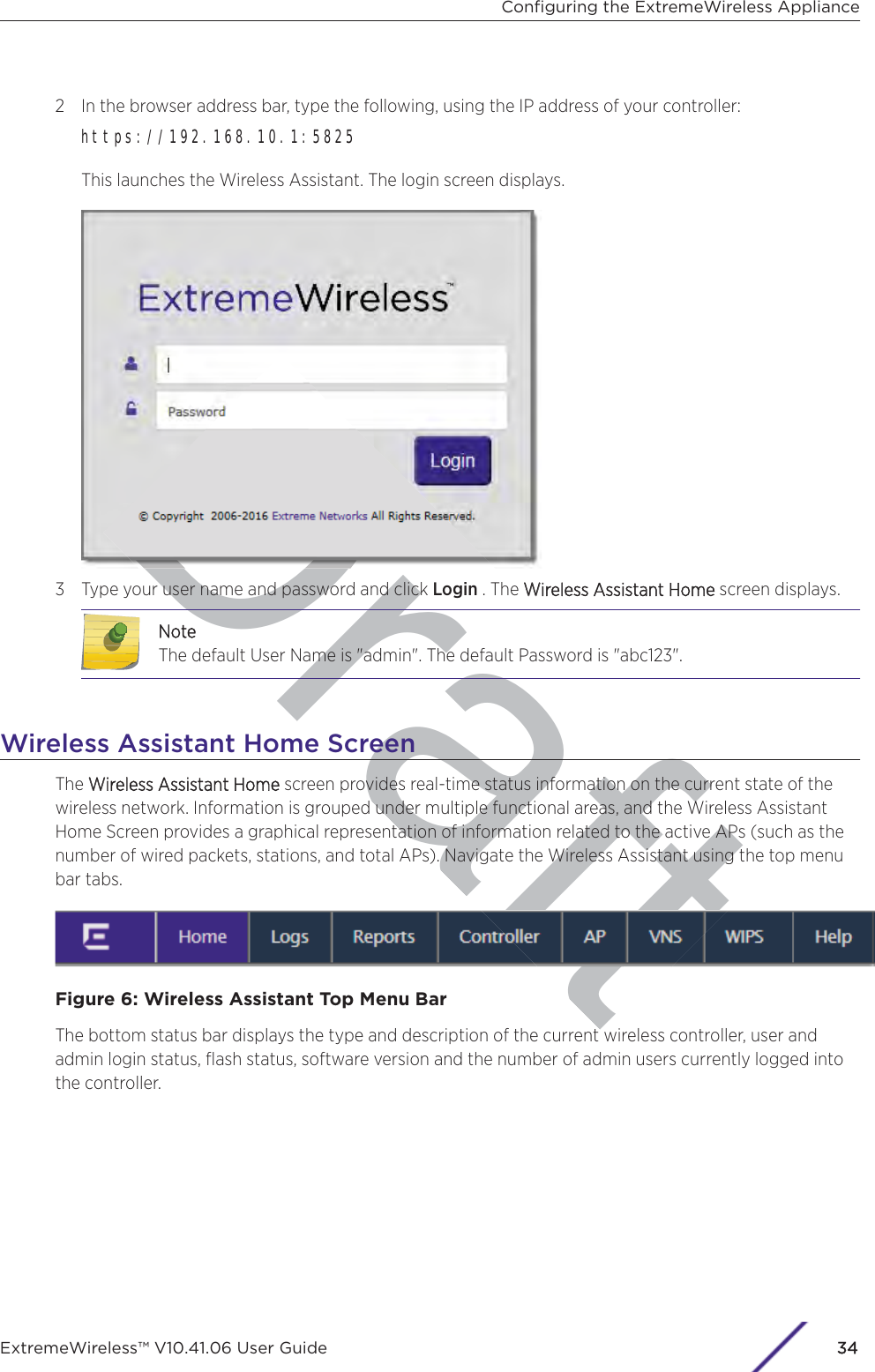
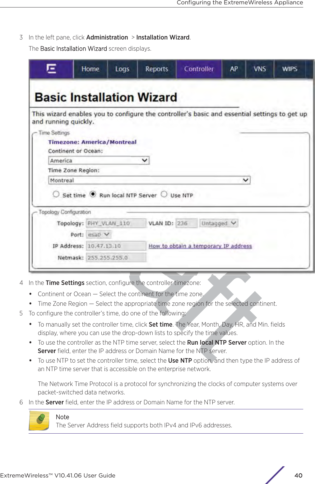
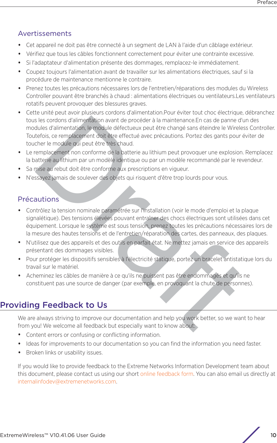
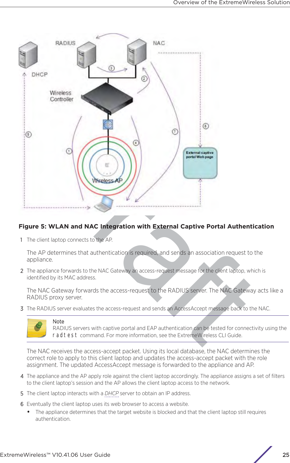
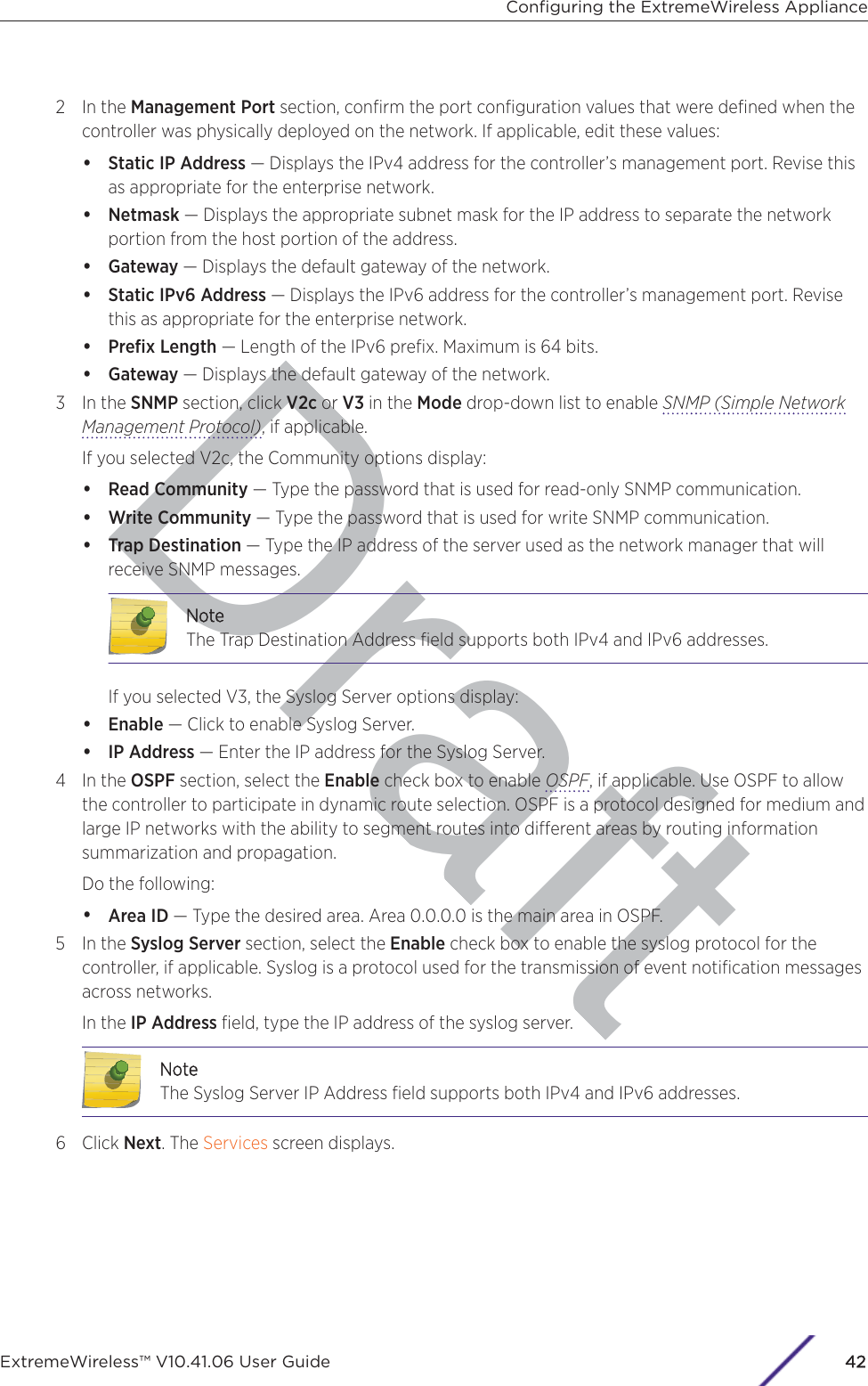
![7 In the Topology Configuration section, the physical interface of the controller data port, the IPAddress and Netmask values for the data port, and the VLAN ID display as read-only values.For information on how to obtain a temporary IP address from the network, click How to obtain atemporary IP address.8 Click Next. The Management screen displaysBasic Installation Wizard - Management ScreenThe MManagement screen displays:1 In the AP Password section, enter a password for the AP. Click Unmask to display the passwordcharacters as you type. Access Points are shipped with default passwords. You must create a newSSH Access Password here.NotePasswords can include the following characters: A-Z a-z 0-9 ~!@#$%^&*()_+|-=\{}[];<>?,.Password cannot include the following characters: / ` ' " : or a space.Configuring the ExtremeWireless ApplianceExtremeWireless™ V10.41.06 User Guide41](https://usermanual.wiki/Extreme-Networks/AP3917E.Extreme-Wireless-V10-41-06-User-Guide-Part-1/User-Guide-3831181-Page-41.png)
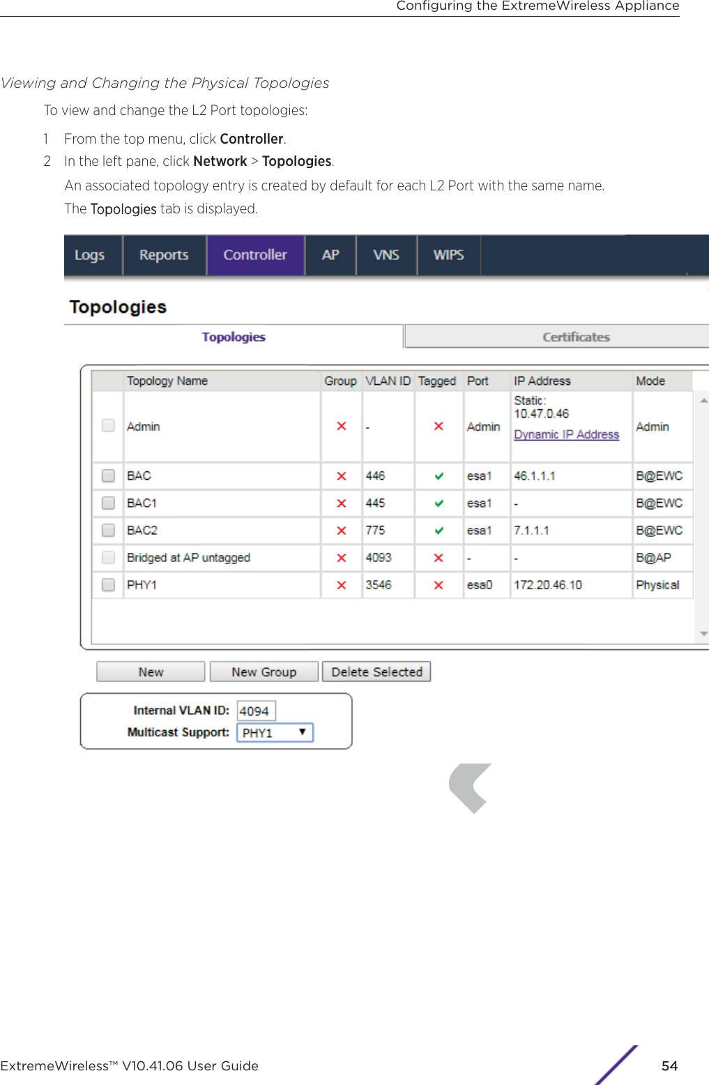
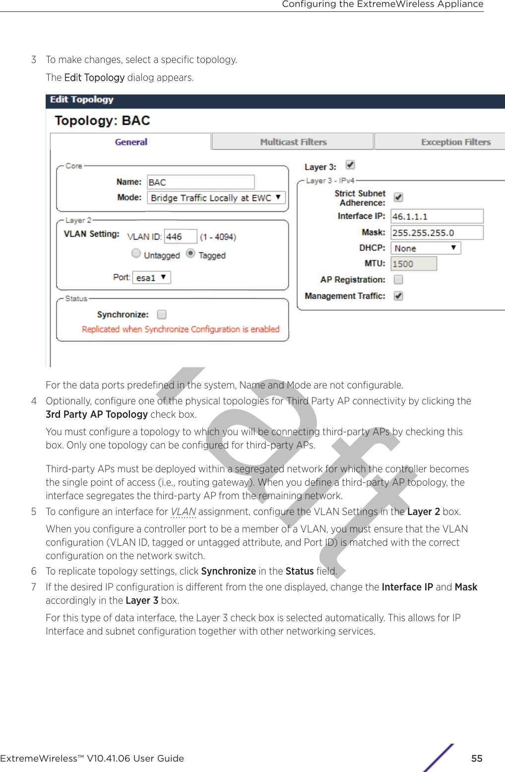
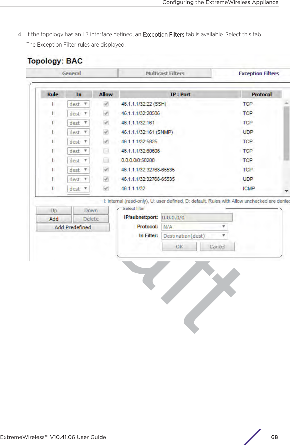
![DIf management trac is explicitly enabled for any interface, access is implicitly extended to thatinterface through any of the other interfaces (VNS). Only trac specifically allowed by the interface’sexception filter is allowed to reach the controller itself. All other trac is dropped. Exception filters aredynamically configured and regenerated whenever the system's interface topology changes (forexample, a change of IP address for any interface).Enabling management trac on an interface adds additional rules to the exception filter, which opensup the well-known IP(TCP/UDP) ports, corresponding to the HTTPS, SSH, and SNMP applications.The interface-based built-in exception policy rules, in the case of trac from wireless users, areapplicable to trac targeted directly for the topology L3 interface. For example, a filter specified by aRole may be generic enough to allow trac access to the controller's management (for example, AllowAll [*.*.*.*]). Exception policy rules are evaluated after the user's assigned filter role, as such, it ispossible that the role allows the access to management functions that the exception filter denies. Thesepackets are dropped.To enable SSH, HTTPS, or SNMP access through a physical data interface:1 From the top menu, click Controller.2 In the left pane, click Network > Topologies. The TTopologies tab is displayed.3 On the Topologies tab, click the appropriate data port topology. The EEdit Topology window displays.Configuring the ExtremeWireless ApplianceExtremeWireless™ V10.41.06 User Guide66](https://usermanual.wiki/Extreme-Networks/AP3917E.Extreme-Wireless-V10-41-06-User-Guide-Part-1/User-Guide-3831181-Page-66.png)
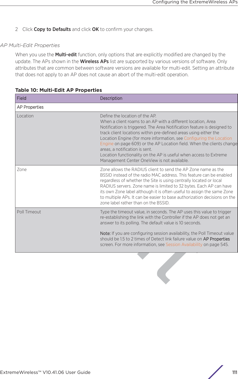
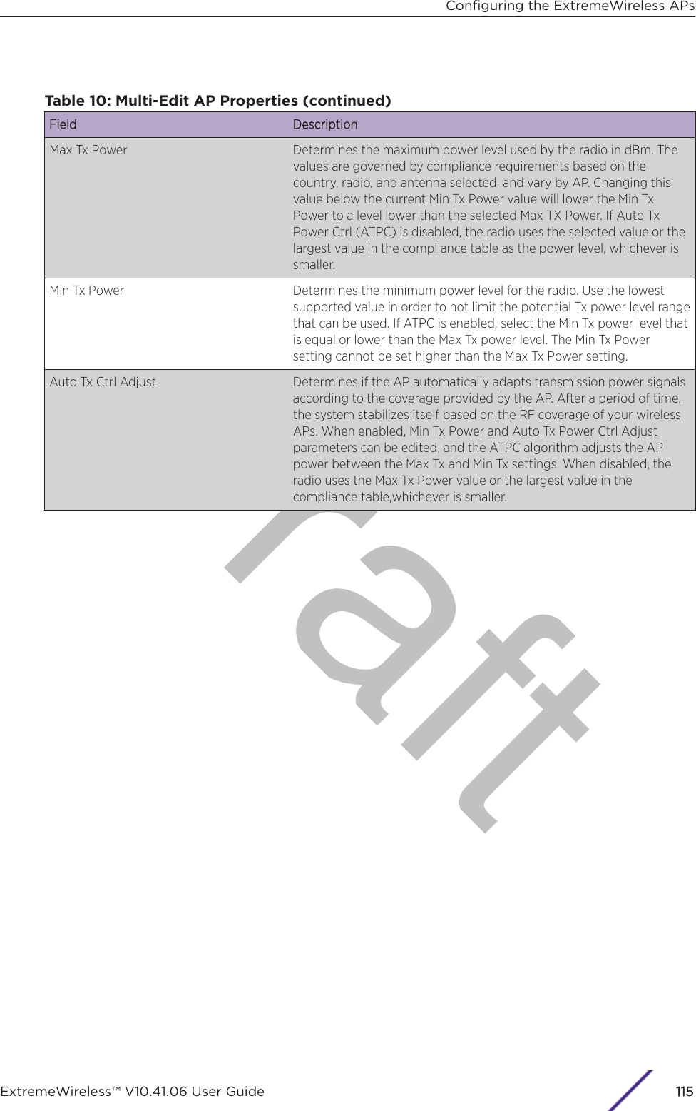
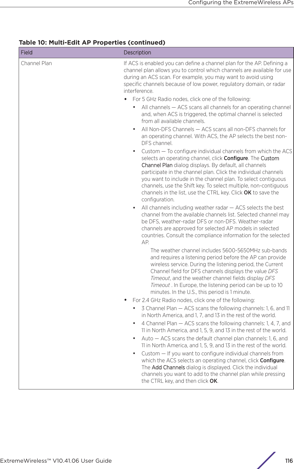
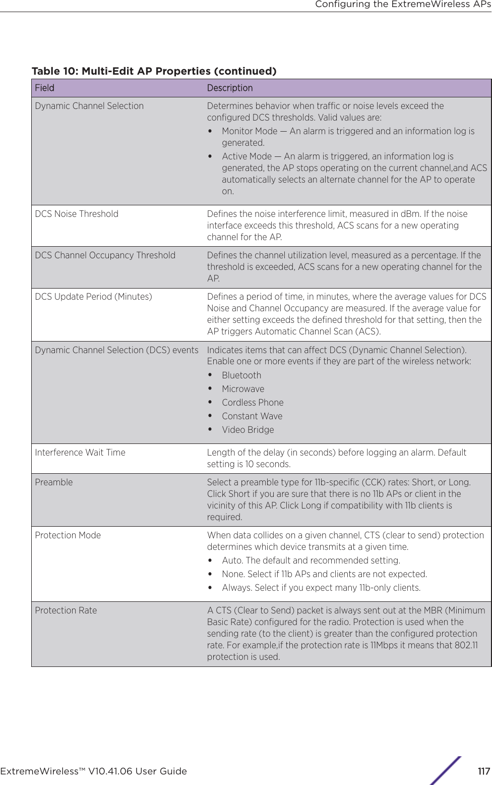
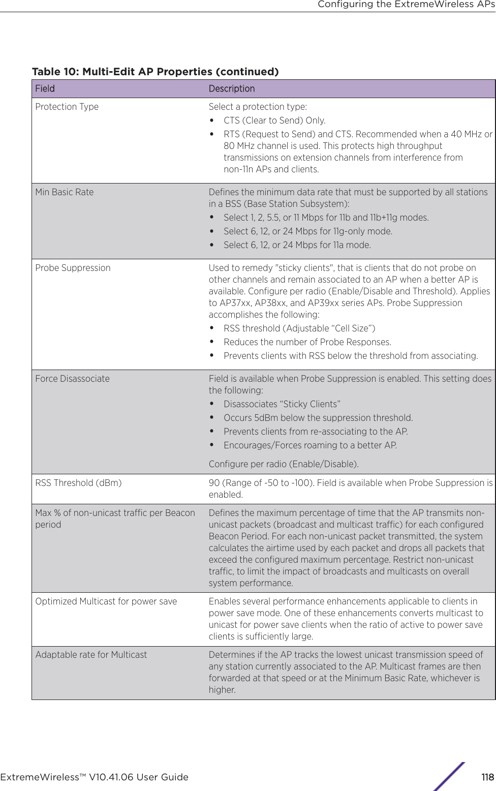
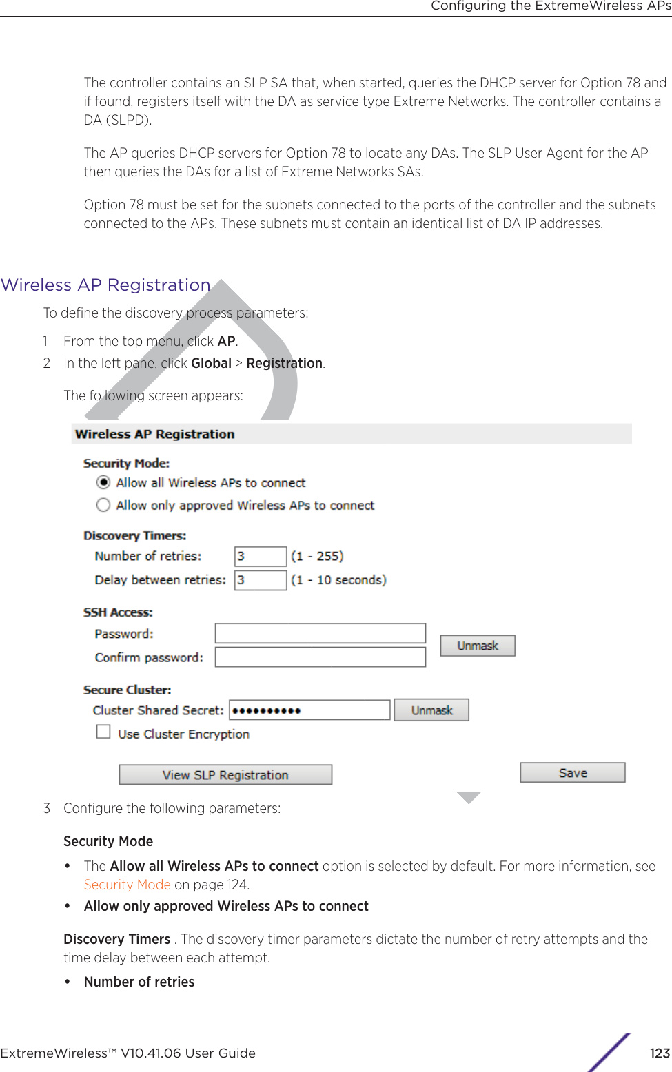
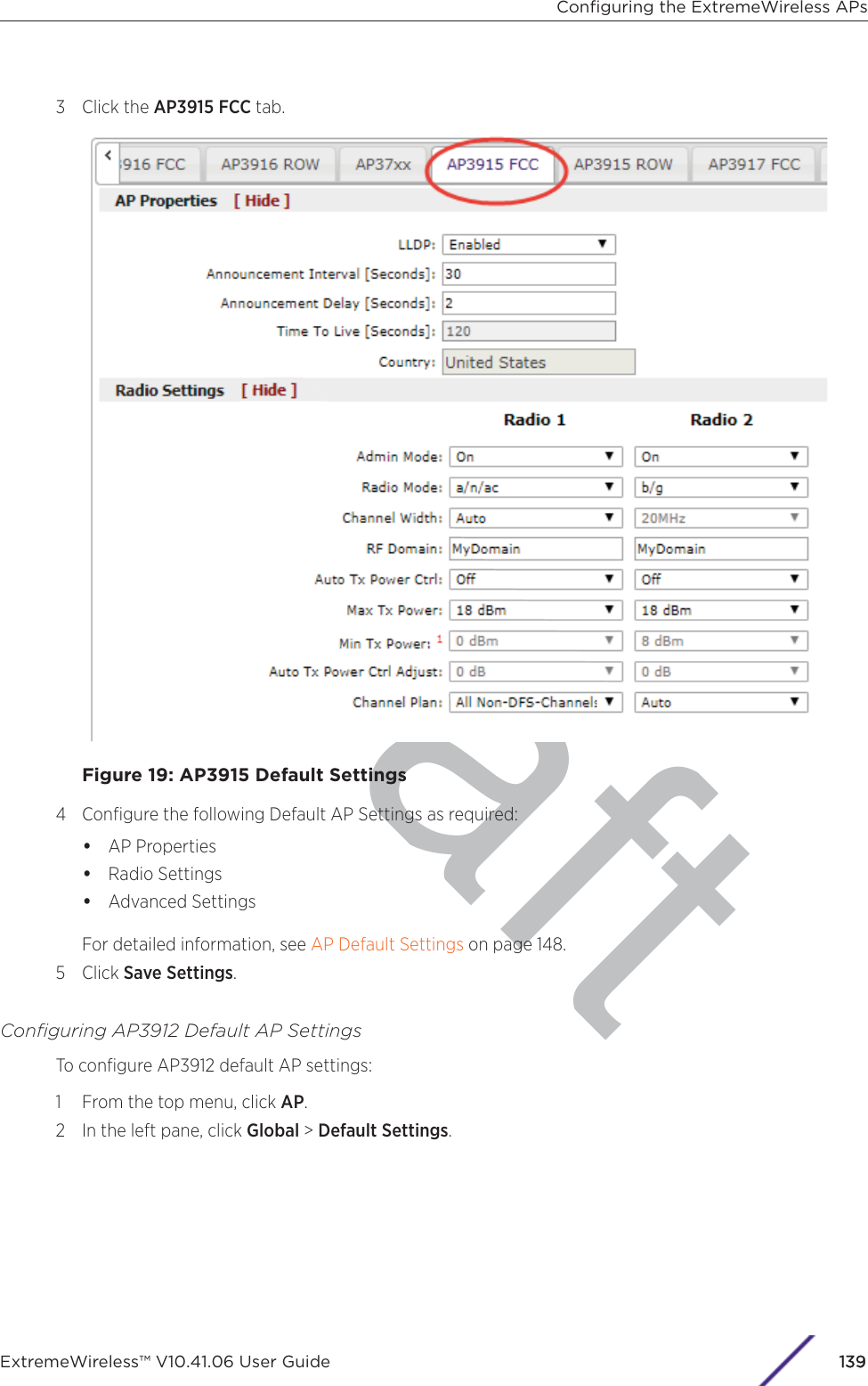
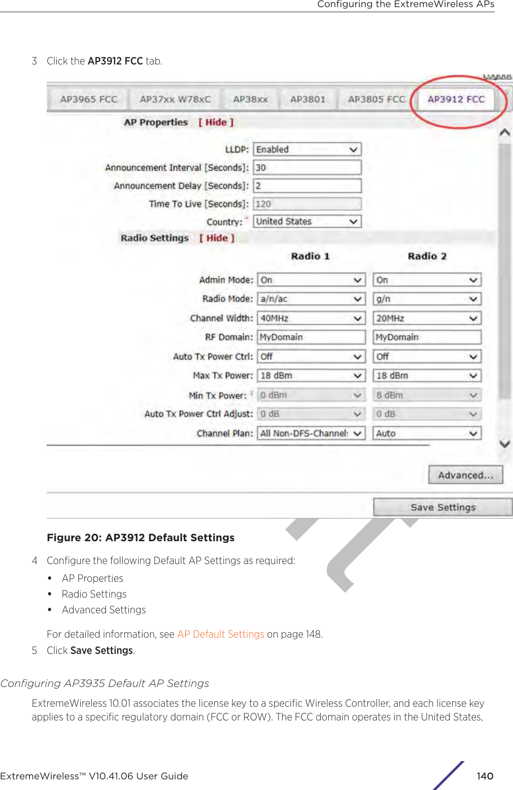
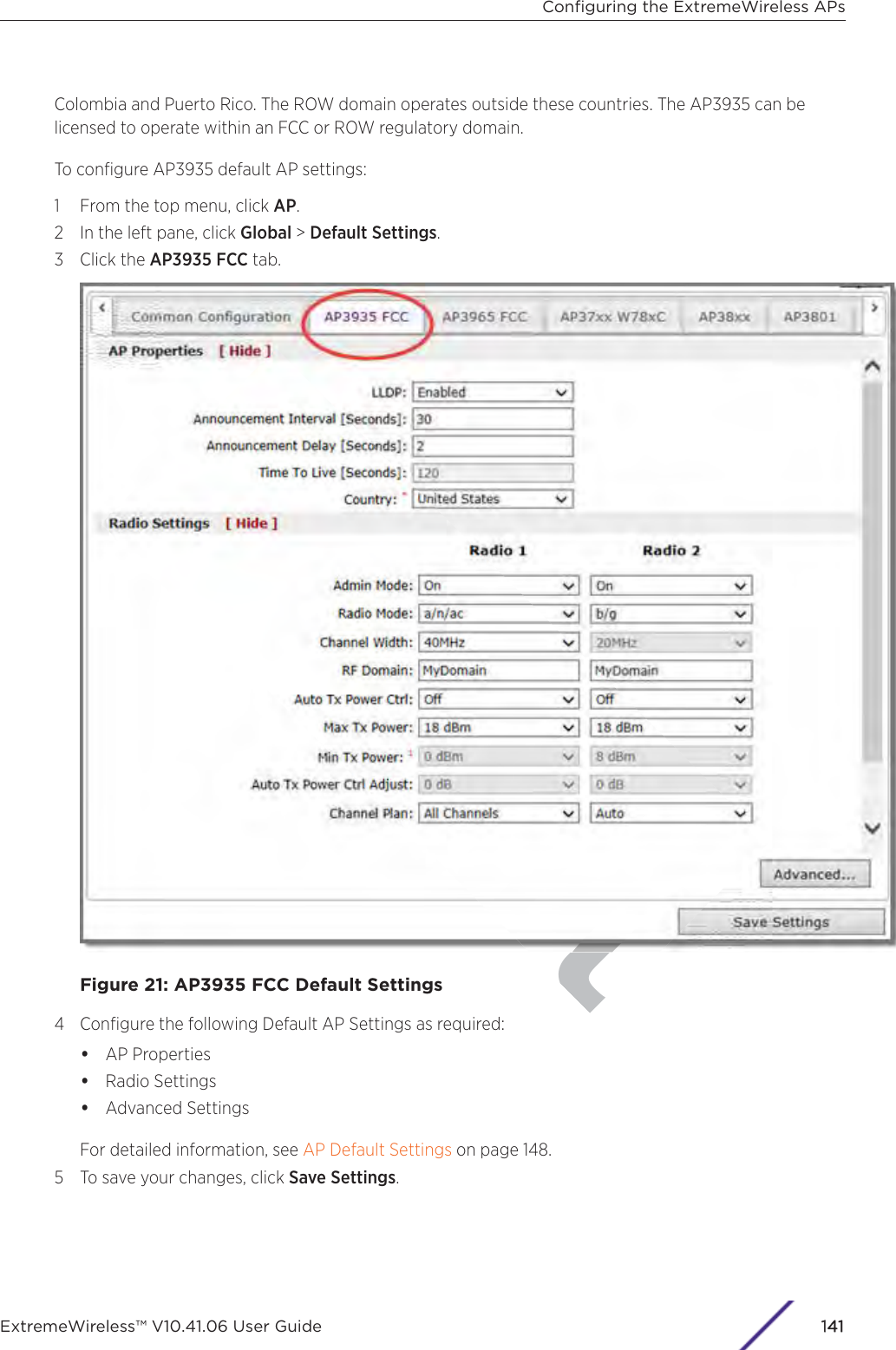
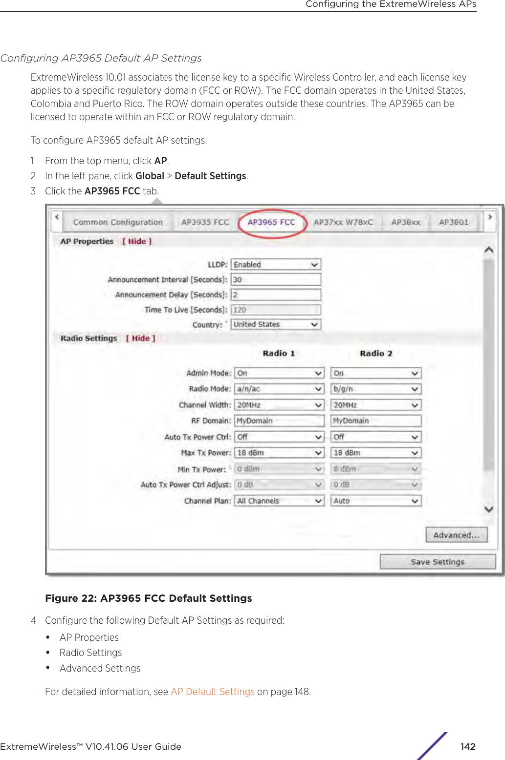
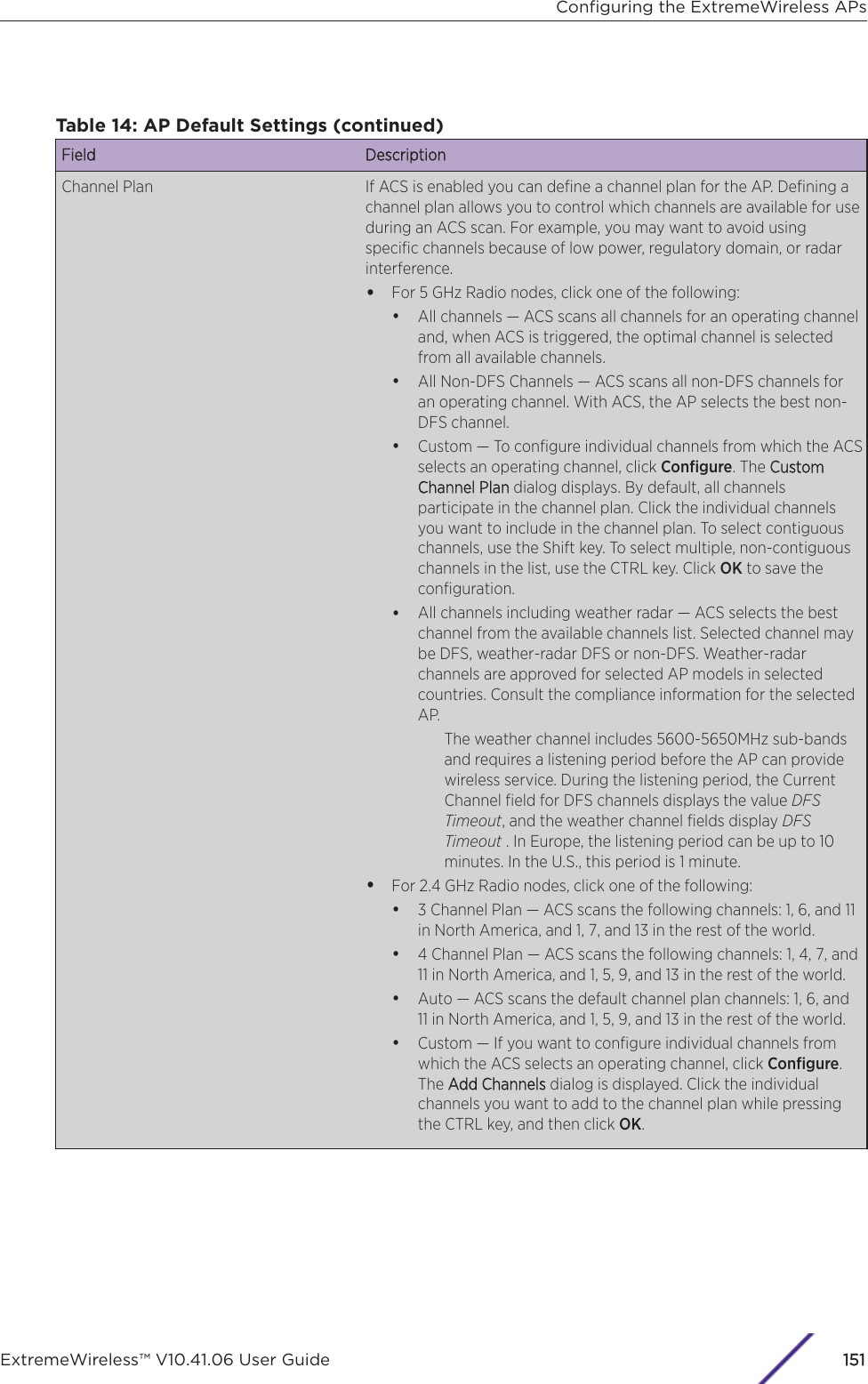
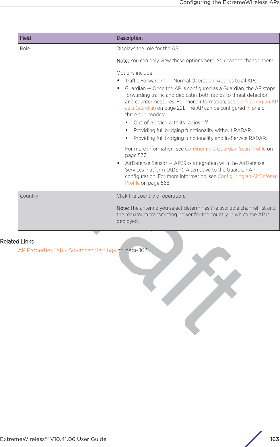
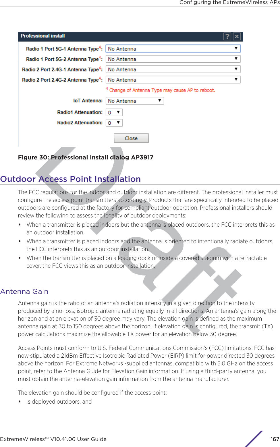
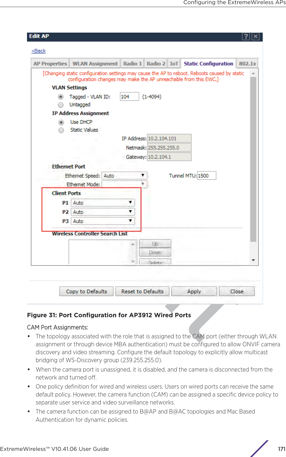
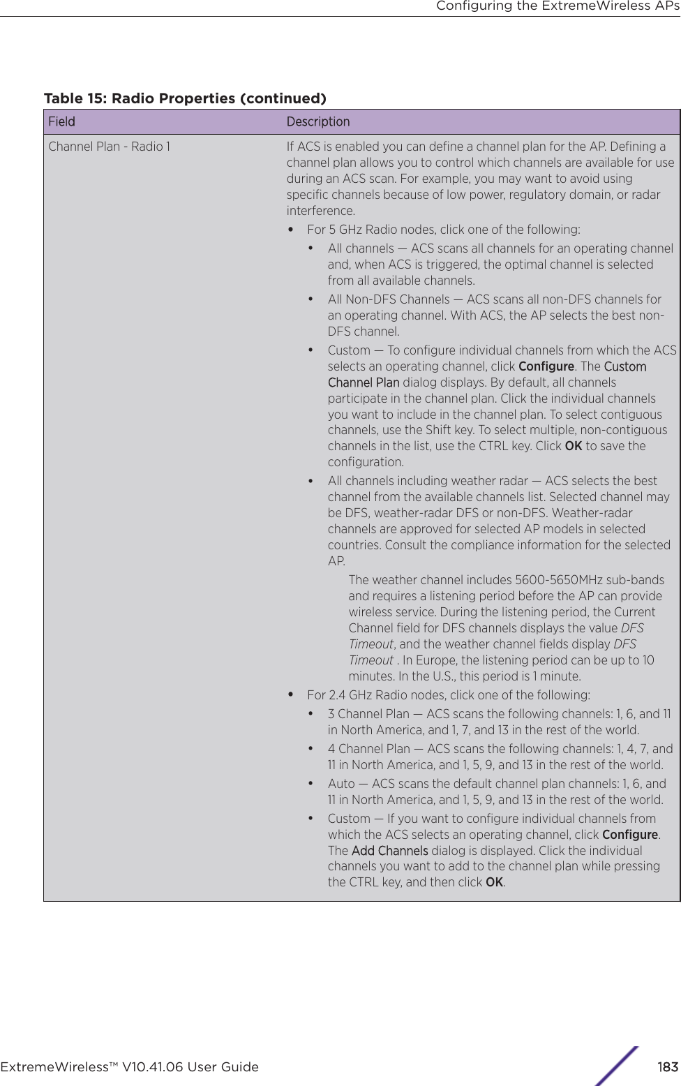
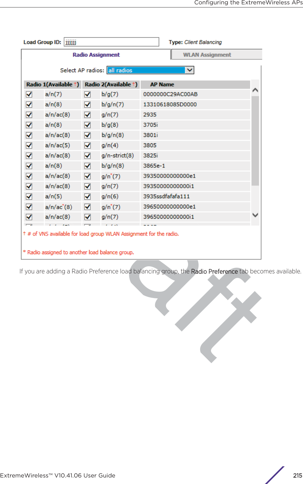
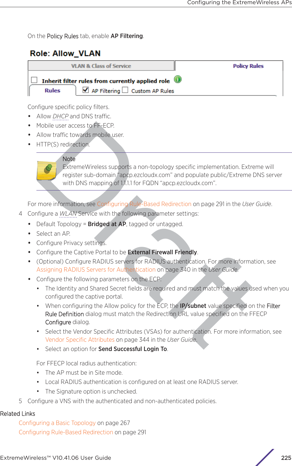
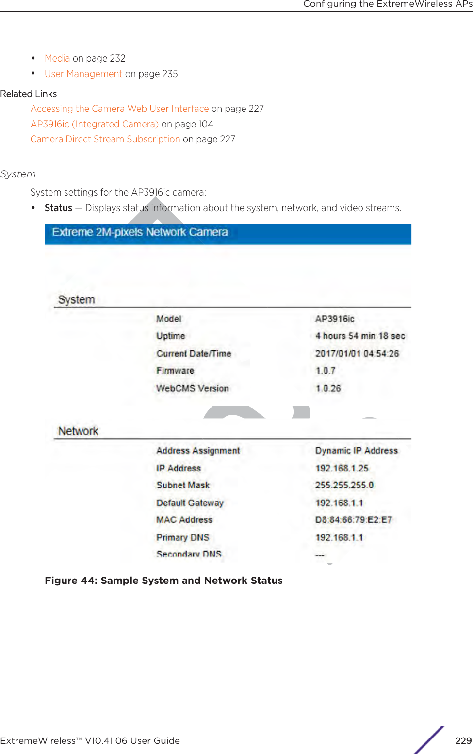
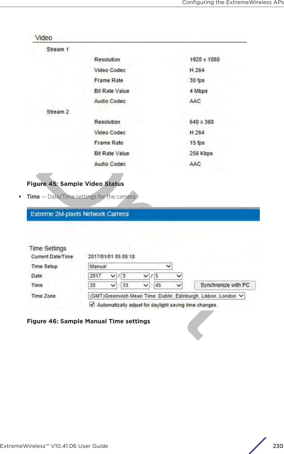
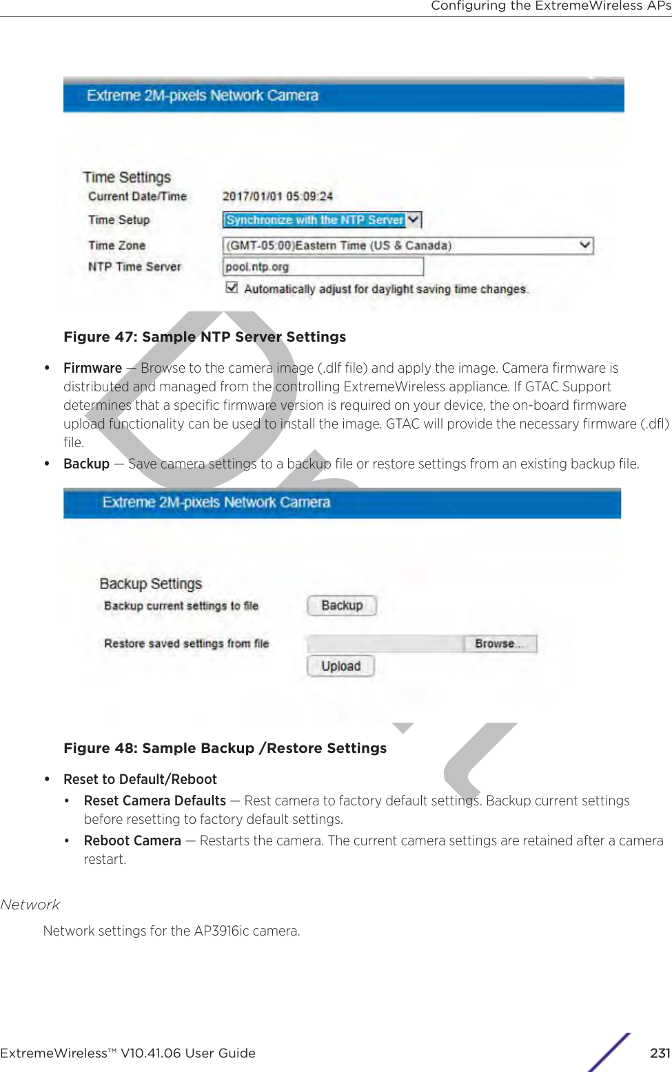
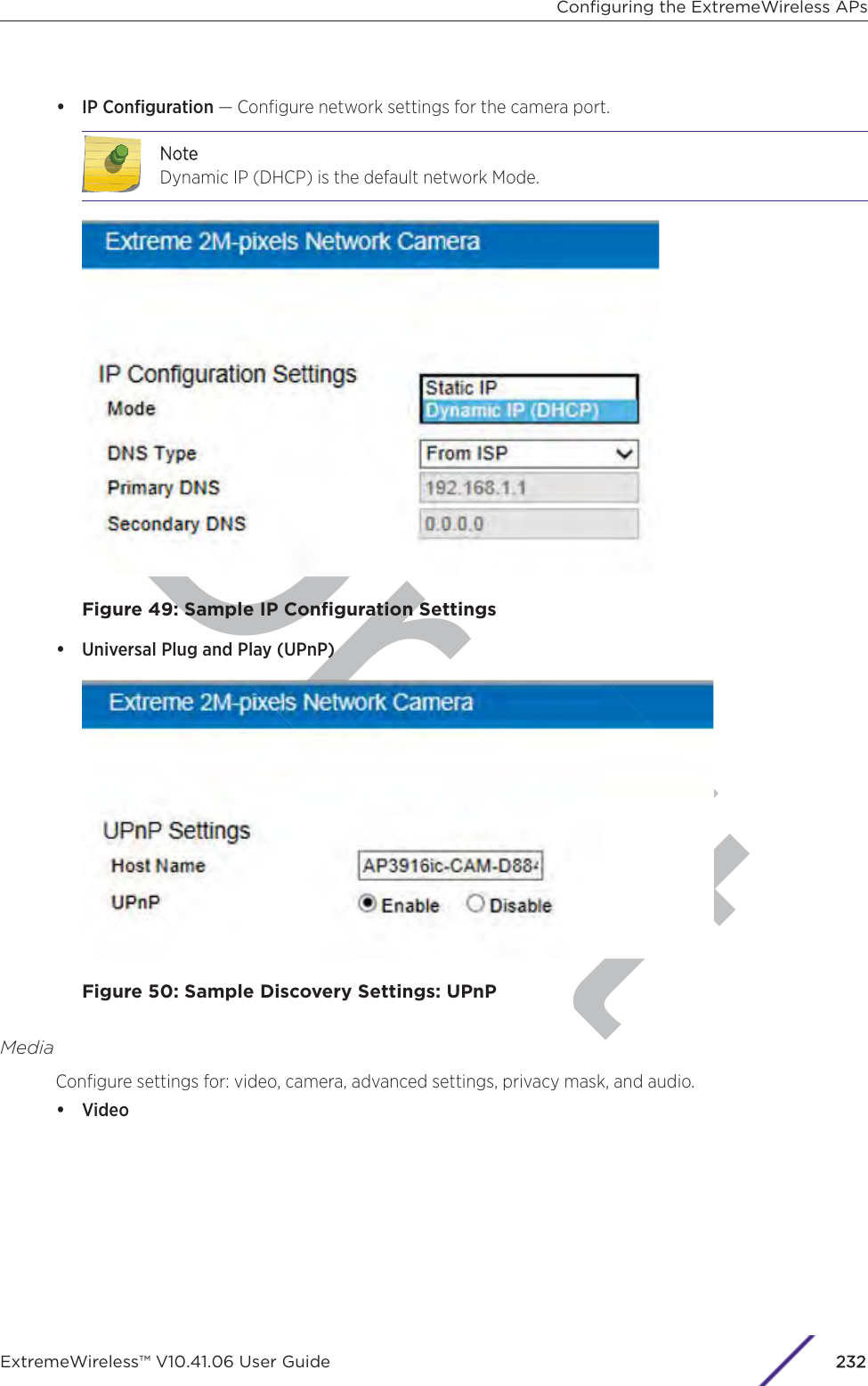
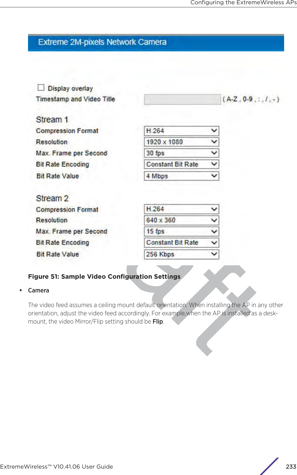
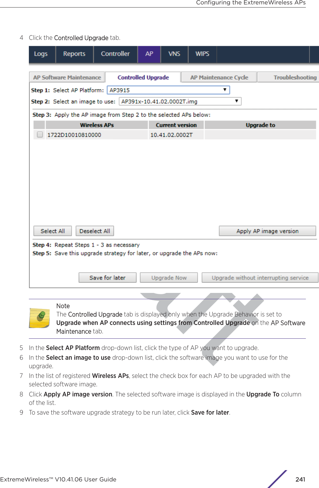
![Draft1 If configuring Rule-based Redirection, verify that Rule-based Redirection is enabled. Go to VNS >Global > Filtering Mode and select Enable Rule-Based Redirection.Rule-Based Redirection is enabled by default for new installations of ExtremeWireless v10.11 andlater. When upgrading from an earlier version of ExtremeWireless, this option is cleared by default.You must enable Rule-Based Redirection from the FFiltering Mode screen.NoteThe option to disable Rule-based Redirection is available for backward capability only.Rule-based Redirection relies on policy rules that are defined for HTTP(S) redirection. Non-Rule-based Redirection automatically redirects an un-authenticated client to ECP when a deny actionoccurs on HTTP(S) trac.NoteYou cannot configure Captive Portal Redirection using IPv6 classifiers. While you can httpto IPv6 websites, you cannot apply Captive Portal redirection to http [s] over IPv6 .2 Create a basic topology where the topology mode is Bridge Trac Locally at AP. The topology canbe tagged or untagged. For more information, see Configuring a Basic Topology on page 267 in theUser Guide.If using RADIUS authentication, FF-ECP on the AP can work with both local and central RADIUSauthentication.3 Create a role and define specific policy rules.The role must be configured with the following parameters:From the VVLAN & Class of Service tab, select a default Access Control value for the role.Select from one of the following:•None - No role defined•No change - Default setting•Allow - Packets contained to role's default action's VLAN/topology.•Deny - Any packet not matching a rule in the Role is dropped.•Containment VLAN - Any packet not matching a rule is sent to defined VLAN.For B@AP trac, only the FF ECP is supported as an external captive portal.Configuring the ExtremeWireless APsExtremeWireless™ V10.41.06 User Guide224](https://usermanual.wiki/Extreme-Networks/AP3917E.Extreme-Wireless-V10-41-06-User-Guide-Part-1/User-Guide-3831181-Page-224.png)