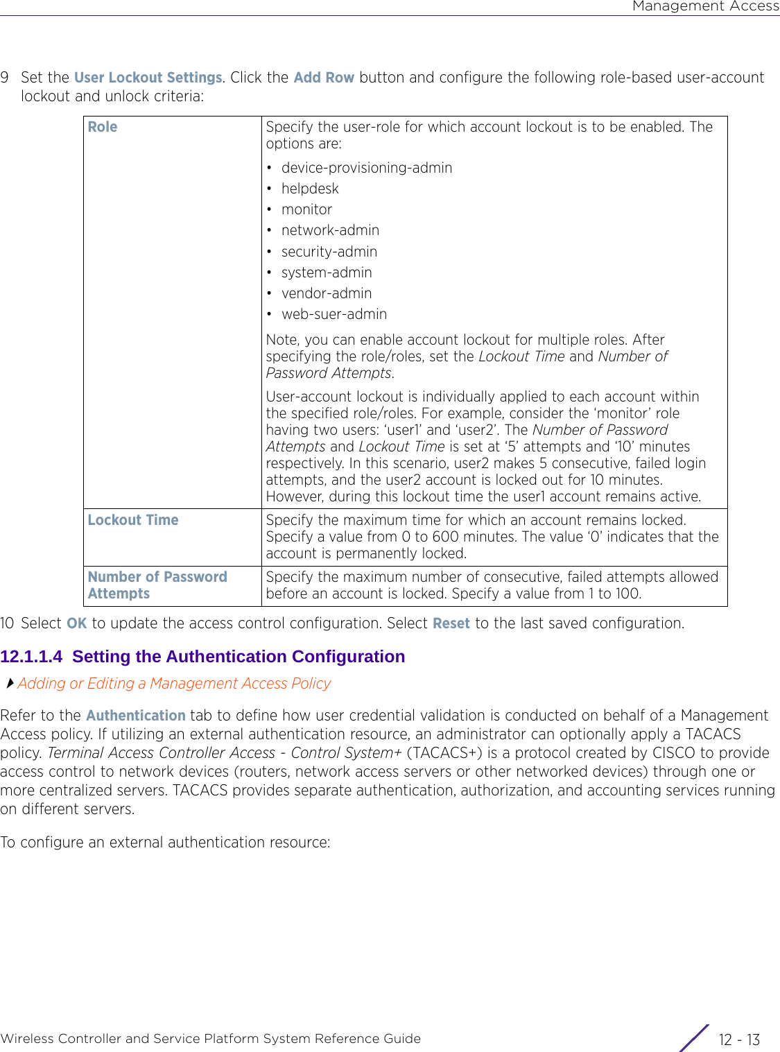
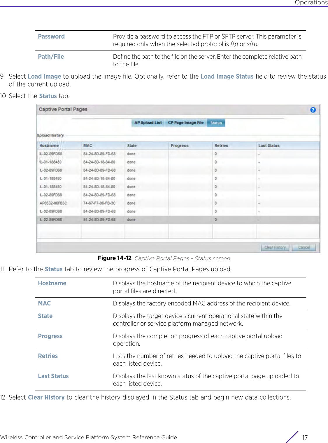
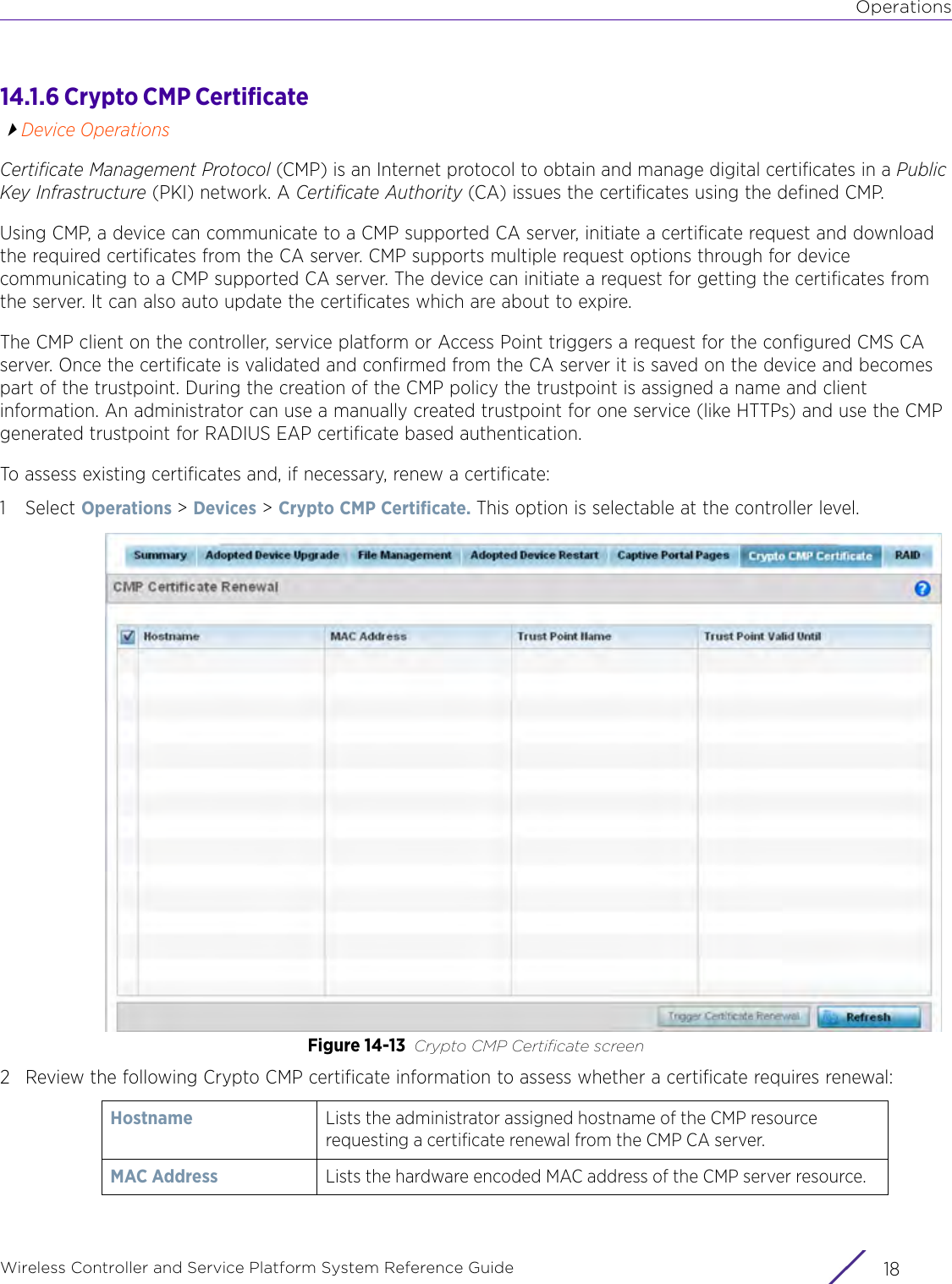
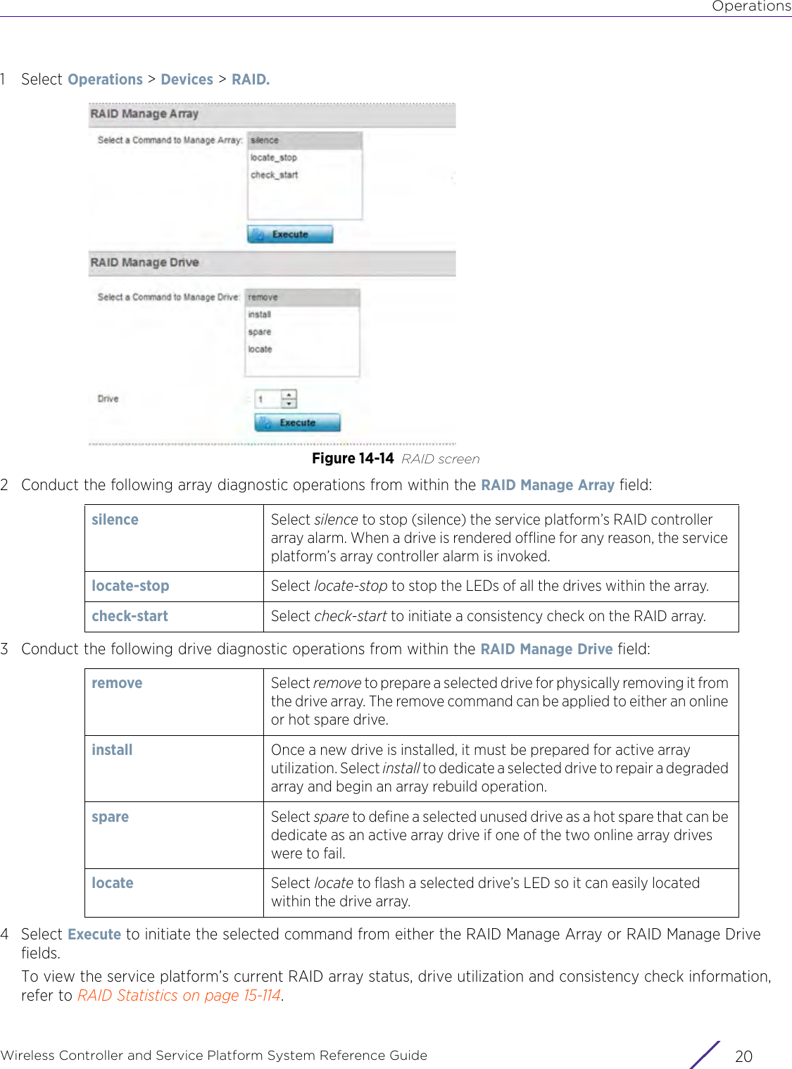
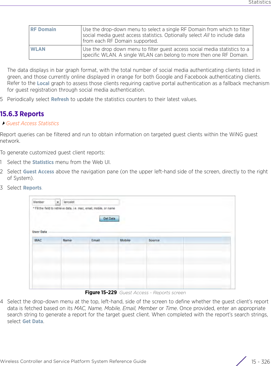
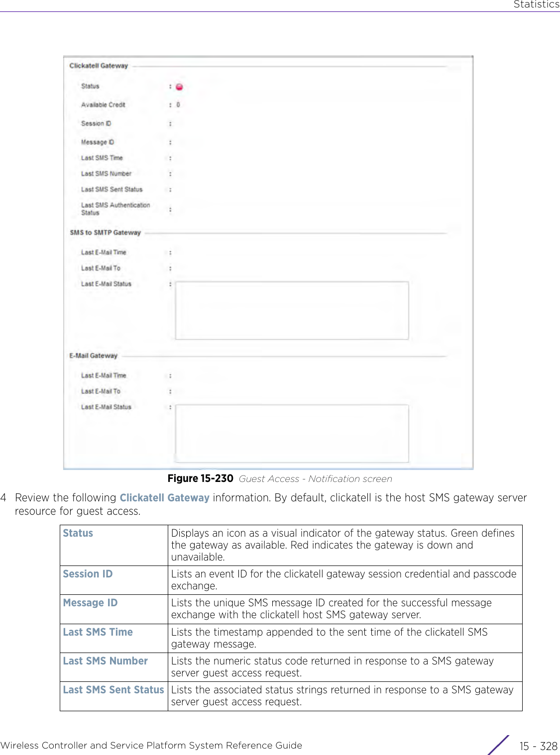
Extreme Networks AP3917E Wireless 802.11 a/ac+b/g/n Access Point User Manual WiNG 5 9 1 System Reference Guide Part 3
Extreme Networks, Inc. Wireless 802.11 a/ac+b/g/n Access Point WiNG 5 9 1 System Reference Guide Part 3
Contents
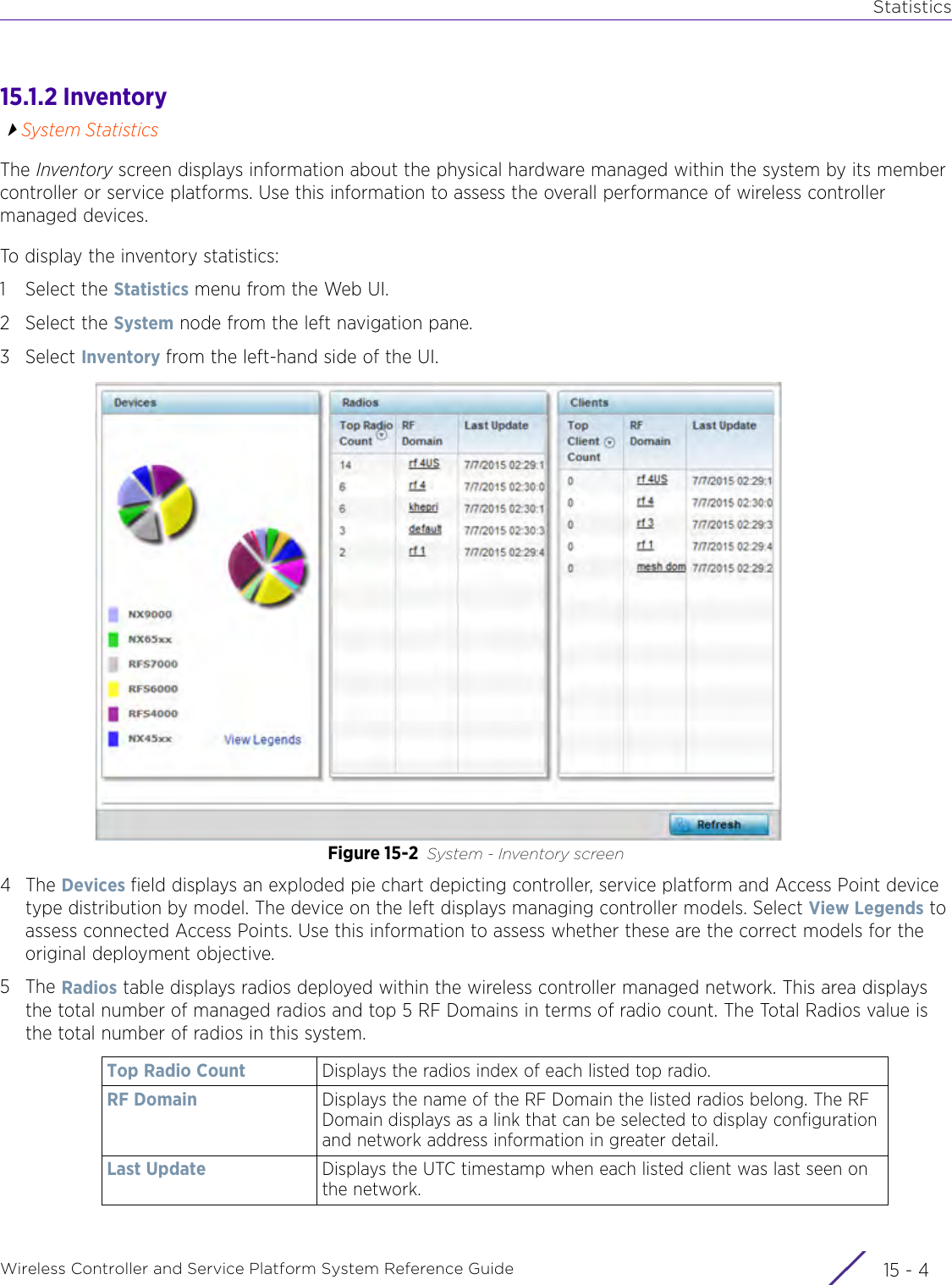
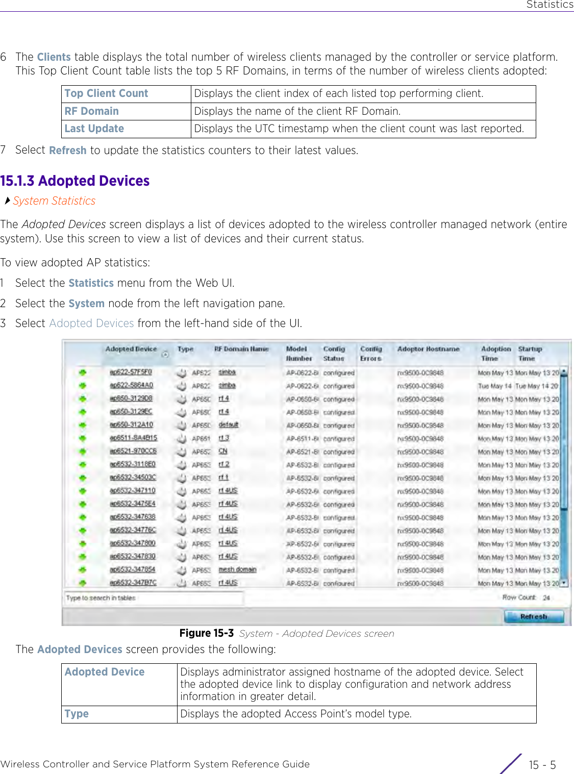
- 1. User Manual-AP3917e
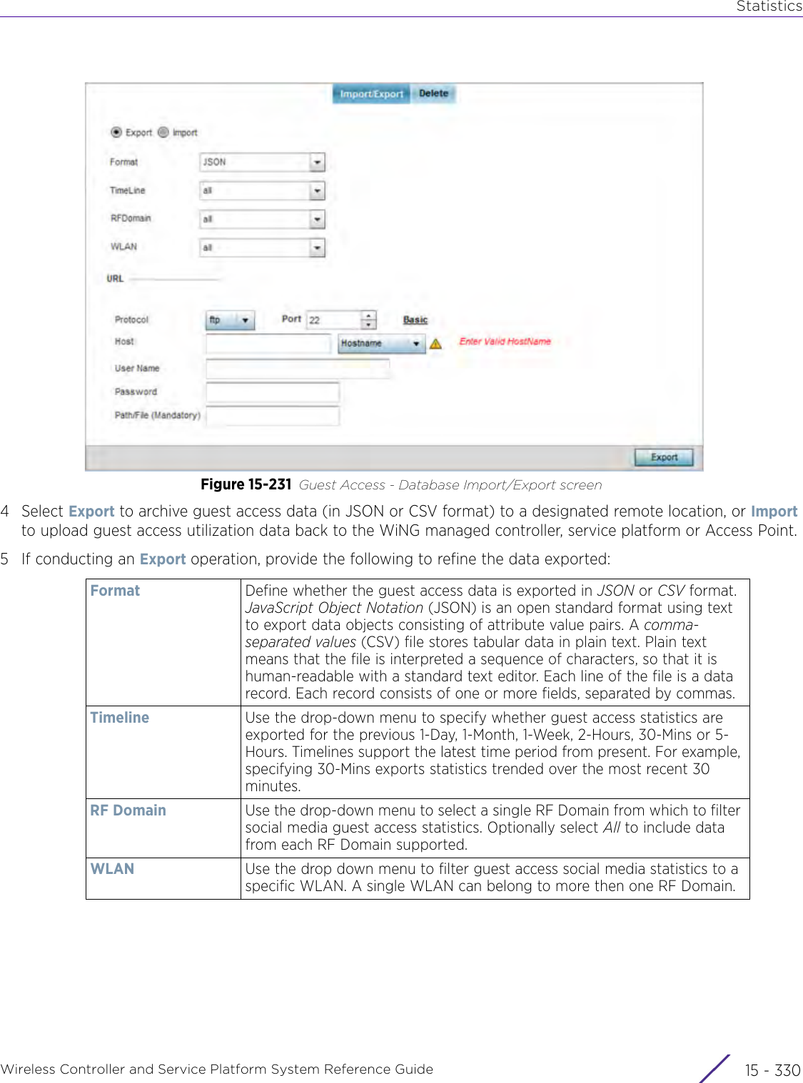
- 2. User Manual-AP7662
- 3. User Manual-AP3917e R1
- 4. User Manual-AP7662 R1
- 5. WiNG 5.9.1 System Reference Guide Part 1
- 6. WiNG 5.9.1 System Reference Guide Part 2
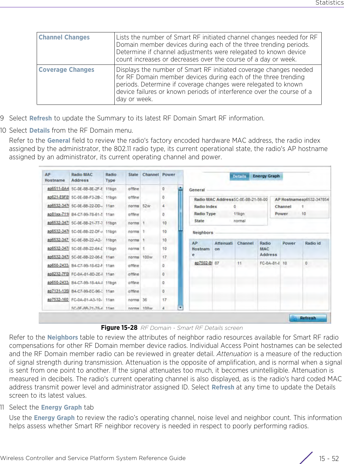
- 7. WiNG 5.9.1 System Reference Guide Part 3
- 8. WiNG 5.9.1 System Reference Guide Part 4
- 9. WiNG 5.9.1 CLI Reference Guide Part 1
- 10. WiNG 5.9.1 CLI Reference Guide Part 2
- 11. Extreme Wireless V10.41.06 User Guide Part 1
- 12. AP3917 User Manual
- 13. AP7662 User Manual
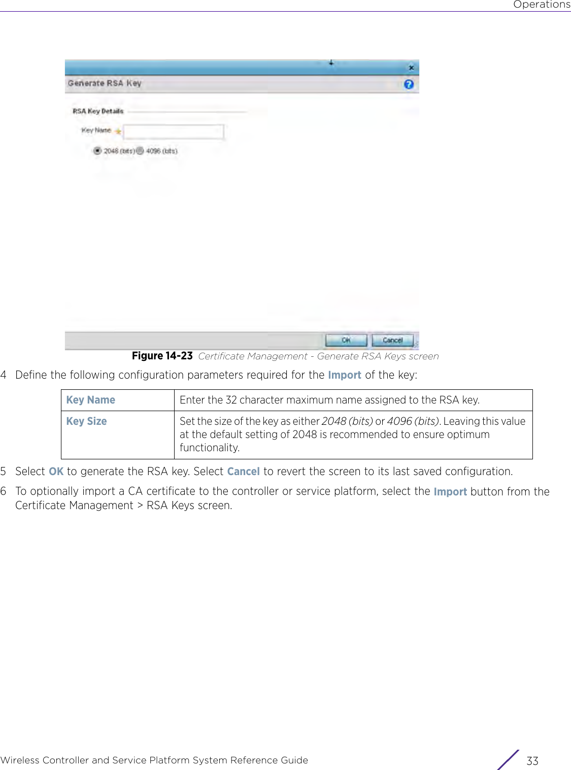
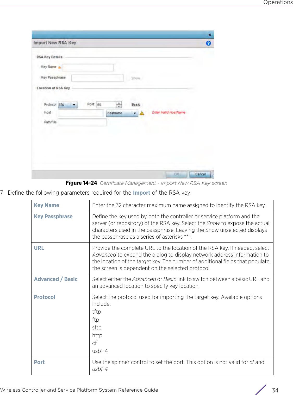
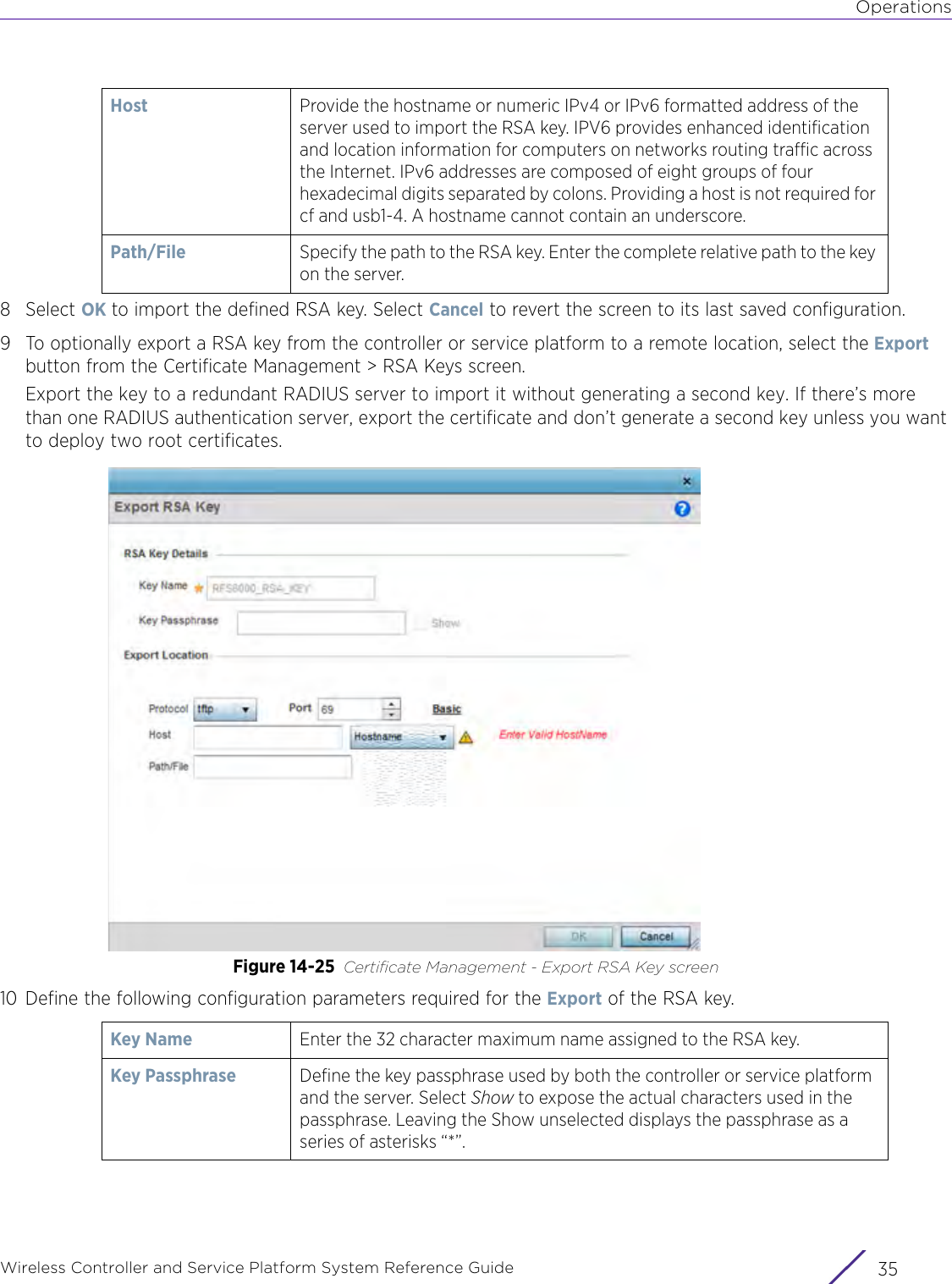
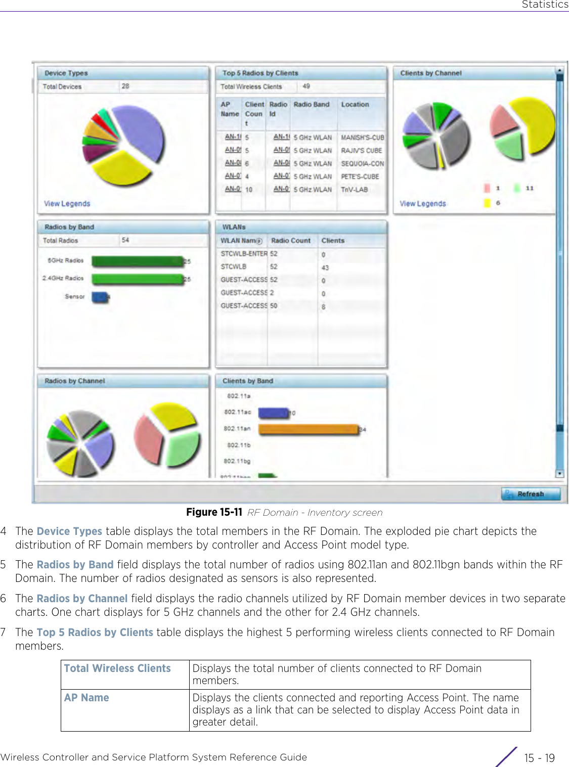
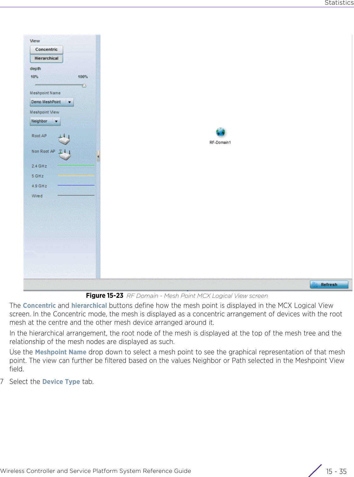
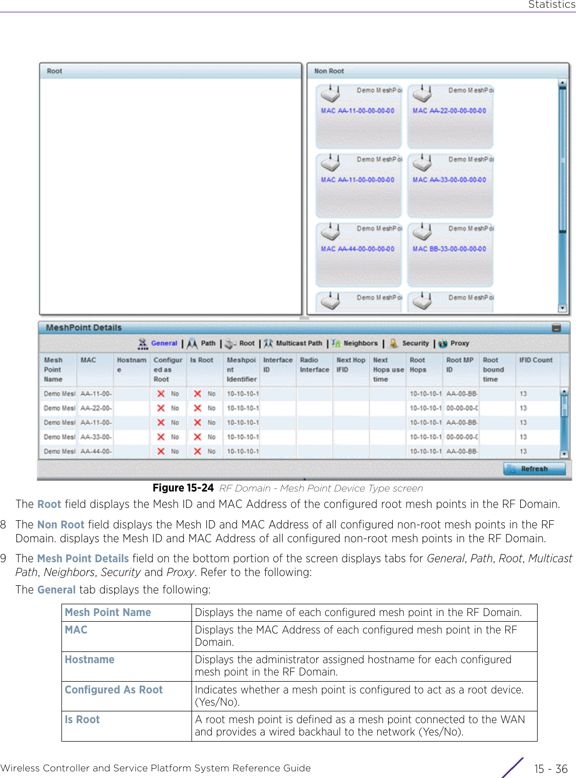
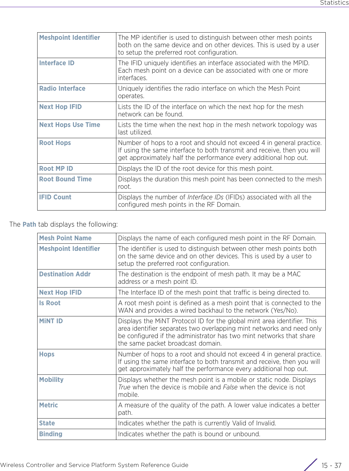
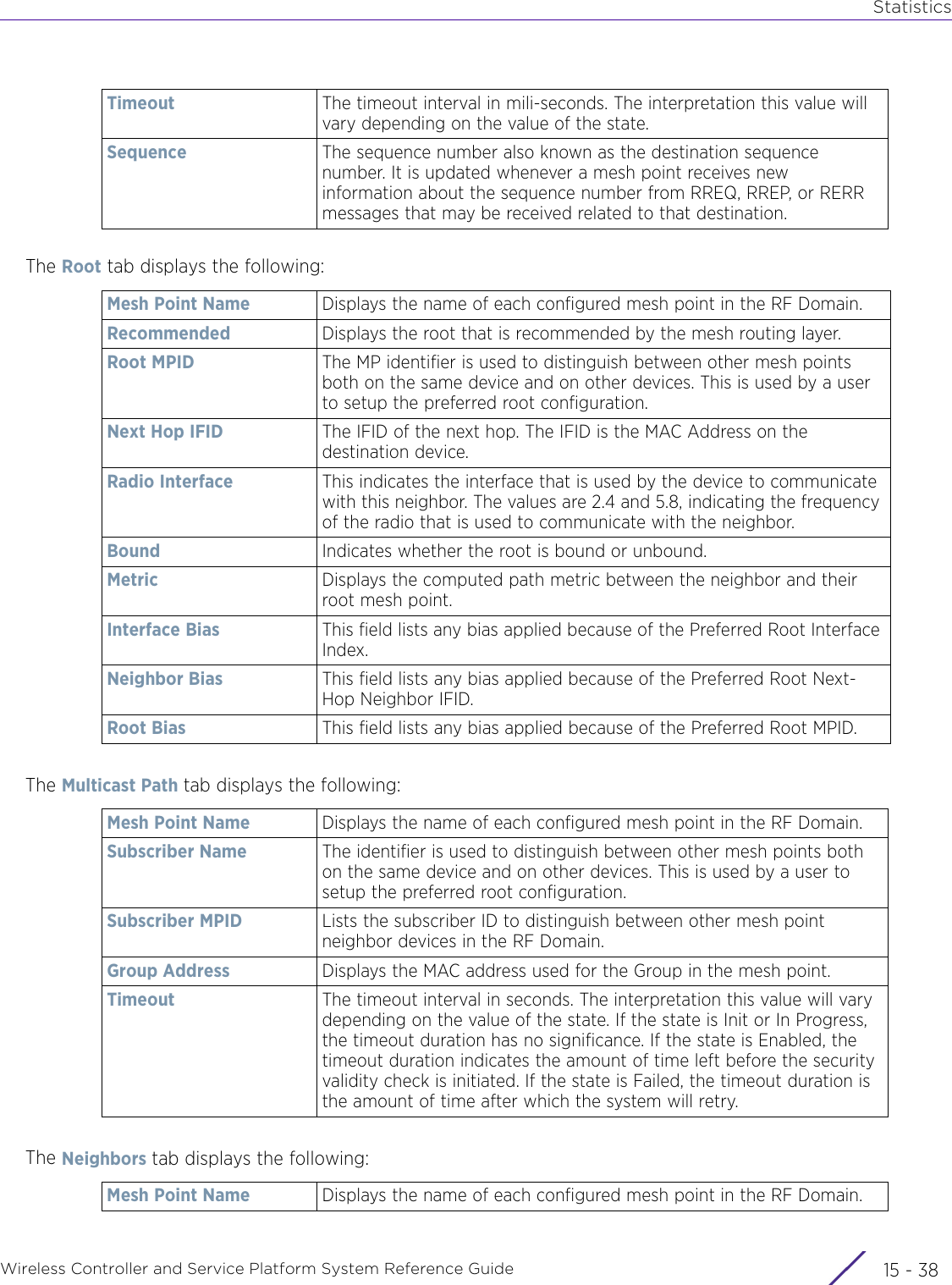
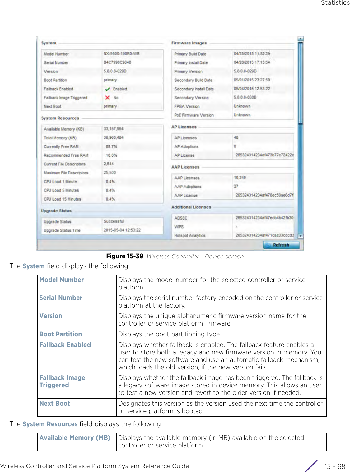
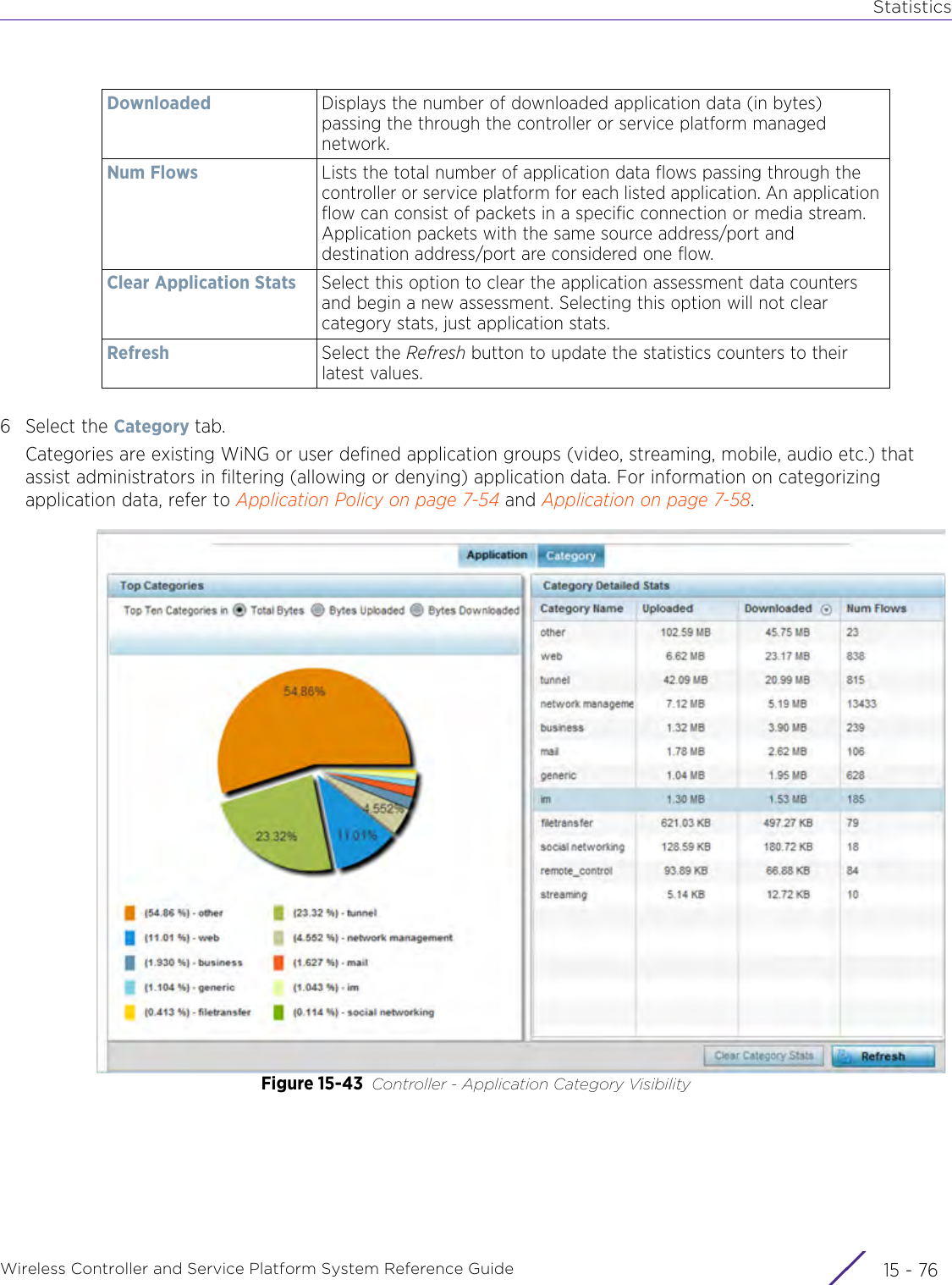
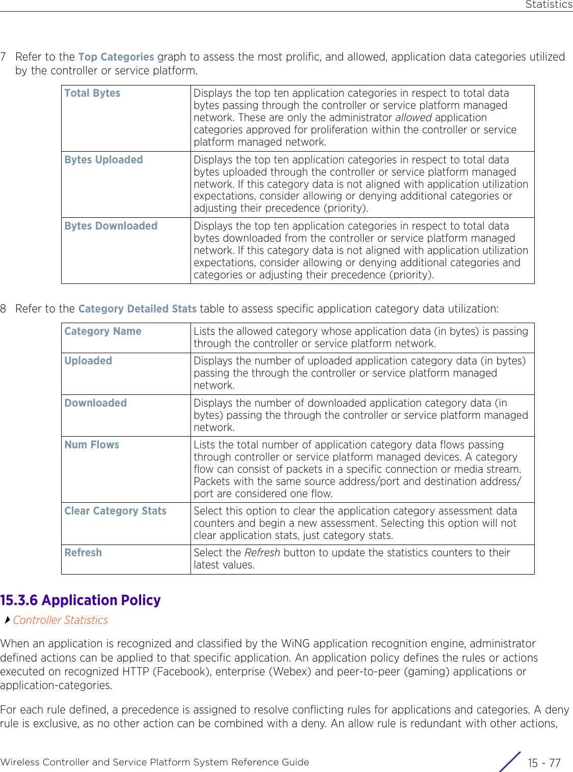
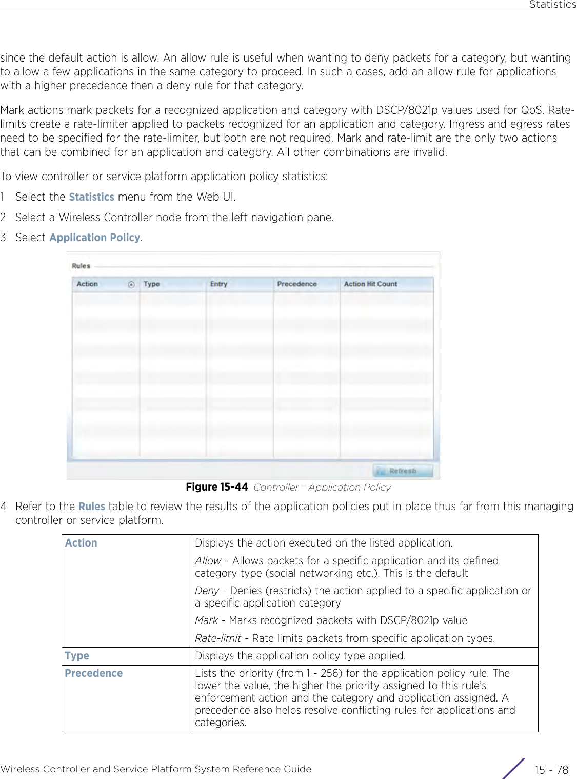
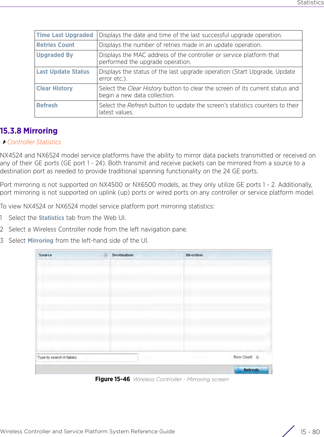
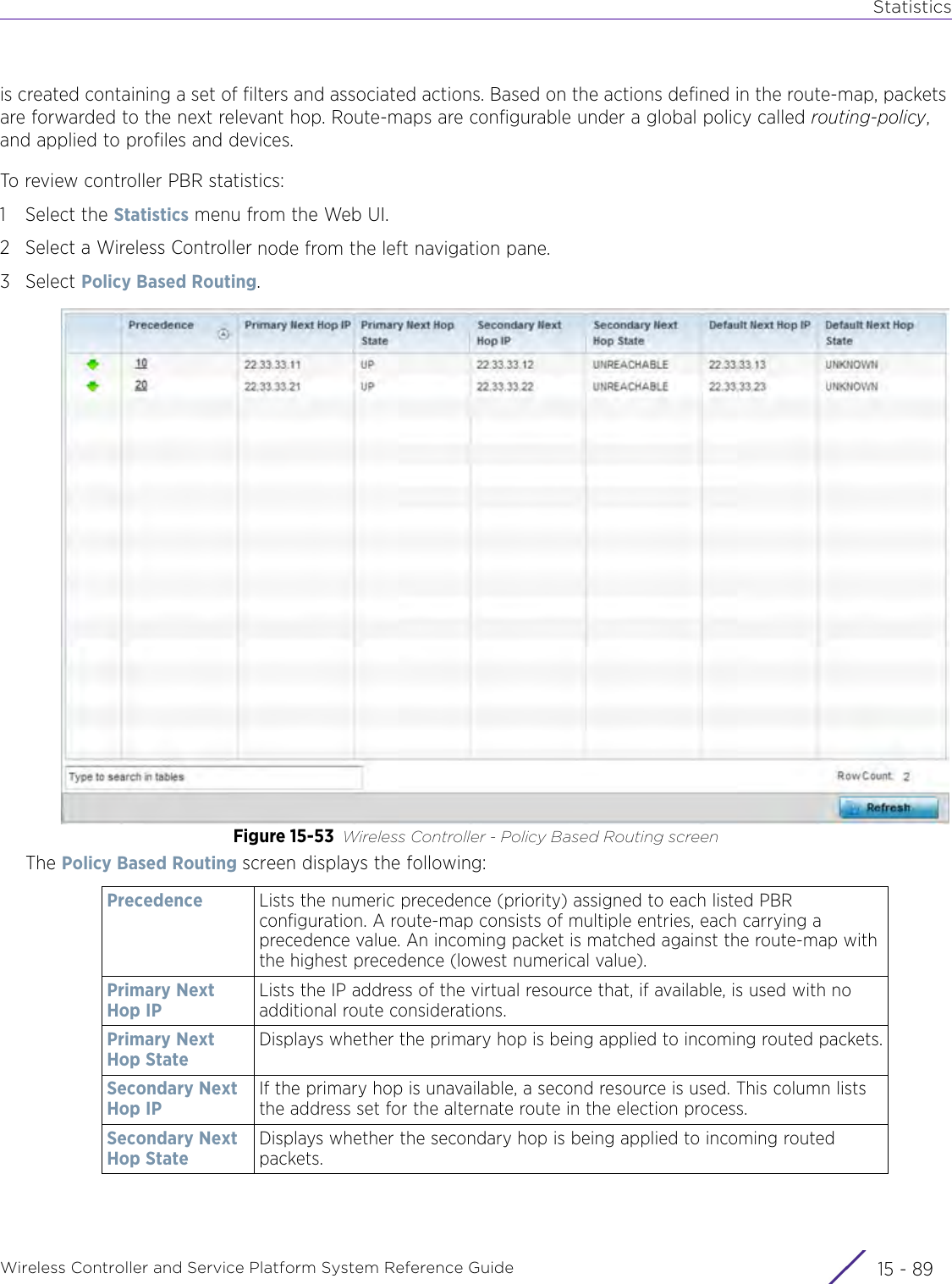
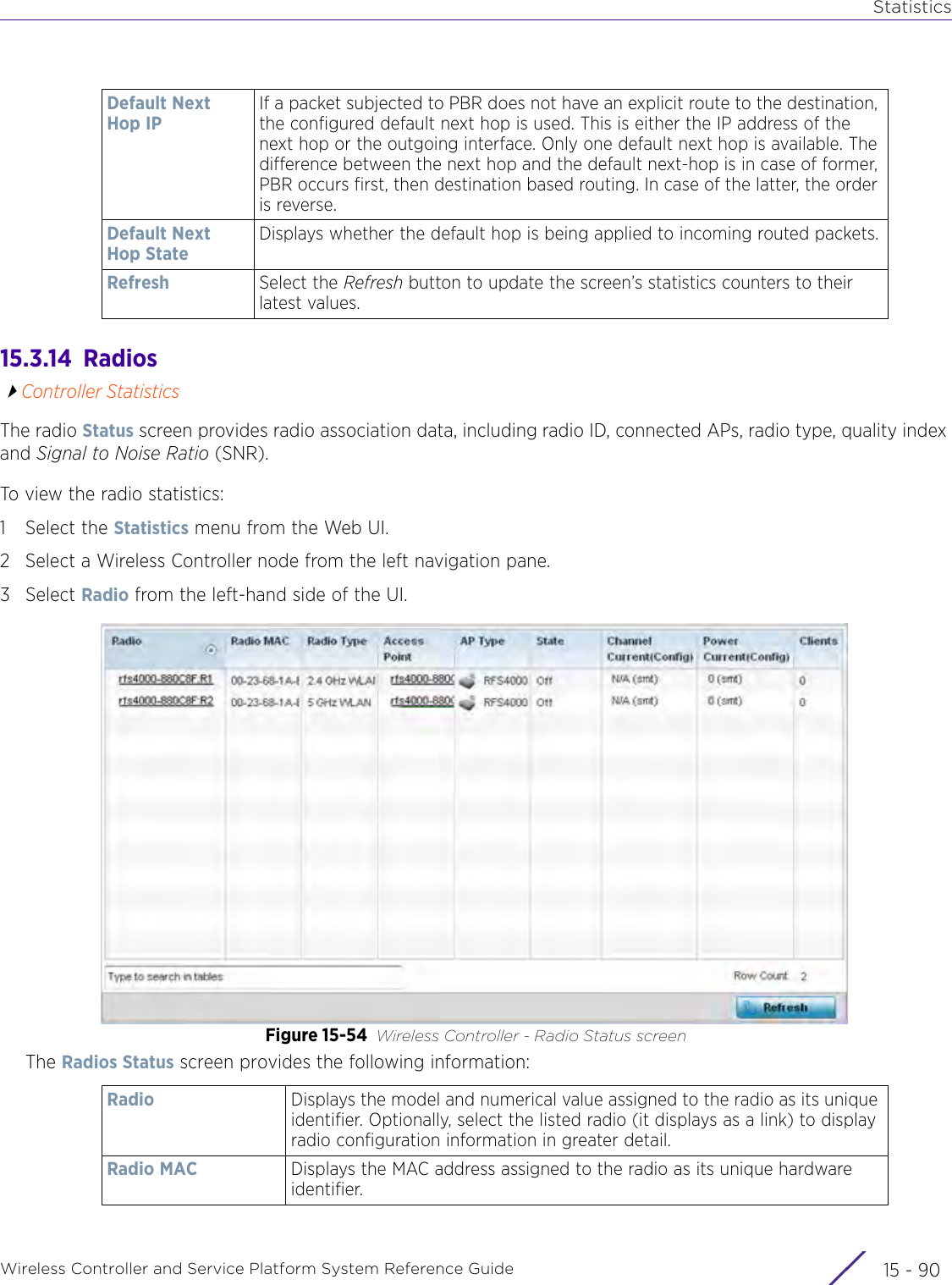
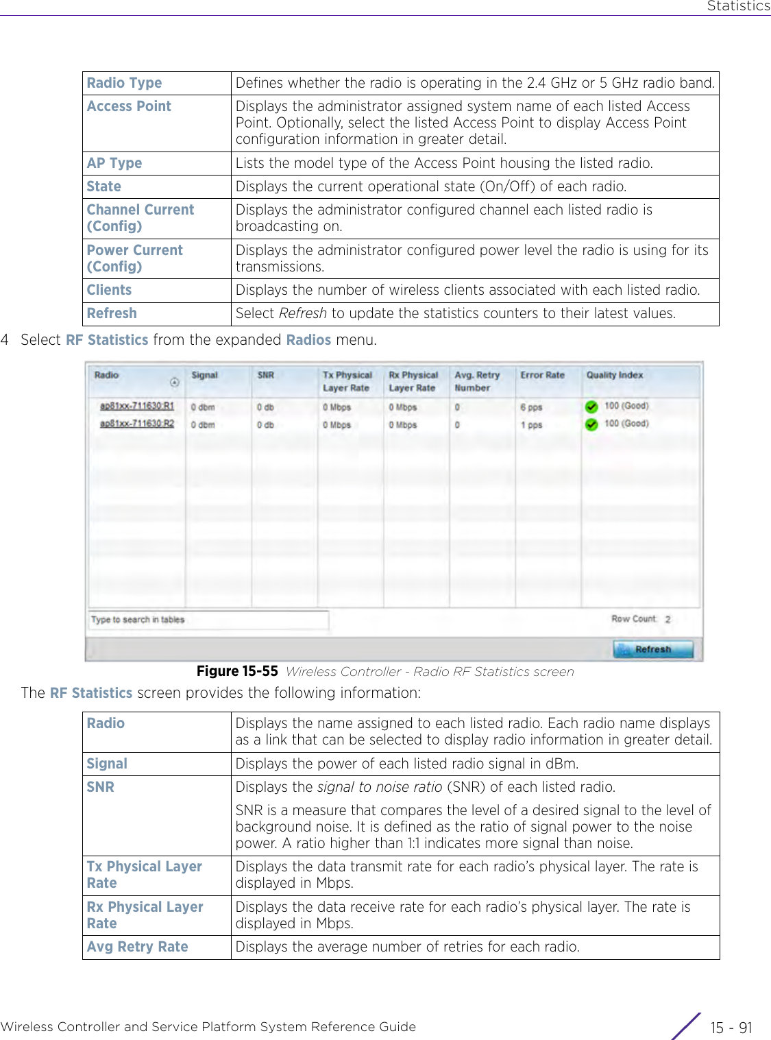
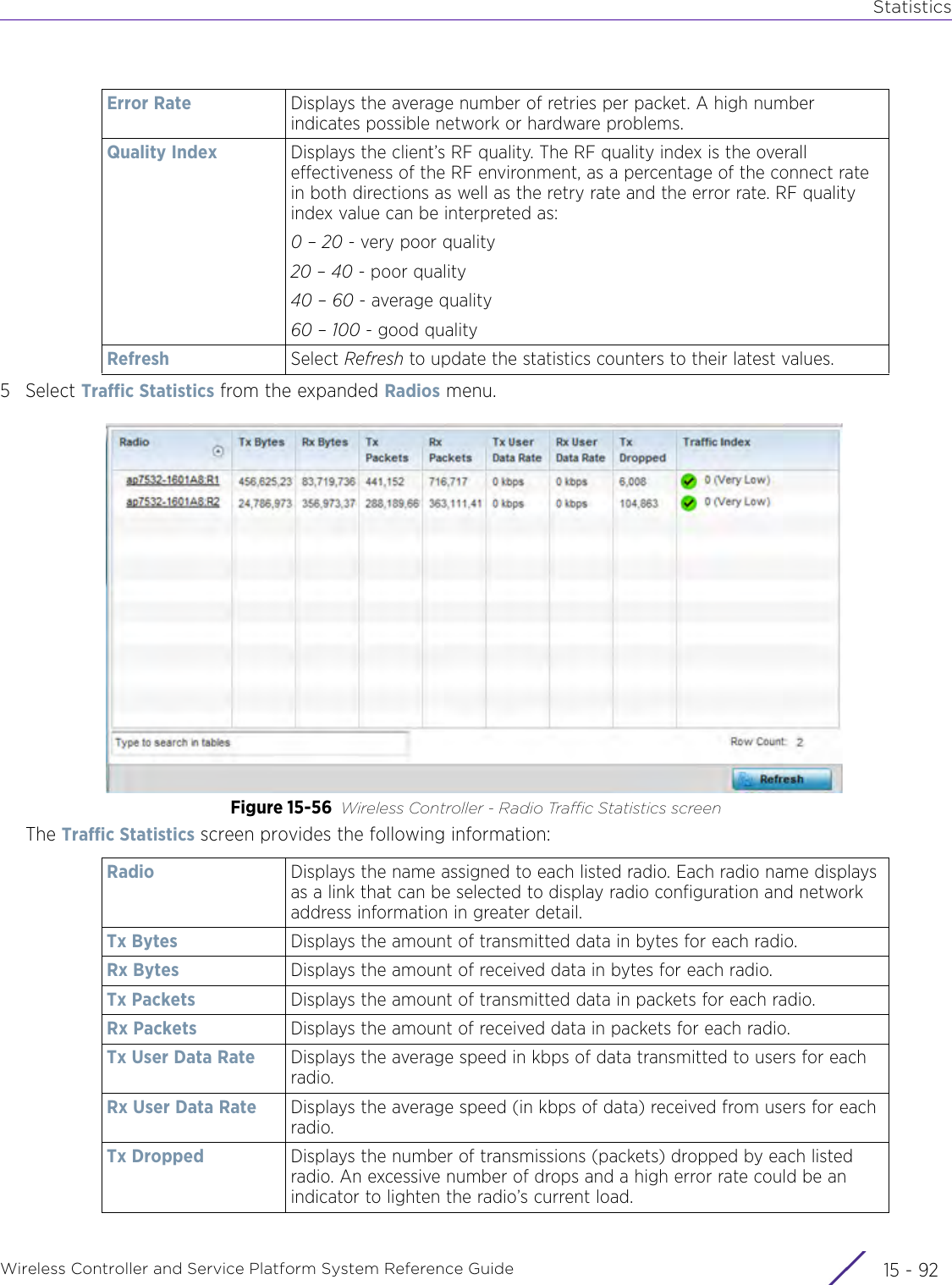
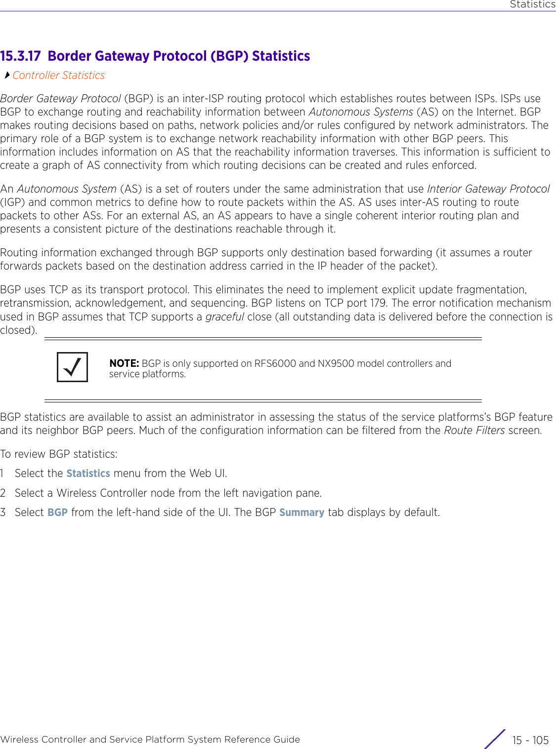
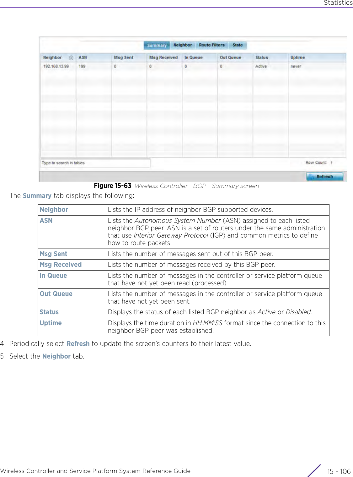
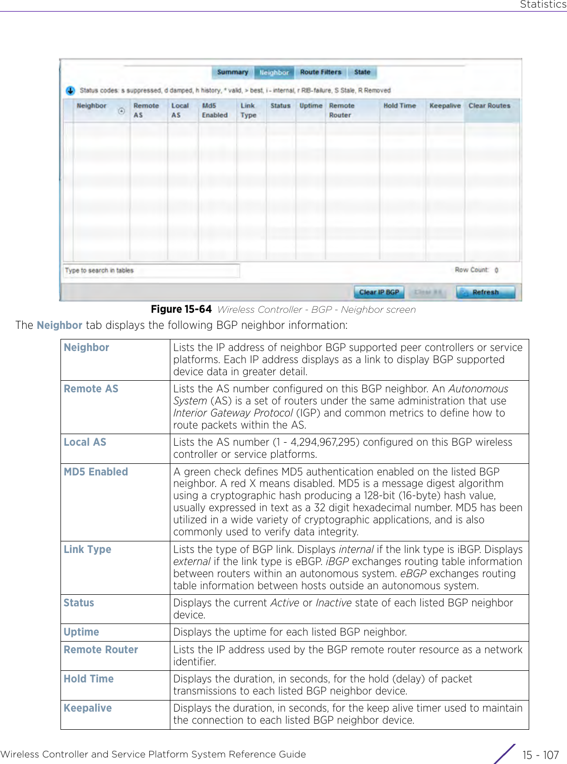
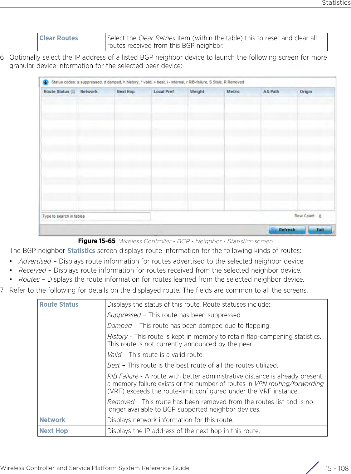
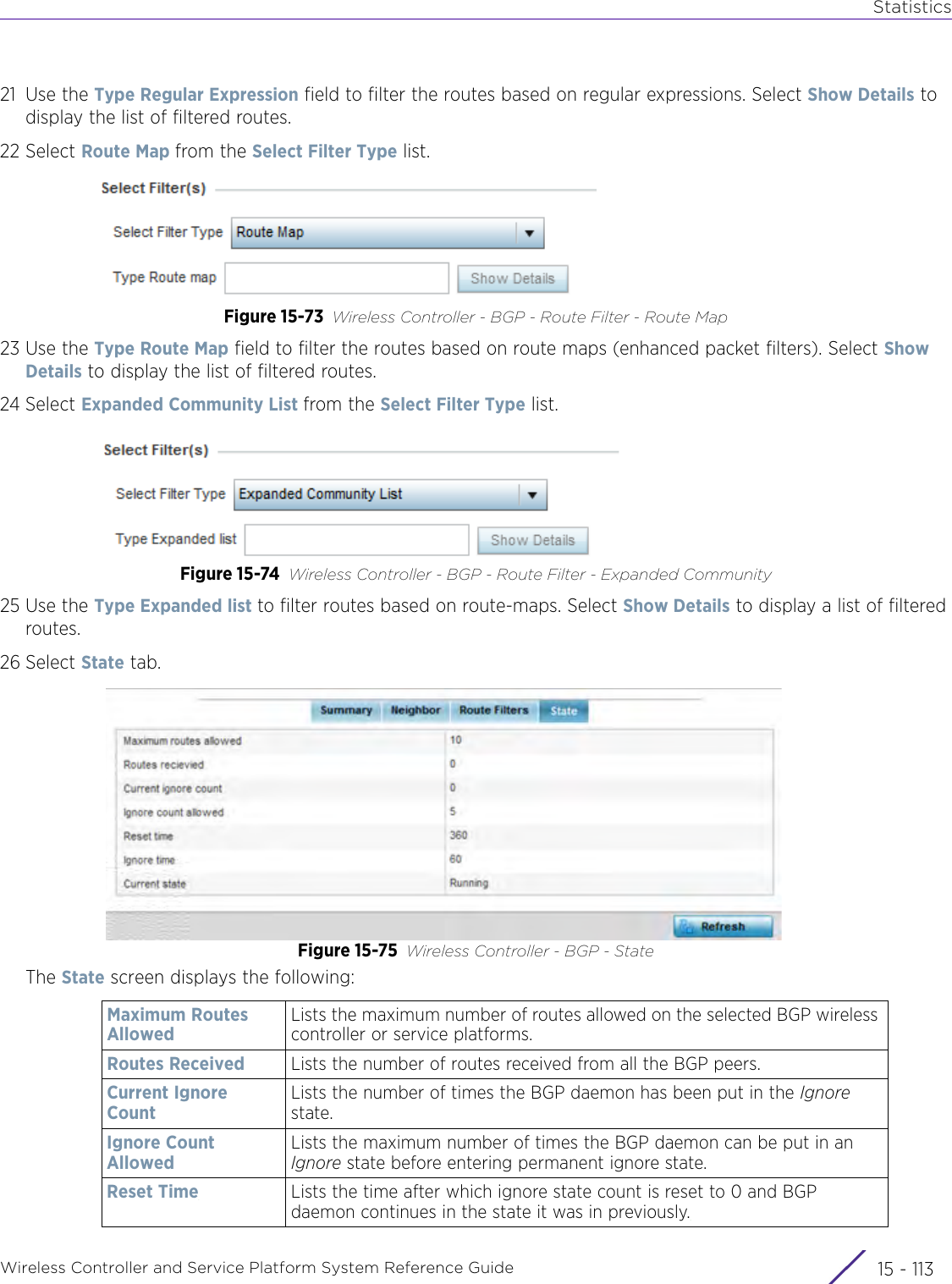
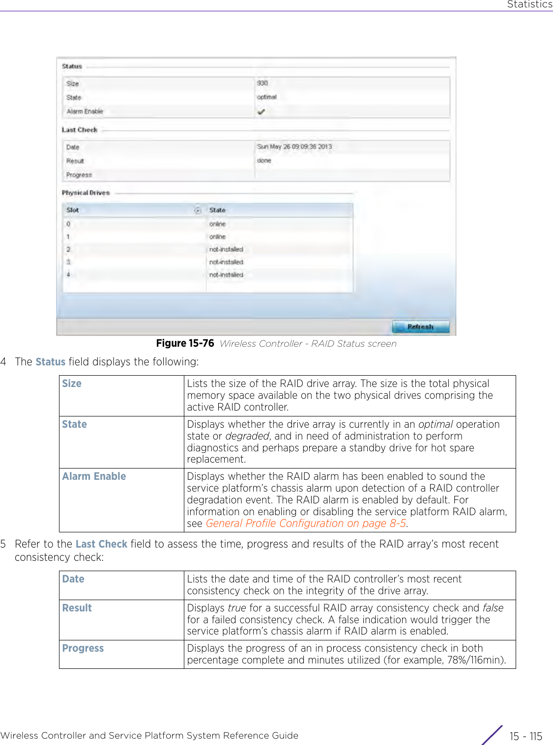
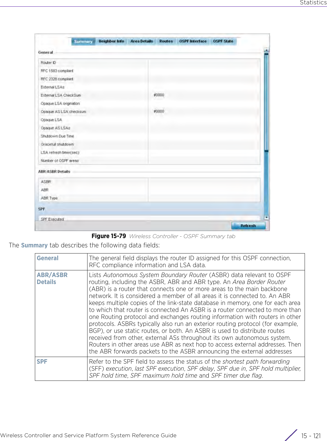
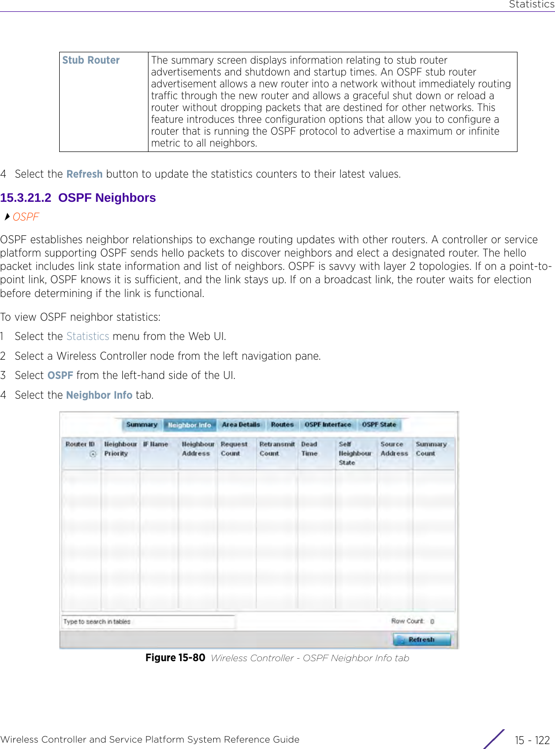
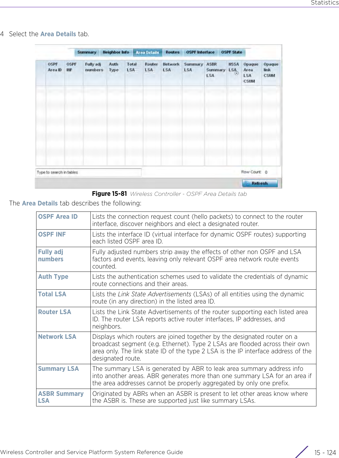
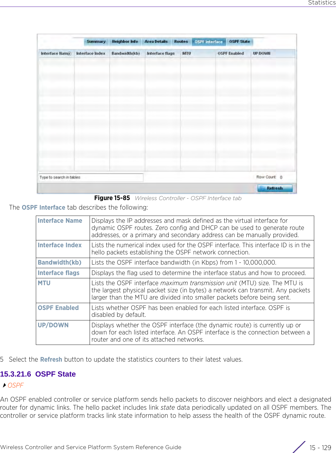
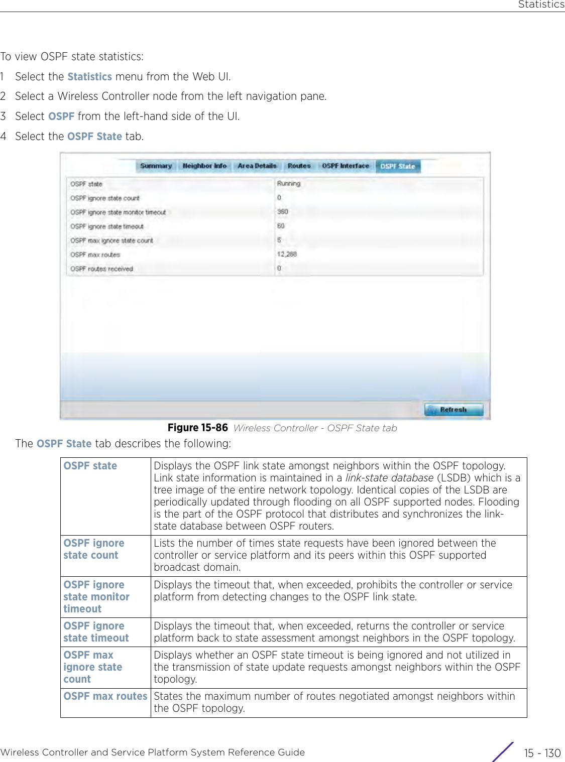
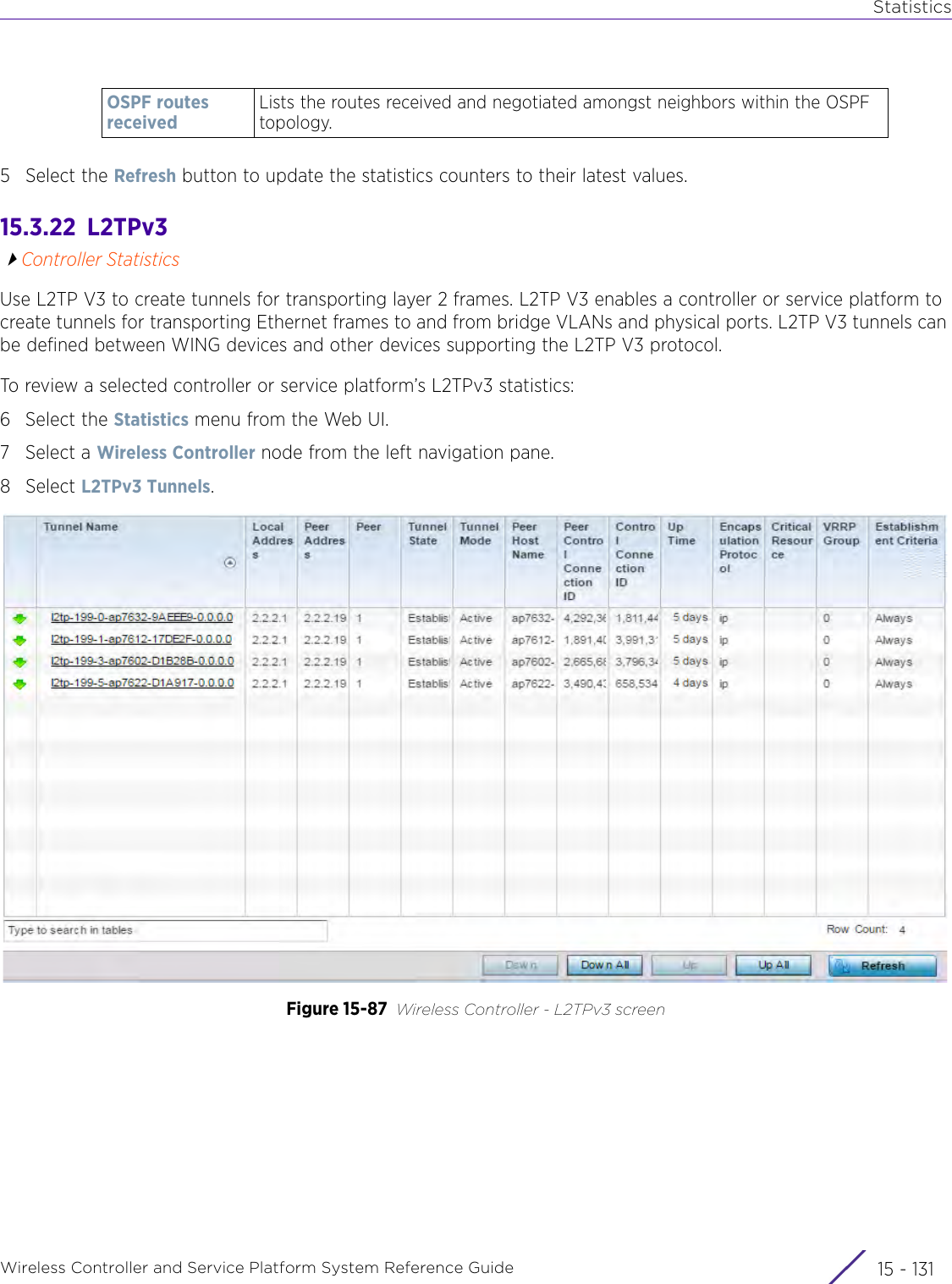
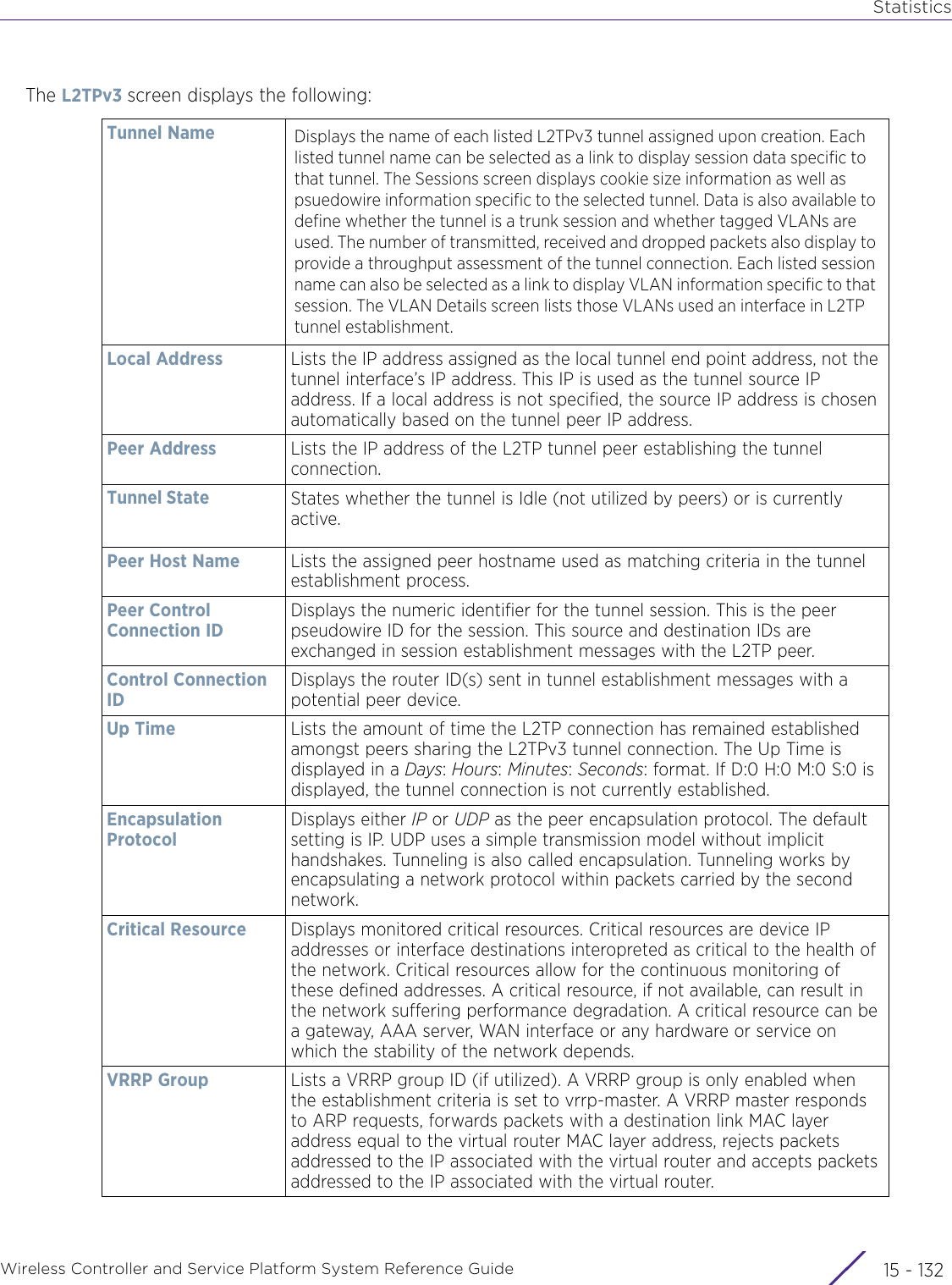
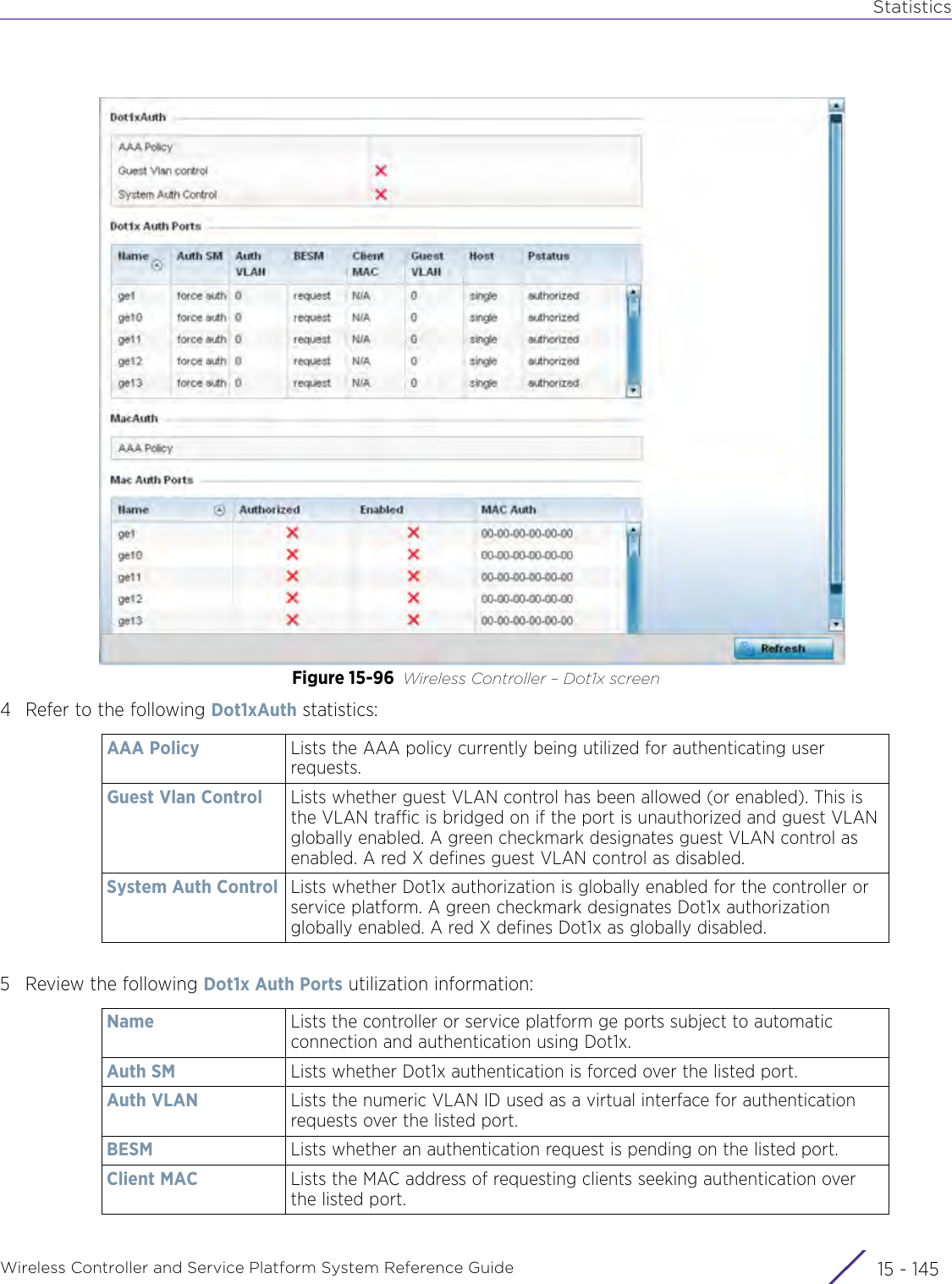
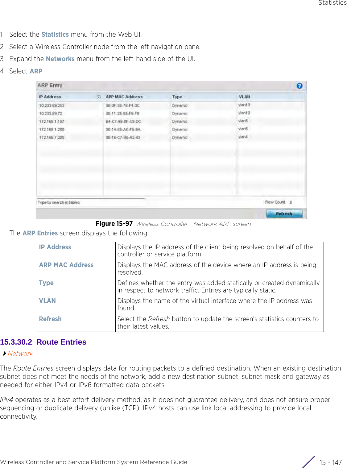
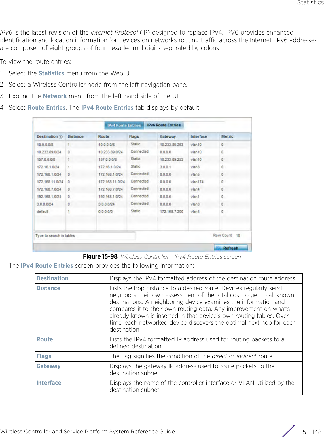
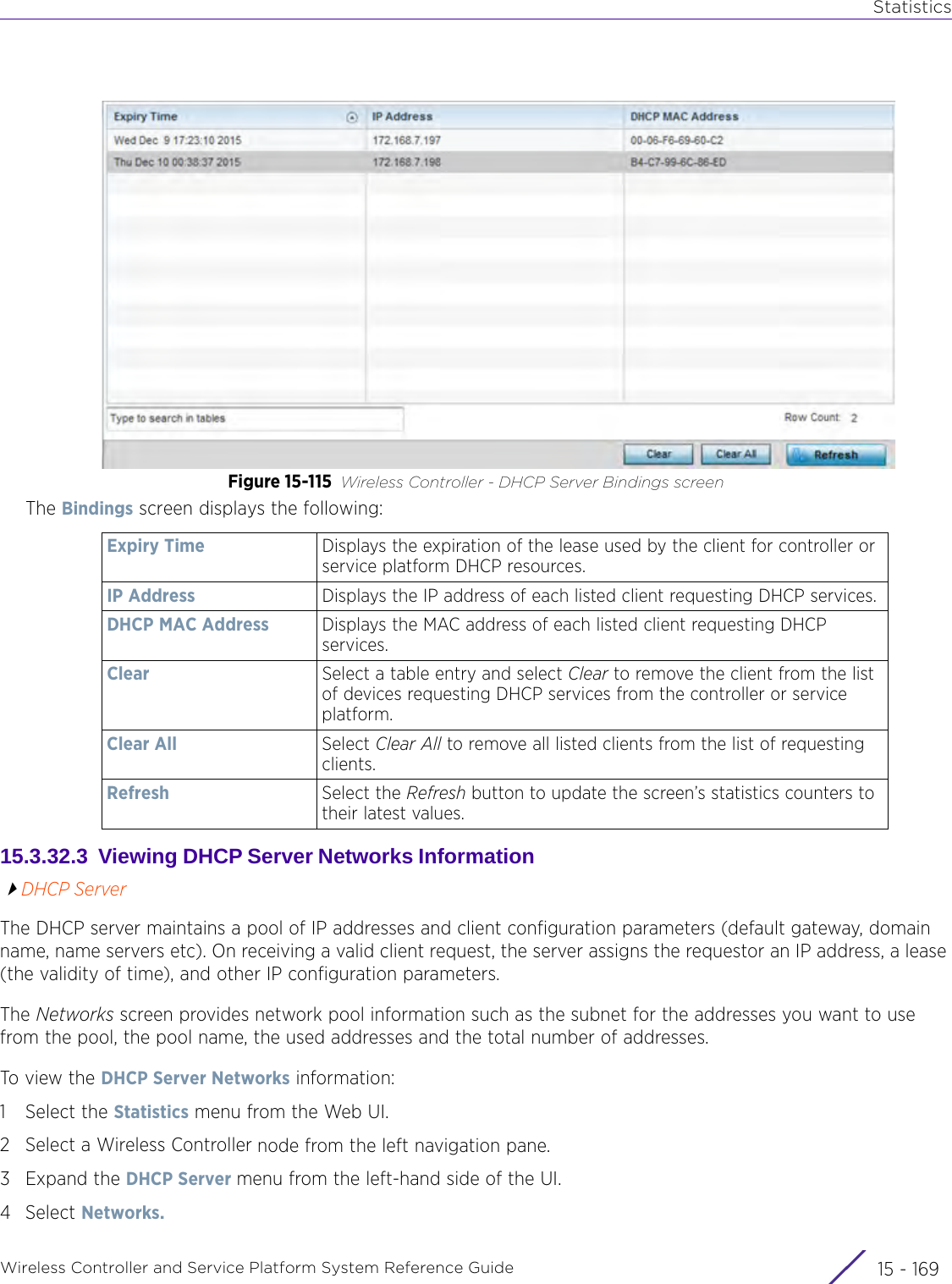
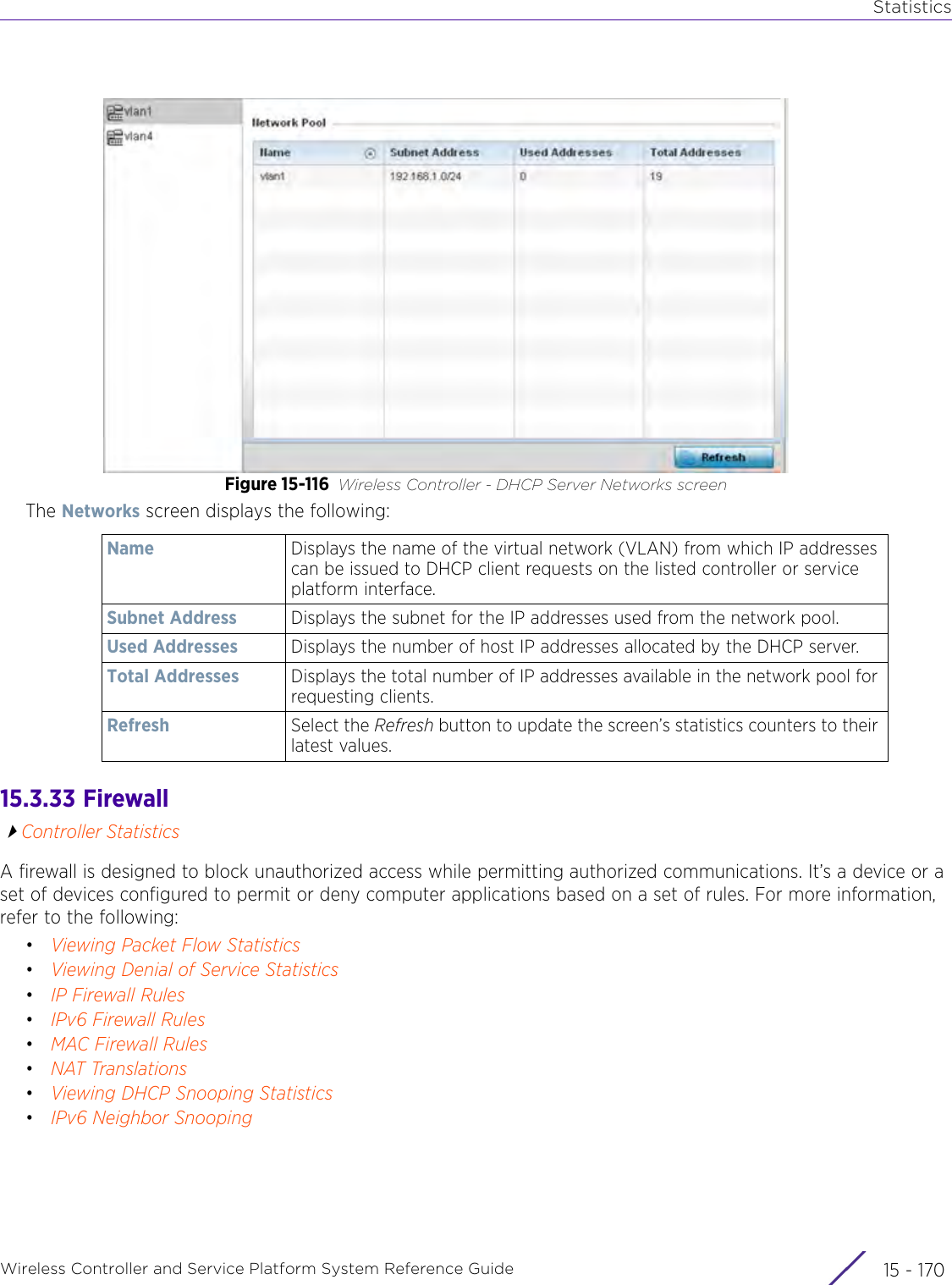
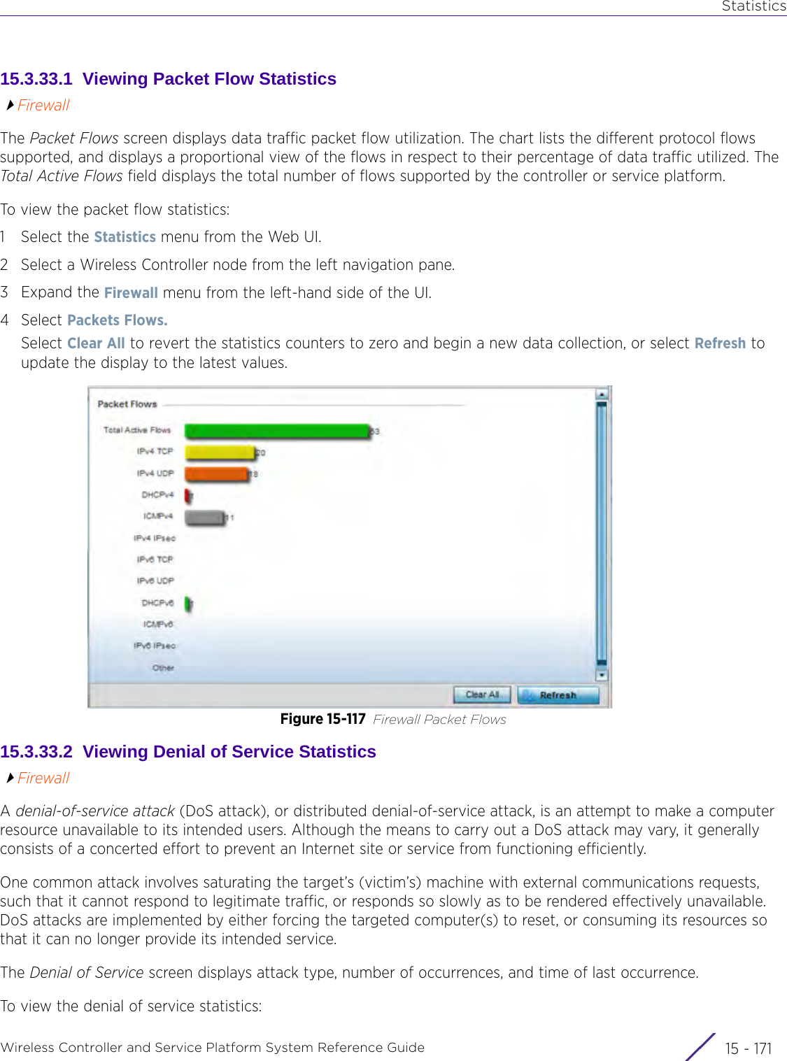
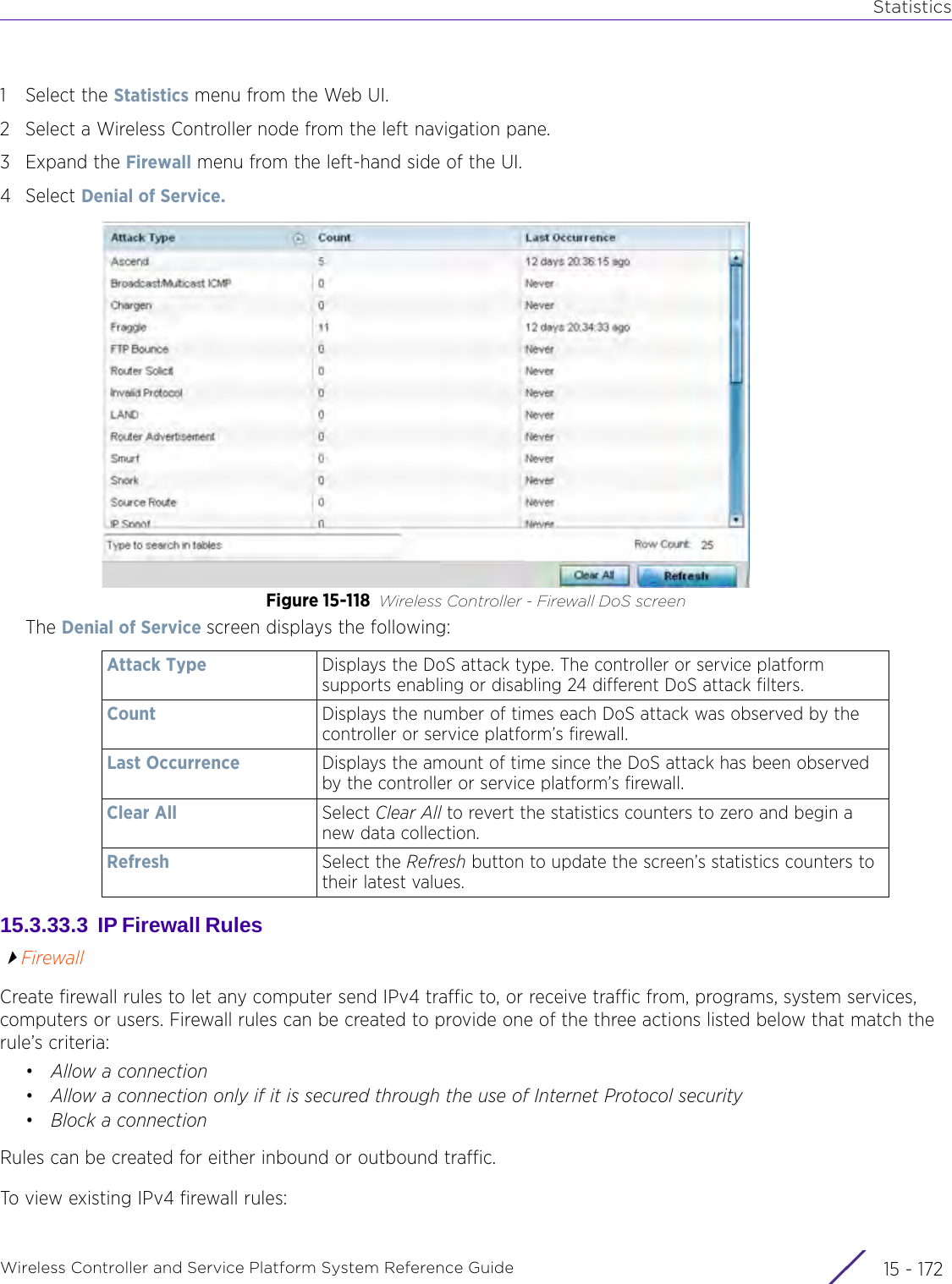
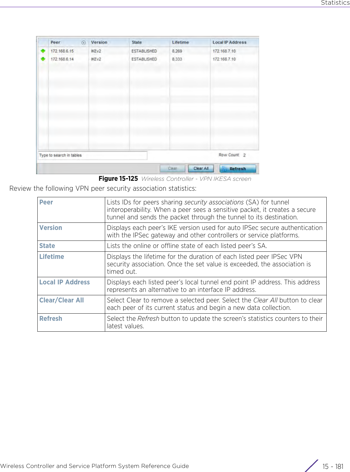
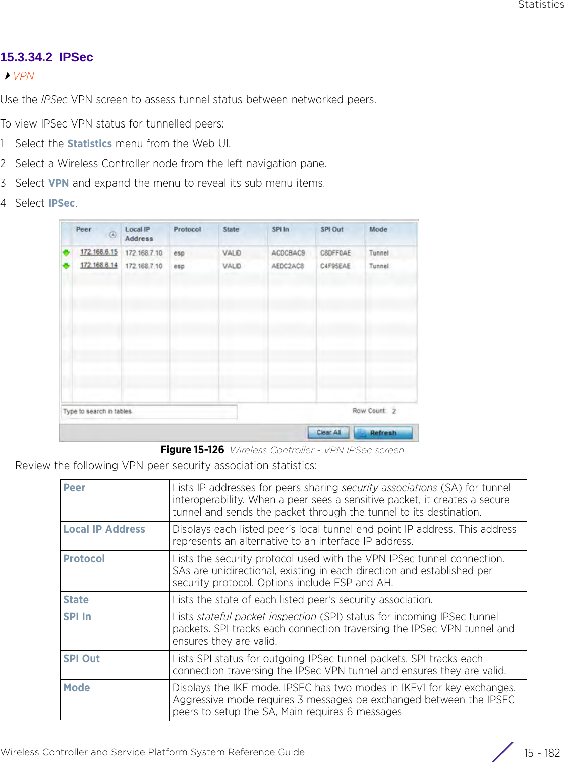
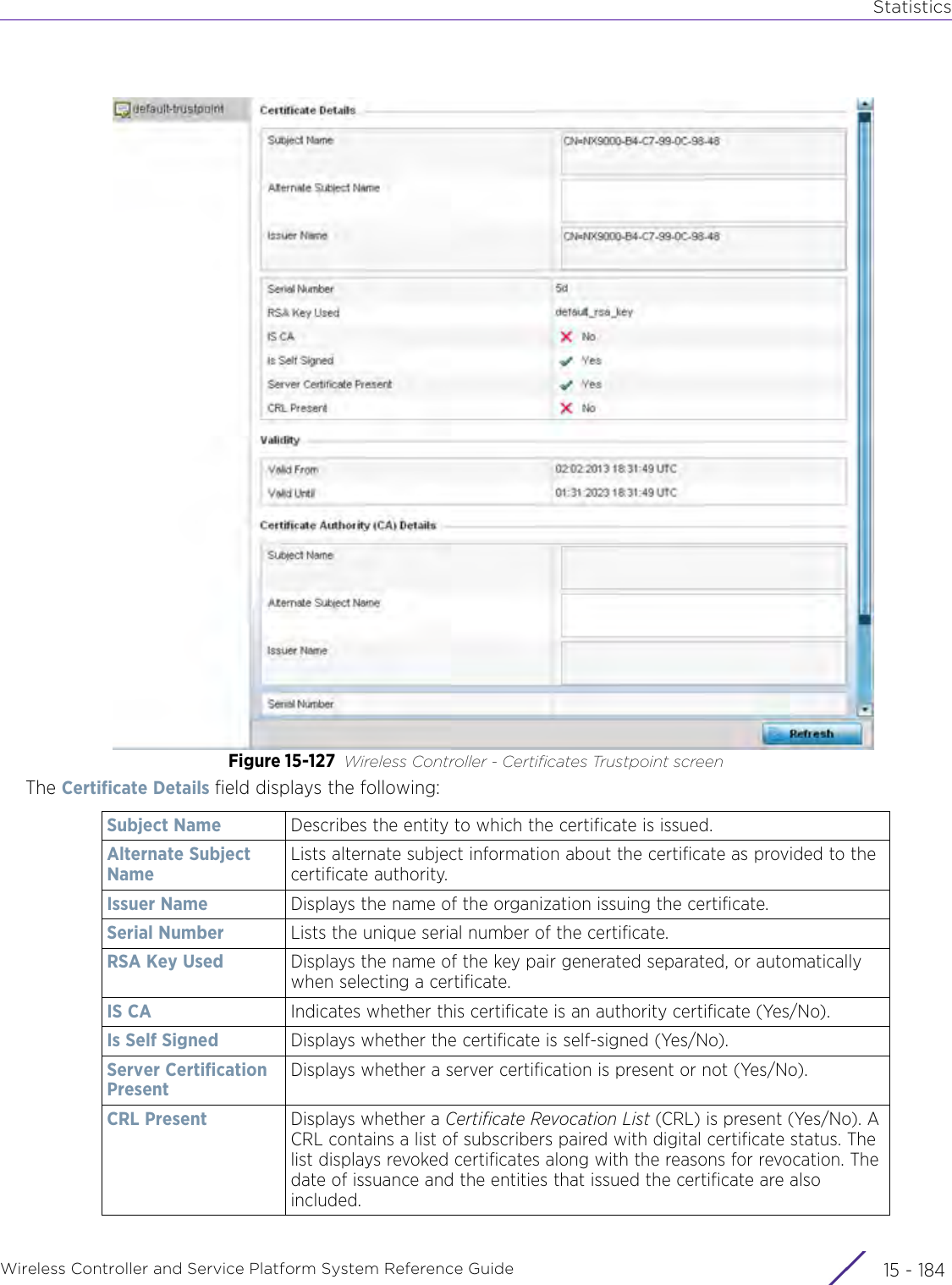
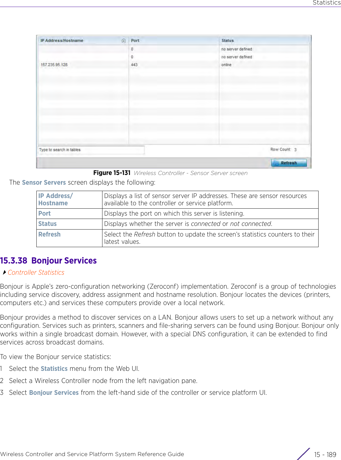
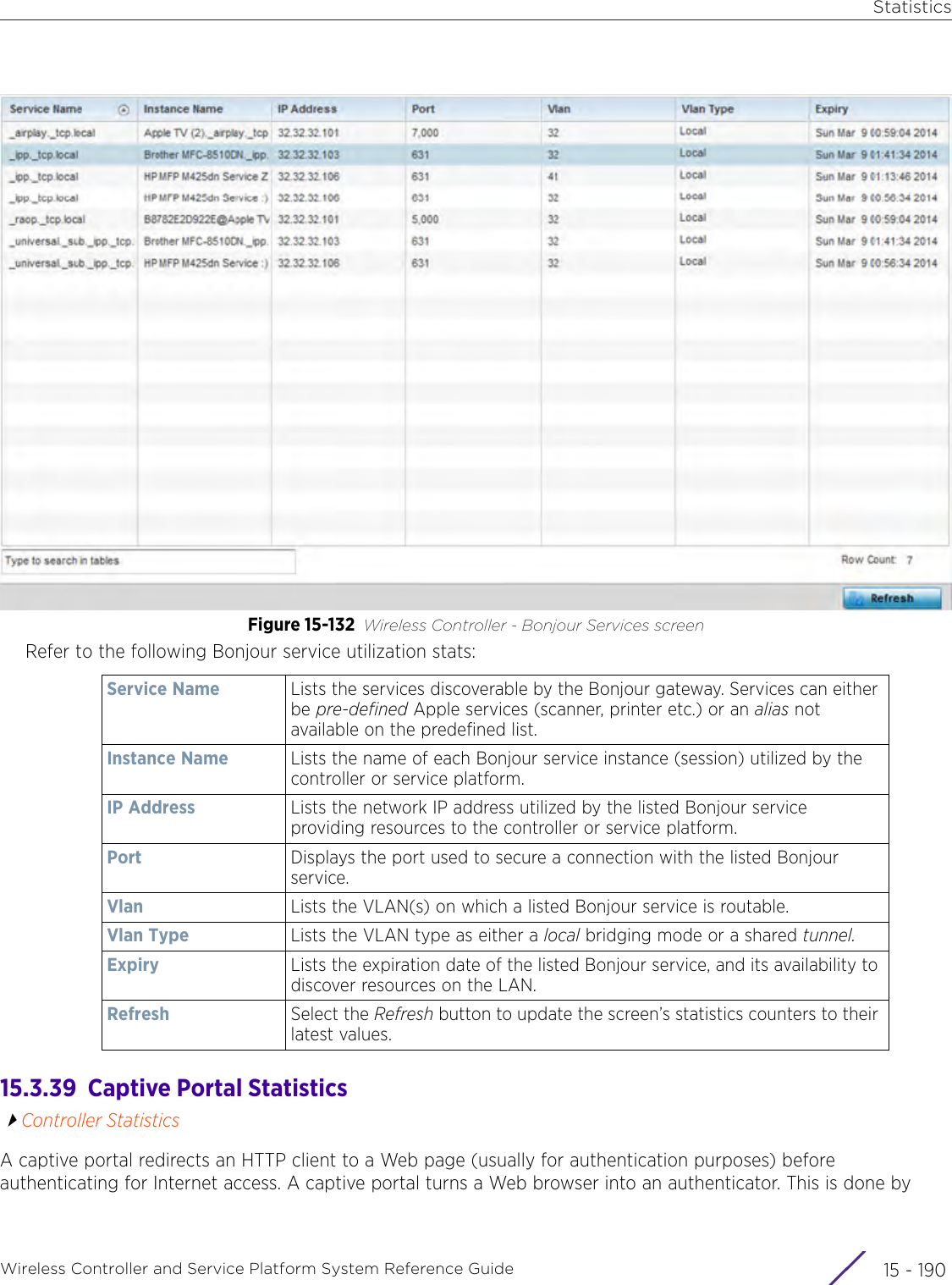
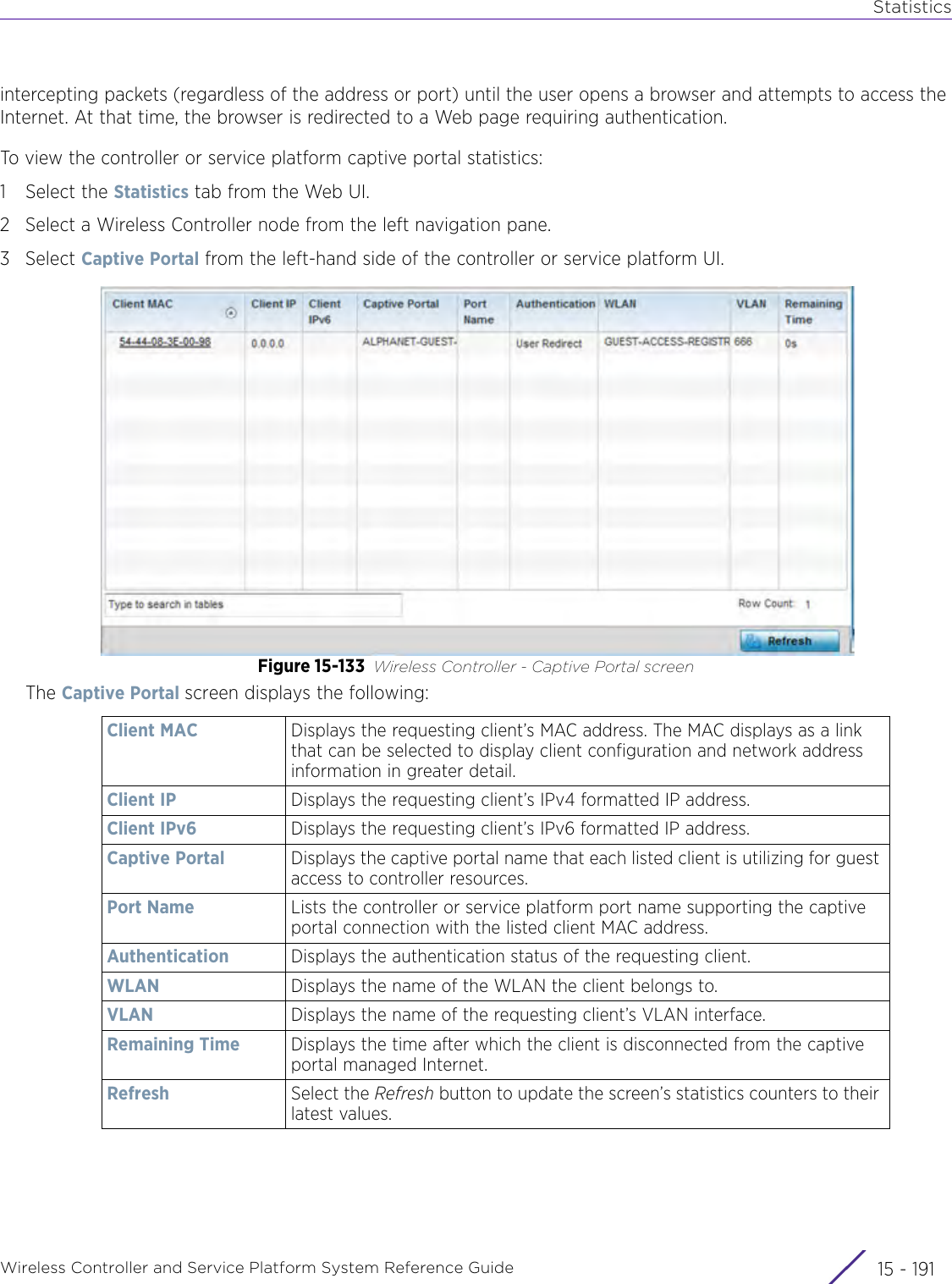
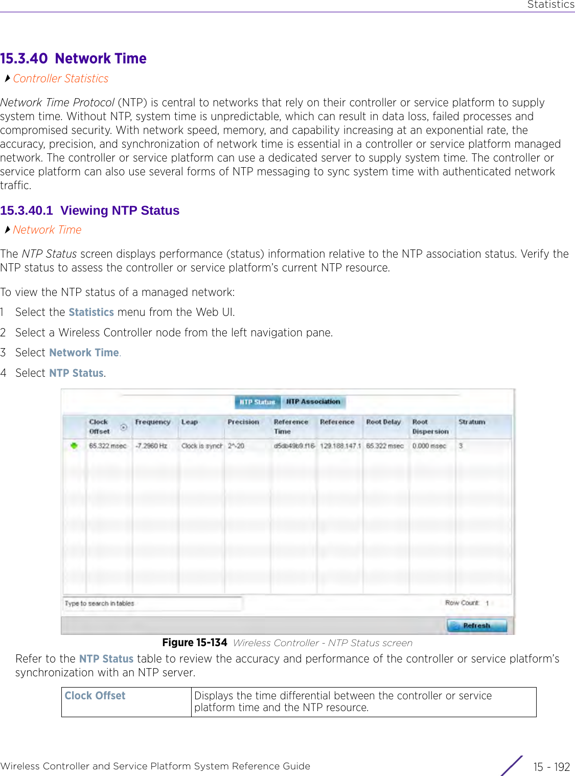
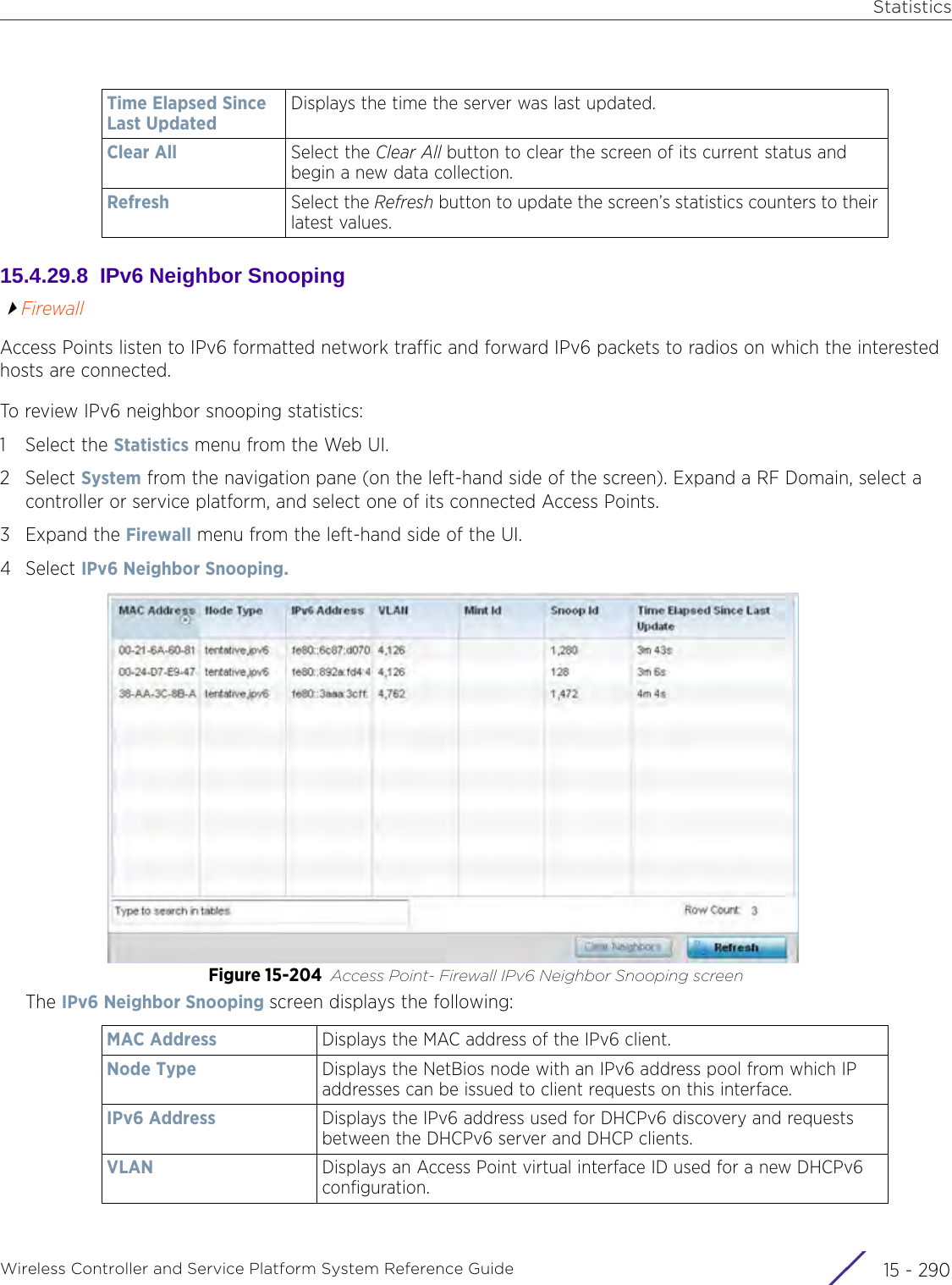
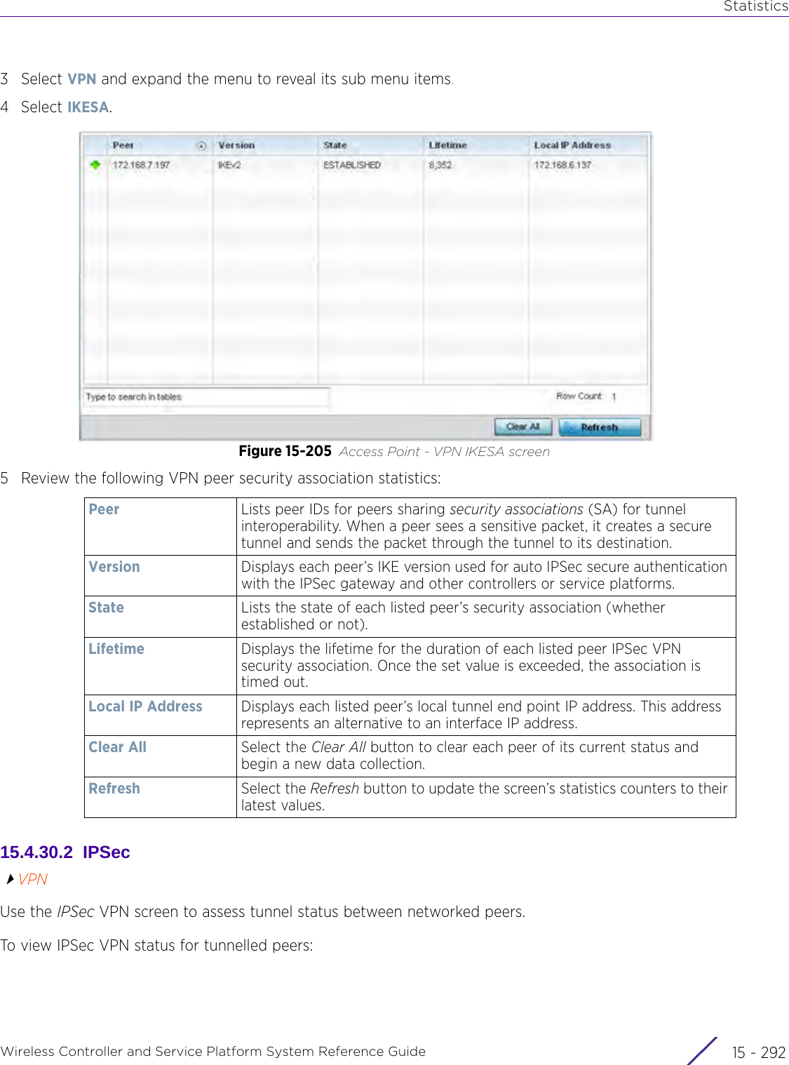
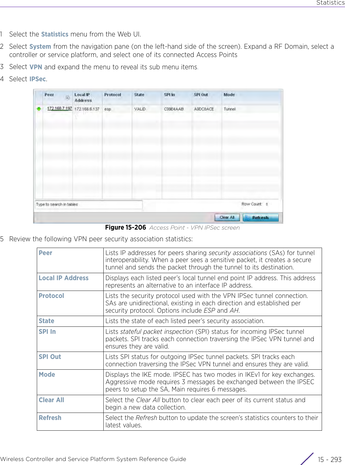
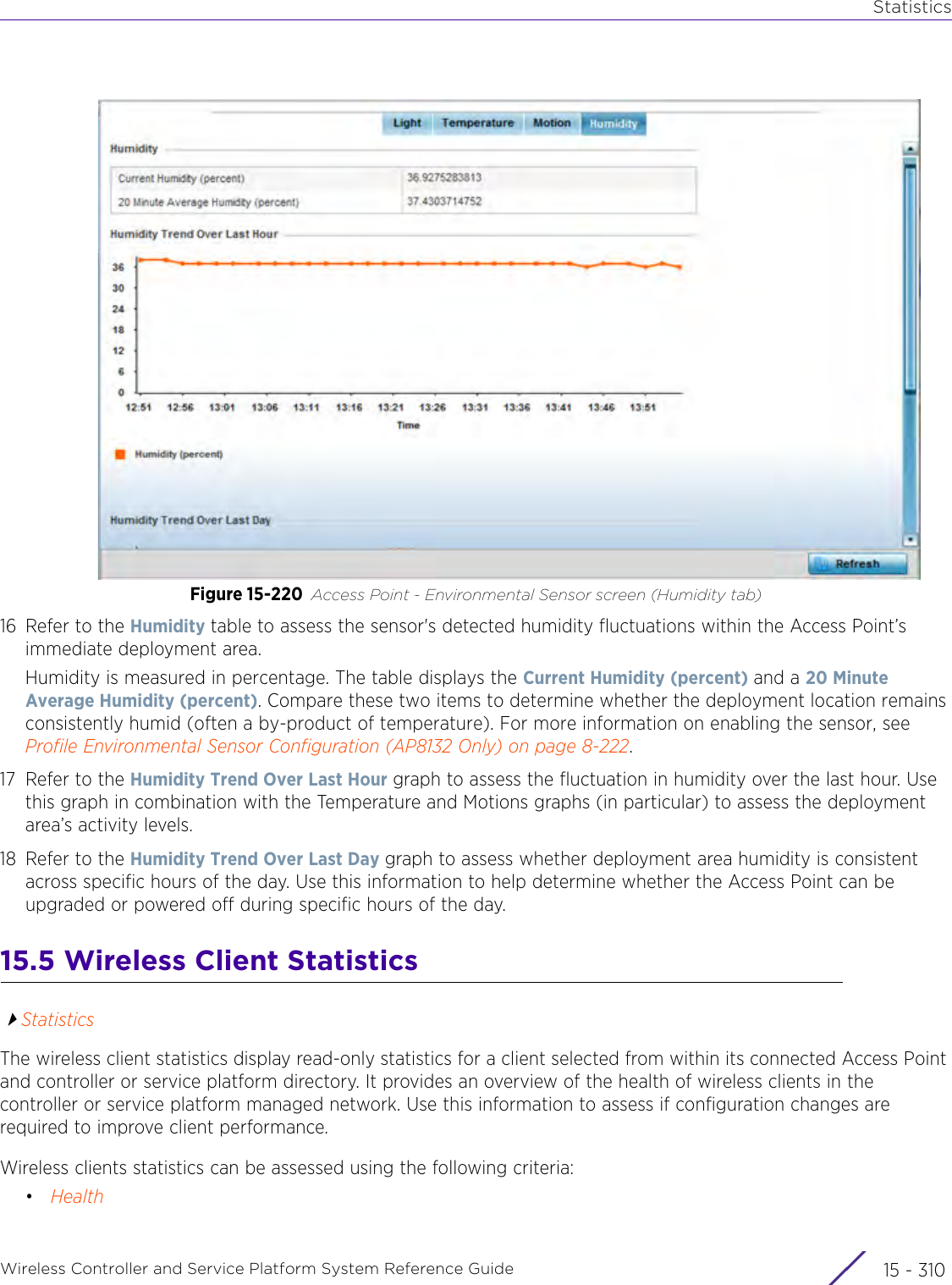
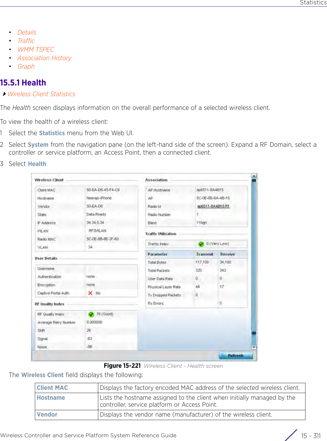
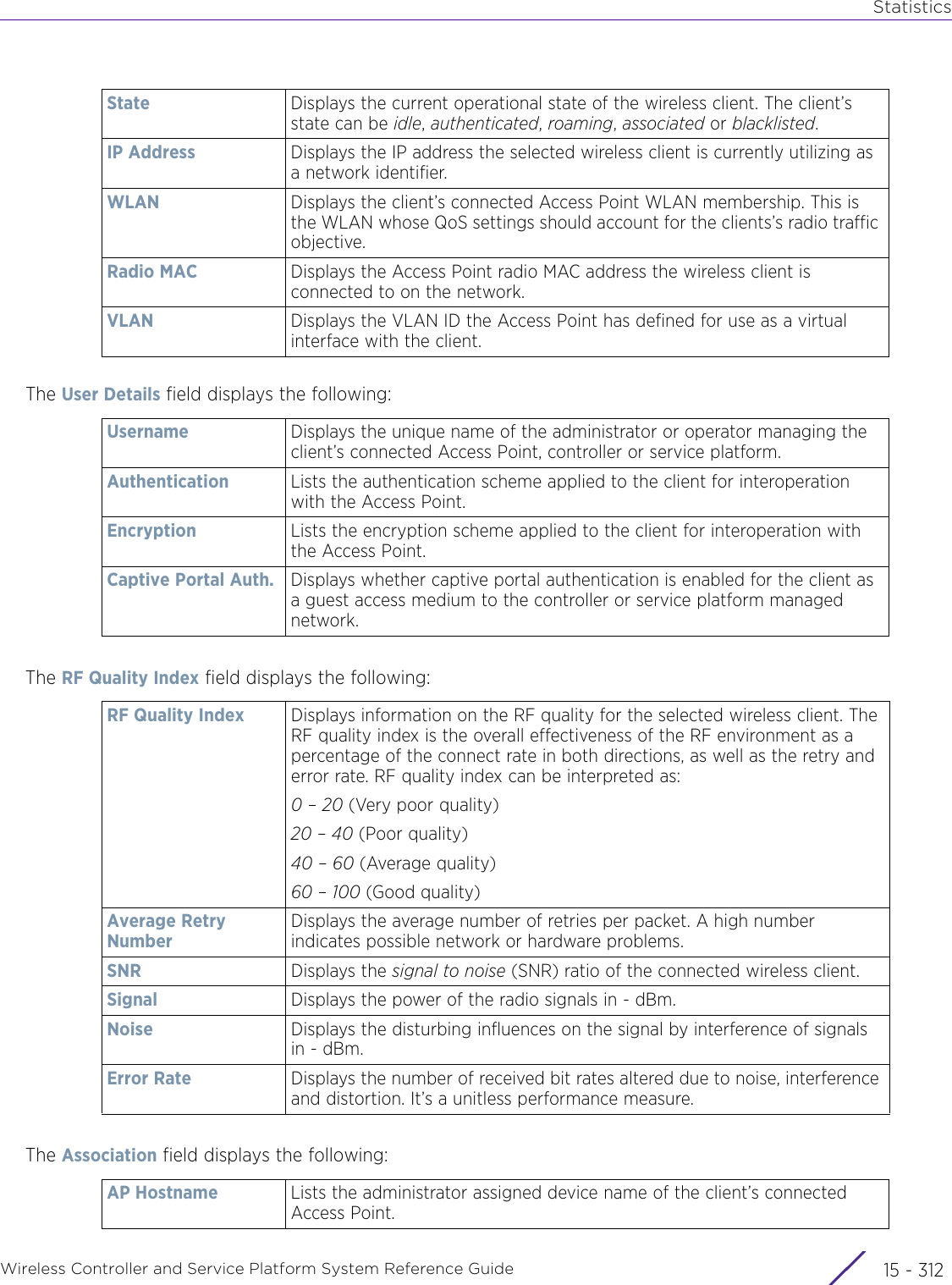
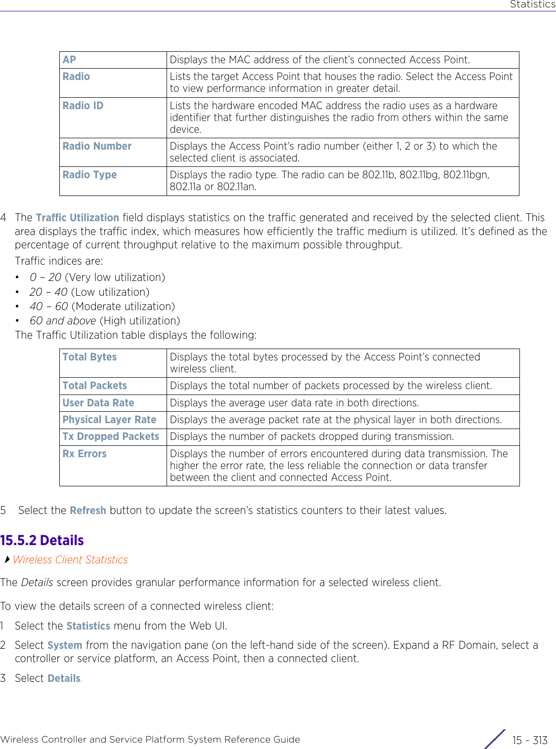
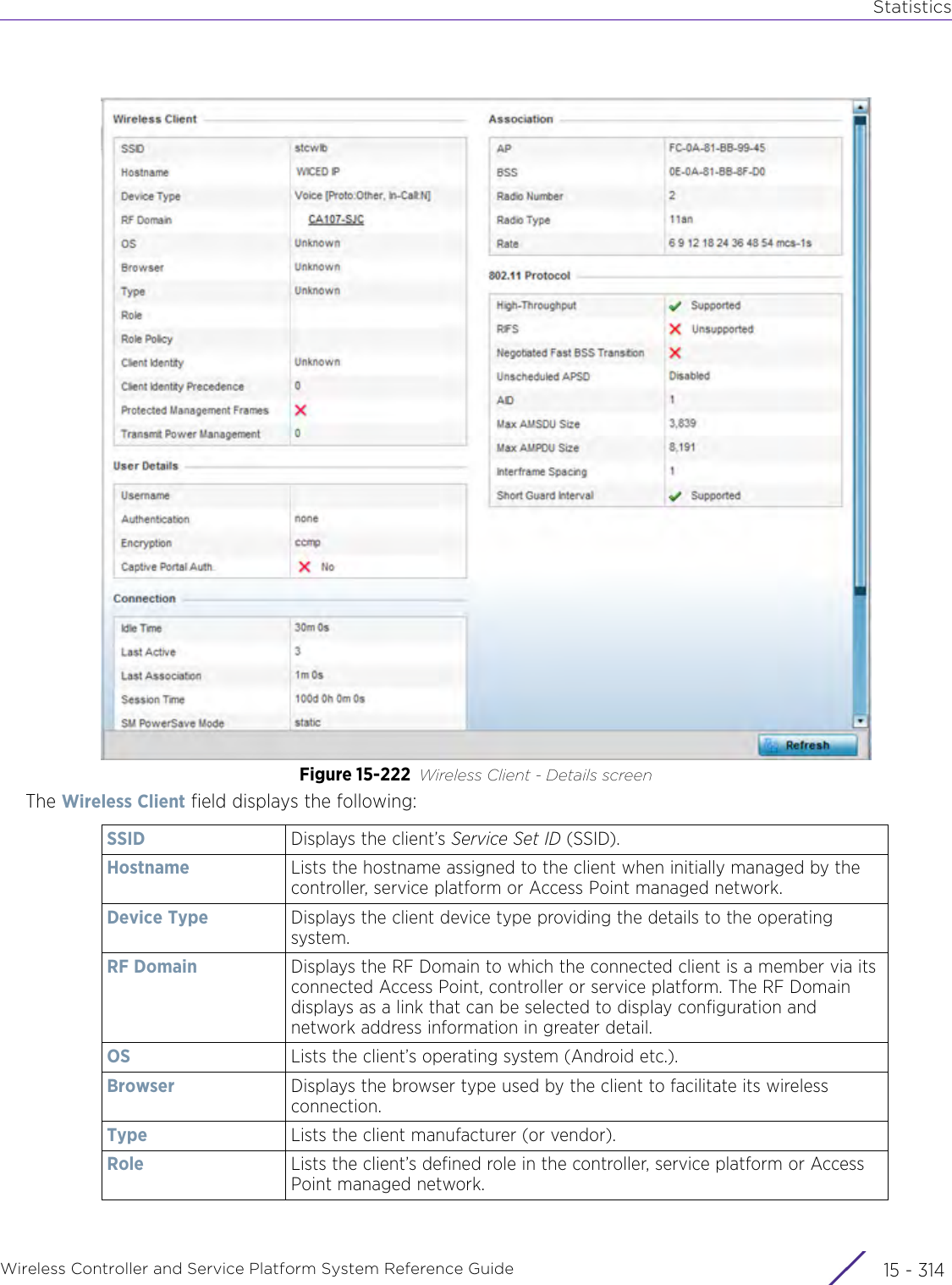
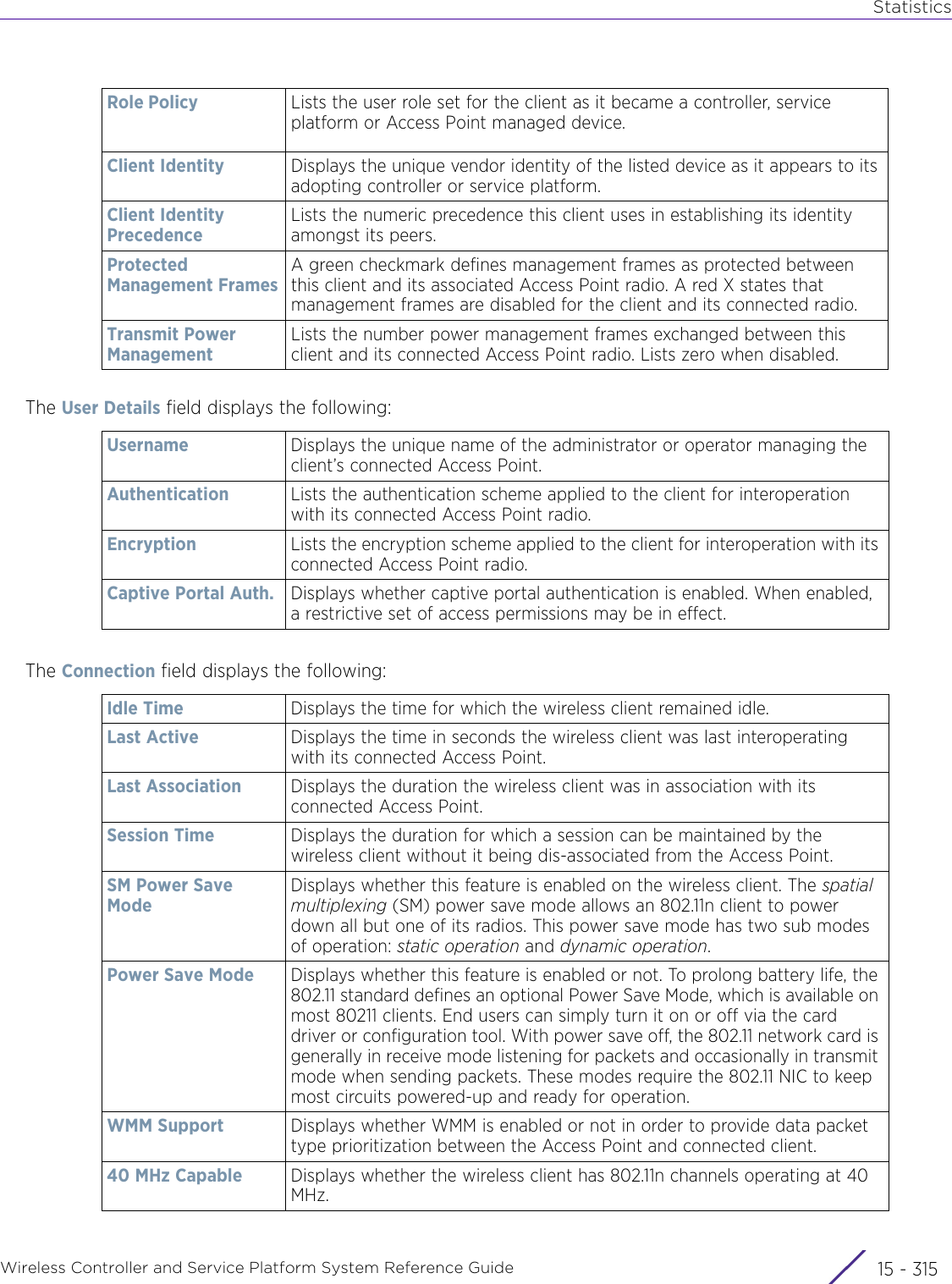
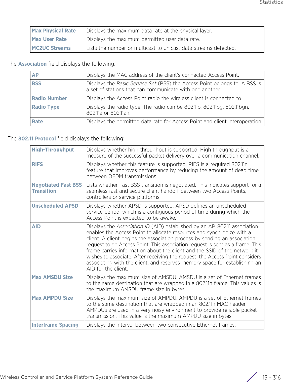
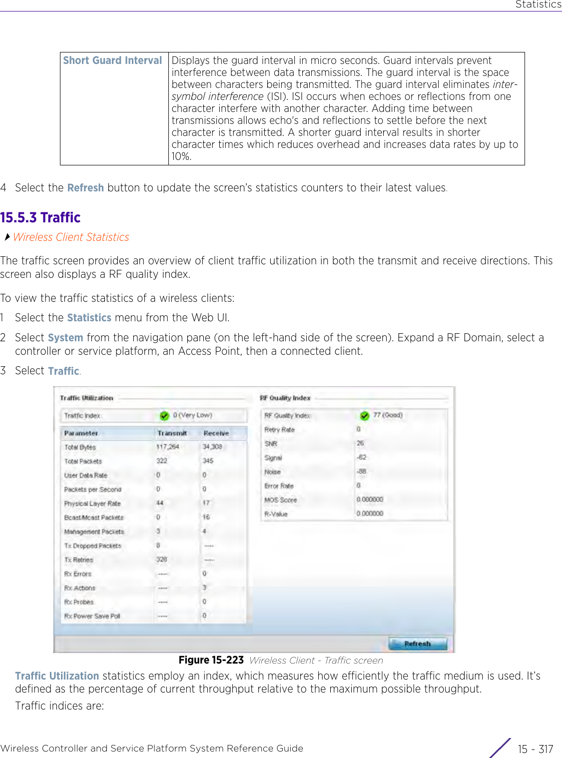
WiNG 5.9.1 System Reference Guide Part 3
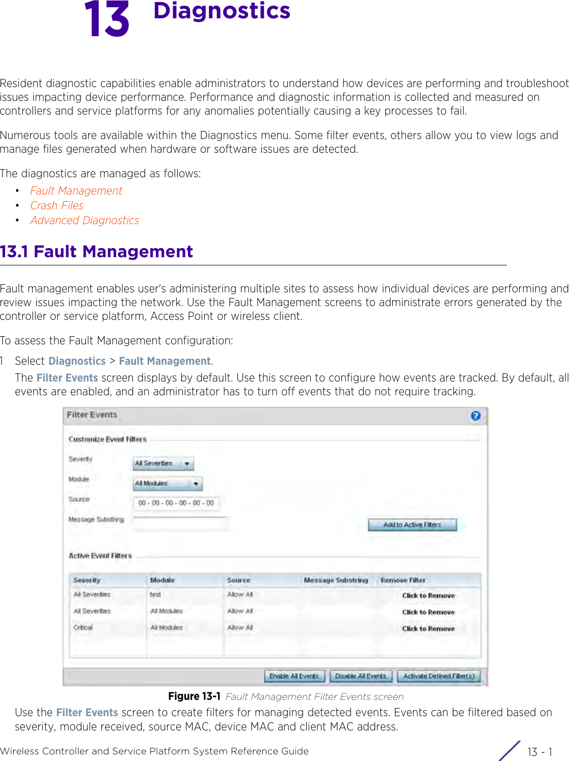
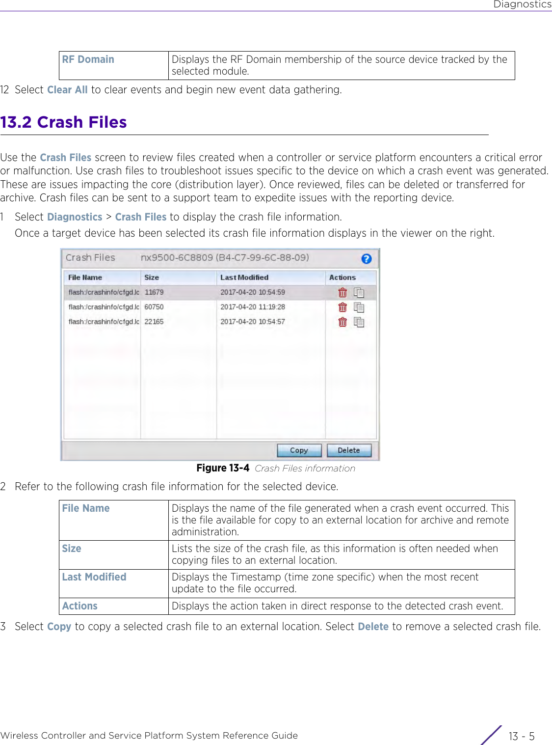
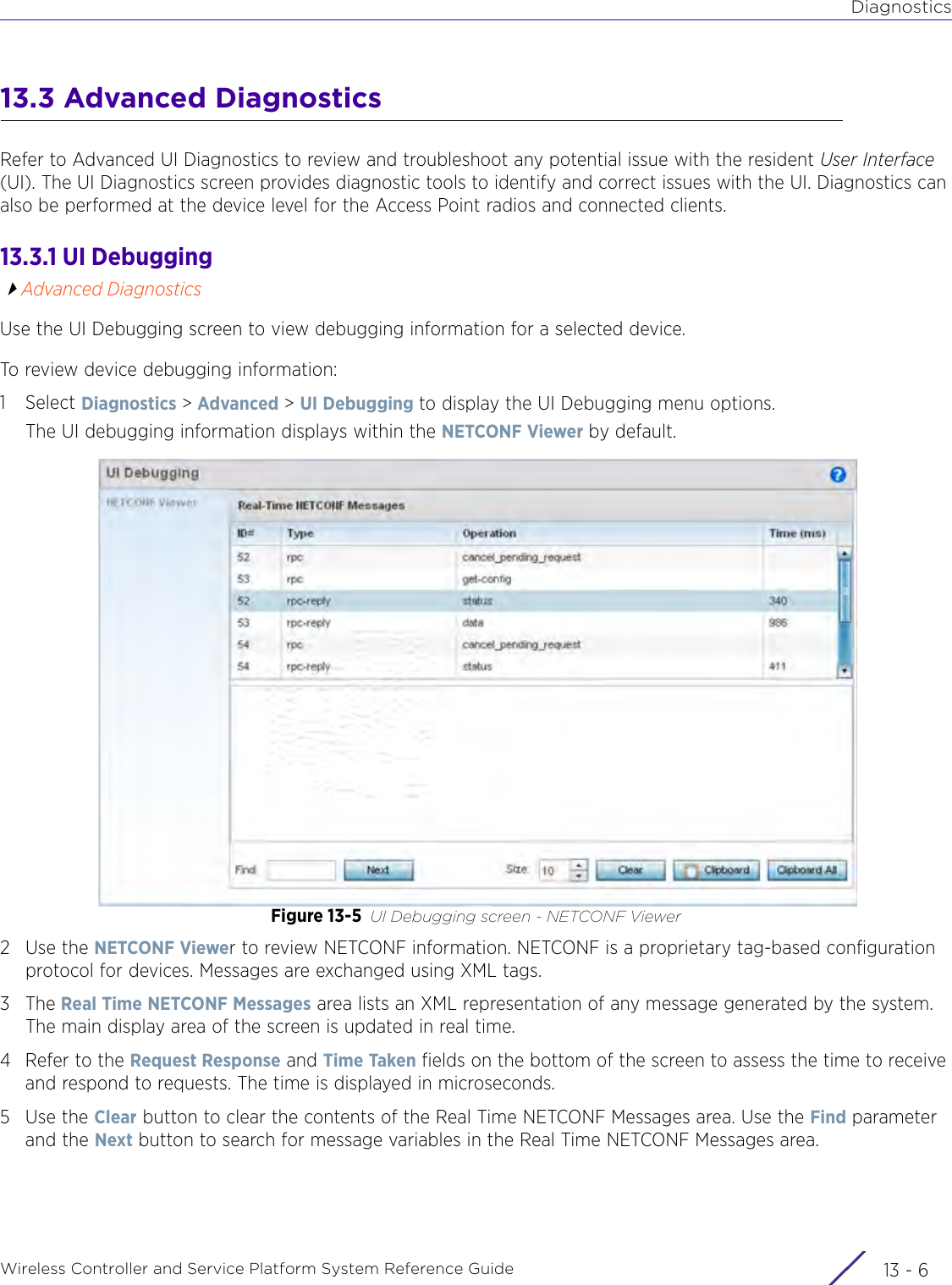
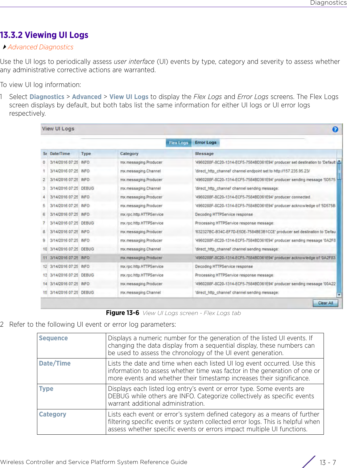
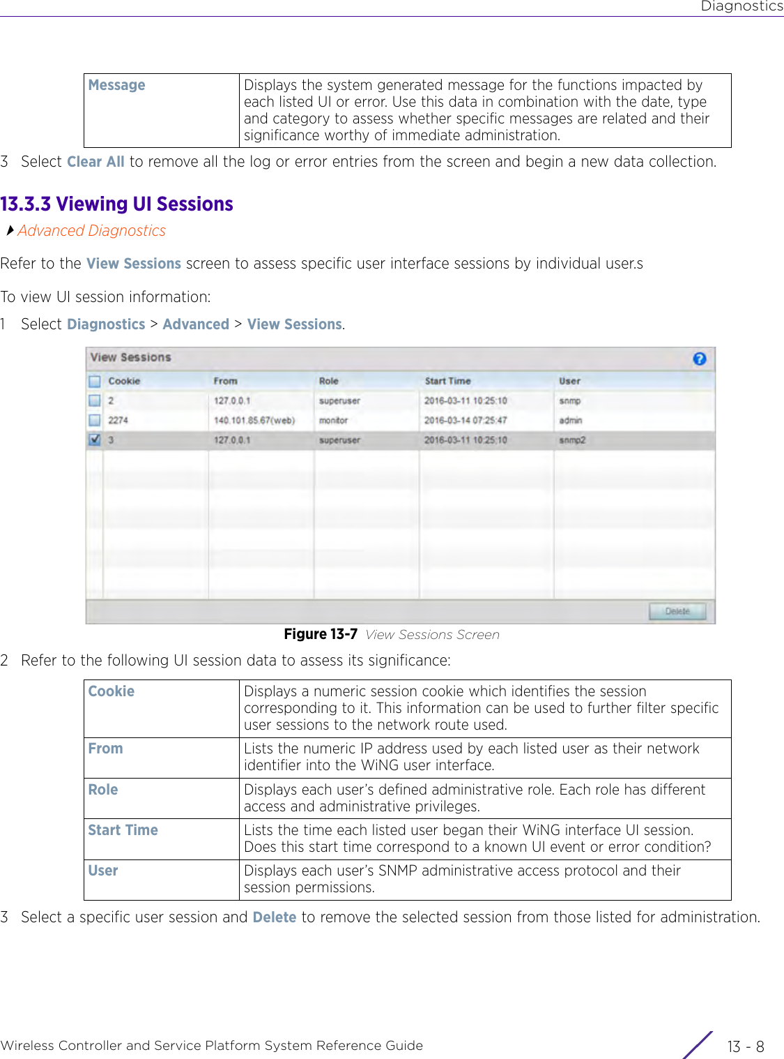
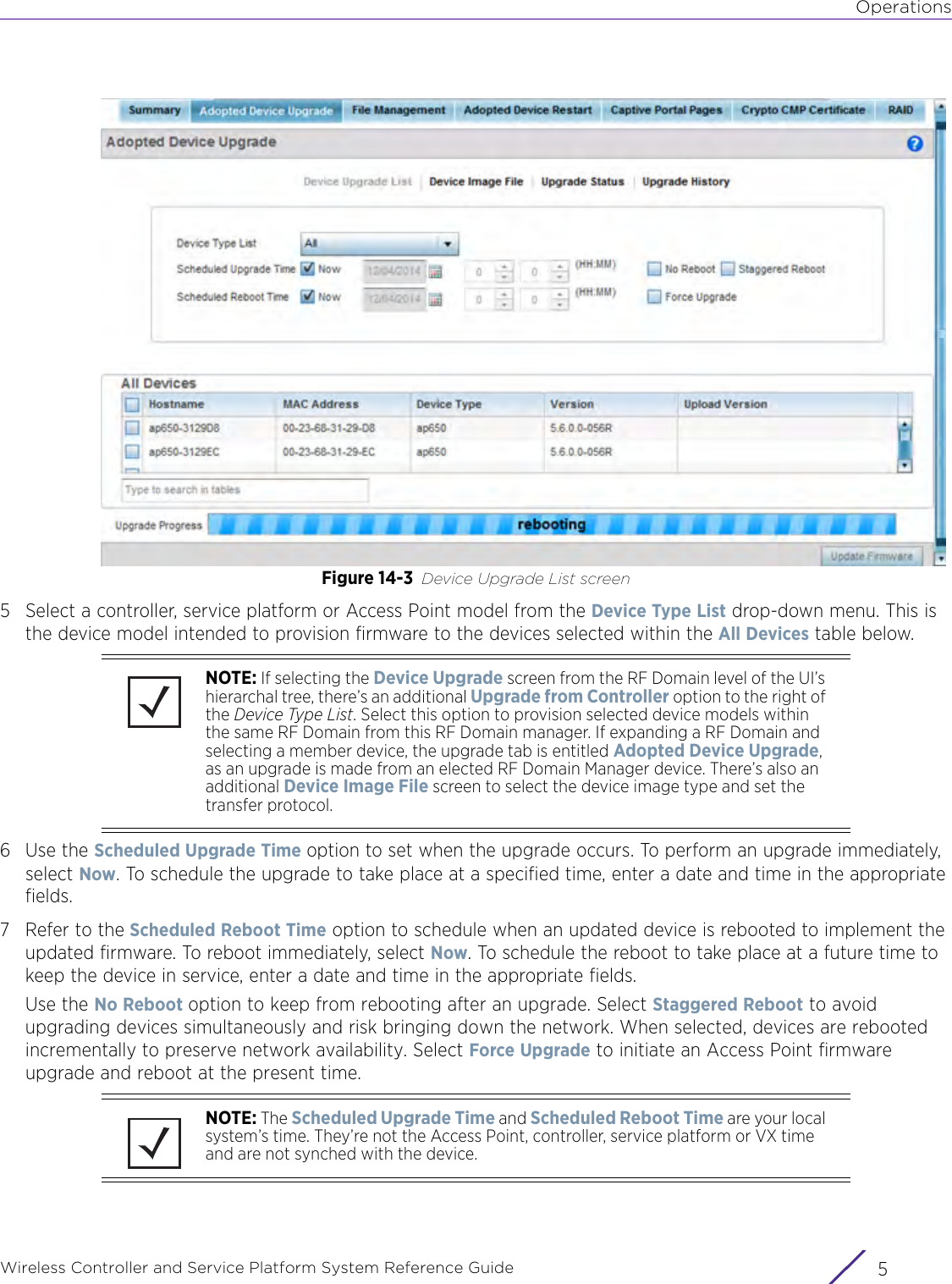
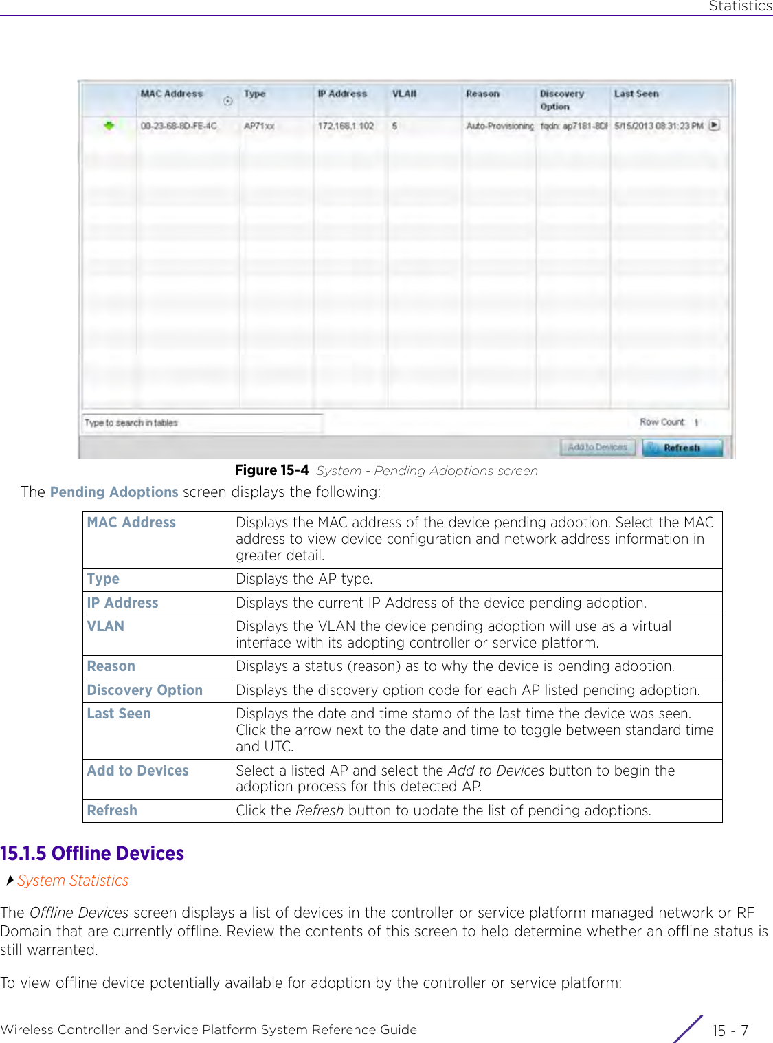
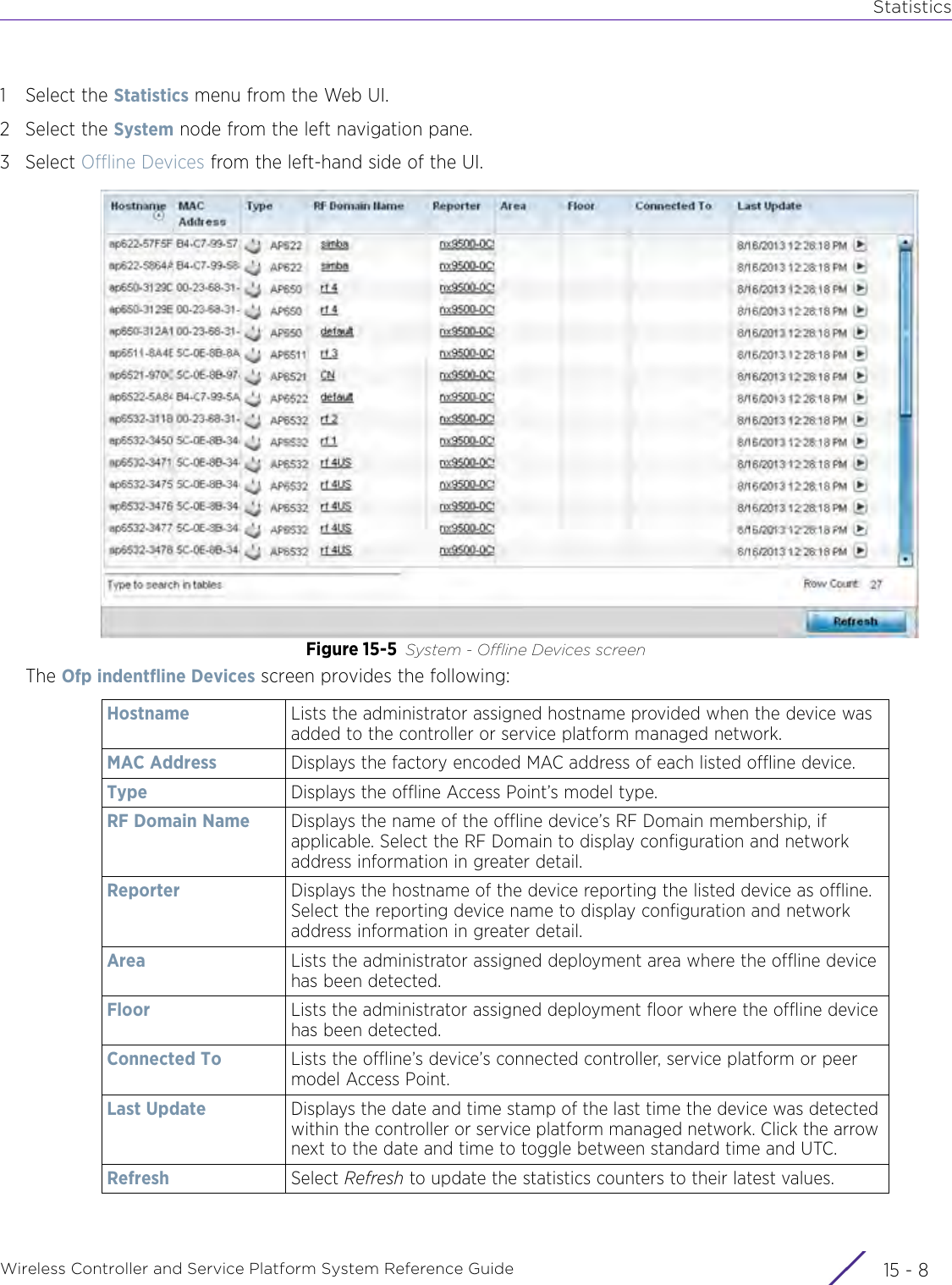
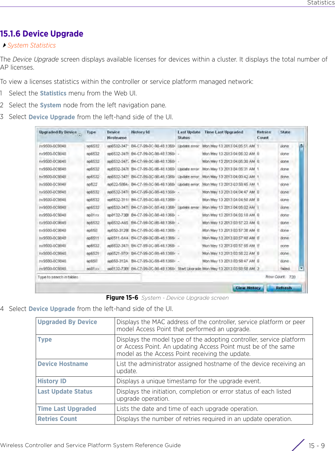
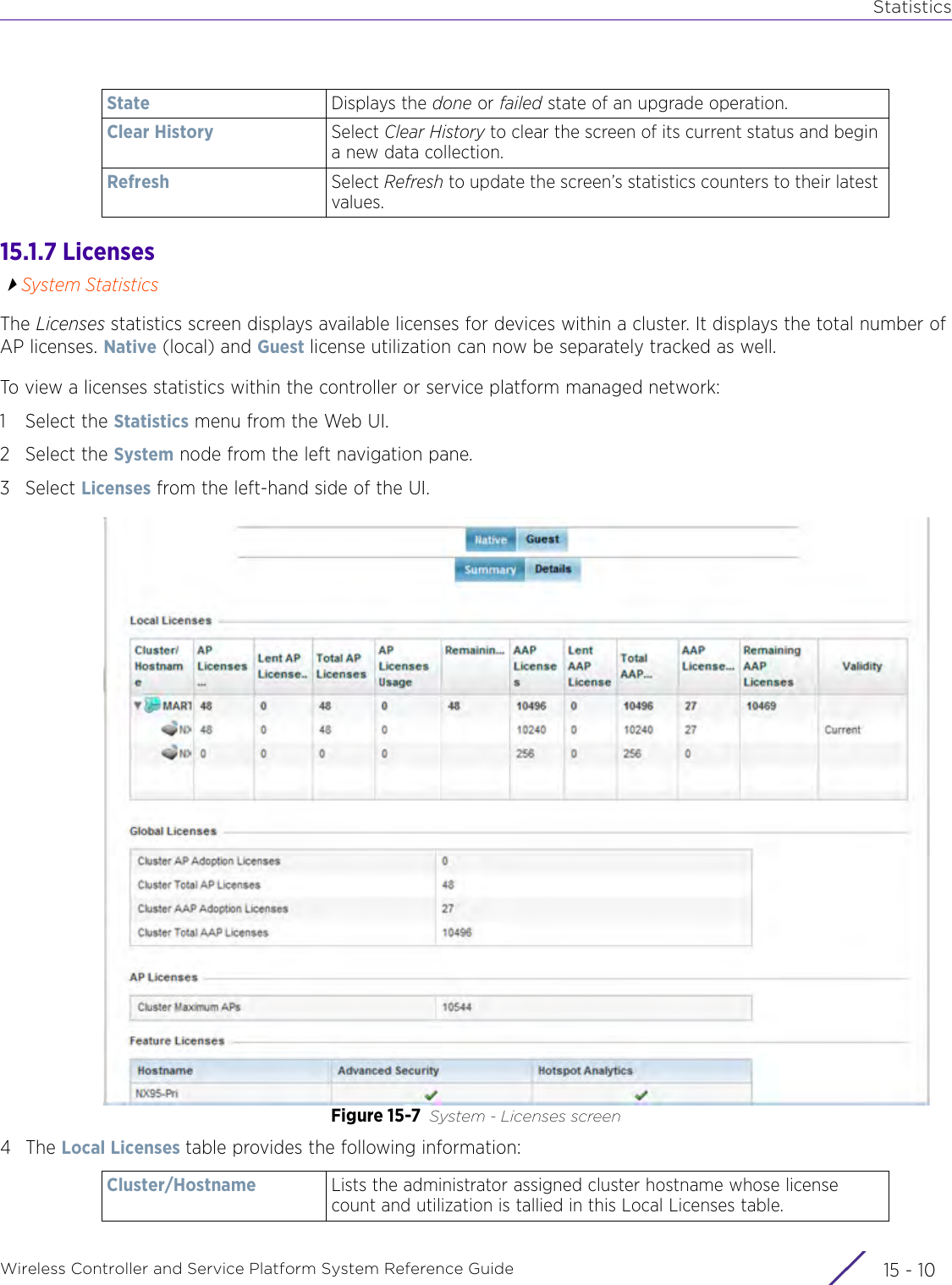
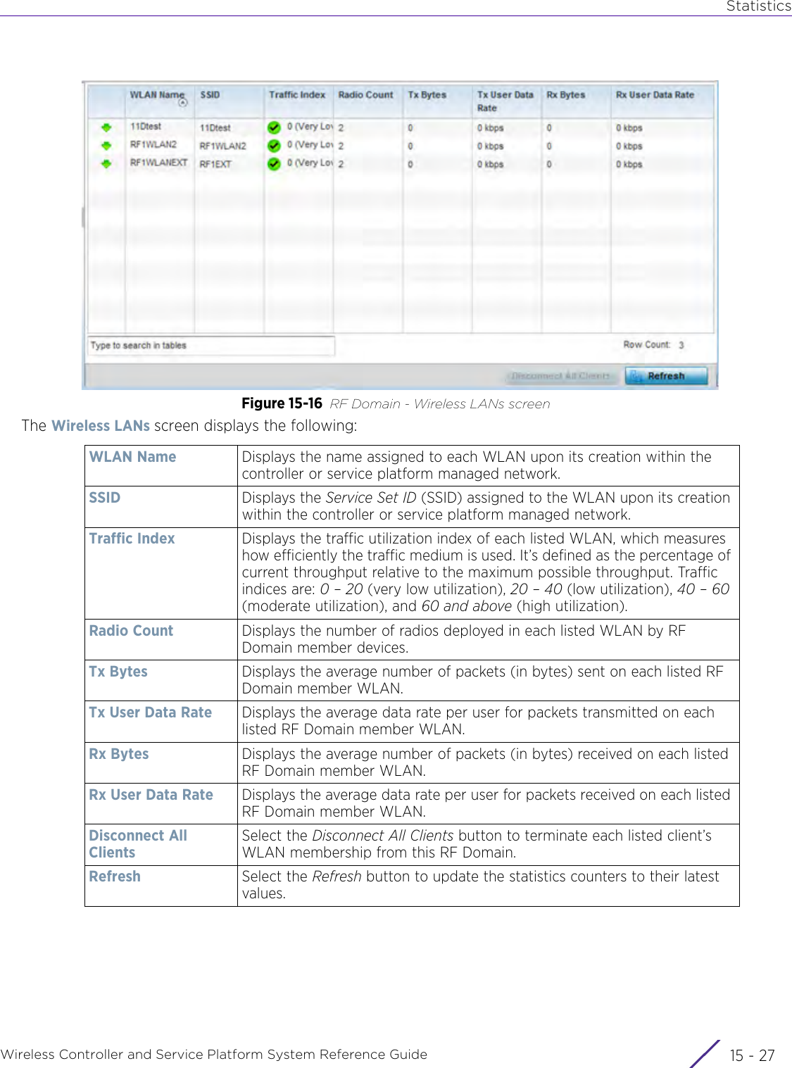
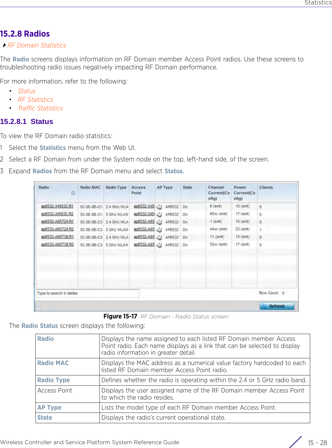
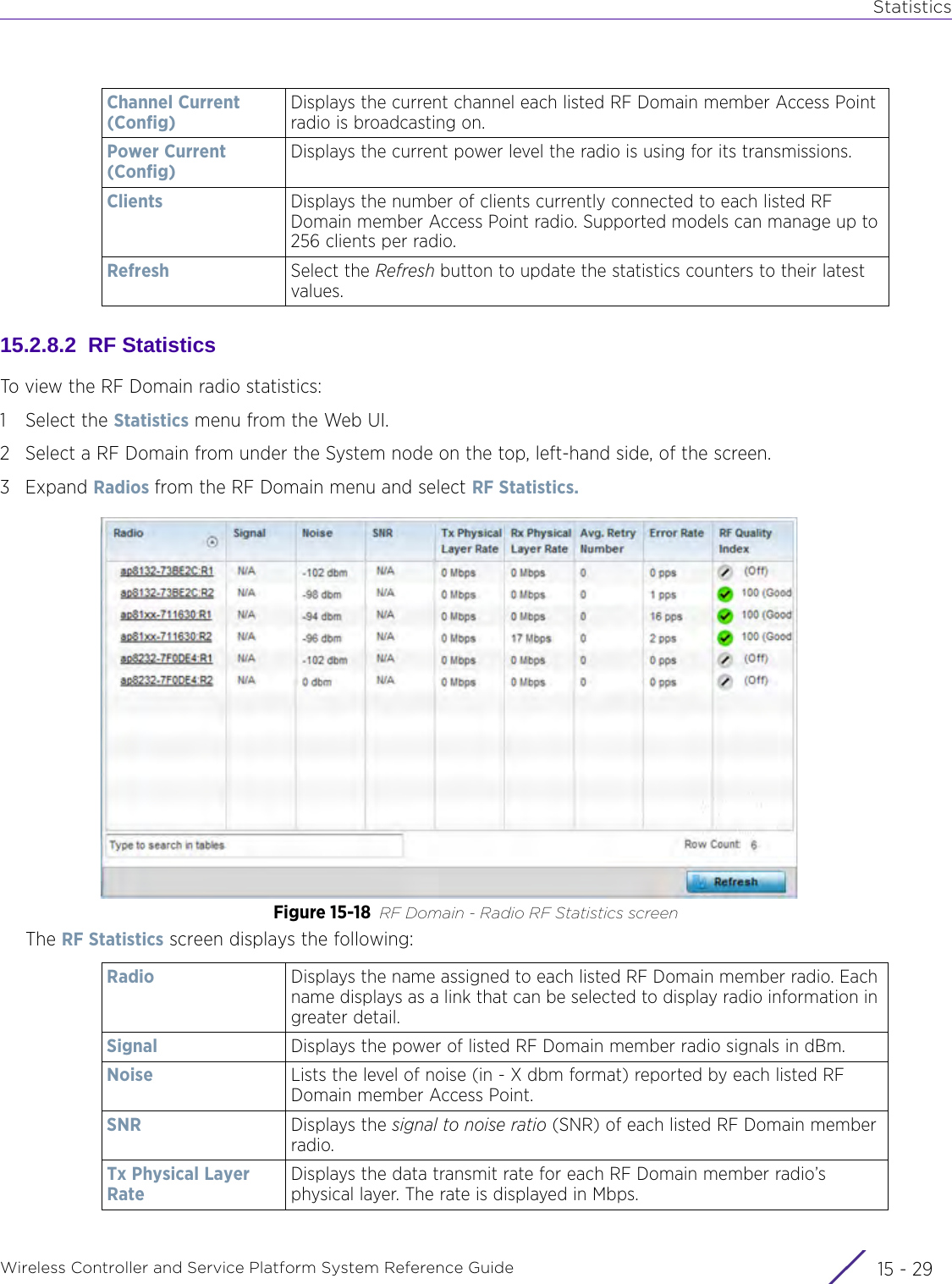
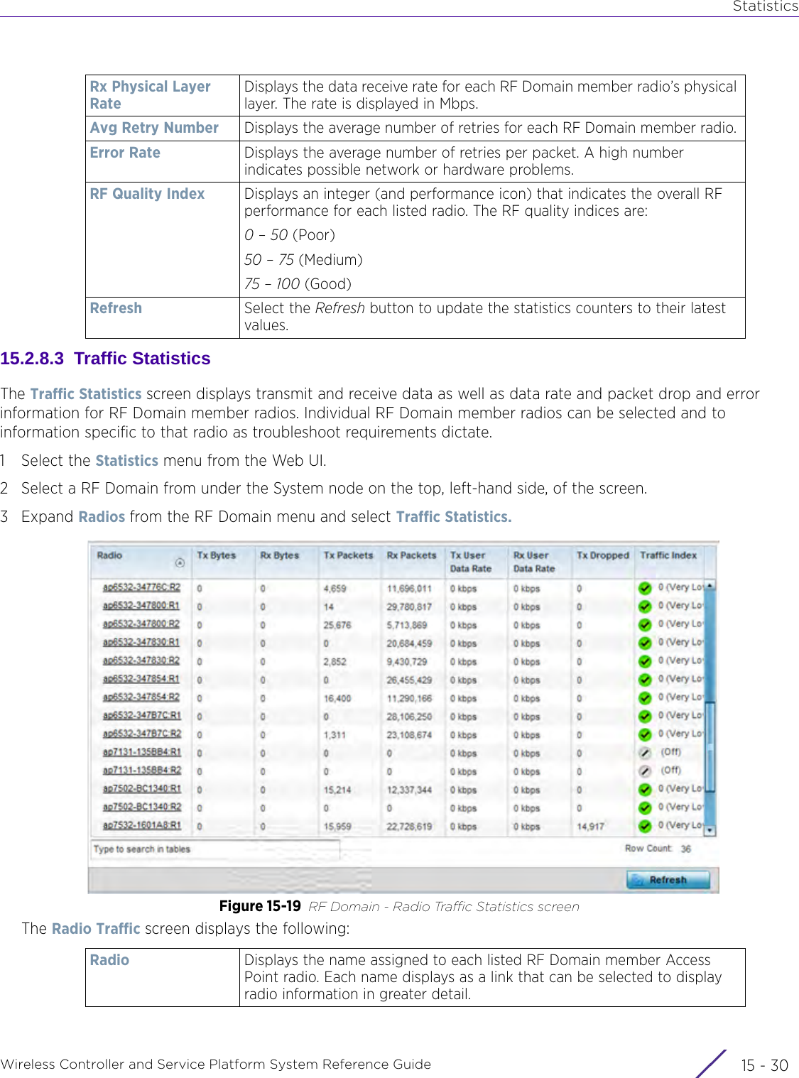


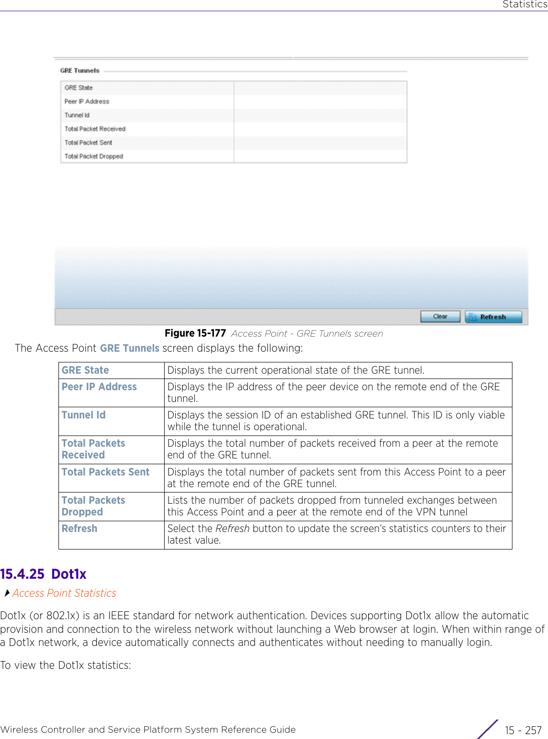
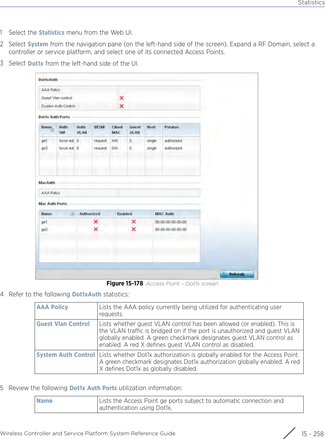
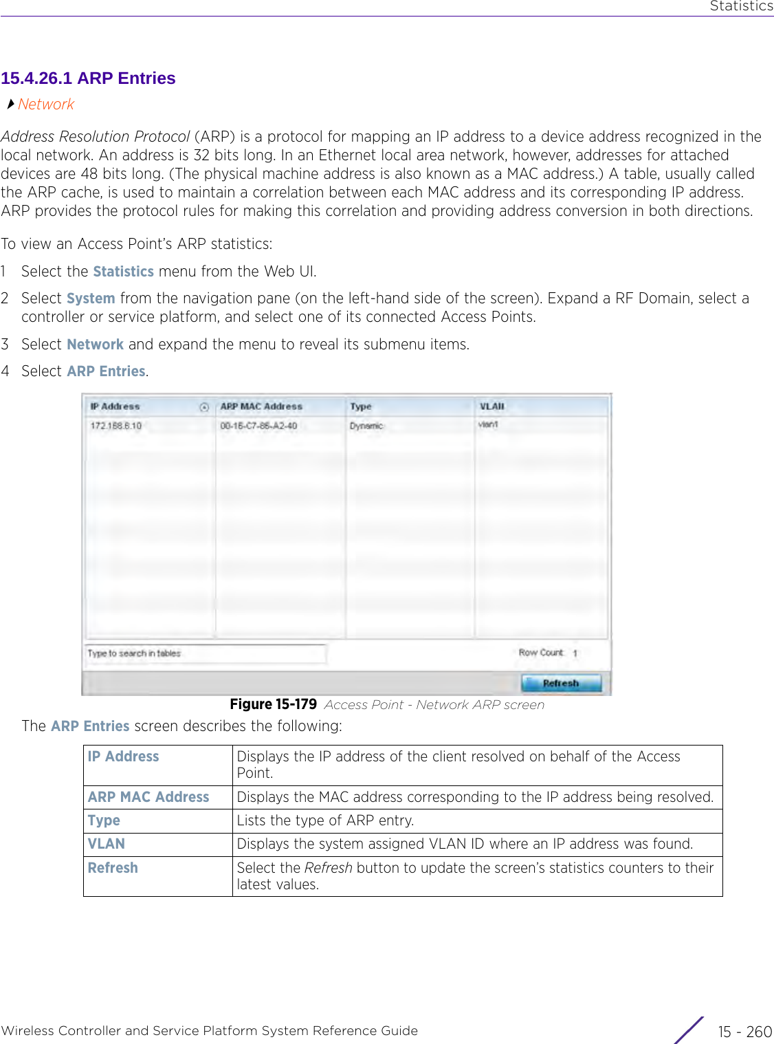

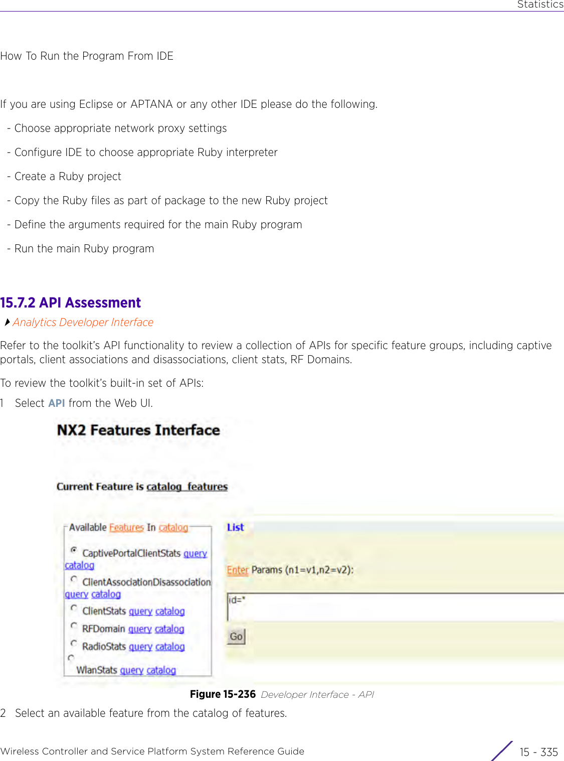
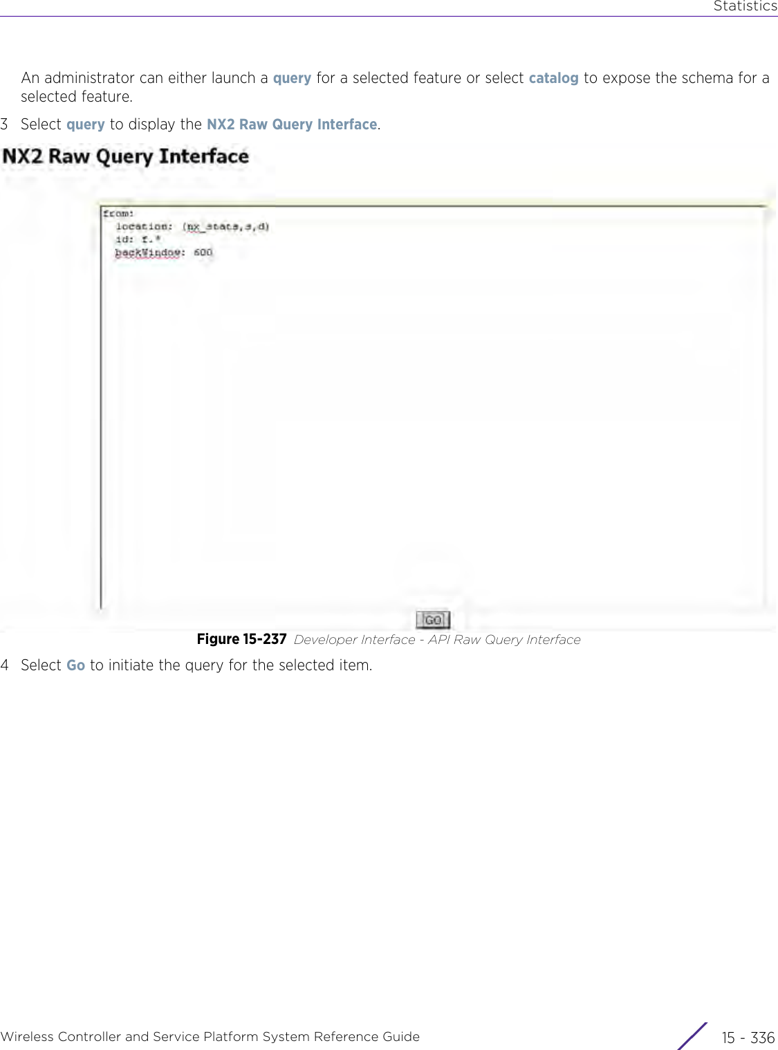
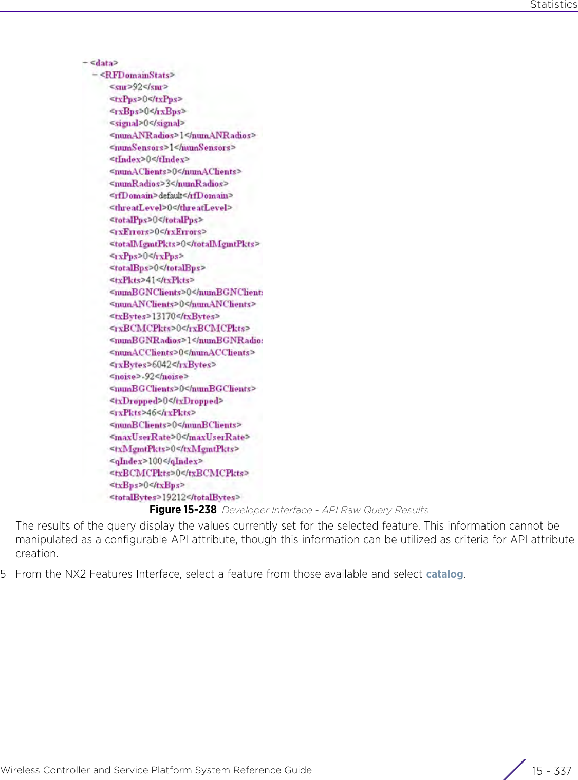
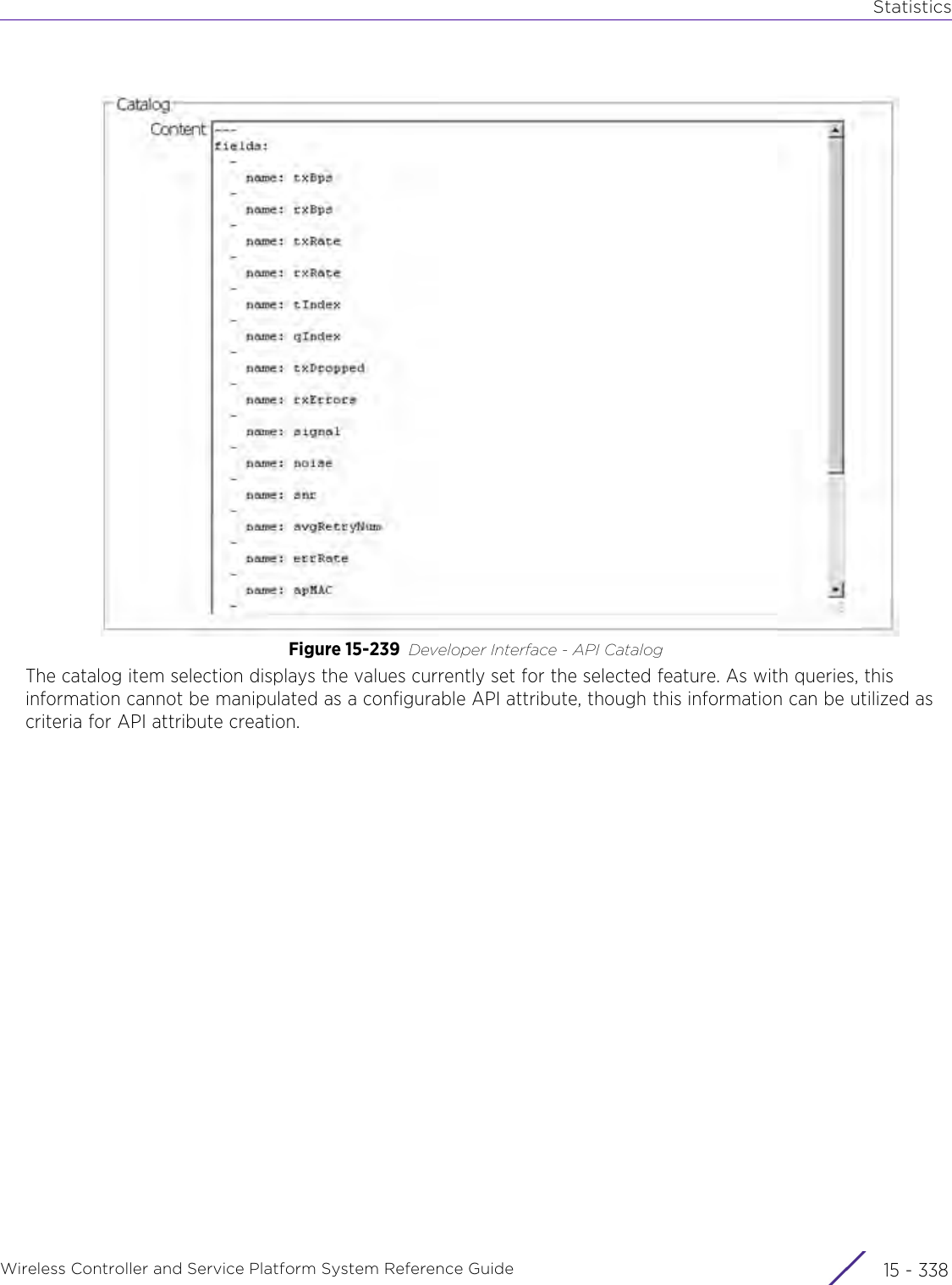
![StatisticsWireless Controller and Service Platform System Reference Guide 15 - 334 Requirements To Run Sample Ruby ClientRuby 2.0 or above. The sample has been tested with Ruby 2.0. To download Ruby use the following:https://www.ruby-lang.org/en/downloads/or http://rubyinstaller.org/Additional Ruby Gems needed to run the sample client are the following. - ipaddress - json - rest-client Please install the gems before running the sample client.How To Run the Program From Command Line ruby NXAStatsClient <IPAddress Of Controller> <Protocol[http|https]> <Port [8080|443]> <Stats_Type>[wlan | rfdomain | radio | client | captive-portal | client-assoc-disassoc] <lookback_duration_in_seconds [ 1 - 2592000]> <username> <password> <number_of_results_to_return [ 1 - 100]> Sample: ruby NXAStatsClient 172.20.33.45 https 443 rfdomain 600 admin admin 30](https://usermanual.wiki/Extreme-Networks/AP3917E.WiNG-5-9-1-System-Reference-Guide-Part-3/User-Guide-3831159-Page-415.png)