Faro Technologies 14000 PORTABLE LASER LINE MEASUREMENT ARM User Manual FARO EDGE Laser ScanArm Users Manual
Faro Technologies, Inc. PORTABLE LASER LINE MEASUREMENT ARM FARO EDGE Laser ScanArm Users Manual
Contents
- 1. Users Manual 1
- 2. Users Manual 2
Users Manual 1

FaroArm®EDGE™ and
ScanArm® Manual
September 2010 - DRAFT
08M52E00_FaroArm_EDGE.book Page 1 Friday, October 1, 2010 11:14 AM
08M52E00_FaroArm_EDGE.book Page 2 Friday, October 1, 2010 11:14 AM
©FARO Technologies, Inc., 2010. All rights reserved.
No part of this publication may be reproduced, or transmitted in any form or by
any means without written permission of FARO Technologies Inc.
FARO TECHNOLOGIES INC. MAKES NO WARRANTY, EITHER
EXPRESS OR IMPLIED, INCLUDING BUT NOT LIMITED TO ANY
IMPLIED WARRANTIES OF MERCHANTABILITY OR FITNESS FOR A
PARTICULAR PURPOSE, REGARDING THE FAROARM AND ITS
MATERIALS, AND MAKES SUCH MATERIALS AVAILABLE SOLELY ON
AN “AS-IS” BASIS.
IN NO EVENT SHALL FARO TECHNOLOGIES INC. BE LIABLE TO
ANYONE FOR SPECIAL, COLLATERAL, INCIDENTAL, OR
CONSEQUENTIAL DAMAGES IN CONNECTION WITH OR ARISING
OUT OF THE PURCHASE OR USE OF THE FAROARM OR ITS
MATERIALS. THE SOLE AND EXCLUSIVE LIABILITY TO FARO
TECHNOLOGIES INC., REGARDLESS OF THE FORM OF ACTION,
SHALL NOT EXCEED THE PURCHASE PRICE OF THE MATERIALS
DESCRIBED HEREIN.
THE INFORMATION CONTAINED IN THIS MANUAL IS SUBJECT TO
CHANGE WITHOUT NOTICE AND DOES NOT REPRESENT A
COMMITMENT ON THE PART OF FARO TECHNOLOGIES INC.
ACCEPTANCE OF THIS DOCUMENT BY THE CUSTOMER
CONSTITUTES ACKNOWLEDGMENT THAT IF ANY INCONSISTENCY
EXISTS BETWEEN THE ENGLISH AND NON-ENGLISH VERSIONS, THE
ENGLISH VERSION TAKES PRECEDENCE.
FARO® FaroArm® FARO Laser ScanArm® and CAM2® are registered
trademarks of FARO Technologies, Inc.
Acrobat® is a registered trademark of Adobe Systems, Inc.
Bluetooth® is a registered trademark of Bluetooth SIG, Inc.
FARO Technologies, Inc. Internal Control File Locations:
\CONTROL\REFERENC\08PRODUC\ENGLISH\Prdpub46\08m46e00 - EDGE Manual - September 2010 - DRAFT.pdf
\CONTROL\RECORDS\05MANUFA\PARTSPEC\XH17-0258.pdf
08M52E00_FaroArm_EDGE.book Page 3 Friday, October 1, 2010 11:14 AM
08M52E00_FaroArm_EDGE.book Page 4 Friday, October 1, 2010 11:14 AM
FaroArm®EDGE™ Manual
September 2010 - DRAFT
i
Table of Contents
Chapter 1 : Introduction
General Information........................................................ 3
Regulatory Information ................................................... 4
Product Environmental Information .............................. 7
Precautions ...................................................................... 8
Chapter 2 : Setup
The EDGE Packing Contents .......................................... 9
Packing the EDGE ......................................................... 10
Hardware Setup............................................................. 11
Mounting the Base ........................................................................ 11
Surface Mount Plate Dimensions...............................................12
7-Axis Handle.................................................................................. 14
EDGE Power Supply....................................................... 14
Supplying Power to the EDGE ...................................................... 14
EDGE Battery Pack ........................................................................ 15
Installing the Battery Pack ......................................................... 16
Removing the Battery Pack ...................................................... 16
Charging the Battery Pack ....................................................... 16
Fold-Down Touch Screen Controller ........................... 17
Host Computer .............................................................. 17
Wired connections ........................................................................ 17
Ethernet ....................................................................................... 18
Wireless Connections .................................................................... 18
FARO Wireless - Bluetooth.......................................................... 19
FARO Wireless - WLAN................................................................ 22
Wireless Zero Configuration Reference ................................... 26
Auxiliary Port (7th Variable Options Port).................... 27
Chapter 3 : Operation
Numerical and Signal Processing ................................ 29
Handle LED ..................................................................................... 29
Error and Status Indicators ............................................................ 30
Referencing the Encoders............................................................ 31
08M52E00_FaroArm_EDGE.book Page i Friday, October 1, 2010 11:14 AM
FaroArm®EDGE™ Manual
September 2010 - DRAFT
ii
EDGE Handle Buttons.................................................... 32
Chapter 4 : Probes
EDGE Probes .................................................................. 35
Custom Probes............................................................................... 36
Installing Probes ............................................................................. 36
Renishaw TP-20 Probe Installation and Operation .... 37
Custom Probe Calibration............................................ 40
FARO Laser Line Probe.................................................. 40
Laser Safety .................................................................................... 40
Laser Radiation Emission ............................................................... 41
Serial Number Label ...................................................................... 42
Servicing ......................................................................................... 42
Hardware Installation .................................................................... 43
Holding the FARO Laser Line Probe............................................. 45
Hardware Controls and Indicators .............................................. 45
Buttons ..........................................................................................45
LEDs ...............................................................................................46
Range Finder................................................................................46
Software Setup............................................................................... 47
Calibration...................................................................................... 47
Sphere Calibration ......................................................................49
Plane Calibration ........................................................................52
DRO ................................................................................................. 56
FARO Laser Line Probe Settings.................................................... 57
Line Probe Settings ......................................................................58
Additional Considerations..........................................................62
Chapter 5 : Accuracy
Calibration and Certification....................................... 67
EDGE Calibration ........................................................................... 67
EDGE Certification......................................................................... 68
Repeatability .............................................................................. 68
Volumetric Accuracy ................................................................ 69
EDGE Performance ....................................................... 70
Loss of a Degree of Freedom....................................................... 71
Chapter 6 : Maintenance and
08M52E00_FaroArm_EDGE.book Page ii Friday, October 1, 2010 11:14 AM
FaroArm®EDGE™ Manual
September 2010 - DRAFT
iii
Troubleshooting
Normal Maintenance ................................................... 73
Mounting Stiffness Test .................................................. 74
Temperature Considerations........................................ 75
Electrostatic Discharge (ESD)....................................... 76
Troubleshooting ............................................................. 79
Power Issues.................................................................................... 80
Hardware Communication Issues................................................ 81
FARO Wireless Connection Issues ................................................ 82
FARO Wireless FAQ ........................................................................ 83
FARO i-Probe FAQ ......................................................................... 84
EDGE/ScanArm Performance Verification Checklist ................ 87
Issues That Will Degrade Accuracy .......................................... 87
EDGE Setup ................................................................................. 88
Probe Setup ............................................................................... 89
Probe Calibration ...................................................................... 89
Mounting ..................................................................................... 90
Single Point Articulation Test (SPAT).......................................... 91
Calibrated Artifact .................................................................... 92
Diagnosing FARO Laser Line Probe Accuracy Problems....... 93
FARO Laser Line Probe Calibration .......................................... 95
Chapter 7 : Configuring the FaroArm® in
CAM2® Measure
Device Setup ................................................................. 99
Hardware Configuration............................................. 100
Probes ........................................................................... 101
Edit Probe ..................................................................................... 102
Probe Compensation Overview ................................................ 103
Compensate Probe .................................................................... 104
Hole Method - Guidance.........................................................104
Hole Method ..............................................................................107
Sphere Method..........................................................................109
Six-Axis FaroArm ........................................................................ 109
Seven-Axis FaroArm.................................................................. 111
View Log ....................................................................................... 113
Diagnostics ................................................................... 114
08M52E00_FaroArm_EDGE.book Page iii Friday, October 1, 2010 11:14 AM
FaroArm®EDGE™ Manual
September 2010 - DRAFT
iv
Temperature ................................................................ 114
Chapter 8 : Configuring the FaroArm® in
CAM2® Q
Device Control Panel.................................................. 115
Technical Support.................................. 119
Software License Agreement ............... A-1
Purchase Conditions ............................. B-1
Industrial Products Service Policy ........ C-1
Industrial Service Policy........................ D-1
08M52E00_FaroArm_EDGE.book Page iv Friday, October 1, 2010 11:14 AM
FaroArm®EDGE™ Manual
September 2010 - DRAFT
1
Chapter 1: Introduction
Chapter 1: Introduction
Thank you for choosing FARO’s Portable Measurement Arm - the
FaroArm®EDGE™, and FARO’s Portable Laser Line Measurement
Arm - the ScanArm®. This document contains detailed instructions on
how to use your new USB/TCP-IP communication-based or WLAN/
Bluetooth® wireless EDGE, and the FARO Laser Line Probe.
Additional information about probes and important guidelines on
maintaining your new EDGE/ScanArm is also included. If you have any
questions or need further instructions about any procedure, contact your
Customer Service Representative by Phone, Fax or E-Mail. See
“Technical Support” on page 43.
Visit the FARO Customer Care area on the Web at www.faro.com to
search our technical support database. The database is available 24
hours a day, 7 days a week, and contains hundreds of solutions to
product and application questions.
Listed below are some visual and typographical conventions used in
each of the sections.
ALL CAPITAL text Indicates directory names, menu names, buttons,
tabs, key names, acronyms, and modes.
monospaced text Indicates alpha/numeric characters or values you
enter in a field on the screen. For example,
“Type 0.005 for the tolerance setting.”
bold text Anything you must enter exactly as it appears on
your keyboard. For example, to type a:install,
you would see text in bold type exactly as it
should be entered.
SMALL CAPS text Indicates dialog box, icon names, and window
names.
08M52E00_FaroArm_EDGE.book Page 1 Friday, October 1, 2010 11:14 AM
FaroArm®EDGE™ Manual
September 2010 - DRAFT
2
Chapter 1: Introduction
You may also see a few new words. It is important that you understand
the meaning of these words before proceeding.
Warning
A WARNING notice denotes a hazard. It calls attention to an operating
procedure, practice, or the like that, if not correctly performed or
adhered to, could result in personal injury or death. Do not proceed
beyond a WARNING notice until the indicated conditions are fully
understood and met.
Caution
A CAUTION notice denotes a hazard. It calls attention to an operating
procedure, practice, or the like that, if not correctly performed or
adhered to, could result in damage to the product or loss of important
data. Do not proceed beyond a CAUTION notice until the indicated
conditions are fully understood and met.
digitize To record the XYZ coordinates of a point or
location in 3D space. The word digitize is the
same as the term measure when referring to
points.
choose or select Means that you are initiating an action. For
example, “Select FILE < GRAPHICAL
REPORTS < EXPORT DATA.”
left-click, right-click,
click, or press
Press and release the LEFT (or RIGHT)
MOUSE button. Also used when referring to
the EDGE buttons. For example, “After
selecting a file from the OPEN FILE dialog
box, click OK to open the file” or “Press ESC
at anytime to cancel a command.”
drag Press and hold the LEFT MOUSE button
down and move the mouse. Release the
mouse button to finish. This word is often
used when changing the size of a window or
toolbar.
08M52E00_FaroArm_EDGE.book Page 2 Friday, October 1, 2010 11:14 AM
FaroArm®EDGE™ Manual
September 2010 - DRAFT
3
Chapter 1: Introduction
General Information
The EDGE is a 7-axis, articulated arm with a spherical working volume.
Each joint has a rotary optical encoder. The signals from these encoders
are processed, using advanced error coding and temperature
compensation technology, and positional data is sent to the host
computer using various wired and wireless communication protocols.
The Base Assembly contains the majority of the electronics, including a
power switch, status indicators, fold-down touch screen controller,
battery bay, and communication ports. There are five major
communications ports on the EDGE located on the Base Assembly:
• USB 2.0 Host Port (located on the fold-down controller)
• USB 2.0 Device
• Ethernet (802.3)
• Bluetooth® (Internal Base Module)
• Wireless Local Area Network (WLAN 802.11 - Internal Base
Module)
The EDGE uses a non-volatile read/write FLASH memory. This
memory stores programming and some calibration data for the EDGE.
There are proprietary methods that are capable of erasing, reading, and
writing the FLASH memory. These methods are used during
manufacturing and field updating. Security for the FLASH is limited to
the anonymity of the access methods and the unavailability of
documentation for the address structure of the FLASH memory.
The only dynamic data stored in the EDGE are settings which relate
directly to the operation of the EDGE. Examples include the probe XYZ
position, baud rate for serial EDGEs, etc. The EDGE does not maintain
in memory, or cache, measurement data of any type. Measurements
recorded with the EDGE are sent directly to the properly connected
computer.
The Probe End Assembly is found at the farthest point from the base. It
is free to rotate, has two control (Red and Green) buttons and two
circumferential light pipe indicators that provide visual feedback to the
user. This assembly provides for the attachment of probes and handle
accessories.
08M52E00_FaroArm_EDGE.book Page 3 Friday, October 1, 2010 11:14 AM
FaroArm®EDGE™ Manual
September 2010 - DRAFT
4
Chapter 1: Introduction
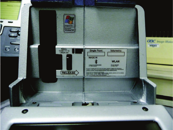
Regulatory Information
Regulatory information for the wireless components of the EDGE is
listed on the back of the base. Open the fold-down touch screen
controller to see this label.
Bluetooth
FCC ID: ED9LMX9838
IC: 1520A-LMX9838
DECLARATION OF CONFORMITY
FCC Compliance Statement:
This device complies with Part 15 of the FCC rules. Operation is subject
to the following two conditions:
1 This Device may not cause harmful interference, and
2 This device must accept any interference received, including
interference that may cause undesired operation.
Information To The User:
This equipment has been tested and found to comply with the limits for
a Class B digital device, pursuant to Part 15 of the FCC Rules. These
08M52E00_FaroArm_EDGE.book Page 4 Friday, October 1, 2010 11:14 AM
FaroArm®EDGE™ Manual
September 2010 - DRAFT
5
Chapter 1: Introduction
limits are designed to provide reasonable protection against harmful
interference in a residential installation. This equipment generates, uses,
and can radiate radio frequency energy and, if not installed and used in
accordance with the instructions, may cause harmful interference to
radio communications. However, there is no guarantee that interference
will not occur in a particular installation.
If this equipment does cause harmful interference to radio or television
reception, which can be determined by turning the equipment off and on
the user is encouraged to try to correct the interference by one or more
of the following measures:
• Reorient or relocate the receiving antenna.
• Increase the separation between the equipment and receiver.
• Connect the equipment into an outlet on a circuit different from that
to which the receiver is connected.
• Consult the dealer or an experienced radio/television technician for
help.
CAUTION: Any change or modification not expressly approved by
FARO Technologies, Inc. may void the user's authority to operate the
equipment.
NOTE: Bluetooth can be used concurrently with the USB Device and/or
Ethernet ports but not the WLAN (802.11g) port. The WLAN
(802.11b/g) interface is disabled by hardware and firmware.
DECLARATION OF CONFORMITY
Industry Canada Statement
This device complies with RSS-210 of Industry Canada.
Operation is subject to the following two conditions:
1 This device may not cause interference, and
2 this device must accept any interference, including interference that
may cause undesired operation of the device.
CAUTION: EXPOSURE TO RADIO FREQUENCY RADIATION
The installer of this radio equipment must ensure that the antenna is
located or pointed such that it does not emit RF field in excess of Health
Canada limits for the general population: consult Safety Code 6,
obtainable from Health Canada's website www.hc-sc.gc.ca/rpb
08M52E00_FaroArm_EDGE.book Page 5 Friday, October 1, 2010 11:14 AM
Wireless Local Area Network (WLAN 802.11)
FCC ID: YQM14000
IC: 9265A-14000
DECLARATION OF CONFORMITY
FCC Compliance Statement:
This device complies with Part 15 of the FCC rules. Operation is subject
to the following two conditions:
1 This Device may not cause harmful interference, and
2 This device must accept any interference received, including
interference that may cause undesired operation.
Information To The User:
This equipment has been tested and found to comply with the limits for
a Class B digital device, pursuant to Part 15 of the FCC Rules. These
limits are designed to provide reasonable protection against harmful
interference in a residential installation. This equipment generates, uses,
and can radiate radio frequency energy and, if not installed and used in
accordance with the instructions, may cause harmful interference to
radio communications. However, there is no guarantee that interference
will not occur in a particular installation.
If this equipment does cause harmful interference to radio or television
reception, which can be determined by turning the equipment off and on
the user is encouraged to try to correct the interference by one or more
of the following measures:
• Reorient or relocate the receiving antenna.
• Increase the separation between the equipment and receiver.
• Connect the equipment into an outlet on a circuit different from that
to which the receiver is connected.
• Consult the dealer or an experienced radio/television technician for
help.
CAUTION: Any change or modification not expressly approved by
FARO Technologies, Inc. may void the user's authority to operate the
equipment.
NOTE: The WLAN (802.11b/g) can be used concurrently with the USB
Device but not the LAN (Ethernet) or Bluetooth ports. The Bluetooth
interface is disabled by hardware and firmware.
08M52E00_FaroArm_EDGE.book Page 6 Friday, October 1, 2010 11:14 AM
FaroArm®EDGE™ Manual
September 2010 - DRAFT
7
Chapter 1: Introduction
DECLARATION OF CONFORMITY
Industry Canada Statement
This device complies with RSS-210 of Industry Canada.
Operation is subject to the following two conditions:
1 This device may not cause interference, and
2 this device must accept any interference, including interference that
may cause undesired operation of the device.
CAUTION: EXPOSURE TO RADIO FREQUENCY RADIATION
The installer of this radio equipment must ensure that the antenna is
located or pointed such that it does not emit RF field in excess of Health
Canada limits for the general population: consult Safety Code 6,
obtainable from Health Canada's website www.hc-sc.gc.ca/rpb
Product Environmental Information
Legislation is now in place within the European Union (EU) that
regulates waste from electrical and electronic equipment (WEEE).
European Directive 2002/96/EC on Waste Electrical and Electronic
Equipment (the WEEE Directive) stipulates that WEEE is now subject
to regulations designed to prevent the disposal of such waste and to
encourage design and treatment measures to minimize the amount of
waste that is placed into the waste stream. The objective of the WEEE
Directive is to preserve, protect and improve the quality of the
environment, protect human health, and stimulate the practical use of
natural resources. Specifically, the WEEE Directive requires that
producers of electrical and electronic equipment be responsible for the
collection, reuse, recycling and treatment of WEEE which the Producer
places on the EU market after August 13, 2005.
FARO Technologies, Inc., as a producer of electrical and electronic
equipment (EEE), has endeavored to meet these environmental
responsibilities for managing WEEE. In so doing, FARO is providing
the following to inform its customers about the WEEE collection
process:
In order to avoid any potential dissemination of hazardous substances
into the environment, FARO has labeled this product with the WEEE
symbol (see below) in order to alert the end-user that it should be
disposed of within the proper waste management system. That system
will recycle, reuse, and dispose of materials from this product in an
environmentally sound way.
08M52E00_FaroArm_EDGE.book Page 7 Friday, October 1, 2010 11:14 AM
FaroArm®EDGE™ Manual
September 2010 - DRAFT
8
Chapter 1: Introduction
The symbol represented below, and found on this FARO Technologies
product, indicates that this product meets the European Directive 2002/
96/EC on Waste Electrical and Electronic Equipment. This symbol, only
applicable in European Union countries, indicates that when this
product reaches the end of its useful life it should not be disposed of
with normal household or municipal waste, but in an established waste
stream for WEEE.
Each EU Member State country has established a system for the
collection, disposal, and recycling of WEEE. End-users in the EU
should contact their local waste administration system for collection
instructions concerning this product.
Refer to www.faro.com for further environmental information
concerning this product.
Precautions
The EDGE is a precision measuring device that is ruggedized for shop
use; however, care must still be exercised in the operating environment
when using the EDGE. Proper operation and care includes avoiding:
• Solvents.
• Abuse, such as dropping or twisting at end stops.
• Moisture and high humidity.
• Power fluctuations. See “EDGE Power Supply” on page 14.
• Excessive temperature changes without appropriate elapsed time.
See “Temperature Considerations” on page 75.
You r FaroA rm®EDGE™ can give you many years of service when you
treat it with care.
WEEE Symbol
08M52E00_FaroArm_EDGE.book Page 8 Friday, October 1, 2010 11:14 AM
FaroArm®EDGE™ Manual
September 2010 - DRAFT
9
Chapter 2: Setup
Chapter 2: Setup
The EDGE Packing Contents
The following components and accessories are standard items shipped
with every system:
EDGE - Packing List
• Shipping Case
• EDGE
• EDGE Assembly Instructions
• EDGE Manual (this book)
•FaroArm
® Accessories Manual
• EDGE Certification Documents
• Dust Cover
• Power Supply with electrical cable
• 7-Axis Handle
•Probe Case:
•Two probes
• Renishaw Adapter (i-Probe case only)
• FARO Calibration Cone
• FARO Calibration Sphere (i-Probe case only)
• 12mm wrench
• FARO probe torque wrench (i-Probe case only)
• USB cable
• Lithium Ion Smart Battery Pack
• Surface Mount Plate
NOTE: There are two different Probe Case options: Standard Probe
Case, and i-Probe Case.
Optional Accessories
The Accessories Manual that comes with your EDGE lists all of the
optional accessories that you can order from FARO. Installation and
detailed operational instructions are included.
The Accessories Manual is also available on FARO’s Web site at
www.faro.com. To purchase optional accessories, contact FARO’s
08M52E00_FaroArm_EDGE.book Page 9 Friday, October 1, 2010 11:14 AM
FaroArm®EDGE™ Manual
September 2010 - DRAFT
10
Chapter 2: Setup
Customer Service by Phone, Fax or E-Mail. See “Technical Support”
on page 43.
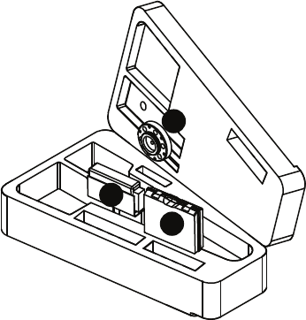
Packing the EDGE
The EDGE should be packed very carefully to prevent shipping
damage.
1 Pack the !Power Supply, "Probe Case, and #Surface Mount
Plate as shown.
NOTE: Remove the 7-Axis Handle from the EDGE before packing.
See “7-Axis Handle” on page 14.
2 Grasp the EDGE with both hands as shown.
Figure 2-1 Pack the Power Module, Probe Case, and Surface Mount Plate
1
2
3
08M52E00_FaroArm_EDGE.book Page 10 Friday, October 1, 2010 11:14 AM

FaroArm®EDGE™ Manual
September 2010 - DRAFT
11
Chapter 2: Setup
3 Insert the EDGE into the case.
Hardware Setup
The following sections describe the proper setup of the EDGE system.
This includes attaching the EDGE to your work surface and connecting
the EDGE to your computer.
Mounting the Base
The counterbalance by the tension spring generates torque at the base of
the EDGE; therefore, the mount must meet certain requirements to
achieve optimum machine accuracy.
NOTE: The EDGE must be mounted in a upright position. Do Not
mount the EDGE in an inverted (upside down) or sideways position.
To mount the EDGE:
1 Attach the 3.5" threaded ring and surface mount plate to any stable
location. Tighten all mounting bolts to 100-inch pounds.
2 Place the EDGE on top of the 3.5” threaded ring.
3 Fold out the collar clamp handles and screw the threaded collar clamp
onto the 3.5” threaded ring.
Figure 2-2 Insert the EDGE into the Case
08M52E00_FaroArm_EDGE.book Page 11 Friday, October 1, 2010 11:14 AM
FaroArm®EDGE™ Manual
September 2010 - DRAFT
12
Chapter 2: Setup
4 Use the collar clamp handles to tighten the threaded collar clamp.
For more information see “Mounting Stiffness Test” on page 74 and
“EDGE/ScanArm Performance Verification Checklist” on page 87.
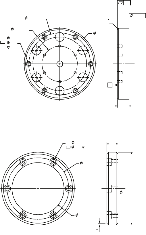
Surface Mount Plate Dimensions
The Surface Mount Plate is used to clamp or bolt the EDGE to a stable
mounting surface. It is an assembly of a standard 3½” mounting ring
and a FARO designed base plate.
Figure 2-3 Mounting the EDGE
08M52E00_FaroArm_EDGE.book Page 12 Friday, October 1, 2010 11:14 AM
FaroArm®EDGE™ Manual
September 2010 - DRAFT
13
Chapter 2: Setup
You can bolt the Surface Mount Plate directly to a surface using the
mounting screws in the Probe Case. Make sure to tighten each mounting
screw with the hex wrench.
You can bolt the 3½” mounting ring directly to a surface using the
mounting screws in the Probe Case. Make sure to tighten each mounting
screw with the hex wrench.
Figure 2-4 Surface Mount Plate dimensions
Figure 2-5 Standard 3½” Mounting Ring dimensions
5.950
BC2.970
.406
.38
BC5.187
6X .281
A
CHAMFER
.12 X 45
.001
.001
A
1.00
EQUALLY SPACED
WITHIN .005
3.500-8 UNC-2A
2X .09 X 45
CHAMFER
.54
2.50
2.970
.344 .22
6X .218
08M52E00_FaroArm_EDGE.book Page 13 Friday, October 1, 2010 11:14 AM

FaroArm®EDGE™ Manual
September 2010 - DRAFT
14
Chapter 2: Setup
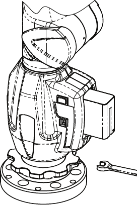
7-Axis Handle
You can attach a pistol-grip handle to the end of the EDGE to give you
another control option. The 7-Axis handle can be attached/detached
while the EDGE is powered On. To attach the handle:
1 Loosen the locking ring by turning it counterclockwise.
2 Insert the front edge of the 7-Axis handle into the slot.
3 Push the 7-Axis handle in so that the connectors connect.
4 Tighten the locking ring by turning it clockwise. Do not over
tighten the ring.
NOTE: Remove the 7-Axis Handle from the EDGE before packing.
See “Packing the EDGE” on page 10.
The FARO Laser Line Probe attaches in the same method. See “FARO
Laser Line Probe” on page 40.
EDGE Power Supply
Power the EDGE with the supplied power supply. The power supply is
NRTL Listed for US and Canada. For IEC member countries and
Europe, the power supply must be certified for the country in which the
equipment is sold. Contact FARO’s Customer Service to order a
replacement. All servicing should be referred to qualified service
personnel.
CAUTION (INDOOR USE ONLY)
Supplying Power to the EDGE
Place the EDGE in an area with a properly grounded outlet receptacle.
The On/Off switch is located on the back side of the base. Ensure the
Rated Voltage: 100 - 240V ~ 47 - 63 Hz
Voltage Tolerance: +10% or -10%
Rated Input: 1.4A
Sec. Voltage: +18 VDC
Sec. Current: 3.6A
Pollution Category: 2
Installation Category: 2
08M52E00_FaroArm_EDGE.book Page 14 Friday, October 1, 2010 11:14 AM
FaroArm®EDGE™ Manual
September 2010 - DRAFT
15
Chapter 2: Setup
On/Off switch is in the OFF position before supplying power.Connect
the Power Supply cord to the port on the back side of the base.
WARNING: Do not disconnect or isolate the ground pin on the power
supply cord.
Select the proper power supply cord intended for installation in a
protected environment. The power supply automatically adjusts to the
voltage.
• For 120V Connection: Use a UL Listed, type SJT or SVT, 3-
Conductor, 18 A.W.G. power supply cord, terminating in a molded-on
plug cap rated 125 VAC, 15A minimum, with a minimum length of
six feet.
• For 220 - 240V Connection: Use an international harmonized, 300V
rated, PVC insulated jacket, three conductors of 0.75mm2 minimum
cross-sectional area, each with a molded-on plug cap marked with
proper agency marking for the country where it will be used.
NOTE: Power surges, spikes, feedback, and fluctuation in the power
source will affect the equipment and its electronic accessories. Please
have your power source inspected by a professional to provide the
cleanest power source possible.
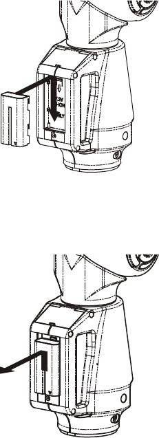
EDGE Battery Pack
Your EDGE may be powered using the supplied battery pack. Install the
battery pack to power your EDGE when you are not near a grounded
power outlet. On the front side of the base, open the fold-down touch
screen controller to access the battery pack slot.
NOTE: It is not necessary to install the battery pack if the EDGE is
connected to a power outlet.
Figure 2-6 Mounting the EDGE
USB
PORT
On/Off
SWITCH
08M52E00_FaroArm_EDGE.book Page 15 Friday, October 1, 2010 11:14 AM
FaroArm®EDGE™ Manual
September 2010 - DRAFT
16
Chapter 2: Setup
Installing the Battery Pack
Slide the battery pack with the rounded side down.
Removing the Battery Pack
Push the battery release lever to the right and pull out the battery pack.
Charging the Battery Pack
Install the battery pack and connect the EDGE to a power outlet and the
battery will begin to charge. The battery will charge if the On/Off switch
is set to the OFF position. Charging automatically stops when the
battery pack is completely charged. The DIAGNOSTICS dialog box
displays the current status of the battery pack. See “Diagnostics” on
page 96. The battery pack also has a built-in charge meter. Press the soft
button near the connector and look at the LEDs to see the current
charge.
Figure 2-7 Installing the battery
Figure 2-8 Removing the battery
08M52E00_FaroArm_EDGE.book Page 16 Friday, October 1, 2010 11:14 AM
FaroArm®EDGE™ Manual
September 2010 - DRAFT
17
Chapter 2: Setup
WARNING: Only use the rechargeable battery pack supplied with
your EDGE. For information on ordering additional or replacement
battery packs, contact FARO’s Customer Service by Phone, Fax or E-
Mail. See “Technical Support” on page 43.
Fold-Down Touch Screen Controller
Located on the front side of the EDGE base is a touch screen controller.
The controller is built into a panel that folds-down from the top of the
base. Press the locking latch at the top of the base to open the panel, and
access the touch screen controller.
Host Computer
The EDGE output is accepted through any PC-compatible computer
using the following communication protocols:
• USB 2.0 (Device)
• Ethernet (802.3)
• Bluetooth
• Wireless Local Area Network (WLAN 802.11)
You can use multiple communication protocols with the following
limitations:
• USB, Ethernet, and Bluetooth are active at the same time, WLAN is
disabled
• USB and WLAN are active at the same time, Bluetooth is disabled.
• WLAN is disabled if Ethernet is active
• WLAN is disabled if Bluetooth is active
Wired connections
USB communication connects from the EDGE to the computer using a
standard USB cable. High speed operation is supported.
Ethernet communication connects from the EDGE to the computer
using a regular or crossover twisted-pair Ethernet cable (Cat 5, Cat5e or
08M52E00_FaroArm_EDGE.book Page 17 Friday, October 1, 2010 11:14 AM
FaroArm®EDGE™ Manual
September 2010 - DRAFT
18
Chapter 2: Setup
Cat 6) with RJ-45 connectors. When Ethernet is used the EDGE is
configured as a DHCP Client.
The USB and Ethernet connectors are located on the back side of the
base.
NOTE: In a multiple computer networking environment, you should
consult your Information Technology (IT) department for assistance
with installing the EDGE.
CAUTION: Complete all cable connections before applying power
to the computer and the EDGE.
NOTE: For optimum performance, allow the EDGE to warm-up for at
least 30 minutes before using.
Ethernet
1 From the MAIN screen, choose CONNECTION.
2 Select the ETHERNET icon.
3 Select ENABLE TCP/IP.
4 Select EHTERNET in the DHCP column.
Wireless Connections
The EDGE is equipped to connect to your computer using different
wireless connections.
Figure 2-9 EDGE wired communication ports
USB
PORT
On/Off
SWITCH
08M52E00_FaroArm_EDGE.book Page 18 Friday, October 1, 2010 11:14 AM
FaroArm®EDGE™ Manual
September 2010 - DRAFT
19
Chapter 2: Setup
FARO Wireless - Bluetooth
The EDGE is a Bluetooth® equipped device and can connect to your
computer without using a cable.
Bluetooth wireless is a short-range communications technology
intended to replace the cables connecting devices. The range of a Class
2 system, such as the EDGE, is approximately 30 feet or 10 meters.
Bluetooth devices are generally paired, or associated with each other,
either openly or employing security, with one serving as the master
device and the second as the slave. In the case of the EDGE:
• The EDGE is the slave.
• The host computer is the master.
• Basic PIN based security is employed.
• The host computer establishes an RS-232 emulation or Serial Port
Profile (SPP) connection to the EDGE.
• Once the connection is established the PC and EDGE can transfer
data at a rate of 921600bits/second.
NOTE: If a EDGE is connected with USB cable and Bluetooth, only
the Bluetooth connection will be active.
EDGE to the Computer Connection
Create the wireless connection between the host computer and the
EDGE created using:
• Software supplied with a Bluetooth equipped computer, or an
aftermarket USB Bluetooth dongle and software.
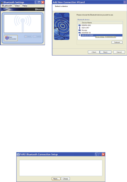
• FARO Bluetooth Connection Setup utility software.
NOTE: Implementation will differ among software suppliers, but
generally there is a platform specific Bluetooth Wizard that will
08M52E00_FaroArm_EDGE.book Page 19 Friday, October 1, 2010 11:14 AM
FaroArm®EDGE™ Manual
September 2010 - DRAFT
20
Chapter 2: Setup
search for all Bluetooth devices in range and display them
graphically, or in a simple list.
All EDGEs are identified by their serial number. Once a EDGE is
identified in the list, a persistent SPP connection must be created. Once
the connection exists, the software will display the connection’s COM
port number, for example COM10.
Write down your SPP connection COM port
______________________
This number is important and will be used later.
NOTE: If the platform specific Bluetooth Wizard finds two COM
ports, usually labeled “Incoming” and “Outgoing,” for the EDGE, use
the Outgoing COM port.
Computer to the EDGE Driver Connection
The EDGE USB driver connects to the SPP connection using the FARO
Bluetooth Connection Setup utility software.
• Start FARO Bluetooth Connection Setup utility software program.
Figure 2-10 Connecting the EDGE to the Computer
Figure 2-11 Connecting the EDGE to the Computer
08M52E00_FaroArm_EDGE.book Page 20 Friday, October 1, 2010 11:14 AM
FaroArm®EDGE™ Manual
September 2010 - DRAFT
21
Chapter 2: Setup
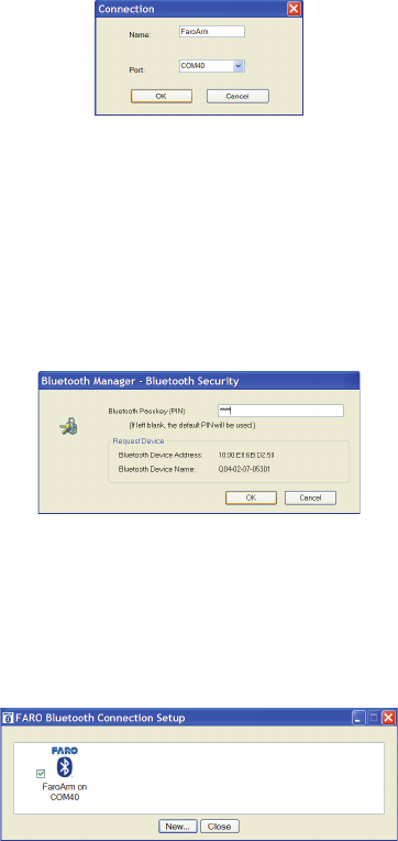
• Click the NEW button.
• Type a name for your connection
•In the P
ORT list select the proper COM from the platform specific
Bluetooth Wizard (e.g. COM10). This is the port that you previously
wrote down.
• Click the OK button.
A test is automatically run to verify that the COM port is connected to
the EDGE.
• Enter the EDGE PIN security code, faro.
• Click OK to save the connection.
An icon will be created for each Bluetooth pairing. The icon with the
check box selected is an active connection. The icon without a check
box selected is an inactive connection.
NOTE: No more than two (2) EDGE pairings can be active at any one
time, but any number can be defined.
Editing a Pairing
Right-click any Bluetooth pairing icon to edit. You can:
• Edit the name and the COM port.
Figure 2-12 Connection Name and COM port
Figure 2-13 EDGE Bluetooth PIN
Figure 2-14 Connecting the EDGE to the Computer
08M52E00_FaroArm_EDGE.book Page 21 Friday, October 1, 2010 11:14 AM
FaroArm®EDGE™ Manual
September 2010 - DRAFT
22
Chapter 2: Setup
• Test the pairing connection.
• Delete the pairing.
Using the EDGE Bluetooth Pairing
When the measuring software is launched (CAM2 Q, CAM2 Measure,
CAM2 Measure X, Geomagic, Polyworks, etc.) the EDGE driver
attempts to use any EDGE connection - USB cable and any active
Bluetooth pairings. It takes slightly longer, 8 or 10 seconds, for a EDGE
to connect and initialize via Bluetooth.
NOTE: If you choose not to connect the EDGE to your computer
using the wireless connection, deselect the icon check box in the
FARO Bluetooth Connection Setup utility to deactivate the pairing
and connect using the USB cable.
Once you start measuring, there is no difference in data transfer between
using the Bluetooth connection or the USB cable.
FARO Wireless - WLAN
The EDGE is a Wireless Local Area Network (WLAN) equipped device
and can connect to your computer without using a cable.
A WLAN is a series of interconnected computers that communicate
with each other over the air waves rather than through a network cable
connected to each computer. In a WLAN, a radio communications
device called an access point, or wireless router, connects network
computers and provides network access. The access point, or wireless
router, and the wireless network card in the computer communicate by
broadcasting data from their antennas over the air waves.
The EDGE WLAN is normally configured as a DHCP Client. Due to
the nature of an open air system network security is very important.
Before discussing EDGE WLAN setup a brief WLAN Primer is
presented.
WLAN Primer
An EDGE node or station can connect to a WLAN that complies
with the IEEE 802.11g standard. The Wi-Fi Alliance (an industry
group promoting 802.11 networks) has popularized the term Wi-
Fi® for 802.11 compliant networks. The term WLAN, refers to the
slightly more generalized concept of the wireless extension of a
local area network (LAN), though in practice most implementations
use Wi-Fi technology.
08M52E00_FaroArm_EDGE.book Page 22 Friday, October 1, 2010 11:14 AM
FaroArm®EDGE™ Manual
September 2010 - DRAFT
23
Chapter 2: Setup
The IEEE 802.11 standard specifies a Medium Access Control
(MAC) and physical layers (PHY) for wireless connectivity
between stations (STAs). A set of stations that have joined the same
network have access to the same network services. These services
are called a Basic Service Set (BSS). Every BSS has a unique 48-bit
identifier called the Basic Service Set Identifier (BSSID). The
standard specifies two types of BSS, and Independent BSS (IBSS)
and an Infrastructure BSS (BSS).
There are several different PHY layers specified in IEEE 802.11.
The Edge uses 802.11g.
IEEE 802.11 further breaks up the 2.4 GHz frequency band into 14
overlapping channels. Each country in the world has its own rules
and regulations regarding radio usage. Many countries join together
to coordinate these regulations, forming “Regulatory Domains”.
Most European, Middle East. North and South American, African
countries and Australia and Japan use the same regulations.
However, there are differences with regard to which channels and
power levels are permitted. The EDGE can support all 14 channels
- factory programming is performed for the specific country the
EDGE is to be used (this is not a user option).
Independent BSS (IBSS)
An IBSS is used to form an Ad Hoc network between peer STAs.
STAs share responsibility for maintaining the IBSS and distributing
data to each other. IBSS is NOT supported for the EDGE WLAN.
Infrastructure BSS (BSS)
In an Infrastructure BSS there is one special STA called the Access
Point (AP). The AP is solely responsible for starting and
maintaining the BSS and admitting (or excluding) other STAs. The
AP receives all traffic either bound for or originating from every
STA that it admits into its BSS. (Exception is contained in IEEE
802.11e amendment for Quality of Service - a special QoS BSS).
The STAs are known as Clients, the AP is known as a Server.
A Distribution System (DS) interconnects a set of AP's to create an
Extended Service Set (ESS). The ESS is a super set of all member
STAs. The DS distributes data between ESS STAs. An ESS may
include LANs (via a gateway).
The simplest and most common configuration is to have an ESS
that includes exactly one AP. It is known as a Small Or Home
08M52E00_FaroArm_EDGE.book Page 23 Friday, October 1, 2010 11:14 AM
FaroArm®EDGE™ Manual
September 2010 - DRAFT
24
Chapter 2: Setup
Office (SOHO). This is the intended configuration for the Edge
ARM Stations.
In an Infrastructure BSS, the AP broadcasts Beacon frames that
announce the identity and capabilities of its BSS.
Joining a WLAN
An STA joins a WLAN using a three-step process:
1 Scanning
2 Association
3 Authentication
Scanning
STA generates a list of all BSSs (APs in the network) it can detect.
Association
In an Infrastructure BSS the Association process requires a frame
exchange between the joining STA and the selected AP. This frame
includes the STAs capabilities. The AP will accept or deny the
request (Association Response Frame). The STA (Client) learns the
BSSID (SSID - Service Set Identifier or WLAN name) and AP MAC
address. If the STA is accepted the AP will issue an Association
Identifier (AID - logical port) at this time.
Authentication
Apply Security - establish a secure wireless network. WPA2-Personal
is recommended for the FARO WLAN security (based on IEEE
802.11i and Advanced Encryption Standard -AES). The password is
the real key to security!
Establishing a FARO WLAN Connection
There are a minimum of three stations to be configured. This may be
performed in any order but the typical order is:
1 Setup Access Point
2 Setup EDGE
3 Setup Host Computer
Access Point (AP)
Normally the Access Point is configured first. This setup may have
been done by the your companies IT department. If this is the case, IT
should provide the Network Name (SSID) and Password.
All Clients must use the same SSID and Password as the AP.
The recommended security setting is either WPA-PSK (TKIP
encryption algorithm) {Good} or WPA2-PSK (AES-CCMP
08M52E00_FaroArm_EDGE.book Page 24 Friday, October 1, 2010 11:14 AM
FaroArm®EDGE™ Manual
September 2010 - DRAFT
25
Chapter 2: Setup
encryption algorithm) {Better, if available}. You should use a
Password of 10 or more random alphanumeric characters.
NOTE: Wi-Fi Protected Access (WPA).
The EDGE User Console - WLAN Client Setup Sequence
The Access Point should be configured and running.
1 From the MAIN screen, choose CONNECTION.
2 Select the Wi-Fi icon.
3 Select Enable TCP/IP.
4 Select DHCP WiFi to Network in the DHCP column.
NOTE: Only expert users should the Static IP option.
5 Click the NEXT arrow icon in the lower right corner of the screen.
The next screen is a list of active APs.
6 Select an active AP.
7 Click the NEXT arrow icon in the lower right corner of the screen.
The next screen is WiFi security. Enter the exact settings for the AP.
NOTE: The Password is case sensitive.
The Host Computer Setup
The Access Point should be configured and running.
The ease of configuring client stations depends principally on the
configuration utility used. Windows XP comes with its own
configuration utility built in, Windows Zero Configuration Utility
(WZC). However, there are other configuration utilities that offer
better efficiency, easier configuration, and better wireless monitoring.
Most client cards come with their own wireless configuration utility,
though others depend on Windows. Here we'll describe the
configuration of client stations using WZC, which is the lowest
common denominator for most users.
1 Add preferred network - Enter SSID (example here is “My
Network SSID”).
2 Configure Client to the same settings as the AP. To do so, click on
the PROPERTIES button. The SECURITY PROPERTIES dialog box
appears. The first text box will already be filled in with the SSID
selected for the preferred network name.
3In the N
ETWORK AUTHENTICATION drop-down window, select
WPA-PSK.
08M52E00_FaroArm_EDGE.book Page 25 Friday, October 1, 2010 11:14 AM
FaroArm®EDGE™ Manual
September 2010 - DRAFT
26
Chapter 2: Setup
4In the DATA ENCRYPTION drop-down window, select TKIP.
5 The last step is most important - the Network Key entered and
confirmed must be the same as the network key (password) that
was entered on the AP.
NOTE: Network keys are case sensitive.
Wireless Zero Configuration Reference
The Wireless Zero Configuration programming interface is no longer
supported as of Windows Vista and Windows Server 2008. Instead, use
the Native Wifi API, which provides similar functionality. For more
information, see About the Native Wifi API on the Microsoft web site.
http://msdn.microsoft.com/en-us/library/ms705969(v=VS.85).aspx
This section contains information on the programming interface for the
Wireless Zero Configuration service on Windows XP. The topics
include:
•Wireless Zero Configuration Functions
http://msdn.microsoft.com/en-us/library/ms706587(v=VS.85).aspx
•Wireless Zero Configuration Structures
http://msdn.microsoft.com/en-us/library/ms706600(v=VS.85).aspx
Wireless Zero Configuration is a Windows service on Windows XP that
is used to configure and manage wireless network connections on a
wireless adapter. The Wireless Zero Configuration service is normally
started at boot time. The programming interface for the Wireless Zero
Configuration service can be used only if the Wireless Zero
Configuration service has been started. If the Wireless Zero
Configuration service is not started, then the Wireless Zero
Configuration functions will return an error.
To enable the Wireless Zero Configuration service so it starts up
automatically:
• Select the START button
• Select the SETTINGS option and then select CONTROL PANEL
• If you are using the Windows XP view, select the
PERFORMANCE AND MAINTENANCE category and then
select ADMINISTRATIVE TOOLS.
• If you are using the Classic View, then select ADMINISTRATIVE
TOOLS.
• Click the SERVICES icon in the left pane.
08M52E00_FaroArm_EDGE.book Page 26 Friday, October 1, 2010 11:14 AM
FaroArm®EDGE™ Manual
September 2010 - DRAFT
27
Chapter 2: Setup
• Click the WIRELESS ZERO CONFIGURATION icon in the right pane and
change the Startup Type drop-down window to AUTOMATIC. This
setting will set the service to start automatically at boot time.
• Click the START button to start the Wireless Zero Wireless Zero
Configuration service and click the OK button.
The Wireless Zero Configuration can also be started and stopped from a
command prompt. To start the Wireless Zero Configuration, run the
following command:
net start wzcsvc
To stop the Wireless Zero Configuration, run the following command:
net stop wzcsvc
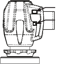
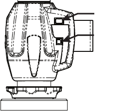
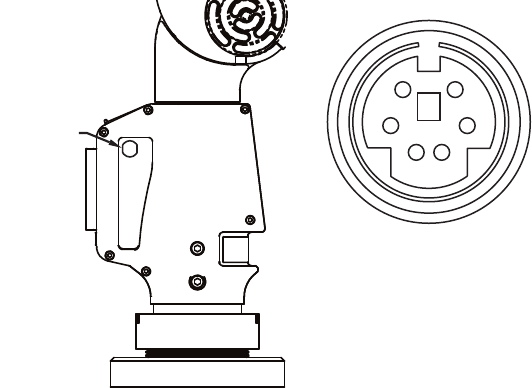
Auxiliary Port (7th Variable Options Port)
On the front side of the EDGE base, an optional communications port is
available to connect external equipment. To get a list of approved FARO
devices, contact your Customer Service Representative by Phone, Fax
or E-Mail. See “Technical Support” on page 43.
WARNING: Only use FARO approved devices in this port. For
more information about approved FARO devices, contact FARO’s
Customer Service. Using other devices could damage your system
and will void your maintenance/warranty service plan.
Figure 2-15 Auxiliary Port
AUXILIARY
PORT
12
34
56
08M52E00_FaroArm_EDGE.book Page 27 Friday, October 1, 2010 11:14 AM
FaroArm®EDGE™ Manual
September 2010 - DRAFT
28
Chapter 2: Setup
08M52E00_FaroArm_EDGE.book Page 28 Friday, October 1, 2010 11:14 AM
FaroArm®EDGE™ Manual
September 2010 - DRAFT
29
Chapter 3: Operation
Chapter 3: Operation
Numerical and Signal Processing
The EDGE includes a complete electronics system located within the
body of the EDGE. Signals from each joint are processed and positional
data is sent out to the computer.
NOTE: The EDGE electronics go into standby mode, or turn off, after
two hours of no encoder movement. Move the EDGE to exit standby
mode and reference the encoders to continue measuring. See
“Referencing the Encoders” on page 31.
Handle LED
After applying power to the EDGE, the
LED is SOLID GREEN while an internal
startup check runs. After this is complete,
the LED indicates the following:
• FLASHING RED - if the EDGE
successfully communicates with the
computer, and the encoders are not
referenced. See “Referencing the
Encoders” on page 31.
• OFF - if the EDGE successfully
communicates with the computer, and
the encoders are referenced. See
“Referencing the Encoders” on
page 31.
• SOLID GREEN - if the EDGE
successfully communicates with the
computer, and the encoders are
referenced - Renishaw Probe only. See
“Renishaw TP-20 Probe Installation
and Operation” on page 37.
LED
BACK BUTTON
FRONT BUTTON
BACK BUTTON
FRONT BUTTON
LED
08M52E00_FaroArm_EDGE.book Page 29 Friday, October 1, 2010 11:14 AM

FaroArm®EDGE™ Manual
September 2010 - DRAFT
30
Chapter 3: Operation
Error and Status Indicators
Through the driver interface to the measuring software, the EDGE
generates and displays errors in the END STOP/STRESS WARNING dialog
box.
• The encoder end stop warnings - This warning appears when an
encoder reaches one end of its rotation.
• The tube stress stop warnings - This warning appears when there is
stress on one of the tubes or encoder joints. The stress stop warnings
may be disabled. See “Hardware Configuration” on page 82.
Figure 3-1 EDGE end stop warning
Figure 3-2 EDGE stress stop warning
08M52E00_FaroArm_EDGE.book Page 30 Friday, October 1, 2010 11:14 AM
FaroArm®EDGE™ Manual
September 2010 - DRAFT
31
Chapter 3: Operation
• The unknown FARO i-Probe warning - This warning appears when a
FARO i-Probe is attached to the EDGE and never calibrated. For
accurate measuring, you must calibrate the probe. Use your measuring
software to setup and calibrate the probe. See “Probes” on page 83.
• The missing FARO i-Probe warning - This warning appears when no
probe is attached to the EDGE.
• Other errors appear in a message box.
NOTE: The EDGE does not output data until the error has been
cleared.
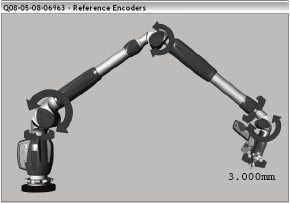
Referencing the Encoders
You must reference each of the six (or seven) encoders in the EDGE
before the system can output data. The REFERENCE ENCODERS dialog
box shows all six encoders in error until each is referenced. In a
Figure 3-3 Unknown FARO i-Probe warning
Figure 3-4 Unknown FARO i-Probe warning
08M52E00_FaroArm_EDGE.book Page 31 Friday, October 1, 2010 11:14 AM
FaroArm®EDGE™ Manual
September 2010 - DRAFT
32
Chapter 3: Operation
systematic manner, rotate joints 1 through 6 (7) until each warning
clears.
NOTE: The EDGE must be properly connected to the host computer
running the measuring software to see the REFERENCE ENCODERS
dialog box.
EDGE Handle Buttons
The EDGE has two sets of two buttons and an LED, where the FRONT
buttons and BACK buttons are redundant and wired together internally.
Figure 3-5 Referencing the encoders
08M52E00_FaroArm_EDGE.book Page 32 Friday, October 1, 2010 11:14 AM
FaroArm®EDGE™ Manual
September 2010 - DRAFT
33
Chapter 3: Operation
When a button is pressed, the LED light turns on (green or red) and the
Computer sounds. See “Handle LED” on page 29.
The FRONT button is used to collect data, and the BACK button to
accept the data.
• The FRONT button is green and nearest the probe.
• The BACK button is red and is nearest the handle.
Handle Storage
The EDGE has a magnetic attached to tube 2 for easy storage of the
Figure 3-6 EDGE Handle Buttons
LED
BACK BUTTON
FRONT BUTTON
BACK BUTTON
FRONT BUTTON
LED
08M52E00_FaroArm_EDGE.book Page 33 Friday, October 1, 2010 11:14 AM
FaroArm®EDGE™ Manual
September 2010 - DRAFT
34
Chapter 3: Operation
08M52E00_FaroArm_EDGE.book Page 34 Friday, October 1, 2010 11:14 AM
FaroArm®EDGE™ Manual
September 2010 - DRAFT
35
Chapter 4: Probes
Chapter 4: Probes
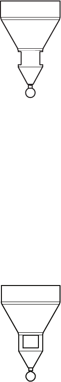
EDGE Probes
Two standard probes, one (1) 6mm Ball and one (1)
3mm Ball, are supplied with the EDGE. Each ball
probe is stamped with the exact diameter of the ball
(3.9997mm, 5.9994mm, etc.).
Start your measuring software (CAM2 Q, CAM2
Measure, CAM2 Measure X, Geomagic, Polyworks,
etc.) and edit the existing 3mm and 6mm probes. Enter
the exact diameter in the MODIFY PROBE dialog box for
each ball probe. See “Edit Probe” on page 84.
The EDGE’s point of measurement on any ball probe is the center of the
ball. Third-party feature measurement or quality control software
compensates for the radius of the ball probe. Point probes are only
recommended when the software will not compensate for the radius of
the ball probe. The point probe has an impact on measurement accuracy.
The error depends on:
• the width of the point on the probe
• the position and placement of the point on the object
NOTE: For accurate measuring, you must calibrate the probe. Use
your measuring software to setup and calibrate the probe. See
“Probes” on page 83.
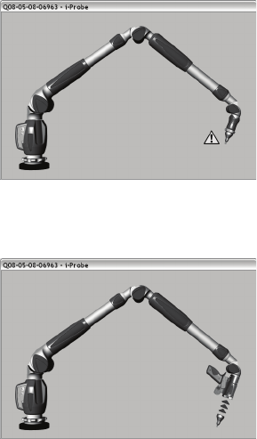
FARO i-Probe
The EDGE uses the optional FARO i-Probe. This is an
electronically serialized intelligent probe that
automatically provides its actual exact ball diameter to
the EDGE and monitors probe body temperature to
compensate for thermal deformation.
NOTE: FARO i-Probes will not attach to Platinum or
Fusion series FaroArms. Installing the i-Probe to
anything other than a Quantum series FaroArm
damages the i-Probe.
BALL SIZE:
5.9994mm
i-Probe
08M52E00_FaroArm_EDGE.book Page 35 Friday, October 1, 2010 11:14 AM

FaroArm®EDGE™ Manual
September 2010 - DRAFT
36
Chapter 4: Probes
Custom Probes
You can create any size probe to
attach to the EDGE.
• The EDGE Probe thread size is
1¼-20.
• The base of the probe should
follow the shape of the FARO
probes.
Your custom probe should be as
rigid as possible. Any deflection in
the probe will add inaccuracy to the
EDGE system.
NOTE: FARO Technologies Inc.
does not guarantee the accuracy
of the EDGE with the use of a custom probe.
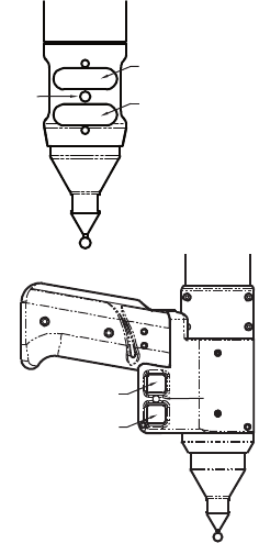
Installing Probes
The probe attaches to the threaded handle at the end of the EDGE. Use
the 12mm wrench in the Probe Case to install the probe.
NOTE: Use the FARO probe torque wrench to tighten the FARO i-
Probe. The probe wrench will break free when you apply the proper
amount of torque.
1¼-20 THD
11.85
R 0.5
19.5
ø
ø10
MAX
25.1
24.9
ø32.4
32.2
62˚
28˚
31.6
31.4
9.6
9.4
2.6
2.4
08M52E00_FaroArm_EDGE.book Page 36 Friday, October 1, 2010 11:14 AM
FaroArm®EDGE™ Manual
September 2010 - DRAFT
37
Chapter 4: Probes
• Hold the button area near the end of the EDGE with one hand.
CAUTION: Do not hold the EDGE except in the button area when
installing a probe. Holding the EDGE at the last joint may stress the
tube and damage the system.
• Rotate the probe clockwise and thread the probe into the EDGE.
• Use the 12mm wrench to hand-tighten the probe.
CAUTION: Only hand-tighten the probe with the 12mm wrench. Do
not over-tighten the probe.
Use your measuring software to setup and calibrate the probe. See
“Probes” on page 83.
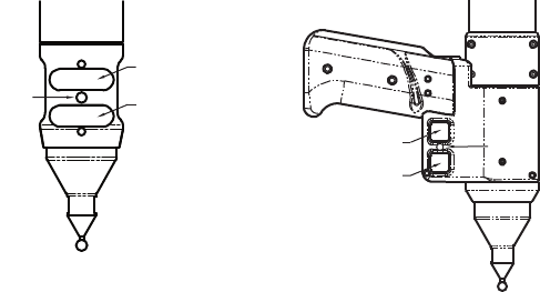
Renishaw TP-20 Probe Installation and
Operation
The EDGE supports the Renishaw TP-20 touch-trigger probe by using
the FARO i-Probe adapter to connect the TP-20 probe module to the
EDGE handle. Simply attach this assembly just as you would any other
probe. See “Installing Probes” on page 36.
The Renishaw TP-20 touch-trigger probe automatically digitizes a point
by touching the stylus to the part.
NOTE: The Renishaw TP-2 Probe is not supported.
Figure 4-1 Installing a Probe
08M52E00_FaroArm_EDGE.book Page 37 Friday, October 1, 2010 11:14 AM
FaroArm®EDGE™ Manual
September 2010 - DRAFT
38
Chapter 4: Probes
EDGE TP-20 Probe Kit
The EDGE TP-20 Probe kit contains:
• A magnetized TP-20 probe body
• Medium Force Probe Module
• Renishaw (S1) C Spanner wrench
• Renishaw (S7) stylus tool
• Renishaw (CK200) cleaning kit
• Renishaw Probe tip: 2mm (M2 D2R L10)
• Renishaw Probe tip: 6mm (M2 D6R L10)
• EDGE i-Probe adapter
NOTE: The product numbers in the parentheses are Renishaw part
numbers. See the Renishaw User’s Manual for more details.
To install the TP-20 Probe:
1 Remove the current probe.
2 Install the EDGE i-Probe adapter. Tighten using the 12mm torque
wrench.
Figure 4-2 Installing a Renishaw Probe
08M52E00_FaroArm_EDGE.book Page 38 Friday, October 1, 2010 11:14 AM
FaroArm®EDGE™ Manual
September 2010 - DRAFT
39
Chapter 4: Probes
3 Screw the TP-20 probe body into the EDGE i-Probe adapter and
hand-tighten with the C Spanner (S9) wrench.
4 Attach a probe module to the TP-20 probe body. On the probe body
and probe module are triangle, half-moon, and square markers that
must be aligned for the probe to work properly.
5 Screw the Renishaw Probe tip into the probe module with the stylus
tool (S7). Do not under- or over-tighten any of the components.
Probe Modules for the TP-20 Probe
Probe modules are available from Renishaw in three trigger force
ratings:
• Standard Force Probe Module (Black cap)
• Medium Force Probe Module (Gray cap)
• Extended Force Probe Module (Brown cap)
Refer to the Renishaw TP-20 Installation and User’s Manual for the
TP-20 Probe assembly instructions.
Measuring Software
The measuring software must be configured for the probe.
• In CAM2 Q, choose the DEVICES < DEVICE CONTROL command
and click the PROBE MANAGEMENT button. See “Change Probe” on
page 98.
• In CAM2 Measure choose the PROBES command. See “Probes” on
page 83.
• Create a new probe and switch the auxiliary port to the ON
position by placing a check mark in the Aux Switch check box.
See “Edit Probe” on page 84.
• Calibrate the probe using the FARO Calibration Sphere, or any
precision sphere, after installation. See “Sphere Method” on
page 91.
Some software packages have other probe options that must also be
controlled. See the Renishaw User’s Manual for more information.
The probe digitizes a point when it makes contact with an object. It may
digitize multiple points when bounced off an object. Watch the LED
light on the EDGE handle and listen to the sounds of the computer to
08M52E00_FaroArm_EDGE.book Page 39 Friday, October 1, 2010 11:14 AM
FaroArm®EDGE™ Manual
September 2010 - DRAFT
40
Chapter 4: Probes
ensure that only one point was digitized. The LED light turns off and the
computer sounds when a point is digitized.
Custom Probe Calibration
Any probe with a sphere or a point can be calibrated. See “Compensate
Probe” on page 86.
FARO Laser Line Probe
The FARO Laser Line Probe is a non-contact probe that collects
digitized points using a laser and a camera. The laser is projected onto
your part as a line, the camera takes a picture of the shape and position
of the line, and creates several points. These individual points are then
sent to the computer.
Laser Safety
The FARO Laser Line Probe outputs a visible red laser beam. Although
this is a CDRH Class II and IEC Class 2M power level, operation of the
device requires the operator to avoid direct exposure to eyes at all times.
You should avoid direct exposure to your eye at all times. Although the
human blink reaction to bright light provides a natural mechanism of
protection to this visible laser beam, use caution while handling the
FARO Laser Line Probe by pointing it at only the target object.
CAUTION: USE OF CONTROLS OR ADJUSTMENTS OR
PERFORMANCE OF PROCEDURES OTHER THAN THOSE
SPECIFIED HEREIN MAY RESULT IN HAZARDOUS LASER
LIGHT EXPOSURE.
08M52E00_FaroArm_EDGE.book Page 40 Friday, October 1, 2010 11:14 AM
FaroArm®EDGE™ Manual
September 2010 - DRAFT
41
Chapter 4: Probes
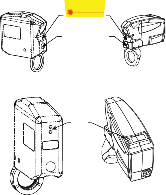
Laser Radiation Emission
When the FARO Laser Line Probe is operating, a laser beam emits from
the aperture at the front of the FARO Laser Line Probe. See Figure 4-3
for the location of the laser beam aperture.
When the laser is operating, the LEDs on the back of the unit illuminate.
See Figure 4-4 for the location of the laser emission indicator.
These LEDs also indicate the range of the laser to the target surface. For
more information, see “LEDs” on page 46.
CAUTION: VIEWING THE LASER OUTPUT WITH CERTAIN
OPTICAL INSTRUMENTS (EYE LOUPES, MAGNIFIERS, AND
MICROSCOPES, ETC.) WITHIN A DISTANCE OF 100 MM MAY
POSE AN EYE HAZARD.
Figure 4-3 Laser Aperture
Figure 4-4 Laser emission indicator
AVOID EXPOSURE
Visible and/or invisible
laser radiation is emitted
from this aperture
LASER APERTURE
LEDs
08M52E00_FaroArm_EDGE.book Page 41 Friday, October 1, 2010 11:14 AM
FaroArm®EDGE™ Manual
September 2010 - DRAFT
42
Chapter 4: Probes
Laser power up to 5 mW at 660 nm in a diverging beam could be
accessible in the interior of the FARO Laser Line Probe.
WARNING: DO NOT ATTEMPT TO OPEN THE FARO LASER
LINE PROBE CASE. THERE ARE NO USER SERVICEABLE
PARTS.
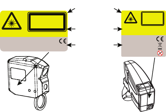
Serial Number Label
The FARO Laser Line Probe Serial Number label contains the serial
number, laser information, certification, warning logotype and
manufacturing date. See Figure 4-3 for the location of the laser beam
aperture.
Servicing
The FARO Laser Line Probe should only be serviced by FARO
Customer Support technicians. There are no user serviceable parts in
this device. DO NOT attempt to open the casing or disassemble the
device at any time.
If the FARO Laser Line Probe is not operating properly, contact FARO
Customer Support. If it has malfunctioned, power down the system,
remove it from the EDGE and return it to FARO Customer Support for
repair.
Figure 4-5 Serial Number label
655 nm Laser, 5 mW
LASER LIGHT
DO NOT STARE INTO BEAM
OR VIEW DIRECTLY WITH
OPTICAL INSTRUMENTS
CDRH CLASS II LASER PRODUCT, CONFORMS TO 21 CFR 1040
IEC CLASS 2M LASER PRODUCT, CONFORMS TO IEC/EN 60825-1/A2:2001
Serial Number:
Manufactured:
LLP000702881 Rev4.3
Aug 20, 2007
FARO Technologies, Inc. 125 Technology Park Lake Mary, FL 32746 U.S.A
LASER LIGHT
DO NOT STARE
INTO BEAM OR VIEW
DIRECTLY WITH
OPTICAL INSTRUMENTS
CDRH CLASS II LASER PRODUCT,
CONFORMS TO 21 CFR 1040
IEC CLASS 2M LASER PRODUCT,
CONFORMS TO IEC/EN 60825-1/A2:2001
655 nm Laser, 5 mW
Serial Number:
Manufactured:
FARO Technologies, Inc.
125 Technology Park • Lake Mary, FL 32746 • USA
LLP00074003 Rev1.0
Nov 17, 2007
WARNING
LOGOTYPE
CERTIFICATION
IDENTIFICATION
08M52E00_FaroArm_EDGE.book Page 42 Friday, October 1, 2010 11:14 AM
FaroArm®EDGE™ Manual
September 2010 - DRAFT
43
Chapter 4: Probes
WARNING: DO NOT ATTEMPT TO OPEN THE FARO LASER
LINE PROBE CASE. THERE ARE NO USER SERVICEABLE
PARTS.
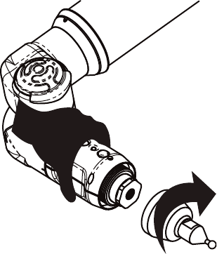
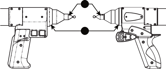
Hardware Installation
Installing the FARO Laser Line Probe is similar to any other EDGE
probe. However, there is a Trim Ring # on the end of the handle that
must be removed for the FARO Laser Line Probe to install correctly.
1 Turn Off the EDGE.
2 Remove any standard probe from the EDGE.
3 Remove the Trim ring from the EDGE handle.
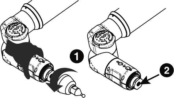
4 Attach the FARO Laser Line Probe by sliding it onto the top of the
EDGE handle. Slide the ring all the way to the back of the threaded
area, rotating the head slightly until the alignment pins seat into the
alignment slots.
5 Thread the locking collar into place and tighten with the 12mm
wrench from the EDGE Case. Do not over tighten the locking collar.
6 Install the 6mm or 3mm standard ball probe. See “Installing Probes”
on page 36.
Figure 4-6 Remove Probe and Trim Ring
2
3
08M52E00_FaroArm_EDGE.book Page 43 Friday, October 1, 2010 11:14 AM
FaroArm®EDGE™ Manual
September 2010 - DRAFT
44
Chapter 4: Probes
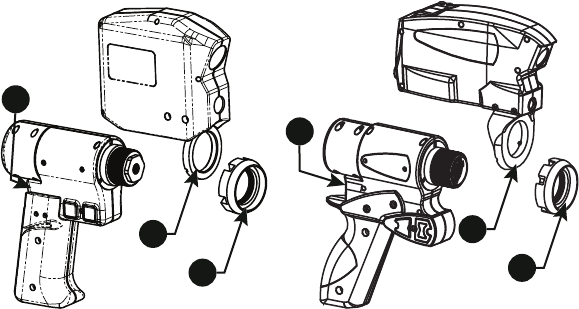
7 Connect the plug from the FARO Laser Line Probe to the options
port. The options port is located on the back of the EDGE handle.
Tighten the threaded connector.
CAUTION: Before inserting the connector, make sure that the power
is OFF.
• Clean the top and bottom lenses with the cloth from the FARO Laser
Line Probe Case. Dirt and grease on either lens can cause poor results.
• Connect the EDGE to the computer using the USB cable, and turn on
the computer.
• Connect the EDGE power supply and switch on the EDGE. This also
powers the FARO Laser Line Probe.
• Start the application software.
NOTE: Allow the FARO Laser Line Probe to warm-up:
• 60 minutes for version 1
• 30 minutes for version 2
• 15 minutes for version 3
Figure 4-7 Install the FARO Laser Line Probe
4
5
4
5
7
7
08M52E00_FaroArm_EDGE.book Page 44 Friday, October 1, 2010 11:14 AM
FaroArm®EDGE™ Manual
September 2010 - DRAFT
45
Chapter 4: Probes
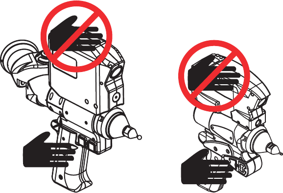
Holding the FARO Laser Line Probe
Never grab the FARO Laser Line Probe while measuring. Simply hold
the EDGE's pistol grip. Holding the FARO Laser Line Probe can cause
inaccuracy due to bending of its mounting bracket.
NOTE: Avoid touching both lenses. Clean the top and bottom lenses
with the cloth from the FARO Laser Line Probe Case. Dirt and grease
on either lens can cause poor results.
Hardware Controls and Indicators
The EDGE/FARO Laser Line Probe system uses the FRONT (Green)
and BACK (Red) and two LEDs on the back of the FARO Laser Line
Probe.
Buttons
Use the FRONT (green) button to start data collection. Points are only
sent to the computer when the laser is in range. Once you start collecting
data, press the FRONT button again to pause.
Use the BACK (red) button to end any measurement command.
Figure 4-8 Holding the FARO Laser Line Probe
08M52E00_FaroArm_EDGE.book Page 45 Friday, October 1, 2010 11:14 AM
FaroArm®EDGE™ Manual
September 2010 - DRAFT
46
Chapter 4: Probes
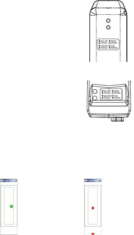
LEDs
The two LEDs, on the back of the FARO Laser
Line Probe, indicate the distance to the target
object from the FARO Laser Line Probe.
Remember, data is only sent to the computer
when the FARO Laser Line Probe is in range.
• Out of Range (two Red LEDs). The Laser Line
Probe is too close or too far from the part.
• Center Range (two Green LEDs) The Laser
Line Probe is in the center of the range.
• Near Range (top Green LED only) The Laser
Line Probe is in range, closer to the part.
• Far Range (bottom Green LED only) The
Laser Line Probe is in range, farther from the
part.
Additionally, the software uses the RANGE
FINDER dialog box to show the distance and
position from the FARO Laser Line Probe to
your part.
Range Finder
The FARO Laser Line Probe software has a RANGE FINDER dialog box.
This dialog box graphically displays the laser to part distance and the
area of the laser line that the camera is processing.
When the FARO Laser Line Probe is within the operating range, the
center of the target displays as a small box in the RANGE FINDER dialog
box, see Figure 4-9.
The box moves as the FARO Laser Line Probe moves:
Figure 4-9 Laser Line Probe in range Figure 4-10 Laser Line Probe not in range
08M52E00_FaroArm_EDGE.book Page 46 Friday, October 1, 2010 11:14 AM
FaroArm®EDGE™ Manual
September 2010 - DRAFT
47
Chapter 4: Probes
• Up - as you move the Laser Line Probe closer to your part
• Down - as you move the Laser Line Probe farther from your part
• Left - the right side of the line is in range
• Right - the left side of the line is in range
The target box changes color:
• Green - all of the laser is in range
• Blue - some of the laser is in range
• Red - none of the laser is in range
When the FARO Laser Line Probe is outside of the operating range, the
target box moves to a side of the RANGE FINDER dialog box and an
arrow in the center of the dialog box points to the target box, see Figure
4-10.
If the FARO Laser Line Probe is set to automatic exposure, there is an
additional symbol in the upper left corner of the RANGE FINDER dialog
box. The symbol changes describes the exposure:
• Red Minus Sign (-) - low exposure
• Green Circle (O) - good exposure
• Red Plus Sign (+) - high exposure
For more information, see “FARO Laser Line Probe Settings” on
page 57.
Software Setup
The EDGE/FARO Laser Line Probe system can be used with many
software packages. Refer to the particular application software for
installation and proper use of the software with the FARO Laser Line
Probe.
NOTE: Some software packages automatically add the EDGE
software driver to your computer. To ensure that you have the latest
version of the EDGE software driver, install the CD-ROM found
inside your FARO Laser Line Probe Case.
Calibration
After you complete the installation and warm-up of the FARO Laser
Line Probe and the standard probe, this system of probes must be
calibrated. Calibration requires measuring the FARO Calibration Sphere
or FARO Calibration Plate, with the standard probe and the FARO Laser
Line Probe.
08M52E00_FaroArm_EDGE.book Page 47 Friday, October 1, 2010 11:14 AM
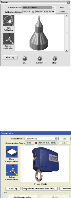
FaroArm®EDGE™ Manual
September 2010 - DRAFT
48
Chapter 4: Probes
NOTE: Clean the top and bottom lenses with the cloth from the FARO
Laser Line Probe Case. Dirt and grease on either lens can cause poor
results.
1 In your measuring software, start the PROBE command.
2 Choose a standard ball probe, 6mm or 3mm.
NOTE: If your ball probes are stamped with the exact diameter, enter
the exact diameter in the MODIFY PROBE dialog box for each ball
probe. See “Edit Probe” on page 84.
3 Calibrate the standard ball probe using the single hole calibration
method. See “Hole Method” on page 89.
4In the P
ROBES dialog box, choose the Laser Probe probe in the
CURRENT PROBE drop-down window.
5 Choose the PLANE CALIBRATION or the SPHERE
CALIBRATION button.
6 You can choose to use the previously measured plane or sphere, or
measure the plane or sphere. Click OK to calibrate the FARO Laser
Line Probe, or measure the plane or sphere.
Figure 4-11 Standard ball probe
Figure 4-12 Probes dialog box
08M52E00_FaroArm_EDGE.book Page 48 Friday, October 1, 2010 11:14 AM

FaroArm®EDGE™ Manual
September 2010 - DRAFT
49
Chapter 4: Probes
• The laser turns on and the laser beam is visible unless you are
measuring the plane or sphere. After you successfully measure the
plane or sphere, the laser turns on and the laser beam is visible.
Sphere Calibration
Calibrate the FARO Laser Line Probe. You will digitize 24 points in
three positions.
NOTE: Avoid touching both lenses. Clean the top and bottom lenses
with the cloth from the FARO Laser Line Probe Case. Dirt and grease
on either lens can cause poor results.
1 Digitize eight points on the top of the calibration sphere with the
FARO Laser Line Probe pointing in position #1, see Figure 4-13.
Figure 4-13 Calibration Positions
Digitize two points in the Near range
with the center of the laser. One point
on the upper half of the calibration
sphere and the other on the lower half.
Digitize two points in the Far range
with the center of the laser. One point
on the upper half of the calibration
sphere and the other on the lower half.
Position #1
Position #2
Position #3
08M52E00_FaroArm_EDGE.book Page 49 Friday, October 1, 2010 11:14 AM
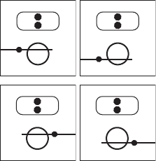
FaroArm®EDGE™ Manual
September 2010 - DRAFT
50
Chapter 4: Probes
Digitize two points in the Center
range with the left side of the laser.
One point on the upper half of the
calibration sphere and the other on the
lower half.
Digitize two points in the Center
range with the right side of the laser.
One point on the upper half of the
calibration sphere and the other on the
lower half.
08M52E00_FaroArm_EDGE.book Page 50 Friday, October 1, 2010 11:14 AM
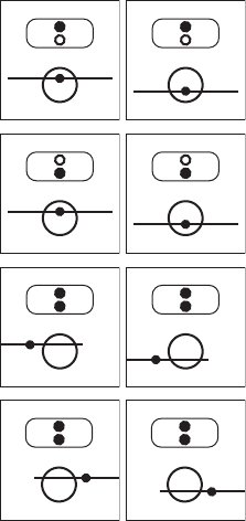
FaroArm®EDGE™ Manual
September 2010 - DRAFT
51
Chapter 4: Probes
2 Digitize eight points on a side of the calibration sphere with the
FARO Laser Line Probe pointing in position #2, see Figure 4-13.
Digitize two points in the Near range
with the center of the laser. One point
on the upper half of the calibration
sphere and the other on the lower half.
Digitize two points in the Far range
with the center of the laser. One point
on the upper half of the calibration
sphere and the other on the lower half.
Digitize two points in the Center
range with the left side of the laser.
One point on the upper half of the
calibration sphere and the other on the
lower half.
Digitize two points in the Center
range with the right side of the laser.
One point on the upper half of the
calibration sphere and the other on the
lower half.
08M52E00_FaroArm_EDGE.book Page 51 Friday, October 1, 2010 11:14 AM

FaroArm®EDGE™ Manual
September 2010 - DRAFT
52
Chapter 4: Probes
3 Digitize eight points on the front of the calibration sphere with the
FARO Laser Line Probe pointing in position #3, see Figure 4-13.
The digitized calibration points then calculate and the CALIBRATION
STATUS updates. If the probe passes, the current date and time is added
to the probe information. You can view the details for all probe
calibrations by clicking the VIEW LOG button. See “View Log” on
page 95.
You now have two probes to digitize your part. Use the PROBES
command to switch between the standard ball probe and the FARO
Laser Line Probe.
NOTE: If you remove the FARO Laser Line Probe, you must re-
calibrate the standard ball probe to guarantee the accuracy of the
measurements. For more information, see “Compensate Probe” on
page 86.
Plane Calibration
Calibrate the FARO Laser Line Probe. You will digitize the FARO
Calibration Plate, once with the ball probe, and then three times with the
FARO Laser Line Probe.
Digitize two points in the Near range
with the center of the laser. One point
on the upper half of the calibration
sphere and the other on the lower half.
Digitize two points in the Far range
with the center of the laser. One point
on the upper half of the calibration
sphere and the other on the lower half.
Digitize two points in the Center
range with the left side of the laser.
One point on the upper half of the
calibration sphere and the other on the
lower half.
Digitize two points in the Center
range with the right side of the laser.
One point on the upper half of the
calibration sphere and the other on the
lower half.
08M52E00_FaroArm_EDGE.book Page 52 Friday, October 1, 2010 11:14 AM

FaroArm®EDGE™ Manual
September 2010 - DRAFT
53
Chapter 4: Probes
1 Digitize the White area of the FARO Calibration Plate with the ball
probe.
• Touch the white surface with the ball probe and press the FRONT
button.
• Digitize eight points on the white surface.
NOTE: Digitize each point near an edge of the surface to avoid
marring the middle of the surface.
• Pull the probe away from the surface and press the BACK button.
The flatness of the white surface is calculated and the results are
displayed in the dialog box. If the results Fail, click the RETRY button
to redigitize the white surface. Click OK to continue.
NOTE: Avoid touching both lenses. Clean the top and bottom lenses
with the cloth from the FARO Laser Line Probe Case. Dirt and grease
on either lens can cause poor results.
8
76
5
43 2
1
08M52E00_FaroArm_EDGE.book Page 53 Friday, October 1, 2010 11:14 AM
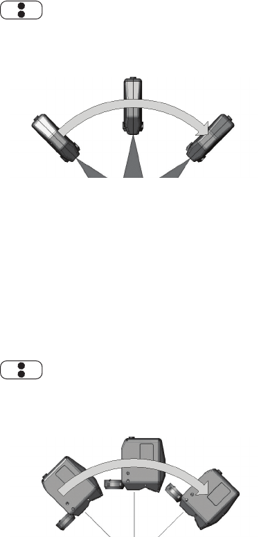
FaroArm®EDGE™ Manual
September 2010 - DRAFT
54
Chapter 4: Probes
2 Digitize the white area of the FARO Calibration Plate with the FARO
Laser Line Probe in a sweeping motion. You should collect at least
200 scan lines in the FARO Laser Line Probe calibration. If not,
repeat the calibration moving the FARO Laser Line Probe slower in
each step.
• Aim the laser line at the middle of the white surface.
• Move the FARO Laser Line Probe until the laser is in the Center
Range. .
• Press the FRONT button and move the FARO Laser Line Probe
while pointing to the center of the white surface. Rotate the FARO
Laser Line Probe as much as possible - at least 90 degrees.
• Press the BACK button.
3 Digitize the white area of the FARO Calibration Plate with the FARO
Laser Line Probe in a sweeping motion. You should collect at least
200 scan lines in the FARO Laser Line Probe calibration. If not,
repeat the calibration moving the FARO Laser Line Probe slower in
each step.
• Rotate the FARO Laser Line Probe 90°.
• Aim the laser line at the middle of the white surface.
• Move the FARO Laser Line Probe until the laser is in the Center
Range. .
• Press the FRONT button and move the FARO Laser Line Probe
while pointing to the center of the white surface. Rotate the FARO
Laser Line Probe as much as possible - at least 90 degrees.
08M52E00_FaroArm_EDGE.book Page 54 Friday, October 1, 2010 11:14 AM
FaroArm®EDGE™ Manual
September 2010 - DRAFT
55
Chapter 4: Probes
• Press the BACK button.
08M52E00_FaroArm_EDGE.book Page 55 Friday, October 1, 2010 11:14 AM

FaroArm®EDGE™ Manual
September 2010 - DRAFT
56
Chapter 4: Probes
4 Digitize the White area of the FARO Calibration Plate with the FARO
Laser Line Probe.
• Aim the laser line at the middle of the white surface.
• Move the FARO Laser Line Probe until the laser is closer than the
Near Range. .
• Press the FRONT button and slowly move the FARO Laser Line
Probe beyond the Far Range while pointing to the center of
the white surface.
• Press the BACK button.
The digitized calibration points then calculate and the CALIBRATION
STATUS updates. If the probe passes, the current date and time is added
to the probe information. You can view the details for all probe
calibrations by clicking the VIEW LOG button. See “View Log” on
page 95.
You now have two probes to digitize your part. Use the PROBES
command to switch between the standard ball probe and the FARO
Laser Line Probe.
NOTE: If you remove the FARO Laser Line Probe, you must re-
calibrate the standard ball probe to guarantee the accuracy of the
measurements. For more information, see “Compensate Probe” on
page 86.
DRO
Some software packages add a Digital ReadOut (DRO) window to the
screen. The DRO window displays the current location of the probe in
the current coordinate system.
• If the FARO Laser Line Probe is in range, the X, Y, Z coordinate is
the center of the laser line. Note that this may not be the center of the
complete laser line because some part of the laser line may be out of
range.
08M52E00_FaroArm_EDGE.book Page 56 Friday, October 1, 2010 11:14 AM
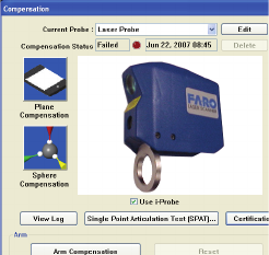
FaroArm®EDGE™ Manual
September 2010 - DRAFT
57
Chapter 4: Probes
• If the FARO Laser Line Probe is out of range, then no coordinate is
available and the DRO displays a row of asterisks (******).
FARO Laser Line Probe Settings
Modify the settings of the FARO Laser Line Probe for your part. The
default settings are for digitizing the calibration sphere or plane that has
an opaque white surface. You can control the following:
• Scan Rate - the number of lines per second that the FARO Laser Line
Probe records and sends to your current file. Fewer lines per second
requires you to move the FARO Laser Line Probe slower.
• Scan Density - the amount of points each line contains. More points in
each line creates a larger file. If you are digitizing a relatively flat
surface, use less points.
• Material - controls the camera which records the laser line. Different
part material colors and textures reflect the laser line differently.
• Advanced Settings - controls the exposure settings of the camera.
To change the FARO Laser Line Probe settings:
• Choose the Laser Probe probe in the PROBES dialog box
• Click the EDIT button.
Figure 4-14 Probes dialog box
08M52E00_FaroArm_EDGE.book Page 57 Friday, October 1, 2010 11:14 AM
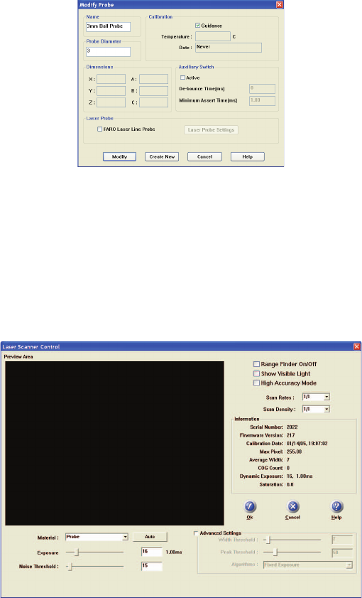
FaroArm®EDGE™ Manual
September 2010 - DRAFT
58
Chapter 4: Probes
In the MODIFY PROBE dialog box, you will see all of the information
about the FARO Laser Line Probe.
• Click the LASER PROBE SETTINGS button to modify the settings
of the FARO Laser Line Probe.
Line Probe Settings
Choose the LASER PROBE SETTINGS button to show the FARO
LASER LINE PROBE CONTROL dialog box. When the FARO Laser Line
Probe is within the operating range, you will see the line in the PREVIEW
AREA of the dialog box.
• Disable the RANGE FINDER dialog box by clearing the Range Finder
On/Off check box.
Figure 4-15 Modify Probe dialog box
Figure 4-16 FARO Laser Line Probe Control dialog box
08M52E00_FaroArm_EDGE.book Page 58 Friday, October 1, 2010 11:14 AM
FaroArm®EDGE™ Manual
September 2010 - DRAFT
59
Chapter 4: Probes
• Select the SHOW VISIBLE LIGHT check box to add all visible light to
the Preview window.
NOTE: Adding all visible light to the preview window will decrease
the number of frames per second sent to the computer and should only
be used when diagnosing problems with the FARO Laser Line Probe.
• Select the HIGH ACCURACY MODE check box to operate the FARO
Laser Line Probe in the High Accuracy mode. High Accuracy mode
can improve the performance of the FARO Laser Line Probe by up to
30%, but reduces your field of view by 1/2 and shortens your
effective maximum scanline width to 2/3 of the normal width.
Scan Rate and Density
Use the Scan Rate Density settings for data reduction. Reducing the
number of points the FARO Laser Line Probe collects can improve
system performance, increase scanning speed and potentially reduce
unwanted noisy data.
• Scan Rate - choose the number of scan lines per second. 1/1 is the
normal rate of scan lines per second, set this to discard scan lines.
NOTE: Always set the scan rate to 1/1 when calibrating the FARO
Laser Line Probe.
• Scan Density - choose the number of points on each scan line. 1/1 is
all of the points on the laser line, set this to discard points on each
line.
• Information - displays the unique information for the current FARO
Laser Line Probe.
Basic Settings
08M52E00_FaroArm_EDGE.book Page 59 Friday, October 1, 2010 11:14 AM
FaroArm®EDGE™ Manual
September 2010 - DRAFT
60
Chapter 4: Probes
•From the MATERIAL drop-down window choose any existing material
setting. Use the commands in this drop-down window to save
material settings.
NOTE: The current material setting is stored on your computer and in
the EDGE. If you connect the EDGE to another computer, the current
material will be Unknown. Save the material settings to copy the
settings from the EDGE to the new computer.
• Click the AUTO button to set the Exposure and Noise Threshold
levels for the current material. Hold the FARO Laser Line Probe in
position, pointing at the surface, until the process completes. You can
also set the values manually:
• Exposure - How long the “shutter” is open and the sensor is
exposed to light in the camera. Enter a number from 1 to 80; the
corresponding value in milliseconds appears next to it. Light colors
and reflective surfaces are better captured with low exposure levels.
Darker colors typically require higher exposure levels. The default
value is 16.
• Noise Threshold - The FARO Laser Line Probe measures the
intensity, or return power, of all pixels and each pixel of the laser
line projected onto a surface using a scale from 0 to 255. All data
having intensity below the Noise Threshold value is considered
noise or “chatter” that is too faint to be usable and is simply
ignored. Dark colors or surfaces that tend to absorb light may
benefit from a lower value. Increasing this value will filter out more
data. Setting this value to 255 considers all data to be noise. The
default value is 15.
Advanced Settings
• Select the ADVANCED SETTINGS check box to modify more material
settings:
• Width Threshold - When determining the Center of Gravity (COG)
for the laser line, groups of pixels are analyzed. This sets the
minimum number of pixels to define a COG group of pixels. The
default value is 5. This means that if the FARO Laser Line Probe
picks up several clusters of light in one column, due to angle of
incidence, reflection, or any other external interference, only
clusters with at least 5 pixels will be considered COG candidates.
Pixels must also meet the Noise Threshold criteria, which is a value
of 2.
08M52E00_FaroArm_EDGE.book Page 60 Friday, October 1, 2010 11:14 AM
FaroArm®EDGE™ Manual
September 2010 - DRAFT
61
Chapter 4: Probes
• Peak Threshold - For a COG group to be valid, one of the pixels
must be above this value. The default value is 50. Increasing the
Peak Threshold is useful with reflective surfaces that may shine or
produce flares in the FARO Laser Line Probe. If a FARO Laser
Line Probe column captures more that one laser light source, only
the groups or clusters with at least one pixel at Peak Threshold will
be considered. Groups must also meet Noise Threshold and Width
Threshold criteria.
• Algorithm - Select an exposure setting:
•Automatic - Full: As you digitize, the Exposure setting
automatically adjusts to maintain the proper saturation level. This
automatic mode uses the entire exposure range of the FARO
Laser Line Probe. In this mode, you may notice a slight decrease
in speed as the FARO Laser Line Probe automatically adjusts
from one surface type to another.
•Automatic - Highly Reflective: This is an automatic setting for
use with reflective, or shiny, materials. This automatic mode uses
the lower half of the exposure range of the FARO Laser Line
Probe.
•Automatic - Normal: This is an automatic setting for use with
non-reflective, or dull, materials. This automatic mode uses the
upper half of the exposure range of the FARO Laser Line Probe.
•Fixed Exposure - The Exposure setting is constant.
NOTE: The three Automatic settings disable the AUTO button
and ignore the Exposure and Noise Threshold sliders.
Choosing any of the three Automatic settings adds an exposure
indicator to the RANGE FINDER dialog box. In the RANGE FINDER
dialog box:
• A green dot in the upper left-hand corner of the RANGE FINDER
dialog box indicates that the exposure has been adjusted and
you are ready to scan.
• The indicator changes to either a red “+” (plus)
or “-” (minus) sign indicating that the FARO Laser Line Probe
is either over-exposed or under-exposed, and it is automatically
adjusting the exposure. The FARO Laser Line Probe does not
collect data during this adjustment, however this automatic
adjustment process is very fast.
For more information, see “Range Finder” on page 46.
08M52E00_FaroArm_EDGE.book Page 61 Friday, October 1, 2010 11:14 AM
FaroArm®EDGE™ Manual
September 2010 - DRAFT
62
Chapter 4: Probes
During the calibration of the FARO Laser Line Probe, this setting
temporarily changes to Automatic - Normal except when using
Fixed Exposure. For more information, see “Calibration” on
page 47.
• Choose Save As... in the MATERIAL drop-down window to save a
material setting.
In general, the default values for all settings described here will yield
acceptable data on most surfaces. The EXPOSURE parameter requires
more frequent adjustments based on the different surface finishes you
are scanning.
Keep in mind that given the vast range of colors, textures and finishes,
there is no exact science for these FARO Laser Line Probe Settings that
work best on a particular surface. Finding the optimum settings may
require some practice.
Additional Considerations
• First, if accuracy is not an issue, even failing probe calibration will
not prevent you from using the FARO Laser Line Probe to show the
concept of gathering point clouds quickly and easily, directly into
software applications. The ScanArm does use the new probe
calibration, even if it fails.
• Second, if the probe calibration does fail, you should look at the probe
calibration log to see by how much. If the error is acceptable, you
should be able to scan effectively for medium accuracy applications.
• Third, if you need to measure in a high accuracy application, or you
have a requirement that the probe calibration pass, make sure you
allow the FARO Laser Line Probe to warm-up for the amount of time
recommended for your model. See “Diagnosing FARO Laser Line
Probe Accuracy Problems” on page 93.
08M52E00_FaroArm_EDGE.book Page 62 Friday, October 1, 2010 11:14 AM
FaroArm®EDGE™ Manual
September 2010 - DRAFT
63
Chapter 4: Probes
08M52E00_FaroArm_EDGE.book Page 63 Friday, October 1, 2010 11:14 AM
FaroArm®EDGE™ Manual
September 2010 - DRAFT
64
Chapter 4: Probes
08M52E00_FaroArm_EDGE.book Page 64 Friday, October 1, 2010 11:14 AM
FaroArm®EDGE™ Manual
September 2010 - DRAFT
65
Chapter 4: Probes
08M52E00_FaroArm_EDGE.book Page 65 Friday, October 1, 2010 11:14 AM
FaroArm®EDGE™ Manual
September 2010 - DRAFT
66
Chapter 4: Probes
08M52E00_FaroArm_EDGE.book Page 66 Friday, October 1, 2010 11:14 AM
FaroArm®EDGE™ Manual
September 2010 - DRAFT
67
Chapter 5: Accuracy
Chapter 5: Accuracy
Calibration and Certification
The EDGE is designed to endure the typical stress and impact loads of a
“factory floor” measuring tool, as well as survive multiple
transportation cycles while maintaining its accuracy throughout its
usable life. In order to fully appreciate what is meant by “Lifetime
Calibration,” you must first understand several basic concepts of
measurement equipment.
Calibration versus Certification
In most cases the terms “calibration and certification” are used together,
and are often mistakenly used interchangeably. This generally occurs
because traditional Coordinate Measuring Machines are often calibrated
every time they are certified. In reference to the EDGE, there are two
types of calibration: the EDGE calibration and the probe calibration.
EDGE Calibration
Calibration is the procedure by which a measurement device is
optimized to perform accurate measurements. This may be done
through mechanical adjustments, as well as software corrections.
Specialists at FARO’s production facility perform the factory
calibration. This calibration utilizes patented hardware and software
(not available to the user) to determine the true dimensions and
kinematics of the EDGE. The results of the factory calibration are
imprinted to memory located in the EDGE electronics. The EDGE is
permanently calibrated, such that it does not require mechanical
adjustments during normal operation.
The EDGE will only lose its calibration (stop functioning within
FARO's published standards) if one or more of the following occurs:
• Bending of the transfer cases (long, tube sections).
• Damage to the encoder-bearing interface joints (where tubes, bearings
and encoders are mated).
08M52E00_FaroArm_EDGE.book Page 67 Friday, October 1, 2010 11:14 AM
FaroArm®EDGE™ Manual
September 2010 - DRAFT
68
Chapter 5: Accuracy
• Failure of the encoder-electronics system (changes motion into
electrical data).
• Physical (plastic) deformation can occur in the EDGE after excessive
impact with another object or an end-stop. The impact may cause the
transfer cases to bend, the joint housings to deform, or the encoder-
bearing interface pin system to loosen.
Any of these problems require FARO’s Customer Service Department
to disassemble the EDGE, repair the necessary item(s), and perform a
factory calibration. A factory calibration is necessary since the physical
nature of the EDGE has been changed.
Since the EDGE will always require repair if it loses calibration, and
will only lose calibration if it is damaged, there is never a need for a
field or user-site calibration.
EDGE Certification
The measuring software has commands that allow you to perform tests
that certify the accuracy and repeatability of your EDGE. The
certification commands allow you to test the EDGE using a single hole,
a ball bar, or a step gauge.
The values measured in all of these certifications include 100% of the
measured points. We will always refer to this as the “Max. minus Min.
over Two,” or the Maximum measurement subtracting from the
Minimum measurement divided by two (Max.-Min.)/2.
If any test fails, print the results and repeat the certification two more
times. Print all of the results and contact FARO’s Customer Service by
Phone, Fax or E-Mail. See “Technical Support” on page 119.
Repeatability
Perform the single point repeatability test to check the probe and
repeatability using a hole or a cone. You must use a firmly secured
object with a hole at least 1mm smaller than the ball probe. If a cone
hole is used, extreme care must be taken to ensure that the probe is
seated at each “measurement.”
• Use a calibrated ball probe. See “Installing Probes” on page 36 and
“Compensate Probe” on page 104.
• Run the Single Point Certification command.
1 Measure points in the hole, or cone, from multiple directions.
08M52E00_FaroArm_EDGE.book Page 68 Friday, October 1, 2010 11:14 AM

FaroArm®EDGE™ Manual
September 2010 - DRAFT
69
Chapter 5: Accuracy
2 Make sure that you move the joints of the EDGE while measuring
the points.
3 Do not digitize a point if any of the encoders reach their end stop.
See “Error and Status Indicators” on page 30.
4 Avoid a position where a degree of freedom is lost in the EDGE.
See “Loss of a Degree of Freedom” on page 71.
Volumetric Accuracy
Perform a Sphere to Sphere or Step Gauge in order to certify the
volumetric accuracy of the equipment.
• Use a calibrated ball probe. See “Installing Probes” on page 36 and
“Compensate Probe” on page 104.
• Run the Sphere to Sphere, or Step Gauge Certification command.
1 Measure points on each sphere, or on each step from multiple
directions.
2 Make sure that you move the joints of the EDGE while measuring
the points.
3 Do not digitize a point if any of the encoders reach their end stop.
See “Error and Status Indicators” on page 30.
4 Avoid a position where a degree of freedom is lost in the EDGE.
See “Loss of a Degree of Freedom” on page 71.
Figure 5-1 Single Point Certification
08M52E00_FaroArm_EDGE.book Page 69 Friday, October 1, 2010 11:14 AM
FaroArm®EDGE™ Manual
September 2010 - DRAFT
70
Chapter 5: Accuracy
EDGE Performance
The EDGE performance testing standard is the North American ASME
or European ISO standard. EDGE test methods are a subset of those
given in the B89.4.22 standard. Single-point repeatability is measured
using a hard probe in a reference hole. Volumetric performance is
measured using a traceable length artifact. Measurements are well
distributed in all regions of the working volume.
Single Point Articulation Performance Test (SPAT)
The EDGE’s calibrated probe is placed into the calibration cone, or a
conical socket, and individual points are automatically measured as you
move the elbow of the EDGE from one side to the other, and back. Each
individual point measurement is analyzed as a range of deviations in X,
Y, Z. This test is a method for determining articulating measurement
machine repeatability. For more information, see “Single Point
Articulation Test (SPAT)” on page 91.
• FARO reports this as (Max.-Min.)/2, or the Single Point repeatability
value.
This represents the error as the range of error between the least value
and the highest value.
08M52E00_FaroArm_EDGE.book Page 70 Friday, October 1, 2010 11:14 AM

FaroArm®EDGE™ Manual
September 2010 - DRAFT
71
Chapter 5: Accuracy
The specifications of your EDGE are listed on the Serial Number label
on the left side of the base.
NOTE: For optimum performance, correctly mounting and operating
the EDGE is very important. For more information, see “EDGE/
ScanArm Performance Verification Checklist” on page 87.
Volumetric Maximum Deviation
This value is determined by using traceable length artifacts, which are
measured at various locations and orientations throughout the working
volume of the EDGE. This test is a method for determining articulating
measurement machine accuracy. The deviation value is the difference
between the measured value and the true, or nominal, value.
Loss of a Degree of Freedom
In a working volume of the EDGE there can be a loss of a degree of
freedom (natural rotation of transfer case). With this loss, temporary
bending occurs on the transfer tubes of the EDGE causing a movement
of the probe position that cannot be recorded by the EDGE’s encoder
system. Measurement results taken in these positions are not accurate.
This condition is never encountered in the calibration of the EDGE.
Common areas of measurement where this loss occurs are:
• when an encoder has reached a hard end-stop,
• directly above the EDGE, or
S/NS/N
ModelModel RevRev Single PointSingle Point
VolumetricVolumetric
Certification Certification
DateDate
MADE IN U.S.A.
P08-02-07-05675
P0826.2
Aug18, 2007
+/- .036 mm.
+/- .025 mm.
Q08-05-08-06548
2.2
May 08, 2008May 08, 2008
+/- .028 mm.
+/- .020 mm.
Rev:
MADE IN
U.S.A
S/N:
Volumetric:
Certification Date:Manufacture Date:
Single Point:
08M52E00_FaroArm_EDGE.book Page 71 Friday, October 1, 2010 11:14 AM
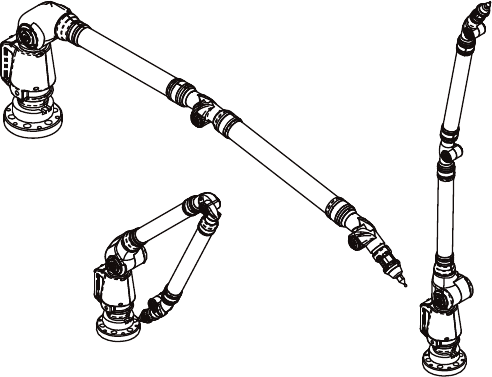
FaroArm®EDGE™ Manual
September 2010 - DRAFT
72
Chapter 5: Accuracy
• in close to the base of the EDGE.
The EDGE should always feel fluid in its movement. If excessive force
is needed to move to a measuring location, a degree of freedom has
probably been lost. The following figures illustrate some of the possible
positions of a EDGE where a degree of freedom has been lost.
Figure 5-2 Loss of a Degree of Freedom
08M52E00_FaroArm_EDGE.book Page 72 Friday, October 1, 2010 11:14 AM