FARO Technologies 14000 PORTABLE LASER LINE MEASUREMENT ARM User Manual FARO EDGE Laser ScanArm Users Manual
Faro Technologies, Inc. PORTABLE LASER LINE MEASUREMENT ARM FARO EDGE Laser ScanArm Users Manual
Contents
- 1. Users Manual 1
- 2. Users Manual 2
Users Manual 2
FaroArm®EDGE™ Manual
September 2010 - DRAFT
73
Chapter 6: Maintenance and Troubleshooting
Chapter 6: Maintenance and
Troubleshooting
Normal Maintenance
EDGE
The EDGE is a precision measurement device that contains many
sensitive components, and it should be handled with care. Take the
following precautions to prevent problems from developing with your
system:
• Place a dust cover over the EDGE when not in use.
• Clean with a dry dust cloth. For heavy dirt buildups, use a very small
amount of warm water and gently clean the EDGE. Be very careful
not to bend the EDGE while cleaning.
• Check the cables for damage to outside insulation, connectors, and
pins.
• Do not lubricate the EDGE.
The EDGE is calibrated at FARO’s production facility and should only
need to be recalibrated after the unit has been subjected to a shock that
removes surface material or causes bending. Periodic certification tests
should be completed to certify the EDGE accuracy and repeatability.
See “EDGE Certification” on page 68.
FARO recommends you return your EDGE to a service center, once a
year, for our annual certification and a 15 point check up.
Host Computer
The computer is an electronic device containing many sensitive
components. It should be handled with care. Here are some steps you
can take to prevent damage to your system:
• Never use the computer in harsh environments where it may be
subjected to rapid temperature change or excessive dust.
• Never expose the computer to excessive shock or vibration.
08M52E00_FaroArm_EDGE.book Page 73 Friday, October 1, 2010 11:14 AM
FaroArm®EDGE™ Manual
September 2010 - DRAFT
74
Chapter 6: Maintenance and Troubleshooting
• Prevent overheating by keeping the computer's air vents clear of any
obstructions.
• Never place anything on top of the computer when it is recharging or
operating. This can cause the computer to overheat.
• Do not operate the computer from an AC outlet where voltage
fluctuates excessively. Use a power strip with a surge protector.
• Do not use an AC adapter other than the one supplied with the
computer.
• Do not push on the LCD screen excessively or subject it to shocks.
• Do not expose the LCD screen to direct sunlight, even through a
window.
• Do not hold the computer by the LCD panel.
• Do not try to force the LCD screen beyond its fully opened position.
CAUTION: In the rare event that you should see or smell anything
which indicates overheating (smoke or a strange smell), turn off the
power immediately and contact your dealer.
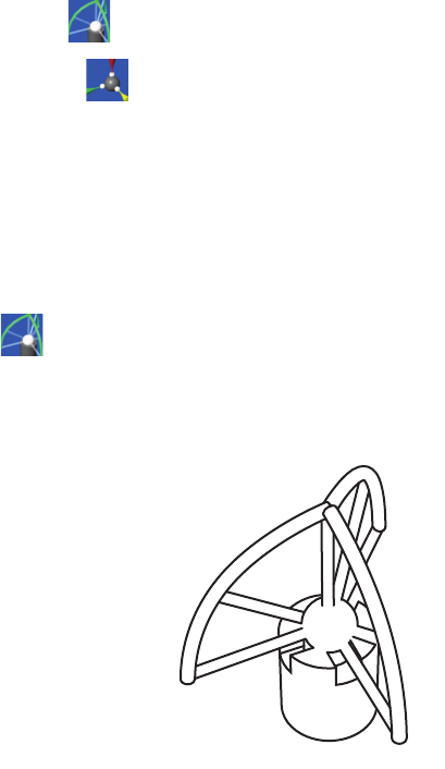
Mounting Stiffness Test
The EDGE is portable and can be mounted in a variety of environments.
The EDGE is counterbalanced, and it is the nature of counterbalancing
that restoring forces may exist in the mounting due to the applied forces
generated by the counterbalancing mechanism. The reaction forces will
result in deformations in the mounting, which degrade the performance
of the EDGE if the deformations are sufficiently large.
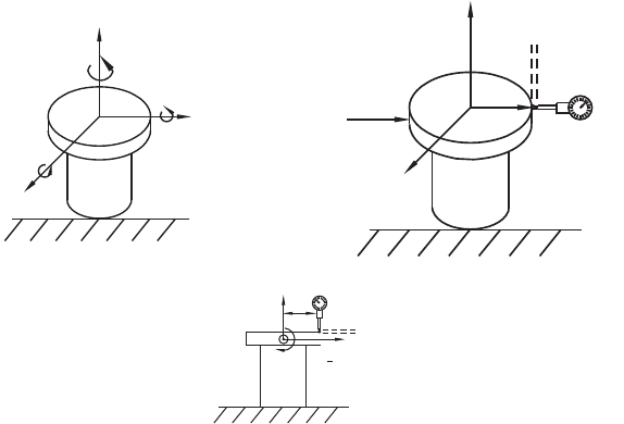
The primary forces encountered due to counterbalancing are translation
and torsion. These forces are illustrated below. The forces can be further
described along or about the three major axes of a coordinate system at
the mounting base. The translation forces (F) along the axes and the
moments (M) about the axes result in deformations of the base.
The deformation due to the translation force can be measured. You must
apply forces (lb. or N) using a calibrated load cell at the mounting
interface to the maximum level required and measure the associated
deformation (in. or mm). The torsional forces or moments at the base
are generated by using a calibrated torque wrench. The deformations
can be described as a slope (in./in. or mm/mm) and can be measured.
08M52E00_FaroArm_EDGE.book Page 74 Friday, October 1, 2010 11:14 AM
FaroArm®EDGE™ Manual
September 2010 - DRAFT
75
Chapter 6: Maintenance and Troubleshooting
The deformations must not exceed the deformation reported at
certification.
In general, the excessive translation deformations are added directly to
the certified accuracy, while the excessive angular deformations of the
base affect accuracy as a more complicated trigonometric function of
the length of the reach.
Temperature Considerations
FARO was awarded the U.S. patent #5,402,582, and worldwide patents
are pending, on the concept and the methods for temperature
compensation of portable CMM devices. This brief overview is meant
only as the most general of descriptions.
To maintain certified accuracy in a multitude of environments, the
monitoring of temperature and the rate of temperature change is
required. Only the EDGE employs a software/hardware solution where
a semiconductor temperature sensor is built into each joint.
The temperature is continuously monitored and the difference over time
is then applied to the mathematical formulas or kinematics, which
define the position of the EDGE in three-dimensional space. Link length
corrections are made constantly by the inboard processor, which adjusts
Forces Encountered due to
Counterbalancing Displacement due to Force
Rotation due to Torque
FY
YMY
Mx
Moments (about X)
XF
X Forces (along X)
MZ
Z
FZ
Force
Displacement
due to Force
D
L
D
D
Rotation due to Torque
L
T
08M52E00_FaroArm_EDGE.book Page 75 Friday, October 1, 2010 11:14 AM
FaroArm®EDGE™ Manual
September 2010 - DRAFT
76
Chapter 6: Maintenance and Troubleshooting
the kinematics and constantly adapts the output to changing
environmental temperature.
However, because different components heat or cool at different rates,
the device is expected to reach a steady state temperature within a ±3
degree (Celsius) bandwidth for five minutes before measurements can
be taken. For convenience, the electronics system is programmed to
generate an error message when the temperature exceeds a ±3 degree
bandwidth. There is also a built-in routine for the establishment of
temperature stability; whereby, the device monitors itself for five
minutes and indicates to the user that it is ready for use.
Electrostatic Discharge (ESD)
Electrostatic Discharge (ESD) refers to pulses generated by the
discharge of loaded objects and/or people. The charge usually comes
from friction between materials, at least one of which is a nonconductor.
• Although these units are protected against damage by ESD, extra care
and proper ESD procedures still must be observed and followed.
If an error occurs because of ESD, check the Error Message displayed
on the screen and follow the steps below to resume normal operation. If
you experience anything out of normal operation:
1 Turn off the EDGE.
2 Wait for at least five seconds before powering the unit on.
This should restore communication with the host computer.
ESD Best Practices
The following is a list of equipment and best practices to avoid ESD
events.
Wrist Straps - Wrist straps fit snugly around a person’s wrist and are
connected to an ESD ground point (never earth ground) or to a grounded
08M52E00_FaroArm_EDGE.book Page 76 Friday, October 1, 2010 11:14 AM
FaroArm®EDGE™ Manual
September 2010 - DRAFT
77
Chapter 6: Maintenance and Troubleshooting
mat. A poor connection with a wrist strap is associated with a loose fit
or dry skin (use an ESD lotion for dry skin). A wrist strap may be used if
an approved ESD smock is not available. However, wrist straps do not
shield ESD sensitive components from damage induced by the wearer’s
clothing.
Heel Straps - Heel straps should be placed so that they make contact
with a person’s ankle. Static charges are dissipated through the floor by
means of a Conductive Flooring. When seated, heel straps do not offer
the protections required to dissipate a static charge.
ESD Lotion - ESD lotion provides a better connection between the user
and a smock, heel strap or wrist strap. This may need to be reapplied if
the smock or straps are removed.
Smocks - ESD smocks are designed to dissipate static fields created by
a wearer’s shirt. These must be worn at all times within an ESD
Sensitive area. All buttons must be secured when working. Smocks are
to be connected to an ESD ground point (never earth ground) or to a
grounded mat. While the smock is connected and properly grounded,
wrist straps are unnecessary.
ESD Chairs - ESD chairs have a ground strap which comes in contact
with a grounded mat or conductive flooring and dissipates charges
safely to ground.
Table Mats - Table mats are made of a dissipative material and must be
grounded individually to earth ground.
Hand Tool Requirements - Hand tools must be stored in non-insulating
or charging stations. New hand tools should be ESD-safe (non-
generating and dissipative).
Floor Mats - Floor mats are made of a dissipative material and must be
grounded individually to earth ground. This is required if no conductive
flooring is installed.
Ground Connections - Any earth ground connection is sufficient.
Conductive Flooring - Conductive flooring must be installed per
manufacturer specifications and be connected to earth ground.
Wrist/Heel Strap Tester - These provide a method for checking the
function of smocks, heels straps and cable connections on an individual
user.
Ionizers - An Ionizer floods the air with positive and negative ions,
which eliminate static charges. This must be installed so that the airflow
08M52E00_FaroArm_EDGE.book Page 77 Friday, October 1, 2010 11:14 AM
FaroArm®EDGE™ Manual
September 2010 - DRAFT
78
Chapter 6: Maintenance and Troubleshooting
blows across the workbench (or down on the workbench for overhead
units).
Constant Ground Monitors - Constant monitors are connected to a
workstation mat and operator and will sound an audible alarm if any
ground is interrupted.
08M52E00_FaroArm_EDGE.book Page 78 Friday, October 1, 2010 11:14 AM
FaroArm®EDGE™ Manual
September 2010 - DRAFT
79
Chapter 6: Maintenance and Troubleshooting
Troubleshooting
Error message on host computer.
• Contact FARO’s Customer Service by Phone, Fax or E-Mail. See
“Technical Support” on page 119. Have the message ready.
Probe calibration fails.
• Check that the diameter stamped on the probe tip matches the tip of
the current probe. See “Edit Probe” on page 102.
• Make sure the EDGE probe is secure. Only hand-tighten the probe
with the 12mm wrench. Do not over-tighten the probe.
• Make sure that the calibration hole, cone or sphere is located about
2/3 the distance of the EDGE from the base.
• Make sure that the calibration cone, or sphere, is securely screwed
into the holder and that the holder is securely fastened to a stable
surface.
• Make sure that probe tip is in contact with hole, cone or sphere.
• Calibrate the probe again, and check that all points were digitized
properly.
• Use the other calibration method (sphere or hole).
Buttons (FRONT & BACK) will not respond.
• Make sure that all of the encoders are referenced. See “Referencing
the Encoders” on page 31.
• Turn auxiliary port OFF. See “Edit Probe” on page 102.
• Check buttons in Diagnostic command. See “Diagnostics” on
page 114.
Single-point certification shows excessive error.
• You must use a ball probe. Check that it is installed correctly. See
“Installing Probes” on page 36.
• Recalibrate probe. See “Compensate Probe” on page 104.
• During the test, watch the probe to ensure flush seating in the hole.
See “EDGE Certification” on page 68.
08M52E00_FaroArm_EDGE.book Page 79 Friday, October 1, 2010 11:14 AM
FaroArm®EDGE™ Manual
September 2010 - DRAFT
80
Chapter 6: Maintenance and Troubleshooting
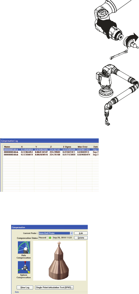
EDGE records points without pressing either button.
• Re-seat the set screw in the EDGE handle. If the set screw is not
seated correctly it causes intermittent contact to the pin underneath,
and random points are taken.
1 Remove any standard EDGE probe.
2 Remove the set screw using a flathead screwdriver.
3 Replace the screw.
NOTE: Be careful not to bottom out the screw. This may cause the
pin underneath to be constantly depressed possibly damaging the
EDGE.
4 Replace the EDGE probe.
Power Issues
If the EDGE is receiving power from the power source, or outlet, but not
powering up the system, the source of this issue may lie in one or all of
the following areas:
• Ensure you are using the correct cables.
• Check the cables and connectors for bent pins or damage and ensure
that the connectors are secure. Replace all cables that show signs of
damage.
• Check the power source (outlet) for proper voltage, current and
grounding. For more information, see “EDGE Power Supply” on
page 14.
Figure 6-1 Handle Screw
08M52E00_FaroArm_EDGE.book Page 80 Friday, October 1, 2010 11:14 AM
FaroArm®EDGE™ Manual
September 2010 - DRAFT
81
Chapter 6: Maintenance and Troubleshooting
• Check the power supply for physical impacts or damage. DO NOT
use a damaged power supply.
• Check functionality of the EDGE. Look for error codes or operation
issues.
NOTE: Power surges, spikes, feedback, and fluctuation in the power
source will affect the equipment and its electronic accessories. Have
you power source inspected by a professional to provide the cleanest
power source possible.
Hardware Communication Issues
This section describes the many issues that prevent good
communication between the EDGE and the host computer.
PLEASE READ BEFORE BEGINNING THE PROCESS
If communication between the computer and the EDGE is lost, or if it
could not be established, the source of this issue may lie in one or all of
the following areas:
• Ensure you are using the correct cables.
NOTE: EDGEs cannot be adapted by a USB to Serial/Parallel adapter
to work on those ports.
• Check the cables and connectors for bent pins or damage and ensure
that the connectors are secure. Replace all cables that show signs of
damage.
• Check that unauthorized software or hardware is not conflicting with
communications; PDAs, digital cameras, scanners, zip drives,
modems and external devices are know to cause these conflicts.
• Check that only the EDGE software is running on the computer.
Ensure multiple sessions of the measuring software is not running.
• Check functionality of the EDGE. Look for error codes or operation
issues.
• Check functionality of power supply or serial box. Look for error
codes or damage to the housing.
08M52E00_FaroArm_EDGE.book Page 81 Friday, October 1, 2010 11:14 AM
FaroArm®EDGE™ Manual
September 2010 - DRAFT
82
Chapter 6: Maintenance and Troubleshooting
• Check functionality of computer's hardware.
• Check power source for proper voltage, current and grounding.
Remove any extension cords and ungrounded cables.
• Check area to eliminate interference. Large motors, welders or items
that may cause vibration or spikes in the power source.
FARO Wireless Connection Issues
• You have setup your connection using your platform specific
Bluetooth Wizard and the FARO Bluetooth Connection Setup utility,
but software application does not find the EDGE.
1 Make sure the EDGE is receiving power and the On/Off switch is
set to the ON position. When the On/Off switch is first set to the ON
position, the blue LED on the front of the EDGE should blink
momentarily.
2 If you are using a Bluetooth USB dongle make sure it is plugged
into a USB port. Also make sure the software associated with the
dongle is running. If you are unsure about this, contact the vendor
who supplied the Bluetooth hardware and software.
3 Open the platform specific Bluetooth Wizard and make sure the
EDGE is still in the list. If not, refresh the list.
If the EDGE is switched on and the PC's Bluetooth hardware is
connected correctly, and the connection is still unavailable
contact FARO’s Customer Service.
4 Open the platform specific Bluetooth Wizard and check which
COM port is configured with the EDGE.
5 Open the FARO Bluetooth Connection Setup utility program and
confirm the COM port setting. Ensure it matches the same port in
the platform specific Bluetooth Wizard list.
Click OK. If the test passes, the EDGE should work normally. If
the test fails, contact FARO’s Customer Service.
If the test passes but your software still does not connect, make
sure your EDGE driver software is current. The latest driver
software may be on a separate CD-ROM that came with your
Bluetooth equipped EDGE, or any other FARO software
package. If you are unsure about what version of the EDGE
driver you are running contact your Customer Service
08M52E00_FaroArm_EDGE.book Page 82 Friday, October 1, 2010 11:14 AM
FaroArm®EDGE™ Manual
September 2010 - DRAFT
83
Chapter 6: Maintenance and Troubleshooting
Representative by Phone, Fax or E-Mail. See “Technical
Support” on page 119.
• You are within the maximum 30' Bluetooth range, but cannot get a
reliable connection.
1 Bluetooth works with a radio frequency, or RF, signal which can be
blocked by obstructions. Metallic obstructions are especially
degrading to the signal. For best results, ensure you have a clear
path between your computer and the EDGE.
FARO Wireless FAQ
• How fast is the connection?
1 Megabit/second.
• What is the range of the FARO Wireless connection?
Approximately 30 feet or 10 meters.
• How many simultaneous Bluetooth wireless connections can be
established with the EDGE driver?
Two.
• Can both USB and Bluetooth wireless EDGEs be connected
simultaneously?
Yes.
• Can a single EDGE connect using both Bluetooth wireless and a USB
cable at the same time?
No. If both are properly connected, the Bluetooth wireless will be
the only active connection for that EDGE.
• Can I use a FARO Laser Line Probe with the FARO Wireless
connection?
Yes.
• Can I add a Bluetooth wireless connection while the EDGE driver is
already running?
No, the EDGE driver must be unloaded before changing any
FARO Wireless settings.
• Why does it take longer for my measuring software to open when I
use the FARO Wireless connection?
08M52E00_FaroArm_EDGE.book Page 83 Friday, October 1, 2010 11:14 AM
FaroArm®EDGE™ Manual
September 2010 - DRAFT
84
Chapter 6: Maintenance and Troubleshooting
The EDGE driver requires more time to initialize when using a
FARO Wireless connection and this translates into slightly
increased load times for the measuring software.
• Why does it take longer for the PROBES dialog box to go away when I
am using a FARO Wireless connection.
Probe data saves in the EDGE and requires more time for this
information to transfer when using the FARO Wireless
connection.
• What happens if I go out of range and lose my connection? What
happens if I turn off the EDGE while it is connected using the FARO
Wireless connection?
Once the EDGE driver detects that the EDGE is no longer
connected, after about 10 seconds, a message appears asking if
you want to restore the FARO Wireless connection. If you click
No, the connection stops. If you click Yes, attempts are made to
restore the connection.
• Why do I continue to see the message asking if I want to continue to
use the FARO Wireless connection?
Either the EDGE has lost power, or it is out of the 30 feet or 10
meters wireless range. After correcting the problem, click Yes to
restore the connection.
FARO i-Probe FAQ
• Can I use an i-Probe on anything other than the EDGE?
Yes. ONLY on a Quantum series FaroArm. Installing the i-Probe
to anything other than a Quantum series FaroArm damages the i-
Probe.
• Can I still use my old probes on the EDGE?
Yes. However you must clear the USE I-PROBE check box in the
PROBE dialog box. For more information, see “Probes” on
page 101.
08M52E00_FaroArm_EDGE.book Page 84 Friday, October 1, 2010 11:14 AM
FaroArm®EDGE™ Manual
September 2010 - DRAFT
85
Chapter 6: Maintenance and Troubleshooting
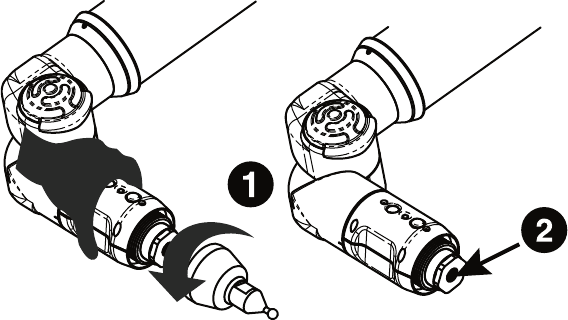
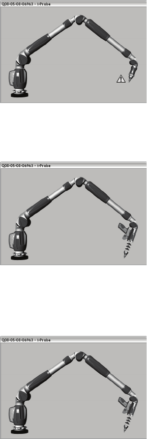
• I have an i-Probe attached but see this error dialog box and can not
measure. What is wrong?
Calibrate the i-Probe. For more information, see “Compensate
Probe” on page 104.
• I have an i-Probe attached but see this error dialog box and can not
measure. What is wrong?
Ensure that the i-Probe is threaded on all the way. If the system
still does not recognize it, the i-Probe may be damaged and may
need to be replaced.
• I have an old probe attached but see this error dialog box and can not
measure. What is wrong?
You must clear the USE I-PROBE check box in the PROBE dialog
box. For more information, see “Probes” on page 101.
08M52E00_FaroArm_EDGE.book Page 85 Friday, October 1, 2010 11:14 AM
FaroArm®EDGE™ Manual
September 2010 - DRAFT
86
Chapter 6: Maintenance and Troubleshooting
• How many i-Probes can a EDGE remember?
112
08M52E00_FaroArm_EDGE.book Page 86 Friday, October 1, 2010 11:14 AM
FaroArm®EDGE™ Manual
September 2010 - DRAFT
87
Chapter 6: Maintenance and Troubleshooting
EDGE/ScanArm Performance Verification
Checklist
If you are experiencing accuracy or repeatability problems with your
EDGE or ScanArm system, this section details proper setup techniques
to help you identify the potential sources of error.
It is important to clearly understand all the “do's and don'ts” in order to
get the most out of every EDGE and ScanArm system.
Issues That Will Degrade Accuracy
Mounting
1 Deflection in mounting.
• Do not mount to any type of wooden surface.
• Do not mount to optical tables such as a “Vibraplane.” The steel
sheet on the top of these tables is thin and will deflect.
2 Folding tripods without using the stabilizing struts are unstable.
3 Heavy-duty stands with wheels down and pins up are unstable.
4 Part deformation due to excessive clamping force.
Calibration
1 Deflection of calibration artifact.
2 Damage to calibration artifact.
• Do not drag the probe over the FARO Calibration Plate during the
plane measurement. Lift the probe in between points to avoid
scratching the surface of the plate.
3 Poor probe calibration technique.
• Do not do short sweeps with the FARO Laser Line Probe during
calibration.
4 Dirty lens.
• Clean the top and bottom lenses with the cloth from the FARO
Laser Line Probe Case. Dirt and grease on either lens can cause
poor results.
Probes
1 Measuring with Point Probes.
2 Measuring with chipped, loose or cracked ball probes.
08M52E00_FaroArm_EDGE.book Page 87 Friday, October 1, 2010 11:14 AM
FaroArm®EDGE™ Manual
September 2010 - DRAFT
88
Chapter 6: Maintenance and Troubleshooting
3 Measuring with Probe extensions. The extensions will deflect.
Measurement Environment
1 Measuring close to an end stop can induce unwanted stress.
2 Binding or hyper-extending the EDGE can cause unnecessary stress.
3 “Leap Frogging” or repositioning the device using the Move Device
Position command.
4 Excessive vibration in the surrounding area can produce unwanted
results.
5 Rapid changes in ambient temperature can cause errors in the EDGE's
automatic temperature compensation.
6 Measuring using poor techniques; minimum number of measured
points per feature, moving while recording individual points, small
coverage area, etc.
NOTE: If the EDGE is mounted on granite, do not measure objects
that are not mounted to the granite.
EDGE Setup
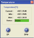
Turn equipment on and allow to warm-up for at least 30 minutes.
Check that ambient temperature is not fluctuating more than 3°C
(5.4°F) over a five minute period.
• In CAM2 Measure, run the DEVICES
>TEMPERATURE command and monitor the
temperature in the TEMPERATURE dialog box.
• In CAM2 Q, run the DEVICES >DEVICE
CONTROL PANEL command and click the
TEMPERATURE button.
•For more information, see “Temperature” on page 114.
Do not calibrate probes during warm-up time.
08M52E00_FaroArm_EDGE.book Page 88 Friday, October 1, 2010 11:14 AM
FaroArm®EDGE™ Manual
September 2010 - DRAFT
89
Chapter 6: Maintenance and Troubleshooting
Probe Setup
Check probe seating.
Install by hand.
Tighten with the 12mm wrench.
Verify that the probe has no chips or cracks, is not
loose, and that it has no flat spots.
Probe Calibration
Place the calibration cone approximately 2/3 of the
EDGE's reach away from its base.
Perform the probe calibration at least 3 times. For
more information, see “Hole Method” on
page 107.
Look in the probe calibration log and compare the
X, Y and Z values. Each value should repeat to
within the accuracy of the device.
NOTE: If one person is able to repeat better than another person,
review probe calibration procedure. A “green light” does not
guarantee a good probe calibration. It simply indicates that the data
collected was within specification.
08M52E00_FaroArm_EDGE.book Page 89 Friday, October 1, 2010 11:14 AM
FaroArm®EDGE™ Manual
September 2010 - DRAFT
90
Chapter 6: Maintenance and Troubleshooting
Mounting
Most accuracy and repeatability problems can be attributed to improper
mounting of the EDGE. These issues are not always obvious. An
apparently stable mount can actually be moving more than the accuracy
of the device, directly impacting results and causing system
performance degradation.
If using a magnetic mount, check that mating
surfaces are clean and free of debris.
NOTE: Small metal shavings can cause the EDGE to
rock back and forth. The magnet will naturally attract
these shavings.
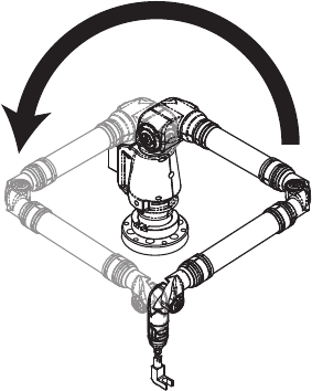
1 Line up front of EDGE base
with the calibration cone.
2 Open up an X, Y, Z DRO in
CAM2 or another
application.
3 Place the probe in the cone
and hold the EDGE very still.
4 Apply approximately five (5)
pounds of force to the base
ring in the direction of the
cone.
5 Note the Y deviation. It
should not exceed 25% of the
EDGE's accuracy.
6 Apply approximately five (5)
pounds of force to the base
ring 90° away from the
previous direction.
7 Note the Y deviation. It
should not exceed 25% of the
EDGE's accuracy.
8 Apply approximately five (5) pounds of force to the cone.
9 Note the X, Y and Z deviations. They should not exceed 25% of the
EDGE's accuracy.
08M52E00_FaroArm_EDGE.book Page 90 Friday, October 1, 2010 11:14 AM
FaroArm®EDGE™ Manual
September 2010 - DRAFT
91
Chapter 6: Maintenance and Troubleshooting
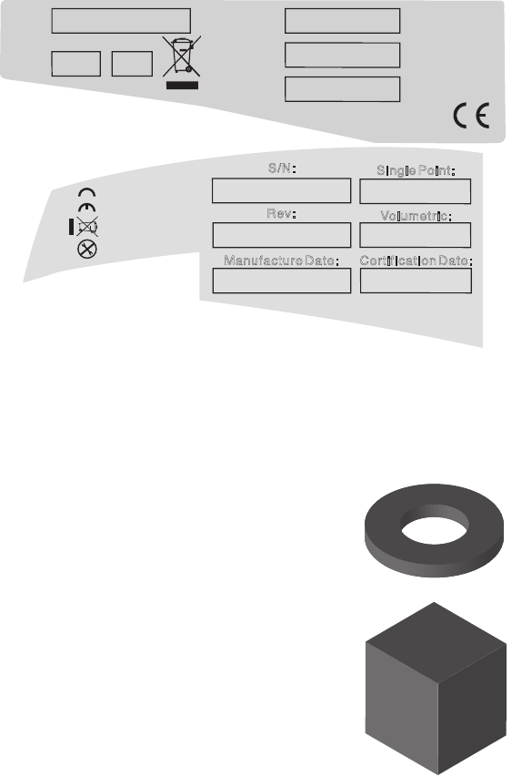
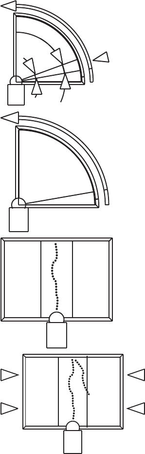
Single Point Articulation Test (SPAT)
Mounting should always be tested prior to a SPAT test. The SPAT test
checks the repeatability of the EDGE's X, Y and Z coordinates
throughout its range of motion.
In CAM2 software, start the SPAT routine from the DIAGNOSTICS
dialog box.
• In CAM2 Measure, run the DEVICES >DIAGNOSTICS command
and click the SINGLE POINT ARTICULATION TEST (SPAT) button in
the DIAGNOSTICS dialog box.
• In CAM2 Q, run the DEVICES >DEVICE CONTROL PANEL
command, click the DIAGNOSTICS button in the FARO DEVICE
CONTROL PANEL. Then click the SINGLE POINT ARTICULATION
TEST (SPAT) button in the DIAGNOSTICS dialog box.
•For more information, see “Diagnostics” on page 114.
Place and hold the calibrated
probe in the calibration cone or
any conical socket.
Start with the elbow of the
EDGE to one side and press the
FRONT button.
Slowly sweep the elbow so that
it ends up on the opposite side.
NOTE: Measurements
automatically record as the
elbow moves.
• In the dialog box, watch the
status bar. Sweep the elbow all
the way to the opposite side.
Slowly sweep the elbow back to the starting side.
• In the dialog box, watch the status bar. Sweep the elbow all the way
back to the starting side.
The SPAT automatically completes. The set of measurements from
each sweep are compared for repeatability. If the sets are not
repeatable, you must repeat the test.
NOTE: The EDGE movement should feel fluid. Be careful not to
stress the EDGE while taking these points or get too close to an end
stop since stresses can be amplified near end stops.
08M52E00_FaroArm_EDGE.book Page 91 Friday, October 1, 2010 11:14 AM
FaroArm®EDGE™ Manual
September 2010 - DRAFT
92
Chapter 6: Maintenance and Troubleshooting
Note the deviations in X, Y, and Z. The (Max-Min)/2, or Single Point
repeatability value, of each coordinate should be lower than the value
printed on the EDGE.
Click the YES button to generate a detailed report of the test, or the
NO button to end the test.
If not using CAM2, simply export your list of points to Microsoft
Excel and calculate (Max.- Min.)/2 for each coordinate.
Calibrated Artifact
Measure an artifact of certified dimensions (i.e.:
ring gage or gage block).
Ring Gage should be measured as a cylinder.
Gage Block should be measured plane-to-
plane, or point-to-plane (surface point).
NOTE: The dimension of calibrated artifacts is
usually specified at a temperature of 20°C
(68°F). If the current temperature is different,
use the Material Temperature Compensation
function in CAM2, or the following formula:
S/NS/N
ModelModel RevRev Single PointSingle Point
VolumetricVolumetric
Certification Certification
DateDate
MADE IN U.S.A.
P08-02-07-05675
P0826.2
Aug18, 2007
+/- .036 mm.
+/- .025 mm.
Q08-05-08-06548
2.2
May 08, 2008May 08, 2008
+/- .028 mm.
+/- .020 mm.
Rev:
MADE IN
U.S.A
S/N:
Volumetric:
Certification Date:Manufacture Date:
Single Point:
08M52E00_FaroArm_EDGE.book Page 92 Friday, October 1, 2010 11:14 AM
FaroArm®EDGE™ Manual
September 2010 - DRAFT
93
Chapter 6: Maintenance and Troubleshooting
Actual Length = Specified Length*(1 + CTE*(Current centigrade
temperature - 20°C)), where CTE is the Coefficient of Thermal
Expansion of the material in ppm/°C.
EXAMPLE: A 150mm ring gage measured at 25°C made of Steel 1020
will be: 150mm * (1 + 11.7e-6/C*(25°C - 20°C)) = 150.00585 mm
If additional support is required, please contact customer support. When
contacting FARO’s Customer Service, please provide the following
information:
1 The serial number of the device(s).
2 A copy of the probe calibration log.
3 A copy of the event log.
4 A copy of the Single Point Articulating Test (SPAT).
5 Pictures of the setup.
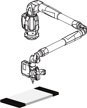
Diagnosing FARO Laser Line Probe Accuracy Problems
Always diagnose the EDGE prior to diagnosing the FARO Laser Line
Probe. If the EDGE is not mounted correctly, or the hard probe is not
accurately calibrated, then the FARO Laser Line Probe will produce
inaccurate results.
Allow the FARO Laser Line Probe to warm-up.
• 60 minutes for version 1
• 30 minutes for version 2
• 15 minutes for version 3
Clean the top and bottom lenses with the cloth from the FARO Laser
Line Probe Case. Dirt and grease on either lens can cause poor results.
08M52E00_FaroArm_EDGE.book Page 93 Friday, October 1, 2010 11:14 AM
FaroArm®EDGE™ Manual
September 2010 - DRAFT
94
Chapter 6: Maintenance and Troubleshooting
Place the FARO Calibration Plate approximate 2/3 of the EDGE's
reach away from its base.
NOTE: Secure the plate firmly to the table. If you are clamping at
more than one location, make sure that the surface is flat so that the
plate does not bend. Clamping only on one end may create a “spring
board” effect.
08M52E00_FaroArm_EDGE.book Page 94 Friday, October 1, 2010 11:14 AM
FaroArm®EDGE™ Manual
September 2010 - DRAFT
95
Chapter 6: Maintenance and Troubleshooting
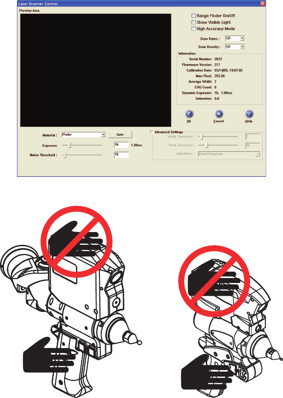
FARO Laser Line Probe Calibration
Ensure the Scan Rate and Scan Density are set 1/1. From the host
application select “Scanner Options” or “Scanner Controls” to access
the settings dialog box.
Perform the calibration at least 3 times. See “Calibration” on
page 47.
08M52E00_FaroArm_EDGE.book Page 95 Friday, October 1, 2010 11:14 AM
FaroArm®EDGE™ Manual
September 2010 - DRAFT
96
Chapter 6: Maintenance and Troubleshooting
NOTE: Never grab the FARO Laser Line Probe while measuring.
Simply hold the EDGE's pistol grip. Holding the FARO Laser Line
Probe can cause inaccuracy due to bending of its mounting bracket.
When sweeping from side to side and front to back, make sure you
sweep through at least 90 degrees.
Typically, you should take about 200 scans during the calibration
process.
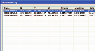
In the probe calibration log, look at the X, Y, Z, A, B, C values. Each
value should repeat to within:
X: 100 microns A: 0.1 degrees
Y: 50 microns B: 0.05 degrees
Z: 50 microns C: 0.1 degrees
NOTE: Values are for V2 FARO Laser Line Probe
If additional support is required, please contact customer support. When
contacting FARO’s Customer Service, please provide the following
information:
1 The serial number of the device(s).
2 A copy of the probe calibration log.
3 A copy of the event log.
4 A copy of the Single Point Articulating Test (SPAT).
5 Pictures of the setup.
08M52E00_FaroArm_EDGE.book Page 96 Friday, October 1, 2010 11:14 AM
FaroArm®EDGE™ Manual
September 2010 - DRAFT
97
Chapter 6: Maintenance and Troubleshooting
08M52E00_FaroArm_EDGE.book Page 97 Friday, October 1, 2010 11:14 AM
FaroArm®EDGE™ Manual
September 2010 - DRAFT
98
Chapter 6: Maintenance and Troubleshooting
08M52E00_FaroArm_EDGE.book Page 98 Friday, October 1, 2010 11:14 AM
FaroArm® Manual
September 2010
81
Chapter 2: Configuring the FaroArm® in CAM2® Measure
Chapter 2: Configuring the FaroArm®
in CAM2® Measure
The DEVICES menu contains all the commands used to
configure a measuring device. These commands are also
available on the Devices toolbar.
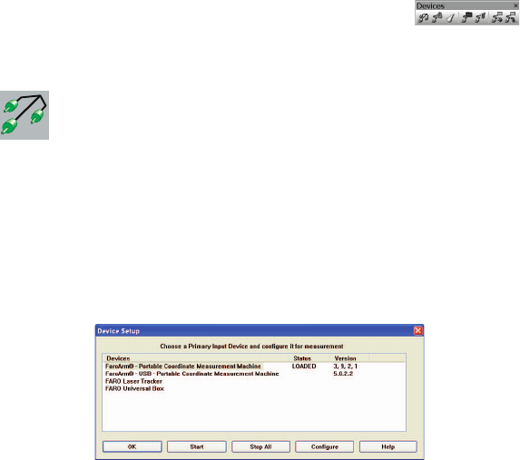
Device Setup
Select DEVICES < DEVICE SETUP from the DEVICES menu.
Choose a primary input device from the DEVICE SETUP dialog box. The
default device is the FaroArm. To change the primary input device,
select the device name and click the START button. This establishes
communication with the selected device.
When the CAM2 Measure starts, the software attempts to initialize
communication with the primary input device.
Figure 2-1 Device Setup dialog box
08M52E00_FaroArm_EDGE.book Page 81 Friday, October 1, 2010 11:14 AM
FaroArm® Manual
September 2010
82
Chapter 2: Configuring the FaroArm® in CAM2® Measure
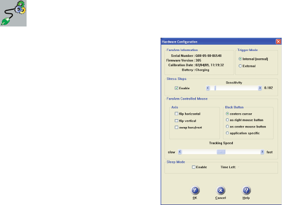
Hardware Configuration
Select DEVICES < HARDWARE
CONFIG from the DEVICES menu. In
the HARDWARE CONFIGURATION dialog
box you can:
• View the current information about
the FaroArm.
• Set the Trigger mode.
• Enable/disable Stress Stops and adjust
the sensitivity. See “Error and Status
Indicators” on page 16.
• Set the arm controlled mouse settings.
• Enable/disable Sleep Mode.
Click OK to accept the changes. Click
the CANCEL button to discard any changes and exit the command.
Stress Stops: The default value is 0.182 and should rarely be set any
lower.
NOTE: For FaroArm Advantage and FARO Digital Template set the
stress stop sensitivity at a maximum of 0.364.
FaroArm Controlled Mouse: The movement of the mouse cursor can
be switched as it relates to the movement of the probe.
Set an option for the device’s BACK button. These options are ignored
during any measurement command.
• Application Specific - sends a special signal to the application
software. The software can use this special signal to launch any
command. For example, this repeats the last command in FARO’s
CAM2 Measure X.
Tracking Speed: Adjust the speed of the cursor is adjusted using the
Tracking Speed slider.
Sleep Mode: The FaroArm shuts down with no activity after two hours.
TIME LEFT is the remaining time before the FaroArm shuts down.
08M52E00_FaroArm_EDGE.book Page 82 Friday, October 1, 2010 11:14 AM
FaroArm® Manual
September 2010
83
Chapter 2: Configuring the FaroArm® in CAM2® Measure
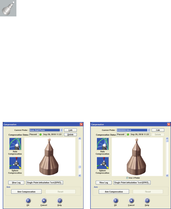
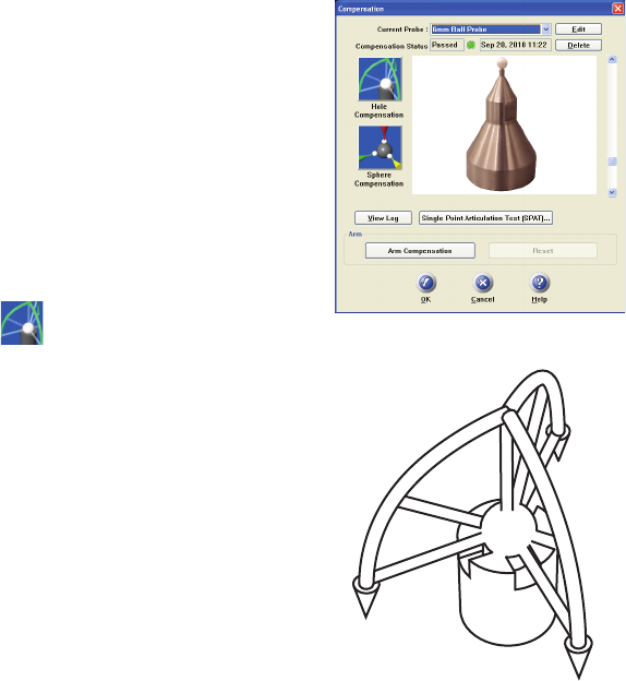
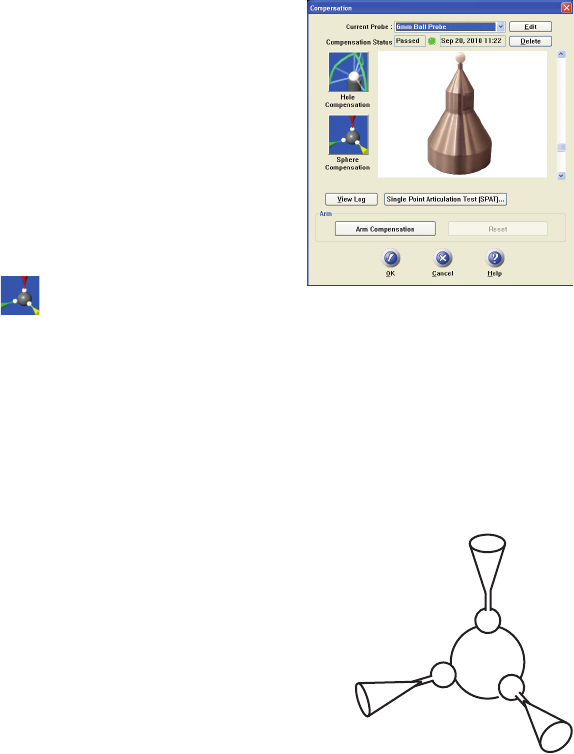
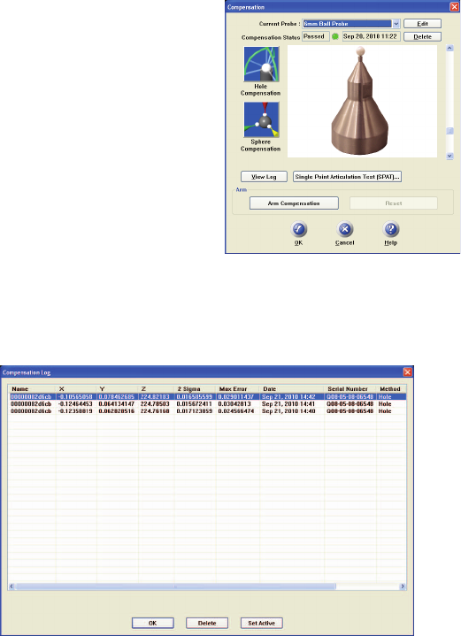
Probes
Select DEVICES < PROBES from the DEVICES menu. In the
COMPENSATION dialog box you can:
• Select the current probe and view the COMPENSATION STATUS.
• Create, Edit and Delete a probe.
• Compensate the current probe.
• View the compensation log for the current probe.
• Enable or disable the use of FARO i-Probes with the
FaroArmQuantum.
• Start the Single Point Articulation Test (SPAT).
• Run a Arm Compensation or reset to the FARO Factory Arm
Compensation.
The COMPENSATION STATUS and compensation date are displayed for
every probe. The four standard probes for the FaroArm (3mm, 6mm,
Point and FARO Laser Line Probe) are created by default. Compensate
each of these probes before you begin measuring your parts.
Click the PERFORM SINGLE POINT ARTICULATION TEST (SPAT)
button to run a Single Point Articulation Test (SPAT) with your
FaroArm. You can save this report to a file which you can send to
FARO’s Customer Service Department. For more information, see
“Single Point Articulation Test (SPAT)” on page 73.
Figure 2-2 FaroArm Platinum/Fusion
Compensation dialog box
Figure 2-3 FaroArm Quantum
Compensation dialog box
08M52E00_FaroArm_EDGE.book Page 83 Friday, October 1, 2010 11:14 AM
FaroArm® Manual
September 2010
84
Chapter 2: Configuring the FaroArm® in CAM2® Measure
Click the ARM COMPENSATION button to create a user arm
compensation for your FaroArm. For more information, see “User
Compensation” on page 75.
Using FARO i-Probes
When a FARO i-Probe is attached to a FaroArm Quantum, it is
automatically added to the CURRENT PROBE list. You do not need to edit
any parameters of the FARO i-Probe.
NOTE: FARO i-Probes will not attach to FaroArm Platinum or
Fusion. Installing the i-Probe to anything other than a FaroArm
Quantum damages the i-Probe.
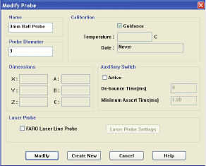
Edit Probe
Click the EDIT button in the COMPENSATION dialog box to modify the
details of the current probe. Change any settings and click the MODIFY
button to continue.
To create a new probe:
1 Enter a new Name for the probe.
2 Enter the diameter of the probe. Check the status bar at the bottom
of your screen for the current units.
3 Select the AUXILIARY SWITCH check box, and enter a De-bounce
Time if necessary.
4 Select the GUIDANCE check box to use the guidance feature in hole
compensation. See “Hole Method - Guidance” on page 86, and
“Hole Method” on page 89.
Figure 2-4 Modify Probe dialog box
08M52E00_FaroArm_EDGE.book Page 84 Friday, October 1, 2010 11:14 AM
FaroArm® Manual
September 2010
85
Chapter 2: Configuring the FaroArm® in CAM2® Measure
5 Click the CREATE NEW button.
The new probe is now current. You must compensate the new probe.
Probe Compensation Overview
Probe compensation is a localized process by which a measurement
device is optimized to perform measurements accurately.
To understand probe compensation, you must first understand the
FaroArm's reference system. The FaroArm is factory compensated from
the base to the last joint or axis, and the position of this joint is defined
by the coordinate system which originates at the base of the FaroArm.
The last axis of the FaroArm has its own coordinate system, and the
location of the center of the ball probe is reported in the probe's
coordinate system. After the probe's coordinates are established, these
are translated into FaroArm coordinates and you are ready to start taking
measurements.
Measurement accuracy relies on probe compensation under optimal
conditions. If the probe compensation passes, measurements will be
accurate. If the probe compensation fails, measurements will not be as
accurate. Proper mounting and technique are critical compensation
factors.
To optimize compensation and minimize
stress-induced errors during this critical
procedure, place the FaroArm in a single
position in which the elbow joint
remains relatively stationary without any
obstructions or restrictions in movement
while the compensation is performed.
Do not let the elbow joint fall during
compensation. Only exercise the last
joint of the FaroArm for the software to
accurately compensate the probe tip.
Minimizing elbow joint movement and
focusing on the probe and last arm joint
during compensation maximizes
measurement accuracy.
08M52E00_FaroArm_EDGE.book Page 85 Friday, October 1, 2010 11:14 AM
FaroArm® Manual
September 2010
86
Chapter 2: Configuring the FaroArm® in CAM2® Measure
Compensate Probe
When changing the style or dimension of the probe at the end of the
FaroArm, you must compensate it for the FaroArm to measure and
function accurately. Probe compensation is an optimization procedure
that requires you to digitize points. The two methods of compensation
are:
•Hole
• Sphere
Click either button to compensate the current probe. The Hole
Compensation method differs depending on whether the GUIDANCE
check box is selected or cleared. See “Edit Probe” on page 84.
•See “Hole Method - Guidance” on page 86.
•See “Hole Method” on page 89.
•See “Sphere Method” on page 91.
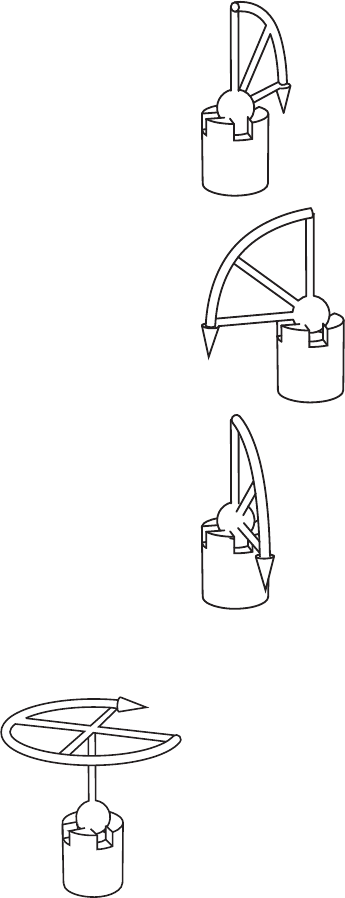
Hole Method - Guidance
Perform the Hole compensation using the FARO probe compensation
cone. If the GUIDANCE check box is selected for the current probe, use
the following steps. See “Edit Probe” on page 84.
Collect all of the points in this method by holding down the FRONT
button. The FaroArm will collect points as fast as possible (“scanning”)
Figure 2-5 Hole Method
Position #1
Position #2
Position #3
08M52E00_FaroArm_EDGE.book Page 86 Friday, October 1, 2010 11:14 AM
FaroArm® Manual
September 2010
87
Chapter 2: Configuring the FaroArm® in CAM2® Measure
until you release the FRONT button. Digitize at least 200 points in each
of the three different positions.
1 Place the ball probe in the
cone.
2 Seat the probe in the cone,
move the handle down until
the shaft of the probe is
parallel with the top of the
cone.
• Look at the dialog box and
move the handle until you
reach the starting position.
3 Press and hold the FRONT
button. Sweep the handle up
to the vertical position,
making sure to move in a
straight line. Be sure that the
ball probe remains seated in
the hole.
• Release the FRONT
button to pause.
• Look at the dialog box to
help you stay within the
zone.
4 Sweep again until all 200
points are digitized. Look at
the dialog box to help you
digitize all of the points.
08M52E00_FaroArm_EDGE.book Page 87 Friday, October 1, 2010 11:14 AM
FaroArm® Manual
September 2010
88
Chapter 2: Configuring the FaroArm® in CAM2® Measure
NOTE: Seven-axis FaroArms have an additional position. Rotate the
handle.
CAUTION: The probe must be well-seated in the hole when
digitizing all compensation points. Even one or two poorly digitized
points significantly affects the optimization process, which then has
an effect on the accuracy of the FaroArm.
5 Rotate the Probe to the next
position. Look at the dialog
box and move the handle
until you reach the start of
the next position.
• Repeat steps 1 through 4
and digitize 200 more
points in this position.
6 Rotate the Probe to the last
position. Look at the dialog
box and move the handle
until you reach the start of
the next position.
• Repeat steps 1 through 4
and digitize 200 more
points in this position.
Figure 2-6 Additional Position for Seven-axis FaroArms
08M52E00_FaroArm_EDGE.book Page 88 Friday, October 1, 2010 11:14 AM
FaroArm® Manual
September 2010
89
Chapter 2: Configuring the FaroArm® in CAM2® Measure
The digitized compensation points
then calculate and the
COMPENSATION STATUS updates. If
the probe passes, the current date and
time is added to the probe
information.
You can view the details for all of the
compensations of a probe by clicking
the VIEW LOG button. See “View
Log” on page 95.
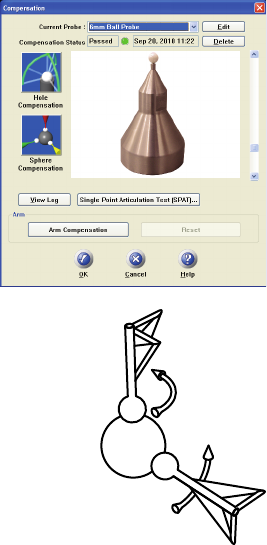
Hole Method
Perform the Hole compensation using
the FARO probe compensation cone or
a 5mm diameter machine drilled hole.
The hole does not have to be exactly
5mm, but it must be smaller than the
probe’s diameter with a smooth seat. If
the GUIDANCE check box is clear for
the current probe, use the following
steps. See “Edit Probe” on page 84.
Collect all of the points in this method
by holding down the FRONT button.
The FaroArm will collect points as fast
as possible (“scanning”) until you release the FRONT button.
1 Place the ball probe in the hole. Start in a vertical position.
2 Press and hold the FRONT button. Sweep the handle down to one
of the horizontal positions. Be sure that the ball probe remains
seated in the hole.
3 Release the FRONT button and repeat for each position.
Position #1
Position #2
Position #3
08M52E00_FaroArm_EDGE.book Page 89 Friday, October 1, 2010 11:14 AM
FaroArm® Manual
September 2010
90
Chapter 2: Configuring the FaroArm® in CAM2® Measure
NOTE: Seven-axis FaroArms have an additional position. Rotate the
handle.
CAUTION: The probe must be well-seated in the hole when
digitizing all compensation points. Even one or two poorly digitized
• Digitize points in the hole and sweep to
position #1.
• Digitize points in the hole and sweep to
position #2.
• Digitize points in the hole and sweep to
position #3.
Figure 2-7 Hole Method - Guidance
Figure 2-8 Additional Position for Seven-axis FaroArms
08M52E00_FaroArm_EDGE.book Page 90 Friday, October 1, 2010 11:14 AM
FaroArm® Manual
September 2010
91
Chapter 2: Configuring the FaroArm® in CAM2® Measure
points significantly affects the optimization process, which then has
an effect on the accuracy of the FaroArm.
The digitized compensation points
then calculate and the
COMPENSATION STATUS updates. If
the probe passes, the current date and
time is added to the probe
information.
You can view the details for all of the
compensations of a probe by clicking
the View Log button. See “View Log”
on page 95.
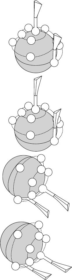
Sphere Method
Perform the Sphere compensation using any size precision sphere or
tooling ball. The sphere should be at least 10mm (3/8”) diameter or
larger. The Sphere compensation method differs slightly for Six-Axis
FaroArms or Seven-Axis FaroArms. See “Six-Axis FaroArm” on
page 91 or “Seven-Axis FaroArm” on page 93.
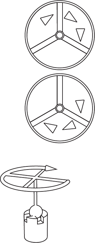
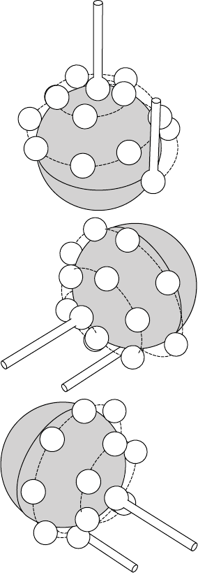
Six-Axis FaroArm
You will digitize 45 individual points in
specific locations around the sphere by
pressing the FRONT button for each.
CAUTION: The ball probe must remain
in contact with the sphere while digitizing
points. Even one or two poorly digitized
points significantly affects the
optimization process, which then has an
effect on the accuracy of the FaroArm.
Position #1
Position #2
Position #3
08M52E00_FaroArm_EDGE.book Page 91 Friday, October 1, 2010 11:14 AM
FaroArm® Manual
September 2010
92
Chapter 2: Configuring the FaroArm® in CAM2® Measure
• Digitize 15 points around the
top hemisphere of the sphere
with the probe pointing in
position #1.
• Digitize 15 points around the
front hemisphere of the sphere
with the probe pointing in
position #2.
• Digitize 15 points around the
side hemisphere of the sphere
with the probe pointing in
position #3.
1
2
8
13
12
11 10
9
7
6
5
15 14
15
14
12
11 10
9
8
2
3
4
5
6
15
13
12
11 10
3
4
5
6
78
08M52E00_FaroArm_EDGE.book Page 92 Friday, October 1, 2010 11:14 AM
FaroArm® Manual
September 2010
93
Chapter 2: Configuring the FaroArm® in CAM2® Measure
The digitized compensation points
then calculate and the
COMPENSATION STATUS updates. If
the probe passes, the current date and
time is added to the probe
information.
You can view the details for all of the
compensations of a probe by clicking
the View Log button. See “View Log”
on page 95.
Seven-Axis FaroArm
You will digitize 44 individual points in specific
locations around the sphere by pressing the
FRONT button for each.
CAUTION: The ball probe must remain in
contact with the sphere while digitizing points.
Even one or two poorly digitized points
significantly affects the optimization process,
which then has an effect on the accuracy of the
FaroArm.
Position #1
Position #2
08M52E00_FaroArm_EDGE.book Page 93 Friday, October 1, 2010 11:14 AM
FaroArm® Manual
September 2010
94
Chapter 2: Configuring the FaroArm® in CAM2® Measure
• Digitize 11 points around the
top hemisphere of the sphere
with the probe pointing in
position #1. Hold the handle in
the same direction and
orientation for every point.
• Rotate the handle 90 degrees.
Digitize 11 points around the
top hemisphere of the sphere
with the probe pointing in
position #1. Hold the handle in
the same direction and
orientation for every point.
• Digitize 11 points around the
front hemisphere of the sphere
with the probe pointing in
position #2. Hold the handle in
the same direction and
orientation for every point.
• Rotate probe 90 degrees.
Digitize 11 points around the
front hemisphere of the sphere
with the probe pointing in
position #2. Hold the handle in
the same direction and
orientation for every point.
1
2
4
5
9
10
87
11
1
2
7
8
9
10
4
5
11
3
4
5
11
10
9
87
5
10
11
7
3
8
9
4
08M52E00_FaroArm_EDGE.book Page 94 Friday, October 1, 2010 11:14 AM
FaroArm® Manual
September 2010
95
Chapter 2: Configuring the FaroArm® in CAM2® Measure
The digitized compensation points
then calculate and the
COMPENSATION STATUS updates. If
the probe passes, the current date and
time is added to the probe
information.
You can view the details for all of the
compensations of a probe by clicking
the View Log button. See “View
Log” on page 95.
View Log
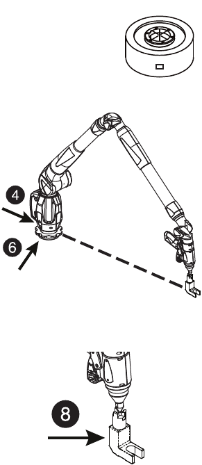
The COMPENSATION LOG dialog box displays the compensation history
of the current probe. You can set to active or delete any previous
compensation. You can also select the compensation values and copy
them to the windows clipboard.
• The X, Y, Z values are the location of the center of the ball probe in
the last joint coordinate system.
• The 2 Sigma value is the deviation of all the points taken during the
compensation.
• The Max. Error column displays the displacement of the point with
the largest displacement. In order to pass compensation, this value has
to be less than the single point accuracy specification of the arm. See
“FaroArm Performance” on page 51.
Figure 2-9 Compensation Log dialog box
08M52E00_FaroArm_EDGE.book Page 95 Friday, October 1, 2010 11:14 AM
FaroArm® Manual
September 2010
96
Chapter 2: Configuring the FaroArm® in CAM2® Measure
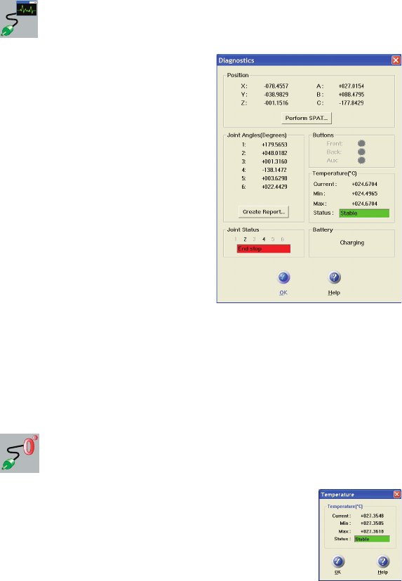
Diagnostics
Select DEVICES < DIAGNOSTICS
from the DEVICES menu. The
DIAGNOSTICS dialog box displays:
• X, Y, Z Machine Coordinates.
• Encoder angles for each joint of the
FaroArm.
• FRONT and BACK button, and
Auxiliary Port operations.
• The Temperature of the FaroArm’s
internal sensor.
• The Joint Status of each joint of the
FaroArm which also includes the
encoder end stop warnings.
• The status of the FaroArm battery.
Click the PERFORM SINGLE POINT ARTICULATION TEST (SPAT)
button to run a Single Point Articulation Test (SPAT) with your
FaroArm. You can save this report to a file which you can send to
FARO’s Customer Service Department. For more information, see
“Single Point Articulation Test (SPAT)” on page 73.
Temperature
Select DEVICES < TEMPERATURE from the
DEVICES menu. This command displays the current
temperature of the FaroArm and the elapsed time of the
temperature sampling.
Because different components heat up or cool down at
different rates, the FaroArm must be at a steady state
temperature (within ±3° Celsius for five minutes) before measuring with
the device.
08M52E00_FaroArm_EDGE.book Page 96 Friday, October 1, 2010 11:14 AM
FaroArm® Manual
September 2010
97
Chapter 3: Configuring the FaroArm® in CAM2® Q
Chapter 3: Configuring the FaroArm®
in CAM2® Q
The DEVICE CONTROL panel contains all the commands for configuring
a measuring device. In CAM2 Q choose DEVICE < DEVICE
CONTROL PANEL to show the panel. You can also press the P hot key
on the keyboard.
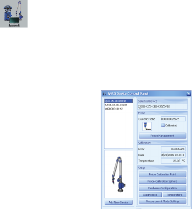
Device Control Panel
The DEVICE CONTROL panel appears when CAM2 Q is launched, and
contains a list of all active (detected) devices. The DEVICE CONTROL
panel contains a list of all active devices with the properties of each
associated device. You can also press the P hot key on the keyboard.
Choose a FaroArm from the list to see the probe details.
• Click the >> button to hide the list of devices.
• Click the << button to show the list of devices.
Add a Device
From the DEVICE CONTROL panel, click the ADD NEW DEVICE
button. Select an eligible device from the ADD NEW DEVICE dialog and
click CONNECT.
Figure 3-1 Device Control Panel
08M52E00_FaroArm_EDGE.book Page 97 Friday, October 1, 2010 11:14 AM
FaroArm® Manual
September 2010
98
Chapter 3: Configuring the FaroArm® in CAM2® Q
Change Probe
From the DEVICE CONTROL panel, click the PROBE MANAGEMENT
button to show the COMPENSATION dialog box. For more information,
see “Probes” on page 83.
Hole Compensation
From the DEVICE CONTROL panel, click the PROBE COMPENSATION
POINT button to compensate the probe. For more information, see
“Hole Method” on page 89.
Sphere Compensation
From the DEVICE CONTROL panel, click the PROBE COMPENSATION
SPHERE button to compensate the probe. For more information, see
“Sphere Method” on page 91.
Hardware Configuration
From the DEVICE CONTROL panel, click the HARDWARE
CONFIGURATION button to change the setup of the FaroArm. For
more information, see “Hardware Configuration” on page 82.
Diagnostics
From the DEVICE CONTROL panel, click the DIAGNOSTICS button to
show the FaroArm DIAGNOSTICS dialog box. For more information, see
“Diagnostics” on page 96.
Temperature
From the DEVICE CONTROL panel, click the TEMPERATURE button to
show the TEMPERATURE dialog box. For more information, see
“Temperature” on page 96.
Measurement Mode Setting
From the DEVICE CONTROL panel, click the MEASUREMENT MODE
SETTING button to set the default collection mode in the MODE drop-
down window of the MEASUREMENT WINDOW for this device.
08M52E00_FaroArm_EDGE.book Page 98 Friday, October 1, 2010 11:14 AM
FaroArm® Manual
September 2010
99
Chapter 3: Configuring the FaroArm® in CAM2® Q
NOTE: The MEASUREMENT WINDOW appears when the CAM2 Q
ADD READINGS command is started, or when any measure feature
command is started in MEASURE NOW mode.
In the MODE SETTINGS dialog:
•Single Point: press the FRONT button, or the G key, to collect a
single reading.
•Distance Interval: press the FRONT button, or the G key, to start
the distance interval. Collect a single reading when the probe
moves a distance. Choose this radio button, enter the distance value
and press OK.
•Time Interval: press the FRONT button, or the G key, to start the
time interval. Collect a single reading over time. Choose this radio
button, enter the time value and press OK.
08M52E00_FaroArm_EDGE.book Page 99 Friday, October 1, 2010 11:14 AM
08M52E00_FaroArm_EDGE.book Page 100 Friday, October 1, 2010 11:14 AM
43
Technical Support
FARO Technologies, Inc. is committed to providing the best technical
support to our customers. Our Service Policy is detailed in Appendix C:
Industrial Products Service Policy of this manual. If you have any
problem using one of our products, please follow these steps before
contacting our Technical Support Team:
• Be sure to read the relevant sections of the documentation to find the
help you need.
• Visit the FARO Customer Care area on the Web at www.faro.com to
search our technical support database. This is available 24 hours a day
7 days a week.
• Document the problem you are experiencing. Be as specific as you
can. The more information you have, the easier the problem will be to
solve.
• If you still cannot resolve your problem, have your device’s Serial
Number available before calling.
Support Hours (Monday through Friday)
North America:
8:00 a.m. to 8:00 p.m. Eastern Standard Time (EST).
Europe:
8:00 a.m. to 5:00 p.m. Central European Standard Time (CET).
Asia:
8:30 a.m. to 5:30 p.m. Singapore Standard Time (SST).
Japan:
9:00 a.m. to 5:00 p.m. Japan Standard Time (JST).
China:
8:30 a.m. to 5:30 p.m. China Standard Time (CST).
India:
9:30 a.m. to 5:30 p.m. India Standard Time (IST).
You can also e-mail or fax any problems or questions 24 hours a day.
•Phone
North America:
800 736 2771, +1 407 333 3182 (Worldwide)
Europe:
+800 3276 7378, +49 7150 9797-400 (Worldwide)
08M52E00_FaroArm_EDGE.book Page 43 Friday, October 1, 2010 11:14 AM
44
Asia:
1800 511 1360, +65 6511 1350 (Worldwide)
Japan:
+800 6511 1360, +81 561 63 1411 (Worldwide)
China:
+800 6511 1360, +86 21 6191 7600 (Worldwide)
India:
000800 650 1397, +91 11 4167 6330/1 (Worldwide)
•Fax
North America:
+1 407 333 8056
Europe:
+800 3276 1737, +49 7150 9797-9400 (Worldwide)
Asia:
+65 6543 0111
Japan:
+81 561 63 1412
China:
+86 21 6494 8670
India:
+91 11 4167 6332
•E-Mail
North America:
support@faro.com
Europe:
support@faroeurope.com
Asia:
salesap@faro.com
Japan:
support_japan@faro.com
China:
chinainfo@faro.com
India:
infoindia@faro.com
08M52E00_FaroArm_EDGE.book Page 44 Friday, October 1, 2010 11:14 AM
45
E-Mails or Faxes sent outside regular working hours usually are
answered before 12:00 p.m. the next working day. Should our staff be
on other calls, please leave a voice mail message; calls are always
returned within 4 hours. Please remember to leave a detailed description
of your question and your device’s Serial Number. Do not forget to
include your name, fax number, telephone number and extension so we
can reach you promptly.
08M52E00_FaroArm_EDGE.book Page 45 Friday, October 1, 2010 11:14 AM
08M52E00_FaroArm_EDGE.book Page 46 Friday, October 1, 2010 11:14 AM
A-1
Appendix A: Software License
Agreement
This Software License Agreement is part of the Operating Manual for
the product and software System which you have purchased from FARO
TECHNOLOGIES, INC. (collectively, the “Licenser”) By your use of
the software you are agreeing to the terms and conditions of this
Software License Agreement. Throughout this Software License
Agreement, the term “Licensee” means the owner of the System.
I. The Licenser hereby grants the Licensee the non-exclusive right to
use the computer software described in this Operating Manual (the
“software”). The Licensee shall have no right to sell, assign, sub-
license, rent or lease the software to any third party without the
Licenser’s prior written consent.
II. The Licenser further grants the Licensee the right to make a backup
copy of the software media. The Licensee agrees that it will not
decompile, disassemble, reverse engineer, copy, transfer, or otherwise
use the software except as permitted by this section. The Licensee
further agrees not to copy any written materials accompanying the
software.
III. The Licensee is licensed to use the Software only in the manner
described in the Operating Manual. Use of the Software in a manner
other than that described in the Operating Manual or use of the software
in conjunction with any non-Licenser product which decompiles or
recompiles the software or in any other way modifies the structure,
sequence or function of the software code, is not an authorized use, and
further, such use voids the Licenser’s set forth below.
IV. The only warranty with respect to the software and the
accompanying written materials is the warranty, if any, set forth in the
Quotation/Purchase Order and Appendix B: Purchase Conditions
pursuant to which the software was purchased from the Licenser.
V. THIS WARRANTY IS IN LIEU OF OTHER WARRANTIES,
EXPRESS OR IMPLIED, INCLUDING, BUT NOT LIMITED TO,
THE IMPLIED WARRANTIES OF MERCHANTABILITY AND
FITNESS FOR A PARTICULAR PURPOSE WITH RESPECT TO
THE SOFTWARE AND WRITTEN MATERIALS. IN NO EVENT
08M52E00_FaroArm_EDGE.book Page 1 Friday, October 1, 2010 11:14 AM
A-2
WILL THE LICENSER BE LIABLE FOR DAMAGES, INCLUDING
ANY LOST PROFITS OR OTHER INCIDENTAL OR
CONSEQUENTIAL DAMAGES ARISING OUT OF THE USE OR
INABILITY TO USE THE SOFTWARE, NOTWITHSTANDING
THAT THE LICENSER HAVE BEEN ADVISED OF THE
POSSIBILITY OF SUCH DAMAGES, THE LICENSER WILL NOT
BE LIABLE FOR ANY SUCH CLAIM BY ANY OTHER PARTY.
VI. In the event of any breach by the Licensee of this Agreement, the
license granted hereby shall immediately terminate and the Licensee
shall return the software media and all written materials, together with
any copy of such media or materials, and the Licensee shall keep no
copies of such items.
VII.The interpretation of this Agreement shall be governed by the
following provisions:
A. This Agreement shall be construed pursuant to and governed by
the substantive laws of the State of Florida (and any provision of
Florida law shall not apply if the law of a state or jurisdiction other
than Florida would otherwise apply).
B. If any provision of this Agreement is determined by a court of
competent jurisdiction to be void and non-enforceable, such
determination shall not affect any other provision of this Agreement,
and the remaining provisions of this Agreement shall remain in full
force and effect. If any provision or term of this Agreement is
susceptible to two or more constructions or interpretations, one or
more of which would render the provision or term void or non-
enforceable, the parties agree that a construction or interpretation
which renders the term of provision valid shall be favored.
C. This Agreement constitutes the entire Agreement, and supersedes
all prior agreements and understandings, oral and written, among the
parties to this Agreement with respect to the subject matter hereof.
VIII.If a party engages the services of an attorney or any other third
party or in any way initiates legal action to enforce its rights under this
Agreement, the prevailing party shall be entitled to recover all
reasonable costs and expenses (including reasonable attorney’s fees
before trial and in appellate proceedings).
08M52E00_FaroArm_EDGE.book Page 2 Friday, October 1, 2010 11:14 AM
B-1
Appendix B: Purchase Conditions
All Purchase Orders (hereafter, the “Order”) for FARO-provided
products and services (hereafter, the “Product”) are subject to the
following terms and conditions, which are agreed to by the Purchaser.
All capitalized terms are defined in Section 8.00 Definitions hereafter.
1.00Payment of Purchase Price
1.01Purchaser hereby promises to pay to the order of FARO all deferred
portions of the Purchase Price, together with interest on late purchase
price payments payable at 1.5% per month (18% per annum).
1.02The Purchaser grants to FARO a security interest in the products
sold pursuant to the Order, which may be perfected by UCC-1
Financing Statements to be recorded in the applicable County of the
Purchaser’s business location and filed with the Secretary of State’s
Office, which security interest will remain in effect until payment in full
of the purchase price together with interest on late purchase price
payments payable thereon had been received by FARO.
1.03If the Purchaser fails to make full payment of the purchase price
within the period set out in the Order, FARO shall at its option have the
following remedies, which shall be cumulative and not alternative:
a) the right to cancel the Order and enter the Purchaser’s premises to
re-take possession of the Product, in which event the Purchaser agrees
that any down-payment or deposit shall be forfeited to FARO, as
liquidated damages and not as a penalty, and all costs incurred by
FARO in connection with the removal and subsequent transportation
of the Product shall be payable by the Purchaser upon written
demand;
b) the right to enter the Purchaser’s premises and remove any
Software, components of the Product or other items necessary in
order to render the Product inoperative;
c) the right to withhold all services which would otherwise be
required to be provided by FARO pursuant to the Warranties set out in
Section 4.00 Warranties and Limitation of Liability hereof;
d) terminate any existing software license agreement and
08M52E00_FaroArm_EDGE.book Page 1 Friday, October 1, 2010 11:14 AM
B-2
e) pursue any other available remedy, including suing to collect any
remaining balance of the purchase price (i.e., accelerate the payment
of the purchase price causing the entire balance to immediately
become due and payable in full).
f) Customer will be charged a 20% restocking fee for refusal to accept
equipment as delivered. Equipment must be returned unopened within
10 business days of receipt at customer facility.
1.04If Purchaser fails to make payment(s) in accordance with the terms
of this Order, the Purchaser’s Products may be rendered inoperable until
such payment terms are met.
No waiver by FARO of its rights under these conditions shall be deemed
to constitute a waiver of subsequent breaches or defaults by the
Purchaser. In the event more than one Product is being purchased
pursuant to the Order, unless otherwise set forth herein, each payment
received by FARO from Purchaser shall be applied pro rata against the
cost of each product rather than being applied to the purchase price of
any product.
2.00Delivery and Transportation
2.01Delivery dates are estimates and not guarantees, and are based upon
conditions at the time such estimate is given.
2.02FARO shall not be liable for any loss or damage, whether direct,
indirect or consequential, resulting from late delivery of the Product.
The Purchaser’s sole remedy, if the Product is not delivered within 90
days of the estimated delivery date, shall be to cancel the Order and to
recover from FARO without interest or penalty, the amount of the down-
payment or deposit and any other part of the purchase price which has
been paid by the Purchaser. Notwithstanding the foregoing, such right of
cancellation shall not extend to situations where late delivery is
occasioned by causes beyond FARO’s control, including, without
limitation, compliance with any rules, regulations, orders or instructions
of any federal, state, county, municipal or other government or any
department or agency thereof, force majuere, acts or omissions of the
Purchaser, acts of civil or military authorities, embargoes, war or
insurrection, labor interruption through strike or walkout, transportation
delays and other inability resulting from causes beyond FARO’s control
to obtain necessary labor, manufacturing facilities or materials from its
usual sources. Any delays resulting from such causes shall extend
estimated delivery dates by the length of such delay.
08M52E00_FaroArm_EDGE.book Page 2 Friday, October 1, 2010 11:14 AM
B-3
2.03Responsibility for all costs and risks in any way connected with the
storage, transportation and installation of the Product shall be borne
entirely by the Purchaser. If any disagreement arises as to whether or not
damage to the Product was in fact caused in storage, transit or on
installation, the opinion of FARO’s technical advisors, acting
reasonably, shall be conclusive.
3.00Installation and Operator Training
3.01The Purchaser shall be responsible for installation of the Product,
including, without limitation, the preparation of its premises, the
uncrating of the Product and setting up of the Product for operation.
Purchaser may elect to order contract services from FARO to perform
this service should they elect to do so.
4.00Warranties and Limitation of Liability
4.01FARO warrants that (subject to Section 4.06), the Product shall be
free from defects in workmanship or material affecting the fitness of the
Product for its usual purpose under normal conditions of use, service
and maintenance. A complete statement of FARO’s maintenance/
warranty service is set forth in Appendix B: Purchase Conditions.
4.02FARO warrants that the Software shall operate according to
specifications and the System shall operate and perform in the manner
contemplated in connection with the usual purpose for which it is
designed.
4.03The maintenance/warranty set out in paragraphs 4.01 shall expire at
the end of the twelve (12) month period commencing on the date of
shipment from the FARO factory (the “Maintenance/Warranty Period”).
4.04Subject to the limitations contained in Section 4.06, the Warranties
shall apply to any defects found by the Purchaser in the operation of the
FaroArm and reported to FARO within the Maintenance/Warranty
Period. If the FaroArm or the Software is found by FARO, acting
reasonably, to be defective, and if the defect is acknowledged by FARO
to be the result of FARO’s faulty material or workmanship, the FaroArm
will be repaired or adjusted to the extent found by FARO to be
necessary or at the option of FARO, replaced with a new FaroArm or
parts thereof at no cost to the Purchaser.
4.05Claims under the Warranties shall be made by delivering written
notice to FARO of the defect in the System, the FaroArm. Within a
08M52E00_FaroArm_EDGE.book Page 3 Friday, October 1, 2010 11:14 AM
B-4
reasonable time of receipt of such notice, FARO shall have the System
and FaroArm diagnosed by its service personnel, and maintenance/
warranty service will be provided at no cost to the Purchaser if the
System and FaroArm is found by FARO to be defective within the
meaning of this Section.
(If, in the reasonable opinion of FARO after diagnosis of the system and
the FaroArm are not defective, the Purchaser shall pay the cost of
service, which shall be the amount that FARO would otherwise charge
for an evaluation under a non-warranty service evaluation.
4.06The Warranties do not apply to:
a) Any defects in any component of a System where, if in the
reasonable opinion of FARO, the FaroArm, Software or System has
been improperly stored, installed, operated, or maintained, or if
Purchaser has permitted unauthorized modifications, additions,
adjustments and/or repair to any hard drive structure or content, or
any other part of the System, or which might affect the System, or
defects caused or repairs required as a result of causes external to
FARO workmanship or the materials used by FARO. As used herein,
“unauthorized” means that which has not been approved and
permitted by FARO.
b) The Warranties shall not cover replacement of expendable items,
including, but not limited to, fuses, diskettes, printer paper, printer
ink, printing heads, disk cleaning materials, or similar items.
c) The Warranties shall not cover minor preventive and corrective
maintenance, including, but not limited to, replacement of fuses, disk
drive head cleaning, fan filter cleaning and system clock battery
replacement.
d) Any equipment or its components which was sold or transferred to
any party other than the original Purchaser without the expressed
written consent of FARO.
4.07Factory Repairs
a) IF SYSTEM IS UNDER MAINTANENCE/WARRANTY: The
Purchaser agrees to ship the Product to FARO in the original packing
containers. FARO will return the repaired or replacement Product.
FARO will incur the expense of the needed part and all return
08M52E00_FaroArm_EDGE.book Page 4 Friday, October 1, 2010 11:14 AM
B-5
shipping charges to the Purchaser. FARO may authorize the
manufacturer of a component of the Product to perform the service.
b) IF SYSTEM IS UNDER PREMIUM SERVICE PLAN: When
practical and subject to availability, FARO will make available to the
Purchaser substitute component parts or FaroArm’s (“Temporary
Replacements”) while corresponding parts of the Purchaser’s system
or FaroArm are undergoing repair at FARO’s factory. Shipping
charges for these “Temporary Replacement” parts or FaroArm’s will
be the responsibility of FARO.
c) IF SYSTEM IS NOT UNDER MAINTANENCE/WARRANTY:
The Purchaser is responsible for the cost of the replacement part or
software, and all shipping charges. All charges shall be estimated and
prepaid prior to commencement of repairs.
4.08Nothing herein contained shall be construed as obligating FARO to
make service, parts, or repairs for any product available after the
expiration of the Maintenance/Warranty Period.
4.09Limitation of Liability
FARO shall not be responsible under any circumstances for special,
incidental or consequential damages, including, but not limited to,
injury to or death of any operator or other person, damage or loss
resulting from inability to use the System, increased operating costs,
loss of production, loss of anticipated profits, damage to property, or
other special, incidental or consequential damages of any nature arising
from any cause whatsoever whether based in contract, tort (including
negligence), or any other theory of law. FARO’s only liability
hereunder, arising from any cause whatsoever, whether based in
contract, tort (including negligence) or any other theory of law, consists
of the obligation to repair or replace defective components in the
System or FaroArm subject to the limitations set out above in this
section.
This disclaimer of liability for consequential damage extends to any
such special, incidental or consequential damages which may be
suffered by third parties, either caused directly or indirectly resulting
from test results or data produced by the system or any component
thereof and the Purchaser agrees to indemnify and save FARO harmless
from any such claims made by third parties.
4.10The foregoing shall be FARO’s sole and exclusive liability and the
Purchaser’s sole and exclusive remedy with respect to the system.
08M52E00_FaroArm_EDGE.book Page 5 Friday, October 1, 2010 11:14 AM
B-6
THE SOLE RESPONSIBILITY OF FARO UNDER THE
WARRANTIES IS STATED HEREIN AND FARO SHALL NOT BE
LIABLE FOR CONSEQUENTIAL, INDIRECT, OR INCIDENTAL
DAMAGES, WHETHER THE CLAIM IS FOR BREACH OF
WARRANTY, NEGLIGENCE, OR OTHERWISE.
OTHER THAN THE EXPRESS WARRANTIES HEREIN STATED,
FARO DISCLAIMS ALL WARRANTIES INCLUDING IMPLIED
WARRANTIES OF MERCHANTABILITY AND FITNESS.
4.11FARO does not authorize any person (whether natural or corporate)
to assume for FARO any liability in connection with or with respect to
the Products. No agent or employee of FARO has any authority to make
any representation or promise on behalf of FARO, except as expressly
set forth herein, or to modify the terms or limitations of the Warranties.
Verbal statements are not binding upon FARO.
4.12The Maintenance/Warranties extend only to the Purchaser and are
transferable, only under the following conditions:
• The FaroArm is currently under maintenance/warranty.
• New owner is, or becomes, a certified user.
• A FARO maintenance/warranty transfer form is completed, and
submitted to Customer Service.
All claims under the Warranties must originate with the Purchaser, or
any subsequent owner, and the Purchaser will indemnify and save
FARO harmless from any claims for breach of warranty asserted against
FARO by any third party.
4.13Oral representations of FARO or its sales representatives, officers,
employees or agents cannot be relied upon as correctly stating the
representations of FARO in connection with the system. Refer to this
purchase order, any exhibits hereto and any written materials supplied
by FARO for correct representations.
4.14PURCHASER ACKNOWLEDGES THAT IT HAS PURCHASED
THE SYSTEM BASED UPON ITS OWN KNOWLEDGE OF THE
USES TO WHICH THE SYSTEM WILL BE PUT. FARO
08M52E00_FaroArm_EDGE.book Page 6 Friday, October 1, 2010 11:14 AM
B-7
SPECIFICALLY DISCLAIMS ANY WARRANTY OR LIABILITY
RELATED TO THE FITNESS OF THE SYSTEM FOR ANY
PARTICULAR PURPOSE OR ARISING FROM THE INABILITY OF
THE PURCHASER TO USE THE SYSTEM FOR ANY
PARTICULAR PURPOSE.
5.00Design Changes
5.01The FaroArm, the Software and the System are subject to changes
in design, manufacture and programming between the date of order and
the actual delivery date. FARO reserves the right to implement such
changes without the Purchaser’s consent, however, nothing contained
herein shall be construed as obligating FARO to include such changes in
the FaroArm, Software or System provided to the Purchaser.
6.00Non-Disclosure
6.01All Software including, without limitation, the Operating System
Program and any FARO special user programs, provided to the
Purchaser as part of the system, either at the time of or subsequent to the
delivery of the FaroArm, is the intellectual property of FARO. The
Purchaser shall not reproduce or duplicate, disassemble, decompile,
reverse engineer, sell, transfer or assign, in any manner the Software or
permit access to or use thereof by any third party. The Purchaser shall
forthwith execute any further assurances in the form of non-disclosure
or licensing agreements which may reasonably be required by FARO in
connection with the software.
7.00Entire Agreement / Governing Law / Miscellaneous /
Guarantee
7.01These Purchase conditions constitute the entire agreement between
FARO and the Purchaser in respect to the Product. There are no
representations or warranties by FARO, express or implied, except for
those herein contained and these conditions supersede and replace any
prior agreements between FARO and the Purchaser.
7.02No representative of FARO has any authority to modify, alter,
delete or add to any of the terms or conditions hereof. Any such
modifications shall be absolutely void unless made by instrument in
writing properly executed by an actual authorized employee or agent of
FARO.
7.03The terms and conditions hereof shall be binding upon FARO and
the Purchaser, and shall be construed in accordance with the laws of the
State of Florida, United States of America.
08M52E00_FaroArm_EDGE.book Page 7 Friday, October 1, 2010 11:14 AM
B-8
7.04FARO shall be entitled to recover all of its reasonable fees and costs
including, but not limited to, its reasonable attorney’s fees incurred by
FARO in connection with any dispute or litigation arising thereunder or
in connection herewith, including appeals and bankruptcy or creditor
reorganization proceeds.
7.05These conditions shall not be construed more strictly against one
party than another as a result of one party having drafted said
instrument.
8.00Definitions
8.01“FARO” means FARO Technologies, Inc.
8.02“Purchaser” means the party buying the Product and who is legally
obligated hereunder.
8.03“Software” means all computer programs, disk drive directory
organization and content, including the computer media containing such
computer programs and disk drive directory organization and content,
sold pursuant to the Order.
8.04“Product” means the FaroArm, the Software, operating manuals
and any other product or merchandise sold pursuant to the Order. If the
Purchaser is buying only a FaroArm, or the Software, Product will mean
the product being purchased by the Purchaser pursuant to the Order.
8.05“System” means a combination of the FaroArm, the Software, the
Computer, and optional parts and accessories associated with the
FaroArm.
8.06“Certified user” means any person who has completed and passed
the written exam issued by FARO. The exam is available upon request.
8.07“Purchase Order” means the original document issued from the
Purchaser to FARO, listing all parts and/or services to be purchased and
the agreed purchase price.
8.08“Maintenance/Warranty Transfer Form” means a document to be
completed for the transfer of the FARO Maintenance/Warranty. This
document is available from FARO upon request.
08M52E00_FaroArm_EDGE.book Page 8 Friday, October 1, 2010 11:14 AM
B-9
08M52E00_FaroArm_EDGE.book Page 9 Friday, October 1, 2010 11:14 AM
08M52E00_FaroArm_EDGE.book Page 10 Friday, October 1, 2010 11:14 AM
C-1
Appendix C: Industrial Products
Service Policy
A one-year maintenance/warranty comes with the purchase of new
FARO manufactured hardware products. Supplemental Service Plans
are also available at additional cost. See Appendix D: Industrial Service
Policy for further details.
FARO Hardware under Maintenance/
Warranty
The following is a summary of what services can be obtained under the
original warranty or Supplemental Service Plan.
1 Factory repairs on FARO-manufactured hardware products.
2 Factory repairs are targeted for completion within 7 (FaroArms) or 14
(FaroArms and Laser Scanners) working days of FARO’s receipt of
the defective item. The customer is responsible for returning the
hardware to FARO in the original packing container or custom case.
3 FARO will return the hardware via 2-day air service to the
Continental U.S. Outside the Continental U.S., FARO will return the
hardware to the customs broker via 2-day air service. Expedited
service can be arranged at the customer’s expense.
4 Upon expiration of original warranty a Supplemental Service Plan
may be purchased and can be renewed annually on
FARO-manufactured hardware products.
5 All Supplemental Service Plans will be due for renewal at the end of
the month in which the Service Plan or warranty was purchased, plus
12 months.
6 The original warranty and Supplemental Service Plan are transferable
to subsequent owners under certain conditions:
• The FaroArm is currently under the original warranty and
Supplemental Service Plan.
• New owner is, or becomes, a certified user.
• A FARO Transfer of Original Warranty or Service Plan Agreement
form is completed and submitted to Customer Service.
FARO Hardware NOT under Maintenance/
08M52E00_FaroArm_EDGE.book Page 1 Friday, October 1, 2010 11:14 AM
C-2
Warranty
Factory assessments and repairs on FARO-manufactured products will
follow the following procedure:
1 The customer obtains a service number from FARO’s Customer
Service Department.
2 The customer sends the part to FARO with the service number on the
label along with payment or a corporate purchase order for system
testing and evaluation, which includes calibration and recertification.
3 The payment will be applied toward the total service cost beyond the
initial payment. The estimated repair cost will be given to the
customer prior to the repair. The total cost must be paid prior to
beginning the service.
4 System testing and evaluation can take up to 30 days. FARO-
manufactured part repairs can take up to 60 days. However, the part
will be scheduled for service as soon as it arrives at FARO’s factory.
5 The customer is responsible for all shipping charges to and from
FARO, including import and export fees for international customers.
FARO Software
All FARO Software users will receive maintenance releases until the
end of life for the version at no charge electronically or at a minimal fee
for the computer media package. All enhancement and functionality
upgrades will be available for purchase upon release.
Hardware & Software Training
FARO’s training program is designed to instruct trainees in the
operation of FARO’s hardware and software, which the customer has
purchased. The training classes are set up for each trainee to obtain
valuable hands on application exposure. This will help the trainees in
their everyday use of the hardware and software. FARO also feels that
once the trainee completes the training, finding solutions to problems or
applying applications will be simpler. Details are as follows:
08M52E00_FaroArm_EDGE.book Page 2 Friday, October 1, 2010 11:14 AM
C-3
1 The training class will prepare attendees to successfully attain an
operators certification (see Certification Requirements section for
more details).
2 The fee schedules for advanced additional training courses can be
obtained from Customer Service, or the Sales department.
Certification Requirements
The FaroArm operator’s inherent ability to understand 3D concepts may
be in their background training. However, the precision with which the
operator performs 3D measurements with the FaroArm is critical in
establishing the accuracy and repeatability of the results of subsequent
measurements.
In order to establish the proficiency of FaroArm operators, FARO has
instituted an Operator Certification program, where each operator’s
knowledge and understanding of the FaroArm is evaluated. The
successful operator is awarded a certificate which identifies him/her as
an accredited FaroArm operator. The requirements are as follows:
1 Attend a FARO-conducted basic training course, either at a FARO
Facility or on site at your facility.
2 Certification will be awarded once the class has been completed, and
then the certified user will be registered for hardware and software
support.
To certify an operator, call FARO’s Training Department, 800.736.0234
(North America), +1 407.333.9911 (Worldwide), for updated
information.
FaroArm Repair Fee Schedule
(Out of Maintenance/Warranty Owners Only!)
System Testing and Evaluation Fee - Contact your local FARO
Service Center for pricing.
A fee is charged for any system testing and evaluation. This includes
system diagnosis, calibration and/or recertification, and applies to all
FaroArms. However, this fee does not include disassembly/repair costs
if required. An estimated cost for disassembly/repair will be given to the
customer prior to the repair. The disassembly/repair charges must be
paid in full prior to the actual disassembly/repair. However, if no repairs
08M52E00_FaroArm_EDGE.book Page 3 Friday, October 1, 2010 11:14 AM
C-4
are needed the fee will be applied to the cost of system testing and
evaluation. All evaluations contain a recertification. Re-certification
will be performed on an “as needed” basis.
Contact your local FARO Service Center for the current system testing
and evaluation fee pricing.
Repair Times
Calibration and/or Recertification Only - Can take up to 14 days to
complete.
Disassembly and Repair - Can take up to 60 days to complete. This
time is dependent on the supply of purchased components.
*Includes Calibration and Recertification
08M52E00_FaroArm_EDGE.book Page 4 Friday, October 1, 2010 11:14 AM

Transfer of Original Warranty or Service
Plan Agreement
_________________________________________________________
(SELLER’S CORPORATE OR INDIVIDUAL NAME AS
APPLICABLE),
hereby waives all rights under the warranty service policy for
FaroArm Serial Number______________________________
CAM2 Port Lock Number __________________
purchased originally on ______________________(DATE).
_________________________________________________________
(BUYER’S CORPORATE OR INDIVIDUAL NAME AS
APPLICABLE),
hereby assumes all rights and obligations of the Hardware and/or Software
Warranty Service Policy from __________________ (DATE OF
TRANSFER).
This transfer is only valid under the following conditions.
1 The FaroArm is currently under maintenance/warranty
2 New owner is, or becomes, a certified user.
3 This maintenance/warranty transfer form is completed and submitted to FARO
Customer Service.
AGREED
________________________________
(PRINT SELLER’S CORPORATE
OR INDIVIDUAL NAME AS
APPLICABLE)
BY
X___________________________
__
(PRINT NAME OF SIGNATORY)
________________________________
(PRINT SELLER’S CORPORATE
OR INDIVIDUAL NAME AS
APPLICABLE)
BY
X___________________________
__
(PRINT NAME OF SIGNATORY)
FARO Technologies Inc.
Approved by x _________________________________
_________________________________
(PRINT NAME OF SIGNATORY)
08M52E00_FaroArm_EDGE.book Page 5 Friday, October 1, 2010 11:14 AM
08M52E00_FaroArm_EDGE.book Page 6 Friday, October 1, 2010 11:14 AM
D-1
Appendix D: Industrial Service Policy
This Service Plan (hereafter, the “Plan”) is part of the Operating Manual
for the FARO manufactured product purchased from FARO
TECHNOLOGIES INC. (hereafter, “FARO”). The Plan and all of the
optional additions, are subject to the conditions in Appendices A, B, &
C, and are subject to change. This appendix refers to FARO’s service
plans as written in the sales advertising literature, and is meant to
provide additional details that the literature does not permit.
1.00The purchase of the Plan shall occur with the purchase of the FARO
products.
1.01The plan shall apply to systems exclusively created or authored by
FARO.
1.02The plan shall include FARO product hardware only, and can not be
extended or transferred through the sale of any part of the system to a
third party unless the entire system has been sold or transferred.
1.03The plan shall not cover Hardware or Software which has been
subjected to misuse or intentional damage. FARO reserves the right to
determine the condition of all returned Hardware and/or Software.
1.04FARO shall determine the service method and contractor to service/
repair all hardware which is not directly manufactured by FARO. All
outside contractor terms and conditions are available from FARO and
are incorporated herein by reference.
1.05FARO shall not be responsible for any non-FARO authored
software which inhibits the operation of the system. Furthermore the
plan will not cover the re-installation of any software.
1.06The Hardware and Software are subject to changes in design,
manufacture, and programming. All updates are as follows:
a) Hardware - The FaroArm and all of the associated optional parts,
and the Computer are not subject to updates.
b) Software - All computer programs, authored by FARO, which are
used in conjunction with the FARO provided Hardware, will be
updated (maintenance upgrades) for the life of the Purchaser’s current
version. All enhancement and functionality upgrades must be
purchased.
08M52E00_FaroArm_EDGE.book Page 1 Friday, October 1, 2010 11:14 AM
D-2
c) 3rd Party Software - All computer programs not authored by FARO
will not be updated under the Plan. The purchaser is responsible for
the acquisition of all 3rd party software updates and warranty service
or claims.
1.07In the event that FARO replaces any product or replacement
product, FARO retains all right, title, and interest in and to all products
or portions of products that were replaced by FARO.
2.00 Definitions
2.01“FARO” means FARO Technologies, Inc.
2.02“Purchaser” means the party buying the Product and who is legally
obligated hereunder.
2.03“Software” means all computer programs, disk drive directory
organization and content, including the diskettes containing such
computer programs and disk drive directory organization and content,
sold pursuant to the Order.
2.04“Product” means the FaroArm, the Software, operating manuals
and any other product or merchandise sold pursuant to the Order. If the
Purchaser is buying only a FaroArm, or the Software, Product will mean
the product being purchased by the Purchaser pursuant to the Order.
2.05“System” means a combination of the FaroArm, the Software, the
Computer, and optional parts associated with the FaroArm.
2.06“Hardware” means the FaroArm and all of the associated optional
parts, and the Computer if provided by FARO.
2.07“Software” means all computer programs, authored by FARO,
which are used in conjunction with the FARO provided Hardware.
The following is a layman’s definition of the coverage.
Standard Service Plans
All shipping times below are to destinations within the Continental
United States. Outside the Continental U.S., FARO will ship equipment
directly to the customs broker.
• Standard Service Plans are contracted at time of purchase or at any
time while a unit is covered by a FARO hardware service plan (as
described in more detail later).
• The Standard Service Plan covers the FaroArm and controller box.
08M52E00_FaroArm_EDGE.book Page 2 Friday, October 1, 2010 11:14 AM
D-3
• Shipping costs, including insurance from the Purchaser to FARO are
the responsibility of the Purchaser. FARO will be responsible for all
return shipping costs including insurance.
• All reasonable efforts will be made to keep the service repair time
within 7 (FaroArm) or 14 (FaroArm and Laser Scanner) working
days. The equipment will be returned via 2-Day air service, therefore,
total service repair time will vary due to return shipping location.
• Since the FaroArm is designed to be used with many other software
packages not authored by FARO, this service plan can be purchased
in its entirety to cover only FARO produced or authored products. For
items not produced or authored by FARO, the customer is responsible
for securing their own separate warranty or service plan coverage.
Hardware Coverage
FaroArm
Covered
• All parts and labor for FaroArms failing under normal use as
described in Appendix B.
• Annual calibration and re-certification of the FaroArm.
Not Covered
•Misuse
• Intentional damage
• Wear and tear of probes, ball bars, auxiliary hardware products such
as cables, wrenches, hex keys, screwdrivers, etc.
Computer
Covered
• FARO contracts with 3rd party service providers for this service for
up to 3 years. The terms and conditions of FARO’s contract with the
provider apply herein and are incorporated herein by reference.
• Typically, these services include repair of the computer, memory
cards, and video monitors.
Not Covered
• All exclusions contained in the 3rd party service providers policy
which is incorporated herein by reference.
• Software operating system installation.
08M52E00_FaroArm_EDGE.book Page 3 Friday, October 1, 2010 11:14 AM
D-4
• User intentional or unintentional removal of key software property or
files.
Software Coverage
Covered
• Periodically, FARO Technologies may release maintenance updates
of its proprietary software. This will be supported through the life of
the product version. All enhancement and functionality upgrades will
be available in the next full version for a fee.
Not Covered
• End users are responsible for the procurement and installation of 3rd
party authored or S/W updates as required to use with FARO authored
software products, unless FARO Technologies resold these packages
to the end user as an authorized reseller. Examples of 3rd party
authored S/W are: DOS, Windows, AutoCAD, AutoSurf, SurfCAM
and others.
Premium Service Plans
The Premium Service Plans additionally provide loaner FaroArms and
Computers when service is required. All equipment shipping costs are
paid for by FARO (both ways). FARO will make its best effort to ship
all loaner FaroArms within 24 hours of the receipt of the purchasers
request. Once the need for a service has been verified by FARO, FARO
will make its best effort to ship all loaner computers within 72 hours of
the receipt of the purchaser’s request.
08M52E00_FaroArm_EDGE.book Page 4 Friday, October 1, 2010 11:14 AM
FaroArm®EDGE™ Manual
September 2010 - DRAFT
Index - 1
Index
A
accuracy 70
auxiliary port 27
B
basic service plans 2
battery 9, 15
charging 16
installing 16
removing 16
Bluetooth connection 19
buttons
FARO Laser Line Probe 45
C
calibrate probe
FARO Laser Line Probe 47
calibration 67
CAM2 Measure devices menu 99
CAM2 Q device control panel 115
certification 67, 68
certification requirements 3
compensate probe 104
hole method 107
hole method - guidance 104
log 113
sphere method 109
compensation for probe radius 35
computer
maintenance 73
configuration hardware 100
create new probe 102
custom probe 36, 40
D
device
control panel in CAM2 Q 115
diagnostics 114
hardware configuration 100
menu 99
probe 101
setup 99
temperature 114
toolbar 99
diagnostics 114
dimensions
surface mount plate 12
DRO window
FARO Laser Line Probe 56
E
edit probe 102
electrostatic discharge 76
best practices 76
encoders
referencing 31
error and status indicators 30
F
faro hardware
not under maintenance/warranty 1
under maintenance/warranty 1
faro hardware not under maintenance/
warranty 1
faro hardware under maintenance/warranty
1
FARO i-Probe 35
enable/disable 101
FAQ 84
missing warning 31
unknown warning 31
using 102
FARO Laser Line Probe 40
buttons 45
calibrating 47
DRO window 56
hardware controls 45
hardware installation 43
08M52E00_FaroArm_EDGE.book Page 1 Friday, October 1, 2010 11:14 AM
FaroArm®EDGE™ Manual
September 2010 - DRAFT
Index - 2
labeling 42
laser radiation emission 41
performance verification checklist 87
plane calibration 52
proper holding 45
range LEDs 46
safety 40
servicing 42
settings 57
software setup 47
sphere calibration 49
faro software
under maintenance/warranty 2
faro software under maintenance/warranty 2
FARO Wireless 19, 22
FAQ 83
troubleshooting 82
FaroArm EDGE
accuracy 70
battery 15
charging 16
installing 16
removing 16
calibration 67
certification 67, 68
repeatability 68
SPAT test 70
volumetric accuracy 69
volumetric maximum deviation 71
diagnostics 114
hardware setup 11
introduction 1, 9, 29, 35, 67, 73
loss of a degree of freedom 71
maintenance 73
memory type 3
optional accessories 9
packing 10
packing contents 9
performance verification checklist 87
power supply 14
precautions 8
standby mode 29
flash memory 3
G
general information 3
H
hardware
training 2
hardware configuration 100
hardware controls
FARO Laser Line Probe 45
hardware coverage 3
hardware setup 11
FARO Laser Line Probe 43
host computer 17
mounting stiffness test 74
mounting the base 11
temperature considerations 75
hole compensation 107
hole compensation - guidance 104
host computer 17
I
industrial service policy 1
installing probe 36
introduction
FaroArm EDGE 1, 9, 29, 35, 67, 73
i-Probe
See FARO i-Probe
L
laser probe
See FARO Laser Line Probe
laser radiation emission
FARO Laser Line Probe 41
LEDs
FARO Laser Line Probe 46
M
maintenance 73
maintenance/warranty
faro hardware 1
08M52E00_FaroArm_EDGE.book Page 2 Friday, October 1, 2010 11:14 AM
FaroArm®EDGE™ Manual
September 2010 - DRAFT
Index - 3
faro software 2
memory 3
menus
devices 99
mounting stiffness test 74
mounting the base 11
N
numerical and signal processing 29
O
optional accessories 9
P
packing list
FaroArm EDGE 9
packing the FaroArm EDGE 10
plane calibration
FARO Laser Line Probe 52
power supply
FaroArm EDGE 14
power to the FaroArm EDGE 14
premium service plans 4
probe
compensate 104
hole method 107
hole method - guidance 104
log 113
sphere method 109
compensation for radius 35
compensation log 113
create new 102
custom 36, 40
device 101
edit 102
FARO Laser Line Probe 40
installing 36
renishaw 37
product environmental information 7
purchase conditions 1
R
referencing the encoders 31
Regulatory Information 4
renishaw probe 37
TP-20
quantum series 38
software 39
repeatability 68
S
safety
FARO Laser Line Probe 40
ScanArm
See FARO Laser Line Probe
service policy 1
settings
FARO Laser Line Probe 57
setup
device 99
FARO Laser Line Probe 43
hardware 11
single point articulation performance test
(SPAT) 70
software
renishaw probe 39
training 2
software coverage 4
software license agreement 1
software training 2
sphere calibration
FARO Laser Line Probe 49
sphere compensation 109
standard service plans 2
standby mode 29
surface mount plate 9, 10
dimensions 12
T
technical support 119
temperature
considerations 75
display 114
08M52E00_FaroArm_EDGE.book Page 3 Friday, October 1, 2010 11:14 AM
FaroArm®EDGE™ Manual
September 2010 - DRAFT
Index - 4
toolbars
devices 99
TP-20 probe kit
quantum series 38
software 39
training
certification requirements 3
hardware and software 2
transfer of maintenance/warranty service
plan agreement 5
troubleshooting 79
buttons fail 79
communication 81
error messages 79
excessive error 79
performance verification checklist 87
power issues 80
probe calibration 79
wireless connection 82
V
volumetric accuracy 69
volumetric maximum deviation 71
W
warnings
end stop 30
missing FARO i-Probe 31
stress stop 30
unknown FARO i-Probe 31
warranty. see also maintenance/warranty
wireless
Bluetooth 19
WLAN 22
WLAN connection 22
08M52E00_FaroArm_EDGE.book Page 4 Friday, October 1, 2010 11:14 AM
08M52E00_FaroArm_EDGE.book Page 1 Friday, October 1, 2010 11:14 AM

FARO, FaroArm and FARO Laser ScanArm are registered trademarks and trademarks of FARO Technologies, Inc.
FARO Technologies, Inc.
250 Technology Park
Lake Mary, FL 32746
800-736-2771 U.S. / +1 407-333-3182 Worldwide
E-Mail: support@faro.com
FARO Europe GmbH & Co. KG
Lingwiesenstrasse 11/2
D-70825 Korntal-Münchingen, Germany
FREECALL +800 3276 7378 / +49 7150/9797-400
FREEFAX +800 3276 1737 / +49 7150/9797-9400
E-Mail: support@faroeurope.com
FARO Singapore Pte. Ltd.
3 Changi South Street 2
# 01-01 Xilin Districentre Building B
SINGAPORE 486548
TEL: 1800 511 1360, +65 6511.1350
FAX: +65 6543.0111
E-Mail: salesap@faro.com
FARO Japan Inc.
716 Kumada, Nagakute-Cho
Aichi-Gun, Aichi-Ken
480-1144 JAPAN
TEL: +800 6511 1360, +81 561 63 1411
FAX:+81 561 63 1412
E-Mail: support_japan@faro.com
FARO (Shanghai) Co., Ltd.
Floor 1, Building 29
No. 396 Guilin Road
Shanghai, 200233
CHINA
TEL: +800 6511 1360, +86 21.6191.7600
FAX: +86 21.6494.8670
E-Mail: chinainfo@faro.com
FARO Business Technologies India Pvt. Ltd.
B-1, D-5, Mohan Cooperative
Industrial Estate, Mathura Road
New Delhi - 110 044
INDIA
TEL: 000800 650 1397, +91 11.4167.6330/1
FAX: +91 11.4167.6332
E-Mail: infoindia@faro.com
08M52E00_FaroArm_EDGE.book Page 2 Friday, October 1, 2010 11:14 AM