Intuitive Surgical CHB01 RFID TRANSCEIVER 3D-HD CAMERA HEAD User Manual da Vinci Si
Intuitive Surgical, Inc. RFID TRANSCEIVER 3D-HD CAMERA HEAD da Vinci Si
Contents
- 1. User Manual Part 1
- 2. User Manual Part 2
- 3. User Manual Part 3
- 4. User Manual Part 4
User Manual Part 1
DRAFT/PRE-RELEASE/CONFIDENTIAL
User Manual
PN 550650-09 Rev. A 2014.09

da Vinci® Si™
ii
DRAFT/PRE-RELEASE/CONFIDENTIAL
10/9/14
Copyrights
© 2014 Intuitive Surgical, Inc. All rights reserved.
Portions of this software provided by QNX Software (www.qnx.com).
© 2014 QNX Software. All rights reserved.
Portions of this software provided by The FreeType Project (www.freetype.org).
© 2014 The FreeType Project. All rights reserved.
Trademarks
Intuitive, Intuitive Surgical, Beyond the Limits of the Human Hand, da Vinci, da Vinci S, da Vinci Si,
EndoWrist, OnSite, TilePro and InSite are trademarks or registered trademarks of Intuitive
Surgical, Inc. Other parties’ trademarks are the property of their respective owners and should
be treated as such.
Equipment and Software Version
This user manual provides technical information about the use and operation of the IS3000
da Vinci® Si™ Surgical System. The equipment described herein is designed to work with the
da Vinci Si Surgical System operating system version A6.0 P8 and later.
Rx only

da Vinci® Si™
iii
DRAFT/PRE-RELEASE/CONFIDENTIAL
10/9/14
Terms and Conditions of End User Software License Agreement
1 LICENSE. The software (“Software”) embedded within the da Vinci Si Surgical System (“System”) and the accompanying
documentation (“Documentation”) are provided under license and are not sold to buyer. Intuitive Surgical, Inc.
(“Intuitive”) grants to buyer a non-exclusive, non-transferable, fully-paid, restricted license to (a) install and use the
Software solely as incorporated in the System in machine-executable object code form and solely in connection with the
operation of the System as described in the Documentation, and (b) use the Documentation for such Software solely for
the purpose of using the Software in compliance with this license.
2 RESTRICTIONS.
(a) Buyer shall not (i) use, copy, translate, modify, create derivative works of, or transfer, (ii) merge with any other
product, (iii) sublicense, lease, rent, loan, or otherwise transfer, (iv) reverse engineer, decompile, disassemble, attempt to
derive the source code for, or otherwise manipulate, or (v) disclose, permit to be disclosed or publicly display or perform,
the Software, in whole or in part, or any copy thereof. Notwithstanding the foregoing, manipulation of the Software is
permitted if, and then only to the extent that, the foregoing prohibition on manipulation is required to be modified by
applicable law; provided, however, that buyer must first request from Intuitive the information to be sought from the
Software, and Intuitive may, in its discretion, provide such information to buyer under good faith restrictions, and/or
impose reasonable conditions, including but not limited to a reasonable fee, on such use of the Software, to ensure that
Intuitive’s and any third party’s proprietary rights in the Software are protected.
(b) Buyer may make a reasonable number of backup and archival copies of the Software as necessary to support the
use of the Software in connection with the balance of the System, but shall not otherwise copy the Software under any
circumstances. Buyer may not alter, obscure or remove any copyright, trademark, proprietary rights, disclaimer, or
warning notice included on or embedded in any part of the Software (including those of third parties).
1 OWNERSHIP. The Software is licensed, not sold, to buyer. There is no implied license, right or interest granted in any
copyright, patent, trade secret, Trademark, invention or other intellectual property right.
2 TERM. This license will begin on the date the Software is delivered to buyer, and will continue until the end of the useful
life of the System. Notwithstanding the foregoing, this license shall terminate immediately upon written notice to buyer
by Intuitive if buyer materially breach any term or condition of this license. Buyer agrees upon termination to promptly
discontinue all use of and destroy the Software and all copies thereof (whether in tangible form or as installed on buyer
equipment).
3 EXPORT LAW. The Software and related technology are subject to U.S. export control laws and may be subject to export
or import regulations in other countries. Buyer agrees to strictly comply with all such laws and regulations and
acknowledge that buyer have the responsibility to obtain such licenses to export, re-export or import as may be required.
4 U.S. GOVERNMENT BUYERS. The Software is a “commercial item” as that term is defined at 48 C.F.R. 2.101, consisting of
“commercial computer software” and “commercial computer software documentation” as such terms are used in 48 C.F.R.
12.212. Consistent with 48 C.F.R. 12.212 and 48 C.F.R. 227.7202-1 through 227.7202-4, all U.S. Government end users
acquire the Software with only those rights set forth therein.
_________________________________End of section______________________________

da Vinci® Si™
iv
DRAFT/PRE-RELEASE/CONFIDENTIAL
10/9/14
Contents
1 Introduction . . . . . . . . . . . . . . . . . . . . . . . . . . . . . . . . . . . . . . . . . . . 1-1
•1.1 User Manual Organization . . . . . . . . . . . . . . . . . . . . . . . . . . . . . . . . . . . . . . . . . . . . . . .1-1
• Chapters. . . . . . . . . . . . . . . . . . . . . . . . . . . . . . . . . . . . . . . . . . . . . . . . . . . . . . . . . . . . . . . . . . . . . . . 1-1
• Appendices . . . . . . . . . . . . . . . . . . . . . . . . . . . . . . . . . . . . . . . . . . . . . . . . . . . . . . . . . . . . . . . . . . . . 1-2
•1.2 General Information. . . . . . . . . . . . . . . . . . . . . . . . . . . . . . . . . . . . . . . . . . . . . . . . . . . . .1-
2
• Contact Information . . . . . . . . . . . . . . . . . . . . . . . . . . . . . . . . . . . . . . . . . . . . . . . . . . . . . . . . . . . 1-2
• Compliance and Classifications . . . . . . . . . . . . . . . . . . . . . . . . . . . . . . . . . . . . . . . . . . . . . . . . . 1-3
• System Labels. . . . . . . . . . . . . . . . . . . . . . . . . . . . . . . . . . . . . . . . . . . . . . . . . . . . . . . . . . . . . . . . . . 1-4
• Power Requirements . . . . . . . . . . . . . . . . . . . . . . . . . . . . . . . . . . . . . . . . . . . . . . . . . . . . . . . . . . . 1-5
• Environmental Specifications. . . . . . . . . . . . . . . . . . . . . . . . . . . . . . . . . . . . . . . . . . . . . . . . . . . 1-7
•1.3 Professional Instructions for Use . . . . . . . . . . . . . . . . . . . . . . . . . . . . . . . . . . . . . . . . . 1-7
• Essential Prescribing Information . . . . . . . . . . . . . . . . . . . . . . . . . . . . . . . . . . . . . . . . . . . . . . . 1-7
• Indications for Use . . . . . . . . . . . . . . . . . . . . . . . . . . . . . . . . . . . . . . . . . . . . . . . . . . . . . . . . . . . . . 1-7
• Representative Uses. . . . . . . . . . . . . . . . . . . . . . . . . . . . . . . . . . . . . . . . . . . . . . . . . . . . . . . . . . . . 1-8
• Representative Pediatric Uses . . . . . . . . . . . . . . . . . . . . . . . . . . . . . . . . . . . . . . . . . . . . . . . . . . 1-8
• Training . . . . . . . . . . . . . . . . . . . . . . . . . . . . . . . . . . . . . . . . . . . . . . . . . . . . . . . . . . . . . . . . . . . . . . . 1-8
• Additional Considerations for Pediatric Surgical Procedures . . . . . . . . . . . . . . . . . . . . . 1-9
•1.4 General Precautions, Warnings, and Contraindications . . . . . . . . . . . . . . . . . . . . 1-9
• Conversion to Non-Minimally Invasive Technique . . . . . . . . . . . . . . . . . . . . . . . . . . . . . . 1-10
• Endoscopic Procedure Precautions . . . . . . . . . . . . . . . . . . . . . . . . . . . . . . . . . . . . . . . . . . . . 1-10
• High Frequency Electrosurgery Precautions. . . . . . . . . . . . . . . . . . . . . . . . . . . . . . . . . . . . 1-10
• Installation and Service Precautions . . . . . . . . . . . . . . . . . . . . . . . . . . . . . . . . . . . . . . . . . . . 1-12
• Laser Safety. . . . . . . . . . . . . . . . . . . . . . . . . . . . . . . . . . . . . . . . . . . . . . . . . . . . . . . . . . . . . . . . . . . 1-12
• Transportation and Storage Precautions . . . . . . . . . . . . . . . . . . . . . . . . . . . . . . . . . . . . . . . 1-12
• Instrument and Endoscope Isolation Precautions. . . . . . . . . . . . . . . . . . . . . . . . . . . . . . . 1-13
• Arm Positioning Precautions . . . . . . . . . . . . . . . . . . . . . . . . . . . . . . . . . . . . . . . . . . . . . . . . . .1-
13
• Accessory Equipment Interconnection. . . . . . . . . . . . . . . . . . . . . . . . . . . . . . . . . . . . . . . . . 1-13
• Potential Equalization . . . . . . . . . . . . . . . . . . . . . . . . . . . . . . . . . . . . . . . . . . . . . . . . . . . . . . . . . 1-14
• Viewing 3D Images Precaution . . . . . . . . . . . . . . . . . . . . . . . . . . . . . . . . . . . . . . . . . . . . . . . . 1-14
•1.5 Electromagnetic Compatibility . . . . . . . . . . . . . . . . . . . . . . . . . . . . . . . . . . . . . . . . . .1-14
• EMC Tables . . . . . . . . . . . . . . . . . . . . . . . . . . . . . . . . . . . . . . . . . . . . . . . . . . . . . . . . . . . . . . . . . . . 1-16
•1.6 Disposal Information . . . . . . . . . . . . . . . . . . . . . . . . . . . . . . . . . . . . . . . . . . . . . . . . . . .1-19
• Battery Disposal . . . . . . . . . . . . . . . . . . . . . . . . . . . . . . . . . . . . . . . . . . . . . . . . . . . . . . . . . . . . . . 1-19
2 System Overview. . . . . . . . . . . . . . . . . . . . . . . . . . . . . . . . . . . . . . . 2-1
•2.1 The da Vinci Si System Main Components . . . . . . . . . . . . . . . . . . . . . . . . . . . . . . . . . 2-2
• Surgeon Console. . . . . . . . . . . . . . . . . . . . . . . . . . . . . . . . . . . . . . . . . . . . . . . . . . . . . . . . . . . . . . . 2-2
• Patient Cart . . . . . . . . . . . . . . . . . . . . . . . . . . . . . . . . . . . . . . . . . . . . . . . . . . . . . . . . . . . . . . . . . . . . 2-3
• EndoWrist Instruments . . . . . . . . . . . . . . . . . . . . . . . . . . . . . . . . . . . . . . . . . . . . . . . . . . . . . . . . 2-3
• Vision Cart . . . . . . . . . . . . . . . . . . . . . . . . . . . . . . . . . . . . . . . . . . . . . . . . . . . . . . . . . . . . . . . . . . . . . 2-4
•2.2 The da Vinci Si-e Surgical System . . . . . . . . . . . . . . . . . . . . . . . . . . . . . . . . . . . . . . . . . 2-4

da Vinci® Si™
v
DRAFT/PRE-RELEASE/CONFIDENTIAL
10/9/14
•2.3 Surgeon Console Overview . . . . . . . . . . . . . . . . . . . . . . . . . . . . . . . . . . . . . . . . . . . . . .2-5
• Master Controllers . . . . . . . . . . . . . . . . . . . . . . . . . . . . . . . . . . . . . . . . . . . . . . . . . . . . . . . . . . . . . 2-5
• Stereo Viewer . . . . . . . . . . . . . . . . . . . . . . . . . . . . . . . . . . . . . . . . . . . . . . . . . . . . . . . . . . . . . . . . . . 2-6
• Touchpad. . . . . . . . . . . . . . . . . . . . . . . . . . . . . . . . . . . . . . . . . . . . . . . . . . . . . . . . . . . . . . . . . . . . . . 2-7
• Left-Side Pod and Right-Side Pod . . . . . . . . . . . . . . . . . . . . . . . . . . . . . . . . . . . . . . . . . . . . . . . 2-7
• Footswitch Panel. . . . . . . . . . . . . . . . . . . . . . . . . . . . . . . . . . . . . . . . . . . . . . . . . . . . . . . . . . . . . . . 2-8
•2.4 Patient Cart Overview . . . . . . . . . . . . . . . . . . . . . . . . . . . . . . . . . . . . . . . . . . . . . . . . . . . 2-8
• Setup Joints . . . . . . . . . . . . . . . . . . . . . . . . . . . . . . . . . . . . . . . . . . . . . . . . . . . . . . . . . . . . . . . . . . . 2-9
• Instrument Arms . . . . . . . . . . . . . . . . . . . . . . . . . . . . . . . . . . . . . . . . . . . . . . . . . . . . . . . . . . . . . . . 2-9
• Camera Arm . . . . . . . . . . . . . . . . . . . . . . . . . . . . . . . . . . . . . . . . . . . . . . . . . . . . . . . . . . . . . . . . . . 2-10
• Motor Drive. . . . . . . . . . . . . . . . . . . . . . . . . . . . . . . . . . . . . . . . . . . . . . . . . . . . . . . . . . . . . . . . . . . 2-11
•2.5 Vision Cart Overview . . . . . . . . . . . . . . . . . . . . . . . . . . . . . . . . . . . . . . . . . . . . . . . . . . .2-11
• Core . . . . . . . . . . . . . . . . . . . . . . . . . . . . . . . . . . . . . . . . . . . . . . . . . . . . . . . . . . . . . . . . . . . . . . . . . . 2-12
• Instrument Control Box (ICB) . . . . . . . . . . . . . . . . . . . . . . . . . . . . . . . . . . . . . . . . . . . . . . . . . .2-
12
• Illuminator. . . . . . . . . . . . . . . . . . . . . . . . . . . . . . . . . . . . . . . . . . . . . . . . . . . . . . . . . . . . . . . . . . . . 2-12
• Endoscopes. . . . . . . . . . . . . . . . . . . . . . . . . . . . . . . . . . . . . . . . . . . . . . . . . . . . . . . . . . . . . . . . . . . 2-12
• HD Stereo Camera Head. . . . . . . . . . . . . . . . . . . . . . . . . . . . . . . . . . . . . . . . . . . . . . . . . . . . . . . 2-14
• HD Camera Control Unit (CCU). . . . . . . . . . . . . . . . . . . . . . . . . . . . . . . . . . . . . . . . . . . . . . . . . 2-15
• Touchscreen . . . . . . . . . . . . . . . . . . . . . . . . . . . . . . . . . . . . . . . . . . . . . . . . . . . . . . . . . . . . . . . . . . 2-16
• Tank Holders . . . . . . . . . . . . . . . . . . . . . . . . . . . . . . . . . . . . . . . . . . . . . . . . . . . . . . . . . . . . . . . . . . 2-16
3 OR Configuration. . . . . . . . . . . . . . . . . . . . . . . . . . . . . . . . . . . . . . . 3-1
•3.1 Surgeon Console Positioning . . . . . . . . . . . . . . . . . . . . . . . . . . . . . . . . . . . . . . . . . . . . 3-1
•3.2 Patient Cart Positioning . . . . . . . . . . . . . . . . . . . . . . . . . . . . . . . . . . . . . . . . . . . . . . . . . 3-2
• Motor Drive Operation . . . . . . . . . . . . . . . . . . . . . . . . . . . . . . . . . . . . . . . . . . . . . . . . . . . . . . . . . 3-3
• Shift Switches. . . . . . . . . . . . . . . . . . . . . . . . . . . . . . . . . . . . . . . . . . . . . . . . . . . . . . . . . . . . . . . . . . 3-5
•3.3 Vision Cart Positioning . . . . . . . . . . . . . . . . . . . . . . . . . . . . . . . . . . . . . . . . . . . . . . . . . .3-6
4 System Connections . . . . . . . . . . . . . . . . . . . . . . . . . . . . . . . . . . . . 4-1
•4.1 Power Connections . . . . . . . . . . . . . . . . . . . . . . . . . . . . . . . . . . . . . . . . . . . . . . . . . . . . . .4-2
•4.2 System Cable Connections . . . . . . . . . . . . . . . . . . . . . . . . . . . . . . . . . . . . . . . . . . . . . . . 4-3
• System Cable Layout . . . . . . . . . . . . . . . . . . . . . . . . . . . . . . . . . . . . . . . . . . . . . . . . . . . . . . . . . . . 4-4
• How to Connect System Cables. . . . . . . . . . . . . . . . . . . . . . . . . . . . . . . . . . . . . . . . . . . . . . . . . 4-5
•4.3 Camera Head Cable Connections . . . . . . . . . . . . . . . . . . . . . . . . . . . . . . . . . . . . . . . . . 4-6
• Connecting the Camera Cable . . . . . . . . . . . . . . . . . . . . . . . . . . . . . . . . . . . . . . . . . . . . . . . . . . 4-6
• Connecting the Light Guide Cable . . . . . . . . . . . . . . . . . . . . . . . . . . . . . . . . . . . . . . . . . . . . . . 4-7
• Care of Camera Cables . . . . . . . . . . . . . . . . . . . . . . . . . . . . . . . . . . . . . . . . . . . . . . . . . . . . . . . . . 4-7
•4.4 Auxiliary Device Connections . . . . . . . . . . . . . . . . . . . . . . . . . . . . . . . . . . . . . . . . . . . . 4-9
• Troubleshooting: EndoWrist Cautery not Responding to Footswitch . . . . . . . . . . . . 4-11
•4.5 Video and Audio Connections . . . . . . . . . . . . . . . . . . . . . . . . . . . . . . . . . . . . . . . . . . .4-11
• Surgeon Console Connections (TilePro) . . . . . . . . . . . . . . . . . . . . . . . . . . . . . . . . . . . . . . . . 4-12
• Core Video Outputs . . . . . . . . . . . . . . . . . . . . . . . . . . . . . . . . . . . . . . . . . . . . . . . . . . . . . . . . . . . 4-13
• Core Audio Inputs and Outputs. . . . . . . . . . . . . . . . . . . . . . . . . . . . . . . . . . . . . . . . . . . . . . . . 4-13
• Camera Control Unit Video Outputs . . . . . . . . . . . . . . . . . . . . . . . . . . . . . . . . . . . . . . . . . . . 4-13
• Troubleshooting: Audio not Functioning. . . . . . . . . . . . . . . . . . . . . . . . . . . . . . . . . . . . . . . 4-13

da Vinci® Si™
vi
DRAFT/PRE-RELEASE/CONFIDENTIAL
10/9/14
5 Startup . . . . . . . . . . . . . . . . . . . . . . . . . . . . . . . . . . . . . . . . . . . . . . . . 5-1
•5.1 Stand-Alone Mode . . . . . . . . . . . . . . . . . . . . . . . . . . . . . . . . . . . . . . . . . . . . . . . . . . . . . .5-1
•5.2 Powering On the System . . . . . . . . . . . . . . . . . . . . . . . . . . . . . . . . . . . . . . . . . . . . . . . . . 5-2
• Addressing Anomalous Power Behavior. . . . . . . . . . . . . . . . . . . . . . . . . . . . . . . . . . . . . . . . . 5-2
•5.3 Startup Sequence . . . . . . . . . . . . . . . . . . . . . . . . . . . . . . . . . . . . . . . . . . . . . . . . . . . . . . . 5-5
•5.4 Preparing the Patient Cart for Draping. . . . . . . . . . . . . . . . . . . . . . . . . . . . . . . . . . . .5-6
•5.5 Stow Position . . . . . . . . . . . . . . . . . . . . . . . . . . . . . . . . . . . . . . . . . . . . . . . . . . . . . . . . . . . 5-7
6 Draping . . . . . . . . . . . . . . . . . . . . . . . . . . . . . . . . . . . . . . . . . . . . . . . 6-1
•6.1 Draping Guidelines. . . . . . . . . . . . . . . . . . . . . . . . . . . . . . . . . . . . . . . . . . . . . . . . . . . . . .6-2
•6.2 Column Covering Procedure . . . . . . . . . . . . . . . . . . . . . . . . . . . . . . . . . . . . . . . . . . . . . 6-2
•6.3 Instrument Arm Draping Procedure . . . . . . . . . . . . . . . . . . . . . . . . . . . . . . . . . . . . . . 6-6
• Sterile Adapter Engagement Verification. . . . . . . . . . . . . . . . . . . . . . . . . . . . . . . . . . . . . . . 6-11
•6.4 Camera Arm Draping Procedure. . . . . . . . . . . . . . . . . . . . . . . . . . . . . . . . . . . . . . . . .6-12
•6.5 Camera Head Draping Procedure. . . . . . . . . . . . . . . . . . . . . . . . . . . . . . . . . . . . . . . .6-15
•6.6 Touchscreen Draping Procedure (Optional) . . . . . . . . . . . . . . . . . . . . . . . . . . . . . .6-16
7 Vision System Use . . . . . . . . . . . . . . . . . . . . . . . . . . . . . . . . . . . . . . 7-1
•7.1 Vision System Overview . . . . . . . . . . . . . . . . . . . . . . . . . . . . . . . . . . . . . . . . . . . . . . . . . 7-1
• Illuminator. . . . . . . . . . . . . . . . . . . . . . . . . . . . . . . . . . . . . . . . . . . . . . . . . . . . . . . . . . . . . . . . . . . . . 7-2
• Endoscopes. . . . . . . . . . . . . . . . . . . . . . . . . . . . . . . . . . . . . . . . . . . . . . . . . . . . . . . . . . . . . . . . . . . . 7-2
• Camera Head . . . . . . . . . . . . . . . . . . . . . . . . . . . . . . . . . . . . . . . . . . . . . . . . . . . . . . . . . . . . . . . . . . 7-3
• Touchscreen Monitor. . . . . . . . . . . . . . . . . . . . . . . . . . . . . . . . . . . . . . . . . . . . . . . . . . . . . . . . . . . 7-4
•7.2 Setting Up the Vision System. . . . . . . . . . . . . . . . . . . . . . . . . . . . . . . . . . . . . . . . . . . . . 7-5
• Pre-operative Inspection . . . . . . . . . . . . . . . . . . . . . . . . . . . . . . . . . . . . . . . . . . . . . . . . . . . . . . . 7-5
• Install Endoscope on Camera Head . . . . . . . . . . . . . . . . . . . . . . . . . . . . . . . . . . . . . . . . . . . . . 7-6
• Camera / Scope Setup from the Camera Head. . . . . . . . . . . . . . . . . . . . . . . . . . . . . . . . . . . 7-7
• Invoke Camera / Scope Setup and Navigate . . . . . . . . . . . . . . . . . . . . . . . . . . . . . . . . . . . . . 7-8
• Setting the White Balance . . . . . . . . . . . . . . . . . . . . . . . . . . . . . . . . . . . . . . . . . . . . . . . . . . . . . . 7-9
• 3D Calibration of the Endoscope Assembly . . . . . . . . . . . . . . . . . . . . . . . . . . . . . . . . . . . . 7-10
• Auto 3D Calibration . . . . . . . . . . . . . . . . . . . . . . . . . . . . . . . . . . . . . . . . . . . . . . . . . . . . . . . . . . . 7-11
• Manual 3D Calibration . . . . . . . . . . . . . . . . . . . . . . . . . . . . . . . . . . . . . . . . . . . . . . . . . . . . . . . . 7-13
• Preoperative and Intraoperative Endoscope Care. . . . . . . . . . . . . . . . . . . . . . . . . . . . . . . 7-14
•7.3 Working with the Illuminator Controls . . . . . . . . . . . . . . . . . . . . . . . . . . . . . . . . . . .7-14
•7.4 Working with the Touchscreen Vision Controls . . . . . . . . . . . . . . . . . . . . . . . . . . .7-15
• Touchscreen Display . . . . . . . . . . . . . . . . . . . . . . . . . . . . . . . . . . . . . . . . . . . . . . . . . . . . . . . . . . 7-15
• Touchscreen Menu Access. . . . . . . . . . . . . . . . . . . . . . . . . . . . . . . . . . . . . . . . . . . . . . . . . . . . .7-
16
• Telestration . . . . . . . . . . . . . . . . . . . . . . . . . . . . . . . . . . . . . . . . . . . . . . . . . . . . . . . . . . . . . . . . . . . 7-16
• Video Source Tab. . . . . . . . . . . . . . . . . . . . . . . . . . . . . . . . . . . . . . . . . . . . . . . . . . . . . . . . . . . . . . 7-17
• Video Settings Tab . . . . . . . . . . . . . . . . . . . . . . . . . . . . . . . . . . . . . . . . . . . . . . . . . . . . . . . . . . . . 7-17
• Audio Tab. . . . . . . . . . . . . . . . . . . . . . . . . . . . . . . . . . . . . . . . . . . . . . . . . . . . . . . . . . . . . . . . . . . . . 7-19
• Utilities Tab . . . . . . . . . . . . . . . . . . . . . . . . . . . . . . . . . . . . . . . . . . . . . . . . . . . . . . . . . . . . . . . . . . . 7-20
•7.5 Adjusting the Touchscreen Monitor . . . . . . . . . . . . . . . . . . . . . . . . . . . . . . . . . . . . .7-20

da Vinci® Si™
vii
DRAFT/PRE-RELEASE/CONFIDENTIAL
10/9/14
•7.6 Troubleshooting Image Quality . . . . . . . . . . . . . . . . . . . . . . . . . . . . . . . . . . . . . . . . .7-20
• Missing Image (One or Both Eyes) . . . . . . . . . . . . . . . . . . . . . . . . . . . . . . . . . . . . . . . . . . . . . 7-20
• Image Poor . . . . . . . . . . . . . . . . . . . . . . . . . . . . . . . . . . . . . . . . . . . . . . . . . . . . . . . . . . . . . . . . . . . 7-20
• Flickering Image . . . . . . . . . . . . . . . . . . . . . . . . . . . . . . . . . . . . . . . . . . . . . . . . . . . . . . . . . . . . . . 7-21
• “Soft” Image . . . . . . . . . . . . . . . . . . . . . . . . . . . . . . . . . . . . . . . . . . . . . . . . . . . . . . . . . . . . . . . . . . 7-21
• Blurry Image . . . . . . . . . . . . . . . . . . . . . . . . . . . . . . . . . . . . . . . . . . . . . . . . . . . . . . . . . . . . . . . . . . 7-22
• Unable to Focus. . . . . . . . . . . . . . . . . . . . . . . . . . . . . . . . . . . . . . . . . . . . . . . . . . . . . . . . . . . . . . . 7-22
• Replacing the Lamp Module. . . . . . . . . . . . . . . . . . . . . . . . . . . . . . . . . . . . . . . . . . . . . . . . . . . 7-23
8 Patient Preparation, Port Placement, and Docking . . . . . . . . 8-1
•8.1 Patient Preparation Guidelines. . . . . . . . . . . . . . . . . . . . . . . . . . . . . . . . . . . . . . . . . . . 8-1
•8.2 Port Placement and Cannula Insertion . . . . . . . . . . . . . . . . . . . . . . . . . . . . . . . . . . . . 8-1
• Port Placement Guidelines . . . . . . . . . . . . . . . . . . . . . . . . . . . . . . . . . . . . . . . . . . . . . . . . . . . . . 8-1
• Placing Ports and Inserting Cannulae . . . . . . . . . . . . . . . . . . . . . . . . . . . . . . . . . . . . . . . . . . . 8-2
• Remote Center. . . . . . . . . . . . . . . . . . . . . . . . . . . . . . . . . . . . . . . . . . . . . . . . . . . . . . . . . . . . . . . . . 8-3
•8.3 Docking . . . . . . . . . . . . . . . . . . . . . . . . . . . . . . . . . . . . . . . . . . . . . . . . . . . . . . . . . . . . . . . . 8-4
• Patient Cart Positioning . . . . . . . . . . . . . . . . . . . . . . . . . . . . . . . . . . . . . . . . . . . . . . . . . . . . . . . . 8-4
• Camera Arm Docking . . . . . . . . . . . . . . . . . . . . . . . . . . . . . . . . . . . . . . . . . . . . . . . . . . . . . . . . . . 8-6
• Instrument Arm Docking . . . . . . . . . . . . . . . . . . . . . . . . . . . . . . . . . . . . . . . . . . . . . . . . . . . . . . . 8-7
9 Patient Cart Use . . . . . . . . . . . . . . . . . . . . . . . . . . . . . . . . . . . . . . . . 9-1
•9.1 Patient Cart Overview . . . . . . . . . . . . . . . . . . . . . . . . . . . . . . . . . . . . . . . . . . . . . . . . . . . 9-1
• LED Status Indicators. . . . . . . . . . . . . . . . . . . . . . . . . . . . . . . . . . . . . . . . . . . . . . . . . . . . . . . . . . . 9-2
•9.2 Moving the Patient Cart Arms . . . . . . . . . . . . . . . . . . . . . . . . . . . . . . . . . . . . . . . . . . . .9-3
• Arm Clutch and Port Clutch Buttons . . . . . . . . . . . . . . . . . . . . . . . . . . . . . . . . . . . . . . . . . . . . 9-3
• Arm Clutch to Move Arms Manually . . . . . . . . . . . . . . . . . . . . . . . . . . . . . . . . . . . . . . . . . . . . 9-3
• Port Clutch to Move Setup Joints Manually. . . . . . . . . . . . . . . . . . . . . . . . . . . . . . . . . . . . . . 9-4
• Unexpected Setup Joint Motion . . . . . . . . . . . . . . . . . . . . . . . . . . . . . . . . . . . . . . . . . . . . . . . . 9-4
• EPO (Emergency Power Off ) . . . . . . . . . . . . . . . . . . . . . . . . . . . . . . . . . . . . . . . . . . . . . . . . . . . . 9-5
•9.3 Working with EndoWrist Instruments . . . . . . . . . . . . . . . . . . . . . . . . . . . . . . . . . . . . .9-5
•9.4 Instrument Installation, Insertion, Removal and Intraoperative Care. . . . . . . . 9-7
• Instrument Installation Best Practices . . . . . . . . . . . . . . . . . . . . . . . . . . . . . . . . . . . . . . . . . . . 9-8
• Troubleshooting . . . . . . . . . . . . . . . . . . . . . . . . . . . . . . . . . . . . . . . . . . . . . . . . . . . . . . . . . . . . . . . 9-8
• Plug and Play . . . . . . . . . . . . . . . . . . . . . . . . . . . . . . . . . . . . . . . . . . . . . . . . . . . . . . . . . . . . . . . . . . 9-9
• Insertion. . . . . . . . . . . . . . . . . . . . . . . . . . . . . . . . . . . . . . . . . . . . . . . . . . . . . . . . . . . . . . . . . . . . . . . 9-9
• Fluid Leakage Precautions. . . . . . . . . . . . . . . . . . . . . . . . . . . . . . . . . . . . . . . . . . . . . . . . . . . . . 9-11
• Instrument Removal . . . . . . . . . . . . . . . . . . . . . . . . . . . . . . . . . . . . . . . . . . . . . . . . . . . . . . . . . . 9-12
• Grip Release . . . . . . . . . . . . . . . . . . . . . . . . . . . . . . . . . . . . . . . . . . . . . . . . . . . . . . . . . . . . . . . . . . 9-13
• Intraoperative Instrument Care . . . . . . . . . . . . . . . . . . . . . . . . . . . . . . . . . . . . . . . . . . . . . . . . 9-14
• Instrument Usage . . . . . . . . . . . . . . . . . . . . . . . . . . . . . . . . . . . . . . . . . . . . . . . . . . . . . . . . . . . . . 9-14
•9.5 Working with the Endoscope at the Patient Side. . . . . . . . . . . . . . . . . . . . . . . . . .9-14
• The Endoscope Assembly . . . . . . . . . . . . . . . . . . . . . . . . . . . . . . . . . . . . . . . . . . . . . . . . . . . . . 9-14

da Vinci® Si™
viii
DRAFT/PRE-RELEASE/CONFIDENTIAL
10/9/14
•9.6 Endoscope Installation, Insertion, Removal and Intraoperative Care . . . . . . .9-16
• Preoperative Endoscope Care . . . . . . . . . . . . . . . . . . . . . . . . . . . . . . . . . . . . . . . . . . . . . . . . . 9-16
• Installation. . . . . . . . . . . . . . . . . . . . . . . . . . . . . . . . . . . . . . . . . . . . . . . . . . . . . . . . . . . . . . . . . . . . 9-16
• Insertion. . . . . . . . . . . . . . . . . . . . . . . . . . . . . . . . . . . . . . . . . . . . . . . . . . . . . . . . . . . . . . . . . . . . . . 9-17
• Removal . . . . . . . . . . . . . . . . . . . . . . . . . . . . . . . . . . . . . . . . . . . . . . . . . . . . . . . . . . . . . . . . . . . . . . 9-17
• Changing the Endoscope. . . . . . . . . . . . . . . . . . . . . . . . . . . . . . . . . . . . . . . . . . . . . . . . . . . . . . 9-18
10 Surgeon Console Use . . . . . . . . . . . . . . . . . . . . . . . . . . . . . . . . . . 10-1
•10.1 Surgeon Console Overview . . . . . . . . . . . . . . . . . . . . . . . . . . . . . . . . . . . . . . . . . . . .10-1
• Master Controllers . . . . . . . . . . . . . . . . . . . . . . . . . . . . . . . . . . . . . . . . . . . . . . . . . . . . . . . . . . . . 10-2
• Stereo Viewer . . . . . . . . . . . . . . . . . . . . . . . . . . . . . . . . . . . . . . . . . . . . . . . . . . . . . . . . . . . . . . . . . 10-2
• Touchpad. . . . . . . . . . . . . . . . . . . . . . . . . . . . . . . . . . . . . . . . . . . . . . . . . . . . . . . . . . . . . . . . . . . . . 10-3
• Left-Side Pod – Ergonomic Controls. . . . . . . . . . . . . . . . . . . . . . . . . . . . . . . . . . . . . . . . . . . . 10-4
• Right-Side Pod – Power and Emergency Stop . . . . . . . . . . . . . . . . . . . . . . . . . . . . . . . . . . 10-4
• Footswitch Panel. . . . . . . . . . . . . . . . . . . . . . . . . . . . . . . . . . . . . . . . . . . . . . . . . . . . . . . . . . . . . . 10-5
•10.2 Setting up the Surgeon Console. . . . . . . . . . . . . . . . . . . . . . . . . . . . . . . . . . . . . . . .10-5
• Login and Settings . . . . . . . . . . . . . . . . . . . . . . . . . . . . . . . . . . . . . . . . . . . . . . . . . . . . . . . . . . . . 10-5
• Ergonomic Setup . . . . . . . . . . . . . . . . . . . . . . . . . . . . . . . . . . . . . . . . . . . . . . . . . . . . . . . . . . . .10-10
•10.3 Touchpad Controls . . . . . . . . . . . . . . . . . . . . . . . . . . . . . . . . . . . . . . . . . . . . . . . . . . 10-11
• Overview . . . . . . . . . . . . . . . . . . . . . . . . . . . . . . . . . . . . . . . . . . . . . . . . . . . . . . . . . . . . . . . . . . . .10-11
• Unlock Touchpad . . . . . . . . . . . . . . . . . . . . . . . . . . . . . . . . . . . . . . . . . . . . . . . . . . . . . . . . . . . .10-12
• Video . . . . . . . . . . . . . . . . . . . . . . . . . . . . . . . . . . . . . . . . . . . . . . . . . . . . . . . . . . . . . . . . . . . . . . . .10-12
• Audio. . . . . . . . . . . . . . . . . . . . . . . . . . . . . . . . . . . . . . . . . . . . . . . . . . . . . . . . . . . . . . . . . . . . . . . .10-17
• Utilities . . . . . . . . . . . . . . . . . . . . . . . . . . . . . . . . . . . . . . . . . . . . . . . . . . . . . . . . . . . . . . . . . . . . . .10-18
•10.4 Surgical Controls. . . . . . . . . . . . . . . . . . . . . . . . . . . . . . . . . . . . . . . . . . . . . . . . . . . . 10-22
• Matching Grips . . . . . . . . . . . . . . . . . . . . . . . . . . . . . . . . . . . . . . . . . . . . . . . . . . . . . . . . . . . . . .10-22
• Finger Clutch . . . . . . . . . . . . . . . . . . . . . . . . . . . . . . . . . . . . . . . . . . . . . . . . . . . . . . . . . . . . . . . .10-23
• Footswitch Panel Use. . . . . . . . . . . . . . . . . . . . . . . . . . . . . . . . . . . . . . . . . . . . . . . . . . . . . . . . .10-24
• Identify System Configuration: SmartPedal™ Technology or Not . . . . . . . . . . . . . . .10-25
• SmartPedal Technology: Stereo Viewer Display. . . . . . . . . . . . . . . . . . . . . . . . . . . . . . . .10-26
• SmartPedal Technology: Left Controls Left, Right Controls Right . . . . . . . . . . . . . . .10-28
• SmartPedal Technology: Footswitch Map (Stereo Viewer). . . . . . . . . . . . . . . . . . . . . .10-28
• SmartPedal Technology: Stereo Viewer Border Colors . . . . . . . . . . . . . . . . . . . . . . . . .10-29
• SmartPedal Technology: Activation Status Indicators in Surgeon’s View . . . . . . . .10-30
• SmartPedal Technology: Pedal Activation Behavior. . . . . . . . . . . . . . . . . . . . . . . . . . . .10-30
• SmartPedal Technology – Troubleshooting: Activation Not Available. . . . . . . . . . .10-31
• Non-SmartPedal: Energy Control Pedals . . . . . . . . . . . . . . . . . . . . . . . . . . . . . . . . . . . . . . 10-32
• Non-SmartPedal: Stereo Viewer Display . . . . . . . . . . . . . . . . . . . . . . . . . . . . . . . . . . . . . . .10-33
• Non-SmartPedal: Footswitch Map (Stereo Viewer) . . . . . . . . . . . . . . . . . . . . . . . . . . . . .10-35
• Non-SmartPedal: Energy Activation Behavior . . . . . . . . . . . . . . . . . . . . . . . . . . . . . . . . .10-36
• Non-SmartPedal – Simultaneous Energy Control: Disallowed Combinations. . . .10-37
• Non-SmartPedal – Swapping Energy Control: Allowed Combinations . . . . . . . . . .10-38

da Vinci® Si™
ix
DRAFT/PRE-RELEASE/CONFIDENTIAL
10/9/14
•10.5 Dual Console Surgery . . . . . . . . . . . . . . . . . . . . . . . . . . . . . . . . . . . . . . . . . . . . . . . 10-39
• Dual Console Connection and Startup . . . . . . . . . . . . . . . . . . . . . . . . . . . . . . . . . . . . . . . .10-39
• Comparison Between Consoles . . . . . . . . . . . . . . . . . . . . . . . . . . . . . . . . . . . . . . . . . . . . . . . 10-39
• Instrument Control. . . . . . . . . . . . . . . . . . . . . . . . . . . . . . . . . . . . . . . . . . . . . . . . . . . . . . . . . . .10-40
• Camera Control . . . . . . . . . . . . . . . . . . . . . . . . . . . . . . . . . . . . . . . . . . . . . . . . . . . . . . . . . . . . . .10-41
• Video Control . . . . . . . . . . . . . . . . . . . . . . . . . . . . . . . . . . . . . . . . . . . . . . . . . . . . . . . . . . . . . . . .10-41
• Virtual Pointer (Dual Console Teaching Aid) . . . . . . . . . . . . . . . . . . . . . . . . . . . . . . . . . . .10-42
• Virtual Pointer Usage Scenarios. . . . . . . . . . . . . . . . . . . . . . . . . . . . . . . . . . . . . . . . . . . . . . .10-42
• Use Characteristics . . . . . . . . . . . . . . . . . . . . . . . . . . . . . . . . . . . . . . . . . . . . . . . . . . . . . . . . . . .10-43
11 System Shutdown and Storage . . . . . . . . . . . . . . . . . . . . . . . . . 11-1
•11.1 Preparing the System for Shutdown . . . . . . . . . . . . . . . . . . . . . . . . . . . . . . . . . . . .11-1
•11.2 Inventory Management . . . . . . . . . . . . . . . . . . . . . . . . . . . . . . . . . . . . . . . . . . . . . . .11-3
•11.3 Shutting Down the da Vinci Si System . . . . . . . . . . . . . . . . . . . . . . . . . . . . . . . . . .11-3
•11.4 Storing the System . . . . . . . . . . . . . . . . . . . . . . . . . . . . . . . . . . . . . . . . . . . . . . . . . . . .11-4
12 Cleaning and Maintenance . . . . . . . . . . . . . . . . . . . . . . . . . . . . . 12-1
•12.1 System Maintenance . . . . . . . . . . . . . . . . . . . . . . . . . . . . . . . . . . . . . . . . . . . . . . . . . .12-1
•12.2 System Cleaning . . . . . . . . . . . . . . . . . . . . . . . . . . . . . . . . . . . . . . . . . . . . . . . . . . . . . .12-1
• Surgeon Console, Patient Cart, Vision Cart, System Cables . . . . . . . . . . . . . . . . . . . . . . 12-1
• Cleaning the Touchscreen Display . . . . . . . . . . . . . . . . . . . . . . . . . . . . . . . . . . . . . . . . . . . . . 12-2
• Instrument Release Kit . . . . . . . . . . . . . . . . . . . . . . . . . . . . . . . . . . . . . . . . . . . . . . . . . . . . . . . . 12-2
•12.3 Illuminator Lamp Module Replacement. . . . . . . . . . . . . . . . . . . . . . . . . . . . . . . . .12-2
•12.4 CCU Fuse Replacement . . . . . . . . . . . . . . . . . . . . . . . . . . . . . . . . . . . . . . . . . . . . . . . .12-6
•12.4 Troubleshooting a CCU Power Problem . . . . . . . . . . . . . . . . . . . . . . . . . . . . . . . . . . . . 12-6
A Appendix A: Error Handling . . . . . . . . . . . . . . . . . . . . . . . . . . . . . A-1
•A.1 Obtaining Technical Support . . . . . . . . . . . . . . . . . . . . . . . . . . . . . . . . . . . . . . . . . . . .A-1
• Accessing the Event Logs. . . . . . . . . . . . . . . . . . . . . . . . . . . . . . . . . . . . . . . . . . . . . . . . . . . . . . . A-1
•A.2 Error Handling . . . . . . . . . . . . . . . . . . . . . . . . . . . . . . . . . . . . . . . . . . . . . . . . . . . . . . . . . .A-1
• System Faults . . . . . . . . . . . . . . . . . . . . . . . . . . . . . . . . . . . . . . . . . . . . . . . . . . . . . . . . . . . . . . . . . . A-1
• Recoverable Faults . . . . . . . . . . . . . . . . . . . . . . . . . . . . . . . . . . . . . . . . . . . . . . . . . . . . . . . . . . . . . A-2
• Disabling Instrument Arms and Master Controllers . . . . . . . . . . . . . . . . . . . . . . . . . . . . . . A-2
• Disabling the Instrument Control Box (ICB). . . . . . . . . . . . . . . . . . . . . . . . . . . . . . . . . . . . . . A-3
• Non-Recoverable Faults . . . . . . . . . . . . . . . . . . . . . . . . . . . . . . . . . . . . . . . . . . . . . . . . . . . . . . . . A-3
• Emergency Stop . . . . . . . . . . . . . . . . . . . . . . . . . . . . . . . . . . . . . . . . . . . . . . . . . . . . . . . . . . . . . . . A-3
• EPO (Emergency Power Off ) . . . . . . . . . . . . . . . . . . . . . . . . . . . . . . . . . . . . . . . . . . . . . . . . . . . .A-
4
• Battery Backup. . . . . . . . . . . . . . . . . . . . . . . . . . . . . . . . . . . . . . . . . . . . . . . . . . . . . . . . . . . . . . . . . A-4
• Battery Low Condition . . . . . . . . . . . . . . . . . . . . . . . . . . . . . . . . . . . . . . . . . . . . . . . . . . . . . . . . . A-4
•A.3 Conversion to Open Surgery . . . . . . . . . . . . . . . . . . . . . . . . . . . . . . . . . . . . . . . . . . . . .A-5
B Appendix B: da Vinci Si-e Surgical System . . . . . . . . . . . . . . . . B-1
•B.1 System Component Compatibility . . . . . . . . . . . . . . . . . . . . . . . . . . . . . . . . . . . . . . . .B-1
• Use of Third-Party Monitors . . . . . . . . . . . . . . . . . . . . . . . . . . . . . . . . . . . . . . . . . . . . . . . . . . . . B-2

da Vinci® Si™
x
DRAFT/PRE-RELEASE/CONFIDENTIAL
10/9/14
•B.2 da Vinci Si-e Differences . . . . . . . . . . . . . . . . . . . . . . . . . . . . . . . . . . . . . . . . . . . . . . . . .B-3
• Two Instrument Arms . . . . . . . . . . . . . . . . . . . . . . . . . . . . . . . . . . . . . . . . . . . . . . . . . . . . . . . . . . B-3
• Audio System . . . . . . . . . . . . . . . . . . . . . . . . . . . . . . . . . . . . . . . . . . . . . . . . . . . . . . . . . . . . . . . . . . B-3
• TilePro Not Available . . . . . . . . . . . . . . . . . . . . . . . . . . . . . . . . . . . . . . . . . . . . . . . . . . . . . . . . . . . B-4
• Telestration Not Available . . . . . . . . . . . . . . . . . . . . . . . . . . . . . . . . . . . . . . . . . . . . . . . . . . . . . . B-5
• Camera / Scope Setup via Touchpad Only. . . . . . . . . . . . . . . . . . . . . . . . . . . . . . . . . . . . . . . B-6
C Appendix C: Illuminator Information. . . . . . . . . . . . . . . . . . . . . C-1
•C.1 General Safety Precautions . . . . . . . . . . . . . . . . . . . . . . . . . . . . . . . . . . . . . . . . . . . . . .C-1
•C.2 Illuminator Features. . . . . . . . . . . . . . . . . . . . . . . . . . . . . . . . . . . . . . . . . . . . . . . . . . . . .C-2
•C.3 Basic Troubleshooting. . . . . . . . . . . . . . . . . . . . . . . . . . . . . . . . . . . . . . . . . . . . . . . . . . .C-5
•C.4 Fuse Replacement. . . . . . . . . . . . . . . . . . . . . . . . . . . . . . . . . . . . . . . . . . . . . . . . . . . . . . .C-5
•C.5 Specifications of Y1903 Light Source . . . . . . . . . . . . . . . . . . . . . . . . . . . . . . . . . . . . .C-6
•C.6 Classification of the Y1903 Light Source . . . . . . . . . . . . . . . . . . . . . . . . . . . . . . . . . .C-8
•C.7 Electromagnetic Compatibility . . . . . . . . . . . . . . . . . . . . . . . . . . . . . . . . . . . . . . . . . . .C-8
• Warnings . . . . . . . . . . . . . . . . . . . . . . . . . . . . . . . . . . . . . . . . . . . . . . . . . . . . . . . . . . . . . . . . . . . . . . C-9
D Appendix D: VisionBoom™ Use Instructions . . . . . . . . . . . . . . D-1
•D.1 General Notes and Cautions . . . . . . . . . . . . . . . . . . . . . . . . . . . . . . . . . . . . . . . . . . . . D-2
•D.2 da Vinci Si System Connections . . . . . . . . . . . . . . . . . . . . . . . . . . . . . . . . . . . . . . . . . D-2
• Connecting the Fiber Cables. . . . . . . . . . . . . . . . . . . . . . . . . . . . . . . . . . . . . . . . . . . . . . . . . . . .D-3
•D.3 Optional Core Connections . . . . . . . . . . . . . . . . . . . . . . . . . . . . . . . . . . . . . . . . . . . . . D-7
• Core Video Connections. . . . . . . . . . . . . . . . . . . . . . . . . . . . . . . . . . . . . . . . . . . . . . . . . . . . . . . . D-7
• Electrosurgical Unit (ESU) Connections . . . . . . . . . . . . . . . . . . . . . . . . . . . . . . . . . . . . . . . . . D-7
•D.4 Camera Head and Cable Storage . . . . . . . . . . . . . . . . . . . . . . . . . . . . . . . . . . . . . . . . D-8
•D.5 Touchscreen Positioning. . . . . . . . . . . . . . . . . . . . . . . . . . . . . . . . . . . . . . . . . . . . . . . . D-8
•D.6 Boom Positioning . . . . . . . . . . . . . . . . . . . . . . . . . . . . . . . . . . . . . . . . . . . . . . . . . . . . . . D-9
E Appendix E: OnSite™ for da Vinci® Surgical System . . . . . . . . . E-1
•E.1 General Information. . . . . . . . . . . . . . . . . . . . . . . . . . . . . . . . . . . . . . . . . . . . . . . . . . . . .E-1
• Contact Information . . . . . . . . . . . . . . . . . . . . . . . . . . . . . . . . . . . . . . . . . . . . . . . . . . . . . . . . . . . E-1
• General Precautions, Warnings, and Contraindications . . . . . . . . . . . . . . . . . . . . . . . . . . E-1
•E.2 Indications for Use – OnSite . . . . . . . . . . . . . . . . . . . . . . . . . . . . . . . . . . . . . . . . . . . . . . . .E-2
•E.3 Network Connections. . . . . . . . . . . . . . . . . . . . . . . . . . . . . . . . . . . . . . . . . . . . . . . . . . . . E-2
•E.4 Transmitter Module Label. . . . . . . . . . . . . . . . . . . . . . . . . . . . . . . . . . . . . . . . . . . . . . . . E-2
•E.5 Introduction . . . . . . . . . . . . . . . . . . . . . . . . . . . . . . . . . . . . . . . . . . . . . . . . . . . . . . . . . . . . E-3
•E.6 OnSite System Requirements and Connections . . . . . . . . . . . . . . . . . . . . . . . . . . . . E-3
• Wired Network Connection. . . . . . . . . . . . . . . . . . . . . . . . . . . . . . . . . . . . . . . . . . . . . . . . . . . . . E-5
• Optional Wireless Connection . . . . . . . . . . . . . . . . . . . . . . . . . . . . . . . . . . . . . . . . . . . . . . . . . . E-6
•5.7 Disabling All Network Connectivity . . . . . . . . . . . . . . . . . . . . . . . . . . . . . . . . . . . . . . . . . . E-6
•E.8 Automatic Status and System Log Retrieval . . . . . . . . . . . . . . . . . . . . . . . . . . . . . . . E-7

da Vinci® Si™
xi
DRAFT/PRE-RELEASE/CONFIDENTIAL
10/9/14
•E.9 OnSite Servicing and Diagnostics. . . . . . . . . . . . . . . . . . . . . . . . . . . . . . . . . . . . . . . . . E-7
• Normal Mode . . . . . . . . . . . . . . . . . . . . . . . . . . . . . . . . . . . . . . . . . . . . . . . . . . . . . . . . . . . . . . . . . . E-7
• Maintenance Mode . . . . . . . . . . . . . . . . . . . . . . . . . . . . . . . . . . . . . . . . . . . . . . . . . . . . . . . . . . . . E-7
• System Servicing/ Diagnostics . . . . . . . . . . . . . . . . . . . . . . . . . . . . . . . . . . . . . . . . . . . . . . . . . . E-8
•E.10 Wireless Connectivity Option . . . . . . . . . . . . . . . . . . . . . . . . . . . . . . . . . . . . . . . . . . . E-9
• Wireless Overview . . . . . . . . . . . . . . . . . . . . . . . . . . . . . . . . . . . . . . . . . . . . . . . . . . . . . . . . . . . . . E-9
• Wireless Network Requirements . . . . . . . . . . . . . . . . . . . . . . . . . . . . . . . . . . . . . . . . . . . . . . . . E-9
• Wireless Coexistence . . . . . . . . . . . . . . . . . . . . . . . . . . . . . . . . . . . . . . . . . . . . . . . . . . . . . . . . . . E-10
• Common Wireless Devices Tested . . . . . . . . . . . . . . . . . . . . . . . . . . . . . . . . . . . . . . . . . . . . . E-11
• Devices Known to Interfere. . . . . . . . . . . . . . . . . . . . . . . . . . . . . . . . . . . . . . . . . . . . . . . . . . . . E-13
• Addressing Wireless Connectivity Problems. . . . . . . . . . . . . . . . . . . . . . . . . . . . . . . . . . . . E-14
•E.11 OnSite Appendix A: IT Requirements . . . . . . . . . . . . . . . . . . . . . . . . . . . . . . . . . . .E-14
• Internet Access . . . . . . . . . . . . . . . . . . . . . . . . . . . . . . . . . . . . . . . . . . . . . . . . . . . . . . . . . . . . . . . E-14
• Proxy Server . . . . . . . . . . . . . . . . . . . . . . . . . . . . . . . . . . . . . . . . . . . . . . . . . . . . . . . . . . . . . . . . . . E-14
• Firewall . . . . . . . . . . . . . . . . . . . . . . . . . . . . . . . . . . . . . . . . . . . . . . . . . . . . . . . . . . . . . . . . . . . . . . . E-14
• Network Topology . . . . . . . . . . . . . . . . . . . . . . . . . . . . . . . . . . . . . . . . . . . . . . . . . . . . . . . . . . . . E-14
•E.12 OnSite Appendix B: Electromagnetic Compatibility. . . . . . . . . . . . . . . . . . . . . .E-15
•E.13 OnSite Appendix C: Wireless Bridge Data . . . . . . . . . . . . . . . . . . . . . . . . . . . . . . .E-20
F Appendix F: 8.5 mm Endoscope for the da Vinci Si System . F-1
• Indications for Use . . . . . . . . . . . . . . . . . . . . . . . . . . . . . . . . . . . . . . . . . . . . . . . . . . . . . . . . . . . . . F-1
•F.1 Overview . . . . . . . . . . . . . . . . . . . . . . . . . . . . . . . . . . . . . . . . . . . . . . . . . . . . . . . . . . . . . . . F-1
•F.2 Working with the 8.5 mm Endoscope . . . . . . . . . . . . . . . . . . . . . . . . . . . . . . . . . . . . . F-2
G Appendix G: Symbols, Icons and Text Messages Reference . G-1
•G.1 Overview . . . . . . . . . . . . . . . . . . . . . . . . . . . . . . . . . . . . . . . . . . . . . . . . . . . . . . . . . . . . . . .G-1
• Symbols . . . . . . . . . . . . . . . . . . . . . . . . . . . . . . . . . . . . . . . . . . . . . . . . . . . . . . . . . . . . . . . . . . . . . . . G-1
• LED Status Indicators. . . . . . . . . . . . . . . . . . . . . . . . . . . . . . . . . . . . . . . . . . . . . . . . . . . . . . . . . . . G-1
• On-Screen Icons and Text Messages . . . . . . . . . . . . . . . . . . . . . . . . . . . . . . . . . . . . . . . . . . . . G-2
•G.2 Symbols and Icons Reference Table . . . . . . . . . . . . . . . . . . . . . . . . . . . . . . . . . . . . . .G-3
•G.3 Text Messages Reference Table . . . . . . . . . . . . . . . . . . . . . . . . . . . . . . . . . . . . . . . . G-24
H Appendix H: System Specifications . . . . . . . . . . . . . . . . . . . . . . H-1
•H.1 Power Specifications . . . . . . . . . . . . . . . . . . . . . . . . . . . . . . . . . . . . . . . . . . . . . . . . . . . H-1
•H.2 Physical Dimensions . . . . . . . . . . . . . . . . . . . . . . . . . . . . . . . . . . . . . . . . . . . . . . . . . . . H-1
•H.3 Environmental Specifications . . . . . . . . . . . . . . . . . . . . . . . . . . . . . . . . . . . . . . . . . . . H-1
•H.4 Crate Dimensions . . . . . . . . . . . . . . . . . . . . . . . . . . . . . . . . . . . . . . . . . . . . . . . . . . . . . . H-1
•H.5 Video Patch Panels . . . . . . . . . . . . . . . . . . . . . . . . . . . . . . . . . . . . . . . . . . . . . . . . . . . . . H-2
• Selecting Core Video Output . . . . . . . . . . . . . . . . . . . . . . . . . . . . . . . . . . . . . . . . . . . . . . . . . . . H-2
• Core Video Connections. . . . . . . . . . . . . . . . . . . . . . . . . . . . . . . . . . . . . . . . . . . . . . . . . . . . . . . . H-2
• Surgeon Console Video Connections . . . . . . . . . . . . . . . . . . . . . . . . . . . . . . . . . . . . . . . . . . . H-4
• Core Connections Diagram . . . . . . . . . . . . . . . . . . . . . . . . . . . . . . . . . . . . . . . . . . . . . . . . . . . . . H-5

da Vinci® Si™
xii
DRAFT/PRE-RELEASE/CONFIDENTIAL
10/9/14
I Appendix I: Natural Rubber Latex . . . . . . . . . . . . . . . . . . . . . . . . I-1
J Appendix J: Glossary of Terms. . . . . . . . . . . . . . . . . . . . . . . . . . . .J-1
Index. . . . . . . . . . . . . . . . . . . . . . . . . . . . . . . . . . . . . . . . . . . . . . . . . . K-1
_________________________________End of section______________________________

da Vinci® Si™
Introduction 1-1
DRAFT/PRE-RELEASE/CONFIDENTIAL
10/9/14
1Introduction
1.1 User Manual Organization
This da Vinci Si Surgical System User Manual provides information specific to the use of the
da Vinci Si Surgical System, also known as the Endoscopic Instrument Control System, Model
IS3000, including the da Vinci Si-e Surgical System. The operating instructions and feature
descriptions herein are specific to the software version listed on page ii.
Note: da Vinci Si System users must follow all instructions for use supplied with the
system, its components, instruments and accessories, including the Instruments and
Accessories User Manual (PN 550675), the Reprocessing Instructions (PN 550875) and
any instructions for use (IFUs) provided with instruments or accessories.
Note: Certain features of the da Vinci Si System are not available on the Si-e System. If
you are using an Si-e System, refer to Appendix B: da Vinci Si-e Surgical System for
further explanation of the differences.
We organized this user manual for usability. First, to supply the steps you need to get things
done, and later to provide detail that supports increasing expertise in specific tasks or
components. The manual consists of the following sections.
Chapters
•Chapter 1 Introduction (the section you are reading now). Contains regulatory and safety
information to be read by every user of the da Vinci Si System. Includes general
precautions, precautions specific to procedures, power information and the like.
•Chapter 2 System Overview: Briefly describes system components and use, including
features and benefits.
•Chapter 3 OR Configuration: Explains where to place the main components within the
operating room.
•Chapter 4 System Connections: Explains how to connect power, system cables, auxiliary
devices and supplemental video and audio devices to the system.
•Chapter 5 Startup: Gives instructions for starting all system components.
•Chapter 6 Draping: Explains how to drape the system components before surgery.
•Chapter 7 Vision System Use: Explains how to prepare the Vision Cart for use.
•Chapter 8 Patient Preparation, Port Placement, and Docking: Explains how to prepare the
patient for surgery, including port placement and docking of the Patient Cart to the ports.
•Chapter 9 Patient Cart Use: Describes the Patient Cart in detail, gives instructions to use
the Patient Cart arms, and the EndoWrist® instruments and 3D endoscope that attach to
them.
•Chapter 10 Surgeon Console Use: Explains the capabilities of the Surgeon Console,
including how to make pre-surgery adjustments and its different operating modes.
•Chapter 11 System Shutdown and Storage: Explains system shutdown, storage and
inventory management.

Introduction
da Vinci® Si™
1-2
DRAFT/PRE-RELEASE/CONFIDENTIAL
10/9/14
•Chapter 12 Cleaning and Maintenance: Gives instructions to clean and maintain the
system, instruments and accessories, and to change the Illuminator lamp module.
Appendices
Each appendix contains reference material as indicated by its title. Note that Appendix B: da
Vinci Si-e Surgical System, Appendix D: VisionBoom™ Use Instructions and Appendix E:
OnSite™ for da Vinci® Surgical System are applicable only if your system is configured with the
required hardware and/or software.
•Appendix A: Error Handling
•Appendix B: da Vinci Si-e Surgical System
•Appendix C: Illuminator Information
•Appendix D: VisionBoom™ Use Instructions
•Appendix E: OnSite™ for da Vinci® Surgical System
•Appendix F: 8.5 mm Endoscope for the da Vinci Si System
•Appendix G: Symbols, Icons and Text Messages Reference
•Appendix H: System Specifications
•Appendix I: Natural Rubber Latex
•Appendix J: Glossary of Terms
The manual closes with an alphabetical Index of subjects and headings.
Note: For optimal visibility of system hardware, this manual usually presents
photographs of the Patient Cart and Vision Cart without sterile drapes, except in
Chapter 6 Draping, which explains how to drape the system for surgery.
1.2 General Information
Contact Information
For Customer Service and Reporting of Complaints or Adverse Events
Use the following information for customer service, including ordering, reporting complaints
or adverse events, and general information regarding Intuitive Surgical or our products and
services.
For Technical Support
If the system requires maintenance or service, please call our Technical Support line. In the US,
call 1-800-876-1310, where phones are staffed 24 hours a day, seven days a week. In Europe,
call +41.21.821.2020.
In the U.S.
Intuitive Surgical, Inc.
1266 Kifer Road
Sunnyvale, CA 94086 USA
Toll free: 1.800.876.1310
Direct: 408.523.2100
Fax: 408.523.2377
In Europe:
Intuitive Surgical Sàrl
1, chemin des Mûriers,
1170 Aubonne, Switzerland
Toll free: +800.0821.2020
Direct: +41.21.821.2020
Fax: +41.21.821.2021

da Vinci® Si™
Introduction 1-3
DRAFT/PRE-RELEASE/CONFIDENTIAL
10/9/14
Compliance and Classifications
The Intuitive Surgical da Vinci Si Endoscopic Instrument Control System, Model IS3000, is in
conformance with the Medical Device Directive, 93/42/EEC.
The da Vinci Si System is designed to be in compliance with IEC 60601-1, with the following
mode of operation, and type and degree of protection against electric shock.
•Mode of Operation: Continuous
•Type of Protection: Class I
•Degree of Protection: CF for all patient applied parts (inserted portion of instruments),
except BF for PK Dissecting Forceps. Please see Instruments and Accessories User Manual
(PN 550675) for additional details.
•Ingress Protection: Ordinary, except footswitch on the Surgeon Console, which is rated
IPX8.
The da Vinci Si Endoscopic Instrument Control System (Model IS3000) is manufactured in the
USA.
The system components may have labels as represented in Figure 1.1 and Figure 1.2.
For labels as represented in Figure 1.1 (IEC 2nd Edition) the da Vinci Si System Model IS3000 is
classified with respect to electric shock, fire and mechanical hazards only in accordance with
UL60601-1, CAN/CSA C22.2 No. 601.1, IEC and CAN/CSA C22.2 Nos. 60601-1, 60601-1-1,
60601-1-4, 60601-2-2, and 60601-2-18.
For labels as represented in Figure 1.2 (IEC 3rd Edition) the da Vinci Si System Model IS3000 is
classified with respect to electric shock, fire and mechanical hazards only in accordance with
ANSI/AAMI ES60601-1 (2005/(R) 2012), CAN/CSA-C22.2 Nos. 60601-1 (2014), 60601-2-2 (2009),
60601-2-18 (2011), and IEC publications 60601-1 (2012), 60601-2-2 (2009), and 60601-2-18
(2009).
The da Vinci Si system, also referred to as the Endoscopic Instrument Control System Model
IS3000, consists of a Surgeon Console, Model SS3000, Patient Cart, Model PS3000, and Vision
Cart, Model VS3000; the Vision Cart contains the Core, Model CR3000, and Camera Control
Unit (CCU), Model DC3000. The Surgeon Console, Model SS3000, the Patient Cart, Model
PS3000, and the Vision Cart, Model VS3000, including the Core, Model CR3000, and Camera
Control Unit (CCU), Model DC3000, have been evaluated for compliance with above
referenced standards by a Nationally Recognized Test Laboratory (NRTL), Underwriters
Laboratories, Inc. (UL). Accessories referenced in the Instruments and Accessories User Manual
were not covered by the UL evaluation.
CAUTION: The da Vinci Si is not suitable for use in the presence of a flammable
anesthetic mixture of air, oxygen and/or nitrous oxide.
Intuitive Surgical, Inc.
1266 Kifer Road
Sunnyvale, CA 94086 USA
www.intuitivesurgical.com
Intuitive Surgical Sàrl
1, chemin des Mûriers,
1170 Aubonne Switzerland
Introduction
da Vinci® Si™
1-4
DRAFT/PRE-RELEASE/CONFIDENTIAL
10/9/14
System Labels
Note: This user manual identifies labels as they appear on systems configured for
destinations in the USA. The languages supplied on labels may vary by the country or
countries for which a system is configured.
Note: The unit identification label includes the serial number, electrical ratings, and date
of manufacture. It may be necessary for the reader to be as close as 6 in (15 cm) from the
label to read this information.
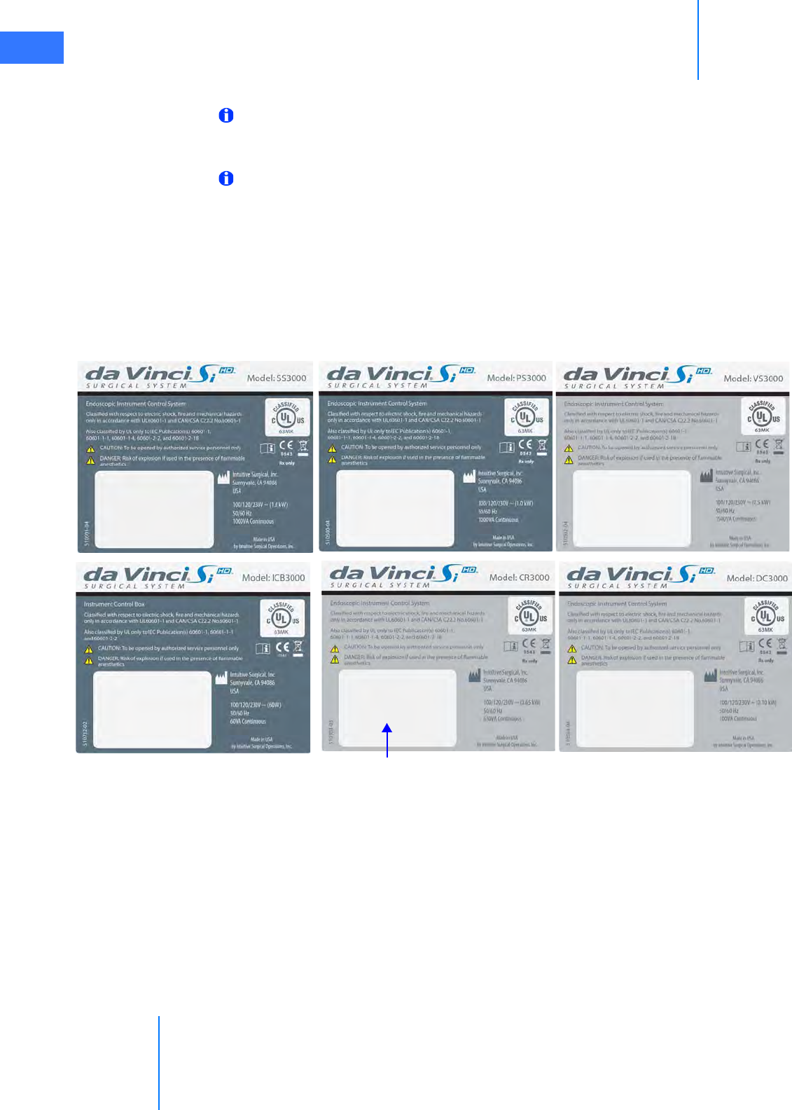
Model IS3000 system components have individual system labels as shown below, all of which
repeat the same information except to specify the model (at upper right) and power
requirements (at lower right). Components with these labels include the Surgeon Console,
Model SS3000; Patient Cart, Model PS3000 Vision Cart, Model VS3000; Instrument Control Box,
Model ICB3000; Core, Model CR3000; and Camera Control Unit (CCU), Model DC3000. The
information supplied by these labels is repeated in this chapter
Figure 1.1 System labels: IEC 2nd Edition
Space reserved for unit identifiers
(on all system labels)
da Vinci® Si™
Introduction 1-5
DRAFT/PRE-RELEASE/CONFIDENTIAL
10/9/14
Figure 1.2 System Labels: IEC 3rd Edition
Power Requirements
The da Vinci Si System has three main components requiring electrical power: the Surgeon
Console, the Patient Cart, and the Vision Cart. To ensure optimum performance, make sure
each component of the da Vinci Si System is connected to a dedicated, noise-free and
well-grounded AC power outlet.
CAUTION: To avoid overloading circuits, all three components—Surgeon Console,
Patient Cart and Vision Cart—must operate on separate, dedicated power circuits. Do
not connect ancillary devices such as insufflators or energy devices through any system
component, particularly not through the Vision Cart because it has large power
requirements. Ancillary devices must be connected to wall outlets on separate circuits
from all system components.
A label on the rear of the Vision Cart reinforces this caution. Its text appears below the label
image.
Figure 1.3 Vision Cart power caution label
“Vision Cart requires dedicated circuit. Do not connect auxiliary
equipment to the circuit powering the Vision Cart.”
Introduction
da Vinci® Si™
1-6
DRAFT/PRE-RELEASE/CONFIDENTIAL
10/9/14
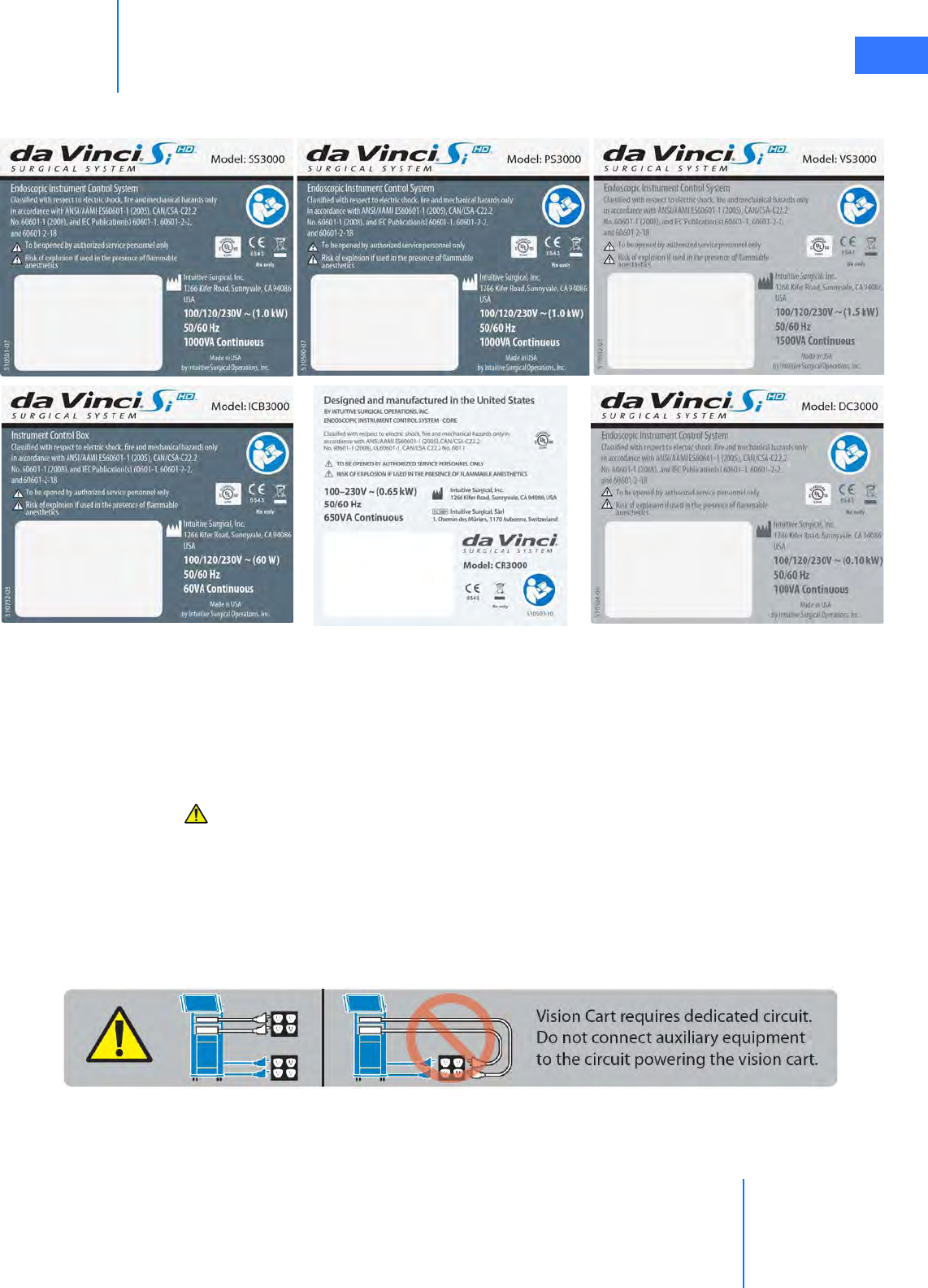
The integrated power strip in the Vision Cart also has the label below:
Figure 1.4 Vision Cart integrated power strip caution label
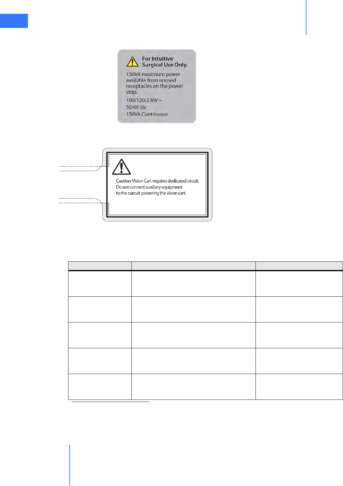
A label wrapped around the Vision Cart power cord also reinforces this point:
Figure 1.5 Vision Cart power cord caution label
The Surgeon Console, Patient Cart, and Vision Cart automatically adapt to 100VAC, 120VAC, or
230VAC. (This is called “Auto Sense” in the table below.) Please refer to the electrical rating
label located on the bottom rear panel of the da Vinci Si System components.
“For Intuitive Surgical Use Only.
150 VA maximum power available from unused
receptacles on the power strip.
100/120/230V~
50/60 Hz
150 VA Continuous”
Caution: Vision Cart requires dedicated
circuit. Do not connect auxiliary equipment to
the circuit powering the Vision Cart.
System Component Voltage Rating
Surgeon Console
100/120/230V~
50/60Hz
Auto Sense
1000VA Continuous
Patient Cart
100/120/230V~
50/60Hz
Auto Sense
1000VA Continuous
Vision Cart–
includes Core and
Camera Control Unit
100/120/230V~
50/60Hz
Auto Sense
1500VA Continuous
Corea,b
100/120/230V~ or 100-230V~
50/60Hz
Auto Sense
650VA Continuous
Camera Control Unit
(CCU)a
100/120/230V~
50/60Hz
Auto Sense
100VA Continuous
a. Core and Camera Control Unit (CCU) power requirements are included in the Vision Cart.
These are provided separately for reference only.
b. If the Core is powered separately from the Vision Cart, it must be powered from a cen-
ter-tapped, 240V, single phase circuit. This applies to the US only.

da Vinci® Si™
Introduction 1-7
DRAFT/PRE-RELEASE/CONFIDENTIAL
10/9/14
Environmental Specifications
Note: Storage and transport of the system are not affected by atmospheric pressure.
1.3 Professional Instructions for Use
Essential Prescribing Information
•Device Name: Intuitive Surgical® da Vinci® Si™ Endoscopic Instrument Control System and
Endoscopic Instruments.
•Rx only: Federal Law (USA) restricts this device to sale by or on the order of a physician
(or properly licensed practitioner).
Indications for Use
The Intuitive Surgical Endoscopic Instrument Control System is intended to assist in the
accurate control of Intuitive Surgical Endoscopic Instruments including rigid endoscopes,
blunt and sharp endoscopic dissectors, scissors, scalpels, ultrasonic shears, forceps/pick-ups,
needle holders, endoscopic retractors, stabilizers, electrocautery and accessories for
endoscopic manipulation of tissue, including grasping, cutting, blunt and sharp dissection,
approximation, ligation, electrocautery, suturing, and delivery and placement of microwave
and cryogenic ablation probes and accessories, during urologic surgical procedures, general
laparoscopic surgical procedures, gynecologic laparoscopic surgical procedures, transoral
otolaryngology surgical procedures restricted to benign and malignant tumors classified as TI
and T2, general thoracoscopic surgical procedures, and thoracoscopically assisted cardiotomy
procedures. The system can also be employed with adjunctive mediastinotomy to perform
coronary anastomosis during cardiac revascularization. The system is indicated for adult and
Environmental Conditions: Operating
Temperature: 10 to 30 °C (50 to 86 °F)
Humidity: 10 to 85% non-condensing
Atmospheric Pressure – System:
The IS3000 shall function properly in atmospheric pressures
ranging from 523 mm HG (10,000 ft) to 774 mm HG (-500 ft). For
every 1000 feet above sea level, the 30 °C operational temperature
limit specified above will be reduced by 1 °C. (For example, the
maximum operating temperature at 5000 feet will be 25 °C, and
the maximum operating temperature at 10,000 feet will be 20 °C.)
Atmospheric Pressure – Instrument Control
Box (ICB):
The ICB shall function properly in atmospheric pressures ranging
from 526 mm HG (3000 m) to 774 mm HG (-150 m). For every 300
m above sea level, the 30 °C operational temperature limit
specified above will be reduced by 1 °C. (For example, the
maximum operating temperature at 1500 m will be 25 °C, and the
maximum operating temperature at 3000 m will be 20 °C.)
Environmental Conditions: Storage and Transport
Temperature: -10 to 55 °C (14 to 131 °F)
Humidity: 5 to 95% non-condensing for transport
10 to 85% non-condensing for storage

Introduction
da Vinci® Si™
1-8
DRAFT/PRE-RELEASE/CONFIDENTIAL
10/9/14
pediatric use (except for transoral otolaryngology surgical procedures). It is intended to be
used by trained physicians in an operating room environment in accordance with the
representative, specific procedures set forth in the Professional Instructions for Use.
Representative Uses
The Intuitive Surgical Endoscopic Instrument Control System has been successfully used in the
following procedures, among others:
• Radical prostatectomy, pyeloplasty, cystectomy, nephrectomy, ureteral reimplantation
• Hysterectomy, myomectomy, sacrocolpopexy
• Cholecystectomy, Nissen fundoplication, Heller myotomy, gastric bypass, donor
nephrectomy, adrenalectomy, splenectomy, bowel resection and other colorectal
procedures
• Internal mammary artery mobilization, cardiac tissue ablation
• Mitral valve repair, endoscopic atrial septal defect closure
• Mammary to left anterior descending coronary artery anastomosis for cardiac
revascularization with adjunctive mediastinotomy
Note: For additional information and precautions related to cardiac tissue ablation,
refer to the section on ablation probes in the Instruments and Accessories User Manual.
Representative Pediatric Uses
The Intuitive Surgical Endoscopic Instrument Control System has been successfully used in the
following pediatric surgical procedures, among others;
• Pyeloplasty, ureteral reimplantation
• Cholecystectomy, Nissen fundoplication
• Aortic ring ligation, patent ductus arteriosus ligation
•Atrial septal defect closure
Training
The system should be used only by surgeons who have developed adequate robotic skills to
perform the tasks associated with each procedure and who have received specific training
provided by Intuitive Surgical, Inc. in the use of this device. Training provided by Intuitive
Surgical is limited to the use of the da Vinci Si Surgical System and does not replace the
necessary medical training and experience required to perform surgery.
WARNING: Performance characteristics for conduct of totally endoscopic coronary
artery bypass surgery (CABG) have not been fully established. The system should only
be used for CABG when there is direct surgical access to the surgical field.
WARNING: Performance characteristics of autologous venous coronary artery bypass
surgery (CABG) using the da Vinci Si Surgical System have not been established.

da Vinci® Si™
Introduction 1-9
DRAFT/PRE-RELEASE/CONFIDENTIAL
10/9/14
CAUTION: The clinical evaluation of the da Vinci Si Surgical System supporting its use
for mitral valve repair was not performed totally endoscopically. Introduction and
manipulation of the endoscopic instruments were controlled by the da Vinci Si Surgical
System through port incisions (< 1 cm) while accessory technologies, e.g., atrial
retractor and cardioplegia line, etc., were introduced through a mini-thoracotomy.
Performance characteristics for conduct of totally endoscopic mitral valve repair using
the da Vinci Si System have not been established.
CAUTION: The friable nature of pulmonary tissue enhances the risk of vascular,
bronchiolar, or other injury that will be difficult to control when using this device.
Published clinical experience as well as clinical studies performed to support this
marketing clearance have demonstrated that even surgeons considered expert in
laparoscopy/thoracoscopy have substantial learning curves of 10 to 12 cases (Falk
2000).1
Additional Considerations for Pediatric Surgical Procedures
Precautions for Use in Smaller Patients
• Performance in pediatric surgical procedures is based on similarity of tasks performed in
adult surgical procedures. As is appropriate with any surgical procedure, consideration
must be given to patient size and workspace volume when using the system and
instruments.
• As in any patient of smaller size, the possibility of misalignment of the remote center with
the body exists. In order to minimize forces on the body wall, care must be taken to
ensure the remote center is properly aligned with the body wall.
1.4 General Precautions, Warnings, and Contraindications
The da Vinci Si System is to be used in accordance with this manual and should not be moved
or used by any person who has not been trained by an Intuitive Surgical, Inc. representative.
Read all instructions carefully. Failure to properly follow instructions, notes, cautions, warnings
and danger messages associated with this equipment may lead to serious injury or surgical
complications for the patient. While these messages appear throughout the manual, this
chapter provides some general precautions.
Any and all relative and absolute contraindications to endoscopic surgical technique
applicable to the use of conventional endoscopic surgical instruments apply to the use of the
da Vinci Si System. General, non-procedure specific, contraindications to endoscopic surgery
include bleeding diathesis, morbid obesity and pregnancy.
1. Falk, et al., Total endoscopic computer enhanced coronary artery bypass graft-
ing, Eur J Cardiothorac Surg 2000; 17: 38-45.

Introduction
da Vinci® Si™
1-10
DRAFT/PRE-RELEASE/CONFIDENTIAL
10/9/14
Conversion to Non-Minimally Invasive Technique
CAUTION: Although the da Vinci Si System is safe and reliable, anatomical
characteristics of a patient may preclude using minimally invasive techniques.
Environmental or equipment failures may cause the da Vinci Si System to be unavailable.
The surgical team should always have backup equipment and instrumentation
available, and be prepared to convert to alternative surgical techniques. The potential
risk of such conversion should be communicated to the patient.
Endoscopic Procedure Precautions
Only physicians having adequate training and experience with endoscopic techniques should
perform endoscopic procedures with the da Vinci Si System. Medical literature should be
consulted regarding techniques, complications, and hazards before performing any
endoscopic procedure.
WARNING: Hazards may exist with over-insufflation, such as gas embolism.
CAUTION: When using the da Vinci Si System with insufflation, only CO2 should be used
as the insufflating gas. Insufflation should only be performed by personnel having
adequate training and experience with this technique.
CAUTION: Thermal hazards may exist from high temperatures. Eye hazards may exist
from the high energy light radiated by the endoscopic camera and illumination system.
Only personnel having adequate training and experience with the endoscopic camera
and illumination system should operate such equipment. All WARNING and CAUTION
messages provided with the endoscopic camera and illumination system must be
followed.
CAUTION: The da Vinci Si is not suitable for use in the presence of a flammable
anesthetic mixture of air, oxygen and/or nitrous oxide.
CAUTION: The force feedback associated with the da Vinci Si System is different from
feedback experienced when using conventional instruments. As with any endoscopic
procedure, the surgeon should rely on visual cues to enhance force feedback.
CAUTION: Do not clean instrument tips with another instrument intraoperatively. If an
instrument tip requires cleaning, remove the instrument from the cannula and gently
clean the tip.
High Frequency Electrosurgery Precautions
The safe and effective use of endoscopic electrosurgery largely depends on factors solely
under the control of the operating surgeon. Only surgeons having adequate training and
experience with endoscopic electrosurgery should perform endoscopic procedures involving
electrosurgery. The instructions, warnings and cautions provided with the Electrosurgical
Generator Unit (ESU) must be followed or else serious injury or surgical complications may
occur to the patient.
CAUTION: Do not use electrosurgical equipment unless properly trained in the specific
procedure being undertaken. Follow all instructions, warnings, and cautions provided
with the ESU.

da Vinci® Si™
Introduction 1-11
DRAFT/PRE-RELEASE/CONFIDENTIAL
10/9/14
CAUTION: Inadvertent electrosurgical energy may cause serious injury or surgical
complications to the patient. It is important to ensure a full understanding of the
da Vinci Surgical System energy user interface and use caution when working near
critical anatomy.
CAUTION: The Intuitive Surgical monopolar electrosurgical instruments are designed
for use with a maximum peak voltage of 3kV (6kV peak-to-peak). Do not use settings on
the ESU that exceed a 3kV peak. Do not attempt to use the footswitch on the Surgeon
Console with ESUs that are not compatible with the da Vinci Si System. Consult with your
Intuitive Surgical representative regarding compatible models. A table in the
Instruments and Accessories User Manual lists compatible generators, modes and
maximum power settings to stay below the 3kV peak limit.
CAUTION: Electrosurgery may produce interference with internal or external
pacemakers. Electrosurgery may cause these devices to enter an asynchronous mode or
may inhibit pacemaker operation entirely. Consult the pacemaker manufacturer for
further information when using electrosurgery in patients with cardiac pacemakers.
CAUTION: Always check the cables, ESU, and instruments for insulation damage and
proper function before use.
CAUTION: To avoid inadvertent thermal damage to surrounding tissue and other
hazards, observe the following.
• Ensure that the dispersive electrode is securely affixed to the patient, placed as close as
possible to the operating field, and properly connected to the ESU.
• For monopolar instruments, always use the lowest output setting that achieves the
desired surgical effect while staying within 3kV maximum peak voltage. Maximum power
levels to stay below this limit are listed in a table in the Instruments and Accessories User
Manual.
• Do not deliberately or unintentionally use one instrument to energize other endoscopic
instruments. Energizing other endoscopic instruments may cause tissue damage inside
or outside the field of view. This damage could occur at points near the tip or at the port
site (cannula) of the energized instrument.
• Secure and route the ESU cable to the Intuitive Surgical Instrument to prevent cable
damage and unintended disconnection.
• Keep patient from coming in contact with grounded metal parts.
• Place any monitoring electrodes as far as possible from the surgical electrodes or the
dispersive electrode when high frequency (HF) surgical equipment and physiological
monitoring equipment are used simultaneously on the same patient.
• Do not use flammable anesthetics or oxidizing gases such as nitrous oxide and oxygen.
• Use only non-flammable agents for cleaning and disinfecting. If flammable agents are
used for cleaning or disinfecting or as solvents, they must be allowed to evaporate before
application of HF energy.
CAUTION: Make certain that the ESU audible output can be heard by the operating
surgeon during ESU use with the da Vinci Si System.

Introduction
da Vinci® Si™
1-12
DRAFT/PRE-RELEASE/CONFIDENTIAL
10/9/14
Installation and Service Precautions
CAUTION: The da Vinci Si System may only be installed and serviced by Intuitive Surgical
personnel. DO NOT attempt to install or service equipment without Intuitive Surgical
personnel. To reduce risk of electric shock, DO NOT open or remove covers except as
instructed in this user manual.
WARNING: No modification of this equipment is allowed.
WARNING: To avoid risk of electric shock, this equipment must only be connected to a
supply mains with protective earth.
Building Vibrations
It is possible for ambient vibrations in the building to be transmitted through the operating
room floor to the instrument tips. When present, such vibrations may be more noticeable
when using the da Vinci System in procedures where cannulae are not inserted through the
patient body wall. Be aware of this possibility when deciding where to install and when to use
the da Vinci System. The system has no specification for permissible levels of ambient
vibration.
Floor Angle
The da Vinci Si System must be installed on a level floor.
Laser Safety
Class 1 Laser Product: The IS3000 circuit boards may be equipped with optical
communication transmitters, which have been evaluated and found to be in compliance with
requirements found within 21 CFR (FDA-CDRH) and EN 60825-1 for Class 1 laser devices.
CAUTION: While Class 1 laser products are considered to be “eye safe” without the need
for additional protection, when working around the circuit boards, the following
general safety guidelines should be observed to reduce the risk of eye injury:
• Do not look or stare at optical fiber ports or optical fibers that are connected to a light
source.
• Do not examine with optical instruments optical fiber ports or optical fibers that are
connected to a source. The use of optical instruments (for example, a magnifying glass)
may increase eye hazard.
• Adjustments and settings, maintenance, operational parameters and procedures other
than those specified and allowed herein and on the rating plate of the IS3000 may result
in increased eye hazard.
• Do not attempt to perform any repair or maintenance on optical communications
components. Repairs and maintenance outside that which is allowed herein must be
performed only by an authorized repair facility.
Transportation and Storage Precautions
When transporting or storing the da Vinci Si System, the Patient Cart should have the
instruments and camera removed and the setup joints folded-in toward the center column
(see 11.4 Storing the System on page 11-4 for an example of what the Patient Cart looks like
with the arms folded). To move the Surgeon Console, release both brakes. Always use the
da Vinci® Si™
Introduction 1-13
DRAFT/PRE-RELEASE/CONFIDENTIAL
10/9/14
handles on the sides of the Surgeon Console to move the console. Always use the handle on
the Patient Cart to move the cart. See Chapter2 System Overview and Appendix J: Glossary of
Terms for definitions. For instructions on moving the Patient Cart, see Motor Drive Operation
on page 3-3.
Note: Use extreme care when moving or positioning the Patient Cart to ensure the arms
do not hit any objects. If an arm hits an object while the Patient Cart is being moved or
positioned, contact Intuitive Surgical Technical Support to have the Patient Cart
inspected for damage.
CAUTION: The Surgeon Console and Patient Cart are heavy and may present a hazard if
control is lost when moving. Only trained personnel should attempt to move the da Vinci
Si System.
Instrument and Endoscope Isolation Precautions
The cannula mounts, sterile adapters and instrument insulation are isolation barriers to
electrical current. These parts need to be maintained unmodified for patient safety.
CAUTION: Do not modify the cannula mounts, sterile adapters or instruments.
Modifications can result in electrical hazards or performance degradation.
Arm Positioning Precautions
CAUTION: When activating the port clutch or instrument clutch buttons, keep fingers
clear of the joints located on the camera and instrument arms to avoid injury.
•The label at left, which indicates a pinch or crush hazard, appears below the upper port
clutch button and at the junction of setup joint and top of column on instrument and
camera arms. It also appears on the Surgeon Console on the top of the column and rear
and sides of the stereo viewer, and on the sides and top of the linkages connecting the
stereo viewer to its supports.
CAUTION: Do not touch any wire harnesses or mechanical cables located on the camera
or instrument arms while simultaneously touching the patient or when positioning the
arms.
Accessory Equipment Interconnection
Accessory equipment connected to the analog and digital interfaces must be certified to the
respective IEC standards (i.e. IEC 60950 for data processing equipment and IEC 60601-1 for
medical equipment.) All configurations shall comply with the system standard IEC 60601-1-1.
Anyone connecting additional equipment to the signal input part or signal output part
configures a medical system, and is therefore responsible for ensuring that the system
complies with requirements of the system standard IEC 60601-1-1. If you have any questions,
please contact your Intuitive Surgical representative.
CAUTION: Leakage current from interconnected electrical equipment may exceed safe
levels. In order to maintain patient and user safety, it is important to interconnect only
with devices in compliance with IEC 60601-1-1 requirements. It is the responsibility of
the user to ensure that any interconnected equipment not supplied by Intuitive Surgical
maintains compliance with IEC 60601-1-1 requirements.

Introduction
da Vinci® Si™
1-14
DRAFT/PRE-RELEASE/CONFIDENTIAL
10/9/14
CAUTION: Leakage currents from other endoscopic instruments may be
additive. To ensure maximum safety for the patient, only Type CF endoscopic
accessories should be used with the da Vinci Si System.
Potential Equalization
Where required by national laws or local regulations, equipotential bonding of equipment
may be accomplished by connecting an potential equalization conductor to the equipotential
terminals located near the mains inlet on each sub assembly of the system. See the
requirements for medical electrical systems in standard IEC 60601-1.
Viewing 3D Images Precaution
The following general caution derives from the general impact on some people of viewing 3D
images, which is related to viewing certain flashing images or lights in video or television
images. If you or your family has history of epilepsy or stroke, please consult with a medical
specialist before viewing 3D images in the stereo viewer of the Surgeon Console, or on
external third-party 3D monitors.
CAUTION: Some users who view 3D images in the stereo viewer or external
third-party 3D monitors may experience seizures; altered vision; lightheadedness;
dizziness; involuntary movements such as eye or muscle twitching; confusion;
nausea; loss of awareness; convulsions; cramps; and/or disorientation. Viewing 3D
images in the stereo viewer or external third-party 3D monitors may also cause
motion sickness, perceptual after effects, eye strain and decreased postural stability.
If you have any of the above symptoms, immediately discontinue use of this device
and do not resume until symptoms have subsided.
1.5 Electromagnetic Compatibility
The IS3000 has been tested and found to be in compliance with IEC 60601-1-2, International
standard for Medical electrical equipment - Part 1-2: General requirements for basic
safety and essential performance - Collateral standard: Electromagnetic compatibility -
Requirements and tests. It is intended to be used in an operating room environment and
operation of the IS3000 is unaffected when used in the electromagnetic environment as
specified in Tables 2 – 4 below in this section 1.5 Electromagnetic Compatibility. Special
precautions and installation information for the IS3000 for electromagnetic compatibility
(EMC) are provided in this section.
The performance of the IS3000 system is unaffected when exposed to full range of
electromagnetic environment as described in the IEC 60601-1-2 standard. There is no
degradation of performance and therefore no risks to the patient or other devices due to
Electromagnetic Interference (EMI) when used in the electromagnetic environment as
specified in Tables 2 – 4 below in this section 1.5 Electromagnetic Compatibility.
Use only Intuitive Surgical-branded interconnection cables and accessories. Performance of
cables or accessories other than those specified by Intuitive Surgical as replacement parts for
internal components cannot be guaranteed. Any resulting damage to the system will not be
covered under warranty.
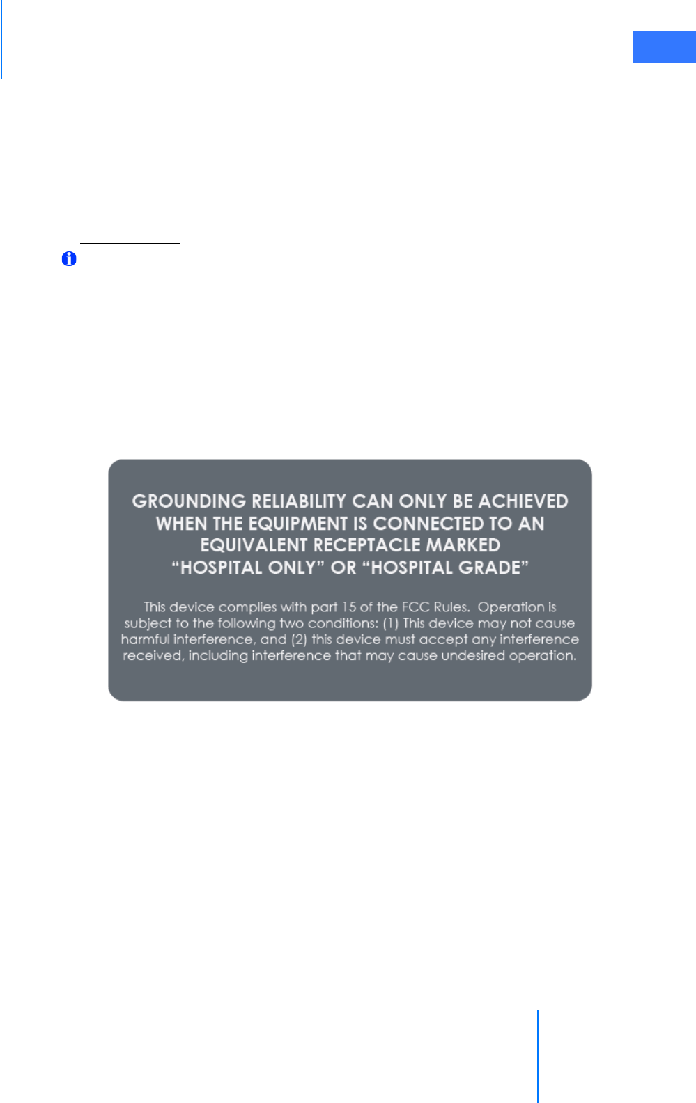
da Vinci® Si™
Introduction 1-15
DRAFT/PRE-RELEASE/CONFIDENTIAL
10/9/14
Equipment in the operating room, including the IS3000 and other portable or mobile
communications equipment, can produce Electromagnetic Interference (EMI), which may
affect the function of these devices. Such effects are prevented by use of equipment with EMI
characteristics proven below recognized limits, as identified in the below tables.
In the event of suspected interference from other equipment, which prevents the proper
functioning of the da Vinci Surgical System, contact Intuitive Surgical and/or discontinue use of
the system until the problem can be remedied.
FCC Compliance
Note: This equipment has been tested and found to comply with the limits for a Class A
digital device, pursuant to Part 15 of the FCC Rules. These limits are designed to provide
reasonable protection against harmful interference when the equipment is operated in
a commercial environment. This equipment generates, uses, and can radiate radio
frequency energy, and if not installed and used in accordance with the instruction
manual, may cause harmful interference to radio communications. Operation of this
equipment in a residential area is likely to cause harmful interference in which case the
user will be required to correct the interference at his own expense.
In regard to grounding reliability and electromagnetic interference, see the label below, which
appears on the Surgeon Console and Patient Cart. Its text is repeated below the label image:
GROUNDING RELIABILITY CAN ONLY BE ACHIEVED
WHEN THE EQUIPMENT IS CONNECTED TO AN
EQUIVALENT RECEPTACLE MARKED
“HOSPITAL ONLY” OR “HOSPITAL GRADE”
This device complies with part 15 of the FCC Rules. Operation is
subject to the following two conditions: (1) This device may not cause
harmful interference, and (2) this device must accept any interference
received, including interference that may cause undesired operation.

Introduction
da Vinci® Si™
1-16
DRAFT/PRE-RELEASE/CONFIDENTIAL
10/9/14
EMC Tables
The following tables contain the Manufacturer’s declaration and additional information
required by IEC60601-1-2.
Table 1: Manufacturer’s Declaration – Electromagnetic Emissions
The IS3000 is intended for use in the electromagnetic environment specified below. The customer or the user
of the IS3000 should assure that it is used in such an environment.
Emissions Test Compliance Electromagnetic Environment – Guidance
RF emissions CISPR 11
Group 1 The IS3000 uses RF energy only for its internal
function. Therefore, its RF emissions are very low
and are not likely to cause any interference in
nearby electronic environment.
RF emissions CISPR 11 Class A The IS3000 is suitable for use in all establishments,
other than domestic establishments and those
directly connected to the public low-voltage
power supply network that supplies buildings
used for domestic purposes.
Harmonic emissions IEC 61000-3-2 Class A
Voltage fluctuations/ flicker
emissions IEC 61000-3-3
Complies

da Vinci® Si™
Introduction 1-17
DRAFT/PRE-RELEASE/CONFIDENTIAL
10/9/14
Table 2: Manufacturer’s Declaration – Electromagnetic Immunity
The IS3000 is intended for use in the electromagnetic environment specified below. The customer or the user
of the IS3000 should assure that it is used in such an environment.
Immunity Test IEC 60601 Test Level Compliance Level Electromagnetic
Environment Guidance
Electrostatic discharge
(ESD) IEC 61000-4-2
±6 kV contact ±8 kV air ±6 kV contact ±8 kV air Floors should be wood,
concrete or ceramic tile. If
floors are covered with
synthetic material, the
relative humidity should
be at least 30%.
Electrical fast
transient/burst IEC
61000-4-4
±2 kV for power supply
lines ±1 kV for input/
output lines
±2 kV for power supply
lines ±1 kV for input/
output lines
Mains power quality
should be that of a US
commercial or hospital
environment with highly
reliable service.
Surge IEC 61000-4-5
±1 kV differential mode ±2
kV common mode
±1 kV differential mode ±2
kV common mode
Mains power quality
should be that of a US
commercial or hospital
environment with highly
reliable service.
Voltage dips, short
interruptions and voltage
variations on power supply
input lines IEC 61000-4-11
<5% UT (>95% dip in UT)
for 0.5 cycle 40% UT (60%
dip in UT) for 5 cycles 70%
UT (30% dip in UT) for 25
cycles <5% UT (>95% dip
in UT) for 5 sec.
<5% UT (>95% dip in UT)
for 0.5 cycle 40% UT (60%
dip in UT) for 5 cycles 70%
UT (30% dip in UT) for 25
cycles <5% UT (>95% dip
in UT) for 5 sec.
Mains power quality
should be that of a US
commercial or hospital
environment with highly
reliable service. If the user
of the IS3000 requires
continued operation
during power mains
interruptions, it is
recommended that the
IS3000 be powered from
an uninterruptible power
supply.
Power frequency (50/60
Hz) magnetic field IEC
61000-4-8
3 A/m 3 A/m Power frequency
magnetic fields should be
at levels characteristic of a
typical location in a typical
commercial or hospital
environment.
Note: UT is the AC mains voltage before application of the test level.
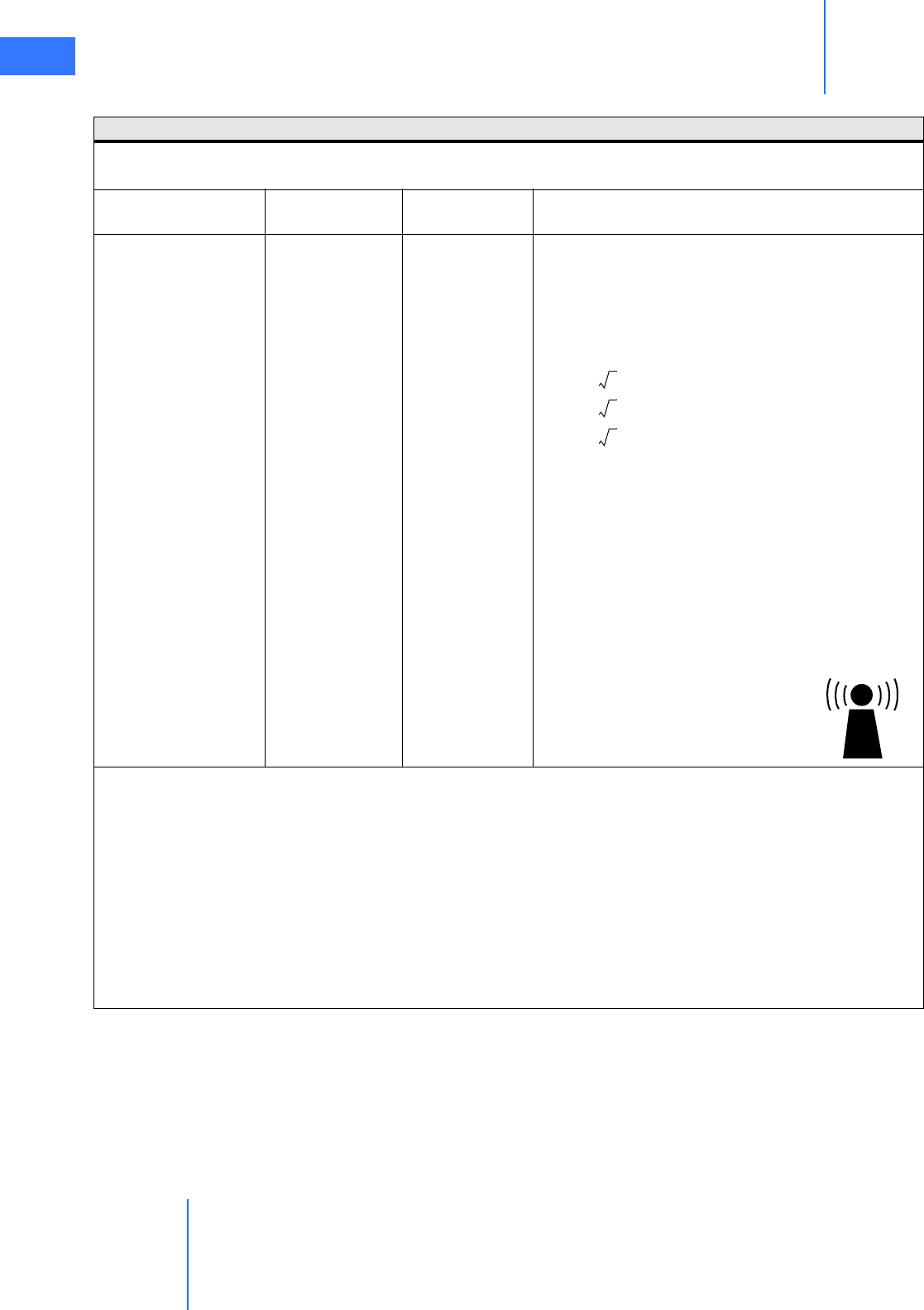
Introduction
da Vinci® Si™
1-18
DRAFT/PRE-RELEASE/CONFIDENTIAL
10/9/14
Table 3: Manufacturer’s Declaration – Electromagnetic Immunity
The IS3000 is intended for use in the electromagnetic environment specified below. The customer or the user
of the IS3000 should assure that it is used in such an environment.
Immunity test IEC 60601 test
level Compliance level Electromagnetic environment – guidance
Conducted RF IEC
61000-4-6
Radiated RF IEC
61000-4-3
3 Vrms 150 kHz
to 80 MHz
3 V/m 80 MHz to
2.5 GHz
3 Vrms
3V/m
Portable and mobile RF communications
equipment should be used no closer to any part of
the IS3000, including cables, than the
recommended separation distance calculated from
the equation applicable to the frequency of the
transmitter. Recommended separation distance
80 MHz to 800 MHz
800 MHz to 2.5 GHz
where P is the maximum output power rating of
the transmitter in watts (W) according to the
transmitter manufacturer and d is the
recommended separation distance in meters (m).
Field strengths from fixed RF transmitters, as
determined by an electromagnetic site survey,a
should be less than the compliance level in each
frequency range.b Interference may occur in the
vicinity of equipment marked with the following
symbol:
Note 1: At 80 MHz and 800 MHz, the higher frequency range applies.
Note 2: These guidelines may not apply in all situations. Electromagnetic propagation is affected by
absorption and reflection from structures, objects and people.
a. Field strengths from fixed transmitters, such as base stations for radio (cellular/cordless) telephones and
land mobile radios, amateur radio, AM and FM radio broadcast and TV broadcast cannot be predicted
theoretically with accuracy. To assess the electromagnetic environment due to fixed RF transmitters, an
electromagnetic site survey should be considered. If the measured field strength in the location in which the
IS3000 is used exceeds the applicable RF compliance level above, the IS3000 should be observed to verify
normal operation. If abnormal performance is observed, additional measures may be necessary, such as
re-orientating or relocating the IS3000.
b. Over the frequency range 150 kHz to 80 MHz, field strengths should be less than 3 V/m.
d1.2P=
d1.2P=
d2.3P=
da Vinci® Si™
Introduction 1-19
DRAFT/PRE-RELEASE/CONFIDENTIAL
10/9/14
1.6 Disposal Information
Dispose of in accordance with local regulations—particularly applies to electronic
components.
Battery Disposal
The da Vinci Si System contains one non-spillable, lead acid battery pack module and several
lithium batteries that are not user serviceable. These batteries must be disposed of in
accordance with local regulations. Contact your local Intuitive Surgical representative for
disposal information.
_________________________________End of section______________________________
Table 4: Recommended separation distances between portable and mobile RF
communications equipment and the IS3000
The IS3000 is intended for use in an electromagnetic environment in which radiated RF disturbances are
controlled. The customer or the user of the IS3000 can help prevent electromagnetic interferences by
maintaining a minimum distance between portable and mobile RF communications equipment (transmitters)
and the IS3000 as recommended below, according to the maximum output power of the communications
equipment.
Rated maximum output power
of transmitter W Separation distance according to frequency of transmitter m
150 kHz to 80 MHz
80 MHz to 800 MHz 800 MHz to 2.5 GHz
0.01 0.12 0.12 0.23
0.1 0.38 0.38 0.73
1 1.2 1.2 2.3
10 3.8 3.8 7.3
100 12 12 23
For transmitters rated at a maximum output power not listed above, the recommended separation distance d
in meters (m) can be estimated using the equation applicable to the frequency of the transmitter, where P is
the maximum output power rating of the transmitter in watts (W) according to the transmitter manufacturer.
Note 1: At 80 MHz to 800 MHz, the separation distance for the higher frequency range applies.
Note 2: These guidelines may not apply in all situations. Electromagnetic propagation is affected by
absorption and reflection from structures, objects and people.
d1.2P=
d1.2P=
d2.3P=
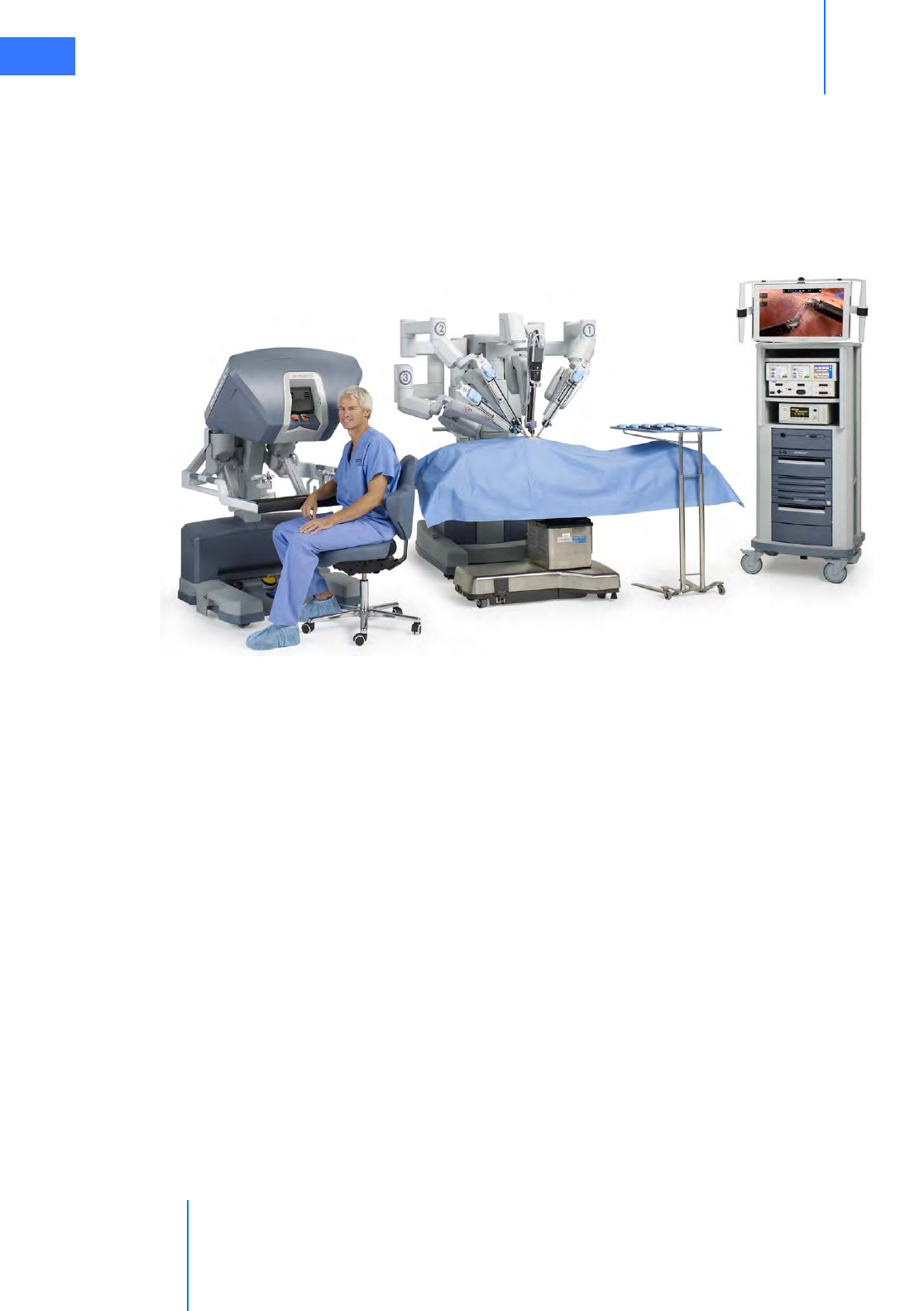
System Overview
da Vinci® Si™
2-1
DRAFT/PRE-RELEASE/CONFIDENTIAL
10/9/14
2System Overview
The da Vinci Si Surgical System is a sophisticated robotic platform designed to enable complex
surgery using a minimally invasive approach. The da Vinci Si System consists of three main
components, shown in Figure 2.1 below, from left to right: the Surgeon Console, the Patient
Cart and the Vision Cart.
Figure 2.1 Main components of the da Vinci Si Surgical System
This chapter introduces the system components in the following sections:
•2.1 The da Vinci Si System Main Components, page 2-2
•2.2 The da Vinci Si-e Surgical System, page 2-4
•2.3 Surgeon Console Overview, page 2-5
•2.4 Patient Cart Overview, page 2-8
•2.5 Vision Cart Overview, page 2-11
Surgeon Console
Patient Cart
Vision Cart
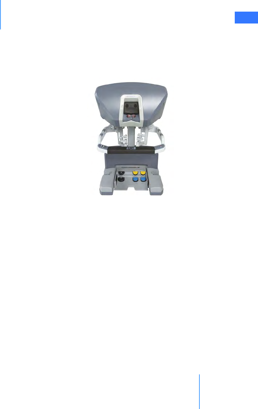
da Vinci® Si™
System Overview 2-2
DRAFT/PRE-RELEASE/CONFIDENTIAL
10/9/14
2.1 The da Vinci Si System Main Components
Surgeon Console
The Surgeon Console (Figure 2.2) is the control center for the da Vinci Si System. The surgeon
sits outside the sterile field at the Surgeon Console, using eyes, hands and feet to control a 3D
endoscope and EndoWrist® instruments, by means of two master controllers and foot pedals.
Figure 2.2 Surgeon Console
As seen in the stereo viewer, instrument tips appear to align with the surgeon's hands at the
master controllers. This design is intended to simulate the natural alignment of eye, hand and
instrument of open surgery. Natural alignment, in turn, helps to optimize hand-eye
coordination. This means that the da Vinci Si System enables dexterity comparable to open
surgery in a minimally invasive procedure. Further control is provided by motion scaling and
tremor reduction, which minimizes the impact of natural hand tremor or inadvertent
movement. The Surgeon Console operator also has the option to change the view from full
screen mode to a multi-image mode (TilePro™), which displays the 3D image of the operative
field along with up to two additional images provided by auxiliary inputs. Lastly, the Surgeon
Console has several ergonomic adjustments to accommodate a wide range of body types,
providing optimal comfort while performing surgery.
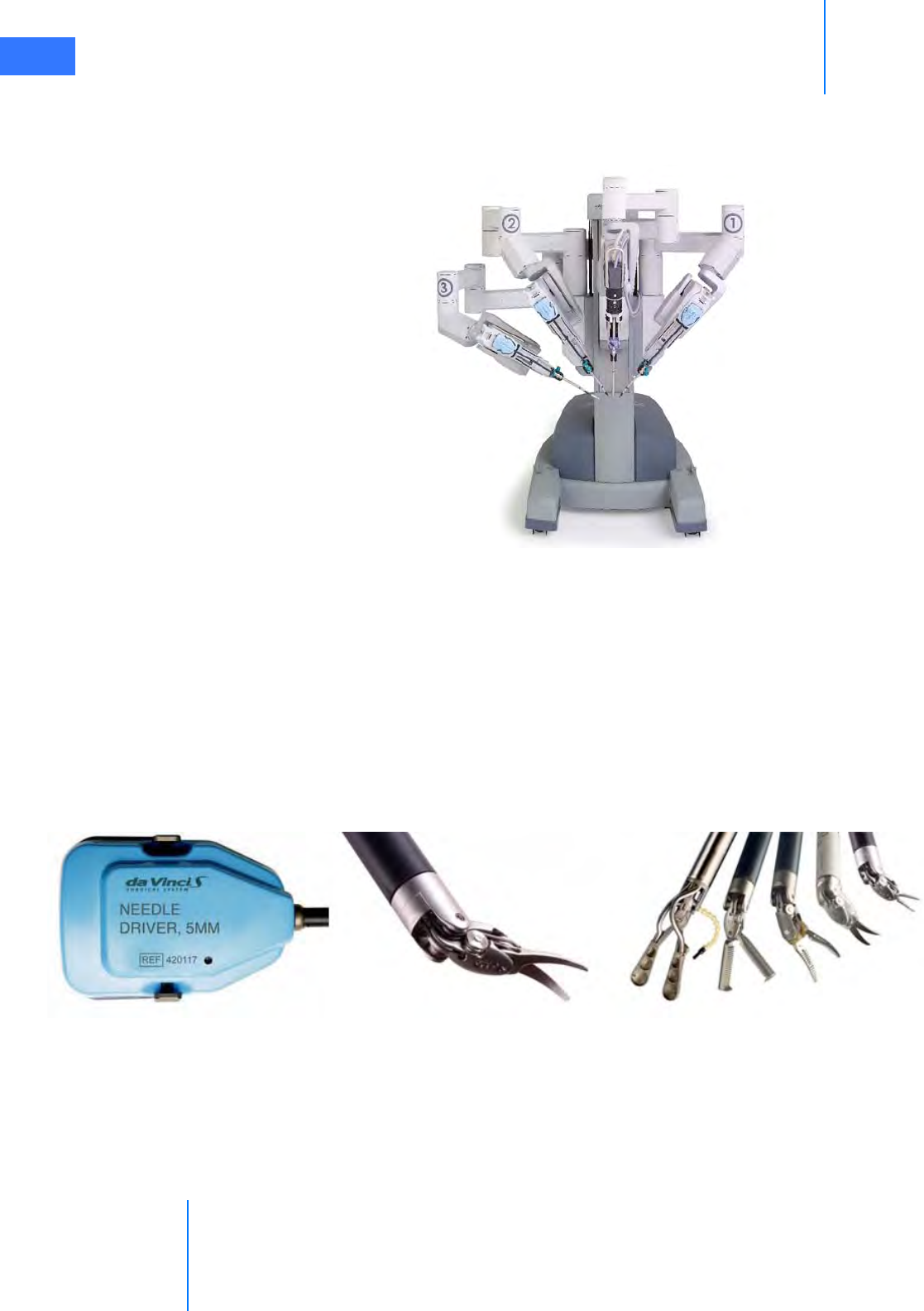
System Overview
da Vinci® Si™
2-3
DRAFT/PRE-RELEASE/CONFIDENTIAL
10/9/14
Patient Cart
The Patient Cart (Figure 2.3) is the operative component of the da Vinci Si System, and its
primary function is to support the instrument arms and camera arm.
Figure 2.3 Patient Cart
The da Vinci Si System uses remote center technology. The remote center is a fixed point in
space around which the Patient Cart arms move. Remote center technology enables the
System to maneuver instruments and endoscopes in the surgical site while exerting minimal
force on the patient's body wall.
The Patient Cart operator works in the sterile field, assisting the Surgeon Console operator by
exchanging instruments and endoscopes, and by performing other patient-side activities. To
help ensure patient-safety, the actions of the Patient Cart operator take precedence over
actions of the Surgeon Console operator.
EndoWrist Instruments
Figure 2.4 Examples of EndoWrist Instruments
Intuitive Surgical designs EndoWrist instruments to give surgeons natural dexterity and more
than natural range of motion, compared to unaided human hands. This allows for greater
precision when operating in a minimally invasive environment. EndoWrist instruments, when
used with the da Vinci Si System, are designed to support the most rapid and most precise
suturing, dissection and tissue manipulation available with any surgical platform.
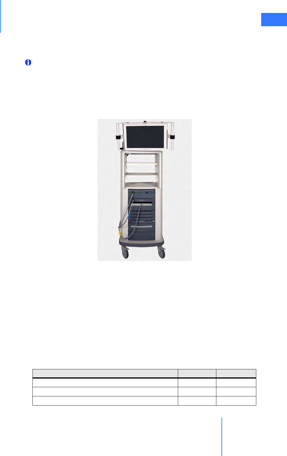
da Vinci® Si™
System Overview 2-4
DRAFT/PRE-RELEASE/CONFIDENTIAL
10/9/14
EndoWrist instruments are multi-use instruments available in 12 mm, 8 mm, and 5 mm
diameters. For a complete listing of EndoWrist instruments, please refer to the current
Instrument and Accessory Catalog (PN 871145).
Note: da Vinci Si is compatible with da Vinci S EndoWrist instruments.
Vision Cart
The Vision Cart (Figure 2.5) houses the system's central processing and vision equipment. It
includes a 24” touchscreen monitor and provides adjustable shelves for optional ancillary
surgical equipment such as ESUs and insufflators. It is operated by a non-sterile person during
surgery.
Figure 2.5 HD Vision Cart
2.2 The da Vinci Si-e Surgical System
The da Vinci Si-e Surgical System is an upgradable configuration of the da Vinci Si System,
visibly distinguished by a 3-arm Patient Cart. The da Vinci Si-e Surgical System includes an
integrated monitor on top of the Vision Cart, as in the da Vinci Si System. However, the monitor
does not have touchscreen functionality; it is a passive display system that provides OR
personnel with the patient-side display only. The da Vinci Si-e System is designed to be
upgradable at any time to a full-featured da Vinci Si System (single or dual console) – by
Intuitive Surgical technicians. The table below summarizes the Si-e feature differences. These
differences and others are further explained in Appendix B: da Vinci Si-e Surgical System.
Table 2-1 da Vinci Si vs. Si-e Comparison
Available Feature da Vinci Si da Vinci Si-e
EndoWrist® instrumentation yes yes
Single-Site™ instrumentation yes yes
Skills Simulator compatible yes yes
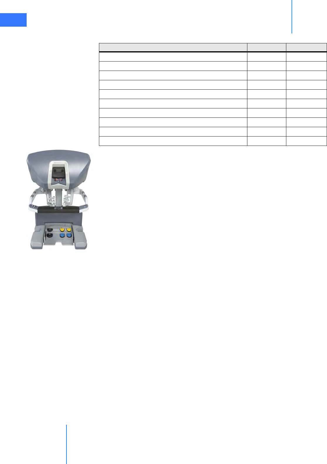
System Overview
da Vinci® Si™
2-5
DRAFT/PRE-RELEASE/CONFIDENTIAL
10/9/14
2.3 Surgeon Console Overview
In this section, the following Surgeon Console components are described:
•Master Controllers, page 2-5
•Stereo Viewer, page 2-6
•Touchpad, page 2-7
•Left-Side Pod and Right-Side Pod, page 2-7
•Footswitch Panel, page 2-8
See Chapter 10 Surgeon Console Use for detailed instructions to use the Surgeon Console.
Master Controllers
The master controllers (Figure 2.6) provide the means for the surgeon to control the
instruments and endoscope inside the patient. The master controllers are designed to allow
natural range of motion and to provide ergonomic comfort, even during extended
procedures.
To use the master controllers, the Surgeon Console operator grasps each controller with
his/her index (or middle) finger and thumb. The operator activates and controls the EndoWrist
instruments by bringing the finger and thumb together or apart; maneuvers the instruments
OnSite™ remote service yes yes
3DHD Vision System yes yes
Firefly™ Fluorescence Imaging yes yes
2-way audio system yes yes
VisionBoom™ yes yes
Dual console yes no
TilePro™ multi-image display video input yes no
Telestration yes no
Vision Cart interactive touchscreen yes no
Configurable video outputs yes no
Table 2-1 da Vinci Si vs. Si-e Comparison
Available Feature da Vinci Si da Vinci Si-e
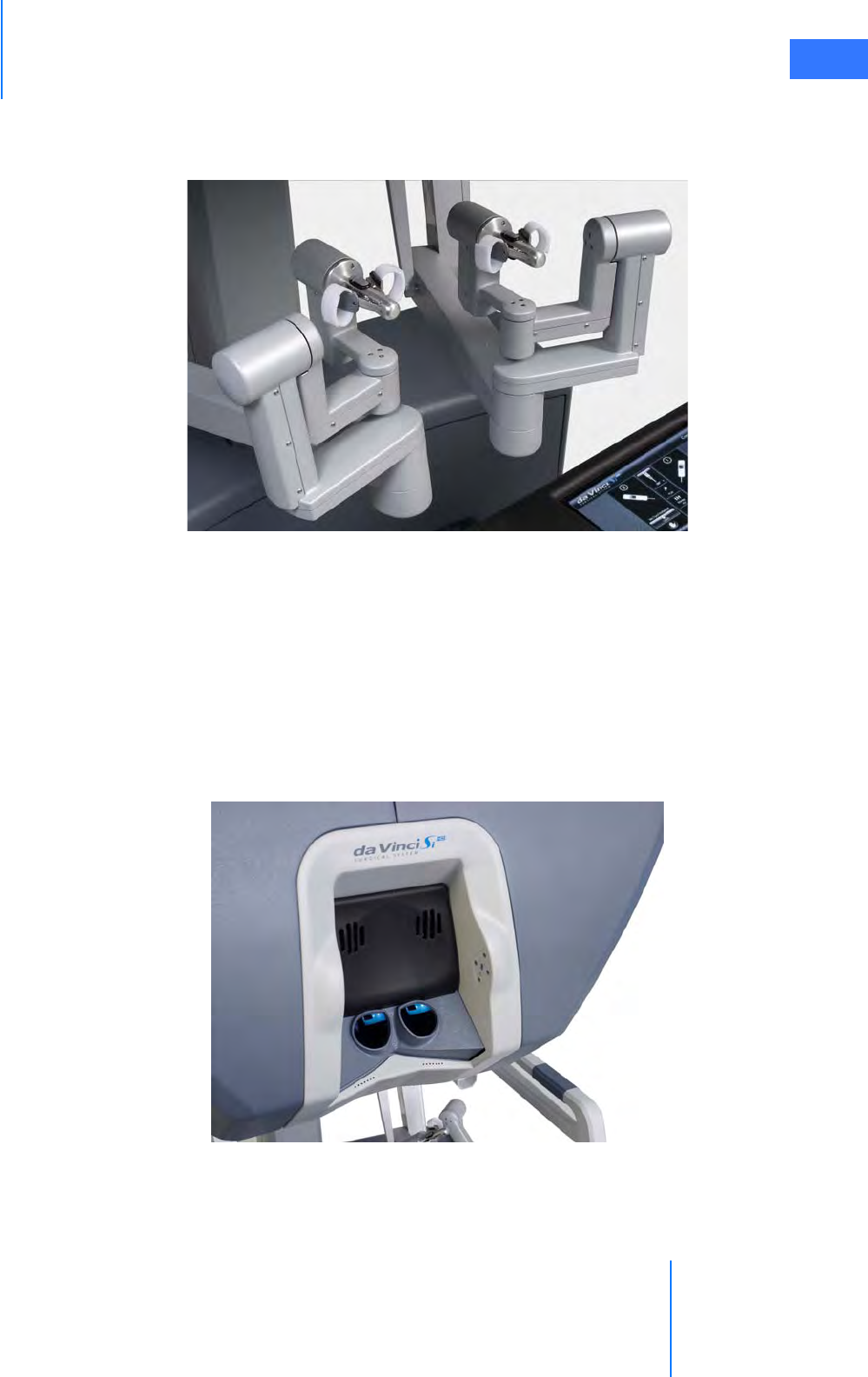
da Vinci® Si™
System Overview 2-6
DRAFT/PRE-RELEASE/CONFIDENTIAL
10/9/14
and endoscope inside the patient by moving the hands and/or arms. These movements are
precisely and seamlessly replicated at the Patient Cart, thereby virtually extending the
operator's hands into the surgical field. (See 10.4 Surgical Controls on page 10-22 for details.)
Figure 2.6 Master controllers
Stereo Viewer
The stereo viewer (Figure 2.7) provides the video image for the Surgeon Console operator. The
ergonomically designed view port provides head and neck support for added comfort during
extended procedures.
When the endoscope is activated, the stereo viewer's integrated left and right video channels
provide the surgeon with continuous 3D video, extending the vision of the surgeon into the
surgical field. The stereo viewer also displays messages and icons which convey status of the
da Vinci Si System. (See Surgical Controls on page 10-22 for details.)
Figure 2.7 Stereo viewer

System Overview
da Vinci® Si™
2-7
DRAFT/PRE-RELEASE/CONFIDENTIAL
10/9/14
Touchpad
The touchpad (Figure 2.8) is located in the middle of the Surgeon Console armrest and
provides the means for selecting various system functions. (See 10.3 Touchpad Controls on
page 10-11 for details.)
Figure 2.8 Touchpad
Left-Side Pod and Right-Side Pod
The left-side and right-side pods (Figure 2.9) are located on either side of the Surgeon Console
armrest. The left-side pod provides ergonomic controls while the right-side pod is the location
for the Power button and Emergency Stop button. (See Ergonomic Setup on page 10-10 and
5.2 Powering On the System on page 5-2 for details.)
Figure 2.9 Left-side and right-side pods
Emergency
Stop
Power
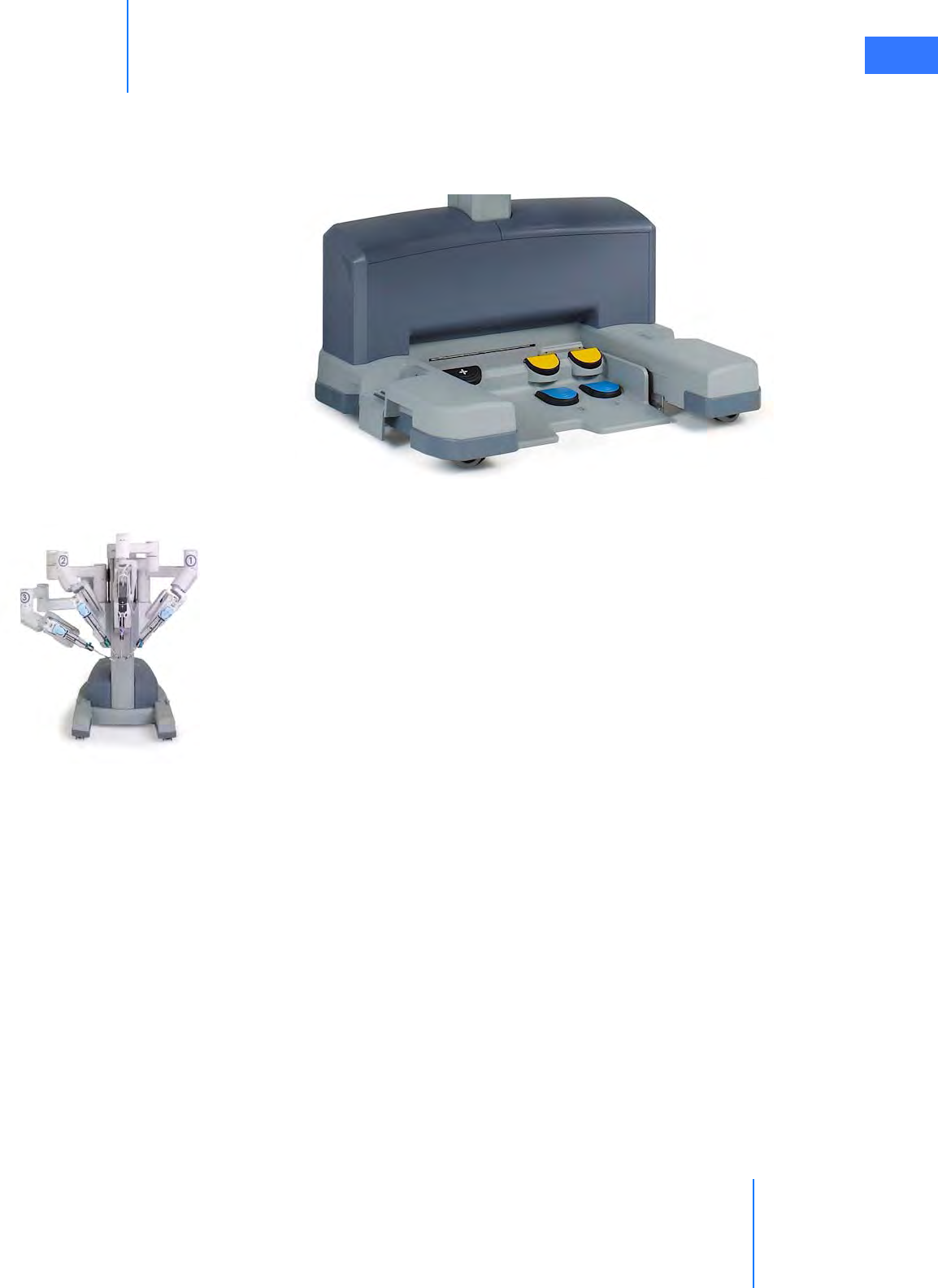
da Vinci® Si™
System Overview 2-8
DRAFT/PRE-RELEASE/CONFIDENTIAL
10/9/14
Footswitch Panel
The footswitch panel (Figure 2.10) is located on the floor directly beneath the Surgeon
Console operator and provides the interface for various surgical activities. (See Footswitch
Panel Use on page 10-24 for details.)
Figure 2.10 Footswitch panel
2.4 Patient Cart Overview
This section provides overviews for the following Patient Cart components:
•Setup Joints, page 2-9
•Instrument Arms, page 2-9
•Camera Arm, page 2-10
•Motor Drive, page 2-11
See the following chapters for detailed instructions to use the Patient Cart:
•Chapter 3 OR Configuration for instructions to use the Patient Cart motor drive
•Chapter 6 Draping for instructions to drape Patient Cart components
•Chapter 8 Patient Preparation, Port Placement, and Docking for instructions to use the
Patient Cart as you prepare for surgery
•Chapter 9 Patient Cart Use for detailed instructions to use the Patient Cart.
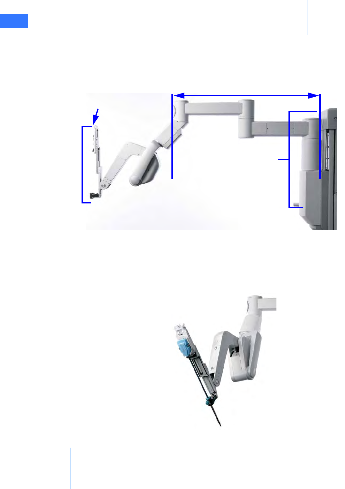
System Overview
da Vinci® Si™
2-9
DRAFT/PRE-RELEASE/CONFIDENTIAL
10/9/14
Setup Joints
Setup joints (Figure 2.11) are used to position the Patient Cart arms in order to establish the
remote center in the surgical field. Setup joints are designed with limited freedom of
movement to facilitate port placement. (See 9.2 Moving the Patient Cart Arms on page 9-3 for
details.)
Figure 2.11 setup joint
Instrument Arms
Instrument arms (Figure 2.12), once sterile drapes are applied, provide the sterile interface for
EndoWrist instruments. The Patient Cart operator initially positions the instrument arms in a
neutral position before the procedure begins. The Surgeon Console operator moves the
instrument arms using the master controllers.
Figure 2.12 Example of an instrument arm with attached instrument
Vertical range
of motion
Setup Joint
Telescoping Axis
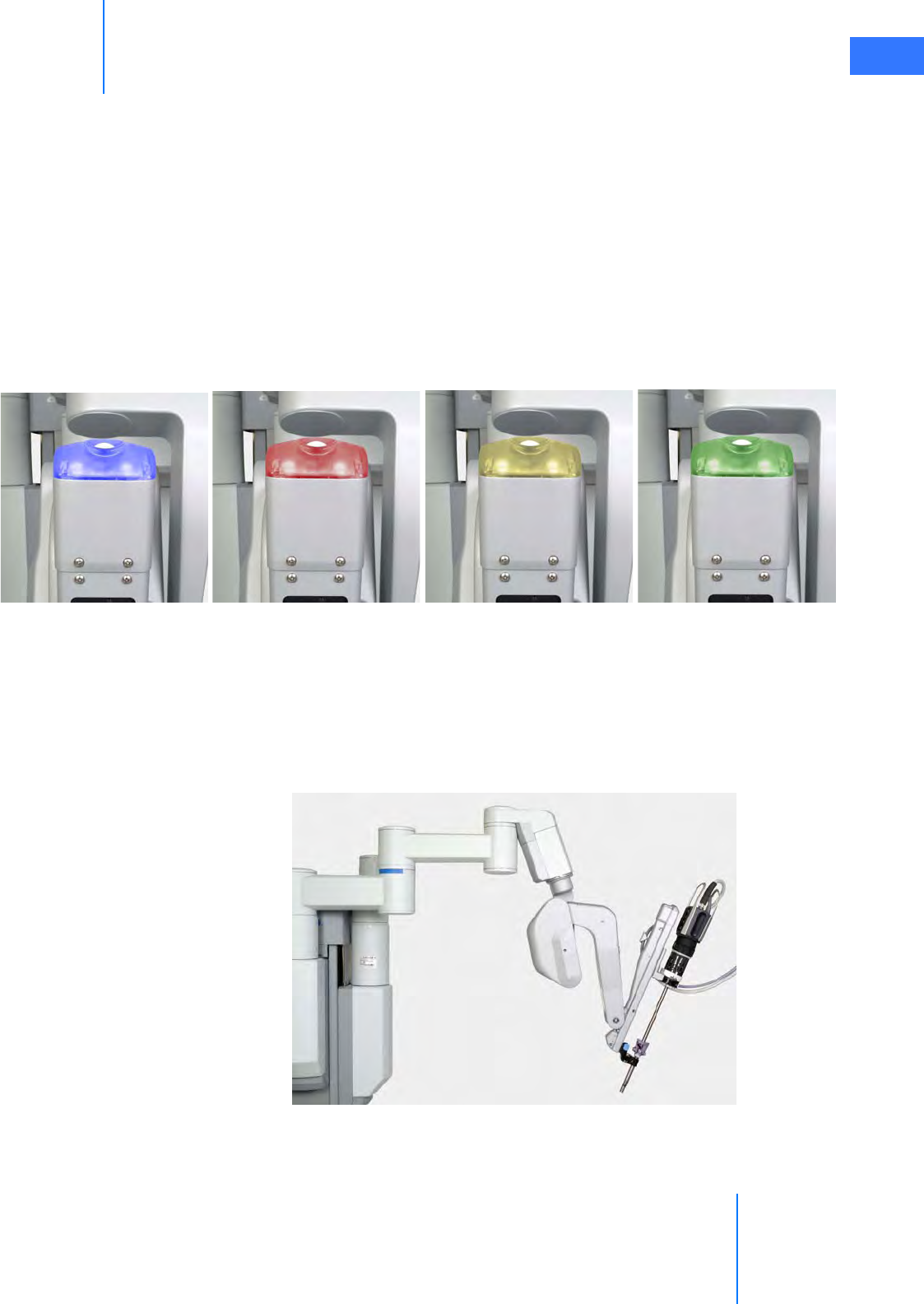
da Vinci® Si™
System Overview 2-10
DRAFT/PRE-RELEASE/CONFIDENTIAL
10/9/14
A telescoping insertion axis is designed to minimize collisions and allow the Patient Cart
operator to reposition instrument arms. da Vinci Si instrument arms also have a wide range of
motion to help simplify port setup and provide greater reach into the patient anatomy.
The instrument arm remote center is indicated by the thick, center black band on the
instrument cannula. When the Patient Cart is docked to a cannula inserted in the patient, the
instrument arm remote center should be in the patient’s body wall. This remote center
location minimizes both port-site trauma and stress exerted on the EndoWrist instruments
during surgery. The Surgeon Console operator cannot move the instrument arm remote
center. However, the Patient Cart operator can reposition the remote center by pressing the
port clutch button and repositioning the instrument arm.
At the top of the arms are LEDs which provide feedback on the status of each arm. For LED
color interpretation, see Figure 9.2 LED Quick Reference on page 9-2.
Figure 2.13 Arm LED colors
Camera Arm
The camera arm (Figure 2.14) provides the sterile interface for the 3D endoscope. The Patient
Cart operator initially positions the camera arm in a neutral position before the procedure
begins. The Surgeon Console operator moves the camera arm using the Master Controls. The
camera arm remote center is located near the tip of the camera cannula. At the top of the
camera arm is an LED to provide feedback on the status of the arm.
Figure 2.14 Camera arm with attached endoscope
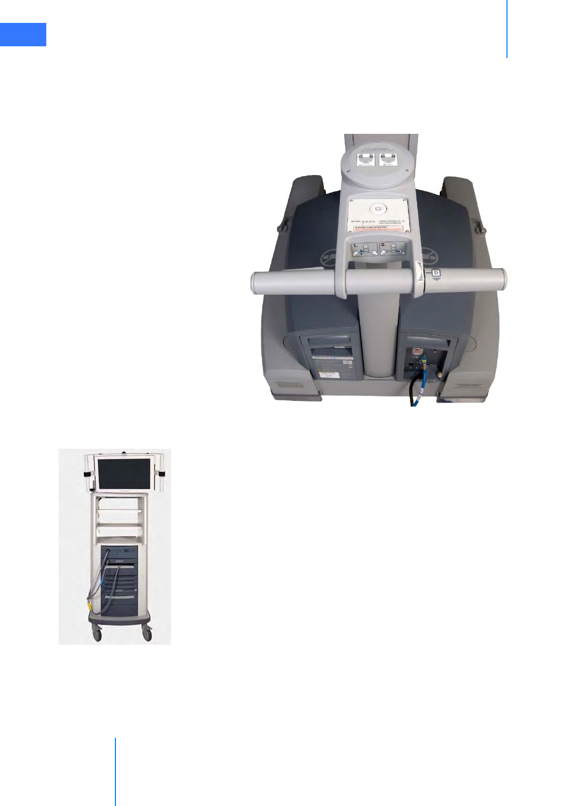
System Overview
da Vinci® Si™
2-11
DRAFT/PRE-RELEASE/CONFIDENTIAL
10/9/14
Motor Drive
The da Vinci Si Patient Cart has a motorized drive (Figure 2.15), which is designed to provide
faster and easier docking and OR re-configuration. The motor drive interface includes a
steering column, throttle, throttle-enable switch and shift switches. (See Motor Drive
Operation on page 3-3 for details.)
Figure 2.15 Motor drive steering column
2.5 Vision Cart Overview
The da Vinci Si System comes standard with a High Definition (HD) Vision System. This section
provides details regarding the following Vision Cart components:
•Core, page 2-12
•Instrument Control Box (ICB), page 2-12
•Illuminator, page 2-12
•Endoscopes, page 2-12
•HD Stereo Camera Head, page 2-14
•HD Camera Control Unit (CCU), page 2-15
•Touchscreen, page 2-16
•Tank Holders, page 2-16
The Vision Cart has three shelves to hold auxiliary equipment. Each shelf can support up to 40
lbs. (18.2 kg) provided that the total loading of all shelves not exceed 60 lbs. (27.2 kg).
See Chapter 4 System Connections for instructions to connect system components to the
Vision Cart. See Chapter 7 Vision System Use for detailed instructions to use the vision system.
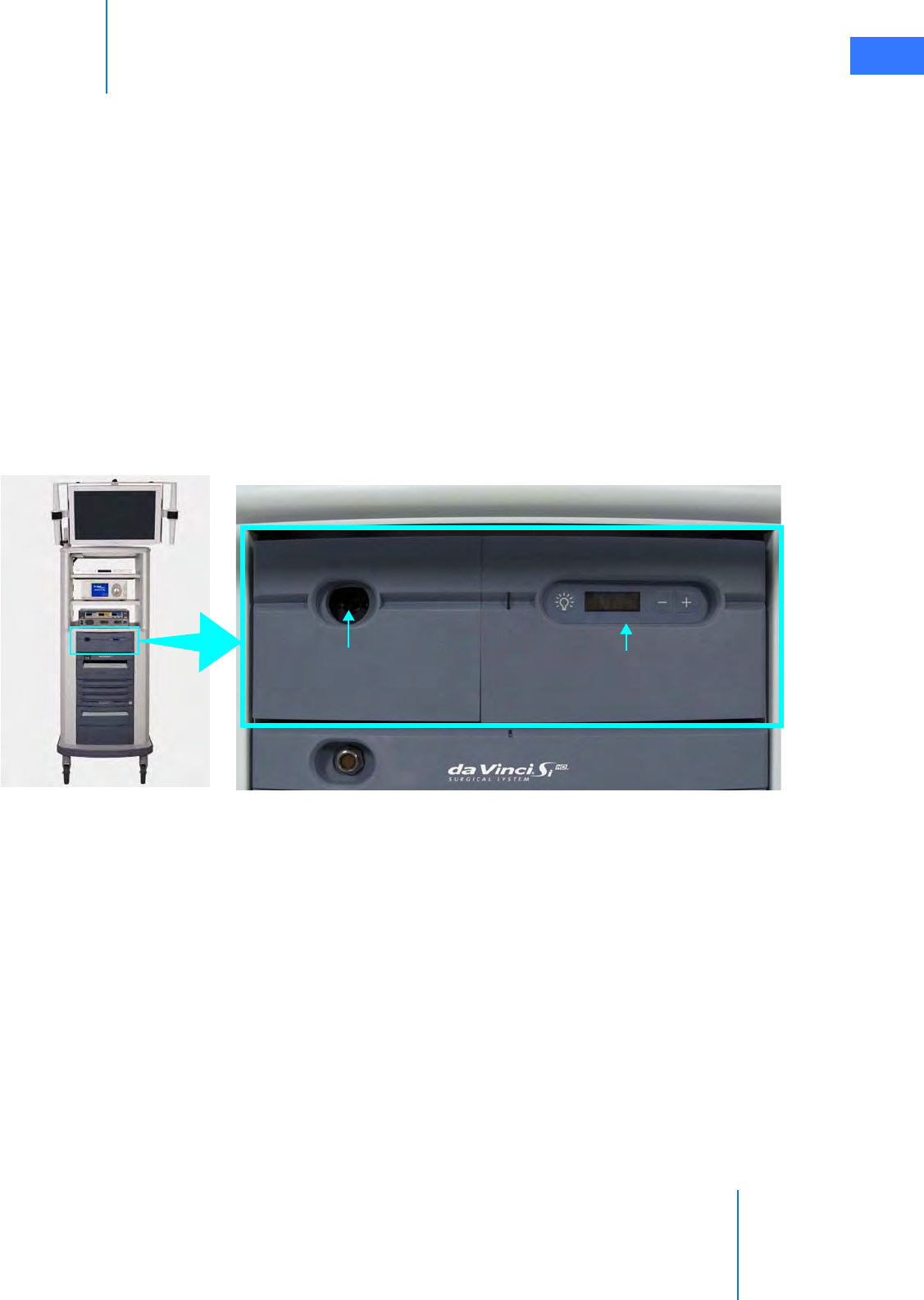
da Vinci® Si™
System Overview 2-12
DRAFT/PRE-RELEASE/CONFIDENTIAL
10/9/14
Core
The da Vinci Si Core is the system’s central connection point where all system, auxiliary
equipment, and AV connections are routed. (See Chapter 4 System Connections for details.)
Instrument Control Box (ICB)
If installed, the following information is applicable. The ICB is a hardware upgrade installed by
an Intuitive Surgical field engineer on the lower shelf of the Vision Cart. It powers certain
functions of advanced EndoWrist instruments such as the Vessel Sealer. Intuitive supplies
instructions to use the ICB as part of the instructions to use the applicable instrument.
Illuminator
Lighting for the surgical field is provided by the Illuminator (Figure 2.16). The light from the
Illuminator is delivered to the endoscope via a fiber optic light-guide cable and projected
onto the surgical site through the endoscope. The Illuminator has front panel controls for
increasing or decreasing the light output and turning the lamp on or off. (See 7.3 Working
with the Illuminator Controls on page 7-14 for details).
Figure 2.16 Illuminator and CCU
Endoscopes
The da Vinci Si HD Vision System uses a 12 mm or 8.5 mm 3D endoscope with either a straight
(0°) or angled (30°) tip. (For more detail specific to the 8.5 mm endoscope, see Appendix F:
8.5 mm Endoscope for the da Vinci Si System.) Light from the Illuminator is sent down the
shaft of the endoscope (Figure 2.17 and Figure 2.18) via fiber optics and projected onto the
surgical site. Heat from the fiber optics helps to minimize fogging at the endoscope lens. The
Light Guide Connector Intensity Display and Controls
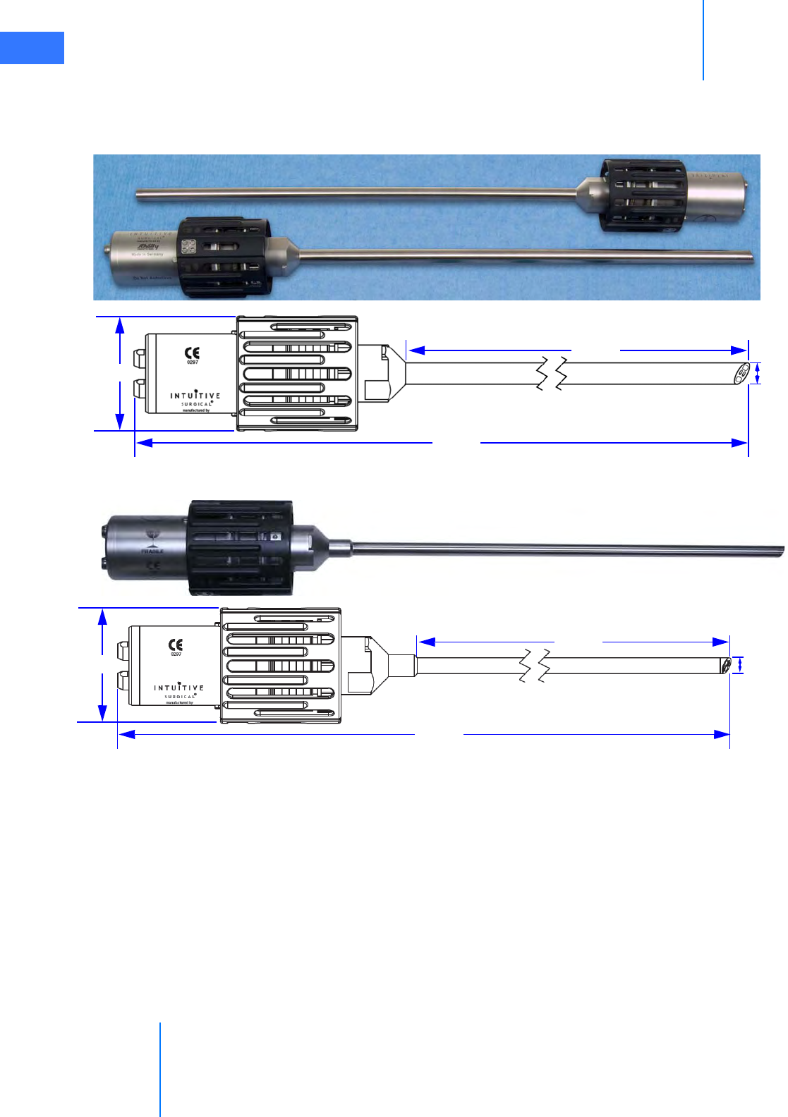
System Overview
da Vinci® Si™
2-13
DRAFT/PRE-RELEASE/CONFIDENTIAL
10/9/14
video image of the surgical site captured by the endoscope is sent back through the left and
right channels to the camera head. The camera head connects to the Camera Control Unit
(CCU), as well as the Illuminator. (See 7.2 Setting Up the Vision System on page 7-5 for details.)
Figure 2.17 da Vinci Si HD 12 mm endoscopes, with dimensions
Figure 2.18 da Vinci Si HD 8.5 mm endoscopes (30° tip), with dimensions
12 mm
554 mm
386 mm
65 mm
8.5 mm
464 mm
297 mm
65 mm
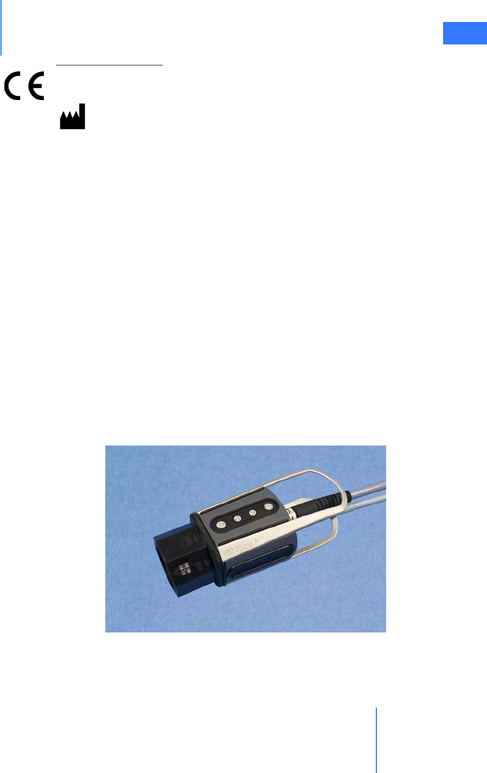
da Vinci® Si™
System Overview 2-14
DRAFT/PRE-RELEASE/CONFIDENTIAL
10/9/14
Endoscope Information
Intuitive Surgical endoscopes (see list below) are made by Schoelly Fiberoptic and distributed
by Intuitive Surgical.
Endoscopes
• 8.5 mm Endoscope (0° tip), PN 371938
• 8.5 mm Endoscope (30° tip), PN 371939
• 8.5 mm Fluorescence Endoscope (0° tip), PN 372010
• 8.5 mm Fluorescence Endoscope (30° tip), PN 372011
• 12 mm Endoscope (0° tip), PN 370890
• 12 mm Endoscope (30° tip), PN 370891
• 12 mm Fluorescence Endoscope (0° tip), PN 370892
• 12 mm Fluorescence Endoscope (30° tip), PN 370893
HD Stereo Camera Head
Figure 2.19 HD stereo camera head
Schoelly Fiberoptic GmbH
Robert-Koch-Str. 1-3
79211 Denzlingen
GERMANY
Distributed by:
Intuitive Surgical
1266 Kifer Road, Sunnyvale, California 94086 • USA
Intuitive Surgical Sàrl
1, chemin des Mûriers, 1170 Aubonne Switzerland
Customer Service from USA 1.800.876.1310
Customer Service from Europe +800.0821.2020
Manufactured in Germany.
0297

System Overview
da Vinci® Si™
2-15
DRAFT/PRE-RELEASE/CONFIDENTIAL
10/9/14
The HD stereo camera head is designed with a 60-degree field-of-view (FOV). When combined
with an Intuitive Surgical stereo endoscope, the vision system provides 6-10x magnification of
what is seen during open surgery (without loupes). (See 7.2 Setting Up the Vision System on
page 7-5 for details.)
Camera Head Information
Intuitive Surgical camera heads [Camera Head Assembly, PN 655859 (371952) and Camera
Head Assembly, PN 655858 (372126)] are made by Schoelly Fiberoptic and distributed by
Intuitive Surgical.
HD Camera Control Unit (CCU)
The CCU is connected to the camera by a single cable. The CCU controls the acquisition and
processing of the image from the camera.
Figure 2.20 Camera Control Unit and Illuminator
Schoelly Fiberoptic GmbH
Robert-Koch-Str. 1-3
79211 Denzlingen
GERMANY
Distributed by:
Intuitive Surgical
1266 Kifer Road, Sunnyvale, California 94086 • USA
Intuitive Surgical Sàrl
1, chemin des Mûriers, 1170 Aubonne Switzerland
Customer Service from USA 1.800.876.1310
Customer Service from Europe +800.0821.2020
Manufactured in Germany.
Camera cable connector
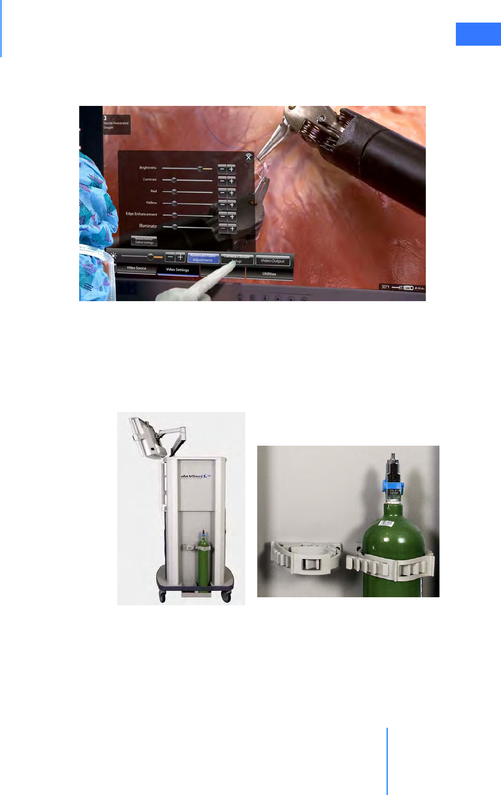
da Vinci® Si™
System Overview 2-16
DRAFT/PRE-RELEASE/CONFIDENTIAL
10/9/14
Touchscreen
The Vision Cart includes a touchscreen that is used to control system settings and view the
surgical image.
Figure 2.21 Assistant operating touchscreen
Tank Holders
The Vision Cart supports use of an insufflator with two tank holders on one side (Figure 2.22).
To accommodate various size tanks, the tank holders have adjustable straps above and the
lower bracket slides in and out after you loosen one screw on each side with a screwdriver. The
tank holders can support two tanks, each weighing up to 50 lbs. (22.32 kg).
Figure 2.22 Tank holders
_________________________________End of section______________________________
Tank strap adjustment
One tank installed
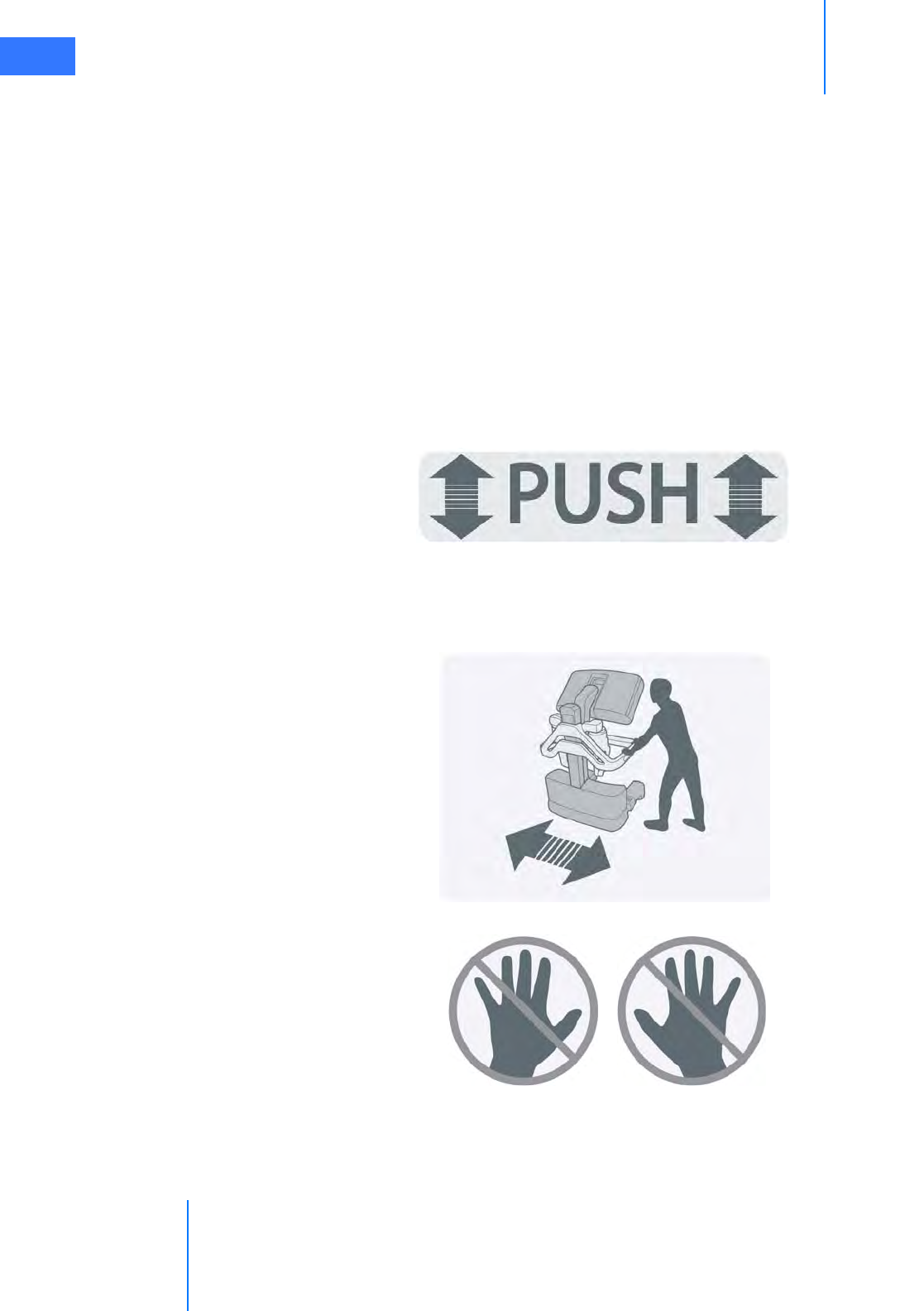
OR Configuration
da Vinci® Si™
3-1
DRAFT/PRE-RELEASE/CONFIDENTIAL
10/9/14
3OR Configuration
This chapter explains how to arrange da Vinci Si System components in the operating room for
maximum safety and ergonomic benefit. The following subjects are covered:
•3.1 Surgeon Console Positioning, page 3-1
•3.2 Patient Cart Positioning, page 3-2
•3.3 Vision Cart Positioning, page 3-6
3.1 Surgeon Console Positioning
The Surgeon Console is placed outside of the sterile field. Use the handles on either side of the
Surgeon Console (Figure 3.3) for moving or positioning. Labels say “PUSH” near the handles
for pushing on both sides.
Figure 3.1 “PUSH” label near handles on sides of Surgeon Console
Never push or pull the console from the back or the front. A label near the top of the pillar on
the back illustrates the correct way to move it. Separate “no hands” labels on both lateral
supports discourage placing hands there to move it.
Figure 3.2 Labels on rear of Surgeon Console
Do not move Surgeon Console from the back
Move Surgeon Console using handles on side
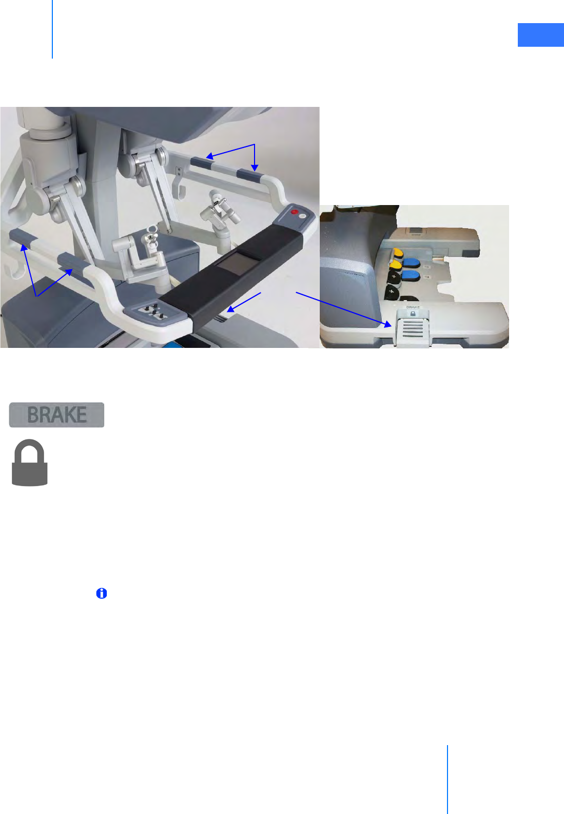
da Vinci® Si™
OR Configuration 3-2
DRAFT/PRE-RELEASE/CONFIDENTIAL
10/9/14
• When possible, orient the Surgeon Console so the Surgeon Console operator will have a
view of the operative field and a clear line of communication with the Patient Cart
operator.
Figure 3.3 Surgeon Console handles and brakes
•Brakes (indicated by “BRAKE” label) are located on each side of the base on the Surgeon
Console (Figure 3.3). The Surgeon Console should be locked once it is positioned for
surgery. Step on the brake pedal to apply that brake; the lock symbol will become visible
when the pedal is depressed, indicating the brake is applied. You need activate only one
brake to lower the footswitch panel. When possible, apply both brakes for best stability.
Step on the depressed brake to release it. Both brakes must be released to raise the
footswitch panel and enable Surgeon Console transport.
3.2 Patient Cart Positioning
Place the Patient Cart in the sterile field. We recommend two people to safely move the
Patient Cart: one to operate the motor drive (or push the cart when in neutral) and the other
positioned opposite to ensure the arms and cart do not accidentally hit anything.
Note: Use extreme care when moving or positioning the Patient Cart to ensure the arms
do not hit any objects. If an arm hits an object while the Patient Cart is being moved or
positioned, contact Intuitive Surgical Technical Support to have the Patient Cart
inspected for damage.
• You will need to dedicate a space in the room where the Patient Cart can be draped
before moving it into place for surgery. This should be an area where it will not easily
contact non-sterile objects nor impede traffic. Once the Patient Cart is draped and the
patient is positioned, prepared and ports are placed, use the Patient Cart motor drive to
move the cart into the sterile field (see Motor Drive Operation below).
Handles
Brakes
Handles
Brake
applied
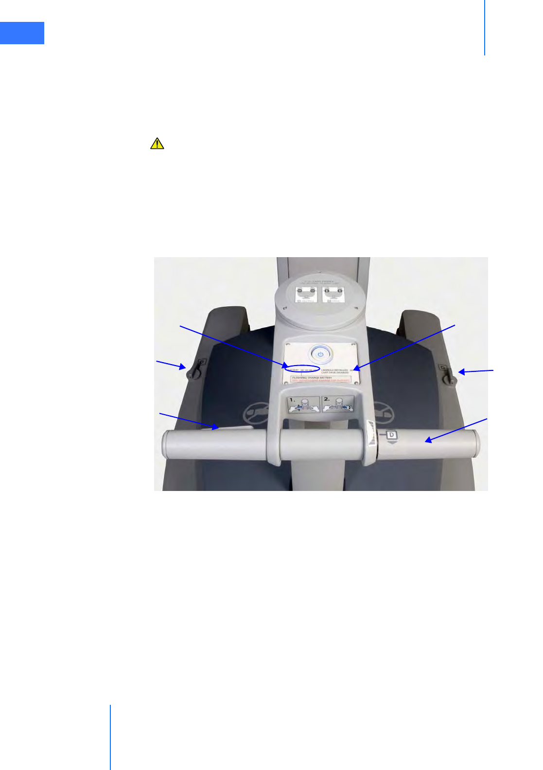
OR Configuration
da Vinci® Si™
3-3
DRAFT/PRE-RELEASE/CONFIDENTIAL
10/9/14
• The Patient Cart brakes are designed to automatically engage when the motor drive is
not in use, if the cart is not in neutral. When in neutral, the brakes do not engage
automatically until a cannula is installed.
Motor Drive Operation
CAUTION: Always use caution when moving large equipment.
The motor drive interface consists of the following:
• Throttle
• Throttle enable switch
•Shift switches
• Battery status indicators
• Cannula installed indicator
Figure 3.4 Patient Cart motor drive controls and indicators
Throttle
enable
switch Throttle
Shift switch
Shift switch
Battery status Cannula installed
indicator
indicators
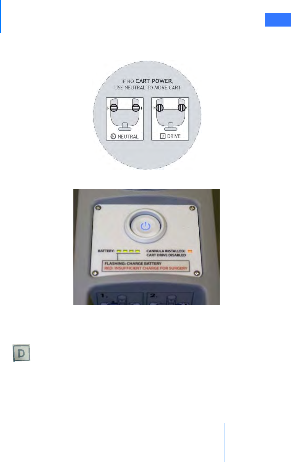
da Vinci® Si™
OR Configuration 3-4
DRAFT/PRE-RELEASE/CONFIDENTIAL
10/9/14
The top of the motor drive tiller has the label below (Figure 3.5). This label explains and shows
the N=Neutral and D=Drive positions for the motor drive shift switches. It includes the text, “IF
NO CART POWER, USE NEUTRAL TO MOVE CART”.
Figure 3.5 Label on top of motor drive tiller
Figure 3.6 Patient Cart power panel
To operate the motor drive:
1. First, make sure the Patient Cart is powered on. See 5.2 Powering On the System on page
5-2. See 5.1 Stand-Alone Mode on page 5-1, for instructions to power up only the Patient
Cart, when it is not connected to the Surgeon Console or Vision Cart.
2. Ensure the shift switches are in the drive position (see Figure 3.8).
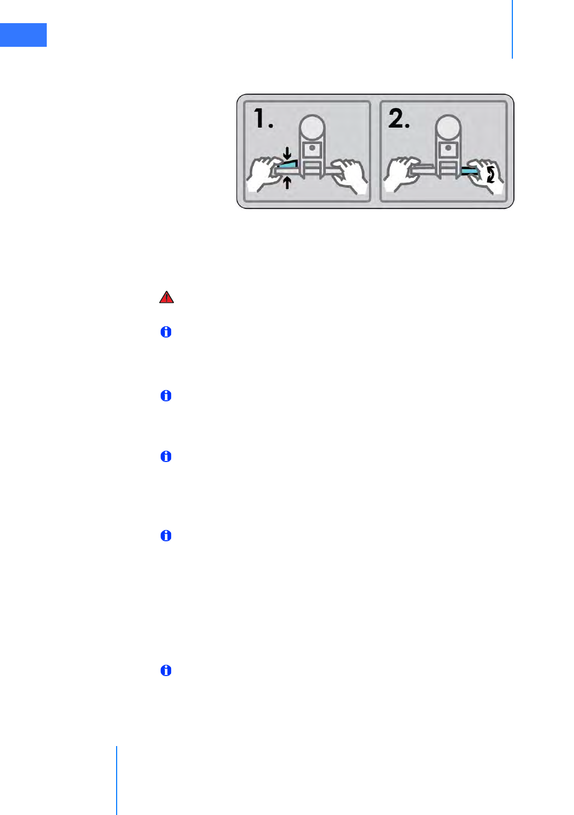
OR Configuration
da Vinci® Si™
3-5
DRAFT/PRE-RELEASE/CONFIDENTIAL
10/9/14
3. Hold the throttle enable switch and rotate the throttle away from you or towards you to
move in that direction. A label illustrates this two-part step:
Figure 3.7 Label: How to drive the Patient Cart
• The Cart Power button flashes green when the throttle enable switch is activated.
• Control the drive speed by how far you rotate the throttle.
4. To stop motorized movement, release the throttle enable switch.
WARNING: For patient safety, both shift switches must be kept in the drive (D) position
so that the motor drive remains engaged during surgery (see Figure 3.8).
Note: Use extreme care when moving or positioning the Patient Cart to ensure the arms
do not hit any objects. If an arm hits an object while the Patient Cart is being moved or
positioned, contact Intuitive Surgical Technical Support to have the Patient Cart
inspected for damage.
Note: For safety reasons, the motor drive will not engage whenever cannulae or
instruments are installed on the system. A yellow LED on the motor drive interface
labeled “Cannula Installed: Cart Drive Disabled” will indicate when cannulae or
instruments are installed and motor drive is non-operational.
Note: When operating on battery, the motor drive does not work if battery power is too
low. The battery status indicators show the amount of battery power. The lower part of
the motor drive interface explains the meaning of flashing or red BATTERY LEDs:
FLASHING: CHARGE BATTERY
RED: INSUFFICIENT CHARGE FOR SURGERY
Note: The Patient Cart battery should be adequately charged. If not, an error message
appears on the monitors. You can override the error if the Patient Cart is plugged into AC
power.
Shift Switches
In the event the Patient Cart should need to be moved without use of the motor drive (for
example, during a power loss), rotate both shift switches (Figure 3.8) to the neutral (N)
position. The cart can then be moved manually. Once you have finished moving the cart, place
both shift switches in the drive (D) position to set the Patient Cart brakes.
Note: The cart is capable of passing over thresholds of up to 10 mm high by 80 mm wide.
If a threshold is high enough that the motor drive is not able to drive over it, the cart can
be manually pushed over the threshold. Put the shift switches (Figure 3.8) in “N” for
neutral, and manually push the cart over the threshold.
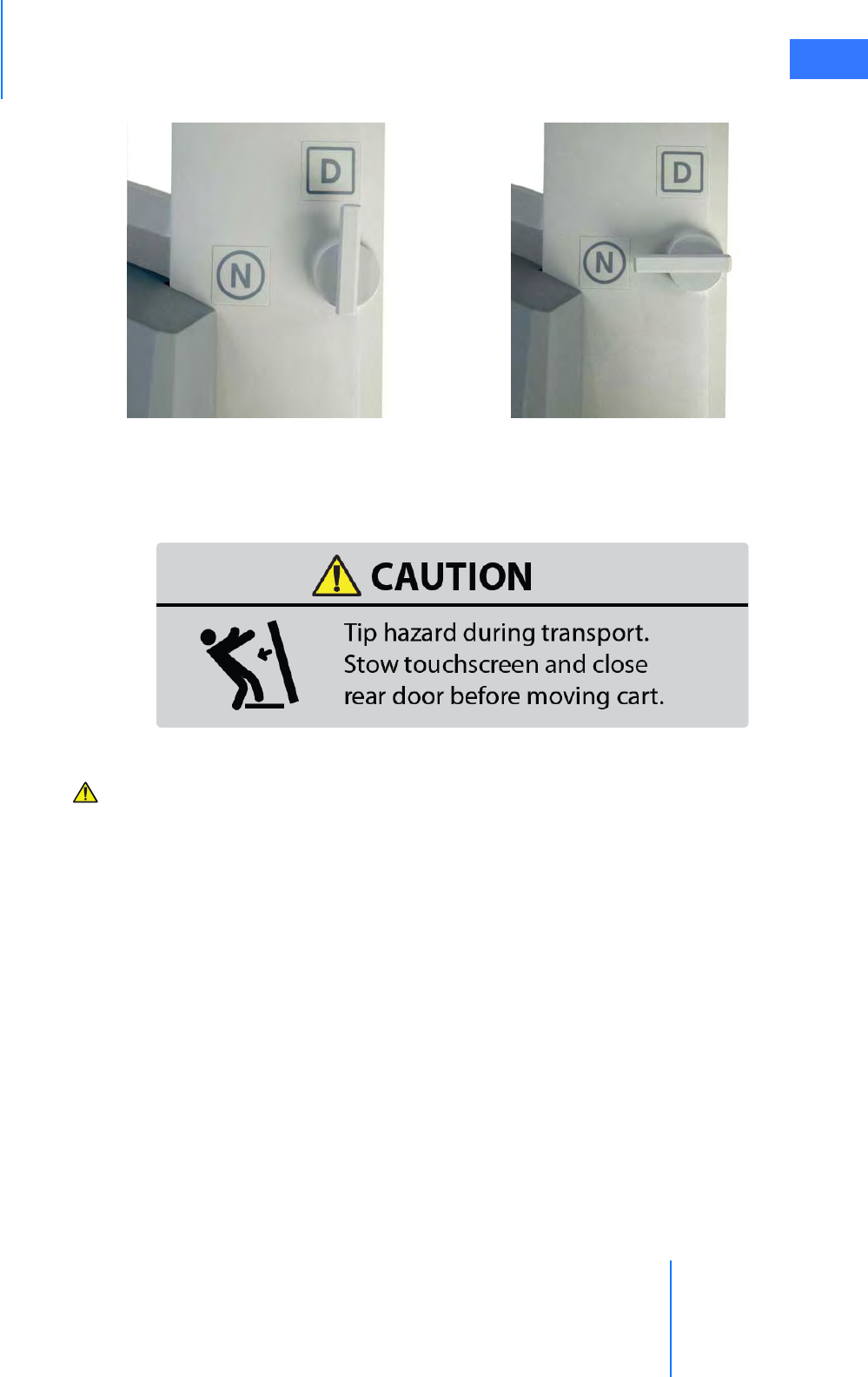
da Vinci® Si™
OR Configuration 3-6
DRAFT/PRE-RELEASE/CONFIDENTIAL
10/9/14
Figure 3.8 Patient Cart motor drive shift switches
3.3 Vision Cart Positioning
Figure 3.9 Tip hazard label on rear door of Vision Cart
CAUTION: Tip hazard during transport. Stow touchscreen and close rear door before
moving cart.
The Vision Cart is placed adjacent to the Patient Cart, just outside of the sterile field. Room is
provided on the Vision Cart shelves to place ancillary equipment (e.g. ESUs, insufflators).
Position ancillary equipment to allow the Patient Cart operator to easily view and access the
Vision Cart components and touchscreen.
• The Vision Cart should be close enough to the Patient Cart to allow unrestricted camera
cable movement during surgery.
Drive motor engaged (D) Drive motor disengaged (N)
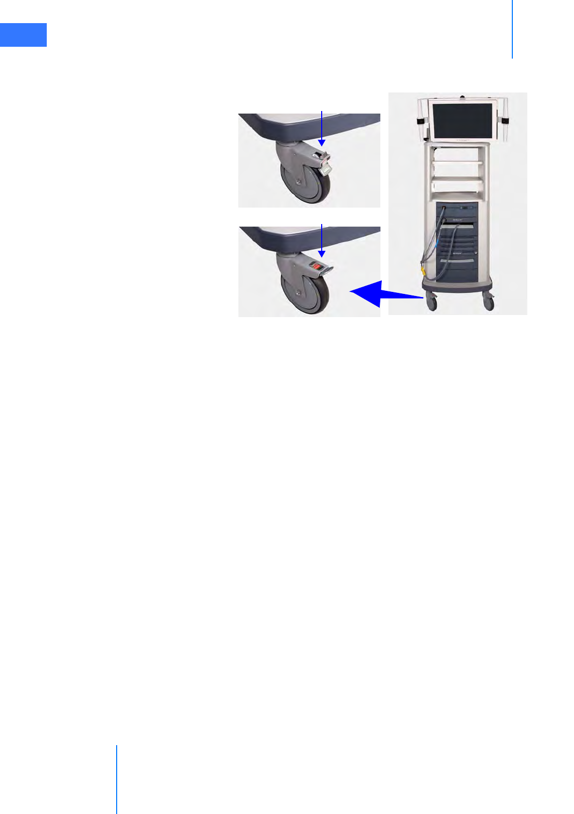
OR Configuration
da Vinci® Si™
3-7
DRAFT/PRE-RELEASE/CONFIDENTIAL
10/9/14
• Wheel locks are located on all wheels of the Vision Cart (Figure 3.10). These should be
locked after the cart is positioned for surgery.
Figure 3.10 Vision Cart wheel lock
_________________________________End of section______________________________
Unlocked
Push tab down to lock
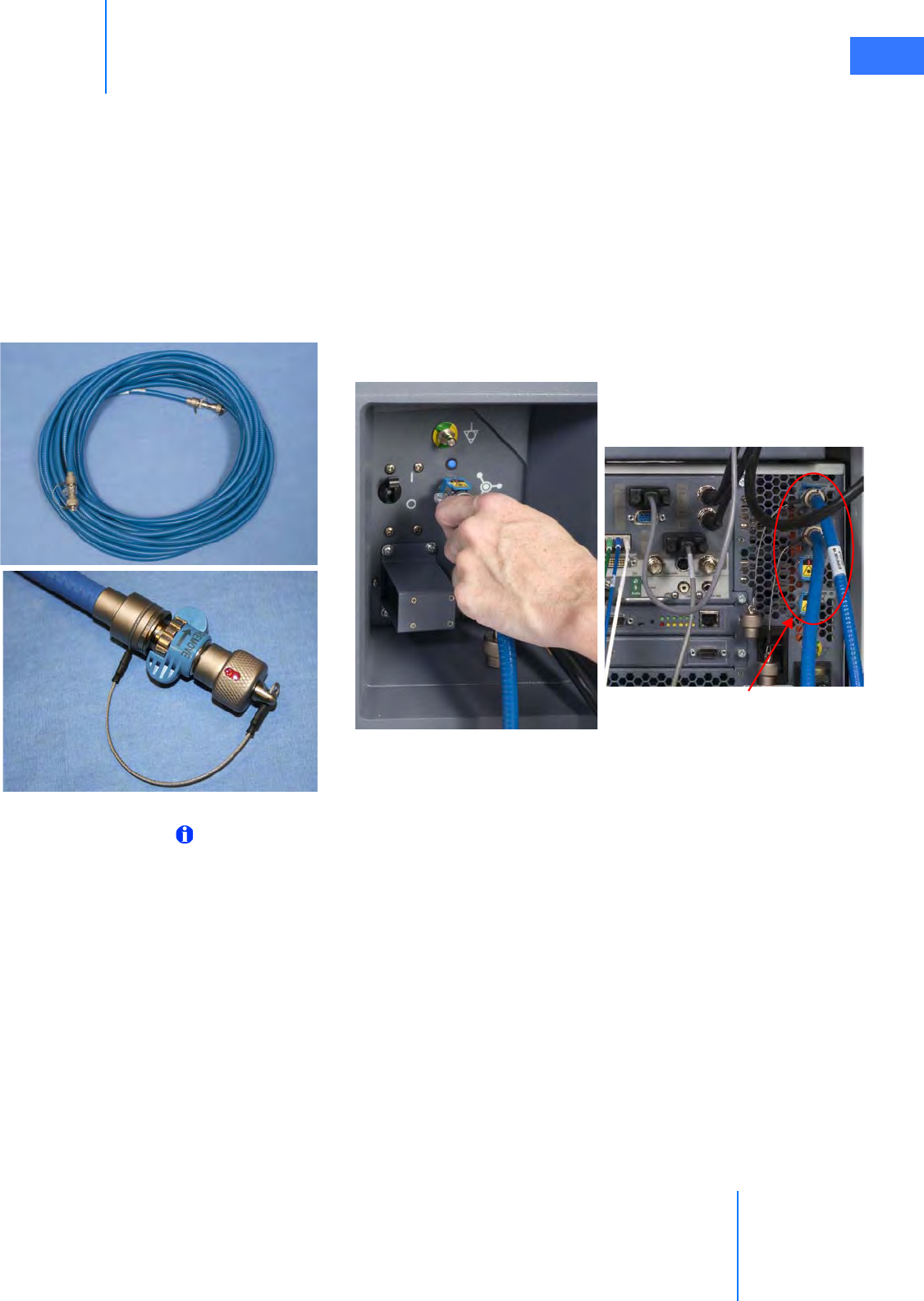
da Vinci® Si™
System Connections 4-1
DRAFT/PRE-RELEASE/CONFIDENTIAL
10/9/14
4System Connections
This chapter explains how to connect the individual da Vinci Si System components, including:
•4.1 Power Connections, page 4-2
•4.2 System Cable Connections, page 4-3
•4.3 Camera Head Cable Connections, page 4-6
•4.4 Auxiliary Device Connections, page 4-9
•4.5 Video and Audio Connections, page 4-11
Figure 4.1 Sample system cable and connections
Note: The only connections you should access on the back of the Vision Cart are the
power cords, blue system cables, auxiliary device cables, and audio/video cables as
described in this chapter. Other cables on the back of the Vision Cart should remain
connected at all times and should only be accessed by authorized ISI personnel.
Vision Cart Core Connections
Connecting Surgeon
Console
System cable
End cap on system cable

System Connections
da Vinci® Si™
4-2
DRAFT/PRE-RELEASE/CONFIDENTIAL
10/9/14
4.1 Power Connections
Connect the AC power cords of the Surgeon Console, Patient Cart, and Vision Cart to wall
outlets. (To support continued use of the da Vinci System in case of a site power failure, use
wall outlets [often red] supported by backup power.) Ensure adequate power is available at
each wall outlet according to the table below:
Note: Before first use, connect the Patient Cart to a wall outlet for at least 14 hours to
allow the backup battery to fully charge.
Note: The Patient Cart should remain plugged in when not in use to ensure that the
backup battery stays fully charged.
Note: Cooling fans on the Patient Cart and the Core (Vision Cart) run continually when
either is plugged into AC. This is part of normal operation.
Note: The power cord plug of each cart provides isolation from the supply mains.
Position equipment so that the power cord plugs can be accessed to isolate mains power
from the system.
CAUTION: Do not use an extension cord with any of the system components.
Table 4-1 System Power Cords and Power Requirements
System Component Cord Length Power Requirement Standby Power Draw
Surgeon Console
15 ft/4.6 meters 1000VA Continuous
8.4A at 115V~
4.2A at 230V~
95VA
0.8A at 115V~
0.4A at 230V~
Patient Cart
15 ft/4.6 meters 1000VA Continuous
8.4A at 115V~
4.2A at 230V~
75VA
0.6A at 115V~
0.3A at 230V~
Vision Cart
15 ft/4.6 meters 1500VA Continuous
12A at 115V~
6A at 230V~
145VA
1.1A at 115V~
0.55A at 230V~
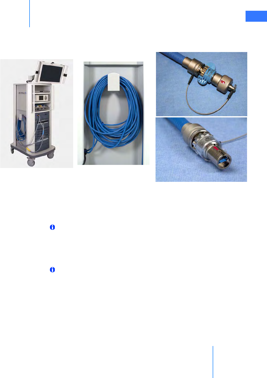
da Vinci® Si™
System Connections 4-3
DRAFT/PRE-RELEASE/CONFIDENTIAL
10/9/14
4.2 System Cable Connections
The da Vinci Si System cables (see Figure 4.2) are 20 m (65.6 ft) in length and should be kept
attached to the Vision Cart.
Figure 4.2 System cables
The system cables:
• Are identical and can connect to either the Surgeon Console or Patient Cart
• Pass video, audio, and data during system operation
• Are stored on the cable hook located on the side of the Vision Cart
Note: Once the system is connected and powered on, the system cables should not be
unplugged until the system has completely powered down. If the system cables become
unplugged during use, a non-recoverable fault will occur. To restore system
functionality, plug in the cable, remove all instruments, and restart the system. (See
page A-3 for more information on Restarting the System During a Procedure due to a
non-recoverable fault.)
Note: The system cables have a fiber-optic core. Care should be taken to avoid bending
the cable, as kinks can damage the cable and may prevent system operation. The
minimum safe bend radius is 1 inch (2.54 cm). Take care to avoid stepping on the cable,
since this can damage it.
End cap on system cable
Uncapped end of cable
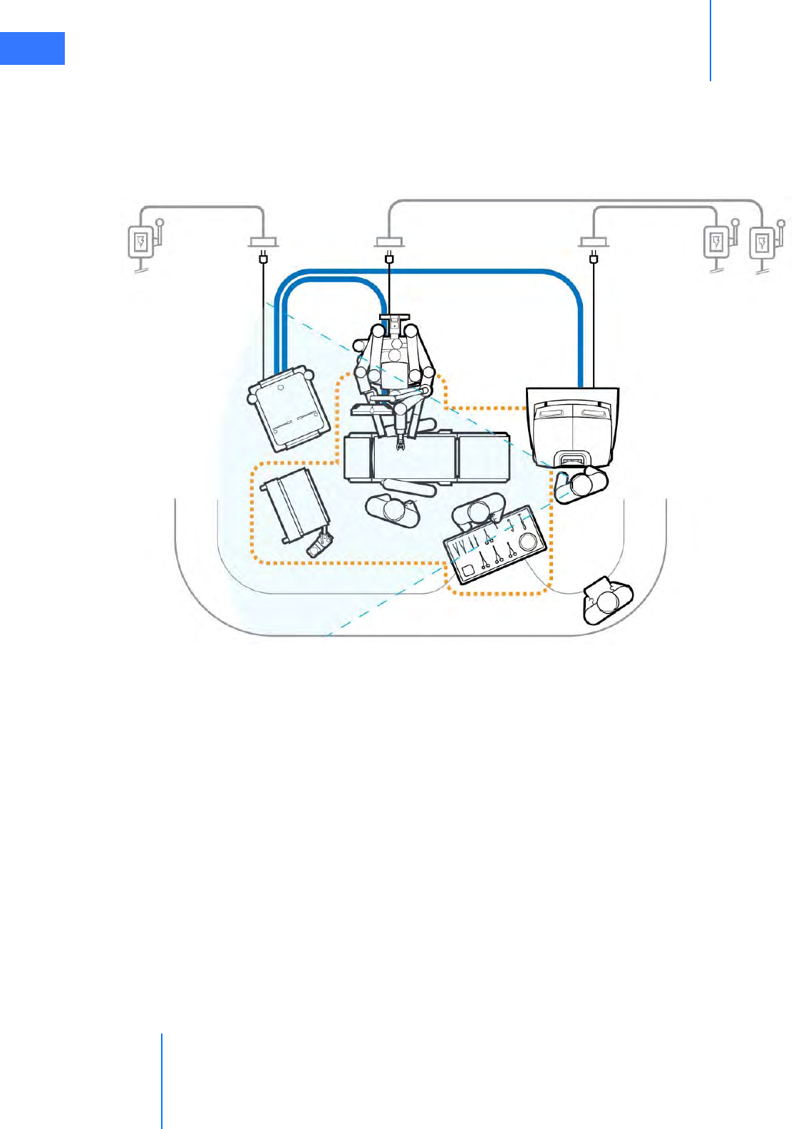
System Connections
da Vinci® Si™
4-4
DRAFT/PRE-RELEASE/CONFIDENTIAL
10/9/14
System Cable Layout
The cables should be arranged so that they are out of the path of OR traffic, including other
equipment, to avoid damaging the cables or creating an obstacle or hazard. The location of
the cables should also facilitate easy movement of the Patient Cart between its preoperative
(draping) and intraoperative locations.
Figure 4.3 Laying out the system cables
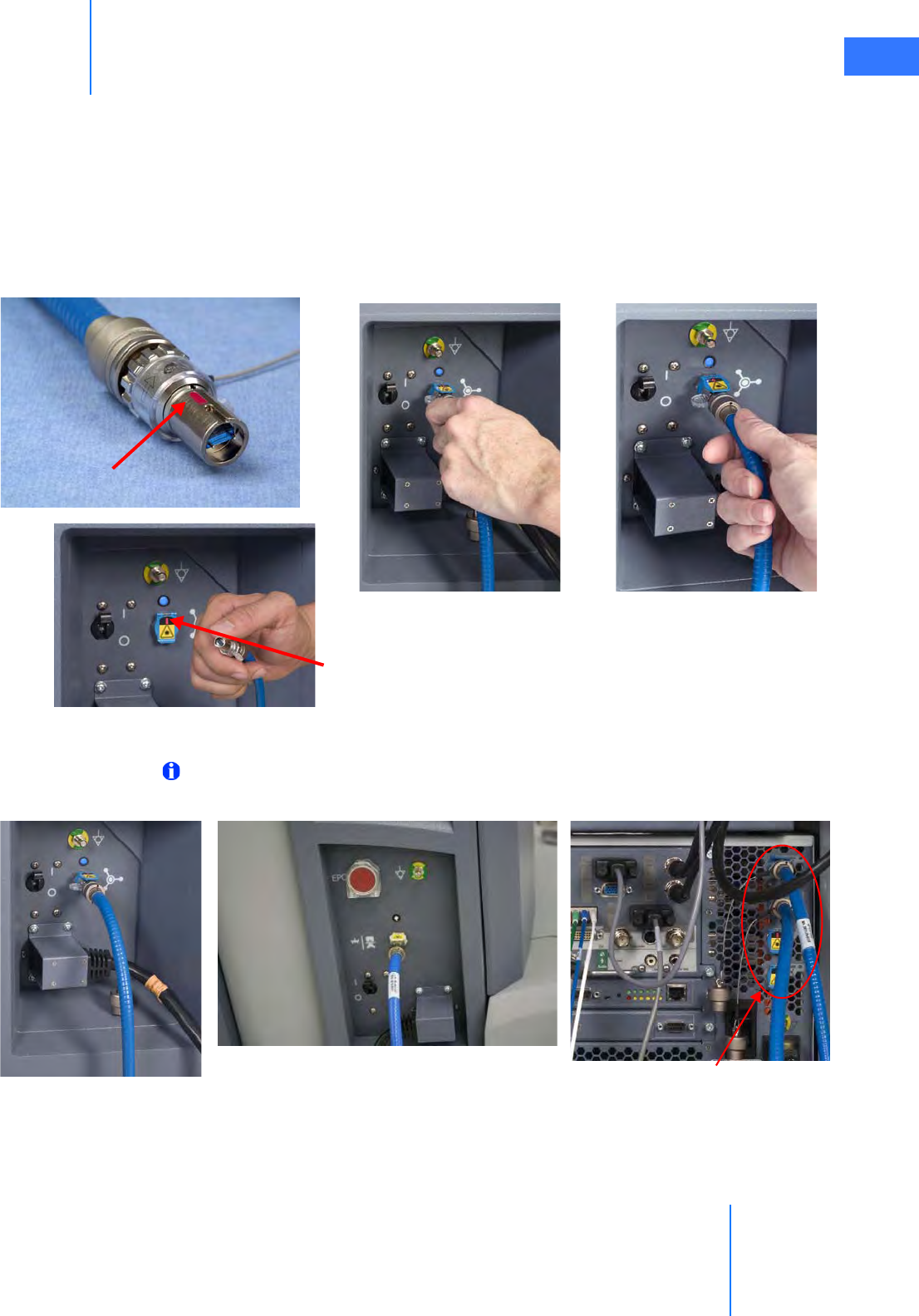
da Vinci® Si™
System Connections 4-5
DRAFT/PRE-RELEASE/CONFIDENTIAL
10/9/14
How to Connect System Cables
1. Remove the cables' protective caps, inspect the cable connectors and system receptacle
for debris or bent pins. The system receptacles have protective covers you must open.
2. Connect the system cables between the components as shown in Figure 4.3. To connect
the cables, line up the red dot on the cable connector with the red dot on the matching
receptacle, flip up the receptacle cover and insert the connector. You should hear an
audible click when the cable engages properly. Gently pull on the connector to verify the
cable is fully seated.
Figure 4.4 Connecting system cable to Surgeon Console
Note: The protective metal caps attached to each system cable should be installed on
cable ends at all times when not connected to the system.
Figure 4.5 System connections
Red alignment mark
1. Observe red mark
and align
2. Flip up receptacle
cover & insert
3. Tug gently to assure
connection
Patient Cart connection Vision Cart Core connections
Surgeon Console connection
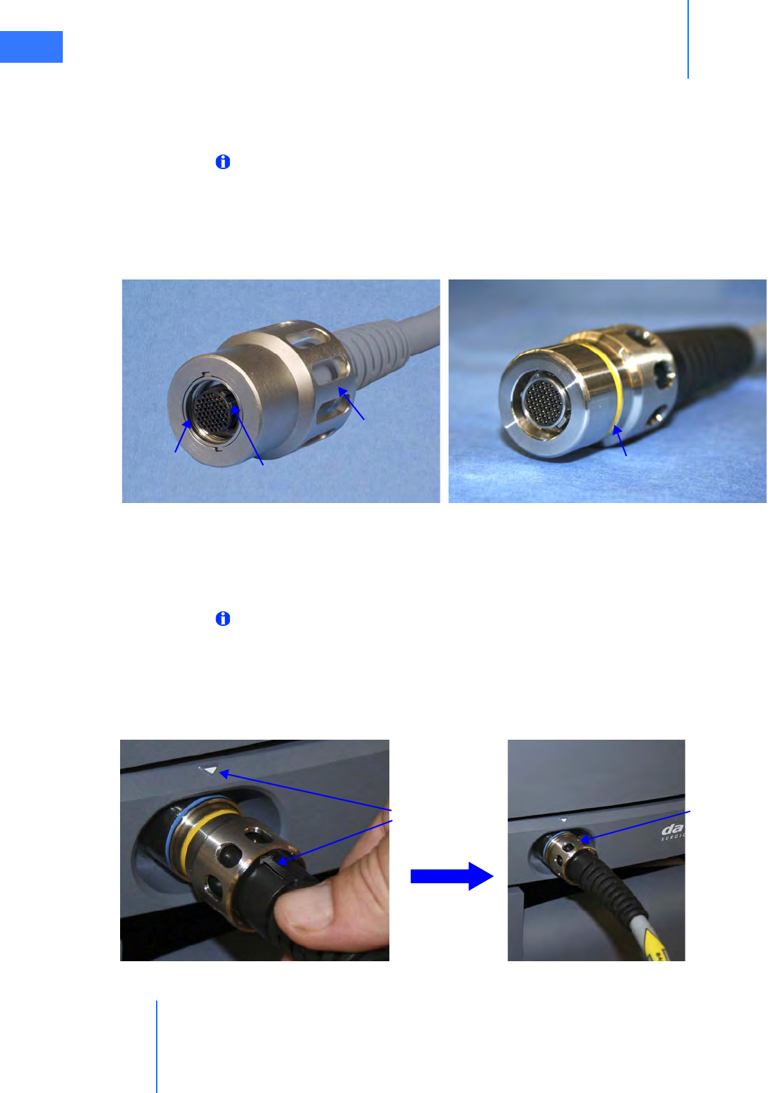
System Connections
da Vinci® Si™
4-6
DRAFT/PRE-RELEASE/CONFIDENTIAL
10/9/14
4.3 Camera Head Cable Connections
The camera head has two cables: one for video and one for illumination. Both the camera
head video cable and the light guide cable are 5.75 m (18 ft 6 in) long.
Note: Intuitive has shipped da Vinci Si Systems with two different kinds of camera head
video cable, which can be readily distinguished by having either black ends or gray
ends. This section addresses use of both kinds of cable. The cables and their connectors
on the camera head and CCU are not cross-compatible, that is, a cable with black ends
will not work with a system designed to work with a cable that has gray ends. Users must
not attempt to switch camera cables to an incompatible system.
Figure 4.6 Ends and connectors of each kind of camera cable
Connecting the Camera Cable
Although the steps are basically the same for the two kinds of camera cable, note the
distinguishing details that pertain to cables with black or gray ends called out in this section.
Note: The camera cable with black ends has a yellow ring on the (male) CCU connector
that must be paired only with the (female) receptacle on the CCU, which has a blue ring.
Follow these steps to connect the camera cable (see Figure 4.7).
1. Attach the camera cable to the receptacle on the Camera Control Unit (CCU). The
connector is keyed. Therefore, to successfully insert the connector, you must match the
alignment arrows on the cable connector and the top of the CCU receptacle as shown.
Figure 4.7 Camera cable connection to CCU
Camera cable with gray ends, CCU connector Camera cable with black ends, CCU connector
Nut to secure
connector
Keyed connector requires
correct alignment
Threaded
inside
Yellow ring to be covered when
nut properly tightened
Match
alignment
arrows
Tighten nut
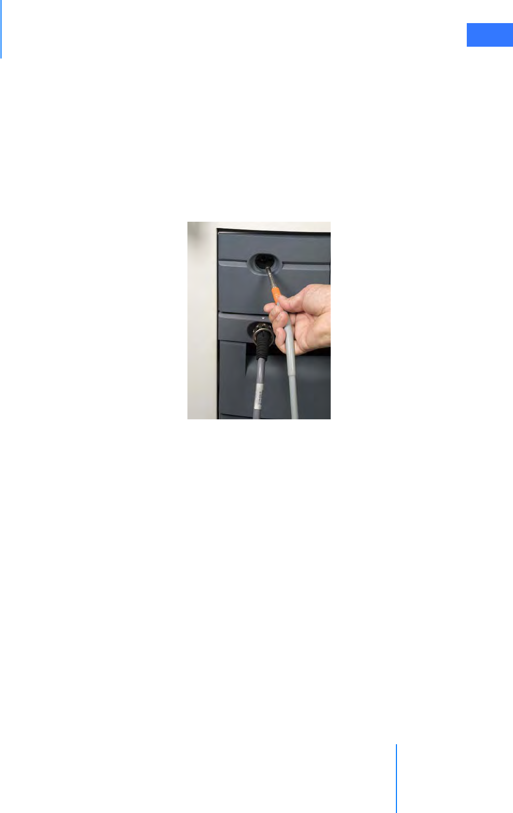
da Vinci® Si™
System Connections 4-7
DRAFT/PRE-RELEASE/CONFIDENTIAL
10/9/14
2. Carefully align and direct the connector straight in; begin to tighten the nut only when
you are certain it is not cross-threaded.
3. Once started properly, tighten (clockwise) the large metal nut around the inserted cable
end. It is threaded so you can hand tighten the connector and secure it. For the cable with
black ends, to ensure a good connection, tighten the nut until you can no longer see any
part of the yellow ring around the base of the nut.
Connecting the Light Guide Cable
4. Insert the light guide cable connector into its receptacle on the Illuminator as shown. You
will hear a click when the connector is fully inserted. Gently pull on the light guide
connector to confirm that the connector is fully inserted into the receptacle.
Figure 4.8 Connecting the light guide cable
Care of Camera Cables
The fiber optic light guide cable and camera cable are susceptible to damage from kinking or
crushing or contamination to their connectors if disconnected, all of which degrades light
transmission, and could diminish video quality or even lead to cable failure. To preserve the
life of your cables, follow these guidelines to care for them.
• Leave both camera cables connected at both ends when not in use. This protects the
connectors and receptacles from contamination.
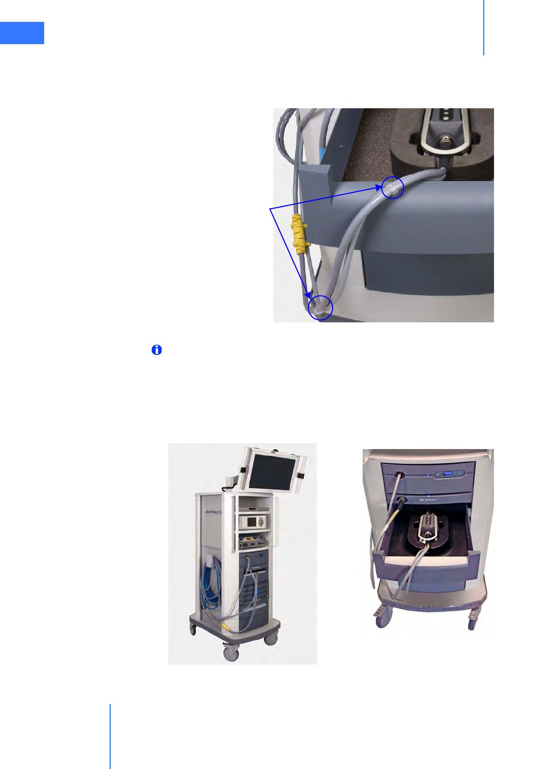
System Connections
da Vinci® Si™
4-8
DRAFT/PRE-RELEASE/CONFIDENTIAL
10/9/14
• Use the S-hooks provided with the camera cables to bind the light guide and camera
head video cable together, as shown below. The S-hooks keep both cables together and
untangled, which helps you to handle and store them without coiling them too tightly or
kinking them.
Figure 4.9 S-hooks to hold camera cables together
Note: If you need additional S-hooks, you can acquire them from Intuitive Surgical and
install them yourself. Contact Intuitive Surgical Customer Service.
• Store the camera head in its custom cutout in the Vision Cart drawer below the CCU, and
coil the camera cable pair loosely, and hang the excess cable on the hook on the side of
the Vision Cart. The hook on the side is large enough to accommodate both the blue
system cable and the camera cables. See Figure 4.10 for an example.
Figure 4.10 Store camera cables connected
Installed
S-hooks
Connected camera head in storage drawer

da Vinci® Si™
System Connections 4-9
DRAFT/PRE-RELEASE/CONFIDENTIAL
10/9/14
4.4 Auxiliary Device Connections
WARNING: Do not plug additional equipment into the same wall outlet as the Vision
Cart. This could potentially overload the circuit.
Note: If combinations of the installed energy instruments or connected ESUs make
mapping of energy pedals ambiguous, the system will not map nor activate the pedals
for that energy type. For instance, you cannot be in simultaneous energy control of two
energized instruments of the same type (for example, bipolar and bipolar). This means
that if a surgeon is actively controlling two bipolar instruments at the same time with
the right and left master controllers, then he/she will not be able to activate energy.
Compatible electrosurgical units (ESUs) can be actuated after connecting the appropriate
energy activation cable to any of the auxiliary connectors on the back of the Core. You can
attach up to 3 ESUs at a time. Cables are color-coded by ESU model. See the Instruments and
Accessories User Manual (PN 550675) for a complete list of cables.
Figure 4.11 Representative Auxiliary Device Cable
Figure 4.12 Representative ESU setup
CAUTION: Ensure that only compatible ESUs are connected to the da Vinci Si System.
Refer to the Instruments and Accessories User Manual (PN 550675) for a complete list of
compatible ESUs. Performance of cables or accessories other than those specified in the
Instruments and Accessories User Manual cannot be guaranteed. Any damage to the
system resulting from using an incompatible ESU will not be covered under warranty.
Connect to ESU
Connects to
da Vinci Si Core
da Vinci Si
Core
Gyrus
G400
Covidien
Force Fx
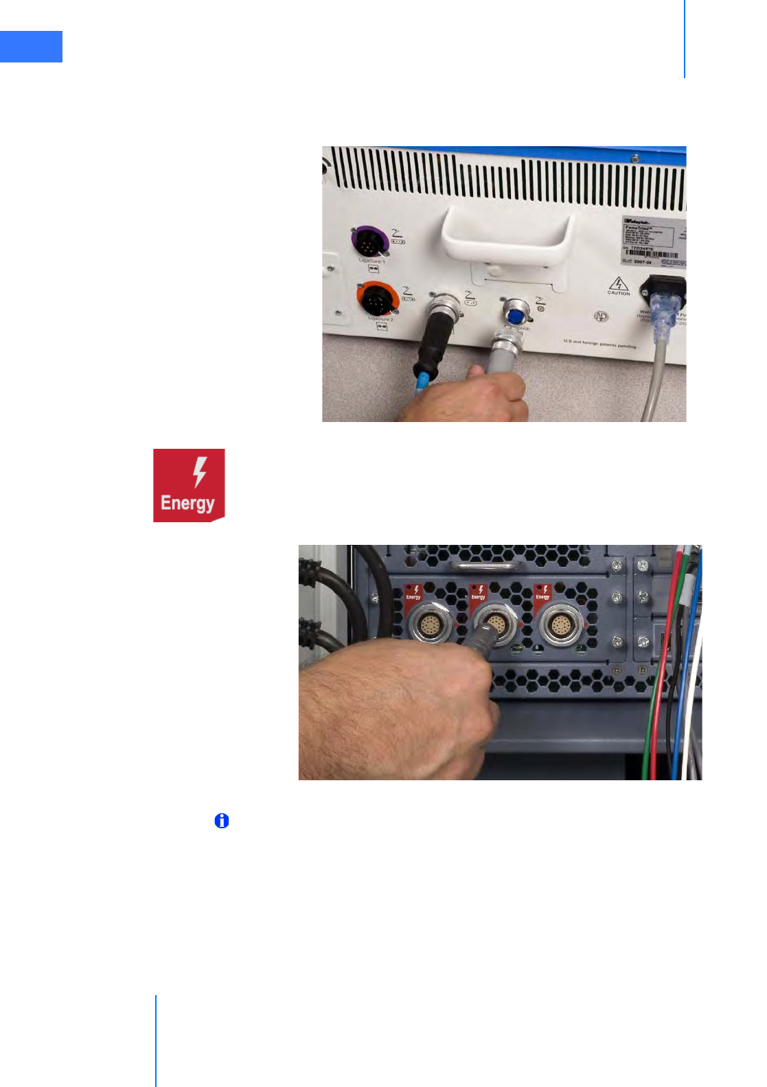
System Connections
da Vinci® Si™
4-10
DRAFT/PRE-RELEASE/CONFIDENTIAL
10/9/14
To connect an auxiliary device (for example, an ESU) to the system:
1. Plug the auxiliary device end of the cable into the corresponding channel(s) on the
device. Tighten the screw lock completely to ensure that the cable is fully connected.
Figure 4.13 Auxiliary device connection (back of ESU)
2. Plug the system end of the cable into any of the three Energy receptacles on the back of
the Core (Figure 4.14). Align the red dot on the cable connector with the red dot to the
right of the receptacle. You should hear an audible click when the cable engages
properly. Gently pull on the cable connector to verify that the cable is fully seated. When
the ESU and system are turned on, the corresponding LED indicator will turn on.
Figure 4.14 Auxiliary device connections (back of Core)
Note: If the energy activation cable is unavailable or non-functional, the generator
manufacturer's footswitch may be used. In this case, the system will not provide any
feedback to the user in the Surgeon Console viewer.
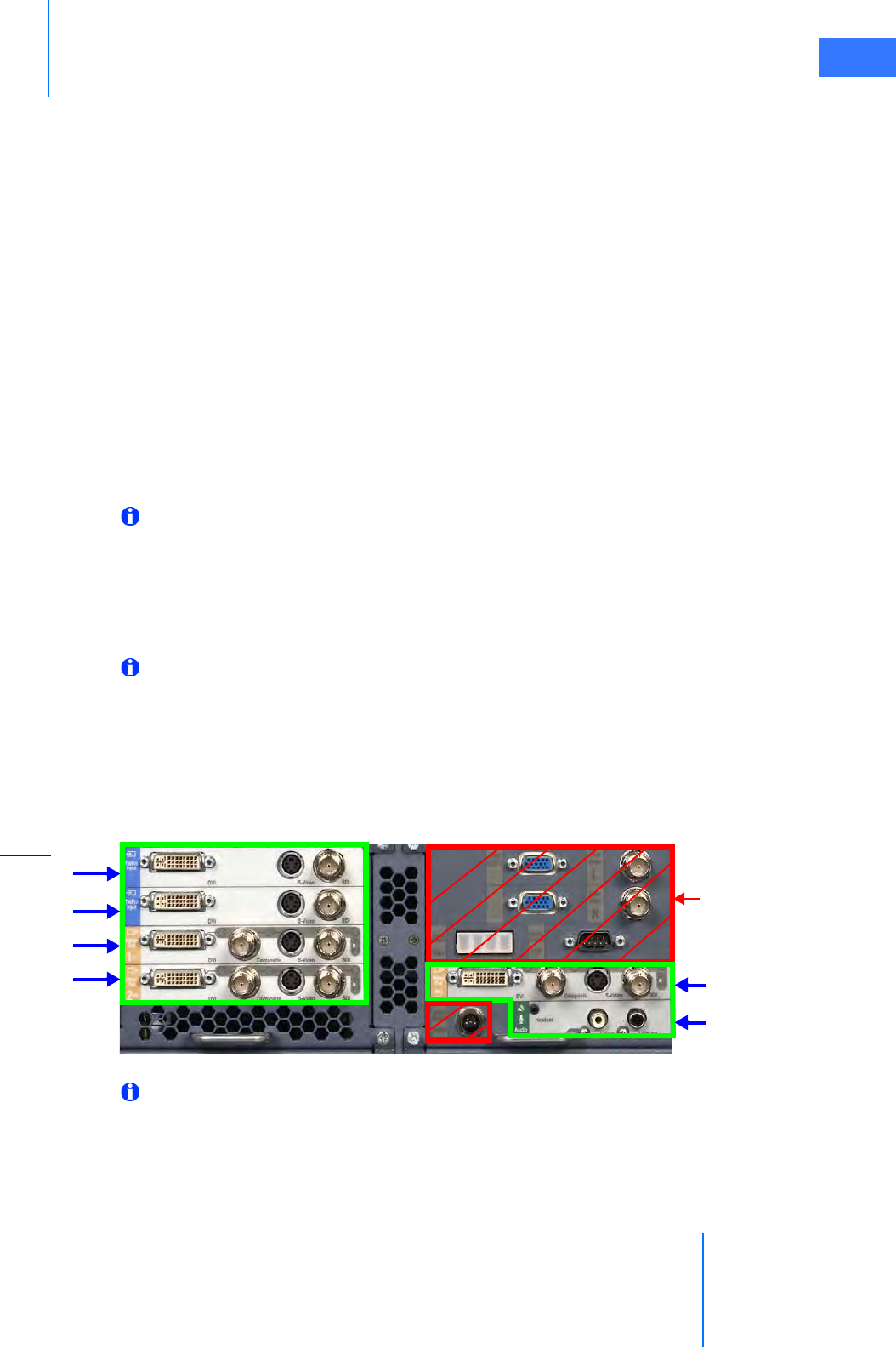
da Vinci® Si™
System Connections 4-11
DRAFT/PRE-RELEASE/CONFIDENTIAL
10/9/14
Troubleshooting: EndoWrist Cautery not Responding to
Footswitch
1. Check cable connections between the instrument and the generator.
a. Check the patient return electrode (if necessary).
b. Check AC power connection to the generator.
c. Check cable connection between the generator and the da Vinci Si System to ensure
proper cable orientation.
2. Power on the generator.
3. If the problem persists, power off the generator.
a. Attach the generator to the manufacturer’s external footswitch.
b. Power on the generator.
4. If the problem persists, contact customer service for assistance: U.S. 800-876-1310,
International +800 0821 2010 or +41 21 821 2020.
4.5 Video and Audio Connections
Note: The four Core video in and out bays shown on the left in Figure 4.15 (in green box,
the TilePro Inputs and Video Out bays 1 and 2) are not available by default; they are
made available in conjunction with optional upgrades, for example, with purchase of a
second console to support dual console surgery. Video Out bay Aux and the Audio
In/Out bay, at lower right, are available by default. The default TilePro Inputs are
available on the back of the Surgeon Console.
Note: Each input and output bay supports only one video format at a time.
The back of the Core supports up to 6 auxiliary connection bays: 2 for video input, 3 for video
output and 1 for audio input/output. Each bay has 3-4 connectors, but supports use of only
one connection at a time. A connection panel on the back of the Surgeon Console supplies
the default TilePro Inputs. Additionally, the back of the Camera Control Unit has two
component video outputs. For additional information, see the Core Connections Diagram on
page H-5.
Figure 4.15 Video and audio connections (back of Core)
Note: See H.5 Video Patch Panels in Appendix H: System Specifications for detailed
information regarding video connections.
TilePro Input (L)
Video Out bay 1
Video Out bay 2 Video Out bay Aux
Audio In/Out
TilePro Input (R)
Not for
connection
by users
Optional
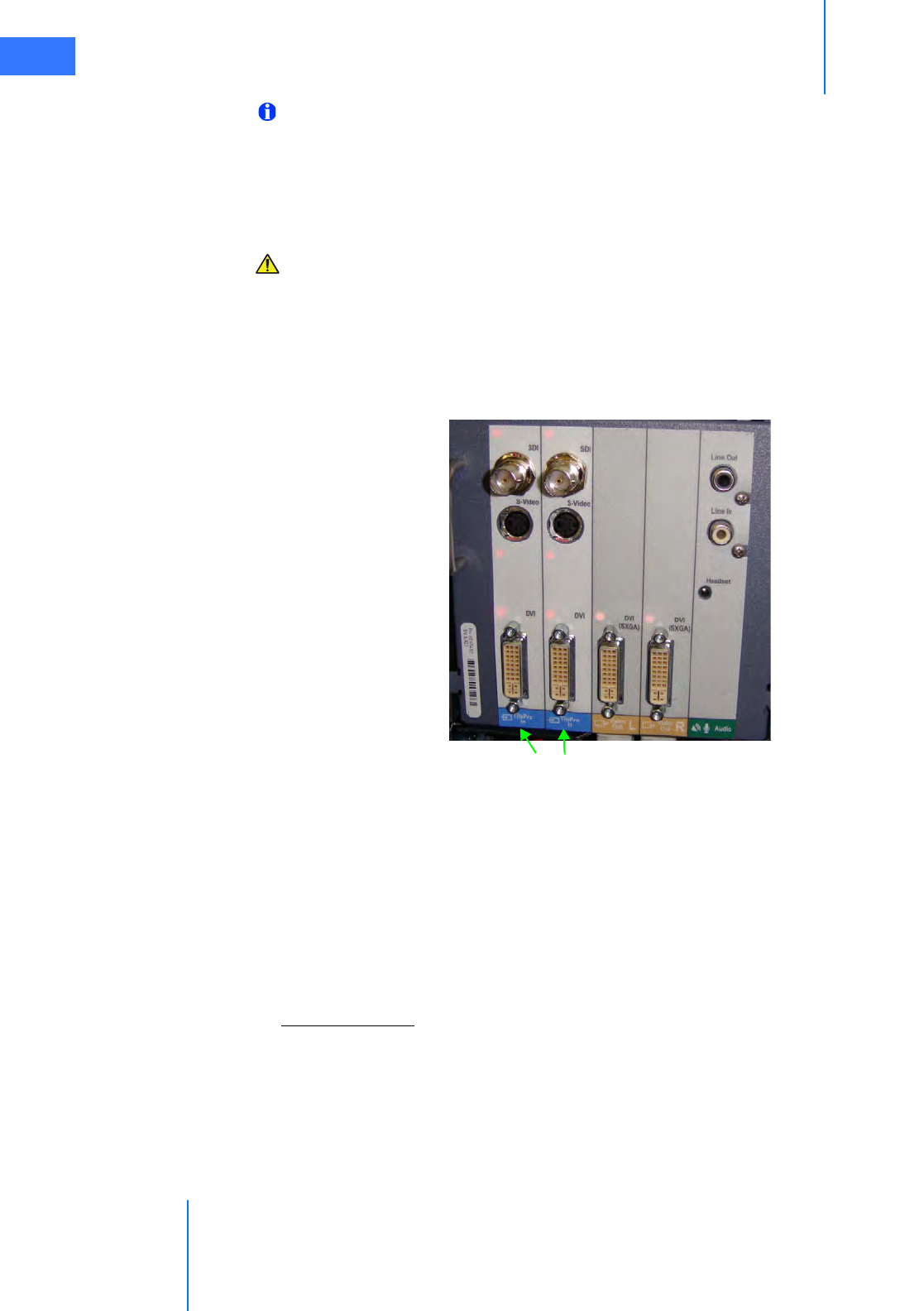
System Connections
da Vinci® Si™
4-12
DRAFT/PRE-RELEASE/CONFIDENTIAL
10/9/14
Note: Connectors on the Core (and other components on the Vision Cart) labeled with
gray text on a dull background, as those indicated by red boxes in Figure 4.15 above, are
connected as necessary by authorized ISI personnel when they install and/or service the
system. Therefore no instructions are provided for connecting them in this user manual,
although the labels themselves are described in Appendix G: Symbols, Icons and Text
Messages Reference. Do not unplug any of these connections.
CAUTION: To avoid an electrical hazard, do not touch the patient while touching any
connectors at the same time.
Surgeon Console Connections (TilePro)
Two video input bays (Figure 4.15) are provided on the back of the Surgeon Console to enable
multi-image mode (TilePro) in the Surgeon Console. Each video input bay is capable of
accepting a single DVI, HD-SDI, or S-Video signal.
Figure 4.16 Connections on back of Surgeon Console
•The Video Out L and Video Out R bays on the Surgeon Console support transmission of
the left and right eye video seen in the Surgeon Console via DVI connection. These bays
operate independently from the optional Video Out 1 and Video Out 2 bays on the Core.
The latter are available only with optional upgrades and support video output that the
user can program via the touchscreen (see Video Output on page 7-19).
•The Audio bay supports transmission of Surgeon Console audio with connectors for RCA
output (LIne Out), RCA input (Line In) and a 2.5 mm input/output headset jack
(Headset).
TilePro, 2D and 3D
TilePro multi-image mode enables the surgeon to see up to two additional video inputs in the
stereo viewer of the Surgeon Console, along with the live endoscopic video image. Most video
sources connect using only one input connector, which yields a two-dimensional (2D) image.
•3D TilePro: To display a 3D TilePro video source in the stereo viewer, connect a
compatible (stereo) video source to both the TilePro (L) and (R) connectors at once and
select 3D on the touchpad (see Figure 10.18 Display Preferences on page 10-15).
TilePro Input (L), (R) Video Out L, R Audio
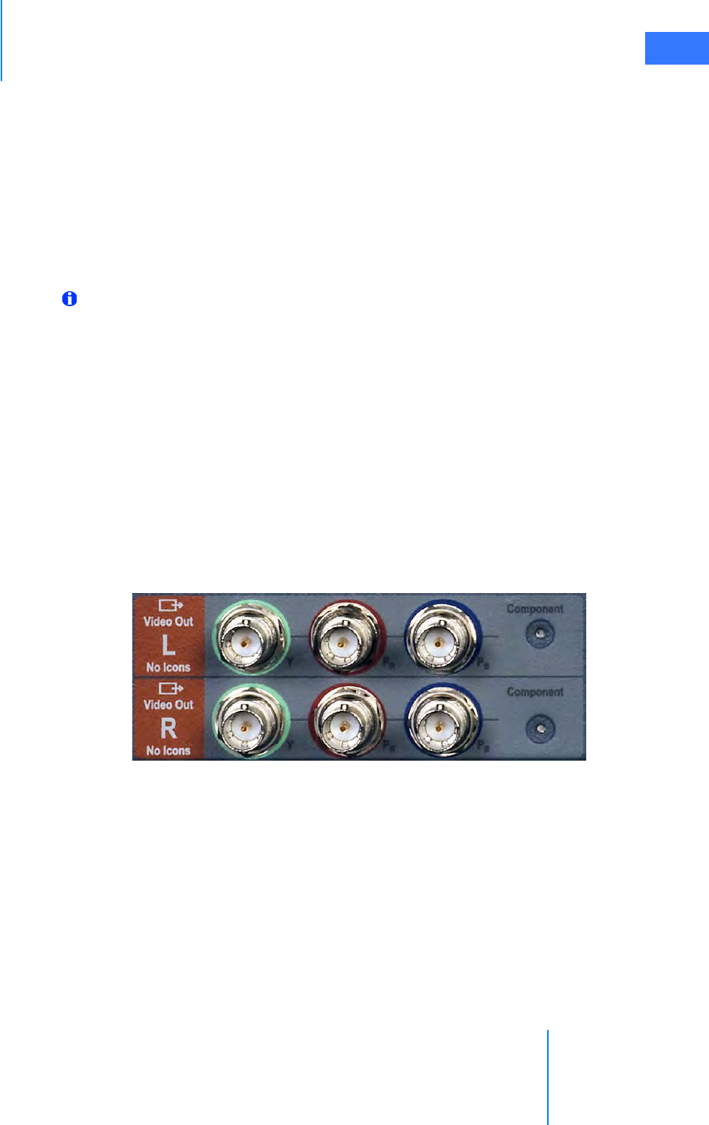
da Vinci® Si™
System Connections 4-13
DRAFT/PRE-RELEASE/CONFIDENTIAL
10/9/14
• If an upgrade has been installed that makes available the optional TilePro Input bays on
the Core (see Figure 4.15), you can use either set of TilePro inputs, but not more than two.
The system automatically checks for TilePro connections in order: first on the Core (if
present), then on the Surgeon Console. The Core TilePro inputs take precedence if they
are in use.
Core Video Outputs
The Core supports up to three video output bays (Figure 4.15). Video output from all three
includes the icons and text messages displayed in the Surgeon Console. Each video output
bay supports a single DVI, HD-SDI, S-Video, or Composite signal.
Note: Video Out bays 1 and 2 are not available by default; they are made available in
conjunction with optional upgrades, for example, with purchase of a second console to
support dual console surgery. Only the Video Out Aux bay is available by default.
Core Audio Inputs and Outputs
Three connectors are provided on the audio bay (Figure 4.15).
• 2.5 mm input/output headset jack
•RCA input
•RCA output
Camera Control Unit Video Outputs
Two video outputs are available on the back of the Camera Control Unit. The left-eye (L) and
right-eye (R) video outputs provide the surgical image without icons or text messages. This is
component video, made up of Y (green port), PR (red port) and PB (blue port).
Figure 4.17 Video connections (back of CCU)
Troubleshooting: Audio not Functioning
1. Power off the system.
2. Check audio cables for debris or bent pins.
3. Reconnect all audio cables.
4. Power on the system.
a. Check audio on the Vision Cart and Surgeon Console. Adjust volume if needed.
5. If the problem persists, contact customer service for assistance: U.S. 800-876-1310,
International +800 0821 2010 or +41 21 821 2020.
_________________________________End of section______________________________
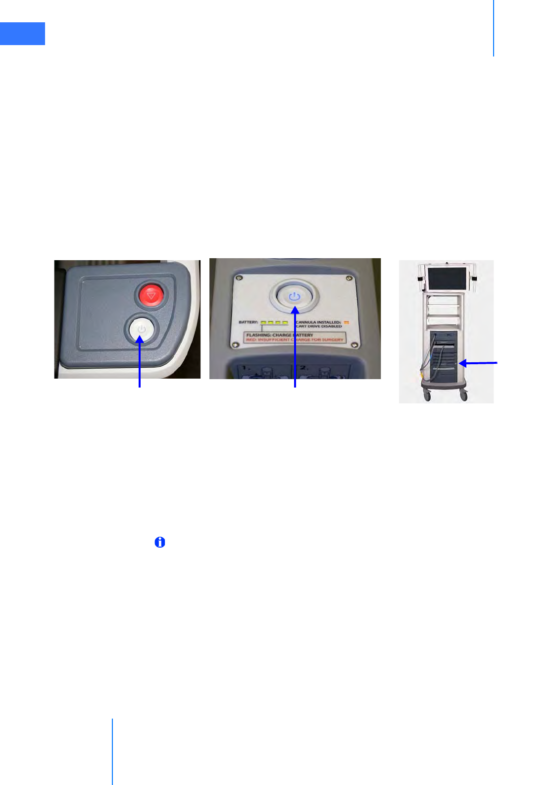
Startup
da Vinci® Si™
5-1
DRAFT/PRE-RELEASE/CONFIDENTIAL
10/9/14
5Startup
This chapter explains how to power up the da Vinci Si System components. It will cover the
following topics:
•5.1 Stand-Alone Mode, page 5-1
•5.2 Powering On the System, page 5-2
•5.3 Startup Sequence, page 5-5
•5.4 Preparing the Patient Cart for Draping, page 5-6
•5.5 Stow Position, page 5-7
5.1 Stand-Alone Mode
Figure 5.1 System power buttons
The Power buttons on the Vision Cart, Patient Cart and Surgeon Console are lit amber when in
standby mode (connected to AC power but not powered on), blue when powered on. The
Power buttons are not lit at all when not connected to AC power.
The Surgeon Console, Patient Cart and Vision Cart can all be powered on individually, known
as stand-alone mode.
While the Surgeon Console is in stand-alone mode, you can adjust the ergonomic controls. No
touchpad functions are available.
Note: To operate in dual console mode (using a second Surgeon Console--see 10.5 Dual
Console Surgery), simply plug the second console’s system cable in one of the available
Fiber ports on the back of the Core. No other connection is necessary, except of course to
plug in the Surgeon Console to a dedicated AC power outlet. The second Surgeon
Console behaves just as the first with respect to power operations, as described in this
section.
While the Patient Cart is in stand-alone mode and not connected to the Vision Cart, the arm
LEDs do not provide any feedback and system accessories do not engage. You can use the
Patient Cart motor drive and clutch buttons when not connected to the Core nor to AC power.
While the Vision Cart is in stand-alone mode, all vision system functions are available (for
example, video sources, auto-calibration, white balance, etc.).
Surgeon Console
power button
Patient Cart
power button
Vision Cart
power button

da Vinci® Si™
Startup 5-2
DRAFT/PRE-RELEASE/CONFIDENTIAL
10/9/14
1. To power on the Surgeon Console or Vision Cart in stand-alone mode, make sure the
power cord is plugged in, and press the Power button (Figure 5.1).
2. To power on the Patient Cart in stand-alone mode, press the Power button on the Patient
Cart (Figure 5.1). The Patient Cart does not need to be plugged in for stand-alone mode.
Note: Each of the Surgeon Console, Patient Cart and Vision Cart has a mains circuit
breaker switch on its rear that must be in the on position (indicated by “I” near each
switch) for that subsystem to power on. The Core, Illuminator and Camera Control Unit
(CCU) each also has its own component power switch on the back that must be in the on
position for that component to power on. All of these subsystem and component power
switches are intended to be left in the on position, and used only in special
circumstances like those described below under Addressing Anomalous Power
Behavior, page 5-2.
5.2 Powering On the System
When the Surgeon Console, Patient Cart, and Vision Cart are fully connected and plugged into
AC power, you can power on all of them by pushing any of the system Power buttons.
Note: If any of the individual components are in stand-alone mode and you connect the
system cables, the system will power itself on.
Note: System cables may be connected at any time, but once connected, cannot be
unplugged until the system has been completely powered down.
Note: The Patient Cart battery should be adequately charged. If not, an error message
appears on the monitors. You can override the error if the Patient Cart is plugged into AC
power.
Addressing Anomalous Power Behavior
Anomalous and rare circumstances may result in the da Vinci System as a whole, or one of the
Patient Cart, Vision Cart or Surgeon Console separately, to fail to power on normally, or to
undergo an automatic, controlled power-down sequence when running. The former can
happen, for example, due to faulty power connections. The latter can happen, for example,
when a system component overheats. This section explains what to do in such situations.
Check AC Power Connections
In all cases of anomalous power behavior, first check AC power connections, as follows:
1. Confirm that the power cord for each of the Surgeon Console, Patient Cart and Vision Cart
is properly connected to a dedicated AC power outlet.
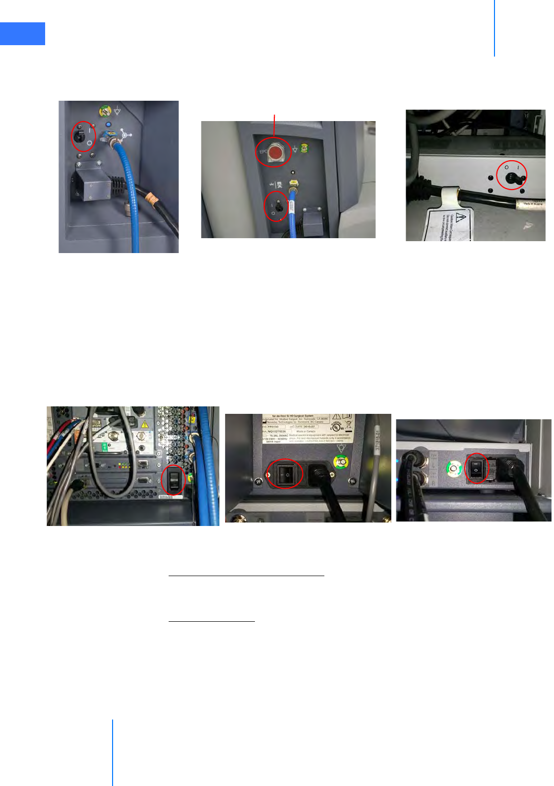
Startup
da Vinci® Si™
5-3
DRAFT/PRE-RELEASE/CONFIDENTIAL
10/9/14
2. Confirm that the mains circuit breaker switch on each of the Surgeon Console, Patient
Cart and Vision Cart is correctly set to the on position (indicated by “I” near each switch).
These switches are found on the rear of each component near the power cord inlet.
Figure 5.2 Circuit breaker switches on (“I”) for main components
• On the Patient Cart, make sure that the EPO button is not depressed, since it requires
a second press after use to reset it once it is used. See “Hard-Cycle” Power below.
3. On the Vision Cart, confirm that each of its component power switches—for the Core,
Camera Control Unit and Illuminator—is correctly set to the on position (indicated by “I”
on the switch). These components are not intended to be turned off or disconnected at
any time unless you are directed to do so by Intuitive Surgical Product Support. Also
confirm that each Vision Cart component power cord is plugged into the integrated
Vision Cart power strip.
Figure 5.3 Vision Cart component switches on (“I”)
Check Connection of System Cables
Check that the blue system cables are properly connected between the Core and the Surgeon
Console and Patient Cart. See section 4.2 System Cable Connections on page 4-3.
“Hard-Cycle” Power
If the entire system or one of the Patient Cart, Vision Cart or Surgeon Console fails to power on
normally by pressing one of the Power buttons, first check the AC power connections as
described above. If all AC power connections are complete, follow these steps to “hard-cycle”
power on the whole system:
Patient Cart Vision Cart (at base)
Surgeon Console
EPO button not depressed
Illuminator Camera Control Unit
Core

da Vinci® Si™
Startup 5-4
DRAFT/PRE-RELEASE/CONFIDENTIAL
10/9/14
1. Remove AC power from the Surgeon Console and Vision Cart by flipping each of their
mains circuit breaker switches to off (indicated by “O” near each switch). Leave them off
until the step in this sequence (below) that instructs you to switch them on again.
2. Because the Patient Cart will operate on battery even if you switch off its mains circuit
breaker, you must use the EPO (Emergency Power Off) button—the large red button on
the rear of the Patient Cart. The EPO button both disconnects the Patient Cart from AC
power and exits the default standby or sleep mode. Press the EPO button once to remove
all power; it will remain partially depressed. After at least 2 seconds, press the EPO button
again to reset it; it will rebound to its fully extended ready position, as it was before.
3. Switch on the mains circuit breaker switches on the Surgeon Console and Vision Cart.
(The Patient Cart circuit breaker should already be in the on position; make sure it is.)
After about 30 seconds, all three system components should be back in their default
standby power state, indicated by their Power buttons being lit amber.
4. Power on the system normally, by pressing the Power button on one of the Surgeon
Console, Vision Cart or Patient Cart.
• To address anomalous power behavior when trying to power a single system component
in stand-alone mode, “hard-cycle” power as described above for the applicable
component.
Restart from Automatic High Temperature Power Down
The entire da Vinci System is designed to undergo an automatic, controlled power-down
sequence in case a component or subsystem overheats while in normal operating mode (as
opposed to maintenance mode or stand-alone mode), thereby preventing system damage.
When the system detects overheating, it automatically initiates a 60-second power down
sequence and displays a message announcing it and showing the countdown. The power
down sequence cannot be interrupted. When it is complete, all three system Power buttons
will be lit amber, indicating the systems are in their default standby or sleep state.
• We recommend that you wait 5 minutes for the overheated portion of the system to cool,
and if possible, address situations that may be causing the system to overheat. For
example, make sure that all vented system covers are not blocked, and move systems
away from objects that may obstruct air flow in and out of system covers.
Follow the usual steps to restart the system from standby:
1. Press one of the system Power buttons. This powers on the system as normal; the Power
button LED flashes amber as normal during the power-up sequence, and lights solid blue
when power-up is complete.
• If overheating recurs, you can repeat the restart to recover, but we recommend that you
seek assistance from ISI Technical Support to address the cause of overheating.
“Cool Mode” Restart from Stand-Alone Mode
If overheating of a single component results in automatic power-down when it is operating in
stand-alone mode, it requires three Power button presses to recover that component to
normal operation. This is called “cool mode,” the mode in which the system component is
cooling from an overheated state. The button press behavior is as follows:
1. First Power button press has no noticeable effect.
2. Second Power button press returns the system component to standby state, as indicated
by its Power button lighting amber after several seconds.

Startup
da Vinci® Si™
5-5
DRAFT/PRE-RELEASE/CONFIDENTIAL
10/9/14
3. Third Power button press powers on the component normally.
• This restart behavior also applies if overheating occurs when a component or system is in
maintenance mode. Maintenance mode is reserved for use by Intuitive Surgical service
personnel, so users generally do not encounter this situation.
5.3 Startup Sequence
During the startup sequence, a system integrity test is performed. As part of this test, the
master controllers and all Patient Cart arms that are not stowed perform a self-test. The
masters move to their start position and must arrive there for the system to work. If a master is
impeded somehow, simply move it by hand to free it and it will move to its start position. The
instrument arms of the Patient Cart fully extend and perform a short mechanical integrity test,
if no cannula is installed and they are not in stow position (see 5.5 Stow Position on page 5-7).
If an arm bumps into something during the test, use the port clutch button to move the arm
clear of the obstacle. When clear, press and release the port clutch button to enable the test to
resume.
Once the system integrity test is successfully completed, the arm LEDs (of all arms not stowed)
will be lit white.
Note: During the startup sequence, do not put your head or other objects in the stereo
viewer. Do not activate any of the da Vinci Si System controls, including the clutch
buttons, footswitches, etc. While most button-presses will be ignored during the startup
sequence, some may cause a non-recoverable fault, which will mean that you will have
to restart the system. The Emergency Stop feature is available during startup if needed.
Once the system beeps, you may interact with the system controls.
Note: If the system detects a mounted sterile adapter, instrument, or cannula before
startup, the Patient Cart arms will not move during startup. This is a feature that is
designed to allow the system to stay safely connected to a patient during the startup
sequence.
Note: Instruments should be removed when starting the system, as long as this is
clinically acceptable.
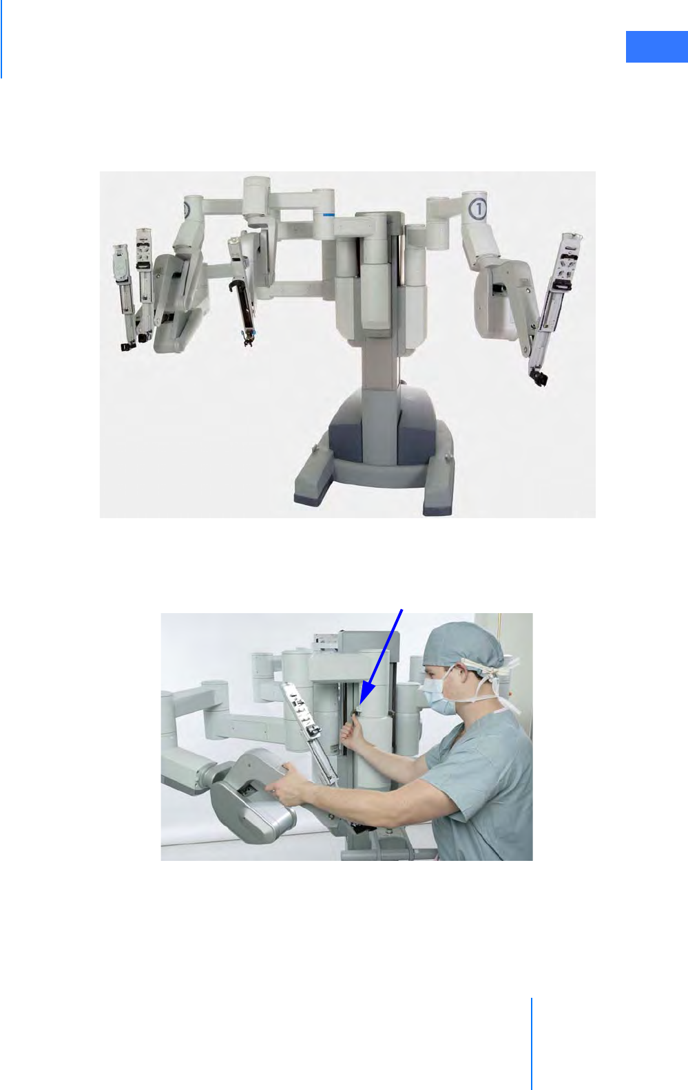
da Vinci® Si™
Startup 5-6
DRAFT/PRE-RELEASE/CONFIDENTIAL
10/9/14
5.4 Preparing the Patient Cart for Draping
Prepare the Patient Cart arms for draping by moving each arm's insertion axis to a vertical
position (90º). If draping instrument arm 3, ensure it is in front of the Patient Cart tower (Figure
5.4).
Figure 5.4 Instrument arms extended for draping
1. To move instrument arm 3 from one side of the Patient Cart to the other, release the latch
on the setup joint link (see Figure 5.5) closest to the Patient Cart tower.
Figure 5.5 Moving instrument arm 3
2. Then use the port clutch button to move the arm to the opposite side of the Patient Cart.
• Ensure the setup joint axis re-latches when the arm is moved completely to the other
side. To enhance flexibility for adjustments, the setup joint axis can be left unlatched.
If instrument arm 3 is not to be used during the procedure, leave the arm in stow
position (see Stow Position on page 5-7.)
Release latch
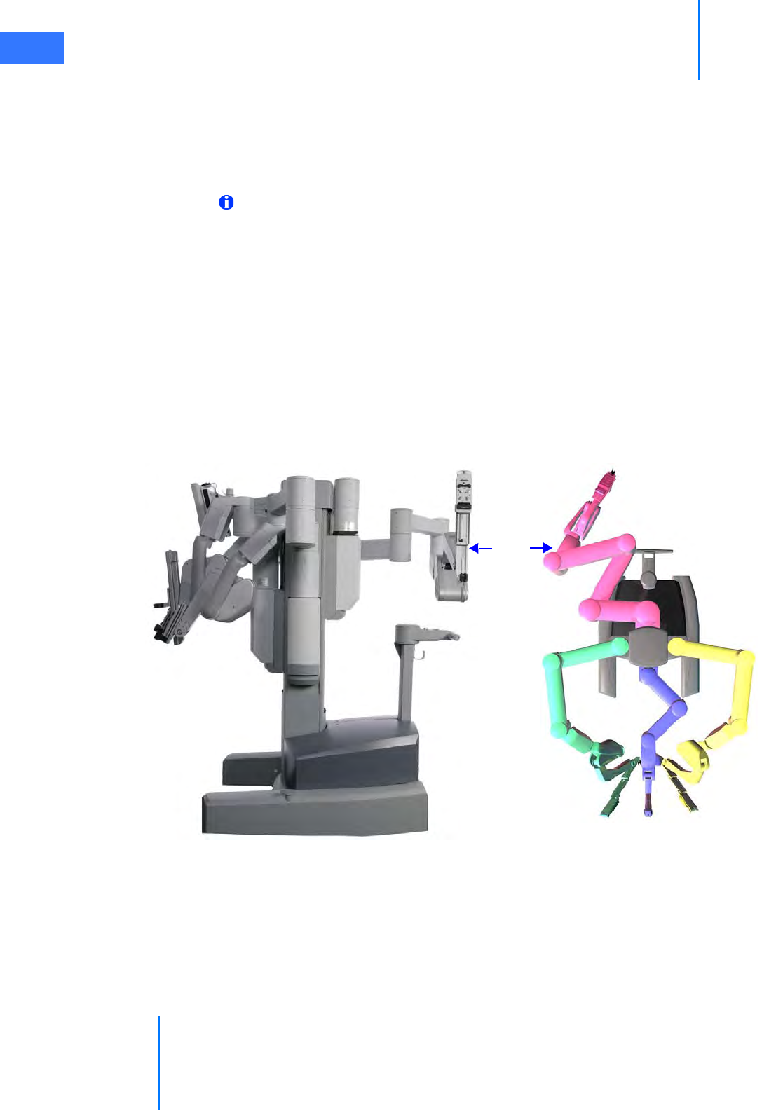
Startup
da Vinci® Si™
5-7
DRAFT/PRE-RELEASE/CONFIDENTIAL
10/9/14
5.5 Stow Position
The instrument arms are designed to be stowed, either for transport or when not in use. While
in stow position, the instrument arms will not move during the startup sequence. When an
instrument arm is in stow position, it cannot be activated and only clutching and fault state
LEDs function.
Note: Use extreme care when moving or positioning the Patient Cart to ensure the arms
do not hit any objects. If an arm hits an object while the Patient Cart is being moved or
positioned, contact Intuitive Surgical Technical Support to have the Patient Cart
inspected for damage.
To put instrument arm 1 or 2 in stow position:
1. Move the instrument arm close to the Patient Cart tower.
2. Once instrument arm 1 or 2 is close to the Patient Cart tower, the instrument arm
insertion axis may be collapsed entirely and pitched into the full back position.
To put instrument arm 3 in stow position:
1. Ensure the first setup joint link of instrument arm 3 is directed toward instrument arm 2
(to the right when looking from the rear).
2. Arrange the setup joint links as pictured in Figure 5.6.
Figure 5.6 Arranging instrument arm 3 for stow position
Arm 3
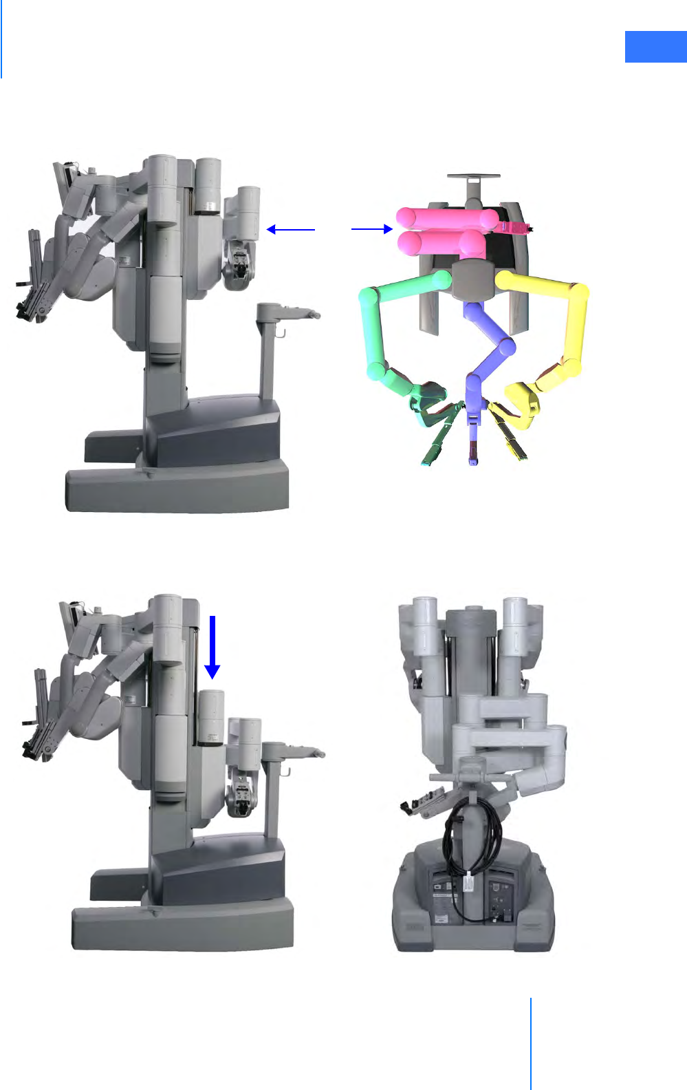
da Vinci® Si™
Startup 5-8
DRAFT/PRE-RELEASE/CONFIDENTIAL
10/9/14
3. Move the insertion axis to its fully collapsed and pitched back position, making sure the
instrument arm tucks under the bottom-most link (as shown in Figure 5.7). Move the
setup joint links as close to the Patient Cart tower as possible.
Figure 5.7 Instrument arm 3 in position to be stowed
4. Once instrument arm 3 is behind the Patient Cart tower (as shown in Figure 5.7), it can be
stowed. Move the entire setup joint to the bottom of its vertical range of motion.
Figure 5.8 Setup joint at bottom of vertical range of motion
Arm 3

Startup
da Vinci® Si™
5-9
DRAFT/PRE-RELEASE/CONFIDENTIAL
10/9/14
You can take Instrument arm 3 out of stow-position at any time using its port clutch button to
move the arm. As soon as you release the port clutch button in front of the Patient Cart tower,
the arm is enabled and the insertion axis extends in preparation for draping.
_________________________________End of section______________________________

da Vinci® Si™
Draping 6-1
DRAFT/PRE-RELEASE/CONFIDENTIAL
10/9/14
6Draping
Draping makes the Patient Cart arms sterile and suitable for surgery. This chapter will outline
how to drape the column, instrument arms, the camera arm, the camera head, and, optionally,
the touchscreen. It contains the following sections.
•6.1 Draping Guidelines, page 6-2
•6.2 Column Covering Procedure, page 6-2
•6.3 Instrument Arm Draping Procedure, page 6-6
•6.4 Camera Arm Draping Procedure, page 6-12
•6.5 Camera Head Draping Procedure, page 6-15
•6.6 Touchscreen Draping Procedure (Optional), page 6-16
Figure 6.1 Examples of draping
Drape Accessories Information
Drapes (see list below) are made by Microtek Medical and distributed by Intuitive Surgical.
Drapes
• Instrument Arm Drape, PN 420015
• Camera Arm Drape, PN 420279
• Camera Head Drape, PN 420273
• Monitor Drape, PN 420281
Microtek Medical, Inc.
512 Lehmberg Road
Columbus, MS 39704
www.microtekmed.com
Microtek Medical B.V.
Hekkenhorst 24
7207 BN Zutphen
THE NETHERLANDS
Distributed by:
Intuitive Surgical
1266 Kifer Road, Sunnyvale, California 94086 • USA
Intuitive Surgical Sàrl
1, chemin des Mûriers, 1170 Aubonne Switzerland
Customer Service from USA 1.800.876.1310
Customer Service from Europe +800.0821.2020
Manufactured in the U. S. A.
0044

Draping
da Vinci® Si™
6-2
DRAFT/PRE-RELEASE/CONFIDENTIAL
10/9/14
6.1 Draping Guidelines
• For speed, sterility and safety, draping should be done by a two-person team: a scrub
nurse or surgical assistant and a circulating nurse who can handle non-sterile
components.
• Drape the arms systematically, moving from left to right or right to left.
• First drape the column. You should then drape instrument arm 3 (if it will be used).
• Using the clutch buttons, the circulating nurse should move each straightened arm to
provide plenty of room to maneuver around the arm.
• Once an arm is draped, the scrub nurse should move the draped arm away from the
undraped arms and prepare to drape the next arm.
To drape the da Vinci Si, you need a three-quarter drape for the column, two or three
instrument arm drapes, a camera arm drape, and a camera head drape. Draping the
touchscreen is optional. Drapes are available for order as complete kits and as individual
items. Before beginning a procedure, make sure that you have sufficient draping supplies – at
least one backup of each required drape – to account for inadvertent contamination while
setting up the system, and have the endoscope laid out and ready for use.
WARNING: If the drape packaging is torn or open, do not use the drape, as the drape
may be unsterile.
Note: Never substitute generic drapes for Intuitive Surgical drapes. Drapes are available
from Intuitive Surgical or your distributor. Each piece of the custom draping has been
designed to maintain sterility and to make the draping process easy and efficient.
6.2 Column Covering Procedure
Intuitive Surgical recommends covering the Patient Cart column with a three-quarter drape for
procedures where fluid may splash onto the column. You should cover the column before
draping the instrument arms and camera arm.
• Minimum length and width for three-quarter drape: 75" x 50" (190.5 cm x 127 cm)
• Maximum length and width for three-quarter drape: 80" x 60" (203.2 cm x 152.4 cm)
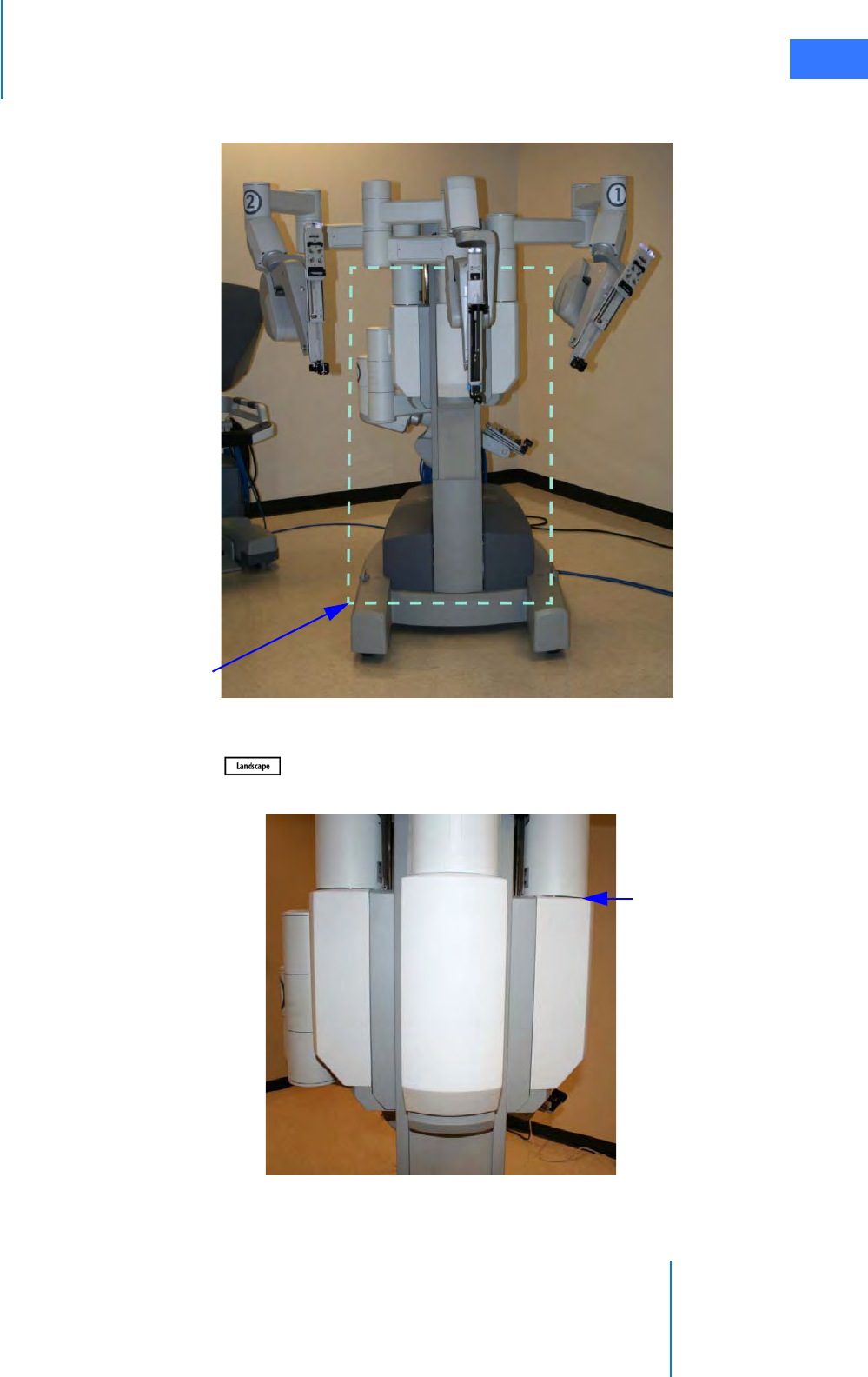
da Vinci® Si™
Draping 6-3
DRAFT/PRE-RELEASE/CONFIDENTIAL
10/9/14
1. Prepare the Patient Cart for draping by exposing the column as shown below.
Figure 6.2 Patient Cart prepared for draping
2. Wrap a three-quarter drape around the Patient Cart column. Use the drape in landscape
orientation ( ). Place the drape in the following areas:
• Over the setup joint ledge for instrument arms 1, 2, and the camera arm.
Figure 6.3 Setup joint ledge
Patient
Cart
column
Setup joint
ledge
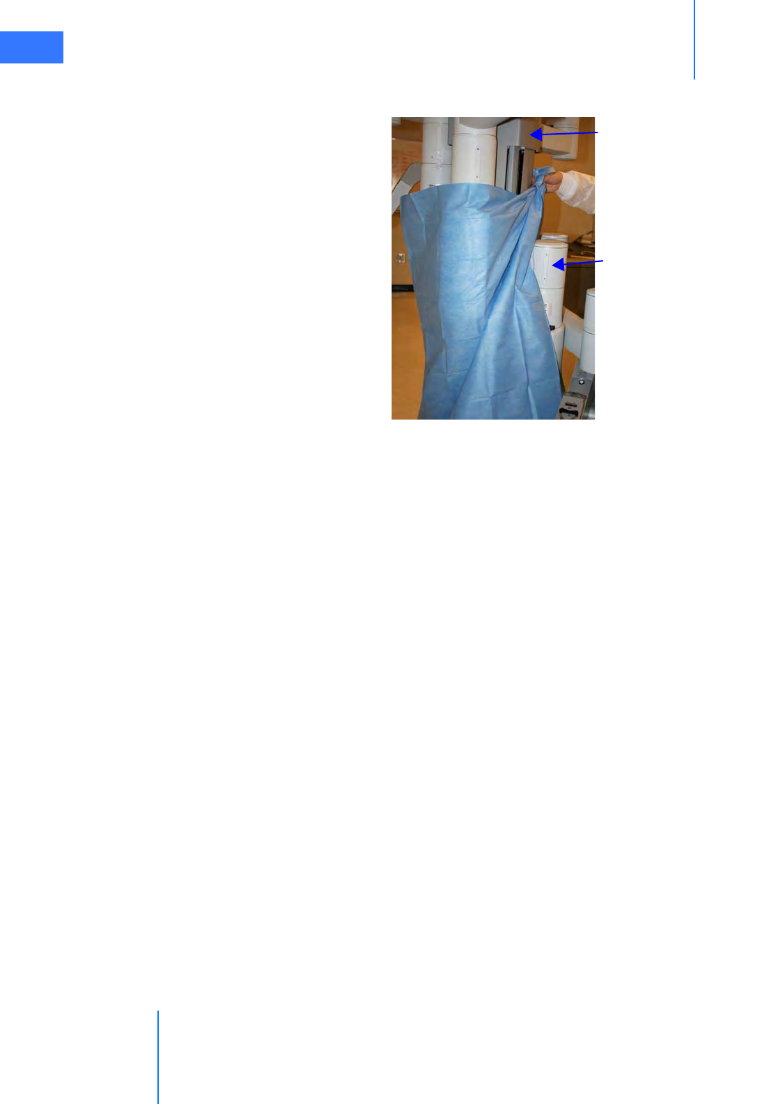
Draping
da Vinci® Si™
6-4
DRAFT/PRE-RELEASE/CONFIDENTIAL
10/9/14
• Between instrument arm 3 setup joint and the Patient Cart column. This configuration
allows for a mid-procedure third arm deployment if the arm is stowed.
Figure 6.4 Seen from rear right
Patient Cart
column
Instrument arm 3
(stowed)
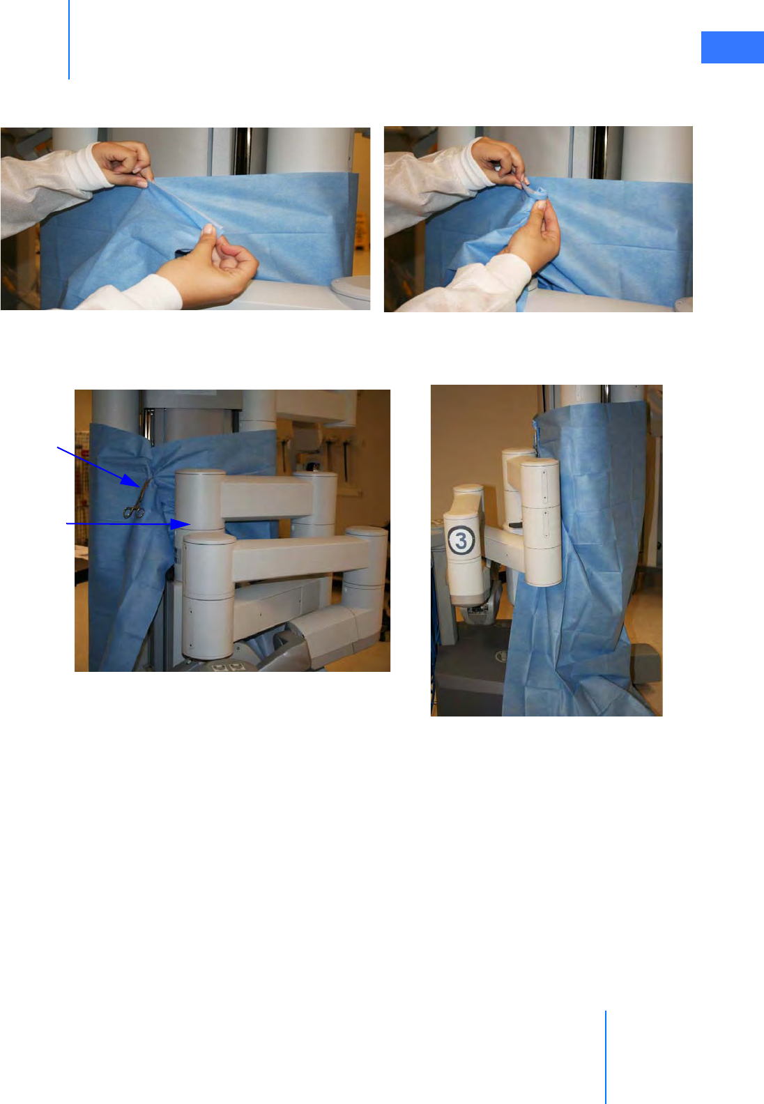
da Vinci® Si™
Draping 6-5
DRAFT/PRE-RELEASE/CONFIDENTIAL
10/9/14
3. Tighten and secure the drape behind the Patient Cart column.
• Roll the drape ends together to tighten
Figure 6.5 Rolling the drape ends together
• Secure with a towel clamp. Place the rolled drape (with towel clamp) on the opposite
side of the instrument arm 3 setup joint
Figure 6.6 Secure with towel clamp | Clamp opposite of instrument arm 3
Towel clamp
Instrument
arm 3
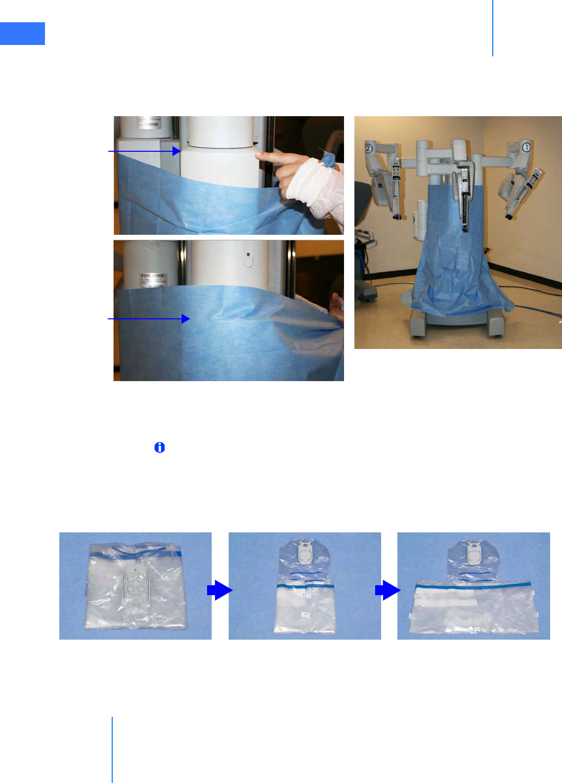
Draping
da Vinci® Si™
6-6
DRAFT/PRE-RELEASE/CONFIDENTIAL
10/9/14
4. After moving any instrument or camera arm setup joint up or down, you should readjust
the three-quarter drape. Always ensure the drape remains tight and secure above the
setup joint ledge for instrument arms 1, 2, and the camera arm.
5. Straighten out the drape so that it neatly covers the base of the cart.
Figure 6.7 Setup joint ledge | Completed Patient Cart with drape
6.3 Instrument Arm Draping Procedure
Note: The blue band on the drape indicates the sterility barrier. If a non-sterile person is
assisting in installation of the drape, he/she must not grasp the drape anywhere beyond
the blue band.
1. Circulating Nurse: Deliver the instrument arm drape to the scrub nurse in sterile fashion,
with the instrument arm sterile adapter facing the ceiling.
2. Scrub Nurse: Unfold the drape on a sterile table.
Figure 6.8 Unfolding instrument arm drape
Setup joint
ledge
Setup joint
ledge
(covered)
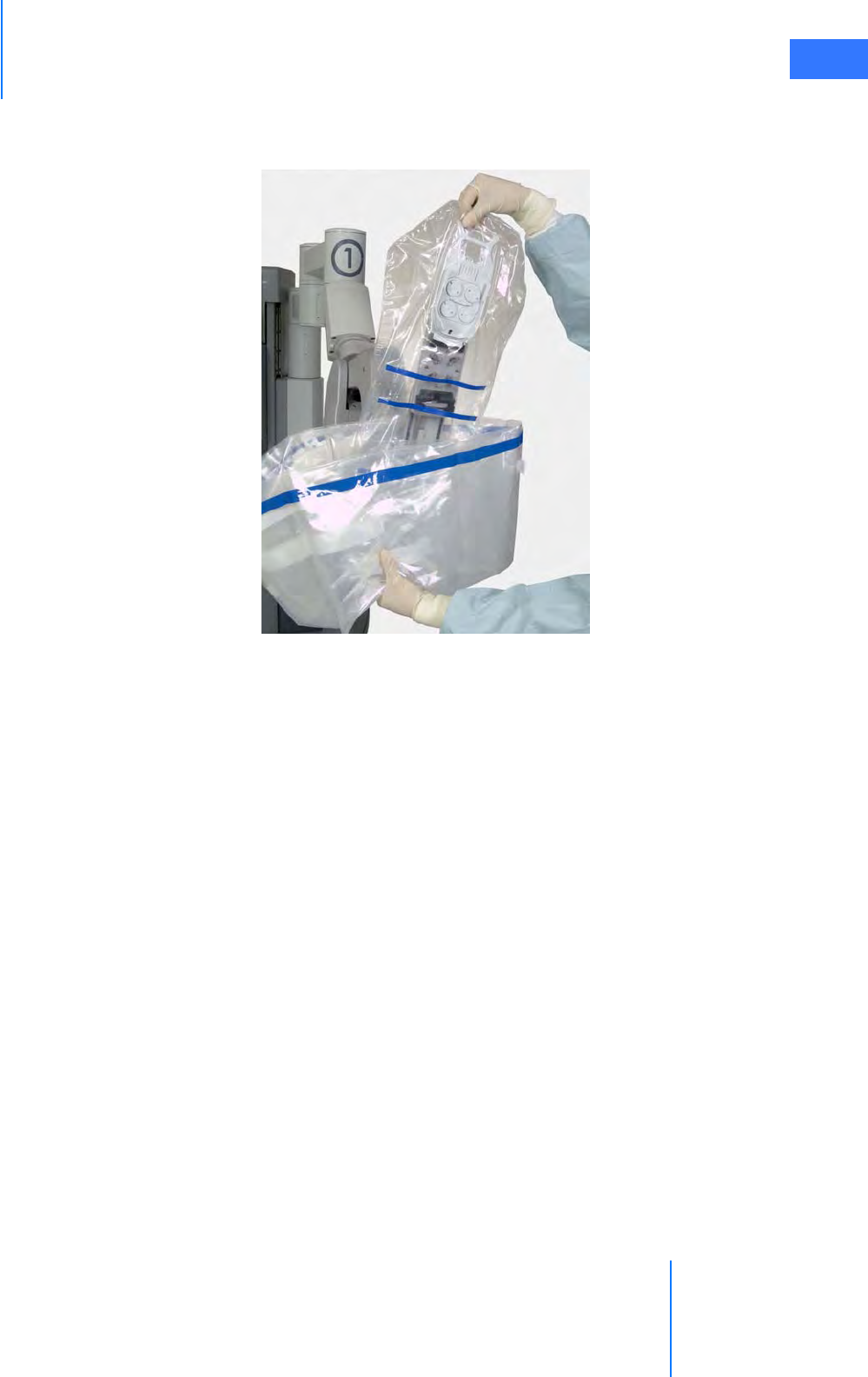
da Vinci® Si™
Draping 6-7
DRAFT/PRE-RELEASE/CONFIDENTIAL
10/9/14
3. Tent the opening of the drape and grip the outside with your finger and thumb. Hold the
top of the drape with the other hand. Lower the drape over the instrument arm insertion
axis.
Figure 6.9 Lowering the drape over the insertion axis
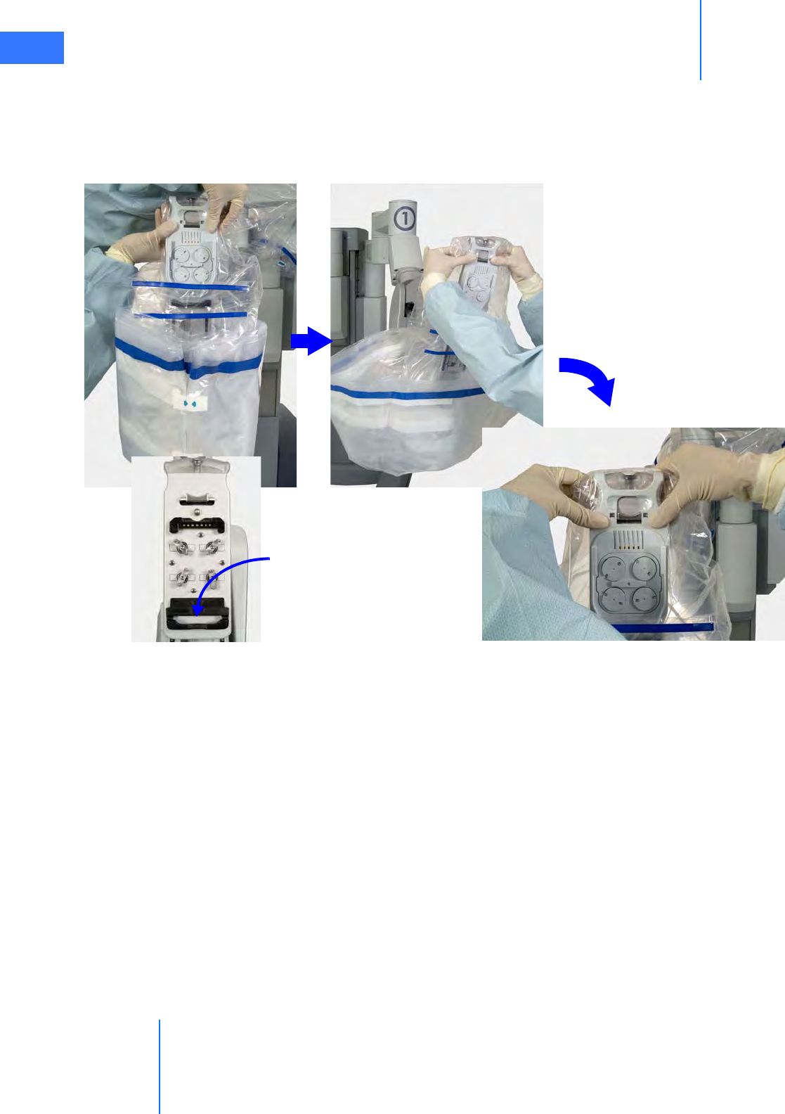
Draping
da Vinci® Si™
6-8
DRAFT/PRE-RELEASE/CONFIDENTIAL
10/9/14
4. Insert the base of the sterile adapter into the black molded piece into which it fits. Using
both thumbs, push the sterile adapter into the instrument arm until it clicks into place
(Figure 6.10). If sterile adapter does not engage, remove and re-seat the sterile adapter.
Confirm proper engagement using the steps under Sterile Adapter Engagement
Verification on page 6-11.
Figure 6.10 Insert base, press top to install sterile adapter
The wheels on the sterile adapter will spin, and you will hear three beeps, indicating that
the system recognizes the sterile adapter.
5. Remove the two tear-aways on the front of the drape.
Sterile adapter
base fits here
Press top to click
into place

da Vinci® Si™
Draping 6-9
DRAFT/PRE-RELEASE/CONFIDENTIAL
10/9/14
6. Using the cuff of the drape, move it back along the instrument arm toward the Patient
Cart tower (Figure 6.11).
Figure 6.11 Stretching the drape along the arm
7. Seat the cannula mount molding. Make sure the molding snaps over the cannula mount
(Figure 6.12).
Figure 6.12 Seat the cannula mount molding
Incorrect: Molding not over
mount tabs on right
Correct: Molding envelops
mount tabs on both sides
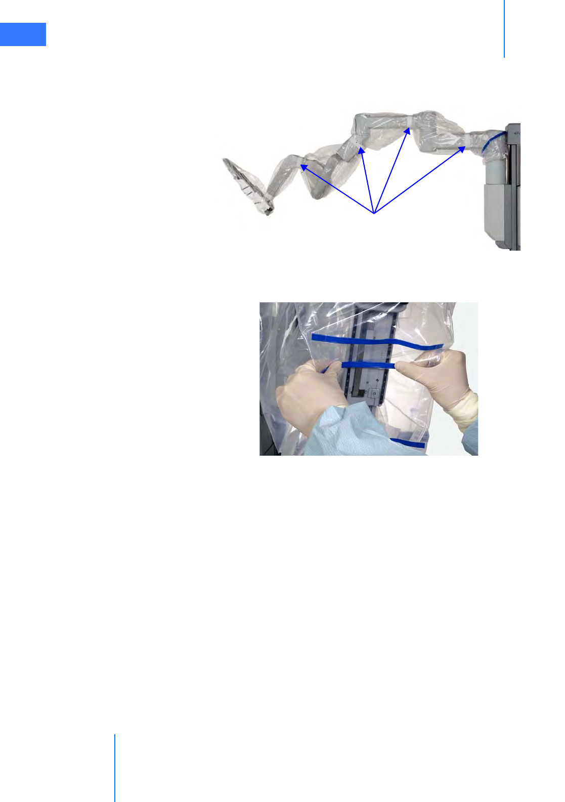
Draping
da Vinci® Si™
6-10
DRAFT/PRE-RELEASE/CONFIDENTIAL
10/9/14
8. Wrap all white drape straps snugly around the instrument arm, and attach each strap to
itself (Figure 6.13). You may wish to confirm that the arm moves without tearing the
drapes or straps.
Figure 6.13 Securing the drape with the drape straps
9. Bend the blue flex-strips to create a clear instrument insertion path along the axis of the
instrument arm.
Figure 6.14 Bend the blue flex-strips
Straps
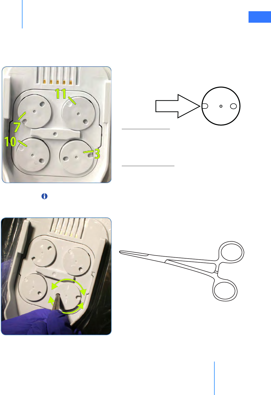
da Vinci® Si™
Draping 6-11
DRAFT/PRE-RELEASE/CONFIDENTIAL
10/9/14
Sterile Adapter Engagement Verification
It is important to ensure the sterile adapter built into the drape is properly engaged with the
instrument arm, so the instrument works properly when installed. Follow these steps and best
practices to ensure engagement.
Note: Once a sterile adapter is successfully engaged on the arm, it should not need to be
removed or reseated until the end of the procedure.
Open Notch
Open Notch Location:
Top Left disc – 7 o’clock
Top right disc – 11 o’clock
Bottom right disc – 3 o’clock
Bottom left disc – 10 o’clock
Clockwise from top left:
“7, 11, 3, 10”
The discs should be in this alignment after draping and
before installation of an instrument.
After the Sterile Adapter is attached and the discs
rotate back and forth, verify the position of the open
notch on each disc.
If any open notch does not match the position above,
use the closed tip of a sterile Kelly Forceps or
Hemostat instrument to manual rotate the disc.
Rotate the disc in either direction until it clicks into
place. The disc should no longer rotate once it is fully
engaged. If the sterile adapter does not engage properly,
remove and reseat the instrument arm drape.
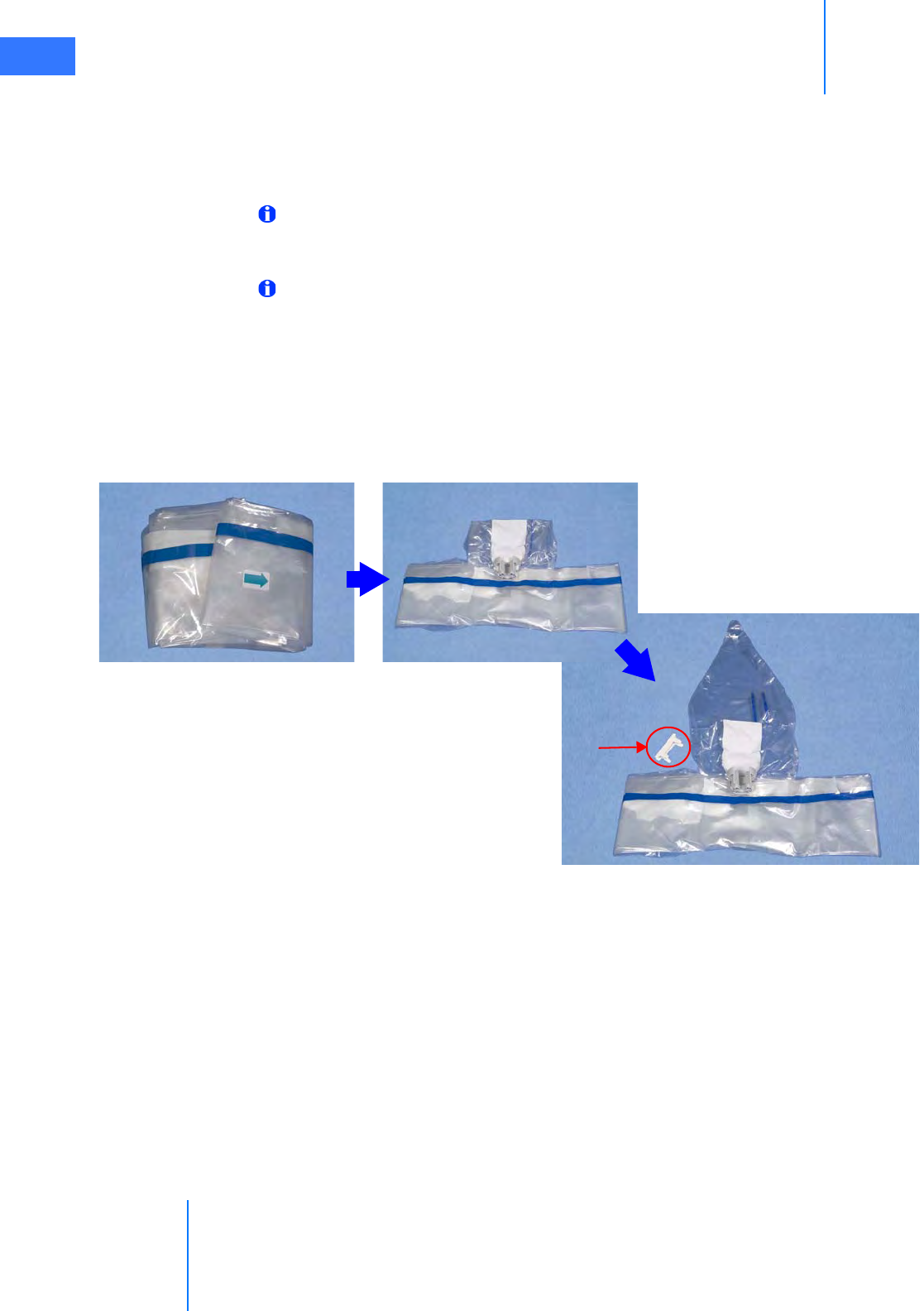
Draping
da Vinci® Si™
6-12
DRAFT/PRE-RELEASE/CONFIDENTIAL
10/9/14
6.4 Camera Arm Draping Procedure
Before you begin draping the camera arm, the sterile person should move the draped
instrument arms away from the camera arm, to provide plenty of room to walk between the
arms.
Note: Before draping the camera arm, make sure you install the correct endoscope
cannula mount based on which endoscope cannula will be used during the procedure.
Refer to the Instruments and Accessories User Manual for more information.
Note: The blue band on the drape indicates the sterility barrier. If a non-sterile person is
assisting in installation of the drape, he/she must not grasp the drape anywhere beyond
the blue band.
To begin draping the camera arm:
1. Circulating Nurse: Deliver the camera arm drape to the scrub nurse in sterile fashioning
the arrow-side facing up.
2. Scrub Nurse: Unfold the drape on a sterile table and remove the white retainer from the
sterile adapter.
Figure 6.15 Unfold camera arm drape and remove white retainer
Remove
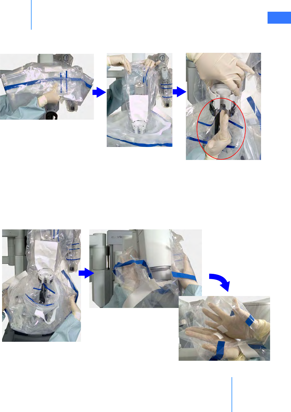
da Vinci® Si™
Draping 6-13
DRAFT/PRE-RELEASE/CONFIDENTIAL
10/9/14
3. Insert one hand into the bottom opening of the drape and hold the top of the drape with
the other hand. Lower the drape over the insertion axis and then lift the top of the drape
over the top of the arm’s insertion axis.
Figure 6.16 Lower over insertion axis, install sterile adapter
4. Now install the camera arm sterile adapter into the carriage on the camera arm. Using the
side of one hand as shown above, make a trough in the drape through the carriage to
create room for the endoscope to pass through. Then firmly push the camera arm sterile
adapter into place (Figure 6.16). To check if it is properly seated, pull up on the camera
arm sterile adapter, which should remain attached to the camera arm. Re-seat and
re-check as necessary.
5. Using the cuff of the drape, move the drape down along the camera arm setup joint to
the center column of the Patient Cart (Figure 6.17).
Figure 6.17 Extend drape to the center column and secure
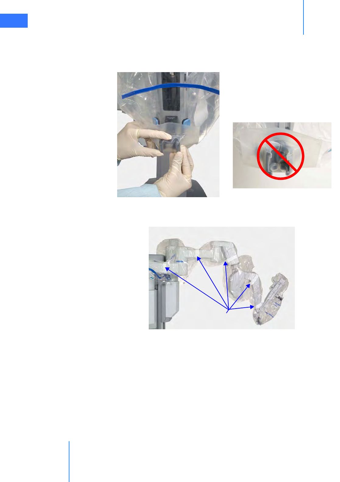
Draping
da Vinci® Si™
6-14
DRAFT/PRE-RELEASE/CONFIDENTIAL
10/9/14
6. Use your hands inside the drape cuff to engage the opposing Velcro strips near the center
column.
7. Seat the cannula mount molding. Make sure the molding snaps over the cannula mount
(see Figure 6.18 below and Figure 6.12 on page 6-9).
Figure 6.18 Seating the cannula mount molding
8. Wrap the white drape straps snugly all the way around the camera arm and tape each
strap’s end to itself.
Figure 6.19 Camera arm drape secured with straps
Straps
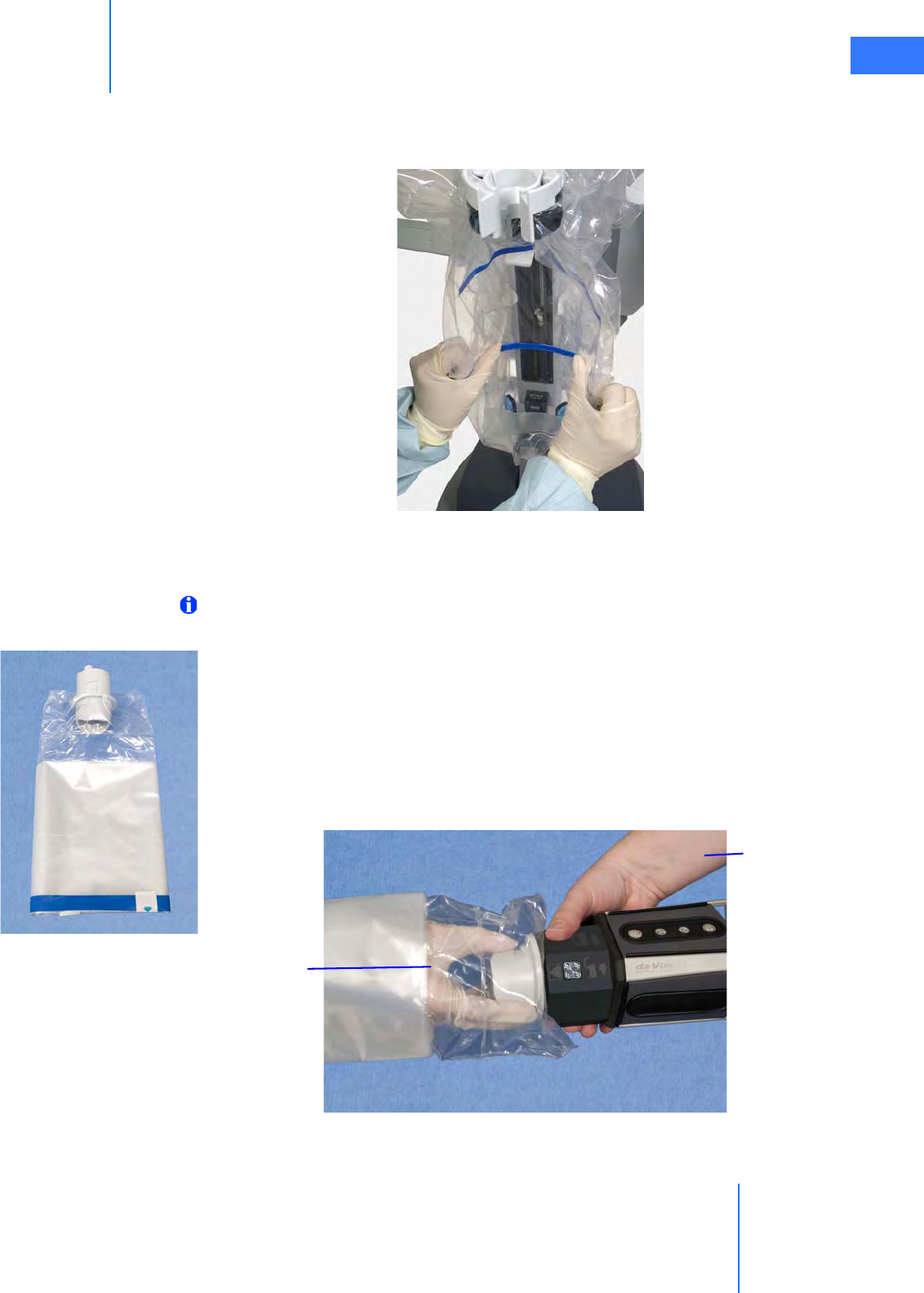
da Vinci® Si™
Draping 6-15
DRAFT/PRE-RELEASE/CONFIDENTIAL
10/9/14
9. Bend the blue flex-strips to create a clear path for the endoscope along the arm’s
insertion axis, and to ensure the camera arm drape does not stretch or tear during system
operation.
Figure 6.20 Bend the blue flex-strips around the insertion axis
6.5 Camera Head Draping Procedure
Note: Before draping the camera head, wipe the lenses to remove any debris or
smudges.
Since the Vision Cart and cables are not sterile, a non-sterile person (circulating nurse below)
must assist a sterile person (scrub nurse below) with draping and connecting the camera
head. (The camera head itself is not sterile and must not be autoclaved.)
To drape the camera head:
1. Circulating nurse: Deliver the camera drape to the scrub nurse in sterile fashion.
2. Scrub nurse: Unfold the drape. Then insert a hand into the open end of the drape, and
grab the camera head sterile adapter firmly.
Figure 6.21 Attaching camera head to sterile adapter
3. Circulating
Nurse
2. Scrub Nurse
(Sterile)
(Non-sterile)
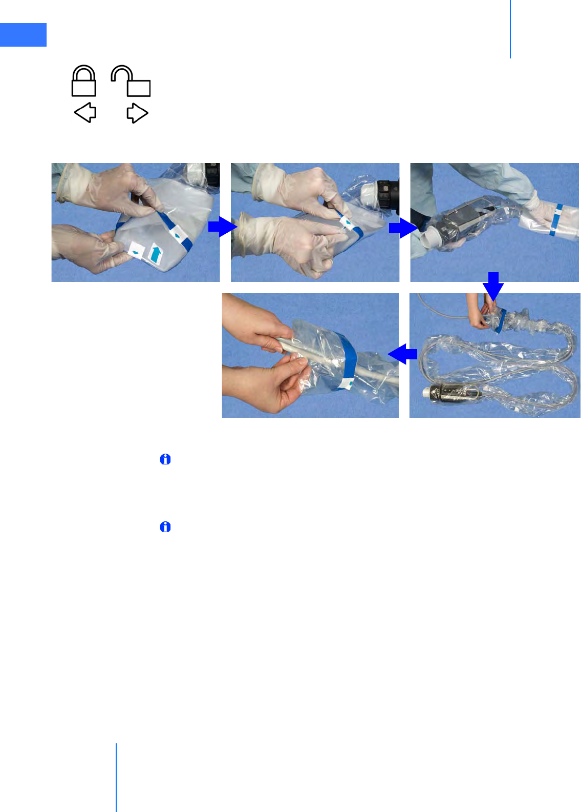
Draping
da Vinci® Si™
6-16
DRAFT/PRE-RELEASE/CONFIDENTIAL
10/9/14
3. Circulating nurse: Attach the camera head to the camera head sterile adapter. You must
align the pins in the camera head with the channels in the sterile adapter, push down and
turn until the camera head locks into place. You will hear a click once it locks into place.
Icons on the camera head ring-nut (shown at left) indicate the direction you must turn to
lock or unlock the sterile adapter in the camera head.
4. Scrub nurse: Invert the drape over the camera head.
Figure 6.22 Invert drape over camera head, pull along cables
5. Circulating nurse: Pull the drape along the cables.
Note: To avoid contamination, arrange the draped assembly and cables on the table in
an “S” shape, or coil into a sterile basin.
6.6 Touchscreen Draping Procedure (Optional)
Note: The blue band on the drape indicates the sterility barrier. If a non-sterile person is
assisting in installation of the drape, he/she must not grasp the drape anywhere beyond
the blue band. Due to the size of the touchscreen drape, a second sterile person may be
needed to assist with touchscreen draping. To begin draping the touchscreen monitor:
1. Circulating Nurse: Remove the monitor drape from the sterile packaging.
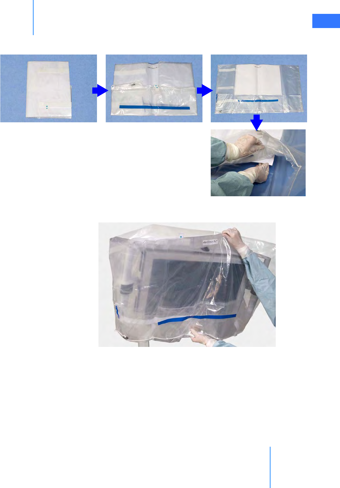
da Vinci® Si™
Draping 6-17
DRAFT/PRE-RELEASE/CONFIDENTIAL
10/9/14
2. Scrub Nurse: Place the drape on a sterile table with the label facing up. Remove and
discard the paper insert.
3. Place one hand in the bottom opening of the drape and hold the top of the drape with
the other hand. Lower the drape over the monitor with the label facing towards you.
Figure 6.24 Lower the drape over the monitor
Figure 6.23 Unfold monitor drape and remove paper
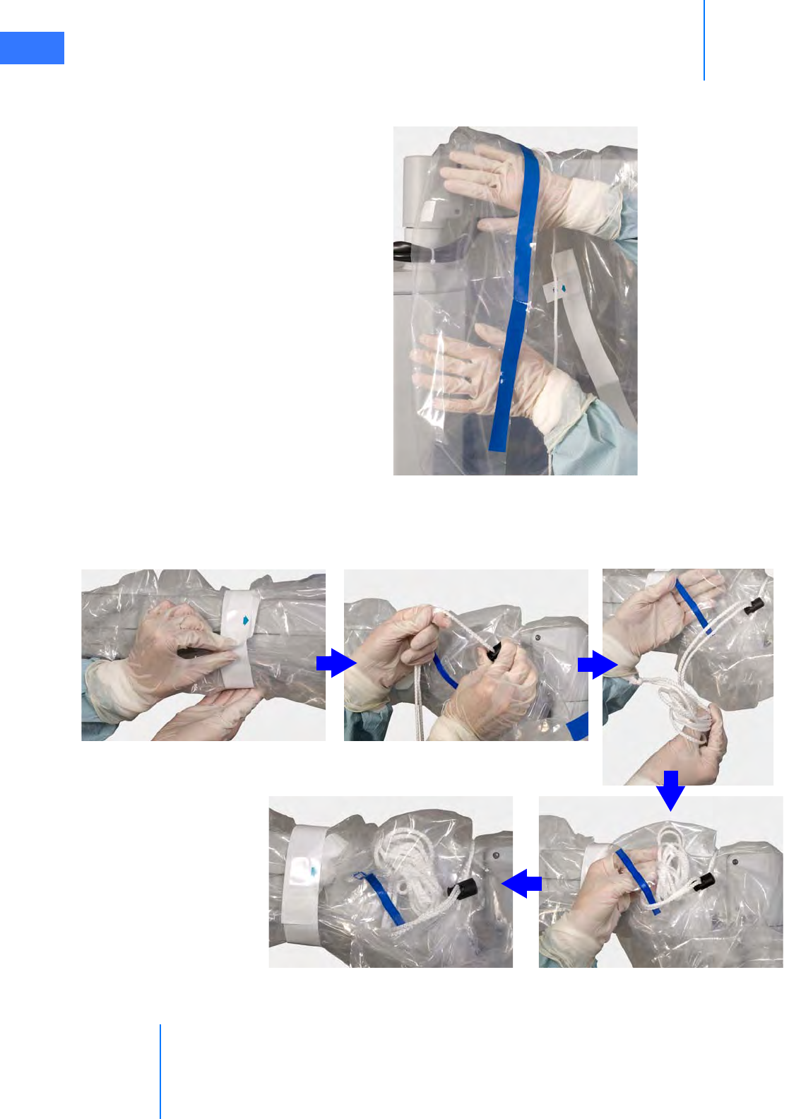
Draping
da Vinci® Si™
6-18
DRAFT/PRE-RELEASE/CONFIDENTIAL
10/9/14
4. Use the cuff of the drape to move the drape all the way down to the base of the monitor
arm.
Figure 6.25 Push drape back with cuff
5. Secure the tape around the arm and then tighten the drawstring around the base of the
monitor arm, using the fastener to keep it secure (Figure 6.26). Tuck any extra drawstring
inside the pouch located near the cuff of the drape (Figure 6.26).
Figure 6.26 Secure tape, tighten drawstring, tuck extra inside
Pull
Open
Tuck
Done
Tape
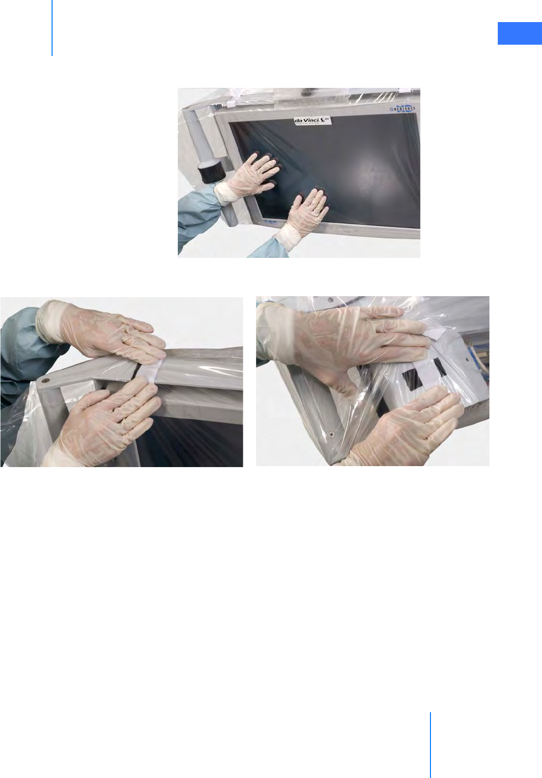
da Vinci® Si™
Draping 6-19
DRAFT/PRE-RELEASE/CONFIDENTIAL
10/9/14
6. Align the drape window to the monitor. Press the drape so that it clings smoothly to the
monitor surface.
Figure 6.27 Smoothing the drape on the monitor
7. Secure the Velcro straps on the sides and rear of the monitor.
Figure 6.28 Secure Velcro straps on sides and rear
When you finish draping, tuck the arms against the column and stow the Patient Cart for
surgery.
When draping is complete, the Vision System is ready for setup, which is covered in the next
chapter.
_________________________________End of section______________________________
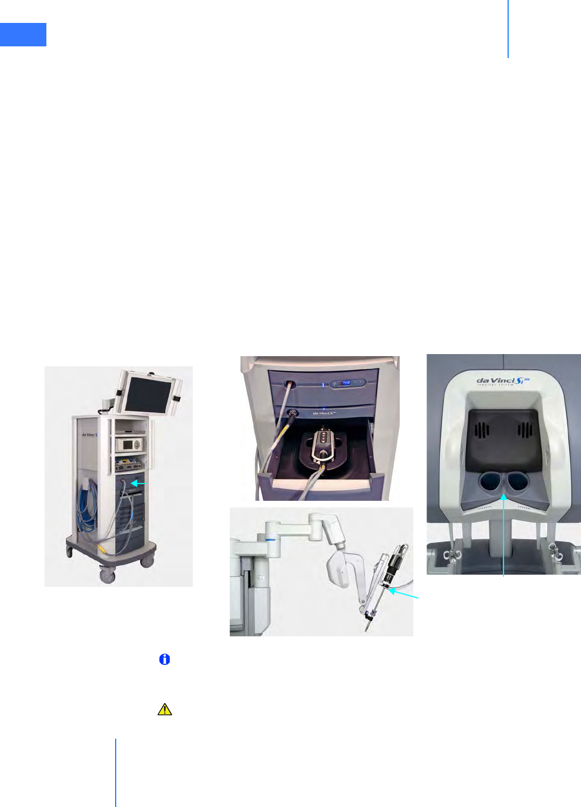
Vision System Use
da Vinci® Si™
7-1
DRAFT/PRE-RELEASE/CONFIDENTIAL
10/9/14
7Vision System Use
This chapter explains the setup and use of the da Vinci® Si ™ HD Vision System. The following
subjects are covered:
•7.1 Vision System Overview, page 7-1
•7.2 Setting Up the Vision System, page 7-5
•7.3 Working with the Illuminator Controls, page 7-14
•7.4 Working with the Touchscreen Vision Controls, page 7-15
•7.5 Adjusting the Touchscreen Monitor, page 7-20
•7.6 Troubleshooting Image Quality, page 7-20
7.1 Vision System Overview
The 3DHD Vision System provides a high resolution image for the surgeon (at the 3D viewer)
and the patient-side assistant (at the touchscreen). The 3DHD endoscope assembly
(endoscope and camera head) can be used manually (that is, handheld, as with a traditional
endoscopy cart) or can be mounted on the camera arm to assist with preoperative exploration.
Figure 7.1 Vision system components
Note: The da Vinci Si System must be used only with ISI approved or supplied cameras,
endoscopes, accessories and image processing equipment. This ensures optimal image
quality and da Vinci Si System performance.
CAUTION: Surgery should be performed with the da Vinci Si System only when the vision
system provides sufficient visualization to safely perform surgical tasks.
Surgeon Console
Stereo viewer
Illuminator with
cables attached
while stowed
Endoscope assembly
installed on camera arm
Vision Cart
(no drape)
Connected camera head in storage drawer
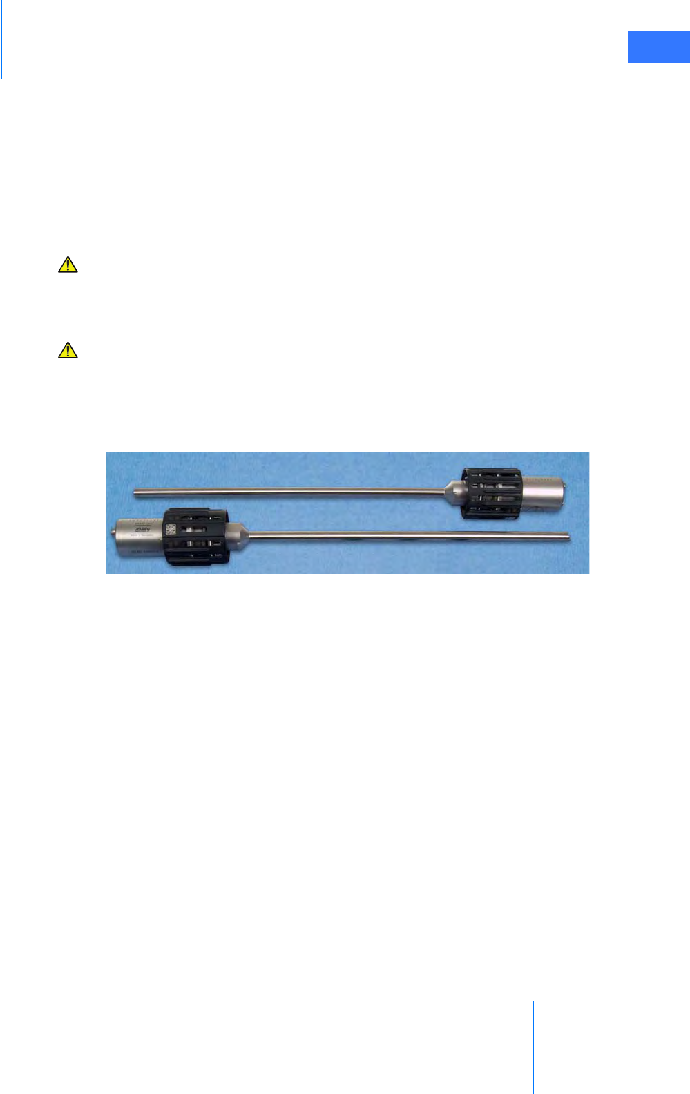
da Vinci® Si™
Vision System Use 7-2
DRAFT/PRE-RELEASE/CONFIDENTIAL
10/9/14
Illuminator
The Illuminator provides lighting for the surgical field. The Illuminator monitors the life left on
the lamp module and notifies you when replacement is recommended. For replacement
instructions, see Illuminator Lamp Module Replacement on page 12-2. For additional, general
information and specifications regarding the Illuminator, see Appendix C: Illuminator
Information.
Endoscopes
CAUTION: Do not autoclave the endoscope. The endoscope should be cleaned and
sterilized before each procedure and does not require sterile draping during surgical
use. Clean and sterilize the endoscope prior to each use. Refer to Reprocessing
Instructions User Manual (PN 550875) for reprocessing methods and parameters.
CAUTION: Handle endoscope with care. Dropping the endoscope may result in damage
and loss of functionality. Inspect endoscope for damage prior to use.
The endoscope provides a left and right optical channel to capture the surgical image. Light
from the Illuminator is projected on the surgical field through integrated fiber optic channels.
Heat from the fiber optic channels helps to minimize fogging at the endoscope lens.
Figure 7.2 Examples of endoscopes
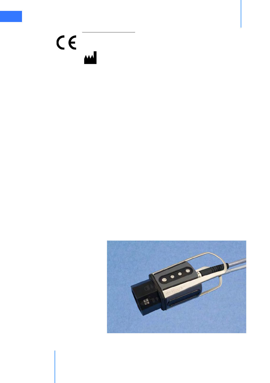
Vision System Use
da Vinci® Si™
7-3
DRAFT/PRE-RELEASE/CONFIDENTIAL
10/9/14
Endoscope Information
Intuitive Surgical endoscopes (see list below) are made by Schoelly Fiberoptic and distributed
by Intuitive Surgical.
Endoscopes
• 8.5 mm Endoscope (0° tip), PN 371938
• 8.5 mm Endoscope (30° tip), PN 371939
• 8.5 mm Fluorescence Endoscope (0° tip), PN 372010
• 8.5 mm Fluorescence Endoscope (30° tip), PN 372011
• 12 mm Endoscope (0° tip), PN 370890
• 12 mm Endoscope (30° tip), PN 370891
• 12 mm Fluorescence Endoscope (0° tip), PN 370892
• 12 mm Fluorescence Endoscope (30° tip), PN 370893
Camera Head
The 3D camera head contains two HD video cameras. One camera is used for the right optical
path and one for the left optical path. The high definition vision system provides both a
widescreen (16:9) and a magnified view through the use of digital zoom.
Figure 7.3 Camera head
Schoelly Fiberoptic GmbH
Robert-Koch-Str. 1-3
79211 Denzlingen
GERMANY
Distributed by:
Intuitive Surgical
1266 Kifer Road, Sunnyvale, California 94086 • USA
Intuitive Surgical Sàrl
1, chemin des Mûriers, 1170 Aubonne Switzerland
Customer Service from USA 1.800.876.1310
Customer Service from Europe +800.0821.2020
Manufactured in Germany.
0297
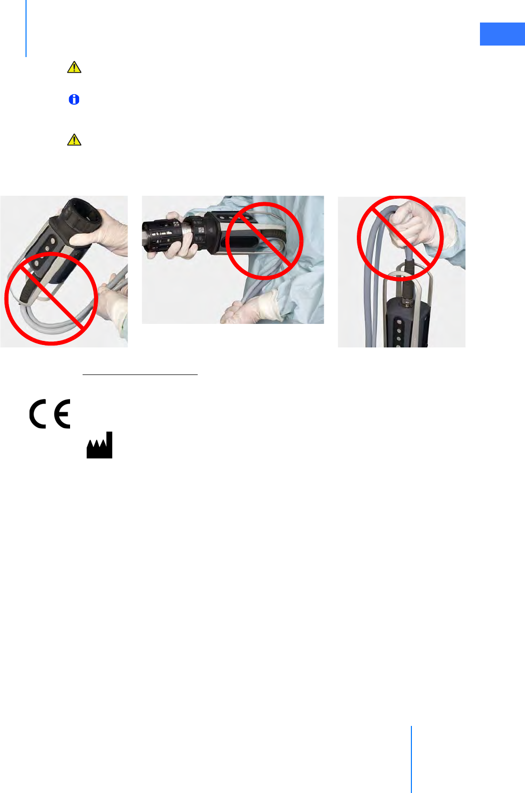
da Vinci® Si™
Vision System Use 7-4
DRAFT/PRE-RELEASE/CONFIDENTIAL
10/9/14
CAUTION: Handle the camera head carefully. Dropping the camera head may result in
damage and loss of camera functionality.
Note: Damage to the camera cable can occur through repetitive actions during use in
surgical procedures. These failures usually occur near the camera head.
CAUTION: Handle the light guide cable carefully. If the cable is bent sharply or kinked, it
can damage the fiber optic material enclosed in the light guide cable. Such damage can
substantially reduce the amount of light transmitted through the light guide cable
(Figure 7.4).
Figure 7.4 Examples of mishandling camera head cables
Camera Head Information
Intuitive Surgical camera heads [Camera Head Assembly, PN 655859 (371952) and Camera
Head Assembly, PN 655858 (372126)] are made by Schoelly Fiberoptic and distributed by
Intuitive Surgical.
Touchscreen Monitor
The touchscreen enables you to view and telestrate on the surgical field (and/or optional
video inputs), and to adjust vision and system settings. A microphone and speaker on the
touchscreen facilitate communication between the surgeon and the patient-side assistant.
Schoelly Fiberoptic GmbH
Robert-Koch-Str. 1-3
79211 Denzlingen
GERMANY
Distributed by:
Intuitive Surgical
1266 Kifer Road, Sunnyvale, California 94086 • USA
Intuitive Surgical Sàrl
1, chemin des Mûriers, 1170 Aubonne Switzerland
Customer Service from USA 1.800.876.1310
Customer Service from Europe +800.0821.2020
Manufactured in Germany.

Vision System Use
da Vinci® Si™
7-5
DRAFT/PRE-RELEASE/CONFIDENTIAL
10/9/14
7.2 Setting Up the Vision System
This section explains how to prepare the vision system for use.
CAUTION: Failure to adhere to approved operating practices may result in damage to
the endoscope. Examples of improper practices include: dropping of equipment,
collisions, and improper cleaning and sterilization techniques. A damaged endoscope
may result in fragments falling into the patient.
Pre-operative Inspection
The endoscope and corresponding endoscopic equipment and accessories should be
thoroughly inspected for any mechanical or optical defects before each procedure. The glass
surfaces in the light ports at the distal tip and those located at the camera end should be clean
and free of any deposits and residues to ensure a bright and clear image. Inspect surfaces
carefully for any irregularities or damage, such as sharp edges, cracks, dents, mechanical
and/or thermal defects due to inadequate application of electrosurgery or other instruments.
Careful inspection and assembly as described in this section can prevent loss of any
components during use.
WARNING: Do not use endoscopes with any defects or signs of damage, including
damage to the light ports or fiber surfaces, as serious injury or surgical complications
may occur to the patient.
WARNING: Do not look into the light at the tip of a fiber-optic bundle when the lamp is
on. As with any bright light, permanent eye injury can result.
Inspecting Glass and Endoscope Surfaces
Follow these steps to inspect endoscope light ports and fiber surfaces:
1. Hold the distal endoscope tip toward a bright ceiling lamp.
2. Inspect the light ports. The individual fibers should appear bright.
3. Move the distal endoscope tip held toward the lamp slightly to observe a noticeable
change in brightness of the fibers within the light port surface. Some fibers will remain
dark without any impact on quality, but if the majority of the fibers appear dark then the
resulting limited illumination may restrict adequate operation.