Intuitive Surgical CHB01 RFID TRANSCEIVER 3D-HD CAMERA HEAD User Manual da Vinci Si
Intuitive Surgical, Inc. RFID TRANSCEIVER 3D-HD CAMERA HEAD da Vinci Si
Contents
- 1. User Manual Part 1
- 2. User Manual Part 2
- 3. User Manual Part 3
- 4. User Manual Part 4
User Manual Part 3
da Vinci® Si™
Appendix A: Error Handling A-3
DRAFT/PRE-RELEASE/CONFIDENTIAL
10/9/14
After Disabling an Instrument Arm
After you disable an instrument arm, you still can use the arm clutch and port clutch buttons
to move the arm out of the way.
Disabling the Instrument Control Box (ICB)
In the event of an error specific to the ICB, the system presents the option to disable the ICB on
the touchscreen and touchpad. Once the ICB has been disabled, it can not be re-enabled until
the next power cycle. Intuitive Surgical designed this feature to allow a user to complete a
procedure without use of the EndoWrist instruments that employ the ICB, such as the Vessel
Sealer.
Non-Recoverable Faults
If a fault is non-recoverable, the system must be restarted. The following message is displayed:
Non-recoverable fault: XXXX
Restart System to continue.
Restarting the System During a Procedure
If a non-recoverable fault occurs during a procedure, you must completely remove all
instruments from the system. The endoscope does not need to be removed. Follow these
steps to restart the system:
1. Completely remove all instruments from the system. The endoscope does not need to be
removed. If an instrument is grasping tissue, follow the grip release instructions in
Chapter 9, Grip Release, on page 9-13.
WARNING: If it is not clinically possible to remove an instrument, closely monitor the
instrument arm during restart to ensure that no motion occurs.
2. Power off the system: Press the Power button on any system component.
The system takes several seconds to shut down. When complete, all system Power but-
tons will be lit amber, indicating standby mode, and readiness for restart.
3. Restart the system: Press the Power button on any system component.
4. After the system has restarted successfully, then the instruments can be reinserted.
Note: During system restart, video is temporarily unavailable at the Surgeon Console
viewer and touchscreen monitor.
Note: If the fault cannot be cleared by a system restart, call Intuitive Surgical Technical
Support.
Emergency Stop
Press the red Emergency Stop button should it be necessary to stop system operation at any
time. The Emergency Stop button will cease robotic control of the instruments and
endoscope. The instruments and endoscope will stay in their last commanded position.
If the instrument grips are closed when the Emergency Stop button is pressed, the grips will
remain closed. However, the gripping force of the instrument may decrease.
Pressing Emergency Stop initiates a recoverable fault, which you can override by pressing
Recover on the touchscreen or touchpad. The Emergency Stop button illuminates when
pressed and remains illuminated until the fault is recovered.

Appendix A: Error Handling
da Vinci® Si™
A-4
DRAFT/PRE-RELEASE/CONFIDENTIAL
10/9/14
EPO (Emergency Power Off)
Figure A.3 EPO button on rear of Patient Cart
The Emergency Power Off (EPO) button is on the back of the Patient Cart. Press this button to
completely remove power to the Patient Cart. The system classifies this a non-recoverable
fault. The system must be restarted.
Battery Backup
Should the Patient Cart be unplugged, the system will generate a recoverable fault that must
be addressed to continue a procedure. System operation will be allowed to continue on
reserve power, but with basic functionality only.
Note: Battery backup is only intended for safe removal of the system components from
the patient and is not intended for continuing the procedure.
Battery Low Condition
If there is insufficient battery backup power on the Patient Cart, cart drive is disabled and the
user will have to wait for the battery backup to charge.
• To move the cart manually, move the shift switches on the base of the cart to the neutral
position. When finished moving the cart, be sure to move the shift switches back to the
drive position.
Note: The backup battery is not user-serviceable, and must be replaced by authorized
personnel only. Contact Intuitive Surgical Technical Support for details.
Note: The Patient Cart battery should be adequately charged. If not, an error message
appears on the monitors. You can override the error if the Patient Cart is plugged into AC
power.

da Vinci® Si™
Appendix A: Error Handling A-5
DRAFT/PRE-RELEASE/CONFIDENTIAL
10/9/14
A.3 Conversion to Open Surgery
If a situation arises where a conversion to open surgery is required, perform the following
steps to remove the system from the patient:
1. Remove the instruments and endoscope from the patient. Note the following:
Note: Whenever possible, use Surgeon Console control to release the instrument grips.
a. In case of system failure while the instrument is grasping tissue, the grips can be
manually opened by following the grip release instructions, see Grip Release on page
9-13 (Chapter 9, Patient Cart Use).
WARNING: Do not perform grip release on a non-faulted system without first pressing
the Emergency Stop button. Failure to observe this warning may result in unintended
instrument motion or damage to the grip release mechanism.
WARNING: Rotating the grip release tool too far and/or in the incorrect direction can
cause unintended instrument motion or damage to the grip release mechanism.
2. Disconnect the cannulae from the instrument and camera arms.
3. Move the instrument and camera arms away from the patient.
Note: If the system is in a fault state while converting to open surgery, the Patient Cart
will still allow use of the port clutch buttons. If the system loses all power, the arms and
setup joints may be overpowered to move the arms as necessary.
_________________________________End of section______________________________
Appendix B: da Vinci Si-e Surgical System
da Vinci® Si™
B-1
DRAFT/PRE-RELEASE/CONFIDENTIAL
10/9/14
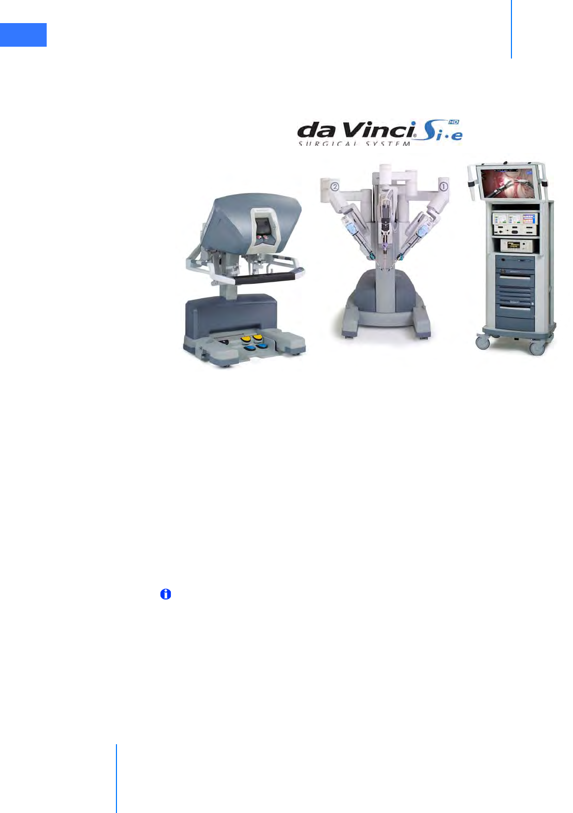
BAppendix B: da Vinci Si-e Surgical System
This appendix provides detailed information and specifications for the da Vinci Si-e Surgical
System, an upgradable configuration of the da Vinci Si System, visibly distinguished by a 3-arm
Patient Cart. The da Vinci Si-e System is designed to be upgradable anytime to a full-featured
da Vinci Si System (single or dual console) – by Intuitive Surgical technicians. This section
describes the characteristics that distinguish it from the da Vinci Si System.
B.1 System Component Compatibility
The da Vinci Si-e System uses the same Surgeon Console, which is interchangeable with any
da Vinci Si System. In contrast, the 3-arm Patient Cart and the Vision Cart of the da Vinci Si-e
System are not interchangeable with the 4-arm Patient Cart and Vision Cart of a da Vinci Si
System; the specific da Vinci Si-e System components must be used together for the
da Vinci Si-e System to work. The system software recognizes when you connect an
incompatible combination of Patient Cart and Vision Cart, notifies you on screen and prevents
use of the disallowed combination.
Note: The da Vinci Si-e System does not support dual console surgery.
da Vinci® Si™
Appendix B: da Vinci Si-e Surgical System B-2
DRAFT/PRE-RELEASE/CONFIDENTIAL
10/9/14
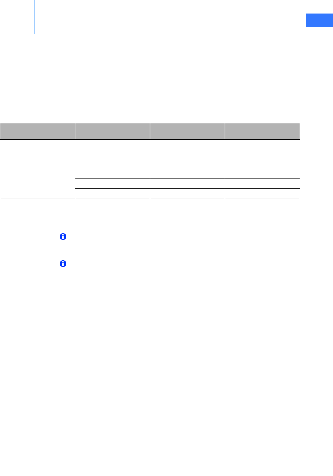
Use of Third-Party Monitors
The da Vinci Si-e System supports use of external monitors in high definition or standard
definition, by means of the standard video out connectors on the back of the Core, the
Surgeon Console, and the Camera Control Unit (CCU). The table below describes the available
video output options on the back of the Core. These are not user-configurable: you cannot
select the video output format of the Video Out bay Aux connectors (back of the Core). The
da Vinci Si-e System selects the appropriate output format based on the device connected to
the Aux connector. See section 4.5 Video and Audio Connections and section H.5 Video Patch
Panels for more details.
Table B-1 Si-e Video Connections
The Video Out bay Aux supports only one video format at a time.
Note: Video outputs make available only the surgeon’s view overlays. No external
monitor used with the da Vinci Si-e System can support the touchscreen overlays nor
functionality of the da Vinci Si System.
Note: If the system has OnSite installed, the OnSite status icons will be present on the
Vision Cart monitor even though the touchscreen function is not available. All other
OnSite features are supported on the Si-e System.
Component Connector Output
Format Resolution Overlay
Video Out bay Aux, back of
Core
DVI (analog and digital) XGA, SXGA, WXGA+ or
720p, automatically
configured
Surgeon’s view
Composite (analog) NTSC or PALaSurgeon’s view
S-Video (analog) NTSC or PALaSurgeon’s view
SD-SDI (digital) NTSC or PALaSurgeon’s view
a. NTSC or PAL is standard definition and is determined by country.
Appendix B: da Vinci Si-e Surgical System
da Vinci® Si™
B-3
DRAFT/PRE-RELEASE/CONFIDENTIAL
10/9/14
B.2 da Vinci Si-e Differences
Users of the da Vinci Si-e System should note the following differences in features and
behavior compared to the da Vinci Si System.
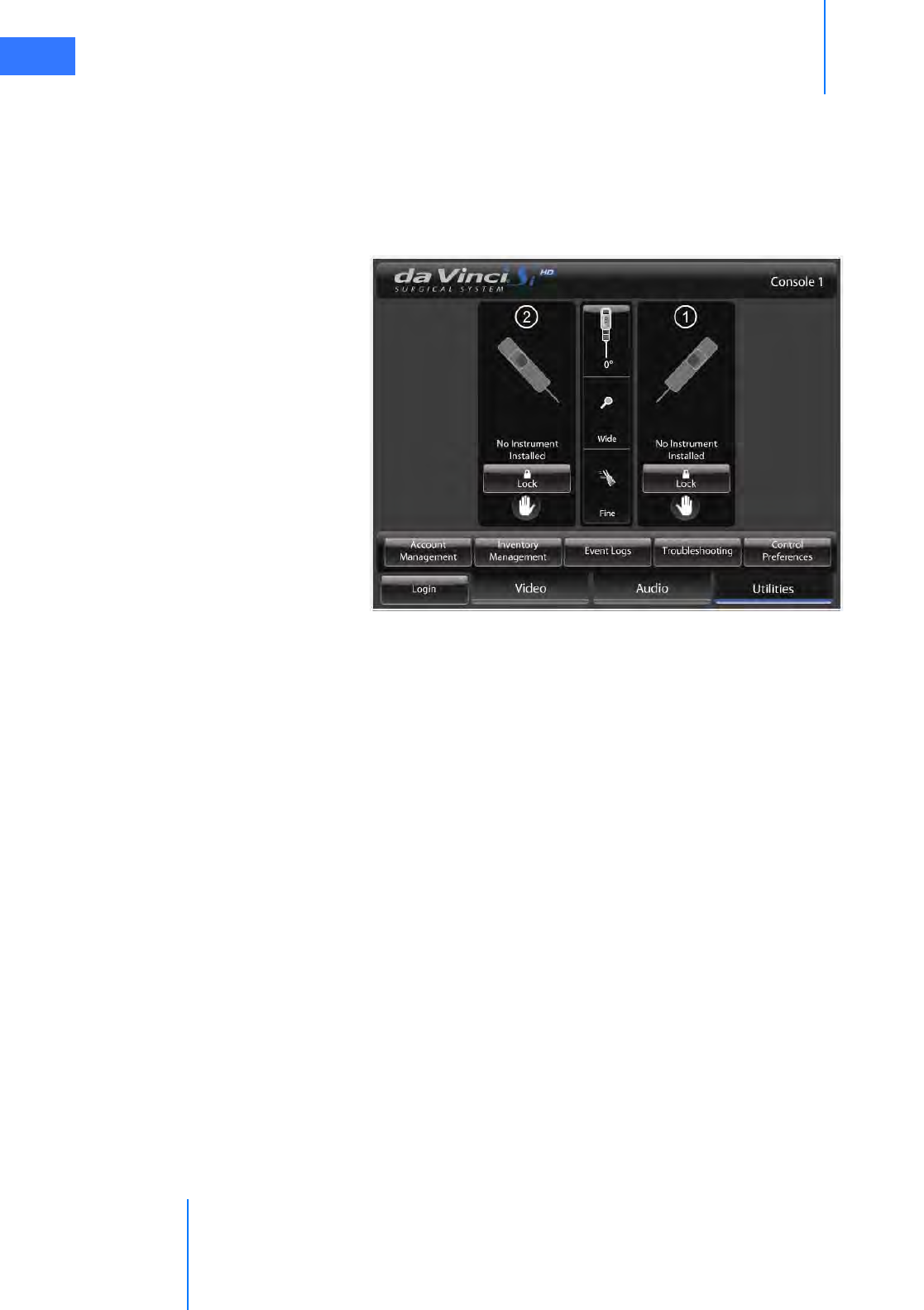
Two Instrument Arms
The da Vinci Si-e System has only two instrument arms, as reflected on the touchpad display:
Figure B.1 Two instrument arms appear on touchpad
Audio System
Since the monitor includes a microphone and speakers, it provides support for two-way audio
communication between the surgeon and patient-side assistant. For the da Vinci Si-e System,
the volume control slider for the Vision Cart speakers is found on the Audio tab of the
touchpad, to the right of the Surgeon Console speaker control. Note that there is no
microphone mute button; to mute the microphone, drag the slider all the way to the left, as
shown.
da Vinci® Si™
Appendix B: da Vinci Si-e Surgical System B-4
DRAFT/PRE-RELEASE/CONFIDENTIAL
10/9/14
Figure B.2 Speaker volume control is on touchpad Audio tab
TilePro Not Available
TilePro (multi-image) mode is not available with the da Vinci Si-e System, and thus the option is
not present on the Display Preferences screen of the touchpad.
Figure B.3 TilePro not present
Surgeon Console
speaker volume
Vision Cart
speaker volume
Appendix B: da Vinci Si-e Surgical System
da Vinci® Si™
B-5
DRAFT/PRE-RELEASE/CONFIDENTIAL
10/9/14
Furthermore, the QuickClick option for TilePro activation is not offered on the touchpad
Control Preferences screen.
Figure B.4 TilePro QuickClick option not present
Telestration Not Available
Since telestration is done on the touchscreen, telestration is not possible with the da Vinci Si-e
System. However, note that the selected Display Eye option on the Display Preferences screen
(Figure B.3) does still determine whether the surgeon’s left (L) or right (R) eye image from the
stereo viewer passes out of the video connectors of the Core’s Video Out bay Aux.
da Vinci® Si™
Appendix B: da Vinci Si-e Surgical System B-6
DRAFT/PRE-RELEASE/CONFIDENTIAL
10/9/14
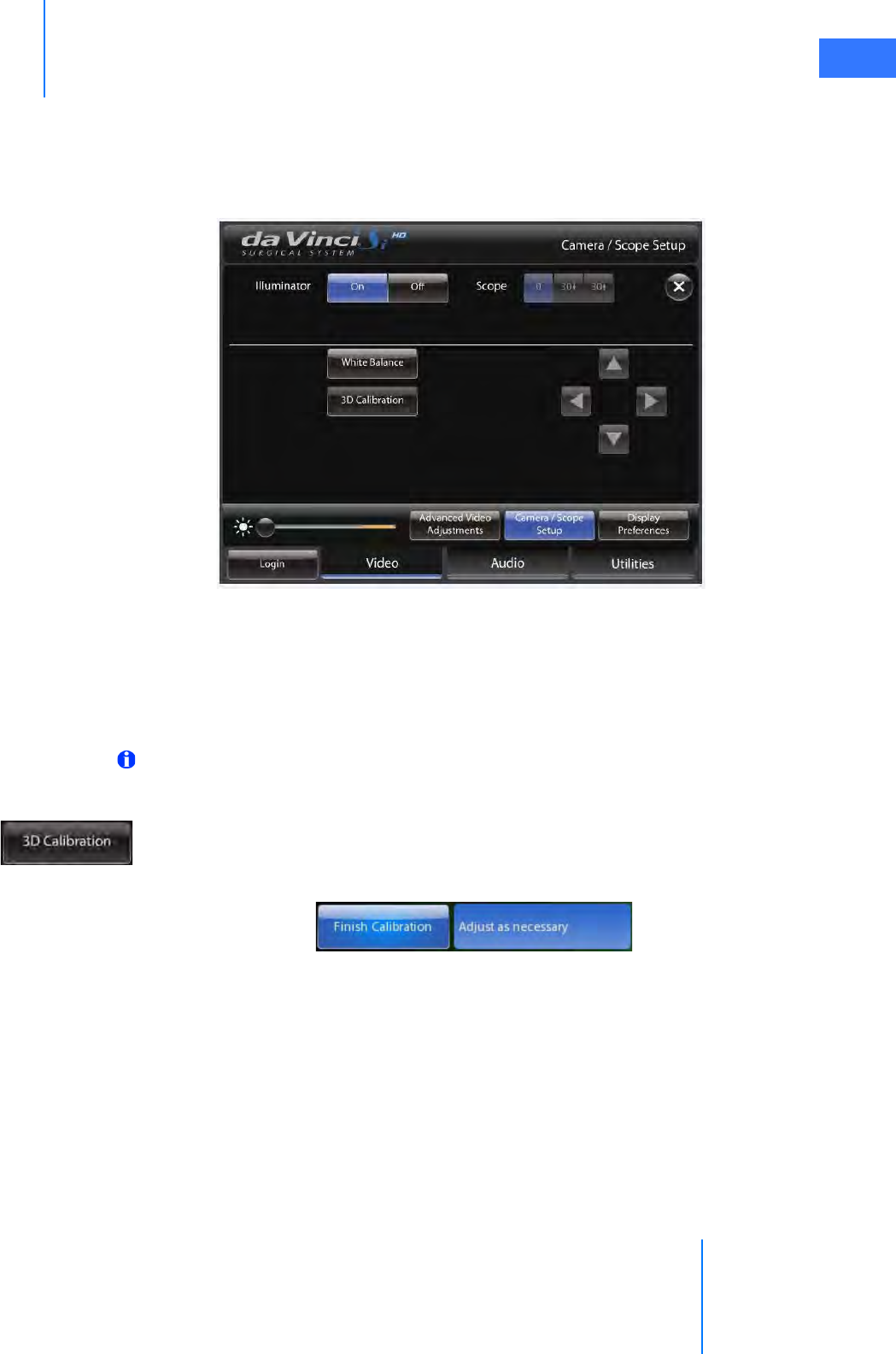
Camera / Scope Setup via Touchpad Only
On the Si-e System, no touchscreen dictates that camera / scope setup must be done via the
touchpad. This circumstance also requires two people to perform calibration: one sterile
person to handle the endoscope and a second non-sterile person to work the touchpad at the
Surgeon Console.
Figure B.5 Camera / Scope Setup on the touchpad
Follow these steps to calibrate the endoscope assembly from the touchpad of a da Vinci Si-e
System:
1. The sterile person should insert the endoscope tip fully inside the endoscope alignment
target, using the proper hole, which depends on the tip angle, so that the target
crosshairs are visible on the center of the stereo viewer.
Note: For 3D calibration to be successful, the crosshairs must be well centered on screen
and the target must be kept as still as possible on the endoscope.
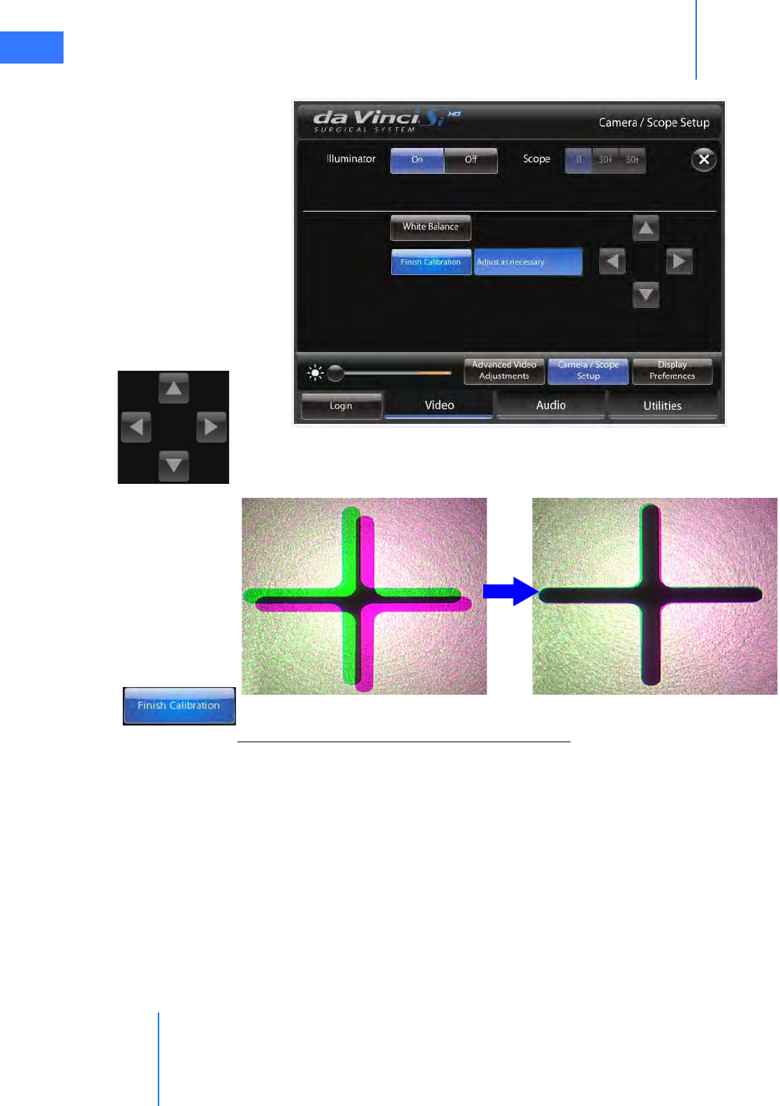
2. The non-sterile person at the touchpad: From the Video tab, go to Camera / Scope
Setup and then touch the 3D Calibration button. The button name changes to Finish
Calibration and “Adjust as necessary” appears next to it, and the button and all arrow
buttons flash to prompt your input.
Appendix B: da Vinci Si-e Surgical System
da Vinci® Si™
B-7
DRAFT/PRE-RELEASE/CONFIDENTIAL
10/9/14
Figure B.6 3D Calibration in progress
3. Touch the arrows on the touchpad to move the green crosshairs until aligned with the
magenta crosshairs, as seen in the stereo viewer.
4. To save the calibration setting and exit calibration mode, touch Finish Calibration.
3D Calibration and Camera Head Button Functionality
For the da Vinci Si-e System, the camera head buttons do not support 3D calibration. Without a
touchscreen, you must perform 3D calibration from the touchpad, as described above. The
Vision Setup button, in particular, supports no functionality at all; when you press it the
system gives an error beep, but does not display a message. Nothing happens except the error
beep. The Focus In and Out arrow buttons still support focusing of the surgical image from
the camera head, and the Lamp On/Off button still functions.
_________________________________End of section______________________________
da Vinci® Si™
Appendix C: Illuminator Information C-1
DRAFT/PRE-RELEASE/CONFIDENTIAL
10/9/14
CAppendix C: Illuminator Information
This appendix provides detailed information and specifications for the integrated Illuminator,
also known as the Y1903 Xenon Fiber-Optic Light Source.
C.1 General Safety Precautions
Before operating, read all safety instructions. See Endoscopic Procedure Precautions on page
10 for additional safety instructions regarding use of the Illuminator. The Illuminator is a
source of high electrical voltage, intense light and heat. When used properly and with normal
precautions, it is a safe and effective light source.
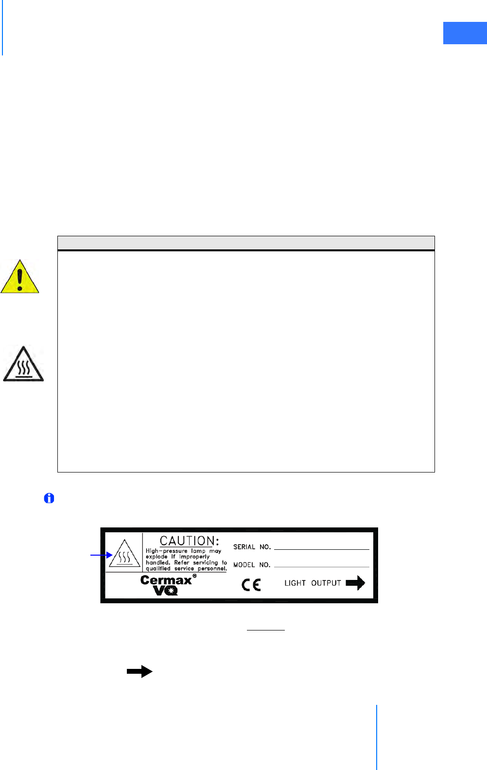
The following label appears on the side of the lamp module above the removal handle.
Note: It may be necessary for the reader to be as close as 6 in (15 cm) from the label to
read this information.
Figure C.1 Lamp module label
Observe the caution statement on the label: “CAUTION: High-pressure lamp may explode if
improperly handled. Refer servicing to qualified service personnel.”
The label provides space to indicate the “SERIAL NO.” and “MODEL NO.” of the lamp module.
“LIGHT OUTPUT ” indicates that the lamp light emits from the side indicated by the
arrow.
CAUTION:
Third party light guides may not withstand light output levels of this light source.
Do not operate the light source without lamp module in place.
Disconnect power supply cord before servicing to avoid electric shock.
To reduce risk of electric shock, do not remove cover. Refer servicing to Intuitive
Surgical personnel.
CAUTION HOT. Do not remove lamp immediately after operation. Allow lamp to cool 5
minutes with fans running before removing power to the Illuminator.
The end of the light guide may be hot.
Keep cooling vents free from obstructions.
To prevent overheating, replace only with the same type and rating of lamp module.
Read instructions before replacing lamp module. (See 12.3 Illuminator Lamp Module
Replacement on page 12-2.)
Caution: Hot
Appendix C: Illuminator Information
da Vinci® Si™
C-2
DRAFT/PRE-RELEASE/CONFIDENTIAL
10/9/14
Refer to Figure 12.2 on page 12-4 to see an image of the lamp module replacement label
affixed to the top of the lamp module.
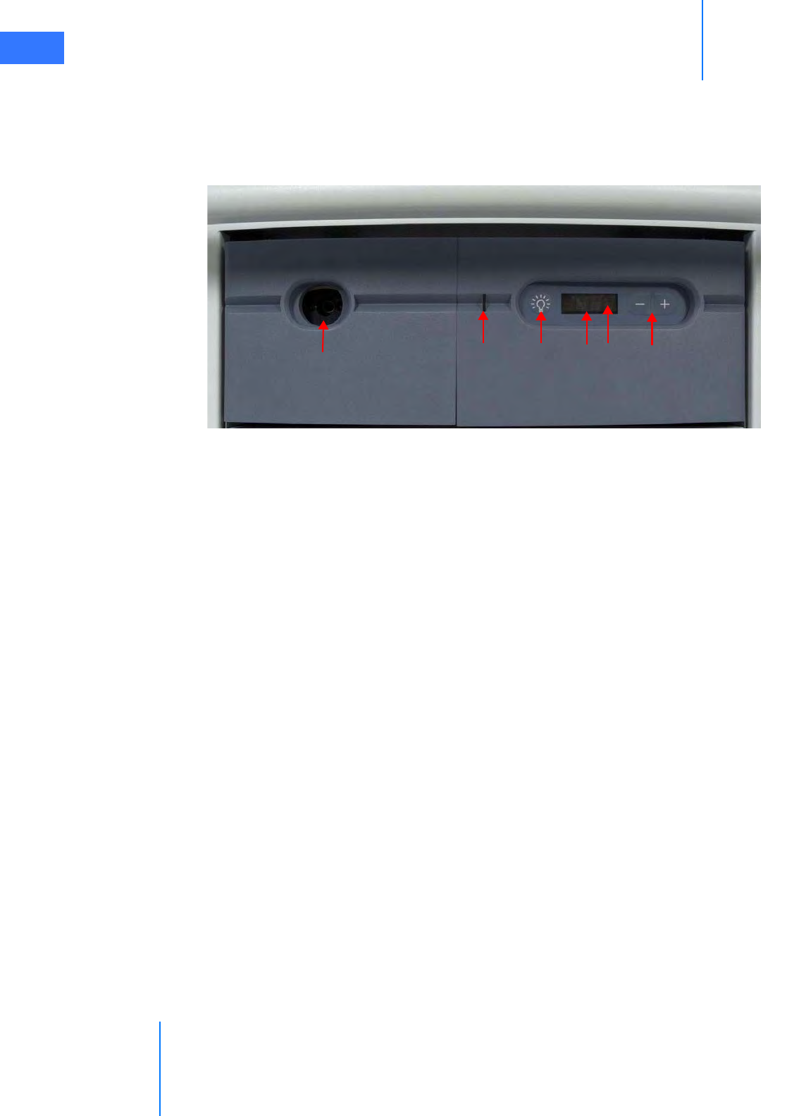
C.2 Illuminator Features
Figure C.2 Illuminator front features
1. Optic Adapter: Accepts Olympus™ fiber-optic light cables.
2. LED Indicator: Shows the lamp status. Amber: Lamp off; Blue: Lamp on; Blue blinking: No
scope selected or detected.
3. Lamp On/Off Switch: Toggles the lamp on/off once the system has been powered up.
This button switch on the front panel is symbolized by an incandescent lamp. When
pushed, the blue “OFF” flashes on the display until lamp ignition occurs.
4. Display Window: Displays light output level from 0-100 in 10% increments when lamp is
on, and will read OFF when lamp is off.
5. Lamp Hours: Displays number of usage hours on the lamp module. To read the lamp
hours, press the decrease (–) and increase (+) buttons simultaneously, and read the
number displayed on the display window. You may also view lamp hours by selecting
Utilities > Inventory Management on the touchscreen or touchpad, as described in
sections 7.2 and 10.3.
6. Intensity Control (– +): Control buttons to increase or decrease light output levels in
10% increments.
123456
da Vinci® Si™
Appendix C: Illuminator Information C-3
DRAFT/PRE-RELEASE/CONFIDENTIAL
10/9/14
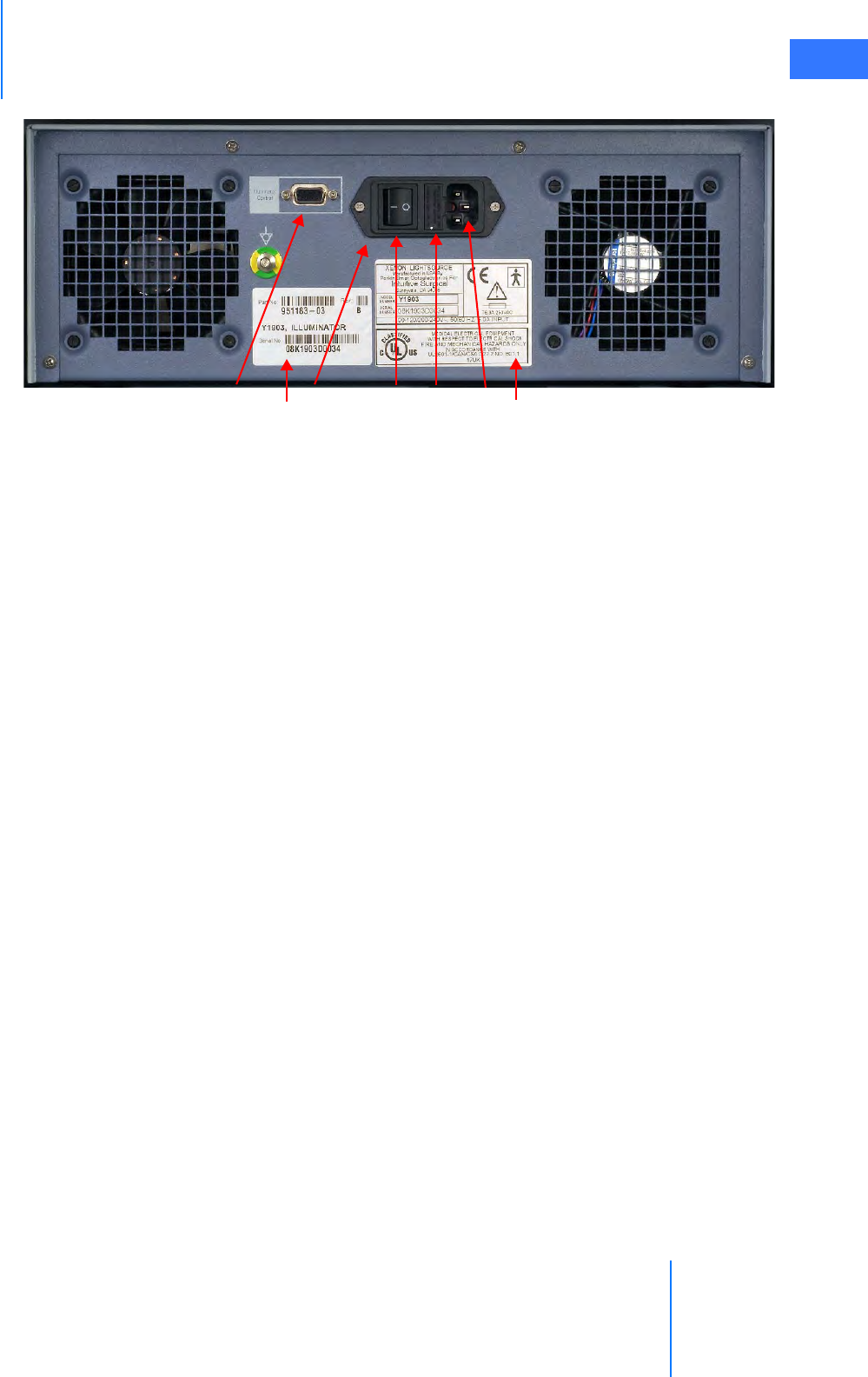
Figure C.3 Illuminator rear features
7. RS232 I/O Serial Port: 9-pin D Sub-Miniature interface for RS232 control features.
Labeled “Illuminator Control.”
8. Input Power Module: Consists of the Power On/Off switch, fuse drawer, and AC input
power receptacle.
9. Power On/Off Switch: The Power On/Off Switch is located on the back panel. When
switched ON, the system is energized and initiates standby mode, while the LED indicator
(on front) illuminates amber. In addition, the cooling fans run, and the display reads OFF.
When switched OFF, the system is de-energized, the LED indicator (on front) is not
illuminated, and the display is dark. Energizing the system does not automatically turn
the lamp on.
10. Fuse Drawer: The fuse drawer is located on the back panel beside the AC input power
receptacle. The fuse drawer contains two 6.3 amps main fuses.
11. AC Input Power Receptacle: The AC input power receptacle, located on the back panel,
is a three-prong receptacle that accepts a detachable AC power cord.
12. Unit Identifier Label
13. Light Source Label: Shown below.
78 91011
13
12
Appendix C: Illuminator Information
da Vinci® Si™
C-4
DRAFT/PRE-RELEASE/CONFIDENTIAL
10/9/14
Note: It may be necessary for the reader to be as close as 6 in (15 cm) from the label to
read this information.
Figure C.4 Light source label example
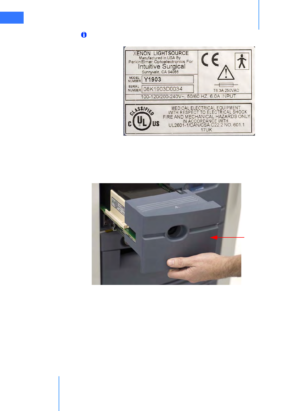
14. Lamp Module Access Drawer: Allows service technician access to the lamp module for
replacement. (See 12.3 Illuminator Lamp Module Replacement on page 12-2.) By pushing
in on the drawer, the latch mechanism will release, and the drawer will slide forward. To
close the drawer, push it in until the latch catches.
Figure C.5 Lamp module access drawer open
14. Lamp module
access drawer
da Vinci® Si™
Appendix C: Illuminator Information C-5
DRAFT/PRE-RELEASE/CONFIDENTIAL
10/9/14
C.3 Basic Troubleshooting
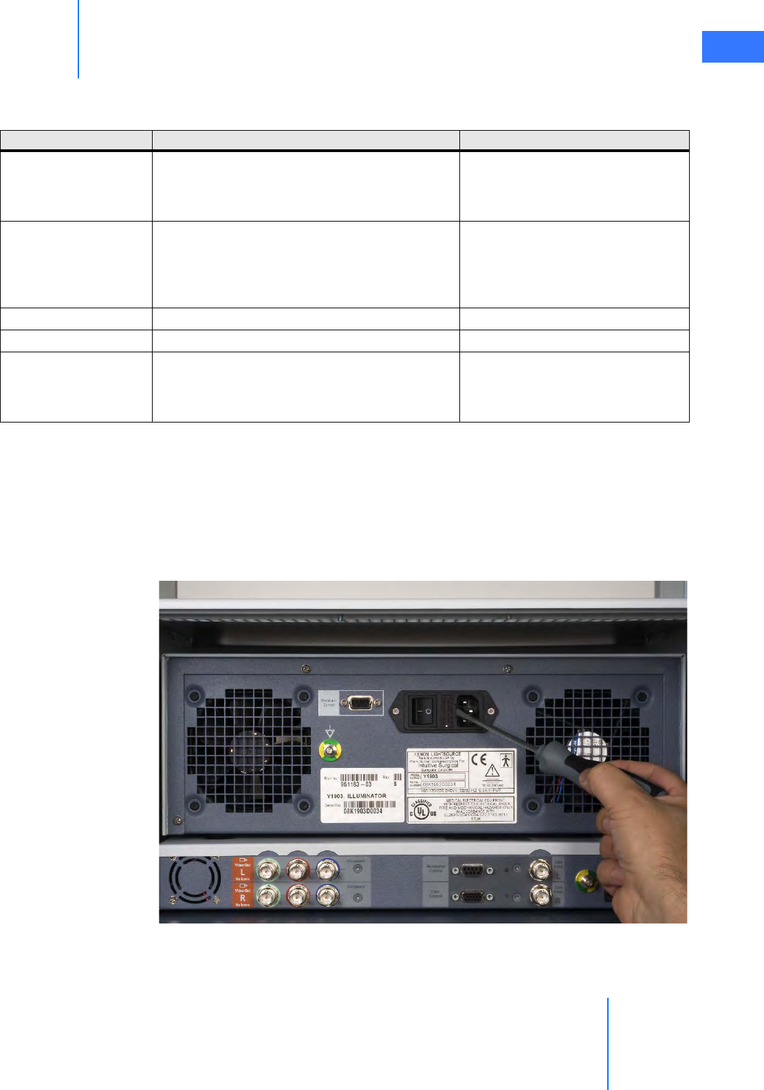
C.4 Fuse Replacement
1. Switch power off on the back of the Illuminator and remove the power cord from the
back of the Illuminator.
2. Check for blown fuses by removing the fuse cover, located next to the three-prong power
receptacle. Carefully pull out the cover using a flat blade screwdriver (medium size) or
equivalent, as shown in Figure C.6.
Figure C.6 Remove fuse cover
3. Replace blown fuse(s) with the same size and rating: 6.3A time delay: T6.3A fuses, size
5x20mm.
Table C-1 Basic Troubleshooting
Symptom Possible Problems Remedy
No power to Illuminator
• Vision Cart not connected or not powered on.
•Fu
se is blown.
• Internal power supply not operating.
• AC input power receptacle unplugged.
• Connect and power on system.
•Replace fuse.
• Contact Intuitive Surgical Technical
Support.
No light emits from unit
• Lamp module access drawer open.
•Lamp burned out.
• Internal power supply not operating.
• Fiber-optic cable not connected.
•Close drawer.
• Replace lamp module.
• Contact Intuitive Surgical Technical
Support.
• Connect fiber-optic cable correctly.
Lamp flickers or dims Lamp is getting old. Replace lamp module.
Field of view is dim Incorrect settings. Adjust Brightness controls
Illuminator turns off
after a few minutes of
operation.
• Obstructed air intake leads to overheating, causes
thermal switch to trip.
• Fan not running; overheating causes thermal
switch to trip.
• Allow unit to cool 10 minutes.
Remove obstructions.
• Contact Intuitive Surgical Technical
Support.

Appendix C: Illuminator Information
da Vinci® Si™
C-6
DRAFT/PRE-RELEASE/CONFIDENTIAL
10/9/14
4. Re-install the fuse cover.
5. Reconnect the power cord
6. On the back of the Illuminator, turn the power switch on. The Illuminator should be
operative again.
Contact Intuitive Surgical Technical Support if the unit fails to operate properly again.
C.5 Specifications of Y1903 Light Source
Note: The specifications in this section apply to the Y1903 Illuminator only and not the
da Vinci Si System.
Table C-2 Y1903 Light Source Specifications
Category Specification Comments
Electrical Input
Input Voltage 100 - 240 VAC, 50/60Hz universal, 6.0A input
AC Power Connector Located on rear panel, dual fuses
Line Cord IEC320, 6’ (1.83m), configured for locale
Performance and Features
Light Output
• 2450 Lumens nominal initial output using
Olympus™ fiber.
• Spectral output 386 - 733nm nominal
• <10% instability p-p through 6 mm glass rod @
0-100Hz
• Beam profile to have “smooth” distribution with no
shadows or sharp peaks
All light output specifications
refer to “system only”
performance. Light output via
optical fibers or other optical
components may vary.
Over-temperature
Protection
Automatic shutdown in the event of overheating
Overheat Recovery / Auto
Cool
Unit to become fully operational <3 minutes
(target) after thermal shutdown and all
obstructions to air flow removed at
environmental temperature of <22 °C (72 °F)
Fans will remain on in the event
of thermal shutdown when
power is on. Lamp must be
switched on by using Lamp
On/Off switch located on front
panel.
Fiber-Optic Connection
Safety Feature
• Lamp will not ignite unless a fiber-optic cable is
fully inserted into the active port on the turret
• Lamp power is cut or blocked if fiber-optic cable is
removed from active port to prevent accidental
light leakage
Fans will remain on in the
absence of a fiber-optic cable
inserted into active port when
power is on
Lamp Power Supply PS300-12 type
Lamp Module Cermax VQ (300 Watt) Intuitive Surgical PN 950093
Lamp Module Replacement
By easy access to lamp module via drawer. No
tools required.
Lamp replacement drawer
“interlocked” for safety. Lamp
power will be cut when drawer
is opened
Lamp Life
• 1000 hours to 50% of initial output specification
measured through 6 mm glass rod
• >1000 hours at a minimum output of 1225 Lumens

da Vinci® Si™
Appendix C: Illuminator Information C-7
DRAFT/PRE-RELEASE/CONFIDENTIAL
10/9/14
User Interface / Control
User instructions In this system user manual
Lamp On/Off Switch
Located on front panel User controlled lamp on/off. Fan
operation independent of lamp
status.
Fiber-Optic Adapter Olympus™ port to fit Olympus fiber
Light Attenuation Shutter
• Controlled by membrane buttons on front panel
•(+) and (–) buttons for relative intensity increments
• Relative level of illumination indicated by a digital
numeric display (blue numerals)
Lamp Hour Counter
Displays number of elapsed hours of lamp
operation when you press (+) and (–) buttons at
same time
Mechanical & Environmental
Dimensions Height 5.5" (Without Feet) x Width 15.5" x Depth
≤17” (without front bezel) (14 x 39.4 x 43.2cm)
Designed for modular
expansion
Weight ≤28 lbs.
Touch Temperature Per UL60601 -1
Ground Bound Per UL60601 –1
Sterilization
The light source may be wiped-down with
hospital approved disinfectants (for example,
10% bleach + 90% water solution) applied with a
damp cloth (must not be wet)
Operating Temperature 6 °C to 35 °C
Storage Temperature –20 °C to 75 °C
Operating & Storage
Humidity
10 - 80% relative humidity, non-condensing
Operating Pressure 1 Atmosphere
Audible Noise ≤ 40dB
Shipping, Shock &
Vibration
per ISTA 3A
Cooling Vents to direct airflow toward the back of the
unit
Regulatory Approvals
Compliance to standards
• IEC 60601-1:1988+A1:1991+A2:1995+A1.3:1997
• UL 60601-1:2003
• EN 60601-1:1990+A1:1993+A2:1995+A1.3:1997
• EN 60601-1-2:2001
• CAN / CSA C22.2 No. 601.1/M90(R1997),B/98,S1-94
• ANSI/AAMI ES60601-1: 2005
• CAN/CSA-22.2 No. 60601-1 (2008)
• EN 60601-1-2: 2007
•CE mark
Table C-2 Y1903 Light Source Specifications
Category Specification Comments

Appendix C: Illuminator Information
da Vinci® Si™
C-8
DRAFT/PRE-RELEASE/CONFIDENTIAL
10/9/14
C.6 Classification of the Y1903 Light Source
• Class I: The light source relies on connection to the protective earth conductor to prevent
shock hazards.
• Type BF: The Y1903 light source is classified as a BF equipment. The optic adapter is
grounded and only BF or CF applied parts should be used with the Y1903.
Note: The da Vinci Si camera head provides isolation in accordance with a CF applied
part and is acceptable for use with the Y1903 Illuminator.
• Provides no protection against ingress of liquids.
• Mode of Operation: Suitable for continuous operation.
• Not suitable for use in the presence of a flammable anaesthetic mixture with air or with
oxygen or with nitrous oxide.
C.7 Electromagnetic Compatibility
The Y1903 has been tested and found to comply with the limits for medical devices to the IEC
60601-1-2:2001(E). These limits are designed to provide reasonable protection against
harmful interference in a typical medical installation. The Y1903 generates, uses and can
radiate radio frequency energy and, if not installed and used in accordance with the
instructions, may cause harmful interference to other devices in the vicinity. However, there is
no guarantee that interference will not occur in a particular installation. It can be determined
if this equipment causes interference by turning the power to the light source off and on. The
user is encouraged to try to alleviate interference problems by one or more of the following
measures:
• Re-orient or relocate the receiving device
• Increase the separation between the equipment.
• Connect the equipment into an outlet on a separate electrical circuit from that of other
devices.

da Vinci® Si™
Appendix C: Illuminator Information C-9
DRAFT/PRE-RELEASE/CONFIDENTIAL
10/9/14
Warnings
• AC power cords other than those provided with the instrument may result in increased
emissions or decreased immunity.
• The Y1903 should not be used adjacent to or stacked with other equipment. However, if
adjacent or stacked use is necessary, the Y1903 should be observed to verify normal
operation in the configuration in which it is used.
Manufacturer’s declaration – electromagnetic immunity
The Y1903 is intended for use in the electromagnetic environment specified below. The customer or the user
of the Y1903 should assure that it is used in such an environment.
Immunity Test IEC 60601 Test Level Compliance Level Electromagnetic
Environment Guidance
Electrostatic discharge
(ESD)
IEC 61000-4-2
±6 kV contact
±8 kV air
Complies Floors should be wood,
concrete or ceramic tile. If
floors are covered with
synthetic material, the
relative humidity should
be at least 30%.
Electrical fast
transient/burst
IEC 61000-4-4
±2 kV for power supply
lines ±1 kV for input/
output lines
Complies Mains power quality
should be that of a typical
commercial or hospital
environment.
Surge
IEC 61000-4-5
±1 kV line(s) to line(s)
±2 kV line(s) to earth
Complies Mains power quality
should be that of a typical
commercial or hospital
environment.
Voltage dips, short
interruptions and voltage
variations on power supply
input lines
IEC 61000-4-11
<5% UT (>95% dip in UT)
for 0.5 cycle
40% UT (60% dip in UT) for
5 cycles
70% UT (30% dip in UT) for
25 cycles
<5% UT (>95% dip in UT)
for 5 sec.
Complies Mains power quality
should be that of a typical
commercial or hospital
environment. If the user of
the Y1903 requires
continued operation
during power mains
interruptions, it is
recommended that the
Y1903 be powered from
an uninterruptible power
supply or battery.
Power frequency (50/60
Hz) magnetic field
IEC 61000-4-8
3 A/m Complies Power frequency
magnetic fields should be
at levels characteristic of a
typical location in a typical
commercial or hospital
environment.
Note: UT is the AC mains voltage before application of the test level.
Appendix C: Illuminator Information
da Vinci® Si™
C-10
DRAFT/PRE-RELEASE/CONFIDENTIAL
10/9/14
_________________________________End of section______________________________
Manufacturer’s Declaration – Electromagnetic Emissions
The Y1903 is intended for use in the electromagnetic environment specified below. The customer or the user
of the Y1903 should assure that it is used in such an environment.
Emissions test Compliance Electromagnetic environment guidance
RF emissions
CISPR 11
Group 1 The Y1903 uses RF energy only for its internal
function. Therefore, its RF emissions are very low
and are not likely to cause any interference in
nearby electronic equipment.
RF emissions
CISPR 11
Class B The Y1903 is suitable for use in all establishments,
including domestic and those directly connected
to the public low-voltage power supply network
that supplies buildings used for domestic
purposes.
Harmonic emissions IEC 61000-3-2 Class B
Voltage fluctuations/ flicker
emissions IEC 61000-3-3
Complies
da Vinci® Si™
Appendix D: VisionBoom™ Use Instructions D-1
DRAFT/PRE-RELEASE/CONFIDENTIAL
10/9/14
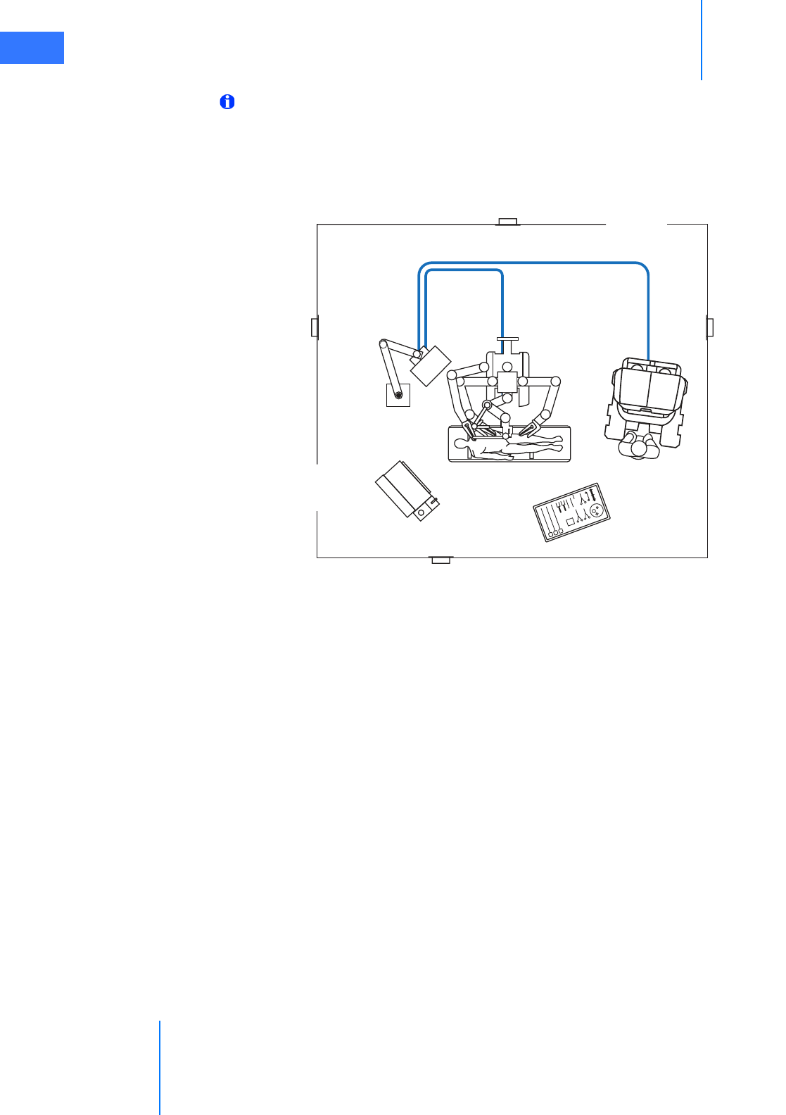
DAppendix D: VisionBoom™ Use
Instructions
This appendix provides instructions to use the da Vinci Si Surgical System installed in the
VisionBoom configuration. Integrators seeking installation instructions should refer to the
VisionBoom™ Installation Guide (PN 550539).
Note: This appendix provides only those instructions specific to the VisionBoom
configuration. Refer to relevant portions of this manual for instructions to use the
surgical system.
The da Vinci Si VisionBoom configuration eliminates clutter and improves efficiency in
operating room (OR) surgical environments by replacing the da Vinci Vision Cart, and its
associated cords and cables, with a convenient ceiling-mounted system.
Figure D.1 Recommended side by side (left) and stacked (right) VisionBoom configurations
Note: The VisionBoom upgrade supports dual console surgery.
The ceiling-mounted equipment boom is the primary platform for OR integration and,
depending on the model selected, the typical boom can provide the support and space to
position most necessary clinical devices. The equipment boom is not a product sold by ISI but
by manufacturers such as Berchtold™, Steris™, Skytron™, etc., to name just a few vendors that
sell such equipment.

Appendix D: VisionBoom™ Use Instructions
da Vinci® Si™
D-2
DRAFT/PRE-RELEASE/CONFIDENTIAL
10/9/14
D.1 General Notes and Cautions
Note:
• Air flow sufficient to support adequate cooling of da Vinci vision components is
critical to their proper function. The entire da Vinci System is designed to
undergo an automatic, controlled power-down sequence in case a component
or subsystem overheats while in normal operating mode, thereby preventing
system damage. (See Chapter 5 Startup for details.) To avoid overheating, do not
place anything on or near any da Vinci vision component on the boom,
especially if it might impede air flow. Do not route cables behind the Illuminator
on the boom shelf, to avoid blocking air flow behind it.
• ISI recommends that the boom be oriented during surgery so that air flow from
the components is directed away from the sterile field.
•ISI recommends that da Vinci vision components be left permanently in the
configuration in which they are transferred to the boom by ISI service
personnel. Rearrangement of da Vinci vision components could result in a
configuration that does not support adequate cooling or otherwise may result
in an increased risk of damage to or improper function of the components.
•da Vinci vision components are not designed to support external loads, and
therefore ISI discourages placement of any equipment on top of da Vinci vision
components mounted on the boom shelf.
CAUTION: To avoid overloading circuits, do not connect ancillary devices such as
insufflators or energy devices in common circuits with any system component,
particularly not with the vision components because they have large power
requirements. Ancillary devices must be connected to boom outlets on separate circuits
from all system components.
CAUTION: After a few minutes of use, the rear of da Vinci vision components may
become hot, particularly the Illuminator. Avoid touching the rear of these units during
use and for 10 minutes after use while components cool with internal fan operation.
D.2 da Vinci Si System Connections
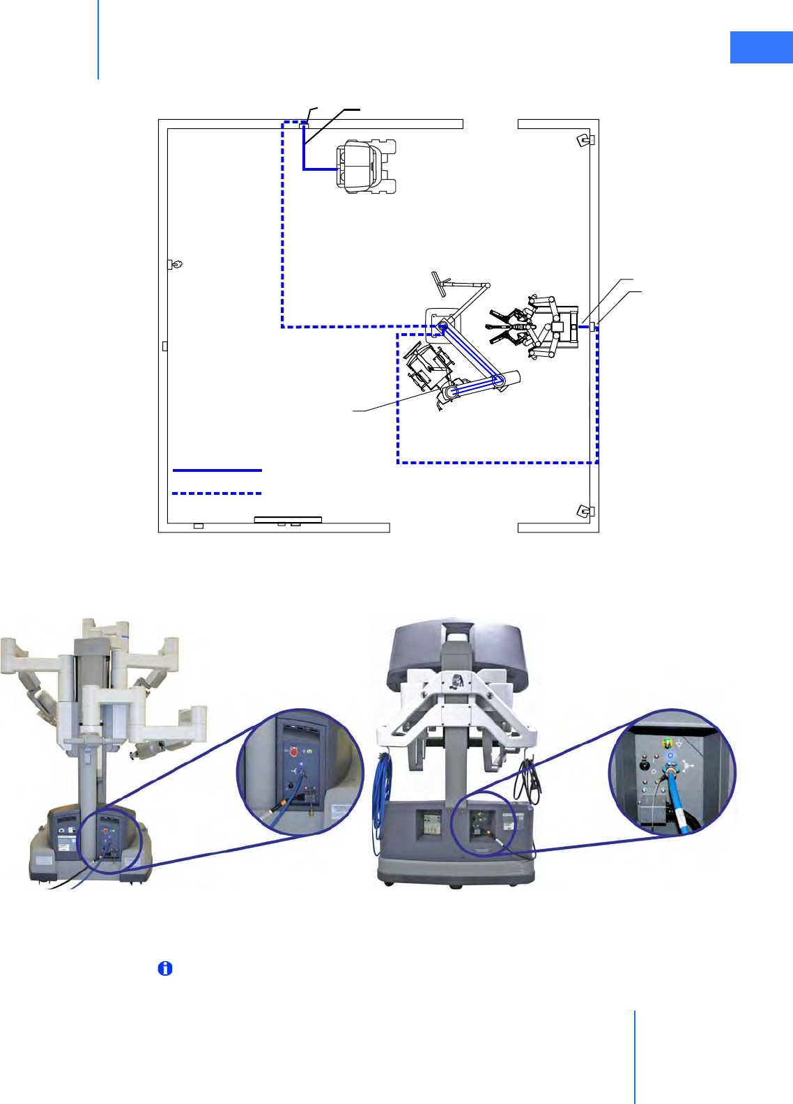
In a VisionBoom configuration, Surgeon Consoles and the Patient Cart connect to the Core via
fiber interface wall plates. These wall plates connect via cabling inside the wall that terminates
in the fiber boom plates, which connect via their blue cables (1 m) directly to the back of the
Core. Surgeon Consoles and the Patient Cart can connect to any da Vinci wall plate in the
room. The Core recognizes the units connected to its fiber input ports automatically. Figure
D.2 illustrates how the system connections are made.
da Vinci® Si™
Appendix D: VisionBoom™ Use Instructions D-3
DRAFT/PRE-RELEASE/CONFIDENTIAL
10/9/14
Figure D.2 Fiber cables and conduits connect Core to Patient Cart and Surgeon Consoles
Figure D.3 shows where to find the fiber optic cable connectors on the rear of the Patient Cart
and Surgeon Console.
Figure D.3 Fiber connectors on Patient Cart and Surgeon Console
Connecting the Fiber Cables
Note: The connections on the back of the Core (in Step 4: Connect Core, page 5) generally
are made only once and left connected unless the Core is removed from the boom.
da Vinci
da Vinci
Wall plate Fiber cable
Fiber cable
Wall plate
Equipment boom
Patient Cart
Surgeon Console
Boom plates
with Core
Fiber cable
Fiber conduit through
walls/ceiling
Appendix D: VisionBoom™ Use Instructions
da Vinci® Si™
D-4
DRAFT/PRE-RELEASE/CONFIDENTIAL
10/9/14
Follow these steps to connect the Patient Cart and one or two Surgeon Consoles to the Core in
the VisionBoom configuration.
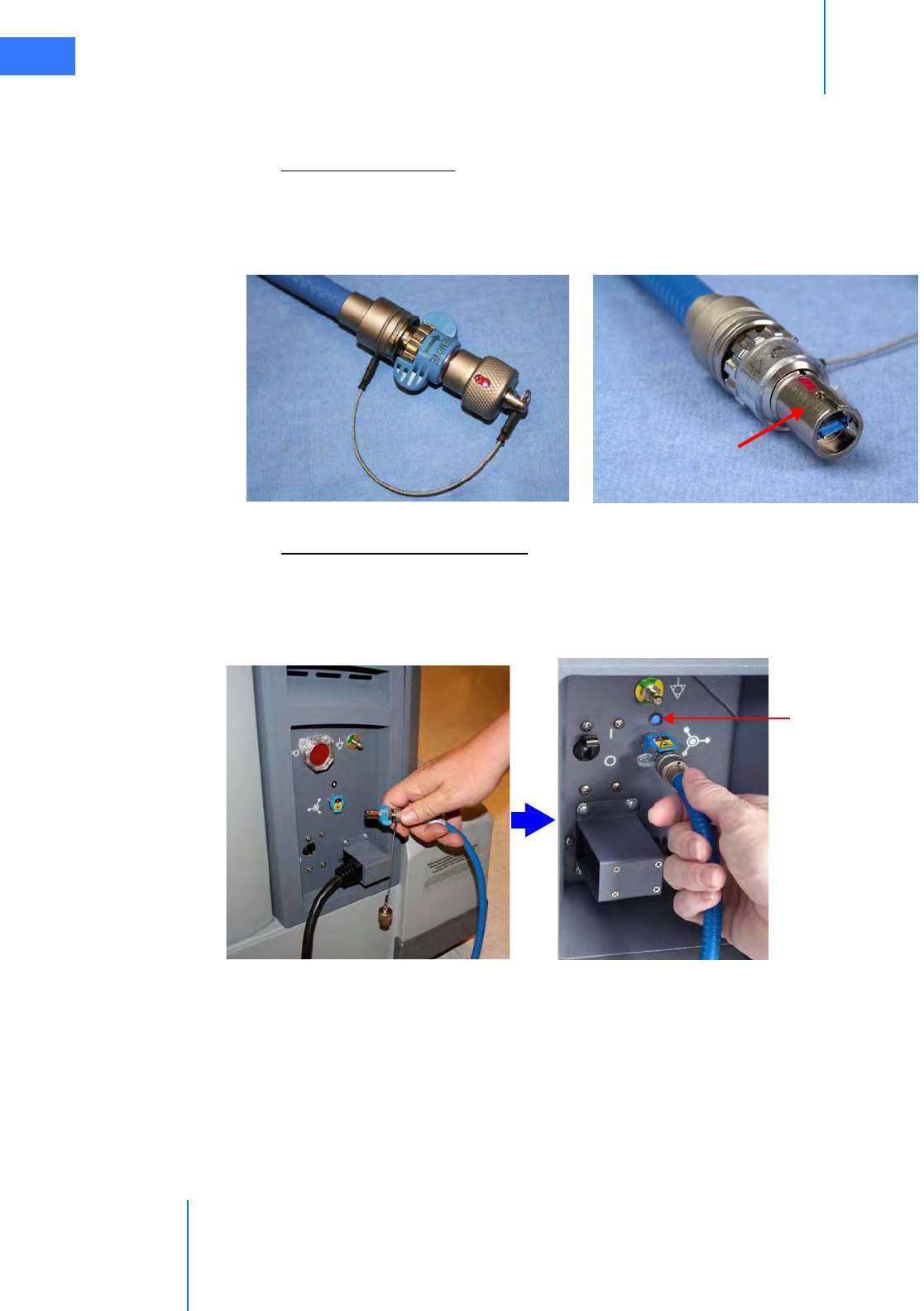
Step 1: Remove Cap
Before connecting the blue da Vinci Si fiber cables, pull to remove the protective cap at each
end of the cable (Figure D.4). Note the position of the red alignment mark on the uncapped
cable end, which you must align with a similar mark on the fiber cable port for successful
insertion.
Figure D.4 Remove the cable end cap
Step 2: Connect Patient Cart
Connect a blue fiber cable (20 m) to the back of the Patient Cart (Figure D.5) and to the desired
fiber interface wall plate (Figure D.6). When lit solid blue, the LED above the fiber port
indicates a good connection to the Core. (It will not light blue until you complete the
connection from the boom plate to the Core – see Step 4: Connect Core, page 5.)
Figure D.5 Connect fiber cable to Patient Cart
End cap on system cable Uncapped end of cable
Red alignment mark
Observe red mark and align Flip up receptacle cover & insert
Blue light shows
good connection
when complete to
Core
da Vinci® Si™
Appendix D: VisionBoom™ Use Instructions D-5
DRAFT/PRE-RELEASE/CONFIDENTIAL
10/9/14
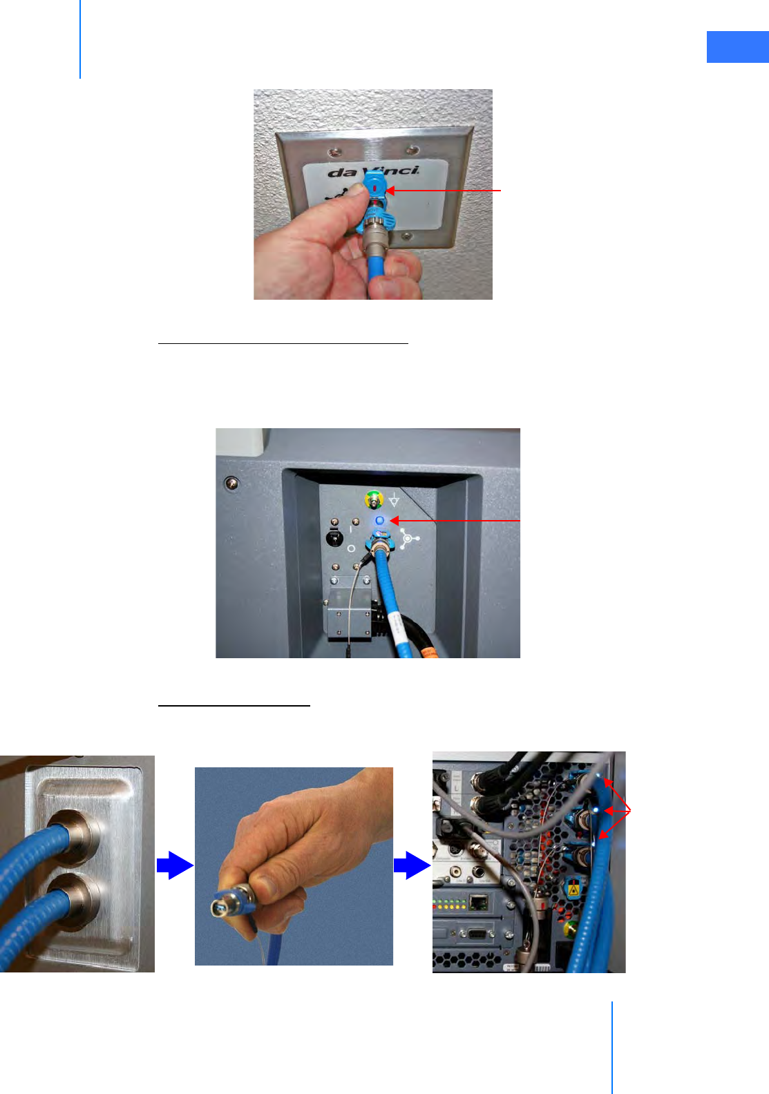
Figure D.6 Connect other end of fiber cable to fiber wall plate
Step 3: Connect Surgeon Consoles
For each Surgeon Console you will use, connect a fiber cable to the fiber connector on the
back of the console (Figure D.7) and to an available fiber wall plate (as in Figure D.6). Again, a
blue LED indicates a good connection to the Core when connections in next step are
complete.
Figure D.7 Connect fiber cables to each Surgeon Console
Step 4: Connect Core
Connect each 1 m (3’-3”) cable being used from its boom plate to the back of the Core to
complete the connections for each Surgeon Console and the Patient Cart (Figure D.8).
Figure D.8 Connect the boom plate fiber cables to the Core on the boom
Align red marks and
push in to connect
Blue light shows
good connection
when complete to
Core
Blue LEDs
show good
connections
Appendix D: VisionBoom™ Use Instructions
da Vinci® Si™
D-6
DRAFT/PRE-RELEASE/CONFIDENTIAL
10/9/14
Note: If, after connecting all cables as shown in steps 1 through 4, you still do not have a
good connection (no blue light) connect the long (20 m) blue fiber cables directly to the
core. These blue fiber cables are of sufficient length (20 m) to bypass the wall cabling
and connect directly to the core from the surgeon console and patient cart, as illustrated
in Figure D.9 below.
Figure D.9 Bypassing wall cabling
da Vinci® Si™
Appendix D: VisionBoom™ Use Instructions D-7
DRAFT/PRE-RELEASE/CONFIDENTIAL
10/9/14
D.3 Optional Core Connections
This section describes the additional, optional connections you can make between the Core
and third party devices.
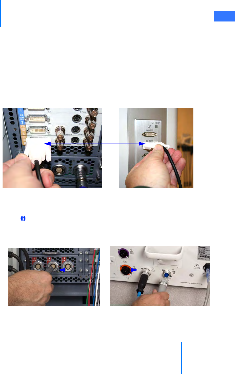
Core Video Connections
Perform this step for each video connection you wish to make between the da Vinci Si System
and external monitors, recorders or other third party devices.
1. Connect each video output or TilePro input on the back of the Core to the desired
interface plate, monitor, or third party device. Figure D.10 shows a typical connection
from the DVI output to a DVI boom interface plate that supports connection to an OR
video switching system.
Figure D.10 Example of DVI connection from Core to boom plate
Electrosurgical Unit (ESU) Connections
Note: Refer to 4.4 Auxiliary Device Connections, page 4-9, for detailed instructions.
To connect one or more electrosurgical units (ESU), perform this step:
1. Connect the appropriate energy activation cable between any of the Energy receptacles
on the back of the Core and the appropriate connectors on the ESU.
Figure D.11 Example of ESU connection to Core
Core DVI output DVI boom plate
Sample ESU connectionsCore Energy connection
Appendix D: VisionBoom™ Use Instructions
da Vinci® Si™
D-8
DRAFT/PRE-RELEASE/CONFIDENTIAL
10/9/14
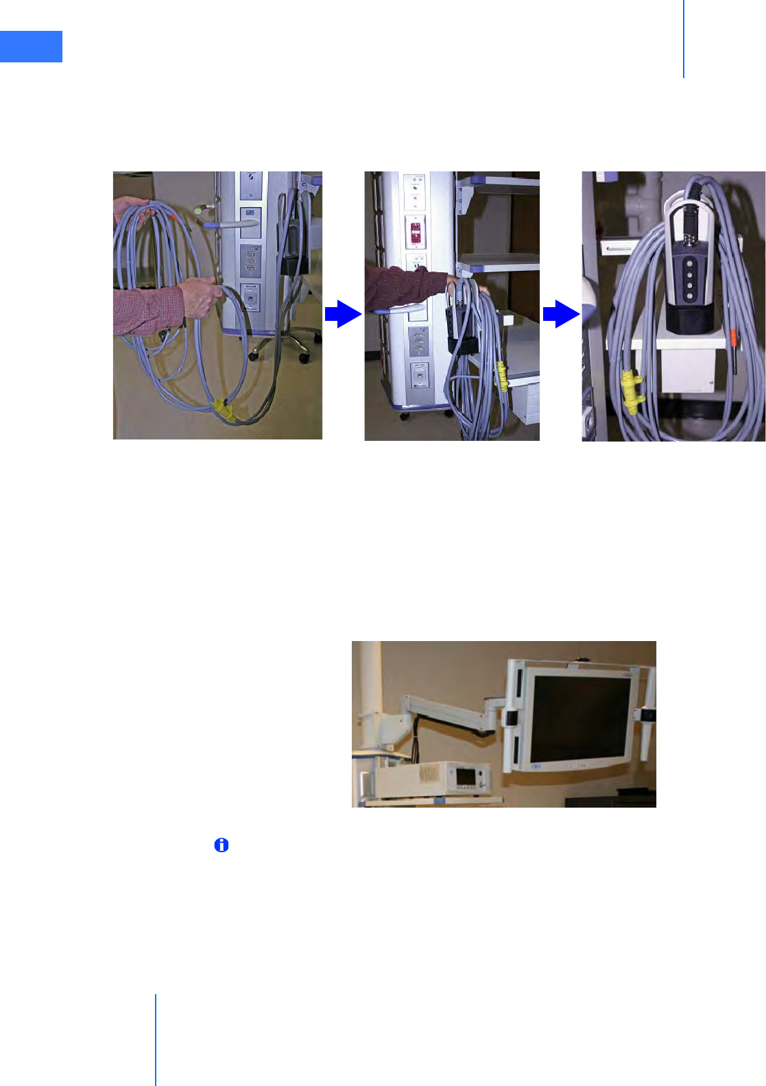
D.4 Camera Head and Cable Storage
The camera holster is installed on the boom to provide a convenient location for storing the
camera head (without endoscope attached) when not in use. Figure D.12 illustrates how to
coil the cables and store the camera head.
Figure D.12 Camera and cable storage using the boom-mounted holster
D.5 Touchscreen Positioning
The da Vinci Si touchscreen mounted on the boom can be positioned to either side of the
boom or directly off the front (Figure D.13). Position it according to the needs of the surgical
staff. Unless a sterile monitor drape is used, a sterile assistant requires a change of surgical
gloves after touching the touchscreen; alternatively, non-sterile surgical staff may operate an
undraped touchscreen.
Figure D.13 You can position touchscreen
Note: Refer to 7.4 Working with the Touchscreen Vision Controls, page 7-15, for
instructions to use the touchscreen.
Coil camera cables Hang cables over holster As when finished
da Vinci® Si™
Appendix D: VisionBoom™ Use Instructions D-9
DRAFT/PRE-RELEASE/CONFIDENTIAL
10/9/14
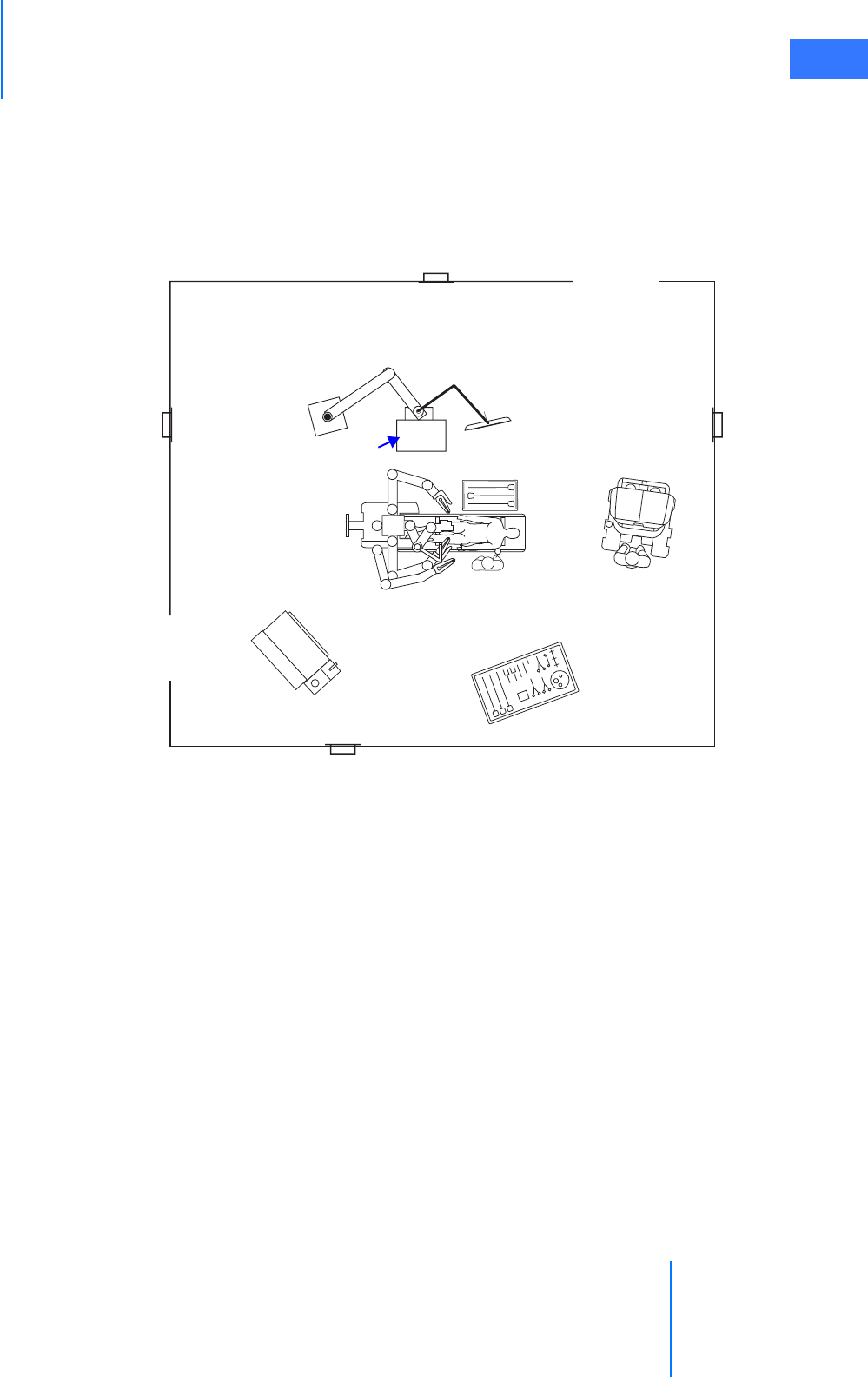
D.6 Boom Positioning
Similar to the positioning of the Vision Cart in relationship to the patient, the vision boom
needs to be positioned to a location that is convenient to the surgical staff to have access to
the equipment. The vision boom positioning also must take into consideration the location of
the third da Vinci instrument arm during the specific procedure performed. The boom must be
placed within reach of the 5.75 m (18’-6”) camera cable attached to the front of the Core.
Figure D.14 Typical boom positioning
_________________________________End of section______________________________
VisionBoom
components
Appendix E: OnSite™ for da Vinci® Surgical System
da Vinci® Si™
E-1
DRAFT/PRE-RELEASE/CONFIDENTIAL
10/9/14
EAppendix E: OnSite™ for da Vinci® Surgical
System
E.1 General Information
The following appendix is applicable only if your da Vinci Si System has da Vinci OnSite
enabled.
Contact Information
For Customer Service and Reporting of Complaints or Adverse Events
Use the following information for customer service, including ordering, reporting complaints
or adverse events, and general information regarding Intuitive Surgical or our products and
services.
For Technical Support
If the system requires maintenance or service, please call our Technical Support line. In the
U.S., call 1-800-876-1310, where phones are staffed 24 hours a day, seven days a week. In
Europe, call +41.21.821.2020.
Manufacturer
General Precautions, Warnings, and Contraindications
Note: All da Vinci Surgical System users must follow all instructions for use supplied with
the system, its components, instruments, and accessories. This includes the following
documents: Instruments and Accessories User Manual (PN 550675), Reprocessing
Instructions (PN 550875), and any instructions for use (IFUs) provided with instruments
or accessories.
WARNING: Be sure to read and understand all information, particularly the caution and
warning information, found in the applicable user manuals before using these products.
Failure to properly follow all instructions, including those in the da Vinci Surgical System
user manual, and instructions supplied with accessory devices such as generators, may
lead to injury and result in improper functioning of the device.
In the U.S.
Intuitive Surgical, Inc.
1266 Kifer Road
Sunnyvale, CA 94086 USA
Toll free: 1.800.876.1310
Direct: 408.523.2100
Fax: 408.523.2377
In Europe:
Intuitive Surgical Sàrl
1, chemin des Mûriers,
1170 Aubonne, Switzerland
Toll free: +800.0821.2020
Direct: +41.21.821.2020
Fax: +41.21.821.2021
Intuitive Surgical, Inc.
1266 Kifer Road
Sunnyvale, CA 94086 USA
www.intuitivesurgical.com
Intuitive Surgical Sàrl
1, chemin des Mûriers,
1170 Aubonne Switzerland
da Vinci® Si™
Appendix E: OnSite™ for da Vinci® Surgical System E-2
DRAFT/PRE-RELEASE/CONFIDENTIAL
10/9/14
CAUTION: OnSite components may be installed and serviced only by Intuitive Surgical
personnel. Do not attempt to install or service equipment without Intuitive Surgical
personnel.
CAUTION: Leakage current from interconnected electrical equipment may exceed safe
levels. To maintain the safety of patients and users, interconnect only with devices in
compliance with IEC 60601-1-1. It is the user’s responsibility to ensure that any
interconnected equipment not supplied by Intuitive Surgical maintains compliance with
IEC 60601-1-1.
CAUTION: Ethernet networks (both wired and wireless) are subject to losses of
connectivity that could disrupt use of OnSite or make data unreliable when it is received
at a remote location. Such disruptions, if they occur, have no effect on the performance
or functionality of the da Vinci Surgical System.
E.2 Indications for Use – OnSite
OnSite for da Vinci Surgical Systems is an accessory indicated for use by trained
Intuitive Surgical Field Service personnel to: (1) obtain system information for the purpose of
diagnosing faults, (2) remotely enable/disable features including configuration updates
through either a wired or wireless Ethernet connection between the da Vinci Surgical System
and the hospital’s Internet Protocol (IP) infrastructure.
E.3 Network Connections
OnSite requires a wired RJ45 Ethernet 10bT/100bT and/or wireless 802.11 network connection
with Internet access where the da Vinci Surgical System will be used.
E.4 Transmitter Module Label
When the optional wireless bridge is installed, the following Federal Communications
Commission (FCC) identification label will be affixed to the Surgeon Console.
Figure 1 Transmitter Module Label
Contains Transmitter Module FCC ID: SWX-NS2

Appendix E: OnSite™ for da Vinci® Surgical System
da Vinci® Si™
E-3
DRAFT/PRE-RELEASE/CONFIDENTIAL
10/9/14
E.5 Introduction
OnSite provides connectivity that enables Intuitive Surgical service personnel to remotely
service the da Vinci Surgical System pre-operatively and intra-operatively. It enables the
following capabilities.
1. Automated log retrieval, where da Vinci Surgical System uploads logs to an Intuitive
Surgical server when idle
2. Remote system status monitoring
3. Remote diagnostics and servicing
4. Remote configuration changes
5. Enable/disable device features
The monitoring capability enables a faster response time from the da Vinci dVSTAT™ (da Vinci
Surgery Technical Assistance Team) for problem resolution, real time diagnosis, and increased
diagnostic accuracy.
To implement remote service capabilities, the da Vinci Surgical System must have access to the
Internet. OnSite is designed to accomplish this using existing hospital networks.
E.6 OnSite System Requirements and Connections
The remote servicing features of OnSite are designed to be highly secure and to function
transparently. The da Vinci Surgical System communicates with an Intuitive Surgical server via
outgoing network connections to enable Intuitive Surgical service personnel to remotely
monitor and service the system while in use.
da Vinci® Si™
Appendix E: OnSite™ for da Vinci® Surgical System E-4
DRAFT/PRE-RELEASE/CONFIDENTIAL
10/9/14
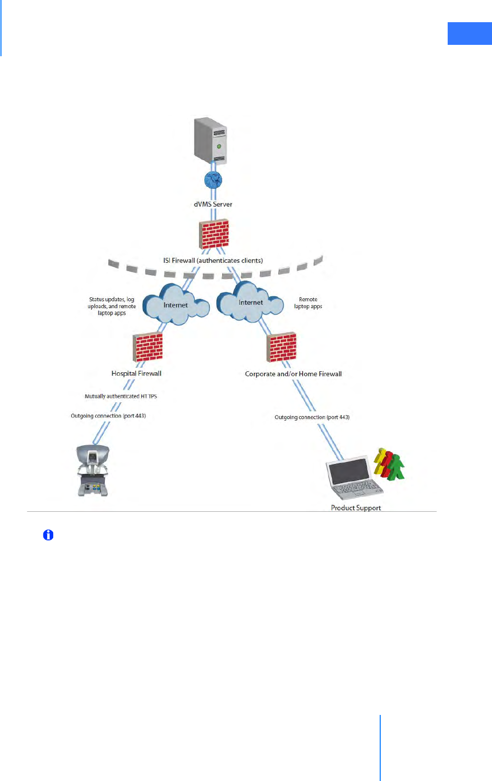
In summary, OnSite consists of three major components, namely the da Vinci Surgical System
with installed networking components, the Intuitive Surgical server, and the remote user
(Intuitive Surgical Field Service personnel). The block diagram below illustrates the OnSite
networking infrastructure.
Figure 2 OnSite Networking Infrastructure
Note: To take advantage of the full potential of OnSite, the system must remain
connected to the network.
Appendix E: OnSite™ for da Vinci® Surgical System
da Vinci® Si™
E-5
DRAFT/PRE-RELEASE/CONFIDENTIAL
10/9/14
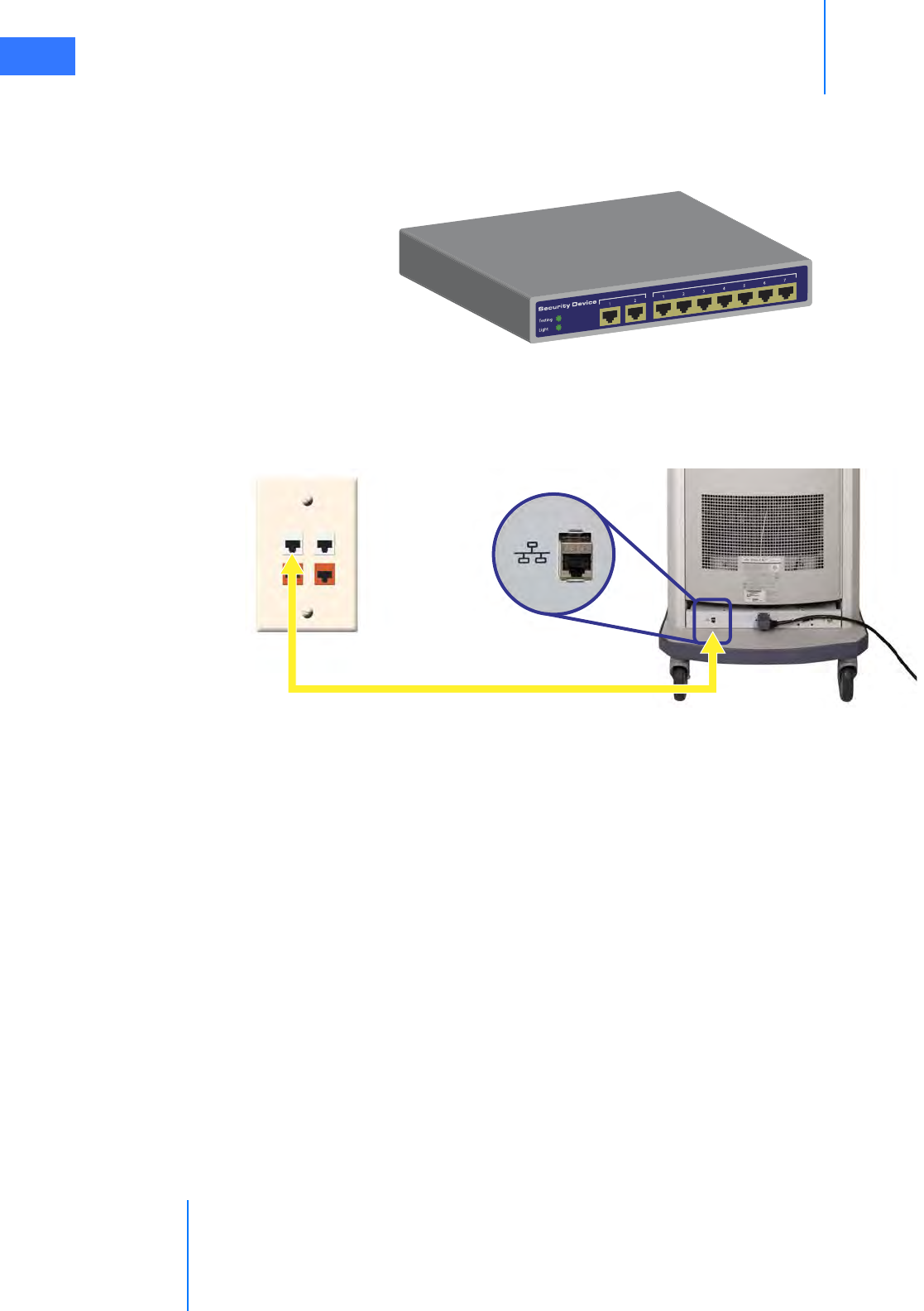
Wired Network Connection
Intuitive Surgical field service personnel install a network security device inside the da Vinci
Surgical System, along with necessary cables and panels to enable a wired network
connection for OnSite.
Figure 3 Network Security Device
To establish a wired connection:
Connect the da Vinci Ethernet connection to the hospital network (wall plate) using a CAT5e
industrial style network cable.
Figure 4 Network Cable Connections (da Vinci Si)
Ethernet to hospital network (wall)
Connects da Vinci System to network
da Vinci® Si™
Appendix E: OnSite™ for da Vinci® Surgical System E-6
DRAFT/PRE-RELEASE/CONFIDENTIAL
10/9/14
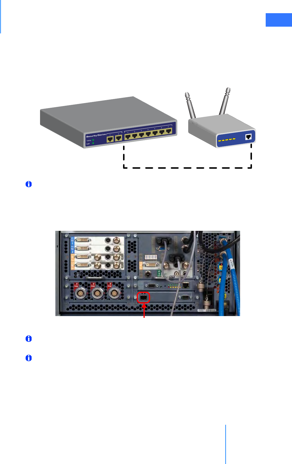
Optional Wireless Connection
There is an optional wireless connection available using the Network Security device and a
Wireless Bridge. See Section E.10 Wireless Connectivity Option and section E.13 OnSite
Appendix C: Wireless Bridge Data for details on wireless connectivity.
Figure 5 Network Security Device with Wireless Bridge
Note: External connections are not required for the da Vinci Si Surgical System.
5.7 Disabling All Network Connectivity
If there is a need to disable all network connectivity for the da Vinci Si System, open the back of
the Vision Cart and disconnect the RJ-45 (Ethernet) connector at bottom center of the Core,
indicated below.
Figure 6 RJ-45 Connector – Core (da Vinci Si)
Note: This action disables all network connectivity for the da Vinci Si System, but it
does not power off the wired or wireless networking equipment.
Note: To re-establish network connectivity, you must re-connect the indicated RJ-45
connector on the back of the Core.
Disconnect to disable networking
Appendix E: OnSite™ for da Vinci® Surgical System
da Vinci® Si™
E-7
DRAFT/PRE-RELEASE/CONFIDENTIAL
10/9/14
E.8 Automatic Status and System Log Retrieval
OnSite provides real-time system status monitoring and post-procedure upload of system
logs, for the support team to service the da Vinci System. When Intuitive Surgical field service
personnel enable the OnSite functionality, the da Vinci Surgical System can:
1. Connect to an Intuitive Surgical server for these purposes:
A. Provide status updates – typically every 10 seconds but can be configured for
different intervals
B. Upload all system logs to the Intuitive Surgical server after each procedure
2. Connect to field service diagnostic applications running on a remote laptop
E.9 OnSite Servicing and Diagnostics
OnSite enables remote servicing using current diagnostic applications that Intuitive Surgical
Field Service personnel normally use when the technician visits on site. When physically
present, the technician troubleshoots the system using a local connection between the laptop
and the da Vinci System hardware. OnSite enables the technician to troubleshoot remotely,
using the same set of diagnostic tools. Through a remote OnSite connection, the technician
can interact with the system in either Normal Mode or Maintenance Mode.
Normal Mode
In Normal Mode, OnSite can only enable remote monitoring of system status. This allows
dVSTAT to passively monitor information transmitted, with no ability to perform any activity
that impacts the movement or performance of the surgical system.
In Normal Mode, dVSTAT can:
• Receive system logs
• Check the condition of system switches and buttons
• Verify surgical instrument functionality.
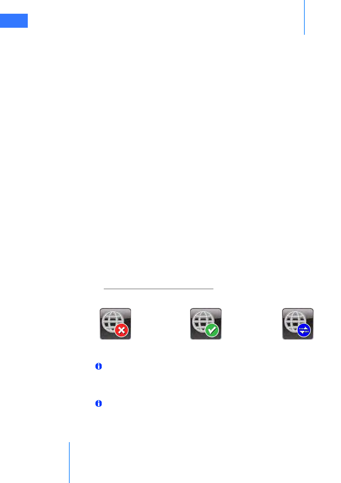
Normal Mode – OnSite Mode Indications
While in Normal Mode, the da Vinci Si System indicates the status of the network connection.
Figure 7 OnSite Connection Status Indicators
Note: Once the Ethernet cable is connected, it can take up to two minutes to detect the
da Vinci network and update the status on the touchscreen.
Maintenance Mode
Note: Intuitive Surgical personnel can use Maintenance Mode only when they request it
and are granted verbal permission by OR staff present with the da Vinci Surgical System.
Maintenance Mode is a state where Intuitive Surgical technical support personnel can connect
remotely to the da Vinci System to perform diagnostic and troubleshooting operations.
da Vinci Network Offline da Vinci Network Online OnSite Session In Progress
da Vinci® Si™
Appendix E: OnSite™ for da Vinci® Surgical System E-8
DRAFT/PRE-RELEASE/CONFIDENTIAL
10/9/14
When in Maintenance Mode, the da Vinci Surgical System is not for human use.
Intuitive Surgical technician requests for this service requires facility staff to place the system in
Maintenance Mode at an agreed-upon time.
Putting the System into Maintenance Mode
To put the system into Standby Mode, make sure the following conditions are met:
• All system components are connected to AC power
• Surgeon Console and Patient Cart system cables are connected to the Core
When the system is in Standby Mode, the power buttons on the Surgeon Console, Vision Cart,
and Patient Cart are lit amber. When an Intuitive technician connects to the system, they have
the option to power on the system in Maintenance Mode.
During an OnSite session in Maintenance Mode, the system displays:
Maintenance Mode - Not for Human Use
Remote Session in Progress
System Servicing/ Diagnostics
An example of an OnSite servicing capability that requires assistance and feedback from
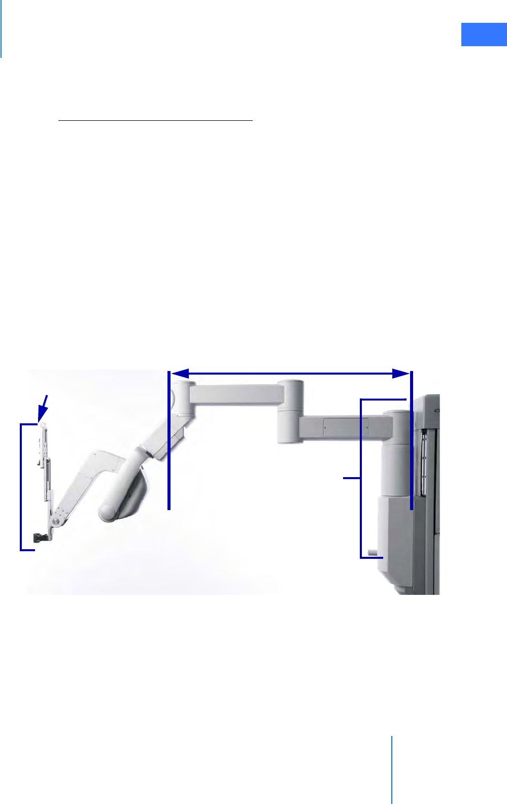
hospital personnel is when remotely testing the control and motion of the manipulators and
robotic arms. Refer to the following illustration.
Figure 8 Setup Joint and Instrument Arm
The following list shows several diagnostic capabilities that an Intuitive Surgical field service
technician can execute remotely when connected in Maintenance Mode via OnSite:
1. Test joints, internal sensors, and positioning potentiometers
2. Check condition of system switches and buttons
3. Check synchronization of system configuration
4. Modify system configurations
5. Perform arm motion and other diagnostic tests
Vertical range
of motion
Setup Joint
Telescoping Axis

Appendix E: OnSite™ for da Vinci® Surgical System
da Vinci® Si™
E-9
DRAFT/PRE-RELEASE/CONFIDENTIAL
10/9/14
6. Verify surgical instrument functionality
7. Check usage hour meter data
E.10 Wireless Connectivity Option
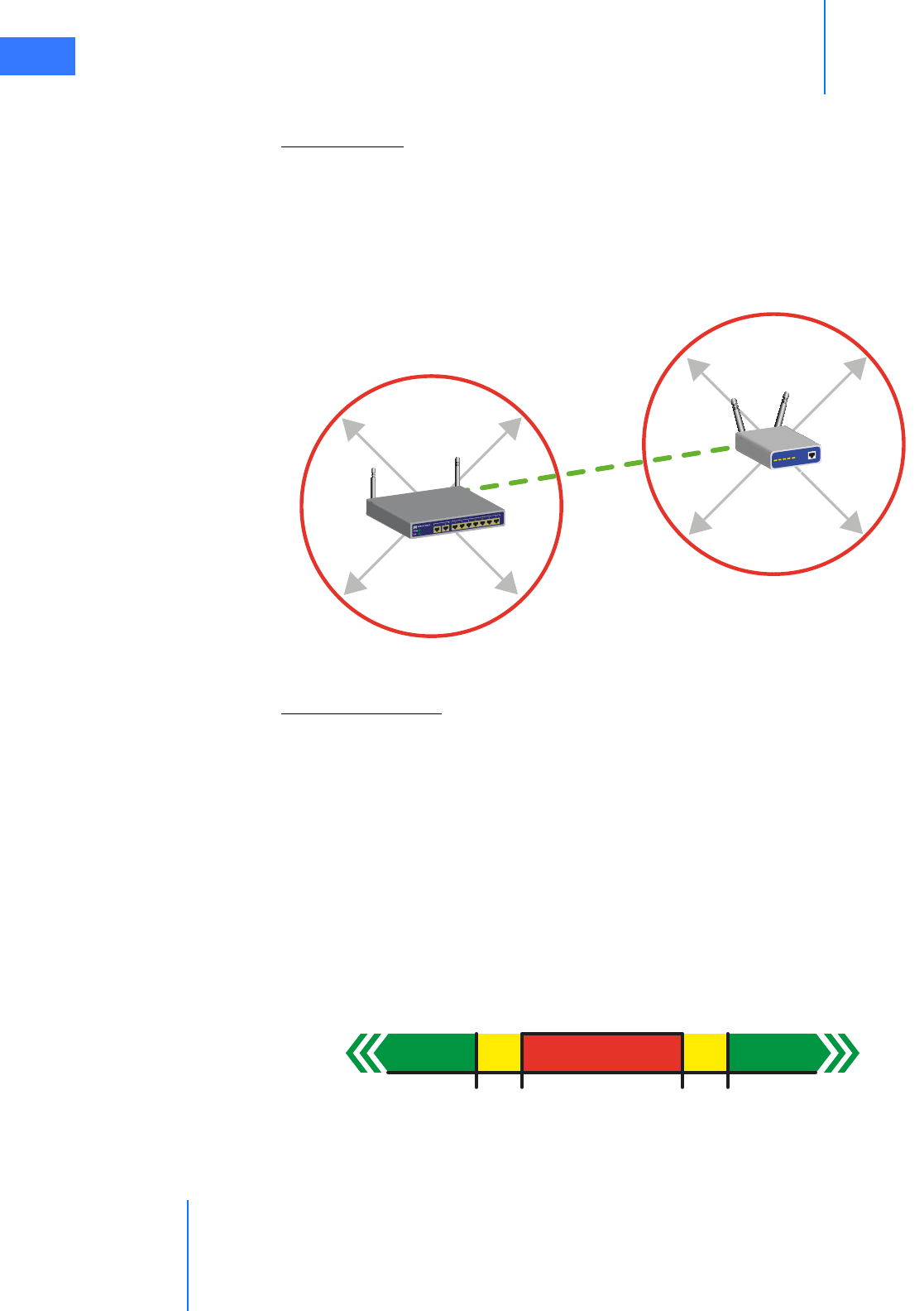
Wireless Overview
A wireless bridge is installed on the da Vinci Surgical System to enable the Wireless
Connectivity Option. A hospital-supplied Wireless Access Point with Internet access is required
to establish wireless connectivity.
Wireless Network Requirements
Intuitive Surgical field service personnel will install and configure the Wireless Connectivity
Option. Below are the details of a suitable wireless network to support da Vinci wireless
applications.
Specifications
• The Wireless Connectivity Option utilizes the IEEE 802.11 wireless standard using either
802.11b or 802.11g at 2.4 GHz Industrial, Scientific, and Medical (ISM) band.
• The Wireless Bridge operates as a client to the hospital-supplied Wireless Access Point,
transmitting data back and forth between the hospital network and da Vinci applications.
• The Wireless Access Point must be located within 75 feet of the da Vinci Surgical System.
Security
• Wireless Network Infrastructure
•Intuitive has tested the Wireless Connectivity Option in WPA2 pre-shared key mode
with AES encryption, and recommends that the Wireless Connectivity Option is
integrated into the hospital network using this security configuration.
•OnSite Software Application
•The OnSite Software Application uses a Secure Socket Layer (SSL) session based on
unique certificates on the da Vinci System and the OnSite server.
• Data being transmitted from the da Vinci Surgical System to the server is 128-bit
encrypted.
Quality of Service
• Wireless Bridge
• Maximum latency of 50 ms between the Wireless Bridge and the hospital-supplied
Wireless Access Point
• Wireless Channel that has 20% or less utilization
•Overall Network
• Maximum end-to-end packet loss of less than 10%
•Network latency should not exceed 300 ms
Once successfully installed and configured, Intuitive Surgical field service personnel conduct
an end-to-end functional test to ensure that OnSite functions as expected.

da Vinci® Si™
Appendix E: OnSite™ for da Vinci® Surgical System E-10
DRAFT/PRE-RELEASE/CONFIDENTIAL
10/9/14
Note: After installation, Intuitive Surgical recommends that the hospital routinely
monitor to ensure that the Wireless Channel does not exceed 20% utilization, and the
latency between the Wireless Access Point and the Wireless Bridge does not exceed 50
ms. If either exceeds the specified levels, contact Intuitive Surgical Technical Support.
It is possible that the wireless network conditions might degrade over time or experience
periods of disturbance; da Vinci applications have been designed to be robust to typical
network disturbances, but if an issue persists, contact Technical Support for assistance to
resolve the issue.
Note: Intuitive Surgical recommends that an active wired port be available when using
the Wireless Connectivity Option. The configuration for the Wireless Connectivity
Option provides a wired backup that the router will automatically activate when
plugged in. Refer to E.11 OnSite Appendix A: IT Requirements for details on how to
establish a wired connection.
Note: It is important to note that if the wireless network is modified or updated after the
Wireless Connectivity Option is installed, its suitability to support the wireless
applications should be re-assessed. In particular, contact Technical Support if any of the
following changes are planned or have occurred.
• If the Wireless Access Point or da Vinci Surgical System is moved from the location where
it resided during installation
• If the Wireless Access Point is replaced with a new make or model
Wireless Coexistence
Wireless coexistence with other devices that transmit in the 2.4 GHz range is a concern since it
can impact the reliability of the wireless link. This section summarizes testing conducted by
Intuitive Surgical in an environment with other wireless devices representative of a typical
Operating Room to demonstrate that the Wireless Connectivity Option functioned as
expected. The test setup represented the worst case da Vinci Surgical System setup, and the
position of the common wireless devices was defined to ensure that they were located near
the Wireless Connectivity Option or the Wireless Access Point, and the path between the
transmitter and receiver for most paired devices passed through the signal path between the
Wireless Connectivity Option and the Wireless Access Point. Testing was conducted with a
wireless network that satisfied the characteristics identified in Wireless Overview, page 9.
The Wireless Access Point used during the testing was the Cisco Aironet 1240AG Series. The
Aironet 1240AG Series was configured to operate as a typical Access Point, and therefore
Wireless Access Points from other vendors should result in the same performance. Note that
the characteristics for a suitable wireless network are summarized in Wireless Overview, and
Intuitive Surgical field service personnel will confirm the wireless network is functioning as
expected after installation. A complete list of the common wireless devices used during the
testing (along with details on position, orientation, and type of data transmission) is
summarized in the table in Common Wireless Devices Tested, page 11.

Appendix E: OnSite™ for da Vinci® Surgical System
da Vinci® Si™
E-11
DRAFT/PRE-RELEASE/CONFIDENTIAL
10/9/14
Note: If different types of wireless devices will be used in the Operating Room, or if the
wireless devices are used in different locations than what is described below, then
Intuitive recommends that performance is tested with the wireless devices active, before
use. If you encounter issues using the Wireless Connectivity Option in the presence of
other wireless devices in the Operating Room, contact Intuitive Surgical Technical
Support.
Note: The wireless coexistence testing conducted by Intuitive does not cover use in the
presence of MRI or diathermy machines. The Wireless Connectivity Option should not be
used in the vicinity of these devices.
Common Wireless Devices Tested
Common Wireless Devices Disturbance Details Test S etup
Wireless Monitor
IOGear Model: GUW2015V (receiver)
GUWA200 (transmitter)
3.1 GHz to 4.8 GHz Certified wireless USB
RF Modulation: QPSK/DCM; Data Rate: 480
Mbps
Transmitter attached to a desktop PC
located 50 inches away from the wireless
bridge, and receiver attached to a
monitor on the boom.
Desktop PC oriented so the transmitter
has clear line of sight to the receiver
attached to the monitor, and PC
streaming 720p video.
Smart Phone/Device 2 iPhone4 (3G and 2.4 GHz wireless)
Samsung (2.4GHz wireless)
One iPhone4 sitting on the arm rest of
the Surgeon Console paired with a
Bluetooth headset with a phone call in
progress. The iPhone is also connected to
the WAP. The second iPhone4 is paired
with the Bluetooth speaker.
Samsung phone in the room 72 inches
away from a paired Bluetooth headset
worn by someone at the patient side.
Laptops with wireless 802.11 b; 2.4 GHz
Two Dell laptops connected to the WAP
on the same channel as the Wireless
Bridge, with one laptop streaming a
video over the network from YouTube.
The laptops are approximately 90 inches
away from the Wireless Bridge.
Wireless keyboard and mouse
Microsoft Wireless Desktop – Keyboard and
Mouse 7000:
2.4 GHz range(2,400 – 2,483.5 MHz) FCC IDs
C3K1345, C3K1142 and C3K1123
Wireless keyboard and mouse interfaced
with one of the desktop computers, and
physically sitting on top of the Vision
Cart, 55 inches apart.
Bluetooth keyboard
Microsoft Bluetooth Mobile Keyboard 6000
2.4 GHz range(2,400 – 2,483.5 MHz) FCC ID
C3K1390
Keyboard interfaced with one of the
desktop computers, and physically sitting
on top of the Vision Cart, 55 inches apart.
Bluetooth headset #1 2.402-2.480 GHz range
Jawbone headset paired with the
iPhone4, worn by the surgeon at the
Surgeon Console and used during the
phone call.

da Vinci® Si™
Appendix E: OnSite™ for da Vinci® Surgical System E-12
DRAFT/PRE-RELEASE/CONFIDENTIAL
10/9/14
Bluetooth headset #2 2.402-2.480 GHz range
Bluetooth headset paired with a
Samsung phone, located on the
operating room bed, 72 inches apart,
with a call active.
Bluetooth Speaker Creative D100 Wireless; FCC ID IBAMF8090
2.402-2.480 GHz range
iPhone4 paired with the Bluetooth
speaker playing music located on the
operating room bed, 72 inches apart.
Cordless Telephone Uniden 2.4 GHz Amplified Cordless Phone
System (Clarity-4205)
Phone base is on the desk, and the phone
is on the other side of the room, with the
base and phone continuously
communicating.
Microwave Oven
MagicChef Model MCD11E3W
Output Frequency 2450 MHz; FCC ID
C5F7NF1AMO100N
In the coexistence test, the microwave
oven is placed in the signal path between
the Wireless Bridge and the WAP, 20 feet
away from the WAP. The Wireless Bridge
and WAP are operating at maximum
distance in this test.
In the isolated test with the microwave
oven, it is placed in the signal path
between the Wireless Bridge and the
WAP at a distance where no impact is
observed, and then the Wireless bridge is
moved closer until the connection is
dropped. Wired connection is then
established.
In both test cases, the microwave oven is
oriented such that the seams in the door
are pointing toward the Wireless Bridge
and the Wireless Access Point.
RFID tags
Reader: TagMaster LR-3 Pro (PN 154400)
2.435 to 2.465 GHz range
ID-Tags: TagMaster S1255 MarkTag and
S1240 MarkTag MeM
2.435 to 2.465 GHz range
RFID was tested by placing the Reader
and the ID-tags on each side of the signal
path, between the Wireless Bridge and
the Wireless Access Point. In the
coexistence test case, the tags and reader
were 30 inches apart. During the isolated
test with the RFID setup, they were 36
inches apart in the worst case
configuration.
Electrosurgical Unit
Covidien (formerly ValleyLab) Force FX
(GSTElectro02)
390 kHz
Located in the Vision Cart, which is
placed as close to the Surgeon Console as
possible.
Common Wireless Devices Disturbance Details Test S etup
Appendix E: OnSite™ for da Vinci® Surgical System
da Vinci® Si™
E-13
DRAFT/PRE-RELEASE/CONFIDENTIAL
10/9/14
Devices Known to Interfere
Microwave Oven
Testing conducted by Intuitive Surgical determined that microwave ovens can disrupt wireless
communication in certain configurations:
•Intuitive Surgical recommends keeping microwave ovens (1000 Watt) at least 25 feet from
the Wireless Bridge or Wireless Access Point, especially if it is located in the signal path.
Higher wattage microwaves should be placed at larger distances.
• If a microwave oven causes interference, use the wired backup to correct the problem.
Figure E.1 Placement boundaries for microwave ovens
RFID Reader (2.4 GHz)
Testing conducted by Intuitive Surgical determined that RFID readers operating in frequency
hopping mode, or configured to operate at a frequency that overlaps the channel being used
by the wireless bridge and the WAP, will cause minor network disturbances.
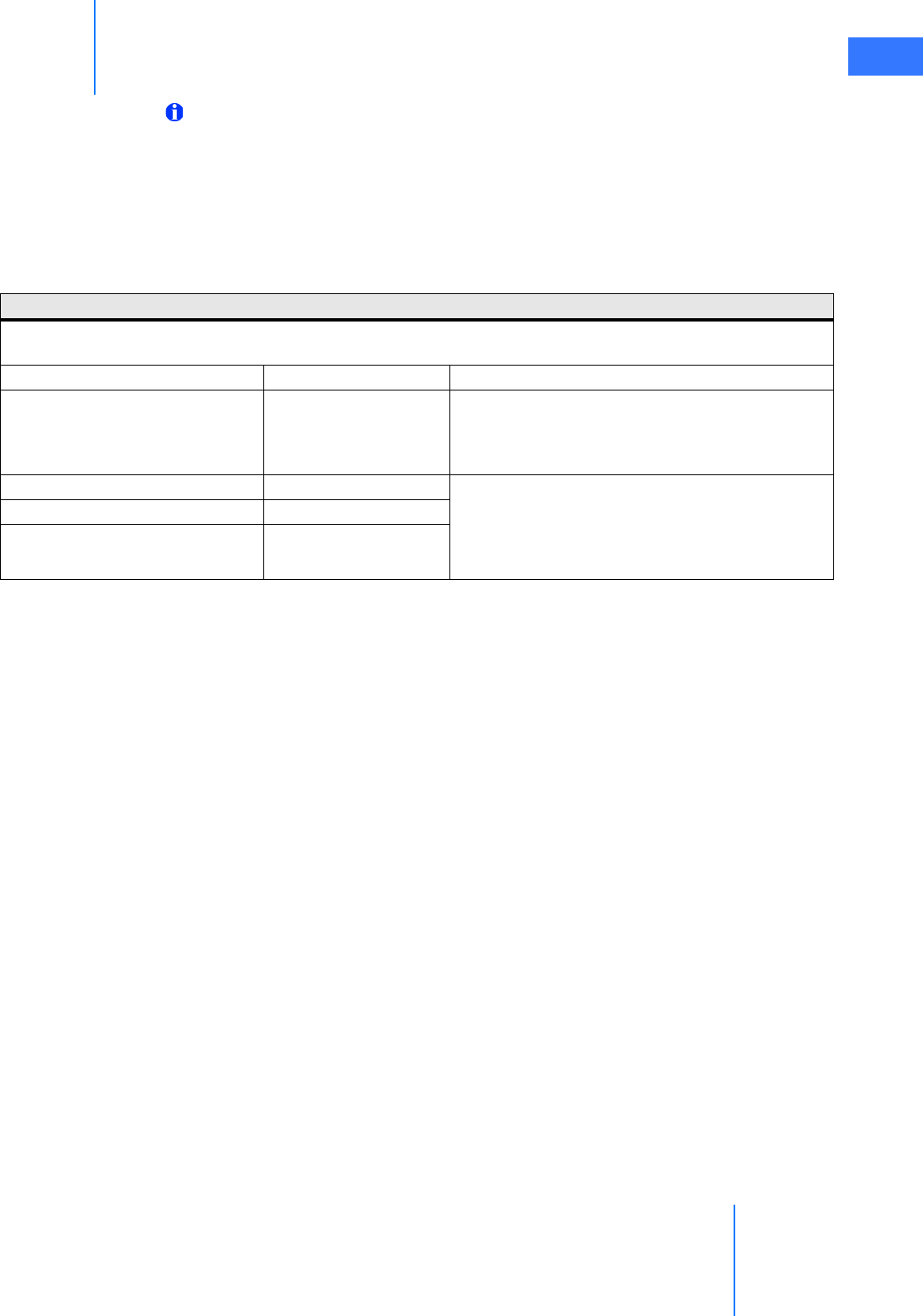
To eliminate the interference, Intuitive Surgical recommends the following:
• The RFID reader not operate in frequency hopping mode if it is being used in the same
room as the Wireless Connectivity Option.
• A separation of a least 4 MHz exists between the frequency range of the channel being
used by the wireless bridge/WAP and the operating frequency of the RFID reader. For
example, a wireless bridge/WAP operating on channel 10 spans 2.446 – 2.468 GHz;
therefore, to avoid disturbances from the RFID reader, its operating frequency should be
less than or equal to 2.442 GHz or greater than or equal to 2.472 GHz.
Figure 6 Valid RFID Reader Operating Frequencies
Wireless Access Point
Wireless Bridge
7.6 meters
or 25 feet
7.6 meters
or 25 feet
Signal
Path
Wireless Connectivity
Option Frequency Range
2.442
GHz
4 MHz
Valid RFID Reader
Operating Frequencies
Valid RFID Reader
Operating Frequencies
4 MHz
2.472
GHz
2.446
GHz
2.468
GHz

da Vinci® Si™
Appendix E: OnSite™ for da Vinci® Surgical System E-14
DRAFT/PRE-RELEASE/CONFIDENTIAL
10/9/14
Note that RFID devices can operate outside the frequency range of what was included in the
testing summarized above. If RFID devices operating outside the range shown above exist in
the operating room, Intuitive Surgical recommends that performance is tested with the RFID
device active, before use.
Addressing Wireless Connectivity Problems
If you encounter connectivity problems while using the Wireless Connectivity Option, Intuitive
recommends you do the following:
• Determine if a device transmitting in the 2.4 GHz range is in the room, and if so, disable
the device to see if it resolves the connectivity problems.
• If you experience several disconnections, and the above step did not resolve the issue, or
if the interfering device must be used, then establish a wired network connection with
the da Vinci Surgical System (see Wired Network Connection for more information).
E.11 OnSite Appendix A: IT Requirements
Internet Access
The network security device that will be integrated into the da Vinci Surgical System requires
Internet access to contact servers at Intuitive Surgical.
Intuitive Surgical requires a wired RJ45 Ethernet 10bT/100bT network drop and/or a wireless
802.11 network with Internet access in the OR where the facility’s da Vinci Surgical System is
used. If your da Vinci Surgical System is used in multiple locations, then Intuitive Surgical
requests that be made available in each location.
OnSite is compatible with both DHCP and static networking addresses.
Proxy Server
OnSite is compatible with most proxy servers. In some instances proxy authentication maybe
required to be by-passed.
Firewall
OnSite requires outbound port 443 open.
Network Topology
OnSite requires a minimum amount of bandwidth to post log files (generally less than 1 MB
per day).

Appendix E: OnSite™ for da Vinci® Surgical System
da Vinci® Si™
E-15
DRAFT/PRE-RELEASE/CONFIDENTIAL
10/9/14
E.12 OnSite Appendix B: Electromagnetic Compatibility
The essential performance for da Vinci Wireless Connectivity during EMC testing was defined
as follows during any of the required tests:
• No component failures
• Video quality exceeded pre-defined metric demonstrating that the video quality was not
impacted
• Audio script test passed demonstrating that the audio link was not impacted
• No changes in programmable parameters
• No resets to factory defaults
• No change in operating mode
• No false alarms
• No initiation of any unintended operation
• No cessation or interruption of any intended operation
Exception: For Voltage Dips and Interrupts, acceptance criteria is no component failures and
is restorable to the pre-test state with operator intervention. For Radiated Immunity in the
band 2.0 - 2.5GHz, acceptance criteria is no component failures and is restorable to the
pre-test state with operator intervention, and restorable during test with a hard-wired
connection.
The da Vinci Surgical System complies with IEC60601-1-2:2001, General Requirements for
safety – Collateral standard: Electromagnetic compatibility. Special precautions and
installation information for the da Vinci Surgical System for electromagnetic compatibility
(EMC) are provided in the following section.
Use only Intuitive Surgical-branded interconnection cables and accessories. Performance of
cables or accessories other than those specified by Intuitive Surgical as replacement parts for
internal components cannot be guaranteed. Any resulting damage to the system will not be
covered under warranty.
Equipment in the operating room, including the da Vinci Surgical System and other portable
or mobile communications equipment, can produce Electromagnetic Interference (EMI),
which may affect the function of these devices. Such effects are prevented by use of
equipment with EMI characteristics proven below recognized limits, as identified in the below
tables.
In the event of suspected interference from other equipment, which prevents the proper
functioning of the da Vinci Surgical System, contact Intuitive Surgical and/or discontinue use of
the system until the problem can be remedied.
The following Tables contain the Manufacturer’s declaration and additional information
required by IEC60601-1-2:2001.
da Vinci® Si™
Appendix E: OnSite™ for da Vinci® Surgical System E-16
DRAFT/PRE-RELEASE/CONFIDENTIAL
10/9/14
Note: This equipment has been tested and found to comply with the limits for a Class A
digital device, pursuant to Part 15 of the FCC Rules. These limits are designed to provide
reasonable protection against harmful interference when the equipment is operated in
a commercial environment. This equipment generates, uses, and can radiate radio
frequency energy and, if not installed and used in accordance with the instruction
manual, may cause harmful interference to radio communications. Operation of this
equipment in a residential area is likely to cause harmful interference in which case the
user will be required to correct the interference at his own expense.
Table 1: Manufacturer’s Declaration – Electromagnetic Emissions
The da Vinci Surgical System is intended for use in the electromagnetic environment specified below. The customer or
the user of the da Vinci Surgical System should assure that it is used in such an environment.
Emissions Test Compliance Electromagnetic Environment – Guidance
RF emissions CISPR 11 Group 1
The da Vinci Surgical System uses RF energy only for its
internal function. Therefore, its RF emissions are very
low and are not likely to cause any interference in
nearby electronic environment.
RF emissions CISPR 11 Class A The da Vinci Surgical System is suitable for use in all
establishments, other than domestic establishments
and those directly connected to the public low-voltage
power supply network that supplies buildings used for
domestic purposes.
Harmonic emissions IEC 61000-3-2 Class A
Voltage fluctuations/ flicker
emissions IEC 61000-3-3 Complies

Appendix E: OnSite™ for da Vinci® Surgical System
da Vinci® Si™
E-17
DRAFT/PRE-RELEASE/CONFIDENTIAL
10/9/14
Table 2: Manufacturer’s Declaration – Electromagnetic Immunity
The da Vinci Surgical System is intended for use in the electromagnetic environment specified below. The customer or
the user of the da Vinci Surgical System should assure that it is used in such an environment.
Immunity Test IEC 60601 Test Level Compliance Level Electromagnetic
Environment Guidance
Electrostatic discharge
(ESD) IEC 61000-4-2 ±6 kV contact ±8 kV air ±6 kV contact ±8 kV air
Floors should be wood,
concrete or ceramic tile. If
floors are covered with
synthetic material, the
relative humidity should be
at least 30%.
Electrical fast
transient/burst IEC
61000-4-4
±2 kV for power supply lines
±1 kV for input/ output lines
±2 kV for power supply lines
±1 kV for input/ output lines
Mains power quality should
be that of a U.S. commercial
or hospital environment with
highly reliable service.
Surge IEC 61000-4-5 ±1 kV differential mode ±2
kV common mode
±1 kV differential mode ±2
kV common mode
Mains power quality should
be that of a U.S. commercial
or hospital environment with
highly reliable service.
Voltage dips, short
interruptions and voltage
variations on power supply
input lines IEC 61000-4-11
<5% UT (>95% dip in UT) for
0.5 cycle 40% UT (60% dip in
UT) for 5 cycles 70% UT (30%
dip in UT) for 25 cycles <5%
UT (>95% dip in UT) for 5 sec.
<5% UT (>95% dip in UT) for
0.5 cycle 40% UT (60% dip in
UT) for 5 cycles 70% UT (30%
dip in UT) for 25 cycles <5%
UT (>95% dip in UT) for 5 sec.
Mains power quality should
be that of a U.S. commercial
or hospital environment with
highly reliable service. If the
user of the da Vinci Surgical
System requires continued
operation during power
mains interruptions, it is
recommended that the da
Vinci Surgical System be
powered from an
uninterruptedly power
supply or a battery.
Power frequency (50/60
Hz) magnetic field IEC
61000-4-8
3 A/m 3 A/m
Power frequency magnetic
fields should be at levels
characteristic of a typical
location in a typical
commercial or hospital
environment.
Note: UT is the AC mains voltage before application of the test level.
da Vinci® Si™
Appendix E: OnSite™ for da Vinci® Surgical System E-18
DRAFT/PRE-RELEASE/CONFIDENTIAL
10/9/14
Table 3: Manufacturer’s Declaration – Electromagnetic Immunity
The da Vinci Surgical System is intended for use in the electromagnetic environment specified below. The customer or
the user of the da Vinci Surgical System should assure that it is used in such an environment.
Immunity test IEC 60601 test
level Compliance level Electromagnetic environment – guidance
Conducted RF IEC
61000-4-6 Radiated
RF IEC 61000-4-3
3 Vrms 150 kHz to
80 MHz
3 V/m 80 MHz to
2.5 GHz
3 Vrms
3V/m
Portable and mobile RF communications equipment
should be used no closer to any part of the da Vinci
Surgical System, including cables, than the
recommended separation distance calculated from the
equation applicable to the frequency of the transmitter.
Recommended separation distance
80 MHz to 800 MHz
800 MHz to 2.5 GHz
where P is the maximum output power rating of the
transmitter in watts (W) according to the transmitter
manufacturer and d is the recommended separation
distance in meters (m). Field strengths from fixed RF
transmitters, as determined by an electromagnetic site
survey,a should be less than the compliance level in
each frequency range.b Interference may occur in the
vicinity of equipment marked with the following
symbol:
Note 1: At 80 MHz and 800 MHz, the higher frequency range applies.
Note 2: These guidelines may not apply in all situations. Electromagnetic propagation is affected by absorption and
reflection from structures, objects, and people.
a. Field strengths from fixed transmitters, such as base stations for radio (cellular/cordless) telephones and land mobile
radios, amateur radio, AM and FM radio broadcast, and TV broadcast cannot be predicted theoretically with accuracy. To
assess the electromagnetic environment due to fixed RF transmitters, an electromagnetic site survey should be
considered. If the measured field strength in the location in which the da Vinci Surgical System is used exceeds the
applicable RF compliance level above, the da Vinci Surgical System should be observed to verify normal operation. If
abnormal performance is observed, additional measures may be necessary, such as re-orientating or relocating the da
Vinci Surgical System.
b. Over the frequency range 150 kHz to 80 MHz, field strengths should be less than 3 V/m.
d1.2P=
d1.2P=
d2.3P=
Appendix E: OnSite™ for da Vinci® Surgical System
da Vinci® Si™
E-19
DRAFT/PRE-RELEASE/CONFIDENTIAL
10/9/14
Table 4: Recommended separation distances between portable and mobile RF
communications equipment and the da Vinci Surgical System
The da Vinci Surgical System is intended for use in an electromagnetic environment in which radiated RF disturbances
are controlled. The customer or the user of the da Vinci Surgical System can help prevent electromagnetic interferences
by maintaining a minimum distance between portable and mobile RF communications equipment (transmitters) and
the da Vinci Surgical System as recommended below, according to the maximum output power of the communications
equipment.
Rated maximum output power
of transmitter W Separation distance according to frequency of transmitter m
150 kHz to 80 MHz 80 MHz to 800 MHz
800 MHz to 2.5 GHz
0.01 0.12 0.12 0.23
0.1 0.38 0.38 0.73
1 1.2 1.2 2.3
10 3.8 3.8 7.3
100 12 12 23
For transmitters rated at a maximum output power not listed above, the recommended separation distance d in meters
(m) can be estimated using the equation applicable to the frequency of the transmitter, where P is the maximum output
power rating of the transmitter in watts (W) according to the transmitter manufacturer.
Note 1: At 80 MHz to 800 MHz, the separation distance for the higher frequency range applies.
Note 2: These guidelines may not apply in all situations. Electromagnetic propagation is affected by absorption and
reflection from structures, objects, and people.
d1.2P=
d1.2P=
d2.3P=
Table 5: Compliance Information
Network Router: CAN/CSA-C22.2 No 60950-1-03
ANSI/UL Std No 60950-1 1st Ed.
Wireless Bridge: *
Wireless Data Rate
802.11b/g: 2.4-2.4835 GHz
802.11b/g: 2.4-2.4835 GHz
* See OnSite Appendix C: Wireless Bridge Data on page 20 for more information
da Vinci® Si™
Appendix E: OnSite™ for da Vinci® Surgical System E-20
DRAFT/PRE-RELEASE/CONFIDENTIAL
10/9/14
E.13 OnSite Appendix C: Wireless Bridge Data
__________________________________End of Section_______________________________
495-499 Montague Expwy. Milpitas, CA 95035 CA 95035 T(408)-942-3085 F (408)-351-4973 http://www.ubnt.com
NS2L DATASHEET
DataRate TX Power Tolerance DataRate Sensitivity Tolerance
1Mbps 20 dBm +/-1dB 1Mbps -95 dBm +/-1dB
2Mbps 20 dBm +/-1dB 2Mbps -94 dBm +/-1dB
5.5Mbps 20 dBm +/-1dB 5.5Mbps -93 dBm +/-1dB
11Mbps 20 dBm +/-1dB 11Mbps -90 dBm +/-1dB
6Mbps 20 dBm +/-1dB 6Mbps -92 dBm +/-1dB
9Mbps 20 dBm +/-1dB 9Mbps -91 dBm +/-1dB
12Mbps 20 dBm +/-1dB 12Mbps -89 dBm +/-1dB
18Mbps 20 dBm +/-1dB 18Mbps -88 dBm +/-1dB
24Mbps 20 dBm +/-1dB 24Mbps -84 dBm +/-1dB
36Mbps 18 dBm +/-1dB 36Mbps -81 dBm +/-1dB
48Mbps 16 dBm +/-1dB 48Mbps -75 dBm +/-1dB
54Mbps 15 dBm +/-1dB 54Mbps -72 dBm +/-1dB
5MHz 10MHZ 20MHz
802.11b
802.11g OFDM
802.11g OFDM
TX SPECIFICATIONS RX SPECIFICATIONS
802.11b
ANTENNA
Outdoor
(
BaseStation Antenna De
p
endent
)
: Over 5km
RANGE PERFORMANCE
ADJUSTABLE CHANNEL SIZE SUPPORT
Wireless A
pp
rovals FCC Part 15.247, IC RS210, CE
RADIO OPERATING FRE
Q
UENCY 2412-2462 MHz
SYSTEM INFORMATION
Processor S
p
ecs Atheros MIPS 4KC, 180MHz
Memor
y
Information 16MB SDRAM, 4MB Flash
Networkin
g
Interface 1 X 10/100 BASE-TX
(
Cat. 5, RJ-45
)
Ethernet Interface
Gain 8dBi
(
2400-2500MHz
)
Surival Wind 216 km /hr
RoHS Com
p
liance YES
REGULATORY / COMPLIANCE INFORMATION
Multi-Polarized 3dB Beamwidth Elevation 60 de
g
rees
Polarization Selection Software Controlled 3dB Beamwidth Azimuth 60 de
g
rees
Polarization
Azimuth Elevation
PHYSICAL / ELECTRICAL / ENVIRONMENTAL
Mountin
g
Kit Pole Mountin
g
Kit included
Enclosure Size 16.3 cm. len
g
th x 3.1 cm. hei
g
ht x 8cm. width
Wei
g
ht 0.18k
g
Enclosure Characteristics Outdoor UV Stabalized Plastic
visit www.ubnt.com/airos
Shock and Vibration ETSI300-019-1.4
Power Method Passive Power over Ethernet
(p
airs 4,5+; 7,8 return
)
O
p
eratin
g
Tem
p
erature -20C to +70C
O
p
eratin
g
Humidit
y
5 to 95% Condensin
g
SOFTWARE
Max Power Consum
p
tion 4 Watts
Power Su
pp
l
y
12V, 1A
(
12 Watts
)
. Su
pp
l
y
and in
j
ector included
Appendix F: 8.5 mm Endoscope for the da Vinci Si System
da Vinci® Si™
F-1
DRAFT/PRE-RELEASE/CONFIDENTIAL
10/9/14
FAppendix F: 8.5 mm Endoscope for the
da Vinci Si System
This section provides details specific to the 8.5 mm 3D endoscope system designed to be used
with the da Vinci Si Surgical System. It augments the information within this manual regarding
endoscopes, especially under Endoscopesin section 7.1 Vision System Overview. Users should
consider the following:
• Users should have a thorough understanding of the use of the 12 mm endoscope system
in conjunction with the da Vinci Si Surgical System before using the 8.5 mm endoscope
and components. This section contains important information about the differences
between the 8.5 mm and 12 mm endoscopes and components.
WARNING: Be sure to read and understand all caution and warning information found
in this manual before using this product.
Indications for Use
The Intuitive Surgical 8.5 mm Endoscopic System is intended for endoscopic viewing of
internal surgery sites during minimally invasive surgery in the peritoneal cavity, thoracic
cavity, and peritoneum. It is designed for use with the Intuitive Surgical da Vinci Si Instrument
Control System during laparoscopic and thoracoscopic surgical procedures.
F.1 Overview
The 8.5 mm endoscope provides a 3D view of the operative field when used with the da Vinci
Si High Definition Vision System. The small diameter of the 8.5 mm endoscope enables the da
Vinci Si Surgical System to be used with a smaller endoscope port. While the system is not
docked, you can use the 8.5 mm endoscope for laparoscopy through a da Vinci 8 mm
instrument cannula.
Figure F.1 Using the 8.5 mm endoscope manually
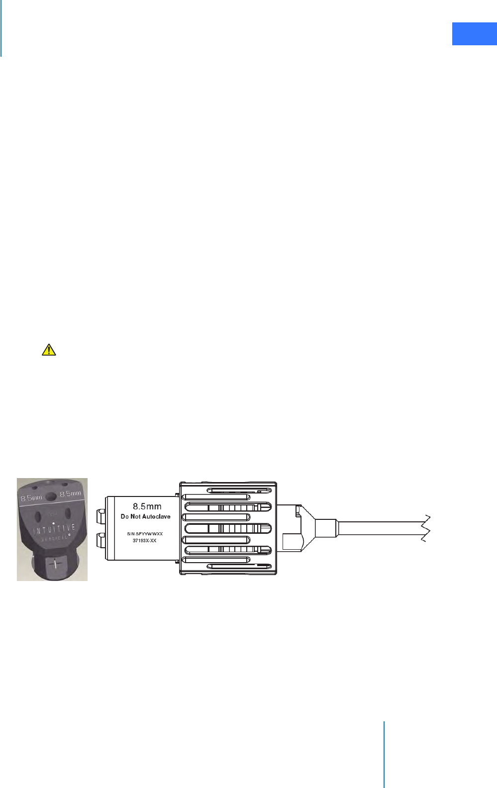
da Vinci® Si™
Appendix F: 8.5 mm Endoscope for the da Vinci Si System F-2
DRAFT/PRE-RELEASE/CONFIDENTIAL
10/9/14
The 8.5 mm endoscope uses a three-piece system concept (endoscope, adapter and camera).
The 8.5 mm endoscope is compatible with the High Definition cameras, illuminators and light
guides provided with the da Vinci Si Surgical System. The 8.5 mm endoscope is available in
straight (0°) and angled (30°) tip configurations.
Special considerations for the 8.5 mm endoscope include:
• While the system is docked, the 8.5 mm endoscope requires use of the 8.5 mm
Endoscope Cannula or a validated third-party endoscope cannula. Refer to the list of
Validated 3rd Party Products for da Vinci® Surgical Systems (PN 871770).
•The 8.5 mm endoscope requires use of the 8.5 mm Alignment Target.
•The 8.5 mm endoscope is approximately 90 mm shorter than the 12 mm endoscope.
•The 8.5 mm endoscope tip is not heated.
•The 8.5 mm endoscope is more flexible than the 12 mm endoscope. Therefore, special
care in the setup and handling of the 8.5 mm endoscope is required.
• To prevent damage during reprocessing, we strongly recommend you place the
endoscope in a properly designed sterilization tray or case, like those we identify in the
list of Suggested 3rd Party Products for da Vinci® Surgical Systems (PN 871771)
•The 8.5 mm endoscope has lower resolution and less brightness than the 12 mm
endoscope.
CAUTION: The 8.5 mm endoscope should only be used in cases where the image quality
of the 12 mm endoscope is not required. A 12 mm endoscope should be available for use
if an increase in image quality is preferred.
F.2 Working with the 8.5 mm Endoscope
The 8.5 mm endoscope uses the same camera arm and camera head drapes as the 12 mm
endoscope. However, the 8.5 mm endoscope requires a specific alignment target and
endoscope cannula. The 8.5 mm endoscope, alignment target and cannulae are clearly
marked “8.5 mm” (see Figure F.2 for examples below).
Figure F.2 “8.5 mm” marking on alignment target and endoscope
The following table provides the compatible combinations of reusable cannula, cannula
mount and alignment target for use with the 8.5 mm endoscope on da Vinci Si Surgical
Systems. For a list of disposable endoscope cannulae validated by Intuitive Surgical, refer to
the list of Validated 3rd Party Products for da Vinci® Surgical Systems (PN 871770).

Appendix F: 8.5 mm Endoscope for the da Vinci Si System
da Vinci® Si™
F-3
DRAFT/PRE-RELEASE/CONFIDENTIAL
10/9/14
Table F-1 Compatible combinations of reusable cannula
Refer to appropriate sections of this user manual for general instructions regarding
endoscope alignment and setup, including connections to the other components of the
Vision System and to the camera arm of the Patient Cart. Refer to the Reprocessing
Instructions for compatible sterilization methods and parameters for the 8.5 mm endoscopes.
________________________________End of section________________________________
Alignment Target Endoscope Cannula Mount Reusable Endoscope Cannula
371679 371521 (ETH/TAUT) 420260
da Vinci® Si™
Appendix G: Symbols, Icons and Text Messages Reference G-1
DRAFT/PRE-RELEASE/CONFIDENTIAL
10/9/14
GAppendix G: Symbols, Icons and Text
Messages Reference
G.1 Overview
This appendix provides a reference for symbols, LEDs (colored lights), icons and text messages
you may see on system components or monitors.
Symbols
Symbols appear on system components and serve these purposes:
• Identification of important system connections and functions
• Provide caution and warning information
LED Status Indicators
Indications of the status of the instrument and camera arms are provided by LEDs on the top
of the insertion axis of each instrument and camera arm. The meanings of the colors are as
follows:
Figure G.1 LED Quick Reference
Corresponding LED icons—graphics that reproduce the LED status—appear simultaneously
on the touchscreen and stereo viewer.
LED Quick Reference
Not ready for surgeon control
blinking
blinking
blinking
Arm or port clutch
Guided tool change
Ready for surgeon control
Warning: Intervention required
See display for details
Error: System restart required
See display for details
System working.
Please wait.
Appendix G: Symbols, Icons and Text Messages Reference
da Vinci® Si™
G-2
DRAFT/PRE-RELEASE/CONFIDENTIAL
10/9/14
On-Screen Icons and Text Messages
Icons and text messages are overlaid on the video displays to provide information regarding
the status of the system. The following figures illustrate arrangement of overlaid elements in
the stereo viewer and touchscreen displays. Note that many overlaid elements appear only
when needed, and others are usually or always present.
Figure G.2 Stereo viewer display (SmartPedal technology)
Critical message
area/icon
Arm 1
status:
on right,
active (larger)
Right master
message area/icon
angle, rotation, zoom Modal message
area
Other console
instrument status area/icon
Camera indicators:
Arm 3
status:
on left
inactive (smaller,
below, gray)
Arm 2
status:
on left,
active (larger)
Left master
message area/icon
Camera arm
message area/icon
name (gray)
Inactive instrument Footswitch map Active instrument
name
Active instrument arm
message areas/icons
Inactive instrument
arm message area/icon
da Vinci® Si™
Appendix G: Symbols, Icons and Text Messages Reference G-3
DRAFT/PRE-RELEASE/CONFIDENTIAL
10/9/14
Figure G.3 Touchscreen display
G.2 Symbols and Icons Reference Table
Arm 2 data:
on left, surgeon
name or console
control
Single or dual console Modal message
area
Critical message
area/icon masters & instruments status
Menu tabs area Camera angle, zoom,
rotation indicator
Camera message
area, icon
Arm 1 data:
on right,
instrument name,
energized (bolt),
foot over enabled
pedal pair (blue)
Instrument arm
message areas,
icons
Menu pop up
area
Table G-1 Symbols and Icons
Symbol or Icon Meaning Where Found
Read the operating instructions. System component labels
Type CF Applied Part On camera head and instruments
Type BF Applied Part On Illuminator.
Note: The da Vinci Si camera
head provides isolation in
accordance with a CF applied part
and is acceptable for use with the
Y1903 Illuminator.
Caution: Hot Illuminator lamp module
or
Appendix G: Symbols, Icons and Text Messages Reference
da Vinci® Si™
G-4
DRAFT/PRE-RELEASE/CONFIDENTIAL
10/9/14
Protective ground Inside (not visible to users) the
Camera Control Unit, Core, Vision
Cart, Patient Cart and Surgeon
Console
Vision Setup button Camera head
Focus In, Focus Out buttons Camera head
Lamp On/Off button Camera head
Flush Port On instruments adjacent to flush
port
30º 30 degrees up, indicates which side
of scope should be on same side as
camera head buttons to achieve
this scope orientation.
On one side of endoscope base
30º 30 degrees down, indicates which
side of scope should be on same
side as camera head buttons to
achieve this scope orientation.
On one side of endoscope base
Turn as indicated to unlock. Camera head and endoscope
Turn as indicated to lock. Camera head and endoscope
Table G-1 Symbols and Icons
Symbol or Icon Meaning Where Found
da Vinci® Si™
Appendix G: Symbols, Icons and Text Messages Reference G-5
DRAFT/PRE-RELEASE/CONFIDENTIAL
10/9/14
Do not autoclave. Endoscope and camera head
Fragile, handle with care Endoscope
Ethernet Connection Inside Surgeon Console service
panel and rear of Patient Cart
Alternating Current On product labels containing rating
information on rear of Patient Cart,
Surgeon Console and Vision Cart
Equipotential Terminal Rear of Surgeon Console, Patient
Cart, Vision Cart, Camera Control
Unit, Illuminator and Core.
Note: The terminal is not
required for operation. It is
provided for convenience to
allow for other equipment to
be at the same equalization
potential as the da Vinci
Surgical System.
Serial Port Connection Inside Surgeon Console service
panel and rear of Patient Cart
Standby—found on Power buttons
of Vision Cart, Patient Cart and
Surgeon Console, lit amber when in
standby mode (connected to mains
but not powered on), blue when
powered on.
Power buttons on Patient Cart,
Vision Cart, Surgeon Console and
Core
Off (power: disconnection from
mains)
Rear of Patient Cart, Vision Cart and
Surgeon Console, Illuminator,
Camera Control Unit and Core
On (power: connection to mains) Rear of Patient Cart, Vision Cart and
Surgeon Console, Illuminator,
Camera Control Unit and Core
DVI DVI video port Back of Core and back of Surgeon
Console
Table G-1 Symbols and Icons
Symbol or Icon Meaning Where Found
Autoclave

Appendix G: Symbols, Icons and Text Messages Reference
da Vinci® Si™
G-6
DRAFT/PRE-RELEASE/CONFIDENTIAL
10/9/14
Composite Composite video ports Back of Core
S-Video S-Video port Back of Core and back of Surgeon
Console
SDI SDI video port Back of Core and back of Surgeon
Console
Audio Audio bay, green Back of Core and back of Surgeon
Console
LLeft Back of Core and back of Surgeon
Console
RRight Back of Core and back of Surgeon
Console
Core
Video
Core Video port Back of Core and back of CCU
Illuminator
Control
Illuminator control ports Back of CCU
Core
Control
Core control ports Back of CCU
Video Control Video control ports Back of Core
Touch
Screen
Audio
Touchscreen audio connection port Back of Core
Touch
Screen
Video
Touchscreen video connection
ports
Back of Core
Touch
Screen
Com
Touchscreen communication ports Back of Core
SERVICE Service connection ports Back of Core
Headset Headset connection port Back of Core and back of Surgeon
Console
Line In Audio line in port Back of Core and back of Surgeon
Console
Line Out Audio line out port Back of Core and back of Surgeon
Console
Video Out
Video out bay, orange, labeled
either “Aux” for auxiliary (on Core);
L (left) and R (right) (on Surgeon
Console); or 1 and 2 (optional bays
on Core)
Back of Core and back of Surgeon
Console
TilePro Input Video in bay, blue Back of Core and back of Surgeon
Console
Table G-1 Symbols and Icons
Symbol or Icon Meaning Where Found
da Vinci® Si™
Appendix G: Symbols, Icons and Text Messages Reference G-7
DRAFT/PRE-RELEASE/CONFIDENTIAL
10/9/14
FIBER Fiber cable (system cable)
receptacle
Next to fiber cable receptacles on
back of Core
BRAKE Indicates the brakes on the Surgeon
Console, applied by stepping down.
Both sides of Surgeon Console, near
floor
PUSH Indicates where to push the
Surgeon Console.
Both sides of Surgeon Console, near
handles
Master clutch Clutch pedal on footswitch panel
Instrument arm swap Arm swap kick-plate (left side) on
footswitch panel
Do not step here. On Patient Cart base
Tip hazard during transport. Stow
touchscreen and close rear door
before moving cart.
On label on rear door of Vision Cart
Do not move Surgeon Console from
the back.
Back of Surgeon Console
Dispose of in accordance with local
regulations—particularly applies to
electronic components.
System labels
Table G-1 Symbols and Icons
Symbol or Icon Meaning Where Found
Appendix G: Symbols, Icons and Text Messages Reference
da Vinci® Si™
G-8
DRAFT/PRE-RELEASE/CONFIDENTIAL
10/9/14
Fiber cable (system cable)
receptacle
Next to system cable receptacles on
back of Core, Surgeon Console and
Patient Cart
Caution: Laser hazard On blue covers of system cable
receptacles on Core, Surgeon
Console and Patient Cart
Video output format of associated
output ports is configurable via the
touchscreen. On Video Settings tab,
select Video Output button.
Back of Core, with connection bays
Energy activation cable connection
port
Back of Core
Video out bay, left video channel;
video has no overlays. This is
component video, made up of Y
(green port), PR (red port) and PB
(blue port). A similar label appears
for the right video channel.
Back of Camera Control Unit (CCU)
Surgeon head-in sensor Surgeon Console viewer
Indicates forward and reverse for
the Patient Cart motor drive
Right tiller handle
Indicates range of speed for the
Patient Cart motor drive
Right tiller handle
Table G-1 Symbols and Icons
Symbol or Icon Meaning Where Found
da Vinci® Si™
Appendix G: Symbols, Icons and Text Messages Reference G-9
DRAFT/PRE-RELEASE/CONFIDENTIAL
10/9/14
Shows use of throttle enable switch Between the tiller handles
Shows use of throttle Between the tiller handles
Explains N=Neutral and D=Drive
positions for the motor drive shift
switches. Includes text, “IF NO
CART POWER, USE NEUTRAL TO
MOVE CART”
Top of Patient Cart motor drive
tiller.
“Sweet Spot” label: Its limits
indicate recommended distance
range of Camera Arm remote center
from Patient Cart tower
Camera Arm setup joint
“Drive” position: Patient Cart drive
motor engaged
Patient Cart base near motor shift
switches
“Neutral” position: Patient Cart
drive motor disengaged
Patient Cart base near motor shift
switches
Brake release Near upper port clutch button on
instrument and camera arms
Table G-1 Symbols and Icons
Symbol or Icon Meaning Where Found
Appendix G: Symbols, Icons and Text Messages Reference
da Vinci® Si™
G-10
DRAFT/PRE-RELEASE/CONFIDENTIAL
10/9/14
Pinch/Crush Hazard On Patient Cart, below upper port
clutch button and at junction of
setup joint and top of column on
instrument and camera arms; on
Surgeon Console
Emergency Power Off Rear of Patient Cart
Interference may occur in the
vicinity of equipment marked with
this symbol.
Not used on IS3000 system but may
appear on other equipment in the
OR
Speaker connection port Back of Core
Microphone connection port Back of Core
The system is preparing to shut
down. A message indicating the
number of seconds until shut down
appears in the body text area.
Critical message area
General information icon. Appears
when the system is providing
information that is not fault-related.
Critical message area
Camera arm message area
General warning / recoverable fault.
Appears when the system detects a
recoverable fault somewhere
within the system not associated
with a particular arm or master.
Critical message area
Touchpad popup dialog
Touchpad error handling area
Table G-1 Symbols and Icons
Symbol or Icon Meaning Where Found
da Vinci® Si™
Appendix G: Symbols, Icons and Text Messages Reference G-11
DRAFT/PRE-RELEASE/CONFIDENTIAL
10/9/14
General critical warning /
non-recoverable fault. Appears
when the system detects a
non-recoverable fault somewhere
within the system not associated
with a particular arm or master.
Critical message area
Touchpad error handling area
Can also appear by itself on the
touchscreen and touchpad when a
critical startup error has occurred
Scope not detected. Appears when
the system does not detect an
endoscope and the user is
attempting to go into following.
Critical message area
Touchpad popup dialog
Guided tool change in progress Instrument arm message area
The system has detected a problem
with the instrument. This can
appear when the instrument is
expired, when the instrument is
incompatible with the system,
when the system is not prepared to
have an instrument installed on it,
or when the system is having
difficulty communicating with the
instrument.
Instrument arm message area
General informational icon related
to the instrument. This can appear
when the system is downloading
new instrument information from a
plug-and-play instrument.
Instrument arm message area
Camera arm is currently clutched
and is free to be moved by OR staff
around its remote center.
Camera arm message area
Table G-1 Symbols and Icons
Symbol or Icon Meaning Where Found
Appendix G: Symbols, Icons and Text Messages Reference
da Vinci® Si™
G-12
DRAFT/PRE-RELEASE/CONFIDENTIAL
10/9/14
Instrument arm is currently
clutched and is free to be moved by
OR staff around its remote center.
Instrument arm message area
The system has detected a
non-recoverable fault on the left
master.
Left master message area
The system has detected a
non-recoverable fault on the right
master.
Right master message area
The system has detected a
non-recoverable fault on an
instrument arm.
Instrument arm message area
The system has detected a
non-recoverable fault on the
camera arm.
Camera arm message area
Move the right master grips to
match the instrument grips (i.e.,
“Follow on matching grip”).
Right master message area
Table G-1 Symbols and Icons
Symbol or Icon Meaning Where Found
da Vinci® Si™
Appendix G: Symbols, Icons and Text Messages Reference G-13
DRAFT/PRE-RELEASE/CONFIDENTIAL
10/9/14
Move the left master grips to match
the instrument grips (i.e., “Follow
on matching grip”).
Left master message area
The system has detected a
recoverable fault or other
resolvable problem on the left
master.
Left master message area
The system has detected a
recoverable fault or other
resolvable problem on the right
master.
Right master message area
The system has detected a
recoverable fault or other
resolvable problem on an
instrument arm.
Instrument arm message area
The system has detected a
recoverable fault or other
resolvable problem on the camera
arm.
In dual console mode, appears
when camera control pedal is
pressed on other console,
explaining why instruments stop
moving and firing.
Camera arm message area
Above footswitch map when
camera control pedal is pressed on
other console.
The instrument tip is still inside the
cannula. To continue, you must
clutch the instrument arm and
advance the tip into the body.
Instrument arm message area
Table G-1 Symbols and Icons
Symbol or Icon Meaning Where Found
Appendix G: Symbols, Icons and Text Messages Reference
da Vinci® Si™
G-14
DRAFT/PRE-RELEASE/CONFIDENTIAL
10/9/14
The system has detected excessive
force on an instrument arm. This
normally means that some external
object is pushing on an arm.
Instrument arm message area
This instrument arm is locked;
unlock it via the touchpad to use.
Instrument arm message area
Hit the arm swap pedal to use the
instrument in question.
Instrument arm message area
The system has detected a problem
with a cannula.
Instrument arm message area
Relax your grip on the left master so
that it can self-align.
Left master message area
Relax your grip on the right master
so that it can self-align
Right master message area
Table G-1 Symbols and Icons
Symbol or Icon Meaning Where Found
da Vinci® Si™
Appendix G: Symbols, Icons and Text Messages Reference G-15
DRAFT/PRE-RELEASE/CONFIDENTIAL
10/9/14
Roll the left master grip to proceed. Left master message area
Roll the right master grip to
proceed.
Right master message area
Your instruments have been
reassigned. Tap ‘Arm Swap’ pedal to
acknowledge and continue.
Critical message area
Touchscreen instrument arm status
area
Dual console instrument status area
(touchpad and touchscreen)
The instrument arm is conducting
its self test.
Instrument arm message area
The camera arm is conducting its
self test.
Camera arm message area
The left master is conducting its self
test.
Left master message area
Table G-1 Symbols and Icons
Symbol or Icon Meaning Where Found
Appendix G: Symbols, Icons and Text Messages Reference
da Vinci® Si™
G-16
DRAFT/PRE-RELEASE/CONFIDENTIAL
10/9/14
The right master is conducting its
self test.
Right master message area
Select the desired motion scaling
level.
Touchpad popup menu
The ergonomic settings are being
adjusted.
Critical message area
Setup arm has been moved
unexpectedly; press one of the port
clutch buttons to continue.
Instrument or camera arm message
area
Energy activation is currently
unavailable.
Energy may be unavailable because
the instrument installed is not an
energy instrument or because no
compatible ESU for the installed
instrument is detected.
Touchscreen instrument arm status
area
3D viewer instrument arm status
area
Energy activation is currently
available.
Touchscreen instrument arm status
area
3D viewer instrument arm status
area
Table G-1 Symbols and Icons
Symbol or Icon Meaning Where Found
da Vinci® Si™
Appendix G: Symbols, Icons and Text Messages Reference G-17
DRAFT/PRE-RELEASE/CONFIDENTIAL
10/9/14
No scope is detected. Touchscreen camera status area
Touchpad central column on main
page (shown vertically)
Scope detected. This icon is
accompanied by 30˚ , 30˚ , or 0˚.
Touchscreen camera status area
Touchpad central column on main
page (shown vertically)
Digital Zoom. This icon is
accompanied by one of the
following zoom levels:
•Wide
•Full
•2x
•4x
Touchscreen camera status area.
Touchpad central column on main
page
Indicates which manipulator is
currently associated with the
surgeon’s right hand.
Touchscreen instrument arm status
area
Touchpad instrument arm status
area
Indicates which manipulator is
currently associated with the
surgeon’s left hand.
Touchscreen instrument arm status
area
Touchpad instrument arm status
area
Indicates TilePro input 1. Button on touchscreen display
Indicates TilePro input 2. Button on touchscreen display
Table G-1 Symbols and Icons
Symbol or Icon Meaning Where Found
Appendix G: Symbols, Icons and Text Messages Reference
da Vinci® Si™
G-18
DRAFT/PRE-RELEASE/CONFIDENTIAL
10/9/14
Camera Button on touchscreen display (for
selecting endoscopic camera view)
Camera control foot pedal
Touchscreen master status area
(shown when Surgeon Console is in
camera control)
Surgeon Console Button on touchscreen display (for
selecting “surgeon’s TilePro view”)
Electronic brightness control (does
not affect Illuminator light output).
Touchscreen and touchpad displays
Increase setting. Touchscreen display buttons; can
be used as an alternative to sliders
Decrease setting. Touchscreen display buttons; can
be used as an alternative to sliders
Close tab menu. Touchscreen display; used to close
the tab menu
Mute microphone. Touchscreen and touchpad
displays; used to mute the local
microphone (touchpad version
mutes the Surgeon Console
microphone and touchscreen
version mutes the Vision Cart
microphone)
Enable microphone. Touchscreen and touchpad
displays; used to enable the local
microphone (touchpad version
enables the Surgeon Console
microphone and touchscreen
version enables the Vision Cart
microphone)
Table G-1 Symbols and Icons
Symbol or Icon Meaning Where Found

da Vinci® Si™
Appendix G: Symbols, Icons and Text Messages Reference G-19
DRAFT/PRE-RELEASE/CONFIDENTIAL
10/9/14
Speaker volume Touchscreen and touchpad
displays; labels the slider that
controls the local speaker volume
Erase telestration marks. Touchscreen display
Instrument arm locked (when on
screen).
Brake applied (when brake pedal is
depressed on Surgeon Console).
Instrument arm message area on
touchscreen.
Touchpad instrument arm lock
button
Above applied brakes on Surgeon
Console
Adjust right. Touchscreen / touchpad displays
for camera calibration
Adjust left. Touchscreen / touchpad displays
for camera calibration
Adjust up. Touchscreen / touchpad displays
for camera calibration
Adjust down. Touchscreen / touchpad displays
for camera calibration
Secondary Energy Pedal 3D viewer footswitch map
Table G-1 Symbols and Icons
Symbol or Icon Meaning Where Found
Appendix G: Symbols, Icons and Text Messages Reference
da Vinci® Si™
G-20
DRAFT/PRE-RELEASE/CONFIDENTIAL
10/9/14
Secondary Energy Pedal (when
pressed)
3D viewer footswitch map
Primary Energy Pedal 3D viewer footswitch map
Primary Energy Pedal (when
pressed)
3D viewer footswitch map
Arm Swap Pedal 3D viewer footswitch map
Arm Swap Pedal (when pressed) 3D viewer footswitch map
Master Clutch Pedal 3D viewer footswitch map
Table G-1 Symbols and Icons
Symbol or Icon Meaning Where Found
da Vinci® Si™
Appendix G: Symbols, Icons and Text Messages Reference G-21
DRAFT/PRE-RELEASE/CONFIDENTIAL
10/9/14
Master Clutch Pedal (when pressed) 3D viewer footswitch map
Camera Control Pedal 3D viewer footswitch map
Camera Control Pedal (when
pressed)
3D viewer footswitch map
Masters status 3D viewer footswitch map
Masters status: left finger clutch
activated
3D viewer footswitch map
Masters status: right finger clutch
activated)
3D viewer footswitch map
Masters status during camera
control: indicates that roll-to-focus
is available
3D viewer footswitch map
Masters status during camera
control, when master roll is causing
camera to focus in the + direction
3D viewer footswitch map
Master controls status during
camera control, when master roll is
causing camera to focus in the –
direction)
3D viewer footswitch map
Table G-1 Symbols and Icons
Symbol or Icon Meaning Where Found
Appendix G: Symbols, Icons and Text Messages Reference
da Vinci® Si™
G-22
DRAFT/PRE-RELEASE/CONFIDENTIAL
10/9/14
Camera rotation indicator 3D viewer (top center)
Touchscreen (lower right)
Camera rotation indicator when
angle is indeterminate; this can
happen when no scope is selected
or when scope is looking straight
up or straight down.
3D viewer (top center)
Touchscreen (lower right)
Left and right master are not
associated with an instrument arm.
Touchscreen masters & instruments
status area (top center)
3D viewer (upper left) in dual
console mode
Left master is associated with an
instrument on arm 2 and right
master is associated with an
instrument on arm 1.
Touchscreen masters & instruments
status area (top center)
3D viewer (upper left) in dual
console mode
Cautery instrument on arm 1 with
right master is not energized for
some reason.
Touchscreen masters & instruments
status area (top center)
3D viewer (upper left) in dual
console mode
Energized instrument on arm 1 with
right master is locked.
Touchscreen masters & instruments
status area (top center)
3D viewer (upper left) in dual
console mode
There is a problem with the cannula
on arm 1 with the right master.
Touchscreen masters & instruments
status area (top center)
3D viewer (upper left) in dual
console mode
The instrument on arm 1 with right
master is experiencing excessive
external force.
Touchscreen masters & instruments
status area (top center)
3D viewer (upper left) in dual
console mode
Table G-1 Symbols and Icons
Symbol or Icon Meaning Where Found
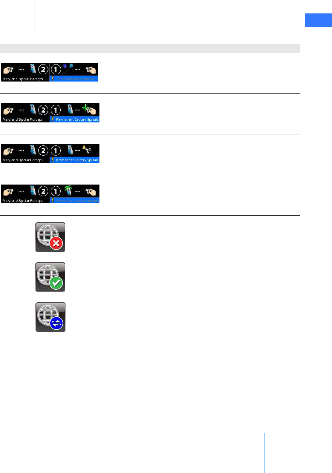
da Vinci® Si™
Appendix G: Symbols, Icons and Text Messages Reference G-23
DRAFT/PRE-RELEASE/CONFIDENTIAL
10/9/14
System reports “No instrument
installed” on instrument arm 1 with
right master.
Touchscreen masters & instruments
status area (top center)
3D viewer (upper left) in dual
console mode
Right master is finger clutched. Touchscreen masters & instruments
status area (top center)
3D viewer (upper left) in dual
console mode
Recoverable problem with right
master.
Touchscreen masters & instruments
status area (top center)
3D viewer (upper left) in dual
console mode
Instrument arm 1 clutched. Touchscreen masters & instruments
status area (top center)
3D viewer (upper left) in dual
console mode
da Vinci Network Offline.Touchscreen lower right
da Vinci Network Online.Touchscreen lower right
OnSite Session In Progress.Touchscreen lower right
Table G-1 Symbols and Icons
Symbol or Icon Meaning Where Found

Appendix G: Symbols, Icons and Text Messages Reference
da Vinci® Si™
G-24
DRAFT/PRE-RELEASE/CONFIDENTIAL
10/9/14
G.3 Text Messages Reference Table
Table G-2 contains a list of text messages that can appear on screen, sorted alphabetically. The
text messages can appear in one or several contexts and locations and are written so as to be
understood in each context on screen, and therefore not explained further. Variables are
shown in italics inside angled brackets, like this: <variable>. This table is provided as a
reference and to support translation into languages not supported in the system software.
Table G-2 Text Messages
Message
# A B C P1 P2 P3 P4 T
<button name> Button Stuck During Self-Test.
<ESU name> is currently connected to your system. Would you like to continue or
disconnect?
<Left master, Right master> switches have been disabled by system. [This is repeated in table
for optional “Left” and “Right” starting letters.]
<Monopolar, Bipolar, etc.> energy disabled; only one <Monopolar, Bipolar, etc.> device is
allowed
<Monopolar, Bipolar, etc.> and <Monopolar, Bipolar, etc.> energy disabled during
simultaneous control
<Surgeon Console, Patient Side> Overlay [This is repeated in table for optional “Surgeon” and
“Patient” starting letters.]
<User name> has connected.
<User name> has disconnected.
<User name> has invited you to join a conference. Would you like to accept?
0
2D
2x
30
3-arm Patient Cart not supported.
Power down, connect 4-arm Patient Cart, and restart.
3D
3D Calibration
3D Viewer Blocked
4-arm Patient Cart not supported.
Power down, connect 3-arm Patient Cart, and restart.
4x
A fault has occurred.
A remote user
Accept
Account Info
Account Management
Adjust as necessary
Adjust the 3D viewer height until it is in a comfortable position.

da Vinci® Si™
Appendix G: Symbols, Icons and Text Messages Reference G-25
DRAFT/PRE-RELEASE/CONFIDENTIAL
10/9/14
Adjust the 3D Viewer tilt until it is in a comfortable position.
Adjust the foot switch panel depth until the controls are easily accessible.
Adjust your chair height to a point at which your legs are at a slight downward angle.
Adjusting Ergonomics
Advance instrument to return to previous location.
Advanced Video Adjustments
Aligning...
Are you sure you want to disable <manipulator name; e.g., Instrument arm 1, camera arm, left
master, etc.>?
Are you sure you want to disable <manipulator name; e.g., left master, instrument arm 2,
camera arm, etc.>?
Are you sure you want to disable the master switches for <left master, right master>?
Are you sure you want to disable the master switches?
Are you sure you want to swap control of all instrument arms?
Are you sure you want to unlock instrument arm <1, 2, or 3>?
Arm clutched at patient cart.
Arm locked.
Arm not ready. Remove instrument to continue.
Arm Stowed
Attention
Audio
Audio Fault - System May Have Reduced or No Audio Feedback
Auto
Auto 3D Calibration
Auto-calibration
Auto-calibration in progress...
Auto Fluorescence Calibration (Part 1)
Auto Fluorescence Calibration (Part 2)
Back
Blue
Both master switches have been disabled by system.
Both surgeon consoles must have same foot tray type.
Brightness
Button Stuck During Self-Test
Calibration
Camera / Scope
Camera / Scope Calibration – Press 'Finish Calibration' to Exit
Camera / Scope Setup
Camera and set-up arm clutched at patient cart.
Table G-2 Text Messages
Message

Appendix G: Symbols, Icons and Text Messages Reference
da Vinci® Si™
G-26
DRAFT/PRE-RELEASE/CONFIDENTIAL
10/9/14
Camera Arm
Camera arm clutched at patient cart.
Camera arm not free to move.
Camera control pedal pressed
Cancel
Canceled
Cannula is invalid, please remove.
Caution: Instrument motion may be non-intuitive
Channel 1 & 2 Configuration
Check video connections. Press 'Recover Fault' to continue.
Check view port for obstructions.
Click 'New User' to create an account.
CLOSE
Close grip to allow cutting.
Clutching
Composite / S-Video / SD-SDI
Conference in Progress
Configure
Confirm
Connect
Connected to Conference
Connection Status
Console
Console <1 or 2>
Contact customer service.
Contact ISI Technical Support for additional information.
Contact ISI Technical Support for assistance.
Contact ISI Technical Support if you require technical assistance.
Continue
Contrast
Control Preferences
Cut complete. Release grip to disable.
Cut is enabled. Press again to cut.
Release grip to disable.
Data Collection in Progress...
da Vinci Network Offline
da Vinci Network Online
Delete Users
Disable
Table G-2 Text Messages
Message

da Vinci® Si™
Appendix G: Symbols, Icons and Text Messages Reference G-27
DRAFT/PRE-RELEASE/CONFIDENTIAL
10/9/14
Disable <name of manipulator; e.g., instrument arm 1, camera arm, right master, etc.> or restart
system to continue.
Disable Arm
Disable Node
Disable Switches
Disconnect
Disconnect one console and reset system to continue.
Disconnect one surgeon console and press 'Recover Fault' to continue.
Disconnect or unpower <ESU name> or <ESU name> to resolve.
[Note: This message appears when two ESUs have conflicting features. Both are listed by
name, so one example would be: “Disconnect or unpower Conmed or ValleyLab to resolve.”]
Display Eye
Display Name is required.
Display name must be unique.
Display Name: <Name>
Display Preferences
Does this calibration look correct?
Done
Don't show this message again
Downloading data, please wait: <#>
Dr. <Name>
Dual Console Mode Not Supported
Dual console not supported.
Power down, disconnect Surgeon Console, and restart.
DVI-D (720p)
DVI-I
DVI-I (1024x768)
DVI-I (1280x1024)
DVI-I (1440x900)
Edge Enhancement
Edit
Edit <user name> Account
Edit User
Emergency Stop Activated
Enable
Endoscopic View
Energy Device Conflict
Ensure the network cable is properly connected.
<ESU name> is currently connected to your system. Would you like to continue or
disconnect?
Table G-2 Text Messages
Message

Appendix G: Symbols, Icons and Text Messages Reference
da Vinci® Si™
G-28
DRAFT/PRE-RELEASE/CONFIDENTIAL
10/9/14
Event Logs
Excessive force detected. Examine arm.
Experimental instrument – Not for human use
Experimental scope – Not for human use
Exit
Failed
Failed: Not white
Failed: Possible dirty scope
Failed: Scope may be damaged
Failed self-check. Remove instrument.
Failed: Target not found
Failed: Too bright
Failed: Too dim
Far
Fault Code: <#####>
Fiber cable connectors require cleaning.
Fiber optic connectors require cleaning.
Fine (3:1)
Finger Clutch
Finish assigning masters at touchpad and press 'OK' to continue.
Finish Calibration
First Name is required.
First Name: <Name>
Fluorescence
Fluorescence
Calibration (Part 1)
Fluorescence
Calibration (Part 2)
Fluorescence Finger Switch
Focusing...
Foot position sensors blocked. Check for obstructions.
Foot position sensors have been disabled by the system.
Footswitch
Format
Full
Give
Graphics
Haptic Zoom
HD-SDI (1080i)
Table G-2 Text Messages
Message

da Vinci® Si™
Appendix G: Symbols, Icons and Text Messages Reference G-29
DRAFT/PRE-RELEASE/CONFIDENTIAL
10/9/14
HD-SDI (720p)
Illuminator
Illuminator bulb expired; Power down system and replace when possible.
Illuminator door is open. Close door and press 'Recover Fault' to continue.
Illuminator lamp module error: Please reseat or replace lamp module
Image Depth
Image Enhancement
Image Quality
Information displayed in 3D viewer
In progress.
Incoming Call
Independent
Insertion axis not free to move. Check for obstructions.
Instrument and set-up arm clutched at patient cart.
Instrument arm <1,2, or 3> is currently associated with a master on the other console. Are you
sure you want to take control of it?
Instrument Arm 1
Instrument Arm 2
Instrument Arm 3
Instrument arm not free to move.
Instrument is expired. Remove.
Instrument not compatible with cannula, please resolve.
Instrument not fully connected. Check all cable connections.
Instrument not fully connected. Check all cable connections and re-install instrument.
Instrument not recognized. Remove and reinstall.
Instrument not supported. Remove.
Instrument tip in cannula; clutch and advance.
Instrument too long for cannula. Remove instrument.
Instrument will expire after procedure.
Instruments Reassigned
Insufficient Battery Charge
Interface Options
Invalid Instrument Installed
Inventory Management
Invited to Conference
L
Large
Last Name is required.
Last Name: <Name>
Table G-2 Text Messages
Message

Appendix G: Symbols, Icons and Text Messages Reference
da Vinci® Si™
G-30
DRAFT/PRE-RELEASE/CONFIDENTIAL
10/9/14
Left Master
<Left master, Right master> switches have been disabled by system. [This is repeated in table
for optional “Left” and “Right” starting letters.]
Left video lost. Check video connections and power.
Lock
Login
Logout
Maintenance Mode – Not for human use
Maintenance Mode – Not for human use (Console 1)
Maintenance Mode – Not for human use (Console 2)
Manage Users
Manual
Master Associations
Master Associations Incomplete
Master Controller Assignments Incomplete
Master not free to move.
Master Scaling
Master Switch Error
Maximum of two arms per side.
Move master grip to match instrument.
Networking hardware fault. OnSite and Connect functionality no longer available. Press
'Recover Fault' to continue.
Network Detected
Network Unavailable
New User
New User (Step <step number> of <total number of steps>)
Next
Next Log
No
No battery backup.
No battery backup. Contact customer service.
No cannula detected. Remove instrument and check cannula.
No Instrument Installed
No Scope Detected
No user logged in.
No video signal. Check video connections and power.
Non-recoverable Fault
Non-recoverable Fault <fault number> Restart system to continue.
Non-recoverable Subsystem Fault
Table G-2 Text Messages
Message

da Vinci® Si™
Appendix G: Symbols, Icons and Text Messages Reference G-31
DRAFT/PRE-RELEASE/CONFIDENTIAL
10/9/14
Non-recoverable Subsystem Fault <fault number>
Non-recoverable Subsystem Fault <fault number>. Disable arm or restart system to continue.
Normal
Normal (2:1)
Not available
Not connected to Vision Cart.
Off
OK
On
OnSite Session in Progress
Page Down
Page Up
Patient cart and surgeon console either not connected or not powered.
Patient cart battery is charging. Please wait.
Patient Cart Disconnected
Patient cart either not connected or not powered.
Patient cart running on battery. Check AC power.
Patient-Side
Patient-Side Touchscreen Failed Self-Test
<Surgeon Console, Patient Side> Overlay [This is repeated in table for optional “Surgeon” and
“Patient” starting letters.]
Pedal Conflict.
Remove conflicting instrument to enable.
Pending
Please wait. Self-test in progress
Preparing to Shut Down
Press and Hold to Restore Settings
Press 'Arm Swap' pedal to activate arm.
Press 'OK' to continue
Press 'Recover Fault' or disable <name of manipulator; e.g., instrument arm 1, right master, etc.>
to continue
Press 'Recover Fault' or 'Disable Switches' to continue.
Press 'Recover Fault' to continue
Press 'Recover Fault' to continue. Contact customer service.
Preventive maintenance recommended. Contact customer service.
Previous Log
Quick (1.5:1)
R
Recover
Recover Fault
Table G-2 Text Messages
Message

Appendix G: Symbols, Icons and Text Messages Reference
da Vinci® Si™
G-32
DRAFT/PRE-RELEASE/CONFIDENTIAL
10/9/14
Recoverable Fault
Recoverable Fault <fault number> Press 'Recover Fault' to continue
Red
Reject
Relax hold on master so it can self-align.
Remote Session in Progress
Remove Instrument
Restart system to continue.
Restart system to continue. Contact customer service.
Restore Factory Settings
Restore Settings
Reverse
<Left master, Right master> switches have been disabled by system. [This is repeated in table
for optional “Left” and “Right” starting letters.]
Right Master
Right video lost. Check video connections and power.
Roll master grip.
Rotate master to match instrument.
Scaling
Scope
Scope Angle
Select a motion scaling level.
Select a scope
Select a zoom level
Select scope angle to continue.
Service recommended. Contact customer service.
Session Available
Session Enabled
Session Ended
Session in Progress
Session Unavailable
Set-up arm clutched at patient cart.
Set-up arm moved unexpectedly. Press port clutch button to clear.
Shutting down in <#> seconds. Press power button to cancel.
Silence
Silence Alarm
Size
Skip Login
Slide to unlock
Table G-2 Text Messages
Message

da Vinci® Si™
Appendix G: Symbols, Icons and Text Messages Reference G-33
DRAFT/PRE-RELEASE/CONFIDENTIAL
10/9/14
Small
Some ergonomic adjustments are unavailable.
Start Calibration
Step <step number> of <total number of steps>: Press the center of the cursor.
Stereo Pair
Successful
Surgeon Console
Surgeon console either not connected or not powered.
<Surgeon Console, Patient Side> Overlay [This is repeated in table for optional “Surgeon” and
“Patient” starting letters.]
Surgeon Console Touchpad Is Not Functional
Surgeon monitor tilt sensor error.
Swap All
Switch Error
System communication failure. Restart system to continue.
System Diagnostic Mode – Not for human use.
System is overheating. Ensure adequate ventilation.
System overheating. Shutting down in <#> seconds. Restart not possible; contact customer
service.
System shutting down.
Take
Telestration Eye
Test was run. Restart system for normal use.
TFO Mode – Not for human use.
the other console's left master
the other console's right master
TilePro
TilePro QuickClick
Touchscreen Calibration: <step number>/<total number of steps>
Touchscreen is not available, but other system functions are unaffected. Press 'Recover Fault'
to continue.
Training instrument – Not for human use
Training scope – Not for human use
Trial Software – Not for human use
Troubleshooting
Unknown
Unlock
Unsupported Parts Installed on System
Use the da Vinci ergonomic controls on the left side pod to adjust the arm rest until your
arms can rest comfortably with your shoulders relaxed.
Table G-2 Text Messages
Message

Appendix G: Symbols, Icons and Text Messages Reference
da Vinci® Si™
G-34
DRAFT/PRE-RELEASE/CONFIDENTIAL
10/9/14
_________________________________End of section______________________________
Utilities
Verify 3D Calibration
Video
Video Fault: Ensure auxiliary video device is powered, then clear fault. If necessary, restart da
Vinci system.
Video Output
Video Settings
Video Source
Video Sync Error
Video System Not Ready
Viewer Mode
Visualization
Warning: Ensure proper scope selection (0 degree scope selected).
Warning: Ensure proper scope selection (30 degree down scope selected).
Warning: Ensure proper scope selection (30 degree up scope selected).
Warning: Ensure proper scope selection (No Scope selected).
Warning: No scope detected. Ensure proper scope selection.
Warning: Patient cart is able to move
White Balance
White balance failed.
White balance failed: image not close enough to white.
White balance failed: image too bright.
White balance failed: image too dim.
White balance failed: possible dirty scope.
White balance in progress.
White balance successful.
Wide
Working Distance
Would you like to connect?
Would you like to connect to a conference?
Would you like to continue?
Yellow
Yes
You are about to reassign instruments in use at the other console. Are you sure?
You are the only member of this conference. Would you like to continue waiting?
Your instruments have been reassigned. Tap ‘Arm Swap’ pedal to acknowledge and continue.
Zoom
Table G-2 Text Messages
Message
da Vinci® Si™
Appendix H: System Specifications H-1
DRAFT/PRE-RELEASE/CONFIDENTIAL
10/9/14
HAppendix H: System Specifications
H.1 Power Specifications
H.2 Physical Dimensions
H.3 Environmental Specifications
See specifications listed on page 1-7.
H.4 Crate Dimensions
Surgeon Console Patient Cart Vision Cart
Voltage
100/120/230 VAC
50/60Hz
Auto Sense
100/120/230 VAC
50/60Hz
Auto Sense
100/120/230 VAC
50/60Hz
Auto Sense
Rating and Typical Current
1000VA Continuous
8.4A at 115V~
4.2A at 230V~
1000VA Continuous
8.4A at 115V~
4.2A at 230V~
1500VA Continuous
12A at 115V~
6A at 230V~
Backup Power NA 5 min NA
Surge Protected Yes Yes No
Surgeon Console Patient Cart Vision Cart
Height 70 in. (178 cm) 69 in. (175 cm) 76 in. (193cm) with
touchscreen stowed
Width 38 in. (97 cm) 36 in. (91 cm) 26.6 in. (67.6cm)
Depth 34 in. (86 cm) 50 in. (127 cm) 36.5 in. (92.7cm)
Weight ~580 lbs. (264 kg) ~1200 lbs. (544 kg) 446 lbs. (202.3kg)
Ground Clearance 1.9 in. (48 mm) 1.9 in. (48 mm) 4 in. (10.2cm)
L x W x H Weight
Surgeon Console 47.5" x 48" x 65.5”
(1.21m x 1.22m x 1.66m)
793 lbs (360 kg)
Patient Cart 67.3” x 47.3” x 77.3”
(1.71m x 1.20m x 1.96m)
1540 lbs (698.5 kg)
Vision Cart 44" x 43" x 83”
(1.12m x 1.09m x 2.11m)
720 lbs (326.6 kg)
Appendix H: System Specifications
da Vinci® Si™
H-2
DRAFT/PRE-RELEASE/CONFIDENTIAL
10/9/14
H.5 Video Patch Panels
Figure H.1 Video and audio connections (back of Core)
Note: One video output is standard. Optional upgrades can provide up to two additional
video outputs.
Selecting Core Video Output
To select the video output format used at each output bay, from the touchscreen, touch Video
Output on the Video Settings tab, which gives access to the following user interface.
Figure H.2 Example of video output option selections
The software buttons on this screen correspond to the applicable Video Out connector bay as
explained below in Table H-1 Video Output Connections – Core.
Core Video Connections
TilePro Input
Video Out bay 1
Video Out bay 2 Video Out bay Aux
Audio In/Out
TilePro Input
Optional
Table H-1 Video Output Connections – Core
Connector
Label
Connector
Type
Software
Button(s)
Output
Format Resolution
DVI DVI-I DVI
(analog and digital)
Automatically configureda
DVI
(digital)
720p (720 x 1280 x
59.94Hz)
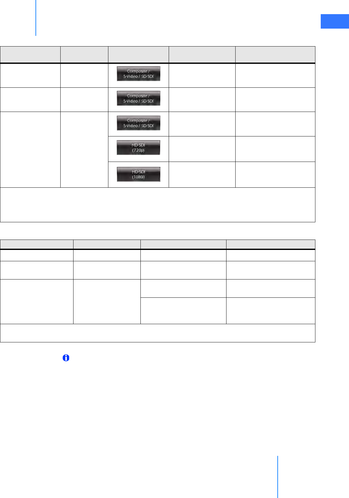
da Vinci® Si™
Appendix H: System Specifications H-3
DRAFT/PRE-RELEASE/CONFIDENTIAL
10/9/14
Note: Each input and output bay supports only one video format at a time.
Composite BNC
Composite (analog)
NTSC (720 x 486 x 29.97Hz)
or PAL (720 x 576 x 25Hz)b
S-Video 4-pin mini-DIN
S-Video (analog)
NTSC (720 x 486 x 29.97Hz)
or PAL (720 x 576 x 25Hz)b
SDI BNC
SD-SDI (digital)
NTSC (720 x 486 x 29.97Hz)
or PAL (720 x 576 x 25Hz)b
HD-SDI (digital)
720p (720 x 1280 x
59.94Hz)
HD-SDI (digital)
1080i (1920 x 1080 x
29.97Hz)
a. Automatically configured video format supports XGA, SXGA, WXGA-Plus analog and digital; 720p
digital only. Not all DVI receiving devices support automatic configuration. To assure format 720p
video output, select the DVI-D (720p) button instead.
b. NTSC or PAL is determined by country.
Table H-1 Video Output Connections – Core
Connector
Label
Connector
Type
Software
Button(s)
Output
Format Resolution
Table H-2 Video Input Connections – Core
Connector Label Connector Type Input Format Resolution
DVI DVI-I DVI (analog and digital) Automatically configureda
S-Video 4-pin mini-DIN S-Video (analog) NTSC (720 x 486 x 29.97Hz)
and PAL (720 x 576 x 25Hz)
SDI BNC SDI (digital) NTSC (720 x 486 x 29.97Hz)
and PAL (720 x 576 x 25Hz)
HD-SDI (digital)
1080i (1920 x 1080 x 29.97Hz)
and 720p (720 x 1280 x
59.94Hz)
a. Automatically configured video format supports XGA, SXGA, WXGA-Plus analog and digital; 720p
digital only.
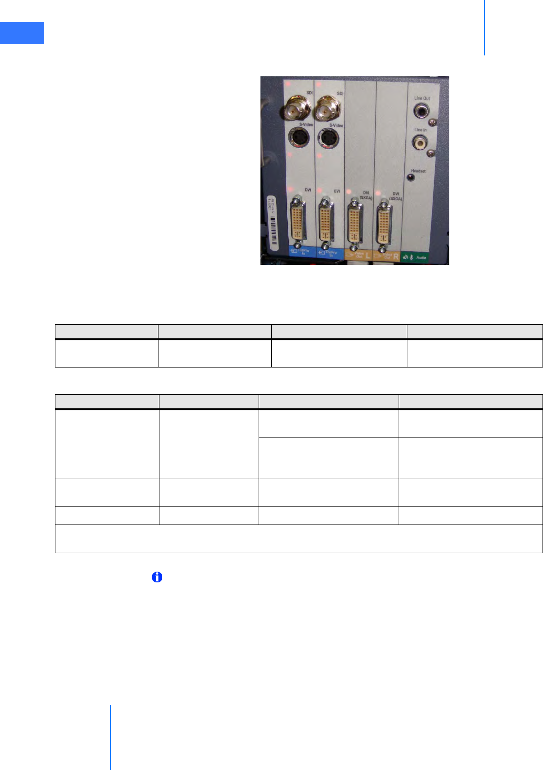
Appendix H: System Specifications
da Vinci® Si™
H-4
DRAFT/PRE-RELEASE/CONFIDENTIAL
10/9/14
Surgeon Console Video Connections
Figure H.3 Connections on back of Surgeon Console
Note: Each input and output bay supports only one video format at a time.
TilePro Inputs Video Out L, R Audio
Table H-3 Video Output Connections – Surgeon Console
Connector Label Connector Type Output Format Resolution
DVI
(SXGA)
DVI-I DVI (analog and digital) SXGA
Table 9: Video Input Connections – Surgeon Console
Connector Label Connector Type Input Format Resolution
SDI BNC SDI (digital) NTSC (720 x 486 x 29.97Hz)
and PAL (720 x 576 x 25Hz)
HD-SDI (digital)
1080i (1920 x 1080 x 29.97Hz)
and 720p (720 x 1280 x
59.94Hz)
S-Video 4-pin mini-DIN S-Video (analog) NTSC (720 x 486 x 29.97Hz)
and PAL (720 x 576 x 25Hz)
DVI DVI-I DVI (analog and digital) Automatically configureda
a. Automatically configured video format supports XGA, SXGA, WXGA-Plus analog and digital; 720p
digital only.
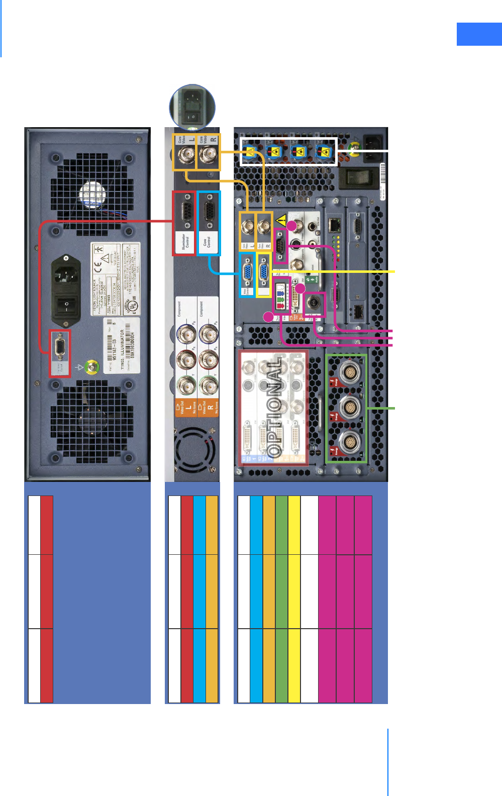
da Vinci® Si™
Appendix H: System Specifications H-5
DRAFT/PRE-RELEASE/CONFIDENTIAL
10/9/14
Core Connections Diagram
_________________________________End of section______________________________
O
O
O
O
O
O
O
O
O
O
O
O
O
O
O
O
O
O
O
O
O
O
O
O
O
O
O
O
O
O
O
O
O
O
O
O
O
O
O
O
O
O
O
O
O
O
O
O
O
O
O
O
O
O
O
O
O
O
O
O
O
O
O
O
O
O
O
O
O
O
O
O
O
O
O
O
O
O
O
P
P
P
P
P
P
P
P
P
P
P
P
P
P
P
P
P
P
P
P
P
P
P
P
P
P
P
P
P
P
P
P
P
P
P
P
P
P
P
P
P
P
P
P
P
P
P
P
P
P
P
P
P
P
P
P
P
P
P
P
P
P
P
P
T
T
T
T
T
T
T
T
T
T
T
T
T
T
T
T
T
T
T
T
T
T
T
T
T
T
T
T
T
T
T
T
T
T
T
T
T
T
T
T
T
T
T
T
T
T
T
T
T
T
T
T
T
T
T
T
T
T
I
I
I
I
I
I
I
I
I
I
I
I
I
O
O
O
O
O
O
O
O
O
O
O
O
O
O
O
O
O
O
O
O
O
O
O
O
O
O
O
O
O
O
O
O
O
O
O
O
O
O
O
O
O
O
O
O
O
N
N
N
N
N
N
N
N
N
N
N
N
N
N
N
N
N
N
N
N
N
N
N
N
N
N
N
N
N
N
N
N
N
N
A
A
A
A
A
A
A
A
A
A
A
A
A
A
A
A
A
A
A
A
A
A
A
A
A
A
A
A
A
A
A
A
A
A
A
A
A
A
A
A
A
A
A
A
A
A
A
A
A
O
O
O
O
O
O
O
O
O
O
O
O
O
O
O
O
O
O
O
O
O
O
O
O
O
O
O
O
O
O
O
O
O
O
O
O
O
O
O
O
O
O
O
O
O
O
O
O
O
O
O
O
O
O
O
O
O
O
O
O
O
O
O
O
O
O
O
O
O
O
O
O
O
O
O
O
O
P
P
P
P
P
P
P
P
P
P
P
P
P
P
P
P
P
P
P
P
P
P
P
P
P
P
P
P
P
P
P
P
P
P
P
P
P
P
P
P
P
P
P
P
P
P
P
P
P
P
P
P
P
P
P
P
P
T
T
T
T
T
T
T
T
T
T
T
T
T
T
T
T
T
T
T
T
T
T
T
T
T
T
T
T
T
T
T
T
T
T
T
T
T
T
T
I
I
I
I
I
I
I
I
I
I
I
I
I
I
I
I
I
I
I
I
I
O
O
O
O
O
O
O
O
O
O
O
O
O
O
O
O
O
O
O
O
O
O
O
O
O
O
O
O
O
O
O
O
O
O
O
O
O
O
O
O
O
O
O
O
O
O
O
N
N
N
N
N
N
N
N
N
N
N
N
N
N
N
N
N
N
N
N
N
N
N
N
N
N
N
N
N
N
N
N
N
N
N
N
N
N
N
N
A
A
A
A
A
A
A
A
A
A
A
A
A
A
A
A
A
A
A
A
A
A
A
A
A
A
A
A
A
A
A
A
A
A
A
A
A
A
A
A
A
A
A
A
A
A
A
A
A
A
A
L
L
L
L
L
L
L
L
L
L
L
L
L
L
L
L
L
L
L
L
L
L
L
L
L
L
L
L
L
L
L
L
L
L
L
L
L
L
L
L
L
L
L
L
L
L
L
L
L
L
L
L
L
L
L
L
L
L
L
L
L
L
L
L
L
L
L
L
L
L
L
L
L
L
L
L
L
L
L
L
L
L
L
L
L
L
L
L
L
L
L
L
L
Illuminator Rear
Core Rear
HD Camera Control Unit (CCU)/DoCo Rear
Energy Activation Cables 1, 3 Touchscreen Video
2. Touchscreen Audio
To Instrument Control Box
(ICB), (For Vessel Sealer, Stapler Only)
To Surgeon Console 1, 2,
and Patient Cart
Component 1 Component 2 Connector
Illuminator CCU/DoCo DB-9 Serial Port
Component 1 Component 2 Connector
CCU/DoCo Illuminator DB-9 Serial Port
CCU/DoCo Core PN 371811
CCU/DoCo Core BNC (L/L, R/R)
Component 1 Component 2 Connector
Core CCU/DoCo PN 371811
Core CCU/DoCo BNC (L/L, R/R)
Core ESUs Energy Activation Cable
Core ICB PN 372454
Core Surgeon Console(s), Patient Cart System Cable
Core Vision Cart Touchscreen Audio Cable
Core Vision Cart Touchscreen Video Cable
Core Vision Cart Touchscreen DB-9 Serial Port
Leave
Power
On
Leave
Power
On
Leave
Power On
1
2
3

Appendix I: Natural Rubber Latex
da Vinci® Si™
I-1
DRAFT/PRE-RELEASE/CONFIDENTIAL
10/9/14
IAppendix I: Natural Rubber Latex
The following Intuitive Surgical products referenced in this manual are not made with natural
rubber latex:
• Camera Arm Drape, PN 420279
• Camera Head Drape, PN 420273
• Disposable Accessory Kit, 3-Arm, PN 420290
• Disposable Accessory Kit, 4-arm, PN 420291
•EndoWrist One Suction/Irrigator, PN 410299
•EndoWrist One Vessel Sealer, PN 410322
• Instrument Arm Drape, PN 420015
• Monitor Drape, PN 420281
_________________________________End of section______________________________

da Vinci® Si™
Appendix J: Glossary of Terms J-1
DRAFT/PRE-RELEASE/CONFIDENTIAL
10/9/14
JAppendix J: Glossary of Terms
Table J-1 Glossary
Term Meaning
3D Three-dimensional.
3D Display The three dimensional image created by two cameras. You view this
image via the stereo viewer on the Surgeon Console.
AC
Alternating Current, also represented by the AC symbol: ~. “AC” or “AC
power” refers to electrical connection via a wall outlet, as opposed to
battery power.
Arms
The part of the da Vinci Si system that holds a grip, instrument or
camera. There are six arms on the da Vinci Si System. Two master arms
with master grips are located on the Surgeon Console. The Patient Cart
has four arms, one for the camera and three for the instruments.
Camera Arm
The arm on the center setup joint of the Patient Cart that controls the
camera/endoscope according to the surgeon’s movements of the
masters.
Camera Rotation Indicator
Shows the orientation of the camera with respect to the floor. It
appears in the lower right corner of the touchscreen display, and top
center of the stereo viewer display.
CF or Type CF
An IEC 60601-1 classification for patient applied parts. Type CF is the
most stringent classification, being required for those applications
where the applied part is in direct conductive contact with the heart or
other applications as considered necessary.
Endoscope Cannula Mount The accessory that attaches a camera cannula to the camera arm.
Carriage
The portion of the instrument arm to which an instrument sterile
adapter attaches. The carriage moves up and down under control of
the system, or manually by using the instrument arm clutch.
CAUTION
An important level of concern. Failure to heed a CAUTION may result in
unintended motion of the da Vinci Si System that may result in injury to
a patient.
Circulating nurse vs. scrub nurse A scrub nurse is prepared to work within the sterile surgical field while
a circulating nurse is not.

Appendix J: Glossary of Terms
da Vinci® Si™
J-2
DRAFT/PRE-RELEASE/CONFIDENTIAL
10/9/14
Clutch (verb)
1. To master clutch is the act of disengaging the masters from the
instrument arms and camera arm so the masters can be repositioned in a
more comfortable working space for the surgeon. This action is similar to
lifting a computer mouse off the mouse pad and repositioning it. A
clutch is also used at the Patient Cart to position the instruments and the
camera/endoscope.
2. To finger clutch is to disengage the one master from control of its
associated instrument so the master can be repositioned.
3. To arm clutch allows the instrument or camera to float, allowing manual
adjustment of the instrument or camera arms.
4. To port clutch allows repositioning of the remote center of a Patient Cart
arm by disengaging the brakes on the setup joint.
Clutch (noun)
1. As in arm clutch button, which allows clutching of the instrument arm, or
port clutch button, which allows clutching an arm setup joint.
2. As in master clutch pedal, the footswitch pedal used to control master
clutching.
3. As in the finger clutch (sliding button on each master), which allows
clutching that master separately.
Console See Surgeon Console.
DANGER The highest level of concern. Failure to heed a DANGER warning can
result in injury to a patient.
ESU Electrosurgical Unit or Electrosurgical Generator Unit.
Endoscope An instrument used for the examination of the interior of a canal or a
hollow space; also called a “scope.”
EndoWrist® Instruments Instruments with a wrist located near the tip.
Emergency Stop State A state where the motors of are turned off and a screen message is sent
to the user.
Faulting The transition from a working state to either a soft-locked or
brake-locked state.
Footswitch A pedal or switch located on the footswitch assembly of the Surgeon
Console.
Footswitch Assembly Located at the base of the Surgeon Console, containing all of the foot
controls.
Head Sensor Infrared sensor on either side of the view port of the Surgeon Console,
located above the stereo viewer.
Illumination System or Illuminator See Light Source.
Table J-1 Glossary
Term Meaning

da Vinci® Si™
Appendix J: Glossary of Terms J-3
DRAFT/PRE-RELEASE/CONFIDENTIAL
10/9/14
Instrument
Any one of several tools used to effect the procedure in the patient
once attached to an instrument arm and inserted into the patient.
Instruments include, for example, Large Needle Drivers, DeBakey
Forceps and Round Tip Scissors.
Instrument Arms The arms on the outer setup joints of the Patient Cart that manipulate
the instruments according to surgeon’s movement of the masters.
Left-Side Pod The appendage on the left end of the Surgeon Console armrest that
provides ergonomic adjustment controls.
LED Light emitting diode.
Light Source
Endoscopic illumination system. The da Vinci Si System has a single
light source integrated in the Vision Cart and attached to the
endoscope assembly by the light guide cable. It provides illumination
inside the body for vision.
Master
The control arms and grips in the Surgeon Console that the surgeon
grasps and moves. The surgeon’s movements are translated to the
instruments and camera attached to the Patient Cart arms.
MIS Minimally Invasive Surgery.
Notes User information to emphasize an important point.
Patient Cart
The part of the da Vinci Si System that is located on the patient side and
consists of the column that supports the setup joints that in turn
support the instrument and camera arms.
Patient Cart Arms The arms that are components of the Patient Cart: three instrument
arms and one camera arm.
Remote Center
A fixed point in space around which the Patient Cart arms move,
indicated by the thick black band on instrument cannulae. Remote
center technology enables the System to maneuver instruments and
endoscopes in the surgical site while exerting minimal force on the
patient's body wall.
Right-Side Pod The appendage on the right end of the Surgeon Console armrest that
provides power buttons.
Scope Endoscope.
Screen The monitor display, located in the stereo viewer and/or the
touchscreen display.
Setup Joint
The joints on the Patient Cart that support the instrument arms and
the camera arm. These joints are used to set up the initial positions of
the arms on the Patient Cart.
Table J-1 Glossary
Term Meaning

Appendix J: Glossary of Terms
da Vinci® Si™
J-4
DRAFT/PRE-RELEASE/CONFIDENTIAL
10/9/14
_________________________________End of section______________________________
Stereo Viewer or 3D Viewer The viewing system that comprises the upper portion of the Surgeon
Console, where the surgeon looks to see the 3D image.
Sterile Adapter
Interface device that allows the sterile barrier to be maintained
between the camera arm and the endoscope or the instrument arm
and the instrument attached to the arm. There are various types of
sterile adapters: a sterile endoscope adapter, camera arm sterile
adapter and an instrument sterile adapter. They are not
interchangeable.
Surgeon Console The part of the da Vinci Si System consisting of a structure that
supports the masters and the stereo 3D viewer.
TilePro® A feature which allows display of the 3D image of the operative field
and up to two additional images provided by auxiliary inputs.
Touchpad The touchpad in the center of the Surgeon Console armrest.
Touchscreen The touchscreen monitor mounted on the Vision Cart.
View Port
The recessed area near the top of the Surgeon Console where the
surgeon inserts his or her head to view the stereo viewer display. It
includes the fixed eyepieces of the stereo viewer, infrared head
sensors, speakers and contoured headrest.
Vision Cart
The da Vinci System component that houses the central processing
and vision system, including the Core, Camera Control Unit (CCU) and
Illuminator. It includes a touchscreen monitor and provides adjustable
shelves for optional ancillary surgical equipment such as ESUs and
insufflators.
WARNING High level of concern. Failure to heed a WARNING could result in harm
to a patient.
Table J-1 Glossary
Term Meaning

DRAFT/PRE-RELEASE/CONFIDENTIAL
10/9/14
da Vinci® Si™
Index K-1
Index
Numerics
3D Calibration 10-14
3D Calibration button 7-13
A
Accessing the Event Logs A-1
Accessory Equipment Interconnection 1-13
Account Management 10-18
Additional Considerations for Pediatric Surgical Procedures 1-9
Addressing Anomalous Power Behavior 5-2
Addressing Image Quality 7-20
Adjusting the Touchscreen Monitor 7-20
Advanced Video Adjustments 7-18
Advanced Video Adjustments--touchpad 10-13
Appendix A
Error Handling A-1
Appendix B
Illuminator Information B-1, C-1
Appendix C
Symbols, Icons and Text Messages Reference G-1
Appendix D
System Specifications H-1, I-1
Appendix E
8.5 mm Endoscope for the da Vinci Si System F-1
Appendix H
Glossary of Terms J-1
Arm Clutch and Port Clutch Buttons 9-3
Arm Clutch to Move Arms Manually 9-3
arm colors 9-2
Arm Positioning Precautions 1-13
Arm Swap (left kick-plate) 10-24
Audio and video connections H-2
Audio Tab 7-19
Audio tab on touchpad 10-17
Auto-calibration button B-6
Auxiliary Device Connections 4-9
AV connections H-2
B
Basic Troubleshooting--illuminator C-5
Battery Backup A-4
Battery Disposal Information 1-19
Battery Low Condition A-4
Blue band on the drape 6-6
blue energy pedal 10-25, 10-32
Brightness 7-18
Brightness on touchpad 10-12
buttons on the camera head 7-13, 7-21, 7-22
C
calibrate endoscope assembly B-6
calibration B-6
Camera / Scope Setup 7-19
Camera / Scope Setup--touchpad 10-14
Camera Arm 2-10
Camera Arm Docking 8-6
Camera Arm Draping Procedure 6-12
Camera Arm Sterile Adapter 9-15
Camera Cable Connection 4-6
Camera cables, care of 4-7
camera calibration B-6
Camera Control and Focus pedal 10-24
Camera Control Unit 2-15
Camera Control Unit Video Outputs 4-13
Camera Control--dual console surgery 10-41
Camera Head 2-14, 7-3
camera head buttons 7-13, 7-21, 7-22
Camera Head Cable Connections 4-6
Camera Head Draping Procedure 6-15
Cannula 9-7
Care of Camera Cables 4-7
Cautions 1-9
CCU 2-15
Changing the Endoscope 9-18
Circulating Nurse 6-12
Classification of the Y1903 Light Source C-8
Cleaning and Maintenance 12-1
Cleaning the Touchscreen Display 12-2
Clip appliers 10-23
Clutch (noun) J-2
Clutch (verb) J-2
clutching master by hand 10-23
clutching notes 9-4
Comparison Between Consoles 10-39
Compliance and Classifications 1-3
Component video 4-13
Components 2-2
Contact Information 1-2
Contraindications 1-9
Contrast 7-18
Control Preferences 10-20
Conversion to Non-Minimally Invasive Technique 1-10
Conversion to Open Surgery A-5
Cool Mode Restart 5-4
Core 2-12
Core Audio Inputs and Outputs 4-13
Core Video Inputs 4-12
Core Video Outputs 4-13
Correcting an Out of Focus or “Soft” Image 7-21, 9-11

DRAFT/PRE-RELEASE/CONFIDENTIAL
10/9/14
K-2 Index
da Vinci® Si™
Crate Dimensions H-1
Crosshairs 7-13
D
da Vinci Si System Main Components 2-2
Degree of Protection 1-3
digital zoom 10-15
Disabling Instrument Arms and Master Controllers A-2
Display Preferences 10-15
Disposal Information 1-19
Docking 8-4
DoCo--see CCU. 2-15
drape, blue band 6-6
Draping 6-1
Draping Guidelines 6-2
Dual Console Connection and Startup 10-39
Dual Console Surgery 10-39
E
Edge Enhancement 7-18
Electromagnetic Compatibility 1-14
Electromagnetic Compatibility--illuminator C-8
Electrosurgery 1-10
Electrosurgical units 4-9
Emergency Power Off 9-5
Endoscope 8.5 mm
indications for use F-1
overview F-1
working with F-2
Endoscope Assembly 9-14
endoscope calibration B-6
Endoscope insertion 9-17
Endoscope installation 9-16
Endoscope Installation, Insertion, Removal and Intraoperative
Care 9-16
Endoscope Interface 9-15
Endoscope removal 9-17
Endoscope use with patient 9-14
Endoscope, change during procedure 9-18
Endoscopes 2-12, 7-2
8.5 mm F-1
Endoscopic Procedure Precautions 1-10
EndoWrist Instruments 2-3
Energy Indicators 10-33
Energy Indicators--stereo viewer 10-33
Energy instruments 4-9
energy pedal, primary (blue) 10-25, 10-32
energy pedal, secondary (yellow) 10-25, 10-32
Environmental Conditions
Operating 1-7
Storage and Transport 1-7
Environmental Specifications 1-7, H-1
EPO 9-5
EPO (Emergency Power Off ) A-4
Erase Button 7-16
Ergonomic Setup 10-10
ergonomic setup 10-9
Error Handling A-1
Error handling A-1
Essential Prescribing Information 1-7
ESU 4-9, J-2
ESUs 4-9
Event Logs 7-20, 10-19
F
Finger Clutch 10-23
Finger Clutch Enable 10-20
Finish Calibration button 7-13, B-7
Fluid Leakage Precautions 9-11
fogging 7-14
Footswitch Map 10-27, 10-34
Footswitch Panel 2-8, 10-5
footswitch panel indicator 10-27, 10-34
Fuse Replacement--illuminator C-5
G
General Information 1-2
General Precautions, Warnings, and Contraindications 1-9
General Safety Precautions--illuminator C-1
Give/Take button 10-40
Grip Release 9-13
Guided Tool Change 9-10
H
Haptic Zoom 10-20
Hard-Cycle Power 5-3
HD Camera Control Unit (CCU) 2-15
HD Stereo Camera Head 2-14
High Frequency Electrosurgery Precautions 1-10
I
Illuminator 2-12, 7-2, 7-18
Illuminator appendix B-1, C-1
illuminator buttons 7-14
Illuminator classification C-8
Illuminator Features C-2
Illuminator Front C-2
illuminator intensity control 7-14
Illuminator Lamp Module Replacement 12-2
Illuminator Rear C-3

DRAFT/PRE-RELEASE/CONFIDENTIAL
10/9/14
da Vinci® Si™
Index K-3
Illuminator specifications C-6
Image Depth 10-16
Image Too Bright or Dark 7-20
Indications for Use 1-7
Ingress Protection 1-3
Insertion Axis 9-6
Insertion of endoscope 9-17
Insertion of instruments 9-9
Inspecting Glass and Endoscope Surfaces 7-5
Installation and Service Precautions 1-12
Installation of endoscope 9-16
Instrument and Endoscope Isolation Precautions 1-13
Instrument Arm Docking 8-7
Instrument Arm Draping Procedure 6-6
Instrument Arm Indicator--stereo viewer 10-27, 10-34
Instrument Arms 2-9
Instrument Control--dual console surgery 10-40
Instrument insertion by guided tool change 9-10
Instrument Installation, Insertion, Removal and Intraoperative
Care 9-7
Instrument Removal 9-12
Instrument Sterile Adapter 9-7
Instrument Usage 9-14
Intensity Control 7-14
Intraoperative Instrument Maintenance 9-14
Introduction 1-1
Inventory Management 7-20, 10-18, 11-2
L
Lamp Module Replacement 12-2
Lamp On/Off 7-14
Laser Safety 1-12
Latex I-1
Laying Out the System Cables 4-4
LED colors 9-2
LED Quick Reference G-1
LED Status Indicators 9-2, G-1
Left-Side Pod - Ergonomic Controls 10-4
Left-Side Pod and Right-Side Pod 2-7
Lock 10-41
Login 10-5
M
Manage Users 10-10
manual 3D calibration 10-14
Manufacturer’s Declaration – Electromagnetic Emissions 1-16,
E-16
Manufacturer’s Declaration – Electromagnetic Immunity 1-17,
E-17
Master Clutch pedal 10-24
Master Controllers 2-5, 10-2
masters 10-2
Match Grip Angle 10-22
Matching Grips 10-22
Message Areas--stereo viewer 10-27, 10-34
Microphone On and Off 7-19
Mode of Operation 1-3
Motor Drive 2-11
Motor Drive Operation 3-3
Motor drive shift switches 3-5
Moving the Patient Cart Arms 9-3
N
Natural Rubber Latex I-1
New User 10-8
New User Ergonomic Setup 10-9
Non-Recoverable Faults A-3
Notes on Clutching 9-4
O
Obtaining Technical Support A-1
On-Screen Icons and Text Messages G-2
OnSite E-1
OR Configuration 3-1
Other Console Instrument Status Area 10-27, 10-34
Overview of touchpad 10-11
P
Patient Cart 2-3
Patient Cart Overview 2-8, 9-1
Patient Cart Positioning 3-2, 8-4
Patient Cart Use 9-1
Patient Preparation Guidelines 8-1
Patient Preparation, Port Placement, and Docking 8-1
Physical Dimensions H-1, I-1
Placing Ports and Inserting Cannulae 8-2
Plug and Play 9-9
Port Clutch to Move Setup Joints Manually 9-4
Port Placement and Cannula Insertion 8-1
Port Placement Guidelines 8-1
Power Connections 4-2
Power Requirements 1-5, 4-2
Power Specifications H-1, I-1
Powering On the System 5-2
Precautions for Use in Smaller Patients 1-9
Pre-operative Endoscope Maintenance 7-14, 9-16
Preparing the Patient Cart for Draping 5-6
Preparing the System for Shutdown 11-1
Primary Energy (blue) 10-25, 10-32
Professional Instructions for Use 1-7

DRAFT/PRE-RELEASE/CONFIDENTIAL
10/9/14
K-4 Index
da Vinci® Si™
R
Recommended separation distances 1-19, E-19
Recoverable Faults A-2
Red 7-18
Remote center 2-3, 8-3
Removal of endoscope 9-17
Replacing the Lamp Module 7-23
Representative Pediatric Uses 1-8
Representative Uses 1-8
Required Power 1-6, H-1, I-1
Restarting the System During a Procedure A-3
Right-Side Pod 2-7
S
Satisfy Intended Motion 10-22
Scaling 10-20
Scope Angle 10-14
scope calibration B-6
Scrub Nurse 6-12
Secondary Energy (yellow) 10-25, 10-32
Setting the White Balance 7-9
Setting up the Surgeon Console 10-5
Setting Up the Vision System 7-5
Setup joint, Unexpected motion 9-4
Setup Joints 2-9
Shift Switches 3-5
S-hook 4-8
Shutting Down the da Vinci Si System 11-3
Specifications of Y1903 Light Source C-6
Stand-Alone Mode 5-1
start calibration 10-14
Startup 5-1
Startup Sequence 5-5
Stereo Viewer 2-6, 10-2
Stereo Viewer Display 10-38
Storing the System 11-4
Stow Position 5-7
Surgeon Console 2-2
Surgeon Console Overview 2-5, 10-1
Surgeon Console Positioning 3-1
Surgeon Console Use 10-1
Surgeon Console Video Connections H-4
Surgical Controls 10-22
Swap All 10-41
swap instrument control 10-24
Symbols G-1
Symbols and Icons Reference Table G-3
symbols, icons and text message reference G-1
System Cable Connections 4-3
System Cleaning 12-1
System component dimensions H-1, I-1
System components overview 2-2
System Connections 4-1
System Faults A-1
System integrity test 5-5
System Maintenance 12-1
System Overview 2-1
System Power Cords 2-14, 4-2, 7-3
System Shutdown and Storage 11-1
System Specifications H-1, I-1
T
Take button 10-40
Tank Holders 2-16
Technical support A-1
Technical Support phone numbers 12-1, 12-7
Telestration 7-16
Telestration Eye 10-16
Text Messages Reference Table G-24
TilePro 10-15
TilePro 1 and 2 7-17
TilePro QuickClick 10-20
Touchpad 2-7, 10-3
Touchpad Controls 10-11
Touchscreen 2-16
Touchscreen Display 7-15
Touchscreen Draping Procedure (Optional) 6-16
Touchscreen Menu Access 7-16
touchscreen menus 7-15
Touchscreen Monitor 7-4
touchscreen overlays 7-15
Training 1-8
Transportation and Storage Precautions 1-12
Troubleshooting 7-20, 10-19
Type CF 1-14
Type of Protection 1-3
U
Unexpected Setup Joint Motion 9-4
Usage Summary 11-3
User Manual Organization 1-1
Utilities Tab 7-20
Utilities tab on touchpad 10-18
V
Video and Audio Connections 4-11
Video Control--dual console surgery 10-41
Video Input Connections H-3, H-4
Video Output 7-19
Video Output Connections H-2, H-4