Japan Radio NKE2062 MARINE RADAR User Manual 1
Japan Radio Co Ltd. MARINE RADAR Users Manual 1
Contents
- 1. Users Manual 1
- 2. Users Manual 2
- 3. Users Manual 3
- 4. Users Manual 4
Users Manual 1

MARINE RADARMARINE RADAR
EQUIPMENTEQUIPMENT
INSTRUCTIONINSTRUCTION
MANUALMANUAL
JMA-5208/HSJMA-5208/HS
JMA-5212-4/6JMA-5212-4/6
JMA-5222-7/9JMA-5222-7/9
JMA-5212-4HS/6HSJMA-5212-4HS/6HS
01ETM ISO 9001, ISO 14001 Certified
Printed in Japan
Marine Service Department
+81-3-3492-1305
+81-3-3779-1420
tmsc@jrc.co.jp
Telephone :
Facsimile :
e-mail :
AMSTERDAM Branch
Telephone :
Facsimile :
e-mail :
+31-20-658-0750
+31-20-658-0755
service@jrcams.nl
SEATTLE Branch
Telephone :
Facsimile :
e-mail :
+1-206-654-5644
+1-206-654-7030
service@jrcamerica.com
CODE No.7ZPRD0703
CODE No.7ZPRD0703
FEB. 2010 Edition 3 JRCFEB. 2010 Edition 3 JRC
Not use the asbestos
For further information,contact:
URL http://www.jrc.co.jp

◆◆◆PRECAUTIONS BEFORE OPERATION◆◆◆
■Cautions for high voltage
High voltages from hundreds volts to tens of thousands volts are to be applied to the electronic
equipment such radio and radar devices. You do not face any danger during normal operation,
but sufficient cares are required for maintenance, inspection and adjustment of their internal
components. (Maintenance, check-up and adjustment of the inside of the equipment are prohibited
except by maintenance specialists.)
High voltages of tens of thousands volts are so dangerous as to bring an instantaneous death from
electric shock, but even voltages of hundred volts may sometimes lead to a death from electric
shock. To prevent such an accident, make it a rule to turn off the power switch, discharge
capacitors with a wire surely earthed on an end make sure that internal parts are no longer charged
before you touch any parts inside these devices. At the time, wearing dry cotton gloves ensures
you further to prevent such danger. It is also a necessary caution to put one of your hands in the
pocket and not to use your both hands at the same time.
It is also important to select a stable foothold always to prevent additional injuries once you were
shocked by electricity. If you were injured from electric shock, disinfect the burn sufficiently
and get it taken care of promptly.
■What to do in case of electric shock
When finding a victim of electric shock, turn off the power source and earth the circuit
immediately.
If it is impossible to turn off the circuit, move the victim away promptly using insulators such as
dry wood plate and cloth without touching the victim directly.
In case of electric shock, breathing may stop suddenly if current flows to the respiration center in
the brain. If the shock is not so strong, artificial respiration may recover breathing. When
shocked by electricity, the victim will come to look very bad with weak pulse or without beating,
resulting in unconsciousness and rigidity. In this case, it is necessary to perform an emergency
measure immediately.
◆◆◆FIRST-AID TREATMENTS◆◆◆
☆First-aid treatments
As far as the victim of electric shock is not in dangerous condition, do not move him and practice
artificial respiration on him immediately. Once started, it should be continued rhythmically.
(1) Do not touch the victim confusedly as a result of the accident, but the rescuer may also get an
electric shock.
(2) Turn off the power source calmly and move the victim away quietly from the electric line.
(3) Call a physician or ambulance immediately or ask someone to call a doctor.
(4) Lay the victim on this back and loosen his necktie, clothes, belt, etc.
(5) a. Examine the victim’s pulse.
b. Examine his heartbeat bringing your ear close to his heart.
c. Examine his breathing bringing the back of your hand or your face close to his face.
d. Check the size of the pupils of his eyes.
(6) Open the victim’s mouth and take out artificial teeth, cigarette or chewing gum if any. Keep
his mouth open, stretch his tongue and insert a towel or the like in his mouth to prevent the
tongue from suffocating. (If it is hard to open his mouth due to set teeth, open it with a
screwdriver and insert a towel in this mouth.)
(7) Then, wipe his mouth so that foaming mucus does not accumulate inside.

☆When pulse is beating but breathing has stopped
(Mouth-to-mouth respiration) Fig. 1
(1) Tilt the victim’s head back as far as this face looks back. (A pillow may be inserted his neck.)
(2) Push his jaw upward to open his throat wide (to spread his airway).
(3) Pinch the victim’s nostrils and take a deep breath, block his mouth completely with yours and
blow into his mouth strongly. Take a deep breath again and blow into his mouth.
Continue this 10 to 15 times a minutes (blocking his nostrils).
(4) Carefully watch that he has recovered his natural breathing and atop practicing artificial
respiration.
(5) If it is difficult to open the victim’s mouth, insert a rubber or vinyl tube into one of his
nostrils and blow into it blocking the other nostril and his mouth completely.
(6) When the victim recovers consciousness, he may try to stand up suddenly, but let him lie
calmly and serve him with a cup of hot coffee or tea and keep him warm and quiet. (Never
give him alcoholic drinks.)
Method of mouth-to-mouth respiration by raising head
(1) Raise the victim’s head. Support his
forehead with one of your hand and his
neck with the other hand. →1
When you tilt his head backward, the
victim, in most cases, opens his mouth to
the air. This makes mouth-to mouth
respiration easy.
(2) Cover his mouth as widely as possible with
yours and press your cheek against his nose
→2
or, pinch his nostrils with your fingers to
prevent air from leaking. →3
(3) Blow into his lungs. Continue blowing
into his mouth until his breast swells.
Blow into his mouth as quickly as possible
for the first 10 times.
Fig. 1 Mouth-to mouth respiration

☆When both pulse and breathing have stopped
Perform the (Cardiac massage) Fig. 2 and (Mouth-to-mouth respiration) Fig. 1
When no pulse has come not to be felt, his pupils are open and no heartbeat is heard, cardiac arrest
is supposed to have occurred and artificial respiration must be performed.
(1) Place your both hands, one hand on the other, on the lower one third area of his breastbone
and compress his breast with your elbows applying your weight on his breast so that it is
dented about 2cm (Repeat compressing his breast 50 times or so a minutes). (Cardiac
massage)
(2) In case of one rescuer,
Repeat cardiac massages about 15 times and blow into his mouth 2 times quickly, and repeat
this combination.
In case of two rescuers,
One person repeats cardiac massages 15 times while the other person blow into his mouth
twice, and they shall repeat this combination. (Perform the cardiac massage and
mouth-to-mouth respiration)
(3) Examine his pupils and his pulse sometimes. When the both have returned to normal, stop
the artificial respiration, serve him with a cup of hot coffee or tea and keep him warm and
calm while watching him carefully. Commit the victim to a medical specialist depending on
his condition. (Never give him alcoholic drinks.) To let him recover from the mental shock, it
is necessary for persons concerned to understand his situations and the necessary treatment.
Fig. 2 Cardiac massage
- i -
PREFACE
Thank you very much for purchasing the JRC marine radar equipment, JMA-5200MK2 series.
This equipment is a marine radar equipment designed to obtain safe operation of marine ships.
This equipment consists of a radar signal transmitter-receiver unit, a LCD display unit and a scanner unit as its
main units.
● Before operating the equipment, be sure to read this instruction manual carefully for correct operation.
● Maintain this instruction manual so that operators can refer to it at anytime.
Refer to this manual when any inconvenience or defect occurs.
- ii -
●Before Operation●
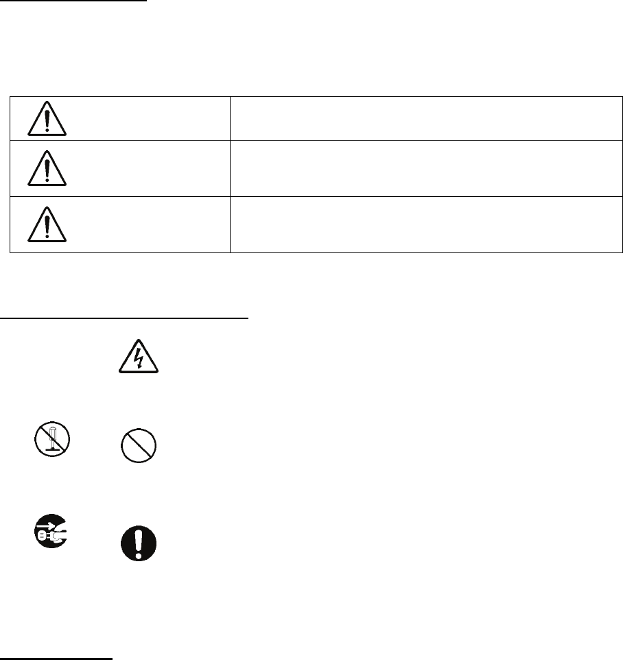
Pictorial Indication
Various pictorial indications are included in this manual and are shown on these equipment so that you can
operate them safety and correctly and prevent any danger to you and/or to other persons and any damage to
your property during operation. Such indications and their meanings are as follows.
Please understand them before you read this manual:
DANGER This indication is shown where incorrect equipment operation due to
negligence may cause death or serious injuries.
WARNING This indication is shown where any person is supposed to be in
danger of being killed or seriously injured if this indication is
neglected and these equipment are not operated correctly.
CAUTION This indication is shown where any person is supposed to be injured
or any property damage is supposed to occur if this indication is
neglected and these equipment are not operated correctly.
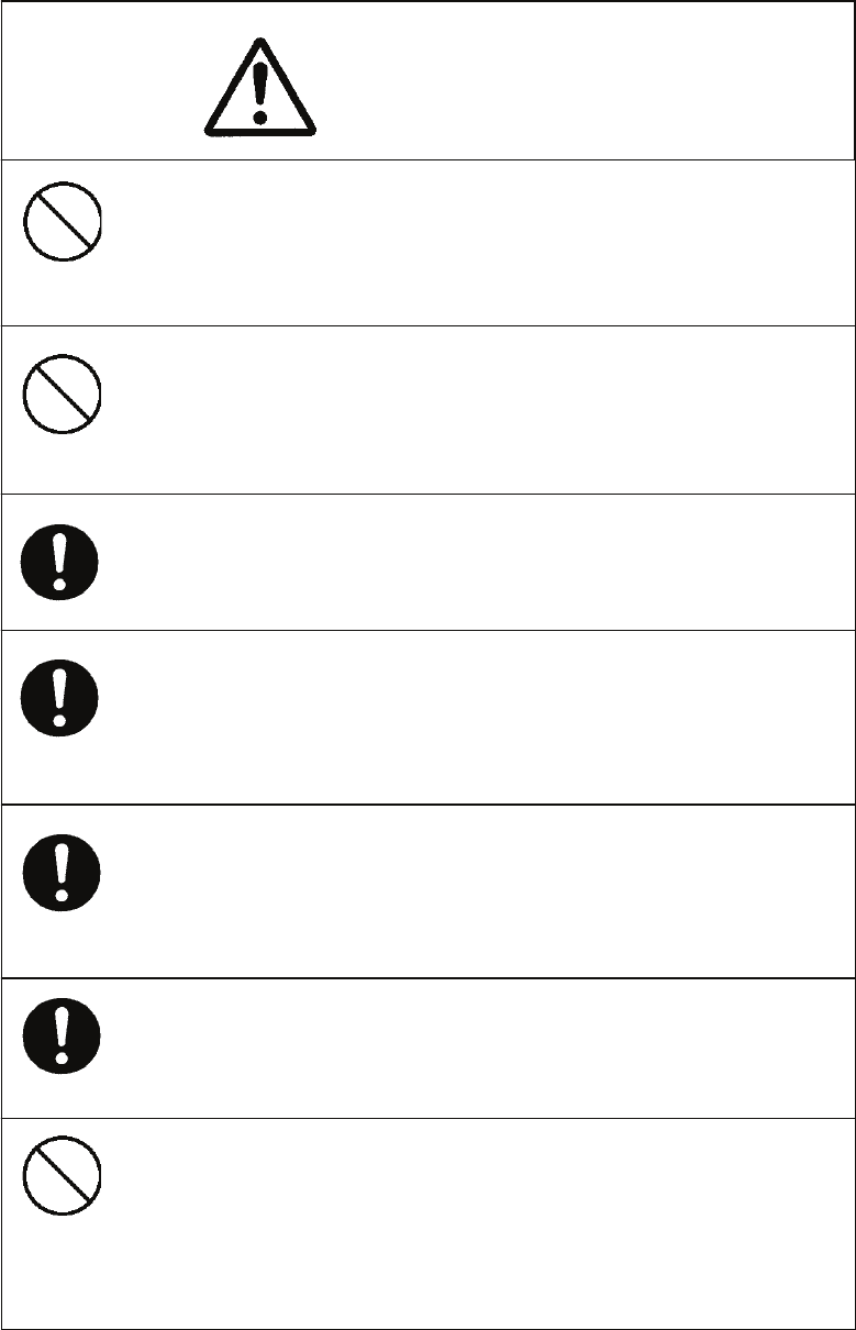
Examples of Pictorial Indication
Electric Shock
The U mark represents CAUTION (including DANGER and WARNING).
Detailed contents of CAUTION (“Electric Shock” in the example on the
left.) is shown in the mark.
Disassembling
Prohibited
Prohibited
The ; mark represents prohibition.
Detailed contents of the prohibited action (“Disassembling Prohibited” in the
example on the left.) is shown in the mark.
Disconnect
the power
plug
Instruction
The z mark represents instruction.
Detailed contents of the instruction (“Disconnect the power plug “ in the
example on the left.) is shown in the mark.
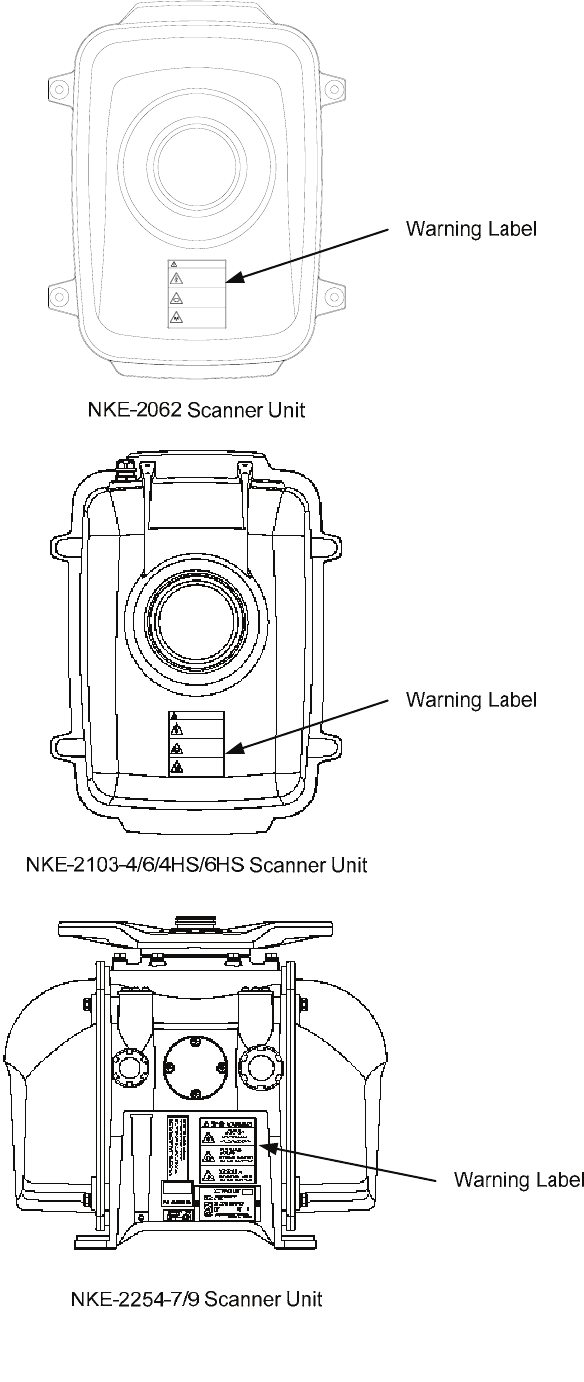
Warning Label
There is a warning label on the top cover of the equipment.
Do not try to remove, break or modify the label.

- iii -
●PRECAUTIONS●
DANGER
Never conduct inspection or repair work of equipment
components.
Inspection or repair work by uncertified personnel may
result in fire hazard or electrocution.
For inspection and repair work of equipment
components, consult with our branch office, branch
shop, sales office, or our distributor in your district.
When conducting maintenance, make sure to turn the
main power off.
Failure to comply may result in electrocution.
Turn off the main power before cleaning the equipment.
Especially when a rectifier is used, make sure to turn it
off since voltage is still outputted from the rectifier even
after the indicator and the radar are turned off. Failure to
comply may result in equipment failure, or death or
serious injury due to electric shock.
When conducting maintenance work on the antenna,
make sure to turn its main power off.
Failure to comply may result in electrocution or injuries.
Make sure to turn off the antenna operation switch.
Failure to comply may result in injuries caused by
physical contact with the rotating antenna.
Do not touch the radiator. Even if the power is turned off,
the radiator may be rotated by the wind.

- iv -
Never directly touch the internal components of the
antenna, receiver/transceiver, or indicator. Direct
contact with these high-voltage components may cause
electrocution. For maintenance, inspection, or
adjustment of equipment components, consult with our
branch office, branch shop, sales office, or our distributor
in your district.
Do not get close to the radiant section of the antenna. It
is a rotating part, and it may cause injuries if it suddenly
starts rotating and consequently hits the body. It is
recommended that the radiant section be installed at a
high place such as on the roof of the wheelhouse, on the
flying bridge, on the trestle, or on the radar mast so that
no one can get close to it. When any work must be done
on the antenna, make sure to turn the antenna switch off.
WARNING
Microwave radiation level:
Keep away from a scanner when it is transmitting.
The high level of microwave is radiated from the front
face of the scanner specified below. The microwave
exposure at close range could result in injuries
(especially of the eyes).
System 50W/m2 10W/m2 2.5W/m2
NKE-2062
NKE-2103 n/a 26cm 123cm
NKE-2254 5cm 81cm 162cm
Make sure to install the antenna at a place higher than
human height.
Direct exposure to electromagnetic waves at close range
will have adverse effects on the human body.

- v -
WARNING
When conducting maintenance work, make sure to turn
off the power and unplug the power connector J1 of the
radar process unit so that the power supply to the
equipment is completely cut off.
Some equipment components can carry electrical current
even after the power switch is turned off, and conducting
maintenance work without unplugging the power
connector may result in electrocution, equipment failure,
or accidents.
Direct exposure to electromagnetic waves at close range
will have adverse effects on the human body. When it is
necessary to get close to the antenna for maintenance or
inspection purposes, make sure to turn the indicator
power switch to "OFF" or "STBY."
Direct exposure to electromagnetic waves at close range
will have adverse effects on the human body.
When cleaning the display screen, do not wipe it too
strongly with a dry cloth. Also, do not use gasoline or
thinner to clean the screen. Failure to comply will result
in damage to the screen surface.
When disposing of used lithium batteries, be sure to
insulate the batteries by attaching a piece of adhesive
tape on the ⊕ and { terminals. Failure to comply may
cause heat generation, explosion, or fire when the
batteries get shorted out.
Do not change MBS Level/Area unless absolutely
necessary.
Incorrect adjustment will result in deletion of nearby
target images and thus collisions may occur resulting in
death or serious injuries.

- vi -
CAUTION
When using the [AUTO SEA] function, never set the
suppression level too high canceling out all image noises
from the sea surface at close range.
Detection of not only echoes from waves but also targets
such as other ships or dangerous objects will become
inhibited.
When using the [AUTO SEA] function, make sure to
choose the most appropriate image noise suppression
level.
A malfunction may occur if the power in the ship is
instantaneously interrupted during operation of the radar.
In this case, the power should be turned on again.
If sensitivity is set too high, unnecessary signals such as
noises in the receiver and false echoes increase to lower
target visibility.
At the same time, if sensitivity is set too low, detection of
targets such as ships and dangerous objects may be
hindered.
Therefore, sensitivity must always be set to an optimal
level.
Always use the automatic tuning mode.
Use the manual tuning mode only when the automatic
tuning mode does not provide the best tuning state due
to deterioration of magnetron for example.

- vii -
Use the radar only as a navigation aid. The final
navigation decision must always be made by the operator
him/herself. Making the final navigation decision based
only on the radar display may cause accidents such as
collisions or running aground.
CAUTION
When using the [AUTO RAIN] function, never set the
suppression level too high canceling out all image noises
from the rain or snow at close range.
Detection of not only echoes from the rain or snow but
also targets such as other ships or dangerous objects will
become inhibited.
When using the [AUTO RAIN] function, make sure to
choose the most appropriate image noise suppression
level.
When the chart position is corrected, the display will be
shifted away from the actual position. With this in mind,
navigate your ship with attention to the surroundings.
Otherwise, this may cause accidents.
Compact Flash Cards can be used with this system. The
following shows the recommendations in use. However
they do not guarantee that CF cards may properly work
with this system. Depending on the hardware or software,
the cards will not work correctly.
Any damage including loss of data caused by using the
data created on this system is out of warranty.
Important files should be backed up therefore.

- viii -
Use the target tracking function (TT) only as a navigation
aid. The final navigation decision must always be made
by the operator him/herself. Making the final navigation
decision based only on the target tracking function (TT)
information may cause accidents.
The target tracking function (TT) information such as
vector, target numerical data, and alarms may contain
some errors. Also, targets that are not detected by the
radar cannot be acquired or tracked.
Making the final navigation decision based only on the
radar display may cause accidents such as collisions or
running aground.
CAUTION
When a large value is set as an association condition, a
tracked target near an AIS target is identified as the AIS
target and may thus disappear from the display.
For example, when a pilot vessel equipped with the AIS
function (a small target which is not a tracked target)
goes near a cargo vessel which is a tracked target
without the AIS function, the tracked target symbol for the
cargo vessel may disappear.
Target Tracking Function Test is provided to test if the
target tracking function is operating normally. Thus, do
not use the function except when you test the target
tracking function.
Note especially that, if this function is used during actual
navigation, simulated targets are displayed and may
become confused with other actual targets. Therefore,
never use this function during actual navigation.

- ix -
Any adjustments must be made by specialized service
personnel.
Incorrect settings may result in unstable operation.
Do not make any adjustments during navigation. Failure
to comply may result in adverse effects on the radar
function which may lead to accidents or equipment
failure.
When a small value is set as a hysteresis condition, a
tracked target near an AIS target is identified as the AIS
target and may thus disappear from the display.
For example, when a pilot vessel equipped with the AIS
function (a small target which is not a tracked target)
goes near a cargo vessel which is a tracked target
without the AIS function, the tracked target symbol for the
cargo vessel may disappear.
Since these alarms may include some errors depending
on the target tracking conditions, the navigation officer
himself should make the final decision for ship
operations such as collision avoidance.
Making the final navigation decision based only on the
alarm may cause accidents such as collisions.
CAUTION
When setting a automatic acquisition zone, make sure to
properly adjust gain, sea-surface reflection suppression
level, and rain/snow reflection suppression level so that
the optimal target images are always on the radar screen.
The automatic acquisition zone alarm will not be
activated for targets undetected by the radar, and it may
result in accidents such as collisions.
Optimal values have been set for Video Level and Vector
Constant; therefore, never change their values unless
absolutely necessary. Failure to comply may result in
accidents that would lower target tracking performance.
- x -
CAUTION
Do not change the quantization level settings unless
absolutely necessary. If set at an inappropriate value,
the acquisition or tracking function of the target tracking
function (TT) deteriorates, and this may lead to accidents.
Make sure to shut off the main power before replacing
parts. Failure to comply may result in electrocution or
equipment failure.
When replacing magnetrons, make sure to shut off the
main power and let the equipment stand for more than 5
minutes to discharge the high-voltage circuit. Failure to
comply may result in electrocution.
Make sure to take off your watch when your hand must
get close to the magnetron.
Failure to comply may result in damage to the watch
since the magnetron is a strong magnet.
Make sure that two or more staff member work together
when replacing the LCD. If only one person attempts to
replace the LCD, he/she may drop it and become injured.
Do not directly touch the inverter circuit of the LCD
display with a bare hand since high voltage temporarily
remains in the circuit even after the main power is shut
off.
Failure to comply may result in electrocution.
Any adjustments must be made by specialized service
personnel.
Failure to comply may result in accidents or equipment
failure.

- xi -
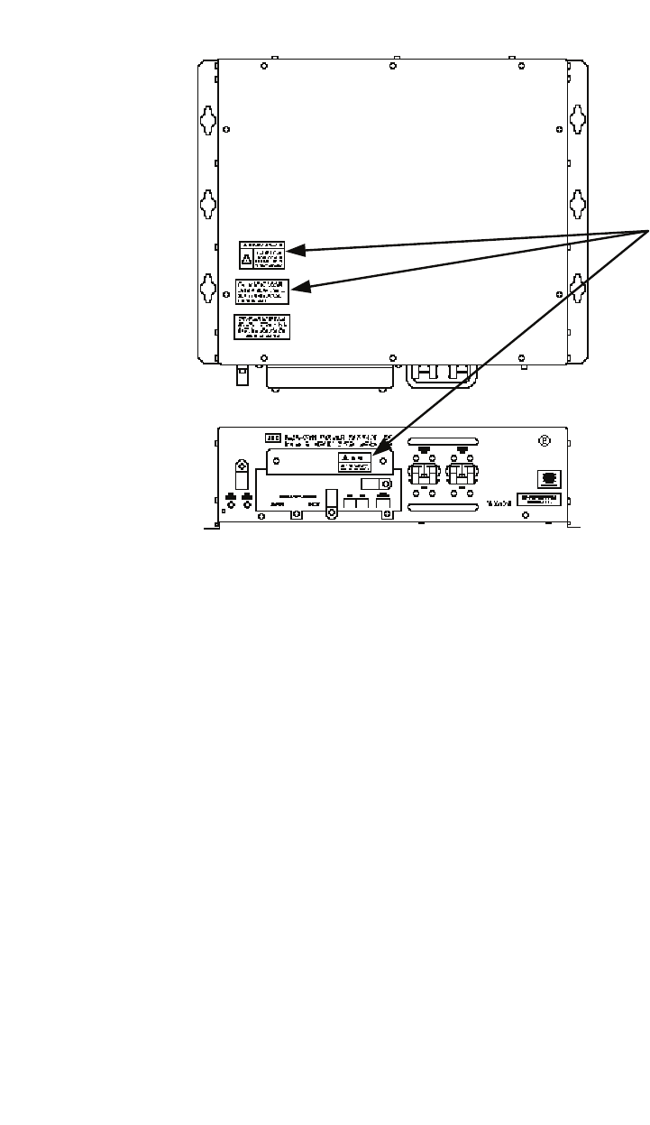
The Mounting Point of the Warning Label
Warning Label
Warning Label
NCD-4380 Radar Process Unit
Front face Back face
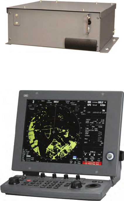
NWZ-164 LCD Monitor
- xii -
- xiii -
NBA-5111 Power Supply
Warning Label

- xiv -
EQUIPMENT APPEARANCE
Scanner Unit Type NKE-2062
Scanner Unit Type NKE-2103-4/4HS (4 feet)
Scanner Unit Type NKE-2103-6/6HS (6 feet)
Scanner Unit Type NKE-2254-7 (7 feet)

- xv -
Scanner Unit Type NKE-2254-9 (9 feet)
- xvi -
NDC-1460 Processor Unit (Desktop Type)
NWZ-164 Display Unit (Desktop Type)
NCE-7699A Operation Unit (Desktop Type)
NCD-4380 Display Unit (Desktop Type)

- xvii -
CONTENTS
PREFACE................................................................................................................i
BEFORE OPERATION ...........................................................................................ii
PRECAUTIONS..................................................................................................... iii
THE MOUNTING POINT OF THE WARNING LABEL...........................................xi
EQUIPMENT APPEARANCE .............................................................................. xiv
GLOSSARY....................................................................................................... xxvi
1. GENERAL AND EQUIPMENT COMPOSITION
1.1 FUNCTIONS........................................................................................... 1-1
1.1.1 Function of This System ..................................................................... 1-1
1.2 FEATURES............................................................................................. 1-2
1.3 CONFIGURATION .................................................................................. 1-4
1.4 EXTERIOR DRAWINGS......................................................................... 1-5
1.5 GENERAL SYSTEM DIAGRAMS ......................................................... 1-15
2. SCREEN DISPLAY AND OPERATION PANEL
2.1 EXAMPLE OF DISPLAY ......................................................................... 2-1
2.2 NAMES AND FUNCTIONS OF CONTROL PANEL KEYS...................... 2-2
2.3 FUNCTIONS OF SOFTWARE BUTTONS.............................................. 2-7
2.3.1 Software Buttons for Area 1
(Top-Left Corner of the Radar Display)............................................. 2-8
2.3.2 Software Buttons for Area 2
(Bottom-Left Corner of the Radar Display) ..................................... 2-10
2.3.3 Software Buttons for Area 3
(Top-Right Corner of the Radar Display)......................................... 2-12
2.3.4 Software Buttons for Area 4
(Bottom-Right Corner of the Radar Display)................................... 2-14
2.3.5 Software Buttons for Area 5
(Own Ship Information Area) (Right Side of the Radar Display) ..... 2-15
- xviii -
2.3.6 Software Buttons for Area 6
(Other Ship Information Area) (Right Side of the Radar Display)....2-16
2.3.7 Software Buttons for Area 7
(Panel Display Area) (Right Side of the Radar Display) ..................2-18
2.3.8 Software Buttons for Area 7
(Panel Display Area) (Right Side of the Radar Display) ..................2-19
2.3.9 Software Buttons for Area 8 (Operation and Message Area)
(Right Side of the Radar Display)....................................................2-20
3. BASIC OPERATION
3.1 FLOW OPERATION................................................................................3-1
3.1.1 Power ON and Start the System .........................................................3-2
3.1.2 Observe and Adjust Video...................................................................3-3
3.1.3 Acquire and Measure Data..................................................................3-4
3.1.4 Display and Measure with Reference to CCRP...................................3-4
3.1.5 End the Operation and Stop the System .............................................3-5
3.2 MENU COMPOSITION ...........................................................................3-6
3.2.1 Overview of Menu Structure................................................................3-6
3.2.2 Basic Menu Operation.........................................................................3-7
3.3 PREPARATION.......................................................................................3-9
3.3.1 Adjust Display Brilliance [BRILL] .........................................................3-9
3.3.2 Adjust Contrast....................................................................................3-9
3.3.3 Adjust Operation Panel Brilliance [PANEL] .......................................3-10
3.3.4 Switch Day/Night Mode [DAY/NIGHT]...............................................3-10
3.3.5 Adjust Brilliance of Information on Radar Display
(Brilliance Setting)........................................................................... 3-11
3.3.6 Adjust Sound Volume (Buzzer Volume).............................................3-12
3.3.7 Reset Alarm Buzzer [ALARM ACK] ...................................................3-12
3.3.8 Set Display Color ..............................................................................3-13
3.4 BASIC OPERATIONS ...........................................................................3-15
3.4.1 Start Transmission [TX/PRF] .............................................................3-15
3.4.2 Stop Transmission [STBY].................................................................3-15
3.4.3 Change Range (Observation Range Scale) [RANGE+/-]..................3-15
3.4.4 Tune ..................................................................................................3-16
3.4.5 Control Sensitivity [GAIN/PL] ............................................................3-17
3.4.6 Suppress Sea Clutter [AUTO-SEA]...................................................3-18
3.4.7 Suppress Rain/Snow Clutter [AUTO-RAIN].......................................3-20
3.4.8 Reject Radar Interference [IR]...........................................................3-22
3.4.9 Hide/Display Range Rings (RINGS)..................................................3-23
- xix -
3.4.10 Hide Ship’s Heading Line (HL OFF)................................................ 3-23
3.4.11 Hide Graphics Information on Radar Display (Graphic Display)...... 3-24
3.5 GENERAL OPERATIONS..................................................................... 3-25
3.5.1 Move Cross Cursor Mark by Trackball.............................................. 3-25
3.5.2 Use EBLs (Electronic Bearing Lines) [EBL1/2] ................................. 3-26
3.5.3 Set EBL Operation (EBL1 /2 Setting)................................................ 3-29
3.5.4 Display Variable Range Markers [VRM1/VRM2]............................... 3-32
3.5.5 Display Parallel Cursors (Parallel Cursor)......................................... 3-34
3.5.6 Display Parallel Index Lines (Parallel Index Line) ............................. 3-41
3.5.7 Switch Bearing Display Mode [AZI MODE]....................................... 3-48
3.5.8 Switch True/Relative Motion Display Mode [TM/RM] ........................ 3-49
3.5.9 Move Own Ship’s Display Position [OFF CENT]............................... 3-50
3.5.10 Display Radar Trails (Other Ships’ Trails) [TRAILS]........................ 3-51
3.5.11 Switch Pulse Length (GAIN/PL) ...................................................... 3-54
3.5.12 Expand Targets (Target Enhance)................................................... 3-55
3.5.13 Use Video Process (Process) ......................................................... 3-56
3.5.14 Zoom............................................................................................... 3-57
3.5.15 Use Marker [MOB] .......................................................................... 3-58
3.5.16 Marking [MARK].............................................................................. 3-59
3.5.17 Operate EBL Maneuver Function (EBL Maneuver)......................... 3-60
3.5.18 Operate Multi-Function Control [MULTI] ......................................... 3-62
3.5.19 Operate User Key Switches [User Key 1/2] .................................... 3-64
3.5.20 Automatic Acquisition...................................................................... 3-66
3.5.21 Radar Alarm (Radar Alarm)............................................................. 3-69
3.6 USE OWN SHIP'S TRACK DATA (OWN TRACK).............................. 3-74
3.6.1 Display Own Ship’s Track (Display Own Track) ................................ 3-74
3.6.2 Set Own Ship’s Track Data Storage Interval (Own Track Interval).... 3-76
3.6.3 Cancel Storing of Own Ship’s Track Data (Own Track Memory)....... 3-77
3.6.4 Clear Own Ship’s Track Data (Clear Own Track) .............................. 3-78
3.7 DISPLAY CHARTS ............................................................................... 3-79
3.7.1 Insert/Remove a Card....................................................................... 3-79
3.7.2 Display Coastline ROM Card Produced by JRC ............................... 3-81
3.7.3 Display ERC Card............................................................................. 3-82
3.7.4 Fill Charts (Fill Land Area) ................................................................ 3-83
3.8 DISPLAY NAVIGATION INFORMATION
(NAV INFORMATION DISPLAY)........................................................... 3-84
3.8.1 Display Waypoint Marks (Waypoint Display)..................................... 3-84
3.8.2 Display Navigation Information (NAV Display Setting) ...................... 3-85
3.8.3 Create/Edit Navigation Information (Edit User Map) ......................... 3-86
- xx -
3.8.4 Set Navigation Information (User Map Setting) .................................3-92
3.8.5 Set and Display Geodetic System.....................................................3-99
3.9 APPLIED OPERATIONS.....................................................................3-101
3.9.1 Set Radar Signal Processing (Process Setting) ..............................3-101
3.9.2 Set Radar Trails (RADAR Trails Setting).........................................3-104
3.9.3 Set Cursor (Cursor Setting).............................................................3-109
3.9.4 Set Screen(Screen Setting)............................................................. 3-111
3.9.5 Set Scanner (TXRX Setting) ...........................................................3-121
3.9.6 Set Chart Display (Map Setting)......................................................3-123
3.9.7 Set LORAN C (LORAN C Correction) .............................................3-135
3.10 USE FUNCTION SWITCH [FUNC] .....................................................3-136
3.10.1 Operation Procedure.....................................................................3-136
3.10.2 Function Setting Menu Items.........................................................3-137
3.10.3 Overview of Function Operations ..................................................3-138
3.10.4 Overview of Stored Function Setting Data.....................................3-142
3.10.5 Personal Information (PIN Setting)................................................3-143
3.11 USING CARD......................................................................................3-146
3.11.1 Save in and Transfer to Card (MEM CAPA/Copy) .........................3-147
3.11.2 Erase/Initialize Card Memory (CLR MEM/INIT Card) ....................3-152
4. MEASUREMENT OF RANGE AND BEARING
4.1 MEASUREMENT USING THE CURSOR WITH THE TRACKBALL........4-1
4.2 MEASUREMENT BY RANGE RINGS.....................................................4-2
4.3 MEASUREMENT BY EBLS AND VRMS.................................................4-3
4.4 MEASUREMENT BETWEEN TWO OPTIONAL POINTS .......................4-4
5. OPERATION OF TT AND AIS
5.1 PREPARATION.......................................................................................5-2
5.1.1 Collision Avoidance .............................................................................5-3
5.1.2 Definitions of Symbols.........................................................................5-6
5.1.3 TT Data Display................................................................................. 5-11
5.1.4 Cursor Modes (Cursor)......................................................................5-13
5.1.5 Setting Collision Decision Criteria (CPA/TCPA Limit) ........................5-14
5.1.6 Setting CPA Ring (CPA Ring) ............................................................5-15
5.1.7 Setting Vectors (Vector Time)..........................................................5-16
5.1.8 Setting the GPS antenna location ...................................................5-17
- xxi -
5.2 TT OPERATION.................................................................................... 5-18
5.2.1 Acquiring Target [ACQ] ..................................................................... 5-19
5.2.2 Canceling Unwanted Targets ............................................................ 5-22
5.2.3 Tracking Target Data Display [TGT DATA] ........................................ 5-23
5.2.4 Displaying Target ID No. (Target Number Display)............................ 5-25
5.2.5 Input of target information (TT Individual Setting) ............................. 5-26
5.2.6 Reference Target (Reference)........................................................... 5-29
5.2.7 TT Test Menu.................................................................................... 5-31
5.3 AIS OPERATION .................................................................................. 5-37
5.3.1 Restrictions ....................................................................................... 5-37
5.3.2 Initial Setting ..................................................................................... 5-38
5.3.3 Setting AIS Display Function (AIS Function)..................................... 5-40
5.3.4 Activating AIS Targets (Activate AIS) ................................................ 5-41
5.3.5 Deactivating AIS Targets (Deactivate AIS) ........................................ 5-42
5.3.6 Displaying Numeric Data of AIS Targets (TGT DATA)....................... 5-43
5.3.7 Displaying Target ID No. (Target Number Display)............................ 5-48
5.3.8 Setting AIS Filter (AIS Filter Setting)................................................. 5-49
5.3.9 Conditions for Deciding AIS Target to be Lost................................... 5-53
5.3.10 Setting AIS Alarm (AIS Alarm Setting)............................................. 5-54
5.4 TARGET ASSOCIATION ASSESSMENT (ASSOCIATION SETTING) . 5-55
5.4.1 Target Association Assessment ........................................................ 5-55
5.4.2 Priority............................................................................................... 5-56
5.4.3 Azimuth............................................................................................. 5-56
5.4.4 Distance............................................................................................ 5-57
5.4.5 Course .............................................................................................. 5-57
5.4.6 Speed................................................................................................ 5-58
5.4.7 Hysteresis ......................................................................................... 5-59
5.4.8 Non-Hysteresis ................................................................................. 5-60
5.4.9 AIS Target to be Assessed................................................................ 5-61
5.5 ALARM DISPLAY.................................................................................. 5-62
5.6 TRACK DISPLAY.................................................................................. 5-68
5.6.1 Display Past Tracks (Past Position) .................................................. 5-68
5.6.2 Other Ship's Tracks (Target Track Setting)........................................ 5-69
6. TRUE AND FALSE ECHOES ON DISPLAY
6.1 RADAR WAVE WITH THE HORIZON .................................................... 6-2
6.2 STRENGTH OF REFLECTION FROM THE TARGET............................ 6-4
6.3 SEA CLUTTER AND RAIN AND SNOW CLUTTER................................ 6-6
- xxii -
6.4 FALSE ECHOES...................................................................................6-10
6.5 DISPLAY OF RADAR TRANSPONDER (SART)...................................6-13
7. SETTINGS FOR SYSTEM OPERATION
7.1 SETTINGS AT INSTALLATION ...............................................................7-1
7.1.1 How to open the Adjust Menu .............................................................7-2
7.1.2 Tuning Adjustment...............................................................................7-3
7.1.3 Bearing Adjustment .............................................................................7-6
7.1.4 Range Adjustment...............................................................................7-7
7.1.5 Antenna Height Setting (Antenna Hight) .............................................7-8
7.1.6 Setting of CCRP/Antenna/GPS Antenna Position (CCRP Setting)......7-9
7.2 NAVIGATOR SETTING ......................................................................... 7-11
7.2.1 Ship Heading Equipment Setting (Heading Equipment)....................7-14
7.2.2 NSK Unit Setting ...............................................................................7-15
7.2.3 True Bearing Value Setting (Set GYRO) ...........................................7-17
7.2.4 MAG Compass Setting......................................................................7-18
7.2.5 Ship Speed Equipment Setting (Speed Equipment)..........................7-19
7.2.6 Manual Speed Setting (Manual Speed).............................................7-20
7.2.7 Current Correction (SET/DRIFT) Setting...........................................7-21
7.3 SETTINGS ............................................................................................7-23
7.3.1 Communication Port Setting (COM Port Setting) ..............................7-23
7.3.1.1 Baud Rate Setting.....................................................................7-24
7.3.1.2 Reception Port Setting (RX Port) ..............................................7-26
7.3.1.3 Reception Sentence Setting (RX Sentence) .............................7-27
7.3.1.4 Transmission Port Setting (TX Port)..........................................7-29
7.3.2 Sector Blank Setting (Sector Blank) ..................................................7-31
7.3.3 TNI Blank Setting (TNI Blank) ...........................................................7-33
7.3.4 Bearing Pulse Output Adjustment (Output Pulse) .............................7-35
7.3.5 Language Setting (Language)...........................................................7-36
7.3.6 Date/Time Display Setting (Date/Time Setting) .................................7-37
7.4 ADJUSTMENT ......................................................................................7-38
7.4.1 Noise Level Adjustment (Noise Level)...............................................7-39
7.4.2 Adjustment of Target Tracking Function (TT) ....................................7-41
7.4.3 Main Bang Suppression Adjustment (MBS Level).............................7-46
7.4.4 Adjustment of Performance Monitor (NJU-85) ..................................7-48
7.5 MAINTENANCE MENU.........................................................................7-50
7.5.1 Scanner Safety Switch Setting (Safety Switch) .................................7-51
7.5.2 Initialization of Memory Area (Area Initial).......................................7-52
- xxiii -
7.5.3 Save of Internal Memory Data (Card2) ............................................. 7-54
7.5.4 Update of Character String Data (String Data Update) ..................... 7-56
7.5.5 Clear of Antenna Operation Time (TXRX Time CLR)........................ 7-57
7.5.6 Update of AIS Processor Program (AIS PROC Program Update) .... 7-61
8. MAINTENANCE AND INSPECTION
8.1 ROUTINE MAINTENANCE..................................................................... 8-1
8.2 MAINTENANCE ON EACH UNIT ........................................................... 8-2
8.2.1 Scanner Unit NKE-2062/2103/2254.................................................... 8-2
8.2.2 Display Unit NCD-4380....................................................................... 8-5
8.3 PERFORMANCE CHECK ...................................................................... 8-6
8.3.1 Test Menu ........................................................................................... 8-7
8.3.1.1 Self-diagnosis function................................................................ 8-8
8.3.1.2 Monitor Test .............................................................................. 8-10
8.3.1.3 Operation Panel Test .................................................................8-11
8.3.1.4 MON Display............................................................................. 8-13
8.3.1.5 Alarm Logging........................................................................... 8-14
8.3.1.6 System INFO ............................................................................ 8-17
8.3.1.7 MAGI ........................................................................................ 8-18
8.3.2 Line Monitor ...................................................................................... 8-19
8.3.3 GPS Reception Status Display (GPS Status).................................... 8-21
8.4 REPLACEMENT OF MAJOR PARTS................................................... 8-23
8.4.1 Parts Required for Periodic Replacement......................................... 8-25
8.4.2 Replacement of magnetron............................................................... 8-25
8.4.3 Motor Replacement........................................................................... 8-34
8.4.4 Replacement of Diode Limiter (A303)............................................... 8-43
8.4.5 Replacement of Backup Battery ....................................................... 8-44
9. TROUBLESHOOTING AND AFTER-SALES SERVICE
9.1 FAULT FINDING ..................................................................................... 9-1
9.1.1 List of Alarms and other Indications .................................................... 9-1
9.1.2 Operation Checking ............................................................................ 9-4
9.1.3 Fuse Checking.................................................................................... 9-4
9.2 TROUBLE SHOOTING........................................................................... 9-5
9.2.1 Spares................................................................................................. 9-6
9.2.2 Special Parts....................................................................................... 9-8
9.2.3 Circuit Block to be Repaired................................................................ 9-8
- xxiv -
9.3 AFTER-SALES SERVICE..................................................................... 9-11
9.3.1 Keeping period of maintenance parts................................................ 9-11
9.3.2 When you Request for Repair ........................................................... 9-11
9.3.3 Recommended Maintenance ............................................................ 9-11
10. DISPOSAL
10.1 DISPOSAL OF THE UNIT.....................................................................10-1
10.2 DISPOSAL OF USED BATTERIES.......................................................10-2
10.3 DISPOSAL OF USED MAGNETRON ...................................................10-3
10.4 ABOUT THE CHINA ROHS...................................................................10-4
11. SPECIFICATIONS
11.1 JMA-5208/HS TYPE RADAR ................................................................ 11-1
11.2 JMA-5212-4/6/4HS/6HS TYPE RADAR ................................................ 11-2
11.3 JMA-5222-7/9 TYPE RADAR................................................................ 11-3
11.4 SCANNER (NKE-2062)......................................................................... 11-4
11.5 SCANNER (NKE-2062HS).................................................................... 11-5
11.6 SCANNER (NKE-2103-4/6)................................................................... 11-6
11.7 SCANNER (NKE-2103-4HS/6HS)......................................................... 11-7
11.8 SCANNER (NKE-2254-7/9)................................................................... 11-8
11.9 DISPLAY UNIT (NCD-4380).................................................................. 11-9
11.10 PROCESSOR UNIT (NDC-1460)........................................................ 11-10
11.11 TARGET TRACKING UNIT (NCA-877A)............................................. 11-12
11.12 AIS UNIT (NQA-2155)......................................................................... 11-13
11.13 PLOTTER UNIT .................................................................................. 11-14
11.14 KEYBOARD UNIT (NCE-7699A)......................................................... 11-16
11.15 PERFORMANCE MONITOR (NJU-85) ............................................... 11-17
11.16 INPUT ENABLE SIGNAL .................................................................... 11-17
11.17 OUTPUT ENABLE SIGNAL ................................................................ 11-18
11.18 STANDARD CONFIGURATION.......................................................... 11-18
11.19 EQUIPMENT DISTANCE BETWEEN OTHER INSTRUMENTS ......... 11-19
11.20 OTHERS (OPTION) ............................................................................ 11-19
- xxv -
APPENDIX
FIGURE 1 JMA-5208/HS, JMA-5212-4/6/4HS/6HS, JMA-5222-7/9
BLOCK DIAGRAM
FIGURE 2 JMA-5208/HS INTER-CONNECTION DIAGRAM
FIGURE 3 JMA-5212-4/6/4HS/6HS INTER-CONNECTION DIAGRAM
FIGURE 4 JMA-5222-7/9 INTER-CONNECTION DIAGRAM
FIGURE 5 PRIMARY POWER SUPPLY DIAGRAM,
TYPE JMA-5208/HS, JMA-5212-4/6/4HS/6HS, JMA-5222-7/9
FIGURE 6 PROCESSOR UNIT, NDC-1460 INTER-CONNECTION DIAGRAM
FIGURE 7 KEY-BOARD UNIT, NCE-7699A INTER-CONNECTION DIAGRAM
FIGURE 8 NKE-2062 SCANNER UNIT INTERCONNECTION DIAGRAM
FIGURE 9 NKE-2062HS SCANNER UNIT INTERCONNECTION DIAGRAM
FIGURE 10 NKE-2103 SCANNER UNIT INTERCONNECTION DIAGRAM
FIGURE 11 NKE-2254 INTERCONNECTION DIAGRAM OF SCANNER UNIT
FIGURE 12 JMA-5200MK2 ON-SCREEN CONTROLS

- xxvi -
GLOSSARY
This section describes the main terms used for this equipment and general related maritime terms.
A
AZ
Acquisition/Activation zone
A zone set up by the operator in which the system should automatically
acquire radar targets and activate reported AIS targets when entering the
zone.
Activated target A target representing the automatic or manual activation of a sleeping
target for the display of additional information.
AIS Automatic Identification System
A system which enables ships and shore stations to obtain identifying
and navigation information about other ships at sea, using an automated
transponder.
Anti-clutter rain Rain/snow clutter suppression.
Anti-clutter sea Sea clutter suppression.
Associated target A target simultaneously representing a tracked target and a reported AIS
target having similar parameters (position, course, speed) which comply
with an association algorithm.
AZI AZImuth stabilization mode
B
BCR/BCT Bow Crossing Range and Bow Crossing Time
C
C up Course up
Own ship’s course is pointed to the top center of the radar display.
CCRP The Consistent Common Reference Point
A location on own ship, to which all horizontal measurements such as
target range, bearing, relative course, relative speed, CPA or TCPA are
referenced, typically the conning position of the bridge.
Clutter Unwanted reflections on a radar screen, from sea surface, rain or snow.
COG Course Over Ground
The direction of the ship's movement relative to the earth, measured on
board the ship, expressed in angular units from true north
- xxvii -
CORREL CORRELation
CPA/TCPA The distance to the Closest Point of Approach and Time to the Closest
Point of Approach. Limits are set by the operator and are related to
own ship.
CTW Course Through Water
The direction of the ship's movement through the water
D
DRIFT The current velocity for manual correction or the current speed on the
horizontal axis of the 2-axis log is displayed.
E
EBL Electronic Bearing Line
An electronic bearing line originated from own ship’s position.
ENH Enhance
ETA Estimated Time of Arrival
G
Ground
stabilization A display mode in which speed and course information are referred to
the ground, using ground track input data.
H
HDG Heading
The horizontal direction that the bow of a ship is pointing at any instant,
expressed in angular units from a reference direction .
HL Heading line
A graphic line on a radar presentation drawn from the consistent
common reference point to the bearing scale to indicate the heading of
the ship
HSC Vessels which comply with the definition in SOLAS for high speed
craft
H up Head up
Own ship’s heading line is always pointed to the top center of the radar
display.
I
IMO International Maritime Organization
Interswitch Unit A device to switch over two or more radar display units and two or
more scanners.
IR radar Interference Rejecter
- xxviii -
ISW InterSWitch L
Lost AIS target A target symbol representing the last valid position of an AIS target
before the reception of its data was lost, or its last dead-reckoned
position.
Lost tracked target One for which target information is no longer available due to poor, lost
or obscured signals.
LP Long Pulse M
MMSI Maritime Mobile Service Identity
MOB Man OverBoard
MON Performance monitor
MP Medium Pulse N
nm 1nm=1852m
NSK North Stabilization Kit
N up North up
The north is always pointed to the top center of the radar display.
O
Own track Display function of own ship’s track
P
PI Parallel Index line
Past positions Equally time-spaced past position marks of a tracked or AIS target and
own ship.
POSN POSitioN
PRF Pulse Repetition Frequency
The number of radar pulses transmitted each second.
PROC PROCess
Radar signal processing function
R
Radar beacon A navigation aid which responds to the radar transmission by generating
a radar signal to identify its position and identity
- xxix -
Radar cross-section Radar cross-section of a target determines the power density returned to
the radar for a particular power density incident on the target
Range Rings A set of concentric circles labeled by distance from CCRP.
Reference target A symbol indicating that the associated tracked stationary target is
used as a speed reference for the ground stabilization
Relative course The direction of motion of a target relative to own ship motion
Relative speed The speed of a target relative to own ship’s speed data
Relative vector A predicted movement of a target relative to own ship’s motion
RM Relative Motion
A display on which the position of own ship remains fixed, and all
targets move relative to own ship.
RM(R) Relative Motion. Relative Trails.
RM(T) Relative Motion. True Trails.
ROT Rate Of Turn
Change of heading per time unit.
Route A set of waypoints.
RR Range Rings S
SART Search And Rescue Transponder
Radar transponder capable of operating in the 9GHz band
Sea stabilization A display mode in which speed and course information are referred to
the sea.
Sea state Status of the sea condition due to the weather environment, expressed as
a sea state 0 for flat conditions with minimal wind, to sea state 8 for
very rough sea conditions.
SET The current direction for manual correction or the current speed on the
horizontal axis of the 2-axis log is displayed.
Sleeping AIS target A target indicating the presence and orientation of a vessel equipped
with AIS in a certain location.
- xxx -
SOG Speed Over the Ground
The speed of the ship relative to the earth, measured on board of the
ship.
SP Short Pulse
STAB STABilization
STW Speed Through Water
The speed of the ship relative to the water surface.
T
TCPA Time to Closest Point of Approach to own ship
Test target Radar target of known characteristics used for test requirement
TM True Motion
A display across which own ship moves with its own true motion.
Trails Display Radar Trails (Other Ships' Trails)
Trial maneuver A graphical simulation facility used to assist the operator to perform a
proposed maneuver for navigation and collision avoidance purposes.
True course The direction of motion relative to ground or to sea, of a target
expressed as an angular displacement from north
True speed The speed of a target relative to ground, or to sea
True vector A vector representing the predicted true motion of a target, showing
course and speed with reference to the ground or sea
TT Target Tracking.
A computer process of observing the sequential changes in the position
of a radar target in order to establish its motion. Such a target is a
Tracked Target.
TTG Time To Go.
Time to next waypoint.
TXRX Transceiver Unit U
UTC Universal Time Coordinated.
The international standard of time, kept by atomic clocks around the
world.
- xxxi -
V
VRM Variable Range Marker
An adjustable range ring used to measure the distance to a target.
W
Waypoint A geographical location on a route indicating a event.
- xxxii -

- xxxiii -
3
4
5
2
1
6
7
8
9
10
11
APPENDIX
1 GENERAL AND EQUIPMENT COMPOSITION
2 SCREEN DISPLAY AND OPERATION PANEL
3 BASIC OPERATION
4 MEASUREMENT OF RANGE AND BEARING
5 OPERATION OF TT AND AIS
6 TRUE AND FALSE ECHOES ON DISPLAY
7 SETTINGS FOR SYSTEM OPERATION
8 MAINTENANCE AND INSPECTION
9
TROUBLESHOOTING AND AFTER-SALES SERVICE
10 DISPOSAL
11 SPECIFICATION
APPENDIX
- xxxiv -

SECTION 1
GENERAL AND EQUIPMENT
COMPOSITION
1.1 FUNCTIONS ................................................. 1-1
1.1.1 Function of This System...................... 1-1
1.2 FEATURES................................................... 1-2
1.3 CONFIGURATION........................................ 1-4
1.4 EXTERIOR DRAWINGS............................... 1-5
1.5 GENERAL SYSTEM DIAGRAMS.............. 1-15

1─1
1.1 FUNCTIONS
This equipment is a high-performance radar equipment consisting of a scanner unit, a transmitter-receiver unit
and a high resolution color LCD display unit.
1.1.1 Function of This System
The JMA-5200MK2 series is a color radar system designed to comply with the international standards of
the IMO.
The main functions include:
• sensitivity adjustment
• sea clutter and rain/snow clutter suppression
• interference rejecter
• bearing and range measurement using a cursor, fixed/variable range markers, and electronic bearing
line
• own track display
• NAV line and marker displays
• TM (True Motion) presentation
• self-diagnostic facilities
• radar performance monitoring (Performance Monitor)
• TT functions (manual/automatic, target acquisition and tracking, vector and trail displays and alarm
displays) (option)
• simple plotter functions (marker and line display, destination/route setting) (option)

1.2 FEATURES
1─2
1
y
1.2 FEATURES
Realization of Easy-to-see Screen with High Resolution
The 15-inch color LCD with high resolution of 1024 × 768 pixels can display radar images of 180 mm or more
in diameter. Even short-range targets can also be displayed as high-resolution images.
Target Detection by Latest Signal Processing Technology
The system employs the latest digital signal processing technology to eliminate undesired clutter from the radar
video signals that are obtained from the receiver with a wide dynamic range, thus improving the target
detection.
Advanced Technology Based TT Functions (Option)
The TT target acquisition and tracking performance is enhanced by the use of the fastest DSP and tracking
algorithm. So stable operation in target tracking under clutter is ensured.
• Acquisition and tracking of 30 targets.
• Hazardous conditions are represented by shapes and colors of symbols as well as sounds.
• Tracks of up to 20 target ships can be stored with a maximum of 1,500 points for each of them, and
displayed distinguished by using seven different colors.
Overlay of Radar Images, Coastlines, and Own Ship's Track
As well as operator-created NAV lines, the data of coastlines, objects such as buoys, and own ship's tracks/TT
tracks/AIS tracks, which is stored on the memory card can be superimpose-displayed with radar images and
radar trails in all display modes including the head-up mode.
Use of the optional plotter function enables the creation/display of marks and lines and the settings of
waypoints/courses.
Easy Operation with GUI
All the radar functions can be easily controlled by simply using the trackball and two switches to operate the
buttons shown on the radar display.

1─3
Improved Day/Night Mode
Two types of background colors are available in each Day/Dusk/Night mode (total 4 background colors).
Each background color can be reproduced to be suited for the user’s operating environment by simple key
operation. The radar echoes and a variety of graphics can also be represented in different colors, ensuring
easy-to-see displays.
Self-diagnostic Program Incorporated
The Self-diagnostic program always monitors all the functions of the system. If any function deteriorates, an
alarm message will appear on the radar display and an alarm sounds at the same time. Even when the system
is operating, the functionality test can be carried out. (except on some functions)
Performance Monitor (Option)
The radar performance (transmitted output power and receiving sensitivity) can appear on the radar display.
* The PM unit (NJU-85) is needed separately.
Simplified Inter-switch Operation (Option)
If an simplified inter-switch unit (option) is installed, up to two JMA-5200MK2 radars can be switched over by
performing simple operation.
* An simplified inter-switch connection cable (optional) CFQ-5251 (5m) is required separately.
Various Functions
• RADAR TRAILS (Other ship’s track display)
• TM (True Motion) display
• Head-up/North-up/Course-up display
• Own ship’s track display
• Automatic acquisition and activation area setting function

1.3 CONFIGURATION
1─4
1
y
1.3 CONFIGURATION
Scanners and Transmitted Output Powers
SCANNER TYPE TRANSMITTED
OUTPUT POWER BAND RATE OF
ROTATION CATEGORY
JMA-5208 4 FT SLOT
ANTENNA 6 KW X 27rpm
JMA-5212-4 4 FT SLOT
ANTENNA 10 KW X 27rpm CAT 3
JMA-5212-6 6 FT SLOT
ANTENNA 10 KW X 27rpm CAT 3
JMA-5222-7 7 FT SLOT
ANTENNA 25 KW X 24rpm CAT 3
JMA-5222-9 9 FT SLOT
ANTENNA 25 KW X 24rpm CAT 3
JMA-5208HS 4FT SLOT
ANTENNA 6 KW X 48rpm
JMA-5212-4HS 4 FT SLOT
ANTENNA 10 KW X 48rpm
JMA-5212-6HS 6 FT SLOT
ANTENNA 10 KW X 48rpm
Radar Configuration and Ship’s Mains
RADAR
MODEL SCANNER
UNIT PERFORMANCE
MONITOR UNIT DISPLAY UNIT SHIP’S MAINS
JMA-5208 NKE-2062 - NCD-4380 DC 12/24/32V #1
JMA-5212-4 NKE-2103-4 NJU-85 NCD-4380 DC 24V
JMA-5212-6 NKE-2103-6 NJU-85 NCD-4380 DC 24V
JMA-5222-7 NKE-2254-7 NJU-85 NCD-4380 DC 24V
JMA-5222-9 NKE-2254-9 NJU-85 NCD-4380 DC 24V
JMA-5208HS NKE-2062HS - NCD-4380 DC 24V
JMA-5212-4HS NKE-2103-4HS NJU-85 NCD-4380 DC 24V
JMA-5212-6HS NKE-2103-6HS NJU-85 NCD-4380 DC 24V
Notes:
1. An optional rectifier NBA-5111 is necessary for using Ship's Mains 100/110/115/200/220/230 VAC.
2. The scanner unit except NKE-2103 series can be equipped with a deicing heater as an option, and '-D'
shall be suffixed to the type name.
(e.g. NKE-2254-7D, NKE-2254-9D).
3. The display system NCD-4380 has a separate structure consisting of the following:
Monitor unit NWZ-164
Processor unit NDC-1460
Keyboard unit NCE-7699A
4. The ship with radar of IMO conformity must mount a PM unit.
#1 When the ship's main is DC12, the maximum cable length between the display unit and scanner unit is
20 m.

1─5
1.4 EXTERIOR DRAWINGS
Fig. 1.1 Exterior Drawing of Scanner Unit, Type NKE-2062/HS
Fig. 1.2 Exterior Drawing of Scanner Unit, Type NKE-2103-4/4HS
Fig. 1.3 Exterior Drawing of Scanner Unit, Type NKE-2103-6/6HS
Fig. 1.4 Exterior Drawing of Scanner Unit, Type NKE-2254-7
Fig. 1.5 Exterior Drawing of Scanner Unit, Type NKE-2254-9
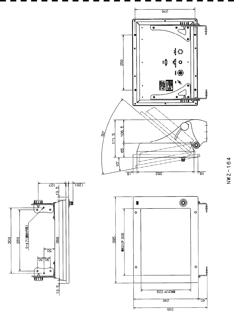
Fig. 1.6 Exterior Drawing of Monitor Unit, Type NWZ-164
Fig. 1.7 Exterior Drawing of Processor Unit, Type NDC-1460
Fig. 1.8 Exterior Drawing of Keyboard Unit, Type NCE-7699A
Fig. 1.9 Exterior Drawing of NSK Unit, Type NCT-4106A

1.4 EXTERIOR DRAWINGS
1─6
1
y
Fig. 1.1 Exterior Drawing of Scanner Unit, Type NKE-2062/HS

1─7
Fig. 1.2 Exterior Drawing of Scanner Unit, Type NKE-2103-4/4HS

1.4 EXTERIOR DRAWINGS
1─8
1
y
Fig. 1.3 Exterior Drawing of Scanner Unit, Type NKE-2103-6/6HS

1─9
Fig. 1.4 Exterior Drawing of Scanner Unit, Type NKE-2254-7

1.4 EXTERIOR DRAWINGS
1─10
1
y
Fig. 1.5 Exterior Drawing of Scanner Unit, Type NKE-2254-9
1─11
Fig. 1.6 Exterior Drawing of Monitor Unit, Type NWZ-164

1.4 EXTERIOR DRAWINGS
1─12
1
y
Fig. 1.7 Exterior Drawing of Processor Unit, Type NDC-1460

1─13
Fig. 1.8 Exterior Drawing of Keyboard Unit, Type NCE-7699A

1.4 EXTERIOR DRAWINGS
1─14
1
y
Fig. 1.9 Exterior Drawing of NSK Unit, Type NCT-4106A

1─15
1.5 GENERAL SYSTEM DIAGRAMS
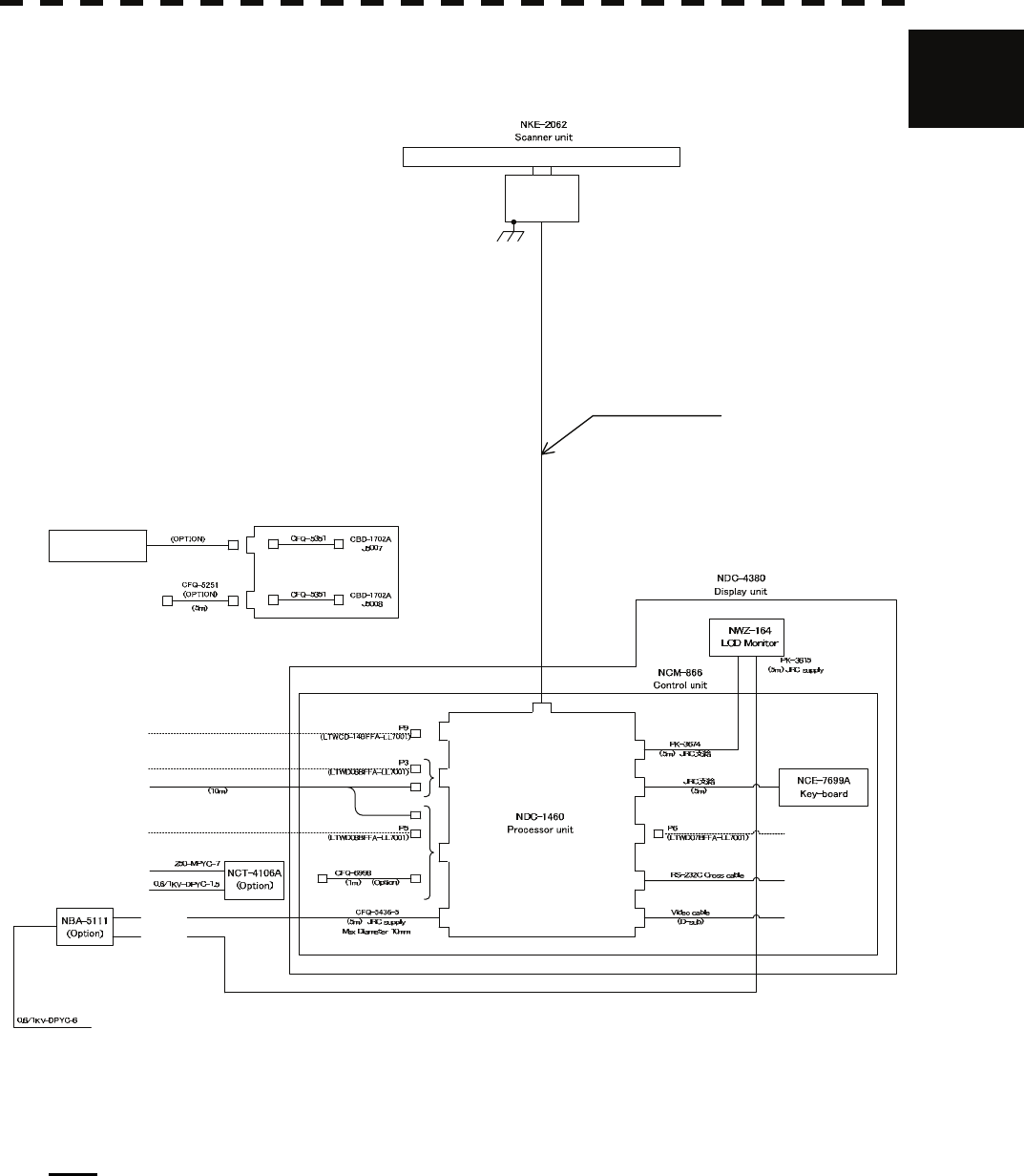
Fig. 1.10 General System Diagram of Radar, Type JMA-5208/HS
Fig. 1.11 General System Diagram of Radar, Type JMA-5212-4/6/4HS/6HS
Fig. 1.12 General System Diagram of Radar, Type JMA-5222-7/9
1.5 GENERAL SYSTEM DIAGRAMS
1─16
1
y
DC24V
Compass
(NMEA input)
J3
SCANNER
POWER
KEY-BOARD
VIDEO
CFQ-5350
(Option) RGB/VDR
AIS NMEA input
AIS/Dlog etc.
NMEA
(RS-232C) PC Plotter
J7
J4
J6
J8
J1
J2
AUX
J5
J9
GPS GPS
COMPASS
Gyro-Compass (sync/step)
Log (pulse)
DC24V
Ship's Main
JLR-10:CFQ-6934 (Option)
JLR-20/30:CFQ-5469 (Option)
AC100/110/115V 50/60Hz
AC200/220/230V 50/60Hz
NMEA input
DLog etc.
CFQ-6912(Max 65m)
JRC supply
Max Diameter 14.5mm
Max length 30m(DC24V/32V)
20m(DC12V)
DC12V and DC32V are not available to NKE-2062HS
19 CORES COMPOSITE CABLE
J9
J9
NDC-1460 Processor Unit
(Simplified Inter-switch Operation)
Sub key-board
(NCE-7699A/7729A)
Fig. 1.10 General System Diagram of Radar, Type JMA-5208/HS
Note: Install the radar cable as far as from the cables of other radio equipment in order to prevent other radio
equipment from interfering with the radar operations. In particular, do not install the antenna cable
parallel to the cables of other radio equipment.

1─17
DC24V
Compass
(NMEA input)
J3
SCANNER
POWER
KEY-BOARD
VIDEO
CFQ-5350
(Option) RGB/VDR
AIS NMEA input
AIS/Dlog etc.
NMEA
(RS-232C) PC Plotter
J7
J4
J6
J8
J1
J2
AUX
J5
J9
GPS GPS
COMPASS
Gyro-Compass (sync/step)
Log (pulse)
DC24V
Ship's Main
JLR-10:CFQ-6934 (Option)
JLR-20/30:CFQ-5469 (Option)
AC100/110/115V 50/60Hz
AC200/220/230V 50/60Hz
NMEA input
DLog etc.
CFQ-6912(Max 65m)
JRC supply
Max Diameter 14.5mm
19 CORES COMPOSITE CABLE
J9
J9
NDC-1460 Processor Unit
(Simplified Inter-switch Operation)
Sub key-board
(NCE-7699A/7729A)
Fig. 1.11 General System Diagram of Radar, Type JMA-5212-4/6/4HS/6HS
Note: Install the radar cable as far as from the cables of other radio equipment in order to prevent other radio
equipment from interfering with the radar operations. In particular, do not install the antenna cable
parallel to the cables of other radio equipment.

1.5 GENERAL SYSTEM DIAGRAMS
1─18
1
y
DC24V
Compass
(NMEA input)
J3
SCANNER
POWER
KEY-BOARD
VIDEO
CFQ-5350
(Option) RGB/VDR
AIS NMEA input
AIS/Dlog etc.
NMEA
(RS-232C) PC Plotter
J7
J4
J6
J8
J1
J2
AUX
J5
J9
GPS GPS
COMPASS
Gyro-Compass (sync/step)
Log (pulse)
DC24V
Ship's Main
JLR-10:CFQ-6934 (Option)
JLR-20/30:CFQ-5469 (Option)
AC100/110/115V 50/60Hz
AC200/220/230V 50/60Hz
NMEA input
DLog etc.
SHIP'S MAIN
J9
J9
NDC-1460 Processor Unit
(Simplified Inter-switch Operation)
Sub key-board
(NCE-7699A/7729A)
NBL-175 STEPDOWN TRANSFORMER
CIRCUIT BREAKER (5A)
(SHIPYARD SUPPLY)
HEATER CONTROL PART
0.6/1kV-DPYCYS-1.5
0.6/1kV-DPYC-1.5
AC100V 50/60Hz 1φ 100W
0.6/1kV-DPYC-1.5
CFQ-6912(Max 65m)
JRC supply
Max Diameter 14.5mm
19 CORES COMPOSITE CABLE
Fig. 1.12 General System Diagram of Radar, Type JMA-5222-7/9
Note: Install the radar cable as far as from the cables of other radio equipment in order to prevent other radio
equipment from interfering with the radar operations. In particular, do not install the antenna cable
parallel to the cables of other radio equipment.

1─19