Japan Radio NKE2062 MARINE RADAR User Manual 3
Japan Radio Co Ltd. MARINE RADAR Users Manual 3
Contents
- 1. Users Manual 1
- 2. Users Manual 2
- 3. Users Manual 3
- 4. Users Manual 4
Users Manual 3
3.8 DISPLAY NAVIGATION INFORMATION (NEW INFORMATION DISPLAY)
3─84
3
y
y y
3.8 DISPLAY NAVIGATION INFORMATION
(NAV INFORMATION DISPLAY)
Navigation information such as waypoint marks, and a maximum of 256 points of NAV lines, coastlines, depth
contours, and NAV marks can be displayed, created, read, saved, corrected, and deleted. (This function is
available only when navigation equipment is connected with the system.)
Note: Navigation information is available between latitudes of 85ºN and 85ºS.
3.8.1 Display Waypoint Marks (Waypoint Display)
When waypoint information is received from the navigation equipment, the waypoint mark appears on the
radar display. In this case, ◎W is indicated as the waypoint mark on the radar display.
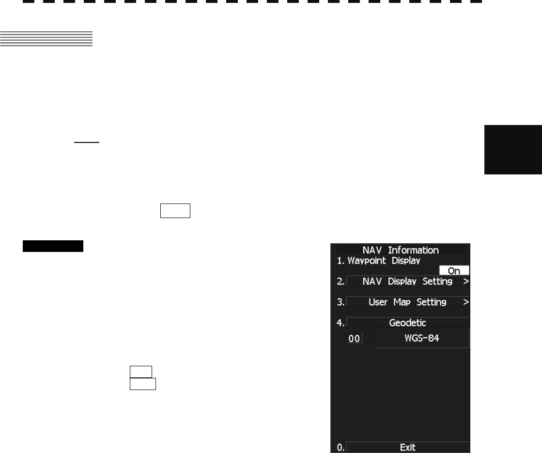
Procedure 1 Press [RADAR MENU] key twice.
Press [6] key.
The NAV Information Menu will appear.
2 Press [1] key.
The setting of Waypoint Display will be
switched between ON and OFF.
ON : Displays waypoint marks.
OFF : Does not display waypoint marks.
Waypoint marks are displayed only when NMEA sentences are used to receive Waypoint
information. A plotter function (option) is needed to make Waypoint in this radar.
3─85
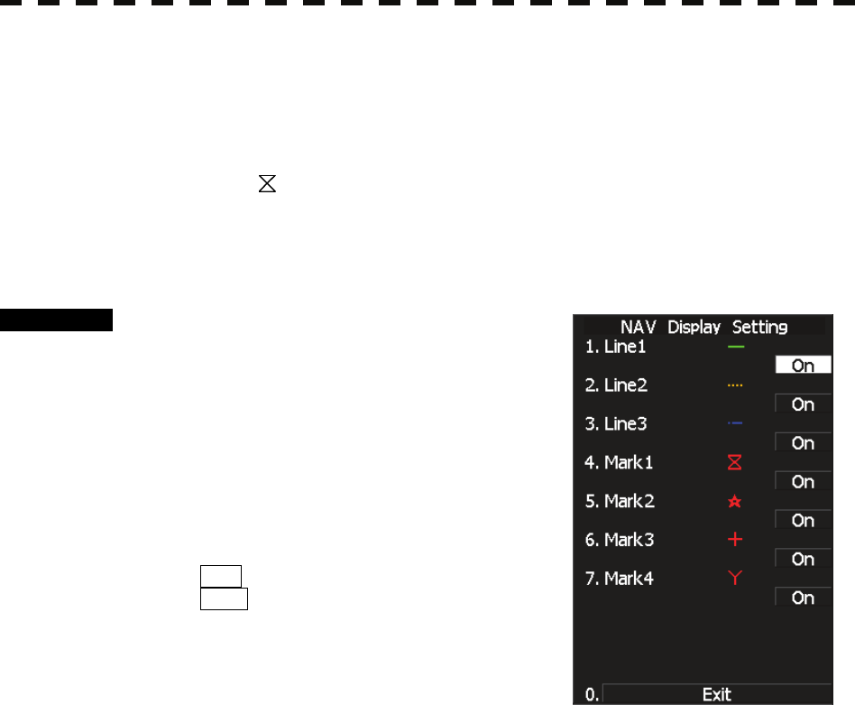
3.8.2 Display Navigation Information (NAV Display Setting)
The navigation information below can be displayed (ON) or hidden (OFF) individually.
c Line 1 [Line 1] ―
d Line 2 [Line 2] ----
e Line 3 [Line 3] ‐―
f Mark 1 [Mark 1]
g Mark 2 [Mark 2] ★
h Mark 3 [Mark 3] +
i Mark 4 [Mark 4] Y
Procedure 1 Press [RADAR MENU] key.
Press [6] key.
Press [2] key.
The NAV Display Setting Menu will appear.
To determine whether to display each type of
navigation information, press the corresponding
numeric key.
ON : Displays the navigation information.
OFF : Does not display the navigation
information.
3.8 DISPLAY NAVIGATION INFORMATION (NEW INFORMATION DISPLAY)
3─86
3
y
y y
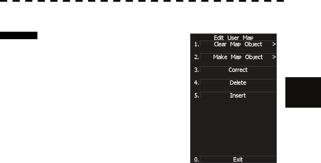
3.8.3 Create/Edit Navigation Information (Edit User Map)
Procedure 1 Press [RADAR MENU] key.
Press [6] key.
Press [3] key.
Press [6] key.
The Edit User Map Menu will appear.
The Edit User Map enables the operations of the
functions below.
Clear Map Object: Clears all or an item of
navigation information.
Make Map Object: Creates navigation
information.
Correct: Corrects navigation information.
Delete: Deletes one point from navigation
information.
Insert: Inserts an element into a line of each type
3─87
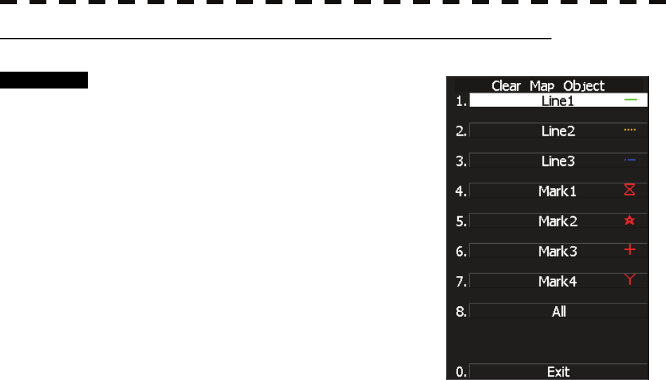
1 Clearing all or an item of navigation information (Clear Map Object)
Procedure 1 Press [1] key while the Edit User MAP
Menu is open.
The Clear Map Object Menu will appear.
Select the type of navigation information to be
cleared, pressing the corresponding numeric key.
Line1: Clears Line 1.
Line2: Clears Line 2.
Line3: Clears Line 3.
Mark1: Clears Mark 1.
Mark2: Clears Mark 2.
Mark3: Clears Mark 3.
Mark4: Clears Mark 4.
All: Clears all items of navigation information.
3.8 DISPLAY NAVIGATION INFORMATION (NEW INFORMATION DISPLAY)
3─88
3
y
y y
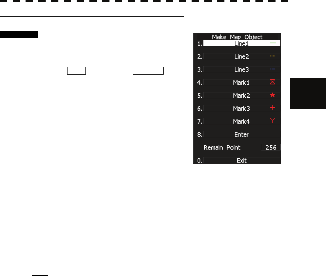
2 Making navigation information (Make Map Object)
Procedure 1 Press [2] key while the Edit User MAP
Menu is open.
The Make Map Object Menu will appear.
MAKE will appear in the CURSOR mode
field at software button ② located at the bottom
right corner of the radar display described in
Section 2.3.3.
2 Select the type of navigation
information to be made, pressing the
corresponding numeric key.
3 Use the trackball to move the cross
cursor mark to the starting point of a
line or a point where a mark is to be
made, and press [ENT] key.
The starting point of a line or one point of a mark will be determined.
4 Repeat step 3, and press [8] key when finishing the making of the line or
mark.
The line or mark make mode will terminate.
5 To make another line or mark, repeat steps 2 to 4.
6 Press [0] key when finishing the making of all navigation information.
The Edit User Map Menu will reappear.
Note: Navigation information can be created with a maximum of 256 points being plotted.
The number of points that can still be plotted (REMAIN POINT in the menu) is decremented
each time a line or mark is plotted.

3─89
3 Correcting a continuous line or moving a mark (Correct)
Procedure 1 Press [3] key while the Edit User Map
Menu is open.
The navigation information correction mode will
be activated.
Correct will appear in the CURSOR
mode field at software button ② located at the
bottom right corner of the radar display
described in Section 2.3.3.
2 Use the trackball to move the pointer to
the vertex in a line to be corrected or
the mark to be moved, and press [ENT]
key.
The cross cursor mark will appear on the
selected line or mark.
3 Use the trackball to move the cross
cursor mark to a new point to which the line is corrected or the mark is
moved.
The selected line will be corrected to the new point, or the mark will be moved there.
4 To correct another line or mark, repeat steps 2 and 3.
5 Press [0] key when finishing the correction of lines and marks.
The CURSOR mode at the upper right of the radar display will change to the general
operation mode, terminating the navigation information correction mode.
(Example)
Select a top
3.8 DISPLAY NAVIGATION INFORMATION (NEW INFORMATION DISPLAY)
3─90
3
y
y y
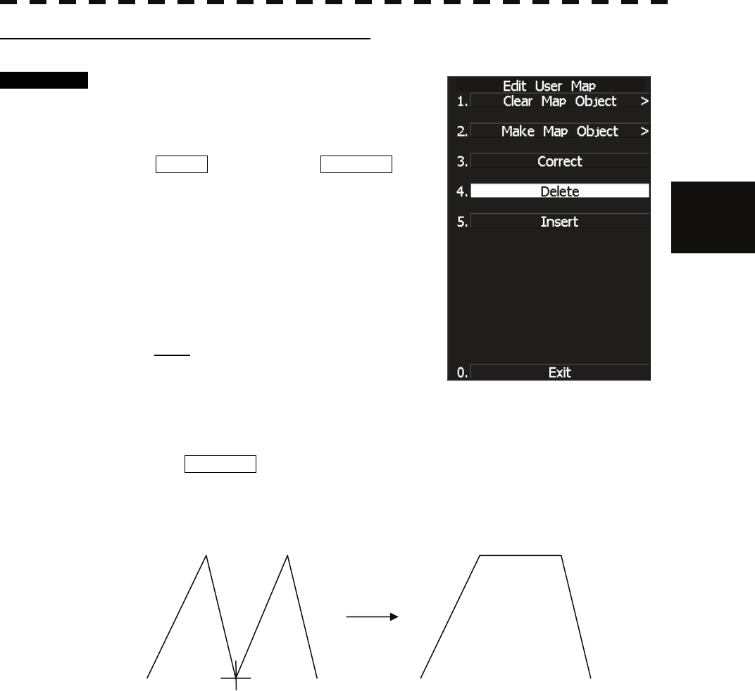
4 Deleting a continuous line or mark (Delete)
Procedure 1 Press [4] key while the Edit User Map
Menu is open.
The navigation information deletion mode will
be activated.
Delete will appear in the CURSOR mode
field at software button ② located at the top
right corner of the radar display described in
Section 2.3.3.
2 Use the trackball to move the pointer to
the vertex in a line or the mark to be
deleted, and press [ENT] key.
The selected line or mark will be deleted.
Note: A line drawn by joining two points is all
deleted.
3 To delete another line or mark, repeat step 2.
4 Press [0] key when finishing the deletion of lines and marks.
The CURSOR mode at the upper right of the radar display will change to the general
operation mode, terminating the navigation information deletion mode.
(Example) Deletion of a vertex from a line
3─91
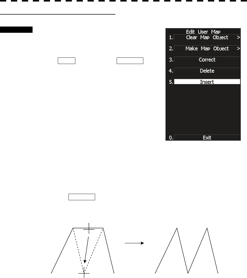
5 Inserting a vertex into a line (Insert)
Procedure 1 Press [5] key while the Edit User MAP
Menu is open.
The navigation information insertion mode will
be activated.
Insert will appear in the CURSOR mode
field at software button ② located at the top
right corner of the radar display described in
Section 2.3.3.
2 Use the trackball to move the pointer to
the line that is to become a vertex, and
press [ENT] key.
The cross cursor mark will appear on the
selected point.
3 Use the trackball to move the cross
cursor mark to a new point where a
vertex is to be formed, and press [ENT] key.
A vertex will be inserted into the selected line.
4 To insert another vertex, repeat steps 2 and 3.
5 Press [0] key when finishing the insertion of all vertices.
The CURSOR mode at the upper right of the radar display will change to the general
operation mode, terminating the navigation information insertion mode.
(Example)

3.8 DISPLAY NAVIGATION INFORMATION (NEW INFORMATION DISPLAY)
3─92
3
y
y y
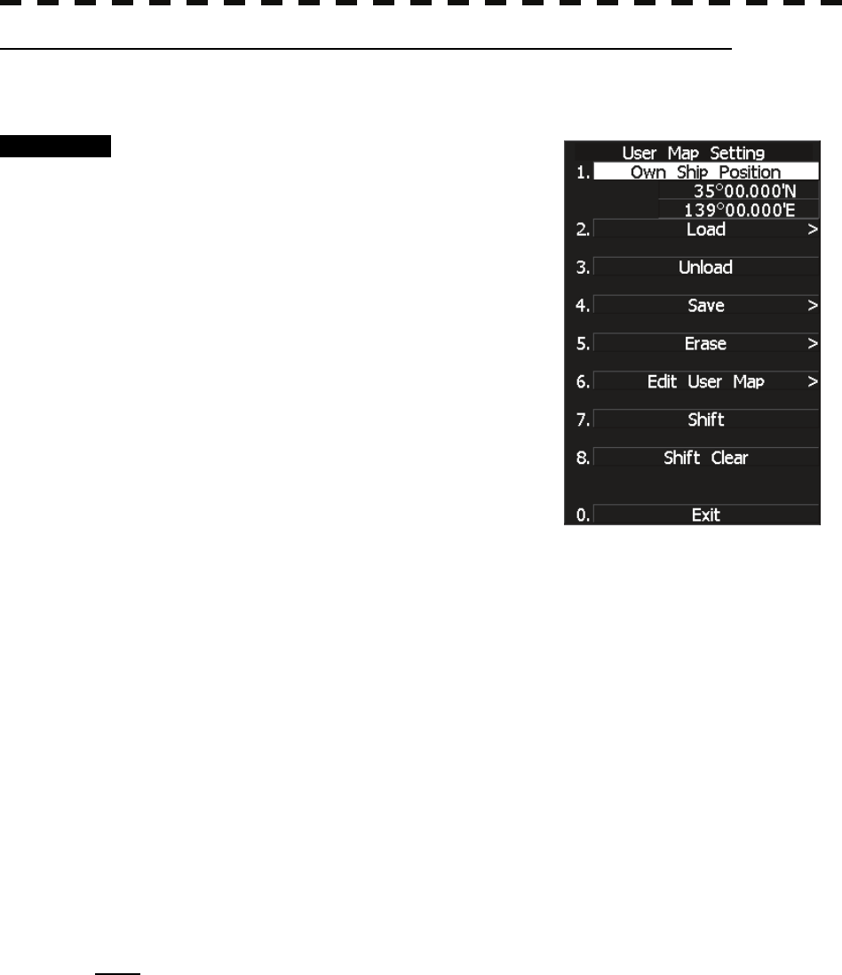
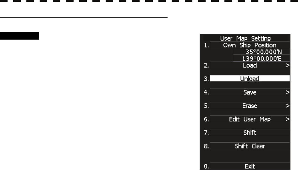
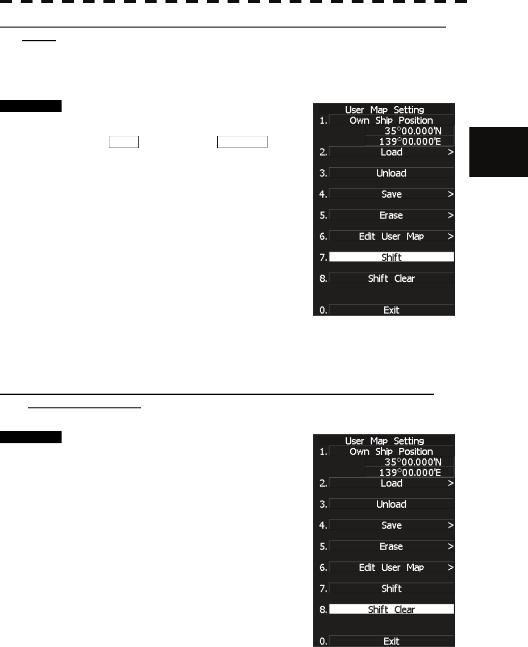
3.8.4 Set Navigation Information (User Map Setting)
Procedure 1 Press [RADAR MENU] key.
Press [6] key.
Press [3] key.
The User Map Setting Menu will appear.
Select operation for navigation information,
pressing the corresponding numeric key. The
selected operation will be performed.
Load: Loads navigation information.
Unload: Unloads navigation information.
Save: Saves navigation information.
Erase: Erases navigation information.
Edit User Map:Edits navigation information.
Shift: Shifts the display position of
navigation information.
Shift Clear: Clears position correction information.
3─93
[I] Entering the own ship’s position in manual mode (Own Ship Position)
Use this function to edit the navigation information of any positions other than the own ship’s position.
Procedure 1 Press [1] key while the User Map
Setting Menu is open.
The CODE INPUT Menu for entering latitude
and longitude of the own ship position will
appear.
2 Enter a value as the latitude (xx°
xxx.xx’) using the numeric keys [0] to
[9].
3 To switch between north latitude and
south latitude, turn the [MULTI] control.
Each time the control is turned, N (north
latitude) is changed to S (south latitude), or vice
versa.
4 Press [ENT] key.
The latitude entered in manual mode will be determined.
Subsequently, enter the longitude.
5 Enter a value as the longitude (xx° xxx.xx’) using the numeric keys [0] to
[9].
6 To switch between east longitude and west longitude, turn the [MULTI]
control.
Each time the control is turned, E (east longitude) is changed to W (west longitude), or
vice versa.
7 Press [ENT] key.
The longitude entered in manual mode will be determined.
* Button on the CODE INPUT Menu is also available instead of the numeric keys.
Note: The own ship’s position manually entered by using the function above is valid only in the User
MAP Setting Menu. When control exits from the menu, the manually entered position data is
invalidated.
3.8 DISPLAY NAVIGATION INFORMATION (NEW INFORMATION DISPLAY)
3─94
3
y
y y
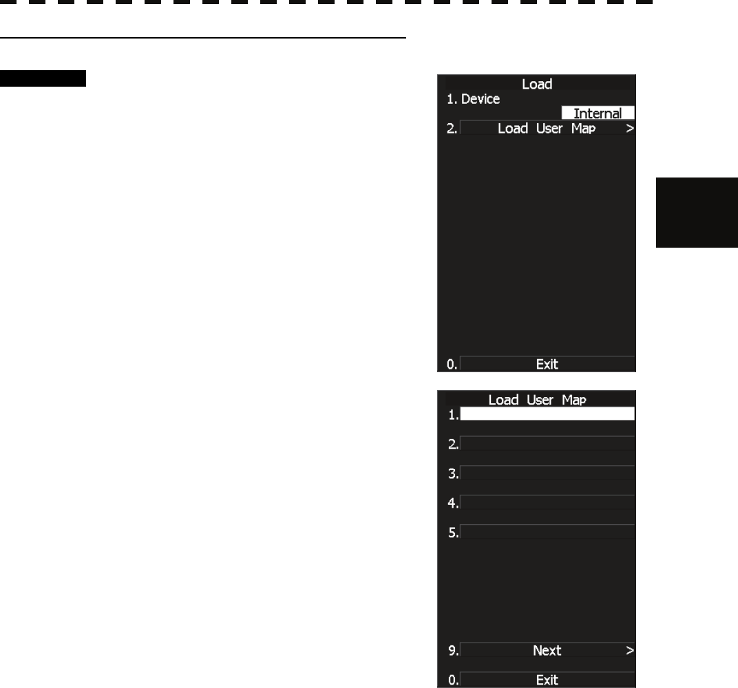
[II] Loading navigation information (Load User Map)
Procedure 1 Press [2] key while the User Map
Setting Menu is open.
The Load User Map Menu will appear.
2 Press [2] key.
The list of navigation information files saved in
the system will appear.
* Each time you press [1] key, the Device item is switched between
INTERNAL and CARD2.
INTERNAL: Reads saved data from the processor.
CARD2: Reads saved data from CARD2.
To select CARD2, insert the flash memory card, in which data has
been saved, into card slot 2 (upper stage).
3 Select the number of the file to be
loaded, pressing the numeric key.
The selected navigation information will be
loaded and shown on the radar display.
3─95
[III] Initializing Navigation Information (Unload)
Procedure 1 Press [3] key while the User Map
Setting Menu is open.
Display the window to select whether or not the
information is to be initialized.
2 Press [1] key.
The navigation information is initialized.
This function can be executed for files that have been
read and new navigation information currently being
entered.
3.8 DISPLAY NAVIGATION INFORMATION (NEW INFORMATION DISPLAY)
3─96
3
y
y y
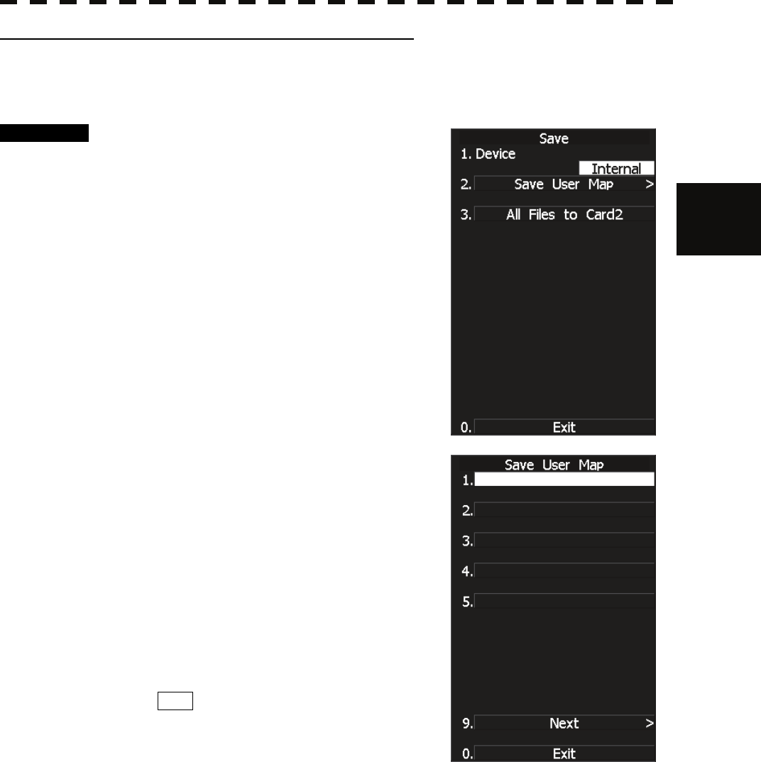
[IV] Saving navigation information (Save User Map)
This function is available only when navigation equipment is connected with the system or the own ship’s
position is entered in manual mode.
Procedure 1 Press [4] key while the User Map
Setting Menu is open.
2 Press [2] key.
The Save User Map Menu will appear.
* Each time you press [1] key, the Device item is switched between
INTERNAL and CARD2.
INTERNAL: Saves data in the processor.
CARD2: Saves data in CARD2.
To select CARD2, insert the flash memory card, in which data has
been saved, into card slot 2 (upper stage).
3 Select the number of the file to be
saved, pressing the numeric key.
The Name Input Menu will appear.
4 Use the trackball to select an
alphabetic character A-Z or 0-9 shown
in the menu and press [ENT] key on
your required characters.
A maximum of 8 characters can be entered.
5 Repeat step 4 until the file name to be
saved is created, move the cursor to
ENT , and press [ENT] key.
The currently displayed navigation information
will be saved.
3─97
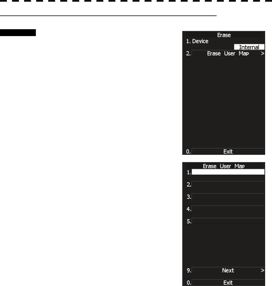
[V] Erasing navigation information from memory (Erase User Map)
Procedure 1 Press [5] key while the User Map
Setting Menu is open.
2 Press [2] key.
The Erase User Map Menu will appear.
* Each time you press [1] key, the Device item is switched between
INTERNAL and CARD2.
INTERNAL: Erases saved data from the processor.
CARD2: Erases saved data from CARD2.
To select CARD2, insert the flash memory card, in which data has
been saved, into card slot 2 (upper stage).
3 Select the number of the file you want
to erase, pressing the numeric keys [1]
to [5].
The navigation information file will be erased
from the memory, and the file name will
disappear from the file list.
3.8 DISPLAY NAVIGATION INFORMATION (NEW INFORMATION DISPLAY)
3─98
3
y
y y
[VI] Shifting the display position of navigation information to a correct position
(Shift)
If the display position of navigation information is incorrect, it can be shifted to the correct position in
manual mode.
Procedure 1 Press [7] key while the User Map
Setting Menu is open.
Shift will appear in the CURSOR mode
field of software button ② located at the top
right corner of the radar display described in
Section 2.3.3, and the navigation information
shift mode is activated.
2 Use the trackball to move the pointer to
a mark or a point on a NAV line,
coastline, or depth contour line, and
press [ENT] key.
3 Use the trackball to move the cross
cursor mark to the position to which
the mark or line is shifted, and press
[ENT] key.
All the marks and lines currently displayed will be shifted to their correct positions.
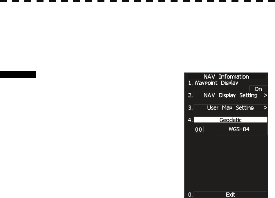
[VII] Shifting the corrected display position of navigation information back to
original (Shift Clear)
Procedure 1 Press [8] key while the User Map
Setting Menu is open.
The MAP returns to the original position.
3─99
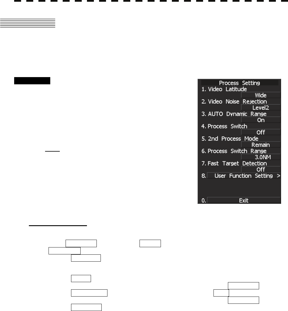
3.8.5 Set and Display Geodetic System
To create navigation information, set the geodetic system that is used with the connected navigation equipment.
When navigation information is loaded, the geodetic system used when the navigation information was saved,
is displayed. Make sure that the displayed geodetic system is identical to the one used with the navigation
equipment. If the two geodetic systems are different, the positions of navigation information on the radar
display will be shifted. Therefore, it is important to set the geodetic system of the navigation equipment.
Procedure 1 Press [RADAR MENU] key.
Press [6] key.
The NAV Information Menu will appear.
2 Press [4] key.
The geodetic system input ten-key screen will
appear.
3 Enter the number of the target geodetic
system, pressing the numeric keys.
4 The entered geodetic system number
can be changed by turning the [MULTI]
control.
5 Press [ENT] key.
The entered geodetic system will be determined.

3.8 DISPLAY NAVIGATION INFORMATION (NEW INFORMATION DISPLAY)
3─100
3
y
y y
Geodetic System List
No. Name Data Display
0 WGS-84 WGS-84
1 WGS-72 WGS-72
2 Japan Japan
3 North American 1927(U.S) NAS
4 North American 1927(Canada & Alaska) NAS
5 European 1950 (Europe) EUR
6 Australian geodetic 1966 (Australia) AUA
7 Ordance Survery of Great Britain (England) UK
8 NAD-83 NAD-83
9 - (No Use)
10 - (No Use)
11 ADINDAN (Etiopia & Sudan) ADI
12 ARC 1950 (Botswana) ARF
13 AUSTRALIAN GEODETIC 1984 (Australia) AUF
14 BERMUDA 1957 (the Bermudas) BER
15 BOGOTA OBSERVATORY (Columbia) BOO
16 CAMPO INCHAUSPE CAI
17 CHATHAM 1971 AHI
18 CHUAASTRO (Paraguay) CHU
19 CORREGO ALEGRE (Brazil) COA
20 DJAKARTA (VATAVIA) (Sumata) BAT
21 EUROPEAN 1979 (Europe) EUS
22 GEODETIC DATUM 1949 (New Zeland) GEO
23 GUAM 1963 (Guam) GUA
24 HAYFORD 1910 (Finland) HAYFORD
25 HJORSEY 1955 (Ice land) HJO
26 INDIAN (India & Nepal) IND
27 IRELAND1965 (Ireland) IRL
28 KERTAU 1948 (West Malaysia) KEA
29 L.C.5 ASTRO (Cayman Black Island) LCF
30 LIBERIA 1964 (Liberia) LIB
31 LUZON (Philippines) LUZ
32 MERCHICH (Morocco) MER
33 MINNA (Cameroon) MIN
34 NAHRWAN (Oman) NAH
35 NAPARIMA, BWI (Trinidad & Tobago) NAP
36 OLD EGYPTIAN (Egypt) OEG
37 OLD HAWAIIAN (Hawaii) OHA
38 PCO DE LAS NIEVES (Canary) PLN
39 PROVISIONAL SOUTH AMERICAN 1956 (South America) PRP
40 PROVISIONAL SOUTH CHILEAN 1963 (South Chile) HIT
41 PUERTO RICO (Puerto Rico & Virgin Islands) PUR
42 QORNOQ (South Greenland) QUO
43 RT90 (Sweden) RT90
44 SANTA BRAZ (San Miguel island & Saint Mary islands) 44
45 SOUTH AMERICAN 1969 (South America) SAN
46 SOUTHWEST BASE
(Faial & Sao Jorge & Pico & Graciosa & Terceira island)
46
47 TIMBALAI 1948 (Brunei & East Malaysia) TIL
48 - (No Use)
49 - (No Use)
3─101
3.9 APPLIED OPERATIONS
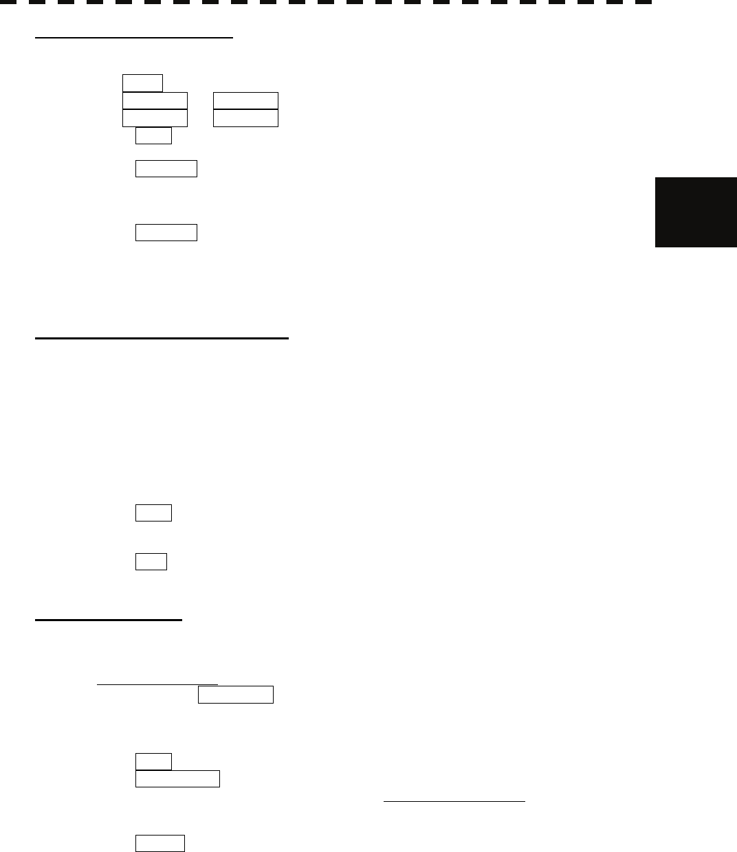
3.9.1 Set Radar Signal Processing (Process Setting)
This function enables the setting of detail information about radar signal processing.
Procedure 1 Press [RADAR MENU] key twice.
Press [6] key.
The Process Setting Menu will appear.
Detail information about radar signal processing
can be set by changing the settings of the menu
items.
Note: After the settings for radar signal processing are
changed, small targets may not be displayed or
unwanted waves may not be suppressed. Thus, do not
make a significant change in the settings.
[1] Video Latitude
• Select the dynamic range in which receiving signals are to be shown on the radar display.
• Select NORMAL in standard, and WIDE in rainy weather.
• NARROW clearly displays short-range videos when STC is used in manual mode.
NORMAL : Standard setting
The dynamic range varies depending on the actual range:
Short range > long range
WIDE : Use this mode when rainy weather intensifies unwanted waves.
The dynamic range is about twice as wide as when NORMAL is selected.
SUPER WIDE : Use this mode when rain cloud remain at WIDE mode.
The dynamic range is about twice as wide as when NORMAL is selected.
NARROW : Narrows the dynamic range at short range.
3.9 APPLIED OPERATIONS
3─102
3
y
y y
[2] Video Noise Rejection
• This function rejects signals that assumed as noise and clutter in radar videos.
• Select OFF to display radar videos like analog signals.
• Select LEVEL1 or LEVEL2 to suppress noise and clutter.
• Select LEVEL1 or LEVEL2 to superimpose-display the chart.
OFF : Turns off the noise rejection function, and displays all signals.
Targets are popped up from noise and displayed like analog signals.
LEVEL1 : Rejects the signals of definitely unwanted waves (noise and clutter).
When detection of targets or unwanted waves is not definite, the signals are
displayed.
When detection of targets is definite, the signals are displayed.
LEVEL2 : Rejects the signals of definitely unwanted waves (noise and clutter).
When detection of targets or unwanted waves is not definite, the signals are
rejected.
Only when detection of targets is definite, the signals are displayed.
[3] Auto Dynamic Range Control
• This function automatically controls the dynamic range of radar videos when the AUTO SEA (sea
clutter suppression)/AUTO RAIN (rain/snow clutter suppression) mode is used.
• When the AUTO SEA (sea clutter suppression) mode is used, this function improves sensitivity by
widening the dynamic range of only areas where sea clutter is strong, and narrowing the dynamic range
of areas where sea clutter is not detected.
• When the AUTO RAIN (rain/snow clutter suppression) mode is used, this function improves
sensitivity by widening the dynamic range of areas where sea clutter or rain/snow clutter is strong, and
narrowing the dynamic range of the other areas.
• Land videos become obscure when the AUTO RAIN clutter suppression mode is used.
OFF : Does not control the dynamic range automatically.
The dynamic range is set in the same manner as when the MANUAL SEA/RAIN
clutter suppression mode is used.
ON : Automatically controls the dynamic range. (Standard setting)
[4] Process Switch
• This function sets a specific area and switches the video process mode between the inside and outside
of the area.
• In [5] 2nd Process Mode, set the second video process mode for the area outside the boundary.
• In [2] PROCESS of Main Menu , set the first video process mode for the area inside the boundary.
• Sensitivity at a distance can be improved by suppressing near sea clutter through the correlative
process.
• There are two methods for setting an area:
OFF : Disables the Process Switching function. (Standard setting)
RANGE FIX : Sets a boundary at a constant range from the center.
Set the boundary range in [6] Process Switch Range.
The specific area turns out to be a circle with the own ship’s position as
the center.
AUTO : Automatically sets a specific area.
The area subject to many clutter returns is inside the boundary, and the
area less subject to clutter returns is outside the boundary.
3─103
[5] 2nd Process Mode
• Set the second video process mode for the outside of a specific area.
• This function is enabled when RANGE FIX or AUTO is selected in [4] Process Switching.
Video process modes
PROC OFF Correlation Off : Select this mode in general.
3 SCAN COREL Correlation Short : Select this mode when many rain/snow clutter returns
are detected.
4 SCAN COREL Correlation Medium : Select this mode to highlight targets while suppressing
sea clutter returns.
5 SCAN COREL Correlation Long : Select this mode to detect small targets hidden by sea
clutter returns.
REMAIN Afterimage Short: Select this mode when own ship yaws wildly.
PEAK HOLD Afterimage Long : Select this mode to detect small targets of which
detection probability is low.
[6] Process Switch Range
• Set the boundary range of a specific area.
• This function is enabled when RANGE FIX is selected in [4] Process Switch.
• The specific area turns out to be a circle with the own ship’s position as the center.
• The boundary range can be set in units of 0.1 nm, ranging 0.1 to 25.5 nm.
• After selecting PROC Switch Range, adjust the range using the [MULTI] control.
• When finishing the adjustment, press [ENT] key to determine the video process switching range.
[7] Fast Target Detection
• This function displays fast moving targets that are suppressed in scan-correlative process mode.
• This function is enabled when 3SCAN CORR , 4SCAN CORR , or 5SCAN CORR is selected
as the video process mode.
• If unwanted waves remain on the radar display, suppress them by using the [SEA], [RAIN], or
[GAIN] control, or adjusting the interference rejection mode.
OFF : Disables the Fast Target Detection function.
ON : Enables the Fast Target Detection function.
[8] User Function Setting
• "Radar Function Setting" is provided for always obtaining the best radar video by storing complex
radar signal processing settings in the optimum status by use, and by calling the setting in accordance
with the conditions for using the radar signal processing function. The radar signal processing
functions are factory-set for general use, and the settings can be fine adjusted through menu operation.
• For detail, refer to Section 3.10.3 “Overview of Function Operations”.
3.9 APPLIED OPERATIONS
3─104
3
y
y y
3.9.2 Set Radar Trails (RADAR Trails Setting)
This function enables the setting of detail information about radar trails processing.
Procedure 1 Press [RADAR MENU] key twice.
Press [7] key.
Alternatively, hold down the [TRAILS]
key until the menu appears.
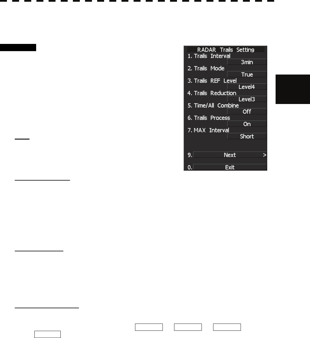
The RADAR Tails Setting Menu will appear.
Detail information about radar trails processing
can be set by changing the settings of the menu
items.
Note: After the settings for radar trails processing are changed,
targets’ trails may not be displayed or trails may be plotted
with unwanted waves. Thus, do not make a significant
change in the settings.
[1] Trails Interval
• Set the trail intervals at which radar trails are displayed.
• Selection items of trail intervals change depending on the setting of maximum value of radar trail
display time.
• The Multi-function control is also available for setting.
• For the decision branches of trail interval, see Section 3.5.10 “Display Radar Trails (Other Ships'
Trails)”.
[2] Trails Mode
• Set the radar trail display mode.
• Each time the button is pressed, you can switch between True and Relative.
• For details on the trail mode, see “Changing Motion Mode of Trails (Trails mode)” in 3.5.10 “Display
Radar Trails (Other Ships' Trails).”
[3] Trails REF Level
• Select a radar video level required for plotting radar trails.
• The radar video level increases in order of LEVEL1 → LEVEL2 → LEVEL3 →
LEVEL4 .
• To plot radar trails with unwanted waves, change to a higher level.
• To thin radar trails, change to a higher level.
• If radar trails are plotted in snatches, change to a lower level.
3─105
[4] Trails Reduction
• Make a setting for thinning radar trails.
• The effect of thinning increases in order of LEVEL1 → LEVEL2 → LEVEL3 .
• Radar videos do not become obscure because of the thinning of radar trails.
OFF : Disables the Trails Reduction function.
LEVEL1 : Enables the Trails Reduction function. (Effect: Low)
LEVEL2 : Enables the Trails Reduction function. (Effect: Modest)
LEVEL3 : Enables the Trails Reduction function. (Effect: High)
[5] Time/Cont Combine
• This function superimpose-displays time radar trails and continuous radar trails.
• Operators can distinguish time radar trails from continuous radar trails by setting different colors for
both types of trails.
OFF : Disables the Time/Cont Combine function.
ON : Enables the Time/Cont Combine function.
[6] Trails Process
• Determine whether to use the video process with radar signals for plotting radar trails.
• When Trails Process is ON , radar trails are never plotted with unwanted waves, but the radar trails
of fast moving targets may not be plotted.
• When Trails Process is OFF , radar trails may be plotted with unwanted waves, but the radar trails of
fast moving targets are always plotted.
OFF : Disables the Trails Process function.
ON : Enables the Trails Process function.
[7] MAX Interval
• Select the maximum time for displaying radar trails.
• Select Short when short radar trails are often used in bays and the likes.
• Select Super Long when long radar trails are necessary for ocean navigation.
• Medium is for specification between Short and Long .
• Continuous trails are available with all the options.
Short : Sets 15 minutes as the maximum time for radar trails display.
Medium : Sets 30 minutes as the maximum time for radar trails display.
Long : Sets 60 minutes as the maximum time for radar trails display.
Super Long : Sets 12 hours as the maximum time for radar trails display.
[9] NEXT
• The file menu will appear.
3.9 APPLIED OPERATIONS
3─106
3
y
y y
Load and save of the Rdar trails.
Procedure 1 Press [RADAR MENU] key twice.
Press [7] key.
Alternatively, hold down the [TRAILS]
key until the menu appears.
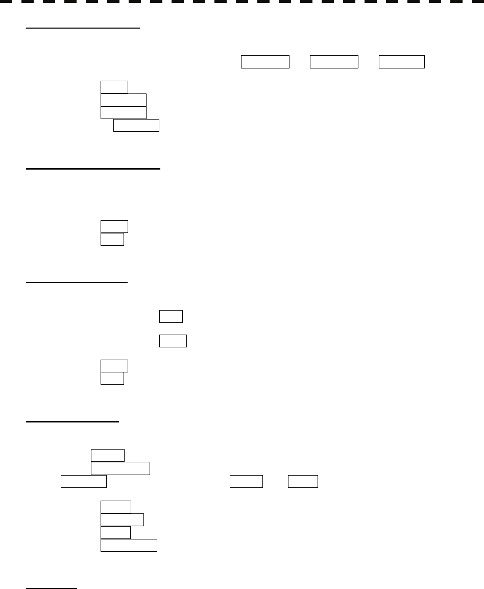
Press [9] key.
The RADAR Tails Setting Menu will appear.
[1] Loading Trails File
• Presse [1] key.
The saved trail files are displayed.
• Select the file to be loaded
Confirmation warining is displayed.
Select “Yes” for loading.
It takes a few second to be loded.
Note: When the saved trail position is too far from own ship position, the saved trails can not be
loaded.
On the standby mode, however, far trail positions can be loaded. In that case, the own ship
position is changed to the loaded trail position temporally.
After loading, Range scale, Trails mode (True / Relative) and Max interval are set to loded
settings.
[2] Saving Trails File
• Presse [2] key.
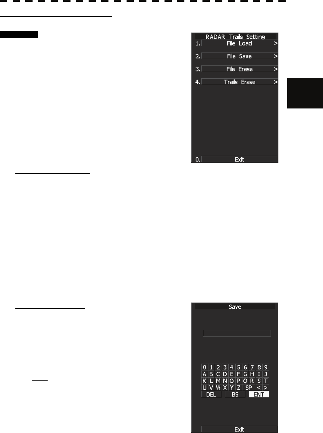
The File Save menu is displayed.
• Using the cusor, enter the file name and click “ENT”
Confirmation warining is displayed.
Select “Yes” for saving.
It takes a few second to be loded.
Note: When the own ship position data are not available,
trails can not be saved.
3─107
[3] Erasing Trails File
• Presse [3] key.
The saved trail files are displayed.
• Select the file to be erased.
Confirmation warining is displayed.
Select “Yes” for erasing.
Note: Deleted files can not be restored, so Erase files carefully.
Erasing the displayed trails partially.
Erasing the part of the displayed trails by using the cursor as a eraser.
Note: Deleted trails can not be restored, so Erase them carefully.
Procedure 1 Press [RADAR MENU] key twice.
Press [7] key.
Alternatively, hold down the [TRAILS]
key until the menu appears.
Press [9] key.
Press [4] key.
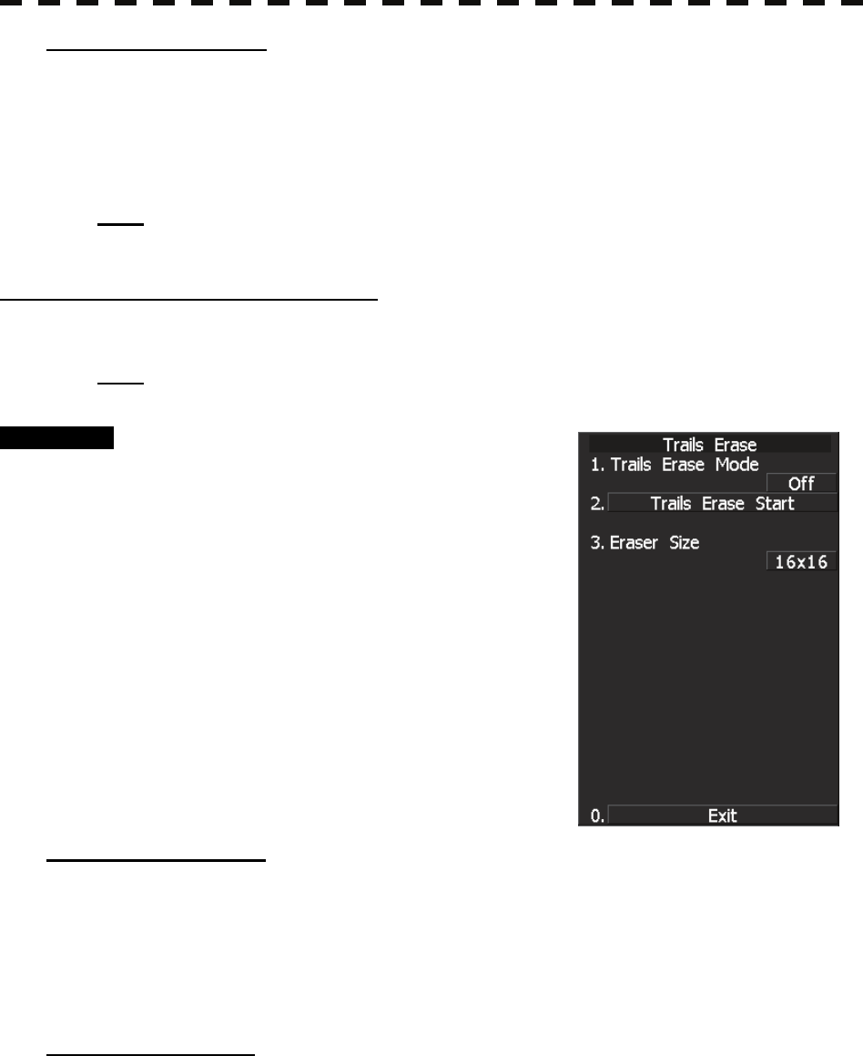
Trail erase menu will appear.
[1] Trails Erase Mode
Press [1] key.
z Trail erase mode is enabled.
z On the mode, cusor is fixed on the menu, and the eraser (white box) is displayed on
the own ship positon.
z Using the trackball, positon the eraser on the Trail to be deleted.
[2] Trails Erase start
Press [2] key.
z Trail erase function starts.
Using the track ball, wipe out trails.
z Press [2] key again to disable the function temporally.
The depth input scre

3.9 APPLIED OPERATIONS
3─108
3
y
y y
[3] Eraser Size
Press [3] key.
z Eraser size lit is displayed.
z Select the size of the eraser.
2x2 : 2x2 pixels
4x4 : 4x4 pixels
8x8 : 8x8 pixels
16x16 : 16x16 pixels
32x32 : 32x32 pixels
3─109
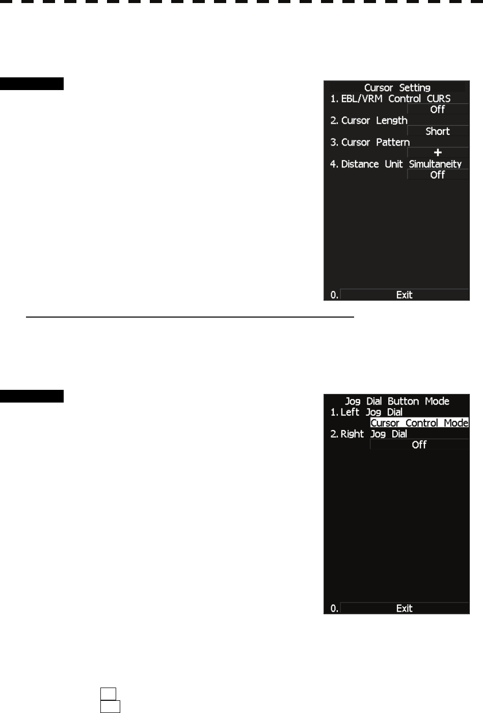
3.9.3 Set Cursor (Cursor Setting)
This function enables the setting of detail information about cursor operation and display.
Procedure 1 Press [RADAR MENU] key.
Press [3] key.
Press [6] key.
The Cursor Setting Menu will appear.
Detail information about cursor operation and
display can be set by changing the settings of the
menu items.
[1] EBL/VRM Control CURS (device for cursor operation)
• This function is switched between ON and OFF of EBL/VRM Control CRUS function
• The trackball is provided as a standard device. If the trackball malfunctions, the cursor can be moved
by using the [EBL] control and [VRM] control.
• Set the cursor control mode as the Jog Dial mode.
Procedure 1 Hold down the [EBL] control for two
seconds.
Press [1] key.
The Left Jog Dial will open. Select Cursor
Control Mode.
• The cursor moves horizontally when [EBL] is operated, and moves vertically when [VRM] is
operated.
• To switch between EBL/VRM operation and cursor operation while ON is selected, press the [EBL]
control. Each time the [EBL] control is pressed, EBL/VRM operation is switched to cursor operation,
or vice versa.
ON: Cursor is operated using a [EBL] [VRM] control.
OFF: Cursor is operated using a trackball.
3.9 APPLIED OPERATIONS
3─110
3
y
y y
[2] Cursor Length
• Set the length of the cross cursor mark on the radar display.
SHORT : Cuts the cross cursor mark in length.
LONG : Makes the cross cursor mark twice as long as when SHORT is selected.
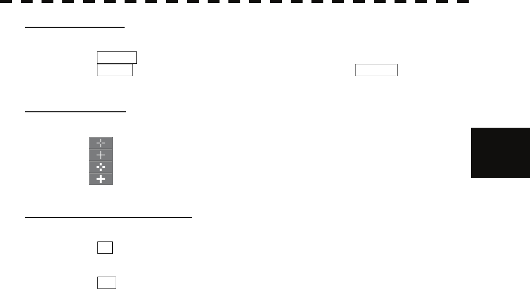
[3] Cursor Pattern
• The type of the cross cursor mark displayed of the display is selected.
: Type 1 is selected for the cross cursor mark 1 displayed in the radar display.
: Type 2 is selected for the cross cursor mark 2 displayed in the radar display.
: Type 3 is selected for the cross cursor mark 1 displayed in the radar display.
: Type 4 is selected for the cross cursor mark 2 displayed in the radar display.
[4] Distance Unit Simultaneity
• Synchronizes the cursor range unit with the VRM1/VRM2 range unit.
ON: The range units are synchronized between the cursor and VRM1/VRM2. A range
unit cannot be selected individually for the cursor or VRM1/VRM2, and the same
range unit is selected for all of them.
OFF: The range units are not synchronized between the cursor and VRM1/VRM2. A
range unit can be selected individually for the cursor and VRM1/VRM2.
3─111
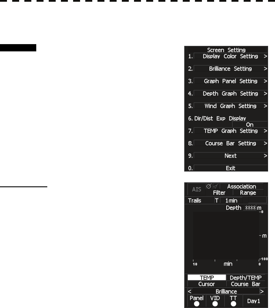
3.9.4 Set Screen(Screen Setting)
This function enables the setting of detail information about screen display.
Procedure 1 Press [RADAR MENU] key.
Press [4] key.
The Screen Setting Menu will appear.
Detail information about screen display can be
set by changing the settings of the menu items.
Graph Display
Press the graph button to see the registered graph.
To register a graph, hold down the graph button or
use Graph Panel Setting menu described on the next
page.
3.9 APPLIED OPERATIONS
3─112
3
y
y y
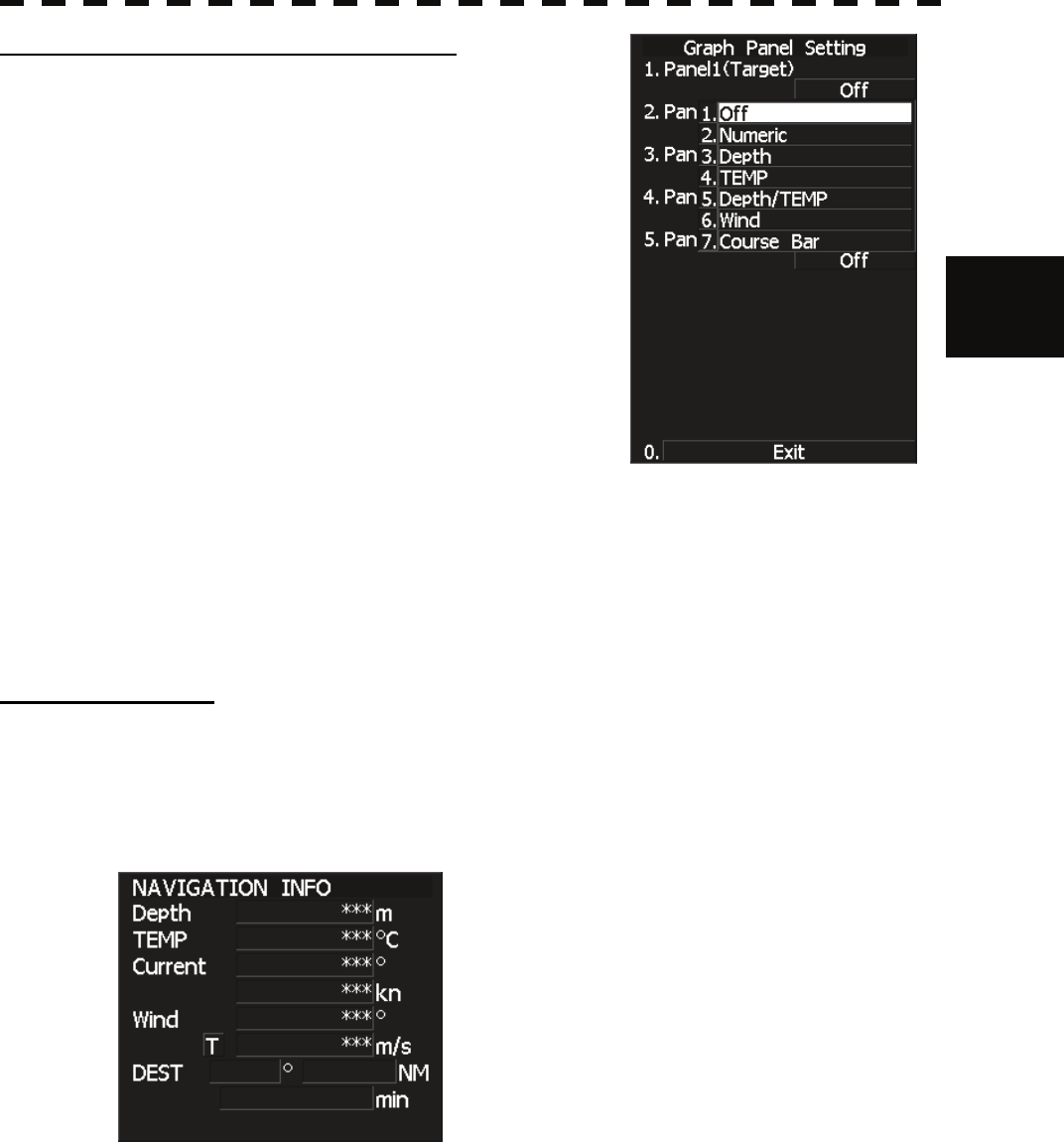
[3] Graph Settings (Graph Panel Setting)
Set the functions of a graph to be associated with the
graph button.
The function shown in the parentheses is prioritized.
Therefore, specify a graph to be displayed while the
prioritized function is not active.
1. Panel 1 (Target):
A graph registered here can be displayed while
target information is not displayed.
2. Panel 2 (Marker):
A graph registered here can be displayed while
the marker function is not in use.
3. Panel 3 (Waypoint):
A graph registered here can be displayed while
destination information is not displayed.
4. Panel 4 (Cursor/EBL/VRM):
A graph registered here can be displayed while
the cursor/EBL/VRM zoom display function is not in use.
5. Panel 5 (Graph):
A graph registered here can be displayed since there are no priority functions to be
displayed.
(*) When using a regular graph, first register it in Panel 5 menu.
Numeric NAV INFO
• Select numerical information (Numeric) in graph setting menu to register the Numeric function with
the graph button.
• Press the Numeric button to see received navigation information in numerical values.
• Water depth, water temperature, current, wind direction, wind speed, and destination are shown in
numerical values.
3─113
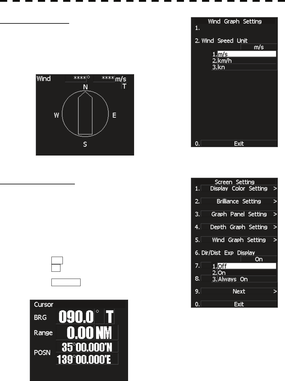
Wind/Current Graph
• The wind direction and speed display function (Wind) is
registered with the graph button when "Wind" is selected in
the graph setting menu.
• Press the Wind button to call up numerical values and a graph
for the received wind direction and speed information.
DIR/DIST EXP Display
• Cursor, EBL, and VRM values are displayed in a larger font.
• While the cursor is moving within the PPI screen, the cursor
information is displayed in a larger font.
• When EBL and VRM are used, values for each marker are
displayed in a larger font.
• Information will not be displayed in a larger font while menu
is displayed.
Direction and distance zoom display setting
OFF : No zoom display.
ON : Zoom display continues for 5 seconds
after marker operations end.
Always:ON : Information is always displayed in a
larger font.
3.9 APPLIED OPERATIONS
3─114
3
y
y y
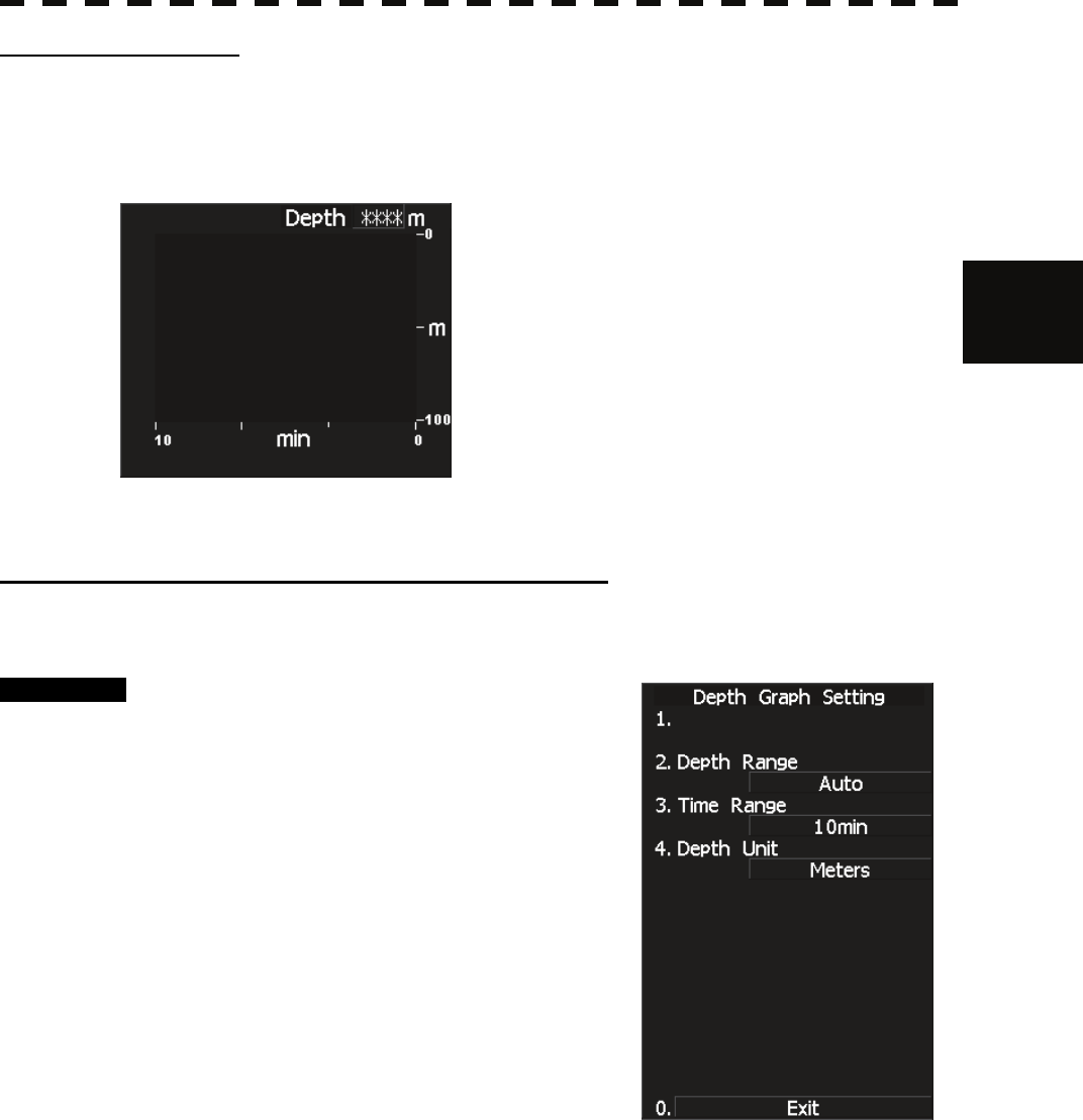
Depth Graph Display
• The water depth display function (Depth) is registered with the graph button when "Depth" is selected
in the graph setting menu.
• Press the Depth button to call up numerical values and a graph for the received water depth
information.
Displaying Water Depth Graph (Depth Graph Setting)
• Set the water depth graph display method.
Procedure 1 Press [RADAR MENU] key.
Press [4] key.
Press [4] key.
The Depth Graph Setting Menu will appear.
Detail information about screen display can be
set by changing the settings of the menu items.
3─115
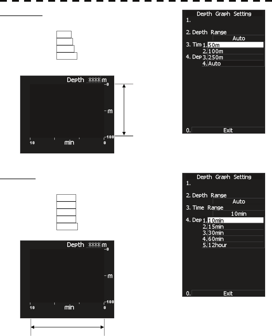
Depth Range
• Select the depth range on the water depth graph.
50m : Sets 50 m as the depth range.
100m : Sets 100 m as the depth range.
250m : Sets 250 m as the depth range.
AUTO : Uses the depth range in the DPT
sentence included in received data.
Time Table
• Select the time range on the water depth graph.
10min : Sets 10 minutes as the time range.
15min : Sets 15 minutes as the time range.
30min : Sets 30 minutes as the time range.
60min : Sets 60 minutes as the time range.
12hour : Sets 12 hours as the time range.
Depth range
Time range
3.9 APPLIED OPERATIONS
3─116
3
y
y y
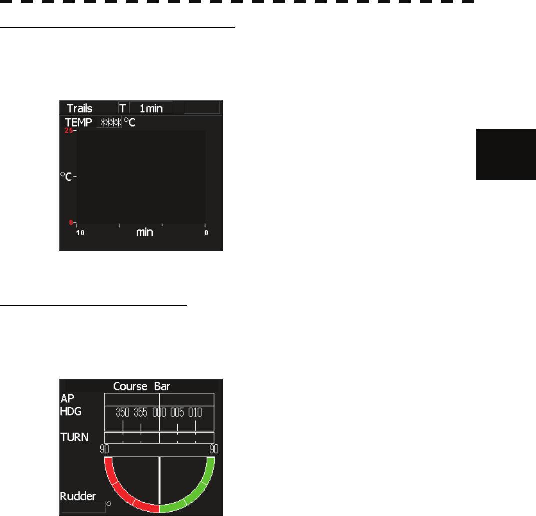
Water Temperature Display (Temp Graph)
• The water temperature display function (Temp) is registered with the graph button when "Temp" is
selected in the graph setting menu.
• Press the Temp button to call up numerical values and a graph for the received water temperature
information.
Course Bar Display (Course Bar)
• The course bar display function (Course Bar) is registered with the graph button when "Course Bar" is
selected in the graph setting menu.
• Press the Course Bar button to call up numerical values and a graph for the received heading, turning
ratio, and steering direction information.
3─117
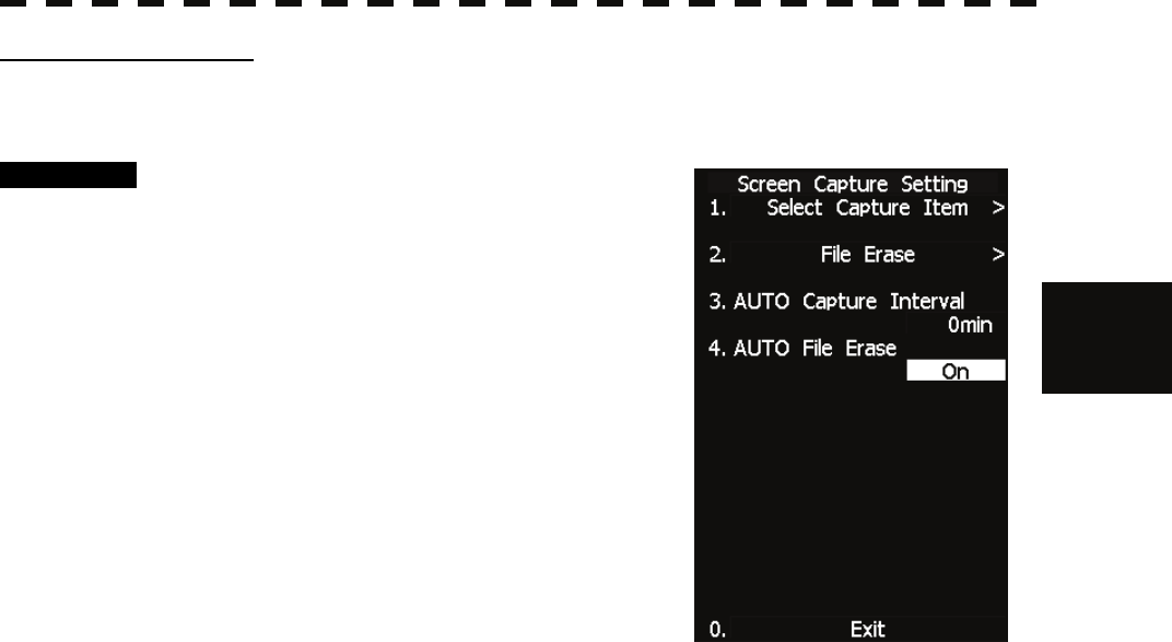
Screen Capture Setting
• This equipment can save the currently displayed images onto a memory card (CF card) while they are
in bitmap format.
• In order to execute this item, a memory card (optional) must be inserted in the card slot 2 (upper slot)
beforehand.
• For use of a CF card, see Section 3.11 "USING CARD."
Note: Once captured images have been saved, this equipment cannot display them.
To display or check a captured image which has been saved, import the capture-image file from
the CF card into the PC, and then operate the file on the PC.
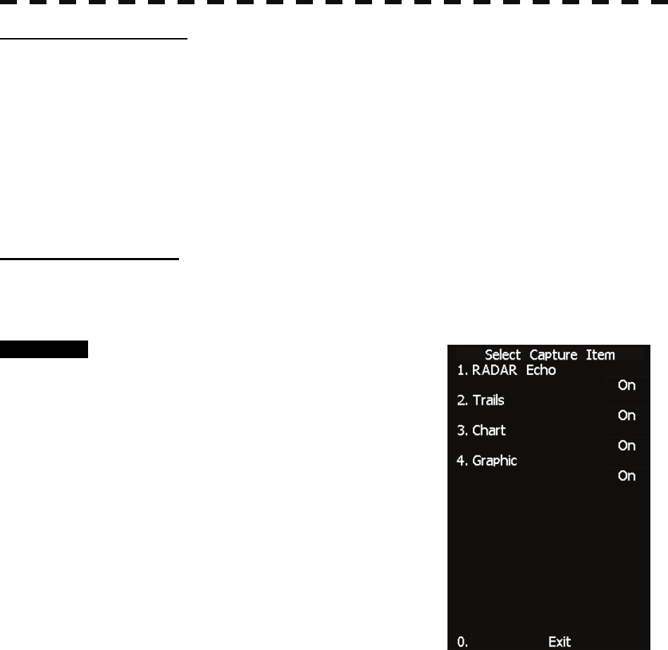
[I] Select Capture Item
Select the information to be saved as a captured image when performing the screen capture function.
Set a value in accordance with the information to be captured on the display.
Procedure 1 Press [RADAR MENU] key.
Press [4] key.
Press [9] key.
Press [1] key.
The Screen Capture Setting menu will appear.
2 Press [1] key.
The Select Capture Item menu will appear.
Details about the display capture function can be
set by changing item settings.
Radar Echo The radar echoes will be saved.
Trails The radar trails will be saved.
Chart The chart, mark, line, own ship’s track, target track, route, destination and
NAV line will be saved.
Graphic The radar graphic (EBL, VRM) and characters will be saved.
3.9 APPLIED OPERATIONS
3─118
3
y
y y
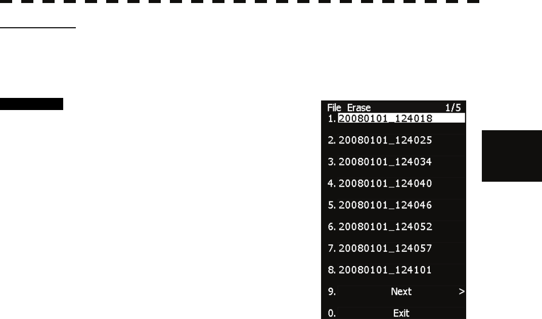
[II] File Erase
Screen capture files can be deleted.
If the CF card is full, screen capture files which are no longer necessary can be deleted by specifying the
file name (date and time).
Procedure 1 Press [RADAR MENU] key.
Press [4] key.
Press [9] key.
Press [1] key.
The Screen Capture Setting menu will appear.
2 Press [2] key.
The File Erase menu will appear.
Screen capture files are displayed in date and
time order, so select the file to be deleted and
press the [ENT] key.
The deletion confirmation screen will appear.
To delete the file, press the [1] key according to the displayed instructions.
To cancel the deletion, press the [2] key. The file deletion operation will be cancelled.
3─119
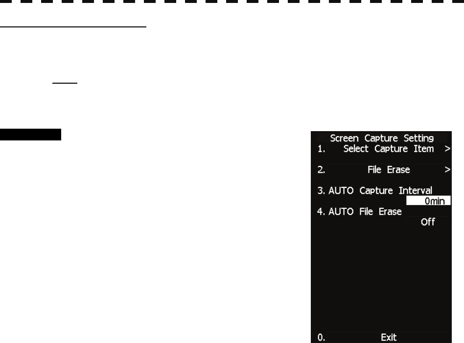
[III] AUTO Capture Interval
This function automatically saves a screen capture file at specified time intervals.
Time intervals can be specified in minutes.
Note: The use of the automatic capture function applies a high load to the CPU. As a result,
processing is always slow, so use the automatic capture function only when needed.
If the function is to be used, the allowable maximum value should be set.
Procedure 1 Press [RADAR MENU] key.
Press [4] key.
Press [9] key.
Press [1] key.
The Screen Capture Setting menu will appear.
2 Press [3] key.
The AUTO Capture Interval menu will appear.
The screen capture file is saved at specified time
intervals in minutes.
When 0 min is specified, the automatic capture
function is turned off.
When 1 min or more is specified, the automatic
capture function is turned on and performed at the specified time intervals.
3.9 APPLIED OPERATIONS
3─120
3
y
y y
[IV] AUTO File Erase
When a CF card is full with screen capture files saved, this function automatically erases files, starting
with the oldest one.
Procedure 1 Press [RADAR MENU] key.
Press [4] key.
Press [9] key.
Press [1] key.
The Screen Capture Setting menu will appear.
2 Press [4] key.
The AUTO File Erase menu will appear.
AUTO File Erase = Off, the system continues to
capture images until the CF card becomes full.
Select this item when you do not want to erase
captured images that have been saved.
AUTO File Erase = On, the system erases the oldest file so as to save a new screen
capture file when the CF card becomes full.
Select this item when you want to always save the latest captured-image data while old
files are not necessary.
This function is initially set to Off.
3─121
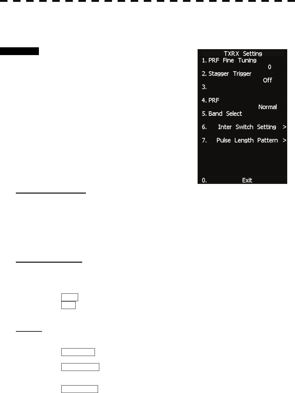
3.9.5 Set Scanner (TXRX Setting)
This function enables the setting of detail information about a scanner
Procedure 1 Press [RADAR MENU] key.
Press [5] key.
The TXRX Setting Menu will appear.
Detail information about antenna operation can
be set by changing the settings of the menu
items.
[1] PRF Fine Tuning
• Fine-tune the transmitting repetition frequency of the transmitter in the range 90 to 100%.
• If radar’s interference patterns are concentrically displayed, increment or decrement the set value by 3
to 4 in order to heighten the effect of interference rejection.
• The same operation can be performed by pressing the [TX/STBY] key several times.
• One of 32 levels 0-31 can be set.
[2] Stagger Trigger
• The interference reduction function is activated by using the transmission repetition frequency control
of the transmitter.
• This function is effective when radar interference does not go away.
OFF : Stagger Trigger is not used.
ON : Stagger Trigger is used.
[4] PRF
• Select the operation mode the transmitting repetition frequency of the transmitter.
NORMAL Standard mode: Both appropriate sensitivity and magnetron’s life
expectancy are maintained.
ECONOMY Power saving mode: Sensitivity slightly lowers, but the service life of
magnetron is prolonged when short pulses are
used.
HI POWER High sensitivity mode: Sensitivity improves when long pulses are used,
but the service life of magnetron is slightly
shortened.

3.9 APPLIED OPERATIONS
3─122
3
y
y y
[5] Band Select
• Select band of antenna. This item is effective only when the antenna in connection supports two
frequencies.
X-Band : Selects the X-band side from the two frequencies.
S-Band : Selects the S-band side from the two frequencies.
X/S-band : Supports the two frequencies.
Note: This function is not functioning now. The function is for future use.
[6] Inter Switch Setting
• The master and slave antennas are switched by the simplified interswitch function.
master : Images are displayed with the antenna connected to the display unit.
The antenna connected can be controlled.
slave : The signal of the antenna connected to another display unit is obtained via the
display unit and used to display the image.
The antenna connected to another display unit cannot be controlled.
Note: The simplified interswitch cannot control the antenna of another display unit.
Only the master antenna can be controlled.
[7] Pulse Length Pattern
• Up to 3 pulses can be selected as a pulse width in a range. Select a pulse width in combination of the
three pulses.
(Example) With a 3 NM range:
Select a combination of pulses as a desired pulse width from the following three patterns:
SP1/MP1/MP2
SP1/MP1/LP1
MP1/MP2/LP1
3─123
3.9.6 Set Chart Display (Map Setting)
This function enables the setting of detail information about chart display.
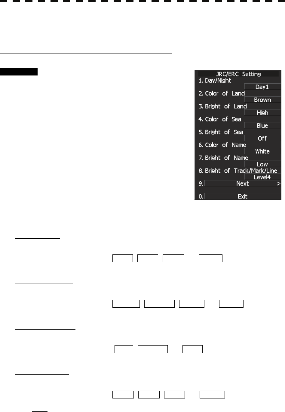
Setting JRC/ERC Chart Display (JRC/ERC Setting)
Procedure 1 Press [RADAR MENU] key.
Press [9] key.
Press [5] key.
Or, hold down the [Map] key.
Sea chart menu (Map Setting) opens.
2 Press [3] key.
The JRC/ERC Setting Menu will appear.
Detail information about the colors and brilliance
of JRC/ERC chart display can be set by changing
the settings of the menu items.
The data of colors and brilliance can be stored for
each day/night mode.
[1] Day/Night
• Select a desired display mode before setting the colors and brilliance of chart display.
• There are four selection items: DAY1 , DAY2 , DUSK , and NIGHT .
[2] Color of Land
• Select the color of land display.
• There are four selection items: BROWN , YELLOW , GREEN , and WHITE .
[3] Bright of Land
• Select the brilliance of land display.
• There are three selection items: LOW , MEDIUM , and HIGH .
[4] Color of Sea
• Select the color of sea display.
• There are four selection items: GRAY , CYAN , BLUE , and GREEN .
Note: This function is available on the plotter mode only.
3.9 APPLIED OPERATIONS
3─124
3
y
y y
[5] Bright of Sea
• Select the brilliance of sea display.
• There are four selection items: OFF , LOW , MEDIUM , and HIGH .
Note: This function is available on the plotter mode only.
[6] Color of Name
• Select the color of a location name.
• There are eight selection items: BLACK , WHITE , CYAN , BLUE , GREEN ,
YELLOW , PINK , and RED .
[7] Bright of Name
• Select the brilliance of location name display.
• There are four selection items: OFF , LOW , MEDIUM , and HIGH .
[8] Bright of Track/Mark/Line
• Select the brilliance of track, mark and line..
• There are four selection items: LEVEL1 , LEVEL2 , LEVEL3 , and LEVEL4 .
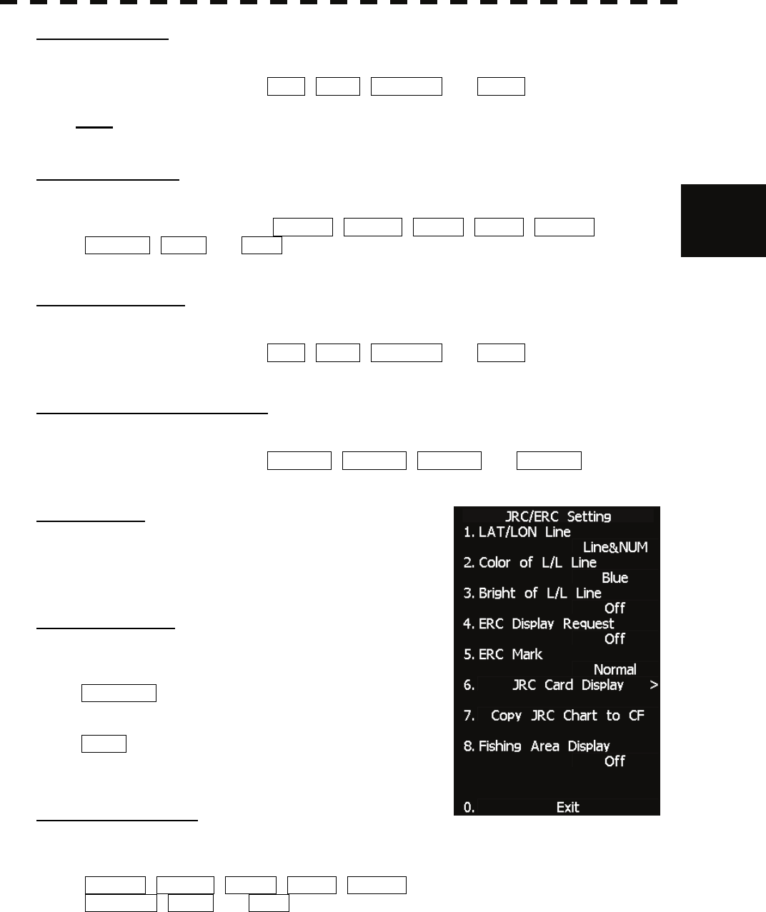
[9] Next Page
• Moves to the next page.
• The next page of the JRC/ERC Setting Menu will appear.
[1] LAT/LON Line
• Select the mode to display latitude and longitude lines.
• There are two selection items:
Line NUM : Displays both latitude/longitude lines and
values indicating the latitude and
longitude.
NUM : Displays only the values indicating the
latitude and longitude.
[2] Color of L/L Line
• Select the colors that are to represent latitude and longitude lines.
• There are eight selection items:
BLACK , WHITE , CYAN , BLUE , GREEN ,
YELLOW , PINK , and RED .
3─125
[3] Bright of L/L Line
• Select the brilliance of latitude/longitude line display.
• There are four selection items: OFF , LOW , MEDIUM , and HIGH .
[4] ERC Display Request
• Display of the information within ERC can be switched between ON and OFF .
• There are two selection items: ON , and OFF .
On : Data in the ERC is displayed.
Off : Data in the ERC is not displayed.
[5] ERC Mark
• Select the size of mark display on the ERC chart.
• There are two slection items: NORMAL and SMALL .
Normal : The ERC mark is displayed in normal size.
Small : The ERC mark is displayed in a size smaller than normal.
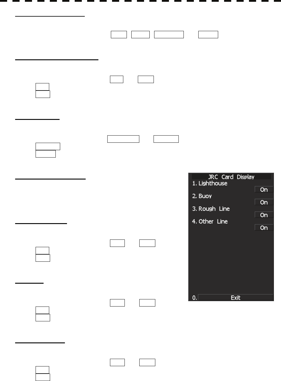
[6] JRC Card Display
• Sets the display contents of the JRC card.
• The JRC Card Display Setting Menu will appear.
[1] Light House
• Determine whether to display lighthouses.
• There are two selection items: ON and OFF .
On : Light houses are displayed.
Off : Light houses are not displayed.
[2] Buoy
• Determine whether to display buoys.
• There are two selection items: ON and OFF .
On : Buoys are displayed.
Off : Buoys are not displayed.
[3] Rough Line
• Determine whether to display rough lines.
• There are two selection items: ON and OFF .
On : Rough lines are displayed.
Off : Rough lines are not displayed.

3.9 APPLIED OPERATIONS
3─126
3
y
y y
[4] Other Line
• Determine whether to display other lines.
• There are two selection items: ON and OFF .
On : Other lines are displayed.
Off : Other lines are not displayed.
[7] Copy JRC Chart to CF
By copying multiple JRC coastline ROM cards onto a compact flash memory card, this function
selectively displays any two charts among the copied charts. For a ship that sails in the wide range, this
function is convenient because charts can be selected from the menu without alternately inserting JRC
coastline ROM cards.
Note: The copied chart can operate only in the system that originally copied the chart.
The copied chart cannot be operated in other systems. The capacity of the compact flash memory
card to be used is 2GB or less.
Procedures 1 Insert a JRC coastline ROM card into card slot 1 (lower) and insert a
compact flash memory card into card slot 2 (upper).
Flash memory card (option) is necessary.
A PCMCIA (PC card) adapter for the compact flash memory card is necessary to insert a
compact flash memory card.
For the insertion and removal of the card, see HOW TO INSERT AND REMOVE A
CARD in the appendix.
2 Press the [Map] key for 2 seconds.
Press [3] key.
Press [9] key.
3 Press the [7] key.
Confirmation Window will appear.
4 Press the [1] key.
Data on the JRC card will be copied onto the compact flash memory card.
5 To copy multiple JRC charts, alternately change JRC coastline ROM
cards and repeat procedures 4 and 5.
3─127
[8] Fishing Area Display
• If a fishery card is used but the fishery is not displayed, this setting gives priority to the fishery card.
On : Select this item if the fishery card is inserted in the card slot but the fishery is not displayed.
The fishery is displayed by giving priority to the fishery card over other cards.
Off : Select this item if the fishery card is not to be used. If the fishery card is used but the
fishery is displayed, the setting can be left off.
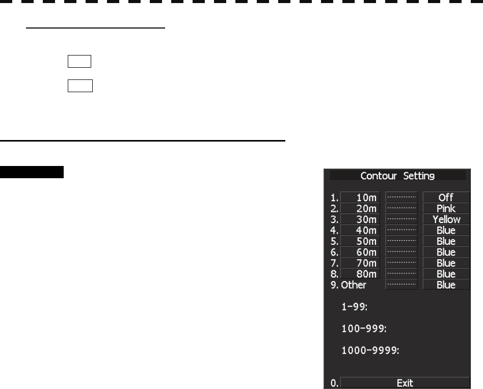
Setting Contour Lines on Chart (Contour Setting)
Procedure 1 Press [RADAR MENU] key.
Press [9] key.
Press [5] key.
Or, hold down the [Map] key.
Sea chart menu (Map Setting) opens.
2 Press [4] key.
JRC depth contour display menu (Contour
Setting) opens.
Depths and display colors can be set for 9
contour lines in total: 8 for depth specification
and 1 for other depths.
3 Select the number of depth to be changed, pressing the numeric key.
The depth input screen will appear. Enter the value as the depth to be set.
Subsequently, the display line list will appear.
4 Select the number to be set, pressing the numeric key.
The selected color to represent the contour lines of the depth will be set.
To change the settings of other depths, repeat steps 3 and 4.
3.9 APPLIED OPERATIONS
3─128
3
y
y y
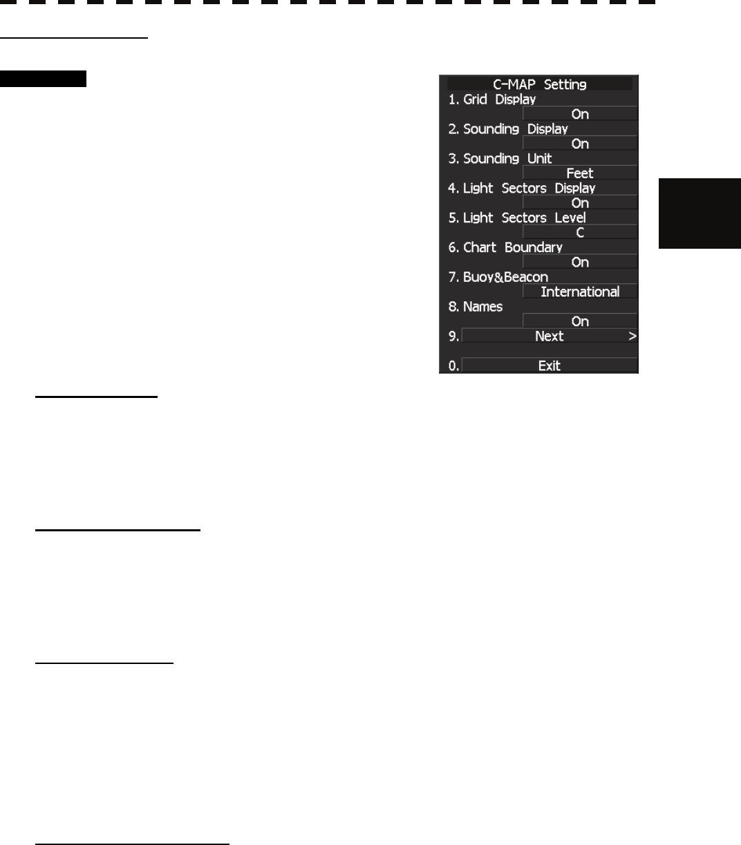
Set C-MAP Display
Procedure 1 Press [RADAR MENU] key.
Press [9] key.
Press [5] key.
Or, hold down the [Map] key.
The MAP Setting Menu will appear.
3 Press [2] key.
The C-MAP Setting Menu will appear.
[1] Grid Display
• Sets whether or not latitudinal longitudinal lines are displayed with C-MAP.
• Each time you press [1] key, the grid display item is switched between ON and OFF.
• ON: Displayed
OFF: Not displayed
[2] Sounding Display
• Sets whether or not soundings values are displayed with C-MAP.
• Each time you press [2] key, the souding display item is switched between ON and OFF.
• ON: Displayed
OFF: Not displayed
[3] Sounding Unit
• Sets the units when soundings values are displayed with C-MAP.
• Press [3] key to display a list of units.
• 1: FEET
2: FATHOM
3: METERS
You can select one from the above three items. Select the item you want to set, pressing the numeric keys
[1] to [3].
[4] Light Sectors Display
• Sets whether or not the light sectors are displayed.
• Each time you press [4] key, the light sectors display item is switched between ON and OFF.
• ON: Displayed
OFF: Not displayed

3─129
[5] Light Sectors Level
• Sets levels when light sectors are displayed with C-MAP.
• Press [5] key to display a list of levels.
• Selects one from level settings A to H.
[6] Chart Boundaries
• Sets whether or not the Chart Boundaries are displayed.
• Each time you press [6] key, the function is switched between ON and OFF.
• ON: Displayed
OFF: Not displayed
[7] Buoy and Beacon
• Sets display style of the buoy and beacon.
• Press [7] key to display a list of display style.
1: OFF
2: INTER NATIONAL : The style based on the official paper chart presentation.
3:United States : The style based on the NOAA paper chart.
4: SIMPLIFIED : Simplified style display.
[8] Geographical Names
• Sets whether or not the geographical names are displayed.
• Each time you press [8] key, the geographical name is switched between ON and OFF.
• ON: Displayed
OFF: Not displayed
[9] NEXT
• Going to Next page.
• Another C-MAP setting menu is displayed..
3.9 APPLIED OPERATIONS
3─130
3
y
y y
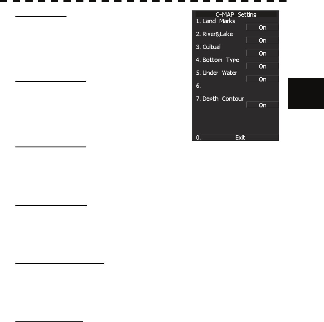
[1] Land Marks
• Sets whether or not the Land Marks are displayed.
• Each time you press [8] key, the Land Marks is switched
between ON and OFF.
• ON: Displayed
OFF: Not displayed
[2] Rivers and Lakes
• Sets whether or not the Inland waters are displayed.
• Each time you press [8] key, the Rivers and Lakes is switched
between ON and OFF.
• ON: Displayed
OFF: Not displayed
[3] Cultural Features
• Sets whether or not the cultural features are displayed.
• Each time you press [8] key, the Cultural features is switched between ON and OFF.
• ON: Displayed
OFF: Not displayed
[4] Sea bottom types
• Sets whether or not the types of the seabed are displayed.
• Each time you press [8] key, the Sea bottom type is switched between ON and OFF.
• ON: Displayed
OFF: Not displayed
[5] Under water rocks etc.
• Sets whether or not the rocks, obstructions etc are displayed.
• Each time you press [8] key, the Under water is switched between ON and OFF.
• ON: Displayed
OFF: Not displayed
[7] Depth Contours.
• Sets whether or not the Depth Contours are displayed.
• Each time you press [7] key, the Depth Contours is switched between ON and OFF.
• ON: Displayed
OFF: Not displayed
3─131
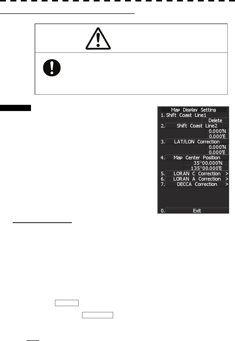
Correcting Chart Position (Map Display Setting)
Procedure 1 Press [RADAR MENU] key.
Press [9] key.
Press [5] key.
Or, hold down the [Map] key.
Sea chart menu (Map Setting) opens.
2 Press [5] key.
The Map Display Setting Menu will appear.
There are three methods for correcting the chart
position.
[1] Shift Coast Line 1
Set the correction value by operating the cursor.
1 Press [1] key while the Map Display Setting Menu is open.
The chart display position correction 1 (Shift Coast Line 1) is set.
2 Move the cursor to the chart on which a position is to be corrected, and
press [ENT] key.
3 Move the cursor to the radar video of which position is to be corrected,
and press [ENT] key.
SETTING (correcting) will be indicated for Shift Coast Line 1.
At this time, MAP SHIFT will appear at software button ⑪ located at the bottom
right corner of the radar display described in Section 2.3.4, indicating that the position is
being corrected.
Note: A correction value can be operated in the range -9.999’ to +9.999’.
When the chart position is corrected, the display will be
shifted away from the actual position. With this in mind,
navigate your ship with attention to the surroundings.
Otherwise, this may cause accidents.
Caution
3.9 APPLIED OPERATIONS
3─132
3
y
y y
Cancellation of Shift Coast Line 1
1 Press [1] key while the MAP Display Setting Menu is open.
DELETE (no correction) will be indicated for Shift Coast Line 1.
At this time, MAP SHIFT will disappear from software button ⑪ located at the
bottom right corner of the radar display described in Section 2.3.4.
[2] Shift Coast Line 2
Set a correction value pressing the numeric values.
A correction value can be entered in the range -9.999’ to +9.999’.
1 Press [2] key while the Map Display Setting Menu is open.
The latitude / longitude input screen for the Shift Coast Line2 menu will appear.
2 Enter the correction value for the latitudinal direction, pressing the
numeric keys.
To switch between the north and south, turn the [MULTI] control.
3 Press [ENT] key.
The correction value for the latitudinal direction will be determined.
4 Enter the correction value for the longitudinal direction, pressing the
numeric keys.
To switch between the east and west, turn the [MULTI] control.
5 Press [ENT] key.
The correction value for the longitudinal direction will be determined.
At this time, MAP SHIFT will appear at software button ⑪ located at the bottom
right corner of the radar display described in Section 2.3.4, indicating that the position is
being corrected.
Cancellation of Shift Coast Line 2
1 Press [2] key while the MAP Display Setting Menu is open.
The chart position correction value input screen will appear.
2 Press [0] key, and then [ENT] key.
The correction value for the latitudinal direction will be set to 0.
3 Press [0] key, and then [ENT] key.
The correction value for the longitudinal direction will be set to 0.
At this time, MAP SHIFT will disappear from software button ⑪ located at the
bottom right corner of the radar display described in Section 2.3.4.

3─133
[3] LAT/LON Correction
This method corrects a chart position by changing the values of latitude and longitude that are sent by the
navigation equipment.
Only our service engineers are to use this correction method because the contents of data such as trails
data to be saved are changed when the method is used.
A correction value can be entered in the range -9.999’ to +9.999’.
1 Press [3] while the MAP Display Setting Menu is open.
The latitude / longitude input screen for the LAT/LON Correction menu will appear.
2 Enter the correction value for the latitudinal direction, pressing the
numeric keys.
To switch between the north and south, turn the [MULTI] control.
3 Press [ENT] key.
The correction value for the latitudinal direction will be determined.
4 Enter the correction value for the longitudinal direction, pressing the
numeric keys.
To switch between the east and west, turn the [MULTI] control.
5 Press [ENT] key.
The correction value for the longitudinal direction will be determined.
Cancellation of LAT/LON Correction
1 Press [3] key while the MAP Display Setting Menu is open.
The latitude/longitude correction value input screen will appear.
2 Press [0] key, and then [ENT] key.
The correction value for the latitudinal direction will be set to 0.
3 Press [0] key, and then [ENT] key.
The correction value for the longitudinal direction will be set to 0.

3.9 APPLIED OPERATIONS
3─134
3
y
y y
[4] MAP Center Position
This method corrects a chart position by entering the values of latitude and longitude at own ship’s
position in manual mode.
If latitude and longitude data sent by the navigation equipment has been entered, the data has priority
over the manually entered values.
1 Press [4] key while the MAP Display Setting Menu is open.
The latitude / longitude input screen for the Map Center Position menu will appear.
2 Enter the value as latitudinal, pressing the numeric keys.
To switch between the north latitude and south latitude, turn the [MULTI] control.
3 Press [ENT] key.
The entered value will be determined as latitude.
4 Enter the value as longitude, pressing the numeric keys.
To switch between the east longitude and west longitude, turn the [MULTI] control.
5 Press [ENT] key.
The entered value will be determined as longitude.
Note: The function is available in the plotter mode only.
3─135
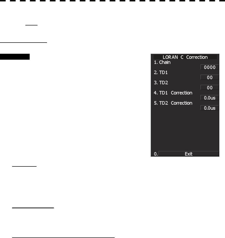
3.9.7 Set LORAN C (LORAN C Correction)
Note: Plotter option (NDB-44) is necessary to enable LORAN C time difference display.
Setting LORAN C
Procedure 1 Press [RADAR MENU] key.
Press [9] key.
Press [5] key.
Press [5] key.
Press [5] key.
The LORAN C Correction Menu will appear.
The chain and time difference for LORAN C
time difference display can be set by changing
the settings of the menu items.
[1] Chain
• Set the chain.
• Enter the value in the range 0000 to 9999 by using the numeric keys.
• Only a value in the table can be entered.
[2] TD1, [3] TD2
• Enter the TD value for slave station 1/2.
[4] TD1 Correction, [5] TD2 Correction
• Enter the sound velocity time correction value for the TD value of slave station 1/2.

3.10 USE FUNCTION SWITCH
3─136
3
y
y y
3.10 USE FUNCTION SWITCH [FUNC]
“Radar Function Setting” is provided for always obtaining the best radar video by storing complex radar signal
processing settings in the optimum status by use, and calling the setting in accordance with the conditions for
using the function.
Functions are factory-set for general use, and the settings can be fine adjusted by operating the menu.
Four function modes are available, and they are factory-set as follows:
Function 1: COAST Useful for observing short-range videos
Function 2: DEEP SEA Suitable for general ocean navigation
Function 3: FISH NET Useful for small target.
Function 4: STORM Useful for observing videos in stormy weather
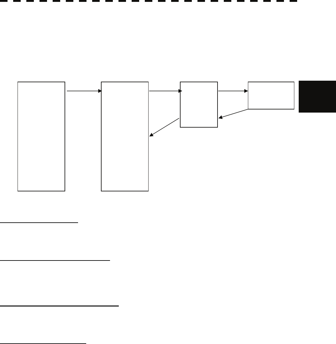
3.10.1 Operation Procedure
Calling a Function
Procedure 1 Press the [FUNC] key.
Each time the [FUNC] key is pressed, the selection changes cyclically as follows:
Function Off → Function 1 → Function 2 → Function 3 → Function 4 → Function Off
The currently called function mode will be indicated at the lower left of the radar display.
* Switching can be done each time software button ⑤ located at the bottom left corner
of the radar display described in Section 2.3.2 is pressed.
Changing Function Setting (temporary change)
• When radar signal processing setting is changed by using the menu or button on the radar
display while function 1 to 4 is called, the change is temporarily reflected to the operating state.
• Since this method does not change the memory contents, the new setting is deleted as soon as
another function is called.
• When the previous function is called again, operation is performed according to the memory
contents.
Changing Function Setting (memory contents change)
• To change the memory contents of functions 1 to 4, use the function setting menu.
• To display the function setting menu, press [RADAR MENU] twice, [6] key, and then [8] key.
• Press the numeric key corresponding to the target function number.
• The function setting menu consists of five pages. To switch between the pages, select [0] key
Previous Page or [9] key Next Page.

3─137
3.10.2 Function Setting Menu Items
The function setting menu has the items below.
Page 1
Page 2
Page 3
Page 4
Page 5
1. Mode Name of the mode to be used
2. IR Radar interference rejection OFF/LOW/MEDIUM/HIGH
3. Process Video process OFF/・・・・
4. Target Enhance Target expansion OFF/ LEVEL1/LEVEL2/LEVEL3
5. Auto STC/FTC Automatic clutter suppression OFF/AUTO SEA/AUTO RAIN
6. Save Present State Saving of the present state
1. Pulse Length 0.75nm Standard pulse length of 0.75 nm range PL1/PL2
2. Pulse Length 1.5nm Standard pulse length of 1.5 nm range PL1/PL2/PL3
3. Pulse Length 3/4nm Standard pulse length of 3 nm range PL1/PL2/PL3
4. Pulse Length 6/8nm Standard pulse length of 6 nm range PL1/PL2/PL3
5. Pulse Length 12nm Standard pulse length of 12 nm range PL1/PL2/PL3
6. Pulse Length 16nm Standard pulse length of 16 nm range PL1/PL2/PL3
8. Pulse Length Pattern Pulse Length Pattern 3NM/6NM/12NM
1. Video Latitude Dynamic range of radar video NORMAL/WIDE/NARROW
/SUPER WIDE
2. Video Noise Rejection Radar video noise rejection OFF/LEVEL1/LEVEL2
3. Auto DR Control Automatic dynamic range control OFF/ON
4. Process Switch Radar video process switching OFF/RANGE FIX/AUTO
5. 2nd Process Mode Second video process mode OFF/・・・・
6. Process Switch Range Video process switching range Range setting
7. Fast Target Detection Fast moving target detection OFF/ON
1. Trails Interval Radar trails length OFF/・・・・
2. Trails Mode Radar trails mode TRUE/RELATIVE
3. Trails REF Level Radar trails plotting threshold LEVEL1-4
4. Trails Reduction Thinning of radar trails OFF/LEVEL1-3
5. Time/Cont Combine Superimpose-display of time radar
trails and continuous radar trails OFF/ON
6. Trails Process Radar trails video process OFF/ON
7. Max Interval Maximum time for radar trails display SHORT/MEDIUM/LONG/SUPER LONG
1. Gain Offset Sensitivity correction Correction value setting
2. PRF Transmitting repetition frequency NORMAL/ECONOMY/HIPOWER
3. Small Buoy Detection Small target detection mode OFF/ON
4. Fishnet Detection Fishnet detection mode OFF/ON
5. Antenna Height Antenna height DEFAULT/-5m/5-10m/10-20m/20m
8. Set Mode Default Initialization Yes/No

3.10 USE FUNCTION SWITCH
3─138
3
y
y y
3.10.3 Overview of Function Operations
The following outlines the operation of each function selected from the function setting menu:
Procedure 1 Press the [FUNC] key for 2 seconds.
The User Function Setting menu will appear.
Specify the number for the function for which the settings are to be changed.
The following are the operation overviews of each function setting item.
[Page 1] [1] MODE (Mode)
• Selects the function name to be indicated at the lower left of the radar display when the function is
selected.
• When the setting is changed back to the factory setting, the initial value of the selected mode is called.
• The following 11 modes are provided:
COAST: Use this mode to monitor a relatively short range, for example, bays and coasts
where many boats and ships are running. (Importance is attached to resolution.)
DEEPSEA: Use this mode to monitor a relatively long range, for example, the open sea.
(Importance is attached to long-range sensitivity.)
FISHNET: Use this mode to detect small targets such as fishnets of round haul netters hidden
by sea clutter returns. (Importance is attached to sea clutter suppression, and
sensitivity to moving targets lowers.)
STORM: Use this mode when many rain/snow clutter returns or sea clutter returns are
detected in stormy weather. (Importance is attached to rain/snow clutter and sea
clutter suppression, and sensitivity slightly lowers.)
CALM: Use this mode when only a few rain/snow clutter returns or sea clutter returns are
detected.
RAIN: Use this mode when sea clutter is not strong but rain/snow clutter is strong.
(Importance is attached to rain/snow clutter suppression, and sensitivity slightly
lowers.)
BIRD: Use this mode to detect tens of seabirds at low altitude during coastal navigation
or hundreds of seabirds at high altitude during ocean navigation.
LONG: Use this mode to detect small targets at relatively long distance in the open sea.
Buoy: Use this mode to detect small targets like radio buoys in areas outside the sea
clutter area. (This mode displays targets of which detection probability is low.)
USER1: General mode used when the nine modes above are not applicable
USER2: General mode used when the nine modes above are not applicable
[Page 1] [2] IR (radar interference rejection)
• Same function as IR in the RADAR Menu
[Page 1] [3] Process (video process)
• Same function as PROCESS in the RADAR Menu
[Page 1] [4] Target Enhance
• Same function as TARGET ENHANCE in the RADAR Menu

3─139
[Page 1] [5] Auto SEA/RAIN (Auto STC/FTC)
• Detects unwanted waves such as rain/snow clutter and sea clutter and automatically suppresses them.
• When the sea state or weather changes, this function automatically performs suppression processing in
accordance with the situation.
• Suppression processing is not full automatic, and requires the operator to control the afterimages of
unwanted waves.
• To control the afterimage of sea clutter, use the [SEA] control.
• To control the afterimage of rain/snow clutter, use the [RAIN] control.
• In areas where the density of unwanted waves is low, unwanted waves may remain being judged as
targets. Thus, use the automatic clutter suppression mode together with the video process mode.
• Characteristics of the automatic clutter suppression function:
OFF: Disables the automatic clutter suppression function.
Select OFF when rain/snow clutter and sea clutter are not strong or when the ship
is in a bay.
AUTO SEA: Automatically detects the strength of sea clutter, and performs the most suitable
sea clutter suppression processing.
Even when the strength of sea clutter varies depending on the wind direction,
AUTO SEA performs the most suitable suppression processing.
Land like islands can be displayed naturally.
Since rain clouds outside sea clutter areas are recognized as land, there is no effect
of suppressing rain/snow clutter.
AUTO RAIN: Along with AUTO SEA, AUTO RAIN automatically detects the strength of
rain/snow clutter, and performs the most suitable rain/snow clutter suppression
processing.
When rain clouds are scattered about, AUTO RAIN performs rain/snow clutter
suppression processing for only the rain-cloud areas.
Since land is recognized as rain clouds, land videos become obscure.
[Page 1] [6] Save Present State (Save Present State)
• Registers the currently used settings as function settings.
[Page 2] [1]-[6] PL (Pulse Width)
• Sets the standard transmitter pulse length in each range.
• When the range is called, the pulse range is used.
[Page 2] [8] Pulse Length Pattern
• Select a combination of pulses as a pulse width that can be used for each range of 3/6/12 NM.
[Page 3] [1]-[7] Radar signal processing settings (Process Setting)
• Same functions as those in the Process Setting Menu generally used
[Page 4] [1]-[7] Radar trails settings (Trails Setting)
• Same functions as in the RADAR Trails Setting of the RADAR Menu generally used

3.10 USE FUNCTION SWITCH
3─140
3
y
y y
[Page 5] [1] Gain Offset
• Corrects sensitivity while the function mode is called.
• Since the displayed noise level varies depending on the combination of the video process mode and the
interference rejection level, sensitivity needs fine adjustment for always obtaining the highest level.
• The sensitivity correction function saves the correction value set by the sensitivity control in each
function mode, so it can obtain the highest sensitivity without the sensitivity control being operated
when the function mode is changed.
• To set high sensitivity, set a value on the “+” side.
• To set low sensitivity, set a value on the “-” side.
• When the radar interference rejection level is increased, the noise level is lowered. Thus, set a
sensitivity correction value to the “+” side.
• When the video process mode 3SCAN CORR, 4SCAN CORR, or 5SCAN CORR is used, the noise
level is lowered. Thus, set a sensitivity correction value to the “+” side.
• When the video process mode REMAIN or PEAK HOLD is used, noise is hard to disappear. Thus,
set a sensitivity correction value to the “-” side.
[Page 5] [2] PRF
• Same function as in the TXRX Setting of the Main Menu generally used
[Page 5] [3] Small Buoy Detection
• Reduces the loss of signal processing during detection of small targets.
OFF: Activates the general signal processing mode.
ON: Activates the small buoy detection mode that reduces the loss of signal processing.
[Page 5] [4] Fishnet Detection
• Use this mode to detect small targets hidden by sea clutter returns.
• This function becomes more effective when the AUTO RAIN clutter suppression function is used
together.
OFF: Activates the general signal processing mode.
ON: Activates the fishnet detection mode.
[Page 5] [5] Antenna Height
• Set the height of radar antenna above sea level.
• The STC/FTC curve is changed.
-5m : Set the antenna height under 5m.
5-10m : Set the antenna height 5m to 10m.
10-20m : Set the antenna height 10m to 20m.
20m- : Set the antenna height over 20m.

3─141
[Page 5] [8] Set Mode Default
• Sets the initial value of a selected function setting mode.
Select this item to change the current function mode to the initial value.
[Page 5] [9] Initialize
• Sets the function settings to the factory-set values.
Select this item to change all the function settings to the factory-set values.
3.10 USE FUNCTION SWITCH
3─142
3
y
y y
3.10.4 Overview of Stored Function Setting Data
The overview of stored function setting data is as follows:
• Factory-set data: Stored data that general operation cannot change
• Default data: Standard data of each function mode that users can change
• Data that can be called: Stored data that can be called by pressing the [FUNC] key
[Page 1] [1] Call Mode
• Calls the standard setting of the mode, and stores it for the function number.
[Page 1] [6] Save Present State
• The currently operating state can be stored for the function number.
• Use this function to store the state of good setting that will be frequently used.
[Page 5] [8] Save Default of Mode
• Stores the setting of the current function number, as the default setting of the mode.
[Page 5] [9] Initialization
• Changes the memory contents of the mode, which is used with the current function number, back to the
factory setting.
COAST
DEEPSEA
FISHNET
STORM
CALM
RAIN
BIRD
LONG
Buoy
USER1
USER2
COAST
DEEPSEA
FISHNET
STORM
CALM
RAIN
BIRD
LONG
Buoy
USER1
USER2
FUNC1
FUNC2
FUNC3
FUNC4
PRESENT
[5]-[8] [1]-[1]
[5]-[7]
[FUNC]
[1]-[7]
Function Setting
Factory-set data
Function Setting
Default data
Function Setting
Data that can be called Current data
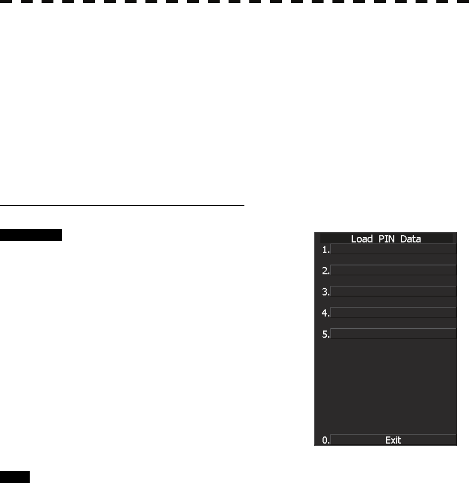
3─143
3.10.5 Personal Information (PIN Setting)
The operation status of the radar is recorded. If the system is operated by more than one operator, the
operators can register operation status as suitable for them and call the status. Operation status for up to
five operations can be registered, and a name can be assigned to each status. (Up to 10 alphanumeric
characters)
* Data stored as personal information
• Day/Night mode setting
• Brilliance
• Alarm volume
• Vector length/mode
• Various types of image processing (IR, ENH, PROC, FUNC)
[I] Calling Operation Status (Load PIN Data)
Procedure 1 Press [RADAR MENU] key twice.
Press [8] key.
The Radar Sub Menu will appear.
2 Press [1] key.
The PIN Setting Menu will appear.
3 Press [1] key.
The Load PIN Data Menu will appear.
4 Select the item you want to load,
pressing the numeric keys [1] to [5].
The Load Execution Check Menu will appear.
Select “Yes” for loading.
Exit 1 Press [RADAR MENU] key.
The Target Information Display Menu will reappear.
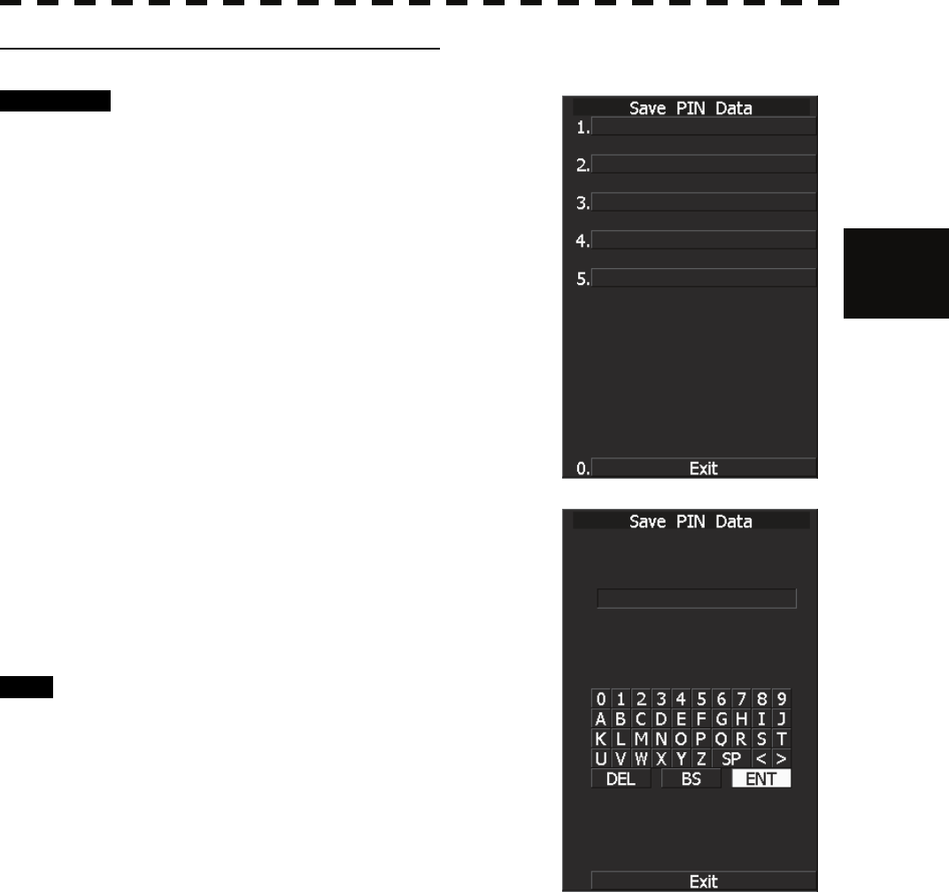
3.10 USE FUNCTION SWITCH
3─144
3
y
y y
[II] Saving Operation Status (Save PIN Data)
Procedure 1 Press [RADAR MENU] key twice.
Press [8] key.
The Radar Sub Menu will appear.
2 Press [1] key.
The PIN Setting Menu will appear.
3 Press [2] key.
The Save PIN Data Menu will appear.
4 Select the number corresponding to
the place where you want to save
status, pressing the numeric keys [1] to
[5].
The Code Input Menu will appear.
5 Using numeric key, enter the name and
then move the cursor onto the “ENT”
button and press [ENT] key.
Data will be saved with the entered name.
Exit 1 Press [RADAR MENU] key.
The Target Information Display Menu will
reappear.
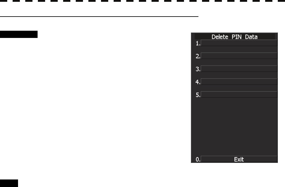
3─145
[III] Erasing Registered Operation Status (Delete PIN Data)
Procedure 1 Press [RADAR MENU] key twice.
Press [8] key.
The Radar Sub Menu will appear.
2 Press [1] key.
The PIN Setting Menu will appear.
3 Press [3] key.
The Delete PIN Data Menu will appear.
4 Select the file you want to erase,
pressing the numeric keys [1] to [5].
The Delete Execution Check Menu will appear.
Select “Yes” for deletion.
Exit 1 Press [RADAR MENU] key.
The Target Information Display Menu will reappear.
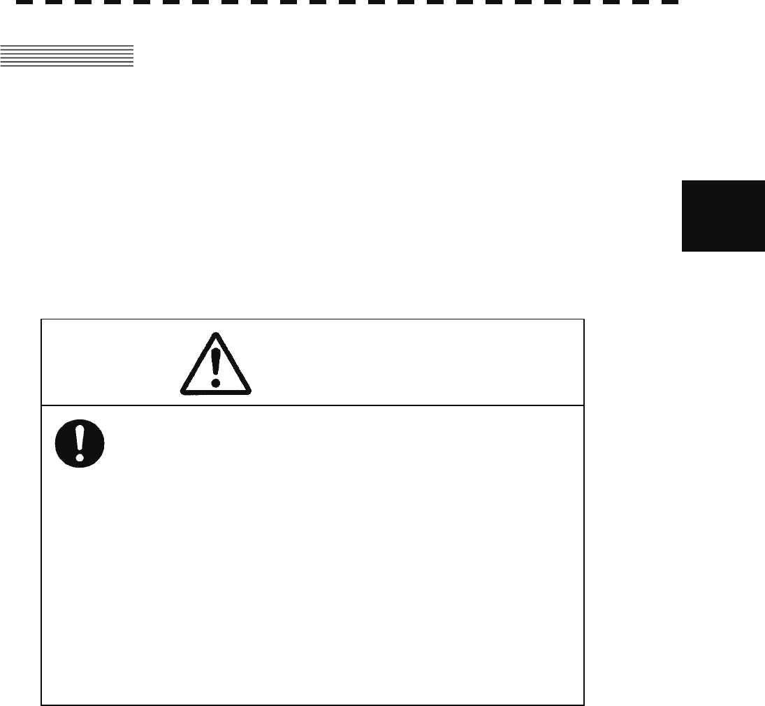
3.11 USING CARD
3─146
3
y
y y
3.11 USING CARD
This radar has two card slots. Inserting a flash memory card (option) into a card slot, you can save the
following contents, saved in the processor, in the card or can read data from the card to the processor.
• Trails of own ship: 7000 points maximum
• Track of other ship: 20 target×1500 points (TT or AIS option)
• Mark Line: 20000 points maximum (plotter option)
• Waypoint: 99 points maximum (plotter option)
• Route: 10 routes maximum (plotter option)
These pieces of information can be saved in a flash memory card as a file. The internal capacity is as
large as only a file. An internally created file can be saved until the flash memory card is full.
◎ Recommendations on using CF cards.
★ Recommended card size.
64 MB, 128 MB, 256 MB, 512 MB, 1GB.
★ Recommended file system.
The Compact card should be formatted to FAT32 in Windows XP (SP2).
Many CF cards are formatted to FAT16 before shipping. Be sure to Format the CF card
to FAT32, before use.
★ Recommended OS.
Windows XP (SP2).
★ Operating temperature range
Depending on the CF card specification and the radar specification, -15 to +55
degree Celsius.
Caution
Compact Flash Cards can be used with this
system. The following shows
the recommendations in use. However they do
not guarantee that CF cards may properly work
with this system. Depending on the hardware or
software, the cards will not work correctly.
Any damage including loss of data caused
by using the data created on this system is out
of warranty.
Important files should be backed up therefore.
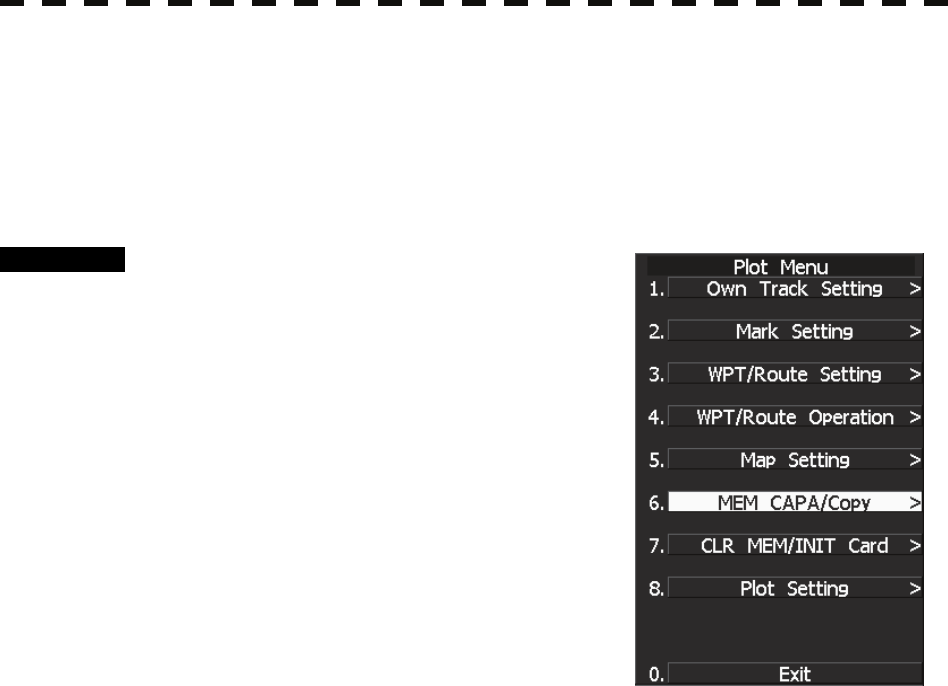
3─147
◎ Caution in use.
Never eject the CF card while files are being written to the card.
Turn the power off before inserting or ejecting a CF card.
3.11.1 Save in and Transfer to Card (MEM CAPA/Copy)
Procedure 1 Press [RADAR MENU] key.
The Radar Menu will appear.
2 Press [9] key.
The Plot Menu will appear.
* Software button ④ located at the operation/message area in
Section 2.3.9 is also available to save and transfer data.
3 Press [6] key.
The MEM CAPA/Copy window will appear.
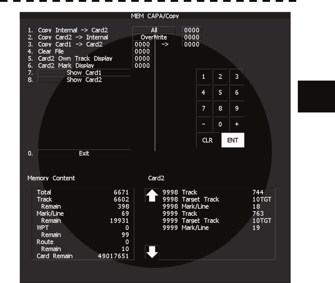
3.11 USING CARD
3─148
3
y
y y
• Information saved in the processor is displayed in the Memory Content.
Total: Total number of data points
Track: Number of data points for own ship's track (7000 points maximum)
Remain: Number of remaining data points of own ship's track that can be saved
Mark/Line: Number of mark and line points made with user map (20000 points maximum only
when a plotter option is installed)
Remain: Number of remaining data points of marks and lines that can be saved
WPT: Number of data points of created waypoints (99 points maximum)
Remain: Remaining waypoints that can be saved
Route: Number of data points of created routes (10 routes maximum)
Remain: Remaining routes that can be saved
• File names and information saved in the card is displayed in Card 2.
• Arrows next to Card 2 are used to scroll the contents of Card 2.
Range +/- keys can be used to scroll also.
• Numeric key is used to give a file name.
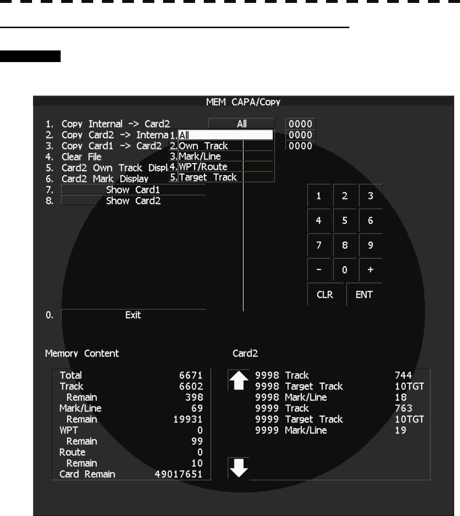
3─149
[I] Copy Internal Information to Card 2 (Copy Internal → Card 2)
Procedure 1 Press [1] key while the CAPA/Copy Menu is open.
The items to be saved are displayed.
2 Select the item to be saved, using the numeric keypad on the keyboard.
A file name to copy Internal information to Card 2 can be entered.
3 Using the numeric key, enter a file name.
After the input, move the cursor onto the “ENT” button in the Code Input menu, and press
[ENT] key.
The system writes internal information into Card 2 with an entered number used as a file
name.
The capacity of information that can be saved in the internal portion is limited to the maximum
number of points in items described on the previous page. For the capacity of information that
can be saved in a card, the system can save information in a card until the card capacity is filled
with a file, counting the information saved in the internal portion as a file.
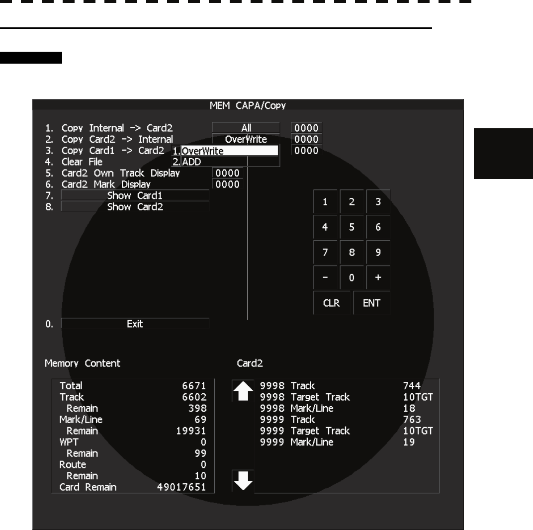
3.11 USING CARD
3─150
3
y
y y
[II] Read Information from Card 2 to Internal Portion(Copy Card 2 → Internal)
Procedure 1 Press [2] key while the CAPA/Copy Menu is open.
2 Using the numeric key, select ADD mode or OVER WRITE mode.
A file name to copy information from Internal portion to Card 2 can be entered.
Read the file name displayed in the Card 2 window.
3 Using the numeric key, enter a file name.
Move the cursor onto the “ENT” button in the Code Input menu, and press [ENT] key.
The entered file name is read from Card 2 to the internal portion.
When information is to be transferred from Card 2 to the internal portion in the ADD mode, the
information can be copied from multiple files. However, information cannot be read when the number
of points for an item has reached the maximum. In the ADD mode, the WPT and Route are overwritten.

3─151
[III] Copy Information from Card 1 to Card 2 (Copy Card 1 → Card 2)
Procedure 1 Press [3] key while the CAPA/Copy Menu is open.
A file name to copy information from Card 1 to Card 2 can be entered.
2 Using the numeric key, enter a file name.
Using the numeric key, euter a file name to be copied.
After having enter the name, move the cursor onto the “ENT” button in the Code Input
menu, and press [ENT] key.
3 Using the numeric key, enter a file name to copy.
After having enter the name, move the cursor onto the “ENT” button in the Code Input
menu, and press [ENT] key. CLR will be cancelled.
The entered file number is copied from Card 1 to Card 2.
[IV] Delete File from Card 2 (Clear File)
Procedure 1 Press [4] key while the CAPA/Copy Menu is open.
A file name to clear file can be entered.
2 Using the numeric key, enter a file name.
After having enter the name, move the cursor onto the “ENT” button in the Code Input
menu, and press [ENT] key. CLR will be cancelled.
The entered file number is deleted from Card 2.
[VI, VII] View Information in Card (Show Card)
Procedure 1 Press [7] or [8] key while the CAPA/Copy Menu is open.
7: Card slot 1
8: Card slot 2
Select a card to be displayed.
Exit 1 Press [0] key.
The MEM CAPA/Copy window will be closed.
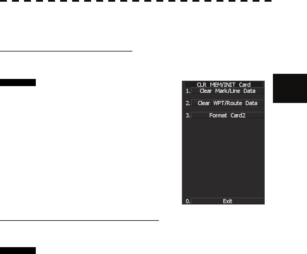
3.11 USING CARD
3─152
3
y
y y
3.11.2 Erase/Initialize Card Memory (CLR MEM/INIT Card)
Erase saved information from inside the processor.
[I] Erase Mark/Line (CLR Mark/Line Data)
Erase saved mark/line from inside the processor.
Procedure 1 Press [RADAR MENU] key.
The Main Menu will appear.
2 Press [9] key.
The Plot Menu will appear.
3 Press [7] key.
The CLR MEM/INT Menu will appear.
4 Press [1] key.
A window will appear to select whether or not
marks/lines should be erased.
1. Erased
2: Cancel
[II] Erase Waypoint/Route (CLR WPT/Route Data)
Erase saved WPT/Route from inside the processor.
Procedure 1 Press [RADAR MENU] key.
The Main Menu will appear.
2 Press [9] key.
The Main Menu will appear.
3 Press [7] key.
The CLR MEM INIT Card Menu will appear.
4 Press [2] key.
The Waypoint/Route Erase Execution window will appear.
1. Erase
2: Cancel

3─153
[III] Initialize Card 2 (Format Card 2)
Initialize Card 2.
Procedure 1 Press [RADAR MENU] key.
The Main Menu will appear.
2 Press [9] key.
The Plot Menu will appear.
3 Press [7] key.
The CLR MEM INIT Card Menu will appear.
4 Press [3] key.
The window to select whether or not Card 2 is initialized will appear.
1. Initialize
2: Cancel

SECTION 4
MEASUREMENT OF
RANGE AND BEARING
4.1 MEASUREMENT USING THE CURSOR WITH THE TRACKBALL . 4-1
4.2 MEASUREMENT BY RANGE RINGS ................................................ 4-2
4.3 MEASUREMENT BY EBLS AND VRMS............................................ 4-3
4.4 MEASUREMENT BETWEEN TWO OPTIONAL POINTS.................. 4-4
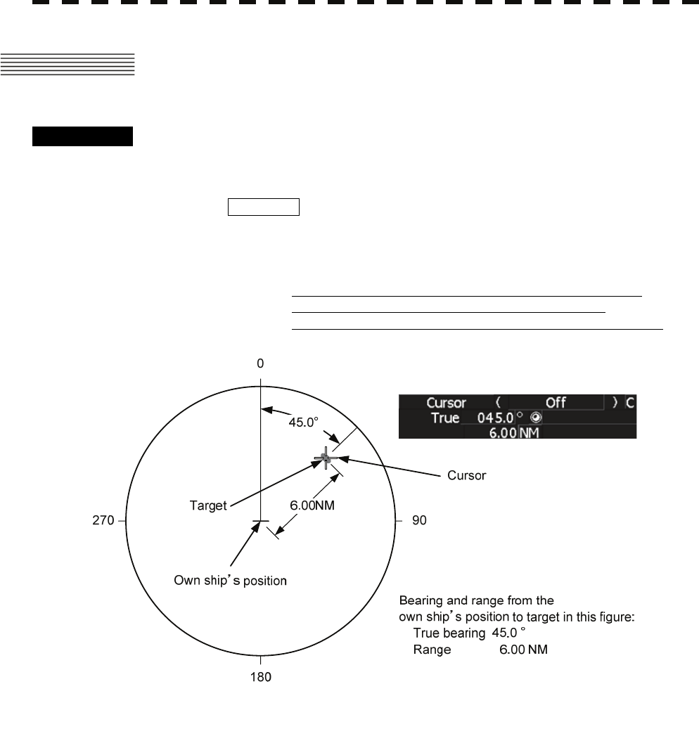
4─1
4.1 MEASUREMENT USING THE CURSOR
WITH THE TRACKBALL
Procedure 1 Check the target echoes on the radar display.
2 Move the cursor mark to a target by the trackball.
The CURSOR on the radar display indicates the bearing and range of the target.
The range is a distance from own ship’s position.
CURSOR ( )
TRUE 45.0°: True bearing of the cursor relative to own ship
5.0nm: Range between the cursor and own ship
REL 45.0°: Relative bearing of the cursor relative to own ship
Figure 4.1

4.2 MEASUREMENT BY RANGE RINGS
4─2
4
y
yyy
4.2 MEASUREMENT BY RANGE RINGS
Procedure 1 Press [RR/HL] key.
Display and non-display of the scale of the range rings is switched every time the
[RR/HL] key is pressed. Also, the scale unit is shown on the Range rings display On /
Off button (Software button ② located at the top left corner of the radar display
described in Section 2.3.1).
Assess the distance to the target based on the location of the target on the range ring
scale.
To change brilliance of the range rings scale, refer to Section 3.3.5 “Adjust Brilliance of
Information on Radar Display (Brilliance Setting).”
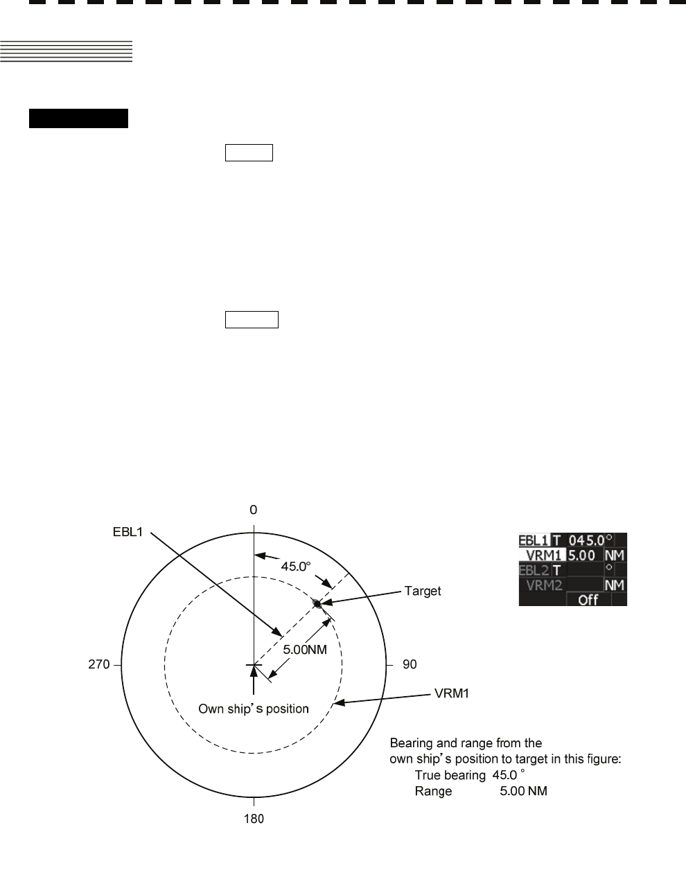
4─3
4.3 MEASUREMENT BY EBLS AND VRMS
Procedure 1 Press [EBL1] key to select EBL1 display and operation.
The EBL1 indication at the upper right of the radar display will be selected and the
EBL1 will appear as a broken-line on the PPI display.
2 Turn the [EBL] control to put EBL1 on a target.
The bearing of the EBL1 will appear at the upper right of the radar display. The EBL1
bearing represents the target’s bearing.
3 Press [VRM1] key to select VRM1 display and operation.
The VRM1 indication at the upper right of the radar display will be selected and the
VRM1 will appear as a broken-line circle on the PPI display.
4 Move the broken-line VRM1 to the target by using the [VRM]
control.
The range of the VRM1 from own ship will appear at the upper right of the radar
display. The range of VRM1 signifies a distance between the target and own ship.
Refer to Figure 4.2.
Figure 4.2
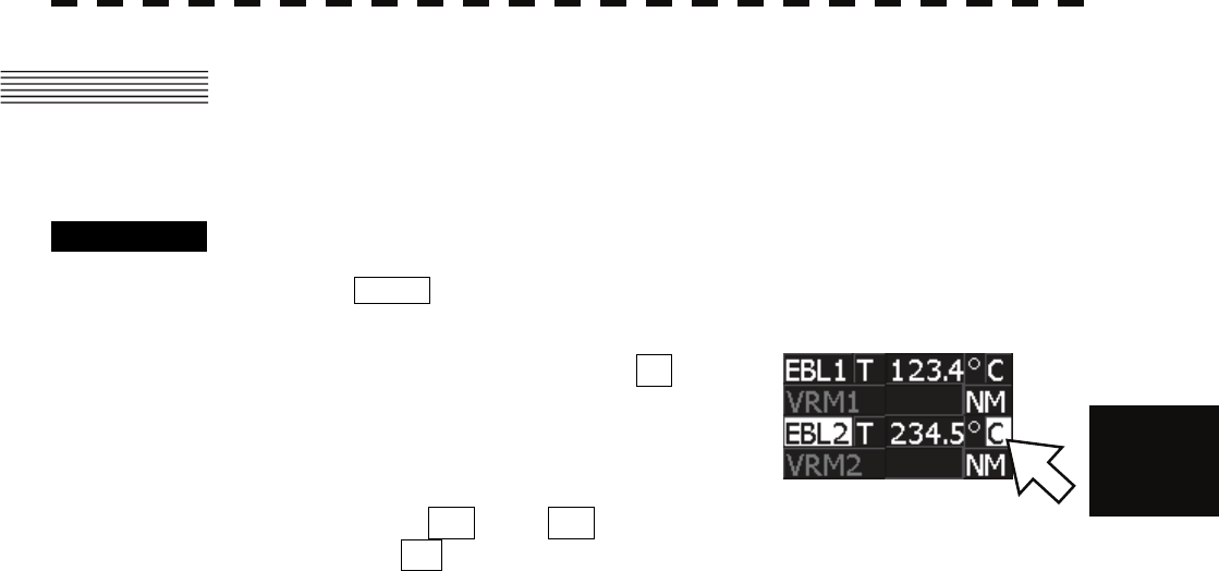
4.4 MEASUREMENT BETWEEN TWO OPTIONAL POINTS
4─4
4
y
yyy
4.4 MEASUREMENT BETWEEN TWO
OPTIONAL POINTS
Procedure 1 Press [EBL2] key to select EBL2 display and operation.
The EBL2 indication at the upper right of the radar display will be selected and the
EBL2 will appear as a dotted-line on the PPI display.
2 Place the cursor over the .
button of EBL2 at the top right
corner of the radar screen, and
press the [ENT] key.
The EBL cursor mode changes
between C and D every time the button is pressed.
Select C .
3 Using the trackball, move the starting point of EBL2 to one (A)
of the two points and press [ENT] key.
(See Figure 4.3.)
4 Turn the [EBL] control to move EBL2 to the other point (B).
(See Figure 4.3.)
5 Press [VRM2] key to select VRM2 display and operation.
{ (VRM marker) will appear on a dotted-line of the EBL2.
6 Using the [VRM] control, move the VRM2 marker on a
dotted-line of EBL2 to the point B.
The bearing and range between the two points will appear in the VRM2 and EBL2 area
on the lower right of the radar display.
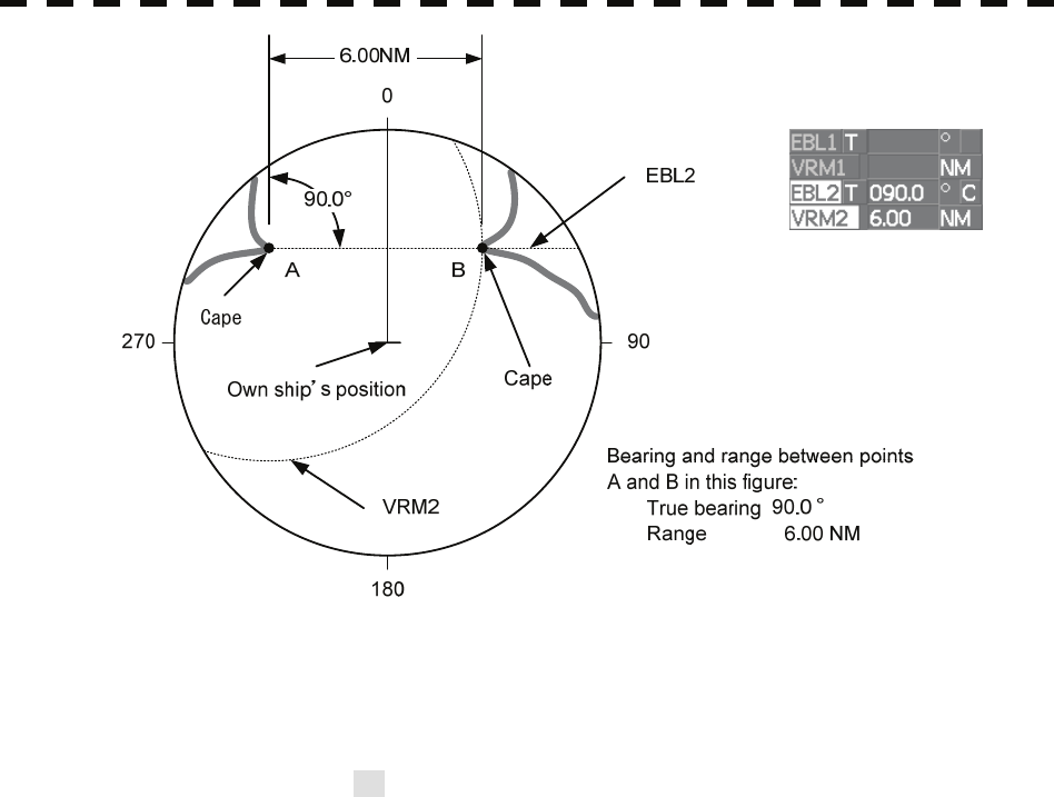
4─5
Figure 4.3
It is also possible to use EBL1 instead of EBL2 in measuring the bearing and range
between two optional points.
In this case, read EBL2 as EBL1 and VRM2 as VRM1 in the procedure above, point the
cursor to C of EBL2 in step 2, and then press [ENT] key.
SECTION 5
OPERATION OF TT AND AIS
5.1 PREPARATION ............................................................ 5-2
5.1.1 Collision Avoidance ............................................. 5-3
5.1.2 Definitions of Symbols ........................................ 5-6
5.1.3 TT Data Display....................................................5-11
5.1.4 Cursor Modes (Cursor) ...................................... 5-13
5.1.5 Setting Collision Decision Criteria
(CPA/TCPA Limit) ................................................ 5-14
5.1.6 Setting CPA Ring (CPA Ring) ............................ 5-15
5.1.7 Setting Vectors (Vector Time)............................ 5-16
5.1.8 Setting the GPS antenna location..................... 5-17
5.2 TT OPERATION ......................................................... 5-18
5.2.1 Acquiring Target [ACQ]...................................... 5-19
5.2.2 Canceling Unwanted Targets ............................ 5-22
5.2.3 Tracking Target Data Display [TGT DATA] ....... 5-23
5.2.4 Displaying Target ID No.
(Target Number Display) .................................... 5-25
5.2.5 Input of target information
(TT Individual Setting)........................................ 5-26
5.2.6 Reference Target (Reference) ........................... 5-29
5.2.7 TT Test Menu....................................................... 5-31
5.3 AIS OPERATION........................................................ 5-37
5.3.1 Restrictions......................................................... 5-37
5.3.2 Initial Setting ....................................................... 5-38
5.3.3 Setting AIS Display Function (AIS Function)... 5-40
5.3.4 Activating AIS Targets (Activate AIS) ............... 5-41
5.3.5 Deactivating AIS Targets (Deactivate AIS)........5-42
5.3.6 Displaying Numeric Data of AIS Targets
(TGT DATA) .......................................................... 5-43
5.3.7 Displaying Target ID No.
(Target Number Display)..................................... 5-48
5.3.8 Setting AIS Filter (AIS Filter Setting)................. 5-49
5.3.9 Conditions for Deciding AIS Target
to be Lost ............................................................. 5-53
5.3.10 Setting AIS Alarm (AIS Alarm Setting) ............ 5-54
5.4 TARGET ASSOCIATION ASSESSMENT
(ASSOCIATION SETTING)......................................... 5-55
5.4.1 Target Association Assessment........................5-55
5.4.2 Priority .................................................................5-56
5.4.3 Azimuth................................................................5-56
5.4.4 Distance ............................................................... 5-57
5.4.5 Course.................................................................. 5-57
5.4.6 Speed ...................................................................5-58
5.4.7 Hysteresis............................................................ 5-59
5.4.8 Non-Hysteresis.................................................... 5-60
5.4.9 AIS Target to be Assessed ................................. 5-61
5.5 ALARM DISPLAY ....................................................... 5-62
5.6 TRACK DISPLAY........................................................ 5-68
5.6.1 Display Past Tracks (Past Position)..................5-68
5.6.2 Other Ship's Tracks (Target Track Setting) ......5-69

5─1
USAGE OF TARGET TRACKING FUNCTION
z There are the following limitations on use of the target
acquisition and target tracking functions.
[I] Resolution between adjacent targets and swapping during
automatic target tracking
Depending on the particular distance and echo size, resolution between
adjacent targets during automatic target tracking usually ranges
somewhere between 0.03 to 0.05 NM. If multiple targets approach each
other, resolution will become about 0.05 NM and this may cause the
system to regard them as one target and thus to swap them or lose part
of them. Such swapping or less of targets may also occur if the picture
of the target being tracked is affected by rain/snow clutter returns or sea
clutter returns or moves very close to land.
[II] Intensity of echoes and the target tracking function
The intensity of echoes and the tracking function have a correlationship,
and thus the target will be lost if no echoes are detected during six
scans in succession. If a lost target exists, therefore, radar gain must be
increased to support detection of the target. If, however, radar gain is
increased too significantly, sea clutter returns or other noise may be
erroneously detected and tracked as a target, and resultingly, a false
alarm may be issued.
[III] Adverse effects of error sources on automatic tracking
To execute accurate tracking, it becomes necessary first to appropriately
adjust the [GAIN], [SEA] and [RAIN] dials of the radar so that the target
to be acquired and tracked id clearly displayed on the radar display.
Inappropriate settings of these adjustments reduce the reliability /
accuracy of automatic tracking.
Attention

5.1 PREPARATION
5─2
5
yy
yyy
5.1 PREPARATION
This section explains the features of the target tracking and AIS functions, and the initial setting for using each
function.
Before the target tracking function or AIS function can be used, the corresponding optional device must be
installed.
Target Tracking Function
The target tracking function calculates the course and speed of a target by automatically tracking the
target's move.
The target tracking function enables the automatic acquisition of targets by using the automatic
acquisition zone function.
If the mode is ground stabilization, SOG/COG used for own ship's information in target tracking. If the
mode is sea stabilization, SPD (speed through the water) / HDG (heading) used for own ship's
information in target tracking.
The target tracking function is available when a target tracking unit (option) is installed.
AIS (Automatic Identification System) function
The AIS function shows the target’s information on the radar display, using other ship's information sent
out from the AIS unit.
This function is available when the optional AIS unit is installed.
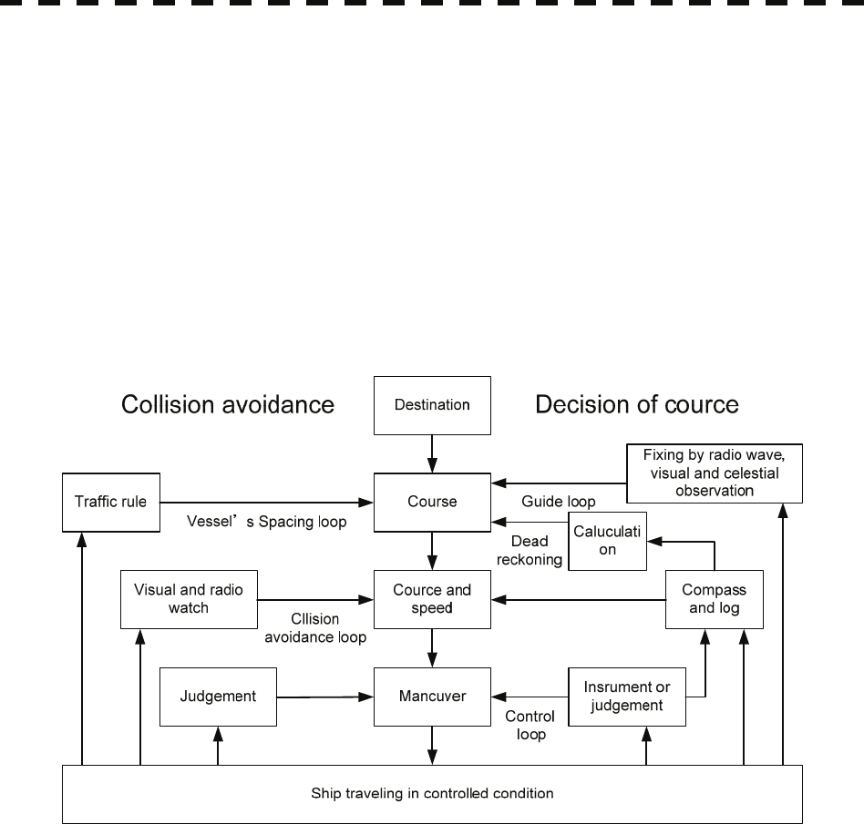
5─3
5.1.1 Collision Avoidance
Problems of Collision Avoidance in Navigation
Marine collision avoidance is one of the problems that have been recognized from of old. Now, it will be
described briefly who the collision avoidance is positioned among the navigational aid problems.
The navigation pattern of all mobile craft constitutes a system with some closed loops regardless of the media
through which the mobile craft travels, whether air, water, the boundary between air and water, or space. This
pattern consists of two closed loops in principle, one of which is a collision with another mobile craft and the
other is a loop of finding a right and safe way to reach a predeterminate destination. Fig. 5-1 shows the
conceptual diagram of navigation pattern by MR. E.W. Anderson. The closed loop of collision avoidance is
shown on the left side and the closed loop of finding a right course on the right side.
Fig. 5-1 Navigation Pattern
Marine Accidents and Collisions
Among marine accidents, collision accidents have been highlighted as the tonnages and speeds of ships become
higher along with the increase in traffic at sea. If a tanker carrying dangerous articles such as crude oil collides
with any other vessel, then not only the vessels involved with the accident but other vessels in the vicinity, port
facilities, inhabitants in the coastal area as well as marine resources may also suffer immeasurable damages and
troubles. Collision accidents have a high percentage of the marine accidents that have occurred in recent years.
To cope with these problems, any effective measures are needed and some equipment to achieve collision
avoidance requirements have been developed at rapid strides.
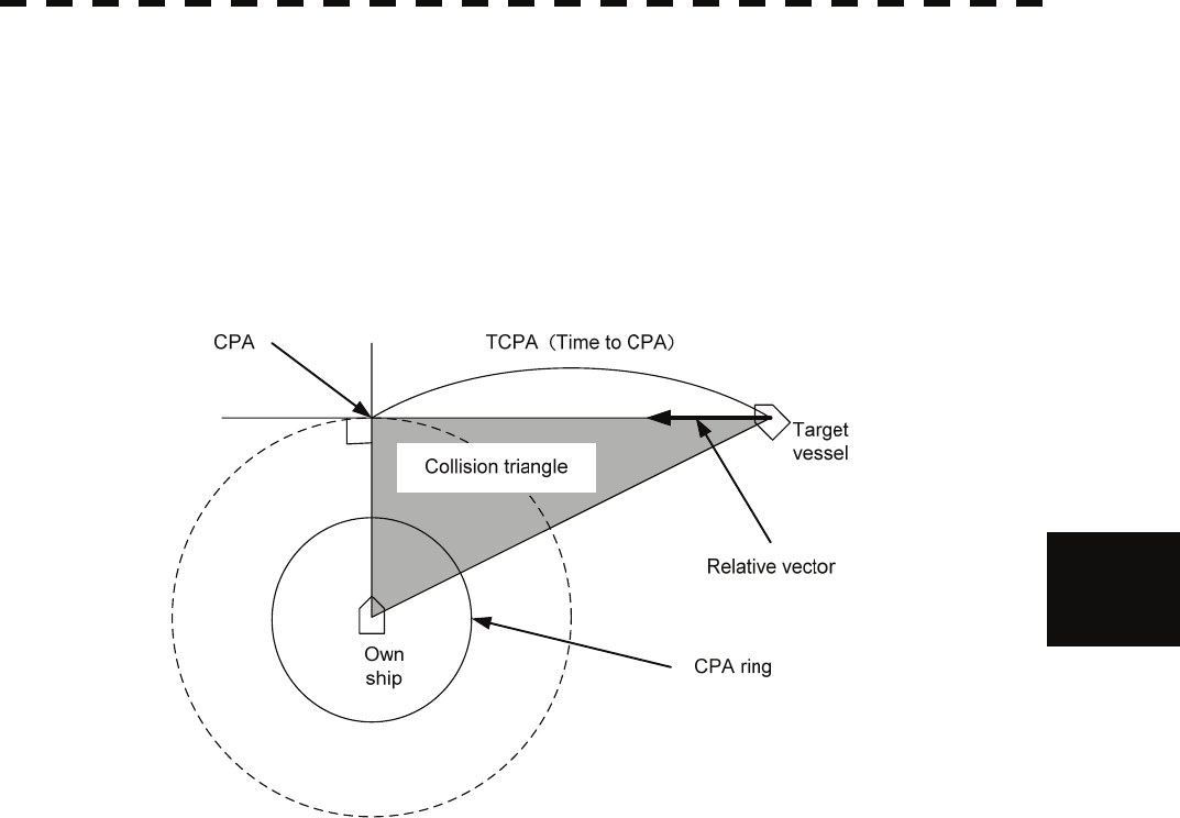
5.1 PREPARATION
5─4
5
yy
yyy
Basic Concept of Collision Avoidance
There are two aspects in collision avoidance: collision prediction and avoidance. Collision prediction is to
predict that two or more vessels will happen to occupy the same point at the same time, while collision
avoidance is to maneuver vessels not to occupy the same point at the same time.
In practical operation of vessels, a spot of collision has to be deemed to be a single point but a closed zone. This
closed zone is conceptually defined as a CPA (Closest Point of Approach). In collision prediction, the time to be
taken until a ship reaches the CPA is defined as a TCPA (Time to CPA).
Fig. 5-2 shows a diagram caked “Collision Triangle”.
Fig. 5-2 Collision Triangle
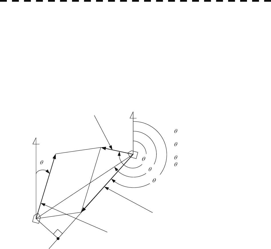
5─5
Relative Vector and True Vector
From two points of view, collision prediction and avoidance, it is necessary to obtain the relative vector of other
ship for prediction and the true vector of other ship for collision avoidance in order to grasp other ship’s aspect.
The relationship between the relative vector and true vector is shown in Fig. 5-3.
Both rough CPA and TCPA can be obtained easily from the relative speed vector of other ship. This method has
an advantage that the risks of collision with all other ships within the radar range can be seen at a glance. On
the other hand, the course and speed of other ship can easily be obtained from its true speed vector, enabling
other ship’s aspect to be seen at a glance. Thus, the aspects of other ships (transverse, outsail, parallel run,
reverse run, etc. ) as described in the act of prevention of collision at sea can be readily grasped. If there is a
risk of collision with other ship, the operator can determine which rule to be applied and how to operate own
ship.
N
T
R
A
O
Vo
VR
VT
VO: Own ship's speed
O: Own ship's course
VT: Other ship's true speed
T: Target ship's true course
VR: Target ship's relative speed
R: Target ship's relative course
A: Aspect
Relative vector
Target ship true vector
N
CPA
Own ship true vector
Fig. 5-3 Relative Vector and True vector
Radar and Collision Avoidance
Radar is still playing an important roll for collision prevention and positioning. A plotter is used to further
enhance the radar functionality. The plotter is capable of plotting other positions of other ships in 3 to 6 minute
intervals to monitor their movement. The plots of other ships represent their tracks relative to own ship, and it is
shown whether there is a risk of collision, namely CPA and TCPA can be obtained. This method using a plotter
is fairly effective, but the number of target ship, which is manually plotted, is limited and it takes several
minutes to measure those.
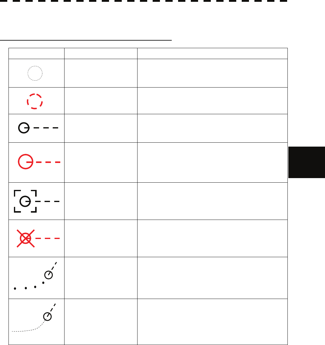
5.1 PREPARATION
5─6
5
yy
yyy
5.1.2 Definitions of Symbols
Types and Definitions of Target Tracking Symbols
Vector/Symbol Definition Remarks
Initial acquisition target This symbol is displayed until the vector is displayed after
target acquisition.
Target acquired in
automatic acquisition zone
The alarm sounds.
The alarm message (New Target) turns red and blinks.
The symbol is red colored.
Tracked target
Dangerous target
The alarm sounds.
The alarm message (CPA/TCPA) turns red and blinks.
The symbol is turns red, and indicates with X mark.
Numeric displayed target When the numeric data is displayed, the target symbol is
enclosed in a square.
Lost target
The alarm sounds.
The alarm message (Lost) turns red and blinks.
The symbol is turns red, and indicates with X mark.
Past position The past positions of an AIS target are displayed as well as
the target tracking symbol.
Target track The track of another ship as an AIS target is displayed as
well as the target tracking symbol.
12
12
12
12
12
12
12
12
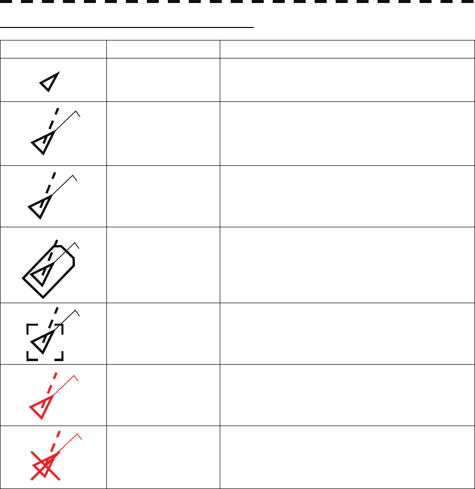
5─7
Types and Definitions of AIS Target Symbols
Vector/Symbol Definition Remarks
Sleeping target
This symbol is displayed when received data is valid.
The direction of the triangle’s vertex indicates the target’s
bow or course.
Activated target
The heading direction is displayed with a solid line, and the
course vector is displayed with a dotted line. The line
perpendicular to the heading direction indicates the direction
to which the course is to be changed. This line may not be
displayed.
Target acquired in
automatic acquisition
zone
The alarm sounds.
The alarm message (New Target) turns red and blinks.
Outline display The outlines of ships are displayed scaled down.
Numeric displayed target When the numeric data is displayed, the target symbol is
enclosed in a square.
Dangerous target
The alarm sounds.
The alarm message (CPA/TCPA) turns red and blinks.
The symbol is turns red, and indicates with X mark.
Lost target
The alarm sounds.
The alarm message (Lost) turns red and blinks.
The symbol is turns red, and indicates with X mark.
Up to a total of 130 activated and sleeping AIS targets can be displayed.
Of which, up to 30 activated AIS targets can be displayed.
If there are more than 130 AIS targets, priority of displaying these targets is as follows:
1. Numeric displayed targets
2. Targets with CPA / TCPA smaller than the set value
(They are considered as dangerous targets and the alarm sounds.)
3. Targets within the automatic activation area
4. Activated AIS targets
5. Targets within the AIS filter (sleeping AIS targets)
If the number of targets exceeds the maximum number of targets that can be displayed within one priority, these
targets are then displayed in accordance with the priority list below:
1. Association targets
2. Activated AIS targets
3. Sleeping AIS targets
AIS12
AIS12
AIS12
AIS12
AIS12
AIS12
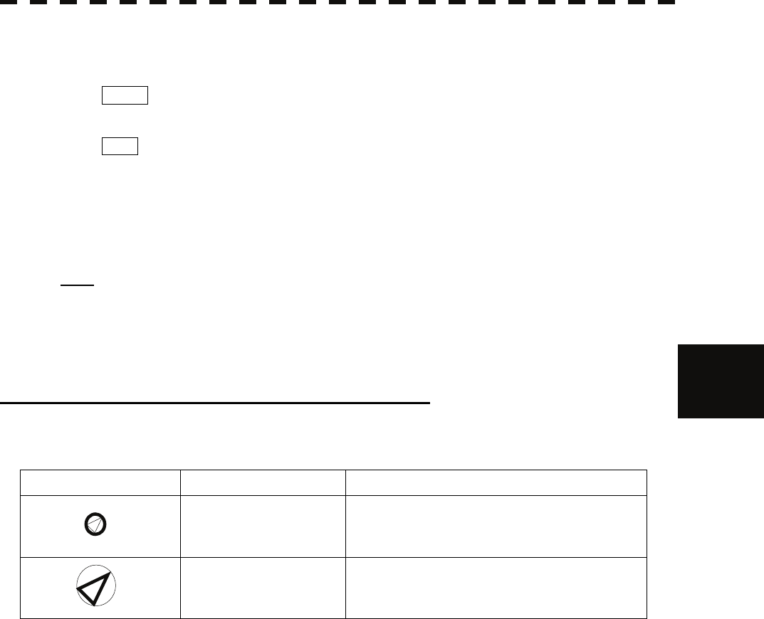
5.1 PREPARATION
5─8
5
yy
yyy
The vector of an AIS target is to be displayed with a vector over ground or over water, depending on the speed
sensor setting and current offset setting. The type of the currently displayed vector can be confirmed by viewing
the setting of the stable mode.
When GND is displayed for the stability mode (⑩ located at the top left corner of the radar display
described in Section 2.3.1):
Vector over ground
When Sea is displayed for the stability mode (⑩ located at the top left corner of the radar display
described in Section 2.3.1):
Vector over water
When the vector of an AIS target is displayed with a vector over water, the system has converted the AIS
target's vector over ground to the vector over water according to the data received from the AIS and the own
ship's information.
Note: When the AIS target's symbol is activated but the vector is not displayed, the following are
probable causes of the trouble:
COG/SOG is not yet input from the GPS.
The selected speed sensor is malfunctioning.
Types and Definitions of Association Target Symbols
When a tracked target and an AIS target are decided as identical, it is displayed with either of the following
symbols:
Vector/Symbol Definition Remarks
Priority for tracked target
Association target
Priority for AIS target
Association target
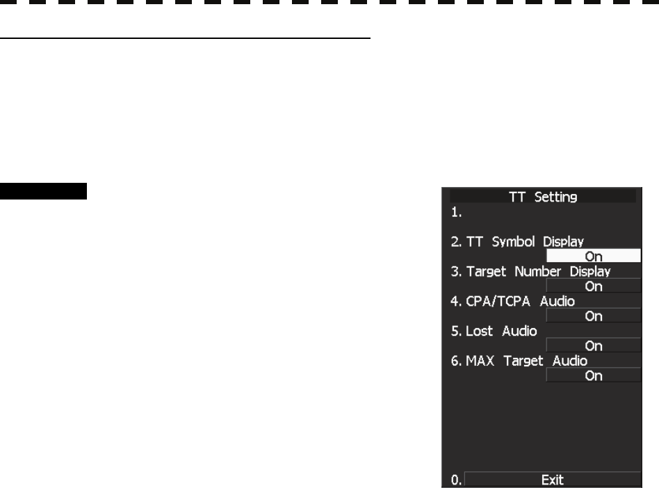
5─9
TT symbol display setting (TT Symbol Display)
Turn on or off (ON / OFF) the TT symbol display.
This function can be used only when the AIS display function (optional) is on.
This function cannot be used when the AIS display function (The TT display function cannot be deactivated if
only TT is used without using the AIS function).
Data is saved even though the TT display is turned off by this function.
Refer to Section 5.3 “AIS OPERATION” for the AIS display function.
Procedure 1 Press the [TT MENU] key.
2 Press the [1] key.
TT Setting menu opens.
3 Press the [2] key.
TT Symbol Display is turned on or off.
ON : Enables the TT symbol display function.
OFF : Disables the TT symbol display function.
* Software button ⑨ located at the other ship's information area in Section 2.3.6 is also available for
switching.
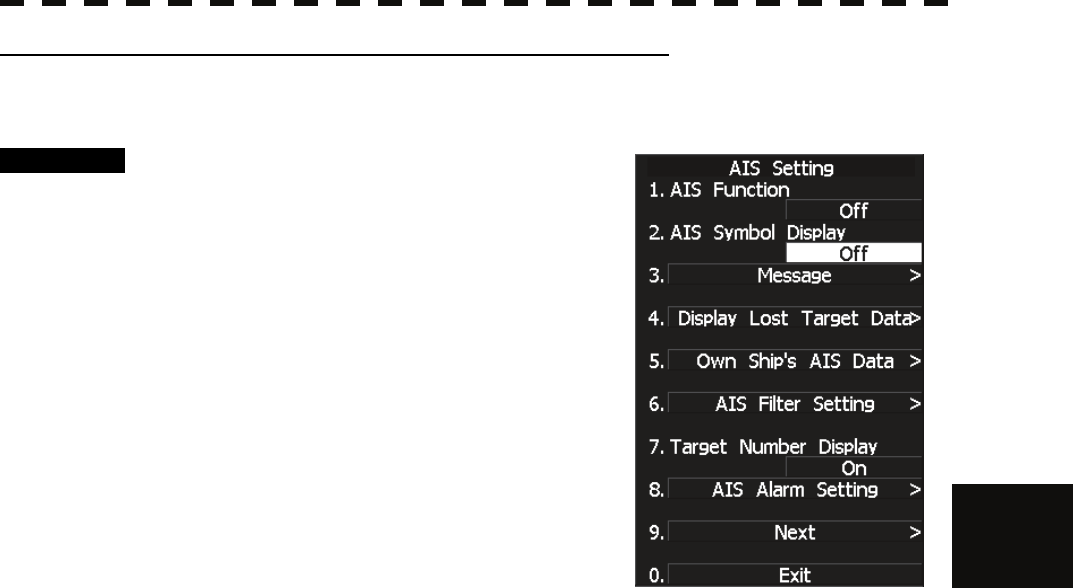
5.1 PREPARATION
5─10
5
yy
yyy
Setting AIS Symbol Display Function (AIS Symbol Display)
Switch ON or OFF to set the AIS symbol display function.
Procedure 1 Press [TT MENU] key.
Press [2] key.
The AIS Setting menu will appear.
2 Press [2] key.
The AIS Symbol Display is switched between
ON and OFF.
ON: Enables the AIS symbol display function.
OFF: Disables the AIS symbol display function.
* Software button ⑩ located at the other ship's information area in Section 2.3.6 is also available for
switching.
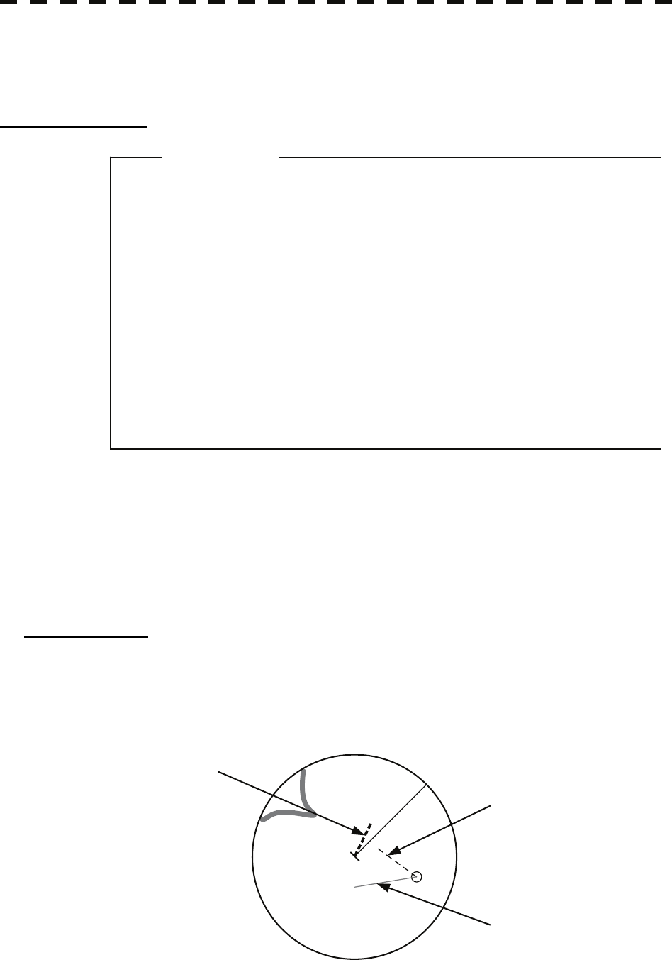
5─11
5.1.3 TT Data Display
(Refer to Example of Display in Section 2.1 “EXAMPLE OF DISPLAY.”)
Display of Vectors
A vector to represent a target’s predicted position can presented in the True vector or Relative vector mode. In
each mode, a vector length can be freely changed for a time interval of 1 to 60 minutes.
The True and Relative vector can be switched by using software button ① located at the other ship's
information area in Section 2.3.6.
[I] Vector Mode Selection
True Vector Mode
In the true vector mode, the direction of a target vector indicates the true course of the target and its vector
length is proportional to its speed.
In this mode, own ship’s vector is displayed as shown below.
In this mode, the movements of other ships around own ship can be accurately and easily monitored.
However, no CPA RING can appear in this mode.
The relative vector is
not displayed
True vector
Own ship’s position HL
z When a target or own ship changes a course, or when
a target is acquired, its vector may not reach a given
level of accuracy until three minutes or more has
passed after such course change or target
acquisition.
Even if three minutes or more has passed, the vector
may include an error depending upon the tracking
conditions.
Atte
n
t
i
o
n

5.1 PREPARATION
5─12
5
yy
yyy
Relative Vector Mode
In displaying the relative vector of a target, press the [VECT R/T] key to select the Relative Vector mode.
The relative vector does not represent the true motion of the target, but its relative relation with own ship.
This means that a target with its relative vector directed to own ship (passing through the CPA LIMIT ring) will
be a dangerous target. In the Relative Vector mode, it can be seen at a glance where the CPA LIMIT of the
dangerous target is.
The true vector is
not displayed
Relative vector
CPA ring
HL
Therefore, the TRUE/REL mode shall optionally be used for the purpose of observation: the TRUE vector
mode for grasping the true aspect of a target, and the REL vector mode for grasping a target’s closest point of
approach (CPA)
[II] Vector Length: VECTOR TIME
The vector length of a target is proportional to its speed, and the vector time can be switched in a range of 1 to
60 minutes by used for ten-key.
The diagram below illustrates a vector length of a target for six minutes, and the tip of the vector represents the
target’s position expected to reach six minutes later.
Refer to Section 5.1.7 “Setting Vectors (Vector Time)” for how to change the vector time.
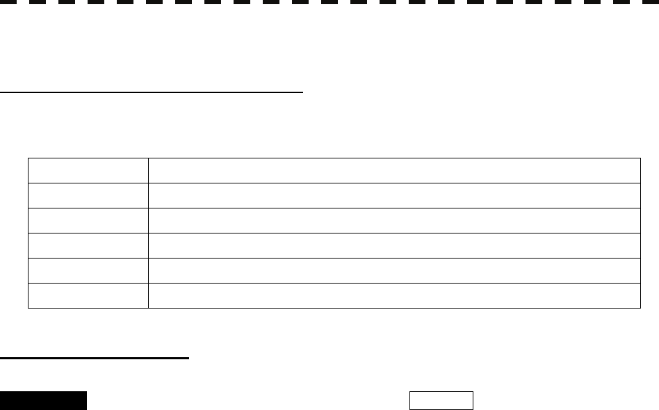
5─13
5.1.4 Cursor Modes (Cursor)
Types and Functions of Cursor Modes
The types of cursor modes are listed in the table below. To use the function of a cursor mode, move the cursor
onto the PPI object and press the [ENT] key.
Mode Function
ACQ TT Enables the target tracking function to acquire a target in manual mode.
ACT AIS Activates AIS targets, deactivates AIS target and sets a point filter.
TGT Data Select or deselect a tracking or AIS target whose numerical data is to be displayed.
Cancel Cancels a target tracking.
Mark Puts a temporary mark.
Change of Cursor Mode
Procedure 1 Move the cursor to the cursor mode Cursor (software button ①
located at the top right corner of the radar display described in Section
2.3.3), and press the [ENT] key.
The selected cursor mode will be shown at the cursor mode (software button ② located
at the top right corner of the radar display described in Section 2.3.3).
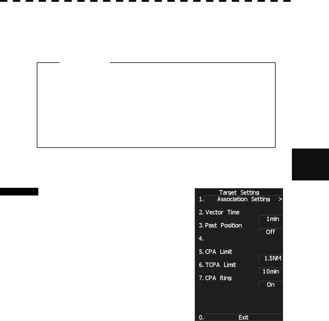
5.1 PREPARATION
5─14
5
yy
yyy
5.1.5 Setting Collision Decision Criteria (CPA/TCPA Limit)
For details on each operation, see 3.4 BASIC OPERATION and 4 MEASUREMENT OF RANGE AND
BEARING.
Set and check collision decision criteria before operating the TT system.
Procedure 1 Press [TT MENU] key.
2 Press [3].
The TT Setting menu will appear.
3 Press [5].
The ten-key screen will appear.
4 Select the value to be set pressing the
numeric key, and press [ENT].
The selected CPA Limit value will be
determined.
5 Press [6].
The ten-key screen will appear.
6. Select the value to be set pressing the numeric key, and press [ENT].
The selected TCPA Limit value will be determined.
z Set the optimum values of collision decision
conditions, depending upon vessel type, water area,
weather and oceanographic conditions.
(For the relations between those conditions and
alarms, refer to Section 5.5 “ALARM DISPLAY.”)
Attention
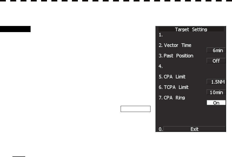
5─15
5.1.6 Setting CPA Ring (CPA Ring)
Procedure 1 Press [TT MENU] key.
2 Press [3].
The TT Setting menu will appear.
3 Press [7].
The setting of CPA Ring will change between
ON and OFF.
ON: Displays the CPA ring.
OFF: Hides the CPA ring.
While the CPA ring is displayed, CPA RING
is shown at the lower right of the radar display.
While the distance of the specified CPA Limit
value is used as the radius, the CPA ring is
displayed with a white circle of which center is the own ship’s position.
Note: The CPA ring is not displayed when the true (T) vector mode is selected.
* The CPA ring switch to Display or Hide within software button ⑦ located at the bottom right corner of the
radar display described in Section 2.3.4.
5.1 PREPARATION
5─16
5
yy
yyy
5.1.7 Setting Vectors (Vector Time)
Vector time can be set in minutes in the range 1 to 60 min.
A true vector mode or relative vector mode can be selected.
Setting vector time on the display
Procedure 1 Move the cursor to the target vector time setting (Software button ②
located at the other ship's information area in Section 2.3.6), and press
the [ENT] key.
The Vector Time value input screen will appear.
2 Use number keys, input a vector length, and press the [ENT] key.
The inputted vector length is confirmed.
Setting vector time using the multi-dial [MULTI]
Procedure 1 Press the [MULTI] dial several times to activate the Vector mode.
Vector will be displayed in the multi-dial mode (⑭ located at the bottom left corner of
the radar display described in Section 2.3.2).
2 Turn the [MULTI] dial to set the vector time.
Setting vector mode [VECT R / T]
Procedure 1 Press the [VECT R / T] key.
The current vector mode T (true vector) or R (relative vector) will be displayed in
the target vector display true / relative switching (software button ① located at the other
ship's information area in Section 2.3.6).
The vector mode is switched between T (true vector) and R (relative vector) each
time the button is pressed.

5─17
5.1.8 Setting the GPS antenna location
Set the GPS antenna location. Set offset ranges in longitudinal direction and latitudinal direction from the own
ship's reference position.
For the setting procedure, refer to Section 7.1.6 “Setting of CCRP/Antenna/GPS Antenna Position (CCRP
Setting).”
z If offset ranges are not set correctly, AIS symbols and
radar echoes may be displayed shifted.
z When offset ranges are set, latitude and longitude
data received from the GPS is offset, and the offset
data is displayed as the latitude and longitude of own
ship’s position.
Attention
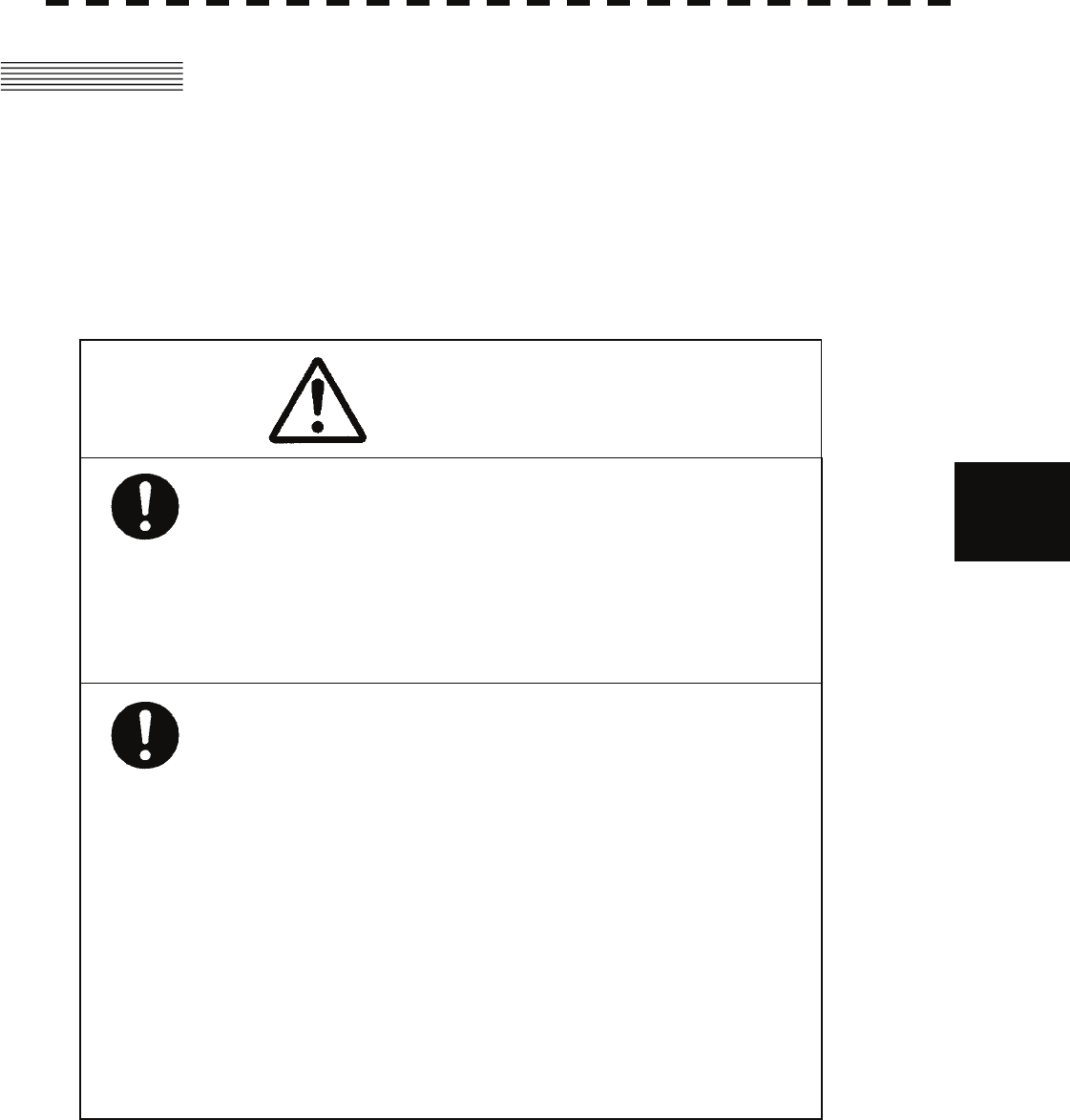
5.2 TT OPERATION
5─18
5
yy
yyy
5.2 TT OPERATION
This section explains how to use the target tracking (TT) functions.
Each function is available only when the target tracking (TT) option is installed.
The functions automatically track a target, and store/display vectors as the course and speed.
They calculate CPA and TCPA, and issue an alarm.
The target tracking (TT) function can track up to 30 ships.
Automatic acquisition/activate zone can be set for automatic acquisition.
When the power is turned off or the transmit/standby mode is activated, tracking data is erased from memory.
Caution
Use the radar only as a navigation aid.
The final navigation decision must always be made by
the operator him/herself.
Making the final navigation decision based only on the
radar display may cause accidents such as collisions
or running aground.
Use target tracking function only as a navigation aid.
The final navigation decision must always be made by
the operator him/herself.
Making the final navigation decision based only on
tracking target information may cause accidents.
Tracking target information such as vector, target
numerical data, and alarms may contain some errors.
Also, targets that are not detected by the radar cannot
be acquired or tracked.
Making the final navigation decision based only on the
radar display may cause accidents such as collisions or
running aground.
5─19
5.2.1 Acquiring Target [ACQ]
Target acquisition can be performed on two modes, AUTO and MANUAL, and both modes can be used at the
same time.
Automatic Acquisition [AUTO]
Procedure 1 Press the [AZ] key.
Automatic acquisition will be started. The mark “ ” and target ID number are put to
an acquired target, and they move together with the target. The vectors are displayed
within one minute.
2 Press the [AZ] key again.
Automatic acquisition will be turned off, and automatic acquisition/activate zone
disappears from the radar display. However, automatically acquired ships are
continuously tracked.
For automatic acquisition/activate zone to be called by using the [AZ] key, refer to
“Setting Automatic Acquisition Key Assignment (Set AZ Key)” on the next page.
z If untracked targets intrude into automatic
acquisition/activate zone in the conditions that
maximum number of targets is under tracking, the
targets acquired automatically will be cancelled in
the order of lower levels of danger.
Attention
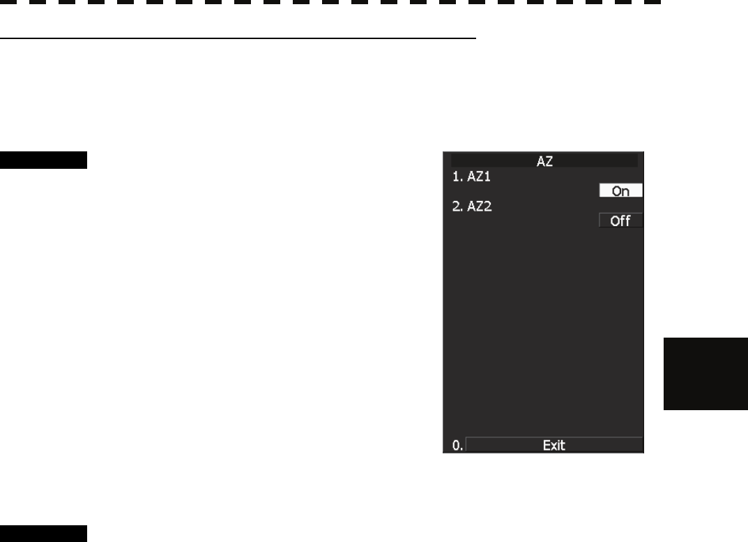
5.2 TT OPERATION
5─20
5
yy
yyy
Setting Automatic Acquisition Key Assignment (Set AZ Key)
This section explains how to set automatic acquisition/activate zone that is to be assigned to the [AZ] key.
The setting enables the operator to select ON/OFF for a generally used automatic acquisition/activate zone by
simply operating the [AZ] key on the control panel.
Procedure 1 Press [TT MENU] key.
Press [5].
Press [3].
Press [1].
AZ menu will appear.
ON: Turns on automatic acquisition/activate
zone when the [AZ] key is pressed.
OFF: Does not turn on automatic
acquisition/activate zone when the [AZ]
key is pressed.
The same function also as RADAR Alarm (Sector Alarm) can be given.
Procedure 1 Press [TT MENU] key.
Press [5].
Press [3].
Press [2].
* The setting method is the same as the method of automatic acquisition/activate zone.
For the creation method of sector alarm, refer to [IV] “Make Sector Alarm (Make
Sector Alarm)” in Section 3.5.21 “Radar Alarm (Radar Alarm).”
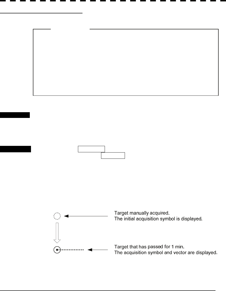
5─21
Manual Acquisition [MANUAL]
Procedure 1 Move the cross cursor mark onto the target to be acquired, and press the
[ACQ] key.
The target will be acquired. The initial acquisition mark and target ID number are put to
the acquired target, and the vectors are displayed within one minute.
Alternative 1 Press the CURSOR button at the upper right of the radar display
several times until ACQ TT appears.
The TT acquisition mode is set as the cursor mode.
2 Move the cross cursor mark onto the target to be acquired, and press the
[ENT] key.
The target will be acquired. The initial acquisition mark and target ID number are put to
the acquired target, and the vectors are displayed within one minute.
When using only the manual acquisition mode alone, press the [AZ] key to turn off the
automatic acquisition mode.
Use of Automatic and Manual Acquisition Modes [ACQ AUTO] / [ACQ MANUAL]
Use the manual acquisition mode while the automatic acquisition mode is on.
Manually acquire the target to which particular attention should be paid, and get the other targets automatically
acquired. If a new target appears exceeding the maximum number of targets, the manually acquired target is
displayed even in the background until it gets out of the display. However, automatically acquired targets are
canceled starting far distance from own ship.
z If more targets are acquired manually in the
condition that the maximum number of targets are
under tracking, the targets under tracking will be
cancelled in the order of lower level of danger in
order to track the manually acquired targets.
Attention
5.2 TT OPERATION
5─22
5
yy
yyy
5.2.2 Canceling Unwanted Targets
Unwanted targets can be canceled one by one in the following cases:
• Tracking is no longer necessary for targets with which vectors/symbols are displayed after being acquired
and tracked.
• The number of vectors on the radar display needs to be reduced for easy observation.
When targets are to be re-acquired from the beginning, all the current vectors can also be canceled.
Canceling targets one by one
Procedure 1 Move the cross cursor mark onto the target to be canceled.
2 Press the [TGT CNCL] key.
The target’s vectors and symbols will disappear, and only the radar video remains.
Alternative 1 Press the CURSOR button at the upper right of the radar display
several times until ACQ TT appears.
The TT acquisition mode is set as the cursor mode.
2 Move the cross cursor mark onto the target to be acquired, and press the
[CLR/INFO] key.
The target’s vectors and symbols will disappear, and only the radar video remains.
Canceling all targets collectively
Procedure 1 Hold down the [TGT CNCL] key.
The vectors and symbols of all the targets will disappear, and only the radar videos
remain.
Note: When all the targets have been canceled, the system stops tracking them. Thus, you need to re-acquire
targets in manual or automatic acquisition mode. Do not cancel all the targets unless otherwise
required.
5─23
5.2.3 Tracking Target Data Display [TGT DATA]
Type of Data Display
Target Data
Target identification (TT ID) ID number of the target
True bearing: BEARING 0.1° unit
Range: RANGE 0.01 NM unit
True course: COURSE 0.1° unit
True speed: SPEED 0.1 knot unit
Closest point of approach (CPA) 0.01 NM unit
Time to CPA (TCPA) 0.1 min unit
Bow crossing range (BCR) 0.01 NM unit
Bow crossing time (BCT) 0.1 min unit
The target for which its numeric data is displayed is marked with a symbol “ ” to distinguish from other
targets.
If a target’s data is displayed, but without the symbol “ ”, such a target exists outside the currently
displayed radar display.
z When a target or own ship changes its course, or when a new
target is acquired, its vector may not reach a given level of
accuracy until three minutes or more has passed after such
course change or target acquisition.
Even if three minutes or more has passed, the vector may
include an error depending upon the. tracking conditions.
Attention

5.2 TT OPERATION
5─24
5
yy
yyy
[I] Method of Displaying Target Data [TGT DATA]
Procedure 1 Move the cross cursor mark onto the target for which numeric data is to
be displayed, and press the [TGT DATA] key.
Or, set the cursor mode to TGT Data, place the cross cursor over the
target whose numerical data is to be displayed, and press the [ENT] key.
Then, the data of the designated target will appear, it will be marked with a symbol “ ”.
The target data will remain on the radar display until the target is lost and its vector
disappears, or until another target is designated.
If a target with the mark “ ” is designated, only its true bearing (BEARING) and range
(RANGE) will appear until its vector appears.
[II] Canceling numerical data display (CNCL Data)
Procedure 1 Set the cursor mode to TGT Data, place the cross cursor over the tracked
target whose numerical data is to be displayed, and press the [CLR/INFO]
key.
Numerical data display is canceled.
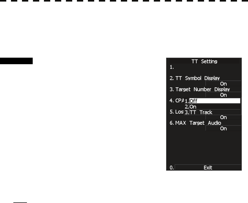
5─25
5.2.4 Displaying Target ID No. (Target Number Display)
A target ID number is a value displayed beside the acquisition symbol when a target is acquired.
These numbers are assigned to targets in acquisition order. The numbers 1 to 30 are automatically assigned.
Each target is identified by the assigned ID number until it is lost or its acquisition is canceled.
Procedure 1 Press [TT MENU] key.
2 Press [1] key.
The TT Setting menu will appear.
3 Press [3] key.
The Target Number Display is switched ON or
OFF.
ON: Displays target ID numbers.
OFF: Hides target ID numbers.
Target TRACK:
Displays target ID number with target
track.
If there are many tracking targets and their
symbol display is confusing, set Target Number
Display to OFF to view the radar display easily.
Note: An ID number is always displayed for only targets with which numeric data is displayed.
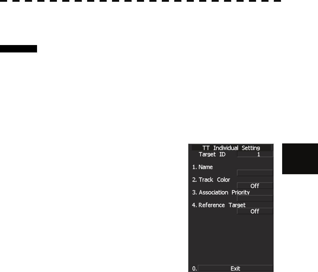
5.2 TT OPERATION
5─26
5
yy
yyy
5.2.5 Input of target information (TT Individual Setting)
This radar enables name inputs and target track color changes for individual TT targets acquired.
Procedure 1 Turn OFF the cursor mode.
Software button ① located at the top right corner of the radar display described in
Section 2.3.3 is available to change the cursor mode.
2 Place the cursor over the target and then press [CLR/INFO] key.
The TT Individual Setting INFO screen opens.
* This function is available only when the cursor mode is set to OFF.
Target information screen
Item overview
Target ID : Target ID currently selected.
Name : The name of the target. It is
blanked in the initial status. The
user is to enter a name.
Track Color : Determines a target track color.
Association Priority :
Specify whose target information
is to be displayed between an AIS
target and a TT target when an
association is made.
Reference Target :
On : Set this target as a reference
target.
Off : Stop using this target as a
reference target.
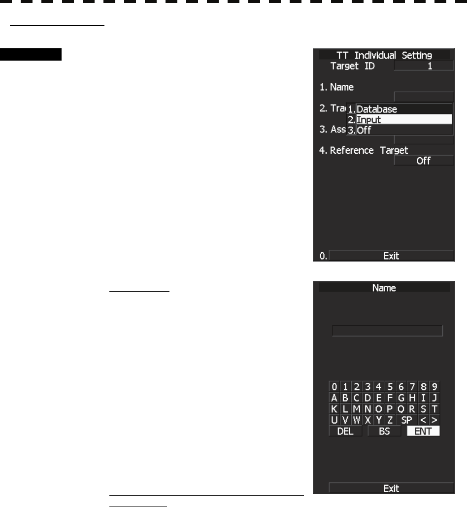
5─27
Name entry (Name)
Procedure 1 While the TT Target INFO screen is
open, press [1] key.
2 For the entry of a new name
→ 2. INPUT
For the selection of a name from names
that have already been entered
→ 1. DATA BASE.
For new entry
Selecting INPUT displays the screen shown
below.
After making an entry, place the cursor over
[ENT] key and then press it.
When the name entered with INPUT is changed
to a target name, it is saved in DATA BASE.
* Up to eight characters can be entered as a
name.
For calling a name from the names that have
been entered
Selecting DATA BASE lists INPUT names that have already been entered. From the list,
select a name you want to use.
* Names for 32 ships can be saved in DATA BASE.
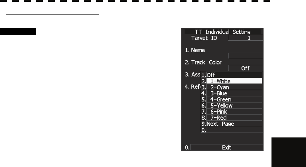
5.2 TT OPERATION
5─28
5
yy
yyy
Track Color Setting (Track Color)
Procedure 1 While the TT Target INFO screen is
open, press [2] key.
2 Pressing numeric key(s), select a color
number you want to set.
Colors selectable with Track Color are colors
that have been set within the TT Track Setting.
When colors are set, individual colors can be set
for the 1th to 20th.
On this screen, selection of the 1st track is to
select CYAN.
For target tracks, up to 20 ships can be displayed.

5─29
5.2.6 Reference Target (Reference)
This equipment can calculate and display the speed of own ship by tracking a target whose position is fixed
with respect to the ground and by setting this target as a reference target.
z The reference target function is to be used if the own ship's
speed cannot be displayed normally due to trouble such as a
speed sensor malfunction. Do not use the reference target
function except in emergencies.
z If the speed or course of the own ship is changed or a new
reference target is set, the displayed speed may take 3 minutes
or more to reach the specified speed after the speed / course
change or the setting.
Even after 3 minutes or more has passed, the speed may differ
from the specified speed depending on the tracking condition.
z If a large radar echo such as a land target is set as a reference
target, the vectors of the speed and other tracking targets will
not be displayed correctly and may cause an accident.
z If a sailing ship is set as a reference target, the vectors of the
speed and other tracking targets will not be displayed correctly
and may cause an accident.
z If the REF. is selected for the speed sensor, the AIS function
cannot be turned on.
z If the reference target is lost or the target tracking function is
stopped, the speed sensor is placed in manual mode MAN .
z The loss of a reference target may have a major impact on the
accuracy of the results for true speed and true course of the
target and that own speed will be degraded.
z The reference targets are only used for the calculation of true
speed.
Attention

5.2 TT OPERATION
5─30
5
yy
yyy
Procedure 1 Acquire a target whose position if fixed with respect to the ground.
2 Set the cursor mode to OFF.
3 Place the cursor over the tracked target and press the [CLR/INFO] key.
4 Target information menu is displayed.
5 Press the [4] key.
ON : Set this target as a reference target.
OFF : Stop using this target as a reference target.
When ON is selected, the speed device activates the reference target function.
Then symbol “○R” is displayed when the reference target is set.
Only one target can be set as a reference target.
When a new reference target is created, the previous reference target is deleted.
When OFF is selected, the speed device deactivates the reference target function and other
functions become available.
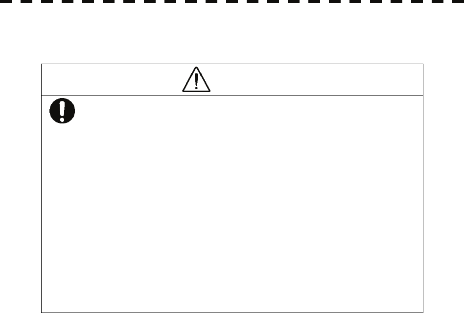
5─31
5.2.7 TT Test Menu
CAUTION
Target Tracking Function Test is provided to test if
the target tracking function is operating normally.
Thus, do not use the function except when you
test the target tracking function.
In particular, if this mode is used during
navigation, pseudo targets appear on the radar
display, which may be confused with the actual
targets. Do not use this mode during navigation.
Otherwise, this may cause accidents.
The following simulation to be used for TT can be referred to and modified:
[I] Test Video: Test video for use in checking the operation of the target detection circuit.
[II] TT Simulator: Pseudo targets are generated on the radar display to check whether the TT
functions are operating normally.
[III] Status: Displays the TT status.
[IV] Gate Display: Gate size to acquire and track targets.
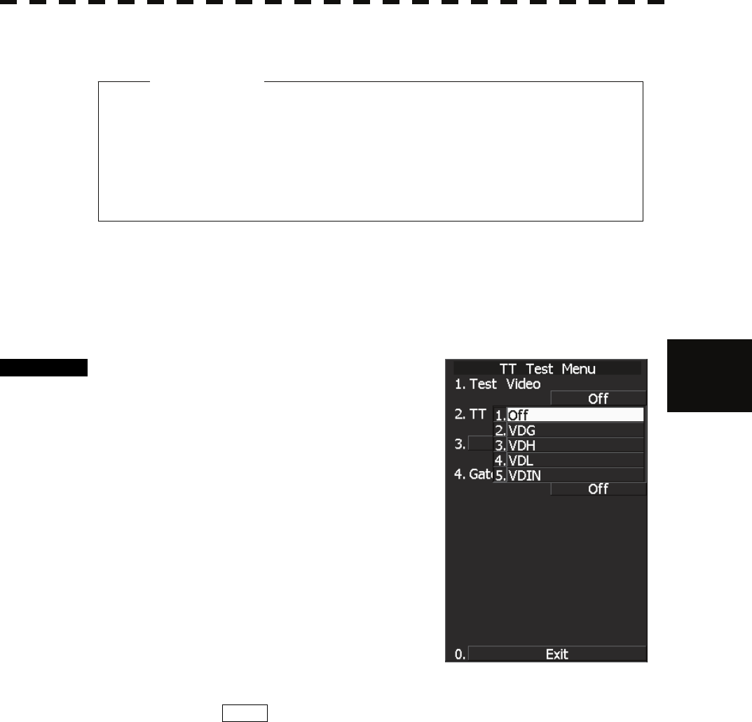
5.2 TT OPERATION
5─32
5
yy
yyy
[I] Test Video
Test Video is used to check whether the video signals under target acquisition and tracking are inputted to and
processed in the target processing circuit normally.
However, it is sufficient to check that VDH in TEST VIDEO is displayed.
The start of the Test Video mode is available only in the Standby mode.
Procedure 1 Press [STBY] key.
The equipment will enter the standby state.
2 Press [TT MENU] key.
Press [6] key.
The TT Test Menu will appear.
3 Press [1] key.
The Test Video setting screen will appear.
4 Press a numeric key to select a video
signal you want to set.
The selected test video will be set.
The test video is displayed in the background of
the radar display.
In general, VDH is sufficient for target display checks in test video mode.
If any target displayed clearly in the radar display is not displayed in the Test Video mode, the target detection
circuit of the TT system may have a trouble.
z TEST VIDEO may not appear for targets that are not
acquired nor tracked, or if the [GAIN] and [SEA]
controls are adjusted properly
A
tt
e
nti
o
n
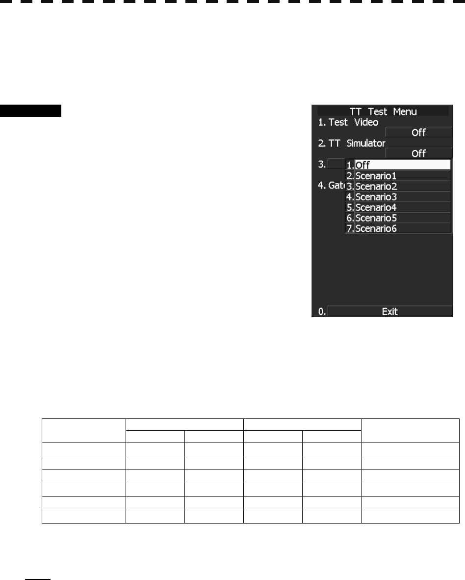
5─33
[II] Target Tracking Simulator
Pseudo targets can be generated in certain known positions to check whether the TT processing circuits are
operating normally. Since the pseudo targets move depending on known parameters, the values for these
pseudo targets can be compared with the known value if the pseudo targets are acquired and tracked, and
displayed. Thus, it can be checked if the TT system is operating normally.
Procedure 1 Press the [STBY] key.
The equipment will enter the standby state.
2 Press [TT MENU] key.
Press [6] key.
The TT Test Menu will appear.
3 Press [2] key.
Choices for the TT simulator (TT Simulator) are
displayed.
4 Select the simulator to be set, pressing
the numeric key.
The selected simulator will be set.
5 Press the [TX/PRF] key.
The simulator will be activated and generate pseudo targets. The characters "X" at the
bottom of the radar display blinks indicating that the simulation mode is active.
TT simulator/scenario
TARGET START POINT TARGET END POINT
SCENARIO DISTANCE BEARING DISTANCE BEARING TARGET SPEED
1 3.2NM
10° 1NM 90° 20kts
2 6NM
0° 0NM 0° 10kts
3 6NM
every 18° 1NM every 18° 10kts
4 6NM
45° 1NM 45° 105kts
5 6NM
45° 6NM 150° 20kts
6 6NM
45° 6NM 150° 20kts
Note: Set the ship's heading bearing to 0º and the own ship speed to 0 kn while the simulator is operating.
When the range between own ship and the pseudo target is 0, the target will disappear.

5.2 TT OPERATION
5─34
5
yy
yyy
Exit 1 Press the [STBY] key.
The equipment will enter the standby state.
2 Press [2] key while the TT Test Menu is open.
Choices for the TT simulator (TT Simulator) are displayed.
3 Press [1] key to select OFF.
The TT Simulator is turned off.
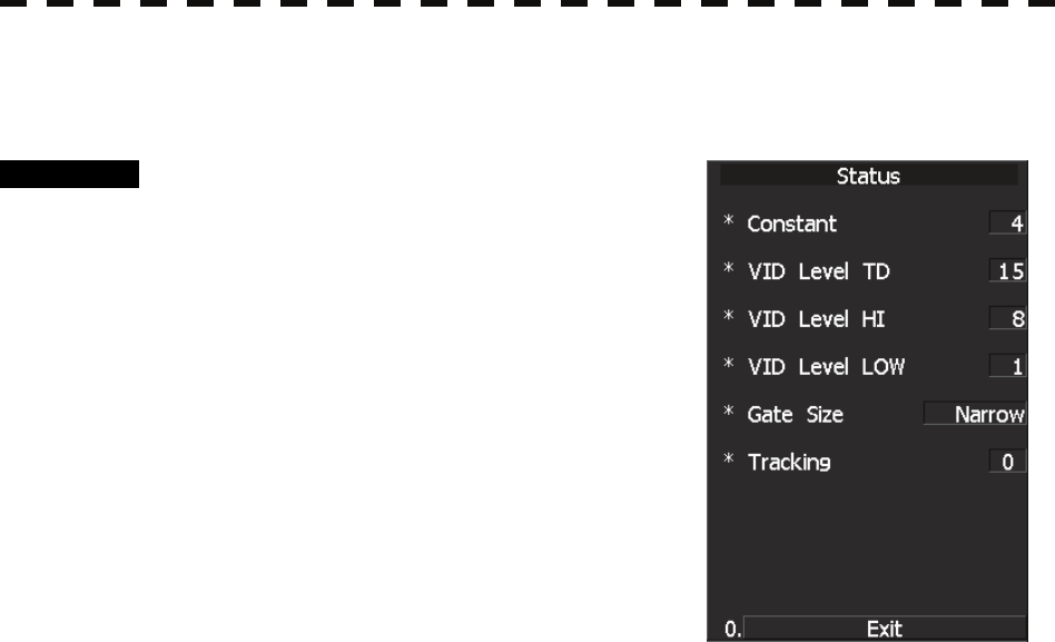
5─35
[III] Status
The current TT status will appear.
Procedure 1 Press [TT MENU] key.
The TT Menu will appear
Press [6] key.
The TT Test Menu will appear.
2 Press [3] key.
The Status screen will appear..
*Constant: Vector response
*Video Level TD: Threshold value used for
tracking
*Video Level HI: VD threshold value used
for automatic
acquisition/activate zone
*Video Level Low: Unused
*Gate Size: Size of gate used for tracking
*Tracking: Number of targets currently acquired
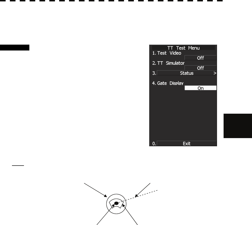
5.2 TT OPERATION
5─36
5
yy
yyy
[IV] Gate Display
The gate displays an area monitoring a target using the TT function. This radar equipment allows the gate size
to change automatically according to target distance and size. User can check the gate size using the following
function.
Procedure 1 Press [TT MENU] key.
Press [6] key.
The TT Test Menu will appear.
2 Press [4] key.
The gate display mode is switched.
ON: Gate is displayed
OFF: Gate is not displayed
3 The gate displays data of a target you
want to check using the cursor and
[TGT DATA] key. (See Section 5.3.6
“Displaying Numeric Data of AIS
Targets (TGT DATA).”)
The data is displayed, and the gate is displayed
around the TT symbol in green.
Note: The TT function can display the gate of two targets simultaneously.
TT symbol Vector
Echo Gate (displayed in green)
5─37
5.3 AIS OPERATION
5.3.1 Restrictions
* The AIS function is optional for non-MED ships.
Use of this function requires AIS I/F (option).
There are the following limitations on use of the AIS function,
system, and operation:
[I] This system can display up to a total of 130 targets.
Of which, up to 30 activated targets can be displayed.
There are 3 types of filters for controlling sleeping target
display.
(Refer to Section 5.3.8 “Setting AIS Filter (AIS Filter Setting)”.)
[II]
The following restrictions are placed on use of the AIS function.
• The AIS function is unavailable in the following cases:
MAN is selected for the speed sensor.
The current offset (Set/Drift Setting) is set while LOG or
2AXW is selected for the speed sensor.
The GPS geodetic system is used except WGS-84.
• LOG or 2AXW cannot be selected for the speed
sensor in the following case:
The AIS function is turned on and the current offset
(Set/Drift Setting) is selected.
• MAN cannot be selected for the speed sensor in the
following case:
The AIS function is On.
• Current offset (Set/Drift Setting) cannot be turned On in
the following case:
LOG or 2AXW is selected for the speed sensor while
Attention

5.3 AIS OPERATION
5─38
5
yy
yyy
5.3.2 Initial Setting
This section explains the initial setting for using the AIS function.
Setting the GPS antenna location
Set the GPS antenna location. Set offset ranges in longitudinal direction and latitudinal direction from the
own ship's reference position.
For the setting procedure, refer to Section 7.1.6 “Setting of CCRP/Antenna/GPS Antenna Position (CCRP
Setting).”
Setting collision decision criteria (CPA Limit/TCPA Limit)
The collision decision criteria for the TT function are applied to the AIS function.
For the setting procedure, refer to Section 5.1.5 “Setting Collision Decision Criteria (CPA/TCPA Limit).”
Note that the same collision decision criteria must apply to TT.
z If offset ranges are not set correctly, AIS symbols and
radar echoes may be displayed shifted.
z When offset ranges are set, latitude and longitude
data received from the GPS is offset, and the offset
data is displayed as the latitude and longitude of own
ship’s position.
Attention
z Set the optimum values of collision decision
conditions, depending upon vessel type, water area,
weather, and oceanographic conditions.
Attention
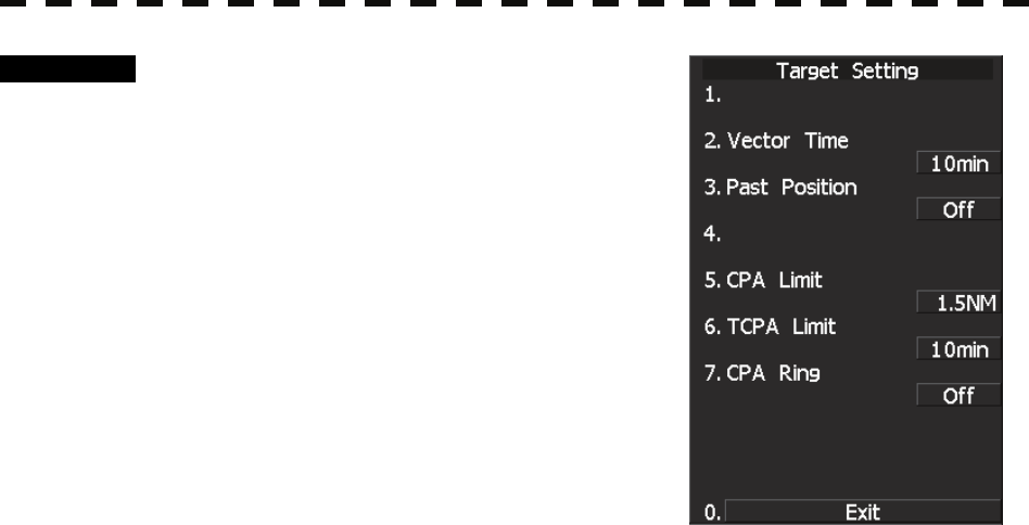
5─39
Procedure 1 Press [TT MENU] key.
2 Press [3] key.
The Target Setting Menu will appear.
3 Press [5] key.
The ten-key screen will appear.
4 Using numeric keys, enter the CPA
value you want to set, and then press
[ENT] key.
The entered CPA Limit value is determined.
5 Press [6] key.
The ten-key screen will appear.
6 Using numeric keys, enter the TCPA value you want to set, and then
press [ENT] key.
The entered TCPA Limit value is determined.
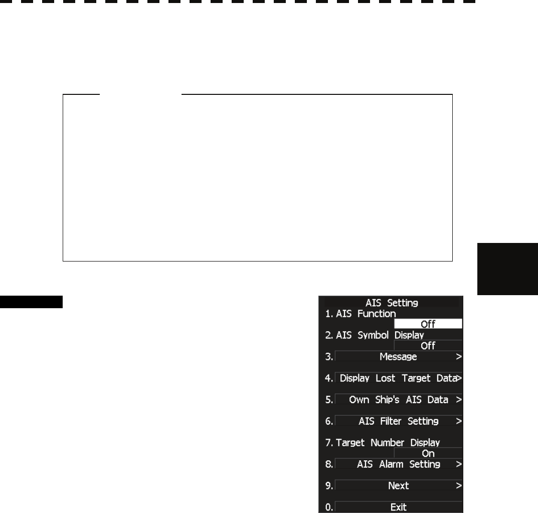
5.3 AIS OPERATION
5─40
5
yy
yyy
5.3.3 Setting AIS Display Function (AIS Function)
Switch the AIS symbol display function to ON/OFF.
Procedure 1 Press [TT MENU] key.
Press [2] key.
The AIS Setting menu will appear.
2 Press [1] key.
The AIS Function is switched between ON and
OFF.
ON: Enables the AIS display function.
OFF: Disables the AIS display function.
* Software button ⑧ located at the other ship's information area in Section 2.3.6 is also available to switch
the display functions.
* Note that turning OFF this function switches all AIS display functions to OFF.
z When the AIS display function is set to OFF, no AIS
symbols are displayed.
z The AIS display function itself is turned OFF.
z Once the AIS display function is set to OFF, it is not
automatically switched to ON even if a dangerous
target exists.
Attention
5─41
5.3.4 Activating AIS Targets (Activate AIS)
Activate an AIS target, and display the target’s vector and make a collision decision.
Manual activation
Activate an AIS target*1 in manual mode to display the vector and HL.
Procedure 1 Press the CURSOR button at the upper right of the radar display
several times until ACT AIS appears.
The cursor mode is set to the AIS activation mode.
2 Move the cross cursor mark onto the inactive AIS target that is to be
activated*1, and press [ENT] key.
The selected AIS target will be activated*1.
Automatic activation
Activate an AIS target in automatic mode to display the vector and heading line.
When the automatic activation function is used, AIS targets are automatically activated when they go into the
automatic activation zone. The automatic activation zone is identical to the automatic acquisition zone (AZ)
used for target tracking. For the zone setting, refer to Section 3.5.20 “Auto Acquisition” and Section 5.2.1
“Acquiring Target [ACQ].”
Reference If an AIS target is activated but the vector is not displayed, refer to “Setting AIS Symbol Display
Function (AIS Symbol Display)” in Section 5.1.2 “Definitions of Symbols.”
*1 For activation of targets, refer to “Types and Definitions of AIS Target Symbols” in Section 5.1.2
“Definitions of Symbols.”
5.3 AIS OPERATION
5─42
5
yy
yyy
z The operation above is effective only for active
targets.
5.3.5 Deactivating AIS Targets (Deactivate AIS)
Deactivate an AIS target*2 and clear the display of the vector and HL.
Procedure 1 Press the CURSOR button at the upper right of the radar display
several times until CANCEL appears.
The cursor mode is set to the deactivation mode.
2 Move the cross cursor mark onto the active AIS target that is to be
deactivated*2, and press [ENT] key.
The selected AIS target will be deactivated*2 .
Alternative 1 Press the CURSOR button at the upper right of the radar display
several times until ACT AIS appears.
The cursor mode is set to the AIS activation mode.
2 Move the cross cursor mark onto the inactive AIS target that is to be
activated*1, and press [CLR/INFO] key.
The selected AIS target will be deactivated*2
*2 For deactivation of targets, refer to “Types and Definitions of AIS Target Symbols” in Section 5.1.2
“Definitions of Symbols.”
Attention

5─43
5.3.6 Displaying Numeric Data of AIS Targets (TGT DATA)
Numerical data for a specified AIS target is displayed.
Types of numeric data displayed
Display items
y Navigation information
BRG (true bearing) 0.01° unit
RANGE 0.01nm unit
COG (course over ground) 0.1° unit
SOG (speed over ground) 0.1knot unit
CPA (closest point of approach) 0.1nm unit
TCPA (time to CPA) 0.1min unit
HDG (heading bearing) 1° unit
ROT (course change speed) 0.01°/min
y Destination and location information
Destination
Estimated time of arrival
L/L (latitude/longitude) 0.0001’ unit
Position fixing device
RAIM
Position fixing accuracy
y Ship information
NAME (ship name) Up to 20 characters
CALL SIGN Up to 7 characters
MMSI Up to 9 characters
IMO number
Navigation status
y AtoN information
AtoN class
AtoN type
If missing is displayed in place of the numeric information of ROT, the radar is receiving the AIS data which
cannot is displayed. In this case, you can only trust the turning direction which is indicated by the turn indicator.
The turn indicator is displayed on the AIS symbol as the line perpendicular to the heading direction. (Refer to
Section 5.1.2 "Types and Definitions of AIS Target Symbols")
If the numeric information of SOG or STW is 102.2kn, the target ship's speed is 102.2kn or over. Then the
system cannot calculate CPA and TCPA. Therefore, missing is indicated in the CPA and TCPA information.
5.3 AIS OPERATION
5─44
5
yy
yyy
Displaying numeric data
Procedure 1 Press the CURSOR button at the upper right of the radar display
several times until
TGT DATA appears.
The cursor mode is set to the numeric data display mode.
2 Move the cross cursor mark onto the active AIS target for which numeric
data is to be displayed, and press [ENT] key.
The values of the selected AIS target will appear on the right side of the radar display.
The mark is displayed around the symbol.
Reference: If the values are displayed but the mark . is not on the radar display, the target is outside the
radar display.
Clearing numeric data
Procedure 1 Press the Cursor button at the upper right of the radar display several
times until TGT Data appears.
The cursor mode is set to the numeric data display mode.
2 Move the cross cursor mark onto the active AIS target for which numeric
data is to be cleared, and press [CLR] key.
The values of the selected AIS target will be cleared from the right side of the radar
display, and the mark displayed around the symbol will also disappear.
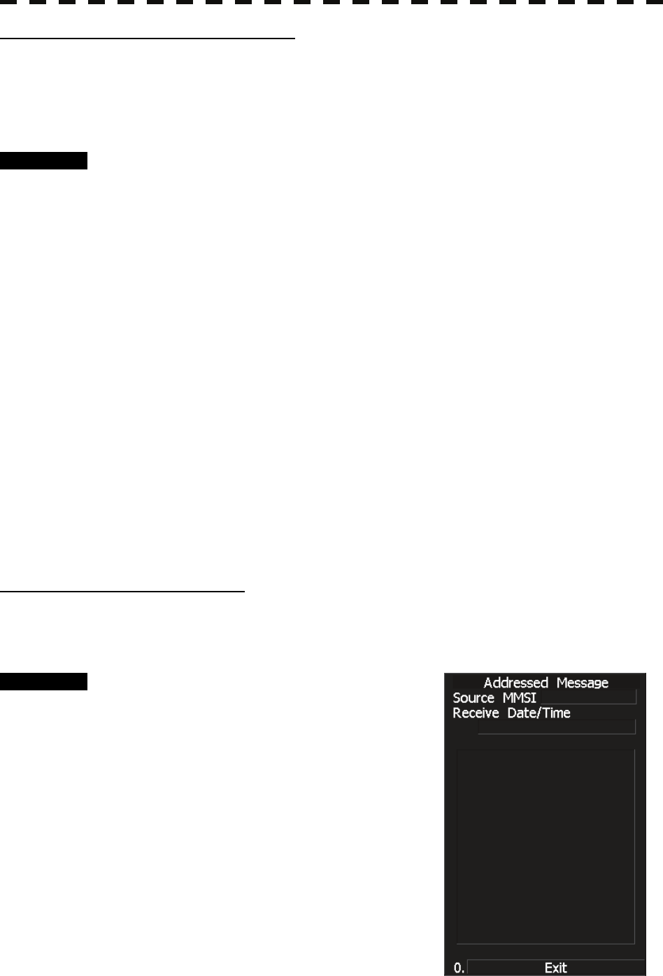
5─45
AIS information panel display setting
A set of AIS information to be preferentially displayed (before other sets of information) on the AIS
information panel can be specified.
Information type can be selected from the choices of: navigation information, ship information, and destination
and location information.
Procedure 1 Press the [TT menu] key.
2 Press the following buttons.
2. AIS setting
9. Next menu list
2. AIS numerical data display setting
Select AIS information panel display setting.
AIS numerical data display setting menu is displayed.
3 Press a number key for the desired setting.
Navigation information :
COG/SOG, CPA/TCPA, azimuth, distance, and turning ratio
Ship information :
ship name, call sign, and MMSI
Destination and location information :
destination, arrival time, and location
AIS information for the selected condition will be displayed.
Received AIS message display
Messages received from AIS can be displayed.
Messages can be displayed while the received AIS message display screen is displayed.
Procedure 1 Press the [TT menu] key.
2 Press the following buttons.
2. AIS setting
3. Received AIS message display
1. Messages for a specific address:
Messages sent to own ship are displayed.
2. Broadcasted message:
Messages sent to all vessels are displayed.
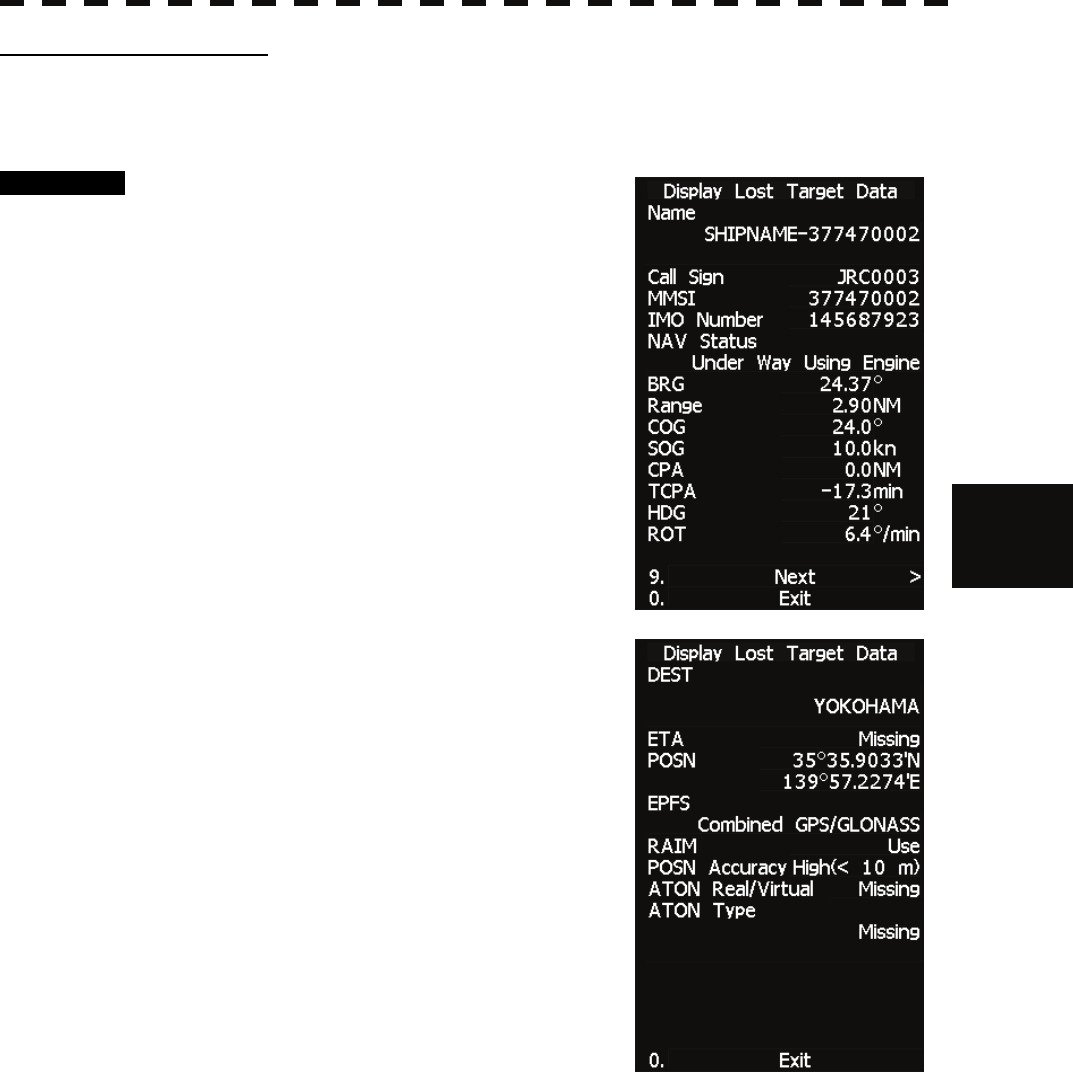
5.3 AIS OPERATION
5─46
5
yy
yyy
Lost target data display
Information of the last lost AIS target can be displayed.
Data can be displayed for the target that was lost most recently.
Procedure 1 Press the [TT menu] key.
2 Press the following buttons.
2. AIS setting
4. Lost target data display
Information of the last lost AIS target is
displayed.
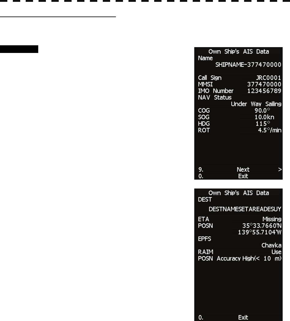
5─47
AIS own ship information display
AIS information for own ship can be displayed.
Procedure 1 Press the [TT menu] key.
2 Press the following buttons.
2. AIS setting
5. AIS own ship information display
AIS information for own ship is displayed.
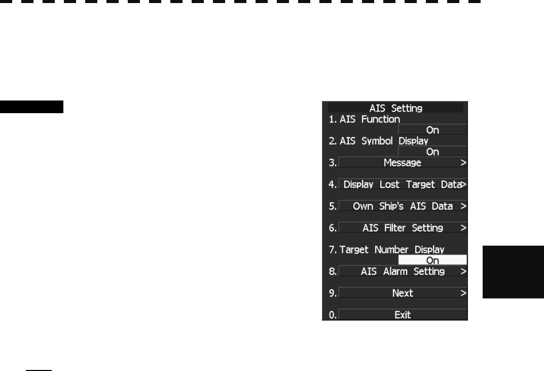
5.3 AIS OPERATION
5─48
5
yy
yyy
5.3.7 Displaying Target ID No. (Target Number Display)
A target ID number is a value displayed beside the AIS symbol.
ID numbers are assigned to AIS symbols in displayed order. ID numbers 1 to 130 are automatically assigned.
Each target is identified by the assigned ID number until it is lost.
Procedure 1 Press [TT MENU] key.
2 Press [2] key.
The TT Setting menu will appear.
3 Press [7] key.
The Target Number Display is switched ON or
OFF.
ON: Displays target ID numbers.
OFF: Hides target ID numbers.
Target TRACK:
Displays target ID number with target
track.
If there are many AIS targets and their symbol
display is confusing, set Target Number Display
to OFF to view the radar display easily.
Note: An ID number is always displayed for only targets with which numeric data is displayed.
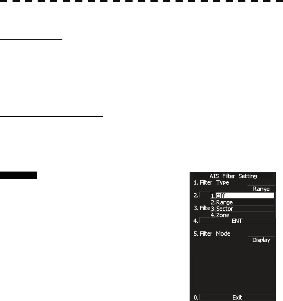
5─49
5.3.8 Setting AIS Filter (AIS Filter Setting)
About an AIS filter
Once the AIS filter is set, only the AIS targets that are inside the filter area are displayed (setting can be made
such that sleeping targets outside the AIS filter will not be shown).
The filter is initially set in a circle having a radius of 20 [nm] from the own ship’s position. If 131 or more
targets exist in the filter range, they are displayed according to the priority explained in “Types and Definitions
of AIS Target Symbols” of Section 5.1.2 “Definitions of Symbols.”
Type of AIS filters (Filter Type)
There are the following three types of AIS filters:
1) RANGE........ A filter is set in a circle with a set range as the radius.
2) SECTOR ...... A filter is set in a sector formed by two bearings with the bow as reference.
3) ZONE........... A filter is set in a zone formed by two bearings and two ranges with the bow as reference.
Procedure 1 Press [TT MENU] key.
Press [2] key.
Press [6] key.
The TT Filter Setting menu will appear.
2 Press [1] key.
The Filter type selection screen will appear.
3 Select the AIS filter type to be set,
pressing the numeric key.
The selected AIS filter type will be determined.
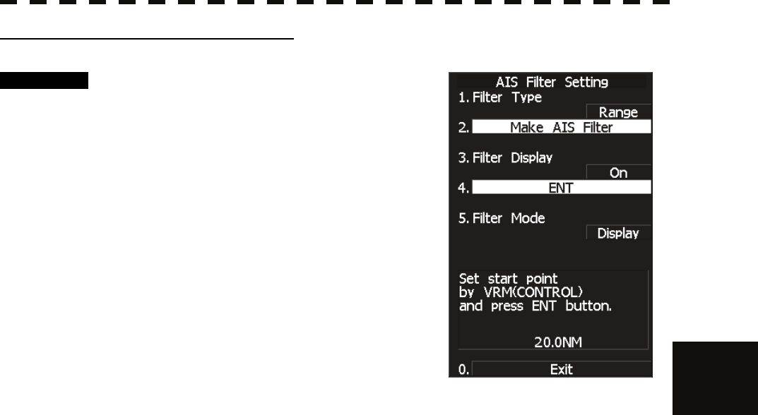
5.3 AIS OPERATION
5─50
5
yy
yyy
Making an AIS filter (Make AIS Filter)
Procedure 1 Press [2] key while the AIS Filter Setting
menu is open.
The Make AIS Filter screen will appear.
[I] Setting a RANGE filter
2 Turn the [VRM] key control to set a filter
range, and press [ENT] key.
The range of a RANGE filter will be set.
AIS targets in the set circle are displayed by
priority.
[II] Setting a SECTOR filter
2 Turn the [EBL] key control to set the
bearing of the port side, and press [ENT] key.
3 Turn the [EBL] key control to set the bearing of the starboard, and press
[ENT] key.
A SECTOR filter will be set.
AIS targets in the area formed by the two set bearings are displayed by priority.
[III] Setting a ZONE filter
2 Turn the [EBL] key and [VRM] key controls to set the bearing and range
of the port side, and press [ENT] key.
3 Turn the [EBL] key and [VRM] key controls to set the bearing and range
of the starboard, and press [ENT] key.
A ZONE filter will be set.
AIS targets in the area formed by the two set bearings and ranges are displayed by priority.
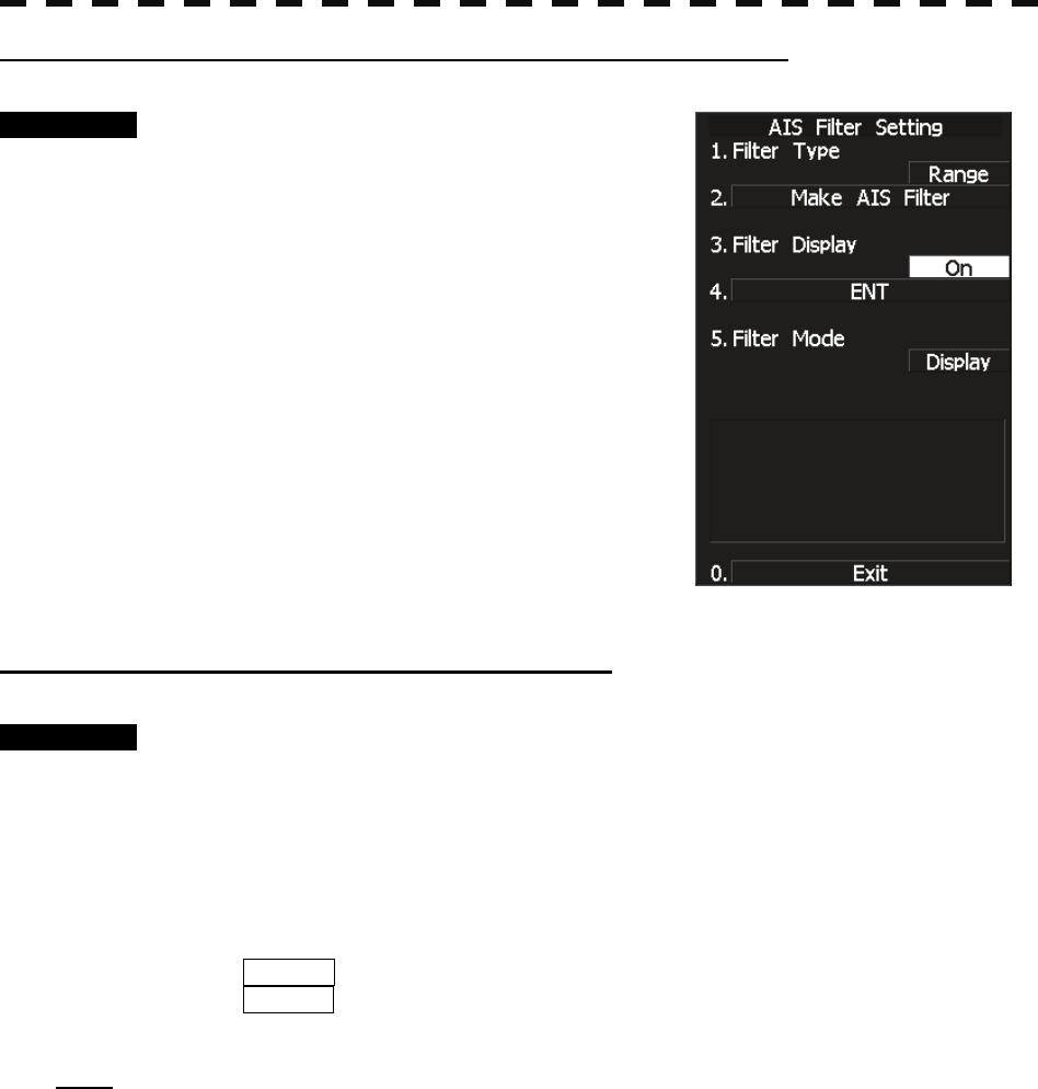
5─51
Setting the AIS filter display function to ON/OFF (Filter Display)
Procedure 1 Press [3] key while the AIS Filter Setting
menu is open.
The setting of AIS Filter display will be switched
ON or OFF.
ON: Displays the AIS filter.
OFF: Hides the AIS filter.
Display of Targets outside AIS Filter (Filter Mode)
Procedure 1 Press [TT MENU] key.
Press [2] key.
Press [6] key.
2 Press the [5] key.
The Filter Mode is switched.
Display :Displays only AIS targets in the AIS filter.
Priority :Displays AIS targets in the AIS filter by priority, and also displays targets
outside the AIS filter.
Note: Activated AIS targets can be displayed even when they are outside the AIS filter.
5.3 AIS OPERATION
5─52
5
yy
yyy
Point Filter
AIS targets which are not displayed because they are outside the AIS filter or at low priority levels can be
activated by giving a higher priority to them.
Procedure 1 Press a few times the CURSOR button at the top right corner of the
screen to call up ACT AIS .
The cursor mode is set to AIS activation mode.
2 Place the cursor over the location where you wish to set a point filter,
and press the [ENT] key.
A point filter will be set at the cursor position.
If an AIS target is in the point filter, it will be activated.
When an AIS target is activated or an AIS target is not found within ten seconds, the point
filter will be cleared.

5─53
5.3.9 Conditions for Deciding AIS Target to be Lost
About a lost target
When the data of an AIS target cannot be received for a specified time, the target is decided to be lost and the
target data is deleted. As shown in the table below, the time until target data is deleted varies depending on the
class of receive data and the target status.
Deciding AIS Target to be Lost
Time until data deletion
Target status SOLAS ship
(Class A)
SOLAS ship
(Class B)
Vessel below 3 knots and it is now at anchor or on the berth
(Class B: below 2 knots) 18 min 18 min
Vessel of 3 knots or more and it is now at anchor or on the berth 60 sec 18 min
Vessel of 0 to 14 knots (Class B: 2 to 14 knots) 60 sec 180 sec
Vessel of 0 to 14 knots and it is now changing the course 60 sec 180 sec
Vessel of 14 to 23 knots 36 sec 180 sec
Vessel of 14 to 23 knots and it is now changing the course 36 sec 180 sec
Vessel of 23 knots or more 30 sec 180 sec
Vessel of 23 knots or more and it is now changing the course 30 sec 180 sec
SAR (Search and Rescue) 60 sec 60 sec
ATON (Aid to Navigation) 18 min 18 min
Base station 60 sec 60 sec
Reference:
• If Active targets (including dangerous ships) and numerically displayed targets is lost, a lost target alarm is
issued, and the symbol changes to a lost target symbol. The system continues to display the symbol where it
received the last data. If the ALARM ACK switch is pressed, the symbol is cleared.

5.3 AIS OPERATION
5─54
5
yy
yyy
5.3.10 Setting AIS Alarm (AIS Alarm Setting)
Conditions for setting off a lost AIS target alarm (Lost) and a dangerous target alarm (CPA/TCPA) can be set.
Lost target alarm (Lost)
Procedure 1 Press the [TT menu] key.
Press [2] key.
Press [8] key.
2 Press the [2] key.
The Lost Alarm setting is switched.
Off : Lost target alarm will not be active.
Dangerous ship : Lost target alarm will sound only for the AIS targets for which a
dangerous target alarm has already been activated.
Activated and dangerous ship :
Lost target alarm will sound only for the AIS targets for which an
activated AIS target and dangerous target alarm has already been
activated.
Note: Sleeping AIS targets will not set off a lost target alarm.
Dangerous target alarm setting (CPA/TCPA)
Procedure 1 Press the [TT menu] key.
Press [2] key.
Press [8] key.
2 Press the [1] key.
The Target Alarm (CPA/TCPA) setting is switched.
Activated : Dangerous target alarm will be activated only for activated AIS
targets.
Activated & sleeping : Dangerous target alarm will be activated for all AIS targets that are
displayed.
Off : Dangerous target alarm will not be activated.
5─55
5.4 TARGET ASSOCIATION ASSESSMENT
(ASSOCIATION SETTING)
5.4.1 Target Association Assessment
Whether or not the AIS target and the tracked targets are identical is assessed. If they are determined to be
identical, an association symbol is displayed.
When this occurs, the AIS target symbol is activated automatically.
z Turn off the software button ⑪ Association
located at the other ship's information area in Section
2.3.6 if you wish to cancel association assessment or
to bring back symbols that are no longer displayed.
Atte
n
t
i
o
n
When a large value is set as an association
condition, a tracked target near an AIS target is
identified as the AIS target and may thus
disappear from the display.
For example, when a pilot vessel equipped with
the AIS function (a small target which is not a
tracked target) goes near a cargo vessel which
is a tracked target without the AIS function, the
tracked target symbol for the cargo vessel may
disappear.
Caution

5.4 TARGET ASSOCIATION ASSESSMENT (ASSOCIATION SETTING)
5─56
5
yy
yyy
Procedure 1 Press the [TT menu] key.
2 Press the following buttons.
3 Target setting
1 Association assessment setting
1 Association assessment
On : Use the association assessment function.
(Targets that are judged to be identical will be indicated as an association symbol.)
Off : Do not use the association assessment function.
(AIS target and tracked target are shown separately even though they are determined
to be identical.)
5.4.2 Priority
An association symbol can be created based on either AIS target data or tracked target data.
Procedure 1 Press the [TT menu] key.
2 Press the following buttons.
3 Target setting
1 Association assessment setting
2 Priority
AIS : Symbol is created and displayed based on AIS target data.
TT : Symbol is created and displayed based on tracked target data.
5.4.3 Azimuth
Set an azimuth difference between targets to be identified as one target.
Targets that are within the set azimuth range will be identified as one target.
Procedure 1 Press the [TT menu] key.
2 Press the following buttons.
3 Target setting
1 Association assessment setting
3 Azimuth
Set an azimuth difference between a tracked target and an AIS target to be identified as
one target. Set the azimuth range between 0.0 and 9.9 degrees.
A narrower azimuth range means a stricter condition.
The possibility of mistakenly identify resembling targets will be lower, but targets are less
likely to be identified as one target.
A wider azimuth range means a looser condition.
Targets are likely to be identified as one target, but targets with similar parameters are
likely to be mistakenly identified.
Adjust the setting in accordance with the intention.

5─57
5.4.4 Distance
Set a distance between targets to be identified as one target.
Targets that are within the set distance will be identified as one target.
Procedure 1 Press the [TT menu] key.
2 Press the following buttons.
3 Target setting
1 Association assessment setting
4 Distance
Set a distance between a tracked target and an AIS target to be identified as one target.
Set the distance between 0 and 999 m.
A shorter distance means a stricter condition.
The possibility of mistakenly identify resembling targets will be lower, but targets are less
likely to be identified as one target.
A longer distance means a looser condition.
Targets are likely to be identified as one target, but targets with similar parameters are
likely to be mistakenly identified.
Adjust the setting in accordance with the intention.
5.4.5 Course
Set a course difference between targets to be identified as one target.
Targets that are within the set course angle will be identified as one target.
Procedure 1 Press the [TT menu] key.
2 Press the following buttons.
3 Target setting
1 Association assessment setting
5 Course
Set a course difference between a tracked target and an AIS target to be identified as one
target. Set the course angle between 0 and 99 degrees.
A narrower course angle means a stricter condition.
The possibility of mistakenly identify resembling targets will be lower, but targets are less
likely to be identified as one target.
A wider course angle means a looser condition.
Targets are likely to be identified as one target, but targets with similar parameters are
likely to be mistakenly identified.
Adjust the setting in accordance with the intention.

5.4 TARGET ASSOCIATION ASSESSMENT (ASSOCIATION SETTING)
5─58
5
yy
yyy
5.4.6 Speed
Set a speed difference between targets to be identified as one target.
Targets that are within the set speed range will be identified as one target.
Procedure 1 Press the [TT menu] key.
2 Press the following buttons.
3 Target setting
1 Association assessment setting
6 Speed
Set a speed difference between a tracked target and an AIS target to be identified as one
target. Set the speed range between 0 and 99 kn.
A smaller speed range means a stricter condition.
The possibility of mistakenly identify resembling targets will be lower, but targets are less
likely to be identified as one target.
A larger speed range means a looser condition.
Targets are likely to be identified as one target, but targets with similar parameters are
likely to be mistakenly identified.
Adjust the setting in accordance with the intention.
5─59
5.4.7 Hysteresis
Set a hysteresis level at which a tracked target and an AIS target are identified as one target by the association
assessment function.
Set the condition for using an association symbol when a tracked target symbol and an AIS target symbol
overlap each other.
Procedure 1 Press the [TT menu] key.
2 Press the following buttons.
3 Target setting
1 Association assessment setting
7 Hysteresis
Set a level of hysteresis at which targets are identified as one target between 0% and 300%.
The standard percentage is 100%.
In the case of 100%, The level of hysteresis is equal to n/m.
n: The time of judgment which targets are identified as one target
m: The time of judgment
Therefore 50% means that the level of hysteresis is equal to n/(2*m).
200% means that the level of hysteresis is equal to (2*n)/m.
A larger value means a stricter condition.
The possibility of mistakenly identify resembling targets will be lower, but targets are less
likely to be identified as one target.
A smaller value means a looser condition.
Targets are likely to be identified as one target, but targets with similar parameters are
likely to be mistakenly identified.
Adjust the setting in accordance with the intention.
When a small value is set as a hysteresis
condition, a tracked target near an AIS target is
identified as the AIS target and may thus
disappear from the display.
For example, when a pilot vessel equipped with
the AIS function (a small target which is not a
tracked target) goes near a cargo vessel which
is a tracked target without the AIS function, the
tracked target symbol for the cargo vessel may
disappear.
Caution
5.4 TARGET ASSOCIATION ASSESSMENT (ASSOCIATION SETTING)
5─60
5
yy
yyy
5.4.8 Non-Hysteresis
Set a non-hysteresis level at which targets that were once identified as one target by the association assessment
function are identified as separate targets.
Set the condition for separating an association symbol into a tracked target symbol and an AIS target symbol.
Procedure 1 Press the [TT menu] key.
2 Press the following buttons.
3 Target setting
1 Association assessment setting
8 Non-Hysteresis
Set a level of non-hysteresis at which an associated target is separated into individual
targets between 0% and 300%. The standard percentage is 100%.
In the case of 100%, The level of non-hysteresis is equal to n/m.
n: The time of judgment which an associated target is separated into individual targets
m: The time of judgment
Therefore 50% means that the level of hysteresis is equal to n/(2*m).
200% means that the level of hysteresis is equal to (2*n)/m.
A larger value means a stricter condition.
It becomes harder to separate a tracked target symbol from an AIS target symbol.
Targets that are not separated to start with are less likely to be separated, and also,
separated individual symbols are less likely to be displayed properly after separation.
A smaller value means a looser condition.
It becomes easier to separate a tracked target symbol from an AIS target symbol.
Targets that are not separated to start with are more likely to be separated, and also,
separated individual symbols are more likely to be displayed soon after separation.
Adjust the setting in accordance with the intention.
When a small value is set as a hysteresis
condition, a tracked target near an AIS target is
identified as the AIS target and may thus
disappear from the display.
For example, when a pilot vessel equipped with
the AIS function (a small target which is not a
tracked target) goes near a cargo vessel which
is a tracked target without the AIS function, the
tracked target symbol for the cargo vessel may
disappear.
Caution

5─61
5.4.9 AIS Target to be Assessed
Specify an AIS target to be assessed for association.
Targets of association assessment can be either activated targets only or both activated and sleeping targets.
Procedure 1 Press the [TT menu] key.
2 Press the following buttons.
3 Target setting
1 Association assessment setting
9 AIS target to be assessed
Select AIS targets to be assessed for association.
Activated : Only activated targets will be assessed for association.
Activated & sleeping : All activated and sleeping targets will be assessed for association.

5.5 ALARM DISPLAY
5─62
5
yy
yyy
5.5 ALARM DISPLAY
Alarm messages for Target Tracking (TT) and AIS functions:
Error message Description
TT CPA/TCPA A dangerous target is detected in target tracking.
AIS CPA/TCPA A dangerous AIS target is detected.
TT(New Target) A new target being tracked was acquired in the automatic acquisition area.
AIS(New Target) A new AIS target was activated in the automatic acquisition area.
TT(Lost) A lost target is detected in target tracking.
AIS(Lost) A lost AIS target is detected.
REF TT(Lost) A reference TT target has been lost. (Accuracy decreased)
TT(MAX 95% Capacity) The number of TT targets acquired has reached 95% of the maximum acquisition
count.
TT(MAX Target) The number of TT targets acquired has exceeded the maximum acquisition count.
AIS(ACT 95% Capacity) The number of targets activated has reached 95% of the maximum activation
count.
AIS(ACT MAX) The number of targets activated has exceeded the maximum activation count.
AIS (MAX Target 95%) The number of AIS targets displayed has reached 95% of the maximum display
count.
AIS (MAX Target) The number of AIS targets displayed has exceeded the maximum display count.
TT processing unit
(Communication data
error) *
Communication error with the TT processing unit
AIS (No communication) No communication with AIS. The AIS transponder is not connected correctly or
the power is turned off.
AIS (Communication data
error)
AIS communication error. The data of communication with the AIS unit
contains an error.
AIS I/F (No
communication)
No communication with AIS IF. The AIS unit is not connected or is not
operating.
AIS I/F (No data
communication)
AIS I/F communication error. The data of communication with the AIS unit
contains an error.
AIS(Alarm ***) Alarm information issued with the ALR sentence by the AIS
*** is a 3-digit number which is Local Alarm No in the ALR sentence.
AIS Alarm 001 Tx malfunction
AIS Alarm 002 Antenna VSWR exceeds limit
AIS Alarm 003 Rx channel 1 malfunction
AIS Alarm 004 Rx channel 2 malfunction
AIS Alarm 005 Rx channel 70 malfunction
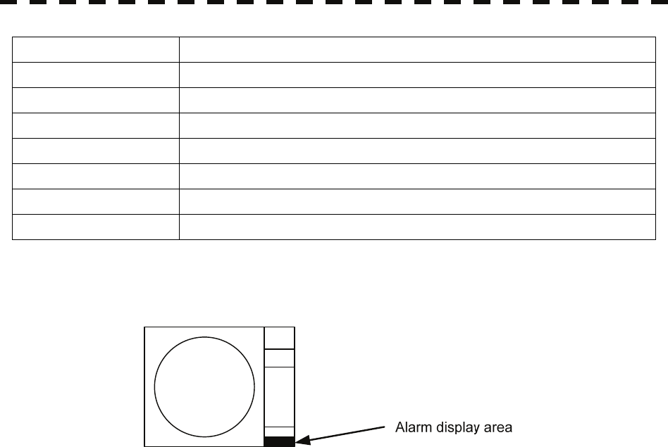
5─63
AIS Alarm 006 general failure
AIS Alarm 008 MKD connection lost
AIS Alarm 025 external EPFS lost
AIS Alarm 026 no sensor position in use
AIS Alarm 029 no valid SOG information
AIS Alarm 030 no valid COG information
AIS Alarm 032 Heading lost/invalid
AIS Alarm 035 no valid ROT information
An alarm is displayed in the alarm indication (software button ⑭ located at the operation/message area in
Section 2.3.9).
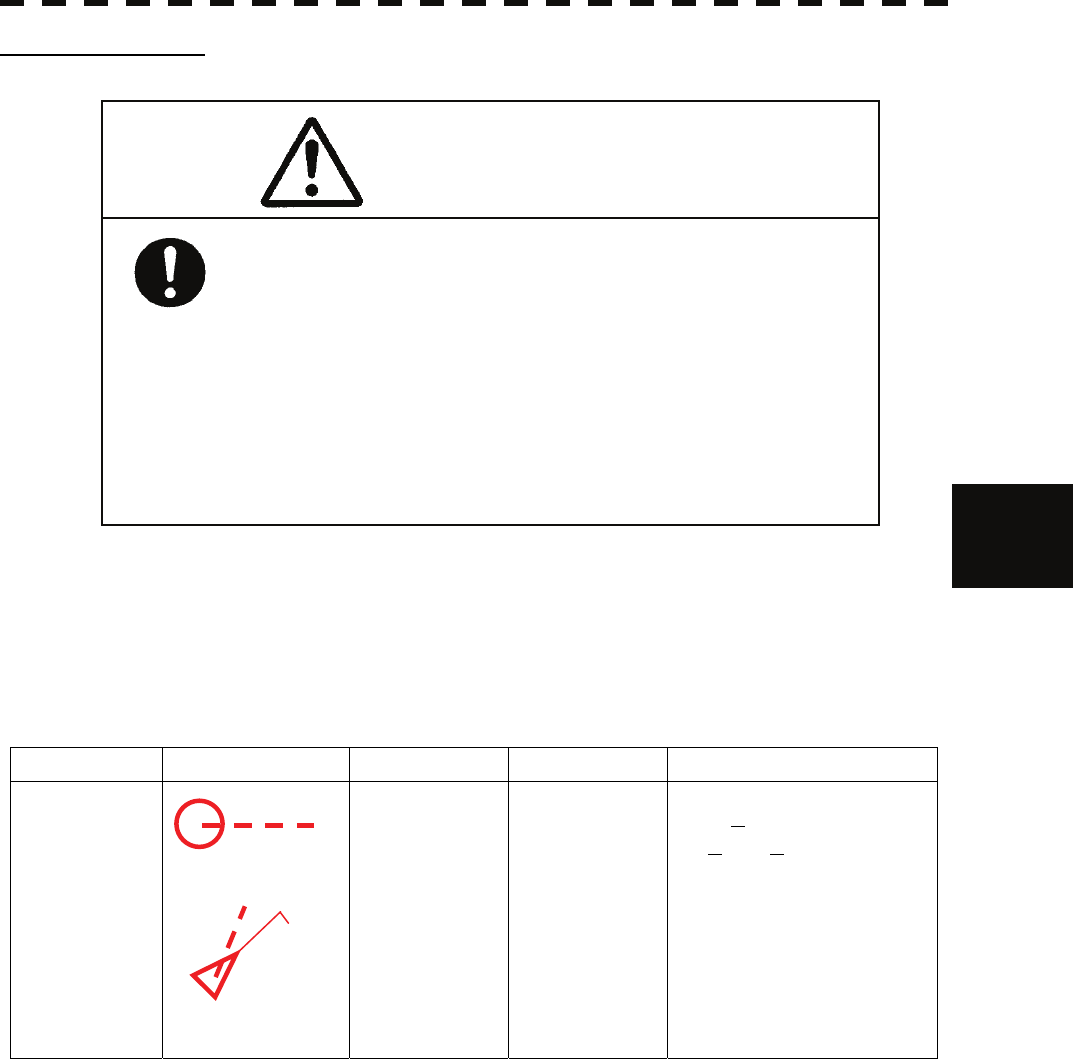
5.5 ALARM DISPLAY
5─64
5
yy
yyy
CPA / TCPA Alarm
In the system, targets are categorized into two types: tracked / activate AIS targets and dangerous targets.
The grade of danger can easily be recognized on the display at a glance. So the officer can easily decide which
target he should pay attention to.
The types of target and alarm are shown below.
CPA / TCPA Alarm
Status Symbol on display Alarm characters Alarm sound Conditions
Dangerous target
Red blinking
CPA / TCPA
Beep sound
(pee-poh)
Alarm
acknowledgeable
• CPA ≤ CPA LIMIT,
• 0 ≤ TCPA ≤ TCPA LIMIT
An alarm is issued when all the
conditions are met.
The AIS targets that issues
alarm refer to Section 5.1.5
“Setting Collision Decision
Criteria (CPA/TCPA Limit)”.
CPA Limit and TCPA Limit: The Setting Values
12
AIS12
Since these alarms may include some errors
depending on the target tracking conditions, the
navigation officer himself should make the final
decision for ship operations such as collision
avoidance.
Making the final navigation decision based only
on the alarm may cause accidents such as
collisions.
Caution
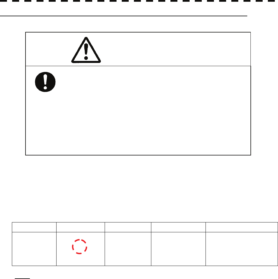
5─65
Alarm for New Target Acquired in Automatic Acquisition Zone (New Target)
The automatic acquisition function sets a zone in a range and issues an alarm when a new target (which is not
yet acquired) goes into this zone.
For the setting of an automatic acquisition zone, refer to “Automatic Acquisition [AUTO]” in Section 5.2.1
“Acquiring Target [ACQ].”
Alarm for New Target Acquired in Automatic Acquisition Zone
Status Symbol on display Alarm characters Alarm sound Conditions
New target in
automatic
acquisition zone
Red Blinking
New Target
Beep sound (pipi-pipi)
Alarm
acknowledgeable
The alarm is issued when a
new target is acquired in the
automatic acquisition zone.
Note: When an already acquired target goes into automatic acquisition zone, the alarm message is
not displayed and the buzzer does not sound either.
12
In setting an automatic acquisition zone, it is
necessary to adjust the gain, sea clutter
suppression and rain / snow clutter
suppression to ensure that target echoes are
displayed in the optimum conditions. No
automatic acquisition zone alarms will be
issued for targets undetected by the radar, and
this may cause accidents such as collisions.
Caution
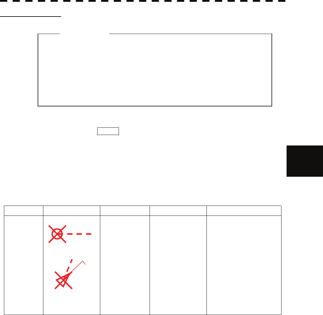
5.5 ALARM DISPLAY
5─66
5
yy
yyy
Lost Target Alarm
When it is impossible to continue tracking any acquired and tracked target, or the data of AIS target cannot
received for a specified time, the LOST alarm will be generated. The typical causes for alarm generation are
shown below, but not limited to the following:
• The target echo is very weak.
• The target is shadowed by a shore or a large ship and its echo is not received.
• The target echo is blurred by sea clutter returns.
If a target under tracking goes into a range of 32 nm and can no longer be tracked, it is canceled without a lost
target alarm being issued.
Lost Target Alarm
Status Symbol on display Alarm characters Alarm sound Conditions
Lost target
Red Blinking
Lost
Beep sound (pee)
Alarm
acknowledgeable
The alarm will sound once
when a lost target symbol is
displayed.
The AIS symbol blinks for x only.
12
AIS12
z If the gain, sea clutter suppression, rain/snow clutter
suppression are not adjusted adequately, the lost
target alarm may be easily generated. So such
adjustments should be mad carefully.
Attention
5─67
System Function Alarm (TT Data)
When an abnormal state of an input signal or Target Tracking unit may have a trouble, alarm is generated.
When an alarm occurs against any Target Tracking function, TT (Data) will appear in the alarm indication
(Software button ⑭ located at the operation/message area in Section 2.3.9), but no indication is made in the
Tracked Target information display (panel display area in Section 2.3.8). This status means that there is any
operational trouble in the Target Tracking unit. Please, contact the service depot or the manufactures.
System Function Alarm
Alarm characters Alarm sound Conditions
TT (DATA)
Beep sound (pipipi)
Alarm
acknowledgeable
An alarm sound is generated when a Target Tracking
circuit error occurs.
Gyro Set Alarm
The GYRO I/F in this system receives signals from a gyro. Even if the power is turned off, the system will
follow up the gyro. However, the system stops the follow-up operation when the power of the master gyro is
turned off or when any trouble occurs to the line. When the power of the master gyro is recovered, the
Set Gyro alarm will be generated.
If this alarm occurs, set the gyro.
Gyro Set Alarm
Alarm characters Alarm sound Conditions
Set Gyro Beep sound (pipi-pipi) The signals from the gyro are stopped, but the gyro is
recovered.
AIS Alarm Display
The following provides a list of the AIS alarm.
Alarm No. Definition
001 Tx malfunction
002 Antenna VSWR exceeds limit
003 Rx channel 1 malfunction
004 Rx channel 2 malfunction
005 Rx channel 70 malfunction
006 general failure
008 MKD connection lost
025 external EPFS lost
026 no sensor position in use
029 no valid SOG information
030 no valid COG information
032 Heading lost/invalid
035 no valid ROT information

5.6 TRACK DISPLAY
5─68
5
yy
yyy
5.6 TRACK DISPLAY
5.6.1 Display Past Tracks (Past Position)
With the past position function (Past Position), up to 6 past tracked and AIS target positions can be displayed (5
set time and distance intervals).
Select one of the time intervals at which past time positions should be displayed: 0.5 minutes, 1 minute, 2
minutes, and 4 minutes. Also, select one of the distance intervals at which past locations should be displayed:
0.1 NM, 0.2 NM, 0.5 NM, and 1 NM.
Procedure 1 Press the [TT menu] key.
2 Press the following buttons.
3 Target setting
3 Past position
3 Press a number key for the desired setting.
0.5 minutes, 1 minute, 2 minutes, and 4 minutes :
Past positions are displayed at a specified time interval.
0.1 NM, 0.2 NM, 0.5 NM, and 1 NM :
Past locations are displayed at a specified distance interval.
The selected interval will be displayed on the Past position display interval switching
button (Software button ⑥ located at the other ship's information area in Section 2.3.6).
The track display mode is not active when the button shows "Off." Track modes are
linked with vector modes to show a true or relative track. In relative vector mode, the
relative past position of the target is displayed. In true vector mode, the true past position,
which is calculated from the relative bearing/range and the own ship's course/speed, is
displayed.
The past position of a target being tracked is stored from when the target is acquired.
The past position of an AIS target is stored from when the target is activated.
If the past position plotted time is short, the indicated past position duration may not have
achieved the specified time or range.

5─69
5.6.2 Other Ship's Tracks (Target Track Setting)
Make track settings for acquired tracked and AIS targets.
This equipment can display tracks of up to 20 other vessels.
The target track function is available between latitudes of 85°N and 85°S.
* Tracks of other ships will not be recorded with the Target Track Function is deactivated.
[I] Track color setting (Target Track Color)
Procedure 1 Turn OFF the cursor mode.
2 Place the cursor over a tracked target or an AIS target, and press the
[CLR/INFO] key.
3 Target information menu opens.
4 Press the [2] key.
Track color choices are listed (Track Color).
5 Press a number key for the desired color.
The track will be shown in the selected color.
[II] Turning on/off the Target Track Function
Procedure 1 Press the [TT menu] key.
2 Press the following buttons.
4 Target Track Setting
1 Target Track Color
On : Activate the Target Track Function.
Off : Deactivate the Target Track Function.
* Selecting "Off" deactivates the entire Target Track Function.
Tracks will not be recorded; therefore, they cannot be checked later on.
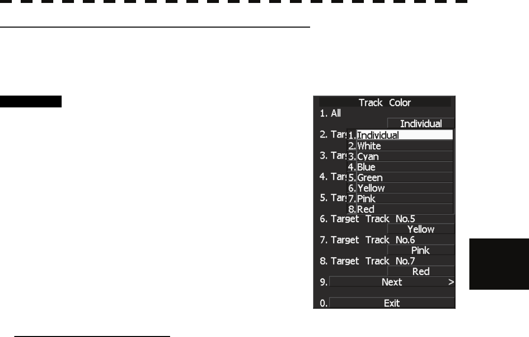
5.6 TRACK DISPLAY
5─70
5
yy
yyy
[III] Other ship's track color setting (Target Track Color)
The track color can be the same for all tracked targets, or different colors can be assigned to the first 20 targets.
* Tracks of other ships will not be recorded with the Target Track Function is deactivated.
Procedure 1 Press the [TT menu] key.
2 Press the following buttons.
4 Target Track Setting
2 Target Track Color
3 Press the [1] key.
Choices for "All" are displayed.
4 Press a number key for the desired
setting.
Individual : Assign different colors to individual
tracks.
Color name : The selected color will be assigned
to all tracks. Select a track color.
When "INDIVIDUAL" is selected
5 Press a number key for the desired track number.
Color choices for the selected track number are displayed.
6 Press a number key that corresponds to the desired track color.
The selected color will be assigned to the selected track.
Selecting "Individual" allows assignment of different colors to the first 20 tracks, from Track No.1 to Track
No.20. Select a color for each target. Press the target number to see the list of available colors. Then,
select a color.
There are 8 colors: Off/White/Cyan/Blue/Green/Yellow/Pink/Red.
* Note that different colors can be assigned to individual tracks only when "Individual" is selected.
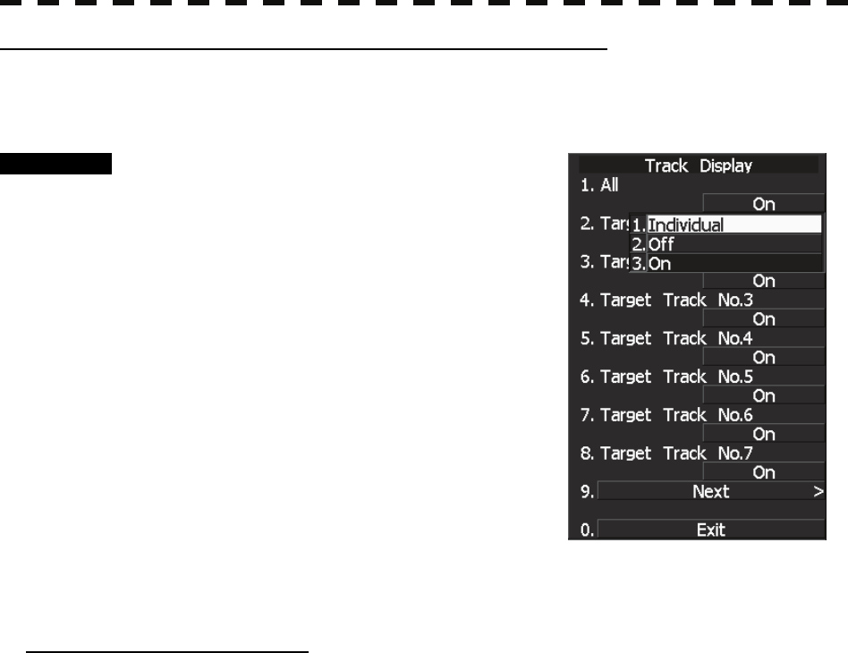
5─71
[IV] Other ship's track display setting (Target Track Display)
Other ship's track display can be turned on/off. Also, track display mode can be chosen between
display/non-display of all tracks and individual tracks.
Procedure 1 Press the [TT menu] key.
2 Press the following buttons.
4 Target Track Setting
3 Target Track Display
3 Press the [1] key.
Choices for "All" are displayed.
4 Press a number key for the desired
setting.
Individual : Set track display mode for each
track.
Off : Hide all tracks for all ships.
On : Show all tracks for all ships.
* Even though the track display mode is set to "Off," tracks of other ships are still
recorded as long as the track recording interval is set.
When "INDIVIDUAL" is selected
5 Press a number key for the desired track number.
Display/Non-display of the selected track can be set.
On : Show the track.
Off : Do not show the track.
Selecting "Individual" allows the track display mode to be set for the first 20 tracks, from Track No.1 to Track
No.20. For each target, decide whether or not the track should be displayed. The mode changes between On
and Off every time the On/Off window is pressed.
* Note that the track display mode can be set for individual tracks only when "Individual" is selected.
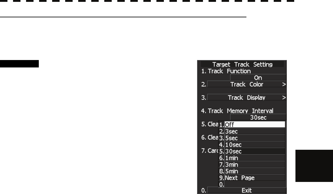
5.6 TRACK DISPLAY
5─72
5
yy
yyy
[V] Other ship track recording interval setting (Track Memory Interval)
A time interval for recording tracks of other ships can be set.
* This function can be used only when the Target Track Setting function is enabled.
Procedure 1 Press the [TT menu] key.
2 Press the following buttons.
4 Target Track Setting
4 Track Memory Interval
Choices for "Target Memory Interval" are
displayed.
3 Press a number key that corresponds
to the desired track recording interval.
Select from the following:
Off,
3 sec, 5 sec, 10 sec, 30 sec,
1 min, 3 min, 5 min, 10 min, 30 min, 60 min,
1 NM, 3 NM, 5 NM, and 10 NM
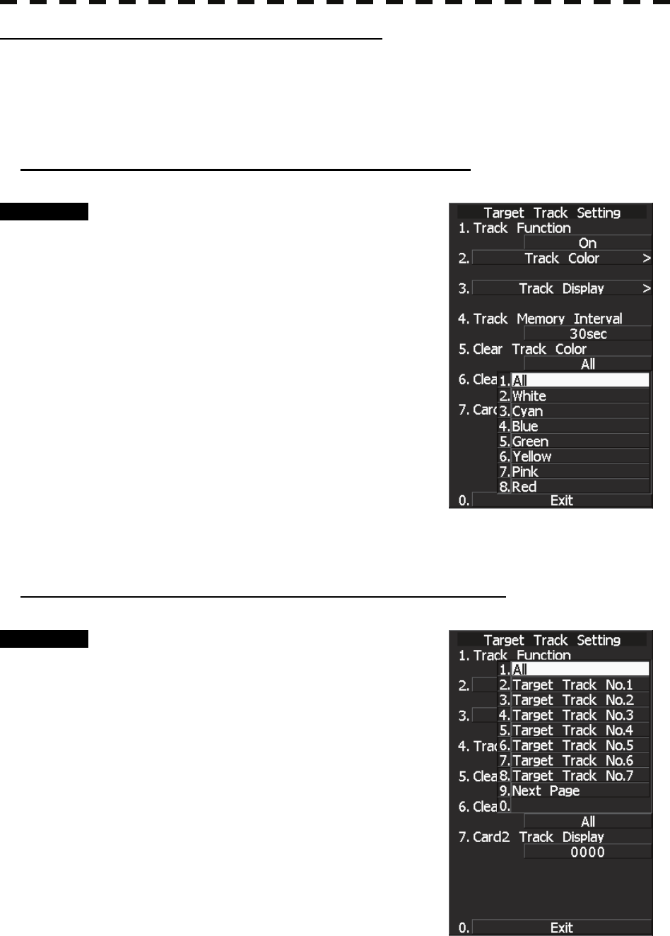
5─73
[VI] Deletion of other ship's tracks (Clear Track)
Tracks of other ships can be deleted. They can be deleted by track color or by track number.
* When using the card-based track display function (Card T. TRK Display), tracks of other ships that are
loaded from the card cannot be deleted.
Deletion of other ship's tracks by track color (Clear Track Color)
Procedure 1 Press the [TT menu] key.
2 Press the following buttons.
4 Target Track Setting
5 Clear Track Color
Choices for "Clear Track Color" are displayed.
3 Press a number key that corresponds
to the track color to be deleted.
The confirmation dialog window opens.
4 Press the [1] key.
Tracks of the selected color will all be deleted.
Select ALL to delete all tracks regardless of the
color.
Deletion of other ship's tracks by track number (Clear Track Number)
Procedure 1 Press the [TT menu] key.
2 Press the following buttons.
4 Target Track Setting
6 Clear Track Number
Choices for "Clear Track Number" are displayed.
3 Press a number key that corresponds
to the track number to be deleted.
The confirmation dialog window opens.
4 Press the [1] key.
Tracks of the selected number will all be deleted.
Select ALL to delete all tracks regardless of the
number.
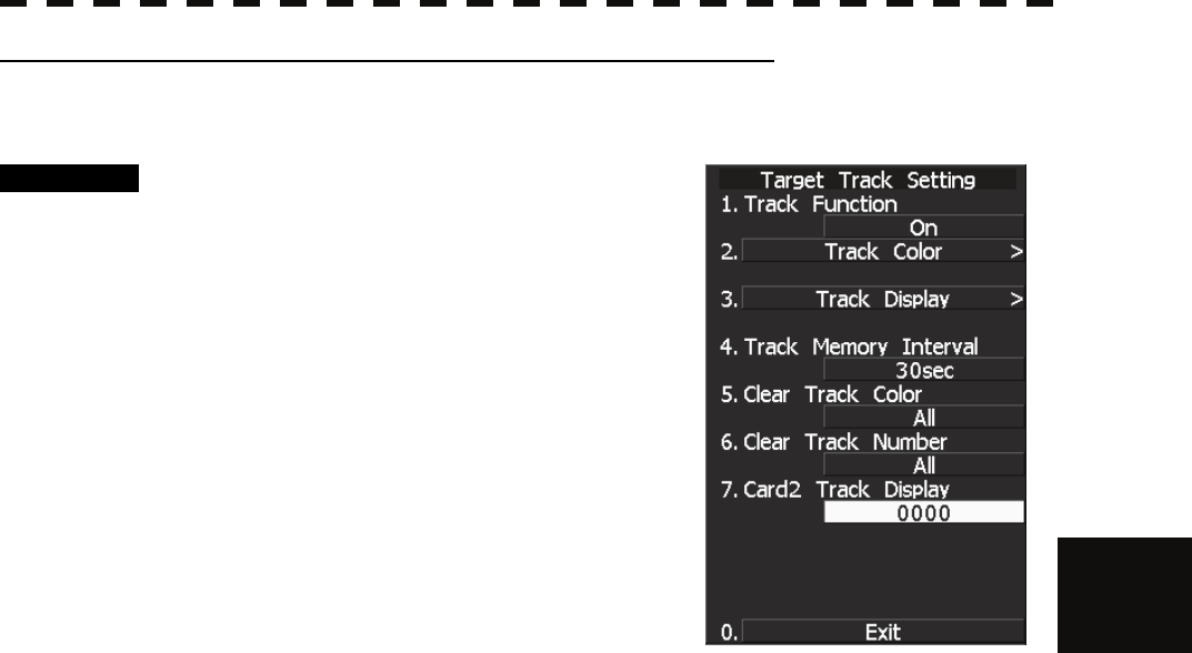
5.6 TRACK DISPLAY
5─74
5
yy
yyy
[VII] Loading target tracks from CARD2 (Card2 Track Display)
Target tracks saved in CARD2 can be loaded.
Procedure 1 Insert a Flash memory card into the
card slot.
Refer to the attached instruction manual for how
to insert/remove the card.
2 Press the [TT menu] key.
3 Press the following buttons.
4 Target Track Setting
7 Card2 Track Display
4 Input the number of track and press the
[ENT] key.
Data of the selected track number is loaded and
displayed on the radar screen.

5─75

SECTION 6
TRUE AND FALSE ECHOES
ON DISPLAY
6.1 RADAR WAVE WITH THE HORIZON................................. 6-2
6.2 STRENGTH OF REFLECTION FROM THE TARGET........ 6-4
6.3 SEA CLUTTER AND RAIN AND SNOW CLUTTER........... 6-6
6.4 FALSE ECHOES ............................................................... 6-10
6.5 DISPLAY OF RADAR TRANSPONDER (SART).............. 6-13

6─1
The radar operator has a role of interpreting the radar displays to provide his best aid in maneuvering the ship.
For this purpose, the operator has to observe the radar displays after fully understanding the advantages and
disadvantages that the radar has. For better interpretation of radar display, it is important to gain more
experiences by operating the radar equipment in fair weathers and comparing the target ships watched with the
naked eyes and their echoes on the radar display.
The radar is mainly used to monitor the courses of own ship and other ships in open seas, to check buoys and
other nautical marks when entering a port, to measure own ship’s position in the coastal waters relative to the
bearings and ranges of the shore or islands using a chart, and to monitor the position and movement of a heavy
rain if it appears on the radar display.
Various types of radar display will be explained below.
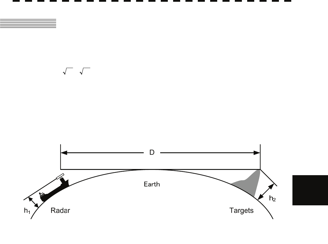
6.1 RADAR WAVE WITH THE HORIZON
6─2
6
yyy
yyy
6.1 RADAR WAVE WITH THE HORIZON
Radar beam radiation has the nature of propagating nearly along the curved surface of the earth.
The propagation varies with the property of the air layer through which the radar beam propagates.
In the normal propagation, the distance (D) of the radar wave to the horizon is approximately 10% longer than
the distance to the optical horizon. The distance (D) is given by the following formula:
D=2.23( h2h1 +)(nm)
h1: Height (m) of radar scanner above sea level
h2: Height (m) of a target above sea level
Figure 6.1 is a diagram for determining the maximum detection range of a target that is limited by the curve of
the earth surface in the normal propagation.
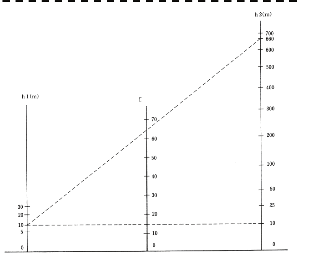
6─3
Figure 6.1
When the height of own ship’s scanner is 10 m for instance,
(a) A target that can be detected at the radar range of 64 nm on the radar display is required to have a height
of 660 m or more.
(b) If the height of a target is 10 m, the radar range has to be approx. 15 nm. However, the maximum
radar range at which a target can be detected on the radar display depends upon the size of the target
and the weather conditions, that is, the radar range may increase or decrease depending upon those
conditions.
Height of Radar Scanner Detective Range Height of Target
D (nm)
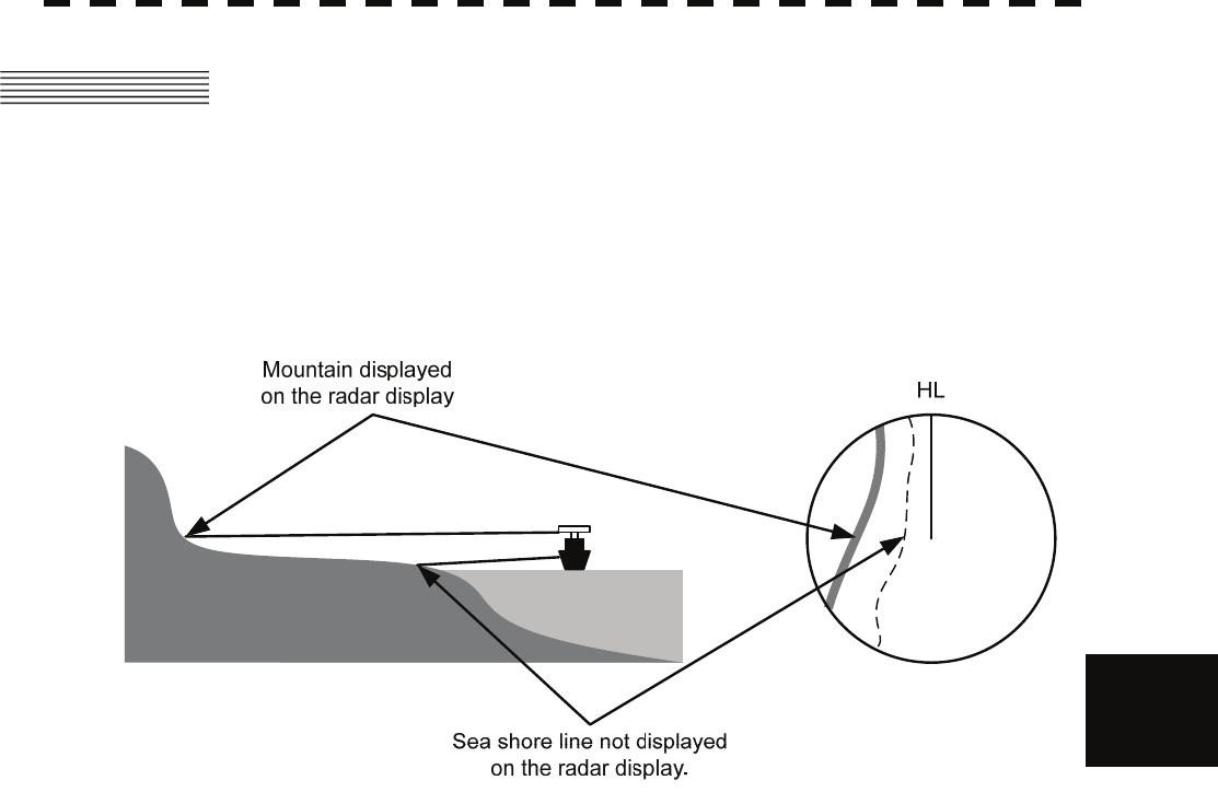
6.2 STRENGTH OF REFLECTION FROM THE TARGET
6─4
6
yyy
yyy
6.2 STRENGTH OF REFLECTION FROM THE
TARGET
The signal intensity reflected from a target depends not only on the height and size of the target but also on its
material and shape. The echo intensity from a higher and larger target is not always higher in general.
In particular, the echo from a coast line is affected by the geographic conditions of the coast.
If the coast has a very gentle slop, the echo from a mountain of the inland appears on the radar display.
Therefore, the distance to the coast line should be measured carefully.
Figure 6.2
Table 6.1 shows the graph indicating the relation between the target detection distance and the radar reflection
cross-sectional area (RCS) with regard to the type and the height of the target in a situation in which the
weather is good, the sea state is calm and the radio wave propagation is normal. As revealed by this table, even
on the same sea shore line, detection distance greatly differs depending on the height of the target from the
surface of the sea. Furthermore, because the target detection distance is greatly influenced by the shape and
material of the target and environmental conditions, such as the sea state, weather, and radio wave propagation,
caution should be taken when detecting distance of target.
6─5
Table 6.1 Relation between type and height of target and detection distance and RCS
Caution: Detection distance shown in the above table may greatly decrease depending on the shape of the
target, sea state, weather and radio wave propagation conditions.
Detection distance (NM) RCS (m²)
Type of target
Height from
sea surface
(m) X band S band X band S band
Sea shore line 60 20 20 50,000 50,000
Sea shore line 6 8 8 5000 5000
Sea shore line 3 6 6 2500 2500
SOLAS target ship (>5000GT) 10 11 11 50,000 30,000
SOLAS target ship (>500GT) 5 8 8 1800 1000
Small boat with IMO standard
compatible radar reflector 4 5.0 3.7 7.5 0.5
Marine buoy with corner reflector 3.5 4.9 3.6 10 1
Standard marine buoy 3.5 4.6 3.0 5 0.5
10-meter small boat without radar
reflector 2 3.4 3.0 2.5 1.4
Waterway location beacon 1 2.0 1.0 1 0.1
6.3 SEA CLUTTER AND RAIN AND SNOW CLUTTER
6─6
6
yyy
yyy
6.3 SEA CLUTTER AND RAIN AND SNOW
CLUTTER
In addition to the echo required for observing ships and land radar video image also includes unnecessary echo,
such as reflection from waves on the sea surface and reflection from rain and snow. Reflection from the sea
surface is called "sea clutter," and reflection from rain and snow is called "rain and snow clutter," and those
spurious waves must be eliminated by the clutter rejection function.
[I] Sea clutter
Sea clutter appears as an image radiating outwardly from the center of the radar display and changing
depending on the size and the shape of waves. Generally, as waves become larger, image level of the sea
clutter is intensified and the clutter far away is also displayed. When waves are large and the sea clutter
level is high, it is difficult to distinguish sea clutter from a small boat whose reflection intensity is weak.
Accordingly, it is necessary to properly adjust the sea clutter rejection function. Table 6.2 shows the
relation between the sea state (SS) showing the size of waves generated by wind and the radar's detection
probability.
Table 6.2 Sea state and probability of target detection
S band radar (probability to detect a target at a distance of 0.4 NM)
X band radar (probability to detect a target at a distance of 0.7 NM)
V: Detection probability of 80 %
M: Detection probability of 50 %
NV: Detection probability of less than 50 %
RCS SS1 to 2 SS2 to 3 SS3 to 4 SS4 to 5
0.1m2 V V-M M-NV
0.5 m2 V V V-M M-NV
1 m2 V V V V-M
RCS SS1 to 2 SS2 to 3 SS3 to 4 SS4 to 5
1m2 V-M M-NV
5 m2 V V-M M-NV
10 m2 V V V V-M
6─7
As shown in Table 6.3, the number of SS increases as the wind speed becomes high and the waves become
large. Table 6.2 reveals that detection probability decreases from V (80 %) to NV (less than 50 %) as the
number of SS increases. Therefore, even if the sea state is calm and a target clearly appears on the radar
display, when the sea state becomes rough, target detection probability decreases resulting in difficulty of
target detection by the radar.
Table 6.3 Relation between Douglas sea state and average wind speed and significant wave height
Significant wave height: an average of top N/3 higher waves when the number
of waves detected within a constant time duration is N
For example, in the case of a standard marine buoy, RCS of X band radar is 5 m2 as shown in Table 6.1.
When observing such a target in the sea state (SS3) in which significant wave height exceeds 1.2 meters,
detection probability is M-NV, as shown in Table 6.2, which indicates 50 % or less.
[II] Rain and snow clutter
Rain and snow clutter is a video image that appears in a location where rain or snow is falling. The image
changes according to the amount of rain (or the amount of snowfall). As precipitation increases, the image
of rain and snow clutter becomes intensified on the radar display, and in the case of localized heavy rain,
an image similar to the image indicating land is displayed in some cases. Furthermore, because radio
waves tend to attenuate due to rain and snow, the ability to detect a target in the rain and snow clutter or a
target beyond the rain and snow clutter may decrease. The amount of attenuation depends on the
transmission frequency, antenna beam width, and the pulse length. Figure 6.3 and Figure 6.4 show
examples in which detection distance is reduced due to the influence of precipitation. Because of this, a
target, which clearly appeared up to 10 NM by an X band radar (pulse width of 0.8 μs) when it was not
raining, may become dimly visible up to 5 NM when the amount of rain becomes 4 millimeters per hour.
Furthermore, when comparing the X band radar with the S band radar, target detection distance decreases
less when an S band radar is used, which means it is influenced less by precipitation.
Sea state Average wind speed (kn) Significant wave height (m)
0 <4 <0.2
1 5-7 0.6
2 7-11 0.9
3 12-16 1.2
4 17-19 2.0
5 20-25 3.0
6 26-33 4.0
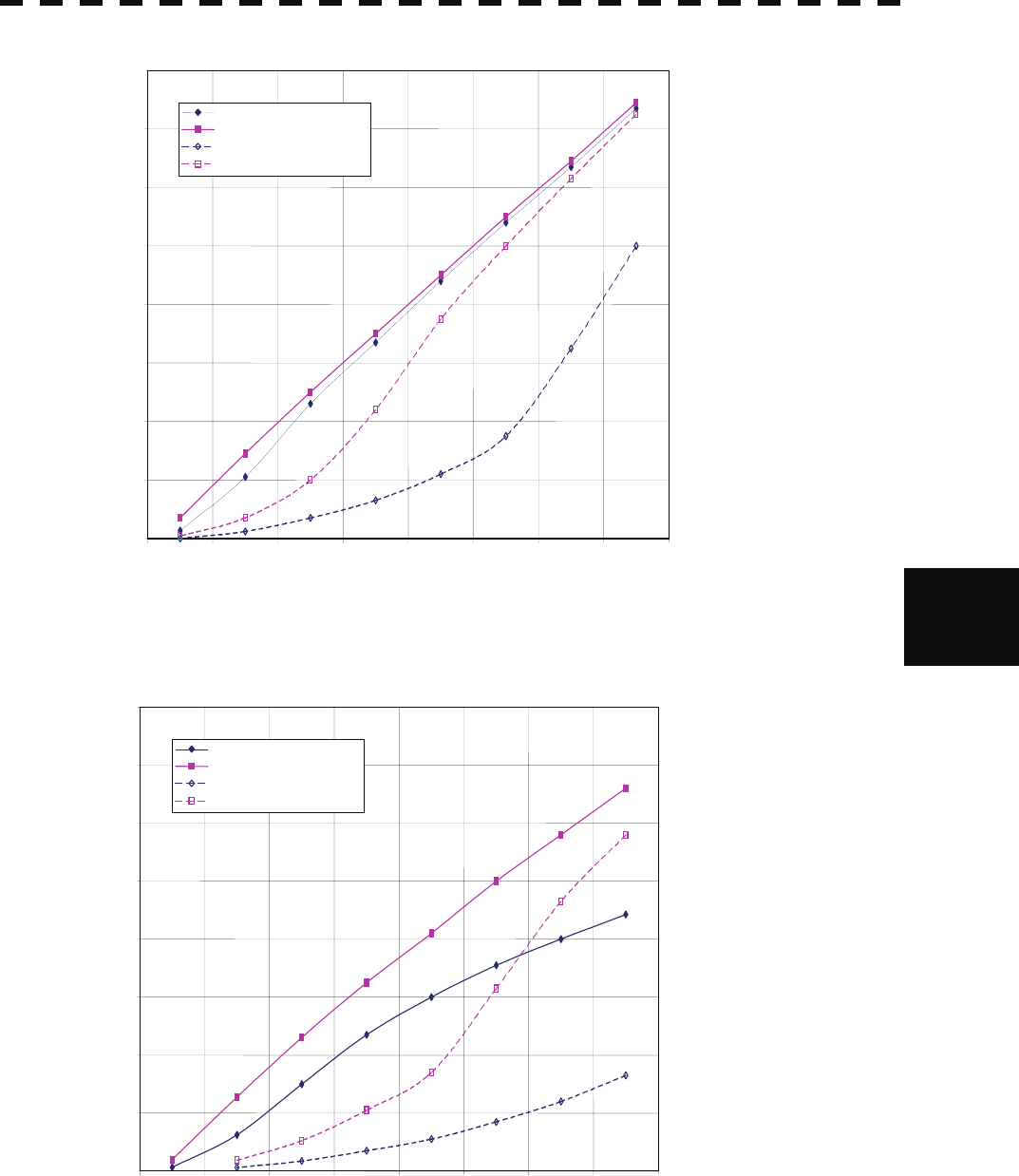
6.3 SEA CLUTTER AND RAIN AND SNOW CLUTTER
6─8
6
yyy
yyy
Figure 6.3 Decreased target detection distance by S band radar due to precipitation
Figure 6.4 Decreased target detection distance by X band radar due to precipitation
0
2
4
6
8
10
12
14
16
0 2 4 6 8 10 12 14 16
Detection distance while it is raining (NM)
Precipitation of 16 mm/hr Pulse width 0.05 μs
Precipitation of 4 mm/hr Pulse width 0.05 μs
Precipitation of 16 mm/hr Pulse width 0.8 μs
Precipitation of 4 mm/hr Pulse width 0.8 μs
Detection distance while it is not raining (NM)
0246 8 1 12 14 16
Detection distance while it is not raining (NM)
Precipitation of 16 mm/hr Pulse width 0.05 μs
Precipitation of 4 mm/hr Pulse width 0.05 μs
Precipitation of 16 mm/hr Pulse width 0.8 μs
Precipitation of 4 mm/hr Pulse width 0.8 μs
Detection distance while it is raining (NM)
0
2
4
6
8
10
12
14
16

6─9
[III] Coping with sea clutter and rain and snow clutter
When the weather is bad and the ocean is rough, the use of an S band radar is effective because the radar is
not influenced by sea clutter so much and attenuation due to rain drops is small. When an X band radar is
used, reducing the pulse width will reduce the influence by spurious waves, and also the spurious wave
rejection function effectively works; therefore, the use of short pulse is effective when the weather is bad.
By using image processing functions PROCl 1 to 3, it is expected that spurious waves are further
suppressed. Since optimal settings for those items can be automatically made by using the function mode,
it is recommended that STORM or RAIN be used by selecting the function mode when the weather is bad.
For details of the function mode, see Section 3.10 “USE FUNCTION SWITCH [FUNC]”.
However, these functions may make some targets invisible, particularly targets with higher speeds.
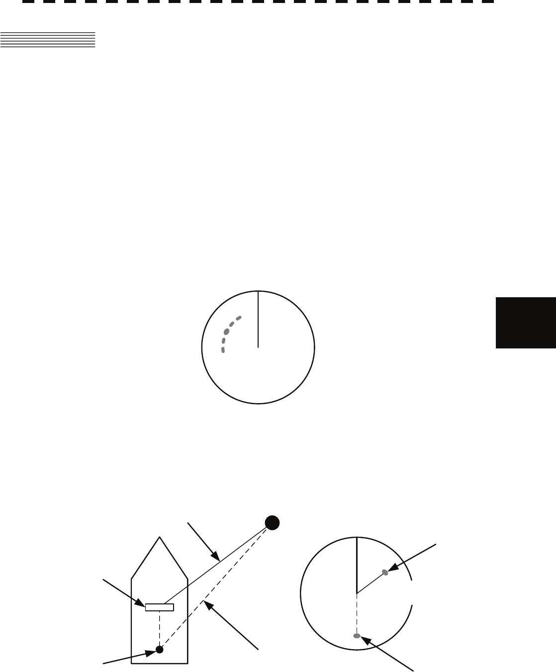
6.4 FALSE ECHOES
6─10
6
yyy
yyy
6.4 FALSE ECHOES
The radar observer may be embarrassed with some echoes that do not exist actually. These false echoes
appear by the following causes that are well known:
[I] Shadow
When the radar scanner is installed near a funnel or mast, the echo of a target that exists in the direction of
the funnel or mast cannot appear on the radar display because the radar beam is reflected on the funnel or
mast. Whether there are some false echoes due to shadows can be checked monitoring the sea clutter
returns, in which there may be a part of weak or no returns.
Such shadows appear always in the same directions, which the operator should have in mind in radar
operation.
[II] Side Lobe Effect
A broken-line circular arc may appear at the same range as the main lobe of the radar beam on the radar
display. This type of false echo can easily be discriminated when a target echo appears isolated. (See
Figure 6.5.)
HL
Figure 6.5
[III] False Echo by Secondary Reflection
When a target exists near own ship, two echoes from the single target may appear on the radar display.
One of those echoes is the direct echo return from the target and the other is the secondary reflection return
from a mast or funnel that stands in the same direction as shown in Figure 6.6.
Radar
scanner
Funnel
HL
Direct microwave
Secondary reflection
of microwave
Actual target
False echo from funnel
Figure 6.6
False echo from funnel
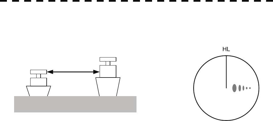
6─11
[IV] False Echo by Multiple Reflection
When there is a large structure or ship with a high vertical surface near own ship as shown in Figure 6.7,
multiple refection returns may appear on the radar display. These echoes appear in the same intervals, of
which the nearest echo is the true echo of the target.
Figure 6.7
[V] Second Time Echoes
The maximum radar detection range depends upon the height of the scanner and the height of a target as
described in the Section 6.1 “RADAR WAVE WITH THE HORIZON”. If a so-called "duct" occurs on
the sea surface due to a certain weather condition, however, the radar beam may propagate to a abnormally
long distance, at which a target may be detected by the radar.
For instance, assuming that the pulse length is MP3 (on the repetition frequency of 1400 Hz), the first
pulse is reflected from a target at about 58 NM or more and received during the next pulse repetition time.
In this case, a false echo (second time echo) appears at a position that is about 58 NM shorter than the
actual distance. If the false echo appears at 5 NM on the radar display, the true distance of the target is
5+58=63 NM. On the pulse length is SP1 (on the repetition frequency of 2250 Hz), a false echo may
appear at a position that is about 36 NM shorter than the actual distance.
This type of false echo can be discriminated by changing over the range scale (the repetition frequency),
because the distance of the target changes accordingly.
If second time echo is appeared, the use of Economy mode in PRF menu is effective. Otherwise, Stagger
Trigger menu set to on. (Refer to Section 3.9.5 “Set Scanner (TXRX Setting)”.)
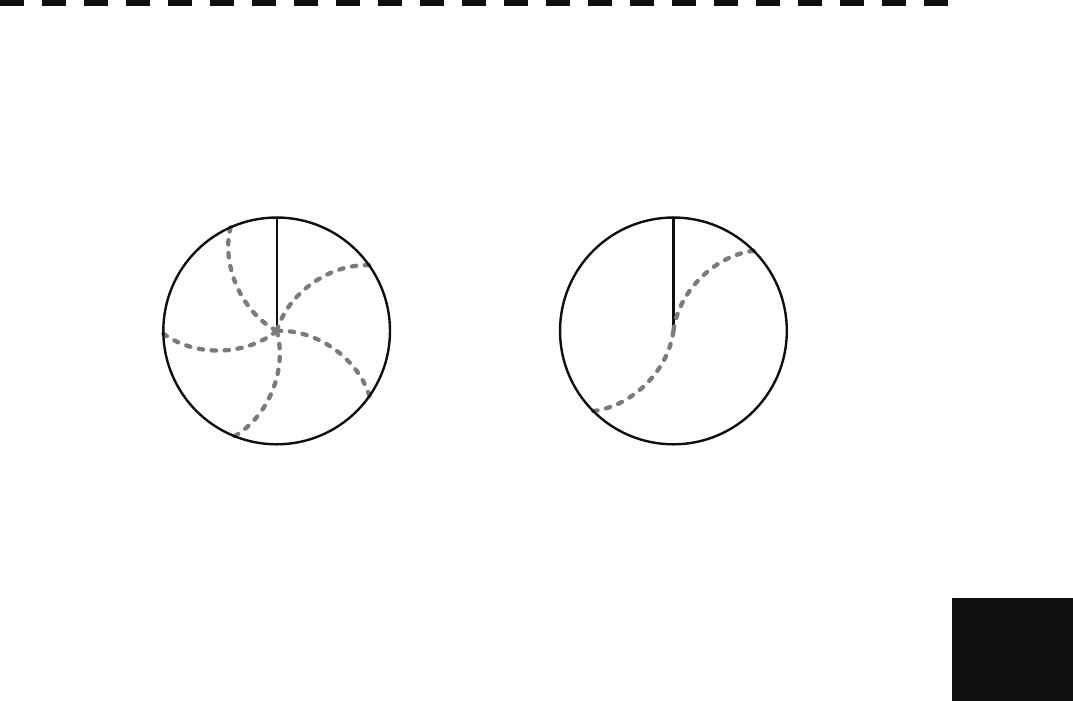
6.4 FALSE ECHOES
6─12
6
yyy
yyy
[VI] Radar Interference
When another radar equipment using the same frequency band as that on own ship is near own ship, a
radar interference pattern may appear on the radar display. This interference pattern consists of a number
of spots which appear in various forms. In many cases, these spots do not always appear at the same
places, so that they can be discriminated from the target echoes. (See Figure 6.8.)
HL HL
Figure 6.8
If radar equipment causing an interference pattern and this radar are of the same model, their transmitting
repetition frequency is nearly the same. As a result, interference patterns may be displayed
concentrically.
In this case, the interference patterns cannot be eliminated by using only the interference reflector function,
so press [TX/PRF] several times to fine-tune the transmitting repetition frequency.
An interference suppressing effect can be heightened by applying a different transmitting repetition
frequency to the interference pattern source radar and this radar.
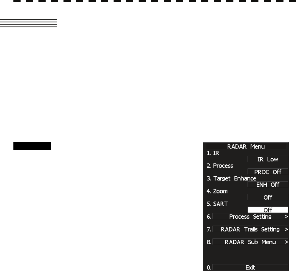
6─13
6.5 DISPLAY OF RADAR TRANSPONDER
(SART)
The SART (Search and rescue Radar Transponder) is a survival device authorized by the GMDSS (Global
Maritime Distress and Safety System), which is used for locating survivors in case that a distress accident
occurs at sea. The SART is designed to operate in the 9 GHz frequency band.
When receiving the 9 GHz radar signal (interrogating signal) transmitted from the radar equipment on a rescue
ship or search aircraft, the SART transmit a series of response signals to inform the distress position to the
rescue and search party.
* This radar provides a shortcut item to make settings for SART signal reception. Execution of this item
automatically switches to the setting for SART reception.
It also functions for detect the beacon or target enhancer.
Procedure 1 Press [RANGE +] or [RANGE -] to set
the radar range to 6 NM or 12 NM.
2 Press [RADAR MENU] twice.
The RADAR Menu will appear.
3 Press [5].
Each time the key is pressed, switching between
ON and OFF takes place.
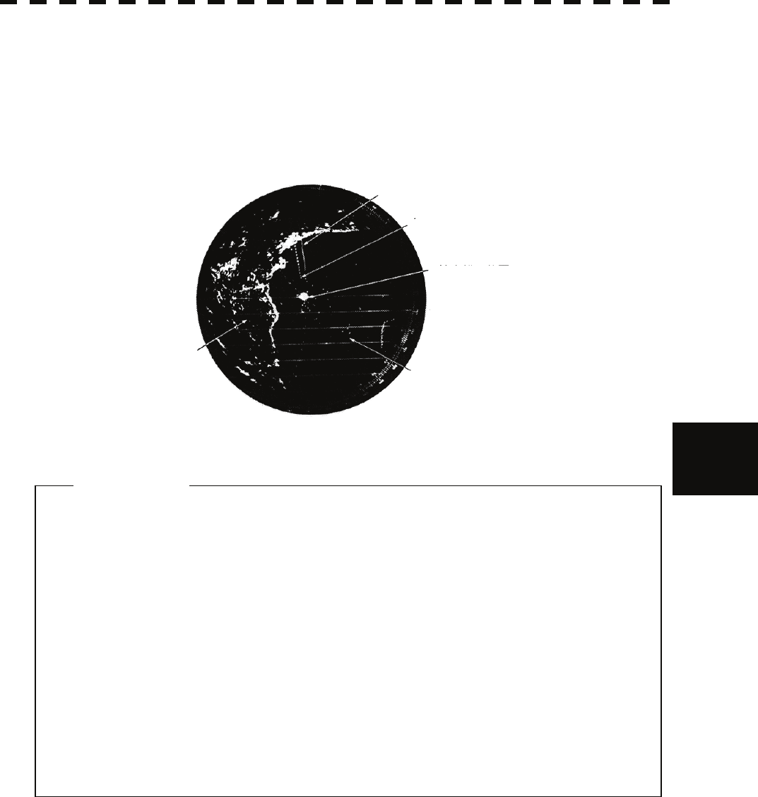
6.5 DISPLAY OF RADAR TRANSPONDER
6─14
6
yyy
yyy
With the SART display mode set to ON, settings as shown below are made automatically.
(1) Sea clutter control: Minimum (Most counterclockwise)
(2) AUTO SEA function: OFF
(3) Rain and Snow Clutter Control (RAIN): minimum
(4) Auto Rain and Snow Clutter function (AUTO RAIN): OFF
(5) TUNE control: No tuning (to weaken clutter echoes)
(6) Interference rejector (IR): OFF
(7) PROCESS: OFF
[Example of Display]
SART code
Position of SART
Position of the rescue craft
Other ships
Land
z When the SART function is set to ON, small targets around own ship will
disappear from the radar display. So it is necessary to exercise full
surveillance over the conditions around own ship by visual watch in
order to avoid any collision or stranding.
If two or more sets of radar equipment are installed on own ship, use
one set of 9 GHz band radar for detection of the SART signal and
operate others as normal radars for avoiding collision, monitoring
targets around own ship, and checking on own ship's position and
avoidance of stranding.
After end of detecting the START signal, turn the START display off.
Then the radar returns normally to the nautical mode.
Attention

6─15

SECTION 7
SETTINGS FOR SYSTEM OPERATION
7.1 SETTINGS AT INSTALLATION.................................... 7-1
7.1.1 How to open the Adjust Menu ............................. 7-2
7.1.2 Tuning Adjustment ............................................... 7-3
7.1.3 Bearing Adjustment ............................................. 7-6
7.1.4 Range Adjustment................................................ 7-7
7.1.5 Antenna Height Setting (Antenna Hight)............ 7-8
7.1.6 Setting of CCRP/Antenna/GPS Antenna Position
(CCRP Setting)...................................................... 7-9
7.2 NAVIGATOR SETTING ...............................................7-11
7.2.1 Ship Heading Equipment Setting
(Heading Equipment) ......................................... 7-14
7.2.2 NSK Unit Setting................................................. 7-15
7.2.3 True Bearing Value Setting (Set GYRO) ........... 7-17
7.2.4 MAG Compass Setting....................................... 7-18
7.2.5 Ship Speed Equipment Setting
(Speed Equipment)............................................. 7-19
7.2.6 Manual Speed Setting (Manual Speed)............. 7-20
7.2.7 Current Correction (SET/DRIFT) Setting .......... 7-21
7.3 SETTINGS .................................................................. 7-23
7.3.1 Communication Port Setting
(COM Port Setting) ............................................. 7-23
7.3.1.1 Baud Rate Setting ..................................... 7-24
7.3.1.2 Reception Port Setting (RX Port)............. 7-26
7.3.1.3 Reception Sentence Setting
(RX Sentence)............................................ 7-27
7.3.1.4 Transmission Port Setting (TX Port) ....... 7-29
7.3.2 Sector Blank Setting (Sector Blank) .................7-31
7.3.3 TNI Blank Setting (TNI Blank) ............................7-33
7.3.4 Bearing Pulse Output Adjustment
(Output Pulse) .....................................................7-35
7.3.5 Language Setting (Language) ...........................7-36
7.3.6 Date/Time Display Setting
(Date/Time Setting) .............................................7-37
7.4 ADJUSTMENT............................................................7-38
7.4.1 Noise Level Adjustment (Noise Level)..............7-39
7.4.2 Adjustment of Target Tracking Function (TT) ..7-41
7.4.3 Main Bang Suppression Adjustment
(MBS Level) ......................................................... 7-46
7.4.4 Adjustment of Performance Monitor
(NJU-85) ...............................................................7-48
7.5 Maintenance Menu ....................................................7-50
7.5.1 Scanner Safety Switch Setting
(Safety Switch) ....................................................7-51
7.5.2 Initialization of Memory Area (Area Initial) .......7-52
7.5.3 Save of Internal Memory Data (Card2) .............. 7-54
7.5.4 Update of Character String Data
(String Data Update)............................................7-56
7.5.5 Clear of Antenna Operation Time
(TXRX Time CLR) ................................................7-57
7.5.6 Update of AIS Processor Program
(AIS PROC Program Update) .............................7-61
7─1
7.1 SETTINGS AT INSTALLATION
This section describes the electrical adjustment procedures to be performed by service engineers during system
installation.
The bearing adjustment value is saved to non-volatile memory in the scanner. Other settings are saviedto
non-volatile memory in the radar process unit.
CAUTION
Do not carry out the adjustments of the equipment
except authorized service persons. If wrong
setting is carried out, this may cause unstable
operation.
Do not carry out the adjustments during
navigation. Otherwise, the radar performance
may be affected, resulting in an accident or
trouble.
Tuning, bearing and range adjustments can be made from the operation panel. Start the adjustment mode in
the following procedures.
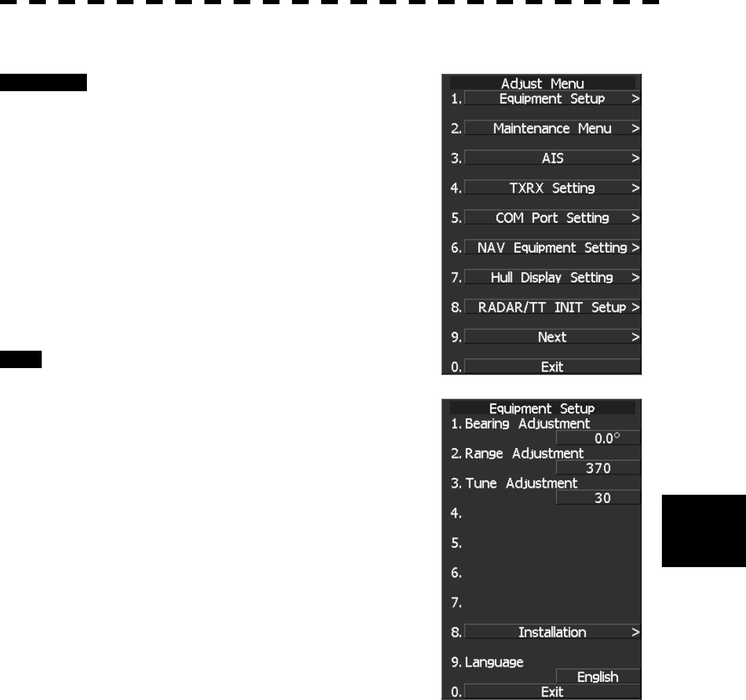
7.1 SETTINGS AT INSTALLATION
7─2
7
yyy
yyyy
7.1.1 How to open the Adjust Menu
Procedure 1 Continue to press [RADAR MENU] key.
The Code Input Menu will appear.
2 Press [0] key.
3 Move the cursor onto the “ENT” button
in the Code Input menu, and press
[ENT] key.
The Adjust Menu will appear.
4 Press [1] key.
The Equipment Setup Menu will appear.
Exit 1 Press [RADAR MENU] key.
The Main Menu will reappear.
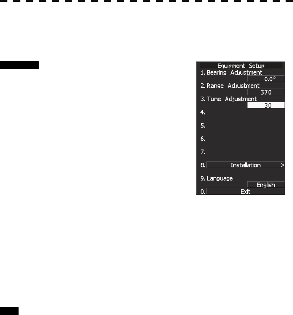
7─3
7.1.2 Tuning Adjustment
Adjust the tuning control for the transmitter and receiver.
The turning control should be adjusted when the system is installed or when the magnetron is replaced.
Procedure 1 Set a range of 24 NM or more.
2 Hold down [RADAR MENU] key.
The CODE Input screen opens.
3 Press [0] key.
The numeric keypad screen opens.
4 Place the cursor over the “ENT” button
of the numeric keypad and press [ENT]
key.
Adjust Menu opens.
5 Press [1] key.
Equipment Setup menu opens.
6 Press [3] key.
A numeric keypad screen for Tune Adjustment opens.
7 Adjust the value until the tuning state gauge reaches maximum by
inputting a value with the number keys or by turning the multi-dial to
change the value.
8 When the adjustment is complete, place the cursor over the “ENT”
button of the numeric keypad and press [ENT] key.
The adjustment value is memorized and the adjustment is complete.
Exit 1 Press [RADAR MENU] key.
The Main Menu will reappear.
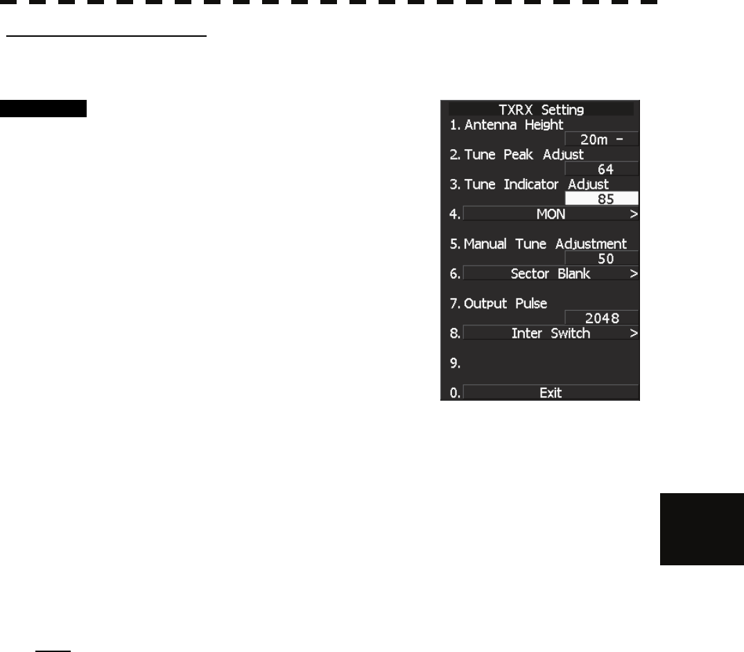
7.1 SETTINGS AT INSTALLATION
7─4
7
yyy
yyyy
[I] Tune Indicator Adjustment
Set the scale mark when the tune indicator bar reaches the maximum point.
Procedure 1 Set the range to 24 NM or more.
2 Hold down [RADAR MENU] key.
The CODE Input screen opens.
3 Press [0] key.
The numeric keypad screen opens.
4 Place the cursor over the “ENT” button
of the numeric keypad and press [ENT]
key.
Adjust Menu opens.
5 Press [4] key.
TXRX Setting menu opens.
6 Press [3] key.
The Tune Indicator numeric keypad screen opens.
7 Adjust the value until the tune indicator bar at the top left corner of the
screen reads 80% to 90% by inputting a value with the number keys or by
turning the multi-dial to change the value.
8 Place the cursor over the “ENT” button and press [ENT] key.
The tune level value is memorized and the level adjustment is complete.
Note: Do not let the tune indicator bar reach 100% while adjusting the tune level. The automatic tuning
function may not perform properly if the bar reaches 100%.
Set the level such that the tune indicator bar always reads 80% to 90%.
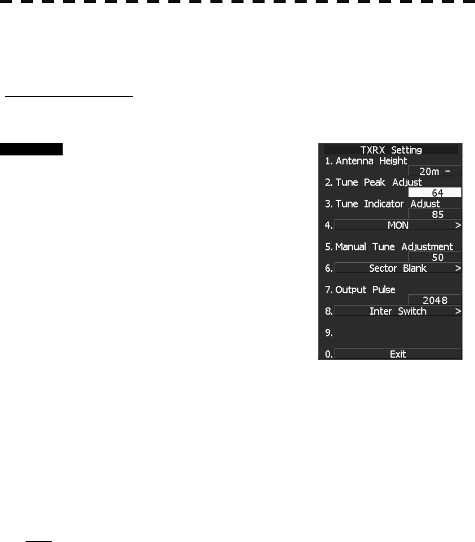
7─5
• With the JMA-5212 radar:
For this model, perform Tune Peak Adjustment and Tune Indicator Adjustment explained below.
After the above adjustment procedure, perform the adjustment procedure below.
[II] Tune Peak Adjustment
Adjust the tune indicator and echo peak.
Procedure 1 Set the range to 24 NM or more.
2 Hold down [RADAR MENU] key.
The CODE Input screen opens.
3 Press [0] key.
The numeric keypad screen opens.
4 Place the cursor over the “ENT” button
of the numeric keypad and press [ENT]
key.
Adjust Menu opens.
5 Press [4] key.
TXRX Setting menu opens.
6 Press [2] key.
The Tune Indicator numeric keypad screen opens.
7 Adjust the tune peak value until the tune indicator bar at the top left
corner of the screen reaches maximum by inputting a value with the
number keys or by turning the multi-dial to change the value.
8 Place the cursor over the “ENT” button and press [ENT] key.
The tune peak value is memorized and the peak adjustment is complete.
Note: Always set the tune peak adjustment value to 64.
When the equipment is used for a long time and the automatic tuning function no longer works properly,
adjusting the tune peak adjustment value may result in improvement of the automatic tuning function.
It should be noted that an optimal adjustment value is required for proper operation of the automatic
tuning function.
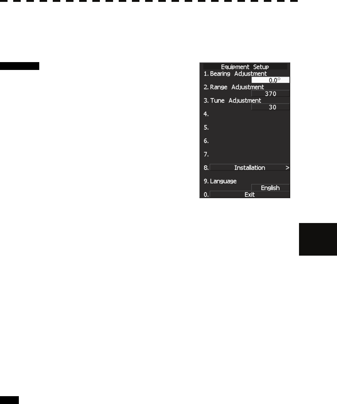
7.1 SETTINGS AT INSTALLATION
7─6
7
yyy
yyyy
7.1.3 Bearing Adjustment
Adjust the bearing so that bearing of the target measured with the ship’s compass matches that of the target
echo on the radar display.
Procedure 1 Press AZI MODE to select the relative
bearing presentation [H UP] mode. Set
Image Processing to OFF.
[AZI MODE] → Software button ⑧ located at
the top left corner of the radar display described
in Section 2.3.1 → Software button ④ located
at the bottom left corner of the radar display
described in Section 2.3.2.
2 Measure the bearing of an adequate
target (for example, a ship at anchor, a
breakwater or a buoy) relative to own
ship’s heading.
3 Hold down [RADAR MENU] key.
The Code Input Menu will appear.
4 Press [0] key.
5 Move the cursor onto the “ENT” button in the Code Input menu, and
press [ENT] key.
The Adjust Menu will appear.
6 Press [1] key.
Equipment Setup menu opens.
7 Press [1] key.
The Code Input Menu will appear.
8 Using numeric key, enter the value and then press “ENT” button, and
press “EXIT” button to determine the value.
The multi-function control can also be used to enter the value.
Make adjustment by the 0.1°.
9 Repeat Step 5 above, and adjust to display the target measured in Step 2
to the measured bearing.
Exit 1 Press [RADAR MENU] key.
The Main Menu will reappear.
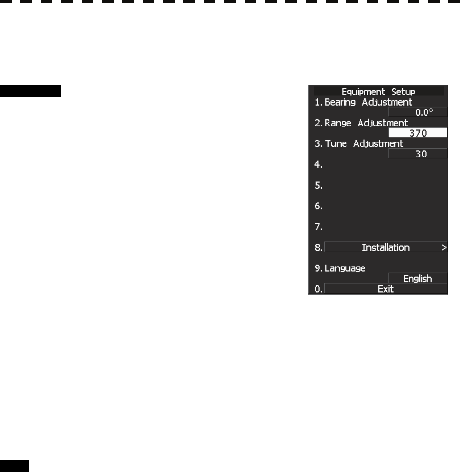
7─7
7.1.4 Range Adjustment
Adjust the range so that the range of the target on the radar video is indicated correctly.
Procedure 1 Search the radar display for a target of
which range is already known.
2 Hold down [RADAR MENU] key.
The Code Input Menu will appear.
3 Press [0] key.
4 Move the cursor onto the “ENT” button
in the Code Input menu, and press
[ENT] key.
The Adjust Menu will appear.
5 Press [1] key.
Equipment Setup menu opens.
6 Press [2] key.
The Code Input Menu will appear.
7 Using numeric pad, enter the value and then press “ENT” button, and
press “EXIT” button to determine the value.
The multi-function control can also be used to enter the value.
8 Repeat step 4, and adjust until the target range measured in step 1 and
the range on the radar display become identical.
Exit 1 Press [RADAR MENU] key.
The Main Menu will reappear.
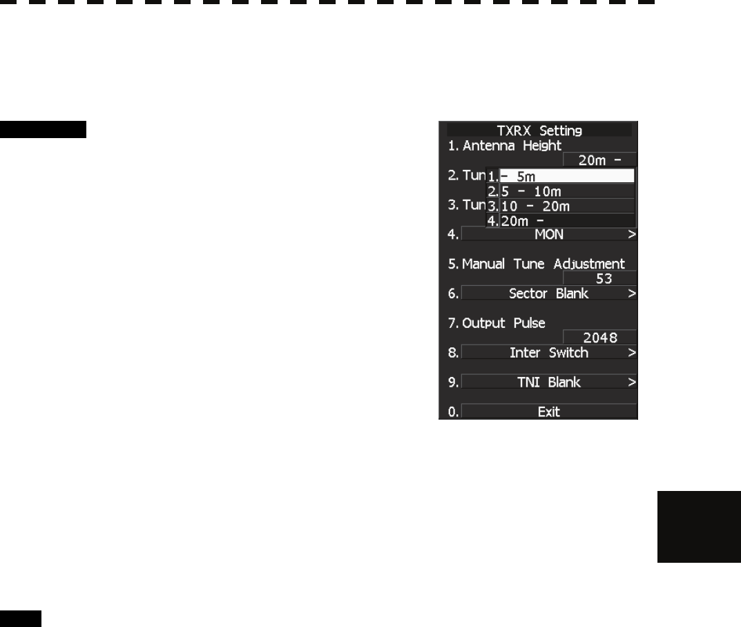
7.1 SETTINGS AT INSTALLATION
7─8
7
yyy
yyyy
7.1.5 Antenna Height Setting (Antenna Hight)
Set the antenna height above the sea level, but change this setting carelessly.
Procedure 1 Measure the height from the sea level to
the antenna in advance.
2 Hold down [RADAR MENU] key.
The Code Input Menu will appear.
3 Press [0] key.
4 Move the cursor onto the “ENT” button
in the Code Input menu, and press
[ENT] key.
The Adjust Menu will appear.
5 Press [4] key.
The TXRX Setting Menu will appear.
6 Press [1] key.
The Antenna Height Set Value window will appear.
7 Select the antenna height measured in step 1 from the pull-down menu
by pressing the numeric key [1] to [4].
The antenna height will be determined.
Exit 1 Press [RADAR MENU] key.
The Main Menu will reappear.
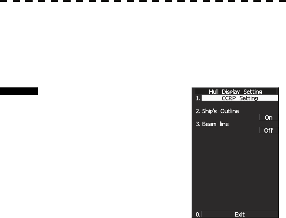
7─9
7.1.6 Setting of CCRP/Antenna/GPS Antenna Position (CCRP Setting)
Set the own ship's CCRP location, radar antenna installation location, and GPS installation location.
GPS : Up to 4 locations can be inputted (select one through the receiving port setting when using the
GPS).
Radar antenna : 1 location can be inputted (one master and one slave).
CCRP : 1 location can be inputted (another location is reserved as an antenna location).
Procedure 1 Measure the CCRP, radar antenna, and
GPS antenna positions beforehand.
2 Hold down [RADAR MENU] key.
The Code Input Menu will appear.
3 Press [0] key.
4 Move the cursor onto the “ENT” button
in the Code Input menu, and press
[ENT] key.
The Adjust Menu will appear.
5 Press the following keys.
7 Hull Display Setting
1 CCRP Setting
6 Input the vessel length in the Length field and the vessel width in the
Beam field at the top right corner of the CCRP Setting screen.
7 Move the cursor to the X and Y values of CCRP1. Press the ENT key
and input the CCRP1 position.
CCRP is on the starboard side of the ship when X>0 and is on the port side of the ship
when X<0.
8 In the same manner, input the GPS antenna and radar antenna positions.
9 Press [0] key and exit the CCRP setting screen.
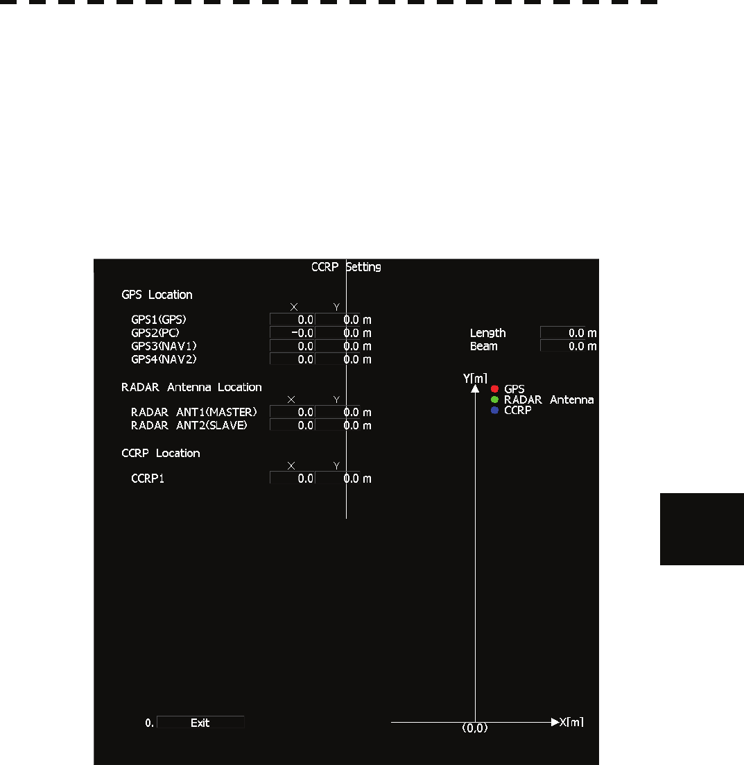
7.1 SETTINGS AT INSTALLATION
7─10
7
yyy
yyyy
GPS position :
If you wish to connect multiple GPS systems to a COM port and select a GPS position to be used, select it
through the receiving port setting of the GPS you wish to use.
Reference: Section 7.3.1.2 “Reception Port Setting (RX Port)”
Radar antenna position :
The radar antenna position changes as the antenna mode is switched between the master mode and the slave
mode by the simplified inter-switch.
CCRP position :
Only one position can be set.
If CCRP1 is outside the display area, ANT1 or ANT2 becomes the CCRP.
ANT1: Radar antenna position (MASTER)
ANT2: Radar antenna position (SLAVE)
CCRP is changed on the condition as following.
・ Radar antenna position is outside of the off center limit.
・ The CCRP position is outside of PPI.
This condition occurs with for example off center, true motion, turn of own ship, etc.