Japan Radio NKE2062 MARINE RADAR User Manual 4
Japan Radio Co Ltd. MARINE RADAR Users Manual 4
Contents
- 1. Users Manual 1
- 2. Users Manual 2
- 3. Users Manual 3
- 4. Users Manual 4
Users Manual 4
7─11
7.2 NAVIGATOR SETTING
This section describes the electrical adjustment procedures to be performed by service engineers during system
installation.
Make an appropriate setting for each type of equipment when inputting true bearing signals, true bearing data,
and speed data.
Settings and parameters are different for each type of equipment.
Make settings for the type of equipment to be connected.
[I] Inputting analog true bearing signals from a gyro system through
synchronization and steps
By following the procedure described in the INSTALLATION MANUAL, connect the optional NSK unit
(NCT-4106A) to this equipment. Then, follow the steps below to make settings.
In Section 7.2.1 “Ship Heading Equipment Setting (Heading Equipment),” select 1: GYRO (NCT-4106A,
JLR10, JRL20/30).
By referring to Section 7.2.2 “NSK Unit Setting,” make a setting for the gyro system.
By referring to Section 7.2.3 “True Bearing Value Setting (Set GYRO),” make a setting such that the gyro
azimuth and the radar azimuth are the same.
Refer to an applicable page for details.
CAUTION
Do not carry out the adjustments of the equipment
except authorized service persons. If wrong setting is
carried out, this may cause unstable operation.
Do not carry out the adjustments during navigation.
Otherwise, the radar performance may be affected,
resulting in an accident or trouble.

7.2 NAVIGATOR SETTING
7─12
7
yyy
yyyy
[II] Inputting digital true bearing signals from a gyro system (IEC61162, NMEA0183)
By following the procedure described in the INSTALLATION MANUAL, connect the gyro system to this
equipment. Then, follow the steps below to make settings.
In Section 7.2.1 “Ship Heading Equipment Setting (Heading Equipment),” select 2: COMPASS (IEC61162).
In Section 7.3.1.1 “Baud Rate Setting,” select 5. COM5 (COMPASS).
Select either 38400 bps or 48000 bps depending on the data baud rate outputted from the GPS compass.
(*) For digital signal output from the gyro system
・ Select 38400 bps if possible. A higher baud rate means shorter data output cycle, which results in
better course following performance.
・ If the system allows setting of data output cycle, set it to 10 ms to 20 ms.
A longer data output cycle results in lower course following performance. This may affect the
radar performance level and the target tracking performance level.
Refer to an applicable page for details.
[III] Inputting true bearing data from GPS Compass JLR10 or JLR20/30
By following the procedure described in the INSTALLATION MANUAL, connect GPS Compass JLR10 or
JLR20/30 to this equipment. Then, follow the steps below to make settings.
In Section 7.2.1 “Ship Heading Equipment Setting (Heading Equipment),” select 1: GYRO (NCT-4106A,
JLR10, JRL20/30).
True bearing value setting described in Section 7.2.3 is not required when using the GPS compass.
If the GPS compass azimuth and the radar azimuth are not the same, use the GPS compass to adjust the
azimuth.
Refer to an applicable page for details.
[IV] Inputting digital true bearing data from a GPS compass (other than JLR10 and
JLR20/30) or other true bearing systems (IEC61162 or NMEA0183)
By following the procedure described in the INSTALLATION MANUAL, connect a GPS compass or other true
bearing system to this equipment. Then, follow the steps below to make settings.
In Section 7.2.1 “Ship Heading Equipment Setting (Heading Equipment),” select 2: COMPASS (IEC61162).
In Section 7.3.1.1 “Baud Rate Setting,” select 5. COM5 (COMPASS).
Select either 38400 bps or 48000 bps depending on the data baud rate outputted from the GPS compass.
(*) For the GPS compass or other true bearing systems
・ Select 38400 bps if possible. A higher baud rate means shorter data output cycle, which results in
better course following performance.
・ If the system allows setting of data output cycle, set it to 10 ms to 20 ms.
A longer data output cycle results in lower course following performance. This may affect the
radar performance level and the target tracking performance level.
Refer to an applicable page for details.

7─13
[V] Inputting analog speed signals from a log system through synchronization and
steps
By following the procedure described in the INSTALLATION MANUAL, connect the optional NSK unit
(NCT-4106A) to this equipment. Then, follow the steps below to make settings.
In Section 7.2.5 “Ship Speed Equipment Setting (Speed Equipment),” select 2: LOG.
Refer to an applicable page for details.
[VI] Inputting digital speed data using a current meter or a Doppler sonar
(IEC61162 or NMEA0183)
By following the procedure described in the INSTALLATION MANUAL, connect speed equipment to this
equipment. Then, follow the steps below to make settings.
In Section 7.2.5 “Ship Speed Equipment Setting (Speed Equipment),” select 3: 2 AXIS W to use the sea speed.
Select 4: 2 AXIS G to use the ground speed.
Refer to an applicable page for details.
[VII] Inputting GPS speed data (IEC61162 or NMEA0183)
By following the procedure described in the INSTALLATION MANUAL, connect speed equipment to this
equipment. Then, follow the steps below to make settings.
In Section 7.2.5 “Ship Speed Equipment Setting (Speed Equipment),” select 5: GPS.
Refer to an applicable page for details.
[VIII] Inputting speed data manually
In Section 7.2.5 “Ship Speed Equipment Setting (Speed Equipment),” select 1: Manual.
In Section 7.2.6 “Manual Speed Setting (Manual Speed),” input the speed manually using the numeric keypad
or multi-dial.
Refer to an applicable page for details.
7.2 NAVIGATOR SETTING
7─14
7
yyy
yyyy
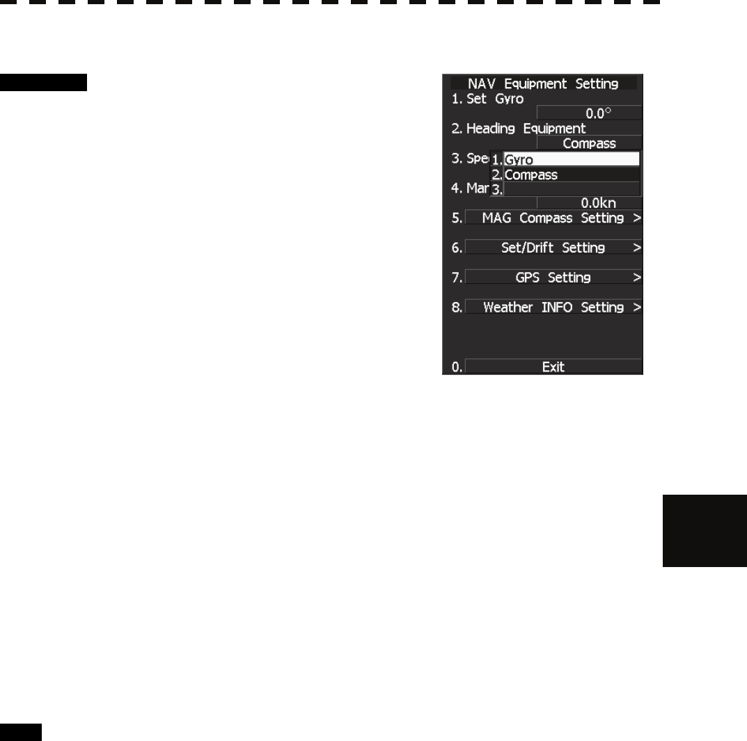
7.2.1 Ship Heading Equipment Setting (Heading Equipment)
Procedure 1 Press [RADAR MENU] key.
Main Menu opens.
2 Press [7] key.
NAV Equipment Setting menu opens.
3 Press [2] key.
Heading Equipment settings are displayed.
4 From the pull-down menu, select
heading equipment.
1 : GYRO (NCT-4106A, JLR10, JLR20/30)
2 : COMPASS (IEC61162)
<The alternative procedure for steps above>
1 Hold down [RADAR MENU] key.
The Code Input Menu will appear.
2 Press [0] key.
3 Move the cursor onto the “ENT” button in the Code Input menu, and
press [ENT] key.
The Adjust Menu will appear.
4 Press [6] key.
NAV Equipment Setting menu opens.
5 Perform steps 3 and 4 in the “Procedure” above.
Exit 1 Press [RADAR MENU] key.
Menu closes.

7─15
7.2.2 NSK Unit Setting
The NSK Unit circuit of the system is designed to be compatible with most types of gyro compasses by simply
setting the switches.
Step motor type: 20 to 170 VDC
Synchro-motor type: Primary excitation voltage 35 to 120 VAC
Before power-on operation can be performed, the switches S1 to S5 on the NSK Unit circuit (PC4201) must be
set in accordance with the type of your gyro compass by performing the procedure below. The switches are
factory-set for a gyration ratio of 180X and the step motor type. Make sure of the type of the gyro compass
installed on the own ship before starting the procedure below.
Procedure 1 Set S1 to "OFF."
The gyro compass and NSK Unit are turned off.
2 Set S2 and S3 in accordance with the type of your gyro compass.
There are two types of gyro compasses: one type outputs a step signal, and the other type
outputs a synchro signal. Make sure of the type of the gyro compass installed on the own
ship before setting the switches S2 and S3.
Synchro signal: Set the switches to [SYNC].
Step signal: Set the switches to [STEP].
3 Set the DIP switch S4.
The items to be set are listed below. For the settings, refer to Table 7-1.
S4-1: LOG alarm ON/OFF
S4-2: GYRO simulator ON/OFF
S4-3: LOG simulator ON/OFF
S4-5: Time before occurrence of GYRO alarm
S4-6: Sensor to be used (GYRO/NMEA)
S4-7/8: Baud rate when NMEA is used
4 Set the DIP switch S5.
The items to be set are listed below. For the setting, refer to Table 7-2.
S5-1: Type of gyro signal (step/synchro)
S5-2/3: Gyration ratio of gyro compass
S5-4: Gyration direction of gyro compass
S5-5: Type of log signal (pulse/synchro)
S5-7/8: Ratio of log signal
5 Connect the gyro signal and log signal cables to the terminal block.
6 Set S1 to "ON."
The gyro compass and NSK Unit are connected.
7 After power-on operation, set the true bearing according to Section 7.2.3.
8 Make sure of the radar video and the operation with the true bearing
value.
9 If the true bearing value of the radar equipment is reversed, change the
setting of the switch S5-4.
7.2 NAVIGATOR SETTING
7─16
7
yyy
yyyy
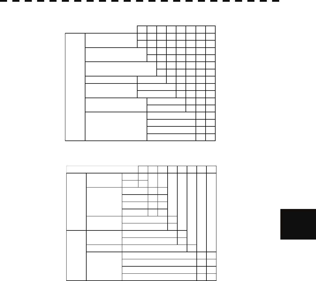
Table 7-1 Setting Table (S4 DIP Switch)
Table 7-2 Setting Table (S5 DIP Switch)
12345678
ON
OFF
ON
OFF
ON
OFF
any
ON
OFF
ON
OFF
OFF OFF
ON OFF
OFF ON
ON ON
NMEA BAUDRATE
SETTING
5s
0.5s
4800
9600
19200
38400
HEADING SENSOR
SOURCE
NMEA(HDT/THS)
GYRO SIGNAL
OTHER SETTING
LOG ALARM
GYRO SIMULATOR
LOG SIMULATOR
N.C. Don't care
GYRO ALARM
TIME
12345678
STEP ON
SYNC OFF
ON ON
OFF ON
ON OFF
OFF OFF
ON
OFF
ON
OFF
N.C. any
ON ON
OFF ON
ON OFF
OFF OFF
ジャイロ信号
GYRO SIG
ログ信号
LOG SIG
TYPE
タイプ
TYPE
シンクロ/SYNC
パルス/PULSE
Don't care
パルス
PULSE
100P/30×
RATIO
36×
90×
180×
360×
回転方向
DIRECTION
逆/REV
200P/90×
400P/180×
800P/360×
正/NOR
GYRO SIG LOG SIG
DIRECTION
TYPE
PULSE
SYNC
PULSE
REV
NOR
7─17
7.2.3 True Bearing Value Setting (Set GYRO)
Adjust the bearing that the bearing angle of the radar is the same as that of the gyro.
When the NSK unit is used to input gyro signals, in rare cases, the true bearing value indicated by the master
gyro and the true bearing value indicated by this equipment do not agree with each other. If this occurs, make
the setting described below to adjust the true bearing value of this equipment to the value indicated by the
master gyro.
This setting is available only when the NSK unit NCT-4106A is used.
Procedure 1 Press [RADAR MENU] key twice.
The Main Menu will appear.
2 Press [7] key.
The NAV Equipment Setting Menu will appear.
3 Press [1] key.
The Code Input Menu will appear.
4 Adjust true bearing value.
Adjust the bearing that the bearing angle of the
radar is the same as that of the gyro.
The multi-function control can also be used to
enter the value.
After having entered the value, move the cursor onto the “ENT” button and press [ENT] key.
<The alternative procedure for steps above>
1 Hold down [RADAR MENU] key.
The Code Input Menu will appear.
2 Press [0] key.
3 Move the cursor onto the “ENT” button in the Code Input menu, and
press [ENT] key.
The Adjust Menu will appear.
4 Press [6] key.
NAV Equipment Setting menu opens.
5 Perform steps 3 and 4 in the “Procedure” above.
Exit 1 Press [RADAR MENU] key.
The menu will be closed.

7.2 NAVIGATOR SETTING
7─18
7
yyy
yyyy
7.2.4 MAG Compass Setting
Set the MAG compass.
Procedure 1 Press [RADAR MENU] key twice.
The Main Menu will appear.
2 Press [7] key.
NAV Equipment Setting Menu will appear.
3 Press [5] key.
MAG Compass Setting Menu will appear.
4 Press [1] key.
This item is set as to whether or not the heading
bearing is to be corrected. Switching between
ON and OFF is done each time you press
[1] key
.
5 Press [2] key.
The Code Input Menu will appear.
6 Pressing a numeric key, enter the value. Select “ENT” and then
determine the value.
The correction direction and angle will be set. On the screen, press “+” to make
correction in the eastern direction, and press “-” to make correction in the western
direction. Also enter a correction angle, pressing the numeric key.
The multi-function control is also available for the entry. To do so, enter the correction
direction, press the multi-function control, enter the correction angle, and then set ENT in order.
<The alternative procedure for steps above>
1 Hold down [RADAR MENU] key.
The Code Input Menu will appear.
2 Press [0] key.
3 Move the cursor onto the “ENT” button in the Code Input menu, and
press [ENT] key.
The Adjust Menu will appear.
4 Press [6] key.
NAV Equipment Setting menu opens.
5 Perform steps 3 to 6 in the “Procedure” above.
Exit 1 Press [RADAR MENU] key.
The menu will be closed.
7─19
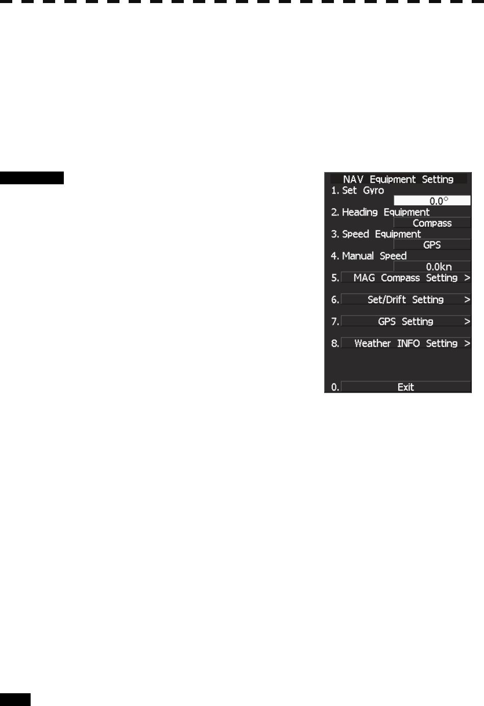
7.2.5 Ship Speed Equipment Setting (Speed Equipment)
Procedure 1 Press [RADAR MENU] key twice.
The Main Menu will appear.
2 Press [7] key.
The NAV Equipment Setting Menu will appear.
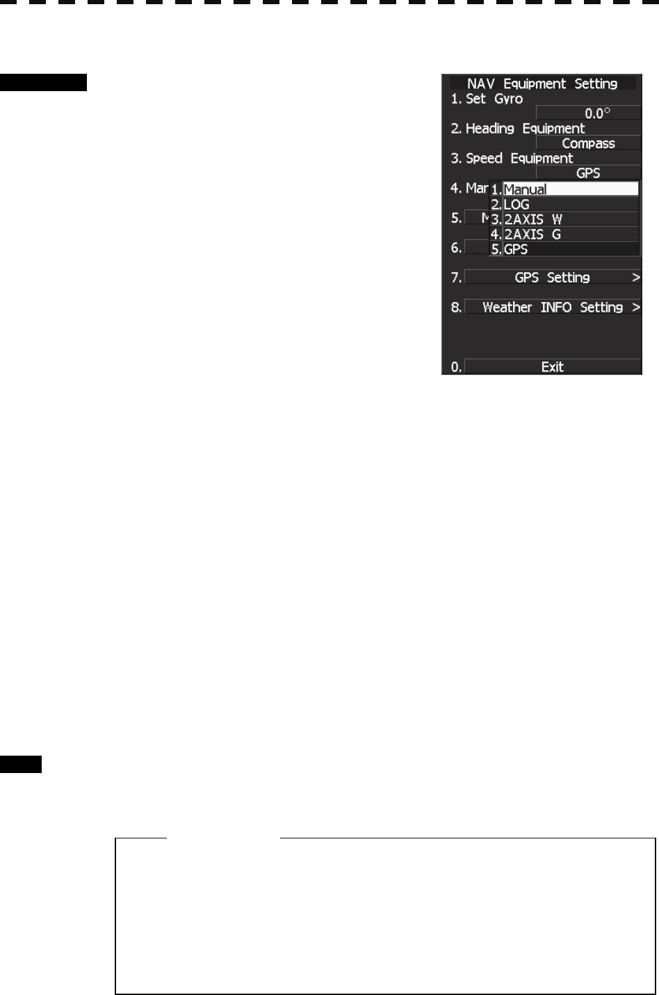
3 Press [3] key.
4 Select a ship speed sensor from the
pull-down menu.
Types of selectable speed sensors:
1: Manual
2: Log
3: 2-axis log (NMEA signal: Speed over water)
4: 2-axis log (NMEA signal: Speed over ground)
5: GPS
<The alternative procedure for steps above>
1 Hold down [RADAR MENU] key.
The Code Input Menu will appear.
2 Press [0] key.
3 Move the cursor onto the “ENT” button in the Code Input menu, and
press [ENT] key.
The Adjust Menu will appear.
4 Press [6] key.
NAV Equipment Setting menu opens.
5 Perform steps 3 and 4 in the “Procedure” above.
Exit 1 Press [RADAR MENU] key.
The menu will be closed.
z The manually entered speed is effective only when
“Manual” is set.
z 2-axis log cannot be effective when the sentence
VBW of NMEA0183 is not entered.
Attention
7.2 NAVIGATOR SETTING
7─20
7
yyy
yyyy
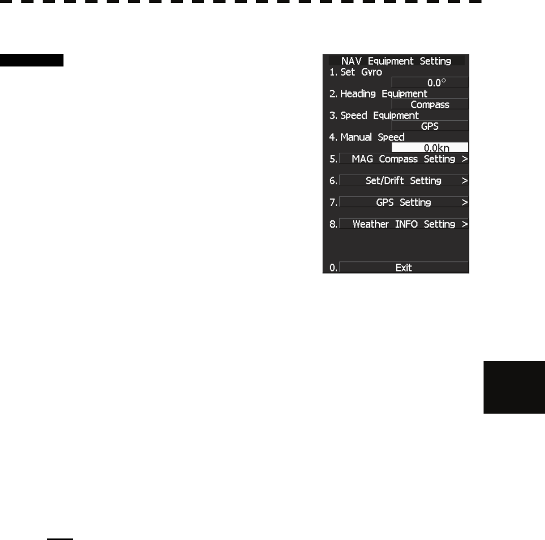
7.2.6 Manual Speed Setting (Manual Speed)
Procedure 1 Press [RADAR MENU] key twice.
The Main Menu will appear.
2 Press [7] key.
NAV Equipment Setting Menu will appear.
3 Press [4] key.
The Code Input menu will appear.
4 Pressing a numeric key, enter the value
and select “ENT.”
The multi-function control is also available for
the entry.
<The alternative procedure for steps above>
1 Hold down [RADAR MENU] key.
The Code Input Menu will appear.
2 Press [0] key.
3 Move the cursor onto the “ENT” button in the Code Input menu, and
press [ENT] key.
The Adjust Menu will appear.
4 Press [6] key.
NAV Equipment Setting menu opens.
5 Perform steps 3 and 4 in the “Procedure” above.
Note: The manually entered speed is effective only when “Manual” is set.
7─21
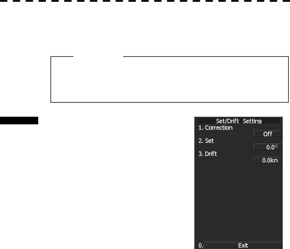
7.2.7 Current Correction (SET/DRIFT) Setting
The current set and drift will be set.
Procedure 1 Press [RADAR MENU] key twice.
The Main Menu will appear.
2 Press [7] key.
The NAV Equipment Setting Menu will appear.
3 Press [6] key.
The Set/Drift Setting Menu will appear.
4 Press [1] key to enable Correction.
The setting of Correction is switched back and
forth between ON and OFF each time [1] key is
pressed.
Off : Do not perform current correction.
On : Perform current correction.
5 Press [2] key.
The Code Input Menu will appear.
6 Enter the direction of tendency.
The direction of tendency will be set. The multi-function control is also available for the
entry.
After having entered the direction, move the cursor onto the “ENT” button and press
[ENT] key.
7 Press [3] key.
The Code Input Menu will appear.
8 Enter the speed of tendency.
The speed of tendency will be set. The multi-function control is also available for the
entry.
After having enter the value, move the cursor onto the “ENT” button and press [ENT] key.
z The manually entered speed is effective only when
“Speed Equipment” is set to “Manual” or “LOG”.
Attention

7.2 NAVIGATOR SETTING
7─22
7
yyy
yyyy
<The alternative procedure for steps above>
1 Hold down [RADAR MENU] key.
The Code Input Menu will appear.
2 Press [0] key.
3 Move the cursor onto the “ENT” button in the Code Input menu, and
press [ENT] key.
The Adjust Menu will appear.
4 Press [6] key.
NAV Equipment Setting menu opens.
5 Perform steps 3 to 8 in the “Procedure” above.
Exit 1 Press [RADAR MENU] key.
The menu will be closed.
7─23
7.3 SETTINGS
This section describes the electrical adjustment procedures to be performed by service engineers during system
installation.
7.3.1 Communication Port Setting (COM Port Setting)
External sensor signals are input to the radar equipment through a communication port. The radar equipment
has five communication ports. For signals to be input from sensors or to be output to the sensors,
communication ports need to be set in accordance with the sensors.
CAUTION
Do not carry out the adjustments of the equipment
except authorized service persons. If wrong setting is
carried out, this may cause unstable operation.
Do not carry out the adjustments during navigation.
Otherwise, the radar performance may be affected,
resulting in an accident or trouble.
7.3 SETTINGS
7─24
7
yyy
yyyy
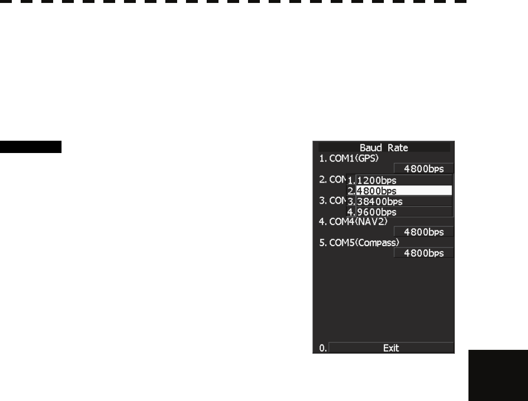
7.3.1.1 Baud Rate Setting
Set the baud rate of the signal to be entered into the COM port.
Each ports on the menu represents following connectors.
COM1(GPS) J3 GPS
COM2(PC) J8 NMEA
COM3(NAV1) J6 AIS/NMEA
COM4(NAV2) J9 AUX
COM5(NSK/COMPASS) J5 GYRO COMPASS
Procedure 1 Hold down [RADAR MENU] key.
The Code Input Menu will appear.
2 Press [0] key.
3 Move the cursor onto the “ENT” button
in the Code Input menu, and press
[ENT] key.
The Adjust Menu will appear.
4 Press [5] key.
The COM Port Setting Menu will appear.
5 Press [1] key.
The Baud Rate Setting Menu will appear.
6 Select the port number you want to set, pressing the numeric keys [1] to
[5].
The Baud Rate Selection menu will appear.
7 In the selection menu, select the baud rate you want to set, pressing the
numeric key.
Selection value
1. COM1 (GPS): 1200/4800/*38400/9600 bps
2. COM2 (PC): 1200/4800/38400/115200/9600 bps
3. COM3 (NAV1): 1200/4800/38400/9600 bps
4. COM4 (NAV2): 1200/4800/*38400/9600 bps
5. COM5 (COMPASS): 4800/38400 bps
* If COM1/COM4 is set to 38400 bps, signals can only be transmitted. The baud rate
for reception can be set to up to 4800 bps.
COM5 can be used for receive port only. It is dedicated for COMPASS signal. This
means that the port is unavailable for other signals.
The GPS, PC, NAV1, NAV2, COMPASS in the parentheses are the standard ports
connecting to the external sensors.
When an AIS unit is used, COM3 is used exclusively for the AIS.
Connect the AIS to COM3.
Use a port other than COM3 when connecting a device other than an AIS unit.
An external device can be connected to COM3 when an AIS unit is not used.
When a baud rate of 1200 bps is selected, a 1200 bps JRC format is used.

7─25
Exit 1 Press [RADAR MENU] key.
The Main Menu will reappear.
7.3 SETTINGS
7─26
7
yyy
yyyy
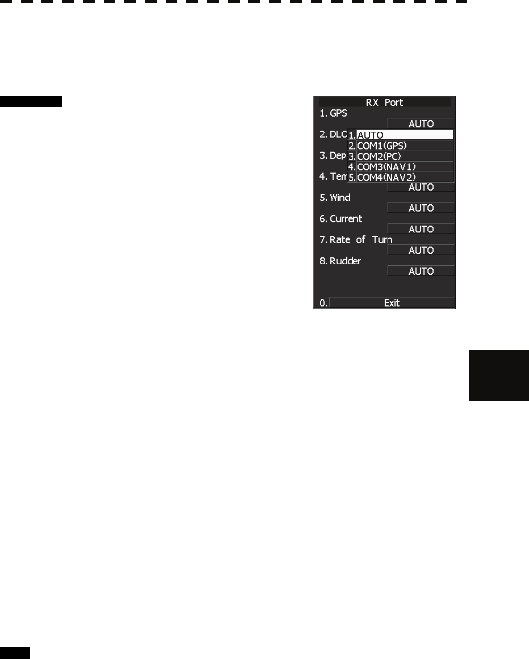
7.3.1.2 Reception Port Setting (RX Port)
Set the number of the port via which signals are received from sensors.
There are two methods for receiving signals: specifying a port for each sensor, or using the automatic
recognition function without specifying ports.
Procedure 1 Hold down [RADAR MENU] key.
The Code Input Menu will appear.
2 Press [0] key.
3 Move the cursor onto the “ENT” button
in the Code Input menu, and press
[ENT] key.
The Adjust Menu will appear.
4 Press [5] key.
The COM Port Setting Menu will appear.
5 Press [4] key.
The RX Port Menu will appear.
6 Select the signal you want to set, pressing the numeric keys [1] to [6].
The Reception Port Setting Menu for each signal will appear.
Settable signals
1. GPS
2. DLOG
3. Depth
4. Temperature
5. Wind
6. Current
7. Rate of Turn
8. Rudder
7 Select which port you want to use for output.
Types of ports to be used
1. AUTO
2. COM1 (GPS)
3. COM2 (PC)
4. COM3 (NAV1)
5. COM4 (NAV2)
* For AUTO, the initial value will be selected.
Select the number of the port to be used, pressing the numeric key.
Exit 1 Press [RADAR MENU] key.
The Main Menu will reappear.
7─27
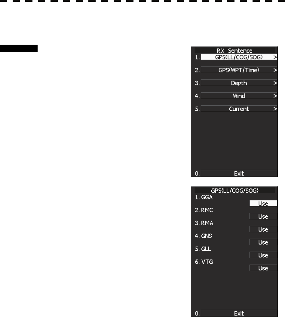
7.3.1.3 Reception Sentence Setting (RX Sentence)
Set signal sentences to be received from sensors.
Procedure 1 Hold down [RADAR MENU] key.
The Code Input Menu will appear.
2 Press [0] key.
3 Move the cursor onto the “ENT” button
in the Code Input menu, and press
[ENT] key.
The Adjust Menu will appear.
4 Press [5] key.
The COM Port Setting Menu will appear.
5 Press [2] key.
The RX Sentence Menu will appear.
6 Select the signal you want to set,
pressing the numeric keys [1] to [3].
The Setting Menu for each signal will appear.
Settable signal
1. GPS (LL/COG/SOG)
2. GPS (WPT)
3. Depth
4. Wind
5. Current
7 Select whether or not you want to use
sentence for the signal.
Types of sentences to be used
GPS (LL/COG/SOG): GGA/RMC/RMA/GNS/
GLL/VTG
GPS (WPT): GGA/RMC/RMB/
BWC/BWR/ZDA
Depth: DPT/DBK/DBT/DBS
Wind: MWV/MWD
Current: CUR
After having selected a signal, choose the number of the sentence for which you want to
set whether or not it is used, pressing the numeric key.
As concerns current, set layer number of CUR sentence.
↓

7.3 SETTINGS
7─28
7
yyy
yyyy
Layer A:
0-999. Set the number of the sentence to be used with layer A by Layer Number.
(Initial value 3)
Layer B:
0-999. Set the number of the sentence to be used with layer B by Layer Number.
(Initial value 4)
Layer C:
0-999. Set the number of the sentence to be used with layer C by Layer Number.
(Initial value 5)
Exit 1 Press [RADAR MENU] key.
The Main Menu will reappear.
7─29
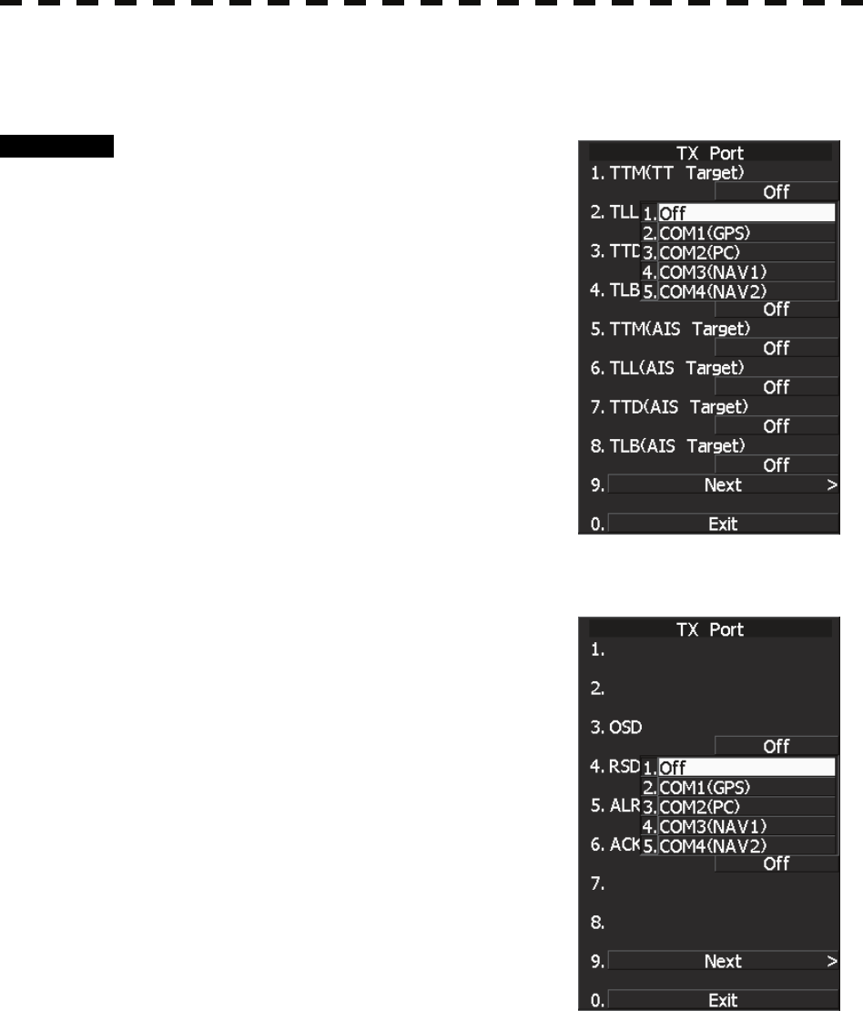
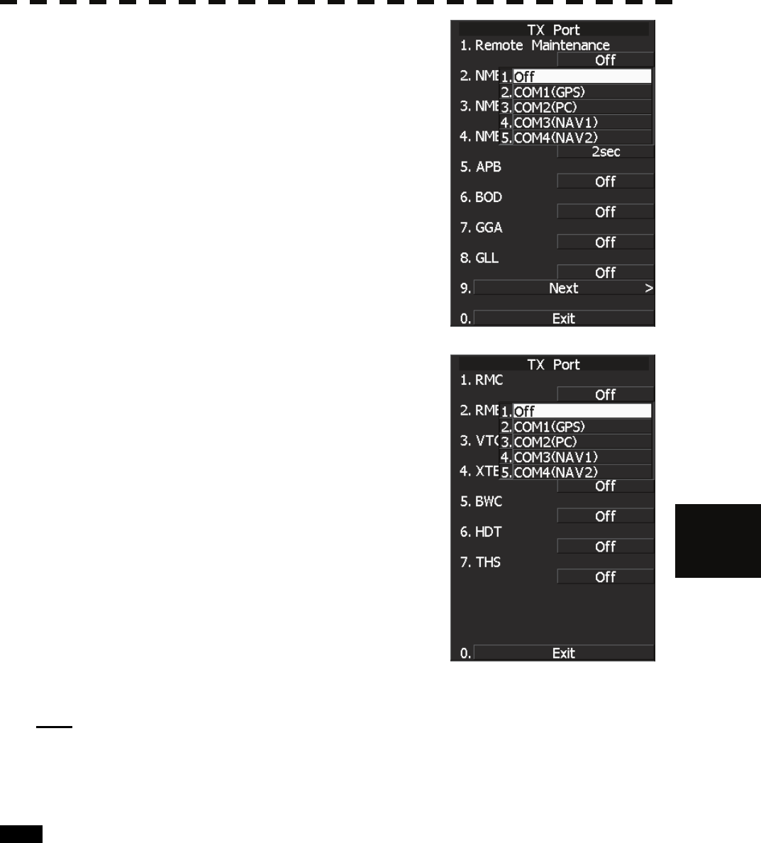
7.3.1.4 Transmission Port Setting (TX Port)
For each sentence, set a communication port through which signals are transmitted to sensors.
Procedure 1 Hold down [RADAR MENU] key.
The Code Input Menu will appear.
2 Press [0] key.
3 Move the cursor onto the “ENT” button
in the Code Input menu, and press
[ENT] key.
The Adjust Menu will appear.
4 Press [5] key.
Press [3] key.
The TX Port Menu will appear.
5 Select the signal you want to set,
pressing the numeric keys [1] to [9].
The Output Port Setting Menu for each signal will appear.
Settable sentences
1. TTM(TT Target)
2. TLL(TT Target)
3. TTD(TT Target)
4. TLB(TT Target)
5. TTM(AIS Target)
6. TLL(AIS Target)
7. TTD(AIS Target)
8. TLB(AIS Target)
↓
1.
2.
3. OSD
4. RSD
5. ALR
6. AIS
7.
8.
↓
1. Remote Maintenance
2. NMEA0183 Output Format
3. NMEA0183 Talker
4. NMEA0183 TX Interval
5. APB
6. BOD
7. GGA
8. GLL
↓
1. RMC
2. RMB
3. VTG
4. XTE
5. BWC
7.3 SETTINGS
7─30
7
yyy
yyyy
6. HDT
7. THS
6 Select which port you want to use for
output.
Types of ports to be used
1. OFF
2. COM1 (GPS)
3. COM2 (PC)
4. COM3 (NAV1)
5. COM4 (NAV2)
Select the number of the port to be used, pressing
the numeric key.
7 Select the output format, talker, and
transmission interval.
Signals for which the above items can be set:
• NMEA0183 Output Format
Signal names: APB, BOD, GGA, GLL, RMC,
RMB,VTG, XTE, BWC, HDT, THS
Selection Value: V1.5, V2.0, and V2.3
• NMEA0183 Talker
Signal names: APB, BOD,RMB, XTE, BWC,
HDT, THS
Selection Value:
Standard: The talker is RA.
GP: The talker is GP.
For TTM, TLL, TTD, TLB, OSD, RSD, ALR,
and AIS, the talker is always RA .
For GGA, GLL, RMC, and VTG, the talker is
always GP.
• NMEA0183 TX Interval
Signal names: APB, BOD, GGA, GLL, RMC,
RMB,VTG, XTE, BWC, HDT, THS
Selection Value: Set an interval in the range 1 to 9 seconds.
Note: When multiple output sentences are selected, data may not be transmitted at the selected transmission
interval.
In particular, the volume of TTM, TLL, TLB, and TTD data containing TT and AIS target information
increases as the number of targets increases, and as a result, the transmission interval becomes longer.
Exit 1 Press [RADAR MENU] key.
The Main Menu will reappear.
* Note that, if you set COM1 and COM4 for transmission, they cannot be used as reception ports.
7─31
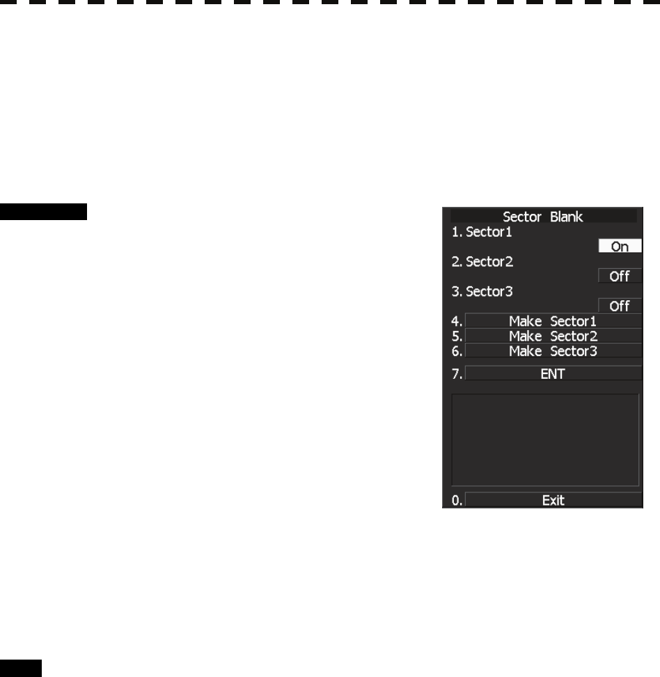
7.3.2 Sector Blank Setting (Sector Blank)
Set a sector range, preventing displaying the radar echo only within the area. Three types of sector can be
created.
The sector blank function operates in the relative bearing with the bow.
Note: This function can be performed only when the scanner is connected to NKE-2103 and NKE-2254.
[I] Turning ON/OFF the Sector function (Sector 1, 2 and 3)
Procedure 1 Hold down [RADAR MENU] key.
The Code Input Menu will appear.
2 Press [0] key.
3 Move the cursor onto the “ENT” button
in the Code Input menu, and press
[ENT] key.
The Adjust Menu will appear.
4 Press [4] key.
Press [6] key.
The Sector Blank Menu will appear.
5 Select the number you want to excuted
sector blank, Pressing the numeric
keys [1] to [3].
The system allows the use of up to three sector blank areas.
Set each sector blank area to on or off.
On: The sector blank function is operated.
Off: The sector blank function is stopped.
Exit 1 Press [RADAR MENU] key.
The Main Menu will reappear.
7.3 SETTINGS
7─32
7
yyy
yyyy
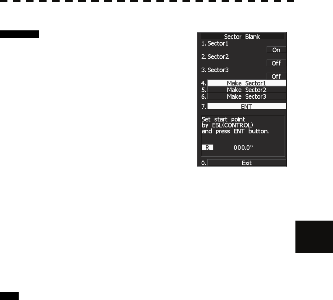
[II] Making Sector Function (Make Sector 1, 2, 3)
Procedure 1 Transmit the radar.
2 Hold down [RADAR MENU] key.
The Code Input Menu will appear.
3 Press [0] key.
4 Move the cursor onto the “ENT” button
in the Code Input menu, and press
[ENT] key.
The Adjust Menu will appear.
4 Press [4] key.
Press [6] key.
The Sector Blank Menu will appear.
5 Slect the number you want to make sector blank, pressing the numeric
keys [4] to [6].
The sector blank for the numeric key pressed will be made.
6 Set the start point of the sector blank by operating the [EBL] dial, and
then press 7 ENT.
The start angle of the sector blank will be set.
7 Set the end point of the sector blank by operating the [EBL] dial, and
then press 7 ENT.
The end angle of the sector blank will be set.
Exit 1 Press [RADAR MENU] key.
The Main Menu will reappear.
7─33
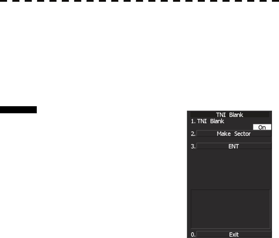
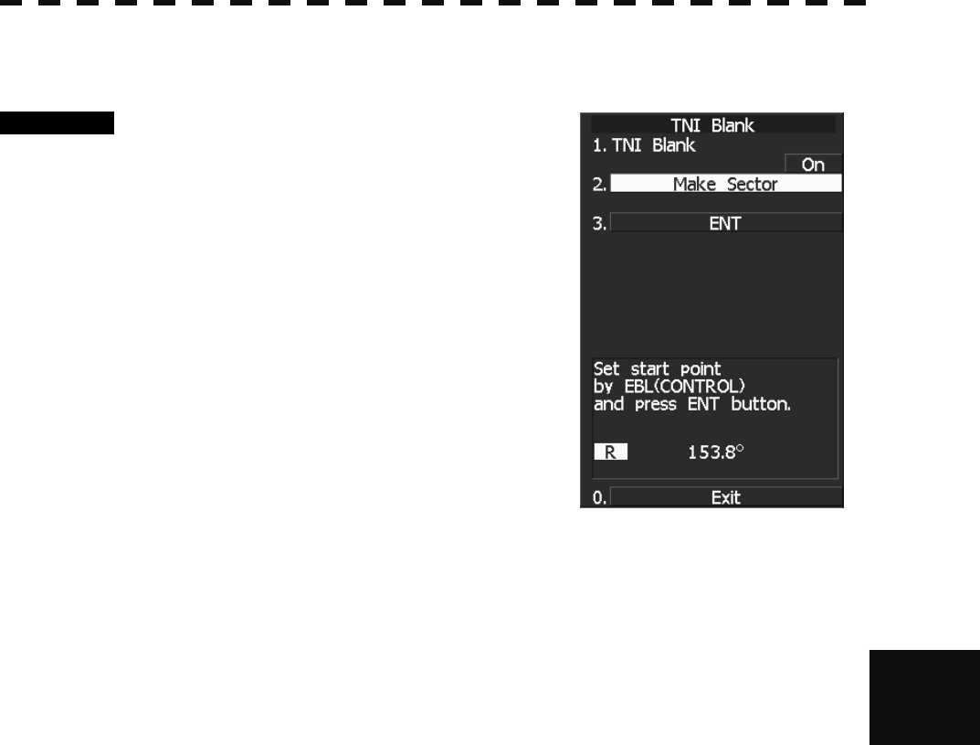
7.3.3 TNI Blank Setting (TNI Blank)
Set a sector and stop tuning operation in the bearing.
If a structure such as the mast is close to the radar antenna, automatic tuning operation may become unstable. In
this case, set a TNI blank in the direction of the structure in order to stabilize the tuning operation.
Only one TNI blank sector can be created. The TNI blank function operates in the relative bearing with the
bow.
Note: This function can be performed only when the scanner is connected to NKE-2103 and NKE-2254.
[I] TNI Blank Function On/Off (Sector)
Procedure 1 Hold down [RADAR MENU] key.
The Code Input Menu will appear.
2 Press [0] key.
3 Move the cursor onto the “ENT” button
in the Code Input menu, and press
[ENT] key.
The Adjust Menu will appear.
4 Press the following keys.
4 TXRX Setting
9 TNI Blank
1 TNI Blank
On: The TNI blank function is operated.
Off: The TNI blank function is stopped.
7.3 SETTINGS
7─34
7
yyy
yyyy
[II] TNI Blank Area Creation (Make Sector)
Procedure 1. Transmit the radar.
2 Hold down [RADAR MENU] key.
The Code Input Menu will appear.
3 Press [0] key.
4 Move the cursor onto the “ENT” button
in the Code Input menu, and press
[ENT] key.
The Adjust Menu will appear.
5 Press the following keys.
4 TXRX Setting
9 TNI Blank
2 Create sector
6 Set the starting bearing of the TNI blank by operating the [EBL] dial, and
press the [ENT] key.
7 Set the ending bearing of the TNI blank by operating the [EBL] dial, and
press the [ENT] key.
The TNI blank area is set.
7─35
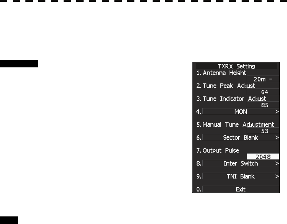
7.3.4 Bearing Pulse Output Adjustment (Output Pulse)
Set the output value of bearing pulse. This radar can set the output value to 2048 pulses and 4096 pulses.
This setting is allowed only when a 25 kw antenna is used.
Procedure 1 Hold down [RADAR MENU] key.
The Code Input Menu will appear.
2 Press [0] key.
3 Move the cursor onto the “ENT” button
in the Code Input menu, and press
[ENT] key.
The Adjust Menu will appear.
4 Press [4] key.
The TXRX Setting Menu will appear.
5 Press [7] key.
6 Select a set value to be used.
Exit 1 Press [RADAR MENU] key.
The Main Menu will reappear.
7.3 SETTINGS
7─36
7
yyy
yyyy
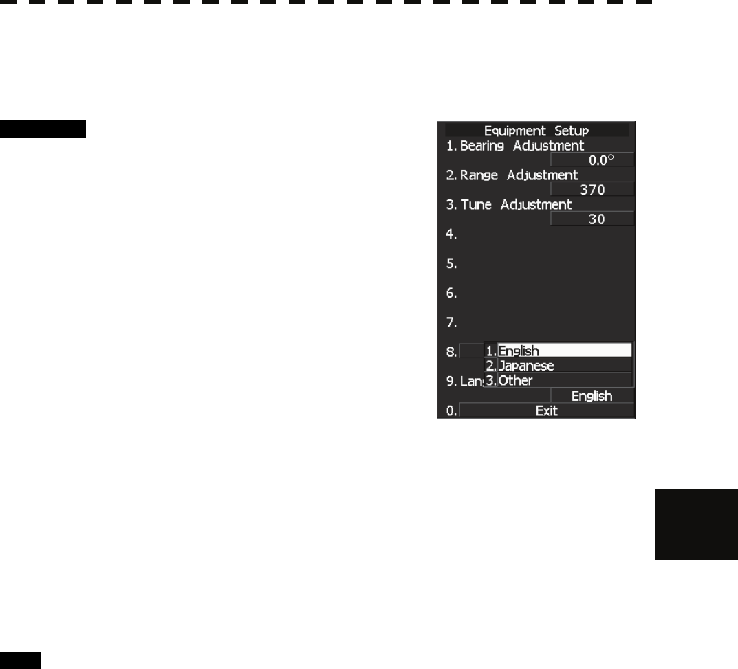
7.3.5 Language Setting (Language)
You can switch between Japanese and English.
Procedure 1 Hold down [RADAR MENU] key.
The Code Input Menu will appear.
2 Press [0] key.
3 Move the cursor onto the “ENT” button
in the Code Input menu, and press
[ENT] key.
The Adjust Menu will appear.
4 Press [1].
The Equipment Setup window will appear.
5 Select the language you want to display,
pressing the numeric keys [1] to [3].
1. English
2. Japanese
3. Other
“Other” in 3. is a language corresponding to characters created in
overseas agents.
To confirm whether or not your language is supported, contact overseas agents or our sales
department.
To make the set language effective, turn off the power supply and then restart.
Exit 1 Press [RADAR MENU] key.
The Main Menu will reappear.
7─37
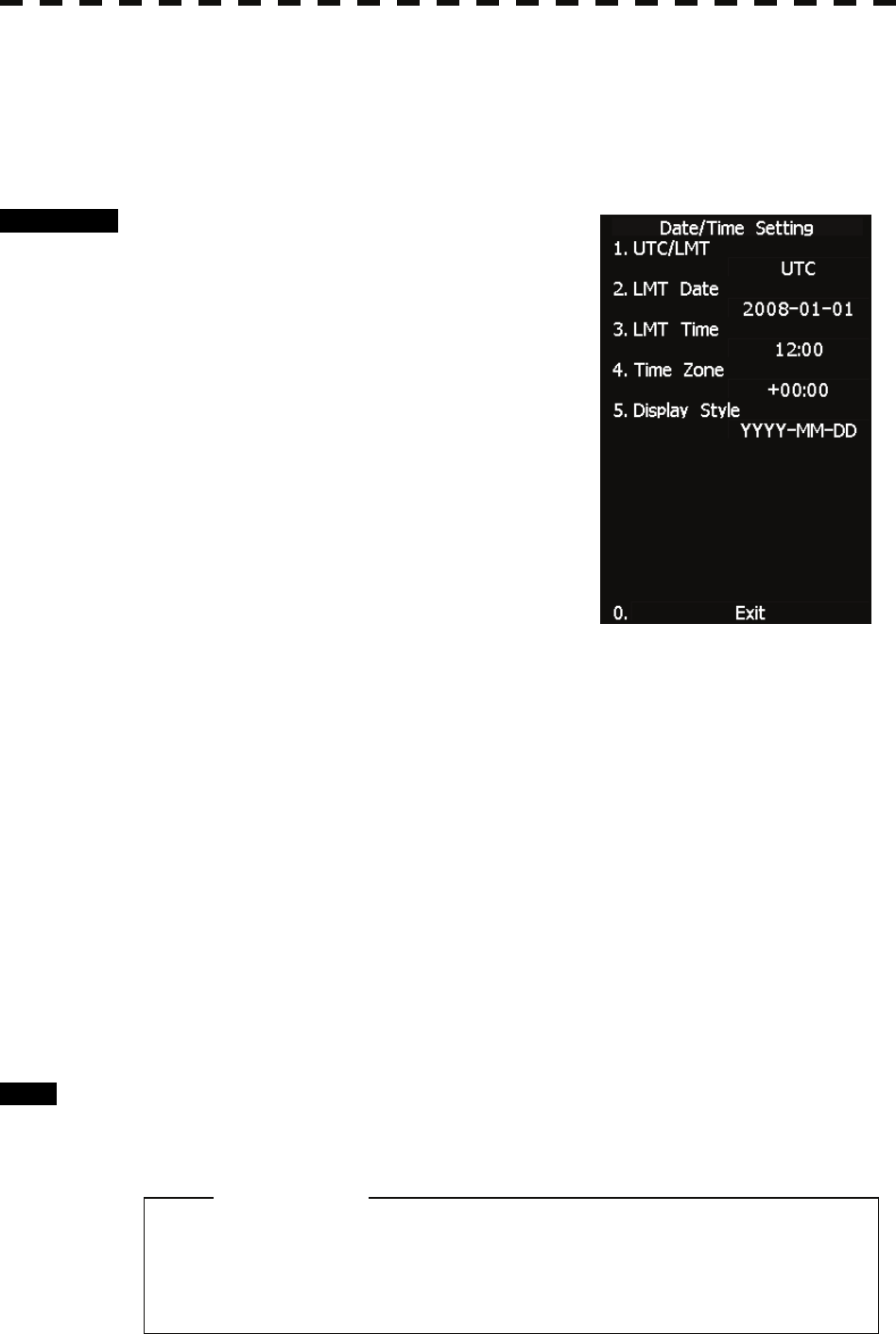
7.3.6 Date/Time Display Setting (Date/Time Setting)
In displaying the time, it is necessary to set the LOCAL TIME, LOCAL DATE and TIME ZONE.
When the “ZDA” sentence of NMEA0183 is received, Date/Time is displayed automatically.
* If “ZDA” sentence is not received, the system internal clock function is used to display the date and time.
Procedure 1 Press [RADAR MENU] key twice.
The RADAR Menu will appear.
2 Open the following windows.
8 Open the Radar Sub Menu window.
4 Open the Data/Time Setting window.
3 Set information about date and time.
[1] UTC/LMT (Time display system)
Press [1] to switch the time mode between:
UTC: Universal Time Coordinate
LMT: Local Time
[2] LMT Date
Input the date in local time.
Press [2] key and call up the numeric
keypad.
Input the date using the numeric keypad or the multi-dial.
Then, press [ENT] button.
[3] LMT Time
Input the time in local time.
Input the time using the numeric keypad or the multi-dial.
Then, press [ENT] button.
[4] Time Zone
Input the time-zone difference between the universal time and local time.
Input the time difference using the numeric keypad or the multi-dial.
Then, press [ENT] button.
[5] Display Style
Set one of the following date display formats.
Press [5] key and select a date display format.
YYYY-MM-DD Example: 2007-12-31
MMM DD, YYYY Example: Dec 31, 2007
DD MMM, YYYY Example: 31 Dec, 2007
Exit 1 Press [RADAR MENU] key.
The menu will be closed.
z The “ZDA” sentence of NMEA0183 take presedence
of the above setting.
Attention
7.4 ADJUSTMENT
7─38
7
yyy
yyyy
CAUTION
7.4 ADJUSTMENT
This section describes the electrical adjustment procedures to be performed by service engineers during system
installation.
Do not carry out the adjustments of the equipment
except authorized service persons. If wrong setting is
carried out, this may cause unstable operation.
Do not carry out the adjustments during navigation.
Otherwise, the radar performance may be affected,
resulting in an accident or trouble.
7─39
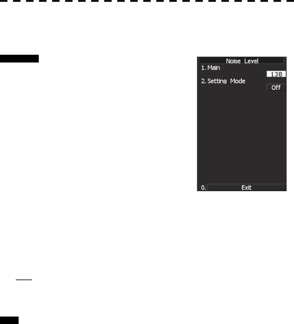
7.4.1 Noise Level Adjustment (Noise Level)
[I] Noise Level Adjustment for Signal Processing
Procedure 1 Hold down [RADAR MENU] key.
The Code Input Menu will appear.
2 Press [0] key.
3 Move the cursor onto the “ENT” button
in the Code Input menu, and press
[ENT] key.
The Adjust Menu will appear.
4 When the Adjust Menu appears, press
[8] key.
The SP/TT INIT Setup Menu will appear.
5 Press [1] key.
The Noise Level Menu will appear.
6 Press [1] key.
The Code Input Menu will open to change the noise level value.
7 Change the value to display echo correctly.
In addition to the entry on the Code Input menu, the Multi-functional Dial Control is
available to change the value.
Note: The noise level is factory-set.
After system installation, a great change in the noise level adjustment value should be avoided; it
should be fine adjusted within ±5.
Exit 1 Press [RADAR MENU] key.
The Main Menu will reappear.
7.4 ADJUSTMENT
7─40
7
yyy
yyyy
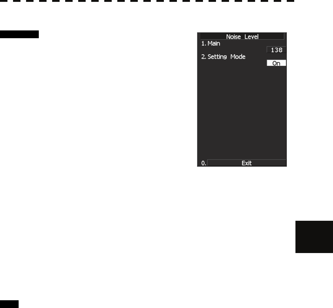
[II] Noise Level Adjustment Mode (Setting Mode)
Procedure 1 Hold down [RADAR MENU] key.
The Code Input Menu will appear.
2 Press [0] key.
3 Move the cursor onto the “ENT” button
in the Code Input menu, and press
[ENT] key.
The Adjust Menu will appear.
4 When the Adjust Menu appears, press
[8] key.
The SP/TT INIT Setup Menu will appear.
5 Press [1] key.
Noise Level Menu will appear.
6 Press [2] key.
The noise level adjustment mode is switched between on and off.
Factory-adjustment method
• The GAIN control is set to the maximum position, the SEA control is set to the
minimum position, the RAIN control is set to the minimum position, and IR,
AUTO-SEA, AUTO-RAIN, PROC, FUNC, and TRAILS are all set to off.
• The noise level adjustment mode is turned on.
• While the noise level adjustment value is decreased gradually, the value with which
radar echoes no longer appear is determined as the set value.
• Ten is added to the set value (with which radar echoes no longer appear), and the result
is set as the final noise level adjustment value.
• The noise level adjustment mode is turned off when the adjustment is finished.
Exit 1 Press [RADAR MENU] key.
The Main Menu will reappear.
7─41
7.4.2 Adjustment of Target Tracking Function (TT)
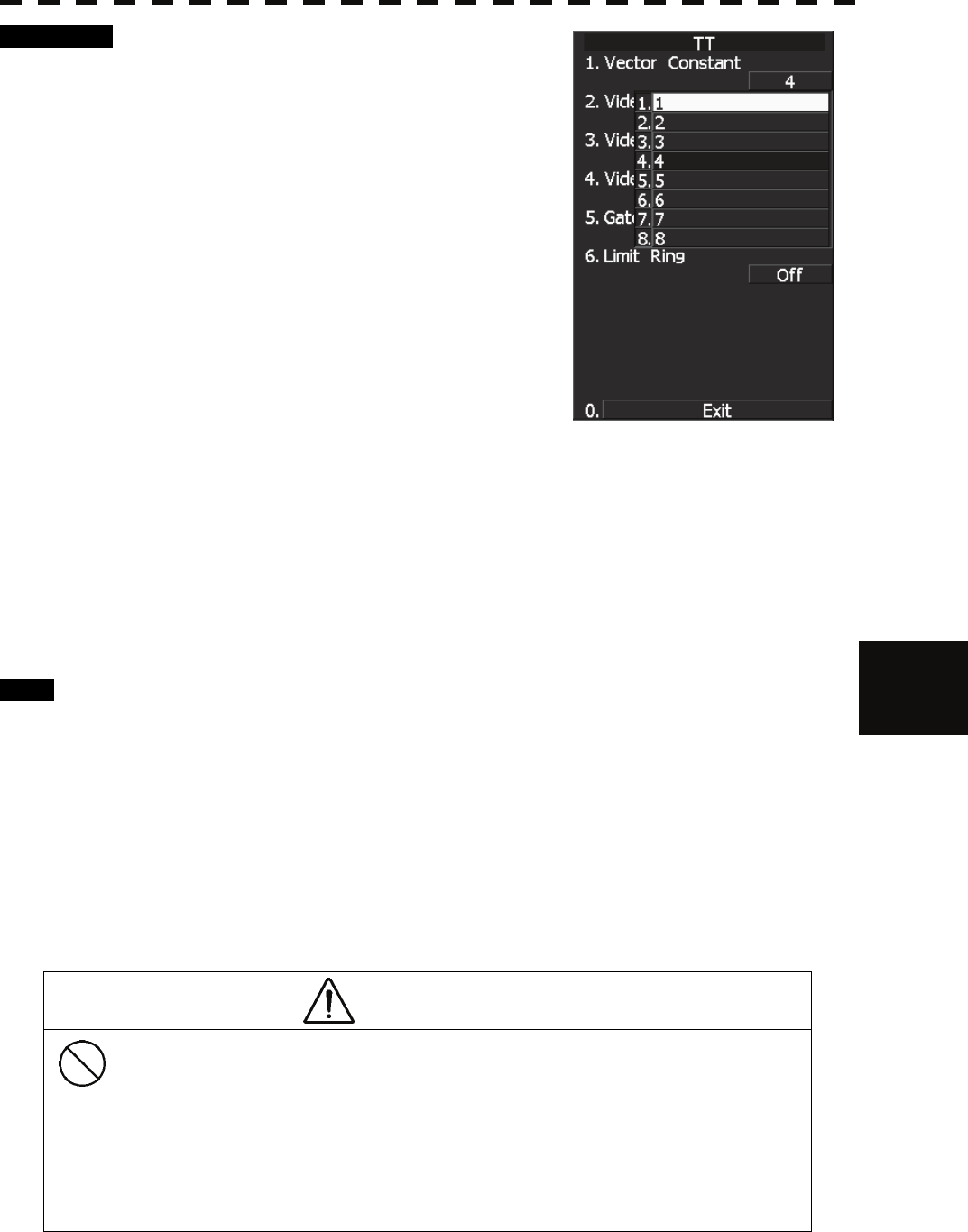
[I] Vector Constant Adjustment (Vector Constant)
Adjust the vector follow-up performance of the target tracking function.
The vector constant is adjusted to an optimal value, so do not change it carelessly.
z Do not change the set value carelessly.
The vector constant shall be set to 4 normally. If the
vector constant value is higher, a target’s vector will
be better followed up when the target and own ship
change their course or speed, but the vector
accuracy will be lower on the contrary.
Attention
CAUTION
Optimal values have been set for Video Level and
Vector Constant; therefore, never change their values
unless absolutely necessary. Failure to comply may
result in accidents that would lower target tracking
performance.
7.4 ADJUSTMENT
7─42
7
yyy
yyyy
Procedure 1 Hold down [RADAR MENU] key.
The Code Input Menu will appear.
2 Press [0] key.
3 Move the cursor onto the “ENT” button
in the Code Input menu, and press
[ENT] key.
The Adjust Menu will appear.
4 Press [8] key while the Adjust Menu is
open.
The SP/TT INIT Setup Menu will appear.
5 Press [2] key.
The TT Menu will appear.
6 Press [1] key.
The window for setting vector constants will appear.
7 Select the value you want to set, pressing the numeric keys [1] to [8].
To improve vector follow-up performance, increase the set value.
To stabilize vectors, decrease the set value.
Exit 1 Press [RADAR MENU] key.
The Main Menu will reappear.
[II] Quantization Level Adjustment (Video Level)
Use the target tracking function (TT) to adjust the level of the signal to be recognized as a target. If a small
value is set, even weak target signals will be input to the target detection circuit of the target tracking function.
However, many unnecessary signals are also input, which may cause unstable target acquisition or tracking. It
is important to set a value four or five greater than the value with which unnecessary signals are detected.
The quantization level is adjusted to an optimal value, so do not change it carelessly.
CAUTION
Do not change the set quantization level carelessly.
If the level deviates from the proper value, the TT
acquisition and tracking functions will deteriorate.
Otherwise, this may cause accidents.
7─43
Procedure 1 Hold down [RADAR MENU] key.
The Code Input Menu will appear.
2 Press [0] key.
3 Move the cursor onto the “ENT” button
in the Code Input menu, and press
[ENT] key.
The Adjust Menu will appear.
4 Press [8] key while the Adjust Menu is
open.
The SP/TT INIT Setup Menu will appear.
5 Press [2] key.
The TT Menu will appear.
• To change the quantization level of the automatic acquisition area
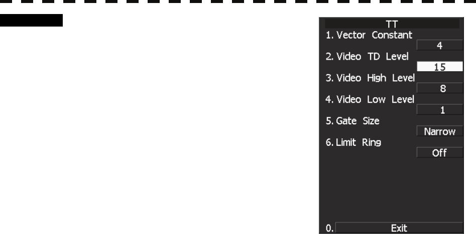
6 Press [2] key.
The numeric keypad for inputting the quantization level of the automatic acquisition area
opens.
7 Enter the Video TD Level value.
The multi-function control can also be used to enter the value.
After having entered the value, move the cursor onto the “ENT” button and press [ENT]
key.
The quantization level can be entered using the numeric keypad, or the multi-function
control knob.
When entry is complete, set the cursor over the "ENT" button on the numeric keypad, and
press [ENT].
You can set this value smaller to detect targets with weaker signals, but by doing so the
unit may pick up unwanted signals that can cause the display of targets to be unstable.
Setting this to a larger value can cause the unit to ignore weaker signals. Filtering out
unwanted signals can stabilize the display of targets, but targets with weaker signals can
be more difficult to detect.
• To change the quantization level of tracking and manual acquisition
6 Press [3] key.
The numeric keypad for inputting the quantization level of tracking and manual
acquisition opens.
7 Enter the Video High Level value.
The multi-function control can also be used to enter the value.
After having entered the value, move the cursor onto the “ENT” button and press [ENT]
key.
7.4 ADJUSTMENT
7─44
7
yyy
yyyy
The quantization level can be entered using the numeric keypad, or the multi-function
control knob.
When entry is complete, set the cursor over the "ENT" button on the numeric keypad, and
press [ENT].
You can set this value smaller to detect targets with weaker signals, but by doing so the
unit may pick up unwanted signals that can cause the display of targets to be unstable.
Setting this to a larger value can cause the unit to ignore weaker signals. Filtering out
unwanted signals can stabilize the display of targets, but targets with weaker signals can
be more difficult to detect.
Exit 1 Press [RADAR MENU] key.
The Main Menu will reappear.
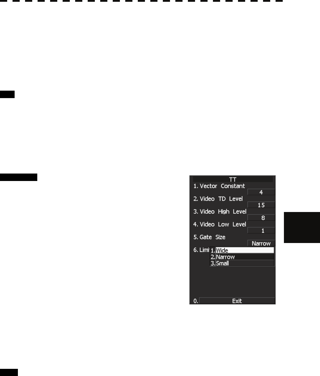
[III] Gate Size Adjustment (Gate Size)
Use the target tracking function (TT) to set a target search area.
The gate size is adjusted to an optimal value, so do not change it carelessly.
Procedure 1 Hold down [RADAR MENU] key.
The Code Input Menu will appear.
2 Press [0] key.
3 Move the cursor onto the “ENT” button
in the Code Input menu, and press
[ENT] key.
The Adjust Menu will appear.
4 Press [8] key while Adjust Menu is
open.
SP/TT INIT Setup menu opens.
5 Press [2] key.
TT menu opens.
6 Press [5] key and select a desired gate size.
Narrow: Small gate size
Normal: Medium gate size
Wide: Large gate size
Exit 1 Press [RADAR MENU] key.
The Main Menu will reappear.
7─45
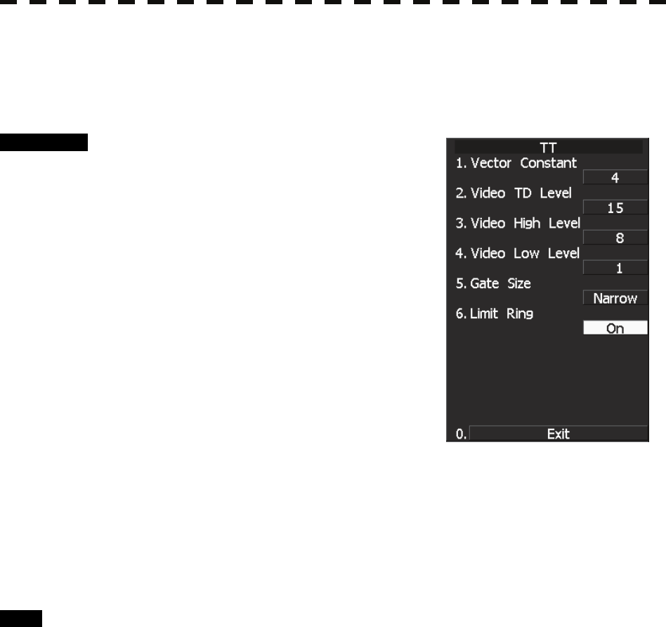
[IV] CPA Limit Ring Display On/Off (Limit Ring)
Use the target tracking function (TT) to determine whether to display the CPA limit for determining a
dangerous ship. When the CPA limit ring display function is turned on and a relative vector is used, the CPA
limit ring is displayed as a circle.
Procedure 1 Hold down [RADAR MENU] key.
The Code Input Menu will appear.
2 Press [0] key.
3 Move the cursor onto the “ENT” button
in the Code Input menu, and press
[ENT] key.
The Adjust Menu will appear.
4 Press [8] key while Adjust Menu is
open.
SP/TT INIT Setup menu opens.
5 Press [2] key.
TT menu opens.
6 Press [6] key.
Activate or deactivate the CPA limit ring display function.
Off: Limit ring not displayed
On: Limit ring displayed
Exit 1 Press [RADAR MENU] key.
The Main Menu will reappear.
7.4 ADJUSTMENT
7─46
7
yyy
yyyy
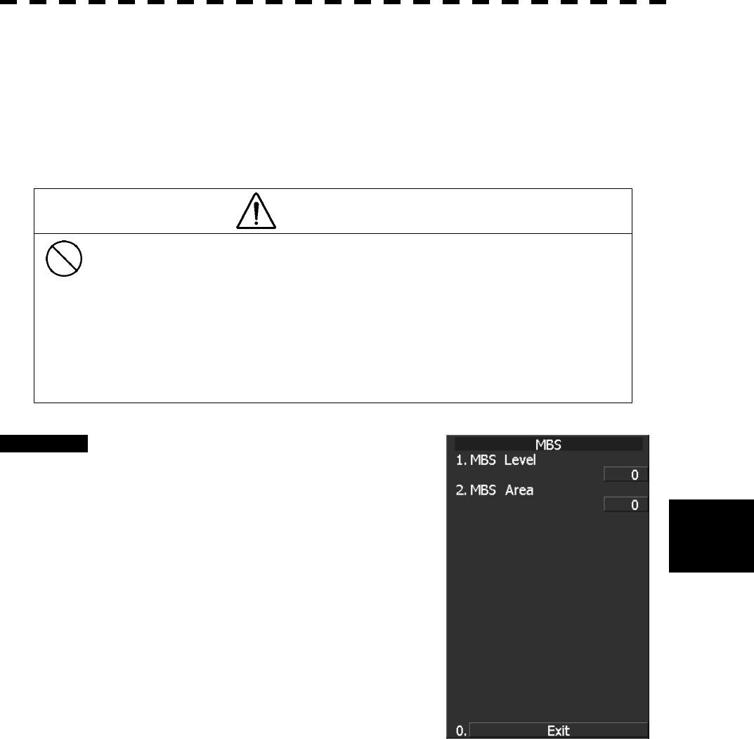
7.4.3 Main Bang Suppression Adjustment (MBS Level)
Main Bang Suppression is adjusted to suppress main bang, a reflection signal from 3D circuit including wave
guide tube, that generally appears as a circular image focusing on the center of the radar display. Optimum
adjustment allows main bang image to remain lightly on the display.
This adjustment is made for settings in the processing circuit of the display unit.
WARNING
Do not change MBS Level/Area unless absolutely
necessary.
Incorrect adjustment may erase targets in point-blank
range and cause collision, resulting in death or serious
injury.
Procedure 1 Perform the following operation before
setting.
• Set the range to 0.125 nm.
• Set the radar video enhance function (ENH).
• Set the correlation processing function
(PROC) to OFF.
• Rotate [AUTO-RAIN] control to the
minimum position (counterclockwise fully).
• Rotate [GAIN/PL] control to the maximum
position (clockwise fully).
• Rotate the [AUTO-SEA] control to achieve
the strength with which main bang can be
judged.
2 Hold down [RADAR MENU] key.
The Code Input Menu will appear.
3 Press [0] key.
4 Move the cursor onto the “ENT” button in the Code Input menu, and
press [ENT] key.
The Adjust Menu will appear.
5 Press [8] key.
The SP/TT INIT Setup Menu will appear.
6 Press [3] key.
The MBS Menu will appear.

7─47
7 Press [2] key.
The numeric keypad to be used in MBS Area Menu will appear.
8 Input “20” as an MBS Area setting value.
The value can also be entered with the multi-dial.
Press [ENT] key after inputting the value.
9 Input [1] key.
The numeric keypad to be used in MBS Level Menu will appear.
10 Input an MBS Level setting value such that the main bang image remains
lightly on the display.
The value can also be entered with the multi-dial.
Press [ENT] key after inputting the value.
11 Press [2] key.
The numeric keypad to be used in MBS Area Menu will appear.
12 Input an MBS area setting value such that the suppression area and the
main bang image completely overlap with each other.
The value can also be entered with the multi-dial.
Press [ENT] key after inputting the value.
Exit 1 Press [RADAR MENU] key.
The Main Menu will reappear.
7.4 ADJUSTMENT
7─48
7
yyy
yyyy
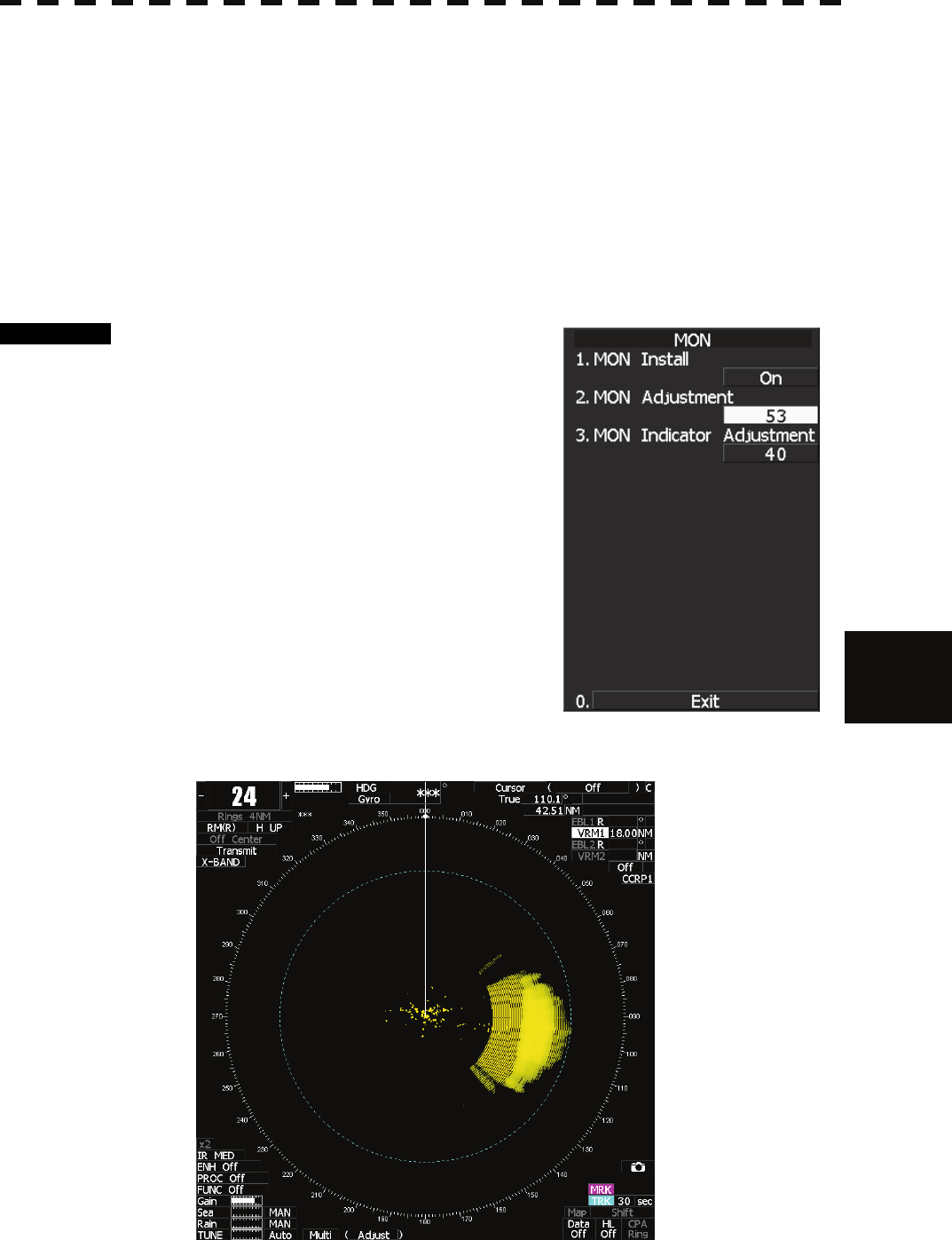
7.4.4 Adjustment of Performance Monitor (NJU-85)
After replacement of either of the following units, adjust the performance monitor according to the procedure in
this section:
• Performance monitor
• Antenna unit
[I] Transmission Monitor Adjustment (MON Adjustment)
Adjust the circuit for monitoring the transmission performance of the radar equipment.
Procedure 1 Hold down [RADAR MENU] key.
The Code Input Menu will appear.
2 Press [0] key.
3 Move the cursor onto the “ENT” button
in the Code Input menu, and press
[ENT] key.
The Adjust Menu will appear.
4 Open Adjust Menu.
4 TXRX Setting
4 MON
2 MON Adjustment
5 Increase or decrease the adjustment
value so that the farthest point of the performance monitor pattern
touches the 18.0 nm line.
7─49
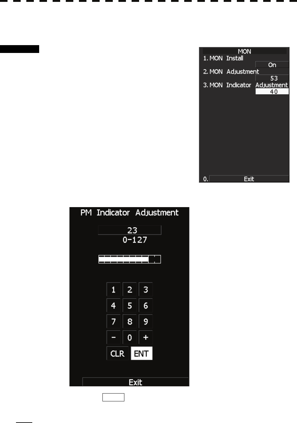
[II] Reception Monitor Adjustment (MON Indicator Adjustment)
Adjust the circuit for monitoring the reception performance of the radar equipment.
Procedure 1 Hold down [RADAR MENU] key.
The Code Input Menu will appear.
2 Press [0] key.
3 Move the cursor onto the “ENT” button
in the Code Input menu, and press
[ENT] key.
The Adjust Menu will appear.
4 Open Adjust Menu.
4 TXRX Setting
4 MON
2 MON Indicator Adjustment
5 Increase or decrease the adjustment
value so that the performance monitor level indicator will be adjusted to
"8."
6 Press the EXIT button to close the adjustment menu.
Note: During performance monitor adjustment, all acquisitions by the target tracking function are released.
The released target acquisitions are not recovered.
7.5 MAINTENANCE MENU
7─50
7
yyy
yyyy
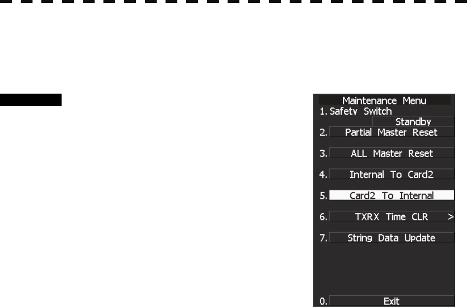
7.5 MAINTENANCE MENU
This item is provided for equipment maintenance, including settings of antenna safety switch, master reset, etc.
CAUTION
Only our service engineers are to make the
adjustment. Neglecting this caution may cause
accidents and failures.
Do not make the adjustments during navigation.
Otherwise, adjustments may affect the radar
functions, causing accidents and failures.
7─51
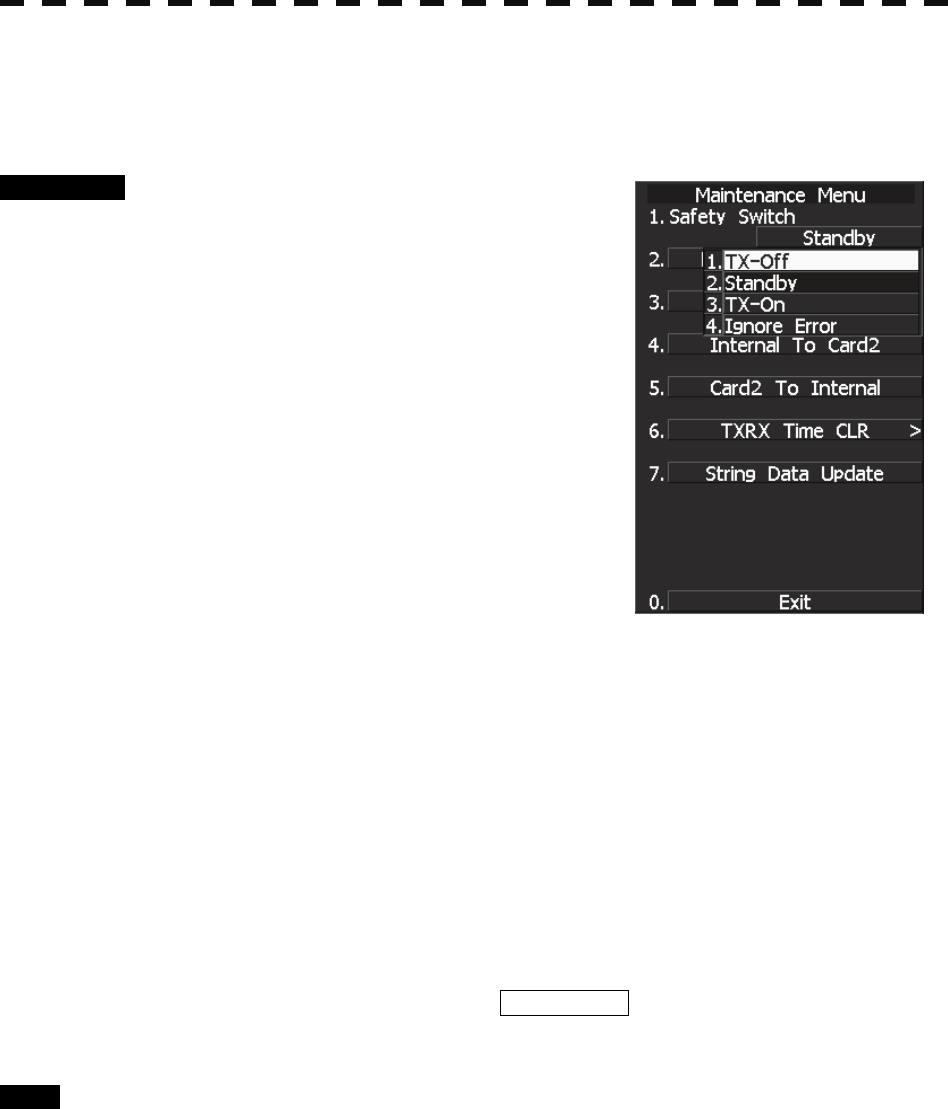
7.5.1 Scanner Safety Switch Setting (Safety Switch)
Use this switch to measure the transmission/reception performance while the antenna is in stopped state.
Procedure 1 Hold down [RADAR MENU] key.
The Code Input Menu will appear.
2 Press [0] key.
3 Move the cursor onto the “ENT” button
in the Code Input menu, and press
[ENT] key.
The Adjust Menu will appear.
4 Press [2] key.
The Maintenance Menu will appear.
5 Press [1] key.
Setting items for the scanner safety switch will
appear.
6 Select the item you want to set, pressing the numeric key [1] to [4].
1. TX OFF:
Stops transmission. (The screen remains in the transmission status.)
2. STANDBY: (Normal setting)
Stops transmission. (The screen switches to the standby status)
3. TX-ON:
Continues transmission without changes. (The display unit remains in transmission
state.)
(However, errors in bearing signals etc. are to occur due to safety switch-off.)
4. IGNORE ERROR:
Continues transmission without changes.(Errors in bearing signals etc. due to safety
switch-off are also ignored.)
7 Change the setting back to 2. Standby when the work is finished.
Exit 1 Press [RADAR MENU] key.
The Main Menu will reappear.
7.5 MAINTENANCE MENU
7─52
7
yyy
yyyy
7.5.2 Initialization of Memory Area (Area Initial)
If system operation is unstable, it may be stabilized by initializing the memory area. To initialize the memory
area, follow the procedure in this section. The memory area is reset to the factory setting when initialized.
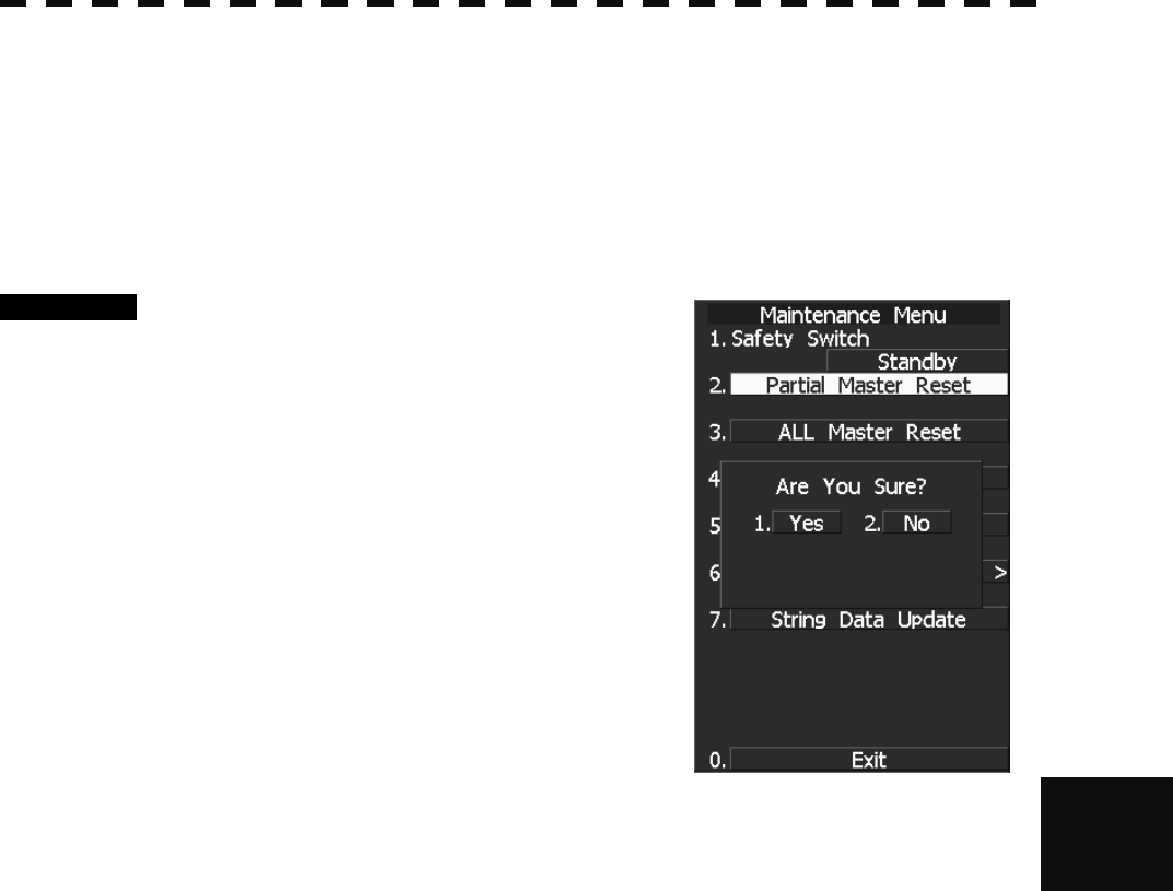
[I] Partial Master Reset
Procedure 1 Hold down [RADAR MENU] key.
The Code Input Menu will appear.
2 Press [0] key.
3 Move the cursor onto the “ENT” button
in the Code Input menu, and press
[ENT] key.
The Adjust Menu will appear.
4 Press [2] key.
The Maintenance Menu will appear.
5 Press [2] key.
The Partial Master Reset Execution Check
window will appear.
1 YES: Execution of Partial Master Reset
2 NO: Cancellation
The memory areas of specified items are initialized, and the system is restarted.
7─53
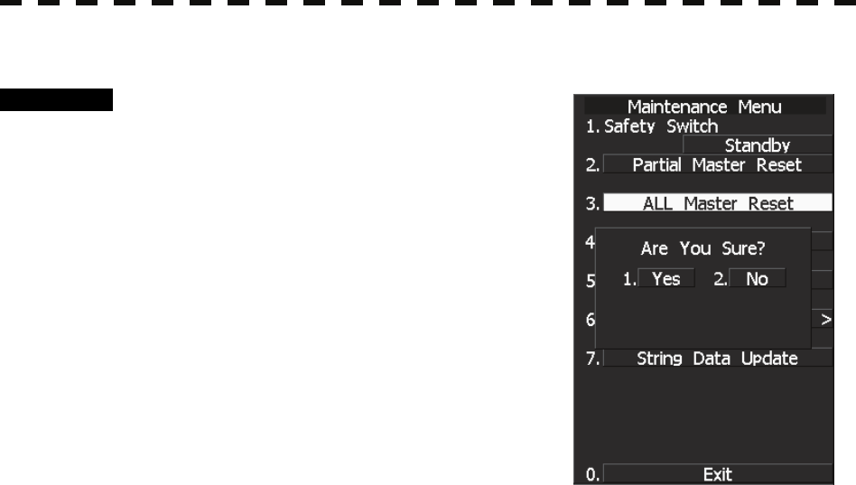
[II] All Master Reset (All Master Reset)
Procedure 1 Hold down [RADAR MENU] key.
The Code Input Menu will appear.
2 Press [0] key.
3 Move the cursor onto the “ENT” button
in the Code Input menu, and press
[ENT] key.
The Adjust Menu will appear.
4 Press [2] key.
The Maintenance Menu will appear.
5 Press [3] key.
The All Master Reset Execution Check window
will appear.
1 YES: Execution of All Master Reset
2 NO: Cancellation
The whole memory area is initialized, and the system is restarted.
7.5 MAINTENANCE MENU
7─54
7
yyy
yyyy
7.5.3 Save of Internal Memory Data (Card2)
The system can save internal memory data such as item settings in menus onto a flash memory card. If the radar
processing circuit in the system has been replaced, the set values before the circuit replacement can be restored
by reading the set values you saved before the replacement.
To save the internal memory data onto a flash memory card (option), the card must be inserted in card slot
beforehand.
The data which are saved : Setting in menus, Trails of own ship (7000 points), Track of other ship (20 target x
1500 points, TT option), user map (256 points), etc.
The data which always changes (for example Radar echo, etc) are not saved.
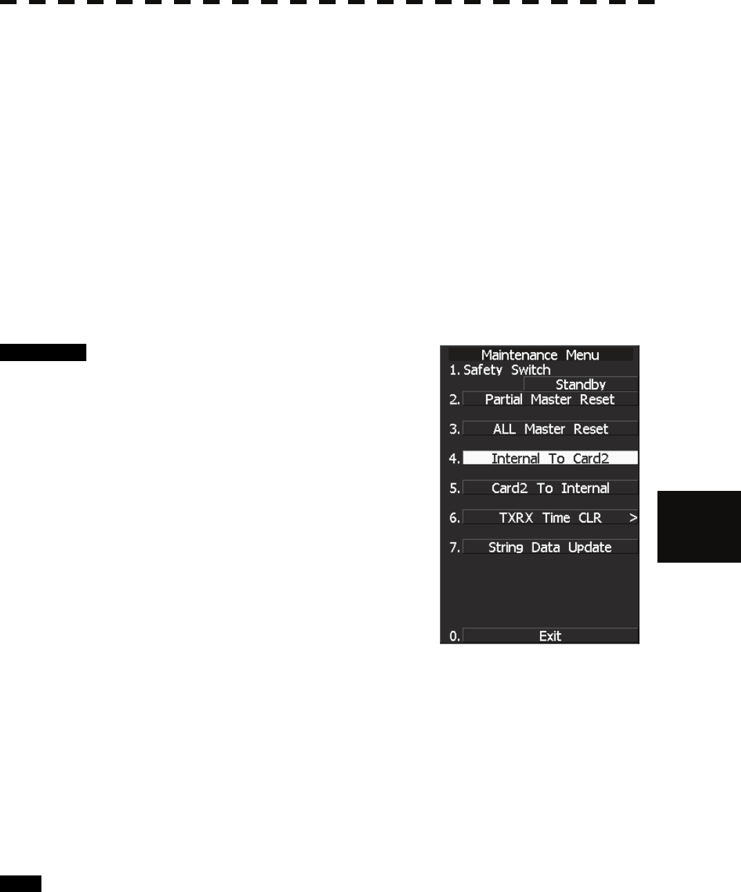
[I] Copying of Internal Settings onto Card (Internal to Card)
Save the internal memory data, such as item settings in menus, onto a flash memory card.
The internal memory data should be saved at completion of system setting, and the operation condition should
be saved periodically.
Procedure 1 Insert a flash memory card into the
CARD slot 2.
The lower slot is slot 1; the upper slot is slot 2.
2 Hold down [RADAR MENU] key.
The Code Input Menu will appear.
3 Press [0] key.
4 Move the cursor onto the “ENT” button
in the Code Input menu, and press
[ENT] key.
The Adjust Menu will appear.
5 Press [2] key.
The Maintenance Menu will appear.
6 Press [4] key.
The execution check window will open to check whether or not you want to copy the
internal settings to Card2.
1 YES: Execution of copy
2 NO: Cancellation
If YES is selected, the internal memory data is saved on the flash memory card.
Exit 1 Press [RADAR MENU] key.
The Main Menu will reappear.
7─55
[II] Reading of Internal Settings from Card (Card to Internal)
Read the saved memory data from the flash memory card into the system memory.
Perform the read operation in order to return the system to the previous operation condition after replacement of
the radar processing circuit in the system.
Procedure 1 Insert the memory flash card, in which
internal settings have been saved, into
Card slot 2.
The lower slot is slot 1; the upper slot is slot 2.
2 Hold down [RADAR MENU] key.
The Code Input Menu will appear.
3 Press [0] key.
4 Move the cursor onto the “ENT” button
in the Code Input menu, and press
[ENT] key.
The Adjust Menu will appear.
5 Press [2] key.
The Maintenance Menu will appear.
6 Press [5] key.
The execution check window will open to check whether or not you want to read the
internal settings from Card2.
1 YES: Read
2 NO: Cancellation
If YES is selected, the memory data is read from the flash memory card into the system
memory.
After the internal memory area is updated, the system is restarted.
7.5 MAINTENANCE MENU
7─56
7
yyy
yyyy
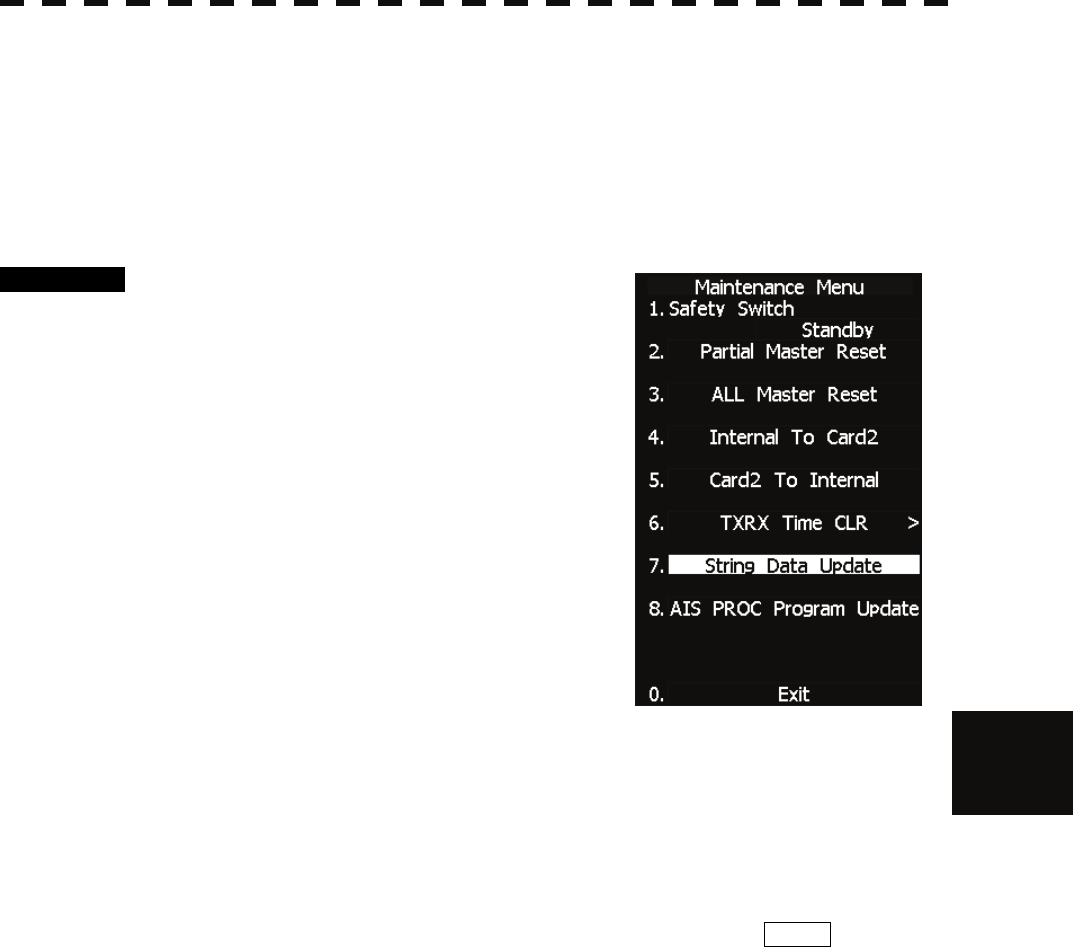
7.5.4 Update of Character String Data (String Data Update)
The system is designed to transfer and display external character strings as the second language display. The
second language is factory-set to "Japanese."
Ask our agent or sales department for the supply of character strings to be updated.
To update character strings, the flash memory card (option) containing the character string file must be inserted
in card slot 2.
Procedure 1 Insert a flash memory card containing
character string data into CARD slot 2.
2 Hold down [RADAR MENU] key.
The Code Input Menu will appear.
3 Press [0] key.
4 Move the cursor onto the “ENT” button
in the Code Input menu, and press
[ENT] key.
The Adjust Menu will appear.
5 Press [2] key.
The Maintenance Menu will appear.
6 Press [7] key.
A dialog appears asking if you wish to load the character string data from Card2.
1 YES : Load data.
2 NO : Cancel.
If YES is selected, the character string file on the flash memory card is read into the
system, and the second language area is updated.
To display the read character strings in the second language, select Other in the menu
shown in Section 7.3.5 “Language Setting (Language)”.
7─57
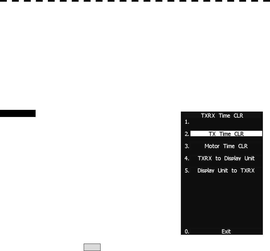
7.5.5 Clear of Antenna Operation Time (TXRX Time CLR)
The system adds up the following operation time and contains it in the antenna unit:
• Transmission time
• Motor run time
Clear the above total time when the magnetron or antenna unit motor is replaced.
[I] Transmission Time Clear (TX Time Clear)
Clear the transmission time of the antenna unit.
Perform the following procedure to clear the transmission time when the magnetron is replaced.
Procedure 1 Hold down [RADAR MENU] key.
The Code Input Menu will appear.
2 Press [0] key.
3 Move the cursor onto the “ENT” button
in the Code Input menu, and press
[ENT] key.
The Adjust Menu will appear.
4 Press [2] key.
The Maintenance Menu will appear.
5 Press [6] key.
Press [2] key.
6. Select Yes in the Transmission Time Clear Confirmation Window.
The transmission time in the antenna's internal control circuit is cleared to 0.
7.5 MAINTENANCE MENU
7─58
7
yyy
yyyy
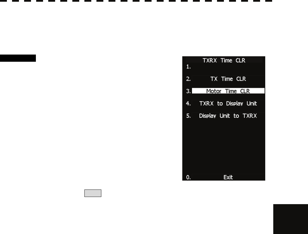
[II] Motor Run Time Clear (Motor Time Clear)
Clear the transmission time of the antenna unit.
Perform the following procedure to clear the transmission time when the magnetron is replaced.
Note: This function can be performed only when the scanner is connected to NKE-2103 and NKE-2254.
Procedure 1 Hold down [RADAR MENU] key.
The Code Input Menu will appear.
2 Press [0] key.
3 Move the cursor onto the “ENT” button
in the Code Input menu, and press
[ENT] key.
The Adjust Menu will appear.
4 Press [2] key.
The Maintenance Menu will appear.
5 Press [6] key.
Press [3] key.
6. Select Yes in the Motor Run Time Clear Confirmation Window.
The motor run time in the antenna's internal control circuit is cleared to 0.
7─59
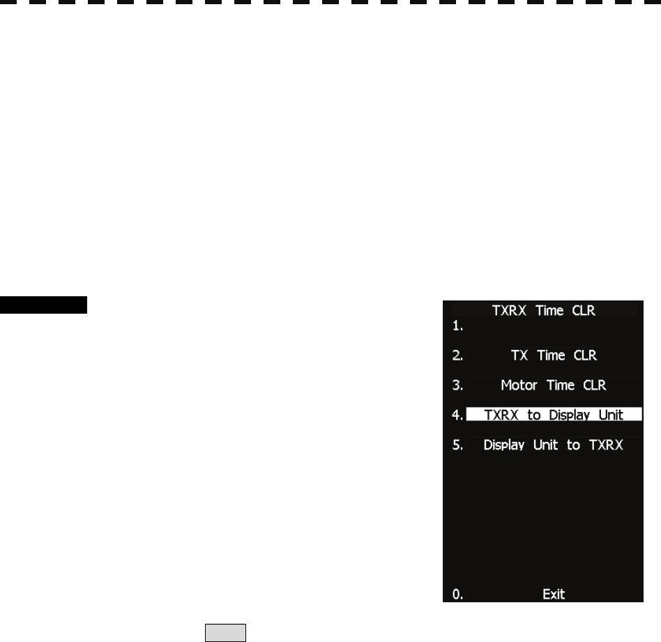
[III] Antenna -> Display Unit (TXRX to Display Unit)
Save the following antenna time data from the antenna unit into the display unit.
• Antenna's operating hours
• Transmission time
• Motor run time
Perform the following procedure to inherit the antenna time data when the antenna's internal control circuit is
replaced.
1. Saving the antenna time data
2. Replacing the antenna's internal control circuit
3. Restoring the antenna time data
Note: This function can be performed only when the scanner is connected to NKE-2103 and NKE-2254.
Procedure 1 Hold down [RADAR MENU] key.
The Code Input Menu will appear.
2 Press [0] key.
3 Move the cursor onto the “ENT” button
in the Code Input menu, and press
[ENT] key.
The Adjust Menu will appear.
4 Press [2] key.
The Maintenance Menu will appear.
5 Press [6] key.
Press [4] key.
6. Select Yes in the Antenna -> Display Unit Confirmation Window.
The antenna time data in the antenna's internal control circuit is saved transferred to the
display unit.
7.5 MAINTENANCE MENU
7─60
7
yyy
yyyy
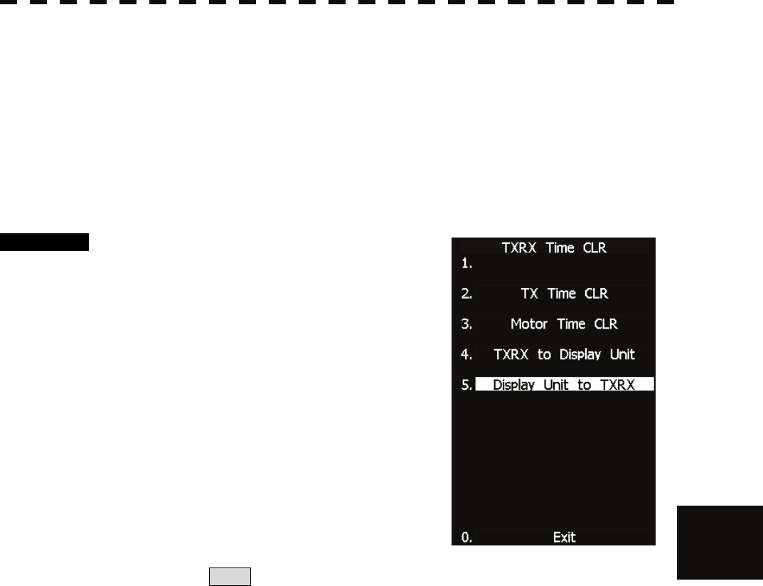
[IV] Display Unit -> Antenna (Display Unit to TXRX)
Restore the antenna time data from the display unit into the antenna's internal control circuit.
Perform the following procedure to inherit the antenna time data when the antenna's internal control circuit is
replaced.
1. Saving the antenna time data
2. Replacing the antenna's internal control circuit
3. Restoring the antenna time data
Note: This function can be performed only when the scanner is connected to NKE-2103 and NKE-2254.
Procedure 1 Hold down [RADAR MENU] key.
The Code Input Menu will appear.
2 Press [0] key.
3 Move the cursor onto the “ENT” button
in the Code Input menu, and press
[ENT] key.
The Adjust Menu will appear.
4 Press [2] key.
The Maintenance Menu will appear.
5 Press [6] key.
Press [4] key.
6. Select Yes in the Display Unit -> Antenna Confirmation Window.
The antenna time data in the display unit is restored transferred to the antenna's internal
control circuit.
7─61
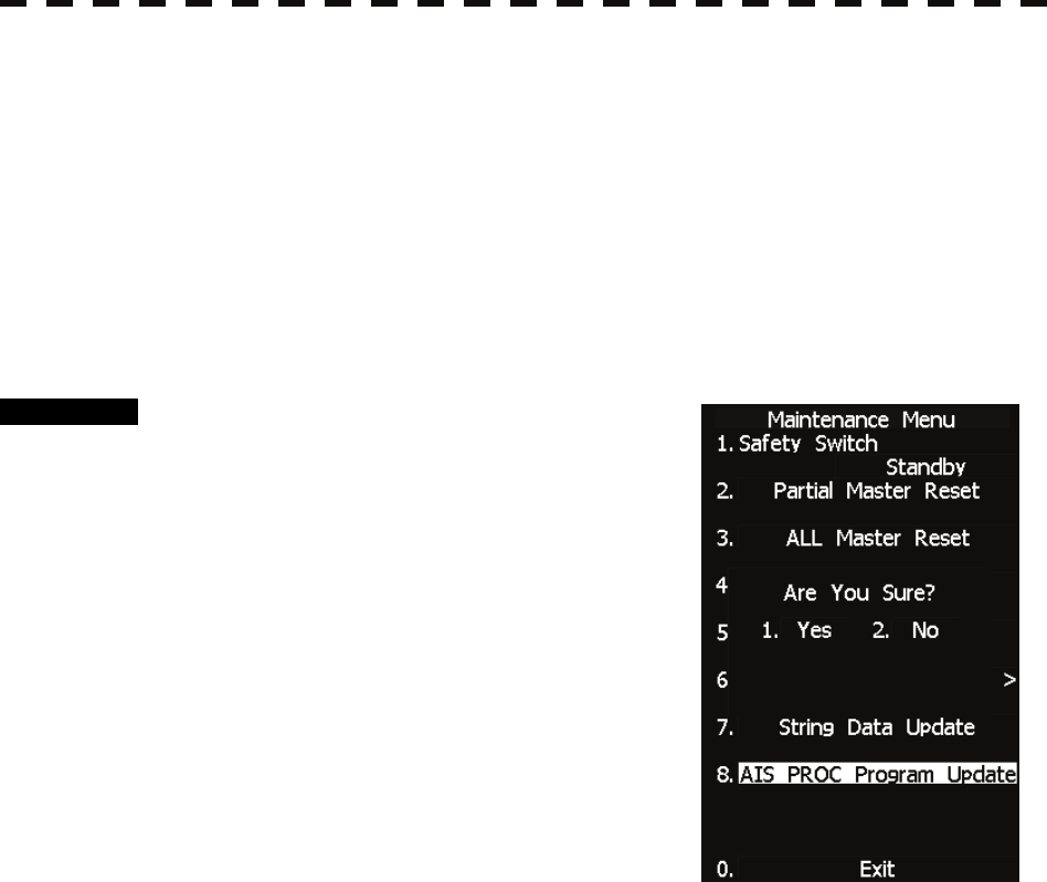
7.5.6 Update of AIS Processor Program (AIS PROC Program Update)
AIS processor programs can be updated by using a flash memory card. In order to update AIS processor
programs, the flash memory card (optional) containing the update program file must be inserted in the card slot
2 beforehand.
[I] Transmission Time Clear (TX Time Clear)
Clear the transmission time of the antenna unit.
Perform the following procedure to clear the transmission time when the magnetron is replaced.
Procedure 1 Insert the flash memory card,
containing the update program file for
AIS processor programs, into the CARD
slot 2.
2 Hold down [RADAR MENU] key.
The Code Input Menu will appear.
3 Press [0] key.
4 Move the cursor onto the “ENT” button
in the Code Input menu, and press
[ENT] key.
The Adjust Menu will appear.
5 Press [2] key.
The Maintenance Menu will appear.
6 Press [6] key.
The window asking whether to update AIS processor programs and whether to execute
character strings will open.
1 YES: Program update execution
2 NO: Program update cancel
When 1. YES is selected:
The AIS processor programs on the flash memory card are updated read into the
equipment.
Follow the displayed instructions during program update.
Do not turn off this equipment during program update.

SECTION 8
MAINTENANCE AND INSPECTION
8.1 ROUTINE MAINTENANCE ................................................. 8-1
8.2 MAINTENANCE ON EACH UNIT........................................ 8-2
8.2.1 Scanner Unit NKE-2062/2103/2254 ............................ 8-2
8.2.2 Display Unit NCD-4380................................................ 8-5
8.3 Performance Check ........................................................... 8-6
8.3.1 Test Menu ..................................................................... 8-7
8.3.1.1 Self-diagnosis function.................................... 8-8
8.3.1.2 Monitor Test..................................................... 8-10
8.3.1.3 Operation Panel Test .......................................8-11
8.3.1.4 MON Display.................................................... 8-13
8.3.1.5 Alarm Logging................................................. 8-14
8.3.1.6 System INFO.................................................... 8-17
8.3.1.7 MAGI................................................................. 8-18
8.3.2 Line Monitor............................................................... 8-19
8.3.3 GPS Reception Status Display (GPS Status).......... 8-21
8.4 REPLACEMENT OF MAJOR PARTS............................... 8-23
8.4.1 Parts Required for Periodic Replacement .............. 8-25
8.4.2 Replacement of magnetron ...................................... 8-25
8.4.3 Motor Replacement ................................................... 8-34
8.4.4 Replacement of Diode Limiter (A303)...................... 8-43
8.4.5 Replacement of Backup Battery .............................. 8-44
8─1
8.1 ROUTINE MAINTENANCE
For operating the radar equipment in the good conditions, it is necessary to make the maintenance work as
described below. If maintenance is made properly, troubles will reduce. It is recommended to make regular
maintenance work.
Common points of maintenance for each unit are as follow:
Clean the equipment.
Remove the dust, dirt, and sea water rest on the equipment cabinet with a piece of dry cloth.
Especially, clean the air vents with a brush for good ventilation.
DANGER
Never carry out internal inspection or repair work of
the equipment by users.
Inspection or repair work by unauthorized personnel
may result in fire hazard or electric shock.
Ask the nearest branch, business office or a dealer for
inspection and repair.
Turn off the main power before maintenance work.
Otherwise, an electric shock may result.
Turn off the main power before cleaning the
equipment. Especially, make sure to turn off the
indicator if a rectifier is used. Otherwise, equipment
failure, or death or serious injury due to electric shock
may result, because voltage is outputted from the
rectifier even when the radar is not operating.
8.2 MAINTENANCE ON EACH UNIT
8─2
8
yyyy
yyyy
8.2 MAINTENANCE ON EACH UNIT
8.2.1 Scanner Unit NKE-2062/2103/2254
After the work, turn "ON" the scanner unit safety switch.
DANGER
When conducting maintenance work on the antenna,
make sure to turn its main power off.
Failure to comply may result in electrocution or
injuries.
Make sure to turn off the antenna operation switch.
Failure to comply may result in injuries caused by
physical contact with the rotating antenna.
Do not touch the radiator. Even if the power is turned
off, the radiator may be rotated by the wind.
8─3
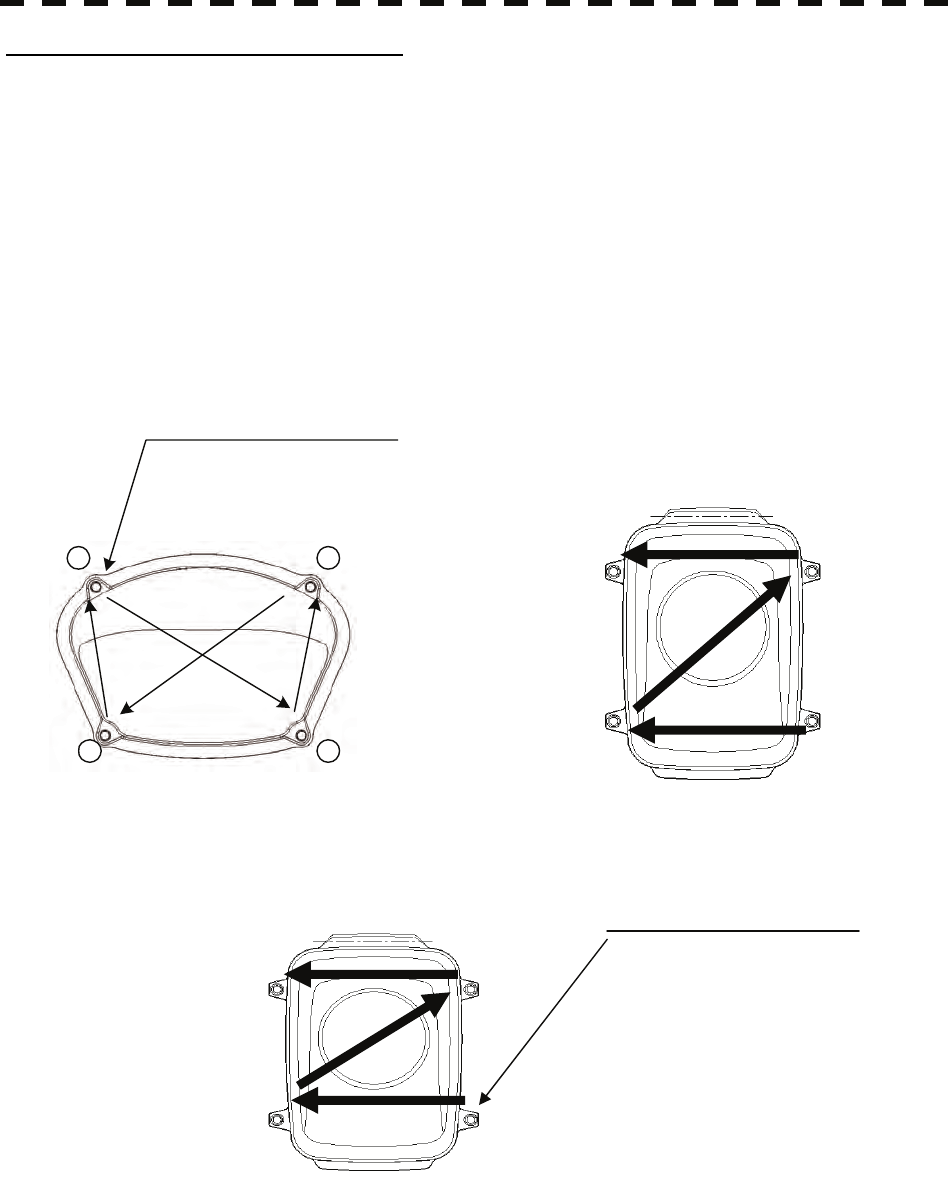
Precautions in Mounting the Cover
When the cover is removed for regular checkup and replacement of parts and refitted after such work, the
procedure of fastening bolts shall be taken with the following precautions:
(a) The proper fastening torque of the fitting bolts (M8) is 1176 to 1470 N•cm (120 to 150kgf•cm) (which
makes the inside water-tight and protects the packings against permanent compressive strain).
The packings start producing from the cover at a torque of approximately 1470N•cm (150kgf•cm).
Do not fasten the bolts with a torque exceeding the specified value. Otherwise, the screws may be broken.
(b) Use an offset wrench of 11 mm × 13 mm or a double-ended wrench of 13 mm × 17 mm (not longer than
200 mm).
(c) Screw all the bolts by hand first to prevent them playing, then fasten them evenly in order not to cause
one-sided fastening. (Fasten the bolts with 25% of the required torque at the first step.)
*: Fasten the bolts in the diagonal order.
④ ③
② ①
Bolt Tightening Procedure of NKE-2103 Cover
4-M8 (stainless steel) bolt
Tightening torque: 120 to 150 kgf/cm
1
2
3
4
4-M8 (stainless steel) bolt
Tightening torque: 120 to 150 kgf/cm
Bolt Tightening Procedure of NKE-2254 Cover
④ ③
② ①
Bolt Tightening Procedure of NKE-2062 Cover

8.2 MAINTENANCE ON EACH UNIT
8─4
8
yyyy
yyyy
(1) Radiator
Check up and clean the radiator.
(2) Rotating section
(a) Supply Oil Seal
An S-band scanner unit without a grease nipple needs grease supply. Remove the cap of the grease
nipple on the front of the radiator support, and supply grease with a grease gun.
Make the oiling every six months. The oil quantity shall be approximately 100 g, which is as much
as the grease comes out of the oil seal. Use the grease of Mobilux 2 of Mobil Oil.
(b) Oiling gears
Apply grease evenly to the tooth surfaces of the main shaft drive gear and the encoder drive gear
with a spreader or brush. Oiling in short intervals is more effective to prevent the gears from wear
and tear and extend their service life, but oil at least every six months.
Use Mobilux2 of Mobile Oil.
(c) Mounting legs
Check the mounting legs and mounting bolts of the scanner unit case for corrosion at intervals and
maintain them to prevent danger. Apply paint to them once a half year because painting is the best
measure against corrosion.
z If the radiator front face (radiation plane) is soiled
with smoke, salt, dust, paint or birds’ droppings,
wipe it with a piece of soft cloth wetted with alcohol
or water and try to keep it clean at all times.
Otherwise, radar beam radiation may attenuate or
reflect on it, resulting in deterioration of radar
performance.
z Never use solvents of gasoline, benzine,
trichloroethylene and ketone for cleaning.
Attention
8─5
8.2.2 Display Unit NCD-4380
Dust accumulated on the screen will reduce clarity and darken the video. For cleaning it, wipe it with a piece of
soft cloth (flannel or cotton). Do not wipe it strongly with a piece of dry cloth nor use gasoline or thinner.
WARNING
When cleaning the screen, do not wipe it too strongly
with a dry cloth. Also, do not use gasoline or thinner
to clean the screen. Otherwise the screen surface may
be damaged.

8.3 PERFORMANCE CHECK
8─6
8
yyyy
yyyy
8.3 PERFORMANCE CHECK
Make operational check on the radar equipment regularly and if any problem is found, investigate it
immediately. Pay special attention to the high voltage sections in checking and take full care that no trouble is
caused by any error or carelessness in measurement. Take note of the results of checking, which can be used
effectively in the next check work.
Operational check shall be made in accordance with Table 8-1 Function Check List in the order as specified in
it.
Table 8-1 Check List
Equipment Item to be checked Criteria Remarks
Transmitter-receiver
Unit Tuning LED of Receiver The LED is lighting during
operation 48NM range
Video and echoes on the screen
Sensitivity
LCD brilliance can be controlled
correctly
Various markers
Various numerical indications
Lighting
Can be correctly controlled
Safety Switch
Various Currents and Voltages Refer to [II] in Section 8.3.1.1
Communications Lines Refer to [III] in Section 8.3.1.1
Memory Refer to [I] in Section 8.3.1.1
Panel Refer to Section 8.3.1.3
Monitor Refer to Section 8.3.1.2
TT Refer to Section 5.2.7
Magnetron current Refer to Section 8.3.1.7
Performance Monitor Refer to Section 8.3.1.4
Error Logging Display Refer to Section 8.3.1.5
Display Unit
System Information Display Refer to Section 8.3.1.6
8─7
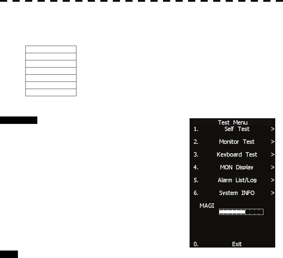
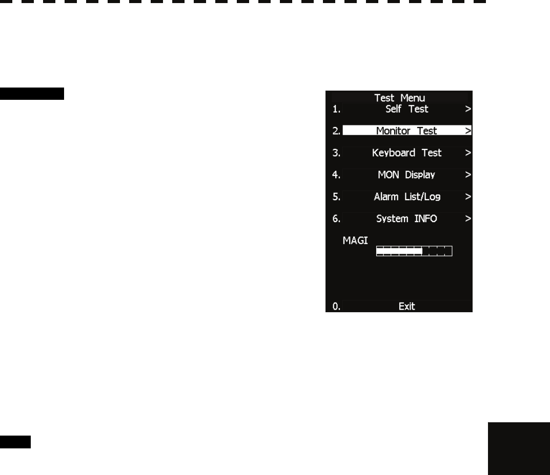
8.3.1 Test Menu
The performance status of this radar equipment can be checked on the TEST Menu.
Self Test [I] Self-diagnostic function
Monitor Test [II] Monitor check
Keyboard Test [III] Operation panel check
MON Display [IV] Performance monitor
Error Logging [V] Error log display
System INFO [VI] System information display
MAGI
[VII] Indication of magnetron current
* Execution of MON Display requires a performance monitor unit NJU-85.
Procedure 1 Press [RADAR MENU] key twice.
Press [8] key.
Press [9] key.
The TEST Menu will appear.
* Software button ⑥ located at the operation/message area in
Section 2.3.9 is also available.
2 Select the check item you want to
check, pressing the numeric keys [1] to
[6] on Test Menu.
The list of check items will appear.
Exit 1 Press [RADAR MENU] key.
The TEST Menu will be closed.
8.3 PERFORMANCE CHECK
8─8
8
yyyy
yyyy
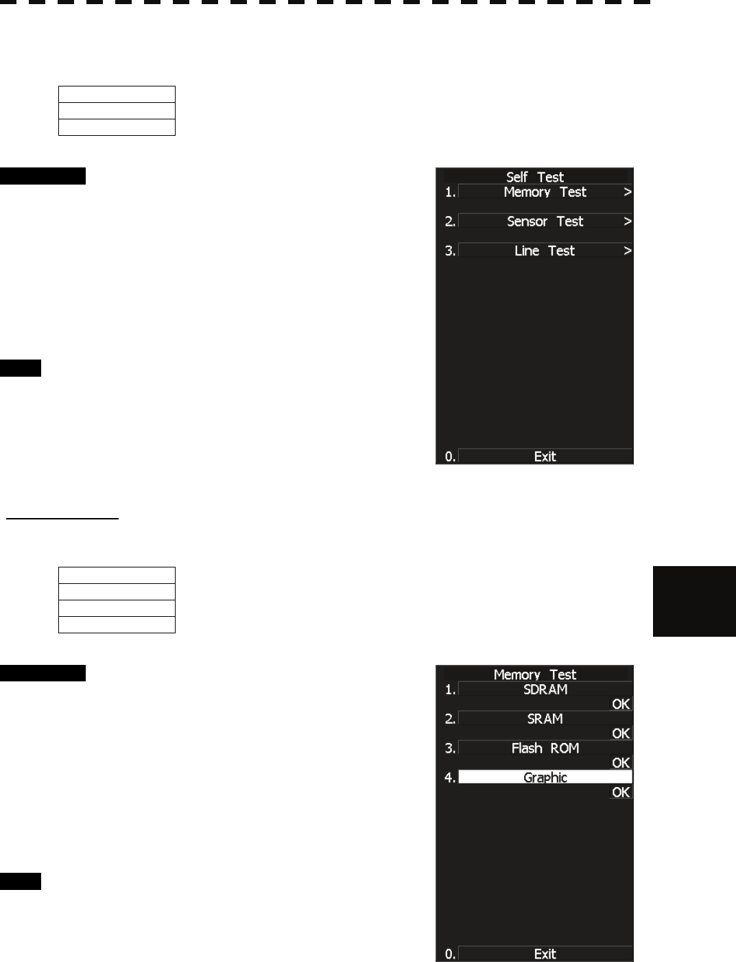
8.3.1.1 Self-diagnosis function
Check of Memory, Scanner Unit, and Communications Lines
Memory Test 1) Memory check
Sensor Test 2) Antenna check
Line Test
3) Communication line check
Procedure 1 Press [1] key while the Test Menu is
open.
The SELF TEST Menu will appear.
2 Select the item you want to check,
pressing numeric keys [1] to [3] .
The SELF CHECK Menu will appear.
Exit 1 Press [RADAR MENU] key.
The Self Test Menu will be closed.
[I] Memory Test
Checks for the performance of built-in memory.
SDRAM SDRAM check
SRAM SRAM check
FLASH ROM Flash ROM check
GRAPHIC
Graphic check
Procedure 1 Press [1] key while the Self Test menu
is open.
The Memory Test Menu will appear.
2 Select the item you want to check,
pressing numeric keys [1] to [4].
When no abnormality is found, OK is displayed.
When an abnormality is found, NG is displayed.
Exit 1 Press [RADAR MENU] key.
The menu will be closed.
8─9
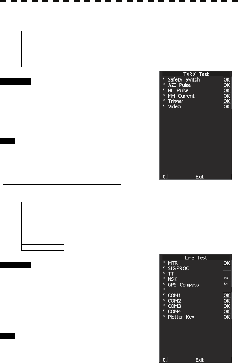
[II] Sensor Test
Checks for signals from the antenna.
Safety Switch Antenna’s safety switch check
AZI Pulse Antenna rotation signal check
HL Pulse Heading line signal check
MH Current Check on the load current of high voltage in the modulator
Trigger Radar trigger signal check
Video
Radar video check
Procedure 1 Press [2] key while the Self Test menu
is open.
The Sensor Test menu will appear.
When no abnormality is found, OK is displayed.
When an abnormality is found, NG is displayed.
In standby, ** will appear.
Exit 1 Press [RADAR MENU] key.
The menu will be closed.
[III] Check of Communication Lines (Line Test)
Check communication with operational devices and external navigators.
MTR Check on connection with the transmitter-receiver
NSK Check on connection with the NSK unit
GPS Compass Check on connection with the GPS compass
COM1 Check on connection with COM1
COM2 Check on connection with COM2
COM3 Check on connection with COM3
COM4 Check on connection with COM4
Plotter Key
Check on connection with Plotter Key.
Procedure 1 Press [3] key with the Self Test menu
open.
The Line Test menu will appear.
When no abnormality is found, OK is displayed.
When an abnormality is found, NG is displayed.
The status display field of equipment not
connected is **.
Exit 1 Press [RADAR MENU] key.
The menu will be closed.
8.3 PERFORMANCE CHECK
8─10
8
yyyy
yyyy
8.3.1.2 Monitor Test
Checks for the display.
The test pattern will be shown on the display.
Procedure 1 Press [2] key while the Test Menu is
open.
The Monitor Test Menu will appear.
2 Select the item number you want to
display, pressing numeric keys [1] to [5]
of the test pattern.
The selected test pattern will be displayed.
Pattern 1: All colors are filled with white.
Pattern 2: A white box is displayed on the black background of
1024 × 768 dots.
Pattern 3: Displays rectangle × 2, circle × 2, and cross-shape× 13
(white lines on the black background).
Pattern 4: Displays “H” of 9 dots × 9 dots on the entire screen
(white character on the black background).
Pattern 5: Gray scale display (16 levels)
Pattern 6: Displays a color bar.
Pattern 7: The square figure of a specified RGB value is shown at the center of the display.
3 To return to the original display, press any key.
If Pattern7 is selected, resetting is performed by pressing the CLR
button.
If errors occur in the monitor, no test pattern will appear.
Exit 1 Press [RADAR MENU] key.
The menu will be closed.
8─11
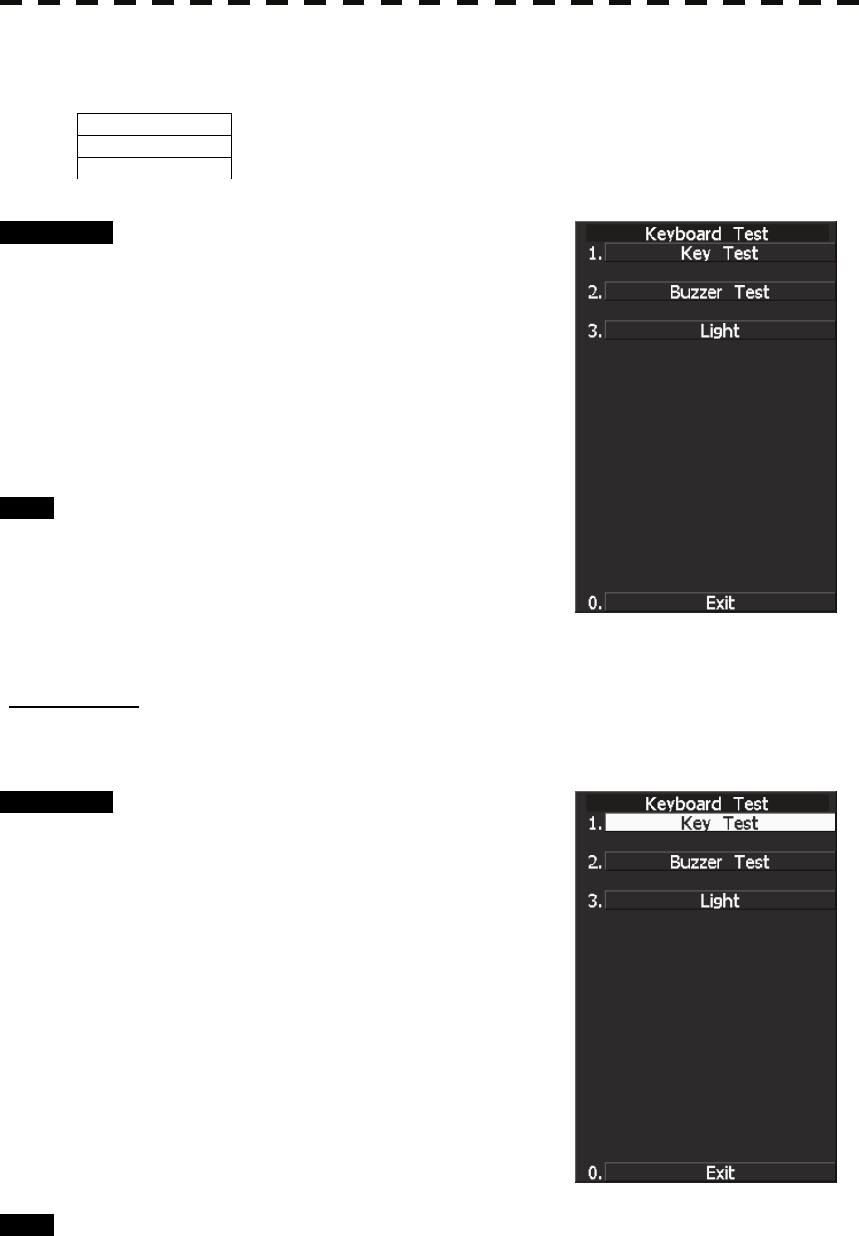
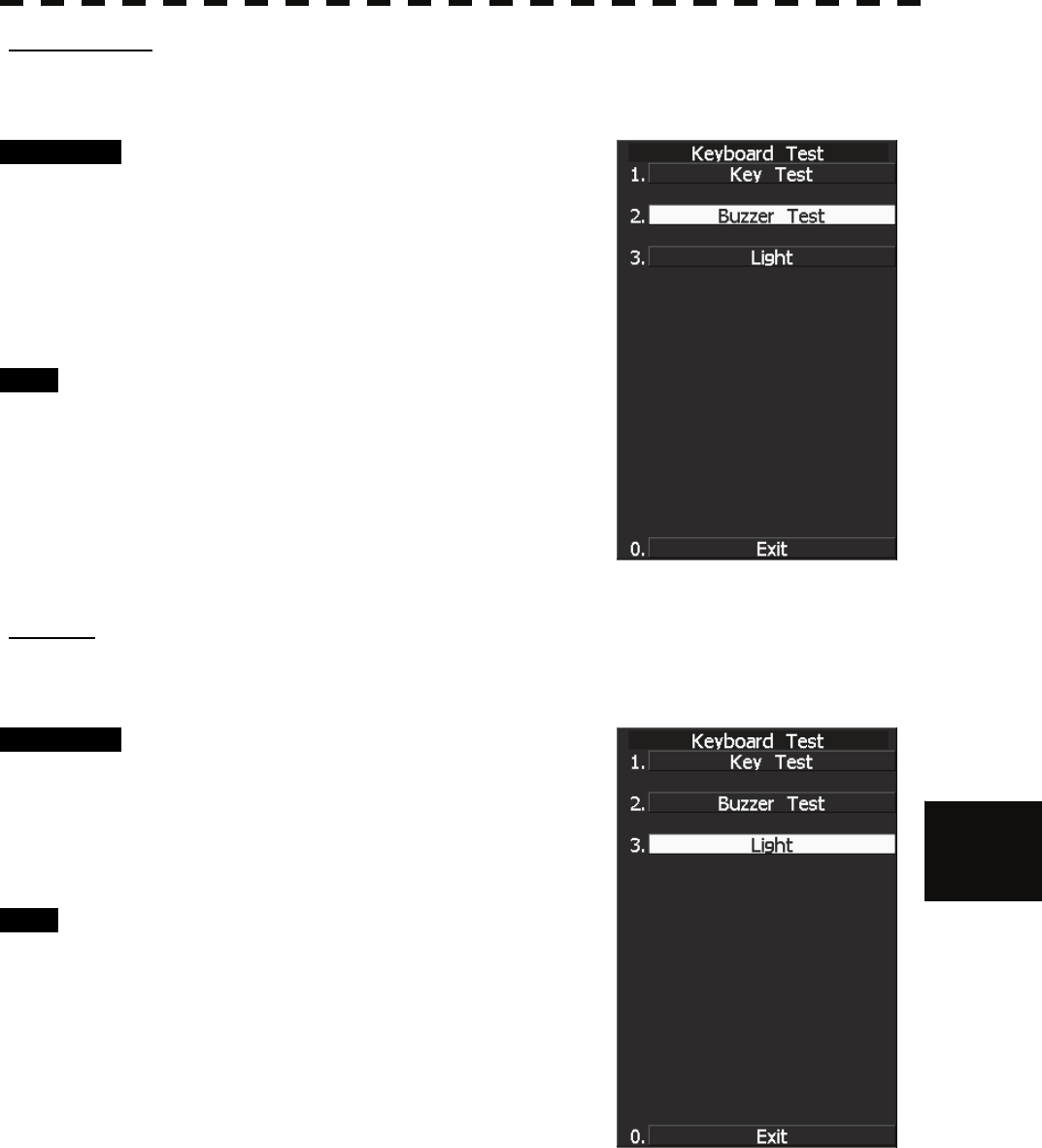
8.3.1.3 Operation Panel Test
Checks for the controls and switches of the operation panel.
Key Test 1) Key check
Buzzer Test 2) Buzzer check
Light
3) Keyboard light check
Procedure 1 Press [3] key while the Test Menu is
open.
The Keyboard Test Menu will appear.
2 Select the item number you want to
check, pressing numeric keys [1] to [3]
of the item.
The check contents will be displayed.
Exit 1 Press [RADAR MENU] key.
The menu will be closed.
[I] Key Check
Checks for the controls and switches of the operation panel.
Procedure 1 Press [1] key while the Keyboard Test
menu is open.
The operation panel image will appear at the
upper left of the display.
Each key on the operation panel on the display is
shown in reverse video at the same time the key
is pressed, and the name of the pressed key is
displayed.
2 To perform resetting, position the
cursor to "EXIT" shown on the left side
of the display, and press the [ENT] key
or [0] key.
Exit 1 Press [0] key.
The menu will be closed.
8.3 PERFORMANCE CHECK
8─12
8
yyyy
yyyy
[II] Buzzer Test
Checks for the operation panel buzzer.
Procedure 1 Press [2] key while the Keyboard Test
menu is open.
The buzzer will sound.
2 The buzzer automatically stops after it
sounds for a specified length of time.
Exit 1 Press [RADAR MENU] key.
The menu will be closed.
[III] Light
Checks for the operation panel light.
Procedure 1 Press [3] key while the Keyboard Test
menu is open.
The brightness of the operation panel is
gradually intensified at four levels.
Exit 1 Press [RADAR MENU] key.
The menu will be closed.
8─13
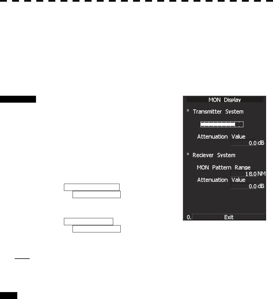
8.3.1.4 MON Display
The performance monitor status is shown.
* A performance monitor unit is required.
Transmitter System Check attenuation in the transmitter system
Attenuation Value
Receiver System Check attenuation in the receiver system
MON Pattern Range
Attenuation Value
Procedure 1 Press [4] key while Test Menu is open.
MON Display menu opens.
2 Turn [VRM] control to slide the VRM to
the end of the performance monitor
pattern.
Attenuation in the receiver system is displayed in
Attenuation Value of Receiver System.
3 Check the attenuation value.
* Transmitter System
Attenuation Value
Normal operating range :
-7.0dB<indication value<+2.0dB
* Receiver System
Attenuation Value
Normal operating range :
-3.0dB<indication value<+3.5dB
Note: If Receiver System Attenuation Value display is under -3 dB or Transmitter System Attenuation Value
display is under -7 dB with the the performance monitor test, radar should be checked by service
engineer. This means that the TX/RX unit may be faulty. Consult with the near-by dealer or our
sales department.
Exit 1 Press [RADAR MENU] key.
The menu will be closed.
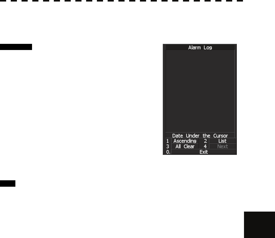
8.3 PERFORMANCE CHECK
8─14
8
yyyy
yyyy
8.3.1.5 Alarm Logging
Displays previously occurred system errors with the dates and times when they occurred.
The current error is displayed in reverse video.
Procedure 1 Press [5] key while the Test Menu is
open.
The Alarm Log will appear.
2 Error logs will be displayed.
For the display contents, refer to Table 8-2, Table
8-3 and Table 8-4.
Press [1] key to switch the error log display
modes between chronological display and
reverse chronological display.
Press [2] key to switch between error log display
and alarm list display.
Press [3] key to delete all error logs.
Press [4] key to see the next page.
Place the cursor over the listed error to see when
it occurred.
Exit 1 Press [RADAR MENU] key.
The menu will be closed.

8─15
Table 8-2 System alarm warning list 1: Scanner
Message Class Description ALR No.
TXRX(AZI) Alarm Scanner: Rotation signal (BP) error. 311
TXRX(Data) Alarm Scanner: Communication data error, checksum error or data mismatched. 901
TXRX(Fan 1) Alarm Scanner: FAN 1 error. 320
TXRX(Fan 2) Alarm Scanner: FAN 2 error. 902
TXRX(Heater) Alarm Scanner: Magnetron heater voltage error. 314
TXRX(HL) Alarm Scanner: Reference rotation signal (HL) error. 312
TXRX(MHV) Alarm Scanner: Modulator's high voltage alarm. 315
TXRX(Motor) Alarm Scanner: Motor current error. 317
TXRX(Reverse) Alarm Scanner: Reverse rotation. 313
TXRX(SSW Off) Alarm Scanner: Safety switch OFF. 308
TXRX(Time Out) Alarm Scanner: No communication. 326
TXRX(Trigger) Alarm Scanner: TRIGGER error. 310
TXRX(Video) Alarm Scanner: VIDEO error. 309
ALR No: Unique alarm number in ALR sentence and ACK sentence.
Table 8-3 System alarm warning list 2: Display
Message Class Description ALR No.
AIS PROC(Data) Alarm AIS processing circuit: Communication data error or checksum error. 919
AIS PROC(Time Out) Alarm AIS processing circuit: No communication. 328
Indicator(Fan) Alarm LCD monitor: FAN error. 905
Keyboard(Data) Alarm Operation unit: Communication data error, checksum error or data
mismatched. 906
Keyboard(Time Out) Alarm Operation unit: No communication. 325
Keyboard2(Data) Alarm Second operation unit: Communication data error, checksum error or
data mismatched. 908
Keyboard2(Time Out) Alarm Second operation unit: No communication. 907
PROC(AZI) Alarm Process unit: Rotation signal error. 305
PROC(HL) Alarm Process unit: Reference rotation signal error. 306
PROC(Interrupt) Alarm Process unit: Interrupt error. 913
PROC(Reverse) Alarm Process unit: Reverse rotation error. 307
PROC(Trigger) Alarm Process unit: Trigger error. 304
PROC(Video) Alarm Process unit: VIDEO error. 303
ALR No: Unique alarm number in ALR sentence and ACK sentence.
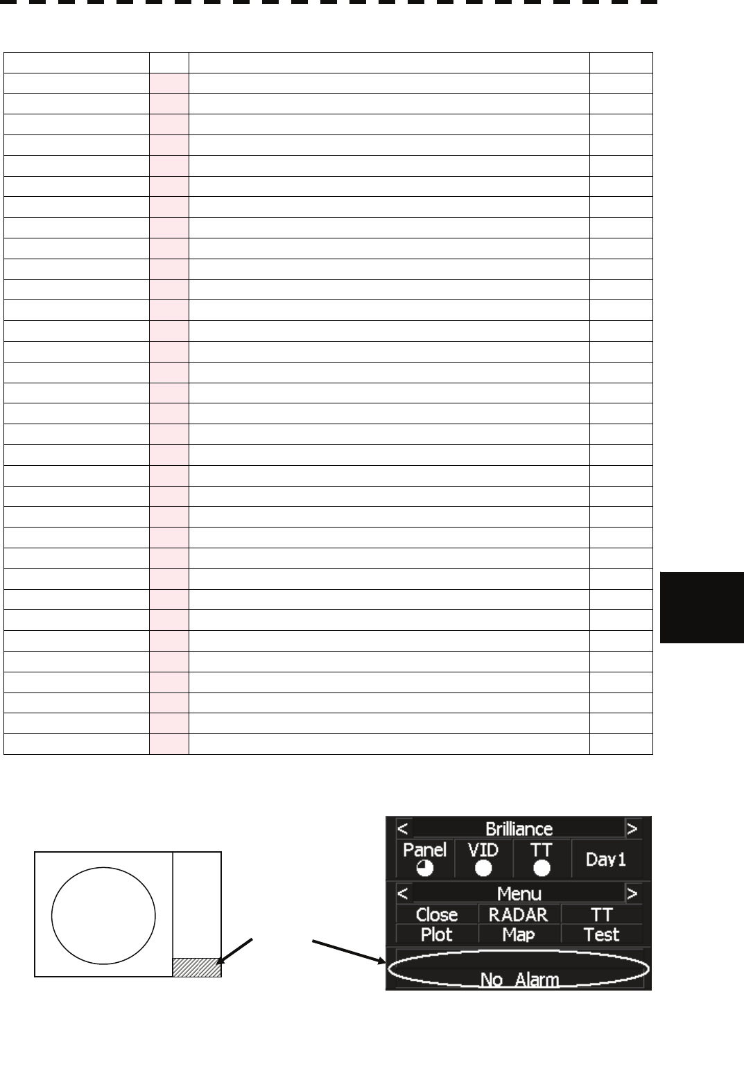
8.3 PERFORMANCE CHECK
8─16
8
yyyy
yyyy
Table 8-4 System alarm warning list 3: External device communication
Message Class Description ALR No.
2AXG(Data) Alarm 2AXG: Communication data error. 911
2AXG(Time out) Alarm 2AXG: No communication. 342
2AXW(Data) Alarm 2AXW: Communication data error. 910
2AXW(Time out) Alarm 2AXW: No communication. 341
AIS(Alarm ***) Alarm AIS alarm and the alarm number.
AIS(Data) Alarm AIS: Communication data error or checksum error. 918
AIS(Time Out) Alarm AIS: No communication. 116
Autopilot(Data) Alarm Autopilot: Communication data error or checksum error. 930
Autopilot(Time Out) Alarm Autopilot: No communication. 101
COM Port1(Open) Alarm COM1: Port error. 920
COM Port2(Open) Alarm COM2: Port error. 921
COM Port3(Open) Alarm COM3: Port error. 922
COM Port4(Open) Alarm COM4: Port error. 923
Current(Data) Alarm Tidal current: Communication data error or checksum error. 927
Current(Time Out) Alarm Tidal current: No communication. 119
Depth(Data) Alarm Water depth: Communication data error or checksum error. 924
Depth(Time Out) Alarm Water depth: No communication. 115
GPS(Date) Alarm Valid date data from GPS not receive. 112
GPS(Datum) Alarm Valid geodetic system data from GPS not receive. 122
GPS(Position) Alarm Valid latitude and longitude data from GPS not receive. 102
GPS(Speed) Alarm Valid speed data from GPS not receive. 343
Heading(Time Out) Alarm Heading data: No communication. 113
L/L(Out of Bounds) Alarm L/L Own ship's latitude is over 85°N or 85°S. 123
Log(Data) Alarm Log: Communication data error (error bit detected). 111
NSK(Time Out) Alarm NSK unit: No communication. 324
Rate of Turn(Data) Alarm Rate of Turn: Communication data error or checksum error. 928
Rate of Turn(Time Out) Alarm Rate of Turn: No communication. 120
Rudder(Data) Alarm Rudder Sensor Angle: Communication data error or checksum error. 929
Rudder(Time Out) Alarm Rudder Sensor Angle: No communication. 121
Temperature(Data) Alarm Water temperature: Communication data error or checksum error. 925
Temperature(Time Out) Alarm Water temperature: No communicaton. 117
Wind(Data) Alarm Wind direction/velocity: Communication data error or checksum error. 926
Wind(Time Out) Alarm Wind direction/velocity: No communication. 118
ALR No: Unique alarm number in ALR sentence and ACK sentence.
Reference: Alarm message is displayed in the lower right of the display.
Position of alarm message
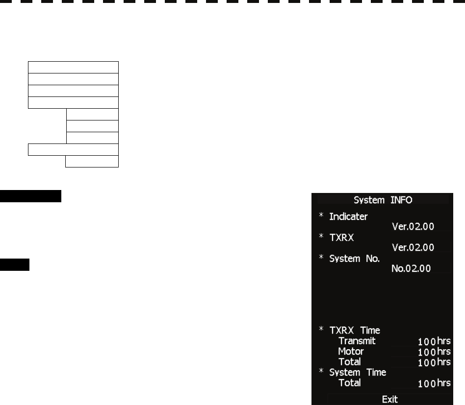
8─17
8.3.1.6 System INFO
Displays the current system information.
Indicator Processor software version information
TXRX Scanner software version information
System No. System number
TXRX Time
Total Total operating time of the scanner unit (Total power-on time of the antenna unit)
Motor Total operating time (Total power-on time)
Transmit Total transmitting time (Total time during which radar was transmitted)
System Time
Total Total operating time of the display unit (Total power-on time of the display unit)
Procedure 1 Press [6] key while the Test Menu is
open.
The System INFO Menu will appear.
Exit 1 Press [RADAR MENU] key.
The menu will be closed.
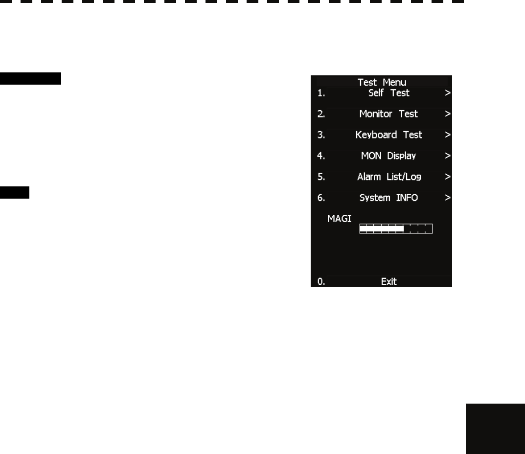
8.3 PERFORMANCE CHECK
8─18
8
yyyy
yyyy
8.3.1.7 MAGI
Displays the MAGI bar indicating the magnetron current to check.
Procedure 1 Check if the MAGI bar in the Test Menu
reads the value below in a range of 24
NM.
6 kW: 4 to 5 scale marks
10 kW: 4 to 7 scale marks
25 kW: 6 to 9 scale marks
Exit 1 Press [RADAR MENU] key.
The menu will be closed.
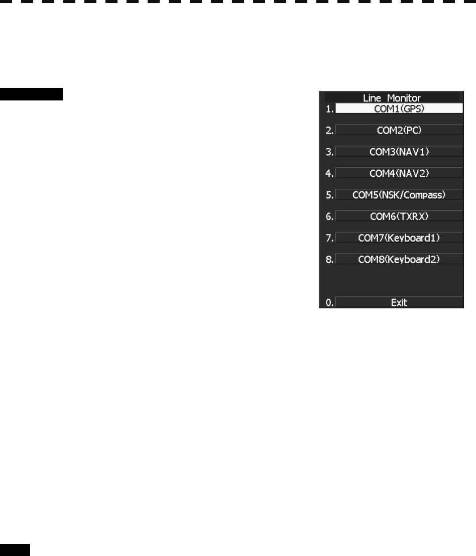
8─19
8.3.2 Line Monitor
Serial communication data can be seen on the built-in Line monitor.
Line monitor can be used to make sure that the serial data are received properly.
Procedure 1 Hold down [RADAR MENU] key.
The Code Input Menu will appear.
2 Press [0] key.
3 Move the cursor onto the “ENT” button
in the Code Input menu, and press
[ENT] key.
The Adjust Menu will appear.
4 Press [5] key.
The COM Port Setting Menu will appear.
5 Press [7] key.
The LINE MONITOR menu will appear.
6 Select the Communication port you want to see, pressing the numeric
keys [1] to [8].
The LINE MONITOR appears.
Refer to the next page for the display.
Each ports on the menu repesets followingconnectors.
COM1(GPS) J3 GPS
COM2(PC) J8 NMEA
COM3(NAV1) J6 AIS/NMEA
COM4(NAV2) J9 AUX (Option)
COM5(NSK/COMPASS) J5 GYRO / COMPASS
COM6(TXRX) J2 SCANNER
COM7(KEY BOARD1) J4 KEY BOARD
COM8(KEY BOARD2) J9 AUX (Optioon)
Exit 1 Press [0] key.
2 Press [RADAR MENU] key.
The Main Menu will reappear.
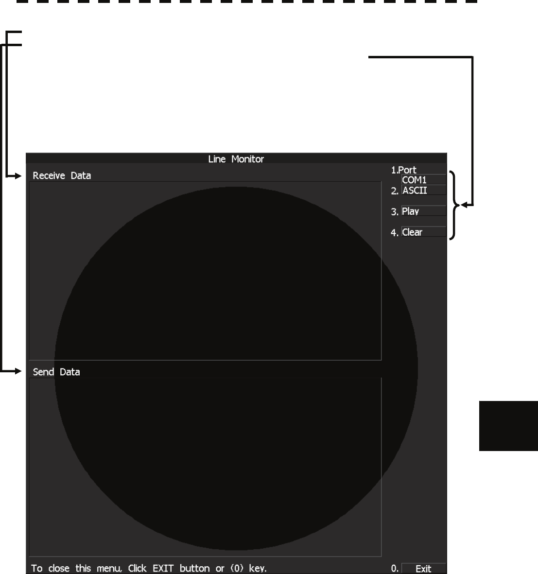
8.3 PERFORMANCE CHECK
8─20
8
yyyy
yyyy
LINE MONITOR display
Received data ; The received serial communication data are displayed.
Transmitted data ; The transmitted serial communication data are displayed.
On-screen controls ; Line monitor can be controled by the following soft keys
on the upper right corner of the LINE MONITOR.
1. Port selection ; This key selects communication port to be displayed.
2. Data format selection ; This key switches the data format
between ASCII format and binary fomat.
3. Play and Stop ; This key activates or deactivates data display renewing.
4. Clear ; The key clears all data.
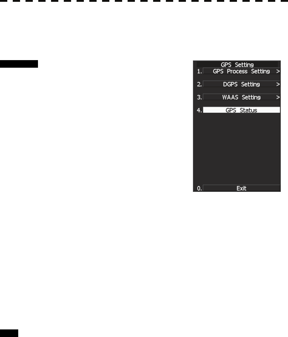
8─21
8.3.3 GPS Reception Status Display (GPS Status)
Display the reception status of the GPS receiver (GPS, DGPS and WAAS receivers) currently connected.
Seize the status of satellites that are currently performing positioning.
Procedure 1 Press [RADAR MENU] key.
The Main Menu will appear.
2 Press [7] key.
NAV Equipment Setting Menu will appear.
3 Press [7] key.
GPS Setting Menu will appear.
4 Press [4] key.
GPS Status Menu will appear.
<The alternative procedure for steps above>
1 Hold down [RADAR MENU] key.
The Code Input Menu will appear.
2 Press [0] key.
3 Move the cursor onto the “ENT” button in the Code Input menu, and
press [ENT] key.
The Adjust Menu will appear.
4 Press [6] key.
NAV Equipment Setting menu opens.
5 Perform steps 3 and 4 in the “Procedure” above.
Exit 1 Press [0] key.
The Status Menu will be closed.
2 Press [RADAR MENU] key.
The menu will be closed.
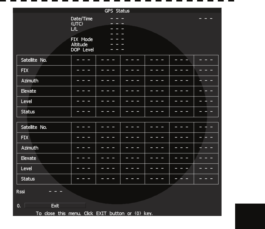
8.3 PERFORMANCE CHECK
8─22
8
yyyy
yyyy
GPS Status Display
The following items are to appear on the Status display.
DATE/TIME : Local date and time
(UTC) : Greenwich Mean Time
L/L : Current latitude and longitude
FIX MODE : Fix Mode (2D positioning/3D positioning)
ALT : Altitude of own ship. Setting the Fix Mode to 2D displays the antenna height initially
set.
DOP LEVEL : Precision of positioning results. As the value is smaller, the indicated precision is
higher.
SATELLITE No. : Satellite No.
FIX : Is positioning data used?
AZIMUTH : Azimuthal angle of satellite
ELEVATE : Elevation angle of satellite
LEVEL : Reception signal level
STATUS : Current status of satellite
RSSI : Reception intensity of Beacon station
8─23
8.4 REPLACEMENT OF MAJOR PARTS
The system includes parts that need periodic replacement. The parts should be replaced as scheduled. Use of
parts over their service life can cause a system failure.
WARNING
Direct exposure to electromagnetic waves at close
range will have adverse effects on the human
body. When it is necessary to get close to the
scanner for maintenance or inspection purposes,
make sure to turn the indicator power switch to
"OFF" or "STBY."
Direct exposure to electromagnetic waves at close
range will have adverse effects on the human
body.
When conducting maintenance work, make sure to
turn off the power and unplug the power connector
J1 of the radar process unit so that the power
supply to the equipment is completely cut off.
Some equipment components can carry electrical
current even after the power switch is turned off,
and conducting maintenance work without
unplugging the power connector may result in
electrocution, equipment failure, or accidents.
8.4 REPLACEMENT OF MAJOR PARTS
8─24
8
yyyy
yyyy
CAUTION
Turn off the main power source before replacing
parts. Otherwise, an electric shock or trouble
may be caused.
Before replacing the magnetron, turn off the main
power source and wait for 5 minutes or more until
the high voltage circuits are discharged.
Otherwise, an electric shock may be caused.
Take off your wrist watch when bringing your
hands close to the magnetron.
Otherwise, your watch may be damaged because
the magnetron is a strong magnet.
Two or more persons shall replace the liquid
crystal monitor.
If only one person does this work, he may drop the
LCD, resulting in injury.
Even after the main power source is turned off,
some high voltages remain for a while.
Do not contact the inverter circuit in the LCD with
bare hands. Otherwise, an electric shock may be
caused.

8─25
8.4.1 Parts Required for Periodic Replacement
Here are parts required for periodic replacement
Part name Interval
1. Magnetron 4000 hours
2. Motor 10000 hours
3. LCD backlight 50000 hours
4. Fan motor 20000 hours
5. Backup battery 5 years
8.4.2 Replacement of magnetron
Before replacing the magnetron, turn off the main power source, wait for five minutes or more, and confirm
that no charge remains in the high-voltage modulator circuit.
When mounting a new magnetron, do not touch the magnet with a screwdriver or put it on an iron plate. After
replacement, connect the lead wire correctly.
Handling of Magnetron under Long-Time Storage
The magnetron that has been kept in storage for a long time may cause sparks and operate unstably when its
operation is started. Perform the aging in the following procedure:
(1) Warm up the cathode for a longer time than usually. (20 to 30 minutes in the STBY state.)
(2) Start the operation from the short pulse range and shift it gradually to the longer pulse ranges. If the
operation becomes unstable during this process, return it to the standby mode immediately. Keep the
state for 5 to 10 minutes until the operation is restarted.
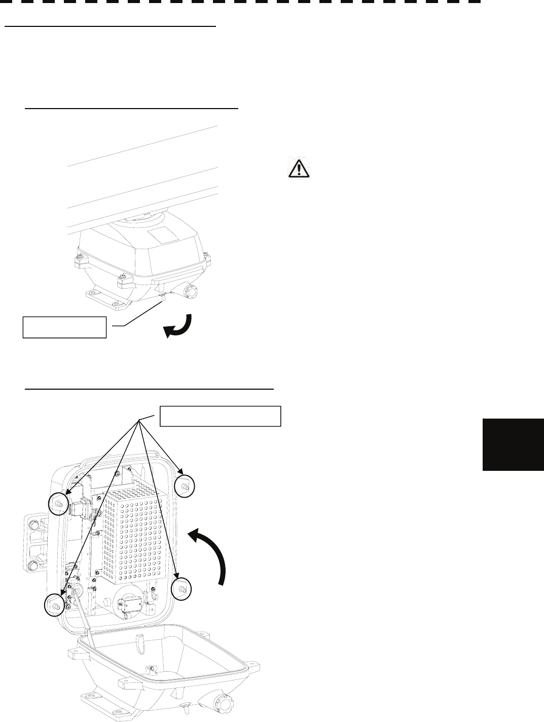
8.4 REPLACEMENT OF MAJOR PARTS
8─26
8
yyyy
yyyy
How to replace a 6kW antenna magnetron
Make sure that all radars are turned off before replacing the magnetron (if there are multiple radar devices, turn
them all off). It is also recommended that the breaker be turned off for safety.
Step 1: Turn off the antenna safety switch.
When replacing a magnetron, make sure
to first turn off the antenna safety
switch.
The switch is at the rear bottom of the antenna.
Turn off the switch.
Step 2: Remove the bolts and open the top cover.
The top cover is fixed with 4 hexagon bolts
(M8 captive screw).
OFF
Safety switch
Hexagon bolts (4 places)
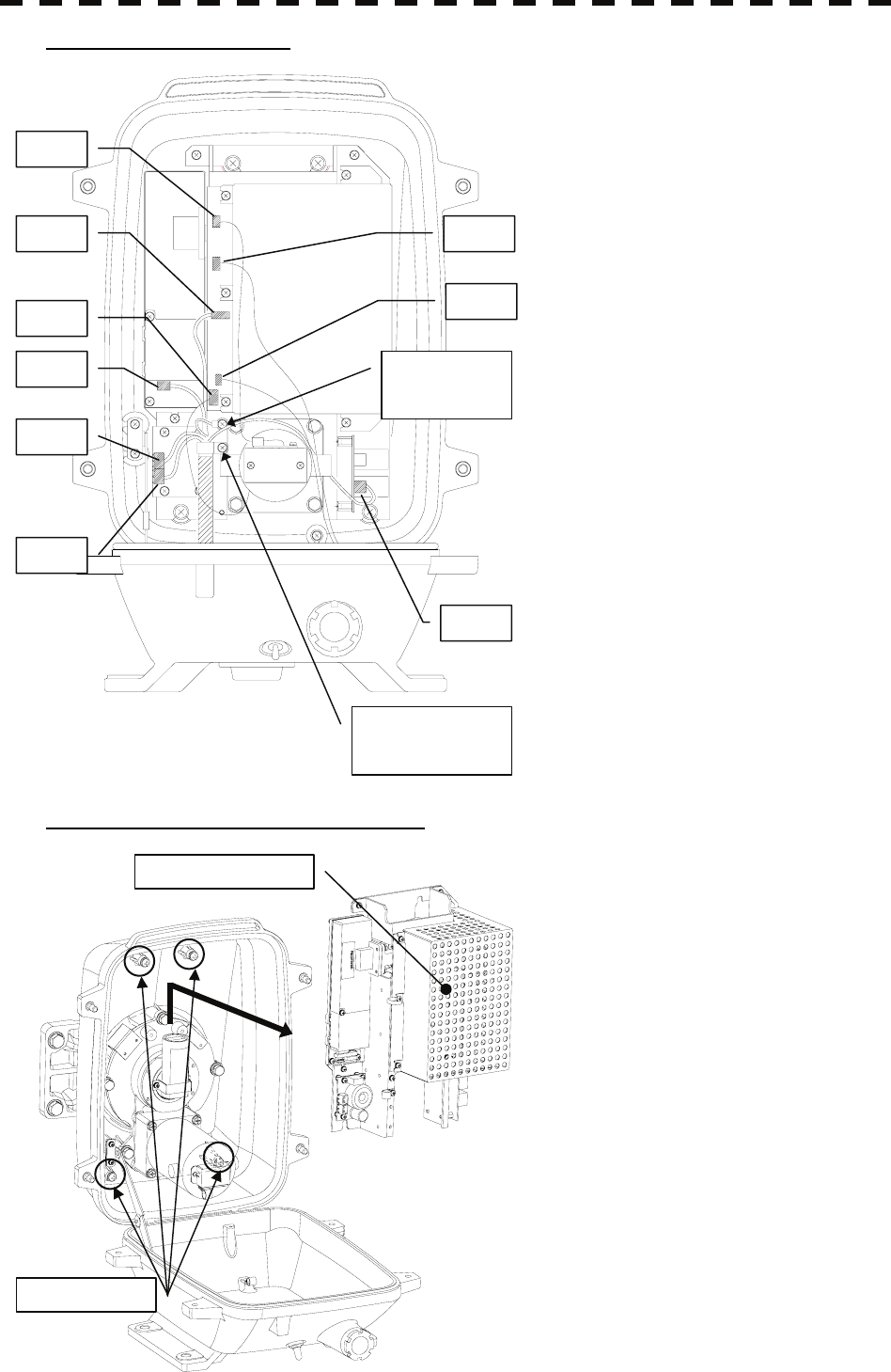
8─27
Step 3: Remove the cable.
Remove the equipment cable connectors (5
places). (J1 through J5)
Remove the safety switch connectors (2
places). (J15 and J16)
Remove the motor connector (2 places).
(J11 and J13)
Remove 9 connectors in total.
Remove the screws (1 place) and remove the
ground terminal.
Remove the screw (1 place) and remove the
cable clamp as well as the equipment cable.
Step 4: Remove the transmitter-receiver.
Loosen all the screws (4 places).
Slide upward and remove the
transmitter-receiver.
J2
J1
J3
J4
Cable clamp
screw (1 place)
Ground
terminal
screw (1 place)
J5
J11
J13
J16
J15
Screws (4 places)
Transmitter-receiver
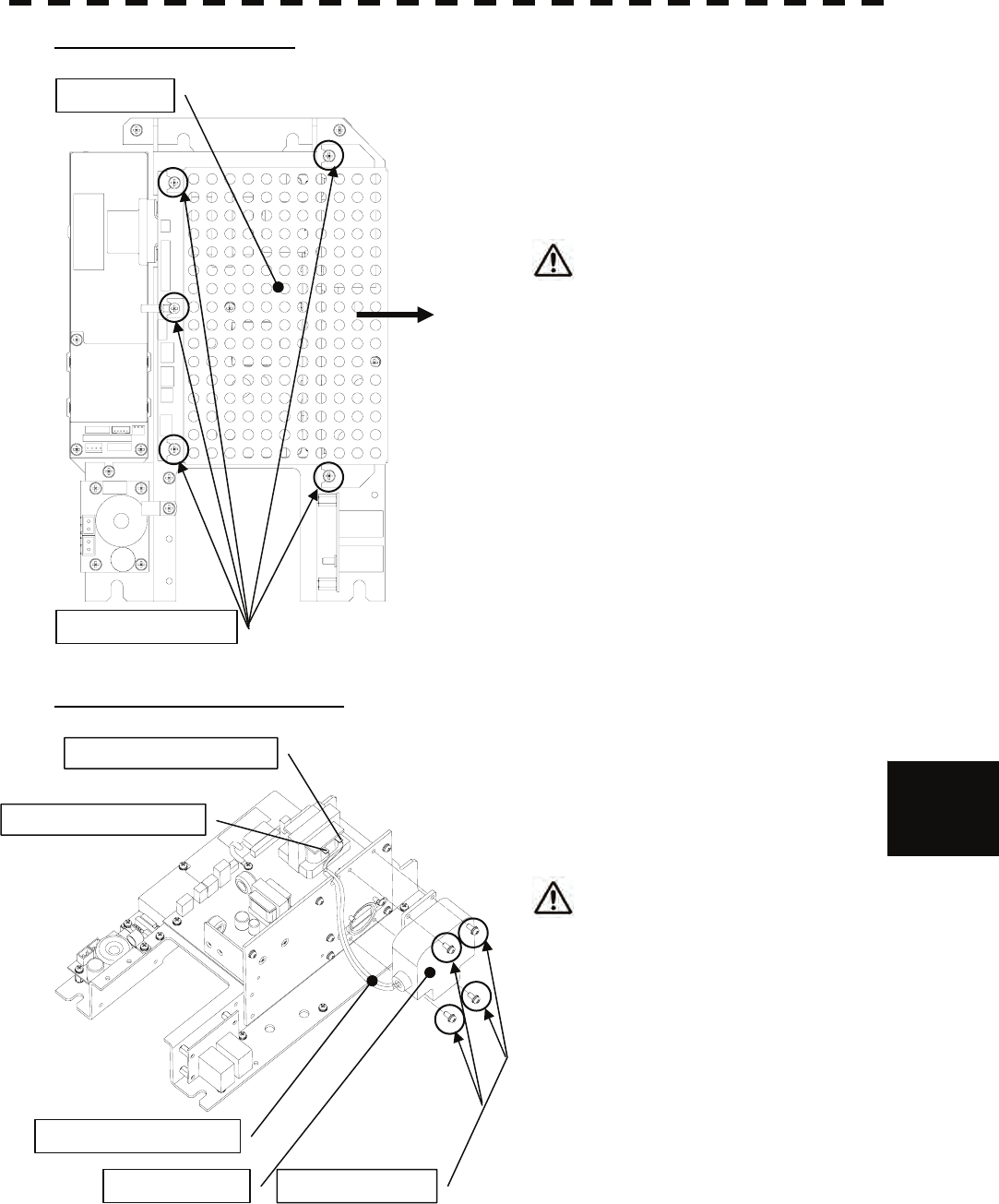
8.4 REPLACEMENT OF MAJOR PARTS
8─28
8
yyyy
yyyy
Step 5: Remove the cover.
Loosen all the screws (5 places).
Slide the cover to the right and remove it.
Use a shielded screw driver.
Metal (tools) may deteriorate if they
come in contact with the magnetron.
Remove the screws (4 places).
Remove the magnetron cable (solder).
Replace the magnetron.
Step 6: Replace the magnetron.
Two silicon tubes are moved to the magnetron
cable for the exchange and it changes it.
Replace the magnetron.
Please solder with a correct terminal
when you solder a yellow terminal and
a green terminal with the pulse
transformer. Moreover, please note that
solder might not fall on the circuit when
soldering.
Reverse the order to complete the procedure.
Make sure that all bolts and screws are
tightened again, and all cables are properly
re-connected.
This completes the magnetron replacement
procedure.
Cover
Screws (5 places)
Magnetron
Silicon tubes (2 pieces)
Screws (4 places)
Green terminal (solder)
Yellow terminal (solder)
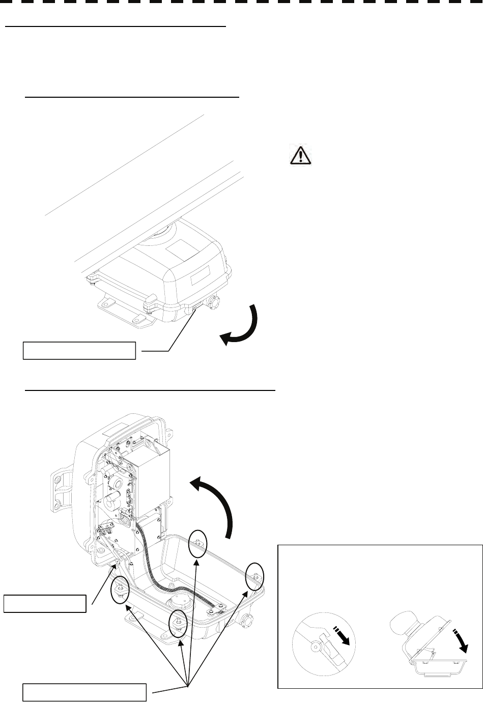
8─29
How to replace a 10 kW antenna magnetron
Make sure that all radars are turned off before replacing the magnetron (if there are multiple radar devices, turn
them all off). It is also recommended that the breaker be turned off for safety.
Step 1: Turn off the antenna safety switch.
When replacing a motor, make sure to
first turn off the antenna safety switch.
The switch is at the rear bottom of the antenna.
Turn off the switch.
Step 2: Remove the bolts and open the top cover.
The top cover is fixed with 4 hexagon bolts
(M8 captive screw).
Remove the bolts and fully open the top cover
such that the stopper of the joint fitting is
locked.
OFF
Safety switch
Hexagon bolts (4 places)
Joint fitting
* When closing the top cover
Release the stopper of the joint fitting
before closing the top cover.
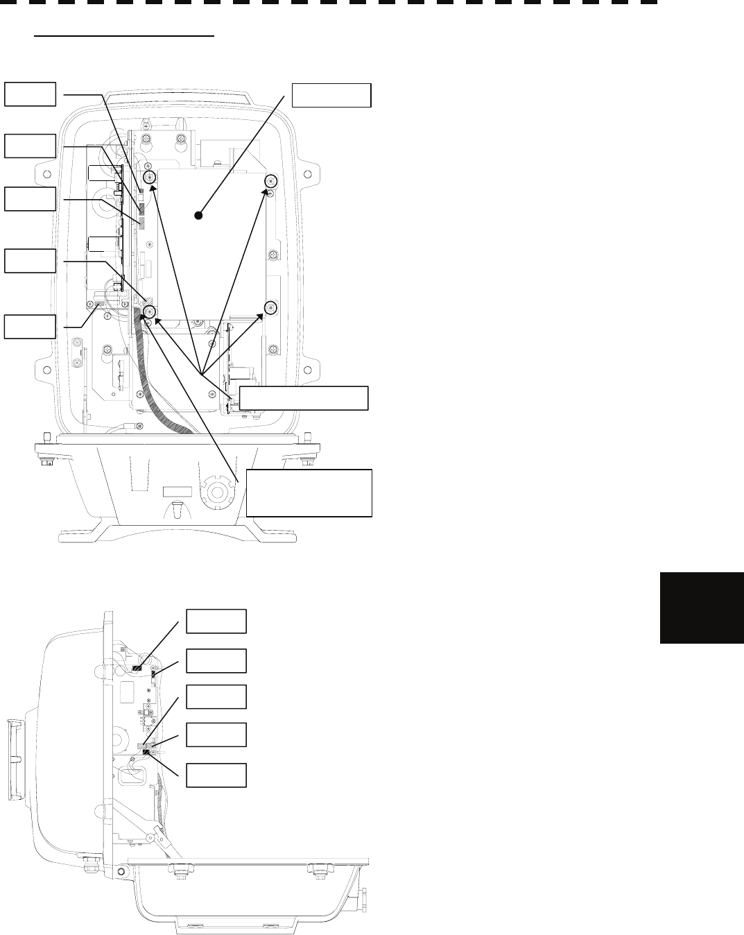
8.4 REPLACEMENT OF MAJOR PARTS
8─30
8
yyyy
yyyy
Step 3: Remove the cable.
Loosen all the screws (4 places).
Slide the cover to the left and remove it.
Remove the encoder connector (1 place).
(J209)
Remove the equipment cable connectors
(5 places).
(J1 through J5)
Remove the safety switch connectors
(2 places).
(J210 and J1504)
Remove the motor connector (2 places).
(J1502 and J125)
Remove 10 connectors in total.
* When a PM monitor (optional) is installed,
remove the connectors (2 places) and then
remove the screwed ground terminal.
Remove the screw (1 place) and remove the
cable clamp as well as the equipment cable.
J209
J210
J1
J2
J3
Screws (4 places)
Cover
Cable clamp screw
(1 place)
J1502
J125
J4
J5
J1504
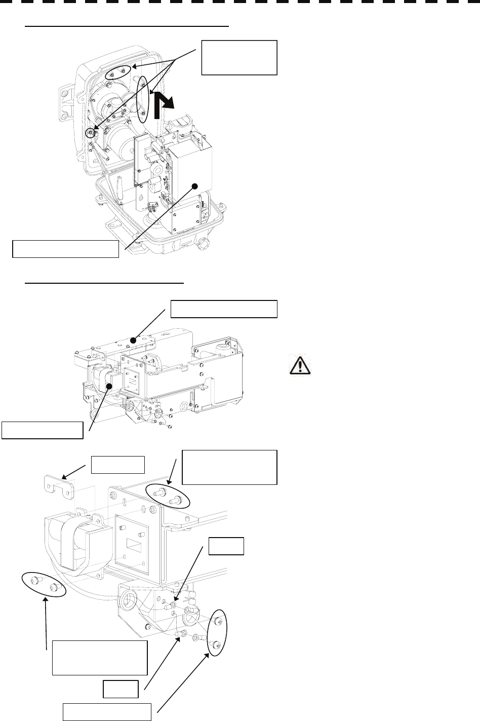
8─31
Step 4: Remove the transmitter-receiver.
Loosen all the hexagon bolts.
Slide upward and remove the
transmitter-receiver.
Step 5: Replace the magnetron.
Remove the screws (2 places) and remove the
magnetron cable.
Use a shielded screw driver.
Metal (tools) may deteriorate if they
come in contact with the magnetron.
Remove the screws (4 places) and remove the
magnetron.
Set the new magnetron in place.
Fix the magnetron and pulse transformer
cables (yellow and green, respectively)
carefully in place.
Reverse the order to complete the procedure.
Make sure that all bolts and screws are
tightened again, and all cables are properly
re-connected.
This completes the magnetron replacement
procedure.
Transmitter-receiver
Hexagon bolts
(5 places)
Transmitter-receiver
Magnetron
Screws
(2 on the back side)
Nut plate
Screws
(2 on the front side)
Green
Yellow
Screws (2 places)
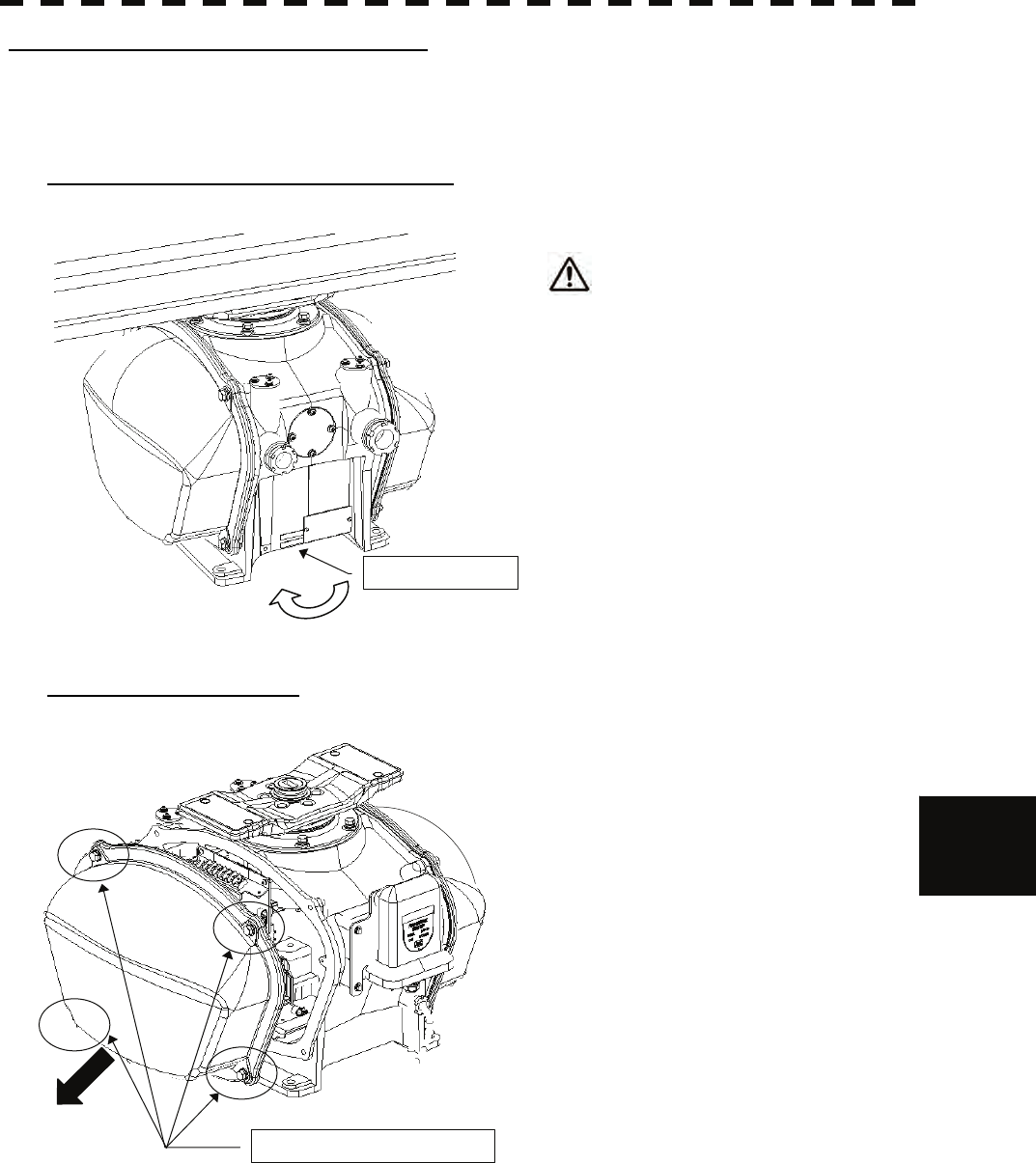
8.4 REPLACEMENT OF MAJOR PARTS
8─32
8
yyyy
yyyy
How to replace a 25 kW antenna magnetron
Make sure that all radars are turned off before replacing the magnetron (if there are multiple radar devices, turn
them all off). It is also recommended that the breaker be turned off for safety.
Step 1: Turn off the antenna safety switch.
When replacing a magnetron, make sure
to first turn off the antenna safety
switch.
The switch is at the rear bottom of the antenna.
Turn off the switch.
Step 2: Remove the cover.
The magnetron is placed on the right hand side
(starboard side) of the antenna. Therefore,
remove the right cover.
The cover is fixed with 4 hexagon bolts (M8
Captive Screw).
Place the cover in a safe place.
Prevent dust from being attached to the gasket.
Safety switch
OFF
Hexagon bolts (4 places)
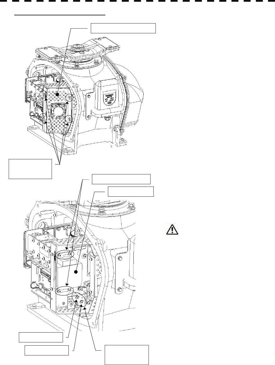
8─33
Step 3: Replace the magnetron.
Remove the screws (M4X10, at 4 places) and
remove the magnetron cover.
Remove the screws (M4X12, at 2 places) and
remove the magnetron cable.
Use a shielded screw driver.
Metal (tools) may deteriorate if they
come in contact with the magnetron.
Remove the screws (M4X12, at 4 places) and
remove the magnetron.
Do not lose the removed screws.
Set the new magnetron and cable in place.
Reverse the order to complete the procedure.
Make sure that all bolts and screws are tightened again, and all cables are properly re-connected.
This completes the magnetron replacement procedure.
Screws
(4 places)
Magnetron cover
Magnetron
Screws (4 places)
Cable: yellow
Cable: green Screws
(2 places)
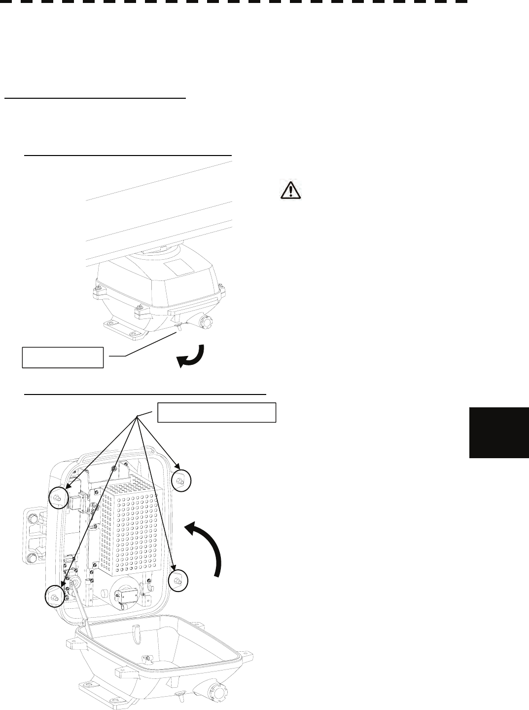
8.4 REPLACEMENT OF MAJOR PARTS
8─34
8
yyyy
yyyy
8.4.3 Motor Replacement
First remove the cover, and then remove the socket of the motor. Remove the screws that hold the motor, and
remove the motor. Connect the leads correctly after replacing the motor.
How to replace a 6kW antenna motor
Make sure that all radars are turned off befor replacing the magnetron (if there are multiple radar devices, turn
them all off). It is also recommended that the breaker be turned off for safety.
Step 1: Turn off the antenna safety switch.
When replacing a motor, make sure to
first turn off the antenna safety switch.
The switch is at the rear bottom of the antenna.
Turn off the switch.
Step 2: Remove the bolts and open the top cover.
The top cover is fixed with 4 hexagon bolts
(M8 captive screw).
OFF
Safety switch
Hexagon bolts (4 places)
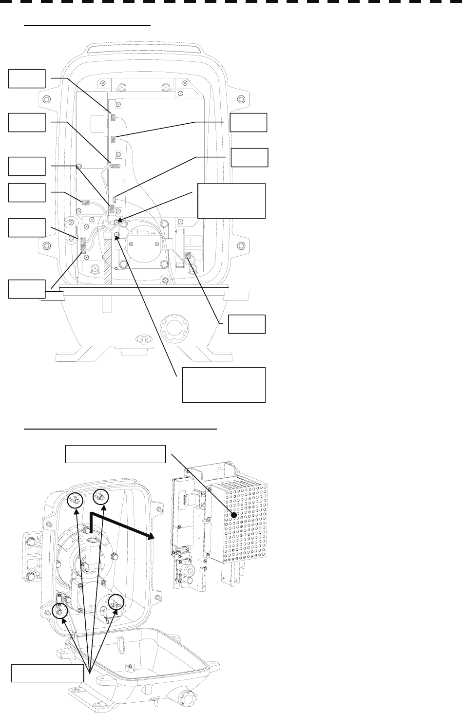
8─35
Step 3: Remove the cable.
Remove the equipment cable connectors (5
places).
(J1 through J5)
Remove the safety switch connectors (2
places).
(J15 and J16)
Remove the motor connectors (2 places).
(J11 and J13)
Remove 9 connectors in total.
Remove the screw (1 place) and remove the
ground terminal.
Remove the screw (1 place) and remove the
cable clamp as well as the equipment cable.
Step 4: remove the transmitter-receiver.
Loosen all the screws (4 places).
Slide upward and remove the
transmitter-receiver.
J2
J1
J3
J4
Cable clamp
screw (1 place)
Ground
terminal
screw (1 place)
J5
J11
J13
J16
J15
Screws (4 places)
Transmitter-receiver

8.4 REPLACEMENT OF MAJOR PARTS
8─36
8
yyyy
yyyy
Step 5: Replace the motor.
Remove the hexagon bolts (M6, at 4 places)
and then remove the motor.
Apply grease to the gears of the new motor,
and bolt the new motor.
Tighten the hexagonal bolts using a torque
wrench (72 kgf・cm).
Reverse the order to complete the procedure.
Make sure that all bolts and screws are
tightened again, and all cables are properly
re-connected.
This completes the motor replacement proce
Motor
Hexagon bolts
(4 places)
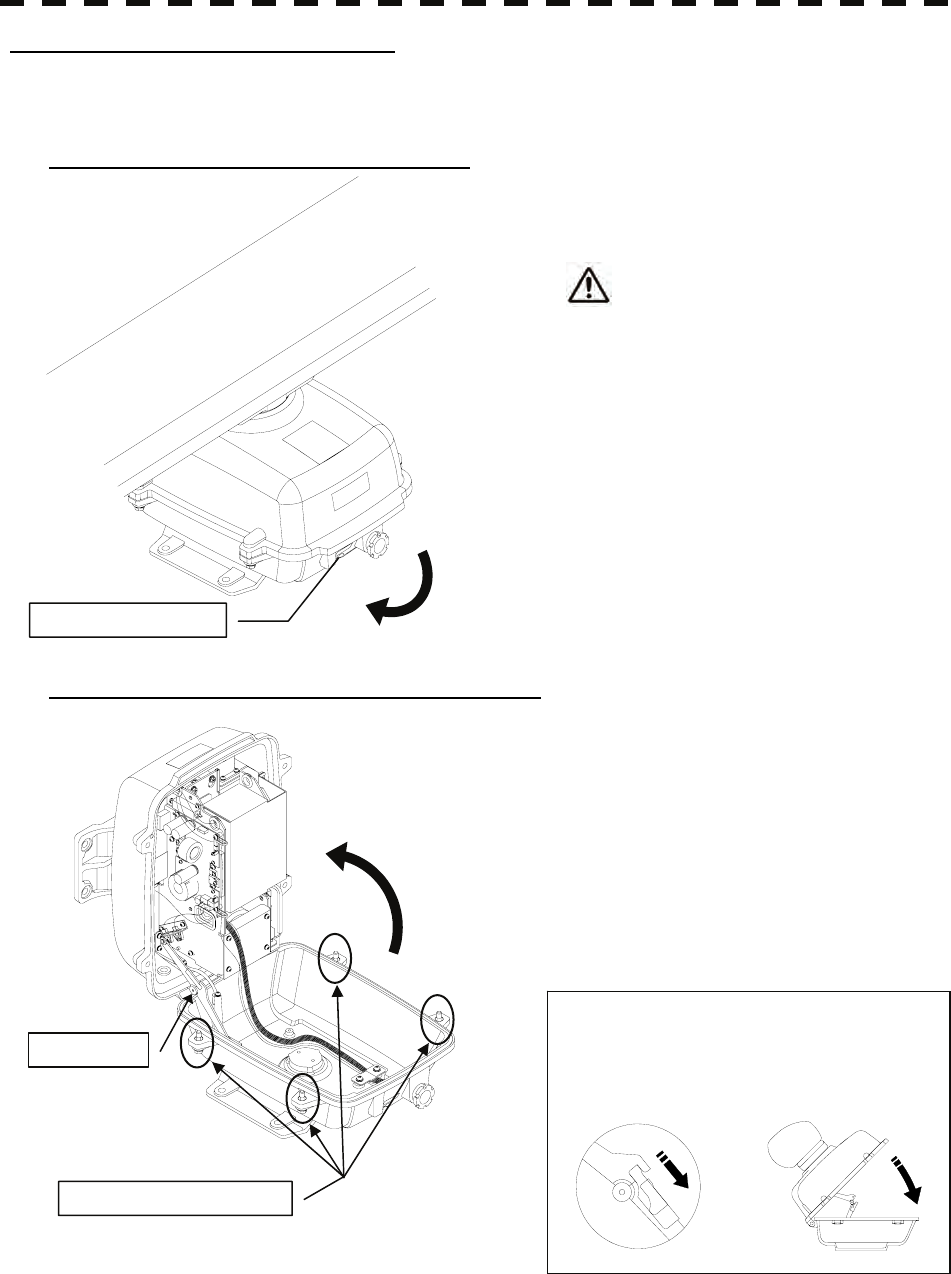
8─37
How to replace a 10 kW antenna motor
Make sure that all radars are turned off before replacing the magnetron (if there are multiple radar devices, turn
them all off). It is also recommended that the breaker be turned off for safety.
Step 1: Turn off the antenna safety switch.
When replacing a motor, make sure to
first turn off the antenna safety switch.
The switch is at the rear bottom of the antenna.
Turn off the switch.
Step 2: Remove the bolts and open the top cover.
The top cover is fixed with 4 hexagon bolts
(M8 captive screw).
Remove the bolts and fully open the top cover
such that the stopper of the joint fitting is
locked.
* When closing the top cover
Release the stopper of the joint fitting
before closing the top cover.
OFF
Safety switch
Hexagon bolts (4 places)
Joint fitting
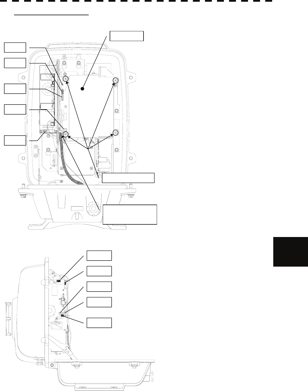
8.4 REPLACEMENT OF MAJOR PARTS
8─38
8
yyyy
yyyy
Step 3: Remove the cable.
Loosen all the screws (4 places).
Slide the cover to the left and remove it.
Remove the encoder connector (1 place).
(J209)
Remove the equipment cable connectors
(5 places).
(J1 through J5)
Remove the safety switch connectors
(2 places).
(J210 and J1504)
Remove the motor connectors (2 places).
(J1502 and J125)
Remove 10 connectors in total.
* When a PM monitor (optional) is installed,
remove the connectors (2 places) and then
remove the screwed ground terminal.
Remove the screw (1 place) and remove the
cable clamp as well as the equipment cable.
J1502
J125
J4
J5
J1504
J209
J210
J1
J2
J3
Screws (4 places)
Cover
Cable clamp screw
(1 place)
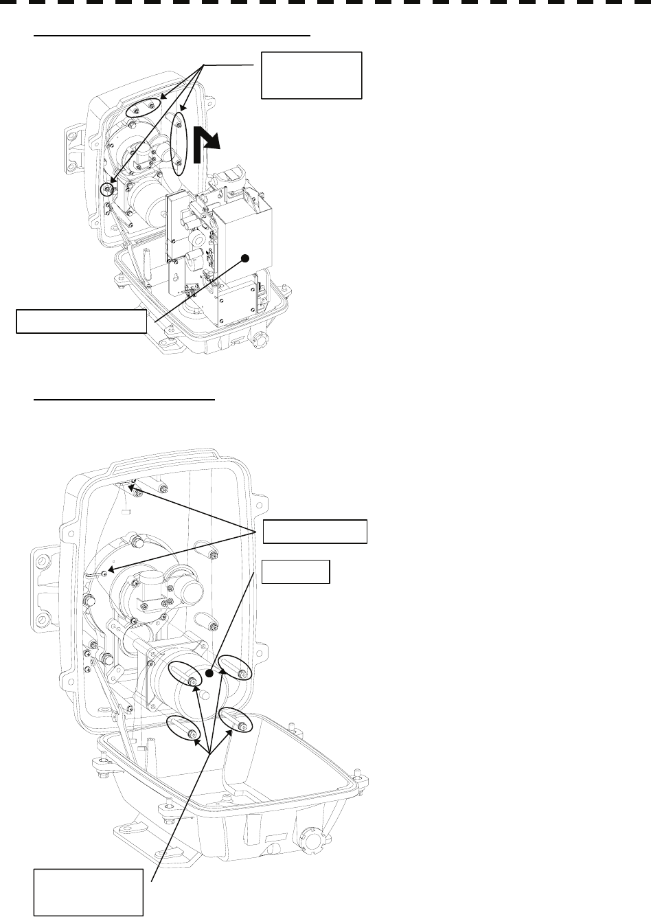
8─39
Step 4: Remove the transmitter-receiver.
Loosen all the hexagon bolts (5 places).
Slide upward and remove the
transmitter-receiver.
Step 5: Replace the motor.
Remove the motor cable from the cable clamp.
Remove the hexagon bolts (M6, at 4 places)
and then remove the motor.
Apply grease to the gears of the new motor,
and bolt the new motor.
Tighten the hexagonal bolts using a torque
wrench (72 kgf·cm).
Reverse the order to complete the procedure.
The rotor of the motor rotates. Clamp the
cable such that it will not touch the rotor.
Make sure that all bolts and screws are
tightened again, and all cables are properly
re-connected.
This completes the motor replacement
procedure.
Transmitter-receiver
Hexagon bolts
(5 places)
Motor
Cable clamp
Hexagon bolts
(4 places)
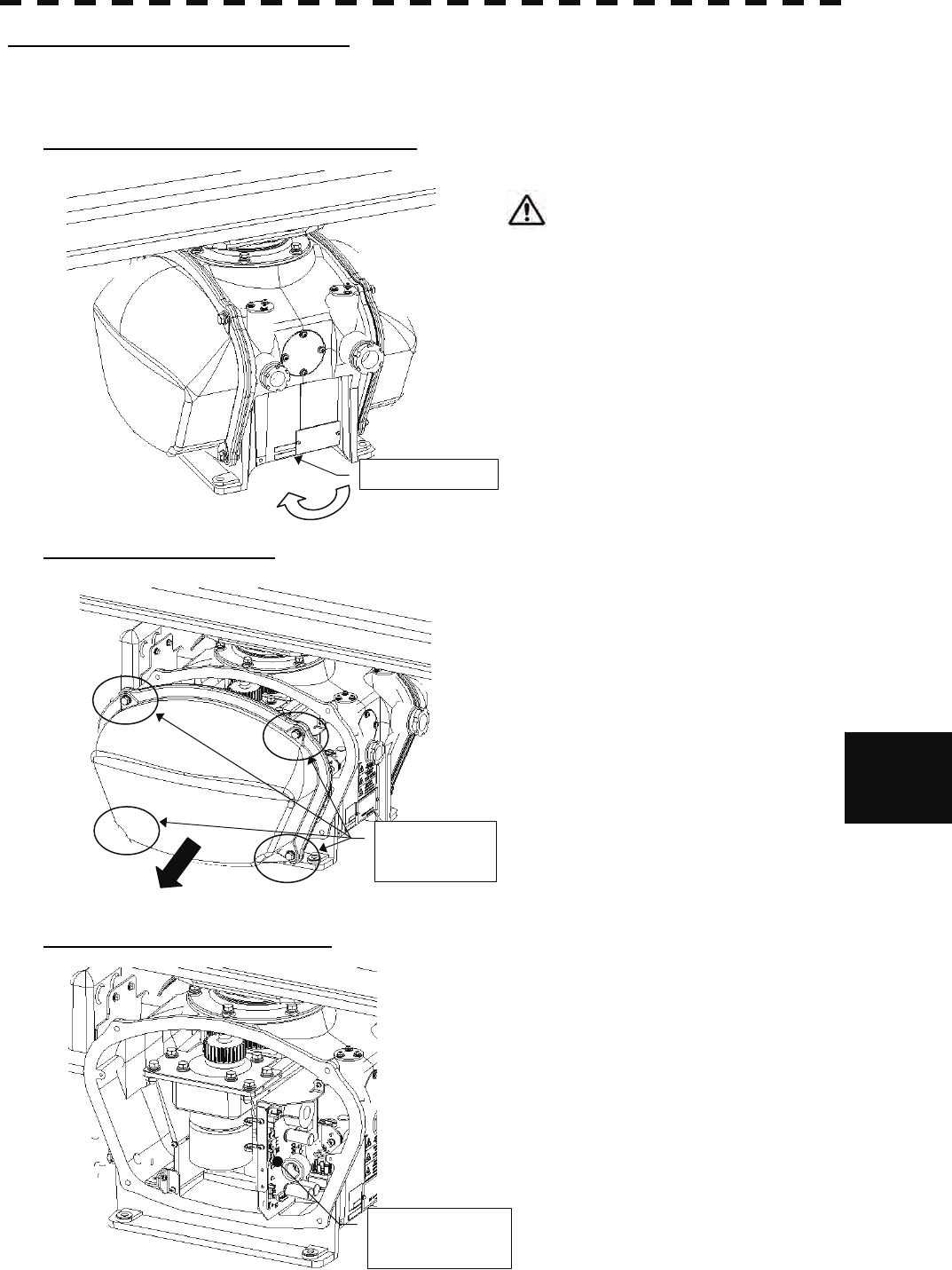
8.4 REPLACEMENT OF MAJOR PARTS
8─40
8
yyyy
yyyy
How to replace a 25 kW antenna motor
Make sure that all radars are turned off before replacing the magnetron (if there are multiple radar devices, turn
them all off). It is also recommended that the breaker be turned off for safety.
Step 1: Turn off the antenna safety switch.
When replacing a motor, make sure to
first turn off the antenna safety switch.
The switch is at the rear bottom of the antenna.
Turn off the switch.
Step 2: Remove the cover.
The motor is placed on the left hand side (port
side) of the antenna.
Therefore, remove the left cover.
The cover is fixed with 4 hexagon bolts (M8
captive screw).
Place the cover in a safe place.
Prevent dust from being attached to the gasket.
Step 3: Remove the motor cable.
Remove the motor cable connected to the
motor control power circuit.
Safety switch
OFF
Hexagon bolts
(4 places)
Motor control
power circuit
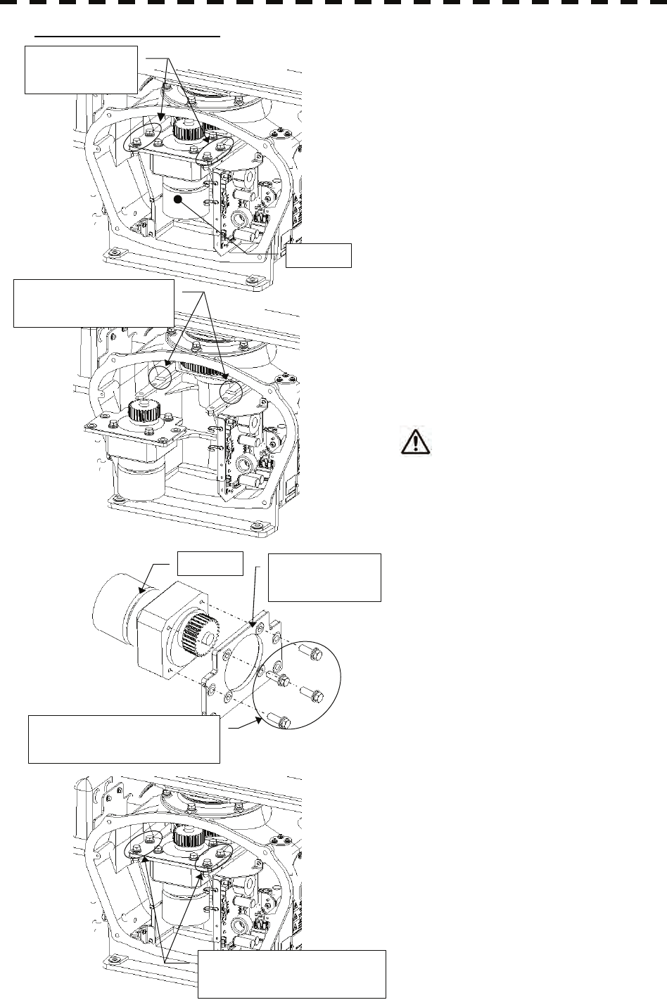
8─41
Step 4: Replace the motor.
The motor is fixed with 4 hexagon bolts (M8 x
20 SW W, embedded type).
Remove all the hexagon bolts (4 pieces).
Remove the motor.
The motor weighs about 6 kg.
Handle it carefully.
Attach the mounting plate to the new motor.
Remove the motor mounting plate from the
removed motor. The mounting plate is fixed
with 4 hexagon bolts (M8 x 30 SW W,
embedded type).
Attach the removed parts to the new motor.
Make sure to properly tighten all the hexagon
bolts at the optimal torque (210 kgf·cm).
Place the motor in the antenna.
Press the motor against the protrusions from
the arms of the case, and adjust its position to
minimize the backlash.
Make sure to properly tighten all the hexagon
bolts at the optimal torque (140 kgf·cm).
Apply grease to the gear after placing the
motor in the case.
Motor
Hexagon bolts
(4 places)
Protrusions for adjusting
the motor position
Hexagon bolts (4 places)
Torque wrench (140 kgf·cm)
Hexagon bolts (4 places)
Torque wrench (210 kgf·cm)
Motor Motor mounting
plate
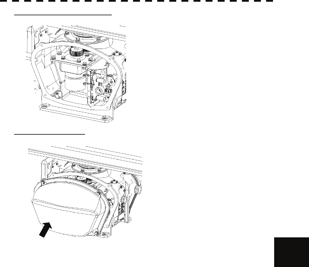
8.4 REPLACEMENT OF MAJOR PARTS
8─42
8
yyyy
yyyy
Step 5: Connect the motor cables.
Reconnect the cables to the motor control
power circuit.
Step 6: Put the cover on.
Before attaching the cover to the antenna,
make sure that the gasket of the cover is not
deformed or cracked.
Also, remove any dust attached to the gasket.
Fix the cover with 4 hexagon bolts.
Failure to tighten the bolts or loose bolts will
affect waterproof property; therefore, make
sure to tighten all the bolts at the optimal
torque.
Turn on the antenna safety switch.
This completes the motor replacement procedure.

8─43
8.4.4 Replacement of Diode Limiter (A303)
Remove the 4 screws fixing the receiver. Remove the 4 screws fixing the diode and the limiter, and remove
diode limiter. When mounting the diode limiter, take care of the mounting direction and mount it in the arrow
direction facing it the receiver front end.
Connect the wiring in the same way as before the replacement.

8.4 REPLACEMENT OF MAJOR PARTS
8─44
8
yyyy
yyyy
8.4.5 Replacement of Backup Battery
Caution: Replacement of backup battery must be made by specialized service personnel.
For details, refer to Service Manual.
A coin-cell battery maintains radar system configuration, date, and time information while power off condition.
radar system configuration is saving to non-volatile memory at fixed intervals.
How to Replacement of Backup Battery
1. Remove the Coin-Cell Battery from the Holder
Be careful, don't break holder.
3. Fix the Coin-Cell Battery in the Holder
Turn up + surface.
Battery type : CR2450

8─45

SECTION 9
TROUBLESHOOTING AND
AFTER-SALES SERVICE
9.1 FAULT FINDING................................................ 9-1
9.1.1 List of Alarms and other Indications ....... 9-1
9.1.2 Operation Checking .................................. 9-4
9.1.3 Fuse Checking........................................... 9-4
9.2 TROUBLE SHOOTING...................................... 9-5
9.2.1 Spares......................................................... 9-6
9.2.2 Special Parts .............................................. 9-8
9.2.3 Circuit Block to be Repaired .................... 9-8
9.3 AFTER-SALES SERVICE ................................9-11
9.3.1 Keeping period of maintenance parts ....9-11
9.3.2 When you Request for Repair .................9-11
9.3.3 Recommended Maintenance...................9-11
9─1
9.1 FAULT FINDING
In case of semiconductor circuits, it is deemed that there are few cases in which the used semiconductor
devices have inferior quality or performance deterioration except due to insufficient design or inspection
or by other external and artificial causes. In general, the relatively many causes are disconnection in a
high-value resistor due to moisture, a defective variable resistor and poor contact of a switch or relay.
Some troubles are caused by defective parts, imperfect adjustment (such as tuning adjustment) or
insufficient service (such as poor cable contact). It will also be effective to check and readjust these points.
9.1.1 List of Alarms and other Indications
If any of the following alarm occurs, the system displays the alarm message in red in order to attract the
attention of operator. Other messages are displayed with the suitable color which is yellow or blue
depending on the level of message importance.
Alarm: Red ・Collision-related Alarm
・Navigation Alarm
・System Alarm
Warning: Yellow ・System Warning
Information: Blue ・Operation Information
Table 9-1 List of Notification
Message Class Description ALR No.
CCRP Changed INFO CCRP is automatic changed.
Copying INFO Display is capturing to file.
GPS (HDOP) Warning The HDOP level is increased (Decrease in the GPS accuracy.).
GPS(Low Integrity) Warning GPS Low integrity
MON Test Warning Performance monitor is active.
Position Reset INFO Change the latitude and longitude sentence.
Set GYRO INFO Set a course with the gyro.
TM Reset INFO Use care of resetting TM.
TXRX(Standby) INFO Scanner Ready for transmission
Weather Information INFO Weather information received.
ALR No: Unique alarm number in ALR sentence and ACK sentence.
Table 9-2 List of Target Tracking Alarms and AIS Function Critical Alarms
Message Class Description ALR No.
AIS(CPA/TCPA) Alarm There is a AIS dangerous target. 931
TT(CPA/TCPA) Alarm There is a TT dangerous target. 301
ALR No: Unique alarm number in ALR sentence and ACK sentence.

9.1 FAULT FINDING
9─2
9
y
yyyy
yyyy
Table 9-3 List of RADAR Alarm, Target Tracking Alarms and AIS Function Alarms
Message Class Description ALR No.
AIS
(ACT 95% Capacity) INFO Over 95% of the maximum number of AIS targets to be activated.
AIS(ACT MAX) INFO Maximum number of AIS targets to be activated. 334
AIS(CPA/TCPA) Alarm There is a AIS dangerous target. 931
AIS(Data) Alarm AIS communication error.
The data of communication with the AIS unit contains an error. 918
AIS(Lost) Alarm AIS Target has been lost.
(Failure in receiving AIS target data for a specified time.) 335
AIS(New Target) Alarm AIS Automatic new target acquisition in the automatic acquisition
area. 302
AIS(Time Out) Alarm No communication with AIS.
The AIS transponder is not connected correctly or the power is
turned off. 116
AIS 95% Capacity INFO Over 95% of the maximum number of AIS targets.
AIS Alarm *** Alarm Alarm information issued with the ALR sentence by the AIS.
*** is a 3-digit number which is Local Alarm No in the ALR
sentence.
AIS MAX Target INFO Maximum number of AIS targets. 333
AIS PROC(Data) Alarm AIS I/F communication error.
The data of communication with the AIS unit. 919
AIS PROC(Time Out) Alarm No communication with AIS I/F.
The AIS unit is nor connected or is not operating. 328
REF TT(Lost) Alarm Decrease in the reference target accuracy.
(Reference TT target has been lost.) 337
Radar Alarm(In) Alarm Targets have entered the radar alarm range. 933
Radar Alarm(Out) Alarm Targets have left the radar alarm range. 934
TT(CPA/TCPA) Alarm There is a TT dangerous target. 301
TT(Data*) Alarm Communication error with the TT processing unit.
The target tracking unit is malfunctioning.
323
914
915
916
TT(Lost) Alarm TT Target has been lost.
(Failure in tracking the target that has been under tracking.) 336
TT
(MAX 95% Capacity) INFO Over 95% of the maximum number of targets to be tracked.
TT(MAX Target) INFO The maximum number of targets is under acquisition. 338
TT(New Target) Alarm TT Automatic new target acquisition in the automatic acquisition
area. 932
ALR No: Unique alarm number in ALR sentence and ACK sentence.

9─3
Table 9-4 List of Route Error Messages and Warnings
Message Class Description ALR No.
Radar Alarm(In) Alarm Targets have entered the radar alarm range. 933
Radar Alarm(Out) Alarm Targets have left the radar alarm range. 934
Route(Approach) Alarm Approach the route. 938
Route(Break Off) Alarm Out of the route. 939
WPT(Arrival) Alarm Arrive at way point. 936
WPT(Break Off) Alarm Out of the way point. 937
ALR No: Unique alarm number in ALR sentence and ACK sentence.
Table 9-5 List of Operational Error Messages and Warnings
Message Class Description ALR No.
Can't Transmit INFO Transmission cannot be executed.
Tried to transmit within 5 second after standby or when the
transmitter-receiver has any trouble.
Card Full INFO Card capacity insufficient.
Delete Failed INFO Data deletion from the card failed.
Format Failed INFO Card format failed.
In Use INFO Data cannot be deleted / changed because it is being used now.
In Use INFO Data has been inputted.
Invalid Card INFO Card is not valid.
Invalid Data INFO The value is invalid.
Tried to enter any data beyond its range.
MAX Point INFO The maximum number of points has been reached.
Tried to enter navigation information beyond the specified.
No Card INFO Card not detected yet.
No Position Data INFO There is no position data.
Mark or line input when the latitude and longitude is invalid.
No Heading Data INFO There is no bearing data.
Target tracking operation or TM selection when bearing data is
invalid.
Not Allowed INFO General operation error.
Out of Bounds INFO The latitude cannot be displayed on the map.
Out of Bounds INFO The latitude is outside the displayable latitude range.
Out of Range INFO Out of operation range.
Read Failed INFO Data load from the card failed.
Write Failed INFO Data write to the card failed.
ALR No: Unique alarm number in ALR sentence and ACK sentence.
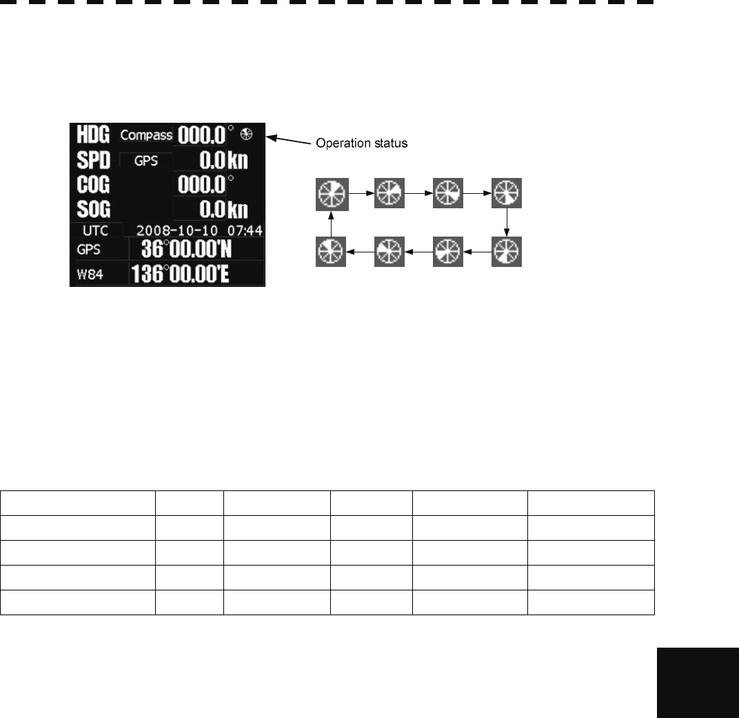
9.1 FAULT FINDING
9─4
9
y
yyyy
yyyy
9.1.2 Operation Checking
When the system is operating, the operation status (located at the upper right of the screen) is changing
pictures.
If picture freeze occurred, turn off the system and restart the system.
9.1.3 Fuse Checking
Melted fuses are caused by any clear cause. When a fuse is replaced, it is necessary to check the related
circuits even if there is no trouble. In checking, note that there is some dispersion in the fusing
characteristics. Table 9-6 shows a list of fuses used in the equipment.
Table 9-6 Fuse List
Location Parts No. Current Rating Type Protection Circuit Scanner Unit
Radar processing circuit F2 5A ST4-5AN1 I/F circuit NKE-2103 (10kw)
Radar processing circuit F3 10A ST6-10AN1 I/F circuit NKE-2103 (10kw)
Radar processing circuit F2 10A ST6-10AN1 I/F circuit NKE-2254 (25kw)
Radar processing circuit F3 10A ST6-10AN1 I/F circuit NKE-2254 (25kw)

9─5
9.2 TROUBLE SHOOTING
As this radar equipment includes complicated circuits, it is necessary to request a specialist engineer for
repair or instructions for remedy if any circuit is defective.
There are also troubles by the following causes, which should be referred to in checking or repair work.
1 Poor Contact in Terminal Board of Inter-Unit Cables
a) Poor contact in terminal board
b) The cable end is not fully connected, that it, contacted with earthed another terminal.
c) Disconnected cable wire
2 Poor Contact of Connector within Unit
Reference: This radar equipment is provided with 8-13 standard spares.
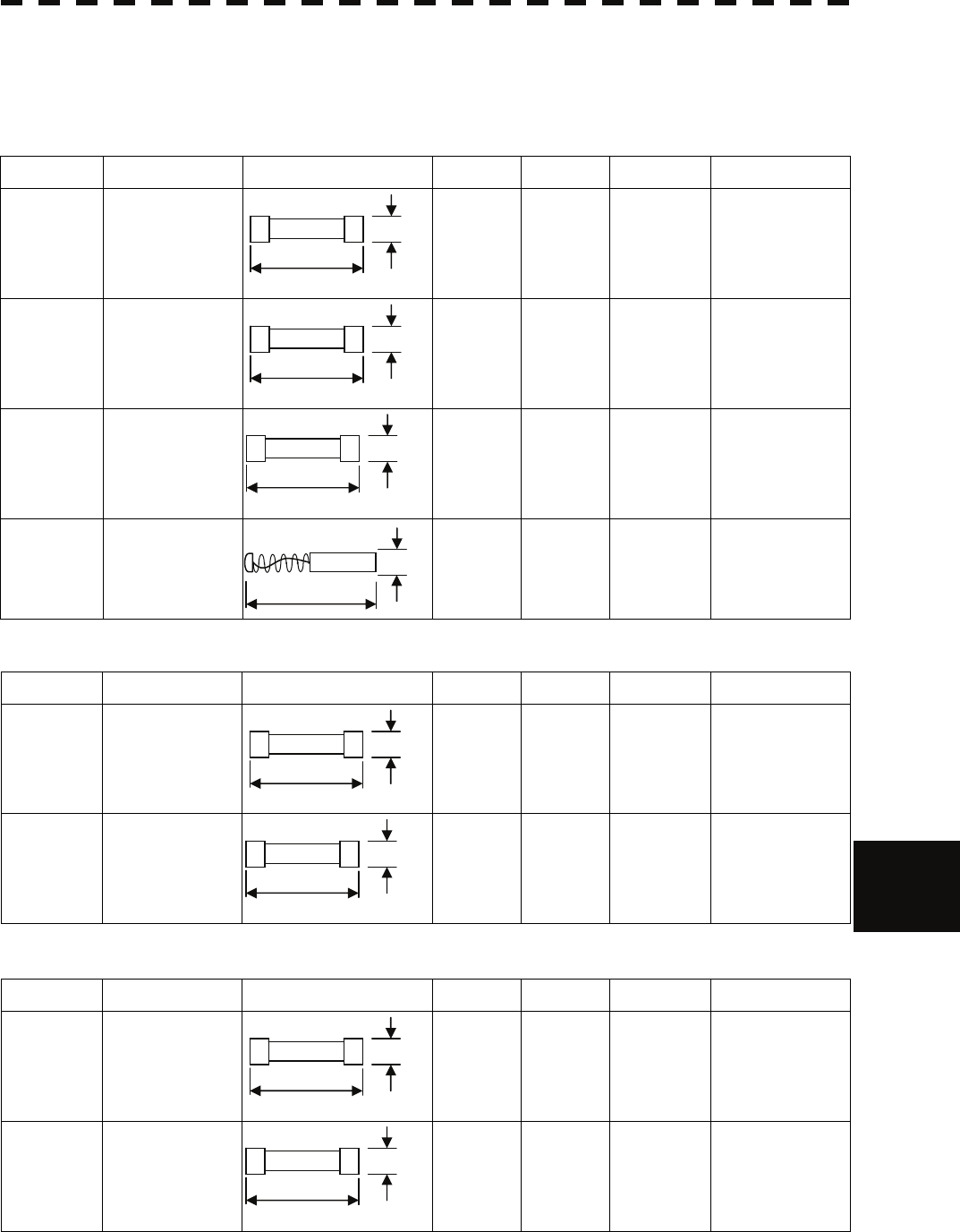
9.2 TROUBLE SHOOTING
9─6
9
y
yyyy
yyyy
9.2.1 Spares
Table 9-7 Spares
7ZXRD0013:Scanner NKE-2062 (6kw)
Name Type/Code Shape (mm) In use Spare Parts No. Location
Fuse
(For
DC12V)
ST4-6.3AN1
(5ZFCA00051)
1 3 F2
Inside
processing unit
Fuse
(For
DC24V)
ST4-3.15AN1
(5ZFCA00047)
1 3 F2
Inside
processing unit
Fuse ST4-5AN1
(5ZFCA00050)
1 3 F3
Inside
processing unit
Motor
brush
54531-01
(BRXP05247)
1 2 – Scanner monitor
7ZXRD0026 : Scanner NKE-2103 (10kw)
Name Type/Code Shape (mm) Number Parts No. Location Application
Fuse ST4-5AN1
(5ZFCA00050)
4 F2
Inside
processing
unit
For the antenna
motor
Fuse ST6-10AN1
(5ZFCA00053)
4 F3
Inside
processing
unit
For the power
supply to
antenna
7ZXRD0015 : Scanner NKE-2254 (25kw)
Name Type/Code Shape (mm) Number Parts No. Location Application
Fuse ST6-10AN1
(5ZFCA00053)
4 F2
Inside
processing
unit
For the antenna
motor
Fuse ST6-10AN1
(5ZFCA00053)
4 F3
Inside
processing
unit
For the power
supply to
antenna
31.8
Φ6.35
31.8
Φ6.35
31.8
Φ6.35
31.8
Φ6.35
31.8
Φ6.35
31.8
Φ6.35
32.0
Φ8.0
31.8
Φ6.35
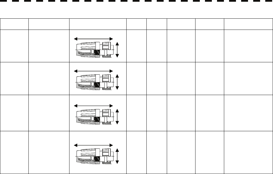
9─7
7ZXRD0027 : Processor unit NDC-1460
Name Type/Cde Shape (mm) In use Spare Parts No. Loccation Application
Connector
LTWBD-
06BFFA-LL7001
(5JCDX00032)
1 1 P3
Inside
processing
unit
Mainly for GPS
connection
Connector
LTWBD-
08BFFA-LL7001
(5JCDX00034)
1 1 P5
Inside
processing
unit
Mainly for
connecting course
equipment such as a
GPS compass
Connector
LTWBD-
07BFFA-LL7001
(5JCD00033)
1 1 P6
Inside
processing
unit
For AIS connection
For connecting
other external
devices when the
AIS is not used
Connector
LTWCD-
14BFFA-LL7001
(5JCDX0052)
1 1 P9
Inside
processing
unit
For connecting
external devices
For acquiring 2-axis
logs, current data,
and wind direction
data
44.0
18.0
44.0
18.0
44.0
18.0
44.0
18.0

9.2 TROUBLE SHOOTING
9─8
9
y
yyyy
yyyy
9.2.2 Special Parts
Table 9-8 Special Parts
[I] JMA-5208/HS
Parts No. Name Type Manufacturer Location Code
V101 Magnetron MSF1422B NJRC Scanner 5VMAA00068
A101 Circulator FCX68 Toshiba Scanner 6AJRD00001
A102 Diode Limiter NJS6930 NJRC Scanner 5EZAA00024
[II] JMA-5212-4/6/4HS/6HS
Parts No. Name Type Manufacturer Location Code
V101 Magnetron MAF1565N NJRC Scanner unit 5VHAA00102
A101/A102 Circulator FCX68R OrientMicrowave Scanner unit 5AJIX00027
A103 Dummy NJC4002 NJRC Scanner unit 5ANDF00001
A104 Filter NJC9952 NJRC Scanner unit 5AWAX00002
A301 Diode Limiter NJS6930 NJRC Scanner unit 5ATBT00006
[III] JMA-5222-7/9
Parts No. Name Type Manufacturer Location Code
V1 Magnetron M1568BS NJRC Scanner unit 5VMAA00106
A101/A102 Circulator NJC3901M NJRC Scanner unit 5AJBV00007
A103 Dummy NJC4002 NJRC Scanner unit 5ANDF00001
A104 Filter NJC9952 NJRC Scanner unit 5AWAX00002
A301 Diode Limiter NJS6930 NJRC Scanner unit 5ATBT00006
9.2.3 Circuit Block to be Repaired
Table 9-9 Circuit Block to be Repaired (JMA-5208)
Location Circuit Block Type Remarks
Scanner Motor with gear CBP-153 DC brush motor (ordinary)
Scanner Modulator CME-323 Excluding Magnetron
Scanner Receiver NRG-226 Including CAE-475-1
Processor Radar processing circuit CDC-1350
Processor DSP circuit (TT) NCA-877A
Processor Power supply terminal circuit unit NBD-866A
Processor AIS processing circuit CDC-1353
Operation panel unit Operation circuit CCK-979
Operation panel unit PS2 connector circuit CQC-1204
Display Brilliance control circuit CCK-970 Brilliance controller
NSK unit Gyro IF circuit CMJ-304E

9─9
Table 9-10 Circuit Block to be Repaired (JMA-5208HS)
Location Circuit Block Type Remarks
Scanner Motor with gear CBP-169 DC brushless motor
Scanner Modulator CME-339 Excluding Magnetron
Scanner Receiver NRG-226 Including CAE-475-1
Processor Radar processing circuit CDC-1350
Processor DSP circuit (TT) NCA-877A
Processor Power supply terminal circuit unit NBD-866A
Processor AIS processing circuit CDC-1353
Operation panel unit Operation circuit CCK-979
Operation panel unit PS2 connector circuit CQC-1204
Display Brilliance control circuit CCK-970 Brilliance controller
NSK unit Gyro IF circuit CMJ-304E
Table 9-11 Circuit Block to be Repaired (JMA-5212-4/6/4HS/6HS)
Location Circuit Block Type Remarks
Scanner Motor with gear 7BDRD0048* DC brushless motor
Scanner Modulation circuit CME-363 Excluding Magnetron
Scanner Receiver NRG-610 Including CAE-529-1
Scanner Power supply circuit CBD-1783
Scanner Encoder CHT71A
Scanner Motor control power circuit CBD-1779
Scanner Performance monitor NJU-85
Processor Radar processing circuit CDC-1350
Processor DSP circuit (TT) NCA-877A
Processor Power supply terminal circuit unit NBD-866A
Processor AIS processing circuit CDC-1353
Operation panel unit Operation circuit CCK-979
Operation panel unit PS2 connector circuit CQC-1204
Display Brilliance control circuit CCK-970 Brilliance controller
NSK unit Gyro IF circuit CMJ-304E
"*" means revision, such as A, B and so on.

9.2 TROUBLE SHOOTING
9─10
9
y
yyyy
yyyy
Table 9-12 Circuit Block to be Repaired (JMA-5222-7/9)
Location Circuit Block Type Remarks
Scanner Motor with gear 7BDRD0044A* DC brushless motor (ordinary
speed)
Scanner Modulator NMA-550 Including CPA-264
Including CMB-404
Excluding Magnetron
Scanner Receiver NRG-162A Including CMA-866A
Scanner Modulation circuit CPA-264
Scanner Power supply circuit CBD-1682A
Scanner T/R control circuit CMC-1205R
Scanner Motor control circuit CBD-1779
Scanner Heater control circuit CHG-216 Optional (AC100V)
Scanner Encoder CHT71A
Scanner Fan 7BFRD0002*
Scanner Performance monitor NJU-85
Processor Radar processing circuit CDC-1350
Processor DSP circuit (TT) NCA-877A
Processor Power supply terminal circuit unit NBD-866A
Processor AIS processing circuit CDC-1353
Operation panel unit Operation circuit CCK-979
Operation panel unit PS2 connector circuit CQC-1204
Display Brilliance control circuit CCK-970 Brilliance controller
NSK unit Gyro IF circuit CMJ-304E
"*" means revision, such as A, B and so on.

9─11
9.3 AFTER-SALES SERVICE
9.3.1 Keeping period of maintenance parts
Keeping period of maintenance parts is ten years from the production is discontinued.
9.3.2 When you Request for Repair
If you suppose the product may be out of order, read the description in Section 9.1 “FAULT
FINDING” and Section 9.2 “TROUBLE SHOOTING” carefully and check the suspected point
again.
If it is still out of order, you are recommended to stop operation of the equipment and consult with
the dealer from whom you purchased the product, or our branch office in your country or district,
the sales department in our main office in Tokyo.
z Repair within the Warranty Period
If any failure occurs in the product during its normal operation in accordance with the
instruction manual, the dealer or JRC will repair free of charge. In case that any failure is
caused due to misuse, faulty operation, negligence or force major such as natural disaster and
fire, the product will be repaired with charges.
z Repair after the Warranty Period
If any defective function of the product is recoverable by repair, the repair of it will be made at
your own charge upon your request.
z Necessary Information for Repair
☆ Product name, model, manufacturing date and serial number
☆ Trouble conditions (as detailed as possible. Refer to “Radar Failure Check List” in page
9-10. )
☆ Name of company/organization, address and telephone number
9.3.3 Recommended Maintenance
The performance of the product may deteriorate due to the secular change of the parts used in it,
though such deterioration depends upon the conditions of operation.
So checkup and maintenance is recommendable for the product in addition to your daily care.
For maintenance, consult with the near-by dealer or our sales department.
Such maintenance will be made with charges.
For further details of after-sale service, contact the JRC Offices.

9.3 AFTER-SALES SERVICE
9─12
9
y
yyyy
yyyy
Radar Failure Check List
When placing an order for repair of the product, it is requested that you could confirm the check items and fill the
results and sent the sheet to our contact.
If there is any unclear items, contact the ship on which the product is installed, and give the correct information on the
product.
Ship name: Phone: Fax:
Radar general model name: JMA- Serial No. :
(Write the full model name correctly)
(1)Check the following items in the order of the number, and circle the applicable answer between YES or NO. If the
item cannot be determined as YES or NO, explain in detail in the item (18), others.
(2)If any of the items (1) to (5) is marked as NO, check the fuse of the product (refer to Section 9.1.2 and 9.2).
(3)Check the items (4) to (17) while the transmission (TX) is ON.
*Functions mentioned in the items (14), (15) and (17) may be optional, answer is not necessary.
No. Check Item Result
(1) Power can be turned on. (The lamp on the Operation unit is lit) YES NO
(2) A few minutes after powering-on, it will become standby status . YES NO
(3) When powering-on (or TX ON), LCD monitor something is lit. YES NO
(4) The antenna rotates at the transmission (TX) ON.
(Check the following items while transmission is ON) YES NO
(5) Current is supplied to the magnetron. (Refer to the instruction manual) YES NO
(6) Turning is enabled. (Check with the range of 6 NM or more) YES NO
(7) Fixed marker is displayed. YES NO
(8) VRM is displayed. YES NO
(9) While noise is displayed while set at SEA and RAIN minimum, GAIN maximum,
IR-OFF and range 48 NM. YES NO
(10) Target reflection echo is displayed. YES NO
(11) Sensitivity of reflection echo is normal. YES NO
(12) EBL is displayed. YES NO
(13) Cursor mark moves. YES NO
*(14) GYRO course can be set and normally displayed. YES NO
*(15) LOG speed can be normally displayed. YES NO
(16) Target tracking function works normally. YES NO
*(17) If equipped with an interswitch, when switching from the straight mode (II) to (X),
the failures (items marked NO) in the above (1) to (16), are switched over to the other
unit. YES NO
(18)Others (Error message, etc. )

9─13

SECTION 10
DISPOSAL
10.1 DISPOSAL OF THE UNIT........................ 10-1
10.2 DISPOSAL OF USED BATTERIES......... 10-2
10.3 DISPOSAL OF USED MAGNETRON ..... 10-3
10.4 ABOUT THE CHINA ROHS..................... 10-4

10─1
10.1 DISPOSAL OF THE UNIT
When disposing of this unit, be sure to follow the local laws and regulations for the place of
disposal.
10.2 DISPOSAL OF USED BATTERIES
10─2
10
yy
yyyy
yyyy
10.2 DISPOSAL OF USED BATTERIES
WARNING
When disposing of used lithium batteries, be sure to insulate the batteries by
taping the ⊕ and ○ terminals.
Otherwise, heat generation, explosion or a fire may occur.
In this unit, Lithium batteries are used for the following parts:
Radar Processing circuit (CDC-1350): BT1 (Maxell: CR2450)
z Do not store used lithium batteries. Dispose of them in accordance with regulations of local
government.
z When disposing of used lithium batteries be sure to insulate the batteries by taping the ⊕ and
○ terminals. For disposal of batteries, be sure to follow the local laws and regulations.
For detail, consult with the dealer you purchased the product our business office, or local
government.
−
−

10─3
10.3 DISPOSAL OF USED MAGNETRON
Magnetron is used in the Scanner (2062/2103/2254)
z When the magnetron is replaced with a new one, return the used magnetron to our dealer or
business office.
For detail, consult with our dealer or business office.

10.3 DISPOSAL OF USED MAGNETRON
10─4
10
yy
yyyy
yyyy
10.4 ABOUT THE CHINA ROHS
形式名(Type): JMA-5200MK2 Series 名称(Name): RADAR
铅 汞 镉 六价铬 多溴联苯 多溴二苯醚
(Pb) (Hg) (Cd) (Cr6+) (PBB) (PBDE)
雷达天线单元
(Scanner Unit) ××○×××
收发信单元
(Transmitter-receiver Unit) ××××××
主船内装置 (Inboard Unit)
・显示装置 (Display Unit)
・键盘装置 (OperationUnit)
・信号处理装置
(RADAR Process Unit)
××××××
外部设备 (Peripherals)
・选择 (Options)
・电线类 (Cables)
・手册 (Documennts)
××××××
有毒有害物质或元素的名称及含量
(Names & Content of toxic and hazardous substances or elements)
(Toxic and Hazardous Substances and Elements)
×:表示该有毒有害物质至少在该部件的某一均质材料中的含量超出SJ/T11363-2006 标准规定的限量要求。
(Indicates that this toxic or hazardous substance contained in at least one of the homogeneous materials
used for this part is above the limit requirement in SJ/T 11363-2006.)
○:表示该有毒有害物质在该部件所有均质材料中的含量均在SJ/T11306-2006 标准规定的限量要求以下。
(Indicates that this toxic, or hazardous substance contained in all of the homogeneous materials for this
part is below the requirement in SJ/T11363-2006.)
部件名称
(Part name)
有毒有害物质或元素

10─5

SECTION 11
SPECIFICATIONS
11.1 JMA-5208/HS TYPE RADAR..........................................................11-1
11.2 JMA-5212-4/6/4HS/6HS TYPE RADAR .........................................11-2
11.3 JMA-5222-7/9 TYPE RADAR..........................................................11-3
11.4 SCANNER (NKE-2062)...................................................................11-4
11.5 SCANNER (NKE-2062HS)..............................................................11-5
11.6 SCANNER (NKE-2103-4/6).............................................................11-6
11.7 SCANNER (NKE-2103-4HS/6HS)...................................................11-7
11.8 SCANNER (NKE-2254-7/9).............................................................11-8
11.9 DISPLAY UNIT (NCD-4380)............................................................11-9
11.10 PROCESSOR UNIT (NDC-1460) ..................................................11-10
11.11 TARGET TRACKING UNIT (NCA-877A)......................................11-12
11.12 AIS UNIT (NQA-2155)...................................................................11-13
11.13 PLOTTER UNIT.............................................................................11-14
11.14 KEYBOARD UNIT (NCE-7699A) ..................................................11-16
11.15 PERFORMANCE MONITOR (NJU-85).........................................11-17
11.16 INPUT ENABLE SIGNAL..............................................................11-17
11.17 OUTPUT ENABLE SIGNAL..........................................................11-18
11.18 STANDARD CONFIGURATION....................................................11-18
11.19 EQUIPMENT DISTANCE BETWEEN OTHER INSTRUMENTS ..11-19
11.20 OTHERS (OPTION).......................................................................11-19

11─1
11.1 JMA-5208/HS TYPE RADAR
(1) Class of Emission P0N
(2) Display Color Raster Scan
(3) Screen 15-inch Color LCD
Effective diameter of radar display, more than 180 mm
(4) Range Scale 0.125, 0.25, 0.5, 0.75, 1.5, 3, 6, 12, 24, 48, 96nm
(5) Range Resolution Less than 25m
(6) Minimum Detective Range Less than 35m
(7) Range Accuracy Less than 1% of the maximum distance of the range scale in use or
less than 15m whichever is larger
(8) Bearing Accuracy Less than 1°
(9) Bearing Indication Relative Motion mode: Head-up/Course-up/North-up
True Motion mode: Course-up/North-up
(10) Ambient Condition According to IEC60945-4
Temperature
Scanner: -25 to +55℃
(Storage Temperature: -25 to +70℃)
Other Unit except Scanner: -15 to +55℃
Relative Humidity 93% at +40℃
Vibration 2 to 13.2Hz, amplitude ±1mm ±10%
13.2 to 100Hz, acceleration 7m/s2
Velocity of the wind 51.5m/s(100kt)
(11) Power Supply Input +24VDC (Display Unit)
+24VDC (Scanner)
* NBA-5111
(12) Power Consumption Approx. 300W (In maximum wind velocity)
(13) Power Supply Voltage +32V/24V/12VDC -10/+30% (JMA-5208)
Fluctuation +24VDC -10/+30% (JMA-5208HS)
(14) Pre-heating Time Approx. Within 1min30sec

11.1 JMA-5212-4/6 TYPE RADAR
11─2
yyy
yyyy
yyyy
11
11.2 JMA-5212-4/6/4HS/6HS TYPE RADAR
(1) Class of emission P0N
(2) Display Color Raster Scan, PPI Method
(3) Screen 15-inch Color LCD
Effective diameter of radar display, more than 180 mm
(4) Range Scale 0.125, 0.25, 0.5, 0.75, 1.5, 3, 6, 12, 24, 48, 96 nm
(5) Range Resolution Less than 30m
(6) Minimum Detective Range Less than 40m
(7) Range Accuracy Less than 1% of the maximum distance of the range scale in use or
less than 15m whichever is larger
(8) Bearing Accuracy Less than 1°
(9) Bearing Indication Relative Motion mode: Head-up/Course-up/North-up
True Motion mode: Course-up/North-up
(10) Ambient Condition According to IEC60945-4
Temperature
Scanner: -25 to +55°C
(Storage Temperature: -25 to +70°C)
Other Unit except Scanner: -15 to +55°C
Relative Humidity 93% at +40°C
Vibration 2 to 13.2Hz, amplitude ±1mm ±10%
13.2 to 100Hz, acceleration 7m/s2
Velocity of the wind 51.5m/s (100kt)
(11) Power Supply Input +24VDC (Display Unit)
+24VDC (Scanner)
∗ Display Unit and Scanner correspond to
100/110/115/220/230/240VAC, 1
ϕ
, 50/60Hz
when use NBA-5111.
(12) Power Consumption Approx. 600W (In maximum wind velocity)
(13) Power Supply Voltage +24VDC –10/+30% (Display Unit)
Fluctuation +24VDC –10/+30% (Scanner Unit)
(14) Pre-heating Time Approx. Within 1min30sec

11─3
11.3 JMA-5222-7/9 TYPE RADAR
(1) Class of emission P0N
(2) Display Color Raster Scan, PPI Method
(3) Screen 15-inch Color LCD
Effective diameter of radar display, more than 180 mm
(4) Range Scale 0.125, 0.25, 0.5, 0.75, 1.5, 3, 6, 12, 24, 48, 96 nm
(5) Range Resolution Less than 30m
(6) Minimum Detective Range Less than 40m
(7) Range Accuracy Less than 1% of the maximum distance of the range scale in use or
less than 15m whichever is larger
(8) Bearing Accuracy Less than 1°
(9) Bearing Indication Relative Motion mode: Head-up/Course-up/North-up
True Motion mode: Course-up/North-up
(10) Ambient Condition According to IEC60945-4
Temperature
Scanner: -25 to +55°C
(Storage Temperature: -25 to +70°C)
Other Unit except Scanner: -15 to +55°C
Relative Humidity 93% at +40°C
Vibration 2 to 13.2Hz, amplitude ±1mm ±10%
13.2 to 100Hz, acceleration 0.7m/s2
Velocity of the wind 51.5m/s (100kt)
(11) Power Supply Input +24VDC (Display Unit)
+24VDC (Scanner)
∗ Display Unit and Scanner correspond to
100/110/115/220/230/240VAC, 1
ϕ
, 50/60Hz
when use NBA-5111.
(12) Power Consumption Approx. 680W (In maximum wind velocity)
(13) Power Supply Voltage +24VDC –10/+30% (Display Unit)
Fluctuation +24VDC –10/+30% (Scanner Unit)
(14) Pre-heating Time Approx. Within 3min

11.2 JMA-5222-7/9 TYPE RADAR
11─4
yyy
yyyy
yyyy
11
11.4 SCANNER (NKE-2062)
(1) Dimensions Height 432mm×Swing Circle 1220mm
(2) Mass Approx. 24kg
(3) Polarization Horizontal Polarization
(4) Directional Characteristic Horizontal Beam Width: 2° (-3dB width)
Vertical Beam Width: 30° (-3dB width)
Sidelobe Level: Below –23dB (within ±10°)
Below –26dB (outside ±10°)
(5) Revolution Approx. 27rpm (Normal)
(6) Peak Power 6 kW
(7) Transmitting Frequency 9410 ±30MHz
(8) Transmitting Tube Magnetron [MSF1422B]
(9) Pulse width/Repetition Frequency
Short Middle Long
0.125NM 0.08μs/2250Hz
0.25NM 0.08μs/2250Hz
0.5NM 0.08μs/2250Hz 0.25μs/1700Hz
0.75NM 0.08μs/2250Hz 0.25μs/1700Hz 0.5μs/1200Hz
1.5NM 0.08μs/2250Hz 0.25μs/1700Hz 0.5μs/1200Hz
3NM 0.25μs/1700Hz 0.5μs/1200Hz 1.0μs/650Hz
6NM 0.25μs/1700Hz 0.5μs/1200Hz 1.0μs/650Hz
12NM 0.25μs/1700Hz 0.5μs/1200Hz 1.0μs/650Hz
24NM 1.0μs/650Hz
48NM 1.0μs/650Hz
96NM 1.0μs/650Hz
(10) Duplexer Circulator + Diode Limiter
(11) Mixer MIC Front End
(12) Intermediate Frequency Amplifier Intermediate Frequency: 60MHz
Band Width: 20MHz(0.08μs)
6MHz(0.25μs,0.5μs)
3MHz(0.8μs, 1μs)
Gain: More than 90dB
Amplifying Characteristics: Logarithmic Amplifier
(13) Overall Noise Figure 6dB(Average)

11─5
11.5 SCANNER (NKE-2062HS)
(1) Dimensions Height 432mm×Swing Circle 1220mm
(2) Mass Approx. 24kg
(3) Polarization Horizontal Polarization
(4) Directional Characteristic Horizontal Beam Width: 2° (-3dB width)
Vertical Beam Width: 30° (-3dB width)
Sidelobe Level: Below –23dB (within ±10°)
Below –26dB (outside ±10°)
(5) Revolution Approx. 48rpm
(6) Peak Power 6 kW
(7) Transmitting Frequency 9410 ±30MHz
(8) Transmitting Tube Magnetron [MSF1422B]
(9) Pulse width/Repetition Frequency
Short Middle Long
0.125NM 0.08μs/2250Hz
0.25NM 0.08μs/2250Hz
0.5NM 0.08μs/2250Hz 0.25μs/1700Hz
0.75NM 0.08μs/2250Hz 0.25μs/1700Hz 0.5μs/1200Hz
1.5NM 0.08μs/2250Hz 0.25μs/1700Hz 0.5μs/1200Hz
3NM 0.25μs/1700Hz 0.5μs/1200Hz 1.0μs/650Hz
6NM 0.25μs/1700Hz 0.5μs/1200Hz 1.0μs/650Hz
12NM 0.25μs/1700Hz 0.5μs/1200Hz 1.0μs/650Hz
24NM 1.0μs/650Hz
48NM 1.0μs/650Hz
96NM 1.0μs/650Hz
(10) Duplexer Circulator + Diode Limiter
(11) Mixer MIC Front End
(12) Intermediate Frequency Amplifier Intermediate Frequency: 60MHz
Band Width: 20MHz(0.08μs)
6MHz(0.25μs,0.5μs)
3MHz(0.8μs, 1μs)
Gain: More than 90dB
Amplifying Characteristics: Logarithmic Amplifier
(13) Overall Noise Figure 6dB(Average)

11.2 JMA-5222-7/9 TYPE RADAR
11─6
11
yyy
yyyy
yyyy
11.6 SCANNER (NKE-2103-4/6)
(1) Dimensions 10kW-4ft: Height 458mm×Swing Circle 1285mm
10kW-6ft: Height 458mm×Swing Circle 1910mm
(2) Mass 10kW-4ft: Approx. 38 kg
10kW-6ft: Approx. 40 kg
(3) Polarization Horizontal Polarization
(4) Directional Characteristic Horizontal Beam Width: 1.8° (4ft, –3dB width)
1.2° (6ft, –3dB width)
Vertical Beam Width: 20° (4/6ft, –3dB width)
Sidelobe Level: Below –26dB (4/6ft, within ±10°)
Below –30dB (4/6ft, outside ±10°)
(5) Revolution Approx. 27rpm (4/6ft, Normal)
(6) Peak Power 10kW ±50%
(7) Transmitting Frequency 9410 ±30MHz
(8) Transmitting Tube Magnetron [MAF1565N]
(9) Pulse width/Repetition Frequency
SP1:0.08μs/2250Hz/Wide
MP1:0.25μs/1700Hz/Middle、MP2:0.5μs/1200Hz/Middle
LP1:0.8μs/750Hz/Narrow、LP2:1.0μs/650Hz/Narrow
0.125NM 0.08μs/2250Hz(SP1)
0.25NM 0.08μs/2250Hz(SP1)
0.5NM 0.08μs/2250Hz(SP1) 0.25μs/1700Hz(MP1)
0.75NM 0.08μs/2250Hz(SP1) 0.25μs/1700Hz(MP1) 0.5μs/1200Hz(MP2)
1.5NM 0.08μs/2250Hz(SP1) 0.25μs/1700Hz(MP1) 0.5μs/1200Hz(MP2)
3NM 0.25μs/1700Hz(MP1) 0.5μs/1200Hz(MP2) 0.8μs/750Hz(LP1)
6NM 0.5μs/1200Hz(MP2) 0.8μs/750Hz(LP1) 1.0μs/650Hz(LP2)
12NM 0.5μs/1200Hz(MP2) 0.8μs/750Hz(LP1) 1.0μs/650Hz(LP2)
24NM 1.0μs/650Hz(LP2)
48NM 1.0μs/650Hz(LP2)
96NM 1.0μs/650Hz(LP2)
(10) Duplexer Circulator + Diode Limiter
(11) Mixer MIC Front End
(12) Intermediate Frequency Amplifier Intermediate Frequency: 60MHz
Band Width: 20MHz(0.08μs)
8MHz(0.25μs,0.5μs)
3MHz(0.8μs, 1μs)
Gain: More than 90dB
Amplifying Characteristics: Logarithmic Amplifier
(13) Overall Noise Figure 7.5dB (Average)

11─7
11.7 SCANNER (NKE-2103-4HS/6HS)
(1) Dimensions 10kW-4ft: Height 458mm×Swing Circle 1285mm
10kW-6ft: Height 458mm×Swing Circle 1910mm
(2) Mass 10kW-4ft: Approx. 38 kg
10kW-6ft: Approx. 40 kg
(3) Polarization Horizontal Polarization
(4) Directional Characteristic Horizontal Beam Width: 1.8° (4ft, –3dB width)
1.2° (6ft, –3dB width)
Vertical Beam Width: 20° (4/6ft, –3dB width)
Sidelobe Level: Below –26dB (4/6ft, within ±10°)
Below –30dB (4/6ft, outside ±10°)
(5) Revolution Approx. 48rpm (4/6ft)
(6) Peak Power 10kW ±50%
(7) Transmitting Frequency 9410 ±30MHz
(8) Transmitting Tube Magnetron [MAF1565N]
(9) Pulse width/Repetition Frequency
SP1:0.08μs/2250Hz/Wide
MP1:0.25μs/1700Hz/Middle、MP2:0.5μs/1200Hz/Middle
LP1:0.8μs/750Hz/Narrow、LP2:1.0μs/650Hz/Narrow
0.125NM 0.08μs/2250Hz(SP1)
0.25NM 0.08μs/2250Hz(SP1)
0.5NM 0.08μs/2250Hz(SP1) 0.25μs/1700Hz(MP1)
0.75NM 0.08μs/2250Hz(SP1) 0.25μs/1700Hz(MP1) 0.5μs/1200Hz(MP2)
1.5NM 0.08μs/2250Hz(SP1) 0.25μs/1700Hz(MP1) 0.5μs/1200Hz(MP2)
3NM 0.25μs/1700Hz(MP1) 0.5μs/1200Hz(MP2) 0.8μs/750Hz(LP1)
6NM 0.5μs/1200Hz(MP2) 0.8μs/750Hz(LP1) 1.0μs/650Hz(LP2)
12NM 0.5μs/1200Hz(MP2) 0.8μs/750Hz(LP1) 1.0μs/650Hz(LP2)
24NM 1.0μs/650Hz(LP2)
48NM 1.0μs/650Hz(LP2)
96NM 1.0μs/650Hz(LP2)
(10) Duplexer Circulator + Diode Limiter
(11) Mixer MIC Front End
(12) Intermediate Frequency Amplifier Intermediate Frequency: 60MHz
Band Width: 20MHz(0.08μs)
8MHz(0.25μs,0.5μs)
3MHz(0.8μs, 1μs)
Gain: More than 90dB
Amplifying Characteristics: Logarithmic Amplifier
(13) Overall Noise Figure 7.5dB (Average)

11.4 SCANNER (NKE-2254-7/9)
11─8
yyy
yyyy
yyyy
11
11.8 SCANNER (NKE-2254-7/9)
(1) Dimensions 25kW-7ft: Height 536mm×Swing Circle 2270mm
25kW-9ft: Height 536mm×Swing Circle 2825mm
(2) Mass 25kW-7ft: Approx. 58 kg
25kW-9ft: Approx. 60 kg
(3) Polarization Horizontal Polarization
(4) Directional Characteristics Horizontal Beam Width: 1.0° (7ft, –3dB width)
0.8° (9ft, –3dB width)
Vertical Beam Width 20° (7/9ft, –3dB width)
Sidelobe Level: Below –26dB
(7/9ft, within ±10°)
Below –30dB
(7/9ft, outside ±10°)
(5) Revolution 24rpm (7/9ft, Normal)
(6) Peak Power 25kW ±50%
(7) Transmitting Frequency 9410 ±30MHz
(8) Transmitting Tube Magnetron [M1568BS]
(9) Pulse Width/Repetition Frequency
SP1:0.07μs/2250Hz/Wide
MP1:0.2μs/2250Hz/Middle、MP2:0.4μs/1400Hz/Middle
LP1:0.8μs/750Hz/Narrow、LP2:1.0μs/650Hz/Narrow、LP3:1.2μs/510Hz/Narrow
0.125NM 0.07μs/2250Hz(SP1)
0.25NM 0.07μs/2250Hz(SP1)
0.5NM 0.07μs/2250Hz(SP1) 0.2μs/2250Hz(MP1)
0.75NM 0.07μs/2250Hz(SP1) 0.2μs/2250Hz(MP1) 0.4μs/1400Hz(MP2)
1.5NM 0.07μs/2250Hz(SP1) 0.2μs/2250Hz(MP1) 0.4μs/1400Hz(MP2)
3NM 0.2μs/2250Hz(MP1) 0.4μs/1400Hz(MP2) 0.8μs/750Hz(LP1)
6NM 0.4μs/1400Hz(MP2) 0.8μs/750Hz(LP1) 1.0μs/650Hz(LP2)
12NM 0.4μs/1400Hz(MP2) 0.8μs/750Hz(LP1) 1.0μs/650Hz(LP2)
24NM 1.0μs/650Hz(LP2)
48NM 1.0μs/650Hz(LP2)
96NM 1.2μs/510Hz(LP3)
(10) Duplexer Circulator + Diode Limiter
(11) Mixer MIC Front End
(12) Intermediate Frequency Amplifier Intermediate Frequency: 60MHz
Band Width: 25MHz(0.07μs)
8MHz(0.2μs, 0.4μs)
3MHz(0.8μs, 1.0μS, 1.2μs)
Gain: More than 90dB
Amplifying Characteristics: Logarithmic Amplifier
(13) Overall Noise Figure 7.5dB (Average)

11─9
11.9 DISPLAY UNIT (NCD-4380)
(1) Structure Desk Top Type
(LCD Monitor Unit/Keyboard Unit/Processor Unit Separation Structure)
(2) Screen 15-inch Color LCD 1024x768 dot (XGA)
Viewing Distance: 1m from the center of Display
(3) Display mode Radar mode
Synthesis mode (Synthesis Radar echo and Coastline)
Plotter mode (Require Plotter Unit (option))
(4) Range Scale 0.125, 0.25, 0.5, 0.75, 1.5, 3, 6, 12, 24, 48, 96nm
(5) Range Marker 0.025, 0.05, 0.1, 0.25, 0.25, 0.5, 1, 2, 4, 8, 16nm
(6) Bearing Indication Rader mode/Synthesis mode
Relative motion: North-up, Course-up, Head-up
True motion: North-up, Course-up
True motion (Plotter mode (Option)): N-up, C-up
(7) Variable Range Maker 2VRM (Digital Display)
VRM Range:0.000 to 97.7nm (0.000 to 181.1km)
(8) Electric Bearing lines 2EBL(Digital Display)
Each EBL can be floating displayed.
EBL unit of Display: 0.1°
EBL Range: 0.000° to 359.9°
Bearing Indication: Relative bearing and True bearing can be switched.
(9) Cursor Target Range, Bearing and Latitude presentation can be possible to move
with trackball.

11.6 PROCESSOR UNIT (NDC-1460)
11─10
yyy
yyyy
yyyy
11
11.10 PROCESSOR UNIT (NDC-1460)
(1) Structure Desk Top Type (Horizontal putting and length putting using
combinedly)
(2) Dimensions Height 125mm×Width 340mm×Depth 347mm
(3) Mass Approx. 4kg
(4) Tune Method AUTO/MANUAL (Bar-graph indicate)
(5) STC (SEA) AUTO/MANUAL
(6) FTC (RAIN) AUTO/MANUAL
(7) Radar Interference Rejection Built-in (The effect can be adjusted by three stages.)
(8) Scan Correlation Function1/2/3, 2 Peak Hold Processing1/2
Automatic change of processing method.
(Target range synchronize/Clutter synchronize)
(9) Bearing Marker 360° in 1° digit.
Relative motion: Fixation
True motion: Rewrite at a position correct in every scan.
(10) Heading Line Electronic
(11) Radar Alarm Invasion, Secession, OFF can be Selected.
With buzzer sound.(Possible to output to External buzzer.)
Ring, operating in rθ space, relative position
∗Automatically acquisition by TT described in Section “TT”
(12) Off Center Within 66% of the radius of any range. (Except 96nm)
Can be operated in all mode in relative motion.
Trail is succeed at Off Center mode.
(13) True motion Unit Built-in (Except 96nm)
(14) True motion reset position 66% of radius of any range.
Possible to manual reset.

11─11
(15) Twice zoom The zoom center is 66% radius of any range. (Except 0.125nm)
(16) Radar trails indication True motion: (Only true motion)
Relative motion:
True motion trails and relative motion trails can be selected.
Trail time length:
15 sec/30 sec/1 min/3 min/6 min/10 min/15 min/30 min/60
min/Continuous/OFF
Arbitrary trail time length can be displayed at any time.
Possible to display time series trail and continuous trail by color
classification.
Built-in Trail thinning process.
Trail function can be use at true motion reset.
When range is changed, Trail function can be use.
Trail function can be use at Off Center. (Relative motion)
When motion indication and bearing indication changed, Trail
function can be use.(Only true motion trails indication.)
(17) Variety of Pulse width SP1/MP1/MP2/LP1/LP2 (NKE-2103)
SP1/MP1/MP2/LP1/LP2/LP3(NKE-2254)
(18) Target enhance 3 stages can be changed.
(19) Correct position When synthesis Radar and Coastline is displayed, position can be
corrected by manually.
(20) Display color Radar echo: 16 stages (Yellow, Green, Amber, Purple, Red)
Radar trails: 16 stages (White, Cyan, Green)
Fixed Maker: Monochrome (Cyan)
VRM1/VRM2/EBL1/EBL2: Monochrome (Cyan)
Character/Bearing Marker: 5 stages (White, Green, Amber, Black,
Red)
Cursor: Monochrome (White)
Heading Line/Vector/TT/AIS: 3 stages (White, Cyan, Green)
Own Ship’s track/Another Ship’s track: 7 stages
Coastline/Isobaths: 16 stages

11.7 TARGET TRACKING UNIT (NCA-877A)
11─12
yyy
yyyy
yyyy
11
11.11 TARGET TRACKING UNIT (NCA-877A)
Radar mode, synthesis mode
1) Acquisition MANUAL/AUTO (by automatic acquisition/activation zone)
2) Tracking 30 target (Automatic tracking)
Maximum tracking range: 32nm (Available all range scale)
3) Display Tracking data: 2 at the same time. (Can be scroll.)
Naming function: Possible to name by the alphabet up to 8 characters
to each target.
The range, bearing, CPA, TCPA, true course, true speed, BCR, BCT of
target can be displayed.
(When naming is displayed, BCR/BCT can’t be displayed.)
Vector display: True/Relative
Past position
4) Alarm Automatic acquisition/activation zone
Danger ship: CPA limit 0.1 to 9.9 nm, TCPA limit 1 to 99 min
Synthesis mode
5) Another ship track 20 targets. 1500 point per one target can be displayed.
(including AIS targets)
Display color: 7 colors
(The display color of each target can be set.)
(The display color of all targets can be set by the batch. In this case, the
display color is one color.)
Interval of save: 3/5/10/30 sec, 1/3/5/10/130/160 min, 1/3/5/10 nm
Possible to storage in memory card (Option).

11─13
11.12 AIS UNIT (NQA-2155)
Radar mode, synthesis mode
1) Activation 30 target
MANUAL/AUTO (by automatic activation/activation zone)
2) Display 130 target (sleeping target and activated target)
AIS data: 1 at the same time. (simple display)
Vector display: True/Relative
Past position
The message can be displayed. (broadcast message, addressed message)
Target information in numerical values: Select one of the following four
screens:
・Navigation information screen
True bearing, Distance, Course, Speed, CPA, TCPA,
Heading bearing, Turning speed
・Destination and position information screen
Destination, Estimated time of arrival, Latitude and longitude,
Position fixing equipment, RAIM, Position fixing accuracy
・Ship information screen
Ship name, Call sign, MMSI, IMO number, Navigation status
・AtoN information screen
AtoN class, AtoN type
3) Alarm Automatic activation/activation zone
Danger ship: CPA limit 0.1 to 9.9 nm, TCPA limit 1 to 99 min
Synthesis mode
4) Another ship track 20 targets. 1500 point per one target can be displayed. (including TTs)
Display color: 7 colors
(The display color of each target can be set.)
(The display color of all targets can be set by the batch. In this case, the
display color is one color.)
Interval of save: 3/5/10/30 sec, 1/3/5/10/130/160 min, 1/3/5/10 nm
Possible to storage in memory card (Option).

11.9 PLOTTER UNIT
11─14
yyy
yyyy
yyyy
11
11.13 PLOTTER UNIT
(1) Plotter (Normal) (Synthesis mode)
Projection: Mercator projection (Latitude 70 degree or less.)
Scale: Radar synchronize range scale
Own ship trail: Color of 1 stage.
Interval of storage 3/5/10/30 sec, 1/3/5/10/30/60 min or
every 0.1/0.2/0.3/0.5/1/3/5/10 nm and OFF
Cursor mark : Storage Capacity 7,000 point
Coastline data : Coastline ROM Card (Option) (ERC, JRC, C-Map NT+)
One selected isobath can be displayed.
Painting out: ON/OFF can be selected.
(2) Plotter (Option NDB-44) (Synthesis mode)
Projection: Mercator projection (Latitude 70 degree or less.)
Scale: Synchronize range scale
Own ship trail: Color of 7 stages.
Interval of storage: 3/5/10/30 sec, 1/3/5/10/30/60 min or
every 0.1/0.2/0.3/0.5/1/3/5/10 nm and OFF
Storage capacity of own ship trail: 7,000 point
Cursor mark: Color of 7 stages
Storage capacity of cursor mark: 20,000 point
Variety of cursor Mark: 19
Event mark: Color of 7 stages
Storage capacity of event mark: Include in cursor mark
Variety of event mark: 3 kinds, (Two kinds can be switched.
/8 form to selection.)
Variety of external event mark: One kind, Monochrome
Line: Color of 7 stage
Storage capacity of line: Include in cursor mark
Variety of line: Solid line, broken line, alternate long and
short dash line
Coast line data: Coast line ROM card (Option) (ERC, JRC, C-Map NT+)
Selected one isoline can be displayed.
Painting out: ON/OFF can be selected.
External memory: Memory card (Option)
Destination and sea route: Destination can be set up to 99 point.
Information of destination: Azimuth, distance and the time
to required destination.
Setting of sea route: 10 sea routes. (10 destination for one
sea route can be set.)
Alarm of sea route: Destination, Secession, Invetion,
Secession
Position compensation: Radar display synchronize range scale coast line by manual.

11─15
(3) Plotter (Option NDB-44) (Synthesis mode)
Projection: Mercator projection (Latitude 85 degree or less.)
Scale: 1/1,000 to 1/10,000,000 are continuously selected.
10 stage can be changed (Preset can be used)
Own ship trail: Color of 7 stages.
Interval of storage: 3/5/10/30 sec, 1/3/5/10/30/60 min or
every 0.1/0.2/0.3/0.5/1/3/5/10 nm and OFF
Storage capacity of own ship trail: 7,000 point
Cursor mark: Color of 7 stages
Storage capacity of cursor mark: 20,000 point
Variety of cursor Mark: 19
Event mark: Color of 7 stages
Storage capacity of event mark: Include in cursor mark
Variety of event mark: 3 kinds, (Two kinds can be switched.
/8 form to selection.)
Variety of external event mark: One kind, Monochrome
Line: Color of 7 stage
Storage capacity of line: Include in cursor mark
Variety of line: Solid line, broken line, alternate long and
short dash line
Coast line data: Coast line ROM card (Option)(ERC, JRC, C-Map NT+)
Selected one isoline can be displayed.
Painting out: ON/OFF can be selected.
External memory: Memory card (Option)
Own ship trail, another ship trail, cursor mark, event mark,
line, destination, sea route can be memorized.
Destination and sea route: Destination can be set up to 99 point.
Information of destination: Azimuth, distance and the time
to required destination.
Setting of sea route: 10 sea routes. (10 destination for one
sea route can be set.)
Alarm of sea route: Destination, Secession, Invetion,
Secession

11.10 KEYBOARD UNIT (NCE-7699A)
11─16
yyy
yyyy
yyyy
11
11.14 KEYBOARD UNIT (NCE-7699A)
(1) Structure Structure of keyboard unit is separate from processor unit.
Desk-Top type
Correspond Flush mount
(2) Switch Gain (Transmit pulse width can be changed by PUSH-SW.)
SEA (AUTO/MANU can be changed by PUSH-SW.)
RAIN (AUTO/MANU can be changed by PUSH-SW.)
MULTI (Adjustment item can be changed by PUSH-SW)
EBL (Floating EBL ON/OFF can be changed by PUSH-SW.)
VRM
Trackball
(3) Operation switch
STBY/OFF (Standby/Power off): Stop transmit, Power off.
TX/OFF (Transmit start/Power off): Start transmit, Power off
PANEL(Brightness of keyboard adjustment): Brightness of keyboard switch adjust.
ALARM ACK(Stop Alarm): Acknowledge and stop alarm.
EBL1(EBL1): Selection display and non-display of EBL1.
EBL2(EBL2): Selection display and non-display of EBL2.
VRM1(VRM1): Selection display and non-display of VRM1.
VRM2(VRM2): Selection display and non-display of VRM2.
RANGE+(Increase display range): Increase display range.
RANGE-(decrease display range): decrease display range.
ACQ(acquisition): TT target acquisition
TGT DATA(Numeric display): Numeric display of tracking target.
TGT CNCL(Release of selection): Release of selection of tracking target.
MOB(Marker): Turning on and release marker.
ENT(Enter): Left side button of trackball.
CLR/INFO(Release/Information): Right side of trackball.
MAP(Display mode): Selection display and non-display of MAP(NAV
LINE, etc…).
Selection of Rader, Synthesis and Plotter mode.
AZI MODE(Display azimuth): Selection of North-up, Course-Up, Head-Up.
TM/RM(True/Relative Motion): Selection true motion, relative motion.
RR/HL(Fixed ring/Heading Line): Selection display and non-display of fixed ring and
heading line.
OFF CENT(Off Center): Off center operation
AZ (Guard zone alarm): Setting and release of automatic acquisition/activate
zone.
VECT T/R (True/Relative motion vector): Selection of true motion and relative motion of
vector.
TRAILS (Trails): Selection display and non-display of trails.
Day/Night(Brightness of screen switch): Selection of screen arrangement of color.
FUNC(Function): Selection of signal processing.
USER KEY1(User key1): User assignment key1.
USER KEY2(User key2): User assignment key2.
RADAR MENU(Radar menu): Rader menu.
MARK(MARK): Selection display and non-display of mark.
TT MENU(TT menu): TT menu.

11─17
11.15 PERFORMANCE MONITOR (NJU-85)
(1) Dimensions Height 130mm×Width 149mm×Depth 70mm
(2) Mass Approx. 1.2kg
(3) Operating frequency 9410 ±30MHz
11.16 INPUT ENABLE SIGNAL
(1) Navigation equipment: IEC61162-1/2
Receive port NAV1/NAV2/GPS port
Receive capability sentence.
Longitude/Latitude: GGA>RMC>RMA>GNS/GLL
Waypoint: RMB>BWC(BWR)
COG/SOG: RMC>RMA>VTG
SPEED: VBW
Day/Time information: ZDA
Alarm acknowledge: ACK
Rate of Turn : ROT
Rudder : RSA
(2) Bearing signal: GYRO-SYNC: 360X, 180X, 90X, 30X. (Require optional NSK
unit NCT-4106A)
GYRO-STEP: 360X, 180X, 90X, 30X. (Require optional NSK
unit NCT-4106A)
JRC-NSK format (JLR-10, JLR20/30)
IEC61162-2 38400bps: THS>HDT>HDG>HDM>VHW
(over 40Hz)
IEC61162-1: THS>HDT>HDG>HDM>VHW
∗ Can’t be use for target tracking.
(3) Speed signal: LOG-SYNC: 360X, 180X,90X, 30X. (Require optional NSK
unit NCT-4106A)
LOG-PULSE: 800, 400, 200, 100. (Require optional NSK unit
NCT-4106A)
(4) External event mark: Contact input by way of terminal board.
(5) Depth: DPT>DBK>DBT>DBS, JRC format
(6) Water temperature: MTW, JRC format
(7) Tendency: CUR, JRC format
(8) Direction of wind, velocity of wind: MWV, MWD
(9) AIS: IEC61162-2
VDM, VDO (Require optional AIS process unit NQA-2155)
Note: The Speed measuring accuracy of speed sensor shall confirm to IMO Resolution MSC.96(72).
The measuring accuracy of GPS shall confirm to IMO Resolution MSC.112(73).

11.13 OUTPUT ENABLE SIGNAL
11─18
yyy
yyyy
yyyy
11
11.17 OUTPUT ENABLE SIGNAL
(1) Slave video Radar video: TIY, VD, BP(2048p), BZ (Option)
(2) Navigation information IEC61162-1/2
Radar system data: RSD
Own ship data: OSD
Tracking target data: TTM, TLL, TTD, TLB
Alarm: ALR
Auto pilot: APB
Bearing of destination: BOD
Latitude/Longitude data : GGA, GLL, RMC
Waypoint data : RMB, BWC
COG/SOG data : VTG
Cross track error: XTE
Heading data: HDT, THS
(3) Failure of RADAR J5 (NSK/COMPASS connector) ⑥ALM+, ⑦ALM-
or External alarm NCT-4106A(TB40) option
Refer to 3.21 and 3.22 in Installation manual.
(4) External monitor Multi scan monitor, Analog RGB, HD15pin Connector (Option)
11.18 STANDARD CONFIGURATION
(1) Scanner 1
(2) Display unit 1 (Processor unit, LCD unit, Keyboard unit)
(3) Power cable CFQ-5436-5 (5m)
(4) Equipment reserve parts 1
(5) Instruction manual 1 (Japanese or English)
Note: An equipment cable is optional.
Purchase an equipment cable of desired length.

11─19
11.19 EQUIPMENT DISTANCE BETWEEN
OTHER INSTRUMENTS
Maximum
(1) LCD monitor to processor unit 5m
(2) Keyboard unit to processor unit 5m
(3) Scanner to display unit (10/25kw) 65m
(4) Scanner to display unit (6kw NKE-2062 DC12V) 20m
(5) Scanner to display unit (6kw NKE-2062 DC32V/24V) 30m
(6) Scanner to display unit (6kw NKE-2062HS DC24V) 30m
11.20 OTHERS (OPTION)
• Equipment cable 6/10/25 kW type (connectors on both ends)
Cable length:
10m CFQ-6912-10/15m CFQ-6912-15
20m CFQ-6912-20/30m CFQ-6912-30
40m CFQ-6912-40/50m CFQ-6912-50
65m CFQ-6912-65
• TT unit NCA-877A
• NSK unit NCT-4106A
• AIS unit NQA-2155
• Plotter unit NDB-44
• X band performance monitor NJU-85
• Display stand MPBX42944
• Horizontal sun visor for NWZ-164 MPOL30369
• Vertical sun visor for NWZ-164 MPOL30370
• Simple ISW cable CFQ-5251 (5 m)
• Sub-monitor lead cable CFQ-5350 (7ZCRD1153)
• ISW/sub-operation unit lead cable CFQ-5351 (7ZCRD1152)
• NMEA lead cable CFQ-5352 (7ZCRD1212)
• NMEA lead cable 2 CFQ-5462 (2CH pair for transmission and receive)
• Cable between connected NMEA units CFQ-6560 (10 m)
• JLR-10 connection cable CFQ-6934 (10 m)
• JLR-20/30 connection cable CFQ-5469
• Keyboard extension cable CFQ-6999 (10 m)
• NDW-51 connection cable CFQ-7082
• Coast line ROM card
• Memory card
• Rectifier unit NBA-5111

APPENDIX
FIGURE 1 JMA-5208/HS, JMA-5212-4/6/4HS/6HS, JMA-5222-7/9 BLOCK DIAGRAM
FIGURE 2 JMA-5208/HS INTER-CONNECTION DIAGRAM
FIGURE 3 JMA-5212-4/6/4HS/6HS INTER-CONNECTION DIAGRAM
FIGURE 4 JMA-5222-7/9 INTER-CONNECTION DIAGRAM
FIGURE 5 PRIMARY POWER SUPPLY DIAGRAM,
TYPE JMA-5208/HS, JMA-5212-4/6/4HS/6HS, JMA-5222-7/9
FIGURE 6 PROCESSOR UNIT, NDC-1460 INTER-CONNECTION DIAGRAM
FIGURE 7 KEY-BOARD UNIT, NCE-7699A INTER-CONNECTION DIAGRAM
FIGURE 8 NKE-2062 SCANNER UNIT INTERCONNECTION DIAGRAM
FIGURE 9 NKE-2062HS SCANNER UNIT INTERCONNECTION DIAGRAM
FIGURE 10 NKE-2103 SCANNER UNIT INTERCONNECTION DIAGRAM
FIGURE 11 NKE-2254 INTERCONNECTION DIAGRAM OF SCANNER UNIT
FIGURE 12 JMA-5200MK2 ON-SCREEN CONTROLS
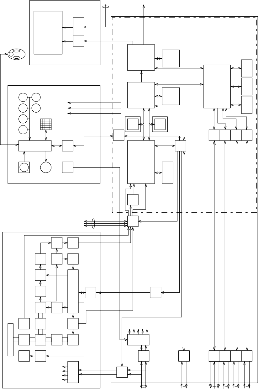
Figure 1 JMA-5208/HS, JMA-5212-4/6/4HS/6HS, JMA-5222-7/9 Block Diagram
Radiater
Motor Rotary
Joint
BW Control
Bearing
Encoder
Motor
Cont. Circula
tor Diode
Limiter
LO Control
MIC
RS485
I/F
BPF LOG
AMP
Magne
tron DAC LOG
AMP MIX
Tx
Cont. CPU
Scanner NKE-2062/2103/2254
TUNE
indicator bufferPower supply
IF AMP
TI VD BP/BZ
+15V
+8V
HV
-7V
Pulse
Trans
VD
BP/BZ
TI
Relay
NMEA
I/F
RS485
I/F
Power supply
Filter
P12V
+12V
-12V
+5V
+3.3V
DC24V
-10%
+30%
GYRO LOG
/GPS Compass
/Compass
NMEA
I/F
NMEA
I/F
RS232C
I/F
NMEA
I/F
GPS Rear
connector
PC
NAV1/AIS
NAV2
+12V
RADAR PROCESS UNIT NDC-1460
ISW
SEL ADC
Main PCB
PWR
SW
DSP
radar
DSP
ARPA
BP/BZ
VD
TI
Radar draw ASIC
Scan convert
Scan correlation
Trail process
Key Board NCE-7699A
RS422
I/F
RS422
I/F
TrackBall
Buzer CPU Key Matrix
MULTI
Frame
Memory
Radar echo
Radar trails
Sub
CPU
Encoder
RAIN SEA
EBL
PS/2
GAIN
VRM
Trackball
(option)
15 inch LCD
P12V
+12V
+5V
Display NWZ-164
Analog RGB
option
Graphics ASIC
MAP draw
Graphics draw
Frame
Memory
MAP
Graphics
LDI
I/F
RGB
Power
supply
sweep memory
Signal proc ASIC
STC/FTC/CFAR
IR/AVE/GZalarm
DC24V
-10%
+30%
External
Display
SIO
SIO
SIO
SIO
32bit bus
32bit bus
Main CPU
Communication
User I/F
Main Control
SDRAM
work FROM
program SRAM
Back up
option
MONITOR UNIT NWZ-164
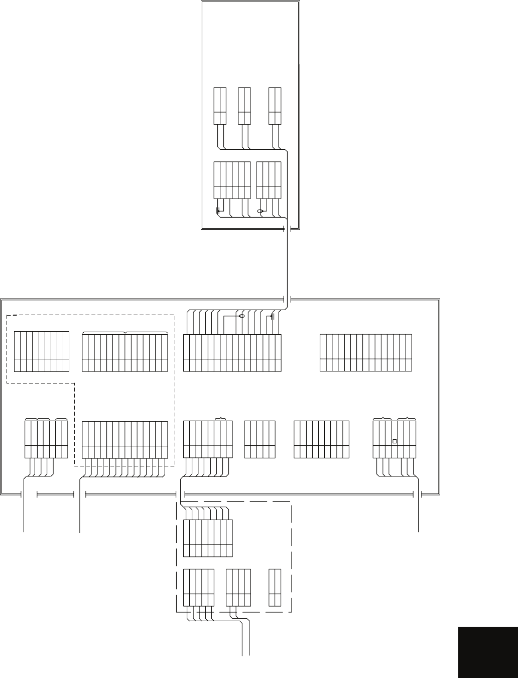
APPENDIX
11/R1
22/S1
33/S2
4S3
55/R2
TB10
GYRO SYNC/STEP
TB20
1LOGP+
2LOGP-
3LOGS+
4LOGS-
LOG SYNC/PULSE
TB40
1BUZZ+
2BUZZ-
BUZZER OUTPUT
250V-MPYCYS-7
250V-DPYCYS-1.5
LOG(200P)
GYRO
1 NSKTXD-
2 NSKTXD+
3 NSKRXD+
4 NSKRXD-
5GND
6ALM+
7ALM-
8+5V
NCT-4106A NSK UNIT
(OPTION)
SUB KEYBOARD
AIS 250V-TTYCS-4
1 NMEA RXD+
2 NMEA RXD-
3 NMEA TXD+
4 NMEA TXD-
5GND
6 EVENT+
7 EVENT-
J6
RS-422 PORT
OUTPUT
INPUT
EVENT INPUT
1+
1-
2+
2-
3+, 3-
NCD-4380 DISPLAY UNIT
CBD-1702A I/O POWER SUPPLY BOARD
1 P12V
2 P12VE
3FG
4PS
5CONT1
6CONT2
7KEYTXD-
8KEYTXD+
9 KEYRXD+
10 KEYRXD-
11 +12V
12 +12V
13 GND
14 GND
J9 (J5007) option
to GPS
CFQ-6998
1 NSKTXD-
2 NSKTXD+
3 NSKRXD+
4 NSKRXD-
5GND
6ALM+
7ALM-
8+5V
to JLR-10 / 20 / 30 / NCT-4106A
J5
1+12V
J3
2GND
3 NAVCOM
4 GPSRXD+
5 GPSTXD+
1NC
J8
RS232C PORT
2 PCRXD
3PCTXD
4NC
5GND
6NC
7 PCRTS
8 PCCTS
9NC
11A
J1
POWER INPUT
21A
31A
52A
62A
72A
4
+
-
RED
RED
RED
BLK
BLK
BLK
SHIPS MAINS
DC24V
300Wmax
CFQ-5436-5
(5m JRC SUPPLY)
1RED
(J4406)
2GRN
3BLU
4NC
5NC
6RED-GND
7 GRN-GND
8BLU-GND
9NC
10 HSYNC-GND
11 VSYNC-GND
12 NC
13 HSYNC
14 VSYNC
15 NC
SLAVE RGB OUTPUT
1M-
J2
SUB KEY-BOARD
2M-
3M+
4M+
52A
6GND
7VDE
8+12V
91A
10 VD
11 MTR+
12 BZ
13 MTR-
14 TRGE
15 TRG
16 BP
BLU.T/GRY.T
PUR.T/BRN.T
WHT.T/ORN.T
RED.T/GRN.T
BLK.T/SKY.T
BLK
YEL.T/PNK.T
YEL
GRN
WHT
ORN
1 EVDO
2 EVDOE
3FG
4ETRGO
5 EBPO
6 EBZO
7ETRGOE
8 EVDI
9 EVDIE
10 ETRGI
11 +12V
12 EBPI
13 EBZI
14 ETRGIE
J9 (J5009) option
SIMPLYFIED ISW
OUTPUT
INPUT
to NMEA equipments
19-CORES CABLE
CFQ-6912-20/30
(JRC SUPPLY)
BUZZER OUTPUT
1 NAV2 RXD-
2 NAV2 RXD+
3
4 NAV2 RXD+
5NAV2 TXD-
6 RS232C RXD-
7 RS232C RXD+
8 RS232C TXD+
9 RS232C TXD-
J9 (J5012)
NKE-2062 SCANNER UNIT
ORN
GRN
BLK
YEL
WHT
1 TRIG+
J1
2 TRIG-
3 BP+
4 BP-
5BZ+
6BZ-
1VD+
J2
2VD-
3MTR+
4MTR-
BLK.T/SKY.T
YEL.T/PNK.T
BLU.T/GRY.T
WHT.T/ORN.T
PRL.T/BRN.T
RED.T/GRN.T
12A
J3
21A
12A
J4
21A
12A
J5
21A
Figure 2 JMA-5208/HS Inter-connection Diagram
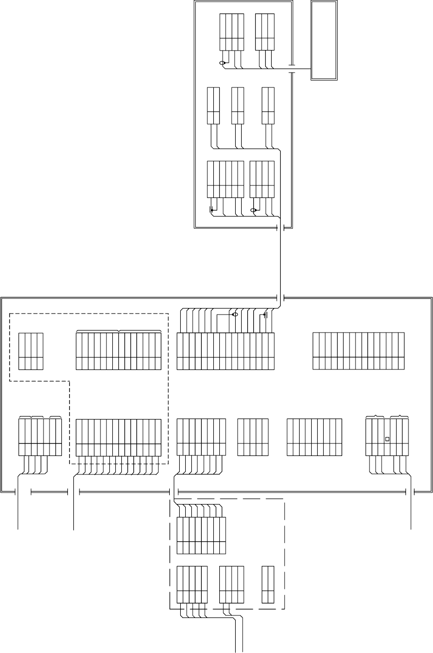
Figure 3 JMA-5212-4/6/4HS/6HS Inter-connection Diagram
11/R1
22/S1
33/S2
4S3
55/R2
TB10
GYRO SYNC/STEP
TB20
1 LOGP+
2 LOGP-
3 LOGS+
4 LOGS-
LOG SYNC/PULSE
TB40
1BUZZ+
2BUZZ-
BUZZER OUTPUT
250V-MPYCYS-7
250V-DPYCYS-1.5
LOG(200P)
GYRO
1NSKTXD-
2NSKTXD+
3NSKRXD+
4NSKRXD-
5GND
6ALM+
7ALM-
8+5V
NCT-4106A NSK UNIT
(OPTION)
SUB KEYBOARD
AIS 250V-TTYCS-4
1 NMEA RXD+
2 NMEA RXD-
3 NMEA TXD+
4 NMEA TXD-
5GND
6 EVENT+
7 EVENT-
J6
RS-422 PORT
OUTPUT
INPUT
EVENT INPUT
1+
1-
2+
2-
3+, 3-
NCD-4380 DISPLAY UNIT
CBD-1702A I/O POWER SUPPLY BOARD
1P12V
2P12VE
3FG
4PS
5CONT1
6CONT2
7 KEYTXD-
8 KEYTXD+
9 KEYRXD+
10 KEYRXD-
11 +12V
12 +12V
13 GND
14 GND
J9 (J5007)
to GPS
CFQ-6998
1NSKTXD-
2NSKTXD+
3NSKRXD+
4NSKRXD-
5GND
6ALM+
7ALM-
8+5V
to JLR-10 / NCT-4106
J5
1+12V
J3
2GND
3NAVCOM
4 GPSRXD+
5 GPSTXD+
1NC
J8
RS232C PORT
2 PCRXD
3PCTXD
4NC
5GND
6NC
7 PCRTS
8 PCCTS
9NC
11A
J1
POWER INPUT
21A
31A
52A
62A
72A
4
+
-
RED
RED
RED
BLK
BLK
BLK
SHIPS MAINS
DC24V
300Wmax
CFQ-5436-5
(5m JRC SUPPLY)
1RED
CFQ-5350
2GRN
3BLU
4NC
5NC
6RED-GND
7GRN-GND
8BLU-GND
9NC
10 HSYNC-GND
11 VSYNC-GND
12 NC
13 HSYNC
14 VSYNC
15 NC
SLAVE RGB OUTPUT
1M-
J2
SUB KEY-BOARD
2M-
3M+
4M+
52A
6GND
7VDE
8+12V
91A
10 VD
11 MTR+
12 BZ
13 MTR-
14 TRGE
15 TRG
16 BP
BLU.T/GRY.T
PUR.T/BRN.T
WHT.T/ORN.T
RED.T/GRN.T
BLK.T/SKY.T
BLK
YEL.T/PNK.T
YEL
GRN
WHT
ORN
1 EVDO
2 EVDOE
3FG
4ETRGO
5 EBPO
6 EBZO
7ETRGOE
8 EVDI
9 EVDIE
10 ETRGI
11 +12V
12 EBPI
13 EBZI
14 ETRGIE
J9 (J5008)
SIMPLYFIED ISW
OUTPUT
INPUT
1 NMEARXD+
J9 (TB2J)
2 NMEARXD-
3NMEATXD+
4NMEATXD-
to NMEA equipments
19-CORES CABLE
CFQ-6912-20/30
(JRC SUPPLY)
NKE-2103-4/6 SCANNER UNIT
ORN
GRN
BLK
YEL
WHT
1ETIY
J1
2AGND
3EXBP
4AGND
5EXBZ
6AGND
9VD
J2
10 VDE
11 MTR+
12 MTR-
BLK.T/SKY.T
YEL.T/PNK.T
BLU.T/GRY.T
WHT.T/ORN.T
PUR.T/BRN.T
RED.T/GRN.T
12A
J3
21A
12A
J4
21A
12A
J5
21A
RED
BLK
BLU
WHT
BRN
BLK
WHT
1LVR
J82
2PMS
3E
1PTI
J81
2PTE
3LVR
4PMS
To PM
PM UNIT must be fitted on ships
compliant to IMO.
NJU-85 PM UNIT (OPTION)
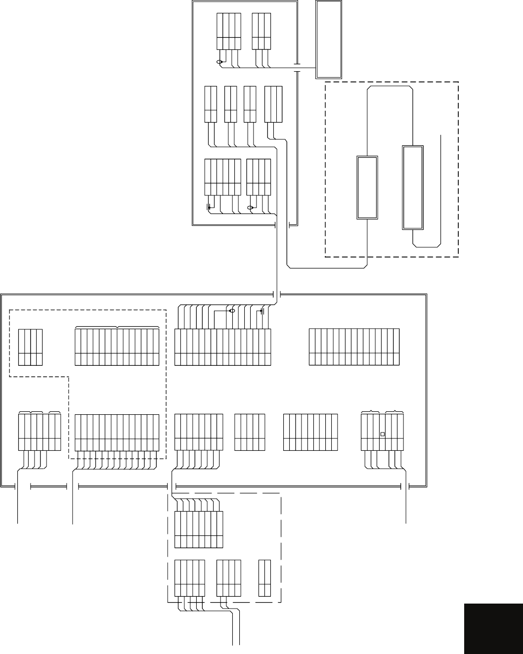
APPENDIX
Figure 4 JMA-5222-7/9 Inter-connection Diagram
11/R1
22/S1
33/S2
4S3
55/R2
TB10
GYRO SYNC/STEP
TB20
1LOGP+
2LOGP-
3LOGS+
4LOGS-
LOG SYNC/PULSE
TB40
1BUZZ+
2BUZZ-
BUZZER OUTPUT
250V-MPYCYS-7
250V-DPYCYS-1.5
LOG(200P)
GYRO
1NSKTXD-
2NSKTXD+
3 NSKRXD+
4 NSKRXD-
5GND
6ALM+
7ALM-
8+5V
NCT-4106A NSK UNIT
(OPTION)
SUB KEYBOARD
AIS 250V-TTYCS-4
1NMEA RXD+
2NMEA RXD-
3NMEA TXD+
4NMEA TXD-
5GND
6EVENT+
7EVENT-
J6
RS-422 PORT
OUTPUT
INPUT
EVENT INPUT
1+
1-
2+
2-
3+, 3-
NCD-4380 DISPLAY UNIT
CBD-1702A I/O POWER SUPPLY BOARD
1P12V
2P12VE
3FG
4PS
5CONT1
6CONT2
7KEYTXD-
8KEYTXD+
9KEYRXD+
10 KEYRXD-
11 +12V
12 +12V
13 GND
14 GND
J9 (J5007)
to GPS
CFQ-6998
1 NSKTXD-
2 NSKTXD+
3 NSKRXD+
4 NSKRXD-
5GND
6ALM+
7ALM-
8+5V
to JLR-10 / NCT-4106
J5
1+12V
J3
2GND
3 NAVCOM
4 GPSRXD+
5GPSTXD+
1NC
J8
RS232C PORT
2 PCRXD
3PCTXD
4NC
5GND
6NC
7 PCRTS
8 PCCTS
9NC
11A
J1
POWER INPUT
21A
31A
52A
62A
72A
4
+
-
RED
RED
RED
BLK
BLK
BLK
SHIPS MAINS
DC24V
300Wmax
CFQ-5436-5
(5m JRC SUPPLY)
1RED
CFQ-5350
2GRN
3BLU
4NC
5NC
6RED-GND
7GRN-GND
8BLU-GND
9NC
10 HSYNC-GND
11 VSYNC-GND
12 NC
13 HSYNC
14 VSYNC
15 NC
SLAVE RGB OUTPUT
1M-
J2
SUB KEY-BOARD
2M-
3M+
4M+
52A
6GND
7VDE
8+12V
91A
10 VD
11 MTR+
12 BZ
13 MTR-
14 TRGE
15 TRG
16 BP
BLU.T/GRY.T
PUR.T/BRN.T
WHT.T/ORN.T
RED.T/GRN.T
BLK.T/SKY.T
BLK
YEL.T/PNK.T
YEL
GRN
WHT
ORN
1 EVDO
2 EVDOE
3FG
4ETRGO
5 EBPO
6 EBZO
7 ETRGOE
8 EVDI
9 EVDIE
10 ETRGI
11 +12V
12 EBPI
13 EBZI
14 ETRGIE
J9 (J5008)
SIMPLYFIED ISW
OUTPUT
INPUT
1NMEARXD+
J9 (TB2J)
2NMEARXD-
3 NMEATXD+
4 NMEATXD-
to NMEA equipments
19-CORES CABLE
CFQ-6912-20/30
(JRC SUPPLY)
NKE-2254-7/9 SCANNER UNIT
ORN
GRN
BLK
YEL
WHT
1ETIY
J1
2AGND
3 EXBP
4AGND
5 EXBZ
6AGND
9VD
J2
10 VDE
11 MTR+
12 MTR-
BLK.T/SKY.T
YEL.T/PNK.T
BLU.T/GRY.T
WHT.T/ORN.T
PUR.T/BRN.T
RED.T/GRN.T
12A
J3
21A
12A
J4
21A
12A
J5
21A
RED
BLK
BLU
WHT
BRN
BLK
WHT
1LVR
J82
2PMS
3E
1PTI
J81
2PTE
3LVR
4PMS
To PM
NJU-85 PM UNIT (OPTION)
NOTE:
Performance monitor must be fitted
on ships compliant to IMO.
U
V
UTH
TB105
CIRCUIT BREAKER 5A
(SHIPYARD SUPPLY )
0.6/1kV-DPYCYS-1.5
0.6/1kV-DPYC-1.5
AC100V 50/60Hz
1ٛ 100W
NBL-175
STEP-DOWN TRANSFORMER
SHIP’S MAIN
AC220/230/240V
50/60Hz 1ٛ
0.6/1kV-DPYC-1.5
“D” HEATER OPTION
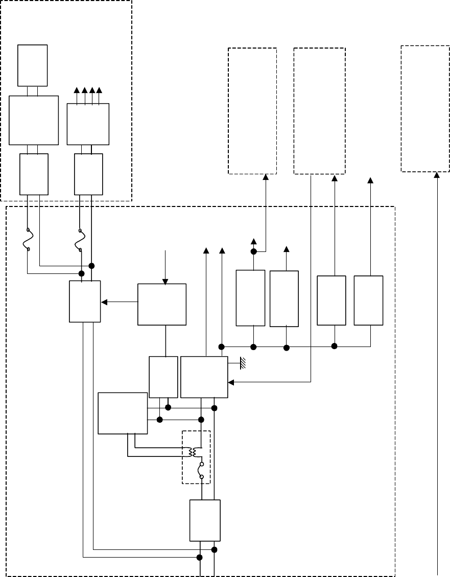
Figure 5 Primary Power Supply Diagram,
Type JMA-5208/HS, JMA-5212-4/6/4HS/6HS, JMA-5222-7/9
DC24V
+30%-10%
DC24V
+30%-10%
Processor NDC-1460
Filter
PWR
SENSE
P12V
±12V
AVR
PWR
CNT
Relay
+5V AVR
+3.3V
Poly-sw
Poly-sw
Filter
Filter
Motor
Motor
Control
AVR
System
Power
Supply
Scanner Unit NKE-2062/2103/2254
NSK UNIT
NCT-4106A
(option)
Power SW
Keyboard Unit
NCE-7699A
15 inch LCD
NWZ-164
To GPS(6W)
0.5A
0.5A
Logic
Logic
4A
2A
Analog
Analog
PWR-O
+12V 1.0A
-12V 0.2A
F3
F2
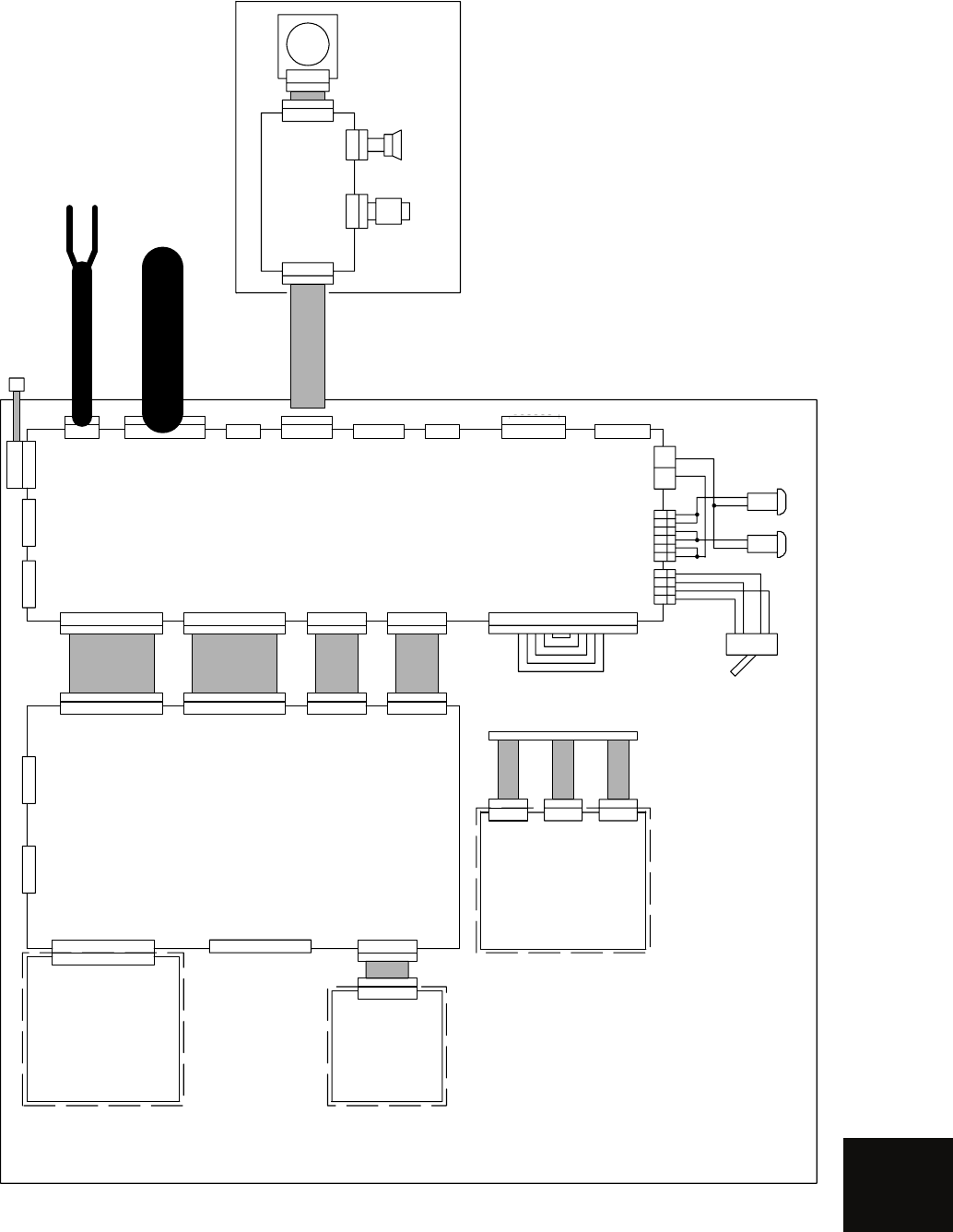
APPENDIX
Figure 6 Processor Unit, NDC-1460 Inter-connection Diagram
CDC-1186E
ATA UNIT(OPTION)
J1-64P
J303-64P
J4405-28P
J4901-6P
CDJ-2193A
PLOTTER
CONTROL UNIT
PC490(OPTION)
J4402-32P
W419 H-7ZCRD0934
CDC-1350 RADAR PROCESSOR CCT.
PC440
J4406-10P
DVI EXT RGB
CML-773 NDC-1460 INTERCONNECTION DIAGRAM OF PROCESSING UNIT
J302-64P
J4403-30PJ4401-10PJ4404-10P
J4407-6P
J510-6P
P4311-14P
J1-4P J400-6P
W402 H-7ZCRD1150
J5002-32P
J5003-30P
W403 H-7ZCRD1148
W404 H-7ZCRD1151
W418 H-7ZCRD1513
W401 H-7ZCRD1149
J5004-10PJ5005-10P
CMH-1353
AIS INTERFACE
(OPTION)
J4311-14P
W418 H-7ZCRD1473
W405 H-7ZCRD1168
J5001-4P J5001-6P K2
1234 12345 NOCOM
1
2
3
4
SPA-2-51-10A-DC50V F2(5/A10A) F3(10A)
W406 H-7ZCRD1521
J1-7PJ2-16PJ3-5PJ4-14PJ5-8PJ6-7PJ7-15PJ8-9P
CBD-1702A POWER SUPPLY & TERMINAL BOARD CCT. PC501
J5007-14P J5008-14P
NDC-1460 PROCESSING UNIT
POWER CABLE CFQ-5436-5(5m)
INTERUNIT CABLE CFQ-6912-5/10/15/20/30/40/50/65 (5m/10m/15m/20m/30m/40m/50m/65m)
SCANNTER
W601 H-7ZCRD1481
1A
2A
SHIP’S MAIN DC24V
J6001-14P
CCK979 PANEL CCT.
PC600
J6002-6P
J5012-8P W407 CFQ-5462
J9-14P
J6003-6P
NCE-7699A PANEL UNIT
J6004-2P TRD-101S(BK)N1
W602 H-7ZCRD1482
W603
H-7ZCRD1475
SPEAKER : MM283IN8-06
CQC-1024
PS/2TRACKBALL(OPTION)
W604 H-7ZCRD1474
CMD-1001 NCE-7699A INTERCONNECTION DIAGRAM OF PANEL UNIT
6
AIS UNIT and TT UNIT must be fitted on
ships compliant to IMO.
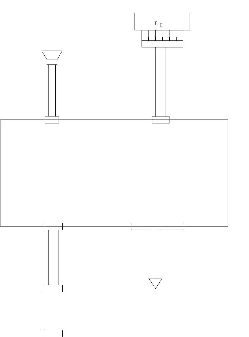
Figure 7 Key-board Unit, NCE-7699A Inter-connection Diagram
PS/2 TRACKBALL
(OPTION)
J6101
MD-S6000
PS/2
CQC-1204
P/J6103
S6B-PH-K-S
W603
H-7ZCRD1475
W601
H-7ZCRD1481
W604
H-7ZCRD1474
W602
H-7ZCRD1482
Processing Unit
NDC-1460
SPEAKER
MM283IN8-06
TRD-101S(BK)N1
P/J6003
B6B-PH P/J6004
S2B-PH
P/J6001
B14B-PH P/J6002
B6B-PH
Keyboard Circuit
CCK-979
PC600
SP601
1
2
A
B
1
2
3
4
5
B601
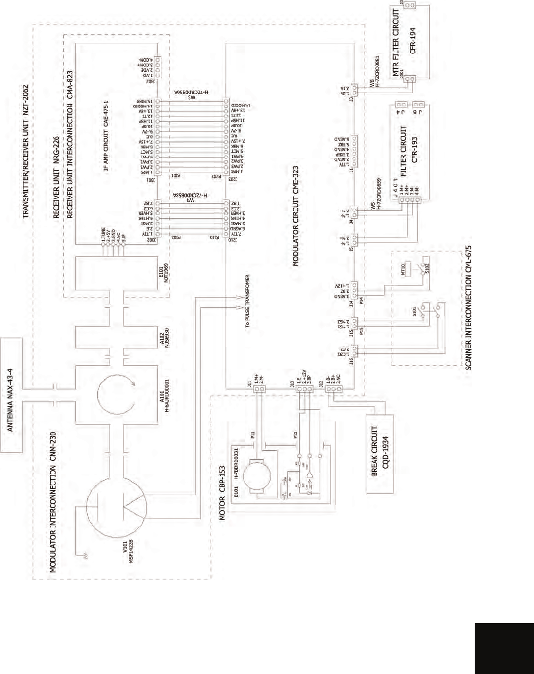
APPENDIX
Figure 8 NKE-2062 Scanner Unit Interconnection Diagram
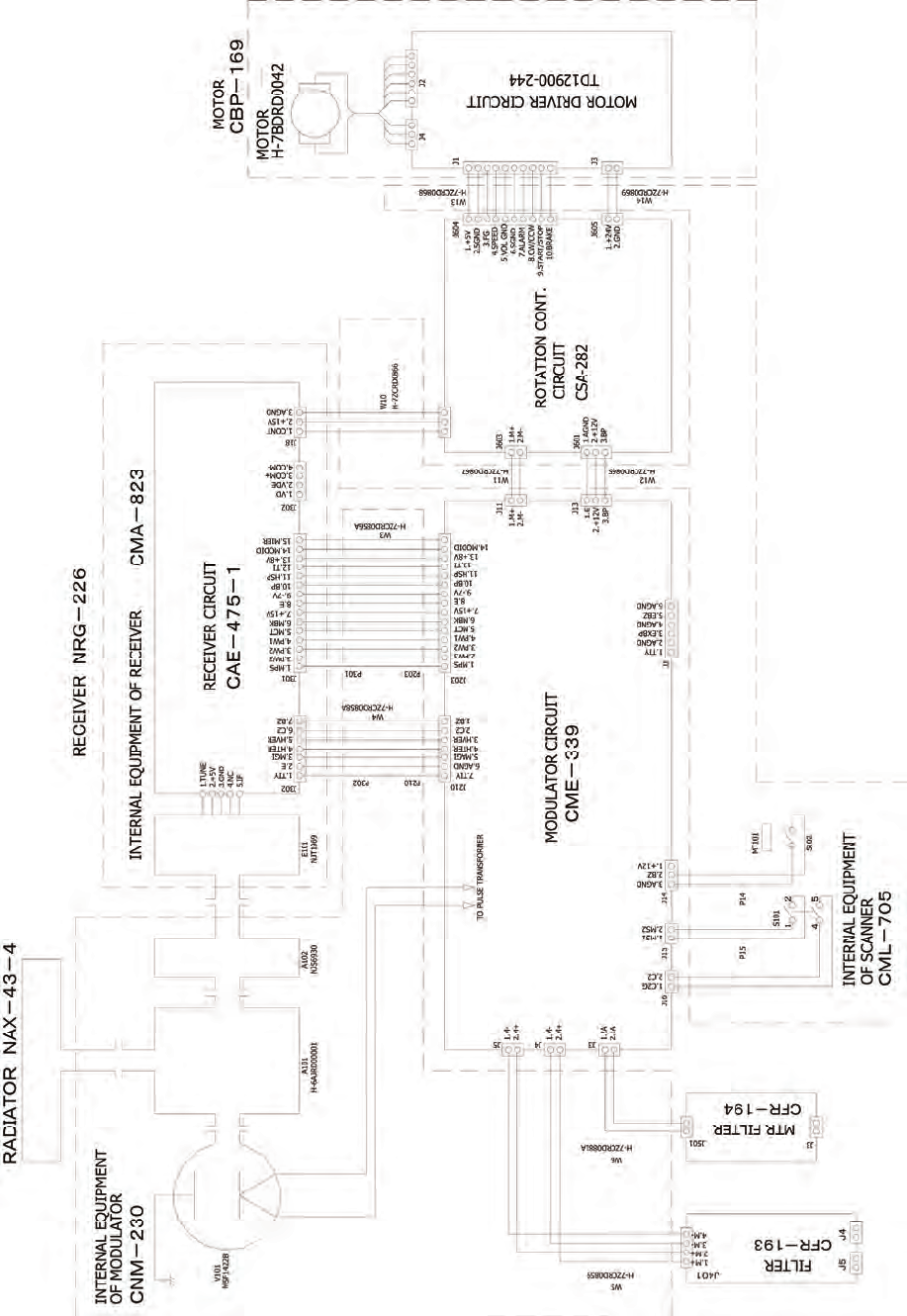
Figure 9 NKE-2062HS Scanner Unit Interconnection Diagram
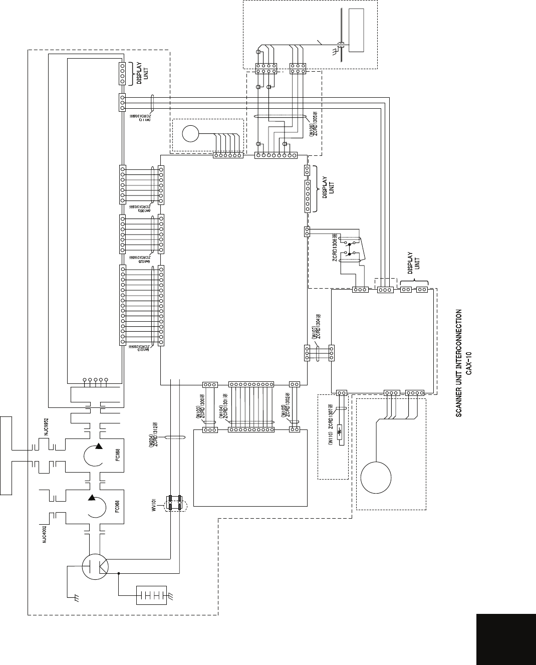
APPENDIX
付図19 Fig.19
NKE-2103
空中線機内接続図
Scanner Unit Interconnection Diagram
E101
NJT1969
A301
NJS6930
ANTENNA NAX-16B-4/6
FILTER
DUMMY
A101
1.TUNE
2.+5V
3.GND
4.NC
5.IF
IF AMP CIRCUIT (PC301)
CAE-529-1
MAG
MAGNETRON
V101
MAF1565N
POWER SUPPLY
CIRCUIT
(PC1001)
CBD-1783
1.2A
2.1A
J1001
J201
15.NC
4.PW1
5.MCT
6.MBK
7.+15V
8.AGND
9.-7V
10.BP
11.HSP
1.MPS
2.PW3
3.PW2
12.TI
13.+8V
14.MOD ID
T201-16
T201-15
1.MH
3.MN
J1003
J202
4.HTER
1.TIY
2.AGND
3.MAG.I
5.HVER
6.C2
7.BZ
J203
4.PMS
1.PTI
2.PTE
3.LVR
5.GND
6.TXI
7.TXE
1.2A
2.1A
J3
6.AGND
J1
4.AGND
1.ETIY
2.AGND
3.EXBP
5.EXBZ
SAFETY SWITCH
WS101
MODULATOR CIRCUIT
(PC201)
CME-363
J301
15.NC
4.PW1
5.MCT
6.MBK
7.+15V
8.AGND
9.-7V
10.BP
11.HSP
1.MPS
2.PW3
3.PW2
12.TI
13.+8V
14.MOD ID
J302
4.HTER
1.TIY
2.AGND
3.MAG.I
5.HVER
6.C2
7.BZ
J303
4.PMS
1.PTI
2.PTE
3.LVR
5.GND
6.TXI
7.TXE
4.COM-
1.VD
2.VDE
3.COM+
J2
J18
1.HMCNT
2.+15V
3.GND
SE
B102
J8
4.PMS
1.PTI
2.PTE
3.LVR
5.E
6.TXI
7.TXE
4.ΦB
1.ΦZ
2.E
3.ΦA
5.+12V
6.F.G.
YEL
BLK
BLU
WHT
RED
SHIELD
P8 1.PTI
2.PTE
1.LVR
2.PMS
3.E
3.TXI
4.TXE
J81
J82
P81
P82
WHT
BLK
BLU
RED
BLK
WHT
BRN
PM
NJU-85
7ZCRD1280※
1.2A
2.1A
J1503
1.MPS
2.MCT
J1501
3.MBK
1.HMCNT
2.+15V
J1505
3.AGND
1.2A
2.1A
J4
1.2A
2.1A
J5
1.MPS
2.MCT
J209
3.MBK
1.C2G
2.C2
J210
1.2A
2.1A
J204
J206
1.MH
3.MN
MOTOR CONTROL POWER CIRCUIT
(PC1501)
CBD-1779
1.MCNT+
J125
3.NC
1.M+
2.NC
J1502
3.M-
4.NC
2.MCNT-
MOTOR
B101
H-7BDRD0048
MORTOR CBP-202
BREAK CIRCUIT CFA-252
YEL GRN
A103
RECEIVER UNIT NRG-610
MIC
S.G.
S.G.
(OPTION)
5
4
2
1
J208
D.L
1.MS1
2.NC
J1504
3.MS2
TRANSMITTER/RECEIVER UNIT NZT-2103 TRANSMITTER/RECEIVER UNIT
INTERCONNECTION
CMK-599
8.NC
J205
1.+15V
2.+12V
3.+8V
4.AGND
5.-15V
6.X1
7.X2
8.+5V
9.HTER
10.HVER
J1002
1.+15V
2.+12V
3.+8V
4.AGND
5.-15V
6.X1
7.X2
8.+5V
9.HTER
10.HVER
A102
(RECEIVER UNIT INTERCONNECTION CMA-823)
ENCODER CHT-71A
S.G.
CFR-234
MAG FILTER
CIRCUIT
100pF×3
A104
TB1
1-2short : Nomal Speed
2-3short : High Speed
Figure 10 NKE-2103 Scanner Unit Interconnection Diagram
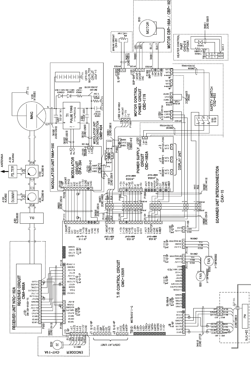
Figure 11 NKE-2254 Interconnection Diagram of Scanner Unit
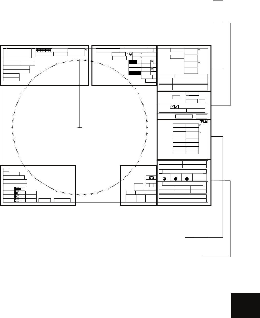
APPENDIX
Figure 12 JMA-5200MK2 ON-screen Controls
6+
-Rings 1NM
RM(R) H UP
Off Center
Transmit
GND
HDG
Compass Cursor (Off )C
True 089.6
5.37NM 35 33.037'
EBL1 T
VRM1
EBL2 T
VRM2
NM
NM
PC
CCRP1
N
140 01.597'E
MRK
TRK 30 sec
Map Shift
CPA
Ring
HL
Off
Data
Off
x2
IR Low
ENH Level1
PROC Off
FUNC Off
Gain
Sea
Rain
TUNE
MAN
Multi TGT Num
()
000.0
0.0kn
kn
CMPS
GPS
HDG
SPD
UTC 2007-12-07 05:10
GPS 35 33.000'N
139 55.000'E
R9minVector NM 1minLimit 0.1 R0.1PAST POSN NM
Range
Filter
R10minTrails
BRG
TGT ID
Range
Cource
Speed
NM
kn
BCR NM
BCT min
Brilliance
< >
Panel VID TT Day1
Menu
< >
RADARClose TT
MapPlot Test
No Alarm
000 010
020
030
040
050
060
070
080
090
100
110
120
130
140
150
160
170
180
190
200
210
220
230
240
250
260
270
280
290
300
310
320
330
340
350
000.0
X-BAND
Master
MP
MAN
Auto
1 32
MOB
045.0
3.00
135.0
6.00 C
CPA NM
TCPA min
09:52
Association
AIS
WGS84
000.0
0.0
COG
SOG
Area 1
(Top-left corner of
the radar dis
p
la
y)
Area 3
(Top-right corner of
the radar dis
p
la
y)
Area 2
(Bottom-left corner of
the radar dis
p
la
y)
Area 4
(Bottom-right corner of
the radar dis
p
la
y)
Area 5
(Own ship’s information)
Area 6
(Other ship’s information)
Area 7
(Panel display)
Area 8
(Operation/message)
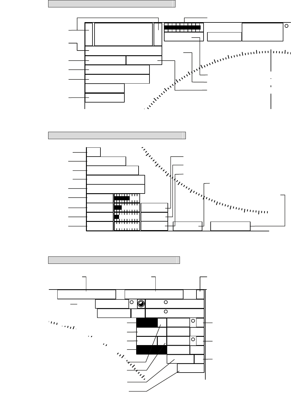
Area 1 (Top-left corner of the radar display)
Area 2 (Bottom-left corner of the radar display)
Area 3 (Top-right corner of the radar display)
6+
-Rings 1NM
RM(R) H UP
Off Center
Transmit
GND
HDG
Compass 000
310
320
330
340
350
000.0
X-BAND
Master
MP
Refer to Section 3.4.3.
Refer to Section 3.4.9,
3.4.10 or 4.2.
Refer to Section 3.5.8.
Refer to Section 3.5.9.
Refer to Section 3.4.1
or 3.4.2.
Refer to Section 2.3.1.
Refer to Section 3.5.11.
Refer to Section 5.1.2.
Refer to Section 3.5.7.
Refer to Section 7.1.2.
x
2
IR Low
ENH Level1
PROC Off
FUNC Off
Gain
Sea
Rain
TUNE
MAN
Multi TGT Num
()
1
190
200
210
220
230
MAN
Auto
Refer to Section 3.5.14.
Refer to Section 3.4.8.
Refer to Section 3.5.12.
Refer to Section 3.5.13.
Refer to Section 3.10.
Refer to Section 3.4.5.
Refer to Section 3.4.6.
Refer to Section 3.4.7.
Refer to Section 3.4.4.
Refer to Section 3.4.6.
Refer to Section 3.4.7.
Refer to Section 3.4.4.
Refer to Section 3.5.18.
Refer to Section 3.5.18.
Cursor (Off )C
True 089.6
5.37NM 35 33.037'
EBL1 T
VRM1
EBL2 T
VRM2
NM
NM
PC
CCRP1
N
140 01.597'E
10
020
030
040
050
045.0
3.00
135.0
6.00 C
Refer to Section 4.1.
Refer to Section 3.5.2.
Refer to Section 3.5.4.
Refer to Section 3.5.2.
Refer to Section 3.5.4.
Refer to Section 3.5.3.
Refer to Section 3.5.3.
Refer to Section
5.1.4.
Refer to Section
3.5.16 or 5.1.4. Refer to Section 2.3.3
Refer to Section 3.5.3.
Refer to Section 3.5.3.
Refer to Section 3.5.4.
Refer to Section 3.5.5
or 3.5.6.
Refer to Section 3.1.4.
,
7.1.6.
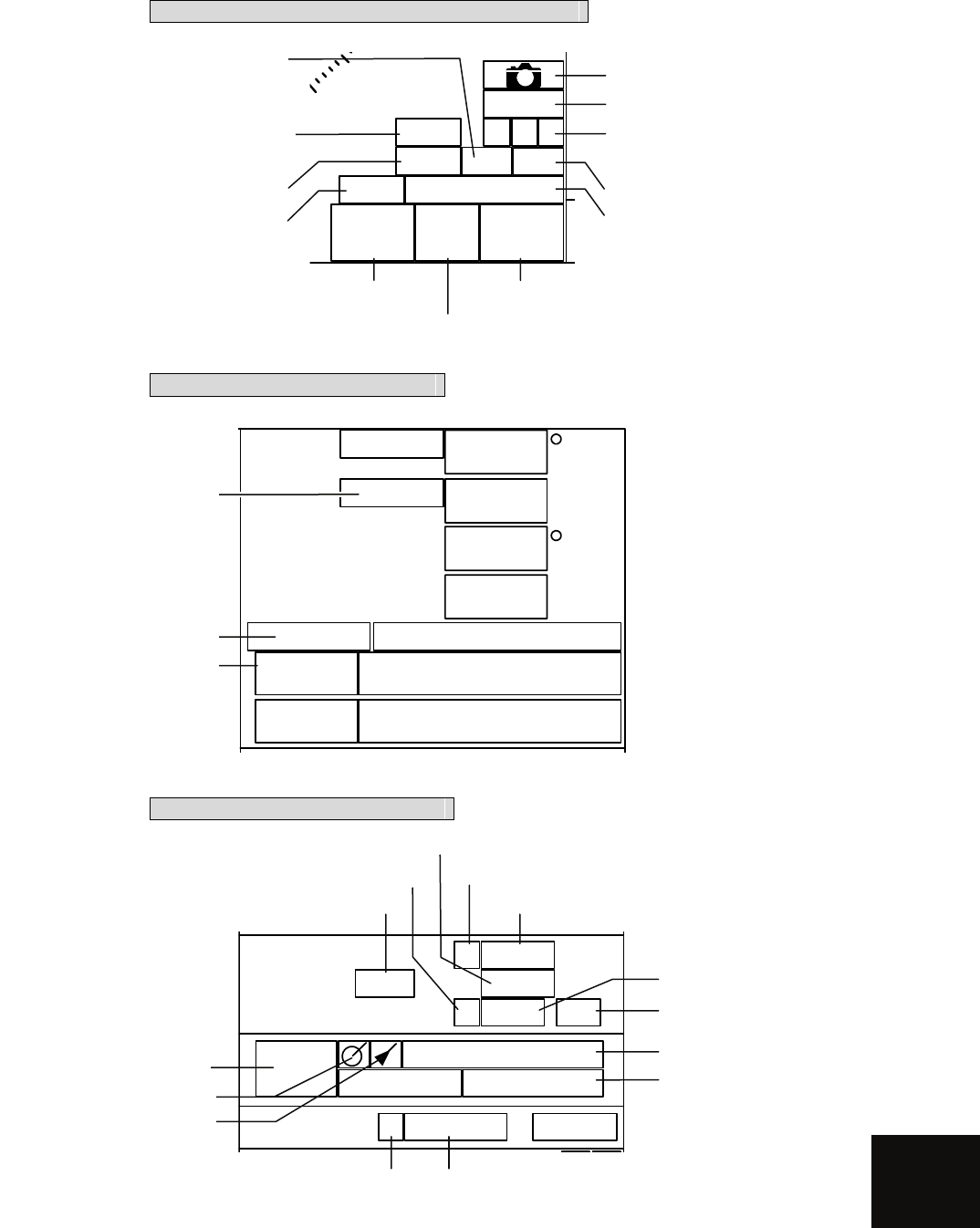
APPENDIX
Area 4 (Bottom-right corner of the radar display)
Area 5 (Own ship’s information)
Area 6 (Other ship's information)
000.0
0.0kn
kn
CMPS
GPS
HDG
SPD
UTC 2007-12-07 05:10
GPS 35 33.000'N
139 55.000'E
WGS84
000.0
0.0
COG
SOG
Refer to Section 7.2.5.
Refer to Section 7.3.6.
R9minVector NM 1minLimit 0.1 R0.1PAST POSN NM
Range
Filter
R10minTrails 09:52
Association
AIS
Refer to Section 5.3.3.
Refer to Section 5.1.2.
Refer to Section 5.1.2.
Refer to Section
3.5.10 or 3.9.2. Refer to Section
3.5.10 or 3.9.2.
Refer to Section 5.6.1.
Refer to Section 5.6.1.
Refer to Section 5.4.1.
Refer to Section 5.3.8.
Refer to Section 5.1.5.
Refer to Section 5.6.1.
Refer to Section 5.1.5.
Refer to Section 5.1.3.
Refer to Section 5.1.7.
MRK
TRK 30 sec
Map Shift
CPA
Ring
HL
Off
Data
Off
140 1 32
MOB
Refer to Section 3.6.1.
Refer to Plotter Option
Manual Section 3.42.
Refer to Section 3.7.1,
3.7.2 or 3.7.3.
Refer to Section 2.3.4.
Refer to Section 3.5.15.
Refer to Section 3.6.2.
Refer to Section 3.9.6.
Refer to Section 3.6.2
or 3.6.3.
Refer to Section 3.4.11. Refer to Section 5.1.6.
Refer to Section 3.4.10.
Refer to Plotter Option
Manual Section 3.35.
Refer to Section 2.3.5.
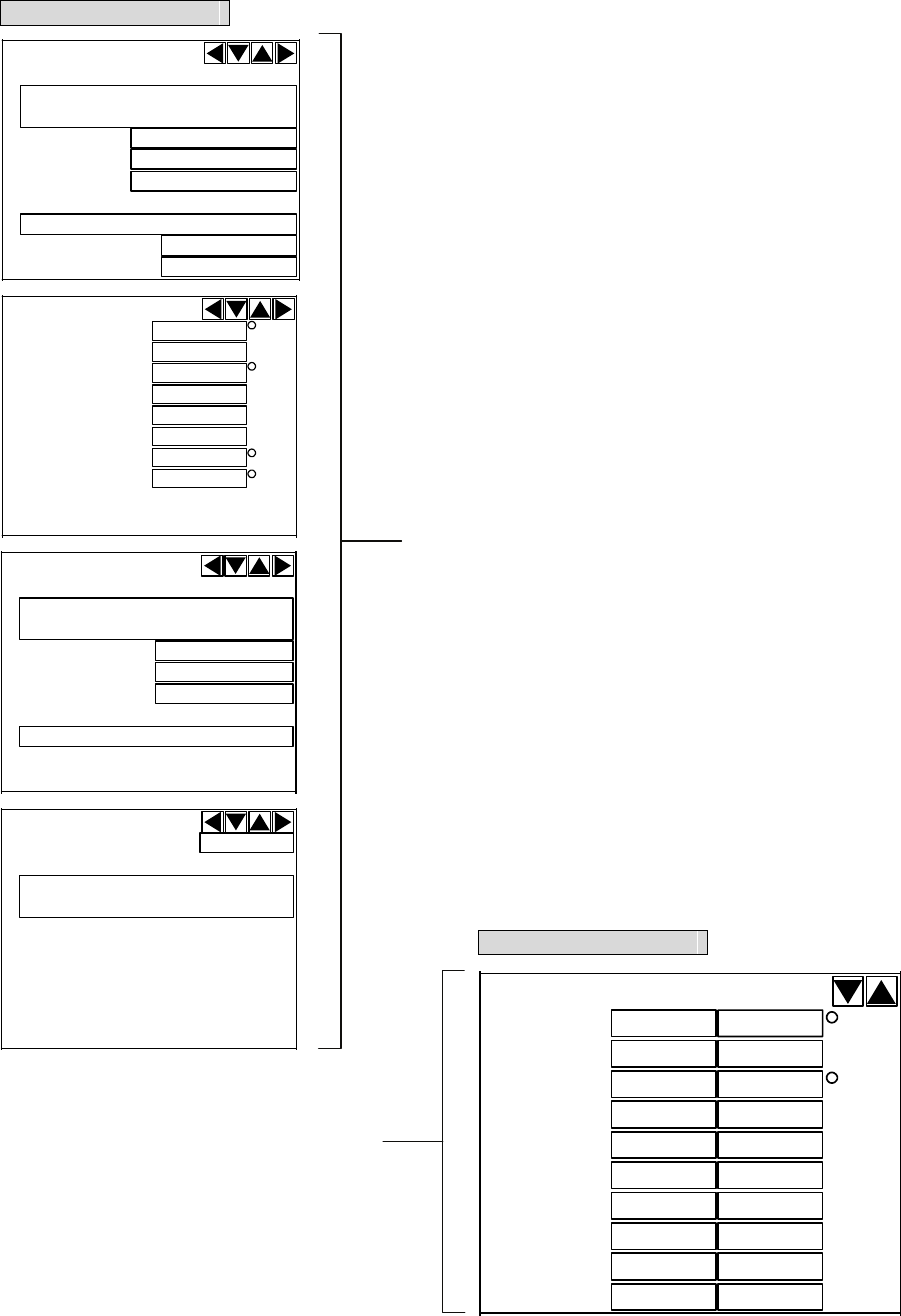
DEST
AIS ID
ETA
EPFS
RAIM
POSN
POSN Accuracy
BRG
AIS ID
Range
SOG
CPA
COG
TCPA
NM
kn
min
NM
/min
HDG
ROT
Name
AIS ID
Call SIGN
IMO Number
MMSI
NAV Status
AtoN Real/Virtual
AIS ID
AtoN Type
Area 7 (Panel display)
BRG
TT ID
Range
Cource
Speed
NM
kn
BCR NM
BCT min
CPA NM
TCPA min
BCR NM
BCT min
Area 7 (Panel display)
Refer to Section 5.3.6.
Refer to Section 5.2.3.
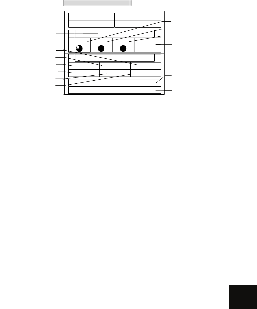
APPENDIX
Area 8 (Operation/message)
Refer to Section 2.3.9.
Refer to Section 3.2.2.
Refer to Section ?.?.?.
Refer to Section ?.?.?.
Refer to Section 3.11.1.
Refer to Section 3.9.6.
Refer to Section 8.3.1. Refer to Section 5.5.
Refer to Section 3.3.3.
Refer to Section 3.3.2.
Refer to Section 3.3.2.
Refer to Section 3.3.4.
Refer to Section 3.3.7
or 5.5.
Brilliance
< >
Panel VID TT Day1
Menu
< >
RADARClose TT
MapPlot Test
No Alarm
With Plotter
With TT Unit
With AIS Unit
With TT or AIS Unit
With TT and AIS Unit
Main Menu
-1 RADAR Menu
3Marker Setting -1EBL1 Setting -1
EBL1 Bearing REF
2 EBL1 Floating
3 EBL1 Bearing Fix
2EBL2 Setting -1
EBL2 Bearing REF
2 EBL2 Floating
3 EBL2 Bearing Fix
3 VRM1 Range Unit
4 VRM2 Range Unit
5Parallel Line - 1 Operation Mode
2Parallel Cursor 1 Range Scale Link
2 Referece Bearing
3 Floating
4 Bearing Mode
5 DISP For Individual Line - 1 Line 1
2 Line 2
3 Line 3
4 Line 4
5 Line 5
6 Line 6
7 Line 7
6 Bearing
7 Interval
3Parallel Index Line 1 Range Scale Link
2 Referece Bearing
3 Floating
4 Bearing Mode
5 DISP For Individual Line - 1 Line 1
2 Line 2
3 Line 3
4 Line 4
6 Bearing
7 Distance
6 Cursor Setting - 1 EBL/VRM Control CURS
2 Cursor Length
3 Cursor Pattern
4 Distance Unit
7 EBL Maneuver Setting - 1 EBL Maneuver
2 Reach
3 Turn Mode
4 Tuen Set
8Rectangle Cursor - 1 Rectangle Cursor Display
2 Make Rectangle Cursor
3 ENT
4 Unit Of Distance
4 Screen Setting - 1 Display Color Setting - 1 Day/Night
2 Own Ship
3 Outer PPI
4 Inner PPI
5 Character
6 RADAR Echo
7 RADAR Trails(Time)
8 RADAR Trails(All)
9 TT/AIS
2 Brilliance Setting - 1 RADAR Video
2 RADAR Trails
3 TT/AIS
4 Range Riings
5 EBL/VRM
6 Character
7 Panel
8 Own Ship
3 Graph Panel Setting - 1 Panel1(Target)
2 Panel2(Marker)
3 Panel3(Waypoint)
4 Panel4(Cursor/EBL/VRM)
5 Panel5(Graph)
4 Depth Graph Setting 2 Depth Range
3 Time Range
4 Depth Unit
5 Wind Graph 2 Wind Speed Unit
6 DIR/DIST EXP Display
7 TEMP Graph Setting 2 Display Graph Color
3 Water TEMP Range - 1 Temperature setting(MIN)
2 Temperature setting
3 Temperature setting
4 Temperature setting
5 Temperature setting
6 Temperature setting(MAX)
4 Time Range
8 Course Bar Setting 2 Autopilot Course
3 ROT Scale
9 Next
↓
1 Screen Capture Setting - 1 Select Capture Item - 1 Radar Echo
2 Trails
3 Chart
4 Graphic
2 File Erase
3 AUTO Capture Interval
4 AUTO File Erase
JMA-5200MK2 Series Radar Menu Function List

5 TXRX Setting - 1 PRF Fine Tuning
2 Stagger Trigger
4 PRF
5 Band Select
6Inter Switch Setting - 1 Select TXRX
7 Pulse Length Pattern - 1 3NM 10kw
2 6nm
3 12NM
- 1 3NM 25kw
2 6NM
3 12NM
- 1 3NM 6kw
6 NAV Information - 1 Waypoint Display
2 NAV Display Setting - 1 Line1
2 Line2
3 Line3
4 Mark1
5 Mark2
6 Mark3
7 Mark4
-3 User Map Setting - 1 Own Ship Position
2 Load - 1 Device
2 Load User Map
3 Unload
4 Save - 1 Device
2 Save User Map
3 All Files to Card2
5 Erase - 1 Device
2 Erase User Map
6 Edit User Map - 1 Clear Map Obuject - 1 Line1
2 Line2
3 Line3
4 Mark1
5 Mark2
6 Mark3
7 Mark4
8 All
2 Make Map Object - 1 Line1
2 Line2
3 Line3
4 Mark1
5 Mark2
6 Mark3
7 Mark4
8 Enter
3 Correct
4 Delete
5 Insert
7 Shift
8 Shift Clear
4Geodetic
7 NAV Equipment Setting - 1 Set GYRO
2 Heading Equipment
3 Speed Equipment
4 Manual Speed
5 MAG Compass Setting - 1 Heading Correction
2 Correct Value
6 Set/Drift Setting - 1 Correction
2 Set
3 Drift
7 GPS Setting -1
GPS Process Setting - 1 Position
2 Exclusion
3 Geodetic
4 Antenna Height
5 Fix Mode
6 DOP Level
7 Position Average
8 Master Reset
9 Send Data
2DGPS Setting - 1 Mode
2 Frequency
3 Baud Rate(BPS)
4 DGPS Mode
5 Send Data
3SBAS Setting - 1 Mode
2 Ranging
3 NG SBAS
4 SBAS Select Mode
5 SBAS No.
6 Send Data
4 GPS Status
8Weather INFO Setting - 1 Display Weather INFO
2 SEL Observation Place
3 RX Message Display
4 RX Buzzer
8 Graphic Display
9Plot Menu
0 EXIT

RADAR Menu - 1IR
2 Process
3 Target Enhance
4 Zoom
5 SART
6Process Setting - 1 Video Latitude
2 Video Noise Rejection
3 AUTO Dynamic Range
4 Process Switch
5 2nd Process Mode
6 Process Switch Rrange
7 Fast Target Detection
8User Function Setting - 1 Function1 Setting -1 Mode
2IR
3 Process
4 Target Enhance
5 AUTO STC/FTC
7 Save Present State
8
9 Next
↓
1 Pulse Length 0.5nm
2 Pulse Length 0.75nm
3 Pulse Length 1.5nm
4 Pulse Length 3nm
5 Pulse Length 6nm
6 Pulse Length 12nm
8 Pulse Length Pattern - 1 3NM
2 6nm
3 12NM
9 Next
↓
1 Video Latitude
2 Video Noise Rejection
3 AUTO Dynamic Range
4 PROCESS SWITCHING
5 2nd Process Mode
6 Process Switch Range
7 Fast Target Detection
9 Next
↓
1 Trails Interval
2 Trails Mode
3 Trails Ref Level
4 Trails Reduction
5 Time/All Combine
6 Trails Process
7 MAX Interval
9 Next
↓
1 Gain Offset
2 PRF
3 Small Buoy Detection
4 Fishnet Detection
5 Antenna Height
8 Set Mode Default
9 Initialize
2 Function2 Setting
3 Function3 Setting
4 Function4 Setting
7RADAR Trails Setting - 1 Trails Interval
2 Trails Mode
3 Trails REF Level
4 Trails Reduction
5 Time/All Combine
6 Trails Process
7 MAX Interval
8
9 Next
↓
1 File Load
2 File Save
3 File Erase
4 Trails Erase - 1 Trails Erase Mode
2 Trails Erase Start
3 Eraser Size

8 RADAR Sub Menu -1PIN Setting - 1 Load PIN Setting
2 Save PIN Setting
3 Delete PIN Setting
2Multi Dial Setting 1 Vector Length
2 Trails Length
3 TT TGT Display No.
4 C-UP Angle
5 Own Track Color
6 Mark/Line Color
3User Key Setting - 1 User Key1
2 User Key2
4 Date/Time Setting - 1 UTC/LOCAL
2 Local Date
3 Local Time
4 Time Zone
5 Display Style
5 Buzzer Volume
6 Jog Dial Button Mode - 1 Left Jog Dial
2 Right Jog Dial
9Test Menu -1 Self Test - 1 Memory Test - 1 SDRAM
2 SRAM
3 FLASH ROM
4 GRPHIC
2 TXRX Test - 1 SAFETY SWITCH
2 AZI PULSE
3 HL PULSE
4 MH CURRENT
5 TRIGGER
6 VIDEO
3 Line Test - TXRX
NSK
COMPASS
COM1
COM2
COM3
COM4
Plotter Key
2 Monitor Test - 1 Pattern 1
2 Pattern 2
3 Pattern 3
4 Pattern 4
5 Pattern 5
6 Pattern 6
7 Pattern 7
3 Keyboard Test - 1 Key Test
2 Buzzer Test
3 Light
4 MON Display
5 Alarm List/Log
6 System Info
0EXIT
Plot Menu -1Own Track Setting - 1 OWN Track Interval
2 DISP Own Track
2 DISP Own Track Color - 1 All
2 White
3 Cyan
4 Blue
5 Green
6 Yellow
7 Pink
8 Red
3 Clear Own Track
3 Clear Own Track Color
4 OWN Track Memory
5Track Color
6 Track Memory
7 Num/Vector Display
9 Next
↓
1 Water Depth Setting - 1 Depth setting(MIN)
2 Depth setting
3 Depth setting
4 Depth setting
5 Depth setting
6 Depth setting(MAX)
2 Water TEMP. Setting - 1 Temperature setting
2 Temperature setting
3 Temperature setting
4 Temperature setting
5 Temperature setting
6 Temperature setting
3 Tideway Setting - 1 Tideway Size
2 Layer A
3 Layer B
4 Layer C

2Mark Setting - 1 Display Mark Type - 1 All
2 Fish 1
3 Fish 2
4 Fish heaven (round)
5 Fish heaven (square)
6 Wreck
7 Squid
8 Scallop
9 Next
↓
1 Crab
2 Lobster
3 Mola
4+
5X
6Y
7 Hour glass
8 Star
9 Next
↓
1 Buoy 1
2 Buoy 2
3 Buoy 3
4 Number
5…
6-
7._
8・
2 Display Mark Color - 1 All
2 White
3 Cyan
4 Blue
5 Green
6 Yellow
7 Pink
8 Red
3 Clear Mark Color/Type
4 Mark/Line Entry
5 Mark/Line List
6 New Mark/Line Input - 1 Type
2 Color
3 LAT/LON
4 Comment
9 New Mark Input ⇔9 New Line Input
3 WPT/Route Settig - 1 Waypoint Alarm
2 Route Alarm
3 Set Route Sequence
4 Select Route
5 Waypoint Entry
6 Waypoint Input
7 Save TEMP. Route
8 Route Alarm Color
4 WPT/Route Operation - 1 Route Sequence
2 Waypoint Switch Mode
3 Waypoint Skip
4 Waypoint Back Skip
5 Set/Cancel Waypoint

5Map Setting - 1 Fill Land Area
2 C-MAP Setting - 1 Grid Display
2 Sounding Display
3 Sounding Unit
4 Light Sectors Display
5 Light Sectors Level
6 Chart Boundary
7 Buoy&Beacon
8 Names
9 Next
↓
1 Land Marks
2 River&Lake
3 Cultual
4 Bottom Type
5 Under Water
6
7 Depth Contour
3 JRC/ERC Setting - 1 Day/Night
2 Color of Land
3 Bright of Land
4 Color of Sea
5 Bright of Sea
6 Color of Name
7 Bright of Name
8 Bright of Track/Mark/Line
9 Next
↓
1 LAT/LON Line
2 Color of L/L Line
3 Bright of L/L Line
4 ERC Display Request
5 ERC Mark
6 JRC Card Display - 1 Lighthouse
2 Buoy
3 Rough Line
4 Other Line
7 Copy JRC Chart to CF
8 Fishing Area Display
4 Contour Setting - 1 10m
2 20m
3 30m
4 40m
5 50m
6 60m
7 70m
8 80m
9 Other
5 Map Display Setting - 1 Shift Coast Line 1
2 Shift Coast Line 2
3 LAT/LON Correction
4 Map Center Position
5 LORAN C Correction - 1 Chain
2 TD1
3 TD2
4 TD1 Correction
5 TD2 Correction
6 LORAN A Correction - 1 LOP1
2 LOP2
3 TD1 Correction
4 TD2 Correction
7 DECCA Correction - 1 Chain
2 LOP1
3 LOP2
4 LOP1 Correction
5 LOP2 Correction
6 Select JRC Chart File - 1 Disp File Information
・・・・
* Disp File Information
7 Map Draw AZI Mode
8 JRC Chart Draw Mode
6 MEM CAPA/Copy - 1 Copy Internal -> Card2
2 Copy Card2 -> Internal
3 Copy Card1->Card2
4 Clear File
5 Card2 Own Track Display
6 Card2 Mark Display
7 Show Card1
8 Show Card2
7 CLR MEM/INIT Card - 1 Clear Mark/Line Data
2 Cleat WPT/Route Data
3 Format Card2
8Plot Setting - 1 Scalse/Couse Up Setup - 1 Scale
2 Preset Scale
3 Course Up Data -1 Tolerance
2 Averaging
3 Round Speed
2 Curosr/Number Display - 1 Shape of Current Position
2 Current POS Blink
3Unit of Speed
4 Unit of Distance
5 Current Position Display
6 Select Line
7 Select Mark Size
8 Select Cursor Mark
9 Next
↓
1 Event Mark 1
2 Event Mark 2
3 Select WPT Mark Size
4 Cursor Vector DISP
5 Cursor Vector Length
6 Waypoint Vector
7 Status of Origin/DEST
9 Next
↓
1 WPT Number Display
2 RTE Number Display
3 Scalebar Display
4 Numeric Mark
5 Comment Font Size
3 Basic - 1 AUTO Backup
0 EXIT
TT Menu - 1 TT Setting 1
2 TT Symbol Didplay
3 Target Number Display
4
5
6
2 AIS Setting - 1 AIS Function
2 AIS Symbol Display
3 AIS Received Message 1 Addressed Message
2 Broadcast Message
4 Display Lost Target Data
5 Own Ship's AIS Data
6 AIS Filter Setting - 1 Filter Type
2 Make AIS Filter
3 Filter Display
4 ENT
5 Filter Mode
7 Target Number Display
8 AIS Alarm Setting 1 CPA/TCPA Alarm
2Lost Alarm
3
4
5
9 Next
↓
2 AIS Data DISP Setting
3 Target Setting - 1 Association Setting 1 Association
2 Priority
3 Bearing
4 Range
5 Course
6 Speed
7 Hysteresis
8 Non-hysteresis
9 Applicable AIS Target
2 Vector Time
3 Past Position
5 CPA Limit
6 TCPA Limit
7CPA Ring
4 Target Track Setting - 1 Track Function
2 Track Color - 1 All
2 Target Track No.1
3 Target Track No.2
4 Target Track No.3
5 Target Track No.4
6 Target Track No.5
7 Target Track No.6
8 Target Track No.7
9 Next
↓
1 Target Track No.8
2 Target Track No.9
3 Target Track No.10
4 Target Track No.11
5 Target Track No.12
6 Target Track No.13
7 Target Track No.14
8 Target Track No.15
9 Next
↓
1 Target Track No.16
2 Target Track No.17
3 Target Track No.18
4 Target Track No.19
5 Target Track No.20
3 Track Display - 1 All
2 Target Track No.1
3 Target Track No.2
4 Target Track No.3
5 Target Track No.4
6 Target Track No.5
7 Target Track No.6
8 Target Track No.7
9 Next
↓
1 Target Track No.8
2 Target Track No.9
3 Target Track No.10
4 Target Track No.11
5 Target Track No.12
6 Target Track No.13
7 Target Track No.14
8 Target Track No.15
9 Next
↓
1 Target Track No.16
2 Target Track No.17
3 Target Track No.18
4 Target Track No.19
5 Target Track No.20
4 Track Memory Interval
5 Clear Track Color
6 Clear Track Number
7 Card2 Track Display
5AZ Setting - 1 AZ - 1 AZ 1
2 AZ 2
3 Make AZ 1
4 Make AZ 2
5 ENT
2 RADAR Alarm - 1 Sector RADAR Alarm - 1 Sector Alarm 1
2 Sector Alarm 2
3 Make Sector Alarm - 1 Sector Alarm 1
2 Sector Alarm 2
3 ENT
5 RADAR Alarm Mode
6 Sensitivity Level
3 Set AZ Key - 1 AZ Alarm - 1 AZ Alarm 1
2 AZ Alarm 2
2 Sector RADAR Alarm - 1 Sector Alarm 1
2 Sector Alarm 2
6 TT Test Menu - 1 Test Video
2 TT Simulator
3 Status
4 Gate Display

TT Individual Setting - 1 Name
2 Track Color
3 Association Priority
4 Reference Target
Adjust Menu -1 Equipment Setup - 1 Bearing Adjustment
2 Range Adjustment
3 Tune Adjustment
8 INSTALLATION - 1 DATE
2 NAME
3 COMPANY
9 Language
2 Maintenance Menu - 1 Safty Switch
2 Partial Master Reset
3 All Master Reset
4 Internal To Card2
5 Card2 To Internal
6 TXRX TIME CLR 1 TOTAL TIME CLR
2 TX TIME CLR
3 MOTOR TIME CLR
4 TXRX to Display Unit
5 Display Unit to TXRX
7 String Data Update
3AIS - 1 AIS Processor
2 Max Target
3 Receive AIS Messages - 1 Message 1
2 Message 2
3 Message 3
4 Message 4
5 Message 5
6 Message 6
7 Message 7
8 Message 8
9 Next
↓
1 Message 9
2 Message 10
3 Message 11
4 Message 12
5 Message 13
6 Message 14
7 Message 15
8 Message 16
9 Next
↓
1 Message 17
2 Message 18
3 Message 19
4 Message 20
5 Message 21
6 Message 22
7 Message 23
8 Message 24
9 Next
↓
1 Message 25
2 Message 26
3 Message 27
4 Message 28
5 Message 29
6 Message 30
7 Message 31
4 TXRX Setting - 1 Antenna Height
2 Tune Peak Adjustment
3 Tune Indicator
4MON - 1 MON INSTALL
2 MON Adjustment
3 MON Indicator
5 Manual Tune Adjustment
6 Sector Blank - 1 Sector1
2 Sector2
3 Sector3
4 Make Sector1
5 Make Sector2
6 Make Sector3
7 Output Pulse
8INTER SWITCH - 1 ISW INSTALL
3 S-ISW TXRX Power
9 TNI Blank - 1 TNI Blank
2 Make Sector

5 COM Port Setting - 1 Baud Rate -1 COM1(GPS)
2 COM2(PC)
3 COM3(NAV1)
4 COM4(NAV2)
5 COM5(COMPASS)
2 RX Sentence -1 GPS(LL/COG/SOG) - 1 GGA
2 RMC
3 RMA
4 GNS
5 GLL
6 VTG
2 GPS(WPT) - 1 RMB
2BWC
3BWR
3 Depth - 1 DPT
2 DBK
3 DBT
4 DBS
4 Wind - 1 MWV
2 MWD
5 Current - 1 Data Set Number
2 Layer A
3 Layer B
4 Layer C
3 TX Port -1 TTM(TT Target)
2 TLL(TT Target)
3 TTD(TT Target)
4 TLB(TT Target)
5 TTM(AIS Target)
6 TLL(AIS Target)
7 TTD(AIS Target)
8 TLB(AIS Target)
9 Next
↓
3 OSD
4 RSD
5 ALR
6 ACK
9 Next
↓
1 Remote Maintenance
2 NMEA0183 Output Format
3 NMEA0183 Talker
4 NMEA0183 TX Interval
5 APB
6 BOD
7 GGA
8 GLL
9 Next
↓
1 RMC
2 RMB
3 VTG
4 XTE
5 BWC
6 HDT
7 THS
4 RX Port -1 GPS
2 DLOG
3 Depth
4 Temperature
5 Wind
6 Current
7 Rate of Turn
8 Rudder
7 LINE MONITOR - 1 COM1(GPS)
2 COM2(PC)
3 COM3(NAV1)
4 COM4(NAV2)
5 COM5(NSK)
6 COM6(TXRX)
7 COM7(Keyboad1)
8 COM8(Keyboad2)
6 NAV Equipment Setting - 1 Set GYRO
2 Heading Equipment
3 Speed Equipment
4 Manual Speed
5 MAG Compass Setting - 1 Heading Correction
2 Correct Value
6 Set/Drift Setting - 1 Correction
2 Set
3 Drift
7 GPS Setting -1
GPS Process Setting - 1 Position
2 Exclusion
3 Geodetic
4 Antenna Height
5 Fix Mode
6 DOP Level
7 Position Average
8 Master Reset
9 Send Data
2DGPS Setting - 1 Mode
2 Frequency
3 Baud Rate(BPS)
4 DGPS Mode
5 Send Data
3SBAS Setting - 1 Mode
2 Ranging
3 NG SBAS
4 SBAS Select Mode
5 SBAS No.
6 Send Data
4 GPS Status
8Weather INFO Setting - 1 Display Weather INFO
2 SEL Observation Place
3 RX Message Display
4 RX Buzzer

7 Hull Display Setting 1 CCRP Setting
2 Ship's Outline
3 Beam line
8 RADAR/TT INIT SETUP - 1 Noise Level - 1 Main
2 Setting Mode
2 TT - 1 Vector Constant
2 Video TD Level
3 Video High Level
4 Video Low Level
5 Gate Size
6 Limit Ring
3 MBS - 1 MBS Level
2 MBS Area
9 Next
↓
1 Alarm outputs Setting 1 Critical Alarm - 1 Audio
2 Indications
3 Acknowledge State
2 Normal Alarm - 1 Audio
2 Indications
3 Acknowledge State
3 Relay Contact Mode
2Plotter -1
2 Priority To Draw C-MAP


MARINE RADARMARINE RADAR
EQUIPMENTEQUIPMENT
INSTRUCTIONINSTRUCTION
MANUALMANUAL
JMA-5208/HSJMA-5208/HS
JMA-5212-4/6JMA-5212-4/6
JMA-5222-7/9JMA-5222-7/9
JMA-5212-4HS/6HSJMA-5212-4HS/6HS
01ETM ISO 9001, ISO 14001 Certified
Printed in Japan
Marine Service Department
+81-3-3492-1305
+81-3-3779-1420
tmsc@jrc.co.jp
Telephone :
Facsimile :
e-mail :
AMSTERDAM Branch
Telephone :
Facsimile :
e-mail :
+31-20-658-0750
+31-20-658-0755
service@jrcams.nl
SEATTLE Branch
Telephone :
Facsimile :
e-mail :
+1-206-654-5644
+1-206-654-7030
service@jrcamerica.com
CODE No.7ZPRD0703
CODE No.7ZPRD0703
MAR. 2010 Edition 3 JRCMAR. 2010 Edition 3 JRC
Not use the asbestos
For further information,contact:
URL http://www.jrc.co.jp