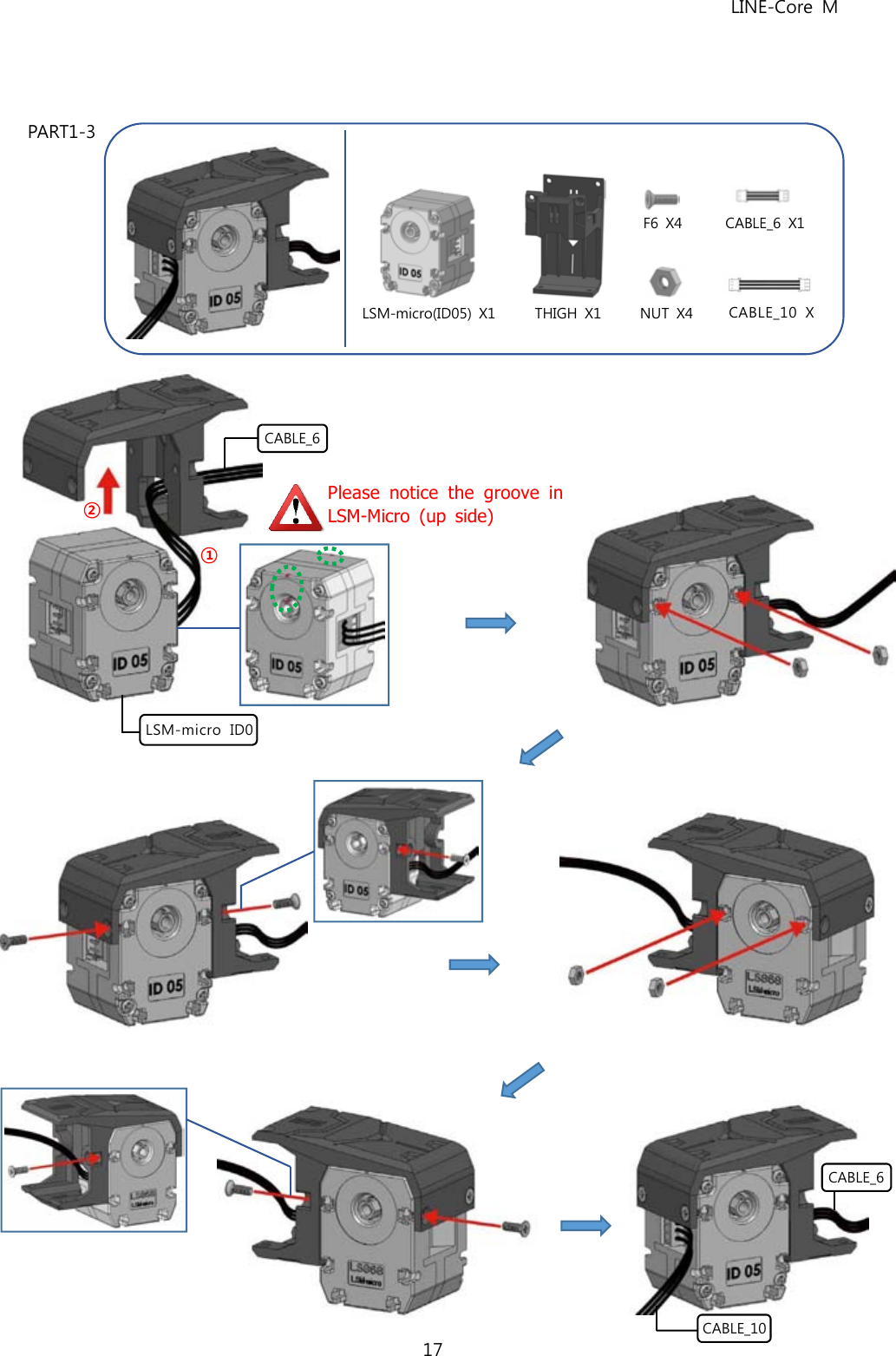
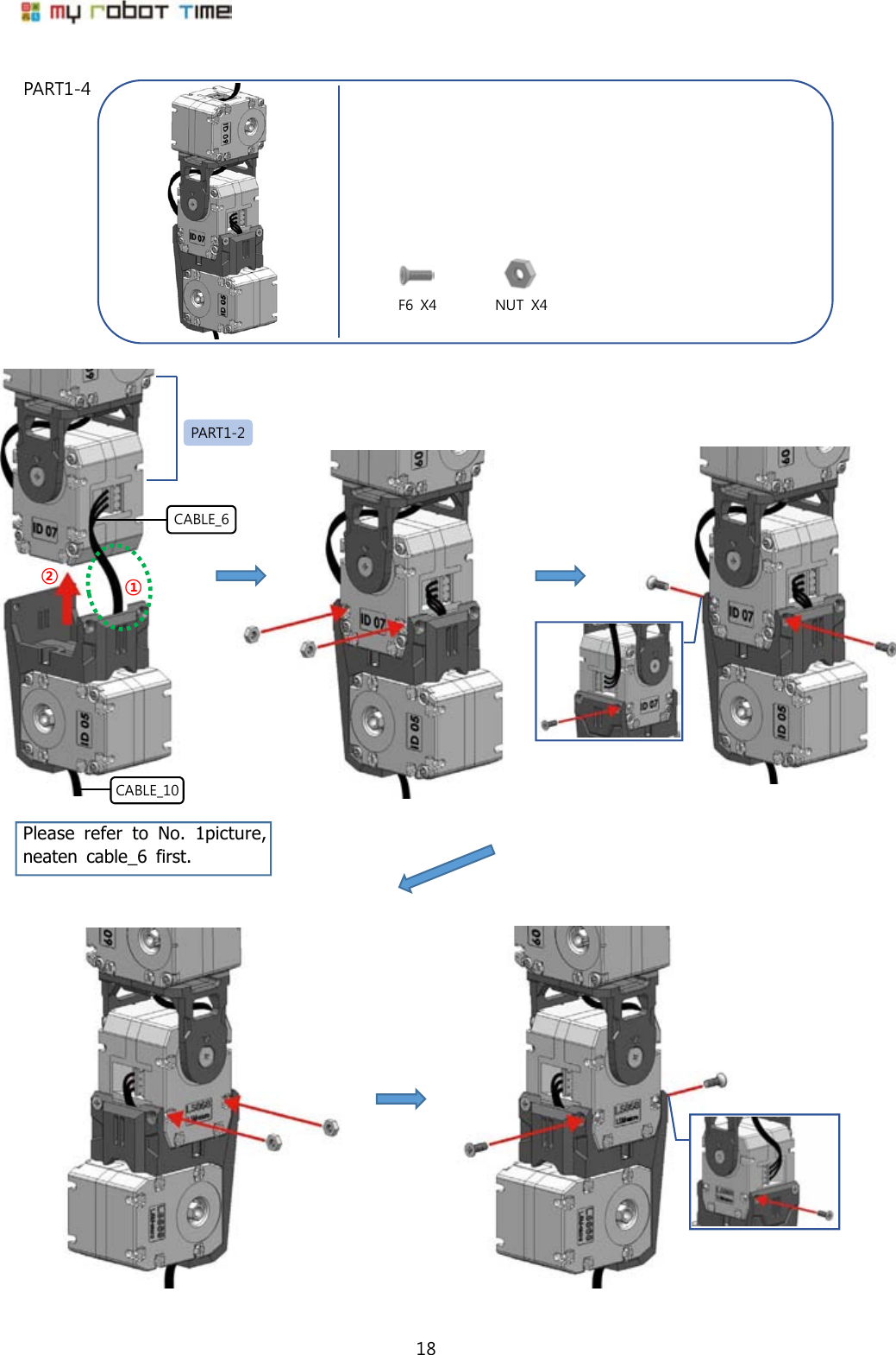
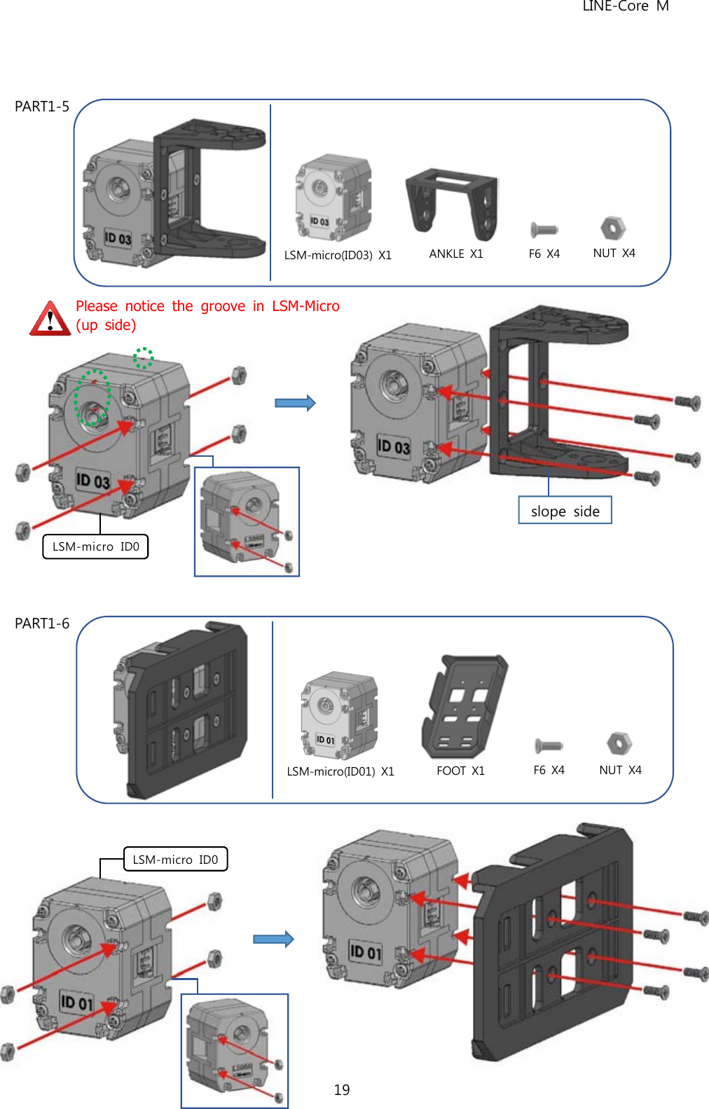
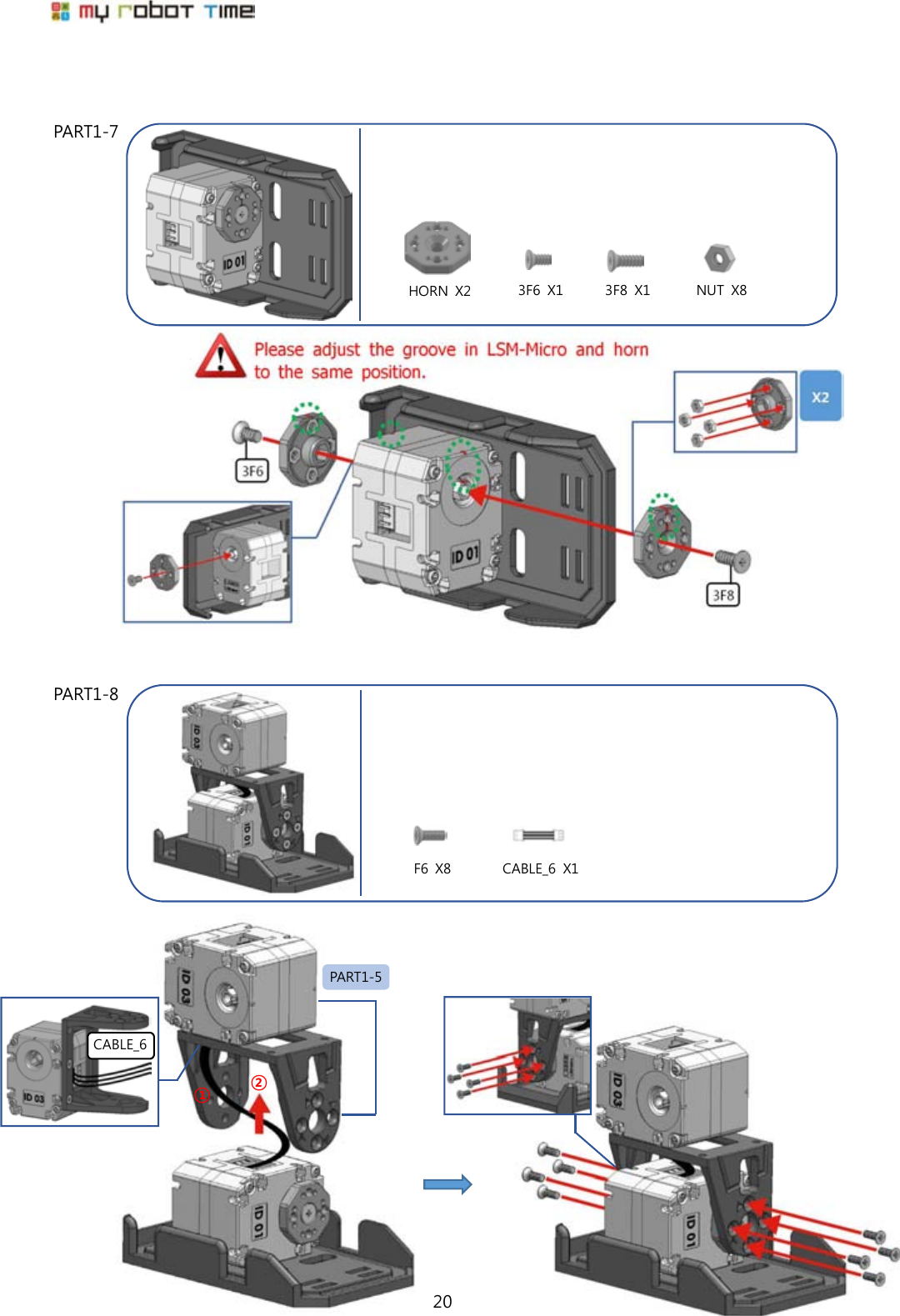
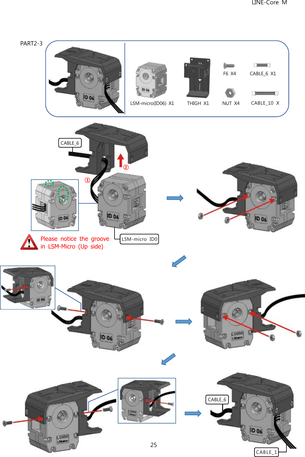
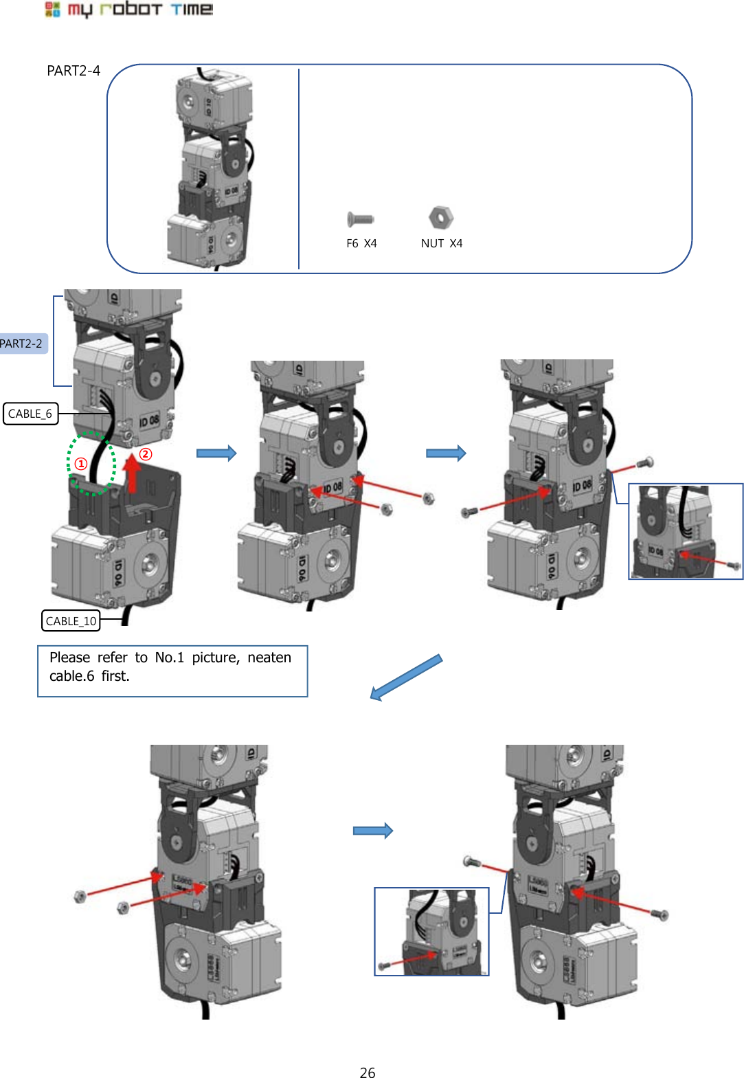
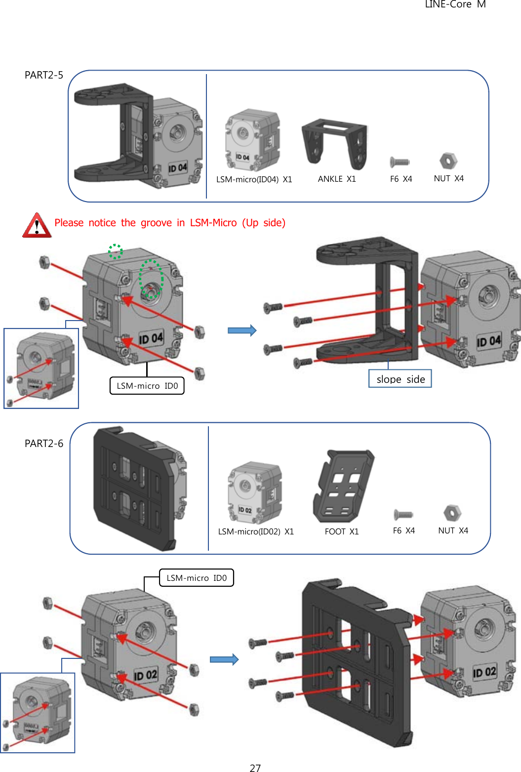
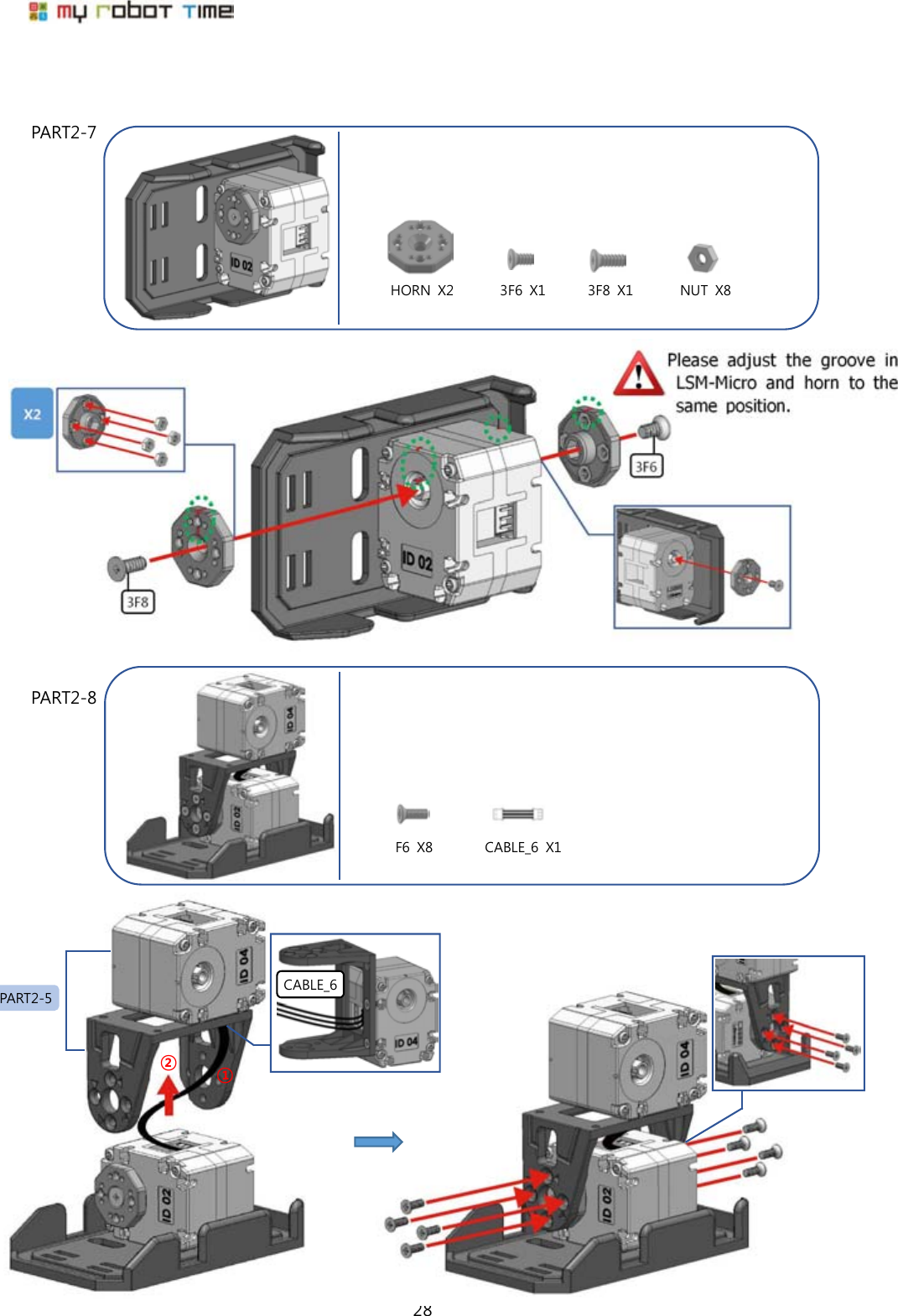
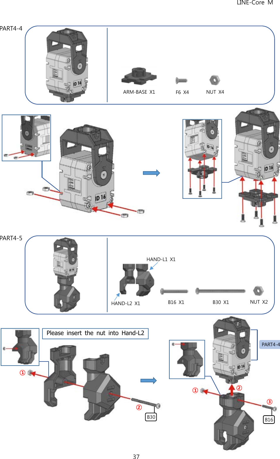
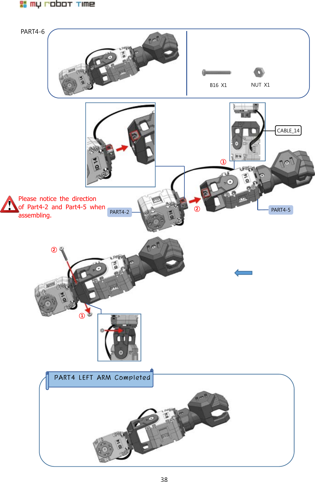
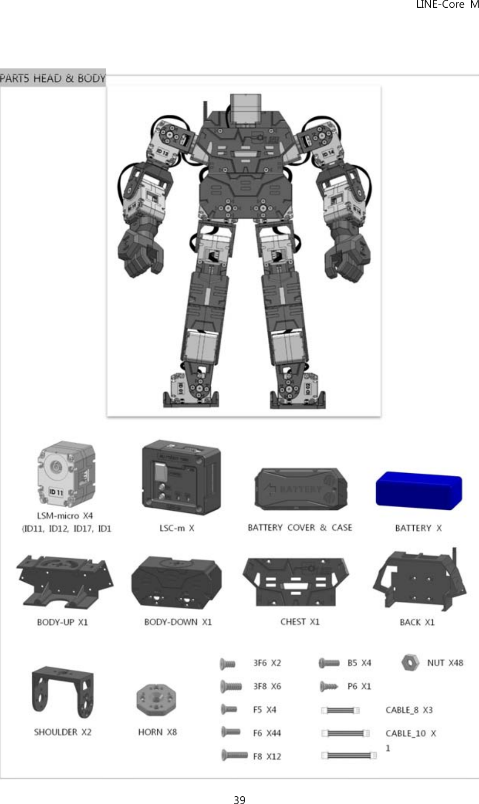
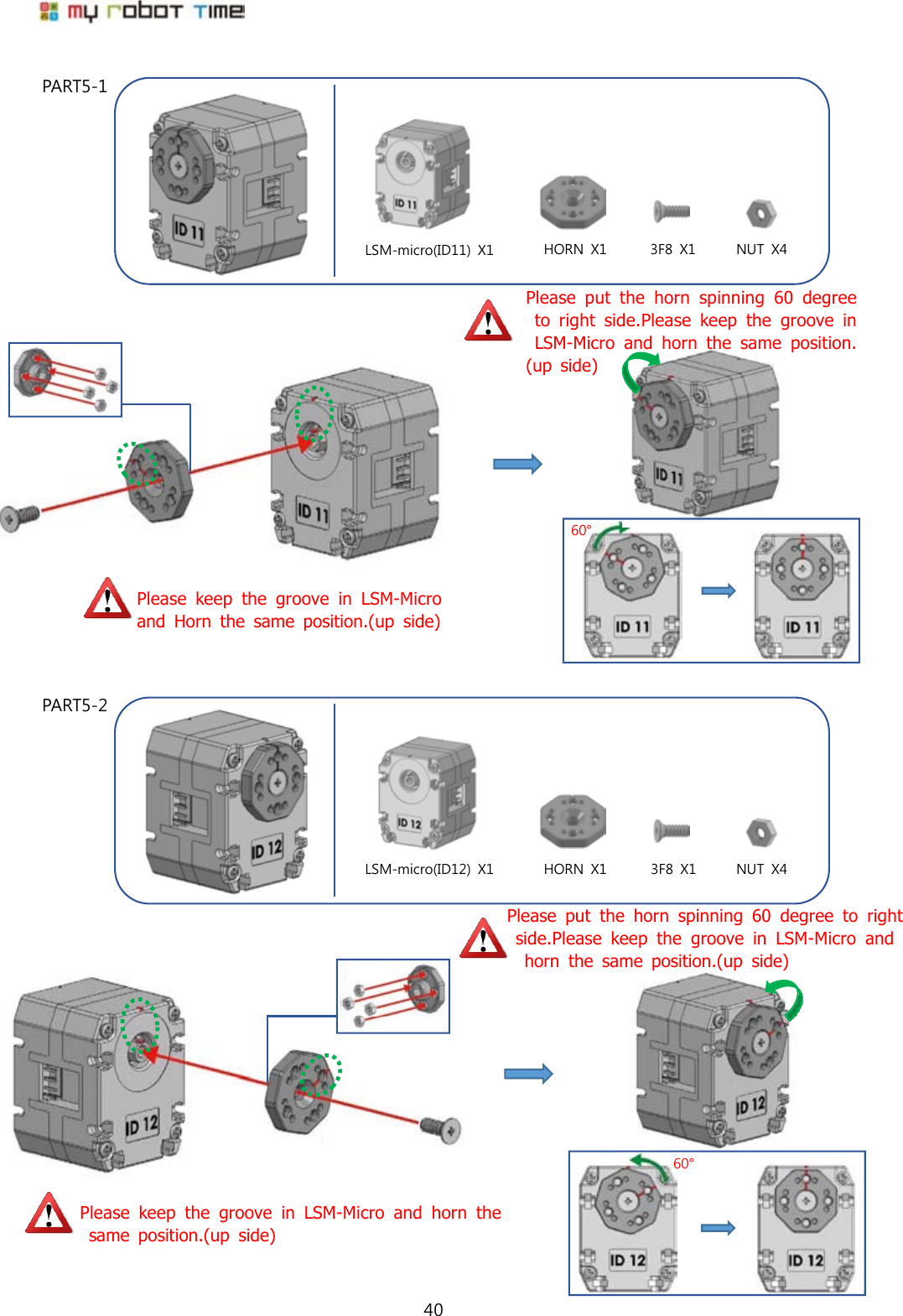
MRT LINE-COREM Bluetooth robot User Manual Users manual
MRT INTERNATIONAL LIMITED Bluetooth robot Users manual
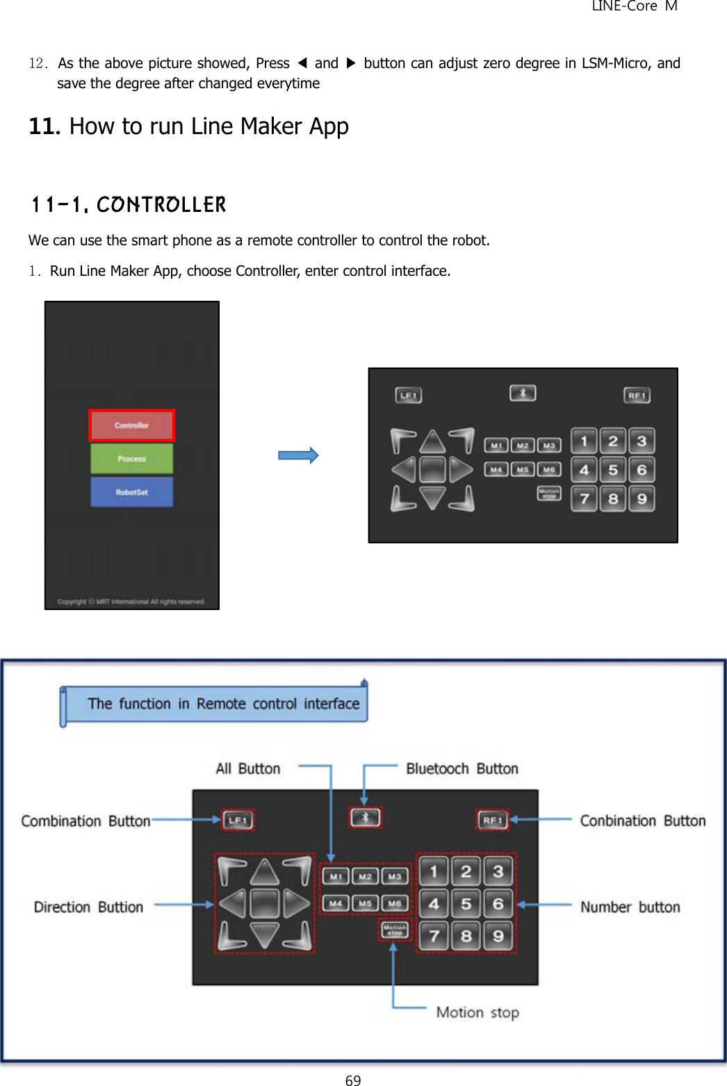
UserManual.wiki
>
MRT
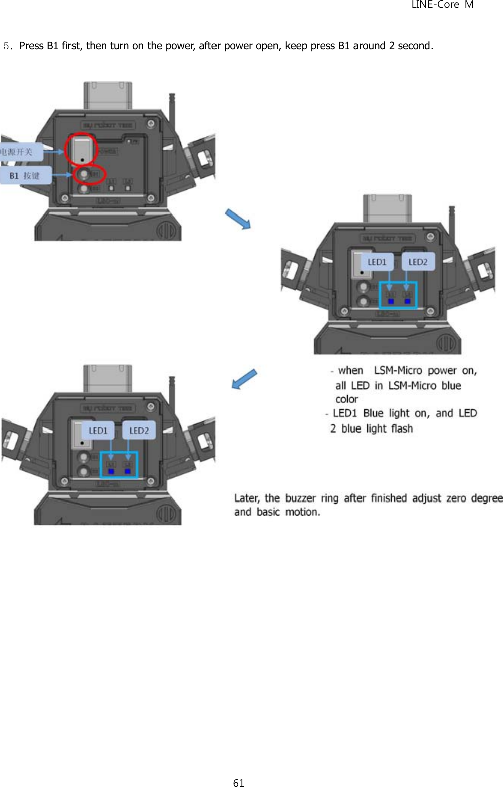
>
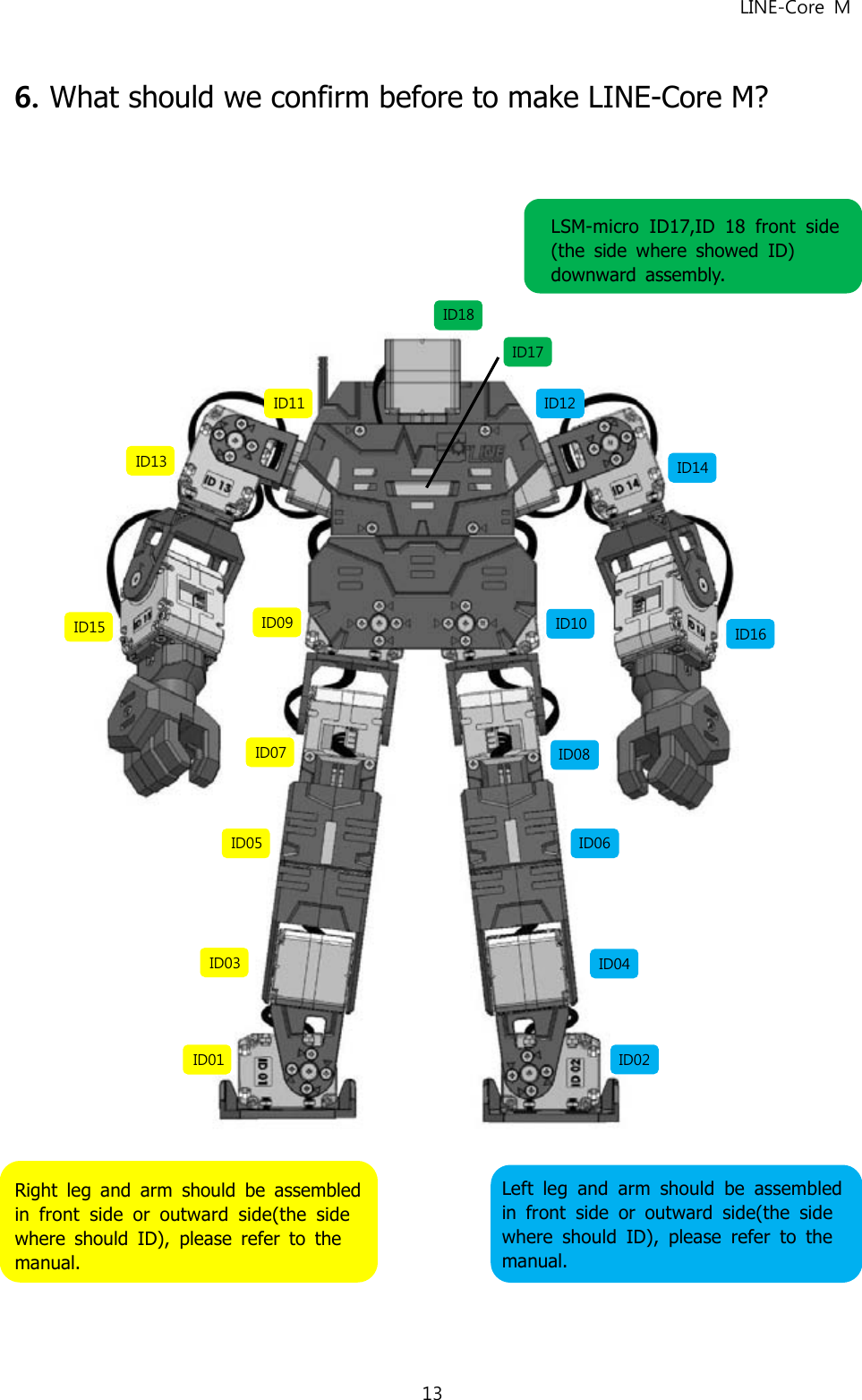
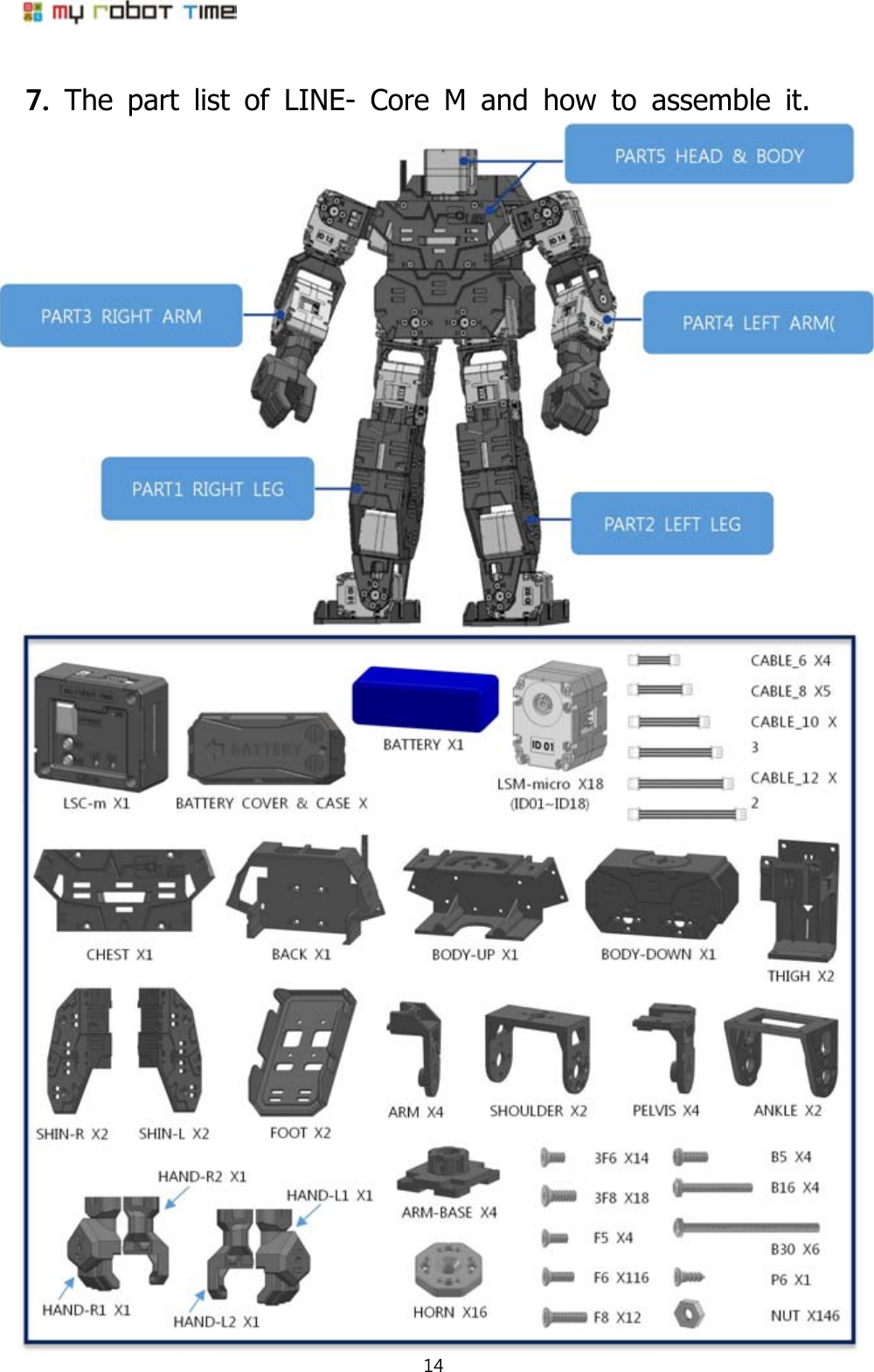
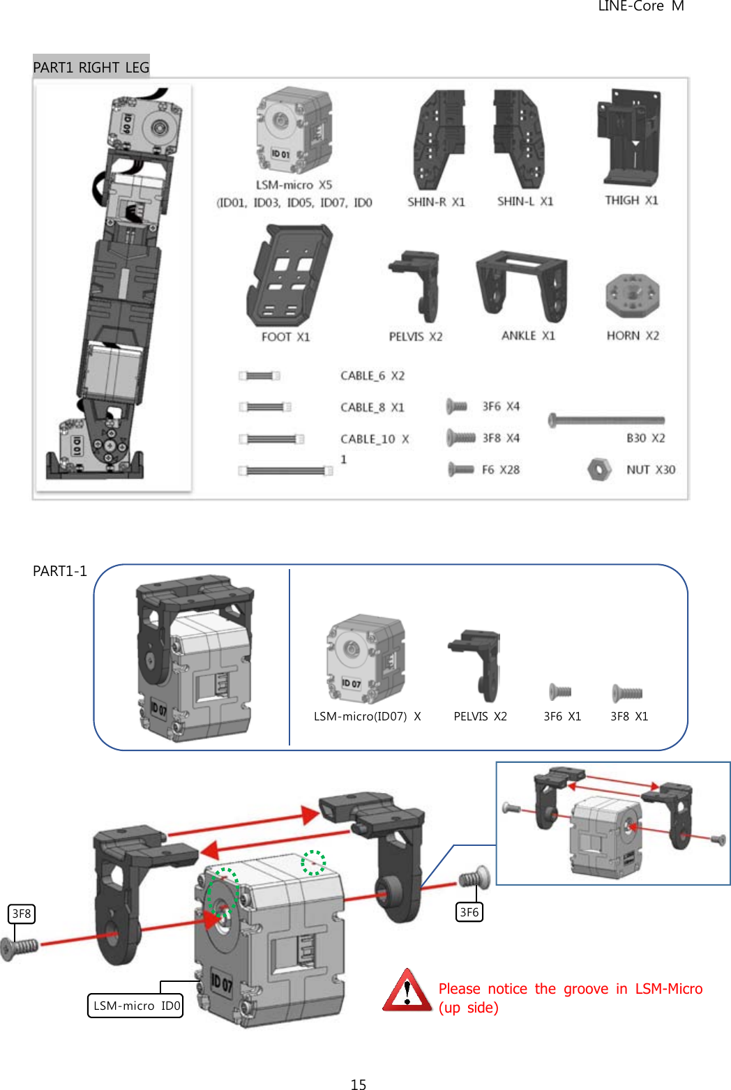
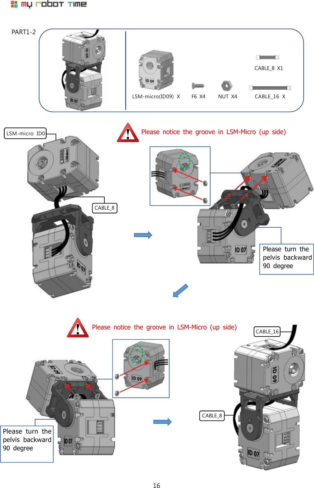
LINE COREM User Manual
Users manual
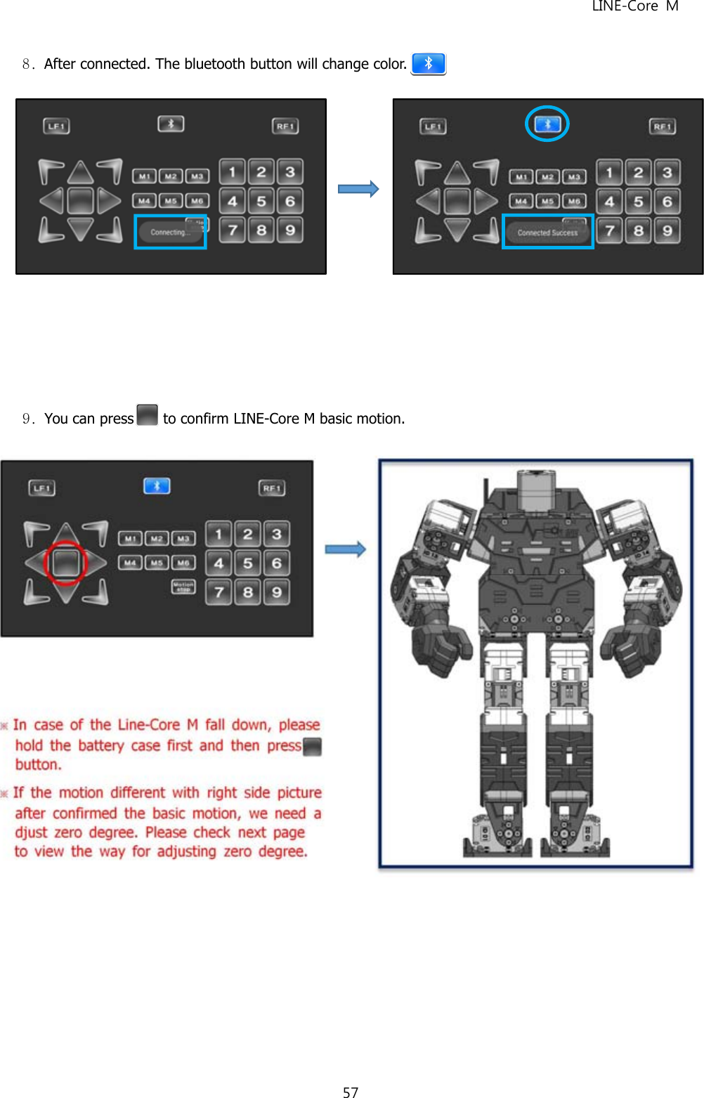
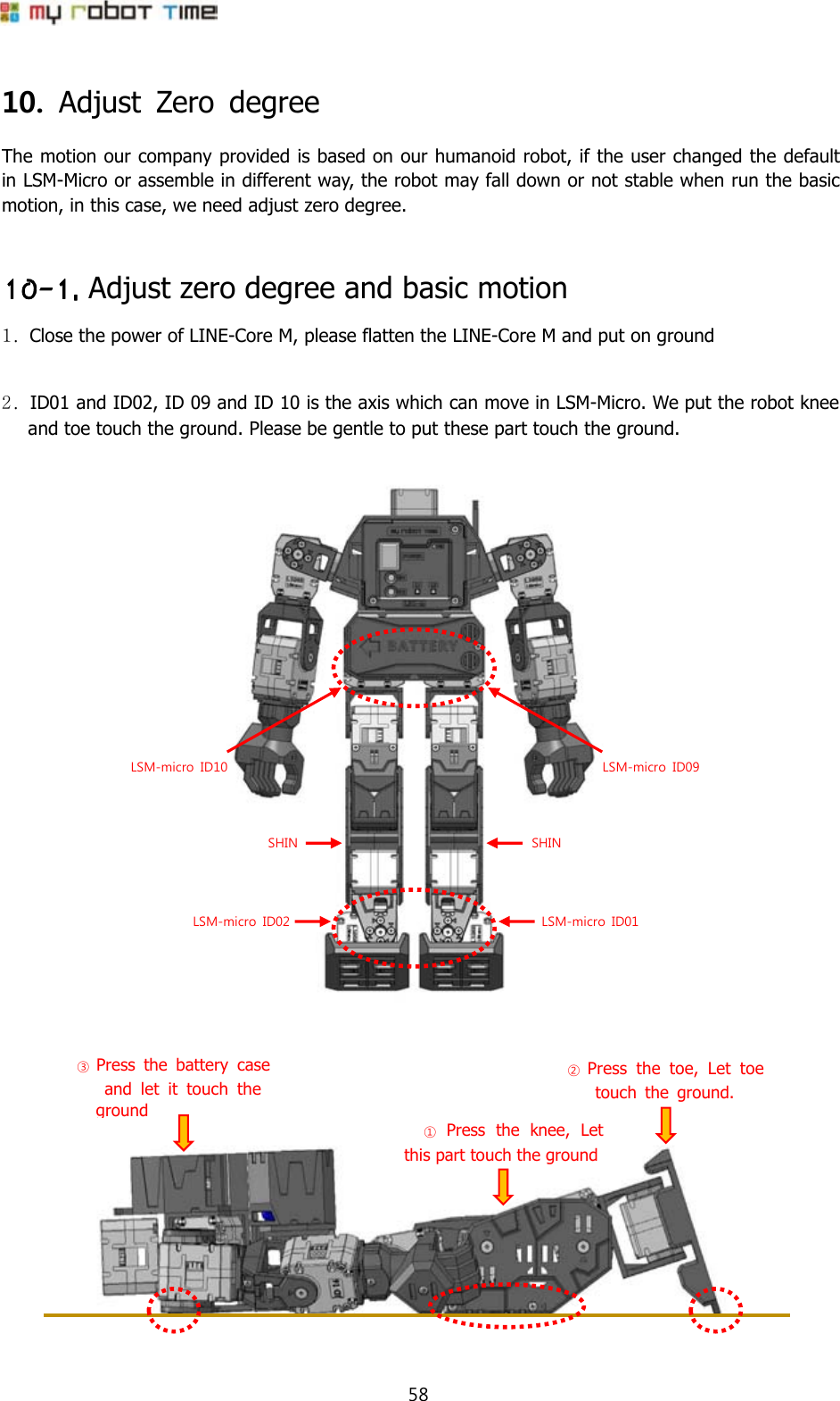
Navigation menu
Upload a User Manual
Namespaces
Wiki Guide
HTML
PDF
Info
Views
User Manual
Discussion / Help
Navigation