Payter P68001 P68 THE ARC User Manual P68 UserManual v0 3x
Payter B.V. P68 THE ARC P68 UserManual v0 3x
UserManual.wiki
>
Payter
>
P68001 User Manual
Users Manual
Navigation menu
Upload a User Manual
Namespaces
Wiki Guide
HTML
PDF
Info
Views
User Manual
Discussion / Help
Navigation
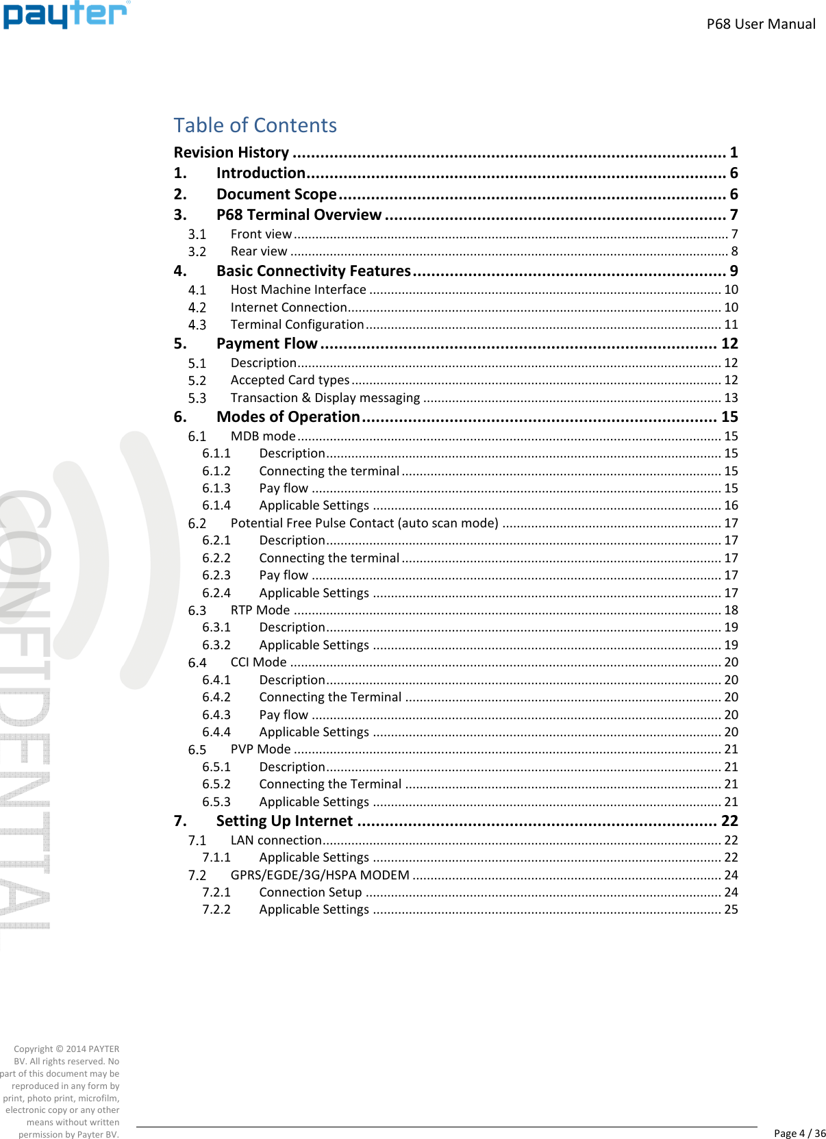
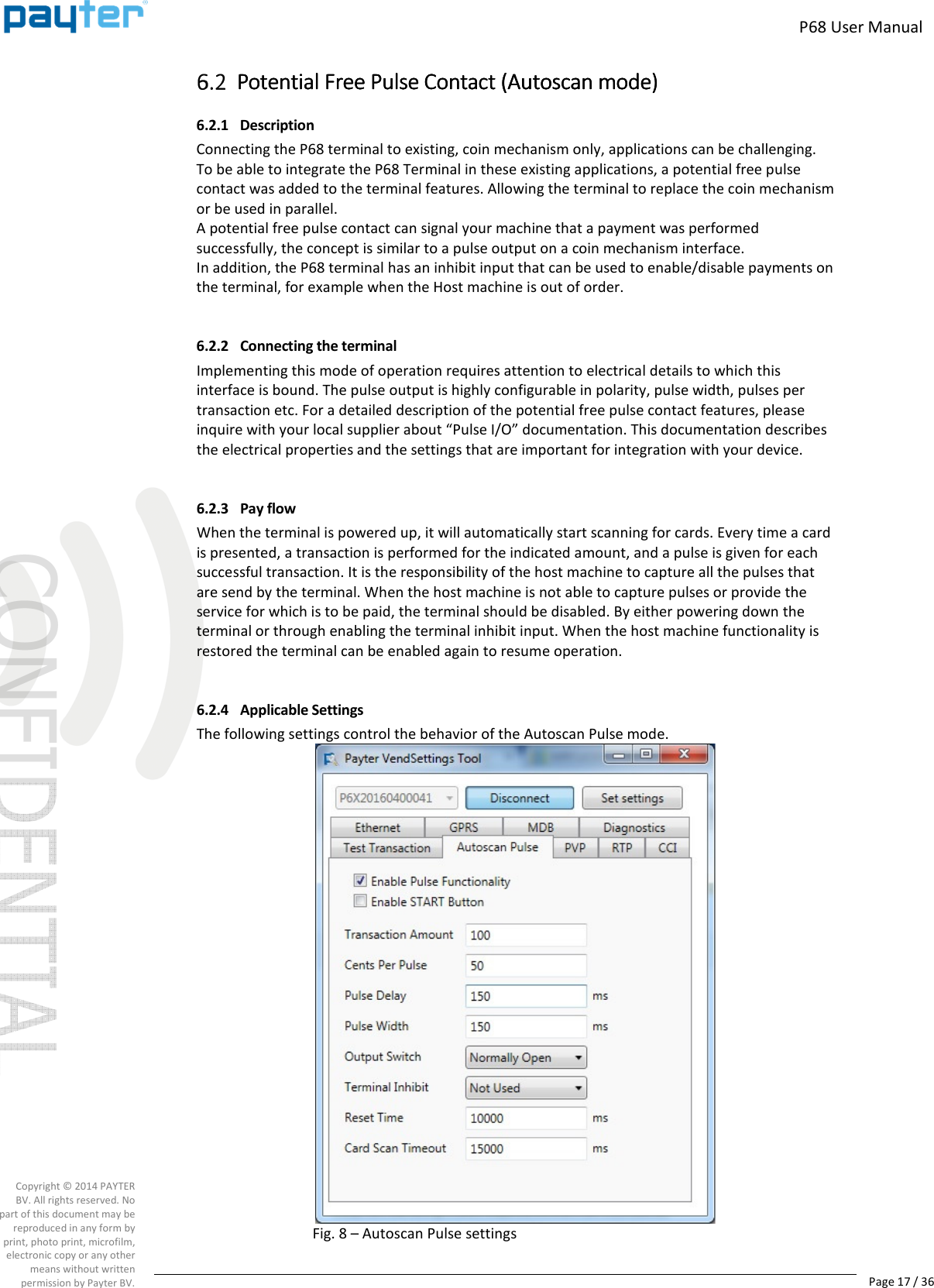
![P68 User Manual Page 16 / 36 Copyright © 2014 PAYTER BV. All rights reserved. No part of this document may be reproduced in any form by print, photo print, microfilm, electronic copy or any other means without written permission by Payter BV. 6.1.4 Applicable Settings The following behavioral settings require attention in MDB mode: Fig. 7 – MDB settings Setting Description MDB Level [1,3] determines the capability level reported to the vending machine. Should be left at 3 unless the terminal and vending machine do not register correctly. Note that level 2 is not supported by the terminal. Session Timeout Indicates the time period, in ms, for selecting a product after the START button is pressed. Note this is only applicable when not in “always idle” mode. Session Amount The amount, in cents, that the Terminal provides as Credit to the vending machine at the start of a session. Note this is only applicable when not in “always idle” mode. Card Scan Timeout Is the time period, in ms, that the terminal scans for a card after the user was prompted to pay. Table 10 - MDB settings](https://usermanual.wiki/Payter/P68001/User-Guide-3277389-Page-16.png)