Proxim Wireless AP8100 Wireless 802.11 abgn Router User Manual ORiNOCO AccessPoints HardwareInstGuide
Proxim Wireless Corporation Wireless 802.11 abgn Router ORiNOCO AccessPoints HardwareInstGuide
Contents
- 1. User Manual
- 2. User Manual - Statements
- 3. User manual rev
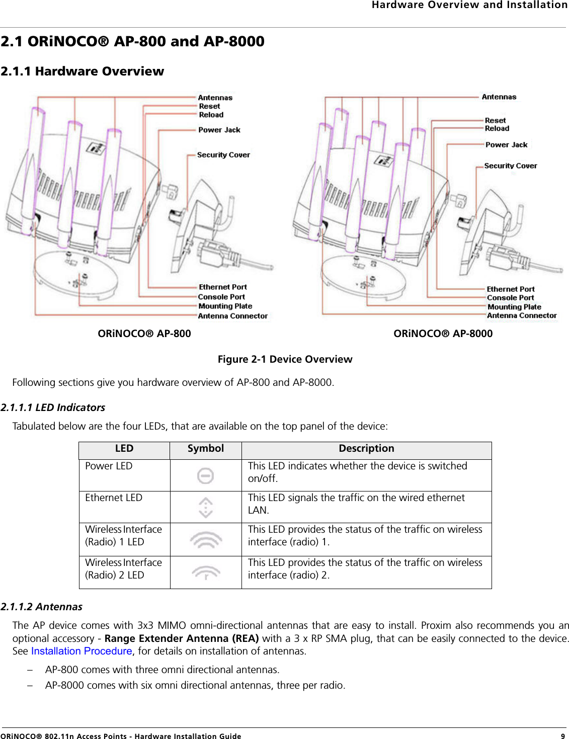
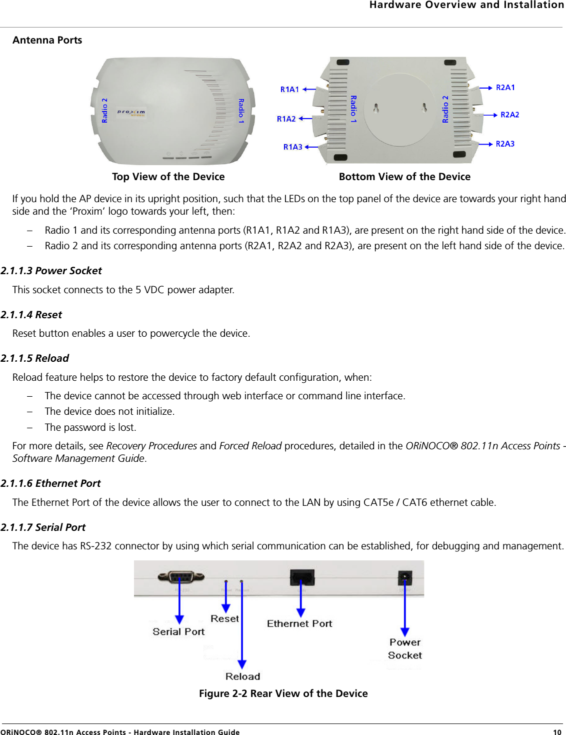
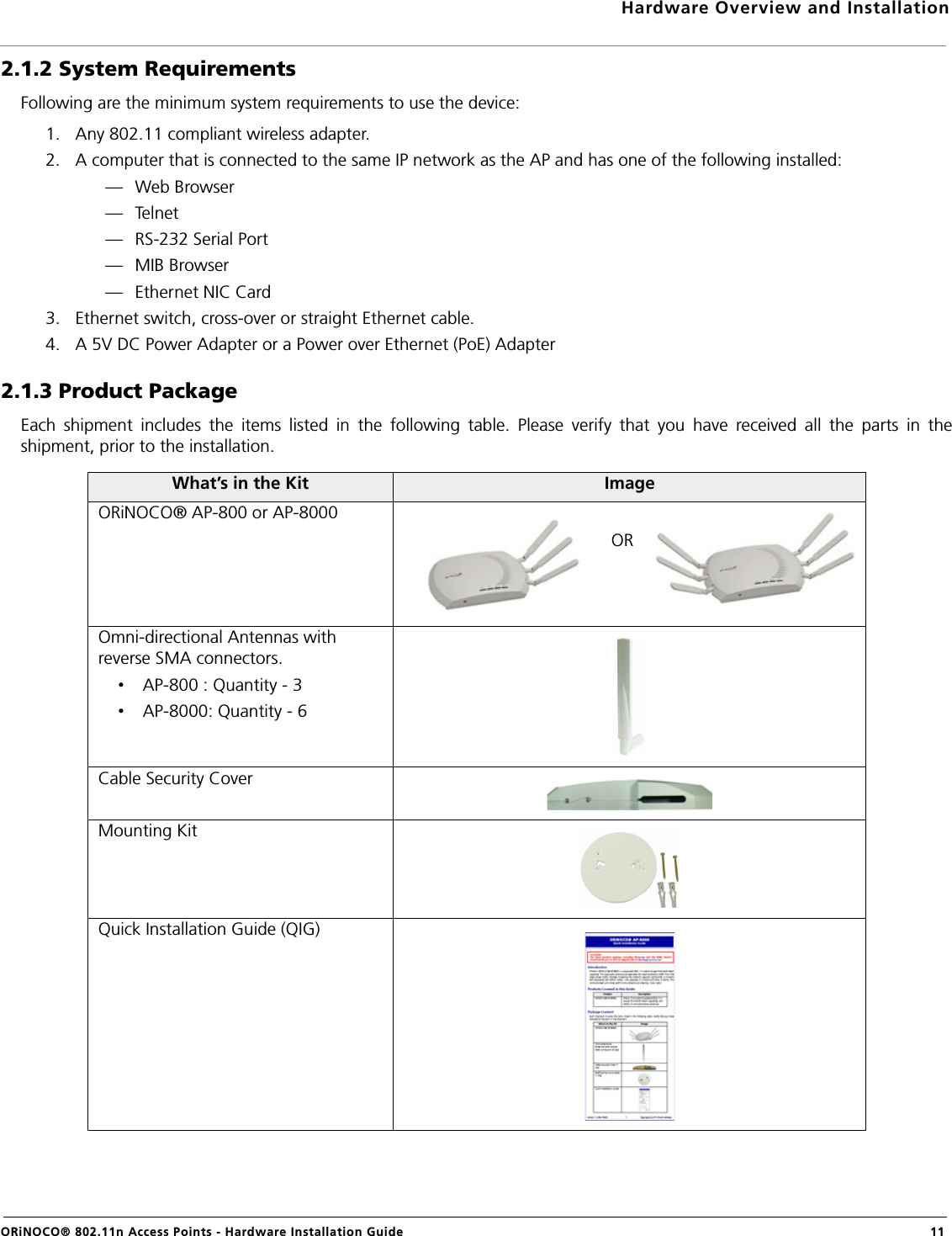
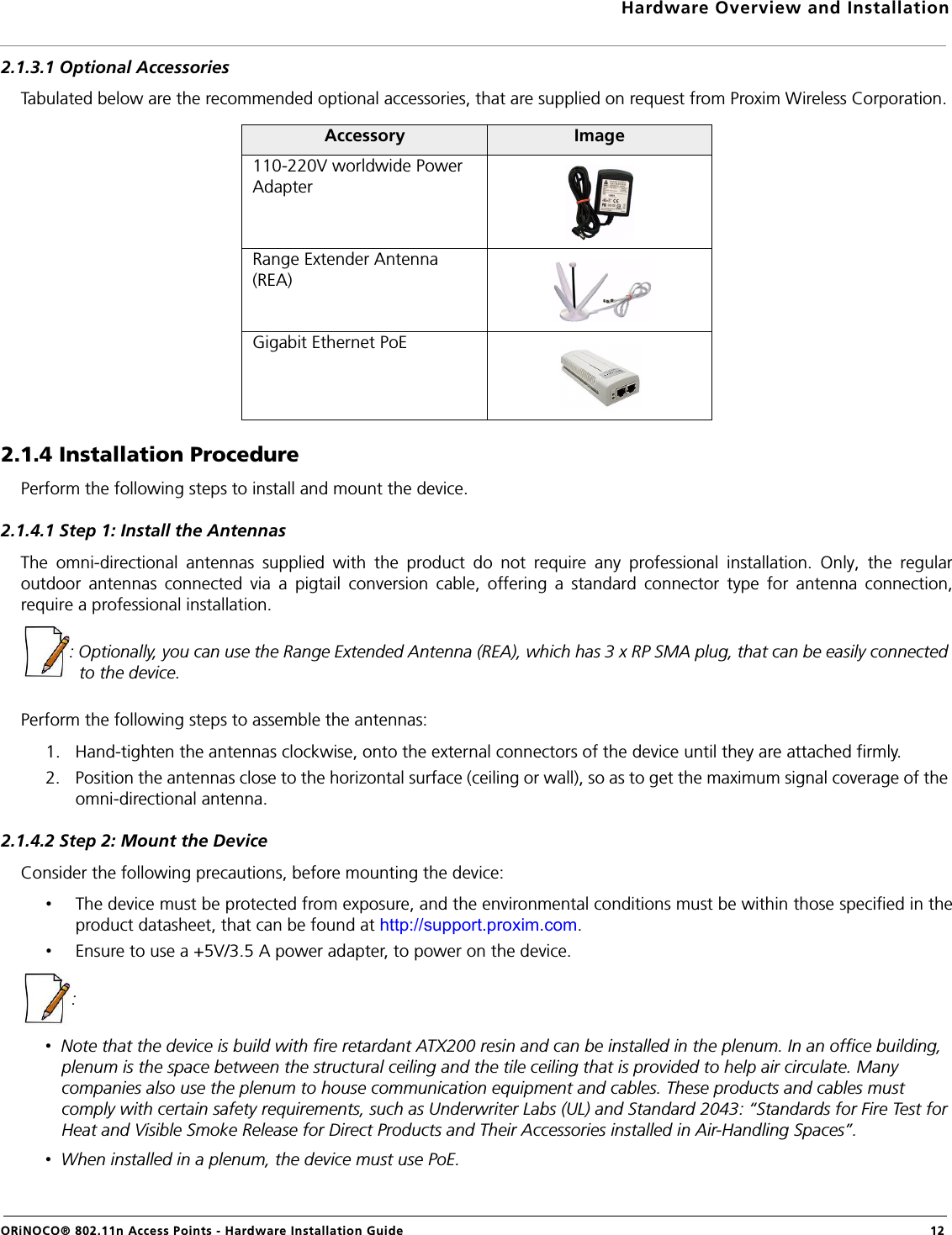
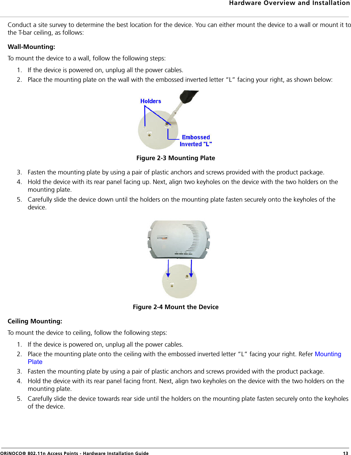
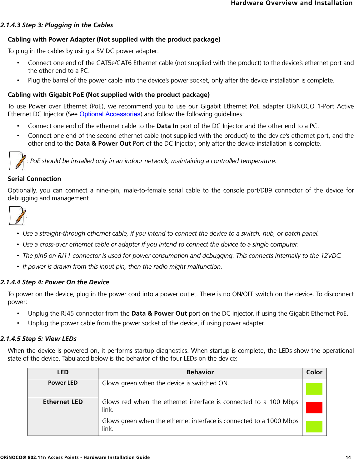
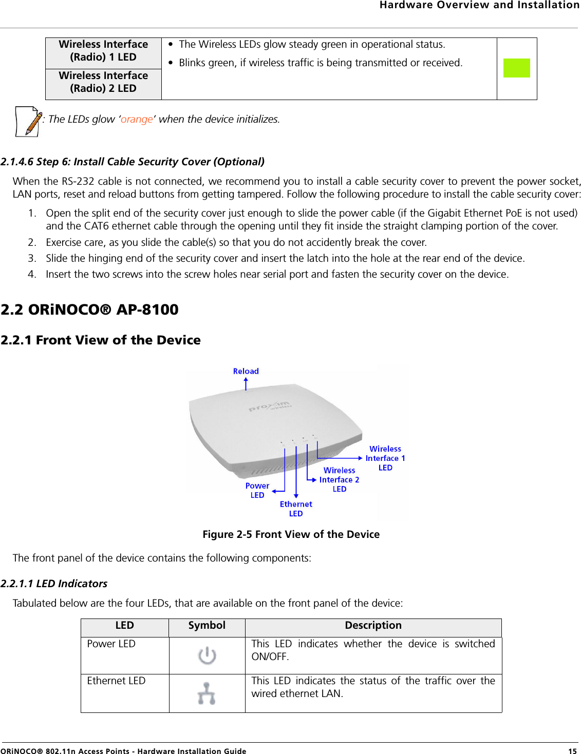
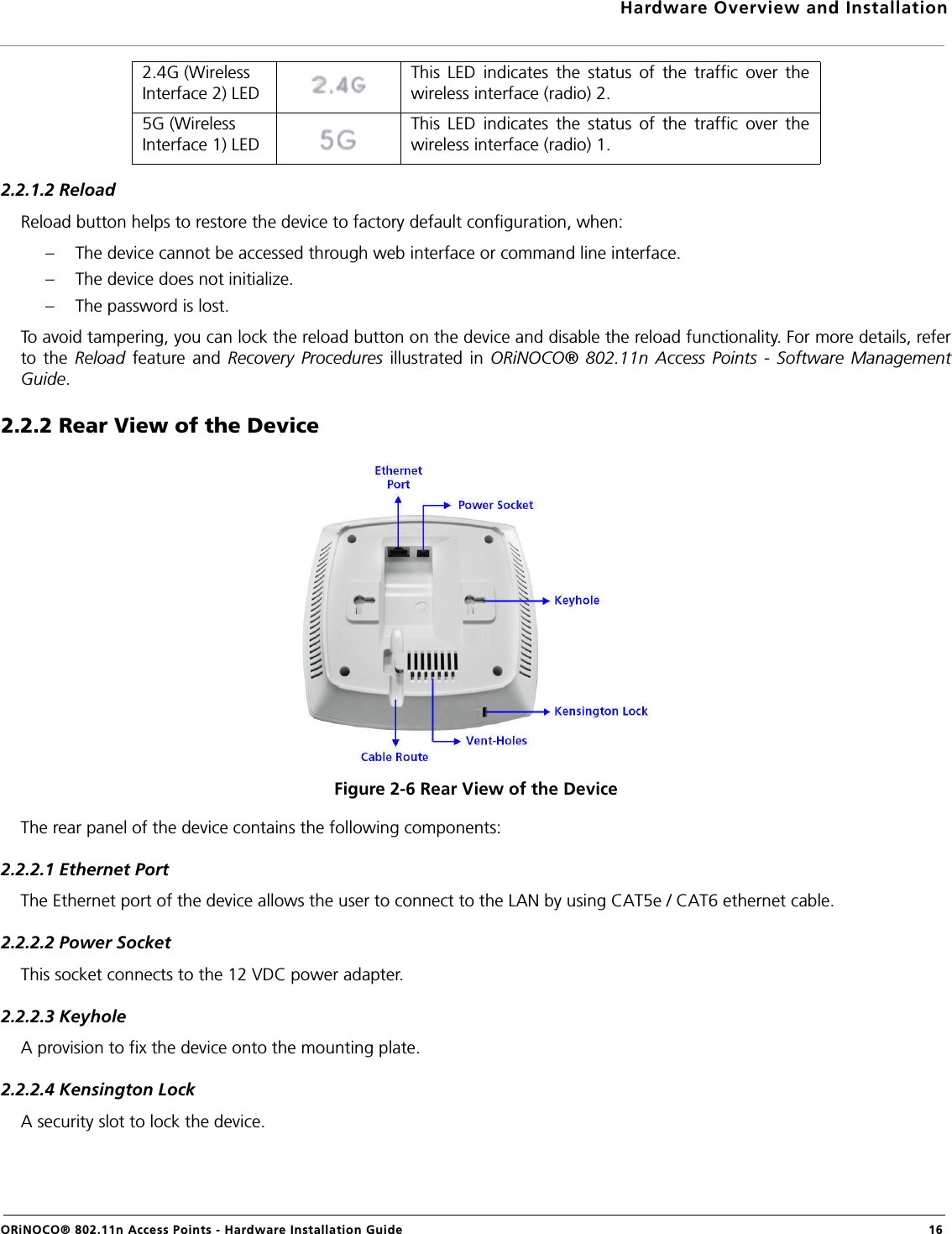
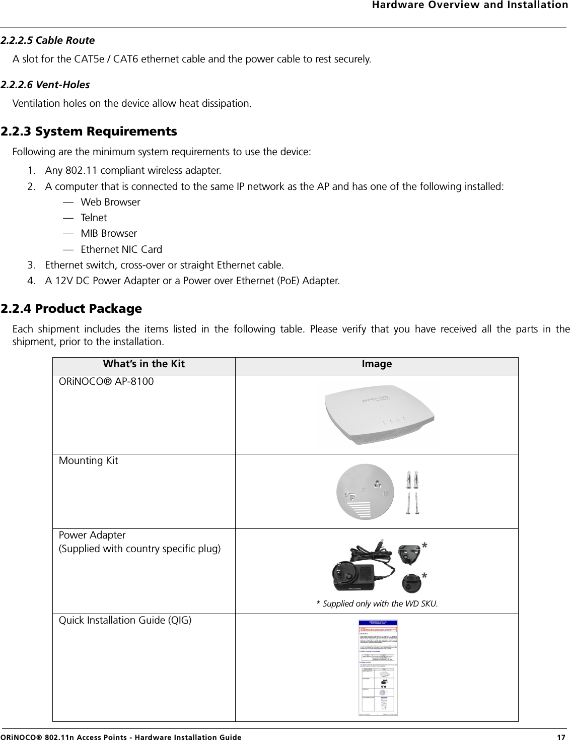
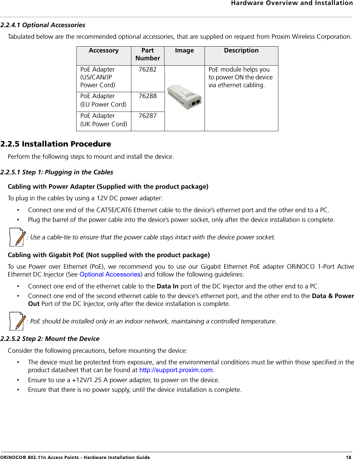
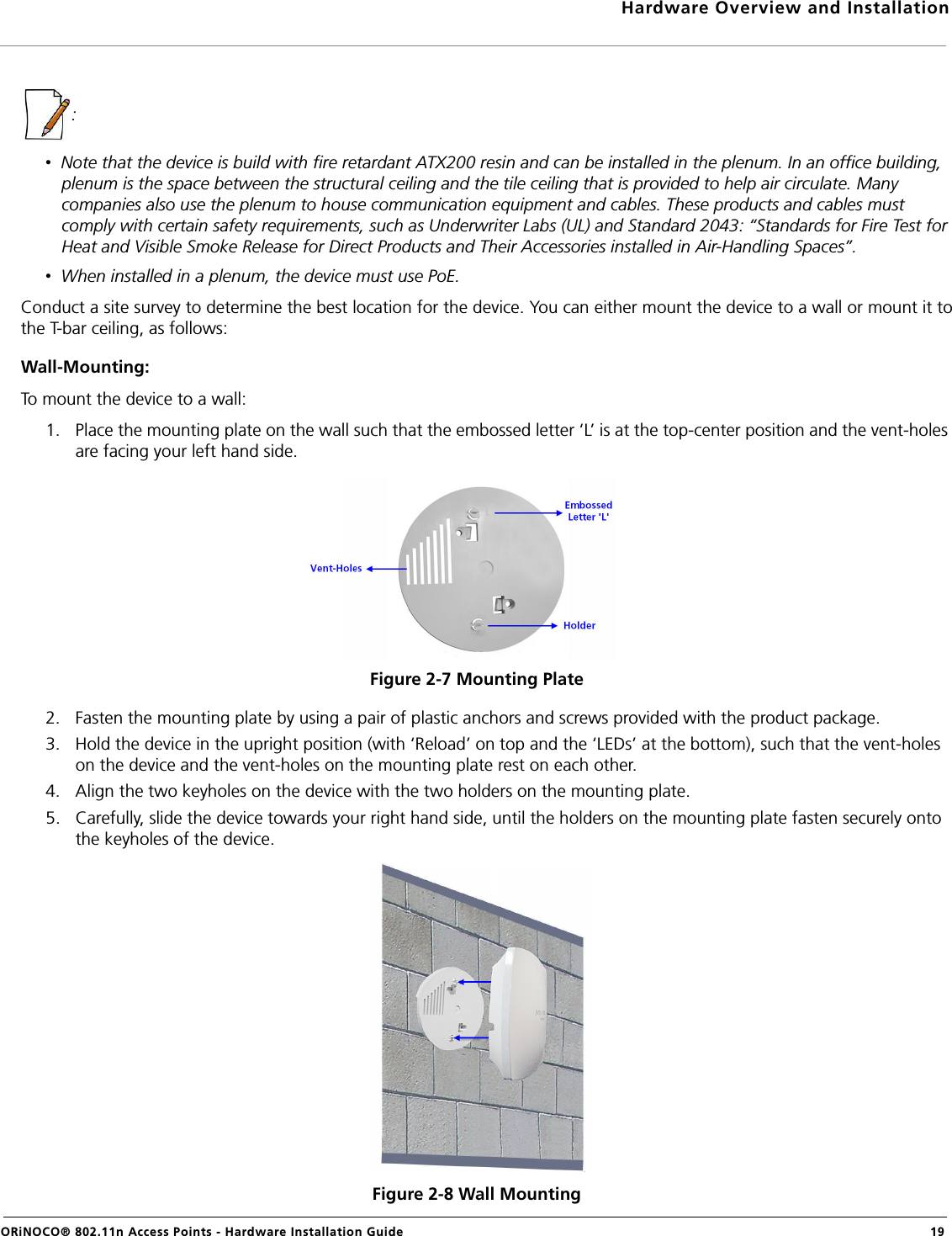
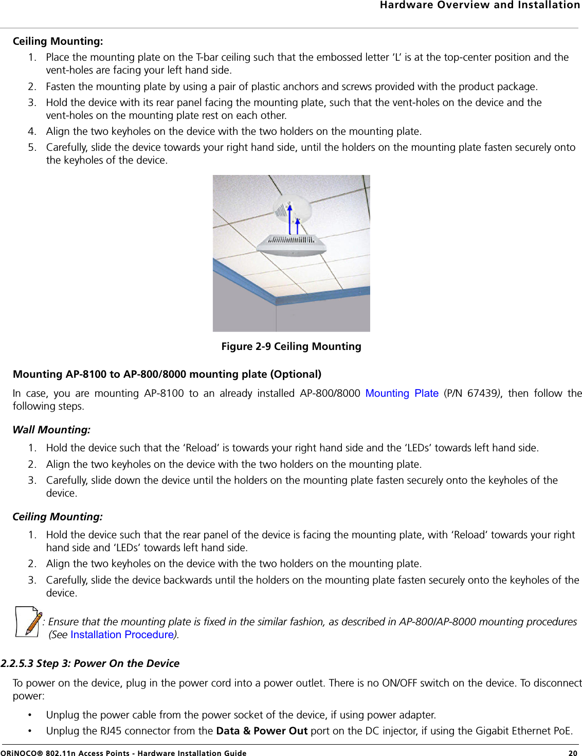
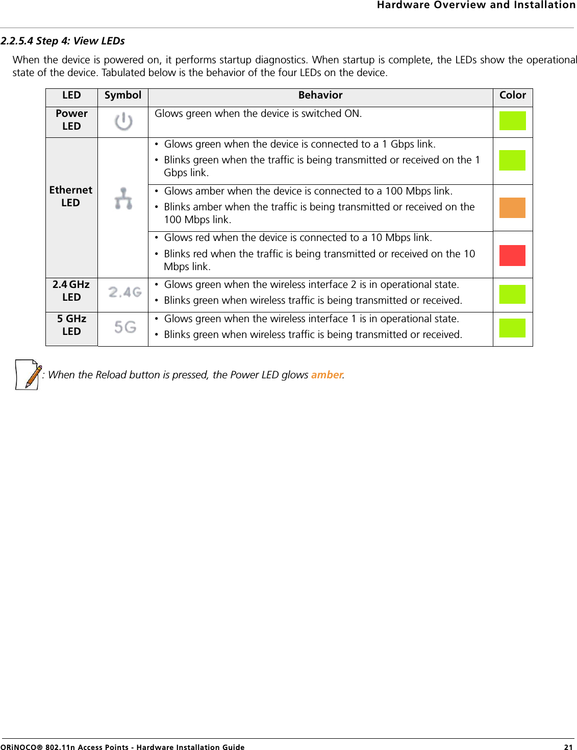
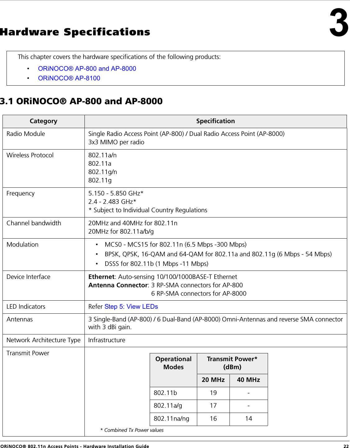
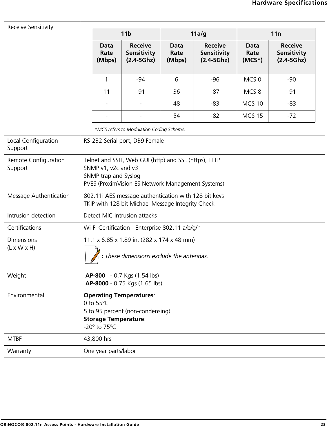
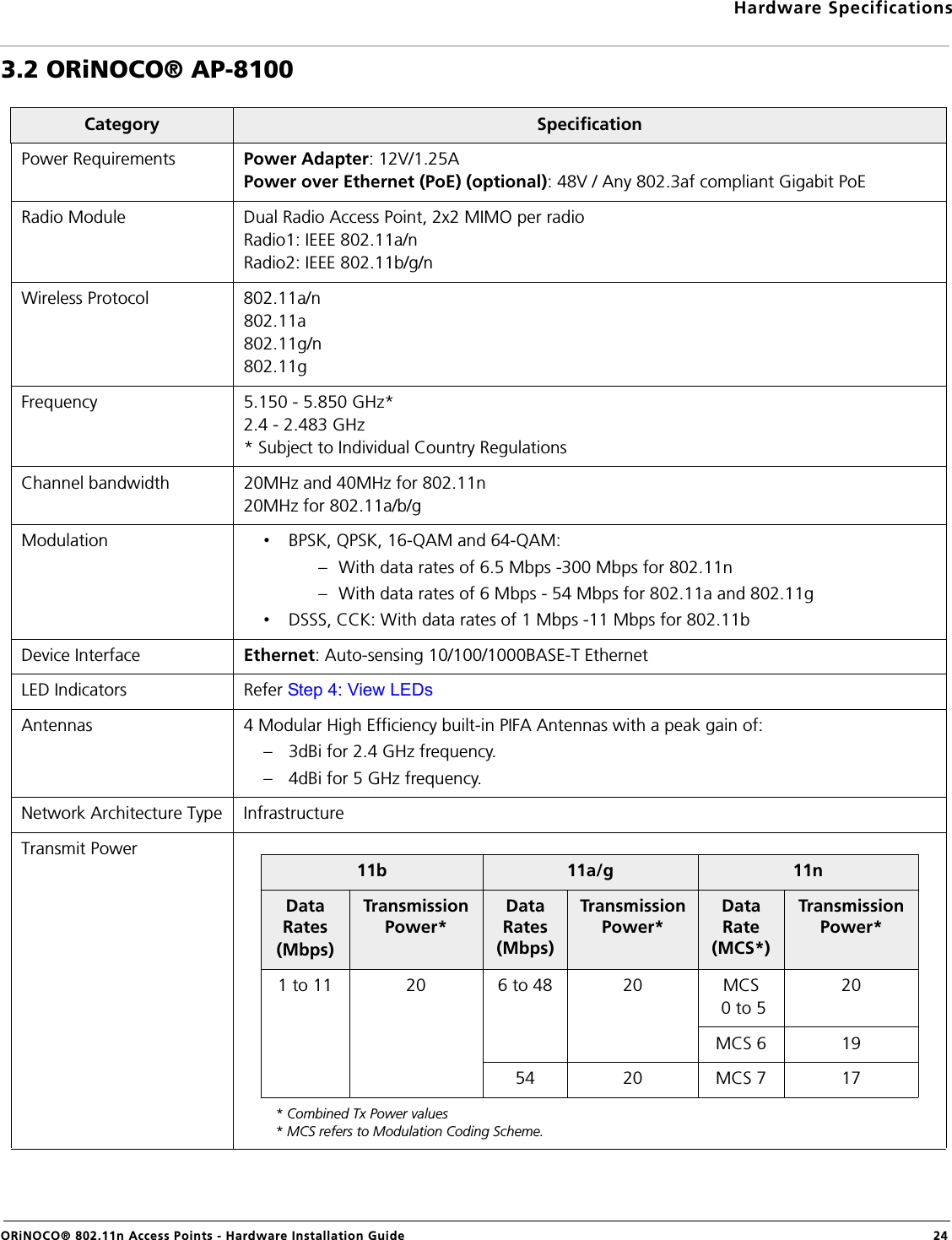
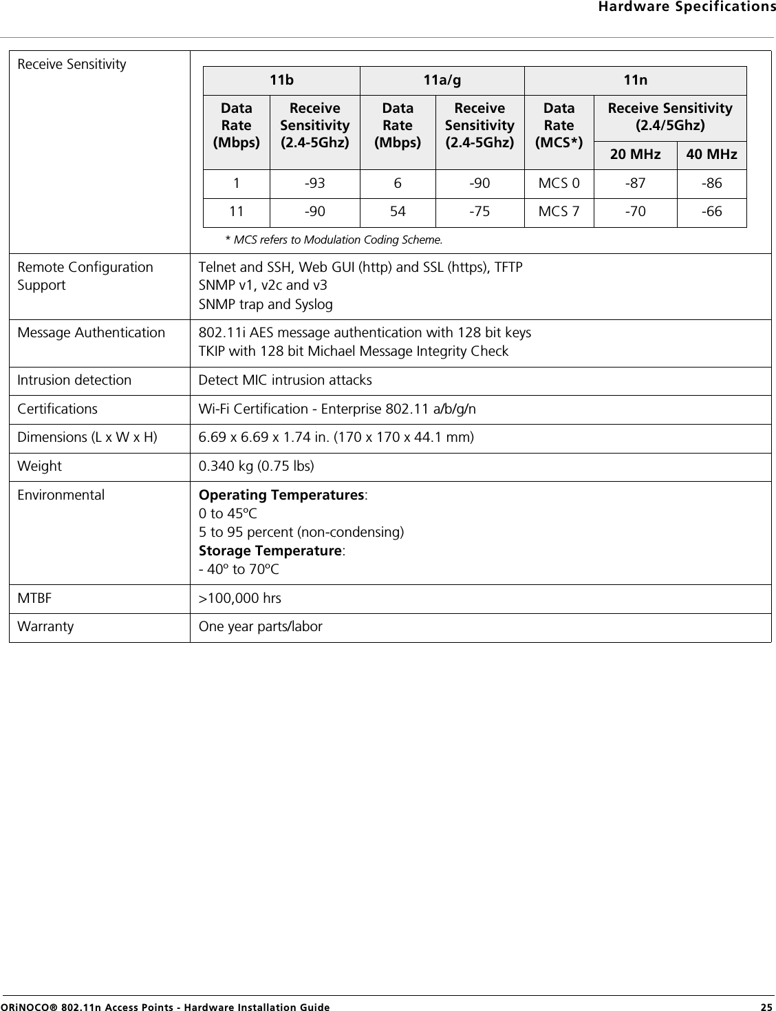
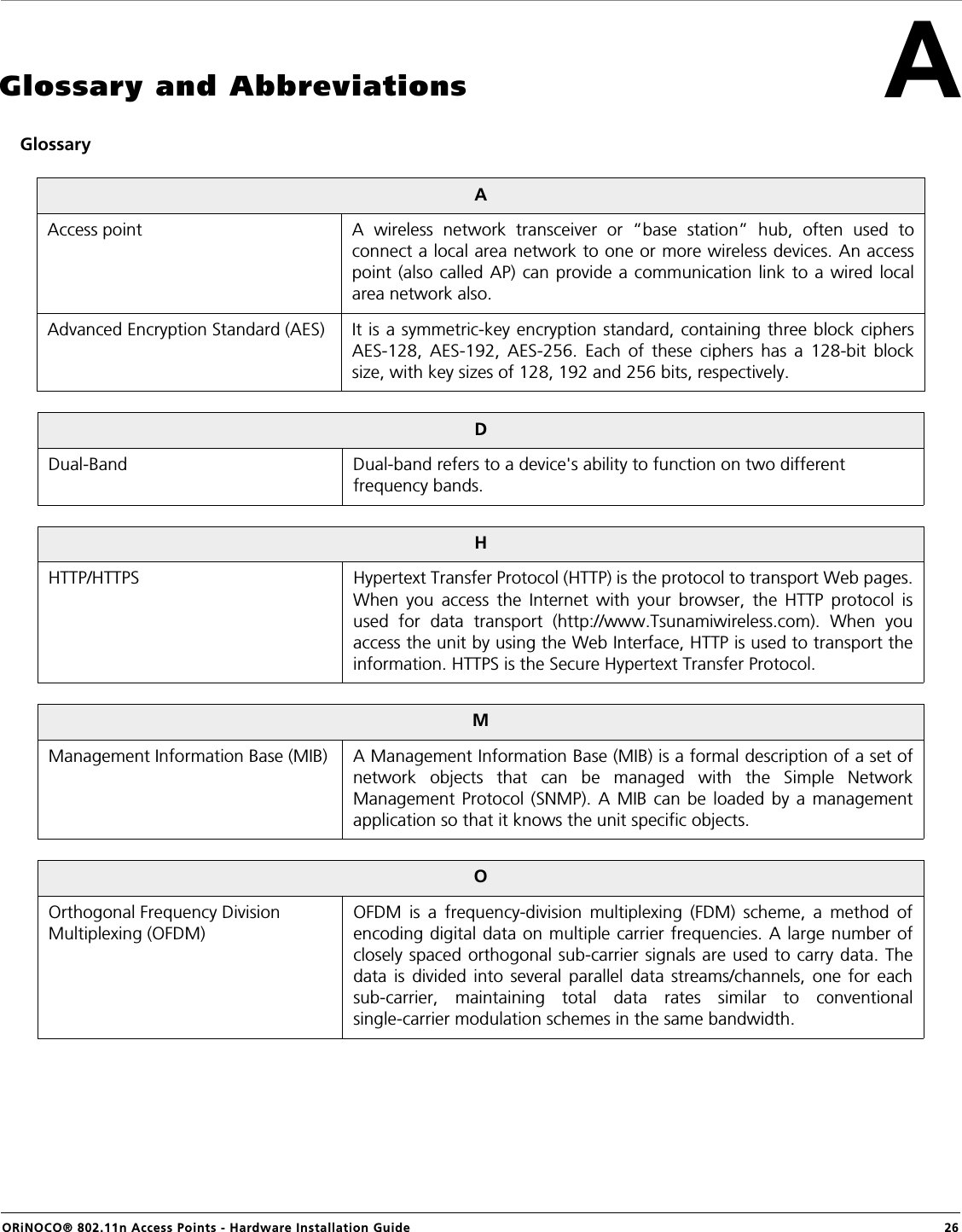
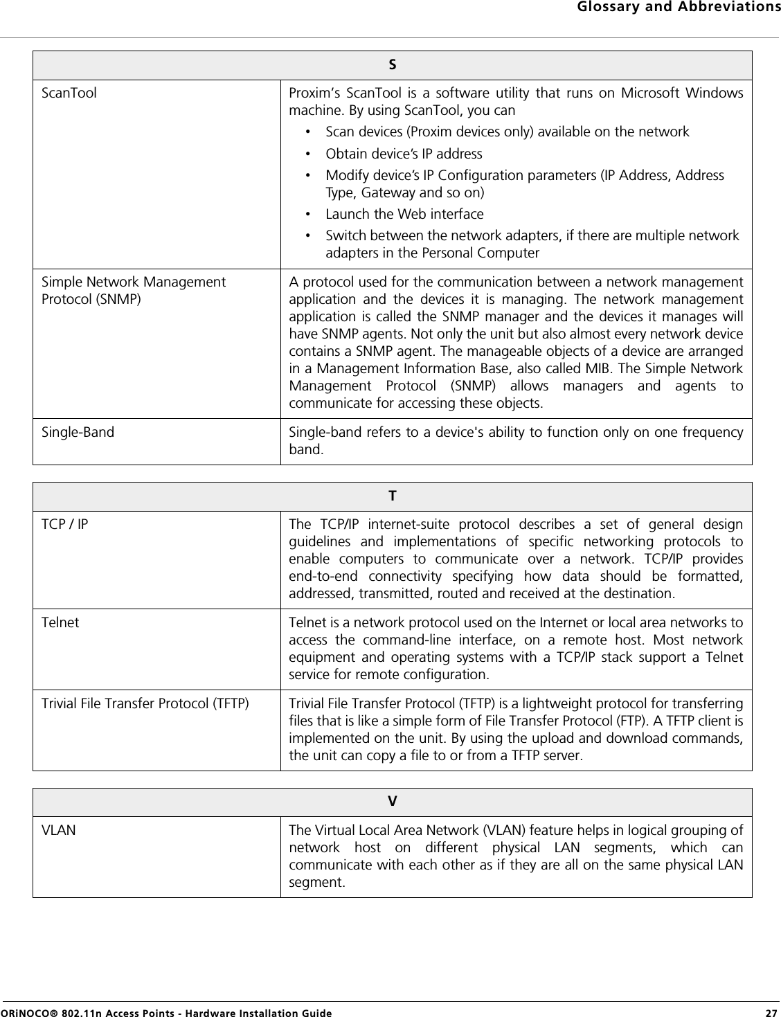
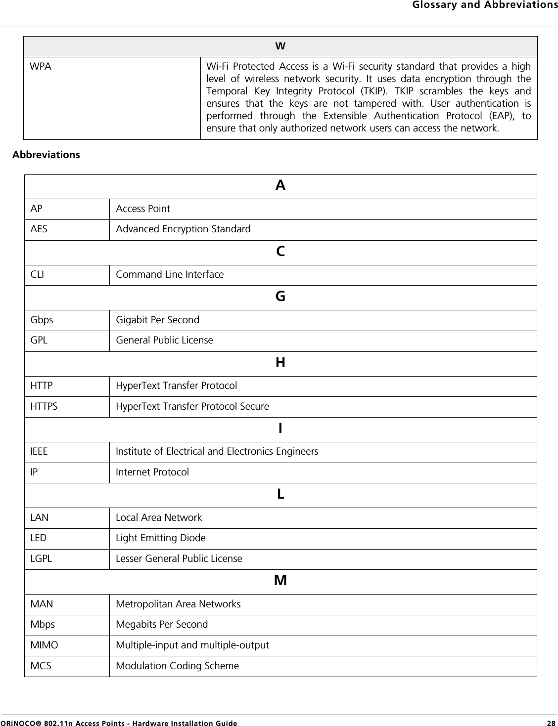
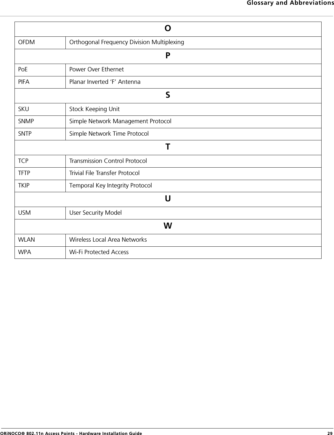
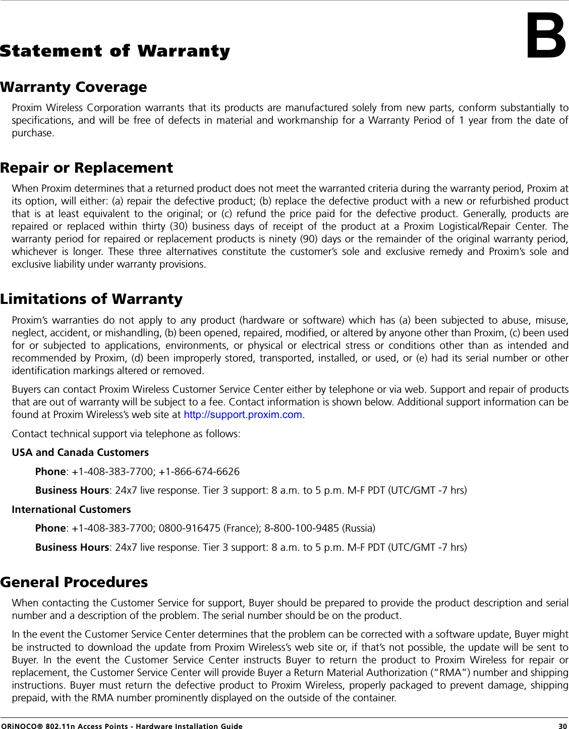
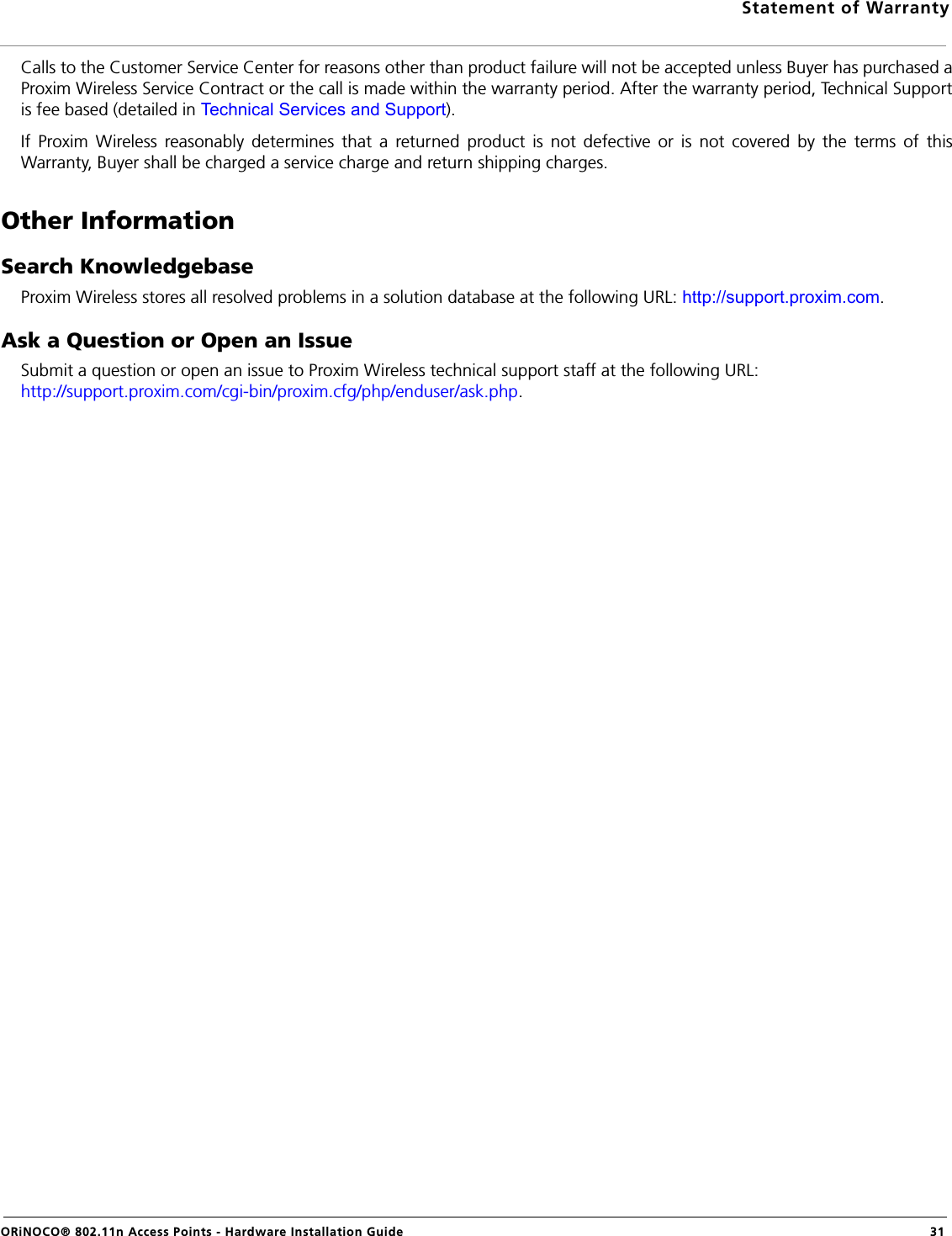
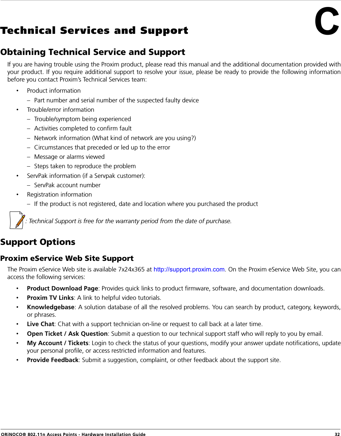
User Manual