Contents
- 1. Users Manual Part 1
- 2. Users Manual Part 2
Users Manual Part 1

Installation and Operation Manual
WinLin
k
™100
0
Point-to-Point Wireless Product
Family
Version 11.1

WinLink 1000
Point-to-Point Wireless TDM/IP
Installation and Operation Manual
Notice
This manual contains information that is proprietary to RADWIN Ltd. ("RADWIN"). No part of this
publication may be reproduced in any form whatsoever without prior written approval by RADWIN
Ltd.
Right, title and interest, all information, copyrights, patents, know-how, trade secrets and other
intellectual property or other proprietary rights relating to this manual and to the WinLink 1000
and any software components contained therein are proprietary products of RADWIN protected
under international copyright law and shall be and remain solely with RADWIN.
WinLink 1000 is a registered trademark of RADWIN. No right, license, or interest to such
trademark is granted hereunder, and you agree that no such right, license, or interest shall be
asserted by you with respect to such trademark.
You shall not copy, reverse compile or reverse assemble all or any portion of the Manual or the
WinLink 1000. You are prohibited from, and shall not, directly or indirectly, develop, market,
distribute, license, or sell any product that supports substantially similar functionality as the
WinLink 1000 based on or derived in any way from the WinLink 1000. Your undertaking in this
paragraph shall survive the termination of this Agreement.
This Agreement is effective upon your opening of the WinLink 1000 package and shall continue
until terminated. RADWIN may terminate this Agreement upon the breach by you of any term
hereof. Upon such termination by RADWIN, you agree to return to RADWIN the WinLink 1000 and
all copies and portions thereof.
For further information contact RADWIN at the address below or contact your local distributor.
International Headquarters RADWIN Ltd. U.S. Headquarters RADWIN Inc.
27 Habarzel Street 900 Corporate Drive
Tel Aviv 69710 Israel Mahwah, NJ 07430 USA
Tel: 972-54-766-00-44 Tel: 1.800.444.7234 (ext. 341)
Fax: 972-3-7662918 Fax: (201) 529-5777
E-mail: support@radwin.com E-mail: support-usa@radwin.com

FCC – User Information
This equipment has been tested and found to comply with the limits for a
Class B digital device, pursuant to Part 15 of the FCC Rules. These limits
are designed to provide reasonable protection against harmful interference
in a residential installation. This equipment generates, uses and can
radiate radio frequency energy and, if not installed and used in accordance
with the instructions, may cause harmful interference to radio
communications. However, there is no guarantee that interference will not
occur in a particular installation. If this equipment does cause harmful
interference to radio or television reception, which can be determined by
turning the equipment off and on, the user is encouraged to try to correct
the interference by one or more of the following measures:
-- Reorient or relocate the receiving antenna.
-- Increase the separation between the equipment and receiver.
-- Connect the equipment into an outlet on a circuit different
from that to which the receiver is connected.
Consult the dealer or an experienced radio/TV technician for help.
Changes or modifications to this equipment not expressly approved by the
party responsible for compliance (RADWIN) could void the user’s authority to
operate the equipment.

It is the responsibility of the installer to ensure that when using the
Warning
outdoor antenna kits in the United States (or where FCC rules apply),
only those antennas certified with the product are used. The use of
any antenna other than those certified with the product is expressly
forbidden in accordance to FCC rules CFR47 part 15.204.
Outdoor units and antennas should be installed ONLY by experienced
installation professionals who are familiar with local building and safety
codes and, wherever applicable, are licensed by the appropriate
Warning
government regulatory authorities. Failure to do so may void the
WinLink-1000 warranty and may expose the end user or the service
provider to legal and financial liabilities. RADWIN and its resellers or
distributors are not liable for injury, damage or violation of regulations
associated with the installation of outdoor units or antennas.
FCC Notation for Indoor Units IDU-E and IDU-C
Concerning all models and configurations
This device complies with part 15 of the FCC Rules. Operation is subject
to the following two conditions:
(1) This device may not cause harmful interference, and
(2) this device must accept any interference received, including
interference that may cause undesired operation.

Quick Start Guide
Installation of WinLink 1000 should be carried out only by a qualified
technician. If you are familiar with WinLink 1000, use this guide to
prepare the units for operation. If you are not familiar with WinLink
1000, please read the Installation and operation Manual carefully.
1. Equipment Required
The following is a list of equipment required for installing a WinLink
1000 link:
• RJ-45 crimp tool (if pre-assembled cable is not used)
• Drill (for wall mounting only)
• IDU and ODU grounding cables
• 13 mm (½″) spanner/wrench
• ODU to IDU cable if not ordered (outdoor class, CAT-5e, 4 twisted
pairs)
• Cable ties
• Laptop running Windows 2000 or Windows XP.
2. Before the Installation
1. Verify that all equipment and tools are available.
2. Install the WinLink 1000 software on the laptop; the installation
takes several minutes.
The software installation leaves the WinLink 1000 Manager icon
on the desktop.
3. BRS systems only - Activate the link.
WinLink 1000 Before the Installation 1

Quick Start Guide Installation and Operation Manual
3. Installing the WinLink 1000 Units
Æ To install the ODU:
1. At site A, route the ODU cable from the ODU location (on the roof)
to the IDU location (inside the building). The maximum length is
100m.
2. Mount the ODU unit to the mast or wall, using the mounting kit and
mounting instructions.
Note
Do not tightly secure the ODU until the alignment process is complete
When installing the ODU is important to check that there are no direct
obstructions in front of the ODU between the two link sites.
3. Verify that the ODU mounting brackets are connected to ground.
4. Connect the ODU chassis ground to ground.
5. Connect the RJ-45 connectors to both ends of the cable using the
pinout table and diagram below:
IDU RJ-45 Wire Color Function ODU RJ-45
1
twisted
White/Green Ethernet (RxN) 1
2 pair Green Ethernet (RxT) 2
3
twisted
White/Orange Ethernet (TxT) 3
6 pair Orange Ethernet (TxN) 6
4
twisted
Blue Power (+) 4
5 pair White/Blue Power (+) 5
7
twisted
White/Brown Power (−) 7
8 pair Brown Power (−) 8
2 Installing the WinLink 1000 Units WinLink 1000

Installation and Operation Manual Quick Start Guide
6. Secure the ODU and ground cables to the mast or brackets using
cable ties.
7. Repeat the procedure at site B.
Æ To align the ODU:
1. Connect power to the site A IDU.
After approximately 20 seconds the ODU beeper starts beeping.
This is normal.
2. Verify normal operation of the IDU by the LED indications on the
front panel.
WinLink 1000 Installing the WinLink 1000 Units 3

Quick Start Guide Installation and Operation Manual
Indicator Color Status
PWR Green ON
IDU-E Orange
Green
ON for short duration during startup
ON during normal operation
ODU Green ON shows normal operation
AIR I/F Orange
Green
ON for short duration during startup
ON shows normal operation
SERVICE Green ON shows normal operation
OFF when Service is configured for
Ethernet only
Cau ion t
Do not stand in front of a live outdoor unit
Reference: Appendix H
3. Align the site A ODU in the direction of the site B ODU.
4. Connect power to the site B IDU.
After approximately 20 seconds the ODU beeper starts beeping.
This is normal.
5. Verify normal operation of the IDU by the LED indications on the
panel.
Indicator Color Status
PWR Green ON IDU-C only
IDU Orange
Green
ON for short duration during startup
ON during normal operation
ODU Green ON shows normal operation
AIR I/F Orange
Green
ON for short duration during startup
ON shows normal operation
SERVICE Green ON shows normal operation
OFF when Service is configured for
Ethernet only
6. Make an azimuth sweep with the site B ODU of 180 degrees so that
the site A ODU position is learned by the site B ODU.
4 Installing the WinLink 1000 Units WinLink 1000

Installation and Operation Manual Quick Start Guide
7. Turn the site B ODU slowly back towards the site A direction,
listening to the beep sequence until optimal alignment is achieved.
WinLink 1000 Installing the WinLink 1000 Units 5

Quick Start Guide Installation and Operation Manual
Beeper Sequence
=beeper on
=beeper off
Description
[approx. 1s]
Best Signal so far
Signal quality increased
No change in signal
Signal quality decreased
[approx. 2s]
No air link
Note Three beeps and a pause is the best signal
Two beeps and a pause, signal quality increased
One beep and pause is no signal change
Any other signal detects no signal between ODUs.
8. Secure the site B ODU to the mast/wall.
9. At site A, adjust the ODU slowly while listening to the beeper
sequence until the best signal is attained.
10. Secure the site A ODU to the mast/wall.
11. Monitor the link quality for about 15 minutes to verify stability.
12. Connect the management station to one of the two IDUs in the link.
13. Double-click the WinLink 1000 Manager icon to start the
application.
14. Click the Installation button to open the installation wizard and
follow the installation steps.
After selection of the radio channel and the link rate (as determined in
the Link Budget Calculator utility), verify that the link quality bar in the
WinLink 1000 manager is within the green range for TDM service and
within the yellow range for Ethernet service.
6 Installing the WinLink 1000 Units WinLink 1000

Installation and Operation Manual Quick Start Guide
Note
Achieve the best possible link quality values. In case of radio link loss,
verify the ODU alignment, or change the radio channel in both sides of
the link. When the radio link resumes, continue the installation
process.
4. Connecting the Power
Warning
Before connecting any cable, the protective earth terminals of the
AC/DC adapter must be connected to the protective ground conductor
of the mains power cord. If you are using an extension cord (power
cable) make sure it is grounded as well.
Any interruption of the protective (grounding) conductor (inside or
outside the instrument) or disconnecting of the protective earth
terminal can make this unit dangerous. Intentional interruption is
prohibited.
Connecting Power to an IDU-E
Power is supplied to the WinLink 1000 via an external AC/DC
converter, which receives power from 100–240 VAC source and
converts it to -48 VDC.
Æ To connect power to the IDU-E:
1. At site A, connect the 2-pin connector of the AC/DC converter to
the 2-pin DC power connector on the IDU rear panel.
2. Connect the AC/DC converter 3-prong plug to a mains outlet.
The unit turns on automatically upon connection to the mains.
The green PWR indicator turns on, and the IDU indicator blinks
orange for approximately 40 seconds during startup. See
Normal Indicators
section in Chapter 3.
3. After approximately 20 seconds the ODU starts beeping. The beeps
continue until the ODUs are aligned and the link set up.
4. Wait for approximately one minute, then repeat for Site B.
WinLink 1000 Connecting the Power 7

Quick Start Guide Installation and Operation Manual
Connecting Power to an IDU-C
AC power is supplied to the WinLink 1000 through a standard 3-prong
plug.
AC power should be supplied via a 1.5m (5 ft) standard power cable
terminated by a standard 3-prong socket. A cable is provided with the
unit.
Æ To connect AC power to an IDU-C:
1. Connect the power cable socket to the power connector on the
WinLink 1000 front panel.
2. Connect the power cable plug to the mains outlet.
The unit will be turned on automatically upon connection to the
mains.
Æ To connect DC power to an IDU-C
A special IEC 60320 adapter for -48 VDC or -24 VDC power connection
is supplied with the unit.
5. Connecting the User Equipment
Æ To connect user equipment to the IDU:
1. Connect the user equipment (such as PBX) to the IDU RJ-45 port
designated Trunk:
On the rear panel of the IDU-E
On the front panel of the IDU-C
2. Connect user hub/router or any other compatible device to the IDU
RJ-45 port designated LAN.
On the rear panel of the IDU-E
On the front panel of the IDU-C
Note
•
IDU-C has an integrated LAN switch that provides two 10/100BaseT
ports. The Integrated LAN switch does not support spanning tree.
•
The two LAN por s can be connected to two separate LAN segments. t
8 Connecting the User Equipment WinLink 1000

Installation and Operation Manual Quick Start Guide
Do not connect both LAN ports to the same LAN segment, a loop will
be created that will flood the network.
Cau ion t
WinLink 1000 Connecting the User Equipment 9

Contents
Chapter 1. Introduction
1.1 Overview .................................................................................................. 1-1
Application....................................................................................................... 1-1
Versions........................................................................................................... 1-2
Features........................................................................................................... 1-2
1.2 Physical Description.................................................................................. 1-5
IDU-E............................................................................................................... 1-5
IDU-C .............................................................................................................. 1-5
ODU................................................................................................................. 1-5
1.3 Functional Description ..............................................................................1-6
1.4 Technical Specifications............................................................................ 1-7
Chapter 2. Installation and Setup
2.1 Introduction ............................................................................................. 2-1
2.2 Site Requirements and Prerequisites .........................................................2-1
2.3 Package Contents .....................................................................................2-1
2.4 Equipment Required ................................................................................. 2-2
2.5 Installation Sequence................................................................................ 2-2
2.6 Mounting the ODU.................................................................................... 2-3
2.7 Connecting the ODU to the IDU ................................................................2-4
2.8 Installing WinLink 1000 Management Software .........................................2-5
2.9 Connecting the Power...............................................................................2-6
Connecting Power to an IDU-E.......................................................................... 2-6
Connecting Power to an IDU-C ......................................................................... 2-6
2.10 Starting the WinLink 1000 Manager Software ............................................2-7
2.11 Over the Air Connection indication ...........................................................2-9
2.12 Aligning ODUs with the Beeper ............................................................... 2-10
2.13 Calculating the Air Interface Rate ............................................................2-11
2.14 Installing the Link ................................................................................... 2-11
Selecting Channels ......................................................................................... 2-15
Selecting the Service Parameters..................................................................... 2-16
Setting the Clock Configuration...................................................................... 2-18
Setting the T1 Line Code ................................................................................ 2-19
2.15 Connecting the User Equipment..............................................................2-20
Chapter 3. Operation
WinLink 1000 i

Table of Contents Installation and Operation Manual
3.1 Turning On WinLink 1000......................................................................... 3-1
3.2 Controls and Indicators ............................................................................3-1
IDU Front Panel Indicators ................................................................................ 3-1
WAN/LAN Indicators......................................................................................... 3-2
Normal Indications ........................................................................................... 3-3
3.3 Default Settings ........................................................................................ 3-4
3.4 Managing WinLink 1000 ........................................................................... 3-5
3.5 Turning Off WinLink 1000......................................................................... 3-7
Chapter 4. Configuration
4.1 Configuring the System Parameters ..........................................................4-1
4.2 Selecting Channels ...................................................................................4-3
WinLink 1000 with Automatic Channel Select.................................................... 4-4
WinLink 1000 5.4 GHz ETSI Version.................................................................. 4-5
WinLink 1000 BRS Version................................................................................ 4-6
4.3 Configuring Service Parameters ................................................................ 4-7
4.4 Setting the Clock Configuration ................................................................4-9
4.5 Setting the T1 Line Code......................................................................... 4-12
4.6 Editing the Configuration Parameters...................................................... 4-13
4.7 Changing the Transmit Power ................................................................. 4-15
4.8 Defining the Management Addresses ......................................................4-17
4.9 Setting the Date and Time ...................................................................... 4-18
4.10 Configuring the Bridge ...........................................................................4-20
ODU Bridge Mode........................................................................................... 4-21
IDU Aging time............................................................................................... 4-21
4.11 Configuring Ethernet Mode .....................................................................4-22
4.12 Setting the Maximum Information Rate ...................................................4-23
4.13 Changing Community Values .................................................................. 4-24
Editing Community Strings ............................................................................. 4-24
Forgotten Community string .......................................................................... 4-26
4.14 Changing Passwords...............................................................................4-26
Changing the Management Password ............................................................. 4-26
Changing the Link Password........................................................................... 4-27
Forgotten the Link Password .......................................................................... 4-27
4.15 Muting the Beeper .................................................................................. 4-28
4.16 Setting External Alarm Inputs .................................................................4-28
4.17 Managing Configuration Files .................................................................4-29
Saving WinLink 1000 Configuration in a File ................................................... 4-29
Restoring a Configuration File ........................................................................ 4-30
4.18 Reinstalling the Link ............................................................................... 4-30
4.19 Resetting WinLink 1000 .......................................................................... 4-30
ii WinLink 1000

Installation and Operation Manual Table of Contents
4.20 Displaying the Inventory ......................................................................... 4-31
Chapter 5. Diagnostics and Troubleshooting
5.1 Automatic Link Data Collection (Get Link Information) .............................. 5-1
5.2 Monitoring Performance ...........................................................................5-2
Saving the Monitor Log..................................................................................... 5-2
Setting the Events Preferences.......................................................................... 5-3
Saving the Events Log....................................................................................... 5-4
5.3 Viewing Performance Reports ...................................................................5-5
5.4 Error Detection and Alarms.......................................................................5-9
5.5 Link Compatibility ..................................................................................5-11
5.6 Testing WinLink 1000 ............................................................................. 5-12
Local External Loopback................................................................................. 5-13
Remote Internal Loopback.............................................................................. 5-13
Remote External Loopback ............................................................................. 5-14
Local Internal Loopback.................................................................................. 5-14
5.7 Troubleshooting ..................................................................................... 5-15
5.8 Frequently Asked Questions ................................................................... 5-16
5.9 Technical Support................................................................................... 5-18
Appendix A. Wiring Specifications
Appendix B. Mast and Wall Installation
Appendix A. Link Budget Calculator
Appendix D. AIND Antenna Alignment Procedure
Appendix E. Antenna Characteristics
Appendix F. Hub Site Synchronization
Appendix G. BRS Installation Procedure
Appendix H. RF Exposure
WinLink 1000 iii
Chapter 1
Introduction
1.1 Overview
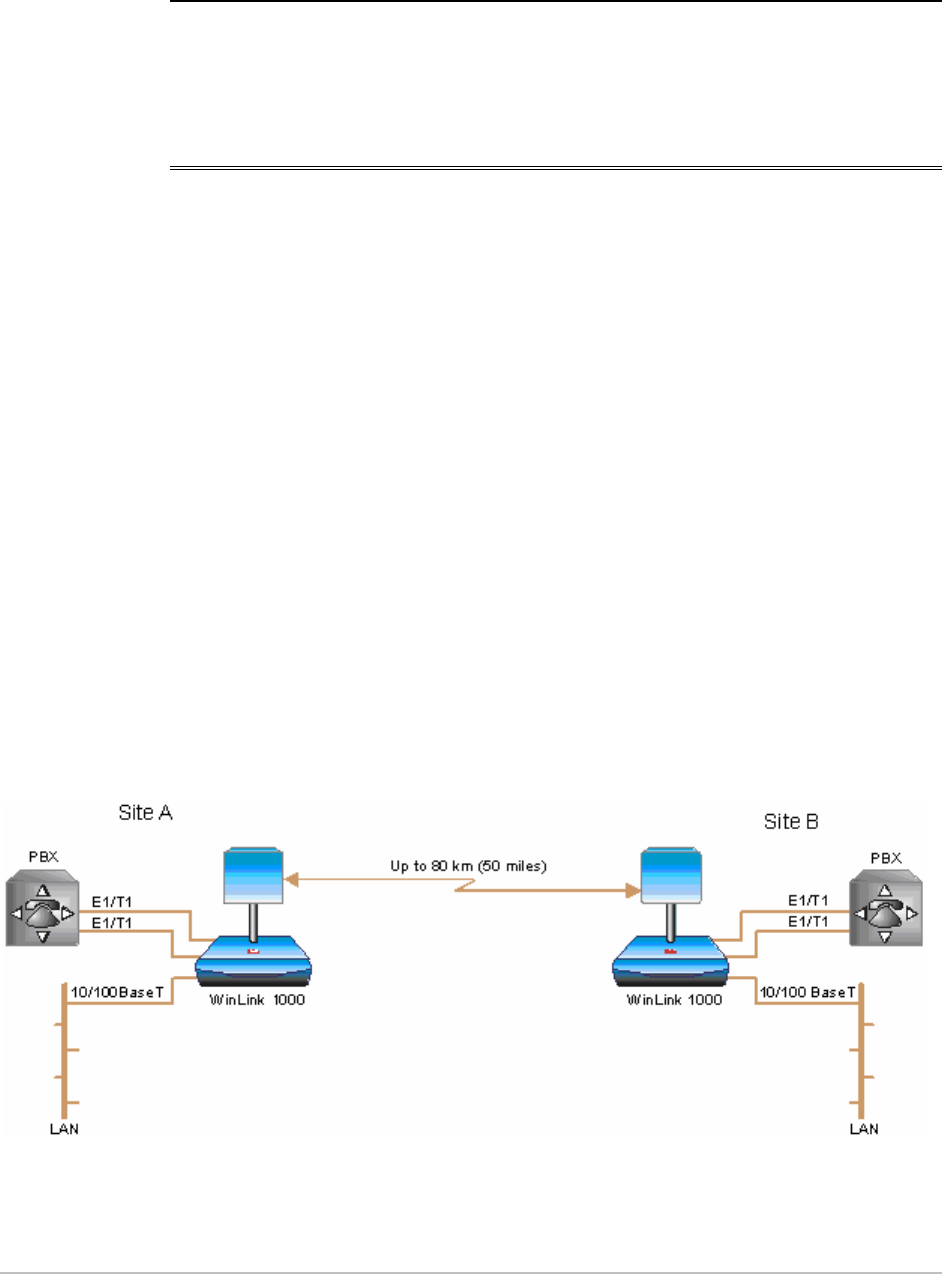
WinLink 1000 is a carrier-class, high capacity, Point-to-Point broadband
wireless transmission system. WinLink 1000 combines legacy TDM and
Ethernet services over 2.3, 2.4, 4.9 and 5.x GHz unlicensed bands, and
2.5 licensed band; and is suitable for deployment in FCC, ETSI, CN, UK,
and CSA-regulated countries. The system provides up to 48 Mbps
wireless link and supports ranges of up to 80 km (50 miles) with an
external antenna.
The screens shown in this manual are for version 1.700. For WinLink
1000 systems with earlier ODU hardware versions contact technical
support, support@radwin.com, for the relevant manual.
Application
Figure
1-1
illustrates a typical point-to-point application of two
WinLink 1000 units.
Figure
1-1. Typical Application
Overview 1-1

Chapter 1 Introduction WinLink 1000 Installation and Operation Manual
Versions
WinLink 1000 is available in several different frequency ranges, with
versions for ETSI and FCC regulations;
• F23, 2.300–2.400 GHz
• F24, 2.400–2.4835 GHz
• F25, 2.496–2.690 GHz
• F49, 4.940–4.990 GHz
• F53, 5.250–5.350 GHz
• F54, 5.470–5.725 GHz
• F58, 5.725–5.850 GHz
• F59, 5.865–5.935 GHz
Several special systems are also available;
• WL1000-AIND, All Indoor unit, F58/FCC with 4T1 support.
WL1000-AIND integrates the ODU and the IDU-C into a single 19"
IDU-C box.
• WL1000-ACCESS, Ethernet only units powered over the Ethernet via
PoE unit. Available in F23, F24, or F58 frequency ranges.
• WL1000-ACCESS-CL, ODU is equipped with special hardware for
the collocation of several units, using a method called Hub Site
Synchronization (HSS).
For the full product range see the latest WinLink 1000 brochure on our
website.
Features
Wireless Link
WinLink 1000 delivers up to 48 Mbps air rate for Ethernet and E1/T1
traffic. The system supports a variety of spectrum bands and can be
configured to operate in any channel in the band with a carrier step
resolution of 5, 10, or 20 MHz (2.x GHz versions support TDM at 10 or
20 MHz only).
WinLink 1000 operation complies with ETSI, CSA, CN, UK, and the FCC
47CFR Part 15 and subpart C and E requirements.
1-2 Overview

WinLink 1000 Installation and Operation Manual Chapter 1 Introduction
WinLink 1000 employs Time Division Duplex (TDD) transmission. This
technology simplifies the installation and configuration procedure.
There is no need to plan and to allocate separate channels for the
uplink and downlink data streams.
Operation over 2.4 GHz and 5.x GHz bands is not affected by harsh
weather conditions, such as fog, heavy rain etc.
LAN Interface
The WinLink 1000 LAN port provides 10/100BaseT interfaces with
autonegotiation and transparent VLAN support. Traffic handling is
provided by a MAC-level self-learning bridge.
TDM Interface
The WinLink 1000 TDM interface accepts E1 or T1 traffic, supporting
the following:
• Unframed operation (E1 and T1)
• AMI and B8ZS zero suppression (T1).
Advanced Encryption System
WinLink 1000 (version 1.500 and above) ensures user's data security
with one of the most sophisticated commercially available combined
encryption and authentication techniques, CCM/AES. This technique
combines message authentication (preventing antispoofing and replay
protection) with commercial encryption, and complies with the IEEE
802.11i (phase iii) security recommendations.
CCM/AES uses a symmetric 128-bit encryption key (EK), and a nonce,
and provides both message encryption and authenticating signature.
The nonce mechanism enables the receiver to remember already
received genuine messages and reject all replayed messages.
Initial encryption and authentication is based on a user-defined master
key (Link Password). While standard Wireless LAN encrypts only the
Ethernet Payload, WinLink 1000 encrypts both the source and
destination MAC addresses.
Management
WinLink 1000 has full local and remote management capabilities. The
user-friendly SNMP-based management tool provides full end-to-end
configuration, event log and performance monitoring capabilities.
Overview 1-3

Chapter 1 Introduction WinLink 1000 Installation and Operation Manual
Alternatively each site can be configured or monitored via a Telnet
terminal.
Diagnostics and Performance Monitoring
WinLink 1000 supports activating local and remote loopbacks on E1/T1
links.
WinLink 1000 constantly monitors the data transmission process,
evaluates received signal strength, and signal quality. It also monitors
received traffic and frame rate (FPS) for local and remote units.
Automatic Channel Select
Some versions of WinLink 1000 have the Automatic Channel Select
feature, which operates via a Dynamic Frequency Selection (DFS)
mechanism. This enables coexistence with any radar system that may
be active in the area. WinLink 1000 performs channel monitoring and
selects the channel with the lowest interference for the transmission.
WinLink 1000 operation complies with ETSI requirements where the
ETSI version has been purchased.
Adaptive Rate Modulation (ARA)
WinLink 1000 changes modulation automatically depending on channel
characteristics in order to guarantee continuation of service. The
adaptive modulation enables the user to maximize Ethernet
throughput without degradation of the TDM service quality. When
Ethernet only service is used, the adaptive modulation enables
improving the Ethernet performance in case of air performance
degradation (periodical interference or RSS changes).
In case of interference at one site, there is no need to use a lower
modulation at the other site (as in previous versions). In such a case
the actual rate changes automatically only at the problematic site,
while the second side of the link maintains the highest possible rate
(Asymmetric).
Adaptive modulation can be selected in both Installation and
Configuration wizards.
Transmit Power Control
The Transmit Power Control (TPC) function, provides the capability of
defining the transmit power in order to comply with the ETSI standard
1-4 Overview

WinLink 1000 Installation and Operation Manual Chapter 1 Introduction
requirement of
30 dB maximum. See
Table 4-1
for full details of transmit power
control.
Alarm Connector
The IDU-C has four external alarm inputs and outputs in the form of
dry-contact relays. The Alarm interface is located on the front panel of
the IDU-C and is a 9-pin D-type female connector. The user enables or
disables each of the alarms and configures the text that appears in the
alarm trap. The ODU sends the alarm within less than a second from
actual alarm trigger.
The alarm connector is available as an ordering option for the IDU-E.
Link Compatibility
WinLink 1000 indicates the version compatibility via software traps. As
new hardware is added to existing networks compatibility issues may
arise. Trap messages indicate the problem and suggest upgrades as
appropriate.
Optional External Antenna
WinLink 1000 supports configuration of an external antenna. In this
configuration, the outdoor unit is supplied with an N-type connector
that connects through a coax cable to the external antenna.
An external antenna can extend the range of the link, and in some
cases, may help to reduce environmental interferences. Various
external antennas are available for the WinLink 1000 operating
frequencies.
For example, an optional flat panel 28 dBi external antenna increases
the operation range of WinLink 1000 up to 80 km (50 miles).
Hub Site Synchronization
When several WinLink 1000 units are collocated at a common hub site
interference may occur from one unit to another. WinLink 1000 ODU
units are supplied with special hardware for the collocation of up to
eight units.
Using a method called Hub Site Synchronization (HSS) an external cable
is connected to all collocated WinLink 1000 ODUs, this cable carries
Overview 1-5
Chapter 1 Introduction WinLink 1000 Installation and Operation Manual
pulses sent to each ODU, which synchronize their transmission with
each other. (See
Appendix F
for more details).
E1 Trunk Redundancy
IDU-R units have a secondary E1 input which may be connected to
external equipment other than the ODU. This provides backup in the
event of failure of either the air interface link of the WinLink 1000, or
the secondary E1 link.
The user configures which of the two links is the main link and which is
the backup link.
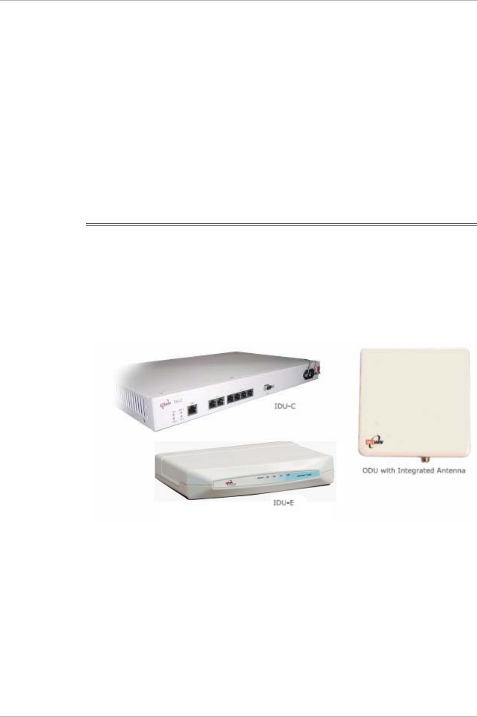
1.2 Physical Description
WinLink 1000 system consists of an Outdoor Unit (ODU) and an Indoor
Unit, which may be an IDU-E or an IDU-C.
Figure
1-2
shows the IDU-E, IDU-C carrier class unit, and an ODU with
integrated antenna.
Figure
1-2. WinLink 1000 Units
IDU-E
The front panel of the IDU-E includes five LEDs, which display the
status of E1/T1 traffic, wireless link, self-test results, the ODU-to-IDU
link, and power status. For a detailed description of the front panel
LEDs, see
Chapter 3
.
1-6 Physical Description

WinLink 1000 Installation and Operation Manual Chapter 1 Introduction
The rear panel of the IDU includes the connectors for power, WAN,
LAN, E1/T1, and the ODU. The wiring specifications are detailed in
Appendix A
. The rear panel LEDs are described in
Chapter 3
.
IDU-C
The IDU-C front panel includes four LEDs that display the status of
E1/T1and, wireless link, self-test results, and ODU-to-IDU link. For a
detailed description of the front panel LEDs, see
Chapter 3
.
ODU
ODU includes a power connector, which receives -48 VDC, and RJ-45
for Ethernet traffic from the IDU. The ODU is attached to a mast using a
special mounting kit, which is supplied with the unit.
The ODU can be used with an integrated antenna, as illustrated in
Figure
1-2
, or with an external antenna. If an external antenna is to be
used, then the ODU is supplied fitted with an N-type connector.
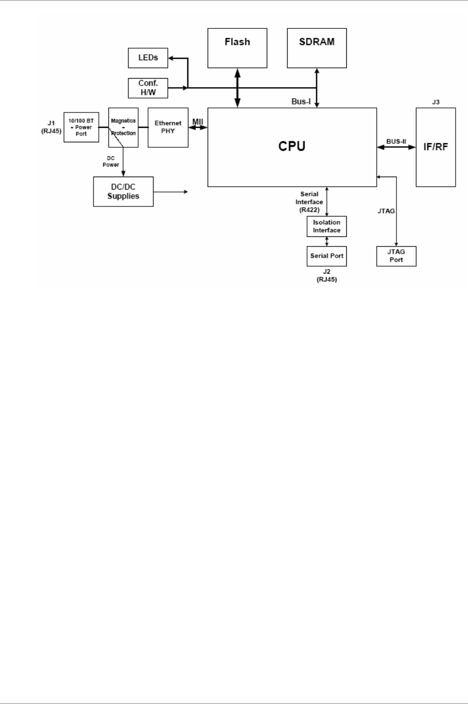
1.3 Functional Description
WinLink 1000 system comprises of the following units:
• Outdoor Unit (ODU): An enclosed aluminum frame with a front
sealed plastic cover, containing an integrated transceiver with an
antenna, RF module, modem and standard interfaces. The ODU
stores all the configuration parameters of the WinLink 1000 system.
Figure
1-3
shows the ODU block diagram.
• Indoor Unit (IDU-E or IDU-C): The interface unit between the ODU
and the user. It converts 100–240 VAC to -48VDC, and sends it on
to the ODU. The IDU does not store any configuration data.
Therefore, there is no need for additional configuration of the
WinLink 1000 system when replacing an IDU.
Functional Description 1-7
Chapter 1 Introduction WinLink 1000 Installation and Operation Manual
Figure
1-3. ODU Block Diagram
1-8 Functional Description

WinLink 1000 Installation and Operation Manual Chapter 1 Introduction
1.4 Technical Specifications
Air Interface
Technology
OFDM
Duplexing Method
Time Division Duplex (TDD)
Capacity
Configurable up to 48 Mbps
Modulation
OFDM - BPSK, QPSK, 16QAM, 64QAM
Channel Resolution
5/10/20 MHz (BRS systems 5 and 10 MHz
only)
Transmitter Power
Specification is different per product, for
further details refer to the
Link Budget
Calculator
Range
Up to 41 km (25.5 miles)
Up to 80 km (50 miles) with an external
antenna
ACCESS versions up to 20 km.
Frequency Bands
[GHz]
and Standards
2.300–2.483
2.496–2.690
4.940–4.990
5.150–5.350
5.470–5.725
5.725–5.850
FCC, ETSI
FCC part 27 (BRS)
FCC
FCC
ETSI
FCC
Antennas (See Antenna Characteristics in
Appendix E
)
LAN Interface
PHY
Up to 2 × 10/100BaseT, auto-sensing
Framing/Coding
IEEE 802.3/U
Bridging
Self-learning, up to 2048 MAC addresses
Line Impedance
100Ω
VLAN Support
Transparent
Frame Size
1536 bytes max
Connector
RJ-45
E1 Interface
Data Rate
Unframed (transparent) 2.048 MHz
(Specification may be different per ordering
Technical Specifications 1-9

Chapter 1 Introduction WinLink 1000 Installation and Operation Manual
option)
Line Interface
HDB3
Connector
RJ-45
No. of Ports
IDU-E: 1 or 2
IDU-C: 4
T1 Interface
Data Rate
Unframed (transparent) 1.544 MHz
(Specification may be different per ordering
option)
Zero Suppression
AMI, B8ZS
Connector
RJ-45
No. Of Ports
IDU-E: 1 or 2
IDU-C: 4
Indicators
PWR (green)
Power status (IDU-E only)
IDU (green)
IDU-C status
ODU (green/red)
ODU-to-IDU link status
LINK (green/red)
Link status
SERVICE (green/red)
E1/T1 signal status
Power
Source
IDU-E: 100–240 VAC via external AC/DC
converter
IDU-C: 100–240 VAC via AC cable
-48 VDC (-42 to –60 VDC)
24 VDC
Power Received by
the ODU
-48 VDC
Power Con umptions
ODU plus IDU-E – 10W max
ODU plus IDU-C – 14W max
Connector
IDU-E 2-pin
IDU-C AC – 3-pin IEC connector
DC – 3-pin terminal block
Connector
DB-9 female
Alarm
Connector
Electrical
Characteristics
Dry Contact, 30V/2A
Max input current, 0.01A at 0.5W (R=5K)
1-10 Technical Specifications

WinLink 1000 Installation and Operation Manual Chapter 1 Introduction
Physical
Outdoor Uni (ODU) t
r
t
r
With integrated
antenna
Height
24.5 cm / 9.3 in 30.5 cm / 12 in
Width
13.5 cm / 5.13 in 30.5 cm / 12 in
Depth
4.0 cm / 1.57 in 5.8 cm / 2.3 in
Weight
1.0 kg / 2.2 lb 1.5 kg / 3.3 lb
Indoo Unit
IDU-E IDU-C
Height
4.5 cm (1.7 in) 1U 4.5 cm (1.7 in) 1U
Width
23.5 cm (9.3 in) 29 cm (11.5 in)
Depth
16.5 cm (6.7 in) 43 cm (17.7 in)
Weight
0.5 kg (1.1 lb) 1.5 kg (3.3 lb)
Environment
Outdoor Uni (ODU)
Enclosure
All-weather case
Temperature
-35 to 60°C/-31 to 140°F
Indoo Unit (IDU-E and IDU-C)
Temperature
-0 to 50°C/32 to 122°F
Humidity
Up to 90%, non-condensing
Technical Specifications 1-11

Chapter 2
Installation and Setup
2.1 Introduction
This section describes the installation, alignment, and setup
procedures for a WinLink 1000 system.
After installing the hardware and establishing a link, refer to
Chapter 3
for operation instructions and
Chapter 4
for configuration instructions.
In case a problem is encountered, refer to
Chapter 5
for test and
diagnostic instructions.
•
Warning
Internal settings, adjustment, maintenance, and repairs may be
performed only by a skilled technician who is aware of the hazards
involved.
Always observe standard safety precautions during installation,
operation, and maintenance of this product.
2.2 Site Requirements and Prerequisites
For the IDU units, allow at least 90 cm (36 in) of frontal clearance for
operating and maintenance accessibility. Allow at least 10 cm (4 in)
clearance at the rear of the unit for signal lines and interface cables.
The ambient operating temperature should be –45 to 60°C/–49 to
140°F (ODU), or –5 to 45°C/23 to 113°F (IDU) at a relative humidity of
up to 90%, non-condensing.
2.3 Package Contents
The WinLink 1000 packages include the following items:
• ODU package contains:
Package Contents 2-1

Chapter 2 Installation and Setup WinLink 1000 Installation and Operation Manual
ODU
Mast/Wall mounting kit plus mounting instructions
WinLink 1000 Manager installation CD
Spare RJ-45 connector
• IDU-E package contains:
IDU-E
110V/220V adapter
IDU wall-mounting drilling template
Self adhesive label showing the IDU LED operation
Spare RJ-45 connector
Or
• IDU-C Package Contains:
IDU-C
Self adhesive label showing the MAC address and the alternative
community string KEY. Keep this label safe.
For AC model, 110/240 VAC with 3-pin terminal block connector
(green)
For DC model, 3-prong connector cable
Standard 1-U, 19” carrier rack
Spare RJ-45 connector
• External antenna (if ordered)
• ODU/IDU cable at length ordered (optional)
• Technical documentation CD
2.4 Equipment Required
The following is a list of the equipment required for installing the
WinLink 1000 hardware.
• RJ-45 crimp tool (if pre-assembled ODU/IDU cable is not used)
• Drill (for wall mounting only)
• IDU and ODU grounding cable
• 13 mm (½″) spanner/wrench
• ODU to IDU cable if not ordered (Outdoor class, CAT-5e, 4 twisted
pairs)
2-2 Equipment Required

WinLink 1000 Installation and Operation Manual Chapter 2 Installation and Setup
• Cable ties
• Laptop running Windows 2000 or Windows XP.
2.5 Installation Sequence
The WinLink 1000 system installation is achieved by following the
steps listed below:
1. Installing ODUs at both sites of the link.
2. Assembling the ODU cable and connecting ODU to IDU at both
sites.
3. Connecting the power.
4. Installing the management program on the network management
station.
5. Aligning the ODUs.
6. Use the Link Budget Calculator Application
7. Running the Installation wizard from the management program.
8. Connecting user equipment to the local and remote IDUs.
Figure
2-1
illustrates a typical installation of WinLink 1000 with an
external antenna.
Installation Sequence 2-3

Chapter 2 Installation and Setup WinLink 1000 Installation and Operation Manual
Figure
2-1. Typical Installation Diagram
2.6 Mounting the ODU
The ODU is the transmitting and receiving element of the WinLink 1000
system. The ODU can be mounted on a mast or a wall. In both
installations, the supplied mounting kit is used to secure the ODU.
Appendix B
describes the mast/wall installation instructions.
A WinLink 1000 link operates in pairs of two WinLink 1000 systems
with the same configuration. Both systems must be installed, and the
antennas of the outdoor units must be aligned for maximum
throughput.
2-4 Mounting the ODU

WinLink 1000 Installation and Operation Manual Chapter 2 Installation and Setup
•
Prior to connecting cables to the ODU, the protective earth terminal
(screw) of the ODU must be connected to an external protective ground
conductor or to a grounded mast.
Only a qualified person using the proper safety equipment should
climb the antenna mast. Only trained professional installers should be
used when installing or dismantling ODUs and masts.
Warning
Æ To mount the ODU:
1. Verify that the ODU mounting brackets are properly grounded.
2. Assemble the ODU unit onto the mast or wall. Refer to
Appendix B
for the ODU mounting instructions.
3. Connect the ground cable to the chassis point on the ODU.
4. Attach the ODU cable to the RJ-45 connector. Refer to
Appendix A
for the connector pinout.
5. Secure the cables to the mast or brackets using UV-rated cable ties.
6. Repeat the procedure at the remote site.
•
Note
Do not tightly secure the ODU to its mounting brackets until the
alignment process of the antenna is complete.
When installing the ODU, check that there are no direc obstructions in
front of the ODU or interference from man-made obs acles.
t
t
2.7 Connecting the ODU to the IDU
The ODU cable conducts all the user traffic between the IDU and the
ODU. The ODU cable also provides -48 VDC supply to the ODU. The
maximum length for one leg of the ODU cable is 100m (328 ft) in
accordance with 10/100BaseT standards.
ODU cable is supplied pre-assembled with RJ-45 connectors, at the
length specified when ordering. If the ODU cable was not ordered, use
Cat. 5e shielded cable. Wiring specifications are given in
Appendix A
.
Æ To connect the ODU to the IDU
1. Route the cable from the ODU location into the building.
2. Secure the cable along its path.
Connecting the ODU to the IDU 2-5
Chapter 2 Installation and Setup WinLink 1000 Installation and Operation Manual
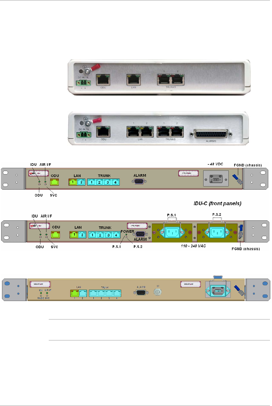
3. Connect the ODU cable to the RJ-45 connector on the IDU
designated ODU or WAN. The figures below illustrate typical IDU
panels. You may have differences in your panels depending on the
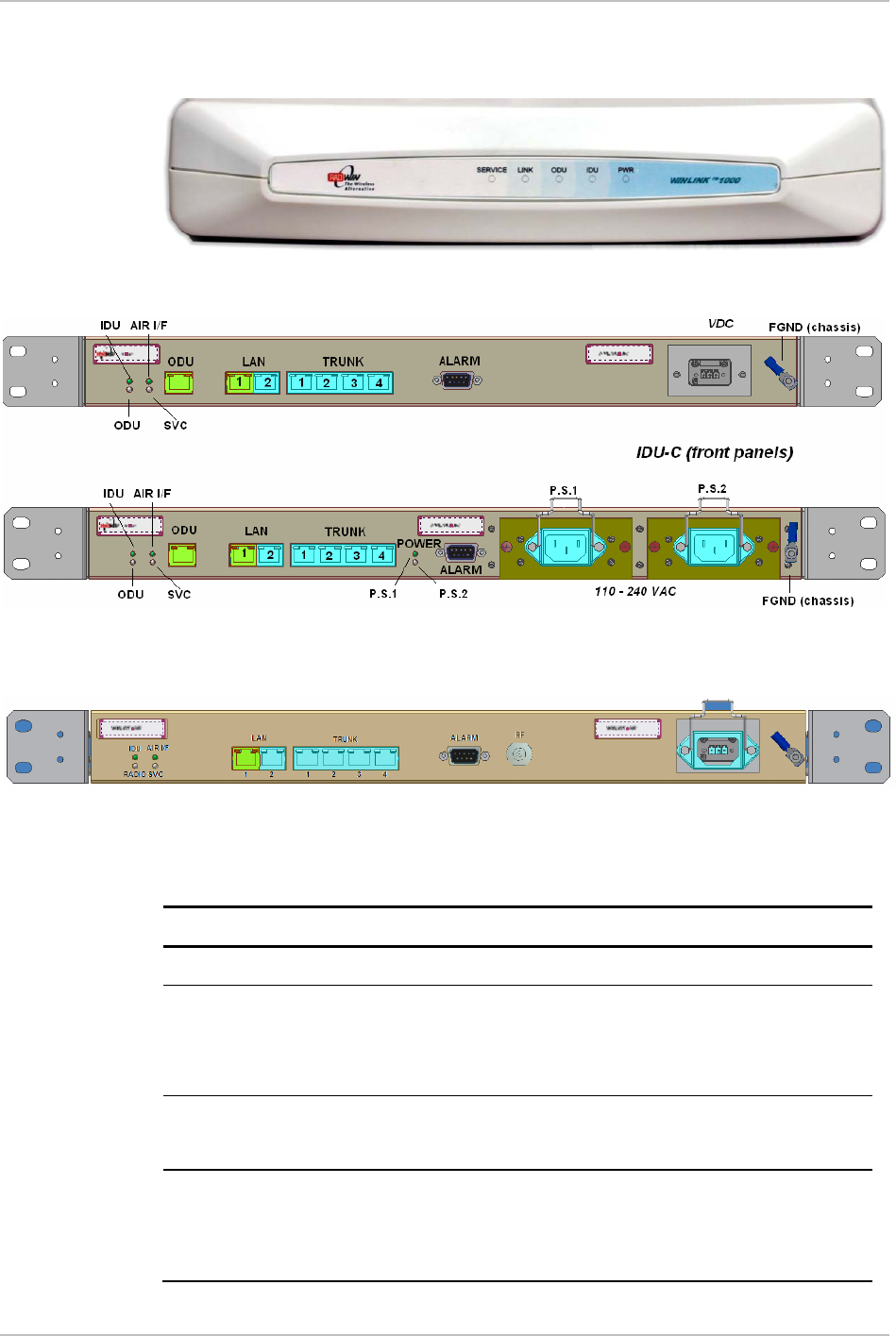
hardware ordered.
Figure
2-2. Typical IDU-E Rear Panel
Figure
2-3. IDU-2E1-AL Rear Panel
Figure
2-4. Typical IDU-C Front Panels
Figure
2-5. WinLink 1000-AIND All Indoor Radio Unit
•
The panels may be fitted with different connector combinations than
shown, depending on the model ordered.
Note
2-6 Connecting the ODU to the IDU

WinLink 1000 Installation and Operation Manual Chapter 2 Installation and Setup
2.8 Installing WinLink 1000 Management Software
The WinLink 1000 management application is distributed on CD-ROM as
an executable file. The application has the following PC requirements:
• Memory: 128 MB RAM
• Disk: 1 GB free hard disk space
• Processor: Pentium 3 or higher
• Network: 10/100BaseT NIC
• Graphics: Card and monitor that support 1024×768 screen
resolution
with 16 bit color
• Operating system: Windows 2000/XP
• Microsoft Explorer 5.01 or later.
Æ To install the WinLink 1000 management program:
1. Insert the CD-ROM into your CD-ROM drive.
2. The autorun feature starts to install the software automatically.
If the installation does not start automatically, run setup.exe.
3. Follow the on-screen instructions of the installation wizard to
complete setup of the WinLink 1000 Management program in the
desired location.
Any PC running the WinLink 1000 management application can be used
to configure WinLink 1000 units.
2.9 Connecting the Power
•
Before connecting any cable, the protective earth terminals of the
AC/DC adapter must be connected to the protective ground conductor
of the mains power cord. If you are using an extension cord (power
cable) make sure it is grounded as well.
Any interruption of the protective (grounding) conductor (inside or
outside the instrument) or disconnecting of the protective earth
terminal can make this unit dangerous. Intentional interruption is
prohibited.
Warning
Connecting the Power 2-7

Chapter 2 Installation and Setup WinLink 1000 Installation and Operation Manual
Connecting Power to an IDU-E
Power is supplied to the WinLink 1000 IDU-E via an external AC/DC
converter, which receives power from a 100–240 VAC source and
converts it to -48 VDC.
Æ To connect power to the IDU-E:
1. At site A, connect the 2-pin connector of the AC/DC converter to
the 2-pin DC power connector on the IDU-E rear panel.
2. Connect the AC/DC converter 3-prong plug to a mains outlet.
The unit turns on automatically upon connection to the mains.
The green PWR indicator turns on, and the IDU indicator blinks
orange for approximately 40 seconds during startup. See
Normal Indicators
section in Chapter 3.
After approximately 20 seconds the ODU starts beeping. The
beeps continue until the ODUs are aligned and the link set up.
3. Wait for approximately one minute, then repeat for Site B.
Connecting Power to an IDU-C
AC power is supplied to the WinLink 1000 IDU-C through a standard
3-prong plug.
AC power should be supplied via a 1.5m (5 ft) standard power cable
terminated by a standard 3-prong socket. A cable is provided with the
unit.
Æ To connect AC power to an IDU-C:
1. Connect the power cable socket to the power connector on the
WinLink 1000 front panel.
2. Connect the power cable plug to the mains outlet.
The unit turns on automatically upon connection to the mains.
Æ To connect DC power to an IDU-C
A special IEC 60320 adapter for-48 VDC power connection is supplied
with the unit.
2-8 Connecting the Power
WinLink 1000 Installation and Operation Manual Chapter 2 Installation and Setup
2.10 Starting the WinLink 1000 Manager Software
Æ To start the WinLink 1000 Manager:
1. Connect the management station to the LAN.
2. Double-click the WinLink 1000 Manager icon on the desktop, or
click Start > Programs > WinLink 1000 Manager.
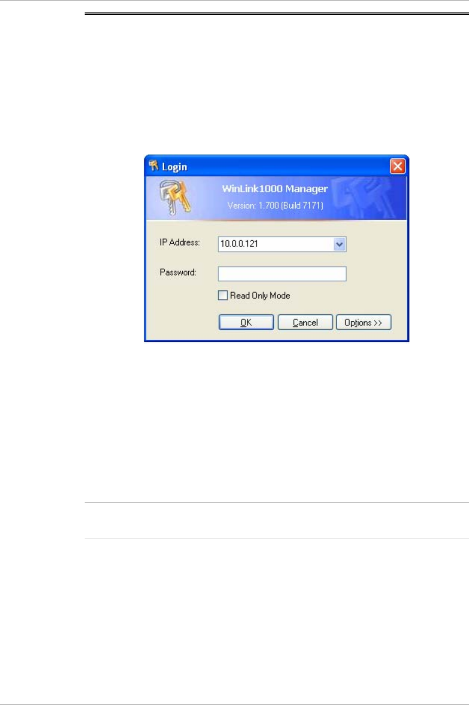
The Login dialog box appears.
Figure
2-6. Login Screen
3. Select the suitable option:
Select Local Connection (Broadcast), if user is connected directly
to the IDU LAN port.
Enter IP address (of the ODU)
Default address: 10.0.0.120
The Subnet mask is 255.255.255.0. Versions 1.700 and up, any
valid subnet mask may be used.
•
Note
The actual IP address i defined during link configuration (see sDefining
the Management Addresses).
4. Enter the password
Default password –
admin
(see the section on
Changing the
Management Password
)
5. Click the Read only check box if entering the system as a Read only
user.
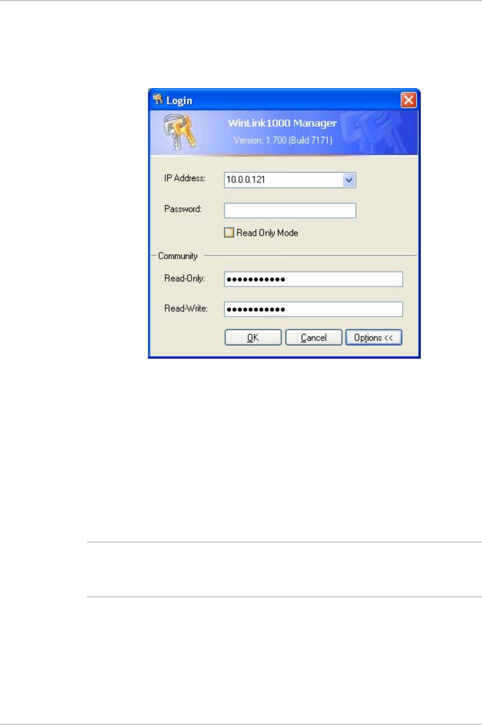
6. If you are a user with Read-Write permission, click Options to enter
the community options.
Starting the WinLink 1000 Manager Software 2-9
Chapter 2 Installation and Setup WinLink 1000 Installation and Operation Manual
WinLink 1000 is protected with Community passwords. A user may
be defined with read-only permission or with read-write
permission. See the section
Changing Community
Values
for more
detail.
Figure
2-7. Login Screen with Community Options Visible
• If using the system for the first time, enter netman (default) in the
read-only and read-write fields.
• If community values have previously been defined, enter them in
the read-only or read-write communities.
• If you are a user with read-only permission, click the Read Only
Mode check box.
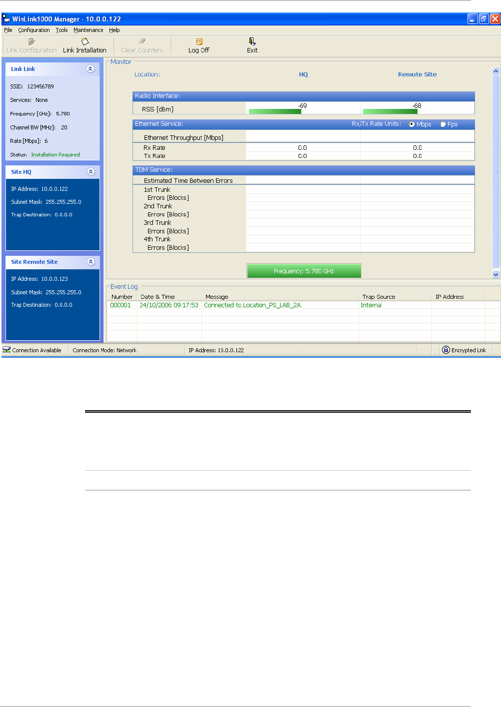
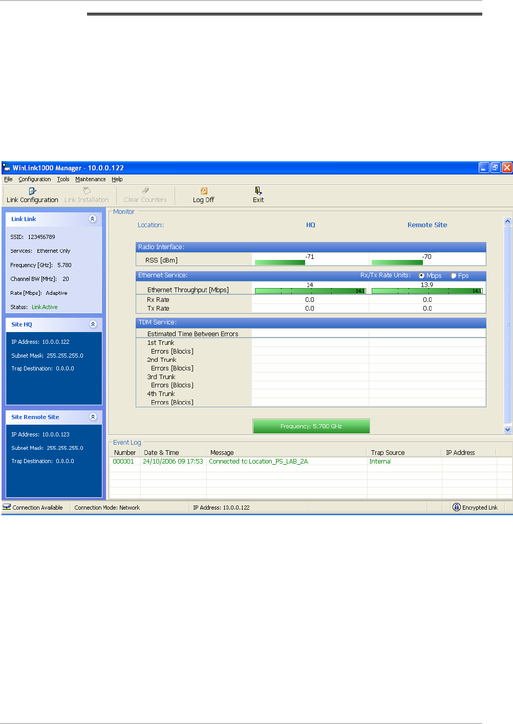
The WinLink 1000 Manager main screen is displayed (see
Figure
2-8
).
Not
e
With BRS systems the link must be activated at both sites when
installing for the first time. A red Inactive Link box appears in the
center of the Manager screen. Activation is performed later.
2-10 Starting the WinLink 1000 Manager Software
WinLink 1000 Installation and Operation Manual Chapter 2 Installation and Setup
Figure
2-8. WinLink 1000 Manager Main Screen
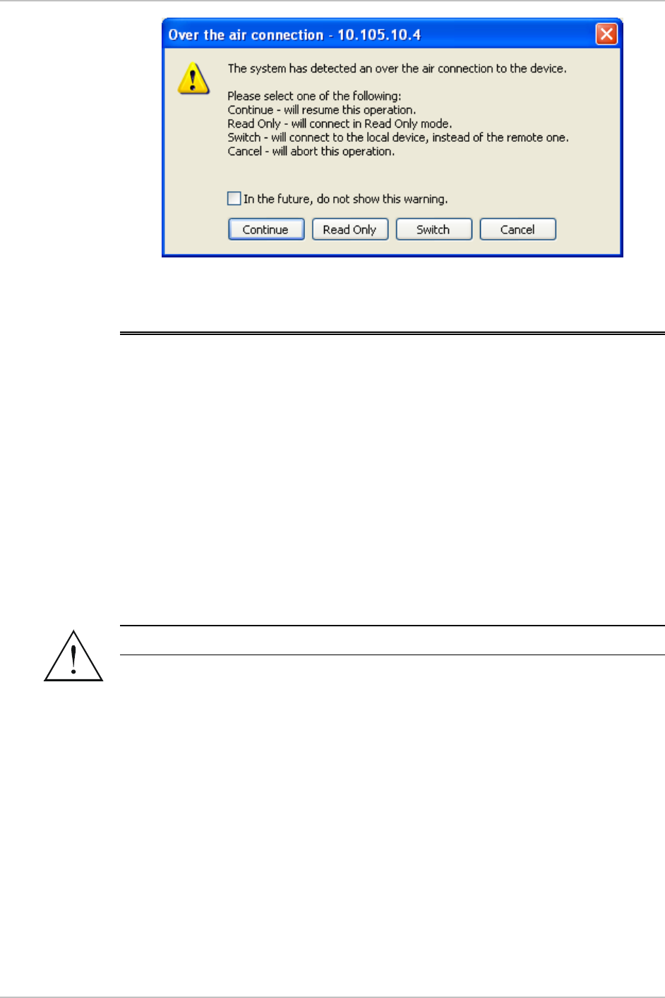
2.11 Over the Air Connection indication
During the login the Manager reports on over the air connection.
Note
Over the Air connection to remote unit is not recommended
• Select the relevant option for your login requirements.
Over the Air Connection indication 2-11
Chapter 2 Installation and Setup WinLink 1000 Installation and Operation Manual
Figure
2-9. Over the Air Connection
2.12 Aligning ODUs with the Beeper
Perform the WinLink 1000 ODU alignment using the beepers located
inside the ODUs. The beeper facility is not suitable for aligning the All
Indoor Units, AIND. To align an AIND system see
Appendix D
for
alternative alignment methods.
To speed up the installation time, alignment of a WinLink 1000 Link
can be performed by two teams simultaneously, at site A and at site B.
Æ To align the ODUs via ODU Beeper:
1. Verify that power is connected to the IDUs at both sites.
•
Warning
Do not stand in front of a live ODU.
2. The ODU starts beeping 20 seconds after power up, and continues
beeping until the ODUs are aligned, and the link is established.
3. Verify normal operation of the IDU by the LED indications on the
front panel. (See
Normal Indications
.)
4. Coarsely align the site B ODU in the direction of the site A ODU.
5. Make an azimuth sweep of 180 degrees with the site A ODU. So
that the strongest signal from site B can be learnt.
6. Slowly turning the site A ODU back towards the position of Site B,
listen to the beeps until the best signal is reached. See
Figure
2-10
for the beeper signals.
2-12 Aligning ODUs with the Beeper

WinLink 1000 Installation and Operation Manual Chapter 2 Installation and Setup
Beeper Sequence
=beeper on
=beeper off
Description
[approx. 1s]
Best Signal so far
Signal quality increased
No change in signal
Signal quality decreased
[approx. 2s]
No air link
Figure
2-10. Beeper Sequence for ODU Alignment
Note
•
Three beeps and a pause is the best signal
Two beeps and a pause, signal quality increased
One beep and pause is no signal change
Any other signal detects no signal between ODUs.
7. Secure the site A ODU to the mast/wall.
8. At site B, adjust the ODU slowly whilst listening to the beeper
sequence until the best signal is attained.
9. Secure the site B ODU to the mast/wall.
10. Monitor the link quality for about 15 minutes to verify stability.
2.13 Calculating the Air Interface Rate
The Air Interface rate is the data transmission rate from one site to the
other, over the wireless WinLink 1000 interface. Use the
Link Budget
Calculator Utility
in order to calculate the optimal air interface rate and
the expected performance of the link operating at the user’s
requirements.
The ARA, Adaptive Rate Modulation feature performs this task
automatically and ensures that the transmission rate is set to
maximum whilst the link quality throughput is maintained.
Æ To open the Link Budget Calculator Utility
1. Click Help on the Menu Bar.
Calculating the Air Interface Rate 2-13

Chapter 2 Installation and Setup WinLink 1000 Installation and Operation Manual
2. Select Link Budget Calculator.
The Link Budget Calculator Utility opens. See
Appendix C
for full
instructions how to use the Link Budget Calculator Utility.
2.14 Installing the Link
During the installation procedure, the definition of all parameters is
automatically applied to both sides of the link.
For HSS screens specific to WinLink 1000-ACCESS-CL units see
Appendix F
.
Not
e
Æ To install the link:
1. Verify that the management station is properly connected to the
same LAN as the IDU, and the WinLink 1000 Manager application is
running.
2. With BRS systems you need to activate the link at both sites, see
Appendix G
for method. Once the link is activated, continue
installation from this point.
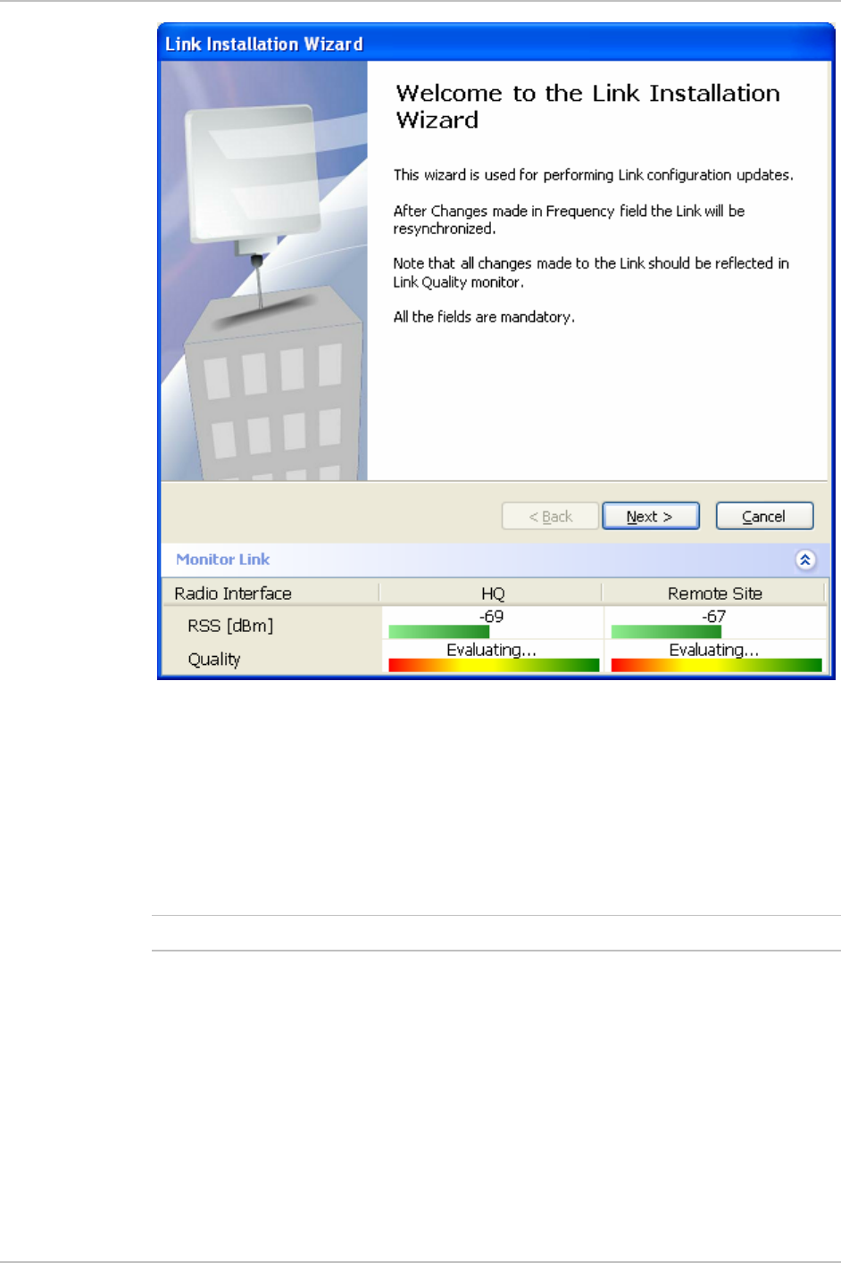
3. In the toolbar, click the Link Installation button.
The Installation wizard opens, (see
Figure
2-11
).
2-14 Installing the Link
WinLink 1000 Installation and Operation Manual Chapter 2 Installation and Setup
Figure
2-11. Link Installation Wizard
4. Click Next to proceed with the installation procedure.
A message box is displayed.
5. On the first installation the default link password must be changed.
Click OK in the message box.
The Change Link Password dialog box opens.
Note
Use the Hide Characters check box for maximum security.
Installing the Link 2-15

Chapter 2 Installation and Setup WinLink 1000 Installation and Operation Manual
Figure
2-12. Change Link Password dialog box
6. Enter the default link password wireless-bridge.
7. Enter a new password.
8. Retype the new password in the confirm field.
9. Click OK.
10. Click Yes when asked if you want to change the link password.
11. Click OK at the successful message.
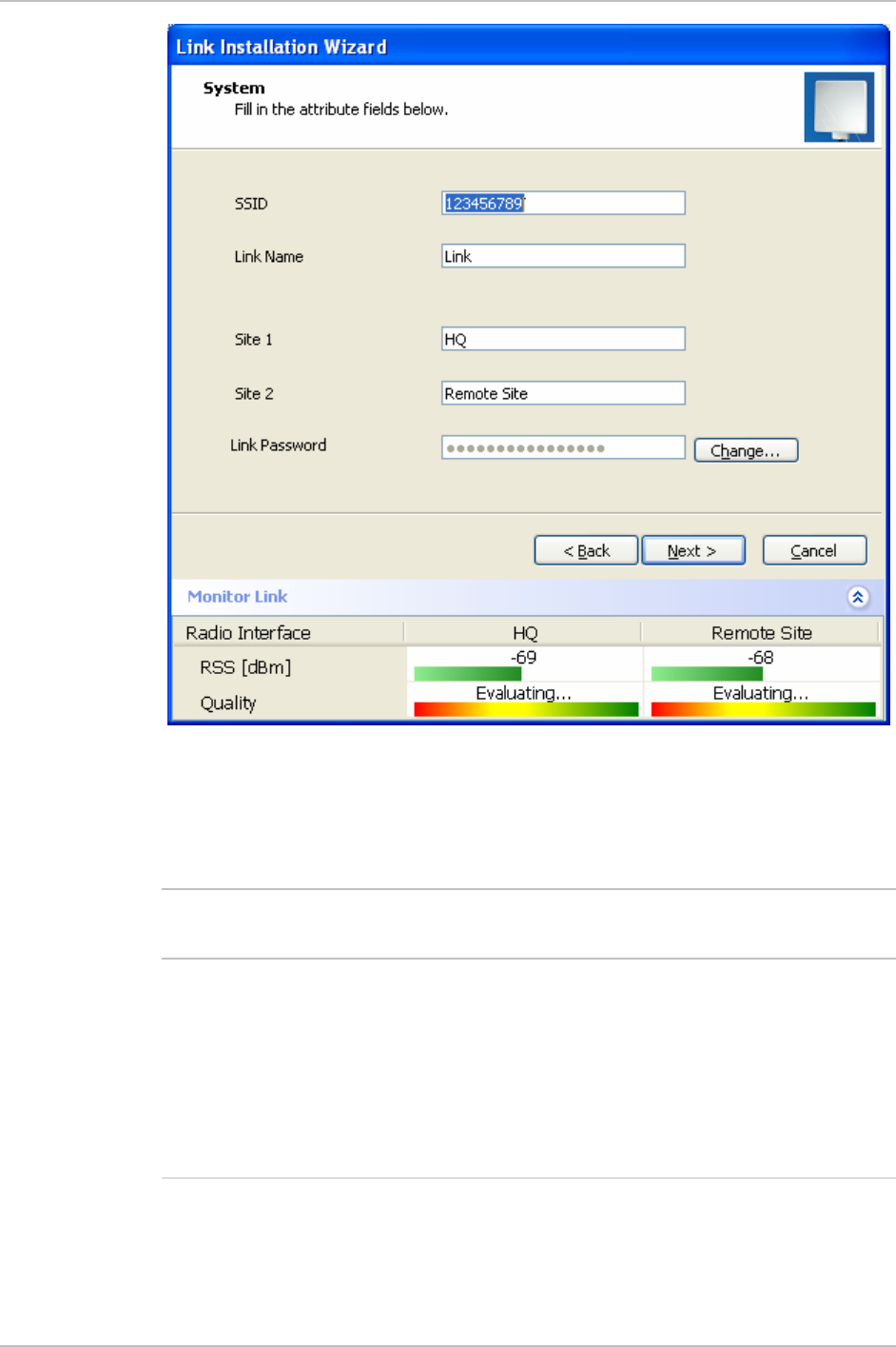
The system dialog box opens (see
Figure
2-13
)
2-16 Installing the Link
WinLink 1000 Installation and Operation Manual Chapter 2 Installation and Setup
Figure
2-13. Installation Wizard, System dialog box
12. Enter a SSID (System ID). The SSID must include at least eight
alphanumeric characters. Up to 24 characters are allowed.
•
Note
Both sides of a link must have the same SSID number for data
transmission to take place.
13. Enter a Link Name for the link identification.
14. Enter a name for site 1.
15. Enter a name for site 2.
16. Enter the Link Password (version 1.400 and after). See
Changing the
Link Password
for details on the Link Password.
•
No
te
It the Link Password is incorrect a link is established but configuration
cannot be performed and no services are available. A new link
password may be obtained from Technical Support or use the
Installing the Link 2-17

Chapter 2 Installation and Setup WinLink 1000 Installation and Operation Manual
alternative password supplied with the product.
See
Changing the Link
Password for more details.
17. Click Next.
The default link with a rate of 9 Mbps is evaluated.
The
Channel Setting
dialog box appears. This dialog box may be
different according to the version that you have purchased.
Selecting Channels
WinLink 1000 later than version 1.300 have a feature called Automatic
Channel Select, which allows you to define several alternative
frequency channels if interference is detected on the channel in use.
• For WinLink 1000 with the Automatic Channel Select feature see
WinLink 1000 with Automatic Channel
Select
(applies to versions
after 1.300).
• For WinLink 1000 5.4 GHz ETSI version see
WinLink 1000 5.4 GHz
ETSI
Version.
WinLink 1000 with Automatic Channel Select
Automatic Channel Select (ACS) gives WinLink 1000 the ability to
change frequency channels automatically if interference is detected on
the current operating channel.
2-18 Installing the Link
WinLink 1000 Installation and Operation Manual Chapter 2 Installation and Setup
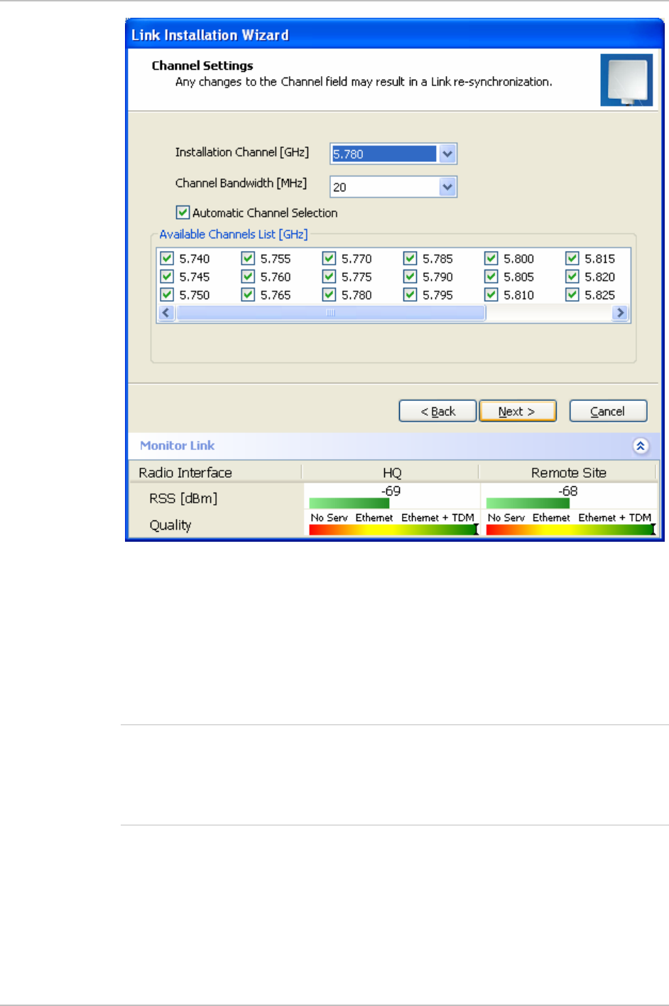
Figure
2-14. Channel Select dialog box - Automatic Channel Select
1. Select the main frequency from the Installation Channel menu.
2. Select the required Channel Bandwidth 5, 10, or 20 MHz. Default is
20 MHz.
When changing the channel bandwidth WinLink 1000 repeats
evaluation of the link.
Not
e
ACS is disabled if 5 or 10 MHz steps are selected.
F2.x GHz versions with TDM services operate at 10 or 20 MHz steps
only.
Ethernet Only also suppor s 5 MHz bandwidth. t
3. Click the check box if Automatic Channel Selection is required.
4. Click the check boxes in the Available Channels List of all the
allowable channels that can be automatically selected.
Installing the Link 2-19

Chapter 2 Installation and Setup WinLink 1000 Installation and Operation Manual
Selecting a new channel causes the system quality to change. The
quality bar shows the adjustment until the system finds the best
quality link.
5. If you are not satisfied with the channel that is selected
automatically, click Reselect Channel.
A new channel is selected from one of the Available Channels
that has been defined.
6. Click Next.
The Evaluating Rate box appears. When the optimum rate for the
link is selected the Service Parameters dialog box opens.
WinLink 1000 5.4 GHz ETSI Version
In accordance with ETSI, if WinLink 1000 detects Radar interference it
changes the frequency channel automatically. This feature is termed
Dynamic Frequency Selection (DFS). In this version, the Automatic
Channel Selection is selected by default and a minimum of two
channels must be defined as available.
1. Select the main frequency from the Operating Channel menu.
2. Select the Bandwidth required.
•
Note
Automatic Channel Selection is selected by default.
3. Click at least two check boxes in the Available Channels List of all
the allowable channels that can be automatically selected.
•
Note
Installation will not continue until at least two channels are defined.
Selecting a new channel causes the system quality to change. The
quality bar shows the adjustment until the system finds the best
quality link.
Any channel selected is evaluated for 60 seconds; therefore this
selection process may take a few minutes.
4. If you are not satisfied with the channel that is selected
automatically, click Reselect Channel.
A new channel will be selected from one of the Available
Channels that has been defined.
5. Click Next.
The Evaluating Rate box appears. The optimum rate for the link
is selected.
2-20 Installing the Link

WinLink 1000 Installation and Operation Manual Chapter 2 Installation and Setup
The Service Parameters dialog box opens.
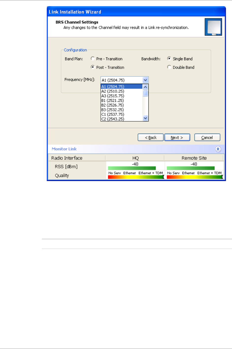
WinLink 1000 BRS Version
Both sites in a BRS Link must be configured identically.
Any changes to the frequency settings cause the link to re-
synchronize. A short loss of servi e will occur during re-
synchronization.
c
Not
e
Æ To Configure BRS Channel Settings
1. Set the Band Plan.
2. Select the Bandwidth required,
Single Band
Double Band
3. Select the Frequency from the pull-down menu.
4. Click Next. The system is re-synchronized to the changes.
Installing the Link 2-21
Chapter 2 Installation and Setup WinLink 1000 Installation and Operation Manual
Figure
2-15. BRS Channel Settings Post-Transition
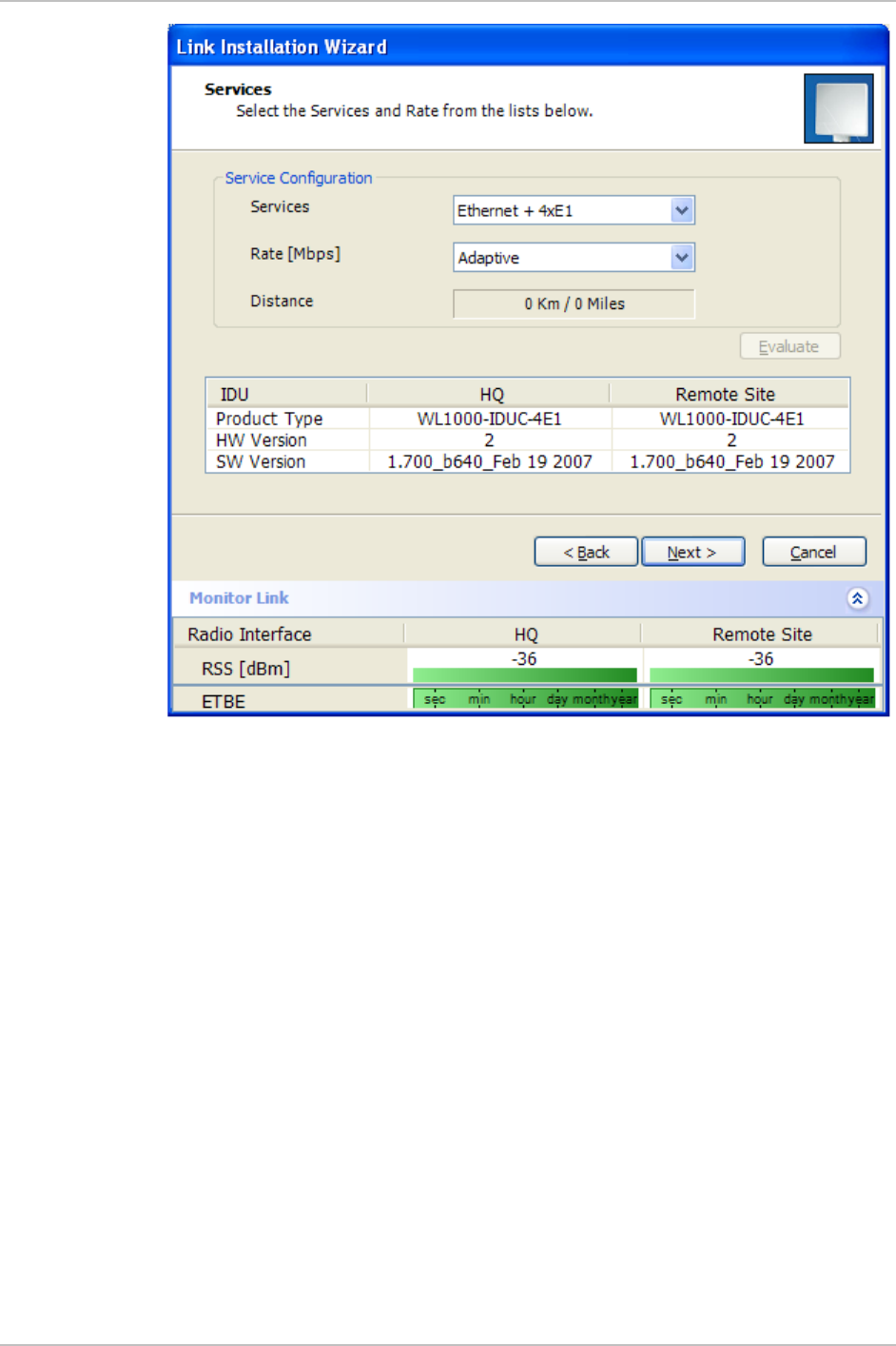
Selecting the Service Parameters
The user defines the type of service required, Ethernet Only or Ethernet
with TDM. The bandwidth remaining available for Ethernet if TDM
services are required is shown in the dialog box.
WinLink 1000 ACCESS versions are Ethernet Only.
Not
e
2-22 Installing the Link
WinLink 1000 Installation and Operation Manual Chapter 2 Installation and Setup
Figure
2-16. Installation Wizard, Services dialog box
Æ To select the services:
1. In the Service dialog box, select one of the following:
E1/T1 – E1/T1 data and Ethernet data.
The Ethernet BW field shows the remaining bandwidth in Mbps
available for Ethernet. The available bandwidth depends on the
number of E1/T1 ports selected.
Ethernet Only
2. Select the required transmission rate.
If Adaptive is selected WinLink 1000 constantly monitors and
adjusts the transmission rate to ensure maximum throughput for
the link at the highest quality. ACCESS versions are preset to
adaptive and the rate selection is disabled.
3. Click Next.
If TDM services were selected, then the TDM parameters dialog
box appears, (see
Figure
2-17
).
Installing the Link 2-23

Chapter 2 Installation and Setup WinLink 1000 Installation and Operation Manual
4. The optimum transmission rate for the selected services is
evaluated.
Table
2-1
shows the rates used by WinLink 1000.
ACCESS versions do not have TDM services, they operate at a default
rate of 2 Mbps.
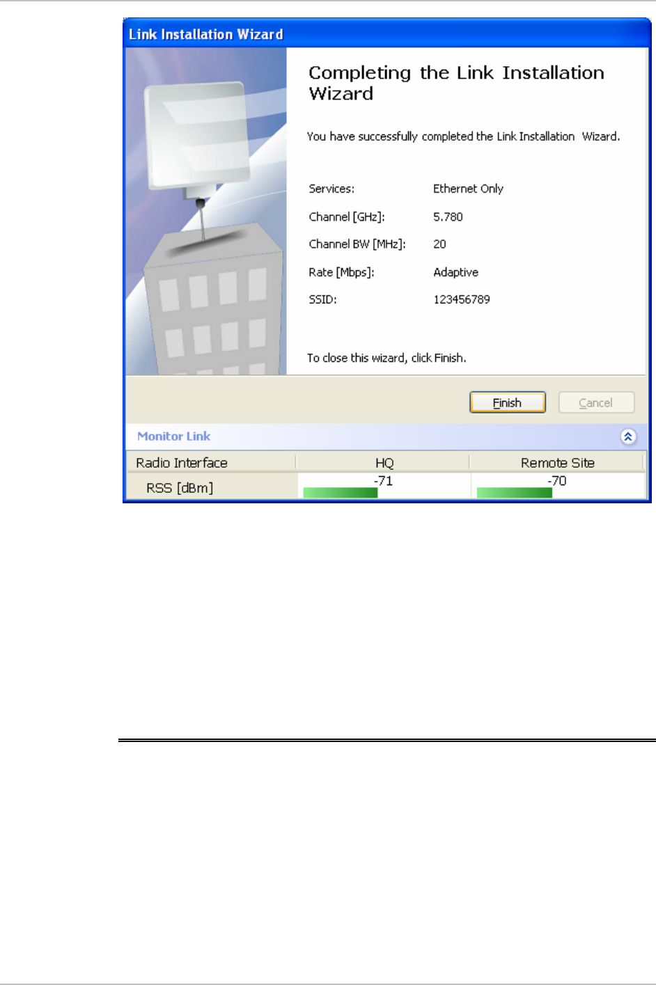
If Ethernet Only was selected, then the Finish screen appears
(see
Figure
2-19
) showing a summary of the link configuration,
the alignment is complete.
Table
2-1. Rates per Bandwidth
Modulation/FEC 5 MHz 10 MHz 20 MHz
BPSK / ¾ 2.25 Mbps 4.5 Mbps 9 Mbps
QPSK / ½ 3 Mbps 6 Mbps 12 Mbps
QPSK / ¾ 4.5 Mbps 9 Mbps 18 Mbps
16QAM / ½ 6 Mbps 12 Mbps 24 Mbps
16QAM / ¾ 9 Mbps 18 Mbps 36 Mbps
64QAM / 2/3 12 Mbps 24 Mbps 48 Mbps
64QAM / ¾ 13.5 Mbps 27 Mbps
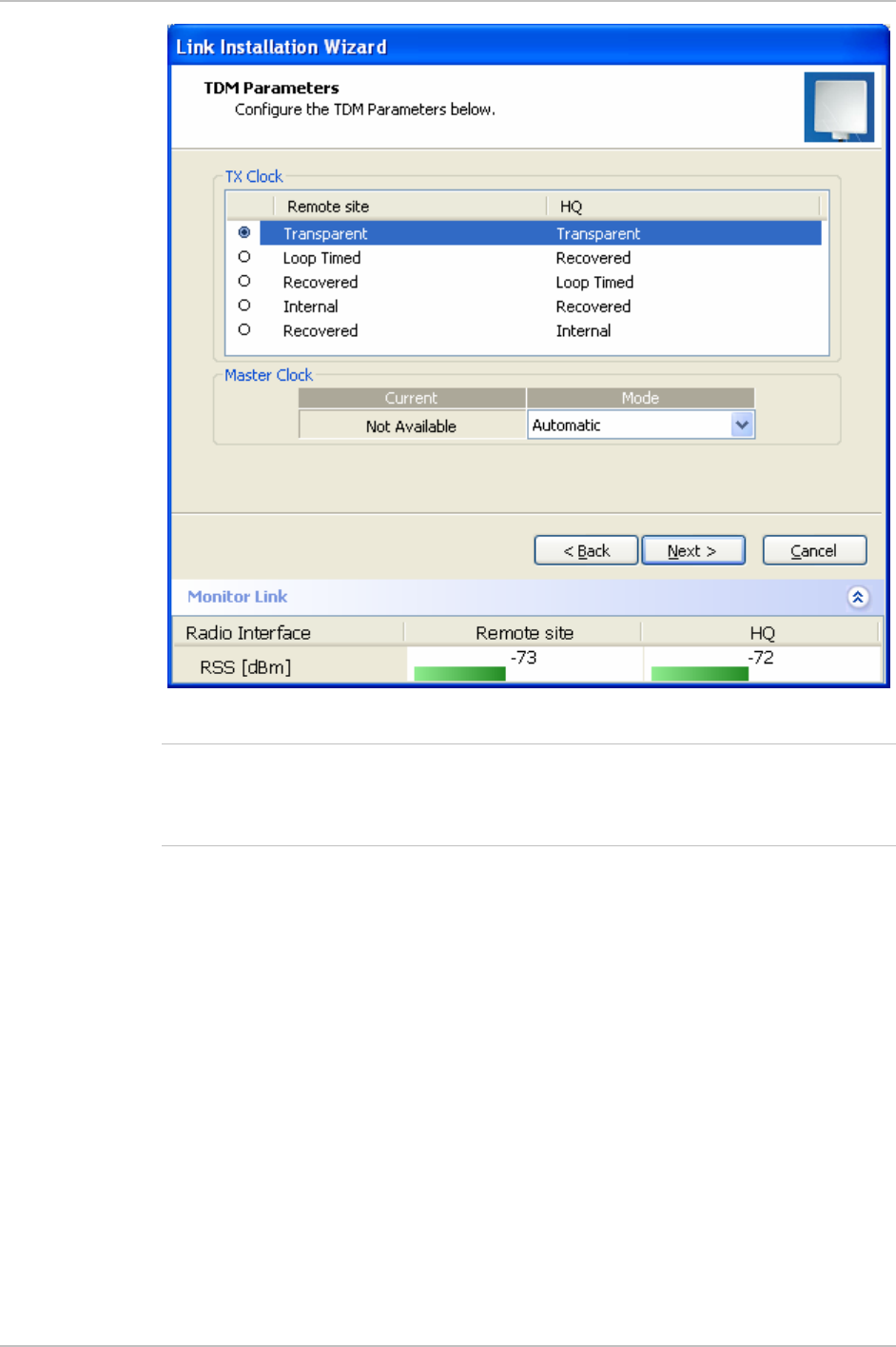
Setting the Clock Configuration
If TDM services are selected then the TDM parameters dialog box
appears. (TDM is not relevant in WinLink 1000 ACCESS versions.)
The TDM Parameters dialog box contains five working modes; select
the appropriate clock mode according to your application. Choosing
one of these modes sets the TDM clock behavior on both sides of the
link. The user equipment must be configured as described
Table
2-2
.
Table
2-2. TDM Clock Modes
Unit clock mode User equipment side
Local Unit Remote
Unit
HQ side Branch side
1 Transparent Transparent Internal/Recov
er
Internal/Recov
er
2 Loop Time Recover Internal Recover
3 Recover Loop Time Recover Internal
Not
e
2-24 Installing the Link

WinLink 1000 Installation and Operation Manual Chapter 2 Installation and Setup
Unit clock mode User equipment side
Local Unit Remote
Unit
HQ side Branch side
4 Internal Recover Recover Recover
5 Recover Internal Recover Recover
Transparent/Transparent
WinLink 1000 transparently regenerates the clock from line
clock side to Tx clock on the opposite side of the link.
Loop time/Recover
The local unit receive clock is the transmit clock on both sides
of the link.
Recover/Loop time
The remote unit receive clock is the transmit clock on both
sides.
Internal/Recover
The local unit internal oscillator generates the clock while the
remote unit recovers this clock.
Recover/Internal
The remote unit internal oscillator generates the clock while the
local unit recovers this clock.
•
Note
The Line code option is used with T1 Systems.
Installing the Link 2-25
Chapter 2 Installation and Setup WinLink 1000 Installation and Operation Manual
Figure
2-17. TDM Parameters dialog box
•
This dialog box is available only with IDU-E units, it is activated a ter
TDM service was chosen in the previous Service dialog box. In Ethernet
only services, the TDM dialog box does not appear.
f
Note
Setting the T1 Line Code
The T1 line code can be set as B8Zs or AMI in the TDM Parameters
dialog box.
The default is B8ZS.
Æ To change the line code
• In the TDM Parameters dialog box, set the line code to B8ZS or AMI.
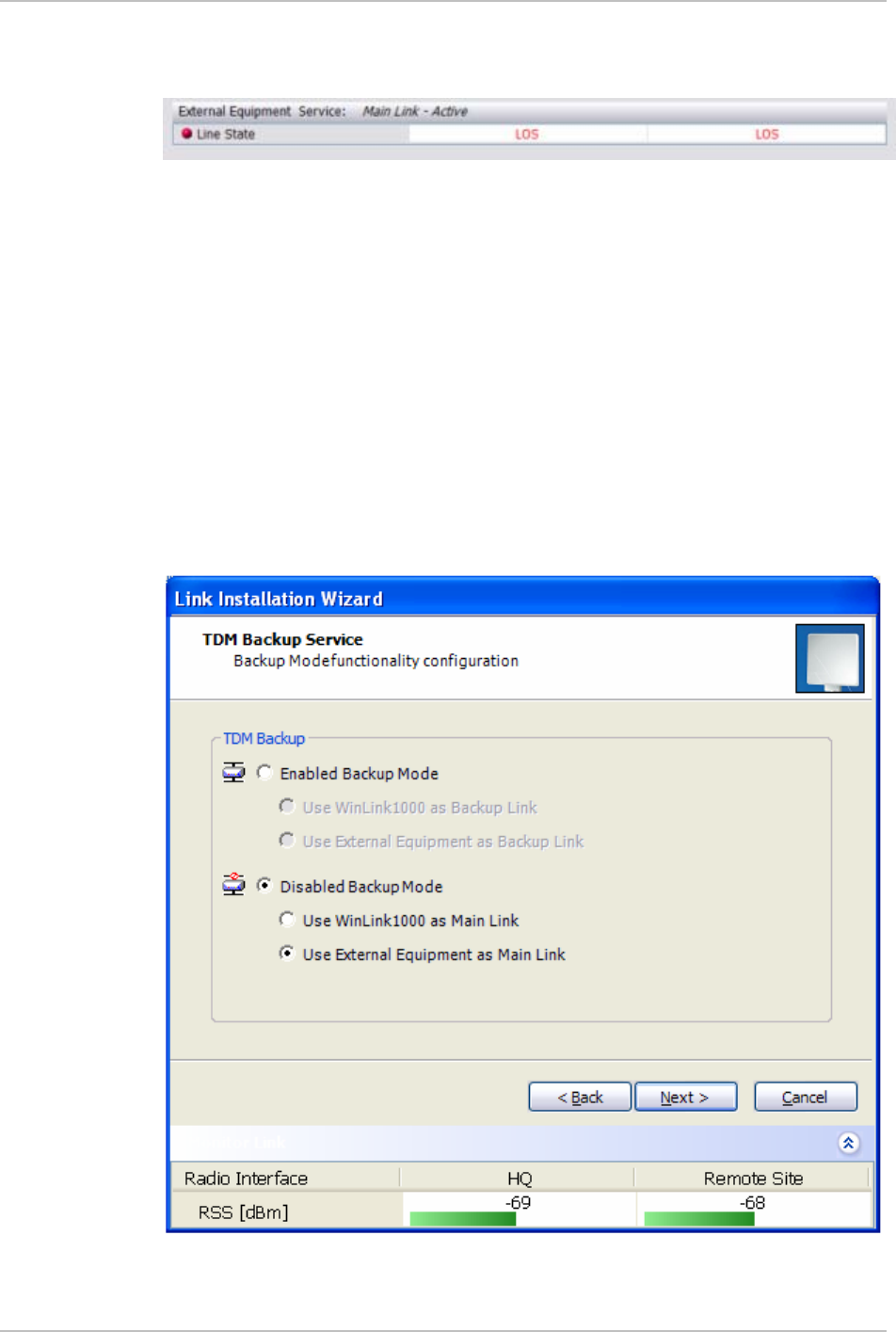
Setting the TDM Backup
IDU-R units have two E1 trunk lines, one for WinLink 1000 air interface
via the ODU, and the second external equipment such as a PBX. The
TDM backup screen is displayed in IDU-R systems only.
2-26 Installing the Link
WinLink 1000 Installation and Operation Manual Chapter 2 Installation and Setup
The external equipment status is displayed on the Main screen of the
Manager in IDU-R systems.
Æ To use the Backup Mode
1. Click Enabled Backup Mode.
2. Set which link is backup link; either WinLink 1000 or the external
equipment.
The second link becomes the main link.
Æ To disable the Backup mode
1. Click Disable Backup Link
2. Set which link is the Main Link; either WinLink 1000 or the external
equipment.
Figure
2-18
shows the TDM backup screen.
Figure
2-18. TDM Backup, IDU-R units only
Installing the Link 2-27
Chapter 2 Installation and Setup WinLink 1000 Installation and Operation Manual
Figure
2-19. Installation Wizard, Finish Screen
3. Click Finish to complete the installation wizard.
When the wireless link is established between the site A and site B
units, the Quality bar is within the yellow area for Ethernet only
links, or within the green area for Ethernet plus TDM links.
4. Verify that the Radio Signal Strength (RSS) is according to expected
results as determined by the Link Budget Calculator.
2.15 Connecting the User Equipment
The IDU is a standalone desktop, wall-mounted or rack-installed unit.
Figure
2-2
illustrates a typical rear panel of the IDU.
Æ To connect user equipment to the IDU:
1. Connect user E1/T1 traffic to the IDU panel RJ-45 port designated
TRUNK. There may be multiple Trunk ports available depending on
2-28 Connecting the User Equipment

WinLink 1000 Installation and Operation Manual Chapter 2 Installation and Setup
unit ordered.
Refer to
Appendix A
for the connector pinout.
2. Connect user hub/router or any other compatible device to the IDU
panel
RJ-45 port designated LAN. There may be multiple LAN ports
available for connecting to different LANs depending on the IDU
unit ordered.
Refer to
Appendix A
for the connector pinout.
•
Notes
Use a straight cable for rou er connection. t
Do not connect two LAN ports to the same LAN, or flooding may occur.
Connecting the User Equipment 2-29

Chapter 3
Operation
This section provides the following information for WinLink 1000:
• Operating procedures (turning-on and turning-off)
• IDU indicators
• Normal Indications
• Default settings
• Managing the WinLink 1000
3.1 Turning On WinLink 1000
Æ To turn on WinLink 1000:
• Connect the AC/DC converter to the IDU power connector and to
the mains. See
Chapter 2
for full instructions on connecting the
power.
The PWR indicator lights up (IDU-E only) and remains lit as long
as the IDU is receiving power.
WinLink 1000 requires no operator attention once installed, with the
exception of occasional monitoring of front panel indicators and
statistics data. Intervention is only required when WinLink 1000 must
be configured to its operational requirements, or diagnostic tests are
performed.
3.2 Controls and Indicators
IDU Front Panel Indicators
The front panel of the IDU and IDU-E includes a series of LED
indicators that show the operating status of the unit.
Figure
3-1
shows
Controls and Indicators 3-1
Chapter 3 Operation WinLink 1000 Installation and Operation Manual
the IDU-E front panel,
Figure
3-2
shows an IDU-C front panel.
Table
3-1, Table
3-2
,
and
Table
3-3
describe the indicators.
Figure
3-1. IDU-E Front Panel
Figure
3-2. Typical IDU-C Front Panels
Figure
3-3. WinLink 1000-AIND All Indoor Radio Unit
Table
3-1. Front Panel LEDs
Name Color Function
PWR Green ON –Power supply is ON (IDU-E only)
IDU Green
Orange
Red
ON – IDU operational
ON – During power-up only
ON – Failure
ODU Green
Red
ON – ODU-to-IDU communication link is operating
ON – ODU-to-IDU communication link is disrupted
LINK Green
Orange
Red
ON – Wireless link is synchronized
ON – During installation only
ON – Wireless link lost synchronization
3-2 Controls and Indicators

WinLink 1000 Installation and Operation Manual Chapter 3 Operation
SERVICE Green
Orange
Red
ON – E1 or T1 line is synchronized
ON – Alarm detected at the remote interface
ON – Local or Remote loopback
ON – Alarm detected at the local interface
WAN/LAN Indicators
The WAN/LAN and TDM connectors (IDU-E rear panel, IDU-C front
panel) have LED indicators that show the operating status.
Table
3-2
and
Table
3-3
describe the indicators.
Controls and Indicators 3-3

Chapter 3 Operation WinLink 1000 Installation and Operation Manual
Table
3-2. WAN/LAN LEDs
Name Color Function Location
LINK Green On – Good Ethernet link integrity WAN/LAN
connectors
ACT Yellow Blinks according to the Ethernet
traffic
WAN/LAN
connectors
Table
3-3. TDM Traffic Indicators
Function Green LED Red LED
OK On Off
AIS Off On
LOS Off On
Loopback On Blinking
Normal Indications
Upon turning on WinLink 1000, the PWR LED in the IDU-E front panel
lights to indicate that WinLink 1000 is on.
Table
3-4
shows the correct
status of the indicators at power-up.
Table
3-4. WinLink 1000 Indicators at Startup
Indicator Color Status
PWR Green ON (IDU-E only)
IDU Orange
Green
ON for short duration during startup
ON during normal operation
ODU Green ON shows normal operation
LINK Orange
Green
ON for short duration during startup
ON shows normal operation
SERVICE Green ON shows normal operation
OFF when Service is configured for
Ethernet only
If the above LED indications do not appear following initial power turn-
on, refer to
Chapter 5
for the diagnostic test instructions.
3-4 Controls and Indicators

WinLink 1000 Installation and Operation Manual Chapter 3 Operation
3.3 Default Settings
Table
3-5
lists the default settings of the WinLink 1000 configuration
parameters.
Table
3-5. Default Settings
Parameter Default Value
ODU IP Address 10.0.0.120
Subnet Mask 255.0.0.0
SSID –
Frequency First Frequency in the range
Rate Adaptive
Services Ethernet
Ethernet Configuration Auto Detect
Bridge Hub Mode.
Aging time = 300 sec
Community values Read-write – netman
Local – public-bru1
Remote – public-bru4097
Default Settings 3-5
Chapter 3 Operation WinLink 1000 Installation and Operation Manual
3.4 Managing WinLink 1000
Before starting a management session, make sure that a
communication link between local and remote units exists. The Link
Status indication bar in the middle of the Main menu must be green
and the
Radio Link - Sync
message must appear in the event log (see
Figure
3-4
).
Figure
3-4. Main Screen, Wireless Link is Active
The WinLink Manager main screen consists of the following elements:
• Toolbar – includes buttons serving for:
Changing configuration parameters of operating wireless link;
assigning text files for storing alarms, statistics and
configuration data (Link Configuration button)
Performing preliminary configuration of the system (Link
Installation button). This button is disabled once a link is
defined.
3-6 Managing WinLink 1000

WinLink 1000 Installation and Operation Manual Chapter 3 Operation
Clearing error counters (Clear Counters button)
Logging off WinLink Manager (Log Off button)
Exiting WinLink Manager (Exit button)
Managing WinLink 1000 3-7

Chapter 3 Operation WinLink 1000 Installation and Operation Manual
• Menu bar
File Menu – Log off, and exit
Configuration – use for link configuration, individual site
configuration or link installation
Tools – set preferences, event log handling, change password
Maintenance – Loopbacks, system reset.
• Link details pane – summarizes information on the radio frequency,
IP bandwidth, type of TDM service, number of assigned E1 or T1
timeslots, and IP details of the local and remote WinLink 1000
units.
• Monitor pane – displays the link quality between local and remote
devices and the following statistics:
Radio signal strength (RSS) in dBm
Current Ethernet bandwidth in Mbps. This is not the actual
traffic rate, but the maximum capacity that can be supported
currently, see
Figure
3-5
.
The scale on the bar adjusts according the link distance and the
link budget.
Local/remote receive and transmit traffic rate, in Mbps or Fps
(frames per second).
TDM status
The Estimated Time Between Errors bar gives an indication of
the TDM quality. The ETBE constantly calculates the expected
TDM Error second ratio according to the current air interface
conditions.
Link Status. Shows the channel frequency. The color of the box
indicates the status.
Green is an active link
Red is an inactive link
Magenta shows an authentication or compatibility problem
Brown shows severe compatibility problem.
• Event log – stores alarms generated by local and remote units.
• Status Bar – displays the following ions:
Connectivity icon showing how the device is connected to the
Ethernet.
3-8 Managing WinLink 1000
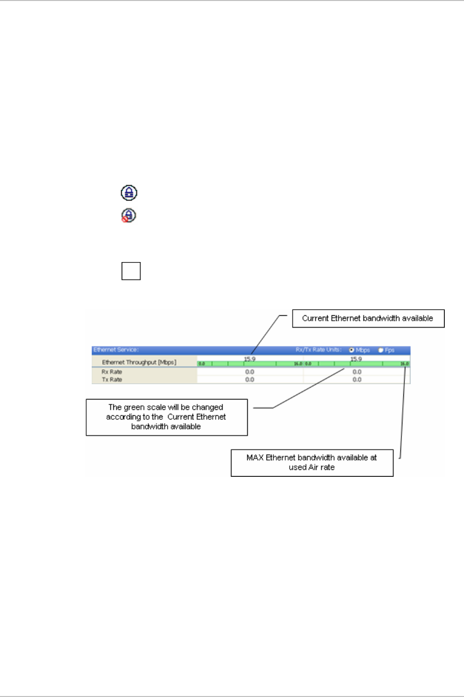
WinLink 1000 Installation and Operation Manual Chapter 3 Operation
Network mode to the local unit – using IP of the local unit
Over the Air connection - using IP address of the remote for
over the air connection
Local mode using broadcast - direct connection to IDU LAN
port without IP address. This mode is only recommended
when the managed PC is connected directly to the IDU (no
network involved) the managed PC must have a static IP
configured. (No DHCP)
Encryption icon showing if the link is encrypted
encrypted link
Link Password Validation failed. The link is encrypted with
default keys. Service and configuration is unavailable. Need to
change the link password in either site
No Encryption – an older release is used. No encryption is
available
Figure
3-5. Ethernet Bandwidth Indication
Æ To change link configuration parameters:
1. In the Main menu, click Configure Link.
The Configure Link wizard appears. See
Chapter 4
for
configuration details.
2. Click Next.
3. Continue through the configuration wizard and define the Link
name and ID, Channel, Rate and Services.
4. Once you finish changing configuration parameters, click Finish.
Managing WinLink 1000 3-9

Chapter 3 Operation WinLink 1000 Installation and Operation Manual
The system takes a few seconds to activate the link with the new
configuration.
3.5 Turning Off WinLink 1000
Æ To turn off WinLink 1000:
1. Exit the management application.
2. Remove the AC/DC converter power cord from the mains.
3-10 Turning Off WinLink 1000

Chapter 4
Configuration
This chapter describes configuration procedures, which are performed
after the physical installation of the local and remote WinLink 1000
units and the Installation Link wizard has been performed. A second
wizard is used to redefine the configuration parameters if necessary.
Both sites in the link are defined simultaneously.
The following parameters are configured via the Configuration Wizard:
• System parameters
• Frequency channel
• Air interface rate
• Service parameters
• TDM
• Hub Site Synchronization Settings.
The following parameters are configured via the Configuration dialog
box.
• Transmit power
• Management and trap addresses
• Bridge mode
• Ethernet mode
• Community values.
Note
For HSS screens specific to WinLink 1000-ACCESS-CL units see
Appendix F
.
4.1 Configuring the System Parameters
After installing the link, the system configuration can be modified.
Note
All parameter changes are automatically applied to both sides of the
link.
Configuring the System Parameters 4-1

Chapter 4 Configuration WinLink 1000 Installation and Operation Manual
Æ To change general parameters:
1. In the Main menu, click the Link Configuration button.
2. The Configuration wizard opens (
Figure 4-1
).
Figure
4-1. Configuration Link Wizard
3. Click Next.
4. The Link Configuration dialog box appears (see
Figure
4-2
).
4-2 Configuring the System Parameters
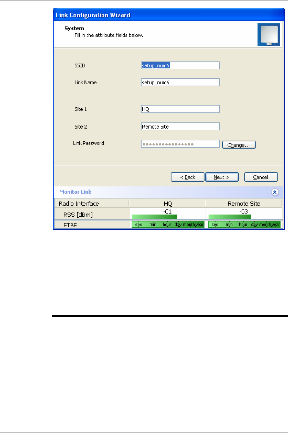
WinLink 1000 Installation and Operation Manual Chapter 4 Configuration
Figure
4-2. Link Configuration, System dialog box
5. In the System dialog box, enter the new data for the link. All fields
with a white background can be edited.
6. Click Next.
The Frequency dialog box appears.
4.2 Selecting Channels
The user is required to define the operating frequency channel. Newer
versions of WinLink 1000 have a feature called Automatic Channel
Select. This allows you to define several allowable frequency channels
that WinLink 1000 can change to in event that interference is detected
on the channel in use.
• For WinLink 1000 with the Automatic Channel Select feature see
WinLink 1000 with Automatic Channel
Select.
Selecting Channels 4-3
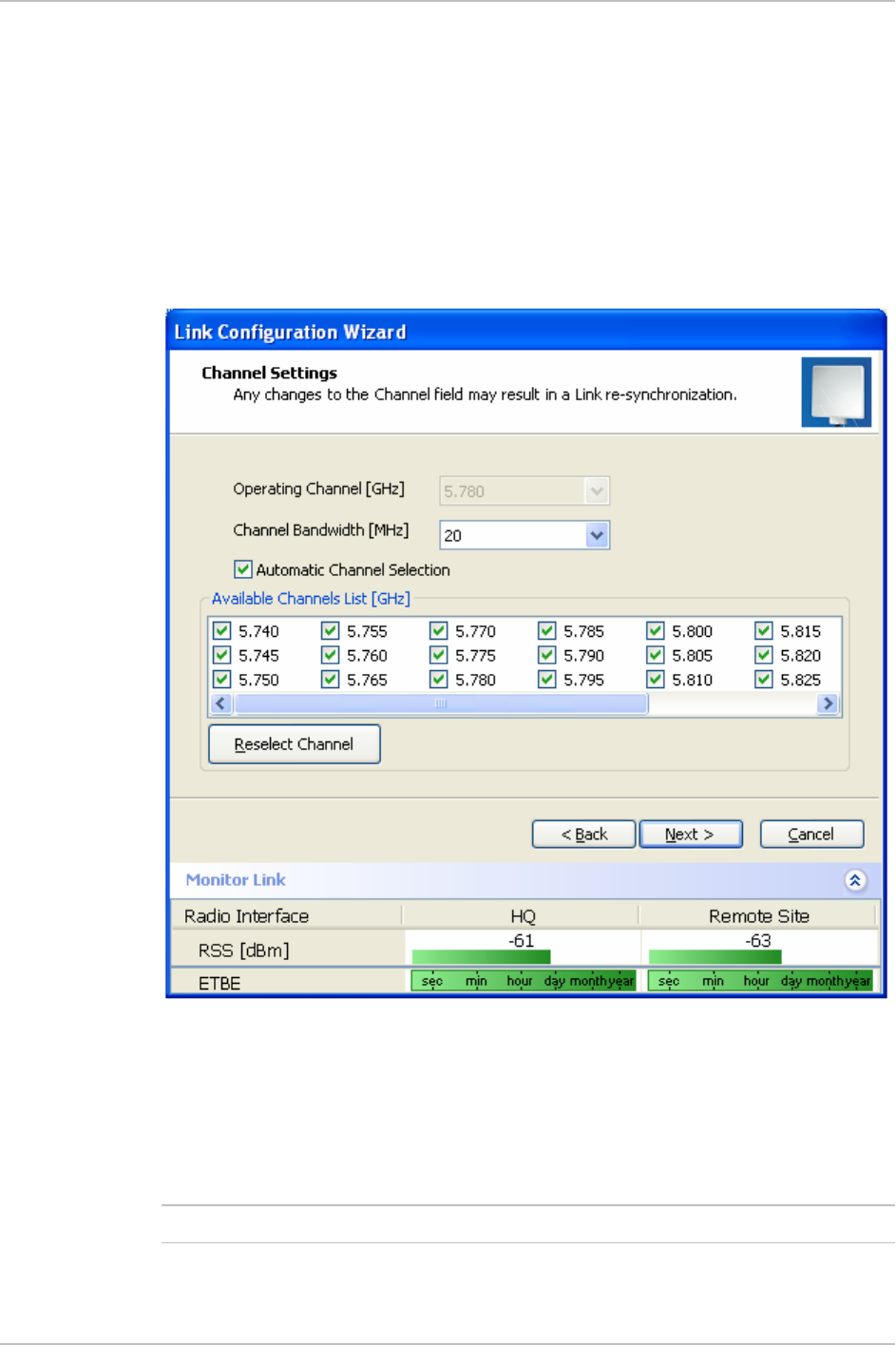
Chapter 4 Configuration WinLink 1000 Installation and Operation Manual
• For WinLink 1000 5.4 GHz ETSI version see
WinLink 1000 5.4 GHz
ETSI
Version.
• For WinLink 1000-BRS systems see
WinLink 1000 BRS Version.
WinLink 1000 with Automatic Channel Select
Automatic Channel Select enables WinLink 1000 to change frequency
channels automatically if interference is detected on the current
operating channel.
Figure
4-3. Channel Select dialog box - Automatic Channel Select
Æ To define automatic channel selection:
1. Select the main frequency from the Operating Channel menu.
2. Select the required Bandwidth 5, 10, or 20 MHz.
Note
F2.x GHz versions operate at 10 or 20 MHz steps only.
3. Click the check box if Automatic Channel Selection is required.
4-4 Selecting Channels

WinLink 1000 Installation and Operation Manual Chapter 4 Configuration
4. Click the check boxes in the Available Channels List of all the
allowable channels that can be automatically selected.
5. If you are not satisfied with the channel that is selected
automatically, click Reselect Channel.
A new channel will be selected from one of the Available
Channels that have been defined.
Selecting Channels 4-5

Chapter 4 Configuration WinLink 1000 Installation and Operation Manual
Note
By clicking Reselect Channel, the ODU starts scanning all the channels
from the available channels list and looks for radio frequency activity in
each of the channels. It tries to select the optimal pure channel. If
another channel is required, the operating channel that the ODU finds
most pure must be removed from the available channel list.
6. Click Next.
The Rate Select box appears.
WinLink 1000 5.4 GHz ETSI Version
In accordance with ETSI, unlicensed wireless data equipment is not
allowed to interrupt radar services. Therefore, if WinLink 1000 detects
Radar interference it automatically changes the frequency channel. This
feature is termed Dynamic Frequency Selection (DFS). According to the
standard, a channel with active Radar is prohibited from use for 30
minutes. Before any transmission, WinLink 1000 probes a channel for
Radar signals for a period of 60 seconds.
In the 5.4 GHz ETSI version, the Automatic Channel Selection is
selected by default and a minimum of two channels must be defined as
available.
4-6 Selecting Channels

WinLink 1000 Installation and Operation Manual Chapter 4 Configuration
Figure
4-4. Channel Select dialog box (DFS, ETSI requirement)
The sign on the configuration Wizard and Status bar indicates that
the radar detection is on.
Æ To define automatic channel selection in the 5.4 ETSI version
1. Select the main frequency from the Operating Channel menu.
Note
Automatic Channel Selection is selected by default.
2. Click at least two check boxes in the Available Channels List of all
the allowable channels that can be automatically selected.
Note
Installation will not continue until at least two channels are defined.
Selecting a new channel causes the system quality to change. The
quality bar shows the adjustment until the system finds the best
quality link.
Any channel selected is evaluated for 60 seconds; therefore this
selection process may take a few minutes.
Selecting Channels 4-7

Chapter 4 Configuration WinLink 1000 Installation and Operation Manual
3. If you are not satisfied with the channel that is selected
automatically, click Reselect Channel.
A new channel will be selected from one of the Available
Channels that have been defined.
Note
The reselection process may take a few minutes.
4. Click Next.
The maximum rate is selected according to the link conditions
The quality bar shows the adjustment until the system finds the
best quality link.
7. Click Next.
The Service Parameters dialog box appears.
WinLink 1000 BRS Version
Both sites in a BRS Link must be configured identically.
Any changes to the frequency settings cause the link to re-
synchronize. A short loss of servi e will occur during re-
synchronization.
c
Not
e
Æ To Configure BRS Channel Settings
1. Set the Band Plan.
2. Select the Bandwidth required,
Single Band
Double Band
3. Select the Frequency from the pull-down menu.
4. Click Next. The system is re-synchronized to the changes.
4-8 Selecting Channels
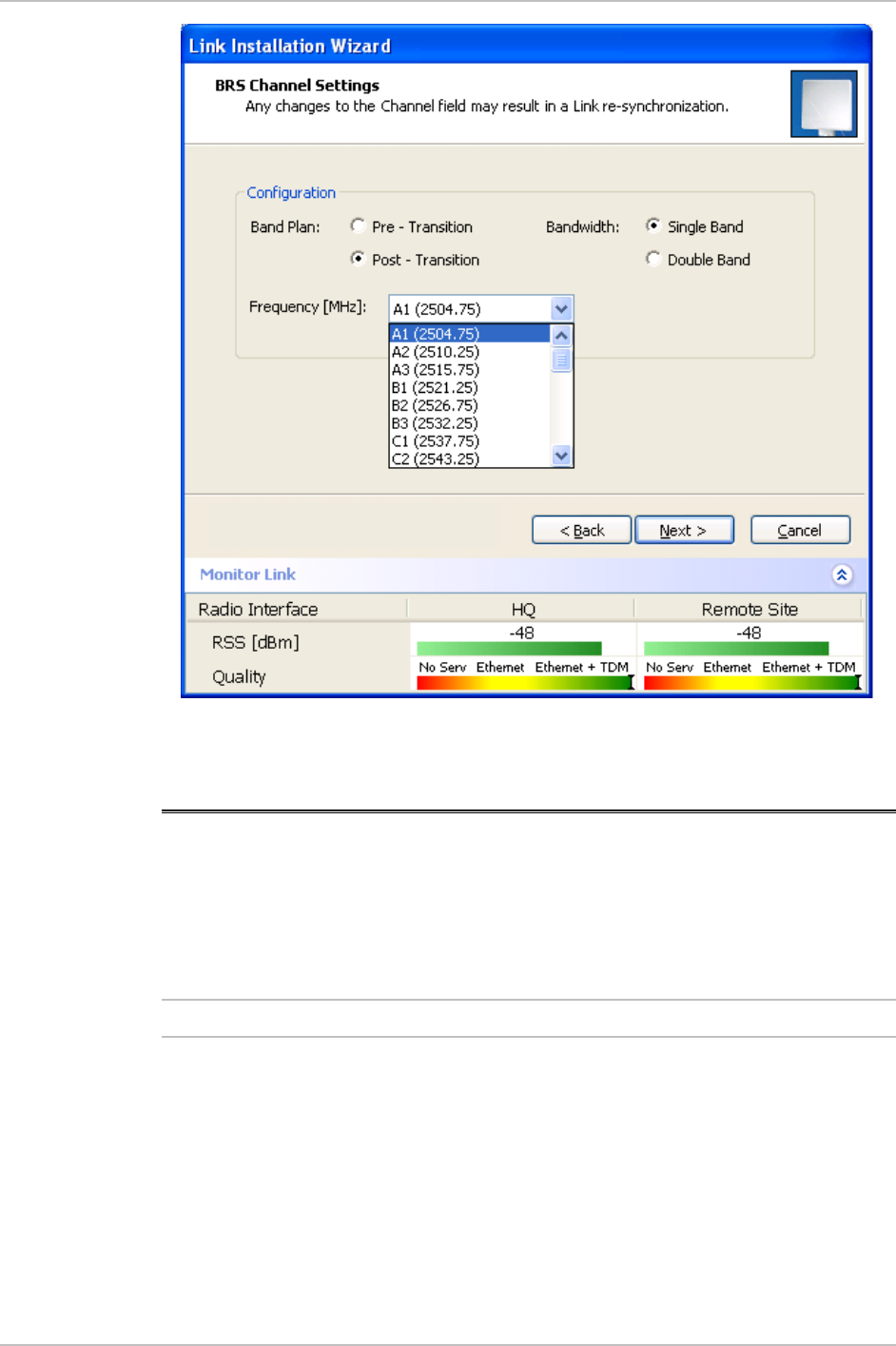
WinLink 1000 Installation and Operation Manual Chapter 4 Configuration
Figure
4-5. BRS Channel Settings Post-Transition
4.3 Configuring Service Parameters
The user defines the type of service required, Ethernet Only or Ethernet
with TDM. The bandwidth remaining available for Ethernet if TDM
services are required is shown in the dialog box.
WinLink 1000-ACCESS versions are Ethernet Only.
In the Service Parameters dialog box select if WinLink 1000 is to
provide E1/T1,
(x1 or x2 for IDU-E, or x4 for IDU-C). Define the required transmission
rate, and the distance between the sites.
Note
Æ To configure E1/T1 and Ethernet services:
1. In the Service dialog box, select one of the following:
Ethernet plus a number of E1/T1 channels (see
Figure
4-6
).
Configuring Service Parameters 4-9

Chapter 4 Configuration WinLink 1000 Installation and Operation Manual
Ethernet data only (see
Error! Reference source not found.
).
2. Select the transmission rate required.
Adaptive
12 Mbps
18 Mps
24 Mbps
The default rate is Adaptive. ACCESS versions only operate in
Adaptive mode.
Adaptive Modulation - The system changes modulation
automatically depending on channel characteristics in order to
guarantee continuation of service. The adaptive modulation enables
the user to maximize Ethernet throughput without degradation of
the TDM service quality. When Ethernet only service is used, the
adaptive modulation enables improving the Ethernet performance
in case of air performance degradation (periodical interference or
RSS changes).
In event of interference at one site, there is no need to use a lower
modulation at the other site (as in previous versions). In such a case
the actual rate changes automatically only at the problematic site,
while the second side of the link maintains the highest rate possible
(Asymmetric).
Adaptive modulation can be changed in both Installation and
Configuration wizards.
3. Type in the distance between the sites.
If TDM services are selected, then the Evaluate icon shows on
the screen whilst the maximum rate is evaluated.
When evaluation is complete the icon changes and the following
message is shown:
Service has been evaluated, click Next to continue.
4. Click Next.
The TDM Parameters dialog box or the Finish screen appears
depending on which services were selected.
4-10 Configuring Service Parameters
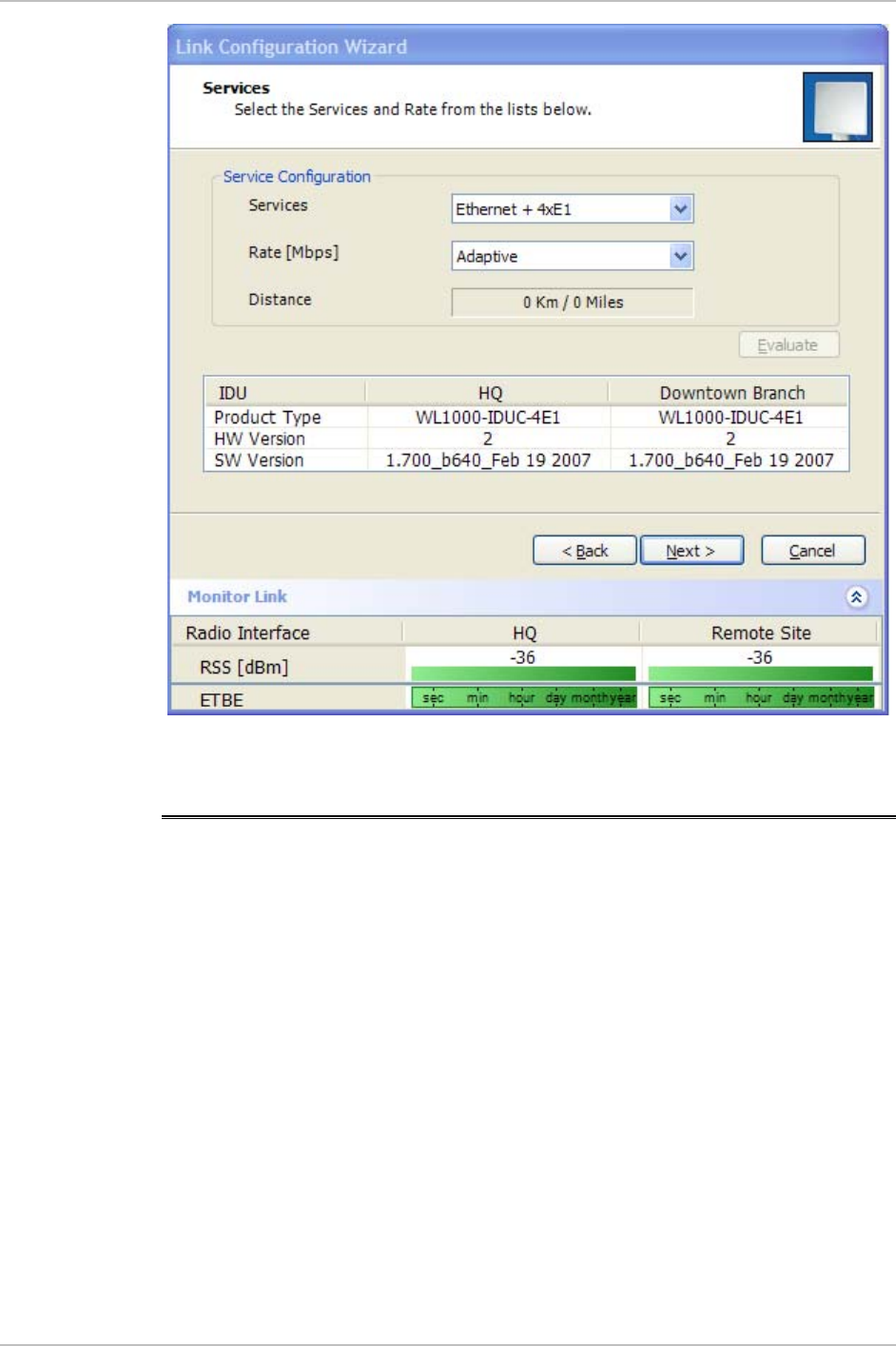
WinLink 1000 Installation and Operation Manual Chapter 4 Configuration
Figure
4-6. Service Parameters Dialog Box, E1/T1 Interface
4.4 Configuring TDM Operation
Setting the Clock Configuration
The TDM clock feature is enabled in all carrier class IDU’s in addition to
new hardware IDU’s. A TDM dialog box will appear where IDU supports
the clocking configuration feature (see
Figure
4-7
and
Figure
4-8
).
A new master clock configuration option is available in the Link
Configuration Wizard. The automatic mode selects the clock from the
first trunk that is working in normal mode (or is configured to loop-
back maintenance). If a specific trunk is selected, this trunk shall be
used as the system master regardless of the trunks state. The current
master clock trunk is also displayed.
Configuring TDM Operation 4-11

Chapter 4 Configuration WinLink 1000 Installation and Operation Manual
Figure
4-7. TDM clock dialog box for T1 IDU
4-12 Configuring TDM Operation
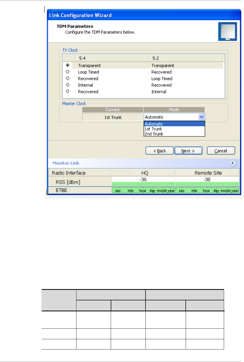
WinLink 1000 Installation and Operation Manual Chapter 4 Configuration
Figure
4-8. TDM clock dialog box for E1 IDU
If TDM services are selected then the TDM parameters dialog box
appears.
The TDM Parameters dialog box contains five working modes; select
the appropriate clock mode according to your application. Choosing
one of these modes sets the TDM clock behavior on both sides of the
link. The user equipment must be configured as described
Table
4-1
.
Table
4-1. TDM Clock Modes
Unit clock mode User equipment side
Local Unit Remote Unit HQ side Branch side
1 Transparent Transparent Internal/Recov
er
Internal/Recov
er
2 Loop Time Recover Internal Recover
3 Recover Loop Time Recover Internal
Configuring TDM Operation 4-13

Chapter 4 Configuration WinLink 1000 Installation and Operation Manual
Unit clock mode User equipment side
Local Unit Remote Unit HQ side Branch side
4 Internal Recover Recover Recover
5 Recover Internal Recover Recover
4-14 Configuring TDM Operation

WinLink 1000 Installation and Operation Manual Chapter 4 Configuration
Transparent/Transparent
WinLink 1000 transparently regenerates the clock from line
clock side to Tx clock on the opposite side of the link.
Loop time/Recover
The local unit receive clock is the transmit clock on both sides
of the link.
Recover/Loop time
The remote unit receive clock is the transmit clock on both
sides.
Internal/Recover
The local unit internal oscillator generates the clock while the
remote unit recovers this clock.
Recover/Internal
The remote unit internal oscillator generates the clock while the
local unit recovers this clock.
The Line code option is used with T1 Systems.
Setting the T1 Line Code
The T1 line code can be set as B8Zs or AMI in the TDM Parameters
dialog box.
The default is B8ZS.
This dialog box is available only when TDM service was selected in the
previous Services dialog box.
Not
e
Not
e
Æ To change the line code
1. Run the Configuration wizard until you reach the Services dialog
box.
2. Verify that T1 services have been selected.
3. Click Next to open the TDM Parameters dialog box.
4. Set the line code to B8ZS or AMI as required.
5. Click Next.
Setting the TDM Backup (IDU-R only)
IDU-R units have two E1 trunk lines, one for WinLink 1000 air interface
via the ODU, and the second external equipment such as a PBX. The
TDM backup screen is displayed in IDU-R systems only.
Configuring TDM Operation 4-15

Chapter 4 Configuration WinLink 1000 Installation and Operation Manual
The external equipment status is displayed on the Main screen of the
Manager in IDU-R systems.
Æ To use the Backup Mode
1. Click Enabled Backup Mode.
2. Set which link is backup link; either WinLink 1000 or the external
equipment.
The second link becomes the main link.
3. Click Next to continue.
Æ To disable the Backup mode
1. Click Disable Backup Link
2. Set which link is the Main Link; either WinLink 1000 or the external
equipment.
3. Click Next to continue.
4-16 Configuring TDM Operation
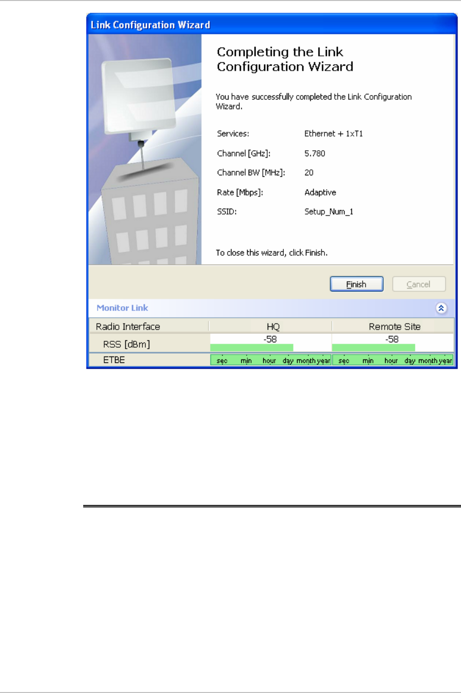
WinLink 1000 Installation and Operation Manual Chapter 4 Configuration
Figure
4-9. Configuration Link, Finish screen
The Finish screen appears, showing a summary of the link
configuration (see
Figure
4-9
).
• Click Finish to complete the configuration wizard.
The Main screen is displayed.
4.5 Editing the Configuration Parameters
You can edit the configuration parameters for each site individually
without running a wizard.
From the Configuration dialog box, (see
Figure
4-10
) the following
functions are available by selecting the items on the left of the dialog
box:
System Edit the contact person and location details. View the
system details
Editing the Configuration Parameters 4-17

Chapter 4 Configuration WinLink 1000 Installation and Operation Manual
Air Interface Change the transmit power
Inventory View the hardware and software inventory.
Management Configure the IP address, Subnet Mask, Default
Gateway, and the Trap Destination.
Security Change the Community Values and the Link Password
Date and Time Set the date and time of the server and of the system.
Advanced Configure the Bridge, define the LAN connection and set
the external alarm inputs.
From the Configuration dialog box, the following functions are
available by clicking the buttons at the top of the dialog box:
Backup Save a backup.ini file with the current configuration.
Restore Load the backup.ini file created by the backup.
Installation Mode Return to Installation Mode for the entire link.
Selecting the Mute check box before clicking the Install
Mode button mutes the Beeper.
Mute Mutes the Beeper at startup. Reactivate the beeper during
alignment.
Æ To edit the Configuration Parameters:
1. Click Configuration from the main menu.
2. Select which site to configure.
The Configuration dialog box opens. (See
Figure
4-10
)
4-18 Editing the Configuration Parameters
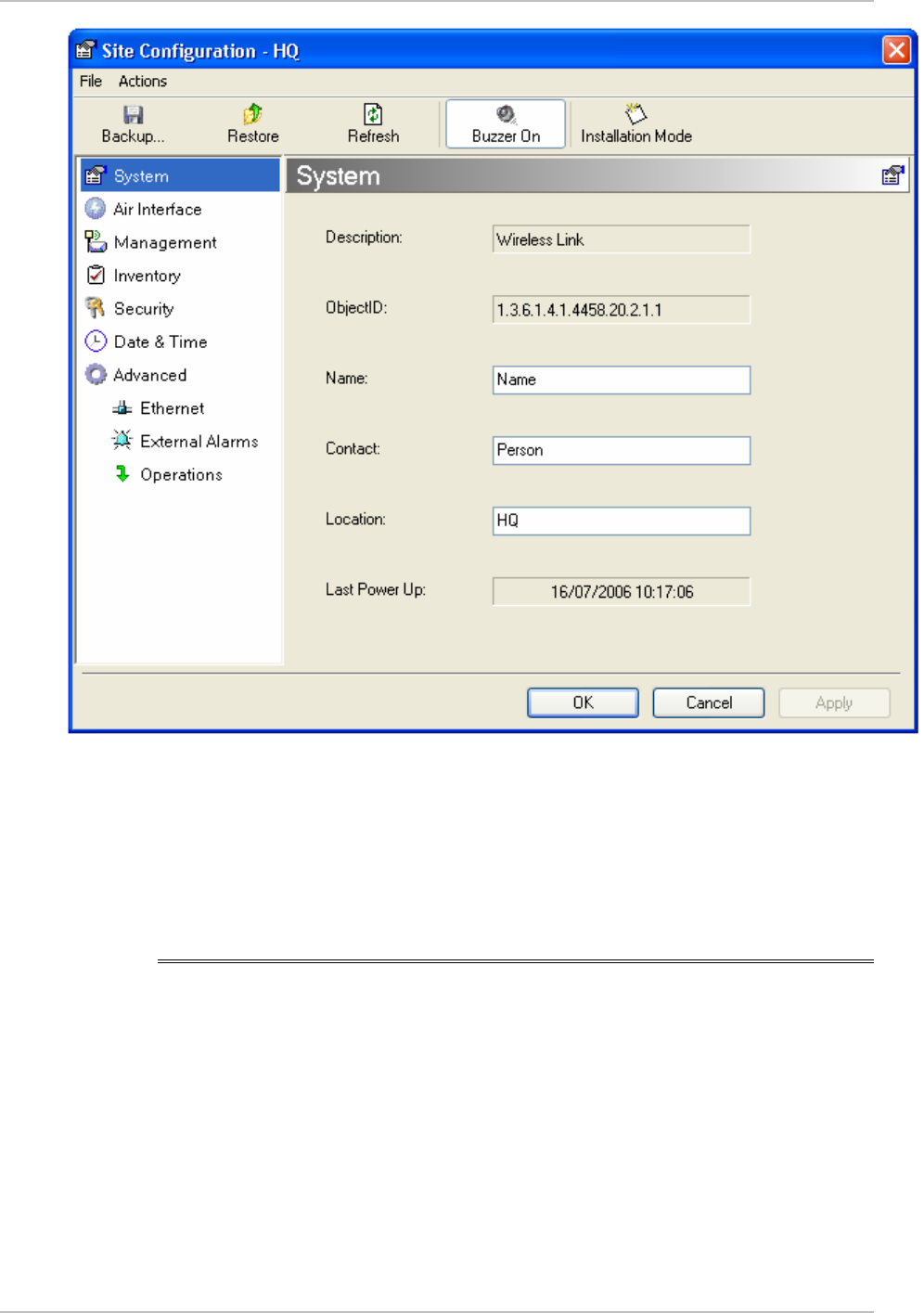
WinLink 1000 Installation and Operation Manual Chapter 4 Configuration
Figure
4-10. Configu ation Dialog Box r
3. Select the appropriate item in the left hand list to open a dialog
box.
4. Click Apply to save the changes.
4.6 Changing the Transmit Power
Each site can have a different transmit power level.
Æ To change the Transmit Power:
1. Click Configuration from the main menu.
2. Select which site to configure.
The Configuration dialog box opens.
3. Select Air Interface. (See
Figure
4-11
)
Changing the Transmit Power 4-19

Chapter 4 Configuration WinLink 1000 Installation and Operation Manual
4. Select the required Transmit Power Level. Table 4-2 shows the
available power limits for each WinLink 1000 system.
5. Click Apply to save the changes.
Figure
4-11. Changing the Transmit Power
4-20 Changing the Transmit Power

WinLink 1000 Installation and Operation Manual Chapter 4 Configuration
Table
4-2. Typical Transmit Power Limits
Regulation Version Min Tx
[dB]
Max Tx
[dB]
MaxTx at
36 Mbps
[dB]
MaxTx
at
48 Mbps
[dB]
Power
Control
F58 4 16 14 10 Yes
F58/EXT 4 16 14 10 Yes
F49 14 15 15 14 No
F53 -3 8 8 8 Yes
F53/EXT 3 3 3 3 No
F24 18 18 18 18 No
FCC
F53HP 10 16 14 10 Yes
F54 2 8 8 8 Yes
F54/ETSI 2 8 8 8 Yes
ETSI
F54-
HG/EXT
-3 3 3 3 Yes
4.7 Defining the Management Addresses
Each site must be configured separately, first site A then site B.
Æ To define the Management Addresses:
1. Click Configuration from the main menu.
2. Select which site to configure.
The Configuration dialog box opens.
3. Select Management (see
Figure
4-12
).
4. Enter the IP address of the ODU in the IP address field.
Note
If performing configu ation from the WinLink manager, the IP address
is entered in the login screen (
r
Figure 2-4)
5. Enter the Subnet Mask.
6. Enter the Default Gateway.
Defining the Management Addresses 4-21
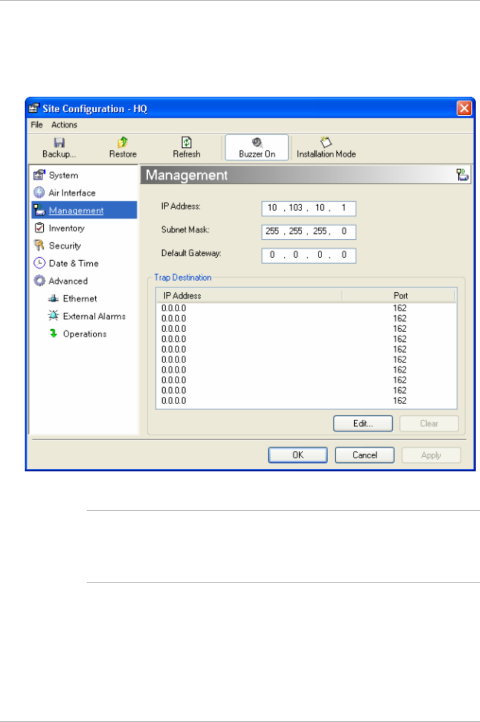
Chapter 4 Configuration WinLink 1000 Installation and Operation Manual
7. Enter the Trap Destination. This is the IP address of the PC running
the management application. The event log will be stored at this
address.
8. Click Apply to save the changes.
Figure
4-12. Configuration, Management
Notes
The Installation mode button opens the Link Installation wizard to
reinstall the link.
The Backup and Restore buttons are for saving and restoring the
configuration files.
4-22 Defining the Management Addresses

WinLink 1000 Installation and Operation Manual Chapter 4 Configuration
4.8 Setting the Date and Time
Æ To set Date and time
The ODU maintains a date and time value. The date and time value
should be synchronized with any Network Time Protocol (NTP) version
3 compatible server1. On power-up the ODU configures the initial date
and time using an NTP server. If the server IP is not configured or is
not reachable, a default time is set. When configuring the NTP server
IP, you should also configure the offset from the Universal Coordinated
Time (UTC). If there is no server available, you can either set the date
and time, or you can set the manager workstation time. Note that
manual setting is not recommended since reset, power up, or
synchronization with an NTP server will override the setting.
•
The NTP uses UDP port 123. If a firewall is configured between the
ODU and the NTP ser er this port must be openedv
2
.
•
It can take up to 8 minutes for the NTP to synchronize the ODU date
and time.
1. Click Configuration from the main menu.
2. Select which site to configure.
The Configuration dialog box opens.
3. Select Date & Time (see
Figure
4-13
).
Not
e
1 Windows XP is configured by default as a server.
2 Windows XP command w32tm /stripchart /computer:<server IP> can be use to
check the NTP server connectivity
Setting the Date and Time 4-23

Chapter 4 Configuration WinLink 1000 Installation and Operation Manual
Figure
4-13. Date & Time configuration
4. If entering an address for the NTP Server, click Clear, and then
enter the new address.
5. Set the Offset value.
6. To manually set the date and time, click Change (
Figure
4-14
) and
edit the new values.
Figure
4-14. Manually changing date and time
4-24 Setting the Date and Time
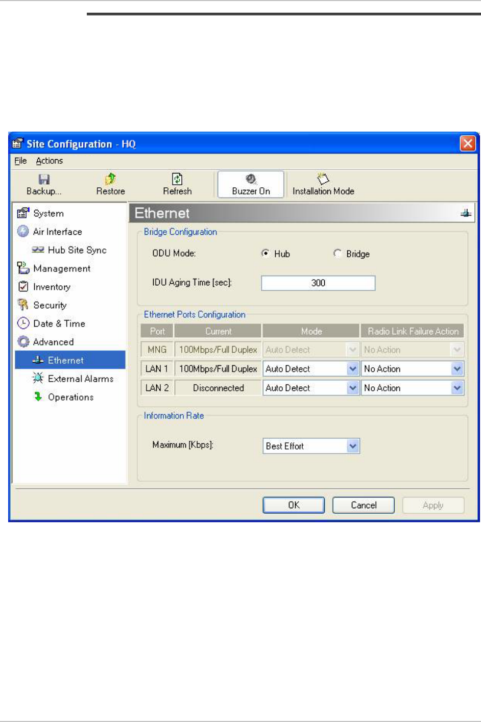
WinLink 1000 Installation and Operation Manual Chapter 4 Configuration
4.9 Configuring the Bridge
Bridge configuration is required in various network topologies, such as
protection (1+1) and ring application. The bridge configuration
parameters are located under the Advanced tab of the Configuration
dialog box (
Figure
4-15
).
Figure
4-15. Advanced Configu ation-Ethernet r
ODU Bridge Mode
This parameter controls the ODU mode with two optional values,
• Hub Mode – in Hub mode the ODU transparently forwards the all
the packets over the wireless link.
• Bridge Mode – In Bridge mode the ODU performs both learning and
aging, the aging time of the ODU is fixed at 300 seconds.
Configuring the Bridge 4-25

Chapter 4 Configuration WinLink 1000 Installation and Operation Manual
Changing these modes requires system reset.
Note
IDU Aging time
This parameter controls the IDU aging time.
The IDU has a 2047 MAC address-learning table. The aging time
parameter controls the time each MAC address is dropped from the
table.
Default value is 300 seconds.
Any change to these parameters is effective immediately.
Each side of the link can be configured separately.
The following list details common configurations; both sides are must
be configured with the same parameter.
Notes
• Standard (Default) Configuration for Ethernet Applications
Set IDU aging to 300 seconds, ODU set to Bridge mode,
Figure
4-15
.
• Fast aging mode – for rapid network topology changes
Set IDU aging to one second, ODU set to Hub mode.
• Hub Mode
The ODU is set to HUB mode. IDU aging is not applicable.
• Ethernet Bridge
The ODU is set to Bridge mode. The IDU aging is not applicable.
4.10 Configuring Ethernet Mode
The Ethernet mode is configurable for line speed (10/100BaseT) and
duplex mode (half or full duplex). WinLink 1000 provides an Auto
detect feature where the line speed and duplex mode are detected
automatically using autonegotiation. Use the manual configuration
when external equipment does not support autonegotiation. The
default setting is Auto Detect. (See
Figure
4-15
).
The maximum Ethernet Information Rate can be limited via the pull
down menu. The default setting is Best Effort.
It is not recommended to configure the port that i used for the
management connection, since a wrong configuration can cause
management disconnection or Ethernet services interruption.
s
Note
4-26 Configuring Ethernet Mode

WinLink 1000 Installation and Operation Manual Chapter 4 Configuration
Æ To configure the Ethernet Mode:
1. From the Configuration menu, select the site to reconfigure.
The Site Configuration dialog box opens.
2. Click Advanced > Ethernet.
3. In the Ethernet Ports Configuration pane, use the drop-down menu
to select the LAN configuration.
4. Click Apply to save the changes.
Note
It is possible to close the Ethernet service by disconnecting the
Ethernet port. The user should be aware that it i possible to close the
port and not have any access to the device. If this should occur the
workaround is as follows:
s
• Connect the system from the remote site
• Connect via other Ethernet port (IDU-C)
• Power down the equipment and connect immediately after the
power up (the fastest way is to enter install mode).
4.11 Setting the Maximum Information Rate
The maximum Ethernet throughput of the link can be limited. The
default setting is Best Effort, where the highest information rate
available for the link conditions and settings is used. (See
Figure
4-15
)
Æ To set the Ethernet information rate:
1. From the Configuration menu, select the site to reconfigure.
The Configuration dialog box opens.
2. Click Advanced > Ethernet
3. In the Information Rate pane, use the drop-down menu to select
the maximum Information Rate.
Select Other to define the throughput with 8 Kbps resolution
Select Best Effort for the highest information rate possible for the
link conditions and settings.
4. Click Apply to save the changes.
Not
e
WinLink 1000-ACCESS systems have a maximum rate of 2048 kbps.
Setting the Maximum Information Rate 4-27

Chapter 4 Configuration WinLink 1000 Installation and Operation Manual
4.12 Changing Community Values
The ODU communicates with the management application using
SNMPv1 protocol. The protocol defines three types of communities:
• Read-Only for retrieving information from the ODU
• Read-Write to configure and control the ODU
• Trap used by the ODU to issue traps.
The community string must be entered at login. The user must know
the password and the correct community string in order to gain access
to the system. A user may have read-only privileges.
It is not possible to manage the ODU if the read-write or the read
community values are forgotten. A new community value may be
obtained from technical support for the purpose of setting new
community; the serial number or the MAC address of the ODU must be
supplied.
The manager application and the ODU use the community strings
public-bru1 for the local unit and public-bru4097 for the remote unit.
These are the factory defaults, but can only be used one time on the
first installation.
A new community string must be set when entering the system for the
first time. The read-write community and read-only community have a
minimum of five alphanumeric characters. (Bru1 and bru4097 are not
permitted). Changing the trap community is optional by clicking the
check box.
Note
Editing Community Strings
The community change dialog box is available from the Configuration
> Security tab. Both read-write and read-only communities must be
defined.
On entering for the first time, use netman as the current community.
The community string must be changed when entering the system for
the first time, and the community string netman cannot be used again.
Æ To change a community:
1. From the Configuration dialog box, select the Security tab
2. Type the current read-write community (default is netman).
4-28 Changing Community Values
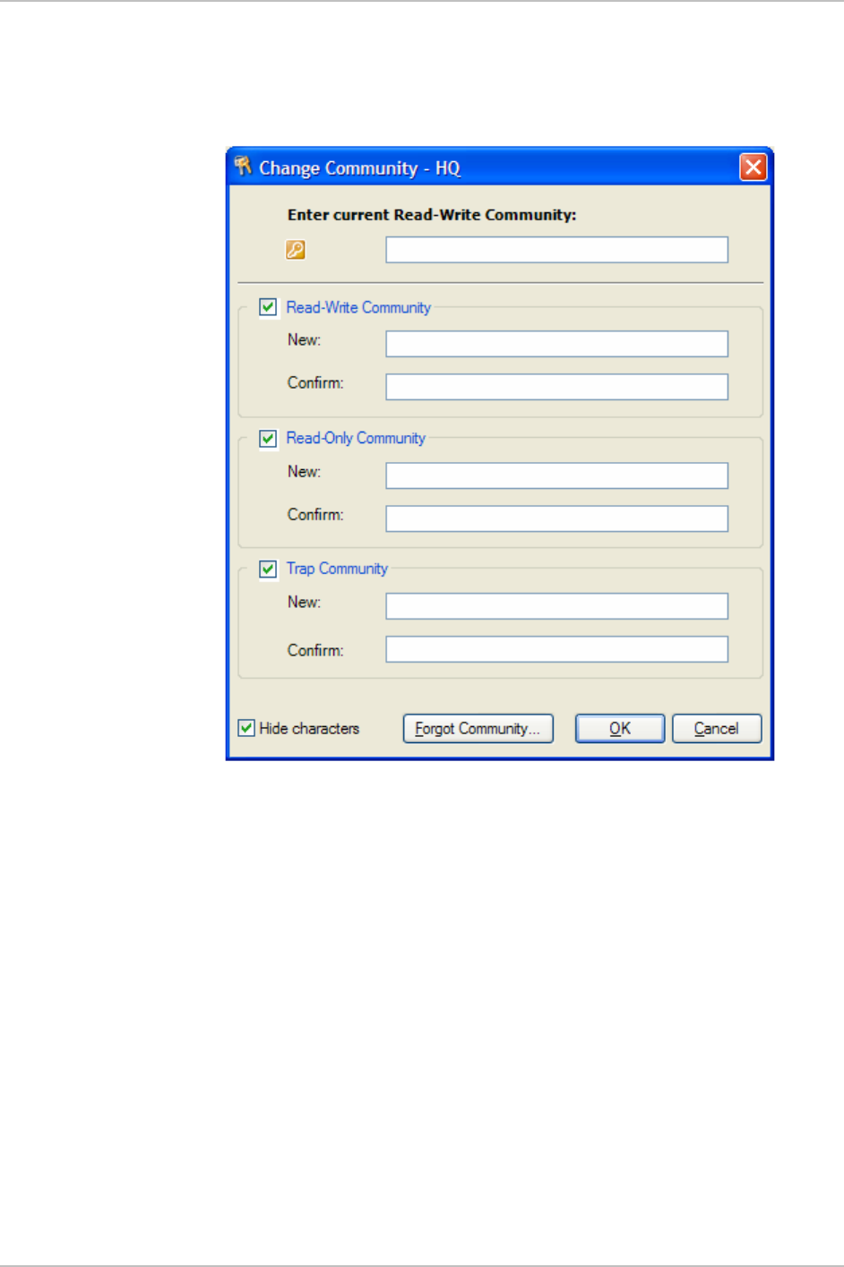
WinLink 1000 Installation and Operation Manual Chapter 4 Configuration
3. Select the communities to be changed by clicking the check box.
4. Type the new community and re-type to confirm.
5. Click OK to save.
Figure
4-16. Changing the Community String
Changing Community Values 4-29
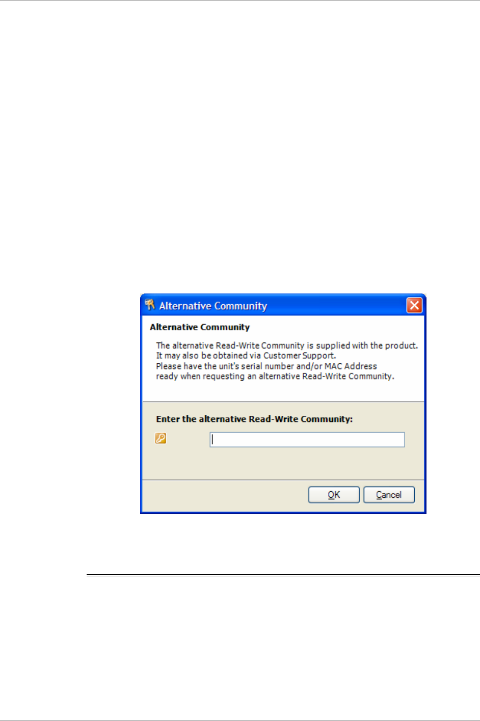
Chapter 4 Configuration WinLink 1000 Installation and Operation Manual
Forgotten Community string
If the read-write community string is unknown, an alternative
community key can be used. The alternative community key is unique
per ODU and can be used only in order to change the community
strings. The alternative community key is supplied with the product,
and it is recommended to keep it safe.
If both the read-write community and the alternative community key
are unavailable, then an alternative community key can be obtained
from customer support using the ODU serial number or MAC address.
The serial number is located on the product, and the MAC address is
displayed in the manager inventory tab.
When you have the alternative community key, click the Forgot
Community button and enter the Alternative Community (
Figure
4-17
).
Then reconfigure the read-write community string.
Figure
4-17. Alternative Community Dialog box
4.13 Changing Passwords
There are two passwords necessary to use the WinLink 1000 system.
The first is encountered when running the management software, the
second, the link Password is used for encryption purposes and is found
when installing or configuring the link.
4-30 Changing Passwords

WinLink 1000 Installation and Operation Manual Chapter 4 Configuration
Changing the Management Password
Æ To change the management password
1. From the Tools menu, select Change Password
2. The Change Password dialog box appears.
3. Enter current password, and new password.
4. Click OK to confirm.
Changing the Link Password
WinLink 1000 Radio Link is encrypted using Advanced Encryption
System (AES) using a 128 bit dynamic key. During the installation
process a Link Password must be set. An Initial encryption key is
generated. Each time a link is established the Encryption key is
validated. If the validation failed the link is established but no service
or configuration is allowed. In this state the user can change the link
password of each of the sites.
Æ To change the Link Password:
1. From the Configuration dialog box, select the Security tab
2. Click Change next to the Link Password field box.
The Change Link Password dialog box appears.
3. Enter the current link password.
4. Enter the new password.
5. Enter the new password again in the Confirm box.
Forgotten the Link Password
In case of a forgotten link password, the user may enter the key
password supplied with the product. The key password may be
obtained from customer support after validation of the device serial
number or MAC address. The user may change the link password of
both sides of the link at any time using the Link Configuration Wizard.
Changing Passwords 4-31

Chapter 4 Configuration WinLink 1000 Installation and Operation Manual
Æ To enter the key password:
1. From the Configuration dialog box, select the Security tab.
2. Click Change next to the Link Password field box.
The Change Link Password dialog box appears.
3. Click the Forgot Link Password button.
The Key Link Password dialog box appears.
4. Type the key link password.
5. A new link password may now be set.
4-32 Changing Passwords

WinLink 1000 Installation and Operation Manual Chapter 4 Configuration
4.14 Muting the Beeper
The ODU beeper starts beeping as soon as power is supplied, and
continues until the ODUs are aligned and the link established.
It is possible to mute the beeper until the alignment procedure is to be
performed.
Æ To mute the beeper:
1. Click on Configuration in the Menu bar and select the relevant site.
The Configuration dialog box opens.
2. In the Configuration dialog box, click the Buzzer button. The button
toggles between on and off.
3. The Beeper stops.
Æ To restore the beeper:
1. Click Configuration in the Menu bar and select the relevant site.
The Configuration dialog box opens.
2. In the Configuration dialog box, click the Buzzer button. The button
toggles between on and off.
3. The Beeper starts.
4.15 Setting External Alarm Inputs
The IDU-C has two external alarm inputs in the form of dry-contact
relays. The Alarm interface is located on the front panel of the IDU-C
and is a 9-pin D-type female connector, see
Appendix A
for the
pinout. The user enables or disables each of the alarms and can
configure the text that appears in the alarm trap. The ODU sends the
alarm within less than a second from actual alarm trigger.
Æ To set the external alarm inputs:
1. Open the Site Configuration Alarms configuration by clicking
Configuration > Advanced.
Setting External Alarm Inputs 4-33

Chapter 4 Configuration WinLink 1000 Installation and Operation Manual
Figure
4-18. External Alarm Configuration
2. Enter a description of the alarms in the fields.
3. Click Apply to save.
4.16 Managing Configuration Files
Saving WinLink 1000 Configuration in a File
WinLink 1000 management software allows you to save configuration
parameters of the local and remote units on the management station
as an INI file. Each site is saved in a separate INI file.
Æ To save the configuration in a file:
1. Click Configuration from the main menu.
4-34 Managing Configuration Files

WinLink 1000 Installation and Operation Manual Chapter 4 Configuration
2. Select which site to backup.
The configuration dialog box opens.
3. Click Backup.
4. In the Save As dialog box, indicate in which folder and under what
name configuration file is to be saved, and click Save.
Restoring a Configuration File
Configuration files (*.ini) can be uploaded from the management
station. Verified configuration files can be distributed to other units
that use the same configuration.
Æ To restore a configuration file:
1. From the Configuration menu, select the site to reconfigure.
The Configuration dialog box opens.
2. Click Restore.
3. From the Open dialog box select *.ini file to upload and click OK.
4.17 Reinstalling the Link
It may be necessary to reinstall the link if the ODUs should need to be
realigned.
Reinstalling the link causes both sites to go into install mode.
Not
e
Æ To reinstall the link:
1. Click Configuration in the Menu bar and select any one of the sites.
The Configuration dialog box opens.
2. Click the Install Mode button in the Configuration dialog box.
A message box asking if you want to enter install mode appears.
3. Click Yes to continue.
WinLink 1000 enters install mode and the beeper starts beeping.
4. Realign the ODUs and complete the Installation wizard (see
Chapter2
).
Reinstalling the Link 4-35

Chapter 4 Configuration WinLink 1000 Installation and Operation Manual
4.18 Resetting WinLink 1000
Resetting the link causes service disconnection.
In order to maintain the link configuration, reset the remote WinLink
1000 first
.
Note
Æ To reset WinLink 1000:
1. From Maintenance, reset the remote WinLink 1000.
2. From Maintenance, reset the local WinLink 1000.
Æ To reset to Factory Defaults
1. Click Configuration in the Menu bar and select any one of the sites.
The Configuration dialog box opens.
2. Select Operations in the Configuration dialog box.
3. Click the Restore Defaults button.
A message box asking if you want to restore factory default
appears.
4. Click the check box if you want to keep the current IP settings.
5. Click Yes to continue.
4.19 Displaying the Inventory
Æ To view the inventory data
1. Click Configuration from the main menu.
2. Select which site to configure.
The configuration dialog box opens.
3. Select Inventory (
Figure
4-19
).
Note
This screen is for viewing purpose only. s
4-36 Displaying the Inventory
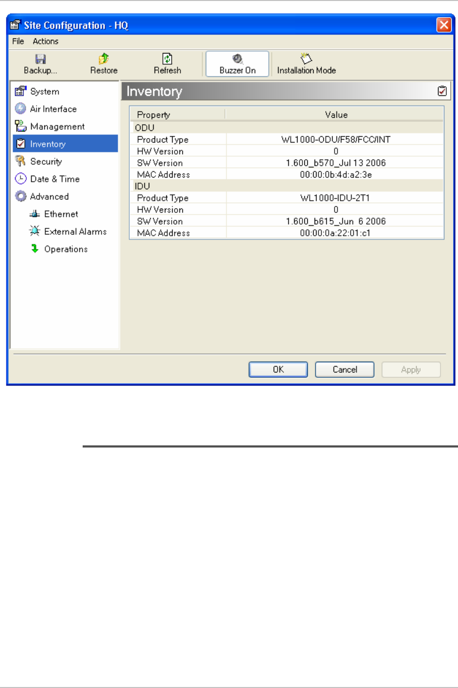
WinLink 1000 Installation and Operation Manual Chapter 4 Configuration
Figure
4-19. Inventory Screen
4.20 Configuration via Telnet
A Telnet terminal can be used to configure and monitor the ODU on
site. Remote configuration cannot be performed via Telnet.
The login password is identical to the communities' strings; Read
allows display only, Read/Write allows display and set commands.
Figure
4-20
shows the available Telnet commands.
Configuration via Telnet 4-37

Chapter 4 Configuration WinLink 1000 Installation and Operation Manual
Hello admin, welcome to ODU Management CLI!
+-----------------------------------------------------------+
Software Revision 1.700_b900_Feb 11 2007
+-----------------------------------------------------------+
admin@10.103.6.1-> help
display inventory
display management
display link
display ethernet
display tdm
display ntp
set ip <ipaddr> <subnetMask> <gateway>
set trap <index:1-10> <ipaddr> <port:0-65535>
set readpw <oldpasswd> <passwd>
set writepw <oldpasswd> <passwd>
set trappw <oldpasswd> <passwd>
set buzzer <mode:0=OFF,1 =ON>
set tpc <power:Value between minimal TX power, and maximal TX power>
set bridge <mode:0=Bridging OFF,1= Bridging ON >
reboot
help
Command "help" finished OK.
Figure
4-20. Telnet Management Screen
4-38 Configuration via Telnet