SRT Marine Systems plc SRT-MTB-OEM Class B AIS Transponder User Manual LD2103
Software Radio Technology plc Class B AIS Transponder LD2103
UserManual.wiki
>
SRT Marine Systems plc
>
SRT-MTB-OEM User Manual
>
User manual
Contents
1.
User manual
2.
Updated users manual
3.
Programming instructions
User manual
Navigation menu
Upload a User Manual
Namespaces
Wiki Guide
HTML
PDF
Info
Views
User Manual
Discussion / Help
Navigation

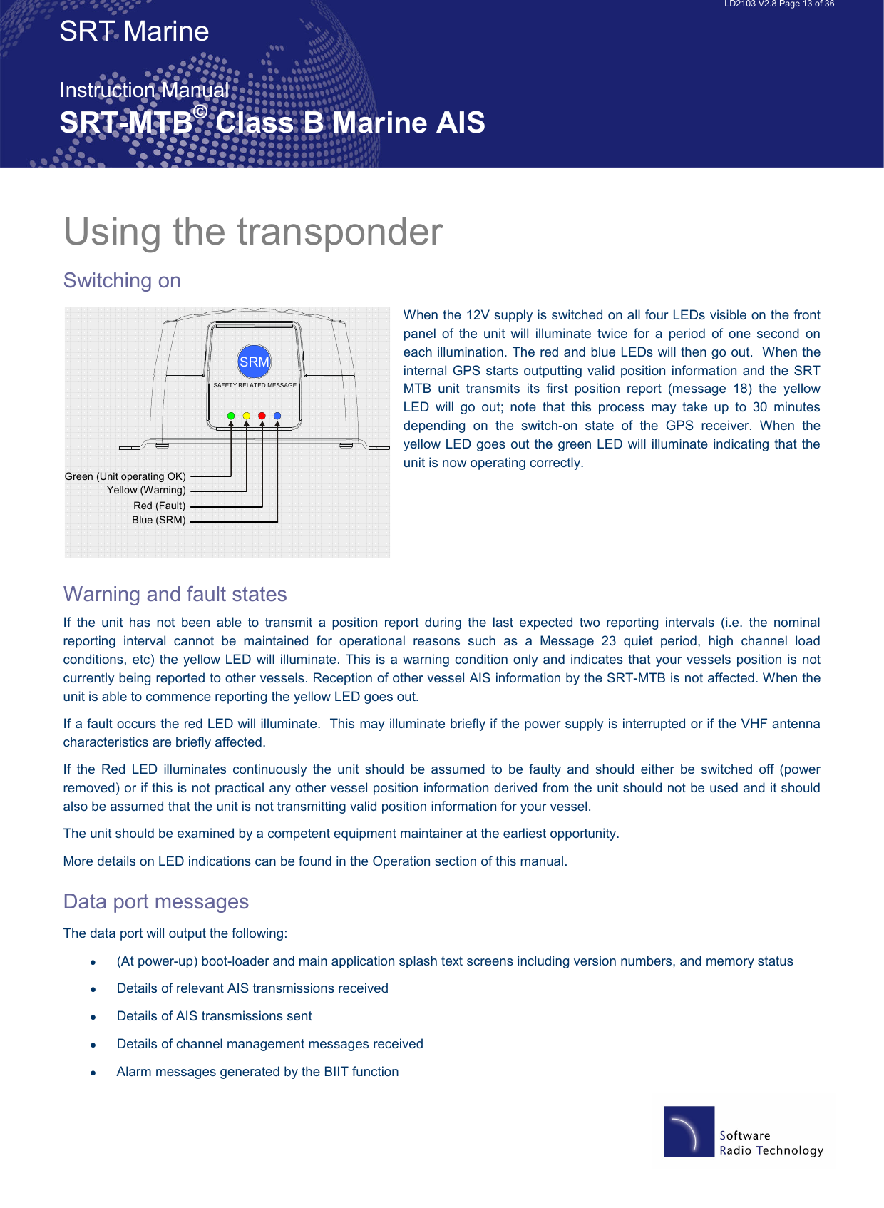
![LD2103 V2.8 Page 15 of 36 SRT Marine Instruction Manual SRT-MTB© Class B Marine AIS LED Indicators Power This is a green LED which indicates, when lit, that power has been connected correctly to the transponder, that the transponder hardware has been configured, that the operating software is present, that the CPU has booted up, the application software is running. TX Timeout This is a yellow LED which indicates when lit that the CSTDMA transmitter is prevented from transmitting. Reasons for this include the following: • The transponder’s internal GPS receiver is not operating or is not yet ready. [1] requires that a class B CSTMA transponder shall not transmit if its internal position sensor is not operating • The transponder was unable to transmit an AIS message due to the channel being already occupied, e.g. by transmissions from other AIS transponders Error This is a red LED which indicates, when lit, one of the following status conditions is possible: • Transmitter lockout timer (1 second maximum) has operated • GPS is unable to gain lock after 30 minutes • VHF antenna VSWR is out of range • Power supply is out of range • Background noise level is above the threshold level (-77dBm) SRM Status This is a blue LED which indicates when lit that the Safety Related Message (SRM) button has been depressed for more than 2 seconds and the pre-set SRM has been sent. If the SRM LED is illuminated it is not possible to send another SRM. An SRM can be sent once a second. The payload within the message 14 transmission is the text string “MAYDAY” by default. Antennas The SRT - MTB unit requires VHF and GPS antennae independent from those in use for other purposes. Please see Appendix A for details of the antennae required.](https://usermanual.wiki/SRT-Marine-Systems-plc/SRT-MTB-OEM.User-manual/User-Guide-761588-Page-15.png)