SRT Marine Systems plc SRT-MTB-OEM Class B AIS Transponder User Manual Updated users manual
Software Radio Technology plc Class B AIS Transponder Updated users manual
Contents
- 1. User manual
- 2. Updated users manual
- 3. Programming instructions
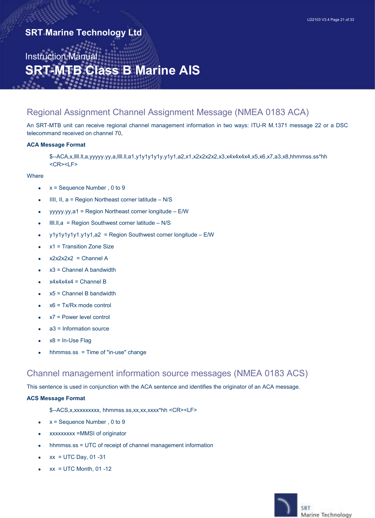
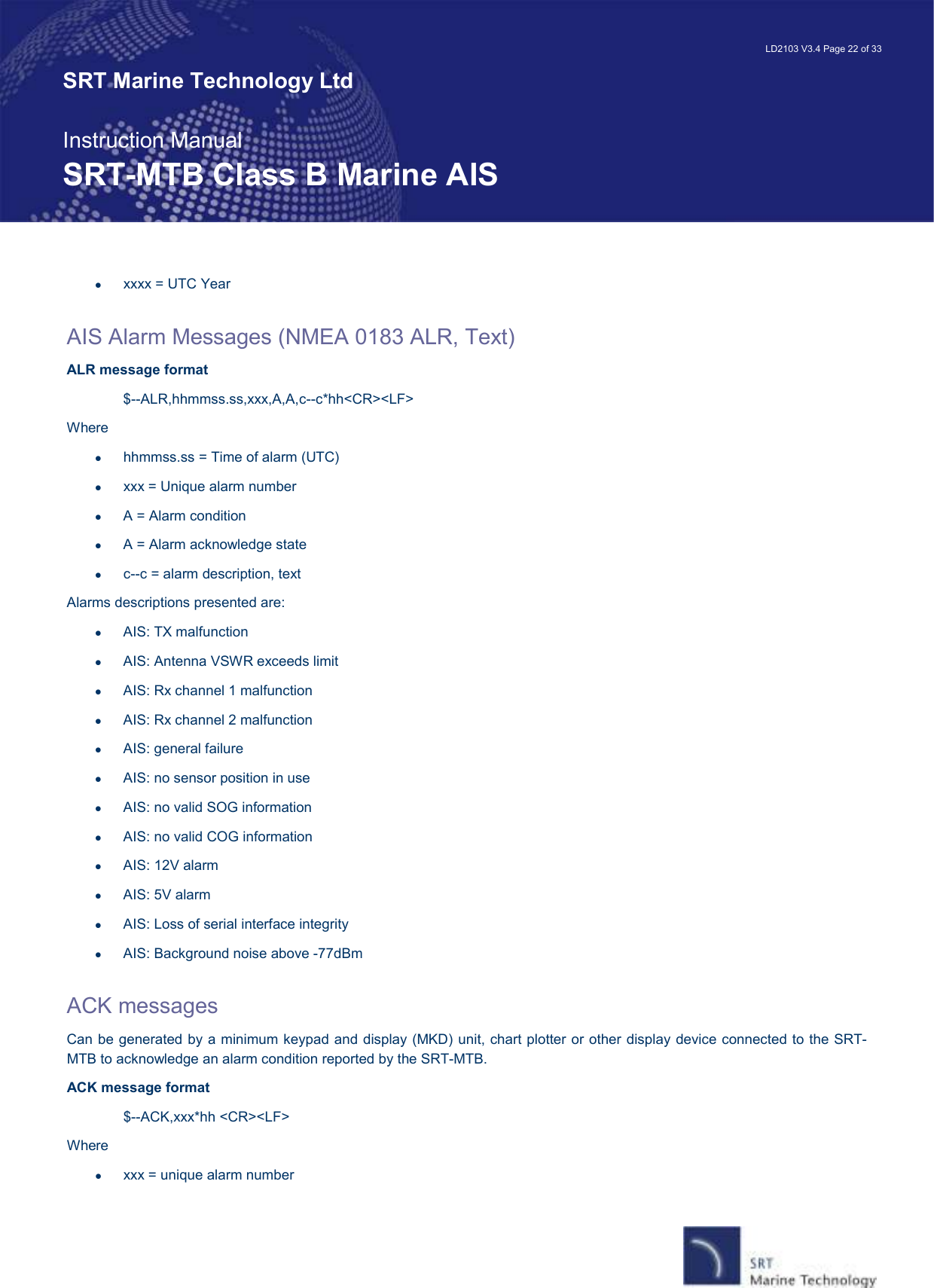
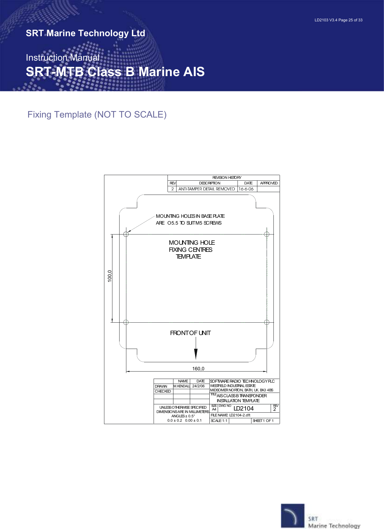
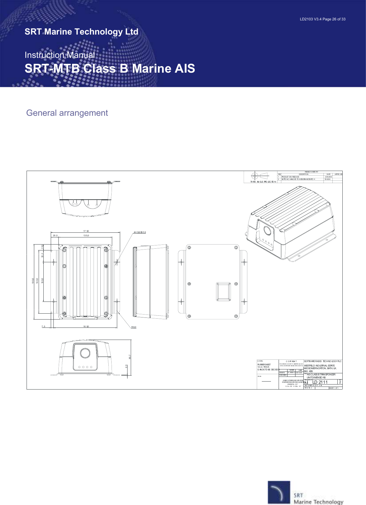
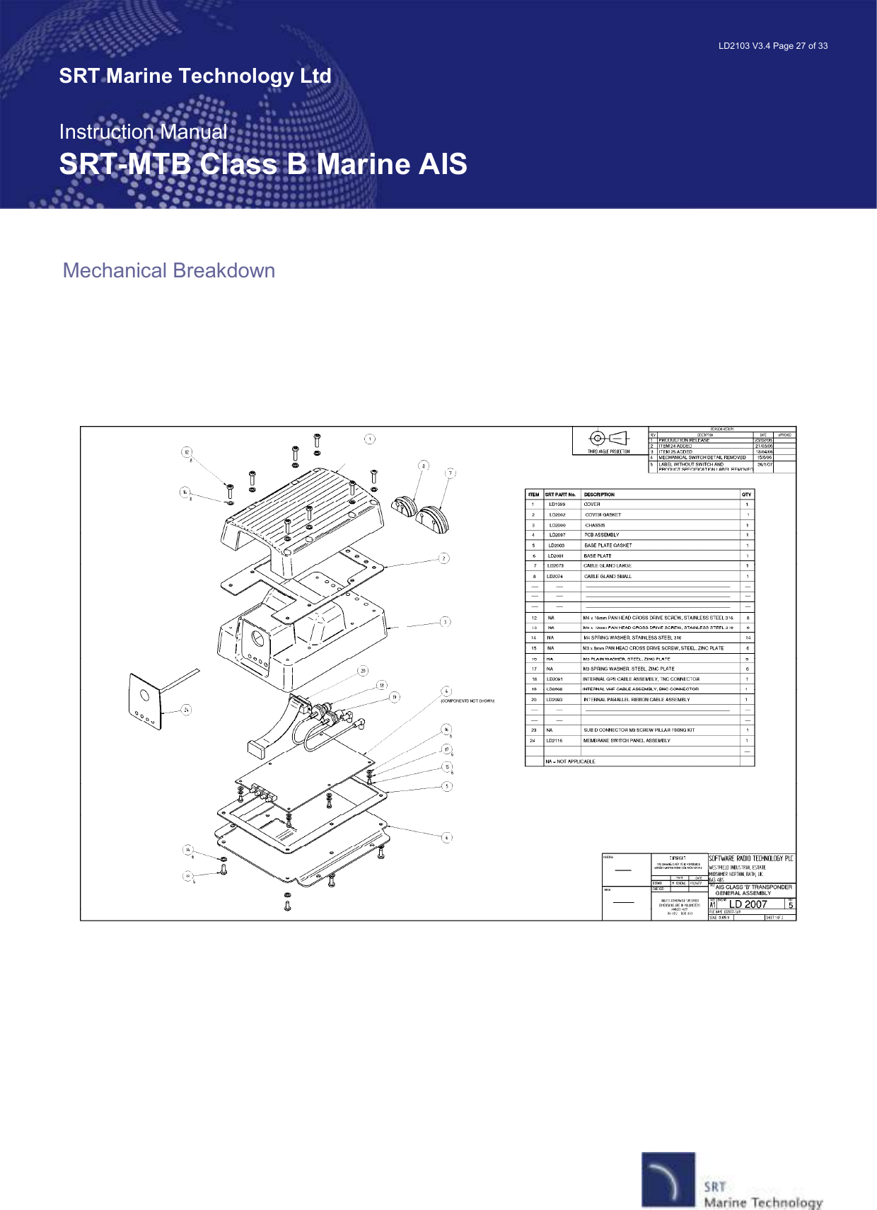
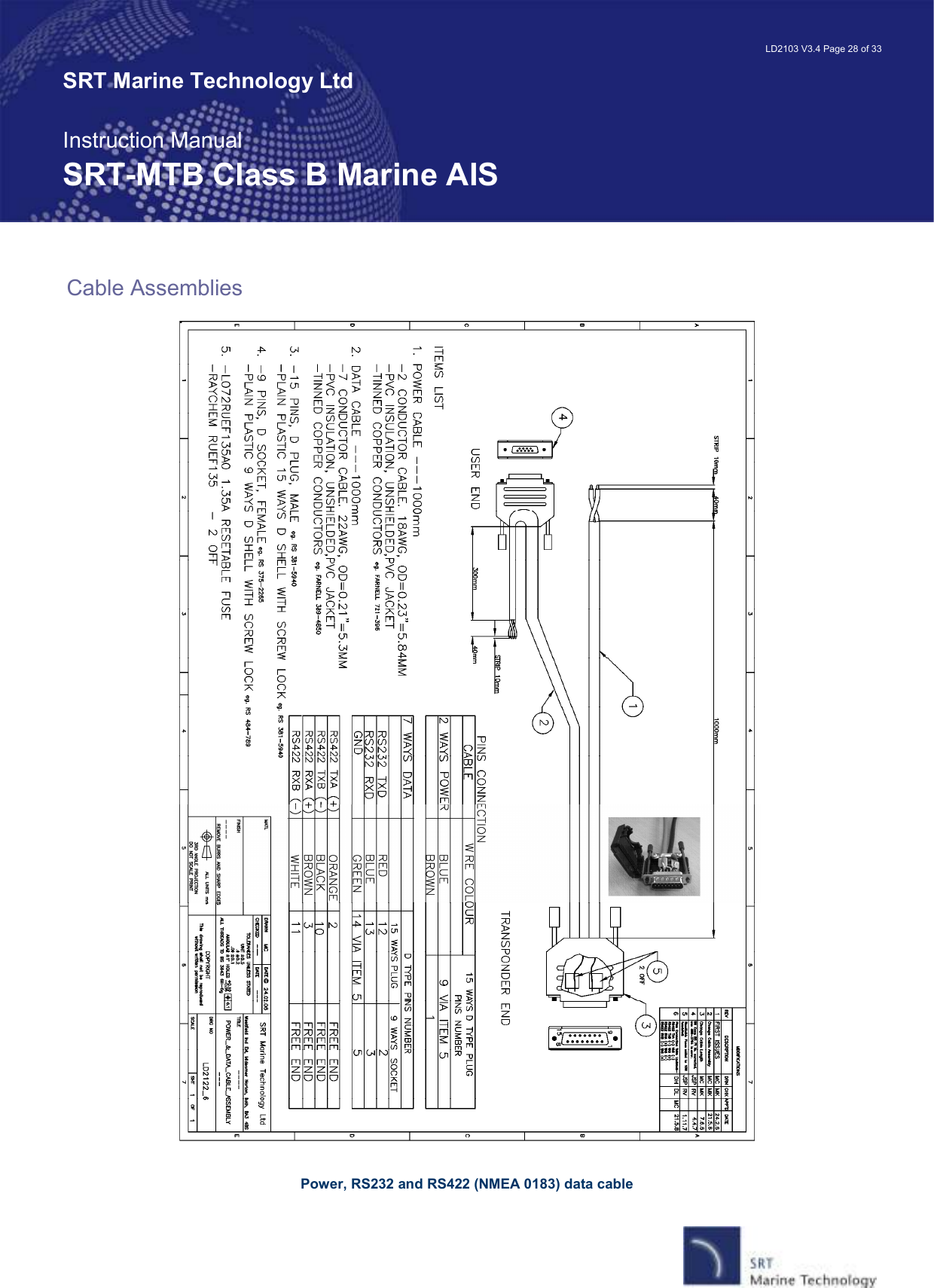
Updated users manual
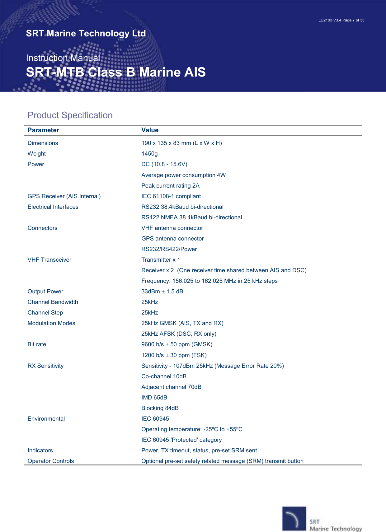
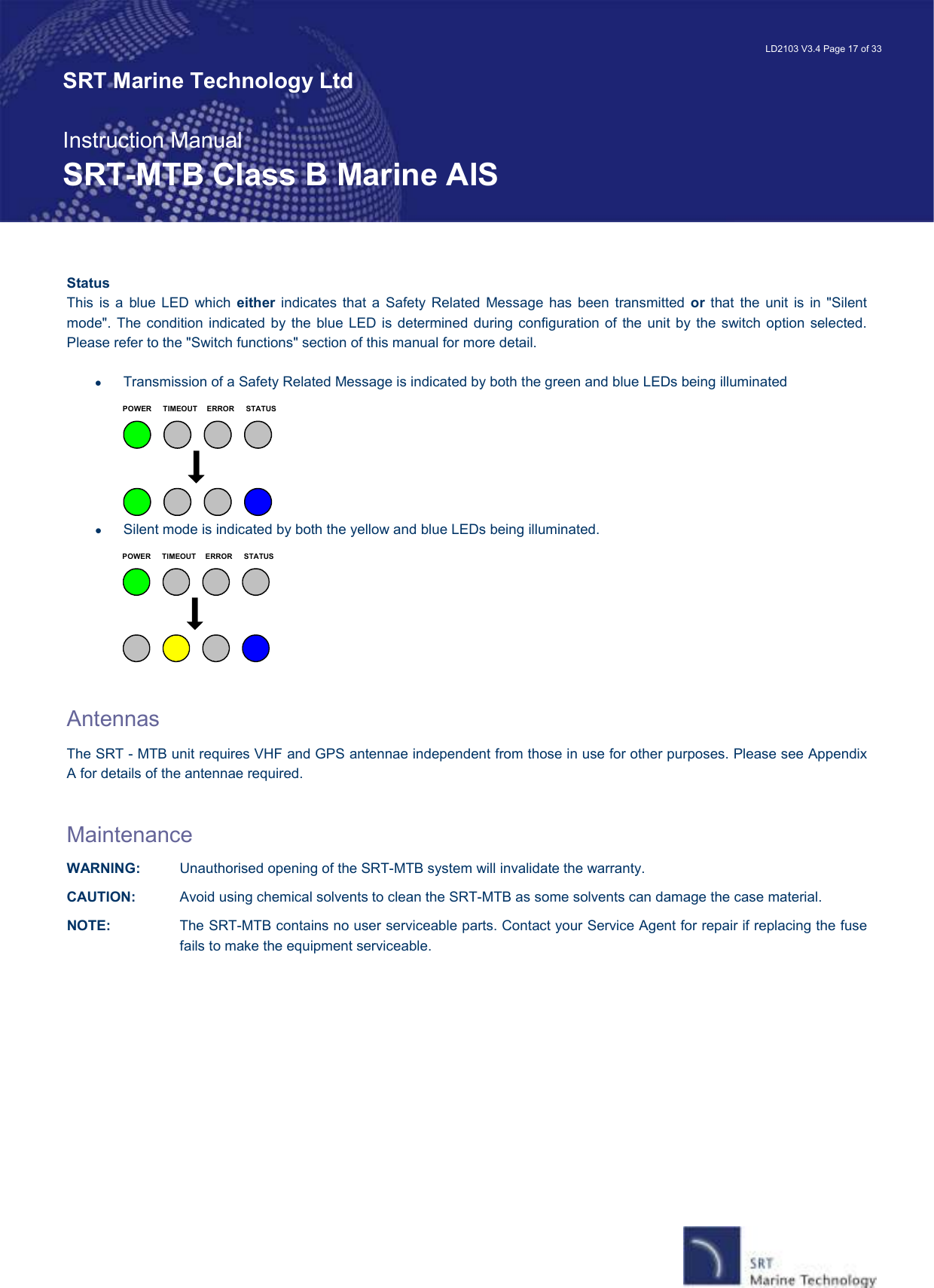
![LD2103 V3.4 Page 16 of 33 SRT Marine Technology Ltd Instruction Manual SRT-MTB Class B Marine AIS The tests include: • AIS TX malfunction (synthesiser not locked and TX time-out not exceeded) • Antenna VSWR exceeds limit • Rx channel 1 malfunction (synthesiser not locked) • Rx channel 2 malfunction (synthesiser not locked) • Internal GNSS not in use • No valid SOG information • No valid COG information • Background noise > -77dBm • GPS failure • VSWR exceeding the maximum allowed level • The input voltage is out of the specified range LED Indicators Power This is a green LED which indicates, when lit, that power has been connected correctly to the transponder, that the transponder hardware has been configured, that the operating software is present, that the CPU has booted up, the application software is running. TX Timeout This is a yellow LED which indicates when lit that the CSTDMA transmitter is prevented from transmitting. Reasons for this include the following: • The transponder’s internal GPS receiver is not operating or is not yet ready. [1] requires that a class B CSTMA transponder shall not transmit if its internal position sensor is not operating • The transponder was unable to transmit an AIS message due to the channel being already occupied, e.g. by transmissions from other AIS transponders • The transponder is in "Silent mode" Error This is a red LED which indicates, when lit, one of the following status conditions is possible: • Transmitter lockout timer (1 second maximum) has operated • GPS is unable to gain lock after 30 minutes • VHF antenna VSWR is out of range • Power supply is out of range • Background noise level is above the threshold level (-77dBm)](https://usermanual.wiki/SRT-Marine-Systems-plc/SRT-MTB-OEM.Updated-users-manual/User-Guide-1008800-Page-16.png)