Saab TransponderTech R5-AIS R5 AIS Transponder User Manual manual
Saab TransponderTech AB R5 AIS Transponder manual
Contents
- 1. manual
- 2. Manual
manual

OPERATION & INSTALLATION MANUAL
Saab TransponderTech
R5
SOLID AIS
System
This page is intentionally empty

R5 SOLID AIS System
THE AUTOMATIC IDENTIFICATION SYSTEM
7000 118-200, A4 Page 3
i Copyright
The entire contents of this manual and its appendices, including
any future updates and modifications, shall remain the property
of Saab TransponderTech AB at all times. The contents must
not, whether in its original form or modified, be wholly or partly
copied or reproduced, nor used for any other purpose than the
subject of this manual.
Saab TransponderTech AB, SWEDEN
ii Disclaimer
While reasonable care has been exercised in the preparation of
this manual, Saab TransponderTech AB shall incur no liability
whatsoever based on the contents or lack of contents in the
manual.
iii Software
This manual reflects the capabilities of the R5 SOLID AIS
System with Software 1.0.1. If the system since delivery has
been updated from this version, such change should be
reflected on a label on the unit. Current software version can
always be verified in the S/W info dialog as described in 4.23.
iv Manual Part Number and Revision
Part number 7000 118-200, revision A4.
v Safety Instructions
Note the following compass safe distances:
Equipment
Standard magnetic
compass
Steering magnetic
compass
R5 SOLID Transponder
0.60 m
0.45 m
GPS Antenna AT575-68
0.30 m
0.30 m
GPS Antenna MA-700
0.65 m
0.50 m
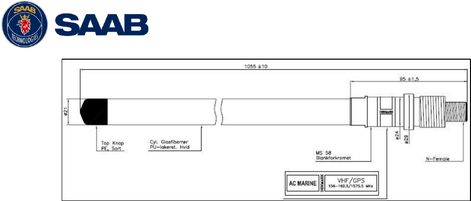
Combined VHF/GPS
0.65 m
0.50 m
vi Disposal Instructions
Broken or unwanted electrical or electronic equipment parts
shall be classified and handled as „Electronic Waste‟. Improper
disposal may be harmful to the environment and human health.

R5 SOLID AIS System
THE AUTOMATIC IDENTIFICATION SYSTEM
7000 118-200, A4 Page 4
Please refer to your local waste authority for information on
return and collection systems in your area.
vii Contact Information
For installation, service, ordering info and technical support
please contact your local Saab TransponderTech
representative. A list of dealers and service stations can be
found on the corresponding product page at
www.saabgroup.com/transpondertech.

R5 SOLID AIS System
THE AUTOMATIC IDENTIFICATION SYSTEM
7000 118-200, A4 Page 5
TABLE OF CONTENTS
1 The Automatic Identification System ........................................... 8
2 System Overview ........................................................................... 9
2.1 Product Description ............................................................................................... 9
2.2 Main features ........................................................................................................ 10
3 Installation .................................................................................... 11
3.1 Unpacking the Equipment .................................................................................... 11
3.2 Installation Cables ................................................................................................ 12
3.3 Installation procedure .......................................................................................... 12
3.4 Mount the R5 SOLID ............................................................................................. 13
3.5 Mount the R5 SOLID transponder’s VHF antenna .............................................. 17
3.6 Mount the R5 SOLID GPS antenna ...................................................................... 19
3.7 Electrical Installation ............................................................................................ 21
3.8 System Configuration ........................................................................................... 26
4 Operation ...................................................................................... 27
4.1 System Mode ........................................................................................................ 27
4.2 LED’s and Controls .............................................................................................. 27
4.3 Main Menu – Tree View ......................................................................................... 30
4.4 Configuration Parameters .................................................................................... 31
4.5 Alarm and Alert Pop-ups ...................................................................................... 40
4.6 Status Bar.............................................................................................................. 40
4.7 Status Icons .......................................................................................................... 41
4.8 View Remote Ship Information ............................................................................ 42
4.9 View Plot of Targets ............................................................................................. 42
4.10 View Transmitted Own Ship Information ............................................................ 43
4.11 Enter and Read Voyage Related Information ...................................................... 43
4.12 Handling Safety Related Messages (SRM) and Text Messages......................... 44
4.13 Send Persons On Board ....................................................................................... 45
4.14 Long Range Interrogations .................................................................................. 46
4.15 Inland ETA and RTA ............................................................................................. 47
4.16 Inland Water Levels .............................................................................................. 47
4.17 Regional Areas...................................................................................................... 47
4.18 Alarms ................................................................................................................... 48
4.19 Status List ............................................................................................................. 48
4.20 Non Functional Time ............................................................................................ 49

R5 SOLID AIS System
THE AUTOMATIC IDENTIFICATION SYSTEM
7000 118-200, A4 Page 6
4.21 GPS Status ............................................................................................................ 49
4.22 View Raw Data ...................................................................................................... 49
4.23 SW/HW Info ........................................................................................................... 50
4.24 VHF Status ............................................................................................................ 50
4.25 Communication Test ............................................................................................ 50
4.26 Update Software ................................................................................................... 51
4.1 Restore Config ...................................................................................................... 51
5 Software Upgrade ........................................................................ 52
6 Technincal Specifications ........................................................... 53
6.1 Physical ................................................................................................................. 53
6.2 Electrical ............................................................................................................... 53
6.3 Environmental ....................................................................................................... 53
6.4 VHF Transceiver ................................................................................................... 53
6.5 Internal GPS Receiver .......................................................................................... 54
6.6 AIS Alarm Relay .................................................................................................... 54
7 Troubleshooting ........................................................................... 55
7.1 Troubleshooting prerequisites ............................................................................ 55
7.2 Troubleshooting with the front panel LED’s ....................................................... 55
7.3 Troubleshooting with alarm messages ............................................................... 56
7.4 Troubleshooting via the display .......................................................................... 58
7.5 Reporting intervals for Class A transponders .................................................... 60
7.6 F.A.Q ...................................................................................................................... 61
7.7 Contacting Support .............................................................................................. 61
7.8 Indication Messages ............................................................................................. 62
7.9 Long Range Definitions ........................................................................................ 62
8 Interpretation of Input Sentences ............................................... 63
8.1 GPS and Sensor Input Sentences ....................................................................... 63
8.2 General Input Sentences ...................................................................................... 67
8.3 AIS Specific Input Sentences ............................................................................... 67
8.4 Long range input sentences ................................................................................ 70
8.5 Proprietary Input Sentences ................................................................................ 70
9 Interpretation of Output Sentences ............................................ 71
9.1 Proprietary Output Sentences (PSTT) ................................................................. 71
9.2 Long range output sentences .............................................................................. 72
9.3 AIS output sentences ........................................................................................... 74

R5 SOLID AIS System
THE AUTOMATIC IDENTIFICATION SYSTEM
7000 118-200, A4 Page 7
10 Glossary ....................................................................................... 78
10.1 Units ...................................................................................................................... 80
11 Appendix A - License ................................................................... 81
11.1 Copy of the GNU General Public License ........................................................... 81

R5 SOLID AIS System
THE AUTOMATIC IDENTIFICATION SYSTEM
7000 118-200, A4 Page 8
1 THE AUTOMATIC IDENTIFICATION SYSTEM
The Automatic Identification System (AIS) is a safety information system that was
proposed as a worldwide standard in 1997 and adopted by IMO in 1998. The AIS system
is standardized by ITU, IEC, IALA and IMO and is subject to approval by a certification
body. The first type approved AIS transponder in the world was Saab TransponderTech‟s
R3 Class A Transponder in 2002.
AIS allows transceivers to automatically share static and dynamic data such as ship
name, call sign, dimensions, position and sensor information on two dedicated data links
in the upper marine VHF band. There are a number of different AIS devices that can send
and receive information on the AIS data link:
Class A Transponder – This type of transponder is used on open sea waters and
is mandatory for ships of 300 gross tonnage or more on international voyages, all
cargo ships of 500 gross tonnage or more and on passenger ships.
Class B Transponder – Used on smaller vessels and pleasure crafts. It transmits
with a lower power than the class A transponder and has lower priority on the data
link.
Base Station – Fixed shore station that is typically connected to an AIS network to
collect information from all vessels at a certain port or shore line.
Repeater Stations – Used to extend coverage range by repeating incoming
messages. Can be implemented as a function in an AIS Base station or an AtoN
station
SAR (Search and Rescue) Transponder – Used on airplanes and helicopters in
search and rescue missions.
AtoN (Aids to Navigation) – A transceiver that is fitted on buoys and lighthouses
in order to send information about their positions.
Inland AIS – An European standardized extension to Class A systems for use on
inland water ways. An inland transponder has additional messages to
communicate with bridges, ports and locks and can also send some additional
information that are useful on water ways such as blue sign indication, specific
hazardous cargo etc.
SART (Search and Rescue Transmitters) – Distress beacons for life rafts. An
active SART unit will always be sorted on top of the target list in the R5 SOLID to
accentuate its presence.
NOTE:
The R5 SOLID AIS SYSTEM can be operated in either Class A or Inland modes
depending on user need.
R5 SOLID AIS System
SYSTEM OVERVIEW
7000 118-200, A4 Page 9
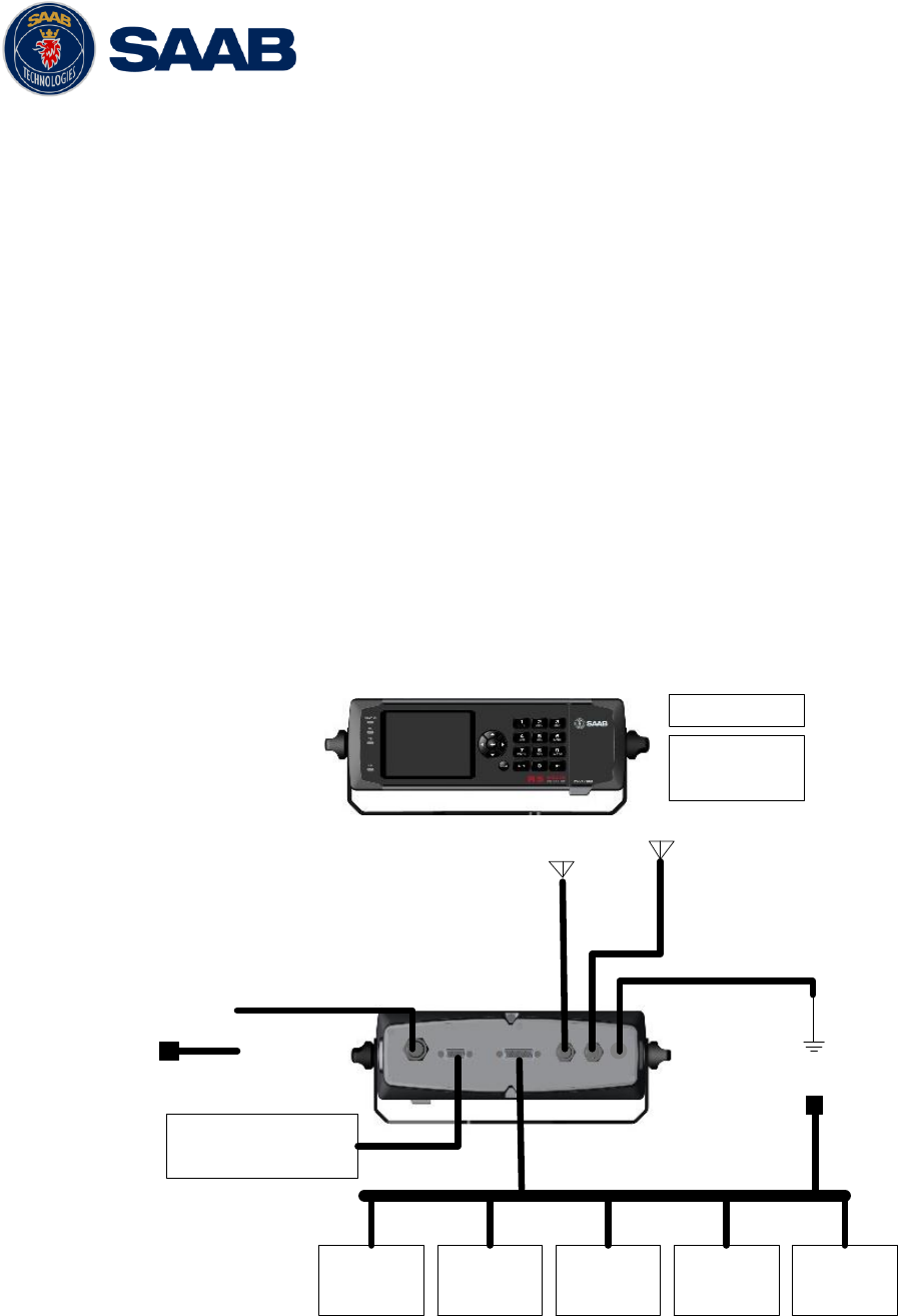
2 SYSTEM OVERVIEW
2.1 Product Description
The R5 SOLID AIS System (R5 SOLID from here on) consists of a transceiver radio unit,
a GPS receiver, a controller unit and a colour LCD with a numerical keypad. The radio has
three receivers, two tuneable TDMA receivers and one DSC receiver. The transmitter
alternates its transmissions between the two operating TDMA). The controller unit creates
and schedules data packets (containing dynamic, static and voyage related data) for
transmission based on the IMO performance standard for AIS.
The R5 SOLID shall be connected to the ship‟s sensors as required by the installation
guidelines published by IALA. The R5 SOLID can interface external navigation and
presentation systems that support required IEC 61162-1 sentences. Refer to chapter 8
“Interpretation of Input Sentences” for more information. The R5 SOLID is prepared for
connection to Long Range systems like Inmarsat C.
The colour LCD and numerical keypad provides a graphical user-friendly interface to the
system. It is possible to plot the location of other vessels, aids to navigation and search
and rescue vessels. The LCD and numerical keypad can also be used to send and
receive messages, perform configuration as well as supervise the systems status.
Pilot Plug
USB Host
Interface
ECDIS
ARPA Long
Range Sensor
1Sensor
2Sensor
3
RS-232
(ECDIS/GNSS)
Alarm
Relay
24 VDC
External fuse
External
Switch
VHF
GPS
RS-422 Ports
GND
Figure 1 - System Overview

R5 SOLID AIS System
SYSTEM OVERVIEW
7000 118-200, A4 Page 10
2.2 Main features
Multi colour 3,5” LCD with numerical keypad interface
USB Host interface for connection of USB keyboard and USB flash memories.
Individual visual display settings for day and night operations.
Broadcast of Dynamic, Static and Voyage related information.
Standardized interface for connection to ship sensors e.g. GNSS, Gyro, Rate of
Turn Indicator, ECDIS/ECS and ARPA.
Plot capable of presenting up to 500 targets in the vicinity of the own ship.
Messaging views for generation and presentation of safety related messages and
text messages.
Mandatory pilot plug integrated to the front of the transponder unit.
Channel management capability for areas without access to the worldwide
allocated AIS frequencies.
Possibility to generate Long Range AIS reply over satcom equipment such as
Inmarsat C.
In addition to the normal high (12,5W) and low (1W) power mode, the R5 SOLID
has a 1W tanker mode in accordance with requirements for tanker operations in
port.
Reception and processing of AIS messages 18,19 and 24A/B as transmitted by
AIS Class B „CS‟ Transponders.
Easily upgraded with the latest software release from Saab using USB memory

R5 SOLID AIS System
INSTALLATION
7000 118-200, A4 Page 11
3 INSTALLATION
3.1 Unpacking the Equipment
The R5 SOLID AIS System typically consists of the following parts:
Name
Part number
Qty.
R5 SOLID AIS Transponder
SOLAS Class A & Inland AIS
7000 118-501
1
R5 Power Cable 2m
7000 118-077
1
R5 Signal Cable DSUB-Open 2m
7000 118-078
1
R5 SOLID System Delivery CD
Including
Installation & Operator Manual
7000 118-331
7000 118-200
1
R5 SOLID Printed Doc Set
Including
Installation short instruction
Operator short instruction
Certificate set
7000 118-330
7000 118-201
7000 118-202
7000 118-203
1
Table 1 – R5 SOLID Basic Equipment
Name
Part number
GPS antenna options
MA-700
AT575-68
Combined VHF/GPS Antenna AC Marine
7000 000-485
7000 000-135
7000 000-435
Stainless Steel Antenna Mount 1" x 14
7000 000-472
AIS Alarm Relay Unit incl. socket
7000 100-132
R5 SOLID Upgrade CD
7000 118-332
VHF Antenna BA1012
7000 000-077
USB to Pilot plug cable/converter
7000 108-328
Table 2 – Accessories (Optional)

R5 SOLID AIS System
INSTALLATION
7000 118-200, A4 Page 12
3.2 Installation Cables
The following cables are needed to install the R5 SOLID.
R5 Signal Cable, DSUB-Open
Type: Shielded Twisted Pair x 0.33 mm2
Length: 2 m
Connector: 26-pole H.D.D-SUB (female)
Marking: 7000 118-078, A
R5 Power Cable
Type: Unshielded 4 wire cable x 1.3 mm2
Length: 2 m
Connector: ConXall Mini-Con-X 6382-4SG-311 (female)
Marking: 7000 118-077, A
R5 SOLID VHF antenna cable
Type and length: See Section 3.5.2 VHF Cabling
Connector: BNC (Male)
R5 SOLID GPS Antenna Cable
The standard GPS antenna MA-700 for the R5 SOLID transponder system is
prewired with an antenna cable. For other GPS antennas an extern GPS
antenna cable is needed.
Type and Length: See Section 3.6.2 GPS Cabling
Connector: TNC (Male)
3.3 Installation procedure
When installing the R5 SOLID, it is recommended to follow the steps described in this
Installation Manual. Details of the installation procedure can be found in the coming
sections of the Installation Manual.
Recommended installation steps:
1. Mount the R5 SOLID at conning station
2. Mount the alarm relay unit
3. Mount the VHF antenna
4. Mount the GPS antenna
5. Connect all external systems and sensors to the R5 SOLID
6. Power up the system
7. Set configuration parameters
8. Perform system functional check

R5 SOLID AIS System
INSTALLATION
7000 118-200, A4 Page 13
3.3.1 Equipment installation environment
The table below lists the IEC 60945 equipment classification for the system.
Name
Part number
IEC 60945
installation category
R5 SOLID Class A / Inland AIS unit
7000 118-501
Protected
MA-700
AT575-68
VHF/GPS Antenna:
VHF/GPS Antenna element
VHF/GPS diplexer
7000 000-485
7000 000-135
7000 000-435
Exposed
Exposed
Exposed
Protected
Table 3 – Equipment installation environment
3.4 Mount the R5 SOLID
3.4.1 Location
The R5 SOLID should be mounted close to the position from which the ship is normally
operated, preferably on the bridge console close to the conning position.
When mounting the R5 SOLID, please consider the following:
The R5 SOLID shall be connected to ship ground using the earth terminal found
on the rear plate.
The temperature and humidity should be moderate and stable at the place of
mounting, +15ºC to +35ºC (Operating temperature: -15ºC to +55ºC.)
Select a location away from excessive heat sources
Ensure that there is enough airflow to avoid high ambient temperatures
Avoid areas where there is a high flow of humid salt air
Avoid places with high levels of vibrations and shocks
Avoid mounting the R5 SOLID in direct sunlight for the best readability
Ensure that the cables can be connected without violating their maximum
bending radius
The unit can affect magnetic compasses. The minimum compass safe distance
is 0.60 meters to a standard magnetic compass and 0.45 meters to a steering
magnetic compass
R5 SOLID AIS System
INSTALLATION
7000 118-200, A4 Page 14
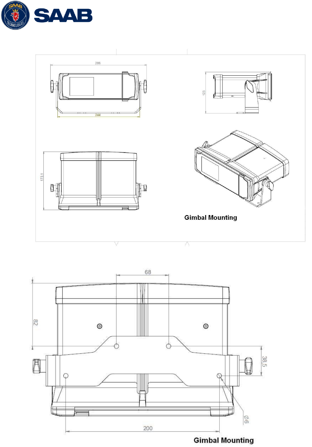
3.4.2 Physical Size and Mechanical Drawing
Figure 2 – Gimbal Mount
Figure 3 – Gimbal Mount (Bottom View)
R5 SOLID AIS System
INSTALLATION
7000 118-200, A4 Page 15
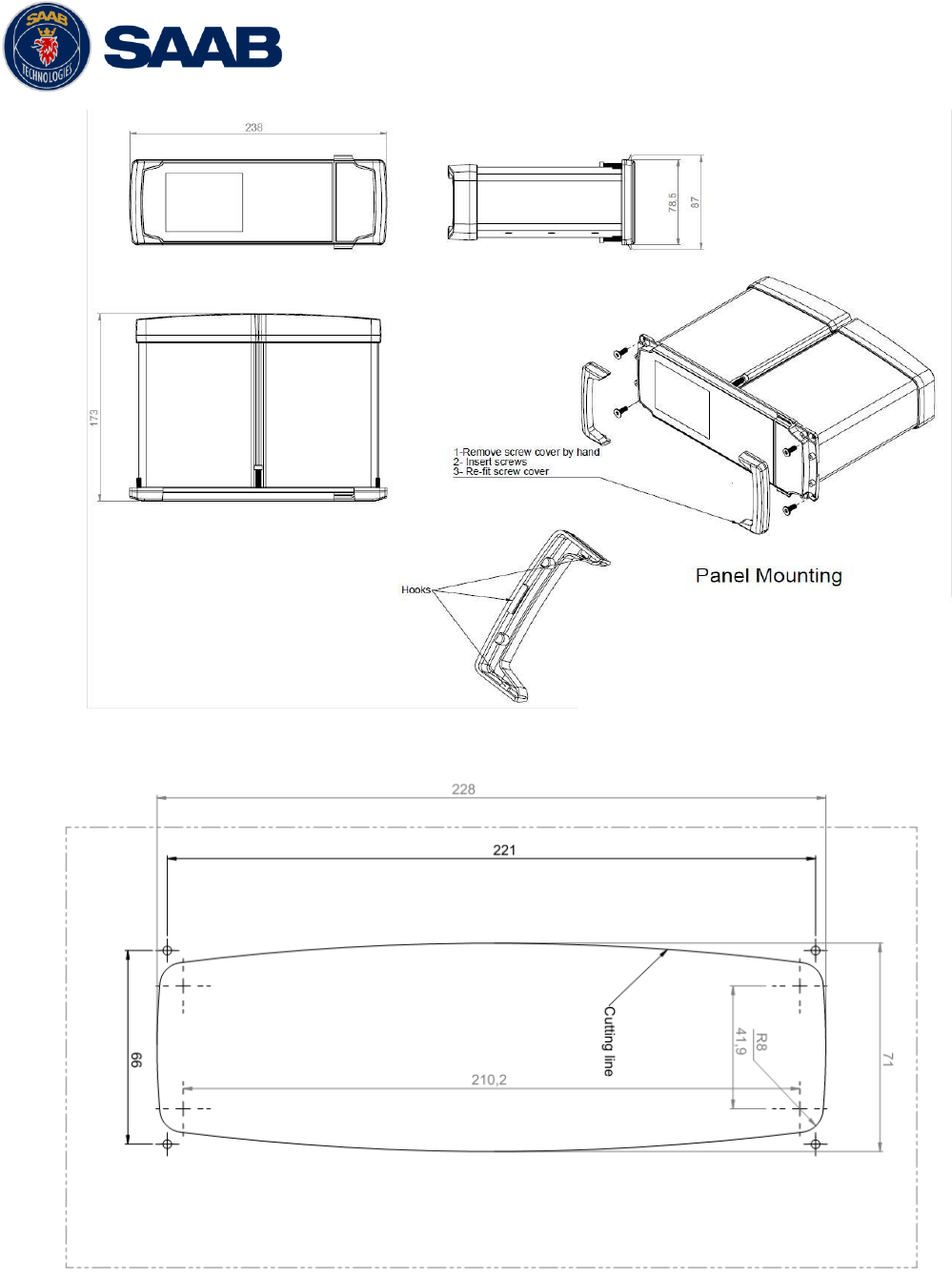
Figure 4 – Panel Mount
Figure 5 – Panel Mount Front View
R5 SOLID AIS System
INSTALLATION
7000 118-200, A4 Page 16
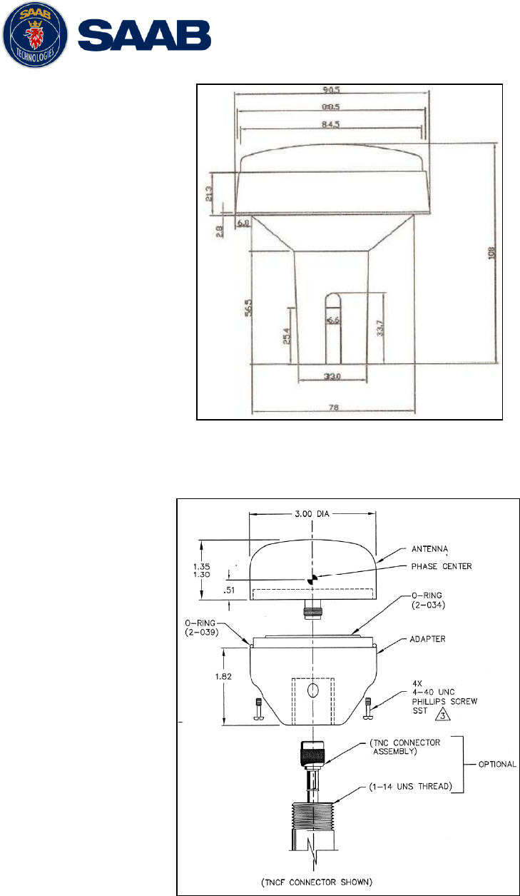
Figure 6 – GPS Antenna – MA-700
Figure 7 – GPS Antenna – AT575-68
R5 SOLID AIS System
INSTALLATION
7000 118-200, A4 Page 17
Figure 8 – Combined VHF / GPS Antenna – AC Marine
3.5 Mount the R5 SOLID transponder’s VHF antenna
The R5 SOLID, like any other ship borne transceiver operating in the VHF maritime band,
may cause interference to a ship‟s VHF radiotelephone. Because AIS is a digital system,
this interference may occur as a periodic (e.g. every 10 second) soft clicking sound on a
ship‟s radiotelephone. This effect may become more noticeable when the VHF
radiotelephone antenna is located close to the AIS VHF antenna and when the
radiotelephone is operating on channels near the AIS operating channels (e.g. channels
27, 28 and 86).
Attention should be paid to the location and installation of different antennas in order to
obtain the best possible efficiency. Special attention should be paid to the installation of
mandatory antennas like the AIS antennas.
So, installing the AIS VHF antenna is also a crucial part of the system installation. How
and where you install your AIS VHF antenna and cable will affect its efficiency.
3.5.1 VHF Antenna Location
Location of the mandatory AIS VHF antenna should be carefully considered. Digital
communication is more sensitive than analogue/voice communication to interference
created by reflections in obstructions like masts and booms. It may be necessary to
relocate the VHF radiotelephone antenna to minimize the interference effects. Installing
the VHF antenna for AIS on a vessel is a compromise between the following items:
Antenna type
Antenna separation
Clear view of the horizon
Antenna height
3.5.1.1 Antenna type
The AIS VHF antenna should have Omni directional vertical polarization providing unity
gain.
3.5.1.2 Antenna separation
The AIS transponders are using simplex channels at frequencies on the high side of
the marine mobile band (AIS channel A = 2087 (161.975 MHz) and AIS channel B =
2088 (162.025 MHz)). These channels are close to the duplex channels used for shore
to ship marine communication. The AIS VHF antenna should be separated as much as

R5 SOLID AIS System
INSTALLATION
7000 118-200, A4 Page 18
possible from the voice VHF installations used for main communication to avoid
unnecessary interference.
There should not be more than one antenna on the same level. The AIS VHF
antenna should be mounted directly above or below the ship‟s primary VHF
radiotelephone antenna, with no horizontal separation and with a minimum of 2 meters
vertical separation. If it is located on the same level as other antennas, the distance
apart should be at least 10 meters.
The AIS VHF antenna should be installed safely away from interfering high-power
radiating sources like radar and other transmitting radio antennas, preferably at least 3
meters away from and out of the transmitting beam.
3.5.1.3 Clear view of the horizon
The AIS VHF antenna should be placed in an elevated position that is as free as
possible with a minimum distance of 2 meters in horizontal direction from constructions
made of conductive materials. The antenna should not be installed close to any large
vertical obstruction. The objective for the AIS VHF antenna is to see the horizon freely
through 360 degrees.
3.5.1.4 VHF Antenna height
The AIS is using VHF radio frequencies, which propagation characteristics are close to
line of sight. The higher the antenna location is, the longer the range will be.
3.5.2 VHF Cabling
The cable should be kept as short as possible to minimize attenuation of the signal.
Double shielded coaxial cable equal or better than RG214 is recommended to minimize
the effects from electromagnetic interference from high power lines, radar or other
radio transmitter cables.
The table below gives recommendation on cables that can be used for the VHF-
antenna connections, the cables used should always be of marine approved type. The
cable attenuation shall be kept as low as possible, a 3 dB loss is the same as a
reduction of the input and output signal to a half.
Table 4 – VHF Antenna cables
Ex: A cable of 40 meter RG 214 has a cable attenuation of 2.8 dB.
3.5.3 VHF Cable mounting
Coaxial cables should be installed in separate signal cable channels/tubes and at least
10 cm away from power supply cables. Crossing of cables should be done at right
angles (90°).
Type
Attenuation @ 150
MHz (dB/100m)
(mm)
Weight (kg/100m)
RG 214
7
10.8
18.5
RG 217
5
13.8
30.1
RG 225
8
10.9
23.3

R5 SOLID AIS System
INSTALLATION
7000 118-200, A4 Page 19
Coaxial cables should not be exposed to sharp bends, which may lead to a change of
the characteristic impedance of the cable. The minimum bending radius should be 5
times the cable's diameter.
All outdoor installed connectors should be weather proofed, e.g. with shrink tubing,
watertight seal tape or butyl rubber tape and plastic tape sealing, to protect against
water penetration into the antenna cable.
Secure the cable properly, close to the cable ends.
3.5.4 VHF Cable Grounding
Coaxial down-leads must be grounded. The coaxial shielding screen should be
connected to ground at one end.
3.6 Mount the R5 SOLID GPS antenna
The R5 SOLID shall be connected to a GPS antenna type MA-700, AT575-68 or a
combined AC Marine GPS/VHF antenna. 5V DC is supplied through the antenna lead for
the antenna preamplifier.
Please note the Compass Safe Distances in section 6.3 Environmental.
The diplexer for the combined AC Marine GPS/VHF antenna unit shall be installed in an
indoor environment.
Attention should be paid to the location and installation of the different antennas on the
ship in order to obtain the best possible efficiency. Special attention should be paid to the
installation of mandatory antennas like the AIS antennas.
So, installation of the GPS antenna is a crucial part of the system installation. How and
where you install your GPS antenna and cable will greatly affect its sensing efficiency.
3.6.1 GPS Antenna location
The GPS antenna must be installed where it has a clear view of the sky. The objective
is to see the horizon freely through 360 degrees with a vertical observation of 5 to 90
degrees above the horizon. Small diameter obstructions, such as masts and booms, do
not seriously degrade signal reception, but such objects should not eclipse more than a
few degrees of any given bearing. Do not mount the antenna in the top of a mast or
tower, as this may degrade the COG and SOG readings.
Locate the GPS antenna at least 3 meters away from and out of the transmitting beam
of high-power transmitters such as S-Band Radar (typically 15° vertically from the
array‟s centre point) and/or Inmarsat systems (A, B, C, or M; typically 10º from the
array‟s centre point in any of the possible transmitting directions).
Locate the GPS antenna at least 3 meters away of a HF or VHF radios or their
antennas. This includes the ship‟s own AIS VHF antenna if it is designed and installed
separately.
3.6.2 GPS Cabling
The gain of the GPS antenna built-in pre-amplifier shall match the cable attenuation.
The resulting installation gain (pre-amplifier gain - cable attenuation) shall be within 0 to
26 dB. A minimum value of 10 dB is recommended for optimum performance.
Double shielded coaxial cable is recommended. The coaxial cable should be routed
directly between the GPS antenna and the R5 SOLID GPS connector in order to
reduce electromagnetic interference effects. The cable should not be installed close to
high-power lines, such as radar or radio transmitter lines or the AIS VHF antenna
R5 SOLID AIS System
INSTALLATION
7000 118-200, A4 Page 20
cable. A separation of 1 meter or more is recommended to avoid interference due to
RF-coupling. Crossing of antenna cables should be done at 90 degrees to minimise
magnetic field coupling.
The table below gives recommendation on cables that can be used for the
Transponder GPS-antenna connections, the cables used should always be of marine
approved type. Due to the high frequency it‟s important that the attenuation in the cable
is low for the specific frequency (1.5 GHz).
Type
Attenuation @ 1.5
GHz (dB/m)
(mm)
Weight (kg/100m)
RG 58
0.9
5
3.7
RG 400
0.6
4.95
6.3
RG 223
0.6
5.40
5.5
RG 214
0.35
10.8
18.5
RG 225
0.3
10.9
23.3
Table 5 – GPS Antenna Cables
For optimum performance of the transponder approximately +10dB gain should be
available when the cable attenuation has been subtracted from the GPS-antenna
preamplifier gain. The net gain shall not exceed +26dB.
Example:
Cable type
Preamplifier
Gain (dB)
Required min cable
length (m)
Recommended
max. cable length
(m)
RG 58
12
0
2
RG 58
26
0
18
RG 58
30
4.5
22
RG 223
12
0
3.5
RG 223
26
0
26.5
RG 223
30
6.5
33.5
RG 214
12
0
6
RG 214
26
0
46
RG 214
30
11.5
57
Table 6 – GPS Antenna Cables - Example

R5 SOLID AIS System
INSTALLATION
7000 118-200, A4 Page 21
Min length = (Preamp. Gain – 26 dB)/Cable attenuation per meter
Max length = (Preamp. Gain – 10 dB)/Cable attenuation per meter
3.6.3 GPS Cable mounting
Coaxial cables (marine approved type) should be installed in separate signal cable
channels/tubes and at least 10 cm away from power supply cables. Crossing of cables
should be done at right angles (90°).
Coaxial cables should not be exposed to sharp bends, which may lead to a change of
the characteristic impedance of the cable. The minimum bending radius should be 5
times the cable's diameter.
All outdoor installed connectors should be weather proofed, e.g. with shrink tubing,
watertight seal tape or butyl rubber tape and plastic tape sealing, to protect against
water penetration into the antenna cable.
Secure the cable properly, near the cable ends.
3.6.4 GPS Cable Grounding
Coaxial down-leads must be used. The coaxial shielding screen should be connected
to ground at one end.
3.7 Electrical Installation
The protocol of the serial port interfaces is compliant to IEC 61162-1Ed.4 (2010-11).
All serial ports in the R5 SOLID have the same capabilities with one exception, any Long
Range equipment must be connected to the Long Range port.
The primary external position sensor should be to the Sensor 1 port since this port has the
highest priority. The serial ports in the R5 SOLID can also receive differential corrections
in RTCM format for correction of the internal GPS receiver. The ports in the R5 SOLID
have different default baud rates but they can all be configured to any baud rate of 4800,
9600, 38400, 57600 or 115200 bps. The priority levels for input of sensor data on the
different ports are listed below:
Priority
Identification
Default Baud Rate
Port direction
1
(Highest
priority)
Sensor 1
4800 bps
Input
(See note 1)
2
Sensor 2
4800 bps
Input
3
Sensor 3
4800 bps
Input
4
ECDIS
38400 bps
Input / Output
(See note 2)
5
Long Range
9600 bps
Input / Output
(See note 2)
R5 SOLID AIS System
INSTALLATION
7000 118-200, A4 Page 22
6
Pilot
38400 bps
Input / Output
(See note 2)
7
(Lowest
priority)
RS-232
38400 bps
Input / Output
(See note 2)
Table 7 Port priorities and default baud rates
NOTE 1. This means that if e.g. valid position data from external position sources are input
on both sensor 1 and ECDIS port, the R5 SOLID will use the position data from Sensor 1.
NOTE 2. Output will be limited if baud rate is below 38400 bps. VDM and VDO messages
will not be output.
3.7.1 Output Drive Capacity for serial ports
Each serial port transmitter in the R5 SOLID can have a maximum of 25 listeners
consuming 2.0 mA each.
3.7.2 Input Load
Input impedance for each listener input is 6.4 kΩ.
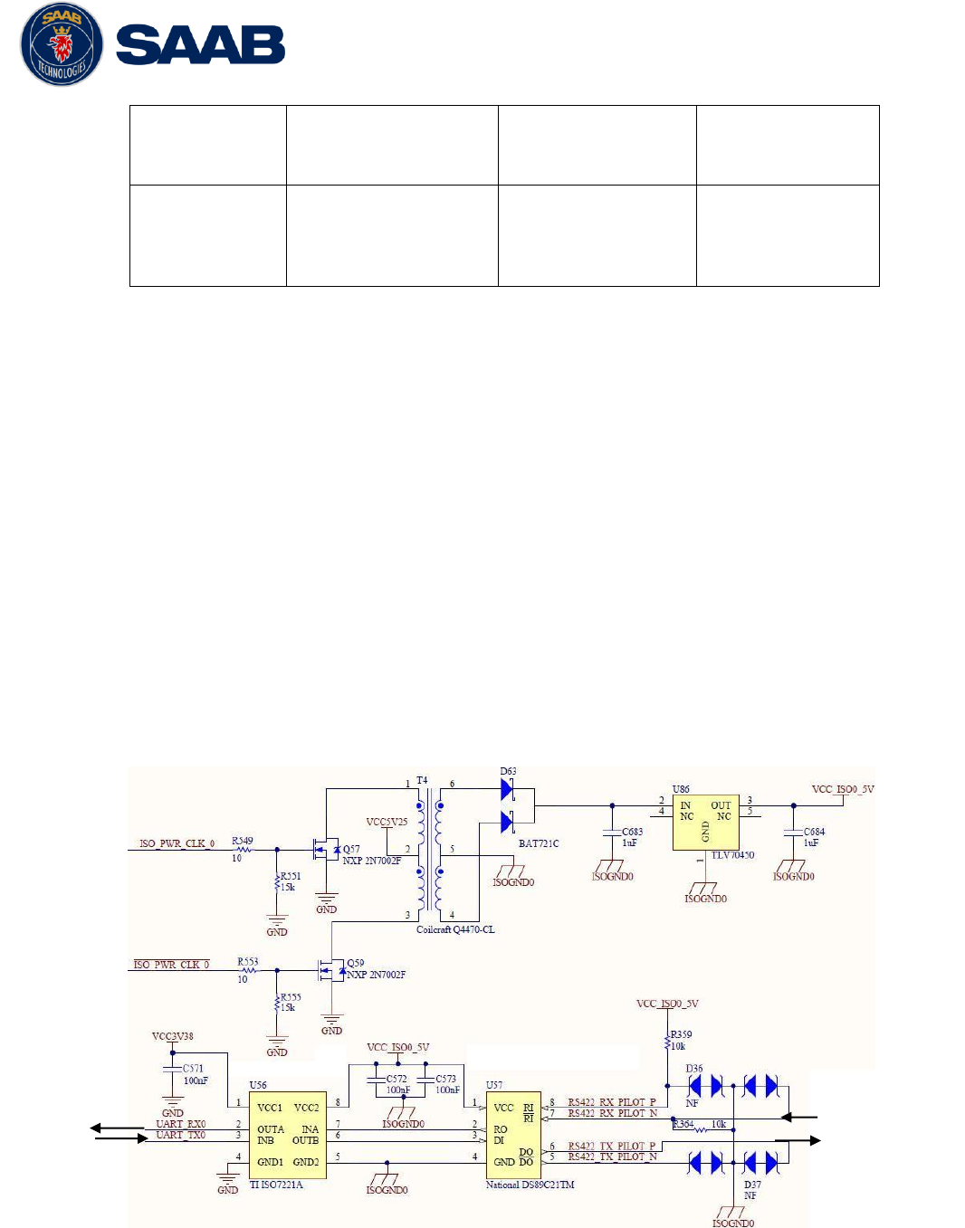
3.7.3 Schematics of an R5 SOLID serial transceiver
Each of the RS422 serial interfaces on the R5 SOLID fulfils the requirements of IEC
61162-2 and IEC 61993-2. A detailed schematic of one of the serial ports in the R5
SOLID is shown below.
Figure 9 – Serial Port Schematics
ISO Power
Internal
Signals to R5
Solid
To connected
equipment

R5 SOLID AIS System
INSTALLATION
7000 118-200, A4 Page 23
3.7.4 R5 Signal Cable, DSUB-Open, 7000 118-078, B
Pin
In/Out
Signal Name
Signal Type
Colour
1
Out
ECDIS - TxB (+)
RS422
White
2
Out
ECDIS - TxA (-)
RS422
Brown
3
In
Sensor1 - RxB (+)
RS422
Green
4
In
Sensor1 - RxA (-)
RS422
Yellow
5
In
Sensor2 - RxB (+)
RS422
Grey
6
In
Sensor2 - RxA (-)
RS422
Pink
7
In
Long Range - RxB (+)
RS422
Blue
8
In
Long Range - RxA (-)
RS422
Red
9
-
Long Range - GND
RS422
Black
10
-
ECDIS - GND
RS422
Violet
11
In
ECDIS – RxB (+)
RS422
Grey / Pink
12
In
ECDIS – RxA (-)
RS422
Red / Blue
13
-
Sensor1 – GND
RS422
White / Green
14
-
Sensor2 – GND
RS422
Brown / Green
15
In
Sensor3 – RxB (+)
RS422
White / Yellow
16
In
Sensor3 – RxA (-)
RS422
Yellow / Brown
17
Out
Long Range – TxB (+)
RS422
White / Grey
18
Out
Long Range – TxA (-)
RS422
Grey / Brown
19
-
Alarm Relay – GND
-
White / Pink
20
Out
Alarm Relay – Out
-
Pink / Brown
21
-
GND
-
White / Blue
22
In
Unlock Tx
Binary
Brown / Blue
23
-
Sensor3 – GND
RS422
White / Red
24
-
Alarm Relay - VCC
-
Brown / Red
25
In/Out
CAN (+)
Differential
CAN bus
N/A
26
In/Out
CAN (-)
Differential
CAN bus
N/A
Table 8 – 26-pin High Density D-sub
3.7.5 RS232 Signal Cable
Pin
Signal Name
1
Not Connected
2
Tx (Transponder side)
3
Rx (Transponder side)
4
Not Connected
5
GND
6
Not Connected
7
Not Connected
8
Not Connected
9
Not Connected
Table 9 – 9-pin female D-sub
R5 SOLID AIS System
INSTALLATION
7000 118-200, A4 Page 24
3.7.6 R5 Power Cable, 7000 118-077, A
Pin
Signal Name
Colour
1
24VDC positive
Red
2
GND
Black
3
External Switch (R)
Brown
4
External Switch (F)
Orange
Table 10 – 4-pin male circular ConXall
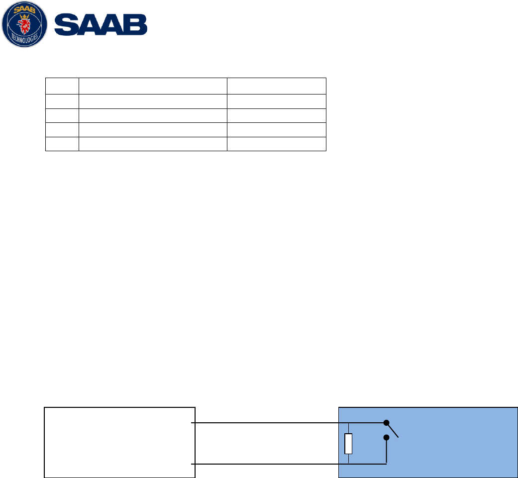
3.7.7 Blue Sign Connection
If the blue sign switch should be used, the parameter “External Switch” must be
configured to “Blue Sign” in Misc. Interface view accessed from Main Menu Config
Interfaces Miscellaneous.
The status of the blue sign can be controlled by input on the brown and orange wires of
the R5 Power Cable.
The status of the Blue Sign will be read by the R5 SOLID and output on the VHF data
link when operating in “Inland Mode” (see section 4.4.16 for more details). Connect the
blue sign switch to pin 3 (brown wire) and pin 4 (orange wire) of the R5 Power Cable
together with an external parallel resistor. When the switch is open, blue sign will be
off. When the switch is closed, blue sign will be on.
The external resistor value depends on the power supply voltage the R5 SOLID is
using:
24V: 10kΩ resistor, 10% tolerance
3.7.8 Silent Switch
It is possible to connect a silent switch to the R5 SOLID to quickly turn off
transmissions.
If a silent switch is to be used, the parameter “External Switch” must be configured to
“Silent Switch” in Misc. Interface view accessed from Main Menu Config
Interfaces Miscellaneous.
The silent switch should be connected in the same way as the blue sign switch.
However, the external resistor may be omitted for the silent switch.
When the circuit is closed (brown and orange wires connected with each other), the R5
SOLID will transmit as normal. When the circuit is open, the R5 SOLID will be
completely silent.
BLUE SIGN
SWITCH
R5 Power Cable Pin 3
R5 Power Cable Pin 4
External resistor
R5 SOLID AIS System
INSTALLATION
7000 118-200, A4 Page 25
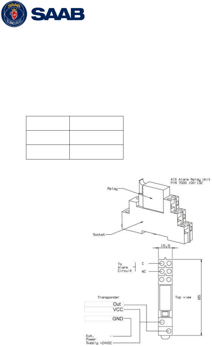
3.7.9 Alarm relay
It is required that the AIS alarm output (relay) is connected to an audible alarm device
or the ship‟s alarm system, if available.
Alternatively, the ship‟s BIIT alarm system may use the alarm messages output on the
AIS Presentation Interface (PI) provided the alarm system is AIS compatible. The AIS
Alarm Relay is either mounted on a DIN mounting rail or direct on the wall.
The alarm relay wires have the following colour codes in the 26-pole R5 SOLID signal
cable:
RELAY VCC
Brown/Red
RELAY GND
White / Pink
RELAY OUT
Pink / Brown
Table 11 – Alarm Relay wires
Figure 10 – Alarm Relay

R5 SOLID AIS System
INSTALLATION
7000 118-200, A4 Page 26
3.8 System Configuration
When the physical and electrical installation of the system is complete, the R5 SOLID
needs to be configured. The installer is required to set the parameters listed below. For
detailed information about the configuration parameters and how to set them, refer to
chapter 4.2.1 and 4.4.
MMSI number (Maritime Mobile Service Identity)
IMO vessel number (should be set to zero for Inland vessels)
Call Sign (Should be set to ship‟s ATIS code for Inland vessels)
Ship Name
Height Over Keel
Ship dimensions and antenna positions. Refer to chapter 4.4.4 Main Menu
Config Ship Dimensions for more information.
If the R5 SOLID is operating in Inland mode, the following parameters also need to be
configured:
Euro Number (ENI, unique European Identifier)
Euro Type (ERI code and standard AIS ship type will be set automatically by the
R5 SOLID when selecting a Euro Type from list in Ship Static view.
Quality setting for SOG, COG and HDG. Should be set to low if no type approved
sensor (e.g. a gyro or speed log) is connected to R5 SOLID.
When the R5 SOLID has been installed according to procedures described in previous
chapters, it is recommended to make a first functional check of the system. Check the
following things to ensure that the R5 SOLID is fully functional.
Check the Transmitted Own Ship Data view to make sure that the configured data
is sent by the R5 SOLID on the VHF link, refer to chapter 4.10 “View Transmitted
Own Ship Information” for more information.
Make sure that there are no unexpected active alarms in the alarm list, see
chapter 4.18 “Alarms”.
Perform a communication test to ensure that the R5 SOLID can send and receive
messages from another transponder. Refer to chapter 4.25 “Communication Test” for
information on how to perform a communication test.

R5 SOLID AIS System
OPERATION
7000 118-200, A4 Page 27
1
2
3
4
7
9
8
6
5
4 OPERATION
4.1 System Mode
The R5 SOLID can operate in two different system modes, Class A mode and Inland
mode. The Class A mode should be used for vessels falling under the carriage
requirements of Chapter V of the International Convention for the Safety of Life at Sea
(SOLAS).
The Inland mode should be used for vessels traveling on European inland waterways that
falls under the carriage requirements of European River Information Services (RIS). When
Inland mode is enabled, additional views for ETA/RTA messaging and convoy settings will
be enabled. The R5 SOLID will also output binary messages with Inland Static and
Voyage data.
As default, the R5 SOLID will operate in Class A mode. It is possible to switch system
mode in the System Settings view, see section 4.4.16 for more information.
4.2 LED’s and Controls
This section describes the controls and status LED‟s on the front panel of the R5 SOLID.
It is also possible to connect a USB keyboard via the USB Host interface that can be
found under the hatch of the front panel.
1 - STATUS LED (multi-colored)
This LED is constant green when the transponder is operating and no alarms are active.
The LED is constant red if there is an active alarm and it is flashing red if there is an
unacknowledged alarm.
2 - RX LED (yellow)
This LED is flashing yellow when the transponder is receiving a message on the VHF link.
3 - TX LED (red)
This LED is flashing red when the transponder is transmitting a message on the VHF link.
4 - LIGHT SENSOR

R5 SOLID AIS System
OPERATION
7000 118-200, A4 Page 28
The light sensor will automatically dim the backlight of the display depending on measured
input light to the sensor.
5 - ARROW KEYPAD and ENTER
The arrow keypad (< > and ∧ ∨ ) is used to navigate in menus, lists and edit fields. The
center button of the keypad is an ENTER button which is used to select the highlighted
choice in a menu, list or edit control.
6 - ESC
The ESC button is used to return to the previous screen or to cancel an edit change of a
data field.
7 - ALPHANUMERIC KEYS
These keys are used for entering text and numbers. To write a number in a numeric field,
press the key once. To write a character in a text field, press once for the character
associated with the key, twice for the second character and so on. When pressing twice
on key “1” when editing a text field, a popup view with special characters appears.
Choose the desired special character by using the ARROW KEYPAD and ENTER.
When a USB keyboard is used, the normal letters, numbers and special characters can be
used. Only American keyboard layout is supported.
8 - OPT
This button is an “Option key” which is only active in some of the dialogs. When pressed,
it gives the user a list of options that can be performed on the highlighted item. In e.g. the
Target List view the OPT button can be used to send an SRM to the highlighted target. In
the Main Menu view, the OPT button is used to quickly change navigational status. When
a USB keyboard is used, the ALT button of the keyboard corresponds to OPT button on
the R5 SOLID keypad.
If the OPT button is pressed for more than 5 seconds, the visual settings in the R5 SOLID
will be restored to default, i.e. LCD backlight, LED intensity and button backlight will all be
80% and day mode will be used.
9 - BACKSPACE
The BACKSPACE button is used to erase the character to the left of the marker in an edit
field.
4.2.1 Change Settings of a Parameter
Several of the views in the R5 SOLID contain parameters that can be edited. To edit a
parameter, select it by using the ARROW KEYPAD and press ENTER.
Then enter data in one of the following ways:
Numbers: Press the ALPHANUMERIC KEY that corresponds to each digit. To
delete a digit, press function key BACKSPACE. Some of the parameters are
decimal numbers. The OPT button can then be used to insert a decimal point.
Text: Press the ALPHANUMERIC KEY that corresponds to each character.
Press the key once for the first character, twice for the second character and so
on. Press the key “1” twice to, where allowed, bring up a menu for entering
special characters. To delete a character, press function key BACKSPACE.
When entering passwords both lower and upper case letters can be used. To
change between upper and lower case letters, press function key OPT and
choose “Caps Lock Off” or “Caps Lock On”.

R5 SOLID AIS System
OPERATION
7000 118-200, A4 Page 29
List of predefined values: Use the ∧ ∨ keys to select between the predefined
values.
List of predefined values and numeric input:
In some of the views like the AIS Message Send view where it is possible to
send an SRM to a target, it is possible to select an MMSI in a list of predefined
values. The predefined MMSI values are the MMSI numbers that have been
received by the transponder. It is also possible to enter a new MMSI number
that has not been received yet. To do this, simply input a numerical value with
the ALPHANUMERIC KEYS.
Press ENTER when done. If desired, use the ARROW KEYPAD keys to select a new
parameter to be edited, or navigate to the Save/Send button located above the list of
parameters and press ENTER to save the parameters / send the message.
Use the ESC key to undo changes and to return to the previous view.
NOTE: DO NOT TURN OFF TRANSPONDER WITHIN 2 SECONDS OF A
PARAMETER CHANGE!

R5 SOLID AIS System
OPERATION
7000 118-200, A4 Page 30
4.3 Main Menu – Tree View
Main Menu
Target List
Plot
Alarms
Messages
Voyage
Status
Maintenance
Long Range
AIS Messages
Persons On
Board
Inbox
Outbox
Send
ETA/RTA
Water Levels
Inbox
Outbox
Send
Only visible if System Mode is
set to ”Inland” and Ship Size
Mode is set to ”Simplified”
Ship Static
Status List
Non Func. Time
VHF Status
Comm.
Test
GPS Status
Update
Software
SW/HW Info
View Raw Data
Config
Ship
Dimensions
VHF Radio
Alarm
Password
Long Range
Display
Interfaces
Visual
Sound
Port Rate
Miscellaneous
Regional Areas
LR Broadcast
Settings
Time
System
Settings
Operational
Mode
Transmitted
Own Ship Data
Installation Test
AIS Voyage
Convoy
Settings
Language
Restore Config
R5 SOLID AIS System
OPERATION
7000 118-200, A4 Page 31
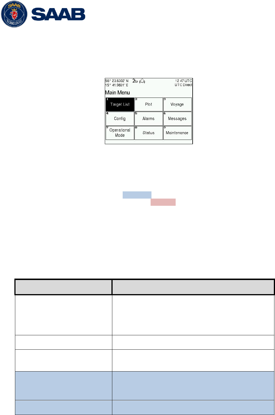
4.3.1 Navigating in Menus
Use the ARROW KEYPAD buttons < > and ∧ ∨ to navigate between the view buttons
in the different menus. Press the ENTER button to enter the currently selected view. It
is also possible to directly select a view by pressing the ALPHANUMERIC KEY that
corresponds to the number in the upper left corner of the view button.
Figure 11 – Main Menu
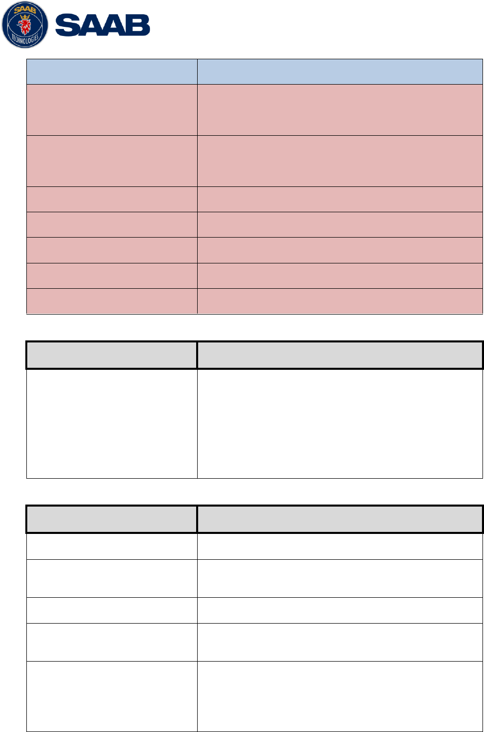
4.4 Configuration Parameters
This section describes the different configuration parameters that can be set in the R5
SOLID. Some of the parameters will only be available when operating in “Class A” mode,
these parameters are marked with blue color. Parameters that is only available when
operating in “Inland” mode will be marked with red color. Parameters that are common for
both system modes are white.
4.4.1 Main Menu Voyage AIS Voyage
The parameters in AIS Voyage view are used for input of voyage specific information
that is sent over the AIS link. These parameters should typically be configured before
each voyage.
When the R5 SOLID system mode is set to “Inland”, additional voyage parameters for
inland water way voyages are available. The system mode can be configured in the
System Settings view described in section 4.4.16.
Parameter Name
Description
Navigational Status
Changes the navigational status reported by own ship.
It is also possible to quickly change navigational status
by pressing the OPT button when standing in the Main
Menu.
Destination
The destination for the current voyage
Estimated Time of Arrival (ETA)
The estimated time of arrival to destination of current
voyage
Draught (Class A)
The vertical distance measured from the lowest point of
a ship‟s hull to the water surface, in meters (two
decimal precision)
Persons on Board
Total number of persons on board
R5 SOLID AIS System
OPERATION
7000 118-200, A4 Page 32
Hazardous Cargo (X,Y,Z,OS)
Classification of current cargo according to X,Y,Z,OS
Draught (Inland)
The vertical distance measured from the lowest point of
a ship‟s hull to the water surface, in meters (two
decimal precision)
Air Draught
The vertical distance measured from the ship‟s
waterline to the ship‟s highest point, in meters (two
decimal precision)
Hazardous Cargo (Blue Cones)
Blue cone classification of cargo
Loaded / Unloaded
Specifies if the ship cargo is loaded or unloaded
Crew Members
Number of crew members on board
Passengers
Number of passengers on board
Personnel
Number of shipboard personnel on board
4.4.2 Main Menu Operational Mode
Parameter Name
Description
Tx Mode
This parameter determines the transmission of the R5
SOLID. If set to “Silent”, the R5 SOLID will be
completely silent on the VHF radio and it will not
answer on interrogations.
If a silent switch is used, this parameter will be locked
and “Silent Switch Used” will be displayed as
parameter value.
4.4.3 Main Menu Config Ship Static
Parameter Name
Description
MMSI
Maritime Mobile Service Identity reported by own ship
IMO
International Maritime Organization number reported by
own ship
Ship Name
Ship name reported by own ship
Call Sign
Call sign reported by own ship. Shall be set to ATIS
code for Inland vessel installations.
Height over Keel
Height over keel in meters (one decimal precision).
Height over Keel information is sent as a response to
an “Extended Ship Static and Voyage Related Data”
request message.
R5 SOLID AIS System
OPERATION
7000 118-200, A4 Page 33
Ship Type (IMO)
Type of Ship according to ITU 1371-3. Both numerical
input and selection in drop list is possible.
Euro Number
Unique European Vessel Identification Number
reported by own ship
Euro Type
Ship or combination type according to numeric ERI
classification
Quality Speed
Shall be set to low if no type approved speed sensor is
connected to transponder
Quality Course
Shall be set to low if no type approved course sensor is
connected to transponder
Quality HDG
Shall be set to low if no type approved heading sensor
is connected to transponder
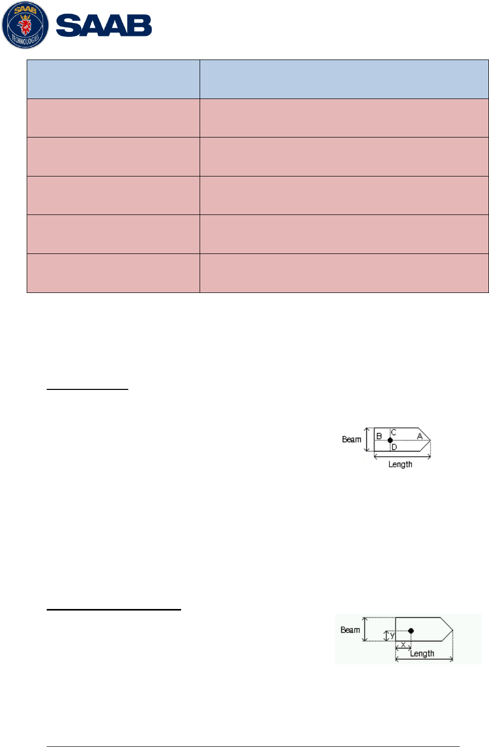
4.4.4 Main Menu Config Ship Dimensions
The parameters in the Ship Dimensions view depends on the configuration parameter
“Ship Size Mode” in the Misc Interfaces view. The Ship Size Mode parameter can be
set to either Standard or Simplified (default). The Ship Size Mode affects how the user
should input ship size and antenna position information and how it is interpreted.
Standard Mode
In this mode the user must input:
Convoy/ship length [m] (one decimal precision)
Convoy/ship beam [m] (one decimal precision)
A, B, C, D for internal antenna [m]
A, B, C, D for external antenna [m]
It is the users responsibility to input correctly rounded data (A+B = Convoy/ship length
rounded up, C+D = Convoy/ship beam rounded up).
If the user inputs data which is not correctly rounded the “Ship size mismatch” alarm
will be activated.
The output on the AIS data link will be exactly the values input by the user.
Simplified Mode (default)
In this mode the user inputs:
Ship length [m] (one decimal precision)
Ship beam [m] (one decimal precision)
X, Y for internal antenna relative to ship [m] (one decimal precision)
X, Y for external antenna relative to ship [m] (one decimal precision)
When operating in Inland Mode, extra convoy size can be added to ship dimension
R5 SOLID AIS System
OPERATION
7000 118-200, A4 Page 34
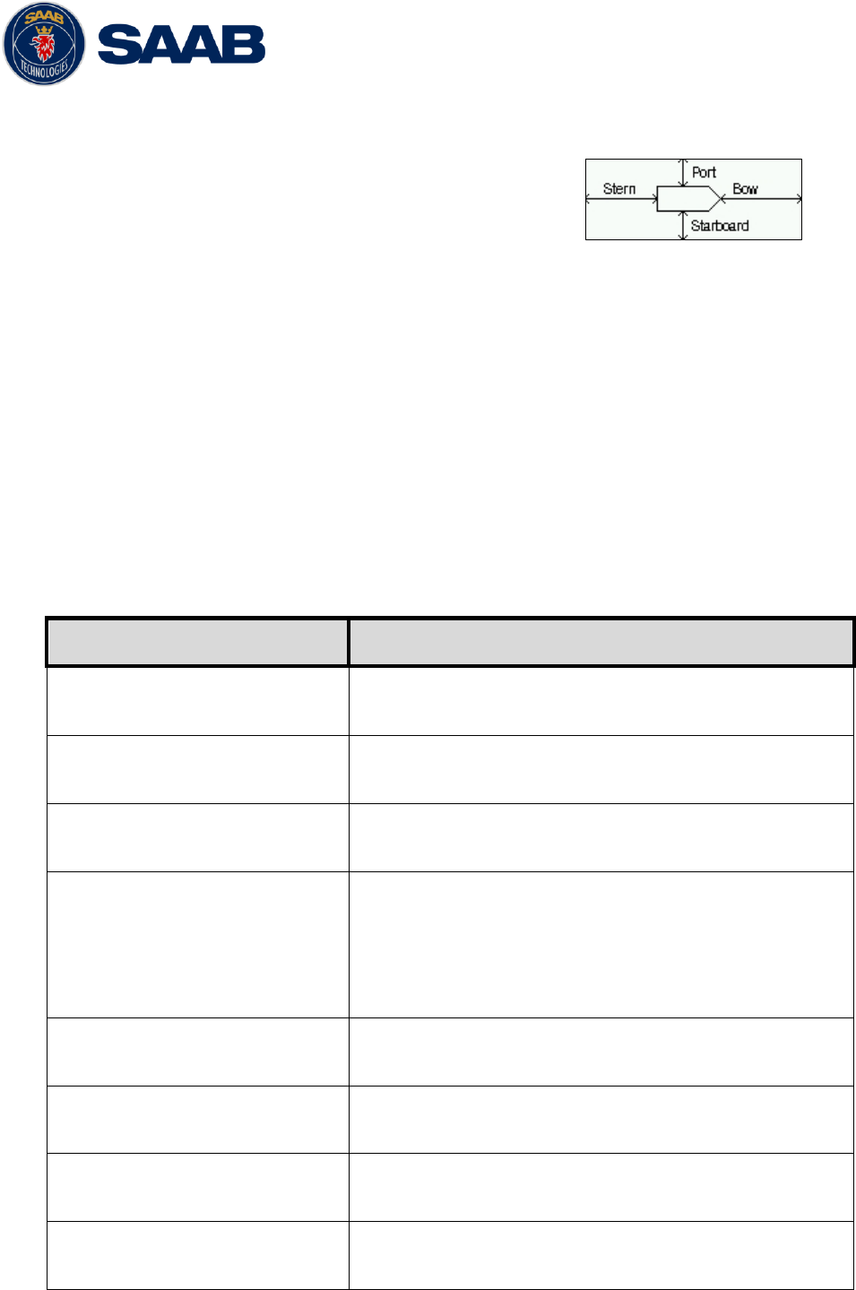
Extra convoy size on each side (value = 0 if convoy not used):
Bow [m] (one decimal precision)
Stern [m] (one decimal precision)
Port side [m] (one decimal precision)
Starboard [m] (one decimal precision)
The extra convoy parameters can be configured from Main MenuVoyageConvoy
Settings when the Ship Size Mode is set to “Simplified”.
In this mode there is no way for the user to input mismatching data, all parameters
uses the same precision and each measurement is entered only once (in standard
mode it is for example possible to enter three different lengths of ship: Convoy/ship
length, internal A+B and external A+B). In simplified mode the transponder will
automatically calculate and correctly round the A, B, C and D values reported on the
VHF link.
4.4.5 Main Menu Config VHF Radio Regional Areas
This view shows the regional areas set in the transponder. To make a new regional
area or to edit or delete an existing regional area, press the OPT button and choose
the desired action. The following parameters can be edited when “New Area” or “Edit
Area” is chosen:
Parameter Name
Description
Channel A
The channel number for AIS channel A (2087 = default)
that should be used in the regional area.
Channel B
The channel number for AIS channel B (2088 = default)
that should be used in the regional area.
Zone Size
The transitional zone size of the regional area in
nautical miles (NM).
Tx Mode
Decides which channels the transponder will use when
transmitting in the regional area.
When set to “None”, the transponder will stop
automatic transmissions on AIS channels A and B but it
will still answer when interrogated on the DSC channel.
Power
Transmission effect for the transponder in the regional
area. High = 12,5 W, Low = 1 W.
LAT NE
The latitude coordinate for the North East corner of the
regional area
LON NE
The longitude coordinate for the North East corner of
the regional area
LAT SW
The latitude coordinate for the South West corner of the
regional area
R5 SOLID AIS System
OPERATION
7000 118-200, A4 Page 35
LON SW
The longitude coordinate for the South West corner of
the regional area
4.4.6 Main Menu Config VHF Radio LR Broadcast Settings
Parameter Name
Description
LR Broadcast Ch. 1
The channel A number for broadcasting long range
message 27. The message is sent every 6 minute on
each channel so if both channel A and B are configured
a message 27 will be broadcasted every 3 minute. If
this parameter is set to zero no long range broadcast
transmissions will be sent on this channel.
LR Broadcast Ch. 2
The channel B number for broadcasting long range
message 27. The message is sent every 6 minute on
each channel so if both channel A and B are configured
a message 27 will be broadcasted every 3 minute. If
this parameter is set to zero no long range broadcast
transmissions will be sent on this channel.
4.4.7 Main Menu Config Alarm
In this view all alarms can be configured to either “Enabled” or “Disabled”. When the
alarm is enabled, an active alarm will affect the external alarm relay, the buzzer in the
R5 SOLID and show a popup dialog in the display. When the alarm is set to disabled it
will not affect anything when the alarm becomes active. For more information about the
alarm view, refer to chapter 4.18 “Alarms”. For a list of all the alarms that can occur,
refer to chapter 7.3 “Troubleshooting with alarm messages.”
4.4.8 Main Menu Config Password
Parameter Name
Description
New User Password
Changes the user level password for the R5 SOLID.
The default user level password is “user”
New Admin Password
Changes the admin level password for the R5 SOLID.
The default admin level password is “admin”
Restore Code
It is possible to restore both user password and admin
password to the default values above with a secret
restore code.
To obtain the restore code, contact Saab
TransponderTech Support and be prepared to provide
the serial number of the transponder unit.
4.4.9 Main Menu Config Long Range
Parameter Name
Description

R5 SOLID AIS System
OPERATION
7000 118-200, A4 Page 36
Reply Mode
When set to “Auto” the R5 SOLID will automatically
respond to any Long Range interrogation messages.
When set to “Manual” the operator should send a
respond or refusal to any Long Range interrogation
message. This can be done from the Long Range view
that is accessed from Main Menu
Messages
Long
Range. For more information see section 4.14 Long
Range Interrogations.
The information that is sent in a response is
automatically filled in by the R5 SOLID depending on
the Long Range filter settings (the parameters below).
Ship ID (A)
Filter setting that defines if a Long Range response
message should include ship name, call sign and IMO
number.
Message Date/Time (B)
Filter setting that defines if a Long Range response
message should include information about date and
time of message composition.
Latitude / Longitude (C)
Filter setting that defines if a Long Range response
message should include position.
Course Over Ground (E)
Filter setting that defines if a Long Range response
message should include COG.
Speed Over Ground (F)
Filter setting that defines if a Long Range response
message should include SOG.
Destination And ETA (I)
Filter setting that defines if a Long Range response
message should include destination and ETA.
Draught (O)
Filter setting that defines if a Long Range response
message should include draught.
Ship Type And Cargo (P)
Filter setting that defines if a Long Range response
message should include ship type and cargo
information.
Ship Size And Type (U)
Filter setting that defines if a Long Range response
message should include ship‟s length, beam and type.
Persons On Board (W)
Filter setting that defines if a Long Range response
message should include number of persons on board.
4.4.10 Main Menu Config Display Visual
It is possible to completely turn off the backlight on LCD, buttons and LED‟s. It may
then be difficult to read the R5 SOLID display and find the way to the correct
configuration parameter in order to increase the backlight again. If this should happen,
it is possible to hold down the OPT button for 5 seconds to restore the backlight to
80%.
R5 SOLID AIS System
OPERATION
7000 118-200, A4 Page 37
Parameter Name
Description
Dimming Mode
If set to “Manual”, the LCD backlight, button backlight
and LED brightness are controlled by the user with the
parameters described below.
If set to “Automatic”, the LCD backlight, button
backlight and LED brightness will automatically be
controlled with the light sensor on the front of the R5
SOLID. The less ambient light registered by the light
sensor, the lower percentage of backlight and
brightness will be used.
Toggle Day/Night
Toggle between day or night mode. In Day mode the
display background is white and in night mode the
background is black. There are also separate settings
for the LCD backlight, LED intensity and button
backlight in the different day/night modes.
Backlight
Changes the LCD backlight where 0% is completely
turned off and 100 % is maximum brightness.
LED Light Intensity
Changes the light intensity of the three LED‟s on the
front of the R5 SOLID.
It is possible to turn off the LED‟s completely by setting
a 0% light intensity. However, if there is an active,
unacknowledged alarm in the R5 SOLID, the light
intensity of LED‟s will temporarily be set to 10% until
the alarm is acknowledged.
Button Illumination
Changes the brightness of the button backlight on the
R5 SOLID.
4.4.11 Main Menu Config Display Sound
Parameter Name
Description
Alarm Waiting For ACK
Determines how the R5 SOLID sound buzzer should
behave when an alarm is active and waiting for
acknowledgement. This setting does NOT affect the
behavior of the alarm relay or any external alarm
system.
Long Range Message
Controls the behavior of the R5 SOLID sound buzzer
when an LR interrogation message is received.
AIS Message
Controls the behavior of the R5 SOLID sound buzzer
when a SRM or binary text message is received.
Inland RTA
Controls the behavior of the R5 SOLID sound buzzer
when an Inland RTA (Recommended Time of Arrival)
R5 SOLID AIS System
OPERATION
7000 118-200, A4 Page 38
message is received.
4.4.12 Main Menu Config Display Time
Parameter Name
Description
Time Zone
This parameter defines if the times that are displayed in
the R5 SOLID should be in UTC or LOC (local) time. If
local time is chosen, the offset from UTC must be
specified with the three parameters listed below.
Offset sign
The sign of the local time offset from UTC.
Hours
The local time hour offset from UTC.
Minutes
The local time minute offset from UTC.
4.4.13 Main Menu Config Interface Language
Parameter Name
Description
Language
Changes the language in all the menus and views of
the R5 SOLID. The changes will take effect
immediately when pressing “Save”.
4.4.14 Main Menu Config Interface Port Rate
Parameter Name
Description
Baud Rate
Changes the baud rate (bits per second) for the
corresponding serial port.
Checksum
When set to “Required”, all messages that are input on
the corresponding serial port to the R5 SOLID must
have a valid checksum.
When set to “Disabled”, messages both with and
without checksum are accepted on the corresponding
serial port.
4.4.15 Main Menu Config Interface Miscellaneous
Parameter Name
Description
SSD Password
Changes the value of the SSD password level. When
set to “None”, no password is required when
configuring the transponder with an SSD sentence from
e.g. an ECDIS via the serial port interface.
When set to “User”, an SPW sentence with the correct
user level password must be sent before the SSD on
R5 SOLID AIS System
OPERATION
7000 118-200, A4 Page 39
the serial port interface.
Ship Size Mode
This affects how the user should input the ship size,
convoy size and antenna positions. See section 4.4.4
for more details.
AIS GPS Output Port
Defines on which serial port the R5 SOLID should
output data from the internal GPS. When set to “None”
no internal GPS data will be output.
External Switch
This parameter specifies if there is a blue sign switch or
silent switch connected to the orange and brown wires
of the R5 SOLID Power Cable.
If no switch is used, set the parameter to “No Function”.
See sections 3.7.7 and 3.7.8 for more information
about the blue sign switch and silent switch.
Require Text Msg ACK
This parameter determines if an ACK msg is required
as a response when sending addressed binary text
messages to another target.
4.4.16 Main Menu Config System Settings
Parameter Name
Description
System Mode
Determines if the R5 SOLID should operate as a Class
A transponder or as an Inland transponder. This
parameter affects which config parameters and menus
that are visible in the system.
Range Unit
This parameter determines the unit for the range value
of targets in the Target List, Extended Info view and
Plot view. The range value can be calculated in nautical
mile (NM), kilometer (km) or statute mile (Sm).
Speed Unit
This parameter determines the unit for the SOG value
of targets in Extended Info view and Plot view. The
SOG value can be calculated in knots (kn), kilometer
per hour (km/h) or miles per hour (mph).
Plot Compass
This parameter determines how the plot of AIS targets
should be oriented.
If set to “North Always Up”, the plot will always have
north up and own ship will rotate according to heading
input.
If set to “Own Ship Bow Always Up”, the plot will always
have own ship pointing up and rotate the rest of the plot
according to heading input.
R5 SOLID AIS System
OPERATION
7000 118-200, A4 Page 40
4.4.1 Main Menu Maintenance Installation Test
Parameter Name
Description
Position Source
This parameter specifies which port the R5 SOLID
should use as its external position source. The default
value of this parameter is “Automatic” which means that
the R5 SOLID will accept position information on any
port and use the information on the port with highest
priority.
If Position Source is set to anything else than
“Automatic”, the R5 SOLID will only accept position
information if it comes from the port specified by this
parameter.
SART Test Mode
This parameter determines if SART Test targets should
be displayed in target list and Plot of the R5 SOLID.
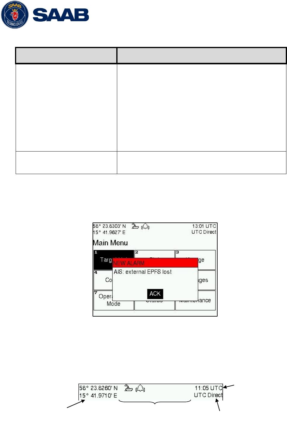
4.5 Alarm and Alert Pop-ups
The R5 SOLID features alarm and alert pop-ups that can appear any time during
operation. To acknowledge an alarm or alert message, press ENTER. An example of an
alarm message is shown below.
Figure 12 – Main Menu
4.6 Status Bar
The top of the screen of the R5 SOLID always displays a summary of the system‟s status.
See illustration below.
Current position
Status icons
Current time
synchronization state
Current time

R5 SOLID AIS System
OPERATION
7000 118-200, A4 Page 41
If a valid navigation position is available, it is displayed to the left. The status icons are
displayed in the middle and the current time is shown to the right. Time is either UTC or
local (LOC). Beneath the current time there is also information about the transponders
synchronization state. The R5 SOLID features a graceful degradation of the
synchronization state, which can be one of the following:
UTC Direct – This is the normal state where the R5 SOLID gets the UTC time
from its own internal GPS receiver.
UTC Indirect – The R5 SOLID is synchronizing based on receipt of data from
another transmitter that is working in UTC Direct.
NOTE: It is possible to be in UTC Indirect but still have a valid position in the upper
left corner of the status bar. In a Class A installation the position information from
an external GPS sensor has higher priority, but the UTC time is always taken from
the internal GPS receiver.
Base Station – This state is used when neither direct nor indirect UTC
synchronization can be obtained. The R5 SOLID will then synchronize to the
nearest base station, if any.
Semaphore – This is the last fallback state. The R5 SOLID will then synchronize
to the transmitter that is indicating the largest number of other received
transmitters. This station then becomes a „semaphore‟ for the AIS data link.
4.7 Status Icons
The status icons that can be displayed are:
Unread message (safety related message, text message or RTA)
Unread Long Range message (auto reply)
Unread Long Range message (manual reply)
Active alarms
1W mode (Indicates 1 Watt TX mode for Tankers is enabled.) See NOTE below
for details.
Blue Sign On (Only available when Inland Mode is active)
Blue Sign Off (Only available when Inland Mode is active)
Silent Mode activated, either with Tx Mode parameter or silent switch.
Navigational status, being one of:
Navigational status is undefined
At anchor or moored
Under way using engine
Navigational status is one of: Not under command, Restricted manoeuvrability,
Constrained by her draught, Aground, Engaged in fishing, Under way sailing, Reserved
for future use.
NOTE: The transponder will automatically engage 1W mode when the following
conditions are met: Ship type = Tanker, Nav Status = Moored and SOG <= 3
knots, otherwise 1W mode will be automatically disengaged. The Tanker 1W
mode is fully automatic cannot be disengaged by other external control.
R5 SOLID AIS System
OPERATION
7000 118-200, A4 Page 42
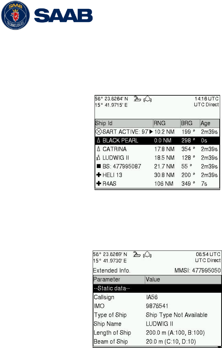
4.8 View Remote Ship Information
The R5 SOLID will power up in Target List view. This view, also referred to as the minimal
display, is accessed from the Main Menu view. The Main Menu view can be reached by
pressing ESC repeatedly from any other view. The Target List view displays a list of all
targets sorted by range from own ship (closest first). The list includes MMSI, ship‟s name,
range (RNG) and bearing (BRG).
Figure 13 – Target List
For extended information about a target in the list, select the ship with the ∧ ∨ key and
press ENTER.
The Extended Information view includes static, dynamic and voyage related data for the
selected target.
Figure 14 – Extended Info
Press ESC to return to Target List view.
The OPT button can be used in the Target List view to send a safety related message
(SRM) to the selected target. For more information about AIS messages, refer to section
4.12.
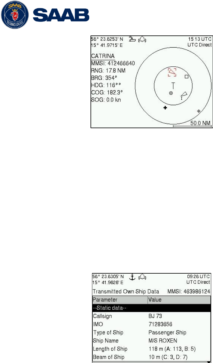
4.9 View Plot of Targets
The location of targets relative to your own ship is visualized in the Plot view. The view is
accessed from the Main Menu view. Use the ARROW KEYPAD < > to select any of the
targets on the display or ∧ ∨ to Zoom In and Zoom Out.
R5 SOLID AIS System
OPERATION
7000 118-200, A4 Page 43
Figure 15 – Target Plot
For extended information about a target select it using the < > key and press ENTER.
The own ship target is displayed as a „T‟ shaped symbol. Class B targets are indicated by
a „B‟ appended to the target icon and Inland targets are indicated by either an „I‟ or by a
blue sign symbol appended to the target (not shown in the figure above).
The OPT button can be used in the Plot view to send a safety related message (SRM) to
the selected target. For more information about AIS messages, refer to section 4.12.
4.10 View Transmitted Own Ship Information
The information transmitted by the R5 SOLID on the VHF link is viewed in the Transmitted
Own Ship Data view. This view is accessed from Main Menu
Status view and includes
the static, dynamic and voyage related data actually sent by the R5 SOLID. The view
reflects the contents of the last transmitted AIS message, thus there may be some delay
from the time the parameters are entered until they are displayed in the Transmitted Own
Ship Data view.
Figure 16 – Transmitted Own Ship Data
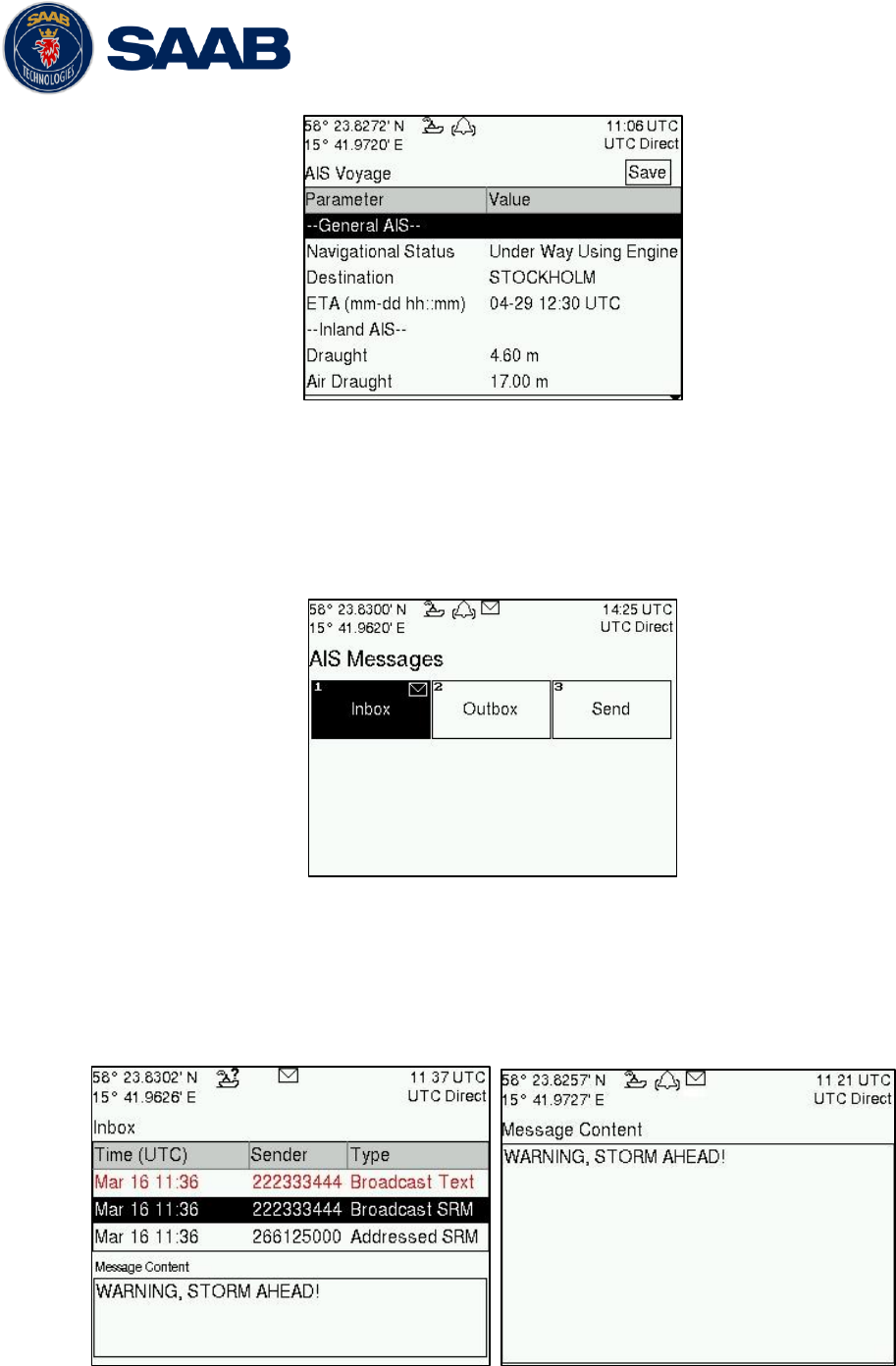
4.11 Enter and Read Voyage Related Information
Voyage related information (for transmit via AIS) is displayed in the AIS Voyage view. The
view is accessed from Main Menu
Voyage
AIS Voyage. Voyage related data includes
destination, estimated time of arrival (ETA) and number of people aboard.
R5 SOLID AIS System
OPERATION
7000 118-200, A4 Page 44
Figure 17 – AIS Voyage
4.12 Handling Safety Related Messages (SRM) and Text Messages
Safety related messages (SRMs) and text messages can be sent to specific targets
(addressed messages) or broadcast to all targets. Inbox, Outbox and Send view for SRMs
and text messages can be accessed from Main Menu
Messages
AIS Messages.
Figure 18 - AIS Messages
4.12.1 Read Received Messages
Received messages can be accessed in the Inbox view. Unread SRMs and text
messages are indicated with a letter icon in the status bar and are marked with red
color in the inbox.
Figure 19 – AIS Message Inbox
R5 SOLID AIS System
OPERATION
7000 118-200, A4 Page 45
Select a message with ARROW KEYPAD buttons ∧ ∨. A preview of the selected
message is shown at the bottom of the screen. To read the entire message and mark it
as being read, press ENTER. When the message is read, navigate back to the inbox
by pressing ESC.
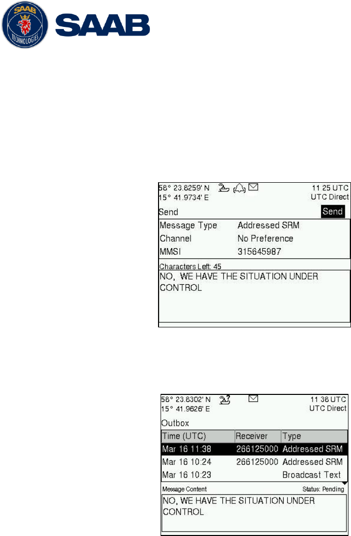
4.12.2 Send SRMs and Text Messages
SRMs are composed and sent in the Send view accessed from Main
MenuMessagesAIS MessagesSend. Use the ARROW KEYPAD buttons ∧ ∨ to
navigate between the text input field, list of parameters and “Send” button.
Figure 20 – AIS Message Send view
Sent messages can be viewed in the Outbox view accessed from Main
Menu
Messages
AIS Messages
Outbox.
Figure 21 – AIS Message Outbox
4.13 Send Persons On Board
In the Send Persons On Board view it is possible to send information about number of
persons on board (PoB) to another vessel. The PoB message can be sent as either
addressed or broadcast. The PoB message can also be sent in two different versions:
The IMO version sends the total number of persons on board as a binary message
with international FI branch 16.
The Inland (IWW) version sends a message with number of crew, personnel and
passengers as a binary message with inland branch FI55. The information sent in
the messages is automatically filled in by the R5 SOLID depending on the voyage
configuration made in Main Menu
Voyage
AIS Voyage.
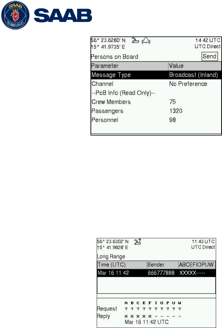
R5 SOLID AIS System
OPERATION
7000 118-200, A4 Page 46
Figure 22 – Persons On Board
4.14 Long Range Interrogations
AIS base stations can send long range interrogation messages to poll for certain
information from the R5 SOLID. A received interrogation message is indicated by a LR
icon in the status bar. If the “Long Range Reply Mode” parameter has been configured to
“Auto”, the R5 SOLID will automatically send a response to the interrogating base station.
If the “Long Range Reply Mode” parameter is set to “Manual”, the operator must send a
response or refusal from the Long Range Message view accessed from Main Menu
Messages
Long Range. For more information about the “Reply Mode” parameter and
Long Range filter settings, see section 4.4.9.
Figure 23 – Long Range
To send a reply or refusal to the interrogation or to delete an interrogation from the
message list, use the ARROW KEYPAD buttons ∧ ∨ to mark the desired interrogation and
then press the OPT button and choose the desired option.
The Long Range view uses the following symbols to indicate the status of a request or
reply message:
? – The information is requested by the sender
X – The information is available and provided
! – The information request is refused.
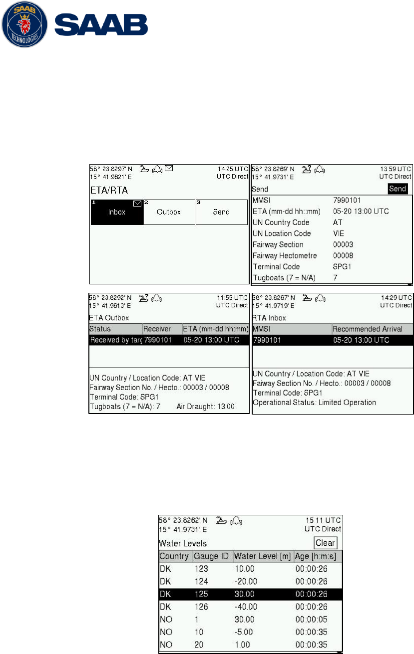
R5 SOLID AIS System
OPERATION
7000 118-200, A4 Page 47
4.15 Inland ETA and RTA
The R5 SOLID has capability to send Inland ETA (Estimated Time of Arrival) messages
and receive Inland RTA (Recommended Time of Arrival) messages which are used when
communicating with ports, locks and bridges on the inland water ways. This is done from
the ETA/RTA view that can be accessed from Main Menu
Messages
ETA/RTA. Sent
ETA messages can be viewed in the outbox, received RTA messages can be viewed in
the inbox and new ETA messages can be composed in the Send view.
Figure 24 – ETA/RTA
4.16 Inland Water Levels
The R5 SOLID can receive and display Inland branch FI 24 water levels messages. All
received water levels messages can be viewed in the Water Levels view that can be
accessed from Main Menu
Messages
Water Levels.
Figure - Inland Water Levels
4.17 Regional Areas
All regional areas that are set in the R5 SOLID can be viewed in the Regional Areas view
which is accessed from Main Menu
Config
VHF Radio
Regional Areas. The list
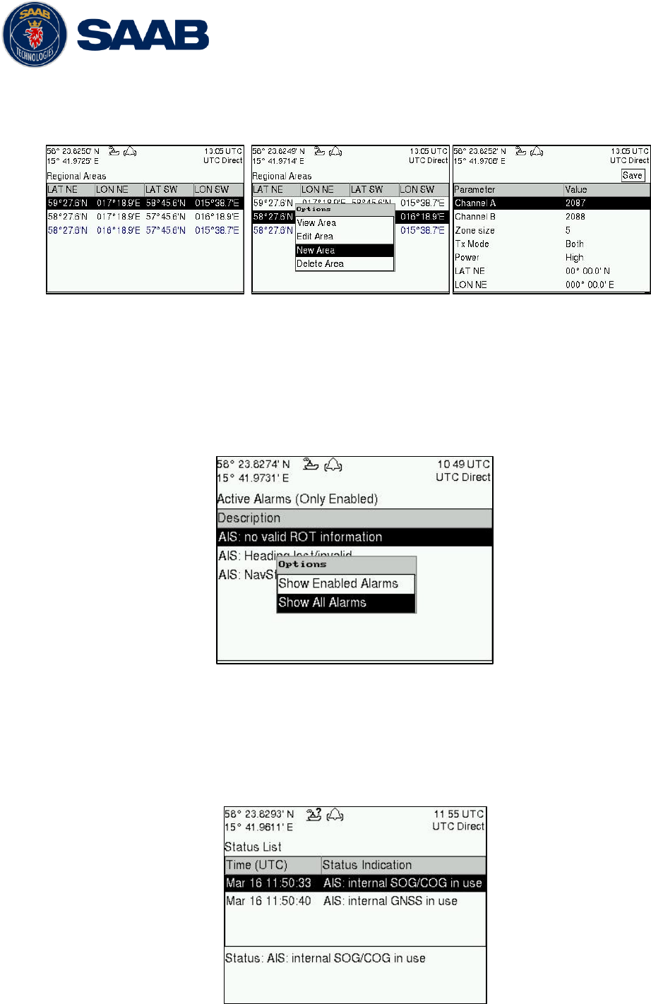
R5 SOLID AIS System
OPERATION
7000 118-200, A4 Page 48
shows the north east and south west corners of the area. The area is marked with blue
color if the area is in use by the R5 SOLID. To view more information about the area, edit
the area or create a new area, press the OPT button and choose the desired option.
Figure 25 – Regional Areas
4.18 Alarms
All currently active and enabled alarms are shown in the Alarm view that can be accessed
from Main Menu
Alarms. As default, only alarms that are configured as “Enabled” will be
shown in the list. It is possible to also show disabled active alarms by pressing OPT
button and choose “Show All Alarms”. For a list of all alarms, see chapter 7.3.
Figure 26 - Alarms
4.19 Status List
Current statuses of indications are listed in the Status List view that can be accessed from
Main Menu
Status
Status List. The different status indications that can occur are
listed in chapter 7.8.
Figure 27 - Status List
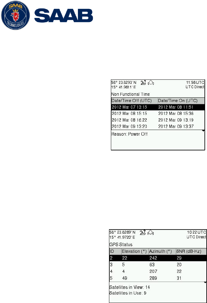
R5 SOLID AIS System
OPERATION
7000 118-200, A4 Page 49
4.20 Non Functional Time
This view displays information about times when the R5 SOLID has been turned off or not
been transmitting for some other reason for more than 15 minutes. The view is accessed
from Main Menu
Status
Non Func. Time.
Figure 28 - Non Functional Time
4.21 GPS Status
This view displays the satellites received by the R5 SOLID internal GPS receiver. The list
is sorted by the satellites ID (PRN number) and show elevation, azimuth and signal to
noise ratio (SNR) for each satellite. The view also displays the total number of satellites in
view and the total number of satellites used in the position calculation reported by GGA
sentence.
Figure 29 – GPS Status
4.22 View Raw Data
This view displays the incoming data to the R5 SOLID on the selected port. It is also
possible to pause the data on the screen by pressing the Freeze button. Use the ARROW
KEYPAD buttons ∧ ∨ to navigate to the Freeze button and press ENTER. The View Raw
Data view can be a helpful tool when trouble shooting the system to see what sensor input
the R5 SOLID is actually receiving on each port. The view can be accessed from Main
Menu Status View Raw Data.
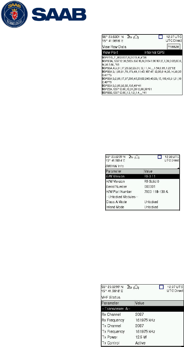
R5 SOLID AIS System
OPERATION
7000 118-200, A4 Page 50
Figure 30 - View Raw Data
4.23 SW/HW Info
This view displays the software and hardware revisions for the R5 SOLID and is accessed
from Main Menu
Status
SW/HW Info. NOTE: This information should always be
provided when in contact with Saab TransponderTech support.
Figure 31 - SW/HW Info
4.24 VHF Status
The VHF Status view shows the currently used settings for the VHF radio. Channel
number, frequency, power and operation mode are displayed for each VHF transceiver in
the R5 SOLID. This information is useful when troubleshooting to make sure that the R5
SOLID transponder uses the expected VHF radio settings. If e.g. a regional area is set
and in use, this will affect the parameters in the VHF Status view.
Figure 32 - VHF Status
4.25 Communication Test
When installing the R5 SOLID, or when performing annual testing, a communication test
shall be done to ensure that other transponder system can receive the R5 SOLID
transmissions. This can be done from the Communication Test view accessed from Main
Menu
Maintenance
Comm. Test.
When entering the Communication Test view a suggested target with a suitable range
(between 15 NM and 25 NM) will be selected in the MMSI parameter field if such a target
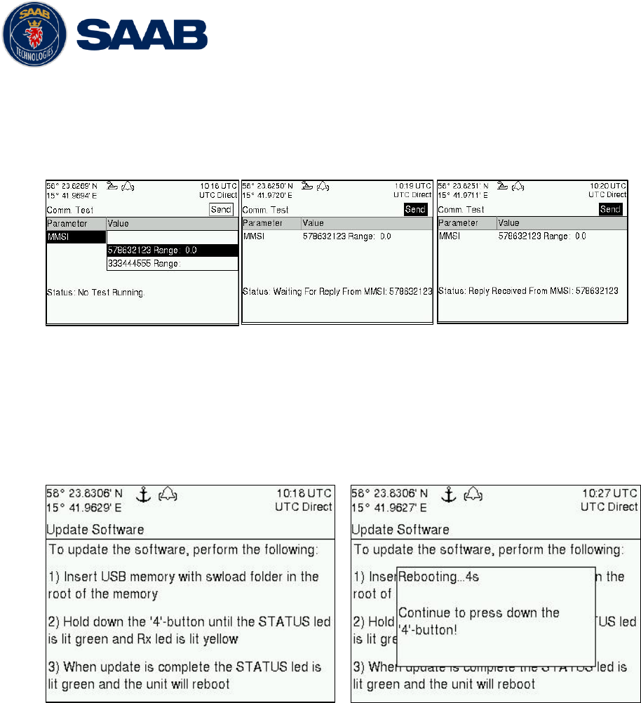
R5 SOLID AIS System
OPERATION
7000 118-200, A4 Page 51
has been received by the R5 SOLID. It is however possible to select a different target for
the communication test. To start the test, use the ARROW KEYPAD button ∧ to select the
“Send” button and press ENTER. The status of the test will be shown beneath the
parameter list. If no response is received within 15 sec from the selected target a fail
message will be shown.
Figure 33 - Communication Test
4.26 Update Software
The software in the R5 SOLID is easy upgradable via the USB Host interface located
behind the front hatch. To perform a software update, follow the instructions in the Update
Software view which can be accessed from Main Menu
Maintenance
Update Software.
For more information about the upgrade procedure, refer to chapter 5 Software Upgrade.
Figure 34 - Update Software
4.1 Restore Config
All config parameters described in section 4.4 “Configuration Parameters” can be set to
default values from the Restore Config view which can be accessed from Main Menu
Maintenance
Restore Config.
NOTE: The MMSI parameter will also be reset to zero and therefore the transponder
will stop transmitting and the alarm “Tx Malfunction” becomes active.
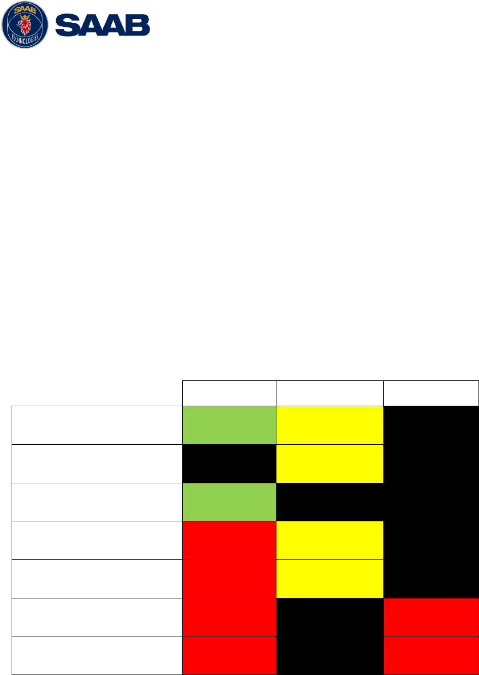
R5 SOLID AIS System
SOFTWARE UPGRADE
7000 118-200, A4 Page 52
5 SOFTWARE UPGRADE
Note: After updating the software add a sticker stating the new software version close
to the product label.
The R5 SOLID is easy upgradable through the USB host interface located behind the front
hatch. To upgrade the software in the R5 SOLID, perform the following steps:
Unzip the R5 SOLID upgrade package in the root folder of an USB memory stick.
There should now be a folder called swload in the USB root folder.
Insert the USB memory stick in the USB host interface located behind the front hatch.
Hold down the „4‟-button on the front of the R5 SOLID and reboot the system. The „4‟-
button must be held down until the STATUS LED is lit green and Rx LED is lit yellow.
The software upgrade is complete when the STATUS LED is lit green. The R5 SOLID will
automatically reboot after 3 seconds. Check that correct SW has been loaded in the SW/HW
Info view which can be accessed through Main Menu
Status
SW/HW Info.
If the upgrade process fails, The STATUS LED will be lit red and one of the Rx LED or Tx
LED starts blinking. Should this happen, hold down the „4‟-button and reboot the R5 SOLID
to try again.
The software upgrade can also be initiated from the Update Software view in the R5 SOLID.
Refer to chapter 4.26 Update Software for more information.
STATUS
Rx
Tx
Upgrade mode started
GREEN
YELLOW
Upgrade in progress
Blinking YELLOW
Upgrade complete (automatic
reboot after 3 sec)
GREEN
Error: USB Not Found
RED
Blinking YELLOW
0.5Hz
Error: No SW found on USB
RED
Blinking YELLOW
4Hz
Error: Flash erase failed
RED
Blinking RED
0.5 Hz
Error: Flash write failed
RED
Blinking RED
4 Hz
Table 12 – LED Indicators during Software Upgrade

R5 SOLID AIS System
TECHNINCAL SPECIFICATIONS
7000 118-200, A4 Page 53
6 TECHNINCAL SPECIFICATIONS
6.1 Physical
Dimensions:
Height: 87 mm
Width: 238 mm
Depth: 173 mm
Weight:
1.8 kg
6.2 Electrical
Input Voltage:
24 VDC
Power Consumption:
17 W (0.7 A @ 24 VDC input voltage)
6.3 Environmental
Temperature:
-15˚C to +55˚C (Operational)
-30˚C to +80˚C (Storage)
Vibrations:
IEC 60945 ed. 4
EMC:
IEC 60945 ed. 4
Radio Type Approval:
IEC 61993-2 ed. 2
Compass Safe Distance
R5 SOLID
60 cm (for standard magnetic compass)
45 cm (for steering magnetic compass)
Compass Safe Distance
GPS Antenna AT575-68W
30 cm (for standard magnetic compass)
30 cm (for steering magnetic compass)
Compass Safe Distance
GPS Antenna MA-700
65 cm (for standard magnetic compass)
50 cm (for steering magnetic compass)
Compass Safe Distance
Combined VHF/GPS-1
65 cm (for standard magnetic compass)
50 cm (for steering magnetic compass)
6.4 VHF Transceiver
Receivers:
156 – 163 MHz (TDMA)
156.525 MHz fixed (DSC, Channel 70)
Transmitter:
156 – 163 MHz

R5 SOLID AIS System
TECHNINCAL SPECIFICATIONS
7000 118-200, A4 Page 54
Channel bandwidth:
25 kHz
Output Power:
High: 12,5 W
Low: 1W
“Tanker 1W Mode” 1W
VHF antenna connector:
BNC-Female
Antenna Input Impedance:
50 ohm
6.5 Internal GPS Receiver
Type:
GPS L1, C/A Code, 50 Channels
SBAS: WAAS, EGNOS, MSAS, GAGAN
Update rate:
2 Hz
Accuracy:
< 2.5 m (GPS, CEP, 50%, 24 hours static)
< 2.0 m (SBAS, CEP, 50% 24 hours static)
Antenna feeding:
5 VDC
GPS Antenna connector:
TNC-Female
Antenna Input Impedance:
50 ohm
6.6 AIS Alarm Relay
Max switching current:
0,1 – 5 A
Max switching voltage:
30 VDC
Max switching power:
150 W

R5 SOLID AIS System
TROUBLESHOOTING
7000 118-200, A4 Page 55
7 TROUBLESHOOTING
One of the basic ideas with troubleshooting is to solve a supposed problem on site instead of
immediately sending the suspected part for a costly repair. Solving a supposed problem
would in this aspect mean both to rectify the real problem, but it could also mean that the
suspected part is confirmed to be working or no-working.
Historically, many of the parts sent to Saab TransponderTech for repair have in fact been
confirmed working instead. Another common scenario is that the equipment has faulty I/O
settings or other erroneous configurations, easy to fix on site. A proper troubleshooting would
ideally prevent those unnecessary returns of fully functional equipment.
There are numerous ways to troubleshoot a transponder installation, much dependant on the
skill and experience level of the troubleshooter. The preferred approach may probably also
differ between different individuals, and there is no such thing as right or wrong.
This chapter is not intended to be a step by step troubleshooting instruction, but instead offer
a toolbox with some different techniques on how to troubleshoot the R5 SOLID AIS System.
7.1 Troubleshooting prerequisites
A transponder operating environment may naturally differ widely, ranging from small high-
speed RIB‟s to very large SOLAS tankers, military aircraft carriers and even submarines.
The diversity of installation environments will of course have impact on the complexity of
the troubleshooting, but it is always advisable to start with minimizing all possible
interference sources in order to simplify the troubleshooting.
Disconnect other NMEA equipment from the R5 SOLID (ECDIS, RADAR, NAV,
etc.)
Switch off other emission sources (RADAR, SATCOM, VHF, etc.)
We strongly encourage to always apply the latest software available for the R5 SOLID. It
may contain bug-fixes and other improvements solving already known issues. Always
check existing release notes to see if your problem is to be found.
7.2 Troubleshooting with the front panel LED’s
It is very fast and effective to use the LED‟s to verify the status of the R5 SOLID. This
should always be the first step in the troubleshooting.
7.2.1 STATUS LED (multi-colored)
- The STATUS LED is constantly lit green when the transponder is operating and
no alarms are active.
- The STATUS LED is constantly lit red if there is one or more acknowledged
active alarms in the transponder, but no unacknowledged alarms. Refer to
chapter 7.3 for interpretation of the alarms.
- The STATUS LED is flashing red if there is one or more unacknowledged
alarms in the transponder. Refer to chapter 7.3 for interpretation of the alarms.
If neither colours are lit, nor flashing, then check the power supply and make sure that:
The voltage is correct and stable
The polarity is correct and not switched
The available current is sufficient for start up and transmission

R5 SOLID AIS System
TROUBLESHOOTING
7000 118-200, A4 Page 56
The external fuse is functional
The power cable is undamaged
The power connector is properly connected and secured
Also check so that the LED backlight is not completely turned off in the Visual Config
view accessed from Main Menu
Config
Display
Visual.
7.2.2 Rx LED (yellow)
The Rx LED is flashing yellow when the transponder is receiving a message from the
VDL. This can be intermittently.
If there is verified traffic on the VDL and the Rx LED still is dark, then check the alarm
list for any active alarms. Refer to chapter 7.3 for interpretation of the alarms.
Lack of reception may be an indication of a VHF antenna problem or connectivity
issues. Check the installation for problems.
7.2.3 Tx LED (red)
The Tx LED is flashing red when the transponder is transmitting a message to the VDL.
The transmission interval is between 2 – 360 seconds. Refer to chapter 7.5.
If the Tx LED is completely dark, then check so that the transmission is not switched off
either through an active regional area or by the Tx Mode parameter. It is possible to
check the status on each transceiver in the VHF Status view described in section 4.24.
If the transmission is activated and there is still no red flashing, then check the alarm
list for any active alarms. Refer to chapter 7.3 for interpretation of the alarms.
7.3 Troubleshooting with alarm messages
The R5 SOLID constantly monitors itself for failures, abnormal conditions and other
important parameters. Some of the monitoring trigger alarms and those alarms are
excellent aids in the troubleshooting process.
An active alarm can have two states, unacknowledged or acknowledged. The state of an
alarm will affect the STATUS LED. Refer to chapter 7.2.1.
A new alarm (unacknowledged) will raise a pop-up window that needs to be
acknowledged by the user. The active alarms can be found in the alarm view. Refer to
chapter 4.18.
All alarms, active and inactive, are outputted on all the serial interface ports. The alarm
status can for example be used in interfacing ECDIS systems or centralized alarm
systems. The alarms can also be monitored or recorded for troubleshooting purposes by
for example a terminal application.
The status of an alarm can be identified by two letters in the alarm sentence, “A” and “V”.
The alarm sentence is constructed as: $AIALR,hhmmss.ss,xxx,A,A,c-c, where:
Hhmmss.ss = Time (UTC) of alarm condition change
xxx = Unique alarm identifier
A = Alarm condition (A = Active, V = Inactive)
A = Alarm’s acknowledge state, A = acknowledged, V = unacknowledged
c-c = Alarm’s description text
$AIALR,hhmmss.ss,xxx,V,A,c-c: Tx malfunction: Alarm is Inactive
$AIALR,hhmmss.ss,xxx,V,V,c-c: Tx malfunction: Alarm is Inactive
$AIALR,hhmmss.ss,xxx,A,A,c-c: Tx malfunction: Alarm is Active and Acknowledged

R5 SOLID AIS System
TROUBLESHOOTING
7000 118-200, A4 Page 57
$AIALR,hhmmss.ss,xxx,A,V,c-c: Tx malfunction: Alarm is Active and Unacknowledged
The alarms that can occur in the R5 SOLID are listed below:
7.3.1 AIS: Tx Malfunction (ID 001)
A Tx Malfunction alarm is generated if there is a malfunction in the radio transmitter
hardware or if the antenna VSWR exceeds an allowed ratio. If the radio transmitter
returns to normal operation or if VSWR returns to a value below the allowed threshold,
the alarm is cleared. The Tx Malfunction alarm is also generated when the MMSI is
configured to “0”, in which case the R5 SOLID will not transmit.
7.3.2 AIS: Antenna VSWR Exceeds limit (ID 002)
The VSWR (Voltage Standing Wave Ratio) of the antenna is checked for every
transmission and if it exceeds a given ratio then a VSWR alarm is generated. If the
VSWR goes below the allowed threshold, the alarm is cleared.
7.3.3 AIS: Rx Ch A Malfunction (ID 003)
7.3.4 AIS: Rx Ch B Malfunction (ID 004)
7.3.5 AIS: Rx Ch C Malfunction (ID 005)
The radio receivers are continuously monitored and if any part of the receivers‟
hardware should malfunction, an Rx Malfunction alarm is generated for that receiver. If
the radio receiver returns to normal operation, the alarm is cleared.
7.3.6 AIS: General Failure (ID 006)
This alarm is generated if the R5 SOLID fails to initiate the radio or if a severe
hardware failure has occurred. If this alarm occurs, contact your retailer.
7.3.7 AIS: UTC Sync Invalid (ID 007)
This alarm is generated when the R5 SOLID have lost UTC direct synchronization
(cannot synchronize from internal GPS receiver).
7.3.8 AIS: MKD connection lost (ID 008)
This alarm is active if the communication between the control unit and the display unit
in the R5 SOLID does not work.
7.3.9 AIS: Internal/External GNSS position mismatch (ID 009)
This alarm is generated if the difference between the internal and external GNSS
position is more than 100 m for more than an hour.
7.3.10 AIS: NavStatus incorrect (ID 010)
This alarm is generated if the navigational status is incorrect. If e.g. the navigational
status is set to “At Anchor” but the ship is moving faster than 3 knots, the NavStatus
incorrect alarm will become active.
7.3.11 AIS: Heading sensor offset (ID 011)
This alarm is active when SOG (Speed Over Ground) is greater than 5 kn and the
difference between COG (Course Over Ground) and HDT (True Heading) is greater
than 45˚ for 5 min.
7.3.12 AIS: Active AIS SART (ID 014)
This alarm is generated when the R5 SOLID has received an AIS SART position
report.

R5 SOLID AIS System
TROUBLESHOOTING
7000 118-200, A4 Page 58
7.3.13 AIS: External EPFS Lost (ID 025)
This alarm is generated if the position from the external Electronic Position Fixing
System is invalid (i.e. no external GNSS). Due to the fallback arrangement for the
positioning sensor this alarm can be inactive up to 30 seconds (during which the
internal GNSS is used) before the alarm is activated.
7.3.14 AIS: No Sensor Position In Use (ID 026)
This alarm is active if the R5 SOLID does not have a valid position (latitude/longitude)
from any sensor.
7.3.15 AIS: No Valid SOG Information (ID 029) / No Valid COG
Information (ID 030)
These alarms are active if the R5 SOLID does not have a valid SOG (Speed Over
Ground) or a valid COG (Course Over Ground) from any sensor. The SOG and COG is
based on the speed log (if external GNSS is used and a valid heading is available) or
the GNSS currently in use.
7.3.16 AIS: Heading Lost/Invalid (ID 032)
This alarm is generated if either the heading information is lost/invalid (from external
sensors) or if the heading is undefined.
7.3.17 AIS: No Valid ROT Information (ID 035)
This alarm is active if ROT (Rate of Turn) is undefined or if no valid ROT information is
available from external sensor or internal calculations.
7.3.18 IAIS: Ship Size mismatch (ID 060)
This alarm is active when the inland parameters length and beam of ship does not
match the antenna position parameters A, B, C and D.
7.4 Troubleshooting via the display
There is a lot of information and data accessible via the display that can be useful for
troubleshooting, and that can help finding a presumed problem. The following items are
just a few examples of what to look at.
7.4.1 Transmitted Own Ship Data view
When the transponder transmits data on the VDL, it also simultaneously outputs this
data on all the serial ports. This information is displayed in the Transmitted Own Ship
Data view.
Figure 35 – Transmitted Own Ship Data
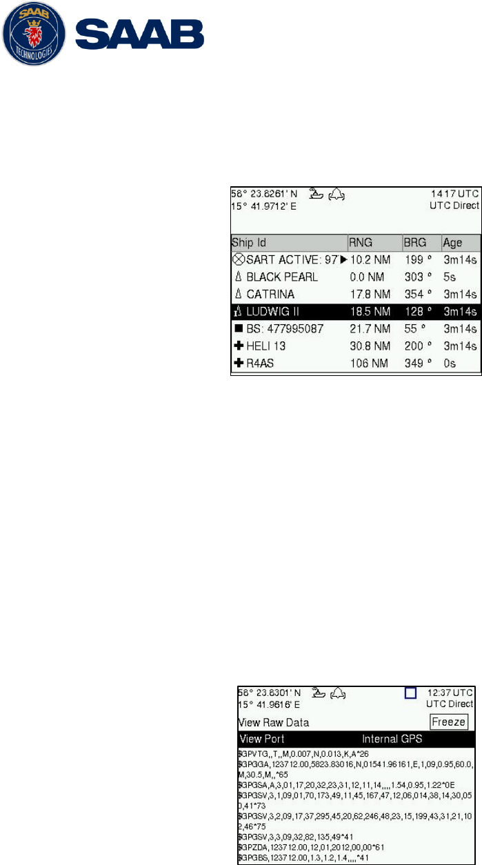
R5 SOLID AIS System
TROUBLESHOOTING
7000 118-200, A4 Page 59
7.4.2 Target list
The target list is primarily useful when analyzing the receiving functionality. The
propagation characteristics of VHF radio frequencies are close to line of sight. A harsh
radio environment, reflections in cables, connectors or the antenna will shorten the
effective range.
Figure 36 – Target List
7.4.3 Date and time
The date and time (UTC) in the upper right corner of the display is provided by the
transponder. If the date and time are not correct, the transponders internal GPS does
not have a position fix. This will also be indicated by the alarm “UTC sync invalid”. This
problem is normally caused by a GPS-antenna failure or damaged antenna cables.
This problem may also be caused by interference from radio equipment on-board.
7.4.4 View Raw data
The View Raw Data view can be used to see received data on the ports of the R5
SOLID. It is useful for troubleshooting to make sure that connected sensors provide
correct data to the R5 SOLID unit. The “View Port” parameter determines from which
port the data displayed in the view are taken. It is possible to pause the view by
pressing the “Freeze” button. All data that is received while the view is paused will not
be displayed in the view.
Figure 37 – View Raw Data
7.4.5 Status List
The status list view is used to display status indications that are stored in the
transponder. The indications are created when an important event has occurred in the
transponder. Time of occurrence and status indication text are shown in the view. A list
of all possible indications can be found in section 7.8 “Indication Messages”.
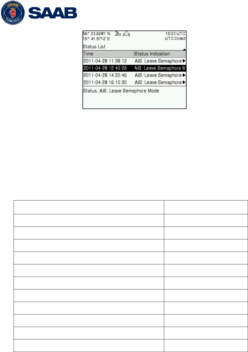
R5 SOLID AIS System
TROUBLESHOOTING
7000 118-200, A4 Page 60
Figure 38 – Status List
7.5 Reporting intervals for Class A transponders
The different information types are valid for different time periods and therefore they need
different update intervals. These update intervals are defined in the AIS standard (ITU-R
M 1371-3) and should be applied by all transponders. There are however some
exceptions from this, which can be found in the standard. Class B transponders have for
example different intervals than the Class A transponder.
All this needs to be taken in consideration while troubleshooting thus it affects the
anticipated behaviour of a transponder.
Information type / Condition
Nominal reporting interval
Static Information
6 min, on amendment, on request
Voyage related information
6 min, on amendment, on request
Dynamic information (See conditions below)
- Ship at anchor or moored and not moving faster than 3 knots
3 min
- Ship at anchor or moored and moving faster than 3 knots
10 sek
- Ship 0-14 knots
10 sek
- Ship 0-14 knots and changing course
3 1/3 sek
- Ship 14-23 knots
6 sek
- Ship 14-23 knots and changing course
2 sek
- Ship > 23 knots
2 sek
- Ship > 23 knots and changing course
2 sek
Table 13 – Reporting Intervals

R5 SOLID AIS System
TROUBLESHOOTING
7000 118-200, A4 Page 61
7.6 F.A.Q
7.6.1 I cannot see the vessel on the Internet AIS service
Websites providing AIS services like e.g. www.marinetraffic.com does not cover all the
seas of the world, but only specific coastal areas where AIS receivers have been
installed and that upload the data to the websites. The vessel must be in reception
range of these AIS receivers to show up on the Internet AIS service.
7.6.2 I can “see” the other vessel, but they do not “see” my vessel
There are several reasons why this might happen. The first thing to check is if the R5
SOLID is transmitting at all or if is transmitting in low power mode. In VHF Status view
described in section 4.24 it is possible to check the status on all R5 SOLID VHF
transceivers. Make sure that correct channels and power mode are used. There might
be a regional area set in the transponder that changes the operating mode of the R5
SOLID. Regional areas are listed in the Regional Area view (see section 4.17).
The MMSI must also be configured in order for the R5 SOLID to transmit. If the MMSI
is zero, the R5 SOLID will be silent.
Another possibility is that the other vessels‟ transponder requires a shorter reception
range in order to receive the R5 SOLID transmissions. In the Target List view and the
Plot view it is possible to see the range and bearing to other vessels.
7.6.3 The VHF range seems to be low
As a general rule, the VHF range is equal to line of sight from the antenna position,
which means that the higher the antenna is installed, the longer the range will be. It is
also important to follow the guide lines for an antenna installation as thorough as
possible. Section 3.5 describes how to best install the VHF antenna.
7.6.4 I can only receive a few GPS satellites
The position of the GPS antenna is of high importance to optimize the GPS reception.
Follow the guide lines of GPS antenna installation described in chapter 3.6 “Mount the
R5 SOLID GPS antenna” as thorough as possible.
If the ship is close to a harbour or shore with high structures or traveling in an area with
high terrain, the GPS reception might be lowered. The GPS antenna must be installed
where it has a clear view of the sky. The objective is to see the horizon freely through
360 degrees with a vertical observation of 5 to 90 degrees above the horizon.
The GPS antenna cable should also be as short as possible and with 50 Ω impedance.
A very long antenna cable or faulty impedance can heavily reduce the GPS reception.
7.7 Contacting Support
The primary source for support and RMA issues should for end customers be the local
dealer where the equipment was purchased in the first place. Another option is to contact
one of our OEM partners or affiliate service stations and request help. An updated list with
our dealers, OEM partners and service stations can be found at our website, listed under
the corresponding product. www.saabgroup.com/transponder
It is also possible to contact Saab TransponderTech‟s technical support if this is preferred.
We recommend contacting us via email at support.transpondetech@saabgroup.com for
most accurate and detailed help. If the situation is very urgent then it is of course also
possible to call us at normal Swedish workdays and working hours (UTC +1h/+2h).
Telephone +46-13-189420.

R5 SOLID AIS System
TROUBLESHOOTING
7000 118-200, A4 Page 62
Before contacting support, always check the following information and include it in the first
email, or have it ready at the phone call:
- All the information provided by the SW/HW Info view which can be accessed from
Main Menu
Status
SW/HW Info.
- Detailed fault description
7.8 Indication Messages
The indication messages, with identity and type information, are listed below:
ID Type Message text
021 Status External DGNSS in use
022 Status External GNSS in use
023 Status Internal DGNSS in use (beacon)
024 Status Internal DGNSS in use (msg 17)
025 Status Internal GNSS in use
027 Status External SOG/COG in use
028 Status Internal SOG/COG in use
031 Status Heading valid
033 Status Rate of Turn Indicator in use
034 Status Other ROT source in use
036 Event Channel management parameters changed
056 Event Channel management zone memory changed
061 Status Enter semaphore mode
062 Event Leave semaphore mode
063 Event NVM Checksum errors
064 Event RATDMA overflow
066 Status Tanker Low VHF Power Mode
067 Status Beacon correction received
068 Status VDL correction received
069 Status No correction received
7.9 Long Range Definitions
A = Ship‟s name, call sign, and IMO number
B = Date and time of message composition
C = Position
E = Course over ground (COG)
F = Speed over ground (SOG)
I = Destination and Estimated Time of Arrival (ETA)
O = Draught
P = Ship/Cargo
U = Ship‟s length, breadth, type
W= Persons on board
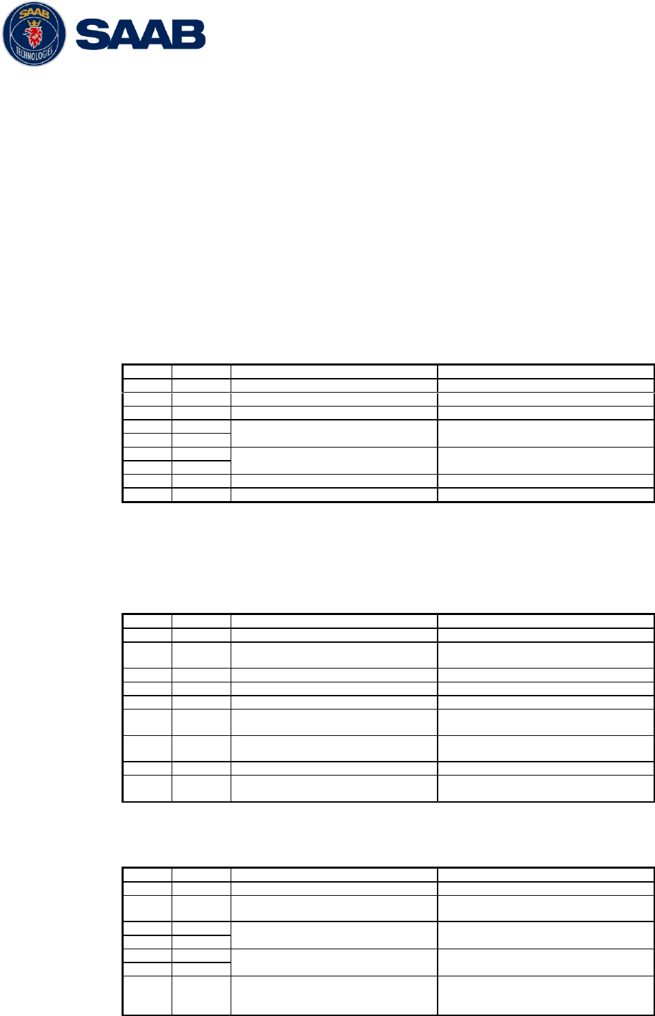
R5 SOLID AIS System
INTERPRETATION OF INPUT SENTENCES
7000 118-200, A4 Page 63
8 INTERPRETATION OF INPUT SENTENCES
All interface ports accepts the full set of input listed below sentences, except the
sentences listed in section 8.4.1 that is unique to the Long Range interface port.
The protocol of the serial input sentences shall be compliant to IEC 61162-1Ed.4 (2010-
11) for maximum interoperability.
8.1 GPS and Sensor Input Sentences
8.1.1 DTM - Datum Reference
If local code is other than WGS84, then the positions report from that
port is discarded.
$--DTM,ccc,a,x.x,a,x.x,a,x.x,ccc
Field
Format
Name
Comment
1
--DTM
Sentence Id
Used
2
ccc
Local Datum Code
Interpret if it‟s WGS84 or not
3
A
Local Datum Subdivision Code
Ignored
4
x.x
Lat Offset (2 fields)
Ignored
Ignored
5
a
6
x.x
Long Offset (2 fields)
Ignored
Ignored
7
a
8
x.x
Altitude Offset
Ignored
9
ccc
Reference Datum Code
Ignored
8.1.2 GBS - GNSS Satellite Fault Detection
If this sentence is received once a second from the position source in
use, the RAIM flag will be set to TRUE.
$--GBS,hhmmss.ss,x.x,x.x,x.x,xx,x.x,x.x,x.x
Field
Format
Name
Comment
1
--GBS
Sentence Id
Used
2
hhmmss.
ss
UTC Time of GGA or GNS
Ignored
3
x.x
Expected Error in latitude
Used
4
x.x
Expected Error in longitude
Used
5
x.x
Expected error in altitude
Ignored
6
xx
ID number of most likely
failed satellite
Ignored
7
x.x
Probability of missed
detection
Ignored
8
x.x
Estimate of bias in meters
Ignored
9
x.x
Standard Deviation of bias
estimate
Ignored
8.1.3 GGA - Global Positioning System Fix Data
$--GGA,hhmmss.ss,llll.ll,a,yyyy.yy,a,x,xx,x.x,x.x,M,x.x,M,x.x,xxxx
Field
Format
Name
Comment
1
--GGA
Sentence Id
Used
2
hhmmss.
ss
UTC of position
UTC Second is used to indicate
Time Stamp
3
llll.ll
Latitude
Used
4
a
5
yyyy.yy
Longitude
Used
6
a
7
x
GPS quality indicator
Used,
1 -> Position with Low Accuracy
2 -> Position with High

R5 SOLID AIS System
INTERPRETATION OF INPUT SENTENCES
7000 118-200, A4 Page 64
Accuracy
3 -> Position with Low Accuracy
6 -> Dead Reckoning with Low
Accuracy
7 -> Manual mode with low
accuracy
OTHER -> No Position
Used when the GPS is the
internal GPS (Used in
proprietary sentences)
8
xx
Satellites in use
Ignored
9
x.x
Horizontal dilution of
precision
Ignored
10
x.x
Antenna altitude
Ignored
11
M
Units of antenna altitude,
meter
Ignored
12
x.x
Geodial separation
Ignored
13
M
Units of geodial sep.
Ignored
14
x.x
Age of differential GPS data
Ignored
15
xxxx
Differential reference
station ID
Ignored
8.1.4 GLL – Geographic position, latitude/longitude
$--GLL,llll.ll,a,yyyy.yy,a,hhmmss.ss,A,a
Field
Format
Name
Comment
1
--GLL
Sentence Id
Used
2
llll.ll
Latitude
Used
3
a
4
yyyy.yy
Longitude
Used
5
a
6
hhmmss.
ss
UTC of position
UTC Second is used to indicate
Time Stamp
7
A
Status
Used
8
a
Mode indicator
NULL -> Message is ignored
A -> Position with Low Accuracy
D -> Position with High
Accuracy
E -> Dead Reckoning Mode with
Low Accuracy
M-> Manual Mode with Low
Accuracy
OTHER -> No Position
8.1.5 GNS – GNSS fix data
If the Mode Indicator is a NULL field, the sentence is ignored.
$--GNS,hhmmss.ss,llll.ll,a,yyyy.yy,a,c--c,xx,x.x,x.x,x.x,x.x,x.x
Field
Format
Name
Comment
1
--GLL
Sentence Id
Used
2
hhmmss.
ss
UTC of position
UTC Second is used to indicate
Time Stamp
3
llll.ll
Latitude
Used
4
a
5
yyyy.yy
Longitude
Used
6
a
7
c--c
Mode indicator
A, P -> Position with low
accuracy
D, R, F -> Position with high
Accuracy
E -> Dead Reckoning Mode with
Low accuracy
M -> Manual Mode with low
accuracy
OTHER -> No Position
8
xx
Total number of satellites
Used when the GPS source is the
internal GPS (used in
proprietary sentences)
R5 SOLID AIS System
INTERPRETATION OF INPUT SENTENCES
7000 118-200, A4 Page 65
9
x.x
HDOP
Ignored
10
x.x
Antenna altitude, meter
Ignored
11
x.x
Geodial separation
Ignored
12
x.x
Age of differential
corrections
Ignored
13
x.x
Differential reference
station ID
Ignored
8.1.6 HDT - Heading, True
The use of this sentence is talker identifier dependent.
$--HDT,x.x,T
Field
Format
Name
Comment
1
--HDG
Sentence Id
Used
2
x.x
Heading, degrees true
Used
3
T
NOTE: HDT input must be sent at least every 3 seconds for
the R5 SOLID to calculate ROT from the HDT input.
8.1.7 OSD – Own ship data
$--OSD,x.x,A,x.x,a,x.x,a,x.x,x.x,a
Field
Format
Name
Comment
1
--OSD
Sentence Id
Used
2
x.x
Heading, degrees true
Used if heading status is „A‟
3
A
Heading status
Used
4
x.x
Vessel course, degrees true
Used as COG
5
a
Course reference
Used1
6
x.x
Vessel speed
Used as SOG
7
a
Speed reference
Used1
8
x.x
Vessel set
Ignored
9
x.x
Vessel drift
Ignored
10
a
Speed units
Used to convert SOG to knots
8.1.8 RMC – Recommended minimum specific GNSS data
$--RMC,hhmmss.ss,A,llll.ll,a,yyyy.yy,a,x.x,x.x,xxxxxx,x.x,a,a
Field
Format
Name
Comment
1
--RMC
Sentence Id
Used
2
hhmmss.
ss
UTC of position
UTC Second is used to indicate
Time Stamp
3
A
Status
Used
4
llll.ll
Latitude
Used
5
a
6
yyyy.yy
Longitude
Used
7
a
8
x.x
Speed over ground, knots
Used
9
x.x
Course over ground, degrees
true
Used
10
xxxxxx
Date
Ignored
11
x.x
Magnetic variation
Ignored
12
a
13
a
Mode indicator
NULL -> Message is ignored
A -> Position with low accuracy
D -> Position with high
accuracy
E -> Dead Reckoning Mode with
Low accuracy
M -> Manual Mode with low
accuracy
OTHER -> No Position
1
SOG and COG are used if both COG reference and SOG reference are set to either: B, P, R
R5 SOLID AIS System
INTERPRETATION OF INPUT SENTENCES
7000 118-200, A4 Page 66
8.1.9 ROT – Rate of turn
The rate of turn value is only used if the talker identifier is TI.
Otherwise the value will only be used to determine the direction, i.e.
”Moving Right” or ”Moving Left”.
$--ROT,x.x,A
Field
Format
Name
Comment
1
--ROT
Sentence Id
Used
2
x.x
Rate of turn
Used if Status is set to „A‟
3
A
Status
Used
8.1.10 VBW - Dual Ground / Water Speed
The current position source must be external GPS, and heading must
be available for the transponder to accept this sentence.
$--VBW,x.x,x.x,A,x.x,x.x,A,x.x,A,x.x,A
Field
Format
Name
Comment
1
--ROT
Sentence Id
Used
2
x.x
Longitudinal water speed
Ignored
3
x.x
Transverse water speed
Ignored
4
A
Status: water speed
Ignored
5
x.x
Longitudinal ground speed
Used if Status is set to A
6
x.x
Transverse ground speed
Used if Status is set to A
7
A
Status: ground speed
Used
8
x.x
Stern transverse water speed
Ignored
9
A
Status stern water speed
Ignored
10
x.x
Stern transverse ground speed
Ignored
11
A
Status stern ground speed
Ignored
8.1.11 VTG – Course over ground and ground speed
$--VTG,x.x,T,x.x,M,x.x,N,x.x,K,a
Field
Format
Name
Comment
1
--VTG
Sentence Id
Used
2
x.x
Course over ground, degrees
true
Used
3
T
4
x.x
Course over ground, degrees
magnetic
Ignored
5
M
6
x.x
Speed over ground, knots
Used
7
N
8
x.x
Speed over ground, km/h
Ignored
9
K
10
a
Mode indicator
Used
8.1.12 ZDA – Time and date
This message is only interpreted if it’s received from the internal GPS
(the time synchronisation source).
$--ZDA,hhmmss.ss,xx,xx,xxxx,xx,xx
Field
Format
Name
Comment
1
--ZDA
Sentence Id
Used
2
hhmmss.
ss
UTC
Used
3
xx
Day (UTC)
Used
4
xx
Month (UTC)
Used
5
xxxx
Year (UTC)
Used
6
xx
Local zone hours
Ignored
7
xx
Local zone minutes
Ignored
R5 SOLID AIS System
INTERPRETATION OF INPUT SENTENCES
7000 118-200, A4 Page 67
8.2 General Input Sentences
8.2.1 ACK – Acknowledge Alarm
$--ACK,xxx
Field
Format
Name
Comment
1
--ACK
Sentence Id
Used
2
xxx
ID of the alarm source
Used
8.2.2 EPV – Command or report equipment property value
$--EPV,a,c--c,c--c,x.x,c--c,
Field
Format
Name
Comment
1
--EPV
Sentence Id
Used
2
a
Sentence status flag
Used
3
c--c
Destination equipment type
Used, AI or STT
4
c--c
Unique Identifier
Used, may be null
5
x.x
Property identifier
Used
6
c--c
Value of property to be set
Used
8.2.1 SPW – Security Password Sentence
$--SPW,ccc,c--c,x,c--c
Field
Format
Name
Comment
1
--SPW
Sentence Id
Used
2
ccc
Password protected sentece
Used
3
c--c
Unique Identifier
Used, may be NULL
4
x
Password level
Used
5
c--c
Password
Used
8.2.1 HBT – Heartbeat Supervision Sentence
$--HBT,x.x,A,x
Field
Format
Name
Comment
1
--SPW
Sentence Id
Used
2
x.x
Configured repeat interval
Used (Limited to 60 sec)
3
A
Equipment status
Used
4
x
Sequential sentence
identifier
Ignored
8.3 AIS Specific Input Sentences
8.3.1 ABM – Addressed Binary and Safety-Related Message
!--ABM,x,x,x,xxxxxxxxx,x,x.x,s--s,x
Field
Format
Name
Comment
1
--ABM
Sentence Id
Used
2
x
Total nr of sentences
Used if in interval 1..9,
otherwise the sentence is
ignored
3
x
Sentence number
Used if in interval 1..total
sentences, otherwise the
sentence is ignored
4
x
Sequential message identifier
Used if in interval 0..3,
otherwise the sentence is
ignored
5
xxxxxxx
xxx
MMSI of Destination
Used
6
X
AIS Channel
Used
7
x.x
Message Id
Used if 6 or 12, otherwise the
sentence is ignored
8
s--s
Encapsulated Data
Used
9
x
Number of filled bits
Used
R5 SOLID AIS System
INTERPRETATION OF INPUT SENTENCES
7000 118-200, A4 Page 68
8.3.2 ACA – AIS Regional Channel Assignment Message
The zone created of this sentence must be accepted by the channel
management rules (size of zone, distance to own position, valid
channel number etc). If the zone isn’t accepted, the zone will be
ignored.
$--ACA,x,llll.ll,a,yyyy.yy,a,llll.ll,a,yyyy.yy,a,x,xxxx,x,xxxx,x,x,x,a,x,
hhmmss.ss
Field
Format
Name
Comment
1
--ACA
Sentence Id
Used
2
x
Sequence number
Ignored
3
llll.ll
NE latitude (2 fields)
Used
4
a
5
yyyy.yy
NE longitude (2 fields)
Used
6
a
7
llll.ll
SW latitude (2 fields)
Used
8
a
9
yyyy.yy
SW longitude (2 fields)
Used
10
a
11
x
Transitional zone size
Used
12
xxxx
Channel A
Used
13
x
Channel A bandwidth
Used
14
xxxx
Channel B
Used
15
x
Channel B bandwidth
Used
16
x
Tx/Rx mode
Used
17
x
Power level
Used
18
a
Information source
Ignored
19
x
In use flag
Ignored
20
hhmmss.
ss
Time of In use change
Ignored
8.3.3 AIQ – Query Sentence
$--AIQ,ccc
Field
Format
Name
Comment
1
--
Talker ID of requester
Used
2
AIQ
Talker ID for device
Used
3
ccc
Approved sentence formatter
of data being requested
It‟s possible to query the
following sentences:
ACA, ALR, EPV, LRI, SSD, TRL,
TXT and VSD
8.3.4 AIR – AIS Interrogation Request
This sentence can also be used to do a “UTC Request”. It’s always
sent on both Channel A and Channel B (due to that this is a multiple
addressed sentence).
$--AIR,xxxxxxxxx,x.x,x,x.x,x,xxxxxxxxx,x.x,x
Field
Format
Name
Comment
1
--AIR
Sentence Id
Used
2
xxxxxxx
xx
MMSI 1
Used
3
x.x
Message ID 1.1
Used
4
x
Message sub section
Ignored
5
x.x
Message ID 1.2
Used, may be NULL
6
x
Message sub section
Ignored
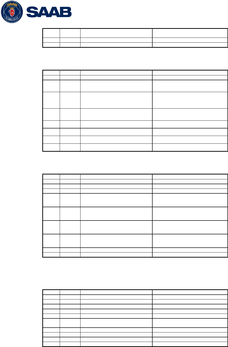
R5 SOLID AIS System
INTERPRETATION OF INPUT SENTENCES
7000 118-200, A4 Page 69
7
xxxxxxx
xx
MMSI 2
Used, may be NULL
8
x.x
Message ID 2.1
Used, may be NULL
9
X
Message sub section
Ignored
8.3.5 BBM – Broadcast Binary Message
$--BBM,x,x,x,x,x.x,s--s,x
Field
Format
Name
Comment
1
--BBM
Sentence Id
Used
2
X
Total number of sentences
Used if in interval 1..9,
otherwise rejected
3
X
Sentence number
Used if in interval 1..total
number of sentences, otherwise
rejected.
4
X
Sequential message identifier
Used if in interval 0..9,
otherwise rejected
5
X
AIS channel
Used
6
x.x
Message Id
Used if 8 or 14
7
s—s
Encapsulated data
Used
8
X
Number of filled bits
Used
8.3.6 SSD – Ship Static Data
$--SSD,c--c,c--c,xxx,xxx,xx,xx,c,aa
Field
Format
Name
Comment
1
--SSD
Sentence Id
Used
2
c--c
Call sign
Used, may be NULL
3
c--c
Name
Used, may be NULL
4
xxx
Pos ref A
Used to change position
reference for the position
source in use. May be NULL.
5
xxx
Pos ref B
Used to change position
reference for the position
source in use. May be NULL.
6
xx
Pos ref C
Used to change position
reference for the position
source in use. May be NULL.
7
xx
Pos ref D
Used to change position
reference for the position
source in use. May be NULL.
8
c
DTE
Ignored
9
aa
Source identifier
Used
8.3.7 VSD – Voyage Static Data
$--VSD,x.x,x.x,x.x,c--c,hhmmss.ss,xx,xx,x.x,x.x
Field
Format
Name
Comment
1
--VSD
Sentence Id
Used
2
x.x
Type of ship and cargo
Used
3
x.x
Maximum present draught
Used
4
x.x
Persons on-board
Used
5
c--c
Destination
Used
6
hhmmss.
ss
Est. UTC of arrival
Used
7
Xx
Est. day of arrival
Used
8
Xx
Est. month of arrival
Used
9
x.x
Navigational status
Used
10
x.x
Regional application flags
Used
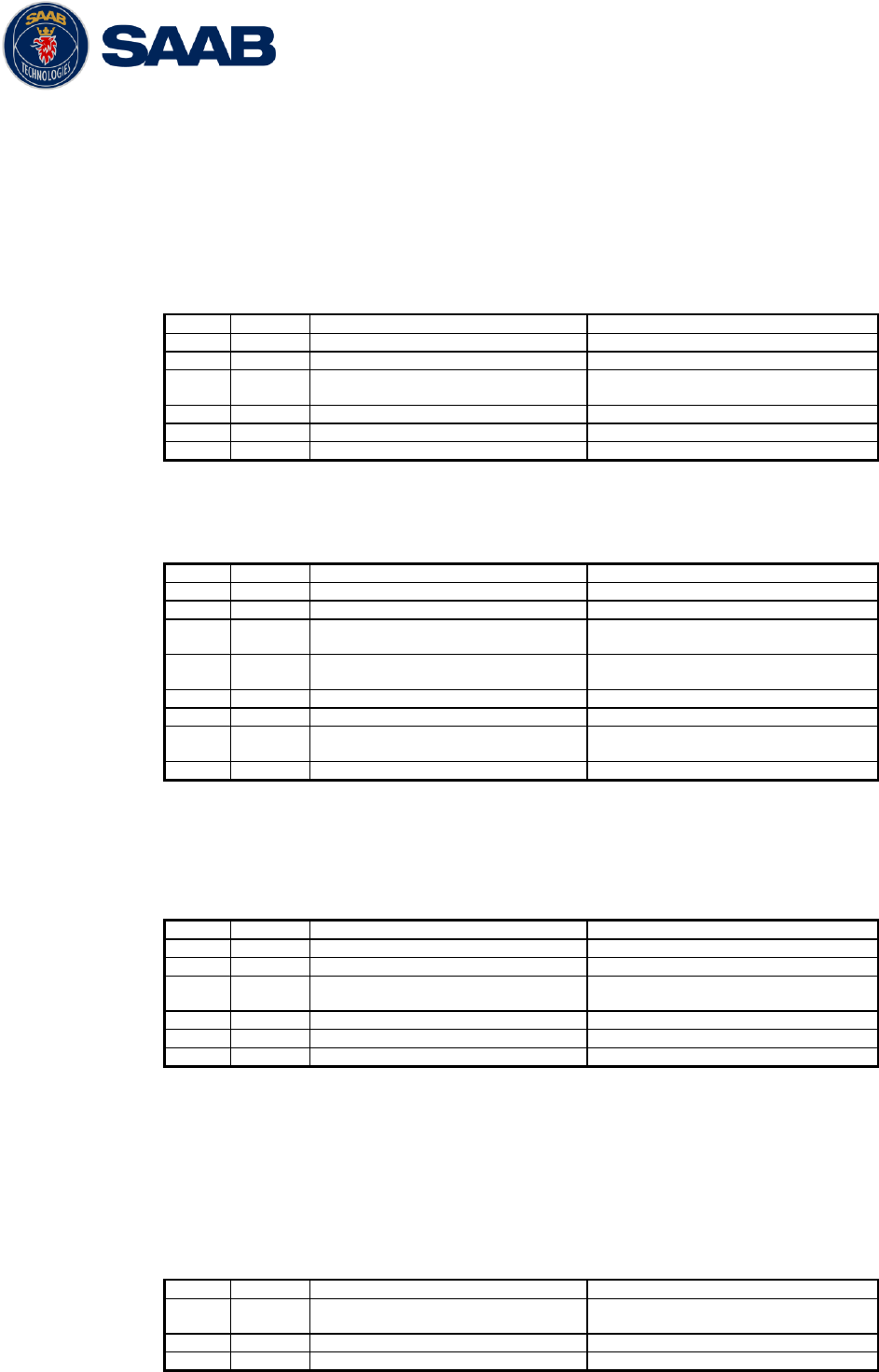
R5 SOLID AIS System
INTERPRETATION OF INPUT SENTENCES
7000 118-200, A4 Page 70
8.4 Long range input sentences
8.4.1 On Long range port
The LR sentences can only be used with the Long Range interface port.
8.4.1.1 LRF – AIS long-range function
$--LRF,x,xxxxxxxxx,c—c,c—c,c—c
Field
Format
Name
Comment
1
--LRF
Sentence Id
Used
2
x
Sequence number
Used
3
xxxxxxx
xx
MMSI of requestor
Used
4
c--c
Name of requestor
Used
5
c--c
Function request
Used
6
c--c
Function reply status
Used
8.4.1.2 LRI – AIS long-range interrogation
$--LRI,x,a,xxxxxxxxx,xxxxxxxxx,llll.ll,a,yyyyy.yy,a,llll.ll,a,yyyyy.yy,a
Field
Format
Name
Comment
1
--LRI
Sentence Id
Used
2
x
Sequence number
Used
3
xxxxxxx
xx
MMSI of requestor
Used
4
xxxxxxx
x
MMSI of destination
Used
5
llll.ll
Latitude
Used
6
a
N / S
Used
7
yyyyy.y
y
Longitude
Used
8
a
E / W
Used
8.4.2 On other input ports
8.4.2.1 LRF – AIS long-range function
$--LRF,x,xxxxxxxxx,c—c,c—c,c—c
Field
Format
Name
Comment
1
--LRF
Sentence Id
Used
2
x
Sequence number
Used
3
xxxxxxx
xx
MMSI of requestor
Used
4
c--c
Name of requestor
Used
5
c--c
Function request
Used
6
c--c
Function reply status
Used
8.5 Proprietary Input Sentences
All Saab TransponderTech Proprietary Sentences will have talker ID PSTT.
8.5.1 Proprietary Query message PSTT,101
$PSTT,101,c--c,
Field
Format
Name
Comment
1
PSTT
Proprietary SAAB
TranspondeTech Sentence
Used
2
101
Sentence Query
Used
3
c--c
Proprietary sentence to query
Used
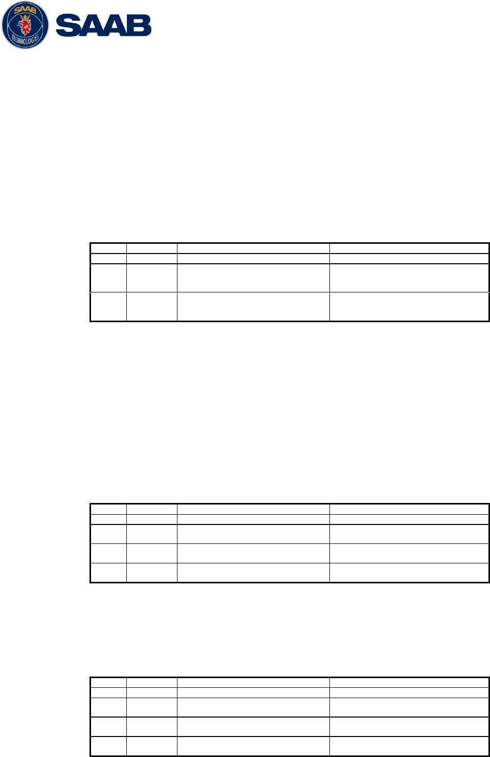
R5 SOLID AIS System
INTERPRETATION OF OUTPUT SENTENCES
7000 118-200, A4 Page 71
9 INTERPRETATION OF OUTPUT SENTENCES
9.1 Proprietary Output Sentences (PSTT)
In addition to the standardized IEC sentences, the R5 SOLID is able to output the
proprietary sentences listed below. All Saab TransponderTech Proprietary Sentences will
have talker ID “PSTT”.
9.1.1 $PSTT,10A – UTC Date and Time
This sentence provides UTC Date and Time, i.e. R5 SOLID system time (based on
internal GNSS time). It is output approximately once every 10 seconds (± 1 s).
$PSTT,10A,YYYYMMDD,HHMMSS
Field
Format
Name
Comment
1
10A
Sentence Id
10A always
2
YYYYMMDD
Date
Year, month and day in decimal
notation.
(00000000 = Not available)
3
HHMMSS
Time
Hour, minute and second in
decimal notation.
(999999 = Not available)
Example: $PSTT,10A,20121028,135230*<FCS><CR><LF>
= Date October 28, 2012
= Time 13:52:30 UTC
9.1.2 $PSTT,10C – Data Link Status
This sentence provides information about the traffic on the VHF data link. It is output
approximately once every 60 seconds. Traffic load is calculated over the last frame (i.e.
60 seconds). Number of units is derived from the internal user list and is generally the
number of received units within the last few minutes.
$PSTT,10C,C,LLL,NNNN
Field
Format
Name
Comment
1
10C
Sentence Id
10C always
2
C
Channel
A = VDL Channel A
B = VDL Channel B
3
LLL
Traffic Load
Data link traffic load in
precent, 0-100.
4
NNNN
Number of Units
Number of units occupying the
data link
9.1.3 $PSTT,146 – System Operational Mode Status
This sentence reports the system operational mode. This sentence is output on
change, periodically every minute and on request using PSTT,101.
$PSTT,146,x,x,x*hh<CR><LF>
Field
Format
Name
Comment
1
146
Sentence Id
146 always
2
X
1 W Mode
0 = Default
1 = 1 Watt
3
X
System Mode
0 = Class A
1 = Inland
4
X
Transmit mode
0 = Normal
1 = Silent
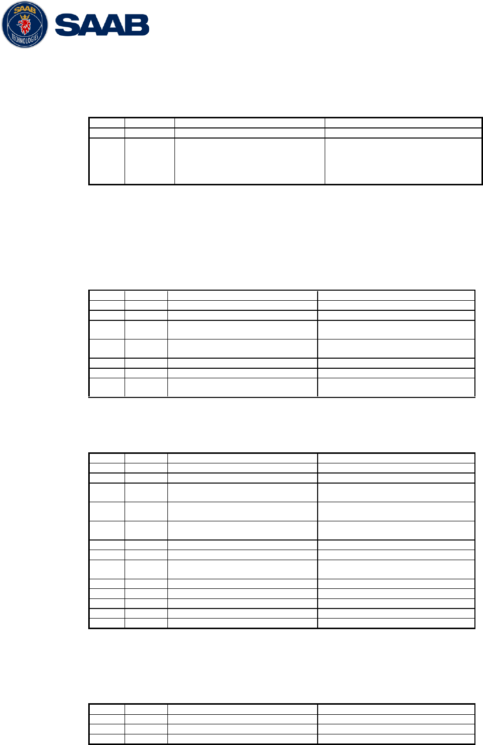
R5 SOLID AIS System
INTERPRETATION OF OUTPUT SENTENCES
7000 118-200, A4 Page 72
9.1.4 $PSTT,1F3 – Transponder Restart
This sentence will be output when the transponder has restarted.
$PSTT,1F3,R
Field
Format
Name
Comment
1
1F3
Sentence Id
1F3 always
2
R
Restart Reason
0 = Unknown
1 = Cold Start
2 = General Protection Fault
3 = Power Fail
4 = Warm Start
9.2 Long range output sentences
9.2.1 On Long range port
9.2.1.1 LR1 – AIS long-range reply sentence 1
$--LR1,x,xxxxxxxxx,xxxxxxxxx,c—c,c—c,xxxxxxxxx
Field
Format
Name
Comment
1
--LR1
Sentence Id
Used
2
x
Sequence number
Used
3
xxxxxxx
xx
MMSI of responder
Used
4
xxxxxxx
xx
MMSI of requestor (reply
destination
Used
5
c--c
Ship‟s name
Used
6
c--c
Call sign
Used
7
xxxxxxx
xx
IMO Number
Used
9.2.1.2 LR2 – AIS long-range reply sentence 2
$--LR2,x,xxxxxxxxx,xxxxxxxx,hhmmss.ss,llll.ll,a,yyyyy.yy,a,x.x,T,x.x,N
Field
Format
Name
Comment
1
--LR2
Sentence Id
Used
2
x
Sequence number
Used
3
xxxxxxx
xx
MMSI of responder
Used
4
xxxxxxx
x
Date
Used
5
hhmmss.
ss
UTC time of position
Used
6
llll.ll
Latitude
Used
7
a
N / S
Used
8
yyyyy.y
y
Longitude
Used
9
a
E / W
Used
10
x.x
Course over ground
Used
11
T
Validity of COG
Used
12
x.x
Speed over ground
Used
13
N
Validity of SOG
Used
9.2.1.3 LR3 – AIS long-range reply sentence 3
$--LR3,x,xxxxxxxxx,c—c,xxxxxx,hhmmss.ss,x.x,x.x,x.x,x.x,x.x,x.x
Output rate: On event
Field
Format
Name
Comment
1
--LR3
Sentence Id
Used
2
x
Sequence number
Used
3
xxxxxxx
MMSI of responder
Used
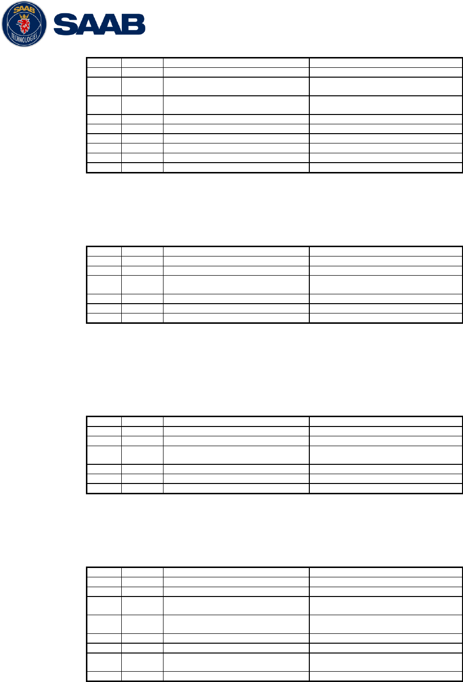
R5 SOLID AIS System
INTERPRETATION OF OUTPUT SENTENCES
7000 118-200, A4 Page 73
xx
4
c--c
Voyage destination
Used
5
xxxxxxx
x
ETA Date
Used
6
hhmmss.
ss
ETA time
Used
7
x.x
Draught
Used
8
x.x
Ship / Cargo
Used
9
x.x
Ship length
Used
10
x.x
Ship width
Used
11
x.x
Ship type
Used
12
x.x
Persons
Used
9.2.1.4 LRF – AIS long-range function
$--LRF,x,xxxxxxxxx,c—c,c—c,c—c
Output rate: On event
Field
Format
Name
Comment
1
--LRF
Sentence Id
Used
2
x
Sequence number
Used
3
xxxxxxx
xx
MMSI of requestor
Used
4
c--c
Name of requestor
Used
5
c--c
Function request
Used
6
c--c
Function reply status
Used
9.2.2 On all other output ports
9.2.2.1 LRF – AIS long-range function
$--LRF,x,xxxxxxxxx,c—c,c—c,c—c
Output rate: On event
Field
Format
Name
Comment
1
--LRF
Sentence Id
Used
2
x
Sequence number
Used
3
xxxxxxx
xx
MMSI of requestor
Used
4
c--c
Name of requestor
Used
5
c--c
Function request
Used
6
c--c
Function reply status
Used
9.2.2.2 LRI – AIS long-range interrogation
$--LRI,x,a,xxxxxxxxx,xxxxxxxxx,llll.ll,a,yyyyy.yy,a,llll.ll,a,yyyyy.yy,a
Output rate: On event
Field
Format
Name
Comment
1
--LRI
Sentence Id
Used
2
x
Sequence number
Used
3
xxxxxxx
xx
MMSI of requestor
Used
4
xxxxxxx
x
MMSI of destination
Used
5
llll.ll
Latitude
Used
6
a
N / S
Used
7
yyyyy.y
y
Longitude
Used
8
a
E / W
Used
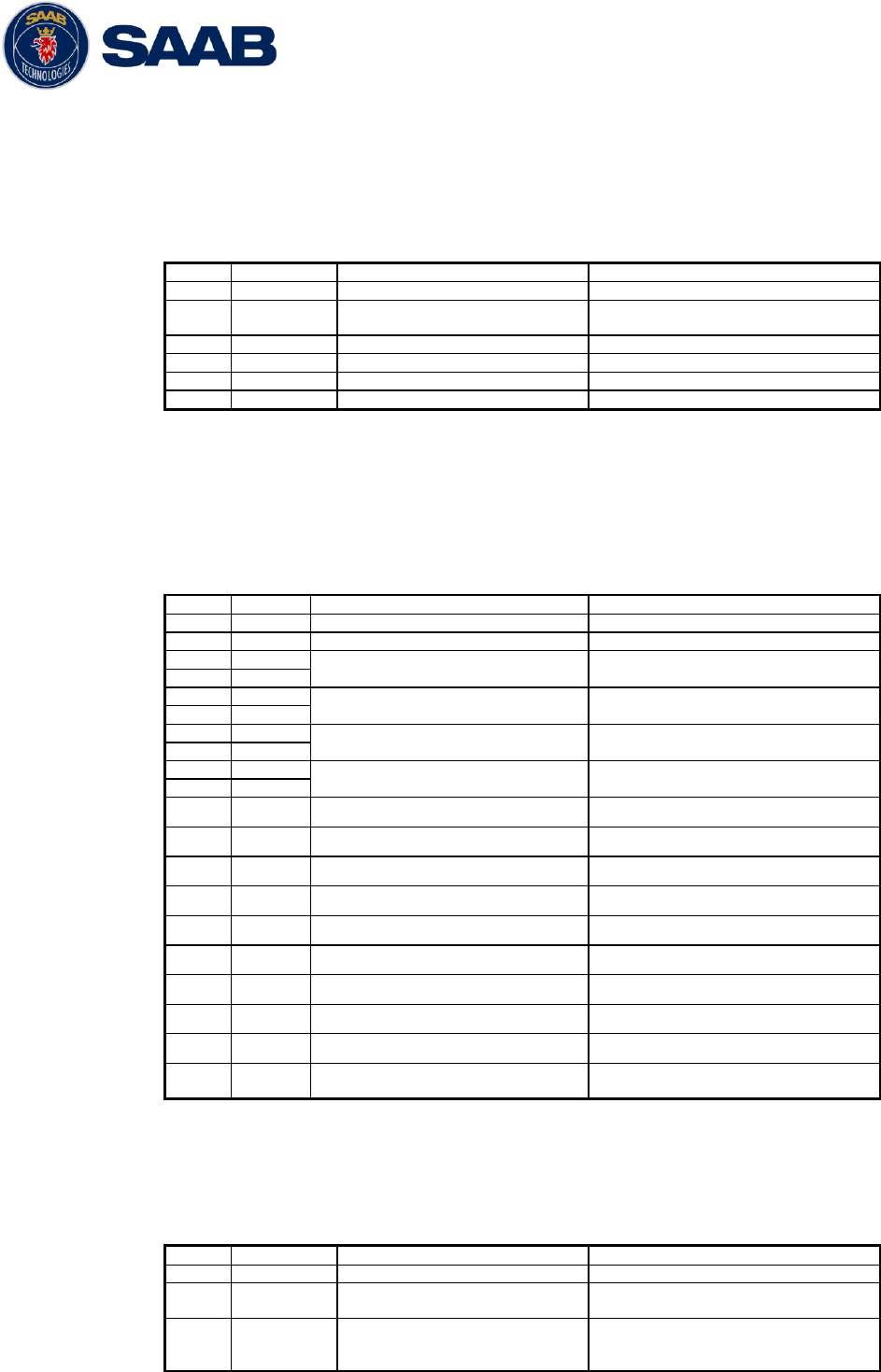
R5 SOLID AIS System
INTERPRETATION OF OUTPUT SENTENCES
7000 118-200, A4 Page 74
9.3 AIS output sentences
9.3.1 ABK – AIS Addressed and binary broadcast acknowledgement
$ -- ABK,xxxxxxxxx,x,x.x,x,x
Output rate: On event.
Field
Format
Name
Comment
1
--ABK
Sentence Id
Used
2
xxxxxxxxx
MMSI of the addressed AIS
unit
Used
3
x
AIS channel of reception
Used
4
x.x
ITU - R M.1371 Message ID
Used
5
x
Message sequence number
Used
6
x
Type of acknowledgement
Used
9.3.2 ACA – AIS Regional Channel Assignment Message
$--ACA,x,llll.ll,a,yyyy.yy,a,llll.ll,a,yyyy.yy,a,x,xxxx,x,xxxx,x,x,x,a,x,
hhmmss.ss
Output rate: On event. On request.
Field
Format
Name
Comment
1
--ACA
Sentence Id
Used
2
x
Sequence number
Ignored
3
llll.ll
NE latitude (2 fields)
Used
4
a
5
yyyy.yy
NE longitude (2 fields)
Used
6
a
7
llll.ll
SW latitude (2 fields)
Used
8
a
9
yyyy.yy
SW longitude (2 fields)
Used
10
a
11
x
Transitional zone size
Used
12
xxxx
Channel A
Used
13
x
Channel A bandwidth
Used
14
xxxx
Channel B
Used
15
x
Channel B bandwidth
Used
16
x
Tx/Rx mode
Used
17
x
Power level
Used
18
a
Information source
Ignored
19
x
In use flag
Ignored
20
hhmmss.
ss
Time of In use change
Ignored
9.3.3 ALR – Set alarm state
$--ALR,hhmmss.ss,xxx,A, A,c--c
Output rate: On event, on request, and automatically. Output every
30s for active alarms and every 60s when no active alarms.
Field
Format
Name
Comment
1
--ALR
Sentence Id
Used
2
hhmmss.ss
Time of alarm condition
change, UTC
Used
3
Xxx
Unique alarm number
(identifier) at alarm
source
Used
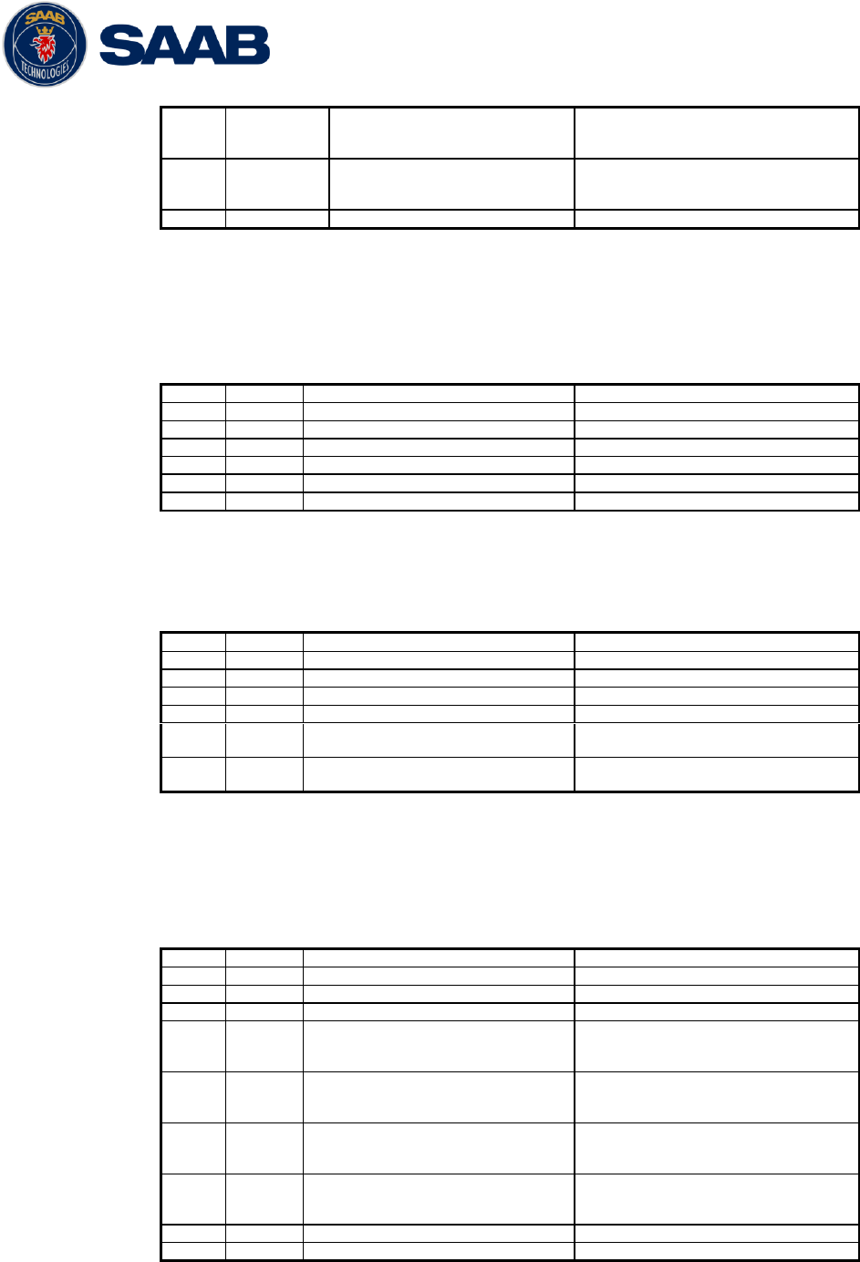
R5 SOLID AIS System
INTERPRETATION OF OUTPUT SENTENCES
7000 118-200, A4 Page 75
4
A
Alarm condition
A = threshold exceeded
V = not exceeded
Used
5
A
Alarm‟s acknowledge state
A = acknowledged
V = unacknowledged
Used
6
c--c
Alarm‟s description text
Used
9.3.4 EPV – Command or report equipment property value
$--EPV,a,c--c,c--c,x.x,c—c
Output rate: On request.
Field
Format
Name
Comment
1
--EPV
Sentence Id
Used
2
a
Sentence status flag
Used
3
c--c
Destination equipment type
Used
4
c--c
Unique Identifier
Used
5
x.x
Property identifier
Used
6
c--c
Value of property
Used
9.3.5 NAK – Negative acknowledgement
$--NAK,cc,ccc,c--c,x.x,c—c
Output rate: On event
Field
Format
Name
Comment
1
--NAK
Sentence Id
Used
2
cc
Talker identifier
Used
3
ccc
Affected sentence formatter
Used
4
c--c
Unique Identifier
Used
5
x.x
Reason code for negative
acknowledgement
Used
6
c--c
Negative acknowledgement‟s
descriptive text
Used
9.3.6 SSD – Ship Static Data
$--SSD,c--c,c--c,xxx,xxx,xx,xx,c,aa
Output rate: On request.
Field
Format
Name
Comment
1
--SSD
Sentence Id
Used
2
c--c
Call sign
Used, may be NULL
3
c--c
Name
Used, may be NULL
4
xxx
Pos ref A
Used to change position
reference for the position
source in use. May be NULL.
5
xxx
Pos ref B
Used to change position
reference for the position
source in use. May be NULL.
6
xx
Pos ref C
Used to change position
reference for the position
source in use. May be NULL.
7
xx
Pos ref D
Used to change position
reference for the position
source in use. May be NULL.
8
c
DTE
Ignored
9
aa
Source identifier
Ignored
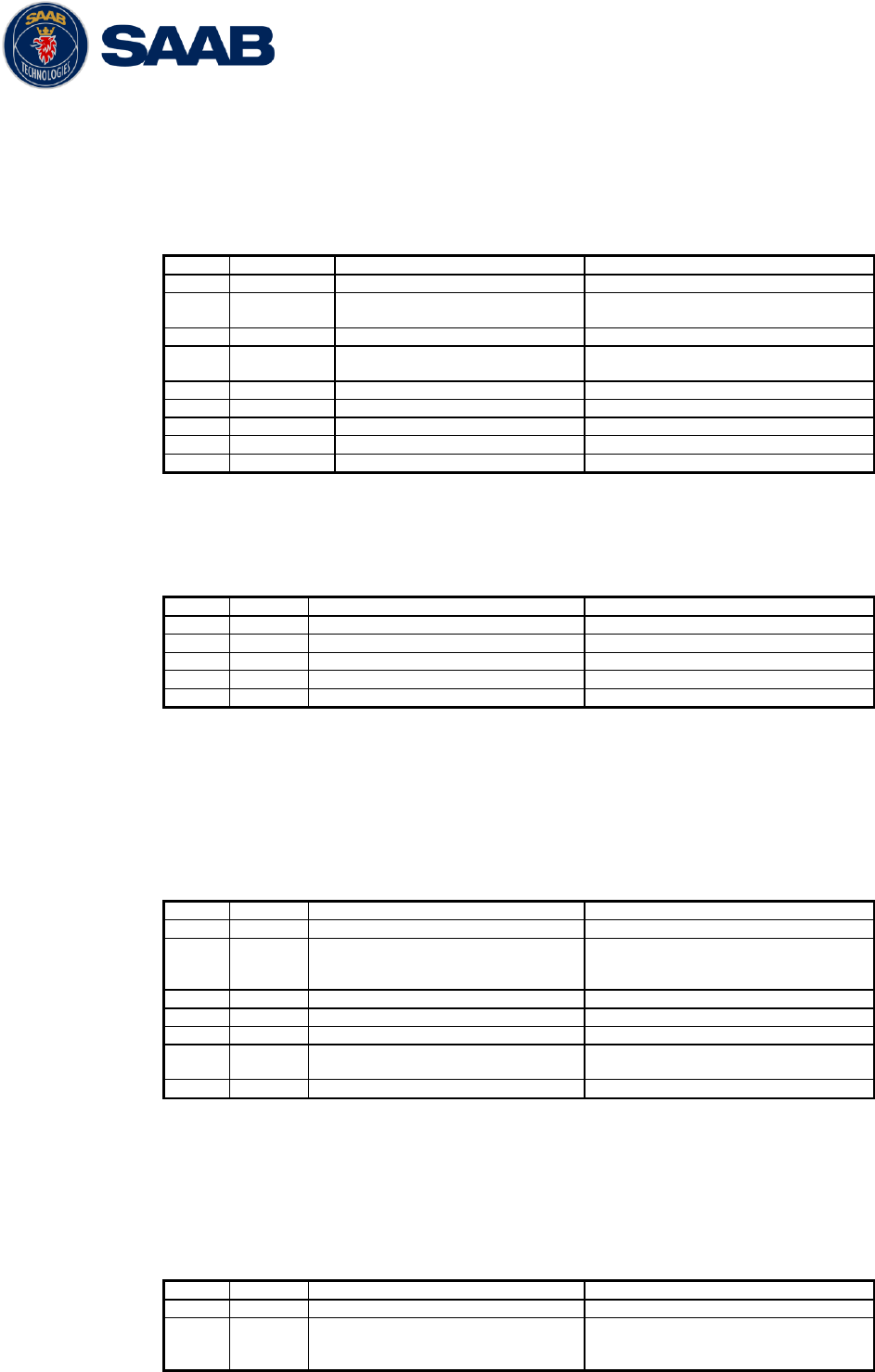
R5 SOLID AIS System
INTERPRETATION OF OUTPUT SENTENCES
7000 118-200, A4 Page 76
9.3.7 TRL – AIS transmitter non functioning log
$--TRL,x.x,x.x,x,xxxxxxxx,hhmmss.ss,xxxxxxxx,hhmmss.ss,x
Output rate: On request. Up to 10 sentences in a burst.
Field
Format
Name
Comment
1
--TRL
Sentence Id
Used
2
x.x
Total number of log
entries
Used
3
x.x
Log entry number
Used
4
x
Sequential message
identifier
Used
5
xxxxxxxx
Switch off date
Used
6
hhmmss.ss
Switch off UTC time
Used
7
xxxxxxxx
Switch on date
Used
8
hhmmss.ss
Switch on UTC time
Used
9
X
Reason code1
Used
9.3.8 TXT – Text transmission
$--TXT,xx,xx,xx,c--c
Output rate: On request, on event.
Field
Format
Name
Comment
1
--TXT
Sentence Id
Used
2
xx
Total number of sentences
Used
3
xx
Sentence number
Used
4
xx
Text identifier
Used
5
c--c
Text message
Used
9.3.9 VDM – AIS VHF data-link message
!--VDM,x,x,x,a,s—s,x
Only output on serial port when baudrate is 38400 bps or higher.
Output rate: On VHF message receive event.
Field
Format
Name
Comment
1
--VDM
Sentence Id
Used
2
X
Total number of sentences
needed to transfer the
message
Used
3
X
Sentence number
Used
4
X
Sequential message identifier
Used
5
A
AIS channel
Used
6
s—s
Encapsulated ITU-R M.1371
radio message
Used
7
X
Number of fill bits
Used
9.3.10 VDO – AIS VHF data-link own-vessel report
!--VDO,x,x,x,a,s—s,x
Only output on serial port when baudrate is 38400 bps or higher.
Output rate: On VHF transmission event. “Dummy” messages once
per second.
Field
Format
Name
Comment
1
--VDO
Sentence Id
Used
2
X
Total number of sentences
needed to transfer the
message
Used
R5 SOLID AIS System
INTERPRETATION OF OUTPUT SENTENCES
7000 118-200, A4 Page 77
3
X
Sentence number
Used
4
X
Sequential message identifier
Used
5
A
AIS channel
Used for transmission event.
Not used for “dummy” position
messages.
6
s—s
Encapsulated ITU-R M.1371
radio message
Used
7
X
Number of fill bits
Used
9.3.11 VSD – Voyage Static Data
$--VSD,x.x,x.x,x.x,c--c,hhmmss.ss,xx,xx,x.x,x.x
Output rate: On request.
Field
Format
Name
Comment
1
--VSD
Sentence Id
Used
2
x.x
Type of ship and cargo
Used
3
x.x
Maximum present draught
Used
4
x.x
Persons on-board
Used
5
c--c
Destination
Used
6
hhmmss.
ss
Est. UTC of arrival
Used
7
Xx
Est. day of arrival
Used
8
Xx
Est. month of arrival
Used
9
x.x
Navigational status
Used
10
x.x
Regional application flags
Used

R5 SOLID AIS System
GLOSSARY
7000 118-200, A4 Page 78
10 GLOSSARY
ACK
Acknowledgement
AFSK
Audio Frequency Shift Keying
AIS
Automatic Identification System
Ant
Antenna
App
Application
ARPA
Automatic Radar Plotting Aid
BRG
Bearing
BS
Base Station
Ch
Channel
COG
Course Over Ground
Comm
Communication
DGNSS
Differential Global Navigational Satellite System
Disp
Display
DTE
Data terminal equipment
DSC
Digital Selective Calling
ECDIS
Electronic Chart Display and Information System
EGNOS
European Geostationary Navigation Overlay Service
EPFS
Electronic Position Fixing System
ETA
Estimated Time of Arrival
Ext
External
GALILEO
European GNSS
GLONASS
Russian GNSS
GMSK
Gaussian Minimum Shift Keying
GNSS
Global Navigational Satellite System
GPS
Global Positioning System
HDG
Heading
HDOP
Horizontal Dilution Of Precision
Hecto
Hectometre
H/W
Hardware
IALA
International Association of Lighthouse Authorities
ID
Identifier
IEC
International Electrotechnical Commission
IMO
International Maritime Organization
Int
Internal
ITU
International Telecommunications Union
LAT
Latitude
LED
Light Emitting Diod

R5 SOLID AIS System
GLOSSARY
7000 118-200, A4 Page 79
LOC
Local
LON
Longitude
LR
Long Range
Msg
Message
MKD
Minimum Keyboard and Display
MSAS
MTSAT Satellite Augmentation System (Japan)
NMEA
National Marine Electronics Association
MMSI
Maritime Mobile Service Identity
N/A
Not available
NE
North East
No
Number
NVM
Non-Volatile Memory
PoB
Persons on board
Pos
Position
RAIM
Receiver Autonomous Integrity Monitoring
RNG
Range
RATDMA
Random Access Time Division Multiple Access
ROT
Rate Of Turn
RTA
Recommended Time of Arrival
Rx
Receive
SAR
Search And Rescue
SART
Search And Rescue Transmitter
SBAS
Satellite Based Augmentation System
SNR
Signal to Noise Ratio
SOG
Speed Over Ground
SRM
Safety Related Message
Sync
Synchronization
SW
South West
S/W
Software
TDMA
Time Division Multiple Access
Transp
Transponder
Tx
Transmit
UN
Unitied Nation
UTC
Universal Time Coordinated
VHF
Very High Frequency
VSWR
Voltage Standing Wave Ratio. (A low value indicates a problem with the
antenna or connections/cables to the antenna.)
WAAS
Wide Area Augmentation System (United States)

R5 SOLID AIS System
GLOSSARY
7000 118-200, A4 Page 80
10.1 Units
bps
Bits per second
W
Watt
m
Meter
kHz
Kilo Herz
dB-Hz
Decibel-Hertz
NM
Nautical Mile
Km
Kilometer
Sm
Statute Mile
Kn
Knots
km/h
Kilometer per Hour
mph
Miles per Hour
mm-dd hh:mm
month-day hour:minute
h:m:s
hours:minutes:seconds

R5 SOLID AIS System
APPENDIX A - LICENSE
7000 118-200, A4 Page 81
11 APPENDIX A - LICENSE
The R5 SOLID AIS Transponder System runs on a Linux operating system which is licensed
with GNU General Public License. The source code of the linux kernel can be obtained by
contacting Saab TransponderTech AB:
Saab TransponderTech AB
Låsbläcksgatan 3
589 31 Linköping
Sweden
Email: support.transpondetech@saabgroup.com
11.1 Copy of the GNU General Public License
GNU GENERAL PUBLIC LICENSE
Version 3, 29 June 2007
Copyright © 2007 Free Software Foundation, Inc. <http://fsf.org/>
Everyone is permitted to copy and distribute verbatim copies of this license document, but changing it is not allowed.
Preamble
The GNU General Public License is a free, copyleft license for software and other kinds of works.
The licenses for most software and other practical works are designed to take away your freedom to share and change the works. By contrast, the GNU General Public
License is intended to guarantee your freedom to share and change all versions of a program--to make sure it remains free software for all its users. We, the Free
Software Foundation, use the GNU General Public License for most of our software; it applies also to any other work released this way by its authors. You can apply it to
your programs, too.
When we speak of free software, we are referring to freedom, not price. Our General Public Licenses are designed to make sure that you have the freedom to distribute
copies of free software (and charge for them if you wish), that you receive source code or can get it if you want it, that you can change the software or use pieces of it in
new free programs, and that you know you can do these things.
To protect your rights, we need to prevent others from denying you these rights or asking you to surrender the rights. Therefore, you have certain responsibilities if you
distribute copies of the software, or if you modify it: responsibilities to respect the freedom of others.
For example, if you distribute copies of such a program, whether gratis or for a fee, you must pass on to the recipients the same freedoms that you received. You must
make sure that they, too, receive or can get the source code. And you must show them these terms so they know their rights.
Developers that use the GNU GPL protect your rights with two steps: (1) assert copyright on the software, and (2) offer you this License giving you legal permission to
copy, distribute and/or modify it.
For the developers' and authors' protection, the GPL clearly explains that there is no warranty for this free software. For both users' and authors' sake, the GPL requires
that modified versions be marked as changed, so that their problems will not be attributed erroneously to authors of previous versions.
Some devices are designed to deny users access to install or run modified versions of the software inside them, although the manufacturer can do so. This is
fundamentally incompatible with the aim of protecting users' freedom to change the software. The systematic pattern of such abuse occurs in the area of products for
individuals to use, which is precisely where it is most unacceptable. Therefore, we have designed this version of the GPL to prohibit the practice for those products. If such
problems arise substantially in other domains, we stand ready to extend this provision to those domains in future versions of the GPL, as needed to protect the freedom of
users.
Finally, every program is threatened constantly by software patents. States should not allow patents to restrict development and use of software on general-purpose
computers, but in those that do, we wish to avoid the special danger that patents applied to a free program could make it effectively proprietary. To prevent this, the GPL
assures that patents cannot be used to render the program non-free.
The precise terms and conditions for copying, distribution and modification follow.
TERMS AND CONDITIONS
0. Definitions.
“This License” refers to version 3 of the GNU General Public License.
“Copyright” also means copyright-like laws that apply to other kinds of works, such as semiconductor masks.
“The Program” refers to any copyrightable work licensed under this License. Each licensee is addressed as “you”. “Licensees” and “recipients” may be individuals or
organizations.
To “modify” a work means to copy from or adapt all or part of the work in a fashion requiring copyright permission, other tha n the making of an exact copy. The resulting
work is called a “modified version” of the earlier work or a work “based on” the earlier work.
A “covered work” means either the unmodified Program or a work based on the Program.
To “propagate” a work means to do anything with it that, without permission, would make you directly or secondarily liable for infringement under applicable copyright law,
except executing it on a computer or modifying a private copy. Propagation includes copying, distribution (with or without modification), making available to the public, and
in some countries other activities as well.
To “convey” a work means any kind of propagation that enables other parties to make or receive copies. Mere interaction with a user through a computer network, with no
transfer of a copy, is not conveying.
An interactive user interface displays “Appropriate Legal Notices” to the extent that it includes a convenient and prominently visible feature that (1) displays an appropriate
copyright notice, and (2) tells the user that there is no warranty for the work (except to the extent that warranties are provided), that licensees may convey the work under
this License, and how to view a copy of this License. If the interface presents a list of user commands or options, such as a menu, a prominent item in the list meets this
criterion.

R5 SOLID AIS System
APPENDIX A - LICENSE
7000 118-200, A4 Page 82
1. Source Code.
The “source code” for a work means the preferred form of the work for making modifications to it. “Object code” means any non-source form of a work.
A “Standard Interface” means an interface that either is an official standard defined by a recognized standards body, or, in the case of interfaces specified for a particular
programming language, one that is widely used among developers working in that language.
The “System Libraries” of an executable work include anything, other than the work as a whole, that (a) is included in the normal form of packaging a Major Component,
but which is not part of that Major Component, and (b) serves only to enable use of the work with that Major Component, or to implement a Standard Interface for which an
implementation is available to the public in source code form. A “Major Component”, in this context, means a major essential component (kernel, window system, and s o
on) of the specific operating system (if any) on which the executable work runs, or a compiler used to produce the work, or an object code interpreter used to run it.
The “Corresponding Source” for a work in object code form means all the source code needed to generate, install, and (for an executable work) run the object code and to
modify the work, including scripts to control those activities. However, it does not include the work's System Libraries, or general-purpose tools or generally available free
programs which are used unmodified in performing those activities but which are not part of the work. For example, Corresponding Source includes interface definition files
associated with source files for the work, and the source code for shared libraries and dynamically linked subprograms that the work is specifically designed to require,
such as by intimate data communication or control flow between those subprograms and other parts of the work.
The Corresponding Source need not include anything that users can regenerate automatically from other parts of the Corresponding Source.
The Corresponding Source for a work in source code form is that same work.
2. Basic Permissions.
All rights granted under this License are granted for the term of copyright on the Program, and are irrevocable provided the stated conditions are met. This License
explicitly affirms your unlimited permission to run the unmodified Program. The output from running a covered work is covered by this License only if the output, given its
content, constitutes a covered work. This License acknowledges your rights of fair use or other equivalent, as provided by copyright law.
You may make, run and propagate covered works that you do not convey, without conditions so long as your license otherwise remains in force. You may convey covered
works to others for the sole purpose of having them make modifications exclusively for you, or provide you with facilities for running those works, provided that you comply
with the terms of this License in conveying all material for which you do not control copyright. Those thus making or running the covered works for you must do so
exclusively on your behalf, under your direction and control, on terms that prohibit them from making any copies of your copyrighted material outside their relationship with
you.
Conveying under any other circumstances is permitted solely under the conditions stated below. Sublicensing is not allowed; section 10 makes it unnecessary.
3. Protecting Users' Legal Rights From Anti-Circumvention Law.
No covered work shall be deemed part of an effective technological measure under any applicable law fulfilling obligations under article 11 of the WIPO copyright treaty
adopted on 20 December 1996, or similar laws prohibiting or restricting circumvention of such measures.
When you convey a covered work, you waive any legal power to forbid circumvention of technological measures to the extent such circumvention is effected by exercising
rights under this License with respect to the covered work, and you disclaim any intention to limit operation or modification of the work as a means of enforcing, against the
work's users, your or third parties' legal rights to forbid circumvention of technological measures.
4. Conveying Verbatim Copies.
You may convey verbatim copies of the Program's source code as you receive it, in any medium, provided that you conspicuously and appropriately publish on each copy
an appropriate copyright notice; keep intact all notices stating that this License and any non-permissive terms added in accord with section 7 apply to the code; keep intact
all notices of the absence of any warranty; and give all recipients a copy of this License along with the Program.
You may charge any price or no price for each copy that you convey, and you may offer support or warranty protection for a fee.
5. Conveying Modified Source Versions.
You may convey a work based on the Program, or the modifications to produce it from the Program, in the form of source code under the terms of section 4, provided that
you also meet all of these conditions:
a) The work must carry prominent notices stating that you modified it, and giving a relevant date.
b) The work must carry prominent notices stating that it is released under this License and any conditions added under section 7. This requirement modifies the
requirement in section 4 to “keep intact all notices”.
c) You must license the entire work, as a whole, under this License to anyone who comes into possession of a copy. This License will therefore apply, along with any
applicable section 7 additional terms, to the whole of the work, and all its parts, regardless of how they are packaged. This License gives no permission to license the work
in any other way, but it does not invalidate such permission if you have separately received it.
d) If the work has interactive user interfaces, each must display Appropriate Legal Notices; however, if the Program has interactive interfaces that do not display
Appropriate Legal Notices, your work need not make them do so.
A compilation of a covered work with other separate and independent works, which are not by their nature extensions of the covered work, and which are not combined
with it such as to form a larger program, in or on a volume of a storage or distribution medium, is called an “aggregate” if the compilation and its resulting copyright are not
used to limit the access or legal rights of the compilation's users beyond what the individual works permit. Inclusion of a covered work in an aggregate does not cause this
License to apply to the other parts of the aggregate.
6. Conveying Non-Source Forms.
You may convey a covered work in object code form under the terms of sections 4 and 5, provided that you also convey the machine-readable Corresponding Source
under the terms of this License, in one of these ways:
a) Convey the object code in, or embodied in, a physical product (including a physical distribution medium), accompanied by the Corresponding Source fixed on a
durable physical medium customarily used for software interchange.
b) Convey the object code in, or embodied in, a physical product (including a physical distribution medium), accompanied by a written offer, valid for at least three years
and valid for as long as you offer spare parts or customer support for that product model, to give anyone who possesses the object code either (1) a copy of the
Corresponding Source for all the software in the product that is covered by this License, on a durable physical medium customarily used for software interchange, for a
price no more than your reasonable cost of physically performing this conveying of source, or (2) access to copy the Corresponding Source from a network server at no
charge.
c) Convey individual copies of the object code with a copy of the written offer to provide the Corresponding Source. This alternative is allowed only occasionally and
noncommercially, and only if you received the object code with such an offer, in accord with subsection 6b.
d) Convey the object code by offering access from a designated place (gratis or for a charge), and offer equivalent access to the Corresponding Source in the same way
through the same place at no further charge. You need not require recipients to copy the Corresponding Source along with the object code. If the place to copy the object
code is a network server, the Corresponding Source may be on a different server (operated by you or a third party) that supports equivalent copying facilities, provided you
maintain clear directions next to the object code saying where to find the Corresponding Source. Regardless of what server hosts the Corresponding Source, you remain
obligated to ensure that it is available for as long as needed to satisfy these requirements.
e) Convey the object code using peer-to-peer transmission, provided you inform other peers where the object code and Corresponding Source of the work are being
offered to the general public at no charge under subsection 6d.

R5 SOLID AIS System
APPENDIX A - LICENSE
7000 118-200, A4 Page 83
A separable portion of the object code, whose source code is excluded from the Corresponding Source as a System Library, need not be included in conveying the object
code work.
A “User Product” is either (1) a “consumer product”, which means any tangible personal property which is normally used for personal, family, or household purposes, or (2)
anything designed or sold for incorporation into a dwelling. In determining whether a product is a consumer product, doubtful cases shall be resolved in favor of coverage.
For a particular product received by a particular user, “normally used” refers to a typical or common use of that class of pr oduct, regardless of the status of the particular
user or of the way in which the particular user actually uses, or expects or is expected to use, the product. A product is a consumer product regardless of whether the
product has substantial commercial, industrial or non-consumer uses, unless such uses represent the only significant mode of use of the product.
“Installation Information” for a User Product means any methods, procedures, authorization keys, or other information required to install and execute modified versions of a
covered work in that User Product from a modified version of its Corresponding Source. The information must suffice to ensure that the continued functioning of the
modified object code is in no case prevented or interfered with solely because modification has been made.
If you convey an object code work under this section in, or with, or specifically for use in, a User Product, and the conveying occurs as part of a transaction in which the
right of possession and use of the User Product is transferred to the recipient in perpetuity or for a fixed term (regardless of how the transaction is characterized), the
Corresponding Source conveyed under this section must be accompanied by the Installation Information. But this requirement does not apply if neither you nor any third
party retains the ability to install modified object code on the User Product (for example, the work has been installed in ROM).
The requirement to provide Installation Information does not include a requirement to continue to provide support service, warranty, or updates for a work that has been
modified or installed by the recipient, or for the User Product in which it has been modified or installed. Access to a network may be denied when the modification itself
materially and adversely affects the operation of the network or violates the rules and protocols for communication across the network.
Corresponding Source conveyed, and Installation Information provided, in accord with this section must be in a format that is publicly documented (and with an
implementation available to the public in source code form), and must require no special password or key for unpacking, reading or copying.
7. Additional Terms.
“Additional permissions” are terms that supplement the terms of this License by making exceptions from one or more of its conditions. Additional permissions that are
applicable to the entire Program shall be treated as though they were included in this License, to the extent that they are valid under applicable law. If additional
permissions apply only to part of the Program, that part may be used separately under those permissions, but the entire Program remains governed by this License without
regard to the additional permissions.
When you convey a copy of a covered work, you may at your option remove any additional permissions from that copy, or from any part of it. (Additional permissions may
be written to require their own removal in certain cases when you modify the work.) You may place additional permissions on material, added by you to a covered work, for
which you have or can give appropriate copyright permission.
Notwithstanding any other provision of this License, for material you add to a covered work, you may (if authorized by the copyright holders of that material) supplement
the terms of this License with terms:
a) Disclaiming warranty or limiting liability differently from the terms of sections 15 and 16 of this License; or
b) Requiring preservation of specified reasonable legal notices or author attributions in that material or in the Appropriate Legal Notices displayed by works containing it;
or
c) Prohibiting misrepresentation of the origin of that material, or requiring that modified versions of such material be marked in reasonable ways as different from the
original version; or
d) Limiting the use for publicity purposes of names of licensors or authors of the material; or
e) Declining to grant rights under trademark law for use of some trade names, trademarks, or service marks; or
f) Requiring indemnification of licensors and authors of that material by anyone who conveys the material (or modified versions of it) with contractual assumptions of
liability to the recipient, for any liability that these contractual assumptions directly impose on those licensors and authors.
All other non-permissive additional terms are considered “further restrictions” within the meaning of section 10. If the Program as you received it, or any part of it, contains
a notice stating that it is governed by this License along with a term that is a further restriction, you may remove that term. If a license document contains a further
restriction but permits relicensing or conveying under this License, you may add to a covered work material governed by the terms of that license document, provided that
the further restriction does not survive such relicensing or conveying.
If you add terms to a covered work in accord with this section, you must place, in the relevant source files, a statement of the additional terms that apply to those files, or a
notice indicating where to find the applicable terms.
Additional terms, permissive or non-permissive, may be stated in the form of a separately written license, or stated as exceptions; the above requirements apply either
way.
8. Termination.
You may not propagate or modify a covered work except as expressly provided under this License. Any attempt otherwise to propagate or modify it is void, and will
automatically terminate your rights under this License (including any patent licenses granted under the third paragraph of section 11).
However, if you cease all violation of this License, then your license from a particular copyright holder is reinstated (a) provisionally, unless and until the copyright holder
explicitly and finally terminates your license, and (b) permanently, if the copyright holder fails to notify you of the violation by some reasonable means prior to 60 days after
the cessation.
Moreover, your license from a particular copyright holder is reinstated permanently if the copyright holder notifies you of the violation by some reasonable means, this is
the first time you have received notice of violation of this License (for any work) from that copyright holder, and you cure the violation prior to 30 days after your receipt of
the notice.
Termination of your rights under this section does not terminate the licenses of parties who have received copies or rights from you under this License. If your rights have
been terminated and not permanently reinstated, you do not qualify to receive new licenses for the same material under section 10.
9. Acceptance Not Required for Having Copies.
You are not required to accept this License in order to receive or run a copy of the Program. Ancillary propagation of a covered work occurring solely as a consequence of
using peer-to-peer transmission to receive a copy likewise does not require acceptance. However, nothing other than this License grants you permission to propagate or
modify any covered work. These actions infringe copyright if you do not accept this License. Therefore, by modifying or propagating a covered work, you indicate your
acceptance of this License to do so.
10. Automatic Licensing of Downstream Recipients.
Each time you convey a covered work, the recipient automatically receives a license from the original licensors, to run, modify and propagate that work, subject to this
License. You are not responsible for enforcing compliance by third parties with this License.
An “entity transaction” is a transaction transferring control of an organization, or substantially all assets of one, or subdividing an organization, or merging organizations. If
propagation of a covered work results from an entity transaction, each party to that transaction who receives a copy of the work also receives whatever licenses to the
work the party's predecessor in interest had or could give under the previous paragraph, plus a right to possession of the Corresponding Source of the work from the
predecessor in interest, if the predecessor has it or can get it with reasonable efforts.

R5 SOLID AIS System
APPENDIX A - LICENSE
7000 118-200, A4 Page 84
You may not impose any further restrictions on the exercise of the rights granted or affirmed under this License. For example, you may not impose a license fee, royalty, or
other charge for exercise of rights granted under this License, and you may not initiate litigation (including a cross-claim or counterclaim in a lawsuit) alleging that any
patent claim is infringed by making, using, selling, offering for sale, or importing the Program or any portion of it.
11. Patents.
A “contributor” is a copyright holder who authorizes use under this License of the Program or a work on which the Program is based. The work thus licensed is called the
contributor's “contributor version”.
A contributor's “essential patent claims” are all patent claims owned or controlled by the contributor, whether already acquired or hereafter acquired, that would be infringed
by some manner, permitted by this License, of making, using, or selling its contributor version, but do not include claims that would be infringed only as a consequence of
further modification of the contributor version. For purposes of this definition, “control” includes the right to grant patent sublicenses in a manner consistent with the
requirements of this License.
Each contributor grants you a non-exclusive, worldwide, royalty-free patent license under the contributor's essential patent claims, to make, use, sell, offer for sale, import
and otherwise run, modify and propagate the contents of its contributor version.
In the following three paragraphs, a “patent license” is any express agreement or commitment, however denominated, not to enforce a patent (such as an express
permission to practice a patent or covenant not to sue for patent infringement). To “grant” such a patent license to a party means to make such an agreement or
commitment not to enforce a patent against the party.
If you convey a covered work, knowingly relying on a patent license, and the Corresponding Source of the work is not available for anyone to copy, free of charge and
under the terms of this License, through a publicly available network server or other readily accessible means, then you must either (1) cause the Corresponding Source to
be so available, or (2) arrange to deprive yourself of the benefit of the patent license for this particular work, or (3) arrange, in a manner consistent with the requirements of
this License, to extend the patent license to downstream recipients. “Knowingly relying” means you have actual knowledge that, but for the patent license, your conveying
the covered work in a country, or your recipient's use of the covered work in a country, would infringe one or more identifiable patents in that country that you have reason
to believe are valid.
If, pursuant to or in connection with a single transaction or arrangement, you convey, or propagate by procuring conveyance of, a covered work, and grant a patent license
to some of the parties receiving the covered work authorizing them to use, propagate, modify or convey a specific copy of the covered work, then the patent license you
grant is automatically extended to all recipients of the covered work and works based on it.
A patent license is “discriminatory” if it does not include within the scope of its coverage, prohibits the exercise of, or is conditioned on the non-exercise of one or more of
the rights that are specifically granted under this License. You may not convey a covered work if you are a party to an arrangement with a third party that is in the business
of distributing software, under which you make payment to the third party based on the extent of your activity of conveying the work, and under which the third party grants,
to any of the parties who would receive the covered work from you, a discriminatory patent license (a) in connection with copies of the covered work conveyed by you (or
copies made from those copies), or (b) primarily for and in connection with specific products or compilations that contain the covered work, unless you entered into that
arrangement, or that patent license was granted, prior to 28 March 2007.
Nothing in this License shall be construed as excluding or limiting any implied license or other defenses to infringement that may otherwise be available to you under
applicable patent law.
12. No Surrender of Others' Freedom.
If conditions are imposed on you (whether by court order, agreement or otherwise) that contradict the conditions of this License, they do not excuse you from the
conditions of this License. If you cannot convey a covered work so as to satisfy simultaneously your obligations under this License and any other pertinent obligations, then
as a consequence you may not convey it at all. For example, if you agree to terms that obligate you to collect a royalty for further conveying from those to whom you
convey the Program, the only way you could satisfy both those terms and this License would be to refrain entirely from conveying the Program.
13. Use with the GNU Affero General Public License.
Notwithstanding any other provision of this License, you have permission to link or combine any covered work with a work licensed under version 3 of the GNU Affero
General Public License into a single combined work, and to convey the resulting work. The terms of this License will continue to apply to the part which is the covered
work, but the special requirements of the GNU Affero General Public License, section 13, concerning interaction through a network will apply to the combination as such.
14. Revised Versions of this License.
The Free Software Foundation may publish revised and/or new versions of the GNU General Public License from time to time. Such new versions will be similar in spirit to
the present version, but may differ in detail to address new problems or concerns.
Each version is given a distinguishing version number. If the Program specifies that a certain numbered version of the GNU General Public License “or any later version”
applies to it, you have the option of following the terms and conditions either of that numbered version or of any later version published by the Free Software Foundation. If
the Program does not specify a version number of the GNU General Public License, you may choose any version ever published by the Free Software Foundation.
If the Program specifies that a proxy can decide which future versions of the GNU General Public License can be used, that proxy's public statement of acceptance of a
version permanently authorizes you to choose that version for the Program.
Later license versions may give you additional or different permissions. However, no additional obligations are imposed on any author or copyright holder as a result of
your choosing to follow a later version.
15. Disclaimer of Warranty.
THERE IS NO WARRANTY FOR THE PROGRAM, TO THE EXTENT PERMITTED BY APPLICABLE LAW. EXCEPT WHEN OTHERWISE STATED IN WRITING THE
COPYRIGHT HOLDERS AND/OR OTHER PARTIES PROVIDE THE PROGRAM “AS IS” WITHOUT WARRANTY OF ANY KIND, EITHER EXPRESSED OR IMPLIED,
INCLUDING, BUT NOT LIMITED TO, THE IMPLIED WARRANTIES OF MERCHANTABILITY AND FITNESS FOR A PARTICULAR PURPOSE. THE ENTIRE RISK AS
TO THE QUALITY AND PERFORMANCE OF THE PROGRAM IS WITH YOU. SHOULD THE PROGRAM PROVE DEFECTIVE, YOU ASSUME THE COST OF ALL
NECESSARY SERVICING, REPAIR OR CORRECTION.
16. Limitation of Liability.
IN NO EVENT UNLESS REQUIRED BY APPLICABLE LAW OR AGREED TO IN WRITING WILL ANY COPYRIGHT HOLDER, OR ANY OTHER PARTY WHO
MODIFIES AND/OR CONVEYS THE PROGRAM AS PERMITTED ABOVE, BE LIABLE TO YOU FOR DAMAGES, INCLUDING ANY GENERAL, SPECIAL, INCIDENTAL
OR CONSEQUENTIAL DAMAGES ARISING OUT OF THE USE OR INABILITY TO USE THE PROGRAM (INCLUDING BUT NOT LIMITED TO LOSS OF DATA OR
DATA BEING RENDERED INACCURATE OR LOSSES SUSTAINED BY YOU OR THIRD PARTIES OR A FAILURE OF THE PROGRAM TO OPERATE WITH ANY
OTHER PROGRAMS), EVEN IF SUCH HOLDER OR OTHER PARTY HAS BEEN ADVISED OF THE POSSIBILITY OF SUCH DAMAGES.
17. Interpretation of Sections 15 and 16.
If the disclaimer of warranty and limitation of liability provided above cannot be given local legal effect according to their terms, reviewing courts shall apply local law that
most closely approximates an absolute waiver of all civil liability in connection with the Program, unless a warranty or assumption of liability accompanies a copy of the
Program in return for a fee.
END OF TERMS AND CONDITIONS
How to Apply These Terms to Your New Programs
If you develop a new program, and you want it to be of the greatest possible use to the public, the best way to achieve this is to make it free software which everyone can
redistribute and change under these terms.
To do so, attach the following notices to the program. It is safest to attach them to the start of each source file to most effectively state the exclusion of warranty; and each
file should have at least the “copyright” line and a pointer to where the full notice is found.

R5 SOLID AIS System
APPENDIX A - LICENSE
7000 118-200, A4 Page 85
<one line to give the program's name and a brief idea of what it does.>
Copyright (C) <year> <name of author>
This program is free software: you can redistribute it and/or modify
it under the terms of the GNU General Public License as published by
the Free Software Foundation, either version 3 of the License, or
(at your option) any later version.
This program is distributed in the hope that it will be useful,
but WITHOUT ANY WARRANTY; without even the implied warranty of
MERCHANTABILITY or FITNESS FOR A PARTICULAR PURPOSE. See the
GNU General Public License for more details.
You should have received a copy of the GNU General Public License
along with this program. If not, see <http://www.gnu.org/licenses/>.
Also add information on how to contact you by electronic and paper mail.
If the program does terminal interaction, make it output a short notice like this when it starts in an interactive mode:
<program> Copyright (C) <year> <name of author>
This program comes with ABSOLUTELY NO WARRANTY; for details type `show w'.
This is free software, and you are welcome to redistribute it
under certain conditions; type `show c' for details.
The hypothetical commands `show w' and `show c' should show the appropriate parts of the General Public License. Of course, your program's commands might be
different; for a GUI interface, you would use an “about box”.
You should also get your employer (if you work as a programmer) or school, if any, to sign a “copyright disclaimer” for the p rogram, if necessary. For more information on
this, and how to apply and follow the GNU GPL, see <http://www.gnu.org/licenses/>.
The GNU General Public License does not permit incorporating your program into proprietary programs. If your program is a subroutine library, you may consider it more
useful to permit linking proprietary applications with the library. If this is what you want to do, use the GNU Lesser General Public License instead of this License. But first,
please read <http://www.gnu.org/philosophy/why-not-lgpl.html>.