Saab TransponderTech R5-AIS R5 SUPREME AIS User Manual Manual
Saab TransponderTech AB R5 SUPREME AIS Manual
Contents
- 1. manual
- 2. Manual
Manual
OPERATION & INSTALLATION MANUAL
Saab TransponderTech
R5
SUPREME AIS
Transponder System
This page is intentionally empty

R5 SUPREME AIS System
THE AUTOMATIC IDENTIFICATION SYSTEM
7000 118-300, B1 Page 3
i Copyright
The entire contents of this manual and its appendices, including any
future updates and modifications, shall remain the property of Saab
TransponderTech AB at all times. The contents must not, whether in
its original form or modified, be wholly or partly copied or reproduced,
nor used for any other purpose than the subject of this manual.
Saab TransponderTech AB, SWEDEN
ii Disclaimer
While reasonable care has been exercised in the preparation of this
manual, Saab TransponderTech AB shall incur no liability whatsoever
based on the contents or lack of contents in the manual.
iii Software
This manual reflects the capabilities of the R5 SUPREME AIS
Transponder with Software version 1.0.12 and R5 SUPREME Control
& Display Unit (CDU) with software version 1.0.12.
If the system since delivery has been updated from this version, such
change should be reflected on a label on the unit. Current software
versions in the system can always be verified in the S/W info dialog as
described in section 5.21.
iv Manual Part Number and Revision
Part number 7000 118-300, revision B1.
v Safety Instructions
Note the following compass safe distances:
Equipment
Standard magnetic
compass
Steering magnetic
compass
R5 SUPREME
Transponder
0,65 m
0,40 m
R5 SUPREME CDU
0,75 m
0,50 m
vi Disposal Instructions
Broken or unwanted electrical or electronic equipment parts shall be
classified and handled as ‘Electronic Waste’. Improper disposal may
be harmful to the environment and human health. Please refer to your
local waste authority for information on return and collection systems
in your area.

R5 SUPREME AIS System
THE AUTOMATIC IDENTIFICATION SYSTEM
7000 118-300, B1 Page 4
vii Contact Information
For installation, service, ordering info and technical support please
contact your local Saab TransponderTech representative. A list of
dealers and service stations can be found on the corresponding
product page at www.saabgroup.com/transpondertech.

R5 SUPREME AIS System
THE AUTOMATIC IDENTIFICATION SYSTEM
7000 118-300, B1 Page 5
TABLE OF CONTENTS
1 The Automatic Identification System ........................................... 8
2 System Overview ........................................................................... 9
2.1 Product Description ............................................................................................... 9
3 Installation .................................................................................... 10
3.1 Unpacking the Equipment .................................................................................... 10
3.2 Equipment Installation Environment ................................................................... 11
3.3 Installation Cables ................................................................................................ 11
3.4 System interconnection overview ....................................................................... 13
3.5 Installation Procedure .......................................................................................... 14
3.6 Installing the R5 SUPREME CDU ......................................................................... 14
3.8 Installing the R5 SUPREME Transponder ........................................................... 17
3.9 Install the R5 AIS Junction Box ........................................................................... 18
3.10 Mount the VHF Antenna ....................................................................................... 20
3.11 Mount the GPS Antenna ....................................................................................... 22
3.12 Electrical Installation details ................................................................................ 24
4 Configuration ............................................................................... 30
4.1 Configuration Wizard............................................................................................ 30
4.2 System Functional Check .................................................................................... 33
4.3 Configuration Parameters .................................................................................... 33
5 Operation ...................................................................................... 45
5.1 General usage ....................................................................................................... 45
5.2 LED’s on R5 SUPREME Transponder ................................................................. 45
5.3 LED’s and Controls on R5 SUPREME CDU ......................................................... 46
5.4 Menu Structure – Tree view ................................................................................. 49
5.5 Alarm and Alert Pop-ups ...................................................................................... 50
5.6 Status Bar.............................................................................................................. 50
5.7 Status Icons .......................................................................................................... 51
5.8 View Remote Ship Information ............................................................................ 52
5.9 View Plot of Targets ............................................................................................. 53
5.10 View Transmitted Own Ship Information ............................................................ 53
5.11 Enter and Read Voyage Related Information ...................................................... 54
5.12 Handling Safety Related Messages (SRM) and Text Messages......................... 54
5.13 Send Persons On Board ....................................................................................... 56
5.14 Long Range Interrogations .................................................................................. 57

R5 SUPREME AIS System
THE AUTOMATIC IDENTIFICATION SYSTEM
7000 118-300, B1 Page 6
5.15 Regional Areas...................................................................................................... 58
5.16 Alarms ................................................................................................................... 58
5.17 Status List ............................................................................................................. 59
5.18 Non Functional Time ............................................................................................ 59
5.19 AIS Internal GPS Status ....................................................................................... 60
5.20 View Raw Data ...................................................................................................... 60
5.21 SW/HW Info ........................................................................................................... 61
5.22 VHF Status ............................................................................................................ 61
5.23 Communication Test ............................................................................................ 62
5.24 Update Software ................................................................................................... 63
5.25 Factory reset ......................................................................................................... 63
6 Software Upgrade ........................................................................ 64
6.1 Upgrade Software in R5 SUPREME Transponder via Junction Box. ................ 64
6.2 Upgrade Software in R5 SUPREME Transponder via CDU ................................ 64
6.3 License Upgrade ................................................................................................... 66
6.4 Upgrade Software in R5 SUPREME CDU ............................................................ 67
7 Technincal Specifications ........................................................... 68
7.1 R5 SUPREME Transponder .................................................................................. 68
7.2 R5 SUPREME CDU ................................................................................................ 69
7.1 R5 AIS Junction Box ............................................................................................ 70
8 Troubleshooting ........................................................................... 71
8.1 Troubleshooting Prerequisites ............................................................................ 71
8.2 Troubleshooting with the Front Panel LED’s of the Transponder ..................... 71
8.3 Troubleshooting with Alarm Messages............................................................... 72
8.4 Troubleshooting via the CDU ............................................................................... 74
8.5 Reporting Intervals for Class A Transponders ................................................... 76
8.6 F.A.Q ...................................................................................................................... 77
8.7 Contacting Support .............................................................................................. 78
8.8 Indication Messages ............................................................................................. 78
8.9 Long Range Definitions ........................................................................................ 79
9 Interpretation of Input Sentences ............................................... 80
9.1 GPS and Sensor Input Sentences ....................................................................... 80
9.2 General Input Sentences ...................................................................................... 84
9.3 AIS Specific Input Sentences ............................................................................... 84
9.4 Long Range Input Sentences ............................................................................... 86
9.5 Proprietary Input Sentences ................................................................................ 87

R5 SUPREME AIS System
THE AUTOMATIC IDENTIFICATION SYSTEM
7000 118-300, B1 Page 7
10 Interpretation of Output Sentences ............................................ 88
10.1 Proprietary Output Sentences (PSTT) ................................................................. 88
10.2 Long Range Output Sentences ............................................................................ 89
10.3 AIS Output Sentences .......................................................................................... 91
11 Alternate System Setups ............................................................. 95
11.1 Dual CDU ............................................................................................................... 95
11.2 Combined AIS and Navigation system setup ..................................................... 96
12 Electrical Interfaces ..................................................................... 97
12.1 Transponder interface details .............................................................................. 97
12.2 R5 AIS Junction box Interfaces ........................................................................... 99
12.3 CDU Interfaces: ................................................................................................... 103
13 Mechanical Drawings ................................................................. 105
13.1 Transponder Physical Size and Mechanical Drawing ...................................... 105
13.2 CDU Physical Size and Mechanical Drawing .................................................... 106
13.3 CDU Gimbal Mount Physical Size and Mechanical Drawing ............................ 107
13.4 CDU Cutout Measurements for Panel Mount .................................................... 108
13.5 CDU Mounting Frame cutout and dimensions .................................................. 109
13.6 R5 AIS Junction Box Physical Size and Mechanical Drawing ......................... 110
13.7 GPS Antenna – Physical Size and Mechanical Drawing .................................. 111
14 Glossary ..................................................................................... 112
14.1 Units .................................................................................................................... 114
15 Appendix A – License ................................................................ 115
15.1 Copy of the GNU General Public License ......................................................... 115

R5 SUPREME AIS System
THE AUTOMATIC IDENTIFICATION SYSTEM
7000 118-300, B1 Page 8
1 THE AUTOMATIC IDENTIFICATION SYSTEM
The Automatic Identification System (AIS) is a safety information system that was proposed as a
worldwide standard in 1997 and adopted by IMO in 1998. The AIS system is standardized by ITU,
IEC, IALA and IMO and is subject to approval by a certification body. The first type approved AIS
transponder in the world was Saab TransponderTech’s R3 Class A Transponder in 2002.
AIS allows transceivers to automatically share static and dynamic data such as ship name, call sign,
dimensions, position and sensor information on two dedicated data links in the upper marine VHF
band. There are a number of different AIS devices that can send and receive information on the AIS
data link:
Class A Transponder – This type of transponder is used on open sea waters and is
mandatory for ships of 300 gross tonnage or more on international voyages, all cargo ships
of 500 gross tonnage or more and on passenger ships.
Class B Transponder – Used on smaller vessels and pleasure crafts. It transmits with a
lower power than the class A transponder and has lower priority on the data link.
Base Station – Fixed shore station that is typically connected to an AIS network to collect
information from all vessels at a certain port or shore line.
Repeater Stations – Used to extend coverage range by repeating incoming messages. Can
be implemented as a function in an AIS Base station or an AtoN station.
SAR (Search and Rescue) Transponder – Used on airplanes and helicopters in search and
rescue missions.
AtoN (Aids to Navigation) – A transceiver that is fitted on buoys and lighthouses in order to
send information about their positions.
Inland AIS – A European standardized extension to Class A systems for use on inland water
ways. An inland transponder has additional messages to communicate with bridges, ports
and locks and can also send some additional information that are useful on water ways such
as blue sign indication, specific hazardous cargo etc.
SART (Search and Rescue Transmitters) – Distress beacons for life rafts. An active SART
unit will always be sorted on top of the target list in the R5 SUPREME CDU to accentuate its
presence.

R5 SUPREME AIS System
SYSTEM OVERVIEW
7000 118-300, B1 Page 9
2 SYSTEM OVERVIEW
2.1 Product Description
The basic R5 SUPREME AIS Transponder System consists of three parts
The R5 SUPREME Transponder
The R5 SUPREME Control and Display Unit (CDU)
The R5 AIS Junction Box
The R5 SUPREME Transponder is a Class A unit consists of a transceiver radio unit, a 50
channel GPS receiver, and a controller unit. The radio has three receivers, two tuneable TDMA
receivers and one DSC receiver. The transmitter alternates its transmissions between the two
operating TDMA channels. The controller unit creates and schedules data packets (containing
dynamic, static and voyage related data) for transmission based on the IMO performance
standard for AIS.
The R5 SUPREME CDU is the AIS configuration and display unit. The colour LCD together with
the resistive touch interface provides a graphical user-friendly interface to the system. The
resistive touch panel allows functionality under all weather conditions. Under rough sea, the
rubber keypads can be used instead of the touch interface. With the R5 SUPREME CDU it is
possible to plot the location of other ships, aids to navigation and search and rescue vessels. The
R5 SUPREME CDU can also be used to send and receive messages, perform configuration as
well as supervise the R5 SUPREME transponder systems status. The front hatch of the CDU is
covering an integrated AIS Pilot Plug connector, as well as USB port and MMC/SD card slot.
Note: The hatch has a screw lock mechanism. It is optional to use this lock. Recommended
screwdriver for CDU hatch lock is flat tip 5.5-6.5mm.
The R5 AIS Junction Box allows for easy connection of external equipment to the transponder
unit. The R5 SUPREME transponder shall be connected to the ship’s sensors as required by the
installation guidelines published by IALA. The R5 SUPREME can interface external navigation
and presentation systems that support required IEC 61162-1 sentences. Refer to chapter 9
“Interpretation of Input Sentences” for more information. The R5 SUPREME is prepared for
connection to Long Range systems like Inmarsat C.
R5 SUPREME AIS System
INSTALLATION
7000 118-300, B1 Page 10
3 INSTALLATION
3.1 Unpacking the Equipment
The R5 SUPREME AIS Transponder System consists of the following parts:
Name
Part number
Qty.
R5 SUPREME Transponder
7000 118-100 incl. AIS SW 1.0.X
7000 118-501
1
R5 SUPREME CDU
7000 118-100 incl. SW 1.0.X
7000 118-530
1
R5 Power Cable 2m
7000 118-077
2
R5 Signal Cable DSUB-DSUB 2m
7000 118-286
2
R5 SUPREME Documentation CD
Including
R5 SUPREME AIS System Manual
7000 118-361
7000 118-300
1
Printed document set
Including:
AIS Installation Short Instruction
AIS Operators Short Instruction
AIS Certificate set
7000 118-370
7000 118-363
7000 118-364
7000 118-365
1
R5 SUPREME Ethernet Cable 5m.
7000 000-525
1
R5 AIS Junction box
7000 118-120
1
Table 1 – R5 SUPREME Basic Equipment
Name
Part number
GPS antenna options
MA-700
AT575-68
Combined VHF/GPS Antenna AC Marine
7000 000-485
7000 000-135
7000 000-435
Stainless Steel Antenna Mount 1" x 14
7000 000-472
AIS Alarm Relay Unit incl. socket
7000 100-132
R5 SUPREME AIS System
INSTALLATION
7000 118-300, B1 Page 11
VHF Antenna BA1012
7000 000-077
R5 SUPREME CDU Flush mount frame for
R4 MKD upgrades
7000 118-367
Table 2 – Accessories (Optional)
3.2 Equipment Installation Environment
The table below lists the IEC 60945 equipment classification for the system.
Name
Part number
IEC 60945
installation category
R5 SUPREME Transponder
7000 118-540
Protected
R5 SUPREME CDU
7000 118-530
Protected
R5 AIS Junction box
7000 118-120
Protected
MA-700
AT575-68
VHF/GPS Antenna
7000 000-485
7000 000-135
7000 000-435
Exposed
Exposed
Exposed
Table 3 - IEC 60945 equipment classification
3.3 Installation Cables
The following cables are needed to install the R5 SUPREME AIS System.
1. 2 x R5 Signal Cable DSUB-DSUB
Marking: 7000 118-286
Type: Shielded Twisted Pair x 0.33 mm2
Length: 2 m
Diameter: 11 mm
Connector: 2 x 26-pole H.D.D-SUB (female to male)
Flame retardant: IEC60332-1
Interconnection: Straight connection on all pins.
Note: Two signal cables are used from transponder to junction box, but one is installed
reverse direction
R5 SUPREME AIS System
INSTALLATION
7000 118-300, B1 Page 12
(Cable 1: Male
Female. Cable 2: Female
Male)
1. 2 x R5 Power Cable
Type: Unshielded 4 wire cable x 1.3 mm2
Length: 2 m
Diameter: 6 mm
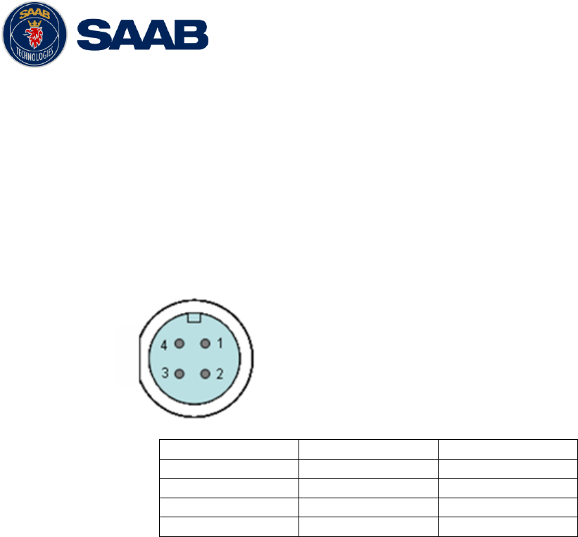
Connector: ConXall Mini-Con-X 6382-4SG-311 (female)
Marking: 7000 118-077
Interconnection specification:
Function
Pin
Cable Color
PWR +
1
Red
PWR, GND
2
Black
Ext Switch R
3
Brown
Ext Switch F
4
Orange
2. R5 SUPREME VHF Antenna Cable
Type and length: See section 3.10.2 VHF Cabling
Connector: BNC (Male)
3. R5 SUPREME GPS Antenna Cable
Type and Length: See section 3.11.2 GPS Cabling
Connector: TNC (Male)
4. R5 SUPREME Ethernet Cable
Type: Cat-7, LSZH-FR, IEC 60332-1
Length: 5 m
Diameter: 6,5 mm
Connector: RJ-45
Part number: 7000 000-525
3.3.1 Minimum cable bending radius
When installing the cables the recommended minimum bending radiuses are as follows:
Signal and power cables: 10 times cable diameter
Coaxial cables: 5 times cable diameter
R5 SUPREME AIS System
INSTALLATION
7000 118-300, B1 Page 13
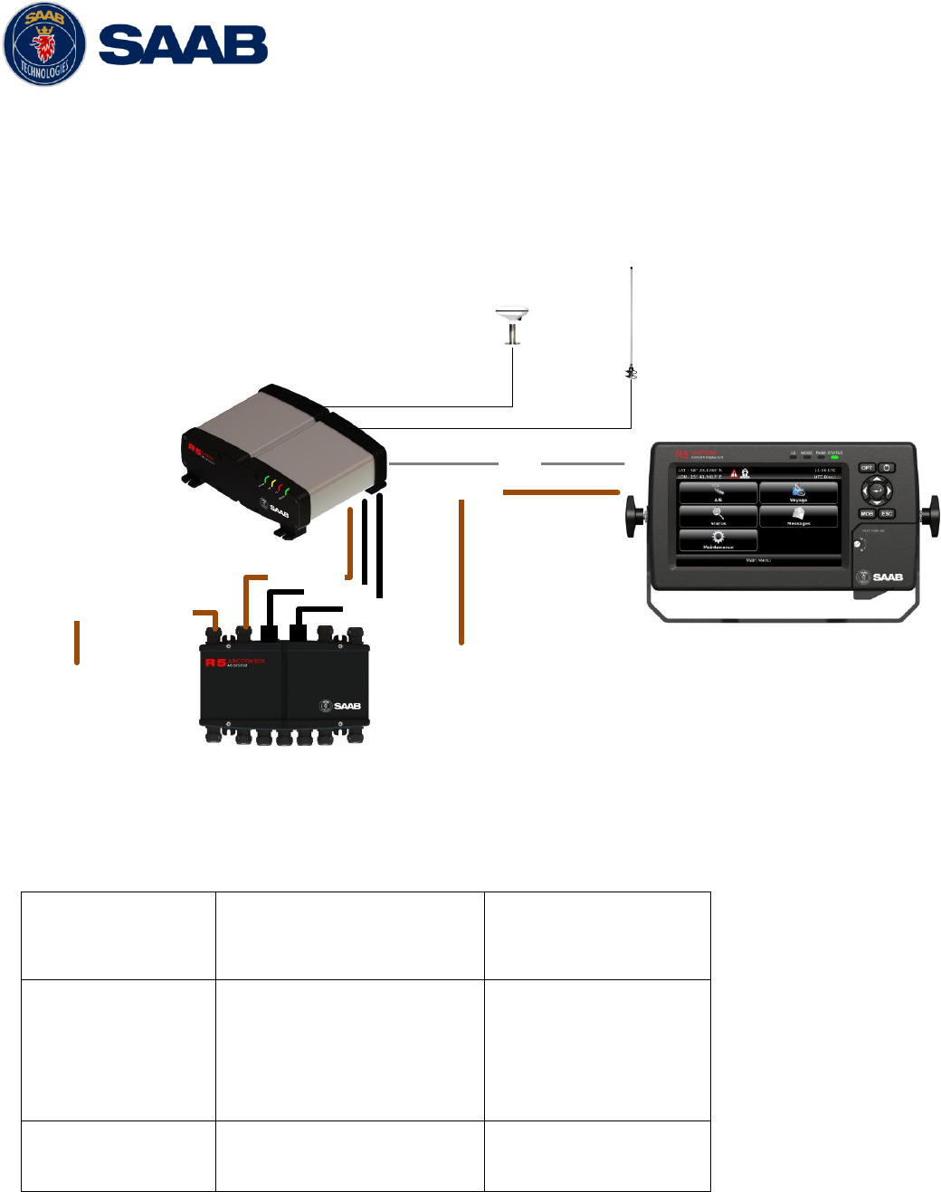
3.4 System interconnection overview
3.4.1 Standard system
Below is a general system setup with everything connected except external sensors and
systems, which is connected to the R5 AIS Junction box. For alternate system setups, please see
Section 11 “Alternate System Setups”
R5 AIS Junction Box
Ethernet
External power 12-24 VDC
R5 Transponder
R5 Signal Cable
R5 Signal Cable
R5 Power Cable
R5 CDU in AIS Mode
R5 Power Cable
May be
connected to
Junction box
AUX PWR
Terminal
VHF
GPS
Figure 1- System overview
R5 Supreme AIS Transponder
7000 118-540
R5 AIS Junction box
7000 118-120
R5 AIS Junction box
7000 118-120
2 x R5 Signal cable DSUB-DSUB
7000 118-286
R5 Power Cable
7000 118-077
-
R5 CDU
7000 118-530
R5 SUPREME Ethernet Cable,
7000 000-525
R5 Power Cable
7000 118-077
Table 4 – AIS System interconnect

R5 SUPREME AIS System
INSTALLATION
7000 118-300, B1 Page 14
3.5 Installation Procedure
When installing the R5 SUPREME AIS System it is recommended to follow the steps described in
this installation manual. Details of the installation procedure can be found in the coming sections
of the manual.
Recommended installation steps:
1. Mount the R5 SUPREME CDU at conning station
2. Mount the R5 SUPREME transponder
3. Mount the alarm relay unit (if applicable)
4. Connect all external systems and sensors to the R5 AIS Junction Box
5. Mount the R5 AIS Junction box
6. Connect the R5 SUPREME transponder and R5 SUPREME CDU directly or to Ethernet
network
7. Mount the VHF antenna
8. Mount the GPS antenna
9. Power up the system
10. Configure IP and LWE-ID settings
11. Set additional configuration parameters
12. Perform system functional check
3.6 Installing the R5 SUPREME CDU
3.6.1 CDU Location
The R5 SUPREME CDU should be mounted close to the position from which the ship is
normally operated, preferably on the bridge console close to the conning position.
When mounting the R5 SUPREME CDU, please consider the following:
The temperature and humidity should be moderate and stable, +15ºC to +35ºC
(Operating temperature: -15ºC to +55ºC.)
Select a location away from excessive heat sources
Avoid areas where there is a high flow of humid salt air
Avoid places with high levels of vibrations and shocks
Avoid mounting the R5 SUPREME CDU in direct sunlight. Prolonged exposure to
direct sunlight may have adverse effects to the system.
Ensure that there is enough airflow to avoid high ambient temperatures
The units can affect magnetic compasses.
o The minimum compass safe distance from the R5 SUPREME CDU is 0.75
meters to a standard magnetic compass and 0.50 meters to a steering
magnetic compass.
3.6.2 R5 SUPREME CDU Mounting Options
The R5 SUPREME transponder and CDU are equipped with power and interface connectors
designed to prevent water ingress.

R5 SUPREME AIS System
INSTALLATION
7000 118-300, B1 Page 15
However, the SD, USB and Pilot connectors under the CDU front hatch are protected by the
hatch only; the connectors are NOT water proof.
It is therefore recommended to keep the CDU hatch closed when possible. The hatch has a
locking mechanism designed to prevent unintentional opening. Depending on installation type
it may be desired to keep this hatch locked.
It is recommended to install the system in an environment that is as protected from direct
sunlight and water spray as possible. The R5 SUPREME CDU can be mounted in three
different ways.
Gimbal mount
Panel mount
Mounting frame panel mount – The CDU can be mounted in a frame that will cover a
mounting hole from a previous R4 MKD flush mount installation.
3.6.2.1 CDU Gimbal Mount
The gimbal mount allows for a quick installation, and is suitable for panel as well as ceiling
mounting. It will give the benefit of a tilt-able display and the possibility to mount and
dismount CDU easily.
The gimbal mount is fastened with four screws in the mounting surface. The CDU is
attached to the gimbal mount with two wing knobs.
3.6.2.2 Panel Mount
Panel mounting will reduce bridge clutter and reduce the space needed for installation.. A
cutout fitting the CDU profile must be made. See Section 13.4 CDU Cutout Measurements
for Panel Mount for dimensions.
The CDU is fastened in place using the bolt and knot from the included mounting kit 7000
118-315.
R5 SUPREME AIS System
INSTALLATION
7000 118-300, B1 Page 16
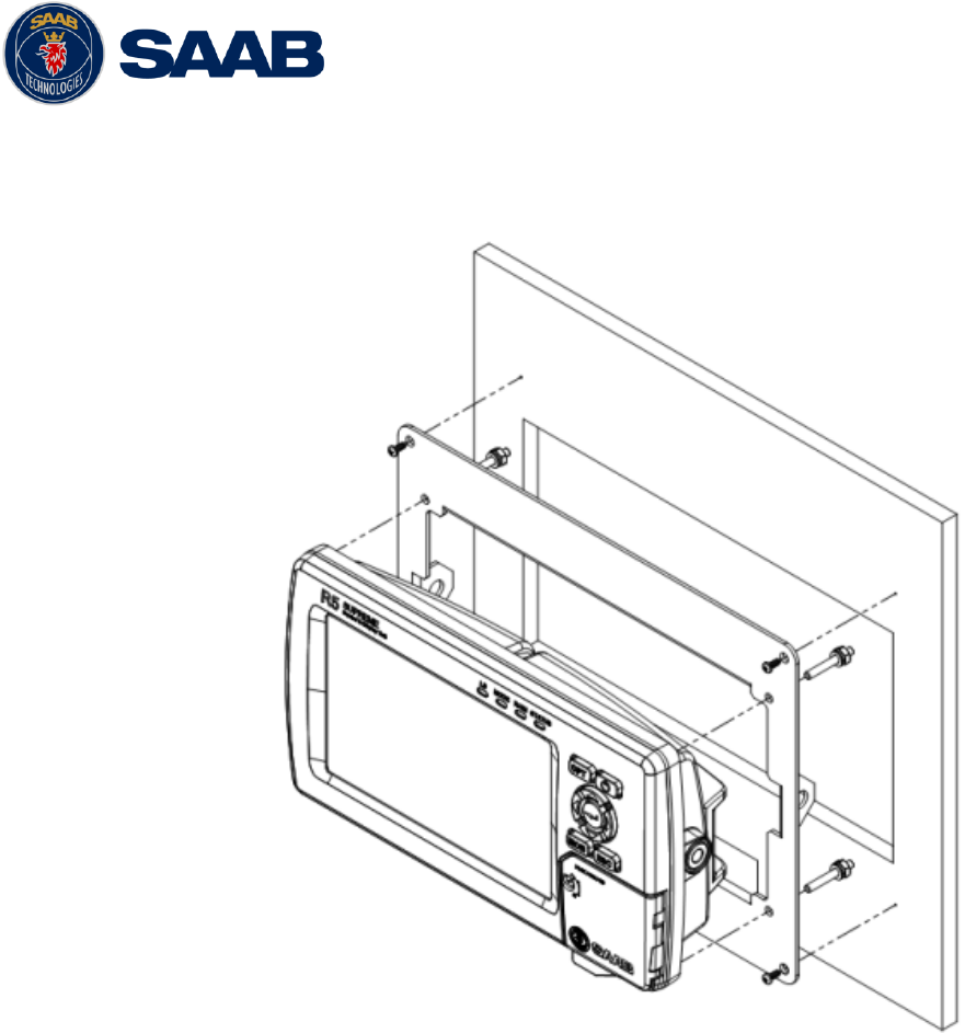
3.6.2.3 Mounting frame panel mount
The CDU can be attached to the panel mount frame using the mounting kit 7000 118-315
included with the R5 CDU.
Figure 2 – R5 SUPREME CDU, Mounting frame panel mount
The cutout dimensions may need to be increased somewhat compared to the R4 MKD
cutout, as the R5 CDU is slightly wider. See Section 13.5 CDU Mounting Frame cutout and
dimensions.
R5 SUPREME AIS System
INSTALLATION
7000 118-300, B1 Page 17
3.8 Installing the R5 SUPREME Transponder
3.8.1 Transponder Location
When mounting the R5 SUPREME Transponder, please consider the following:
Mount the unit on a wall or on top of a bench
The temperature and humidity should be moderate and stable, +15ºC to +35ºC
(Operating temperature: -15ºC to +55ºC.)
Select a location away from excessive heat sources
Avoid areas where there is a high flow of humid salt air
Avoid places with high levels of vibrations and shocks
Ensure that there is enough airflow to avoid high ambient temperatures
Ensure that the cables can be connected without violating their minimum bending
radius
The unit can affect magnetic compasses. The minimum compass safe distance is 0.65
meters to a standard magnetic compass and 0.40 meters to a steering magnetic
compass
Install the R5 SUPREME transponder as close as possible to the transponder’s
VHF/GPS antennas to minimise cable loss
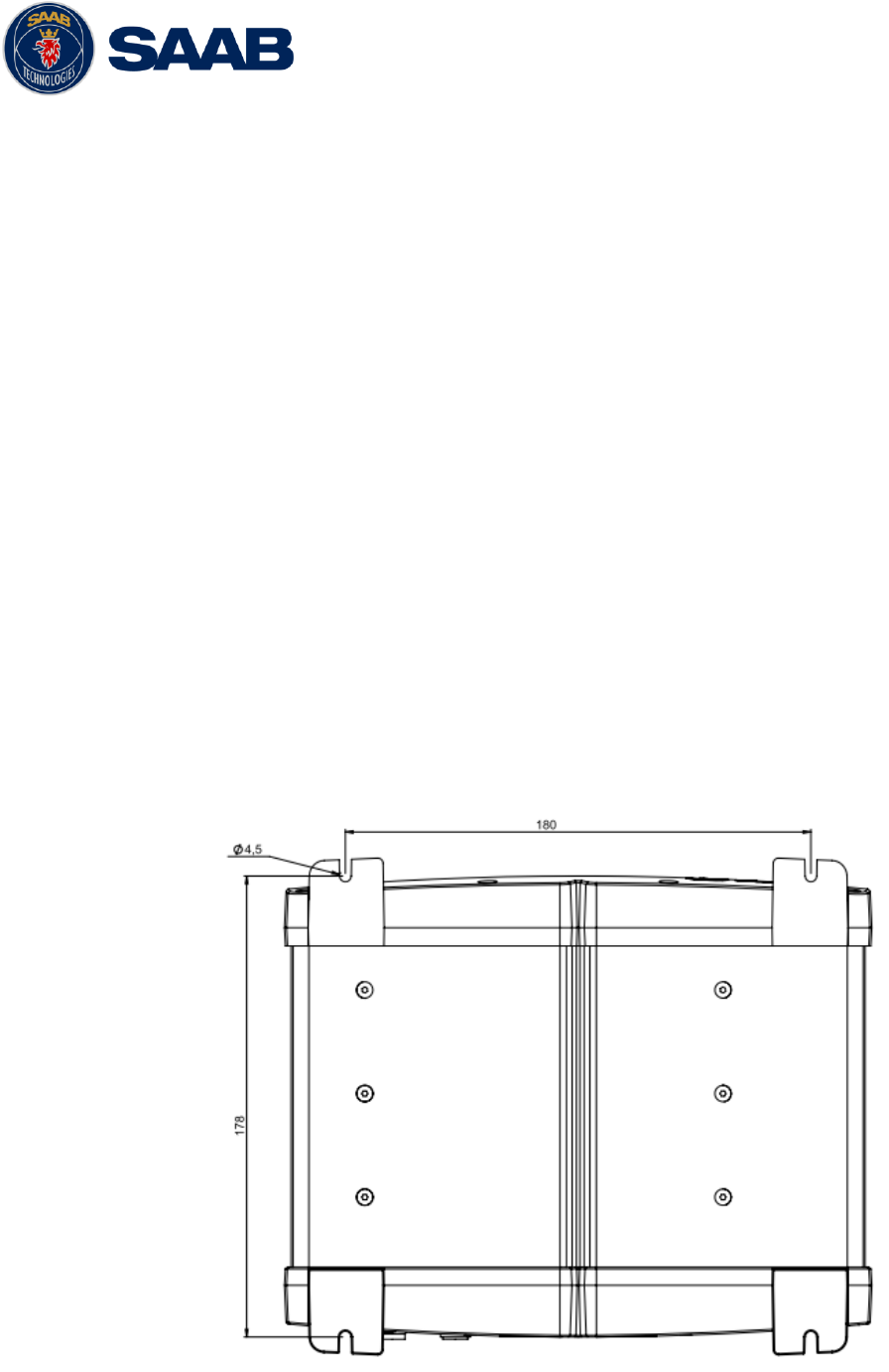
3.8.2 R5 SUPREME Transponder Mounting
The Transponder unit is secured in place using the screw holes in the four feet in the bottom
corners.
Figure 3- Transponder mounting holes.
R5 SUPREME AIS System
INSTALLATION
7000 118-300, B1 Page 18
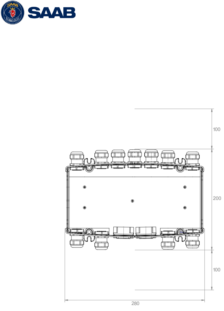
3.9 Install the R5 AIS Junction Box
3.9.1 Junction Box Location
The R5 Signal Cables connecting the transponder to the Junction box are 2m long hence this
is the maximum distance between the Junction Box and the Transponder unit.
The R5 AIS Junction Box is made from EMI shielded plastic.
Leave a clearance around the R5 AIS Junction Box to facilitate service and installation. See
below figure for minimum recommended clearance area (measurements in mm).
Figure 4 – Recommended Clearance Area (mm) for R5 AIS Junction Box
R5 SUPREME AIS System
INSTALLATION
7000 118-300, B1 Page 19
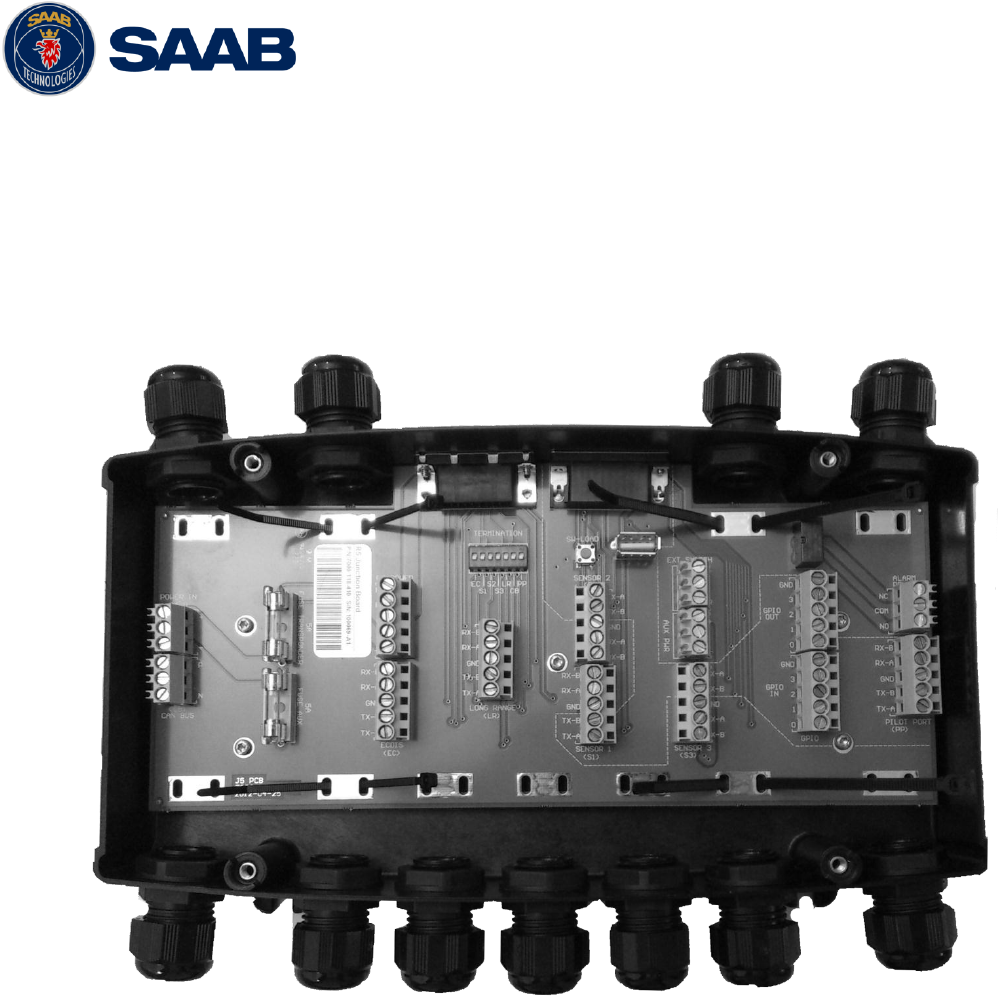
3.9.2 Junction Box Connections
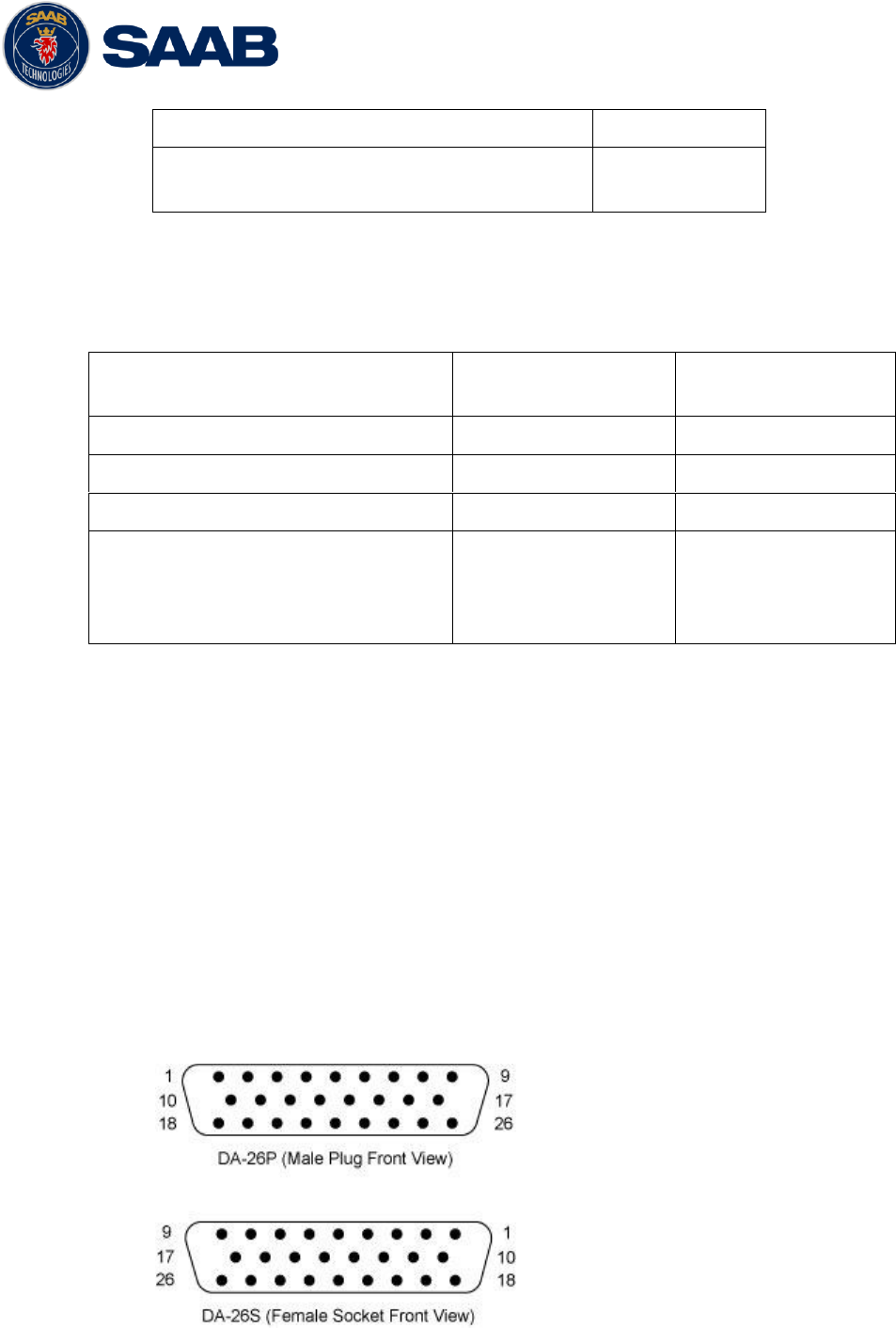
The Junction box feature two 26-pin DSUB connectors, one male and one female.
All other connectors are internal of terminal block type.
Note: The R5 AIS Junction Box has two internal 5A fuses. The first fuse protects the
connected transponder and the other one is an auxiliary fuse. The auxiliary fuse is meant to
protect any device that is connected to the auxiliary power terminal block. The CDU is an
example of such a device.
Interfaces:
Please see Section 12.2 “R5 AIS Junction box Interfaces” for details.
It is recommended to connect external cables to the Junction box before mounting the box
to a surface.
Open the lid of the R5 AIS Junction Box.
Fix the box on an appropriate surface/place with using the screw holes on the four feet of
the junction box.
Pull the cables through suitable cable glands. These glands are located on the front and
back of the junction box. Please note that the glands can be removed if the cables are too
thick. With the glands mounted, the maximum supported cable diameter is 12mm. Without
the glands mounted, the maximum supported cable diameter is 19.5mm.
Shielded cables should be stripped down to the shielding and fastened with cable ties.
There are eleven cable tie fastening points on the circuit board, one for every anti-
vibration gland on the junction box. Make sure that the cable shielding touches the tin
plated area at the fastening point. The maximum supported cable tie width is 4.5mm.

R5 SUPREME AIS System
INSTALLATION
7000 118-300, B1 Page 20
Tighten the anti-vibration glands so that the cables are secured.
Connect the cables to the terminal blocks.
Fix the lid to the box casing.
3.10 Mount the VHF Antenna
The R5 SUPREME Transponder, like any other ship borne transceiver operating in the VHF
maritime band, may cause interference to a ship’s VHF radiotelephone. Because AIS is a digital
system, this interference may occur as a periodic (e.g. every 10 second) soft clicking sound on a
ship’s radiotelephone. This effect may become more noticeable when the VHF radiotelephone
antenna is located close to the AIS VHF antenna and when the radiotelephone is operating on
channels near the AIS operating channels (e.g. channels 27, 28 and 86).
Attention should be paid to the location and installation of different antennas in order to obtain the
best possible efficiency. Special attention should be paid to the installation of mandatory
antennas like the AIS antennas.
So, installing the AIS VHF antenna is also a crucial part of the system installation. How and
where you install your AIS VHF antenna and cable will affect its efficiency.
3.10.1 VHF Antenna Location
Location of the mandatory AIS VHF antenna should be carefully considered. Digital
communication is more sensitive than analogue/voice communication to interference created
by reflections in obstructions like masts and booms. It may be necessary to relocate the VHF
radiotelephone antenna to minimize the interference effects. Installing the VHF antenna for
AIS on a vessel is a compromise between the following items:
Antenna type
Antenna separation
Clear view of the horizon
Antenna height
3.10.1.1 Antenna Type
The AIS VHF antenna should have Omni directional vertical polarization providing unity
gain.
3.10.1.2 Antenna Separation
AIS transponders use simplex channels at frequencies on the high side of the marine
mobile band (AIS channel A = 2087, 161.975 MHz, and AIS channel B = 2088, 162.025
MHz). These channels are close to the duplex channels used for shore to ship marine
communication. The AIS VHF antenna should be separated as much as possible from the
voice VHF installations used for main communication to avoid unnecessary interference.
There should not be more than one antenna on the same level. The AIS VHF antenna
should be mounted directly above or below the ship’s primary VHF radiotelephone antenna,
with no horizontal separation and with a minimum of 2 meters vertical separation. If it is
located on the same level as other antennas, the distance apart should be at least 10
meters.
The AIS VHF antenna should be installed safely away from interfering high-power radiating
sources like radar and other transmitting radio antennas, preferably at least 3 meters away
from and out of the transmitting beam.
R5 SUPREME AIS System
INSTALLATION
7000 118-300, B1 Page 21
3.10.1.3 Clear View of the Horizon
The AIS VHF antenna should be placed in an elevated position that is as free as possible
with a minimum distance of 2 meters in horizontal direction from constructions made of
conductive materials. The antenna should not be installed close to any large vertical
obstruction. The objective for the AIS VHF antenna is to see the horizon freely through 360
degrees.
3.10.1.4 VHF Antenna Height
The AIS is using VHF radio frequencies, which propagation characteristics are close to line
of sight. The higher the antenna location is, the longer the range will be.
3.10.2 VHF Cabling
The cable should be kept as short as possible to minimize attenuation of the signal. Double
shielded coaxial cable equal or better than RG214 is recommended to minimize the effects
from electromagnetic interference from high power lines, radar or other radio transmitter
cables.
The table below gives recommendation on cables that can be used for the VHF-antenna
connections. The cable attenuation shall be kept as low as possible; a 3 dB loss is the same
as cutting the signal strength in half.
Ex: A cable of 40 meter RG 214 has a cable attenuation of 2.8 dB.
3.10.3 VHF Cable Mounting
Coaxial cables should be installed in separate signal cable channels/tubes and at least 10 cm
away from power supply cables. Crossing of cables should be done at right angles (90°).
Coaxial cables should not be exposed to sharp bends, which may lead to a change of the
characteristic impedance of the cable. The minimum bending radius should be 5 times the
cable's diameter.
All outdoor installed connectors should be weather proofed, e.g. with shrink tubing, watertight
seal tape or butyl rubber tape and plastic tape sealing, to protect against water penetration into
the antenna cable.
Secure the cable properly close to the cable ends.
3.10.4 VHF Cable Grounding
Coaxial down-leads must be grounded. The coaxial shielding screen should be connected to
ground at one end.
Type
Attenuation @ 150
MHz (dB/100m)
(mm)
Weight (kg/100m)
RG 214
7
10.8
18.5
RG 217
5
13.8
30.1
RG 225
8
10.9
23.3
Table 5 – VHF Antenna Cables

R5 SUPREME AIS System
INSTALLATION
7000 118-300, B1 Page 22
3.11 Mount the GPS Antenna
The R5 SUPREME shall be connected to a GPS antenna type MA-700, AT575-68 or a combined
AC Marine GPS/VHF antenna. 5V DC is supplied through the antenna lead for the antenna
preamplifier.
If the combined AC Marine GPS/VHF antenna is used the diplexer unit shall be installed in an
indoors environment.
Attention should be paid to the location and installation of the different antennas on the ship in
order to obtain the best possible efficiency. Special attention should be paid to the installation of
mandatory antennas like the AIS antennas.
So, installation of the GPS antenna is a crucial part of the system installation. How and where
you install your GPS antenna and cable will greatly affect its sensing efficiency.
3.11.1 GPS Antenna Location
The GPS antenna must be installed where it has a clear view of the sky. The objective is to
see the horizon freely through 360 degrees with a vertical observation of 5 to 90 degrees
above the horizon. Small diameter obstructions, such as masts and booms do not seriously
degrade signal reception, but such objects should not eclipse more than a few degrees of any
given bearing. Do not mount the antenna in the top of a mast or tower, as this may degrade
the COG and SOG readings.
Locate the GPS antenna at least 3 meters away from and out of the transmitting beam of high-
power transmitters such as S-Band Radar (typically 15° vertically from the array’s centre
point) and/or Inmarsat systems (A, B, C, or M; typically 10º from the array’s centre point in
any of the possible transmitting directions).
Locate the GPS antenna at least 3 meters away from HF or VHF radios or their antennas. This
includes the ship’s own AIS VHF antenna if it is designed and installed separately.
3.11.2 GPS Cabling
The gain of the GPS antenna built-in pre-amplifier shall match the cable attenuation. The
resulting installation gain (pre-amplifier gain minus cable attenuation) shall be within 0 to 26
dB. A minimum value of 10 dB is recommended for optimum performance.
Double shielded coaxial cable is recommended. The coaxial cable should be routed directly
between the GPS antenna and the R5 SUPREME Transponder’s GPS connector in order to
reduce electromagnetic interference effects. The cable should not be installed close to high-
power lines, such as radar or radio-transmitter lines or the AIS VHF antenna cable. A
separation of 1 meter or more is recommended to avoid interference due to RF-coupling.
Crossing of antenna cables should be done at 90 degrees to minimise magnetic field coupling.
The table below gives recommendation on cables that can be used for the Transponder GPS-
antenna connections. Due to the high frequency it’s important that the attenuation in the cable
is low for the specific frequency (1.5 GHz).
R5 SUPREME AIS System
INSTALLATION
7000 118-300, B1 Page 23
Type
Attenuation @ 1.5
GHz (dB/m)
(mm)
Weight (kg/100m)
RG 58
0.9
5
3.7
RG 400
0.6
4.95
6.3
RG 223
0.6
5.40
5.5
RG 214
0.35
10.8
18.5
RG 225
0.3
10.9
23.3
Table 6 – GPS Antenna Cables
For optimum performance approximately +10dB gain should be available when the cable
attenuation has been subtracted from the GPS-antenna preamplifier gain. The net gain shall
not exceed +26dB.
Example:
Cable type
Preamplifier
gain (dB)
Required min. cable
length (m)
Recommended
max. cable length
(m)
RG 58
12
0
2
RG 58
26
0
18
RG 58
30
4.5
22
RG 223
12
0
3.5
RG 223
26
0
26.5
RG 223
30
6.5
33.5
RG 214
12
0
6
RG 214
26
0
46
RG 214
30
11.5
57
Table 7 – GPS Antenna Cable Examples
Min length = (Preamp. Gain – 26 dB)/Cable attenuation per meter
Max length = (Preamp. Gain – 10 dB)/Cable attenuation per meter
3.11.3 GPS Cable Mounting
Coaxial cables should be installed in separate signal cable channels/tubes and at least 10 cm
away from power supply cables. Crossing of cables should be done at right angles (90°).

R5 SUPREME AIS System
INSTALLATION
7000 118-300, B1 Page 24
Coaxial cables should not be exposed to sharp bends, which may lead to a change of the
characteristic impedance of the cable. The minimum bending radius should be 5 times the
cable's diameter.
All outdoor installed connectors should be weather proofed, e.g. with shrink tubing, watertight
seal tape or butyl rubber tape and plastic tape sealing, to protect against water penetration into
the antenna cable.
Secure the cable properly near the cable ends.
3.11.4 GPS Cable Grounding
Coaxial down-leads must be used. The coaxial shielding screen should be connected to
ground at one end.
3.12 Electrical Installation details
For complete specification of signal interface details see Section 12 “Electrical Interfaces”
3.12.1 Input port priority
The protocol of the serial port interfaces is compliant to IEC 61162-1Ed.4 (2010-11).
All serial ports in the R5 SUPREME Transponder have the same capabilities with one
exception, any Long Range equipment must be connected to the Long Range port. Apart from
that, all ports are bidirectional ports and can be connected to any external equipment such as
ECDIS and external sensors. The primary external position sensor should be connected to the
Sensor 1 port since this port has the highest priority. The serial ports in the R5 SUPREME
Transponder can also receive differential corrections in RTCM format for the internal GPS
receiver. The ports in the R5 SUPREME Transponder have different default baud rates but
they can all be configured to any baud rate of 4800, 9600, 38400, 57600 or 115200 bps. The
priority levels for input of sensor data on the different ports are listed below:
Priority
Identification
Default Baud Rate
1
(Highest priority)
Sensor 1
4800 bps
2
Sensor 2
4800 bps
3
Sensor 3
4800 bps
4
ECDIS
38400 bps
5
Long Range
9600 bps
6
Transponder Pilot
38400 bps
7
(Lowest priority)
CDU Pilot
38400 bps
Table 8 – Port Priorities and Default Baud Rates
If valid position data from external position sources are input on both Sensor 1 and ECDIS
port, the position data from Sensor 1 will be used.
R5 SUPREME AIS System
INSTALLATION
7000 118-300, B1 Page 25
If the same data is provided using different NMEA sentences on the same port, the priority
depends on the sentence in accordance with Table 9.
Priority
Position
COG/SOG
HDG
ROT
1
(Highest)
RMC
RMC
THS
ROT
2
GNS
VTG
HDT
-
3
GGA
VBW
OSD
-
4
GLL
OSD
-
-
Table 9 – Sentence priority
3.12.2 Output Drive Capacity for Serial Ports
Each serial port transmitter can have a maximum of 25 listeners drawing 2.0 mA each.
3.12.3 Input Load
Input impedance for each listener input is 6.4 kΩ.
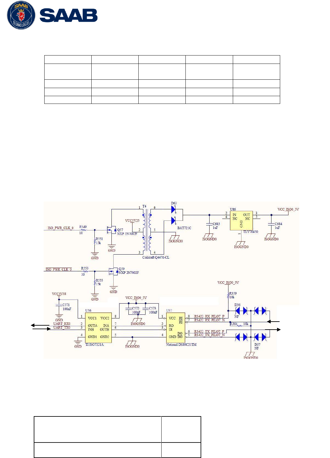
3.12.4 Schematics of Serial Transceivers
Each of the RS422 serial interfaces fulfils the requirements of IEC 61162-2 and IEC 61993-2.
A detailed schematic of one of the serial ports is shown below.
3.12.5 Discrete Input/Output Signals (GPIO)
The R5 SUPREME Transponder has four discrete input signals and four discrete output
signals which are used in e.g. R5 SUPREME W-AIS installations. These GPIO signals have
the following capacities:
High-level input voltage
(will be interpreted as logical “1” if above)
2.1 V
Low-level input voltage
0.9 V
ISO Power
Internal
Signals to R5
SUPREME
Transponder
To connected
equipment
Figure 5 – Serial Port Schematics

R5 SUPREME AIS System
INSTALLATION
7000 118-300, B1 Page 26
(will be interpreted as logical “0” if below)
High-level output voltage
(shall be interpreted as logical “1”)
Min 2.48 V
Max 3.38 V
Low-level output voltage
(shall be interpreted as logical “0”)
Max 0.5 V
Maximum Output Current
4 mA
3.12.6 Transponder Connections
Connect Ethernet cable to network or directly to R5 SUPREME CDU Ethernet port.
Connect R5 Power Cable to R5 AIS Junction box.
Connect CDU and Transponder Ground terminals to ship ground.
Connect one R5 Signal Cable to Transponder RS422 port and R5 AIS Junction box.
Connect one R5 Signal Cable in opposite direction to Transponder I/O port and R5
AIS Junction box.
Connect GPS antenna to GPS port and VHF antenna to VHF port
Note: The I/O port gender is opposite from the RS422 port, and the R5 Signal cable is Male to
Female. This will ensure the wrong transponder port is not connected to the wrong junction box
DSUB port.
3.12.7 CDU Electrical Connections
Connect Ethernet cable to network or directly to R5 SUPREME Transponder Ethernet
port.
Connect R5 Power Cable to Junction box or other External power with 5A Fuse.
Connect Ground terminal to ship ground.
3.12.8 R5 AIS Junction box connections
Figure 1 show a general overview how the R5 SUPREME AIS System can be connected to
the R5 AIS Junction Box. For a more detailed description of the cable connections, see section
3.3 Installation Cables.
3.12.8.1 R5 System general connections
Connect External power to the POWER IN.
Connect R5 Power cable from R5 Transponder to R5 POWER terminal
Connect R5 Power cable from R5 CDU to AUX PWR terminal (optional)
Note: R5 CDU can be mounted in a remote location and use another power source.
Connect R5 Signal Cables from R5 Transponder I/O and RS422 ports to Junction box
DSUB connectors.
Note: Both the R5 SUPREME Transponder’s 26-pin interface ports (marked RS-422 and I/O) should
be connected to the R5 AIS Junction Box by using two R5 Signal Cables, DSUB-DSUB.

R5 SUPREME AIS System
INSTALLATION
7000 118-300, B1 Page 27
3.12.8.2 External connections
Connect external sensor providing GPS Position (mandatory)
Connect external sensor providing True Heading, and Rate of Turn if available.
Connect: DGPS Beacon receiver providing RTCM-104 format data to any of the RS-422
input screw terminals
R5 SUPREME AIS System
INSTALLATION
7000 118-300, B1 Page 28
3.12.9 External Switch
It is possible to connect an external switch to the R5 SUPREME Transponder. This switch may
be used to quickly turn off transmissions.
If the silent switch functionality is to be used, the parameter “External Switch” must be
configured to “Silent Switch” in Misc. Interface view accessed from Main Menu
Maintenance
Configuration
Interface
Misc. Interfaces.
The status of the switch can be controlled by input on the brown and orange wires of the R5
Power Cable ( See section 3.3 for cable details ), or by connecting to the R5 AIS Junction Box
(R) and (F) signals in the Ext Switch terminal block.
Connect the external switch as in the figure below. When the switch is open, all VHF
transmissions will be disabled.
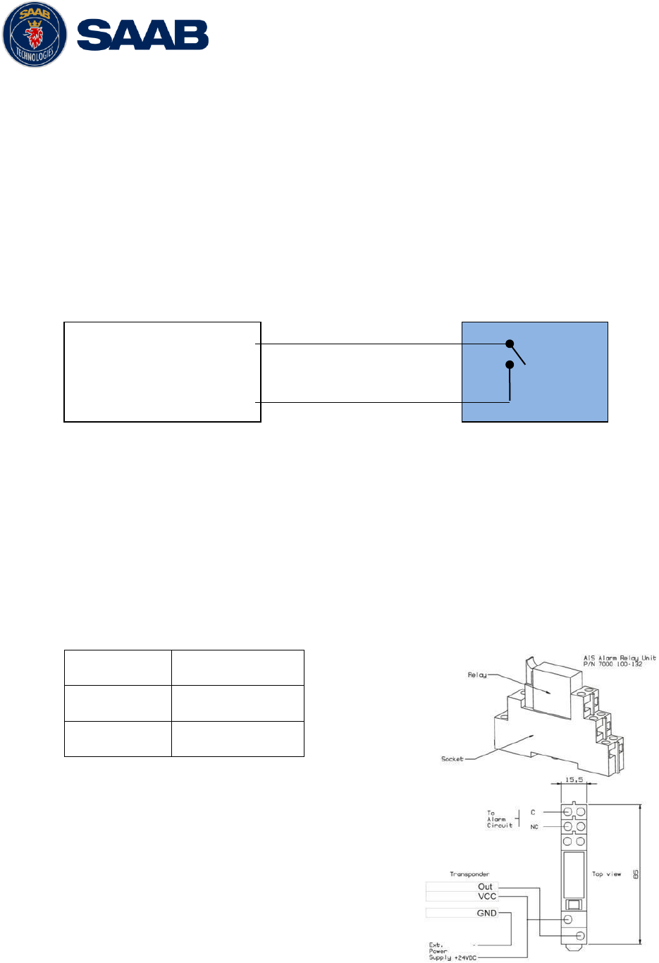
3.12.10 Alarm Relay
It is required that the AIS alarm output (relay) is connected to an audible alarm device or the
ship’s alarm system, if available. The R5 AIS Junction Box has a built in alarm relay that can
be connected to the ship’s alarm system. If the installation is done without the junction box, an
external alarm relay should be connected.
Alternatively, the ship’s BIIT alarm system may use the alarm messages output on the AIS
Presentation Interface (PI) provided the alarm system is AIS compatible. The AIS Alarm Relay
is either mounted on a DIN mounting rail or direct on the wall.
The alarm relay wires have the following colour codes in the 26-pole R5 signal cable:
RELAY VCC
Brown / Red
RELAY GND
White / Pink
RELAY OUT
Pink / Brown
Table 10 – Alarm Relay Wires
Figure 6 – Alarm Relay
External
Switch
Ext Switch (R)
Ext Switch (F)

R5 SUPREME AIS System
INSTALLATION
7000 118-300, B1 Page 29
R5 SUPREME AIS System
CONFIGURATION
7000 118-300, B1 Page 30
4 CONFIGURATION
When the physical and electrical installation of the system is complete, the R5 SUPREME AIS
System needs to be configured. This chapter describes what the installer is required to do before the
R5 SUPREME AIS System is fully functional.
4.1 Configuration Wizard
The first time the R5 SUPREME CDU is started, a configuration wizard will be shown. This wizard
is a helpful guide to configure the basic functionality of the R5 SUPREME System. The following
sections describe the different steps in the configuration wizard.
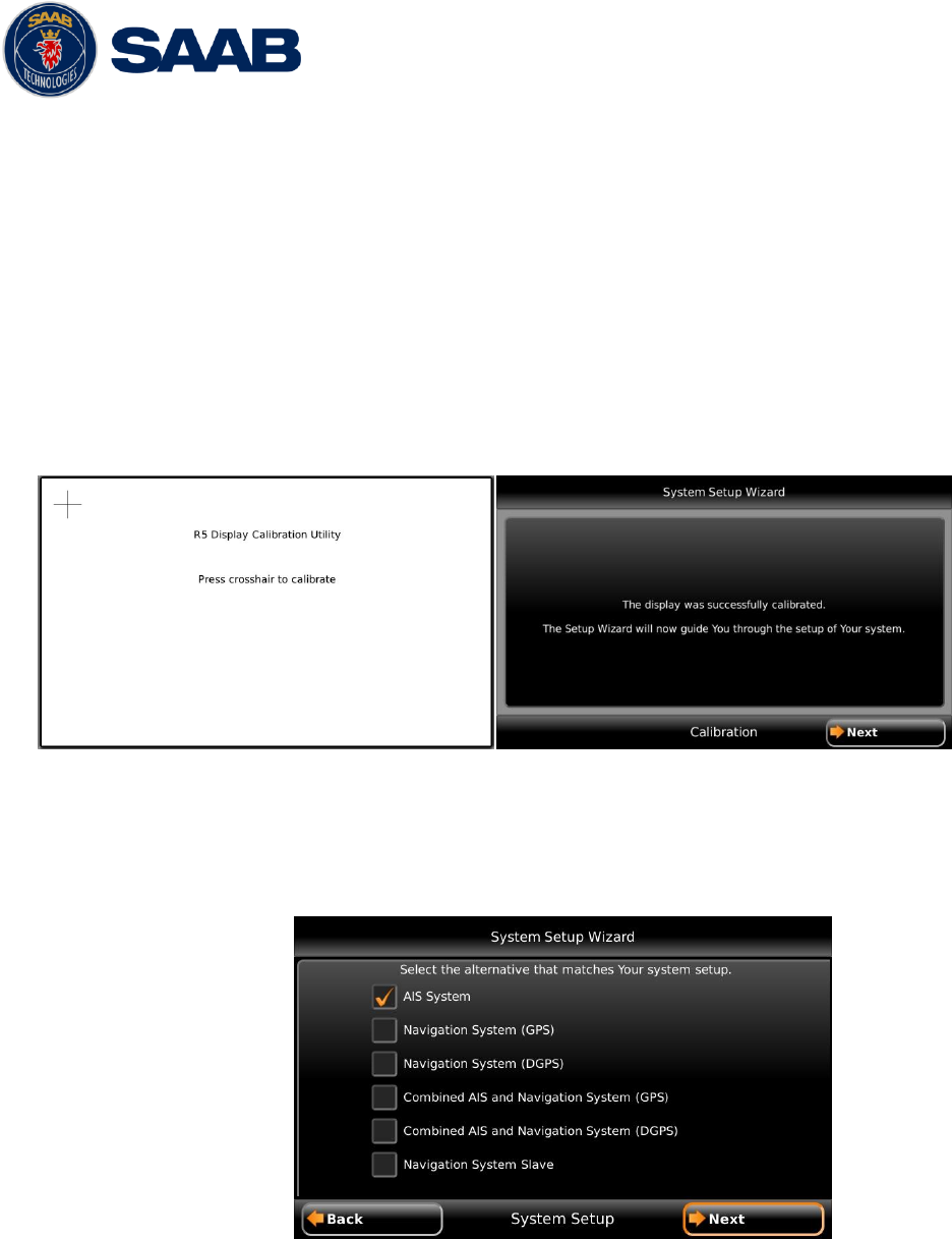
4.1.1 Calibration Screen
The first time the R5 SUPREME CDU is used, the touch screen needs to be calibrated. A
cross will be shown on the screen at five different locations. Press on the cross each time it
appears to calibrate the touch screen. Try to hit the centre of the cross as accurate as possible
for the best possible calibration.
4.1.2 System Setup
The R5 SUPREME CDU can be used in a standalone AIS system, standalone Navigation
system, Combined AIS and Navigation system or be used as a slave display to an existing R5
Navigation System. The Navigation system can also be in two different configurations with
either an R4 GPS sensor or an R4 DGPS sensor. It is up to the user to specify which
equipment is connected to the R5 SUPREME CDU.
In a standard AIS installation, the alternative “AIS System” should be selected.
R5 SUPREME AIS System
CONFIGURATION
7000 118-300, B1 Page 31
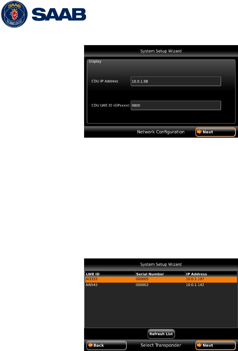
4.1.3 Network Configuration
The R5 SUPREME CDU uses UDP Multicast as defined by IEC 61162-450 Light Weight
Ethernet (LWE), to communicate with the R5 SUPREME Transponder as well as other R5
SUPREME CDU units. It is therefore necessary to configure an IP number and a Light Weight
Ethernet network ID for the R5 SUPREME CDU. The LWE ID consists of two letters (always
“GP” for the R5 SUPREME CDU) and four digits.
The IP and LWE ID must be unique for all equipment connected to the LWE network.
4.1.4 Select Transponder
When the R5 SUPREME CDU is configured to be used in an AIS system, an R5 Transponder
must be located and selected on the LWE network. Make sure that the R5 Transponder has
power and is connected to the same network as the R5 SUPREME CDU. In the “Select
Transponder” view on the R5 SUPREME CDU, press the button “Refresh List” to search for
R5 Transponders on the network. Select the R5 Transponder that the R5 SUPREME CDU
should communicate with and press “Next” to go to the Transponder Network Configuration
view.
R5 SUPREME AIS System
CONFIGURATION
7000 118-300, B1 Page 32
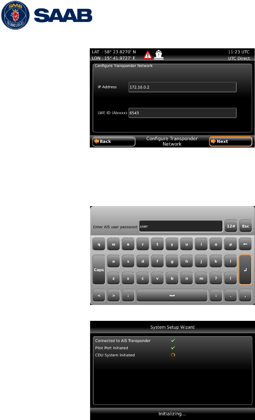
4.1.5 Transponder Network Configuration
When a transponder has been selected by the R5 SUPREME CDU it is possible to configure
the transponder IP address and LWE ID. The R5 SUPREME Transponder must have a unique
LWE ID that consists of two letters (always “AI” for an R5 Transponder) and four digits. Press
“Next” to save changes and finish the configuration wizard.
The R5 Transponder IP address and LWE ID configuration is password protected. The default
AIS user password is “user” and the password is case sensitive.
4.1.6 Connection Screen
This screen is shown while the R5 SUPREME CDU connects to external equipment and
initializes the system. When the initialization is complete the R5 SUPREME CDU will
automatically switch to the Target List view when configured as an AIS system.
R5 SUPREME AIS System
CONFIGURATION
7000 118-300, B1 Page 33
4.2 System Functional Check
When the R5 SUPREME has been installed according to the procedures described in previous
chapters, it is recommended to make a first functional check of the system. Check the following
things to ensure that the R5 SUPREME AIS System is fully functional.
Check the Own Ship Data view to make sure that the configured data is sent on the VHF
link, refer to chapter 5.10 “View Transmitted Own Ship Information” for more information.
Make sure that there are no unexpected active alarms in the alarm list, see chapter 5.16
“Alarms”.
Perform a communication test to ensure that the R5 SUPREME transponder can send and
receive messages from other AIS transponders. Refer to chapter 5.23 “Communication Test” for
information on how to perform a communication test.
4.3 Configuration Parameters
This section describes the different configuration parameters that can be set in the R5 SUPREME
AIS System.
4.3.1 AIS Voyage
This view is accessed by pressing Main Voyage AIS Voyage.
The parameters in AIS Voyage view are used for input of voyage specific information that is
sent over the AIS link. These parameters should typically be configured before each voyage.
Parameter Name
Description
Navigational Status
Changes the navigational status reported by own ship.
It is also possible to quickly change navigational status
by pressing Nav. Status Icon in the status bar.
Estimated Time of Arrival (ETA)
The estimated time of arrival to destination of current
voyage
Destination
The destination for the current voyage
Draught (Class A)
The vertical distance measured from the lowest point of
a ship’s hull to the water surface, in meters (one
decimal precision)
Hazardous Cargo (X,Y,Z,OS)
Classification of current cargo according to X,Y,Z,OS
Persons on Board
Total number of persons on board
4.3.2 Ship Static
This view is accessed by pressing Main Maintenance Configuration AIS Ship
Static
Parameter Name
Description
R5 SUPREME AIS System
CONFIGURATION
7000 118-300, B1 Page 34
MMSI
Maritime Mobile Service Identity reported by own ship
IMO
International Maritime Organization number reported by
own ship
Ship Name
Ship name reported by own ship
Call Sign
Call sign reported by own ship
Height over Keel
Height over keel in meters (one decimal precision).
Height over Keel information is sent as a response to
an “Extended Ship Static and Voyage Related Data”
request message.
Ship Type (IMO)
Type of Ship according to ITU 1371-4. Both numerical
input and selection from list is possible.
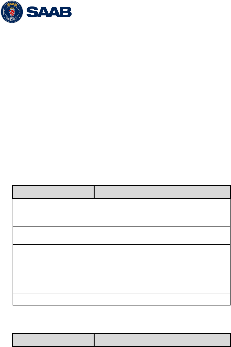
4.3.3 Ship Dimensions
This view is accessed by pressing Main Maintenance Configuration AIS Ship
Dimensions
The parameters in the Ship Dimensions view depends on the configuration parameter “Ship
Size Mode” in the Misc. Interfaces view. The Ship Size Mode parameter can be set to either
Standard or Simplified (default). The Ship Size Mode affects how the user should input ship
size and antenna position information and how it is interpreted.
Standard Mode
In this mode the user must input:
A, B, C, D for internal antenna [m]
A, B, C, D for external antenna [m]
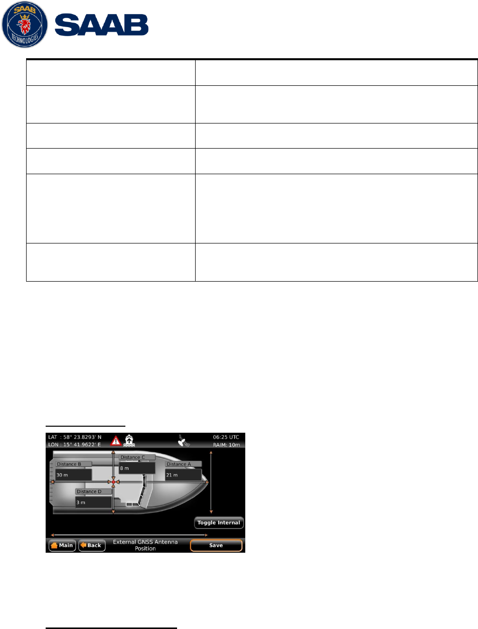
Simplified Mode (default)
In this mode there is no way for the user to input mismatching data, all parameters uses the
same precision and each measurement is entered only once (in standard mode it is for
example possible to enter three different length of ship: Convoy/ship length, internal A+B and
external A+B). In simplified mode the transponder will automatically calculate and correctly
round the A, B, C and D values reported on the VHF link.
R5 SUPREME AIS System
CONFIGURATION
7000 118-300, B1 Page 35
In this mode the user inputs:
Ship length [m] (one decimal precision)
Ship beam [m] (one decimal precision)
X, Y for internal antenna relative to ship [m] (one decimal precision)
X, Y for external antenna relative to ship [m] (one decimal precision)
4.3.4 Regional Areas
This view is accessed by pressing Main Maintenance Configuration AIS VHF
Radio Regional Areas
The view shows the regional areas set in the transponder. These are normally transmitted by
an AIS base station to change AIS VHF nominal power level and/or frequencies in a specific
area. When editing an area or creating a new area the following parameters can be
configured:
Parameter Name
Description
Channel A
The channel number for AIS channel A (2087 = default)
that should be used in the regional area
Channel B
The channel number for AIS channel B (2088 = default)
that should be used in the regional area
Zone Size
The transitional zone size of the regional area in
nautical miles (NM)
Tx Mode
Decides on which channels the transponder will use
when transmitting in the regional area.
When set to “Silent”, the transponder will stop
automatic transmissions on AIS channels A and B.
Power
Output power for the transponder in the regional area.
High = 12.5 W, Low = 1 W.
LAT NE
The latitude for the North East corner of the regional
area
LON NE
The longitude for the North East corner of the regional
area
R5 SUPREME AIS System
CONFIGURATION
7000 118-300, B1 Page 36
LAT SW
The latitude for the South West corner of the regional
area
LON SW
The longitude for the South West corner of the regional
area
4.3.5 Long Range Broadcast Configuration
This view is accessed by pressing Main Maintenance Configuration AIS VHF
Radio Long Range Broadcast
Long range messages (Message 27) are position messages designed to aid Satellite reception
of AIS position messages. AIS Satellites have a huge antenna footprint, and can have
problems with receiving too many targets at the same time. Therefore Message 27 is a slightly
shortened position messages, transmitted less frequently than normal position messages, and
on frequencies different from normal AIS VHF data.
Parameter Name
Description
LR Broadcast Ch. 1
The first channel number for broadcasting long range
message 27. The message is sent every 6 minutes on
each channel so if both channels are configured a
message 27 will be broadcast every 3 minutes. If this
parameter is set to zero no long range broadcast
transmissions will be sent on this channel.
LR Broadcast Ch. 2
The second channel number for broadcasting long
range message 27. The message is sent every 6
minutes on each channel so if both channels are
configured a message 27 will be broadcast every 3
minutes. If this parameter is set to zero no long range
broadcast transmissions will be sent on this channel.
4.3.6 Long Range (Reply Mode and Filter Settings)
This view is accessed by pressing Main Maintenance Configuration AIS Long
Range
Parameter Name
Description
Reply Mode
When set to “Auto” the R5 SUPREME Transponder will
automatically respond to any Long Range interrogation
messages.
When set to “Manual” the operator is responsible for
sending a response or refusal to any Long Range
interrogation message. This can be done from the Long
Range view that is accessed from Main Menu
Messages Long Range. For more information see
section 5.14 Long Range Interrogations.
The information that is sent in a response is
automatically filled in by the R5 SUPREME
Transponder depending on the Long Range filter

R5 SUPREME AIS System
CONFIGURATION
7000 118-300, B1 Page 37
settings (the parameters below).
Ship ID (A)
Filter setting that defines if a Long Range response
message should include ship name, call sign and IMO
number.
Message Date/Time (B)
Filter setting that defines if a Long Range response
message should include information about date and
time of message composition.
Latitude / Longitude (C)
Filter setting that defines if a Long Range response
message should include position.
Course Over Ground (E)
Filter setting that defines if a Long Range response
message should include COG.
Speed Over Ground (F)
Filter setting that defines if a Long Range response
message should include SOG.
Destination And ETA (I)
Filter setting that defines if a Long Range response
message should include destination and ETA.
Draught (O)
Filter setting that defines if a Long Range response
message should include draught.
Ship Type And Cargo (P)
Filter setting that defines if a Long Range response
message should include ship type and cargo
information.
Ship Size And Type (U)
Filter setting that defines if a Long Range response
message should include ship’s length, beam and type.
Persons On Board (W)
Filter setting that defines if a Long Range response
message should include number of persons on board.
4.3.7 Password
This view is accessed by pressing Main Maintenance Configuration AIS
Password
Parameter Name
Description
New User Password
Changes the user level password for the R5
SUPREME AIS System.
The default user level password is “user”
New Admin Password
Changes the admin level password for the R5
SUPREME AIS System.
The default admin level password is “admin”
Restore Password Key
It is possible to restore both user password and admin
password to the default values above with a secret
R5 SUPREME AIS System
CONFIGURATION
7000 118-300, B1 Page 38
restore key.
To obtain the restore key, contact TransponderTech
Support and be prepared to provide the serial number
of the transponder unit.
4.3.8 Display Parameters
This view is accessed by pressing Main Maintenance Configuration Display
Display Parameters
Parameter Name
Description
Plot Compass
This parameter determines how the plot of AIS targets
should be oriented.
If set to “North Always Up”, the plot will always have
north up and own ship will rotate according to heading
input.
If set to “Own Ship Bow Always Up”, the plot will always
have own ship pointing up and rotate the rest of the plot
according to heading input.
Require Text Msg ACK
This parameter determines if an ACK msg is required
as a response when sending addressed binary text
messages to another target.
4.3.9 Visual Settings
The backlight for the LCD, LED’s and the buttons of the R5 SUPREME CDU can be controlled
manually or automatically using the light sensor on the front of the CDU.
The default value of the LCD backlight is 80% which corresponds to approximately 550 Cd/m2.
To quickly turn off all backlight on the R5 SUPREME CDU, press once on the PWR button on
the front of the CDU. This will completely turn off all backlight for the LCD; LED’s and buttons
on the R5 SUPREME CDU.
However, if there is an active, unacknowledged alarm in the system, the STATUS LED will still
be visible and blink with a red light. To return to previous light settings, press the PWR button
again.
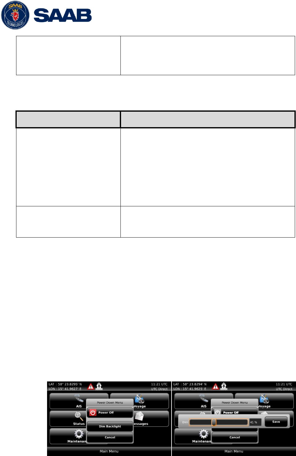
It is also possible to quickly change the overall brightness level by changing the “Master Level”
parameter value. This can be done from the Visual Settings view or by holding down the PWR
button for 2 seconds. This will enable the PWR button options menu, press “Dim Backlight” to
set the percentage value for the backlight of the LCD, LED’s and buttons. The “Dim Backlight”
button is only available when the dimming mode is set to “Manual” in the Visual Settings view.
R5 SUPREME AIS System
CONFIGURATION
7000 118-300, B1 Page 39
Figure 7 – Power Down Menu
To switch between automatic or manual dimming mode and to fine tune backlight for buttons,
LCD and LEDs, enter the Visual Settings view which is accessed from Main Menu
Maintenance Configuration Display Visual Settings
Parameter Name
Description
Dimming Mode
If set to “Manual”, the LCD backlight, button illumination
and LED intensity are controlled by the user with the
parameters described below.
If set to “Automatic”, the LCD backlight, button
illumination and LED intensity will automatically be
controlled with the light sensor on the front of the R5
SUPREME CDU. The less ambient light registered by
the light sensor, the lower percentage of backlight and
brightness will be used.
Master Level
The master level controls the overall brightness level in
percent of the selected maximum level for LCD
backlight, LED intensity and button illumination.
This parameter is only available when the “Dimming
Mode” parameter is set to “Manual”.
This parameter can also be changed by holding down
the PWR button on the front of the R5 SUPREME CDU
and then press the button “Dim Backlight”.
LCD Backlight
Controls the maximum LCD backlight level in percent.
LED Intensity
Controls the maximum LED intensity level in percent.
Button Illumination
Controls the maximum button illumination level in
percent.
4.3.10 Sound
This view is accessed by pressing Main Maintenance Configuration Display
Sound
Parameter Name
Description
Alarm Volume
Sets the volume of the R5 SUPREME CDU internal
speaker.
Alarm Waiting For ACK
Determines how the R5 SUPREME CDU speaker
should behave when an alarm is active and waiting for
acknowledgement. This setting does NOT affect the
behaviour of the alarm relay or any external alarm
system.
Long Range Message
Controls the behaviour of the R5 SUPREME CDU
speaker when an LR interrogation message is
R5 SUPREME AIS System
CONFIGURATION
7000 118-300, B1 Page 40
received.
AIS Message
Controls the behaviour of the R5 SUPREME CDU
speaker when a SRM or binary text message is
received.
4.3.11 Time
This view is accessed by pressing Main Maintenance Configuration Display
Time
Parameter Name
Description
Time Zone
This parameter defines if the times that are displayed in
the R5 SUPREME CDU should be in UTC or LOC
(local) time. If local time is chosen, the offset from UTC
must be specified with the three parameters listed
below.
Offset sign
The sign of the local time offset from UTC.
Hours
The local time hour offset from UTC.
Minutes
The local time minute offset from UTC.
4.3.12 Units
This view is accessed by pressing Main Maintenance Configuration Display
Units
Parameter Name
Description
Range Unit
This parameter determines the unit for the range value
of targets in the Target List, Extended Info view and
Plot view. Range values can be calculated in nautical
miles (NM), kilometres (km) or statute miles (Sm).
Speed Unit
This parameter determines the unit for the SOG value
of targets in Extended Info view and Plot view. The
SOG values can be calculated in knots (kn), kilometres
per hour (km/h) or miles per hour (mph).
4.3.13 CDU Password
This view is accessed by pressing Main Maintenance Configuration Display
CDU Password
Parameter Name
Description
New CDU Password
Changes the password for the R5 SUPREME CDU.
The default CDU password is “cdupwd”
Restore Password Key
It is possible to restore the CDU password to the
R5 SUPREME AIS System
CONFIGURATION
7000 118-300, B1 Page 41
default value above with a secret restore key.
To obtain the restore key, contact TransponderTech
Support and be prepared to provide the serial number
of the R5 SUPREME CDU unit.
4.3.14 Alarm Config
This view is accessed by pressing Main Maintenance Configuration Alarms
In this view all alarms can be configured to either “Enabled” or “Disabled”. When the alarm is
enabled, an active alarm will affect the external alarm relay as well as the speaker in the R5
SUPREME CDU. It will also be shown as a popup alarm in the CDU. When the alarm is set to
disabled it will not affect anything when the alarm becomes active.
For more information about the alarm view, refer to chapter 5.16 “Alarms”. For a list of all the
alarms that can occur, refer to chapter 8.3 “Troubleshooting with Alarm Messages.”
4.3.15 Port Rates
In the Port Rates view it is possible to configure the baud rate for all the serial ports of the R5
SUPREME Transponder and the Pilot Port on the R5 SUPREME CDU. It is also possible to
specify if checksum is required for data sent to the specific port.
This view is accessed by pressing Main Maintenance Configuration Interface
Port Rates
Parameter Name
Description
Baud Rate
Changes the baud rate (bits per second) for the
corresponding serial port.
Checksum
When set to “Required”, all messages that are input on
the corresponding serial port to the R5 SUPREME
Transponder must have a valid checksum.
When set to “Disabled”, messages both with and
without checksum are accepted on the corresponding
serial port.
4.3.16 Misc Interfaces
This view is accessed by pressing Main Menu Configuration Interface Misc
Interfaces
Parameter Name
Description
SSD Password
Changes the value of the SSD password level. When
set to “None”, no password is required when
configuring the transponder with an SSD sentence from
e.g. an ECDIS via the serial port interface.
When set to “User”, an SPW sentence with the correct
user level password must be sent before the SSD on
the serial port interface.
R5 SUPREME AIS System
CONFIGURATION
7000 118-300, B1 Page 42
Ship Size Mode
This affects how the user should input the ship size,
convoy size and antenna positions. See section 4.3.3
for more details.
AIS GPS Output Port
Defines on which serial port the R5 SUPREME should
output data from the internal GPS. When set to “None”
no internal GPS data will be output.
External Switch
This parameter specifies if there is an external silent
switch connected to the system.
If no switch is used, set the parameter to “No Function”.
See section 3.12.9 “External Switch” for more
information.
System Mode
May be used to determines if the R5 SUPREME should
operate as a Class A transponder or in other modes
that may be available in the future. This will not be
available in all systems. Contact SAAB
TransponderTech for information.
This parameter will affect what configuration
parameters and menus are visible in the system.
4.3.17 Own CDU Settings (Network)
This view is accessed by pressing Main Menu Configuration Interface Network
Own CDU Settings
Parameter Name
Description
CDU IP Address
The Internet Protocol (IP) address of the R5 SUPREME
CDU.
CDU LWE ID
The unique ID that is used on the Light Weight Ethernet
network. For example if this parameter is set to “3141”
the R5 SUPREME CDU will transmit messages on the
LWE network with the LWE ID “GP3141”.
This ID must be unique for all equipment connected to
the same LWE network.
4.3.18 Transponder Settings (Network)
This view is accessed by pressing Main Menu Configuration Interface Network
Transponder Settings
Parameter Name
Description
IP Address
The Internet Protocol (IP) address of the R5 SUPREME
Transponder.
LWE ID
The unique ID that is used on the Light Weight Ethernet
network. For example if this parameter is set to “3142”
R5 SUPREME AIS System
CONFIGURATION
7000 118-300, B1 Page 43
the R5 Transponder will transmit messages on the
LWE network with the LWE ID “AI3142”.
This ID must be unique for all equipment connected to
the same LWE network.
4.3.19 Transponder LWE Input (Network sensors)
This view is accessed by pressing Main Menu Configuration Interface Input
Transponder LWE Input
Configuration in this view allows for connection of GNSS, heading and ROT equipment to the
R5 Supreme transponder using the LWE interface.
For each data type, enter the LWE ID for each external system that the Transponder shall
connect to. For example if Primary position source is set to “GP3210” the R5 SUPREME
Transponder will accept position data on the LWE network from systems with the LWE ID
“GP3210”.
Parameter Name
Description
Position Primary Source
Set to LWE ID of primary position source
Position Secondary Source
Set to LWE ID of secondary position source
COG + SOG Primary Source
Set to LWE ID of primary COG + SOG source
COG + SOG Secondary Source
Set to LWE ID of secondary COG + SOG source
Rate of Turn Primary Source
Set to LWE ID of primary Rate of Turn source
Rate of Turn Secondary Source
Set to LWE ID of secondary Rate of Turn source
Heading Primary Source
Set to LWE ID of primary Heading source
Heading Secondary Source
Set to LWE ID of secondary Heading source
4.3.20 Installation Test
This view is accessed by clicking Main Menu Maintenance Installation Test
Parameter Name
Description
AIS Position Source
This parameter specifies which port the R5 SUPREME
Transponder should use as its external position source.
The default value of this parameter is “Automatic”
which means that the R5 SUPREME Transponder will
accept position information on any port and use the
information on the port with highest priority.
If Position Source is set to anything other than
“Automatic”, the R5 SUPREME Transponder will only
accept position information if it comes from the port
specified by this parameter.

R5 SUPREME AIS System
CONFIGURATION
7000 118-300, B1 Page 44
SART Test Mode
This parameter determines if SART Test targets should
be displayed in Target List and Plot views of the R5
SUPREME CDU.
It also controls if connected systems, for example
ECDIS, will receive SART Test targets.
R5 SUPREME AIS System
OPERATION
7000 118-300, B1 Page 45
5 OPERATION
5.1 General usage
The system can be fully operated using the R5 SUPREME CDU. The CDU is operated using the
touch sensitive screen, or the backlit keypad. Some ECDIS systems may also allow for normal
AIS usage.
Apart from observing received AIS targets, normal interfacing with the system involves:
Updating voyage related parameters
Updating navigational status
Verifying alarms
Sending/receiving text messages.
The CDU Front hatch covers an integrated AIS Pilot Plug connector. This hatch can be locked
shut if needed. We recommend a flat tip 5.5-6.5mm screwdriver for locking/unlocking the hatch.
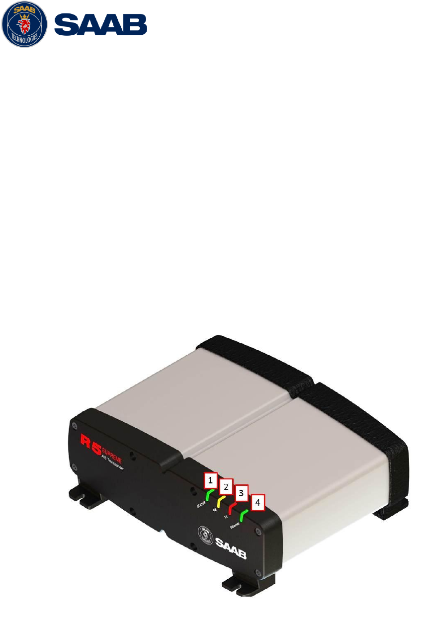
5.2 LED’s on R5 SUPREME Transponder
1 - STATUS LED (multi-colour)
Constant green when the transponder is operating and no alarms are active.
Constant red if there is an active alarm.
Flashing red if there is an unacknowledged alarm.
2 - RX LED (yellow)
R5 SUPREME AIS System
OPERATION
7000 118-300, B1 Page 46
Flashes yellow when the transponder receives a message on the VHF link.
3 - TX LED (red)
Flashes red when the transponder transmits a message on the VHF link.
4 - Ethernet LED (green)
Constant green when an Ethernet cable is connected
Flashes green when data is transferred.
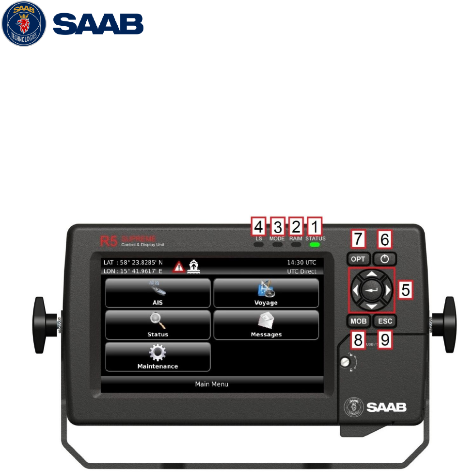
5.3 LED’s and Controls on R5 SUPREME CDU
This section describes the controls and status LED’s on the front of the R5 SUPREME CDU.
1 - STATUS LED (multi-colour)
Constant green when the transponder is operating and no alarms are active
Constant red if there is an active alarm
Flashing red if there is an unacknowledged alarm
2 - RAIM LED (multi-colour)
Not used in standard R5 SUPREME AIS System. Only used in Navigation System enabled
installations.
3 - MODE LED (multi-colour)
Not used in standard R5 SUPREME AIS System. May be used in other product variants, see
product variant specific documentation.
4 - LIGHT SENSOR
Can be used to automatically dim the backlight of the display, see section 4.3.9 Visual Settings.
5 - ARROW KEYPAD and ENTER
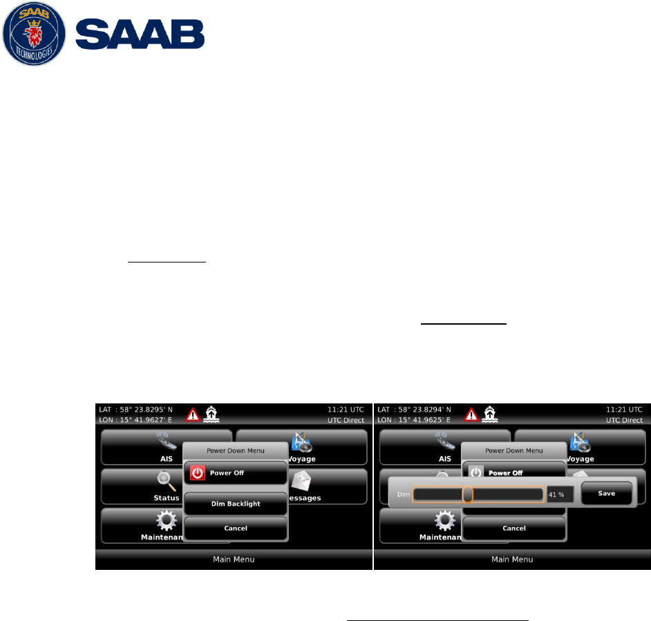
R5 SUPREME AIS System
OPERATION
7000 118-300, B1 Page 47
The easiest way to navigate in menus, lists and edit fields in the R5 SUPREME CDU is by using
the touch interface. However, the arrow keypad and ENTER button can also be used to control
the R5 SUPREME CDU in e.g. rough seas. The arrow keypad (< > and ∧ ∨) is used to navigate in
menus, lists and edit fields. The centre button of the keypad is an ENTER button which is used to
select the highlighted choice in a menu, list or edit control.
6 - PWR
The power button on the R5 SUPREME CDU is used to turn off the display and can also be used
to quickly change the settings for backlight of LCD, buttons and LEDs.
A quick press of the PWR button will turn off all backlight but the R5 SUPREME CDU
will still be running. If there is an active, unacknowledged alarm in the system, the
STATUS LED will still be blinking red. Otherwise all LED’s will be turned off.
If the PWR button is pressed for more than two seconds, a “Power Down Menu” will
appear. Here it is possible to power off the R5 SUPREME CDU completely or to
quickly change the backlight percentage for the LCD, LEDs and buttons if Dimming
Mode is set to “Manual” (see section 4.3.9 for information about Dimming Mode
parameter).
Figure 8 – Power Down Menu
If the PWR button is pressed for more than fifteen seconds, the CDU will perform a
hard reboot.
7 - OPT
This button is an “Option key” which is only active in some of the views. When pressed, it gives
the user a list of options that can be performed on the highlighted item.
In screens with parameters, the OPT button can be used to set the parameter to default value.
8 - MOB
Not used in the plain R5 SUPREME AIS System. Only available in Navigation System enabled
installation.
9 - ESC
Used to return to previous screen or to cancel an edit change of a data field.
5.3.1 Change Settings of a Parameter
Several of the views in the R5 SUPREME CDU contain parameters that can be edited. To edit
a parameter, click on it using the touch interface. A virtual keyboard will appear where it is
possible to enter data. Click on the enter button of the virtual keyboard when the data input is
done. To save all the changes made in the current view, press the Save button in the lower
right corner of the screen.
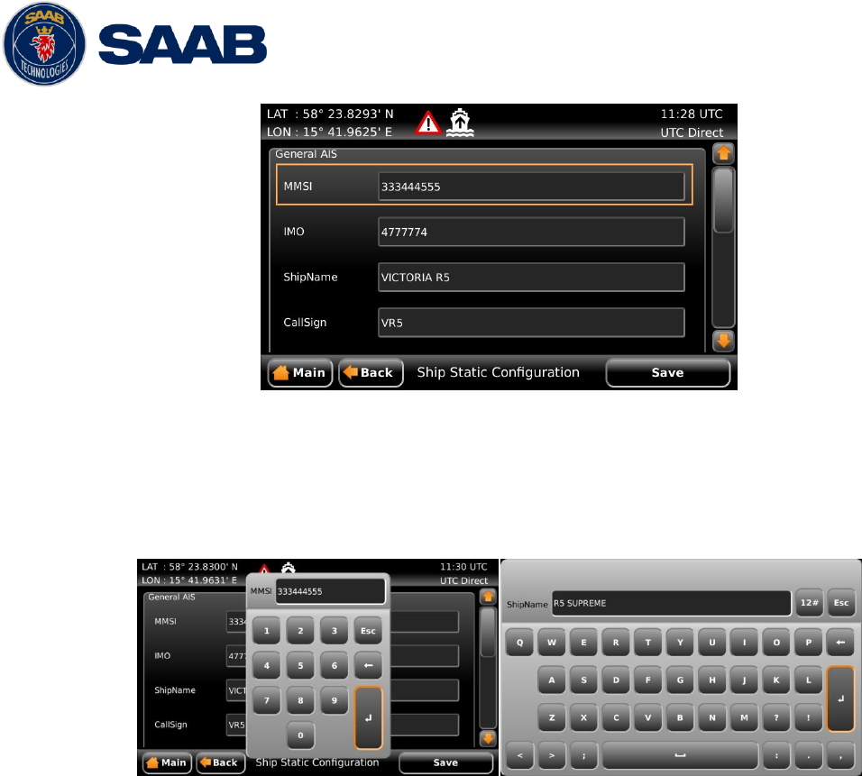
R5 SUPREME AIS System
OPERATION
7000 118-300, B1 Page 48
Figure 9 – Example of a parameter view
It is also possible to use buttons on the front of the R5 SUPREME CDU to select and change a
parameter. Use the ARROW KEYPAD to select a parameter, the currently selected parameter
will be marked with an orange rectangle (see figure above). Press ENTER to popup the virtual
keyboard. Use the ARROW KEYPAD to highlight the desired character and press ENTER to
select it. Navigate to enter button of the virtual keyboard and press ENTER when done.
Figure 10 – Example of virtual keyboards
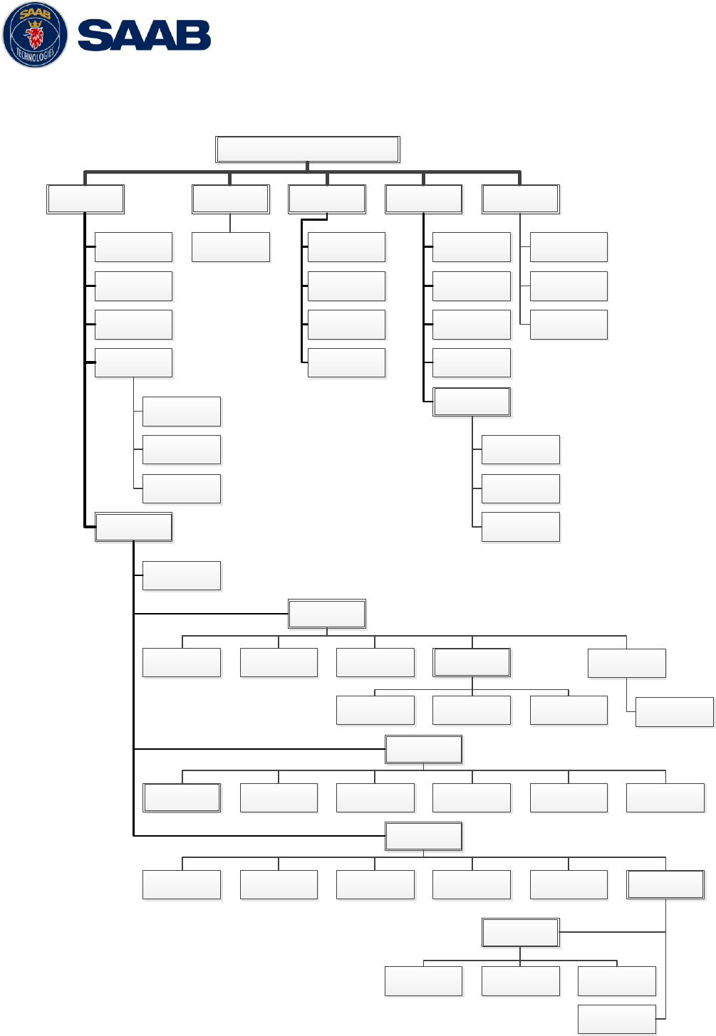
R5 SUPREME AIS System
OPERATION
7000 118-300, B1 Page 49
5.4 Menu Structure – Tree view
Main menu
AIS
Operational Mode
Own ship data
Plot
Target List
Maintenance
Communication Test
Configuration
AIS
Display ParametersLong Range PasswordShip Dimensions Ship Static VHF Radio
Long Range
Broadcast
Regional Areas
Edit Area New AreaView Area
Alarm
Display
Visual Settings Calibrate Display CDU PasswordSoundTime Units
Interface
Misc Interfaces Network
Own CDU SettingsSelect Transponder
Transponder
Settings
Port Rates System Setup
Installation Test
Factory Reset
System Update
Update CDU SW
Messages
AIS Messages
Long Range Msg
Persons on Board
Status
AIS Status
AIS Internal GPS
Status
Non Functional Time
VHF Status
Alarm List
Status List
SW/HW Info
View Raw Data
Voyage
Ais Voyage
Update Transponder
SW
Update Licenses
Input
Transponder LWE
Input
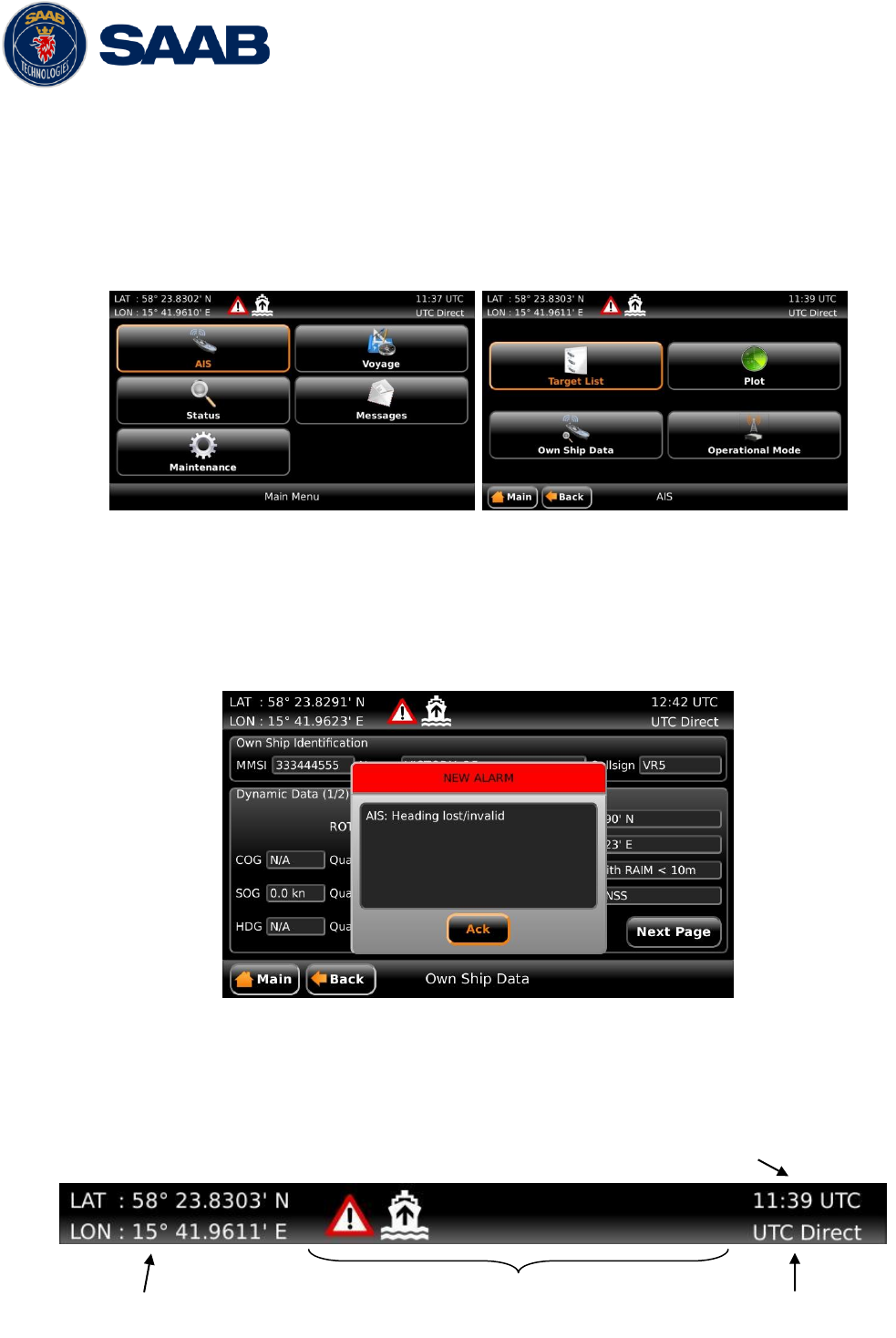
R5 SUPREME AIS System
OPERATION
7000 118-300, B1 Page 50
5.4.1 Navigating in Menus
To navigate in the R5 SUPREME CDU menus, simply press the menu button corresponding to
the desired view using the touch interface, or use the ARROW KEYPAD buttons < > and ∧ ∨
to navigate between the view buttons. The currently selected button will be marked with an
orange outline and orange text. Press the ENTER button to enter the currently selected view.
In the lower left corner of a view there is also a Back button to quickly go back to previous view
and a Main button to go directly to the Main Menu view.
Figure 11 – Main Menu Figure 12 – AIS Menu
5.5 Alarm and Alert Pop-ups
The R5 SUPREME AIS System features alarm and alert pop-ups that can appear any time during
operation. To acknowledge an alarm or alert message, click the ACK button using the touch
screen or press ENTER. An example of an alarm message is shown below.
Figure 13 – Alarm Popup
5.6 Status Bar
The top of the screen of the R5 SUPREME CDU always displays a summary of the system’s
status. See illustration below.
Current position
Status icons
Current
synchronization state
Current time

R5 SUPREME AIS System
OPERATION
7000 118-300, B1 Page 51
If a valid navigation position is available, it is displayed to the left. The status icons are displayed
in the middle and the current time is shown to the right. Time is either UTC or local (LOC).
Beneath the current time there is also information about the transponder’s synchronization state.
The synchronization state can be:
UTC Direct – This is the normal state where the R5 SUPREME Transponder gets the
UTC time from its own internal GPS receiver.
Indirect Synchronization – The R5 SUPREME Transponder is synchronizing based on
receipt of data from other AIS transmitters.
NOTE: It is possible to be in Indirect Synchronization but still have a valid position in the
upper left corner of the status bar. The position information may be from an external GPS
sensor, but UTC Direct synchronization can only be taken from the internal GPS receiver.
5.7 Status Icons
The status icons that can be displayed are:
Unread message (safety related message, text message or RTA)
Unread Long Range message (automatic reply)
Unread Long Range message (manual reply)
Active alarms – Press for quick access to alarm list
1W mode (Indicates 1 Watt TX mode for Tankers is enabled.) See NOTE below for
details.
Silent Mode activated, either with Tx Mode parameter or silent switch.
Navigational status, being one of:
Navigational status is undefined
At anchor or moored
Under way using engine
Navigational status is one of: Not under command, Restricted manoeuvrability,
Constrained by her draught, Aground, Engaged in fishing, Under way sailing, Reserved
for future use.
Press the Navigational Status icon for quick access to the NavStatus selection view.
NOTE: The transponder will automatically engage 1W mode when the following conditions are
met: Ship type = Tanker, Nav Status = Moored and SOG <= 3 knots, otherwise 1W mode will
be automatically disengaged. The Tanker 1W mode is fully automatic and cannot be
disengaged by other external control.
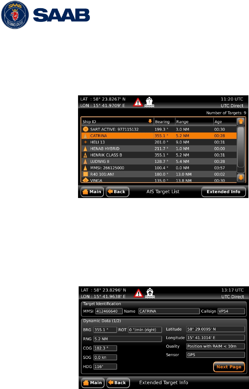
R5 SUPREME AIS System
OPERATION
7000 118-300, B1 Page 52
5.8 View Remote Ship Information
The R5 SUPREME AIS System will power up in Target List view. This view is accessed from
Main Menu AIS Target List.
The Target List view displays a list of all AIS targets received on the VHF link. The list includes
MMSI or ship’s name (Ship ID), range (RNG), bearing (BRG) and time since last report was
received (Age) for each AIS target received by the system.
Figure 14 – Target List
For extended information about a target in the list, select the desired target in the list and then
press the “Extended Info” button. When using the ARROW KEYPAD, use the ∧ ∨ buttons to
select the target list (marked with an orange frame) and press ENTER. It is now possible to use
the ∧ ∨ buttons to select the desired target in list. The press ESC and use the ARROW KEYPAD
to navigate to the “Extended Info” button. Press ENTER to entemailbr the Extended Information
view.
The Extended Information view includes static, dynamic and voyage related data for the selected
target. Press the button “Next Page” to switch between the pages of extended information.
Figure 15 – Extended Info
It also is possible to press OPT button in Extended Info view to query for Static And Voyage Data and
Persons on Board information.
Press “Back” button in the lower left corner to return to Target List view.
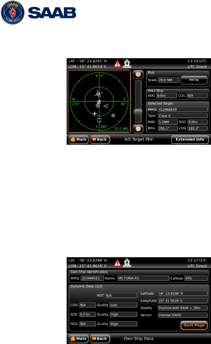
R5 SUPREME AIS System
OPERATION
7000 118-300, B1 Page 53
5.9 View Plot of Targets
The location of targets relative to your own ship is visualized in the Plot view. The view is
accessed from the Main Menu AIS Plot.
Figure 16 – Target Plot
For extended information about a target select it in the plot and press the “Extended Info” button
in the lower right corner.
The own ship target is displayed as a ‘T’ shaped symbol. Class B targets are indicated by a ‘B’
appended to the target icon and Inland targets are indicated by either an ‘I’ or by a blue sign
symbol appended to the target.
5.10 View Transmitted Own Ship Information
The information transmitted by the R5 SUPREME Transponder on the VHF link is viewed in the
Own Ship Data view. This view is accessed from Main Menu AIS Own Ship Data and
includes the static, dynamic and voyage related data actually sent by the R5 SUPREME
Transponder. The view reflects the contents of the last transmitted AIS messages, thus there
may be some delay from the time the parameters are changed until they are displayed in the
Own Ship Data view.
Figure 17 – Transmitted Own Ship Data
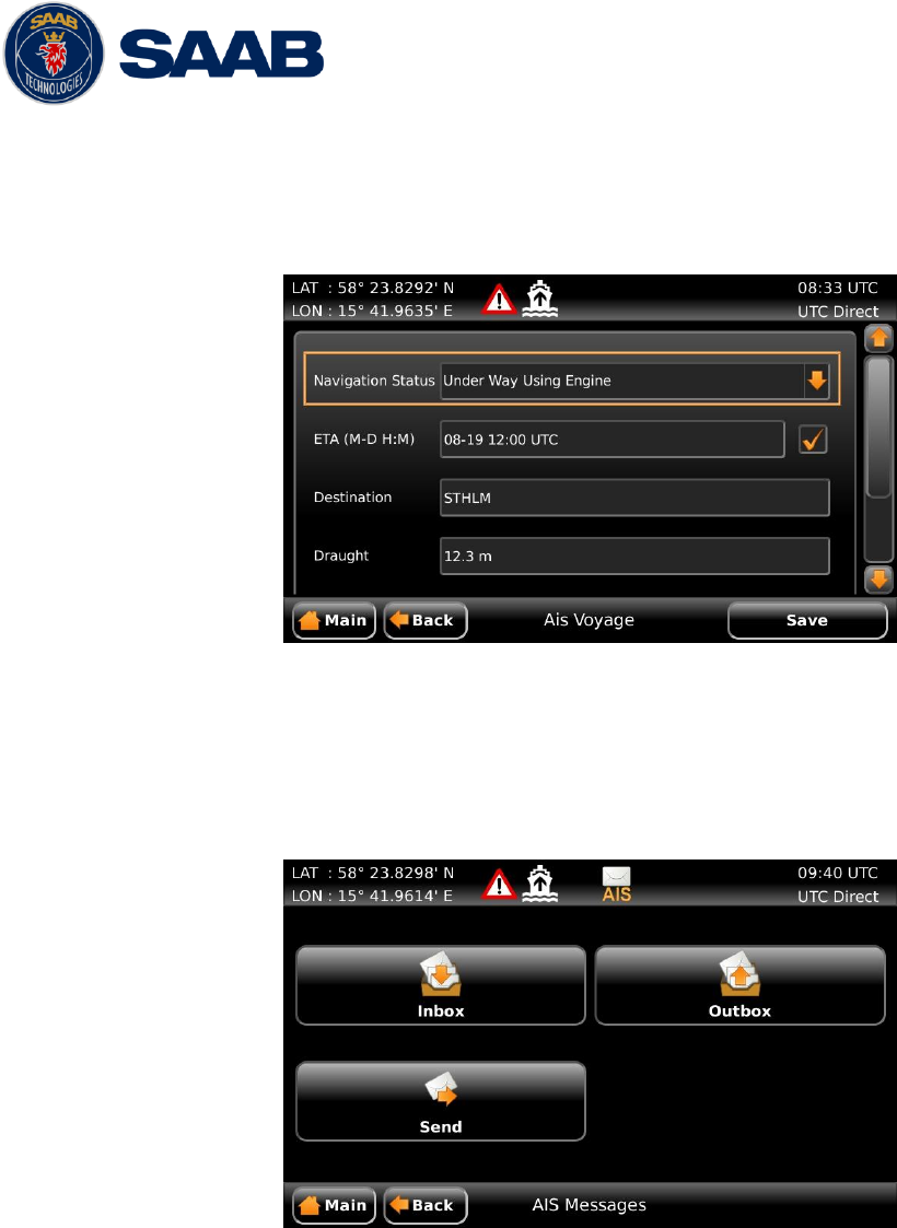
R5 SUPREME AIS System
OPERATION
7000 118-300, B1 Page 54
5.11 Enter and Read Voyage Related Information
Voyage related information (for transmit via AIS) is displayed in the AIS Voyage view. The view is
accessed from Main Menu AIS VoyageAIS Voyage. Voyage related data includes
destination, estimated time of arrival (ETA) and number of people aboard.
Figure 18 – AIS Voyage
5.12 Handling Safety Related Messages (SRM) and Text Messages
Safety related messages (SRMs) and text messages can be sent to specific targets (addressed
messages) or broadcast to all targets. The Inbox, Outbox and Send views for SRMs and text
messages can be accessed from Main MenuMessagesAIS Messages.
Figure 19 - AIS Messages
5.12.1 Read Received Messages
Received messages can be accessed in the Inbox view. Unread SRMs and text messages are
indicated with an envelope icon in the status bar. In the Inbox view unread messages are
marked with a closed envelope while read messages are marked with an open envelope.
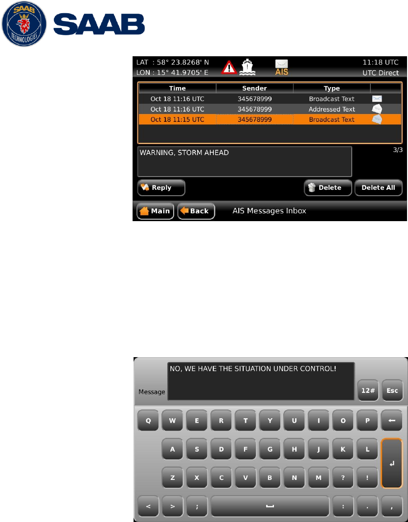
R5 SUPREME AIS System
OPERATION
7000 118-300, B1 Page 55
Figure 20 – AIS Message Inbox
5.12.2 Send SRMs and Text Messages
SRMs are composed and sent in the Send view accessed from Main Menu Messages
AIS Messages Send. It is also possible to select a target in the Target List view or the Plot
view and press the OPT key to address a message to a specific unit.
To write a message, click in the text edit area to the left or use the ARROW KEYPAD to mark
the text area and press ENTER. This will show the virtual keyboard where the message can
be entered. Click on the ENTER button of the virtual keyboard when done.
Figure 21 – Virtual Keyboard
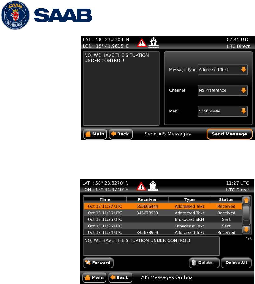
R5 SUPREME AIS System
OPERATION
7000 118-300, B1 Page 56
Figure 22 – AIS Message Send view
Sent messages can be viewed in the Outbox view accessed from Main Menu Messages
AIS Messages Outbox.
Figure 23 – AIS Message Outbox
5.13 Send Persons On Board
In the Persons On Board view it is possible to send information about number of persons on
board (PoB) to another vessel. The PoB message can be sent as either addressed or broadcast.
The information sent in the messages is automatically filled in by the R5 SUPREME AIS System
depending on the voyage configuration made in Main MenuVoyageAIS Voyage.
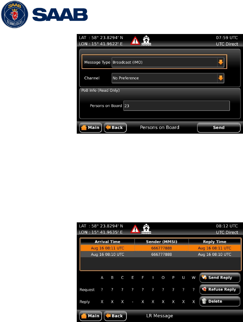
R5 SUPREME AIS System
OPERATION
7000 118-300, B1 Page 57
Figure 24 – Persons On Board
5.14 Long Range Interrogations
An AIS transponder can receive long range interrogation messages to poll for certain information.
A received interrogation message is indicated by a LR icon in the status bar. If the “Long Range
Reply Mode” parameter has been configured to “Auto”, the R5 SUPREME Transponder will
automatically send a response to the interrogation. If the “Long Range Reply Mode” parameter is
set to “Manual”, the operator must send a response or refusal from the Long Range Message
view accessed from Main Menu Messages Long Range. For more information about the
“Reply Mode” parameter and Long Range filter settings, see section 4.3.6.
Figure 25 – Long Range
To send a reply or refusal to the interrogation or to delete an interrogation from the message list,
click on the message in the list view to mark it and then click on one of the buttons “Send Reply”,
“Refuse Reply” or “Delete”. When using the ARROW KEYPAD, use the buttons ∧ ∨ to navigate
to the message list and press ENTER. Mark the desired interrogation by again using ∧ ∨ and then
press ESC button to be able to navigate to the desired button using the ARROW KEYPAD (∧ ∨,
< >). Press ENTER when the desired button is marked with orange frame and orange text (see
“Send Reply” button in picture above).
The Long Range view uses the following symbols to indicate the status of a request or reply
message:
? – The information is requested by the sender
X – The information is available and provided
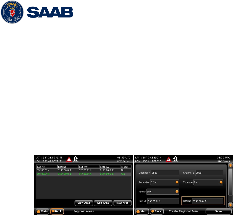
R5 SUPREME AIS System
OPERATION
7000 118-300, B1 Page 58
! – The information requested is refused
5.15 Regional Areas
Regional Area messages are transmitted from shore based AIS Base Stations by local authorities
to control AIS VHF settings of AIS transponders within a defined area. The transponder will store
up to eight different areas. An area will timeout and be deleted 24 hours after it was last received,
or if the distance to the area becomes greater than 120 NM.
All regional areas that are stored in the R5 SUPREME Transponder can be viewed in the
Regional Areas view which is accessed from Main Menu Maintenance Configuration
AIS VHF Radio Regional Areas. The list shows the north east and south west corners of
the areas. The area is marked with green colour if it is in use by the R5 SUPREME Transponder.
To view the settings of an area or to edit an existing area, mark the area in the list and click on
the “View Area” or “Edit Area” button. When using the ARROW KEYPAD, mark the area list and
then press ENTER to be able to select the desired area with ∧ ∨. When the correct area is
selected, press ESC and use the ARROW KEYPAD to navigate to the desired button.
It is possible to manually create and edit regional areas in the system. It is not recommended to
modify anything in this view unless instructed to do so by the authorities or for testing in a
controlled environment.
Figure 26 – Regional Areas
5.16 Alarms
All currently active and enabled alarms are shown in the Alarm List view that can be accessed
from Main Menu Status Alarm List or by clicking on the alarm indication in the status bar.
As default, only alarms that are configured as “Enabled” will be shown in the list. It is possible to
also show disabled active alarms by pressing the button “Show All Alarms”. For a list of all
alarms, see chapter 8.3.
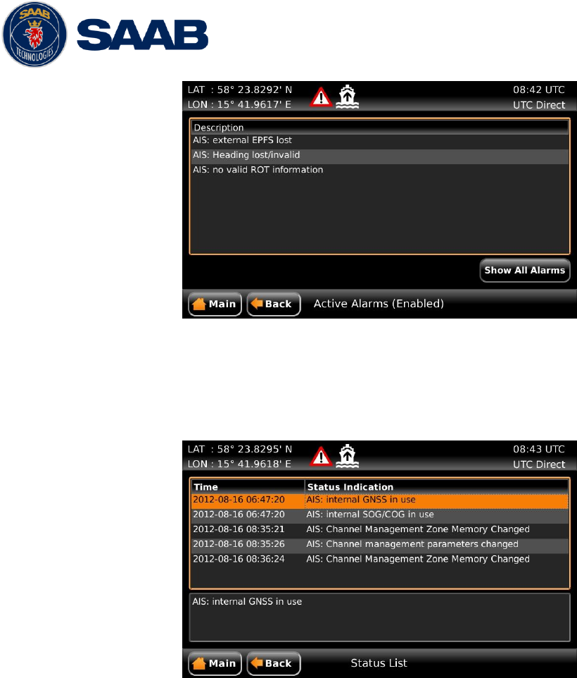
R5 SUPREME AIS System
OPERATION
7000 118-300, B1 Page 59
Figure 27 - Alarms
5.17 Status List
Current status indications are listed in the Status List view that can be accessed from Main Menu
Status Status List. The different status indications that can occur are listed in chapter 8.8.
Figure 28 - Status List
5.18 Non Functional Time
This view displays information about times when the R5 SUPREME Transponder has been
turned off or for some other reason has not been transmitting for more than 15 minutes. The view
is accessed from Main Menu Status AIS Non Functional Time.
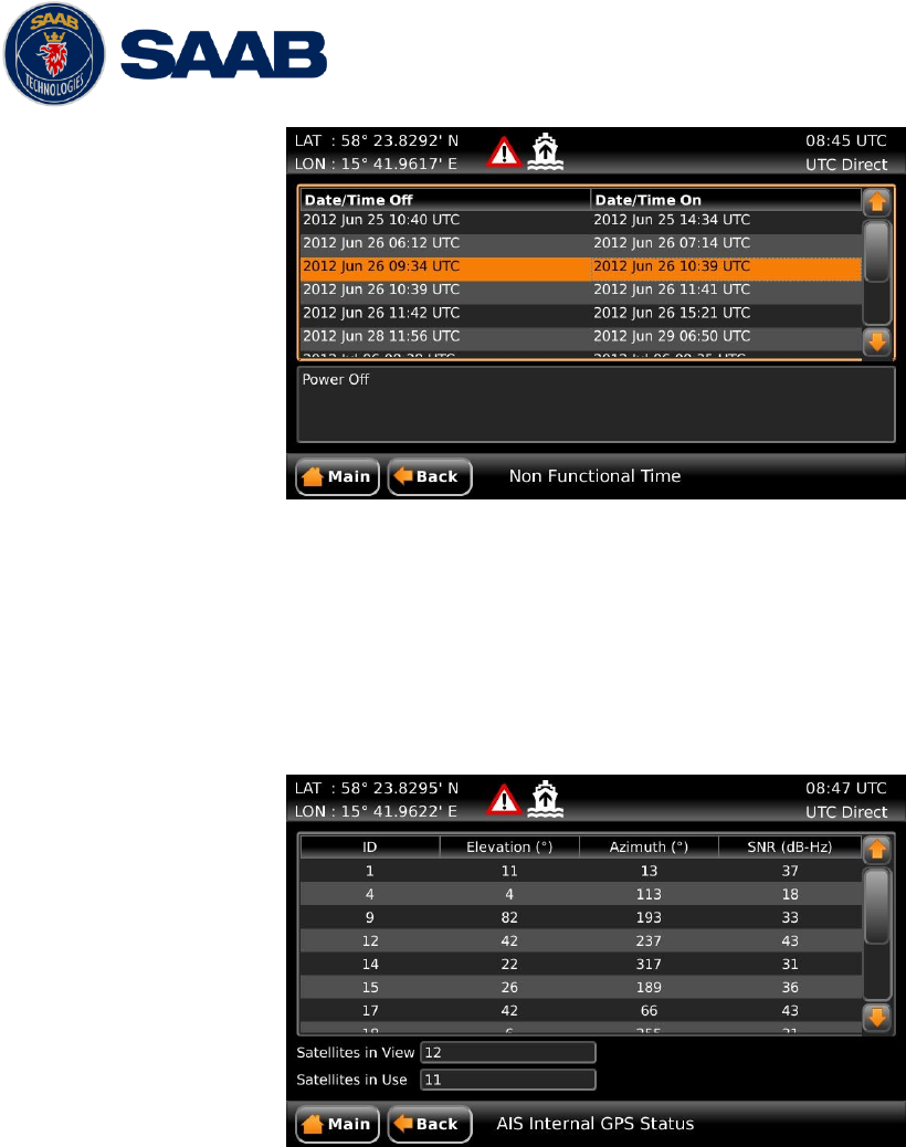
R5 SUPREME AIS System
OPERATION
7000 118-300, B1 Page 60
Figure 29 - Non Functional Time
5.19 AIS Internal GPS Status
This view displays the satellites received by the R5 SUPREME Transponder internal GPS
receiver. The list is sorted by the satellites ID (PRN number) and shows elevation, azimuth and
signal to noise ratio (SNR) for each satellite. The view also displays the total number of satellites
in view and the total number of satellites used in the position calculation reported by GGA
sentence.
Figure 30 – AIS Internal GPS Status
5.20 View Raw Data
This view displays the incoming data on the selected serial port. It is also possible to pause the
data on the screen by pressing the “Freeze” button. The View Raw Data view can be a helpful
tool when trouble shooting the system to see what sensor input is actually received on each port.
The view can be accessed from Main Menu Status View Raw Data.
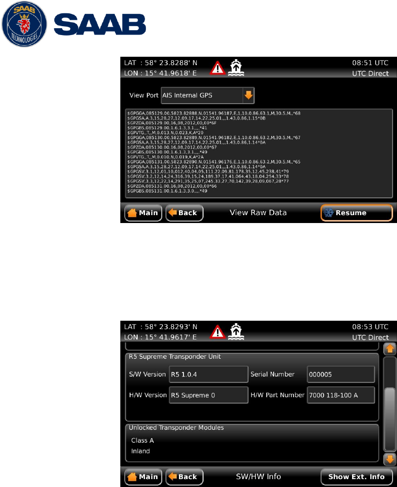
R5 SUPREME AIS System
OPERATION
7000 118-300, B1 Page 61
Figure 31 - View Raw Data
5.21 SW/HW Info
This view displays the software and hardware revisions for the R5 SUPREME AIS System and is
accessed from Main Menu Status SW/HW Info. This information should always be
provided when in contact with Saab TransponderTech support.
Figure 32 - SW/HW Info
5.22 VHF Status
The VHF Status view shows the currently used settings. Channel number, frequency, power and
operation mode are displayed for each VHF transceiver in the R5 SUPREME Transponder. This
information is useful when troubleshooting to make sure that the R5 SUPREME Transponder
uses the expected VHF radio settings. If e.g. a regional area is set and in use, this will affect the
information shown in the VHF Status view.
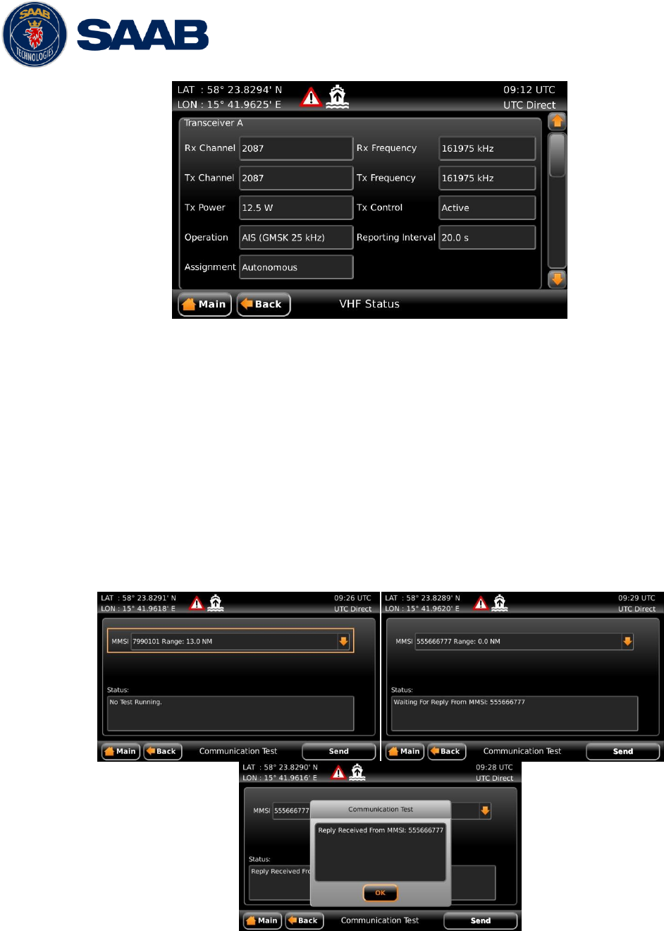
R5 SUPREME AIS System
OPERATION
7000 118-300, B1 Page 62
Figure 33 - VHF Status
5.23 Communication Test
When installing the R5 SUPREME AIS System, or when performing annual testing, a
communication test shall be done to ensure that other transponder systems can receive the R5
SUPREME Transponder’s transmissions. This can be done from the Communication Test view
accessed from Main Menu Maintenance Communication Test.
When entering the Communication Test view a suggested target with a suitable range (between
15 NM and 25 NM) will be selected in the MMSI parameter field if such a target has been
received by the R5 SUPREME AIS System. It is however possible to select a different target for
the communication test. To start the test, click on the “Send” button in lower right corner. A popup
with the result of the communication test will appear if a reply is received or if no reply has been
received within 15 seconds.
Figure 34 - Communication Test
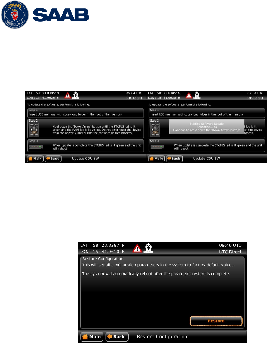
R5 SUPREME AIS System
OPERATION
7000 118-300, B1 Page 63
5.24 Update Software
The software of the R5 SUPREME CDU is easy upgradable via the USB Host interface located
behind the front hatch of the R5 SUPREME CDU. To perform a software update, follow the
instructions in the Update Software view which can be accessed from Main Menu
Maintenance System Update Update CDU SW. For more information about the upgrade
procedure, refer to chapter 6, “Software Upgrade.”
Figure 35 - Update Software
5.25 Factory reset
All config parameters described in section 4.3 “Configuration Parameters” can be set to default
values from the Restore Config view which can be accessed from Main Menu Maintenance
Factory reset.
NOTE: The MMSI parameter will also be reset to zero and therefore the transponder will
stop transmitting and the alarm “Tx Malfunction” will become active.
Figure 36 – Restore Config

R5 SUPREME AIS System
SOFTWARE UPGRADE
7000 118-300, B1 Page 64
6 SOFTWARE UPGRADE
Note: After updating the software add a sticker stating the new software version close to the
product label.
After replacing the CDU or Transponder unit with a new unit, it may be necessary to make a
software upgrade to make sure there are no software compatibility issues.
It is possible to upgrade the software in the Transponder unit and the CDU unit. Make sure to
carefully read the release notes for the software upgrade package first.
The Transponder can be upgraded over Ethernet via the R5 CDU USB port or from the R5 AIS
Junction box USB port.
6.1 Upgrade Software in R5 SUPREME Transponder via Junction Box.
The R5 SUPREME Transponder can be upgraded through the USB host interface located in the
R5 AIS Junction Box. To upgrade the software in the R5 SUPREME Transponder, perform the
following steps:
Unzip the R5 SUPREME Transponder upgrade package in the root folder of an USB memory
stick (must be FAT32 formatted). There should now be a folder called swload in the USB root
folder.
Insert the USB memory stick in the USB host interface in the R5 AIS Junction Box.
Make sure that the R5 SUPREME Transponder’s 26-pin I/O port is connected to the R5
Junction Box.
Hold down the ‘SW-LOAD’-button in the R5 AIS Junction Box. The R5 SUPREME
Transponder will reboot and start the software upgrade. The ‘SW-LOAD’-button must be held
down until the transponder STATUS LED is lit green and the transponder Rx LED is lit
yellow.
6.2 Upgrade Software in R5 SUPREME Transponder via CDU
It is also possible to upgrade the R5 SUPREME Transponder via Ethernet interface by using the
R5 SUPREME CDU. Perform the following steps to initiate the transponder software upgrade
from the R5 SUPREME CDU:
Unzip the R5 SUPREME Transponder upgrade package in the root folder of an USB
memory stick (must be FAT32 formatted). There should now be a folder called swload in
the USB root folder.
Insert the USB memory stick in the USB host interface in the USB port located behind the
front hatch of the R5 SUPREME CDU.
Make sure that the R5 SUPREME CDU and R5 SUPREME Transponder communicates
with each other via Ethernet. Several R5 Transponders may be available on the network.
The currently selected transponder is marked with green colour in the Select Transponder
view which can be accessed from Main Menu Maintenance Configuration
Interface Network Select Transponder.
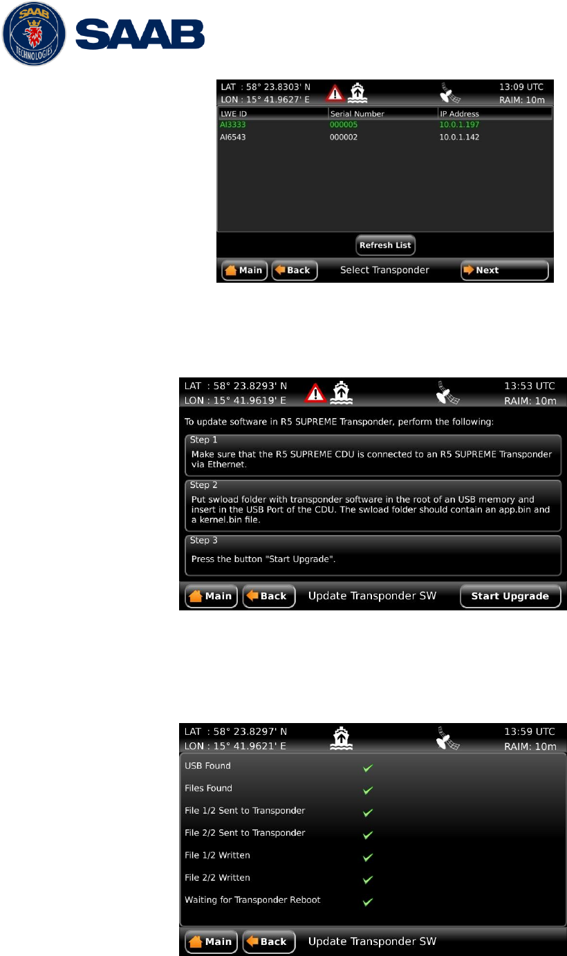
R5 SUPREME AIS System
SOFTWARE UPGRADE
7000 118-300, B1 Page 65
Figure 37 – Select Transponder
Start the upgrade procedure by following the on screen instructions in the Update
Transponder SW view which can be accessed from Main Menu Maintenance
Update Transponder SW.
Figure 38 –Update Transponder SW
The R5 SUPREME Transponder will reboot when the new software has been loaded so
the connection will temporarily be lost. When the transponder has rebooted with the new
software and connection is established again, the following view will be shown, indicating
that the upgrade is complete:
Figure 39 –Update Transponder SW, Complete

R5 SUPREME AIS System
SOFTWARE UPGRADE
7000 118-300, B1 Page 66
6.3 License Upgrade
Some features in the R5 SUPREME AIS System are license controlled and needs to be unlocked
by a special license file. A license file is unique for each single R5 SUPREME Transponder. The
license file name has the following structure;
200001 - 7000 118-611 [Secure W-AIS].lic
In this example:
200001 – The serial number of the R5 SUPREME Transponder unit this key works with.
7000 118-611 – The part number of this license key.
To upgrade the license in the R5 SUPREME AIS System, perform the following:
Place the license file in the root of a FAT32 formatted USB memory. It is possible to put
many license files on the same USB memory if upgrading several units.
Make sure that the R5 SUPREME CDU and R5 SUPREME Transponder communicates
with each other via Ethernet. Several R5 Transponders may be available on the network.
The currently selected transponder is marked with green colour in the Select Transponder
view which can be accessed from Main Menu Maintenance Configuration
Interface Network Select Transponder.
Insert the USB memory in the USB host interface located behind the front hatch of the R5
SUPREME CDU.
Enter the view Main Menu Maintenance System Update License and press the
button “Update License”.
If the license is successfully set, a number of unlocked modules will appear:
Figure 40 –License Upgrade Successful
If a correct license file cannot be found on the USB memory, the following will appear:
Figure 41 – No License File Found
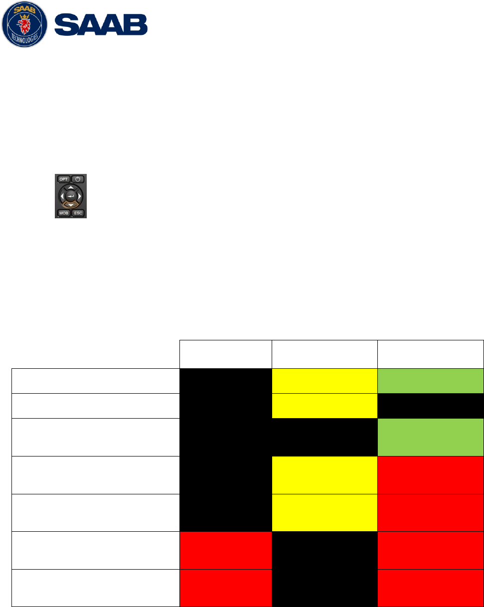
R5 SUPREME AIS System
SOFTWARE UPGRADE
7000 118-300, B1 Page 67
6.4 Upgrade Software in R5 SUPREME CDU
The R5 SUPREME CDU is easy upgradable through the USB host interface located behind the
front hatch. To upgrade the software in the R5 SUPREME CDU, perform the following steps:
Unzip the R5 SUPREME CDU upgrade package in the root folder of an USB memory stick
(must be FAT32 formatted). There should now be a folder called cduswload in the USB root
folder.
Insert the USB memory stick in the USB host interface located behind the front hatch.
Hold down the ‘Down Arrow’-button on the front of the R5 SUPREME CDU and
reboot the system. The ‘Down Arrow’-button must be held down until the
STATUS LED is lit green and the RAIM LED is lit yellow.
The software upgrade is complete when the STATUS LED is lit green. The R5 SUPREME CDU
will automatically reboot after 3 seconds. Check that correct SW has been loaded in the SW/HW
Info view which can be accessed through Main Menu Status SW/HW Info.
If the upgrade process fails, The STATUS LED will be lit red and one of the RAIM LED or MODE
LED starts blinking. Should this happen, hold down the ‘Down Arrow’-button and reboot the R5
SUPREME CDU to try again.
The software upgrade can also be initiated from the Update Software view in the R5 SUPREME
CDU. Refer to chapter 5.24 “Update Software” for more information.
MODE LED
RAIM LED
STATUS
Upgrade mode started
YELLOW
GREEN
Upgrade in progress
Blinking YELLOW
Upgrade complete (automatic
reboot after 3 sec)
GREEN
Error: USB Not Found
Blinking YELLOW
0.5Hz
RED
Error: No SW found on USB
Blinking YELLOW
4Hz
RED
Error: Flash erase failed
Blinking RED
0.5 Hz
RED
Error: Flash write failed
Blinking RED
4 Hz
RED
Table 11 – CDU LED Indicators during Software Upgrade

R5 SUPREME AIS System
TECHNINCAL SPECIFICATIONS
7000 118-300, B1 Page 68
7 TECHNINCAL SPECIFICATIONS
7.1 R5 SUPREME Transponder
7.1.1 Physical
Dimensions:
Height: 77 mm
Width: 227 mm
Depth: 192 mm
Weight:
2.05 kg
7.1.2 Electrical
Input Voltage:
24 VDC
Power Consumption:
20 W (60 W peak)
7.1.3 Environmental
Temperature:
-15˚C to +55˚C (Operational)
-30˚C to +80˚C (Storage)
Vibrations:
IEC 60945 ed. 4
EMC:
IEC 60945 ed. 4
Radio Type Approval:
IEC 61993-2 ed. 1
Compass Safe Distance:
65 cm (for standard magnetic compass)
40 cm (for steering magnetic compass)
7.1.4 VHF Transceiver
Receivers:
156 – 163 MHz (TDMA)
156.525 MHz fixed (DSC, Channel 70)
Transmitter:
156 – 163 MHz
Channel bandwidth:
25 kHz
Output Power:
High: 12,5 W
Low: 1W
“Tanker 1W Mode”: 1W
VHF antenna connector:
BNC-Female
Antenna Input Impedance:
50 ohm

R5 SUPREME AIS System
TECHNINCAL SPECIFICATIONS
7000 118-300, B1 Page 69
7.1.5 Internal GPS Receiver
Type:
GPS L1, C/A Code, 50 Channels
Update rate:
2 Hz
Accuracy:
< 2.5 m (GPS, CEP, 50%, 24 hours static)
< 2.0 m (SBAS, CEP, 50% 24 hours static)
Antenna feeding:
5 VDC
GPS Antenna connector:
TNC-Female
Antenna Input Impedance:
50 ohm
7.1.6 AIS Alarm Relay
Max switching current:
0,1 – 5 A
Max switching voltage:
30 VDC
Max switching power:
150 W
7.2 R5 SUPREME CDU
7.2.1 Physical
Dimensions:
Height: 140 mm
Width: 255 mm
Depth: 84 mm
Weight:
1.6 kg
Dimensions
(incl. gimbal mount)
Height: 170 mm
Width: 295 mm
Depth: 84 mm
Weight
(incl. gimbal mount):
1.75 kg
7.2.2 Electrical
Input Voltage:
12-24 VDC
Power Consumption:
13 W
7.2.3 Environmental
Temperature:
-15˚C to +55˚C (Operational)

R5 SUPREME AIS System
TECHNINCAL SPECIFICATIONS
7000 118-300, B1 Page 70
-30˚C to +80˚C (Storage)
Vibrations and EMC:
IEC 60945 ed. 4
Compass Safe Distance:
75 cm (for standard magnetic compass)
50 cm (for steering magnetic compass)
7.1 R5 AIS Junction Box
7.1.1 Physical
Dimensions:
Height: 72 mm
Width: 273 mm
Depth: 149 mm
Weight:
0.75 kg
7.1.2 Electrical
Input Voltage:
24 VDC
Power Consumption:
13 W
7.1.3 Environmental
Temperature:
-15˚C to +55˚C (Operational)
-30˚C to +80˚C (Storage)
Vibrations and EMC:
IEC 60945 ed. 4
Compass Safe Distance:
75 cm (for standard magnetic compass)
50 cm (for steering magnetic compass)

R5 SUPREME AIS System
TROUBLESHOOTING
7000 118-300, B1 Page 71
8 TROUBLESHOOTING
One of the basic ideas with troubleshooting is to solve a supposed problem on site instead of
immediately sending the suspected part for a costly repair. Solving a supposed problem would in
this aspect mean both to rectify the real problem, but it could also mean that the suspected part is
confirmed to be working or not-working.
Historically, many of the parts sent to Saab TransponderTech for repair have in fact been confirmed
working instead. Another common scenario is that the equipment has faulty I/O settings or other
erroneous configurations, easy to fix on site. A proper troubleshooting would ideally prevent those
unnecessary returns of fully functional equipment.
There are numerous ways to troubleshoot a transponder installation, much dependant on the skill
and experience level of the troubleshooter. The preferred approach may probably also differ
between different individuals, and there is no such thing as right or wrong.
This chapter is not intended to be a step by step troubleshooting instruction, but instead offer a
toolbox with some different techniques on how to troubleshoot the R5 SUPREME AIS System.
8.1 Troubleshooting Prerequisites
A transponders operating environment may naturally differ widely, ranging from small high-speed
RIB’s to very large SOLAS tankers, military aircraft carriers and even submarines. The diversity
of installation environments will of course have impact on the complexity of the troubleshooting,
but it is always advisable to start with minimizing all possible interference sources in order to
simplify the troubleshooting.
Disconnect other NMEA equipment from the R5 (ECDIS, RADAR, NAV, etc.)
Switch off other emission sources (RADAR, SATCOM, VHF, etc.)
We strongly encourage to always use the latest software available for the R5 SUPREME System.
It may contain bug-fixes and other improvements solving already known issues. Always check
existing release notes to see if your problem is to be found.
8.2 Troubleshooting with the Front Panel LED’s of the Transponder
It is very fast and effective to use the LED’s to verify the status of the R5 SUPREME
Transponder. This should always be the first step in the troubleshooting.
8.2.1 STATUS LED (multi-colored)
- The STATUS LED is constantly lit green when the transponder is operating and no
alarms are active.
- The STATUS LED is constantly lit red if there are one or more acknowledged active
alarms in the transponder, but no unacknowledged alarms. Refer to chapter 8.3 for
interpretation of the alarms.
- The STATUS LED is flashing red if there are one or more unacknowledged alarms in
the transponder. Refer to chapter 8.3 for interpretation of the alarms.
If neither color are lit, nor flashing, then check the power supply and make sure that:
The voltage is correct and stable
The polarity is correct and not switched
The available current is sufficient for start up and transmission
The external fuse is functional

R5 SUPREME AIS System
TROUBLESHOOTING
7000 118-300, B1 Page 72
The power cable is undamaged
The power connector is properly connected and secured
8.2.2 RX LED (yellow)
The RX LED is flashing yellow when the transponder is receiving a message from the VDL.
This can be intermittently.
If there is verified traffic on the VDL and the RX LED still is dark, then check the alarm list for
any active alarms. Refer to chapter 8.3 for interpretation of the alarms.
Lack of reception may be an indication of a VHF antenna problem or connectivity issues.
Check the installation for problems.
8.2.3 TX LED (red)
The TX LED is flashing red when the transponder is transmitting a message to the VDL. The
transmission interval is between 2 – 360 seconds. Refer to chapter 8.5.
If the TX LED is completely dark, then check so that the transmission is not switched off either
through an active regional area or by the Tx Mode parameter. It is possible to check the status
on each transceiver in the VHF Status view described in section 5.22.
If the transmission is activated and there still is no red flashing, then check the alarm list for
any active alarms. Refer to chapter 8.3 for interpretation of the alarms.
8.3 Troubleshooting with Alarm Messages
The R5 SUPREME AIS System constantly monitors itself for failures, abnormal conditions and
other important parameters. Some of the monitoring trigger alarms and those alarms are
excellent aids in the troubleshooting process.
An active alarm can have two states, unacknowledged or acknowledged. The state of an alarm
will affect the STATUS LED on both the R5 SUPREME Transponder and the R5 SUPREME
CDU. Refer to chapter 8.2.1.
A new alarm (unacknowledged) will raise a pop-up window that needs to be acknowledged by the
user. The active alarms can be found in the alarm view. Refer to chapter 5.16.
All active alarms are outputted on all the serial interface ports of the R5 SUPREME Transponder
every 30 seconds. The alarm status can for example be used in interfacing ECDIS systems or
centralized alarm systems. The alarms can also be monitored or recorded for troubleshooting
purposes by for example a terminal application.
The status of an alarm can be identified by two letters in the alarm sentence, “A” and “V”. The
alarm sentence is constructed as: $AIALR,hhmmss.ss,xxx,A,A,c-c, where:
hhmmss.ss = Time (UTC) of alarm condition change
xxx = Unique alarm identifier
A = Alarm condition (A = Active, V = Inactive)
A = Alarm’s acknowledge state, A = acknowledged, V = unacknowledged
c-c = Alarm’s description text
$AIALR,hhmmss.ss,xxx,V,A,c-c: Tx malfunction: Alarm is Inactive
$AIALR,hhmmss.ss,xxx,V,V,c-c: Tx malfunction: Alarm is Inactive
$AIALR,hhmmss.ss,xxx,A,A,c-c: Tx malfunction: Alarm is Active and Acknowledged
$AIALR,hhmmss.ss,xxx,A,V,c-c: Tx malfunction: Alarm is Active and Unacknowledged
The alarms that can occur in the R5 SUPREME AIS System are listed below:

R5 SUPREME AIS System
TROUBLESHOOTING
7000 118-300, B1 Page 73
8.3.1 AIS: Tx Malfunction (ID 001)
A Tx Malfunction alarm is generated if there is a malfunction in the radio transmitter hardware
or if the antenna VSWR exceeds an allowed ratio. If the radio transmitter returns to normal
operation or if VSWR returns to a value below the allowed threshold, the alarm is cleared. The
Tx Malfunction alarm is also generated when the MMSI is configured to “0”, in which case the
R5 SUPREME Transponder will not transmit.
8.3.2 AIS: Antenna VSWR Exceeds limit (ID 002)
The VSWR (Voltage Standing Wave Ratio) of the antenna is checked for every transmission
and if it exceeds a given ratio then a VSWR alarm is generated. If the VSWR goes below the
allowed threshold, the alarm is cleared.
8.3.3 AIS: Rx Ch A Malfunction (ID 003)
8.3.4 AIS: Rx Ch B Malfunction (ID 004)
8.3.5 AIS: Rx Ch C Malfunction (ID 005)
The radio receivers are continuously monitored and if any part of the receivers’ hardware
should malfunction, an Rx Malfunction alarm is generated for that receiver. If the radio receiver
returns to normal operation, the alarm is cleared.
8.3.6 AIS: General Failure (ID 006)
This alarm is generated if the R5 SUPREME Transponder fails to initiate the radio or if a
severe hardware failure has occurred. If this alarm occurs, contact your retailer.
8.3.7 AIS: UTC Sync Invalid (ID 007)
This alarm is generated when the R5 SUPREME Transponder loses UTC direct
synchronization (cannot synchronize from internal GPS receiver).
8.3.8 AIS: MKD connection lost (ID 008)
This alarm is active if the R5 SUPREME Transponder has lost connection with the R5
SUPREME CDU. If this alarm occurs, check the Ethernet connection and the network settings.
8.3.9 AIS: Internal/External GNSS position mismatch (ID 009)
This alarm is generated if the difference between the internal and external GNSS position is
more than 100 m for more than 15 minutes.
8.3.10 AIS: NavStatus incorrect (ID 010)
This alarm is generated if the navigational status is incorrect. If e.g. the navigational status is
set to “At Anchor” but the ship is moving faster than 3 knots, the NavStatus incorrect alarm will
become active.
A popup will appear when the "Incorrect NavStatus" alarm is acknowledged to prompt user to
change the navStatus
8.3.11 AIS: Heading sensor offset (ID 011)
This alarm is active when SOG (Speed Over Ground) is greater than 5 kn and the difference
between COG (Course Over Ground) and HDT (True Heading) is greater than 45˚ for 5 min.
8.3.12 AIS: Active AIS SART (ID 014)
This alarm is generated when the R5 SUPREME Transponder has received an active AIS
SART position report.

R5 SUPREME AIS System
TROUBLESHOOTING
7000 118-300, B1 Page 74
8.3.13 AIS: External EPFS Lost (ID 025)
This alarm is generated if the position from the external Electronic Position Fixing System is
invalid (i.e. no external GNSS). Due to the fallback arrangement for the positioning sensor this
alarm can be inactive up to 30 seconds (during which the internal GNSS is used) before the
alarm is activated.
8.3.14 AIS: No Sensor Position In Use (ID 026)
This alarm is active if the R5 SUPREME Transponder does not have a valid position
(latitude/longitude) from any sensor.
8.3.15 AIS: No Valid SOG Information (ID 029) / No Valid COG Information (ID
030)
These alarms are active if the R5 SUPREME Transponder does not have a valid SOG (Speed
Over Ground) or a valid COG (Course Over Ground) from any sensor. The SOG and COG is
based on the speed log (if external GNSS is used and a valid heading is available) or the
GNSS currently in use.
8.3.16 AIS: Heading Lost/Invalid (ID 032)
This alarm is generated if either the heading information is lost/invalid (from external sensors)
or if the heading is undefined.
8.3.17 AIS: No Valid ROT Information (ID 035)
This alarm is active if ROT (Rate Of Turn) is undefined or if no valid ROT information is
available from external sensor or internal calculations.
8.3.18 AIS: CDU Lost Connection To Transponder
This alarm is active if the R5 SUPREME CDU has lost connection with the R5 SUPREME
Transponder. If this alarm occurs, check the Ethernet connection and the network settings.
8.4 Troubleshooting via the CDU
There is a lot of information and data accessible via the CDU that can be useful for
troubleshooting, and that can help finding a presumed problem. The following items are just a few
examples of what to look at.
8.4.1 Transmitted Own Ship Data View
When the transponder transmits data on the VDL, it also simultaneously outputs this data on
all the serial ports. This information is displayed in the Own Ship Data view.
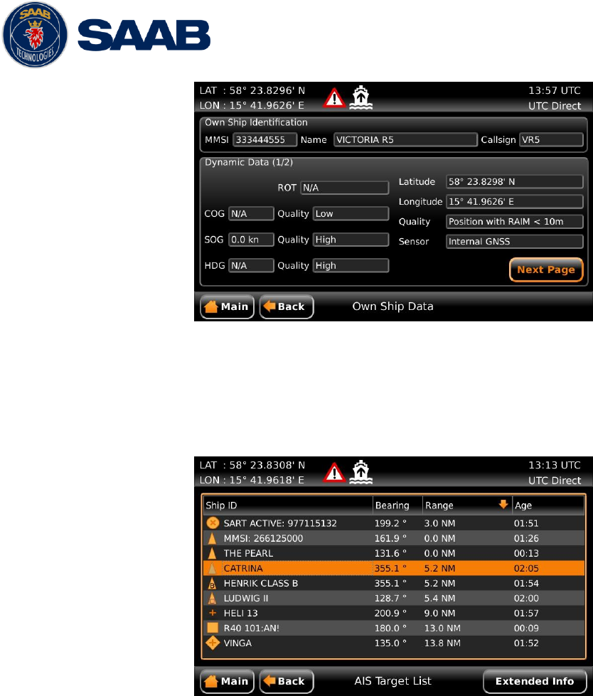
R5 SUPREME AIS System
TROUBLESHOOTING
7000 118-300, B1 Page 75
Figure 42 – Transmitted Own Ship Data
8.4.2 Target List
The target list is primarily useful when analyzing the receiving functionality. The propagation
characteristics of VHF radio frequencies are close to line of sight. A harsh radio environment,
reflections in cables, connectors or the antenna will shorten the effective range.
Figure 43 – Target List
8.4.3 Time in Status Bar
The time (UTC or LOC) in the upper right corner of the display is provided by the transponder.
If the time is not correct, the transponders internal GPS does not have a position fix. This will
also be indicated by the alarm “UTC sync invalid”. This problem is normally caused by a GPS-
antenna failure or damaged antenna cables. This problem may also be caused by interference
from radio equipment on-board.
8.4.4 View Raw Data
The View Raw Data view can be used to see received data on the ports of the R5 SUPREME
AIS System. It is useful for troubleshooting to make sure that connected sensors provide
correct data to the system. The “View Port” parameter determines from which port the data
displayed in the view are taken. It is possible to pause the view by pressing the “Freeze”
button. All data that is received while the view is paused will not be displayed in the view.
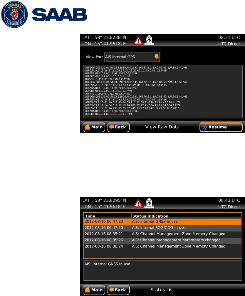
R5 SUPREME AIS System
TROUBLESHOOTING
7000 118-300, B1 Page 76
Figure 44 – View Raw Data
8.4.5 Status List
The status list view is used to display status indications that are stored in the transponder. The
indications are created when an important event has occurred in the transponder. Time of
occurrence and status indication text are shown in the view. A list of all possible indications
can be found in section 8.8 “Indication Messages”.
Figure 45 – Status List
8.5 Reporting Intervals for Class A Transponders
The different information types sent by the R5 SUPREME AIS System are valid for different time
periods and therefore they need different update intervals. These update intervals are defined in
the AIS standard (ITU-R M 1371-4) and should be applied by all transponders. There are
however some exceptions from this, which can be found in the standard. Class B transponders
have for example different intervals than the Class A transponder.
All this needs to be taken in consideration while troubleshooting thus it affects the anticipated
behaviour of a transponder.
R5 SUPREME AIS System
TROUBLESHOOTING
7000 118-300, B1 Page 77
Information type / Condition
Nominal reporting interval
Static Information
6 min, on amendment, on request
Voyage related information
6 min, on amendment, on request
Dynamic information (See conditions below)
- Ship at anchor or moored and not moving faster than 3 knots
3 minutes
- Ship at anchor or moored and moving faster than 3 knots
10 seconds
- Ship 0-14 knots
10 seconds
- Ship 0-14 knots and changing course
3 1/3 seconds
- Ship 14-23 knots
6 seconds
- Ship 14-23 knots and changing course
2 seconds
- Ship > 23 knots
2 seconds
- Ship > 23 knots and changing course
2 seconds
Table 12 – Reporting Intervals
8.6 F.A.Q
8.6.1 I cannot see the vessel on the Internet AIS service
Websites providing AIS services like e.g. www.marinetraffic.com does not cover all the seas of
the world, but only specific coastal areas where AIS receivers have been installed and that
upload the data to the websites. The vessel must be in reception range of these AIS receivers
to show up on the Internet AIS service.
8.6.2 I can “see” the other vessel, but they do not “see” my vessel
There are several reasons why this might happen. The first thing to check is if the R5
SUPREME Transponder is transmitting at all or if is transmitting in low power mode. In VHF
Status view described in section 5.22 it is possible to check the status on all R5 SUPREME
Transponder’s VHF transceivers. Make sure that correct channels and power mode are used.
There might be a regional area set in the transponder that changes the operating mode of the
R5 SUPREME Transponder. Regional areas are listed in the Regional Area view (see section
5.15).
The MMSI must also be configured in order for the R5 SURPEME Transponder to transmit. If
the MMSI is zero, the R5 SUPREME Transponder will be silent.
Another possibility is that the other vessels’ transponder requires a shorter reception range in
order to receive the R5 SUPREME Transponder’s transmissions. In the Target List view and
the Plot view it is possible to see the range and bearing to other vessels.

R5 SUPREME AIS System
TROUBLESHOOTING
7000 118-300, B1 Page 78
8.6.3 The VHF range seems to be short
As a rule of thumb, the VHF range is equal to line of sight from the antenna position, which
means that the higher the antenna is installed, the longer the range will be. It is also important
to follow the guide lines for an antenna installation as thoroughly as possible. Section 3.10
“Mount the VHF Antenna” describes how to best install the VHF antenna.
8.6.4 I can only receive a few GPS satellites
The position of the GPS antenna is of high importance to optimize the GPS reception. Follow
the guide lines of GPS antenna installation described in chapter 3.11 “Mount the GPS
Antenna” as thoroughly as possible.
If the ship is close to a harbour or shore with high structures or travelling in an area with high
terrain, the GPS reception might be worse. The GPS antenna must be installed where it has a
clear view of the sky. The objective is to see the horizon freely through 360 degrees with a
vertical observation of 5 to 90 degrees above the horizon.
The GPS antenna cable should also be as short as possible and with 50 Ω impedance. A very
long antenna cable or faulty impedance can heavily reduce the GPS reception.
8.7 Contacting Support
The primary source for support and RMA issues should for end customers be the dealer where
the equipment was purchased in the first place. Another option is to contact one of our OEM
partners or affiliate service stations and request help. An updated list with our dealers, OEM
partners and service stations can be found at our website, listed under the corresponding
product. www.saabgroup.com/transpondertech.
It is also possible to contact Saab TransponderTech’s technical support if this is preferred.
We recommend contacting us via email at support.transpondetech@saabgroup.com for most
accurate and detailed help. If the situation is very urgent then it is of course also possible to call
us at normal Swedish workdays and working hours. Telephone +46-13-189420.
Before contacting support, always check the following information and include it in the first email,
or have it ready at the phone call:
- All the information provided by the SW/HW Info view which can be accessed from Main
MenuStatusSW/HW Info.
- Detailed fault description
8.8 Indication Messages
The indication messages, with identity and type information, are listed below:
ID Type Message text
021 Status External DGNSS in use
022 Status External GNSS in use
023 Status Internal DGNSS in use (beacon)
024 Status Internal DGNSS in use (msg 17)
025 Status Internal GNSS in use
027 Status External SOG/COG in use
028 Status Internal SOG/COG in use
031 Status Heading valid

R5 SUPREME AIS System
TROUBLESHOOTING
7000 118-300, B1 Page 79
033 Status Rate of Turn Indicator in use
034 Status Other ROT source in use
036 Event Channel management parameters changed
056 Event Channel management zone memory changed
061 Status Enter semaphore mode
062 Event Leave semaphore mode
063 Event NVM Checksum errors
064 Event RATDMA overflow
066 Status Tanker Low VHF Power Mode
067 Status Beacon correction received
068 Status VDL correction received
069 Status No correction received
8.9 Long Range Definitions
A = Ship’s name, call sign, and IMO number
B = Date and time of message composition
C = Position
E = Course over ground (COG)
F = Speed over ground (SOG)
I = Destination and Estimated Time of Arrival (ETA)
O = Draught
P = Ship/Cargo
U = Ship’s length, breadth, type
W= Persons on board
R5 SUPREME AIS System
INTERPRETATION OF INPUT SENTENCES
7000 118-300, B1 Page 80
9 INTERPRETATION OF INPUT SENTENCES
All interface ports accepts the full set of input listed below sentences, except the sentences listed
in section 9.4.1 that are unique to the Long Range interface port.
The protocol of the serial input sentences shall be compliant to IEC 61162-1Ed.4 (2010-11) for
maximum interoperability.
9.1 GPS and Sensor Input Sentences
9.1.1 DTM - Datum Reference
If local code is other than WGS84, then the positions report from that port is
discarded.
$--DTM,ccc,a,x.x,a,x.x,a,x.x,ccc
Field
Format
Name
Comment
1
--DTM
Sentence Id
Used
2
ccc
Local Datum Code
Interpret if it’s WGS84 or not
3
A
Local Datum Subdivision Code
Ignored
4
x.x
Lat Offset (2 fields)
Ignored
Ignored
5
a
6
x.x
Long Offset (2 fields)
Ignored
Ignored
7
a
8
x.x
Altitude Offset
Ignored
9
ccc
Reference Datum Code
Ignored
9.1.2 GBS - GNSS Satellite Fault Detection
If this sentence is received once a second from the position source in use, the
RAIM flag will be set to TRUE.
$--GBS,hhmmss.ss,x.x,x.x,x.x,xx,x.x,x.x,x.x
Field
Format
Name
Comment
1
--GBS
Sentence Id
Used
2
hhmmss.
ss
UTC Time of GGA or GNS
Ignored
3
x.x
Expected Error in latitude
Used
4
x.x
Expected Error in longitude
Used
5
x.x
Expected error in altitude
Ignored
6
xx
ID number of most likely
failed satellite
Ignored
7
x.x
Probability of missed
detection
Ignored
8
x.x
Estimate of bias in meters
Ignored
9
x.x
Standard Deviation of bias
estimate
Ignored
9.1.3 GGA - Global Positioning System Fix Data
$--GGA,hhmmss.ss,llll.ll,a,yyyy.yy,a,x,xx,x.x,x.x,M,x.x,M,x.x,xxxx
Field
Format
Name
Comment
1
--GGA
Sentence Id
Used
2
hhmmss.
ss
UTC of position
UTC Second is used to indicate
Time Stamp
3
llll.ll
Latitude
Used
4
a
5
yyyy.yy
Longitude
Used
6
a
7
x
GPS quality indicator
Used,
1 -> Position with Low Accuracy
2 -> Position with High
R5 SUPREME AIS System
INTERPRETATION OF INPUT SENTENCES
7000 118-300, B1 Page 81
Accuracy
3 -> Position with Low Accuracy
6 -> Dead Reckoning with Low
Accuracy
7 -> Manual mode with low
accuracy
OTHER -> No Position
Used when the GPS is the
internal GPS (Used in
proprietary sentences)
8
xx
Satellites in use
Ignored
9
x.x
Horizontal dilution of
precision
Ignored
10
x.x
Antenna altitude
Ignored
11
M
Units of antenna altitude,
meter
Ignored
12
x.x
Geodial separation
Ignored
13
M
Units of geodial sep.
Ignored
14
x.x
Age of differential GPS data
Ignored
15
xxxx
Differential reference
station ID
Ignored
9.1.4 GLL – Geographic position, latitude/longitude
$--GLL,llll.ll,a,yyyy.yy,a,hhmmss.ss,A,a
Field
Format
Name
Comment
1
--GLL
Sentence Id
Used
2
llll.ll
Latitude
Used
3
a
4
yyyy.yy
Longitude
Used
5
a
6
hhmmss.
ss
UTC of position
UTC Second is used to indicate
Time Stamp
7
A
Status
Used
8
a
Mode indicator
NULL -> Message is ignored
A -> Position with Low Accuracy
D -> Position with High
Accuracy
E -> Dead Reckoning Mode with
Low Accuracy
M-> Manual Mode with Low
Accuracy
OTHER -> No Position
9.1.5 GNS – GNSS fix data
If the Mode Indicator is a NULL field, the sentence is ignored.
$--GNS,hhmmss.ss,llll.ll,a,yyyy.yy,a,c--c,xx,x.x,x.x,x.x,x.x,x.x
Field
Format
Name
Comment
1
--GLL
Sentence Id
Used
2
hhmmss.
ss
UTC of position
UTC Second is used to indicate
Time Stamp
3
llll.ll
Latitude
Used
4
a
5
yyyy.yy
Longitude
Used
6
a
7
c--c
Mode indicator
A, P -> Position with low
accuracy
D, R, F -> Position with high
Accuracy
E -> Dead Reckoning Mode with
Low accuracy
M -> Manual Mode with low
accuracy
OTHER -> No Position
8
xx
Total number of satellites
Used when the GPS source is the
internal GPS (used in
proprietary sentences)
R5 SUPREME AIS System
INTERPRETATION OF INPUT SENTENCES
7000 118-300, B1 Page 82
9
x.x
HDOP
Ignored
10
x.x
Antenna altitude, meter
Ignored
11
x.x
Geodial separation
Ignored
12
x.x
Age of differential
corrections
Ignored
13
x.x
Differential reference
station ID
Ignored
9.1.6 HDT - Heading, True
The use of this sentence is talker identifier dependent.
$--HDT,x.x,T
Field
Format
Name
Comment
1
--HDG
Sentence Id
Used
2
x.x
Heading, degrees true
Used
3
T
NOTE: HDT input must be sent at least every 3 seconds for the
R5 SUPREME to calculate ROT from the HDT input.
9.1.7 OSD – Own ship data
$--OSD,x.x,A,x.x,a,x.x,a,x.x,x.x,a
Field
Format
Name
Comment
1
--OSD
Sentence Id
Used
2
x.x
Heading, degrees true
Used if heading status is ‘A’
3
A
Heading status
Used
4
x.x
Vessel course, degrees true
Used as COG
5
a
Course reference
Used1
6
x.x
Vessel speed
Used as SOG
7
a
Speed reference
Used1
8
x.x
Vessel set
Ignored
9
x.x
Vessel drift
Ignored
10
a
Speed units
Used to convert SOG to knots
9.1.8 RMC – Recommended minimum specific GNSS data
$--RMC,hhmmss.ss,A,llll.ll,a,yyyy.yy,a,x.x,x.x,xxxxxx,x.x,a,a
Field
Format
Name
Comment
1
--RMC
Sentence Id
Used
2
hhmmss.
ss
UTC of position
UTC Second is used to indicate
Time Stamp
3
A
Status
Used
4
llll.ll
Latitude
Used
5
a
6
yyyy.yy
Longitude
Used
7
a
8
x.x
Speed over ground, knots
Used
9
x.x
Course over ground, degrees
true
Used
10
xxxxxx
Date
Ignored
11
x.x
Magnetic variation
Ignored
12
a
13
a
Mode indicator
NULL -> Message is ignored
A -> Position with low accuracy
D -> Position with high
accuracy
E -> Dead Reckoning Mode with
Low accuracy
M -> Manual Mode with low
accuracy
OTHER -> No Position
1
SOG and COG are used if both COG reference and SOG reference are set to either: B, P, R
R5 SUPREME AIS System
INTERPRETATION OF INPUT SENTENCES
7000 118-300, B1 Page 83
9.1.9 ROT – Rate of turn
The rate of turn value is only used if the talker identifier is TI. Otherwise the
value will only be used to determine the direction, i.e. ”Moving Right” or
”Moving Left”.
$--ROT,x.x,A
Field
Format
Name
Comment
1
--ROT
Sentence Id
Used
2
x.x
Rate of turn
Used if Status is set to ‘A’
3
A
Status
Used
9.1.10 VBW - Dual Ground / Water Speed
The current position source must be external GPS, and heading must be
available for the transponder to accept this sentence.
$--VBW,x.x,x.x,A,x.x,x.x,A,x.x,A,x.x,A
Field
Format
Name
Comment
1
--ROT
Sentence Id
Used
2
x.x
Longitudinal water speed
Ignored
3
x.x
Transverse water speed
Ignored
4
A
Status: water speed
Ignored
5
x.x
Longitudinal ground speed
Used if Status is set to A
6
x.x
Transverse ground speed
Used if Status is set to A
7
A
Status: ground speed
Used
8
x.x
Stern transverse water speed
Ignored
9
A
Status stern water speed
Ignored
10
x.x
Stern transverse ground speed
Ignored
11
A
Status stern ground speed
Ignored
9.1.11 VTG – Course over ground and ground speed
$--VTG,x.x,T,x.x,M,x.x,N,x.x,K,a
Field
Format
Name
Comment
1
--VTG
Sentence Id
Used
2
x.x
Course over ground, degrees
true
Used
3
T
4
x.x
Course over ground, degrees
magnetic
Ignored
5
M
6
x.x
Speed over ground, knots
Used
7
N
8
x.x
Speed over ground, km/h
Ignored
9
K
10
a
Mode indicator
Used
9.1.12 ZDA – Time and date
This message is only interpreted if it’s received from the internal GPS (the
time synchronisation source).
$--ZDA,hhmmss.ss,xx,xx,xxxx,xx,xx
Field
Format
Name
Comment
1
--ZDA
Sentence Id
Used
2
hhmmss.
ss
UTC
Used
3
xx
Day (UTC)
Used
4
xx
Month (UTC)
Used
5
xxxx
Year (UTC)
Used
6
xx
Local zone hours
Ignored
7
xx
Local zone minutes
Ignored
R5 SUPREME AIS System
INTERPRETATION OF INPUT SENTENCES
7000 118-300, B1 Page 84
9.2 General Input Sentences
9.2.1 ACK – Acknowledge Alarm
$--ACK,xxx
Field
Format
Name
Comment
1
--ACK
Sentence Id
Used
2
xxx
ID of the alarm source
Used
9.2.2 EPV – Command or report equipment property value
$--EPV,a,c--c,c--c,x.x,c--c,
Field
Format
Name
Comment
1
--EPV
Sentence Id
Used
2
a
Sentence status flag
Used
3
c--c
Destination equipment type
Used, AI or STT
4
c--c
Unique Identifier
Used, may be null
5
x.x
Property identifier
Used
6
c--c
Value of property to be set
Used
9.2.3 SPW – Security Password Sentence
$--SPW,ccc,c--c,x,c--c
Field
Format
Name
Comment
1
--SPW
Sentence Id
Used
2
ccc
Password protected sentece
Used
3
c--c
Unique Identifier
Used, may be NULL
4
x
Password level
Used
5
c--c
Password
Used
9.2.4 HBT – Heartbeat Supervision Sentence
$--HBT,x.x,A,x
Field
Format
Name
Comment
1
--SPW
Sentence Id
Used
2
x.x
Configured repeat interval
Used (Limited to 60 sec)
3
A
Equipment status
Used
4
x
Sequential sentence
identifier
Ignored
9.3 AIS Specific Input Sentences
9.3.1 ABM – Addressed Binary and Safety-Related Message
!--ABM,x,x,x,xxxxxxxxx,x,x.x,s--s,x
Field
Format
Name
Comment
1
--ABM
Sentence Id
Used
2
x
Total nr of sentences
Used if in interval 1..9,
otherwise the sentence is
ignored
3
x
Sentence number
Used if in interval 1..total
sentences, otherwise the
sentence is ignored
4
x
Sequential message identifier
Used if in interval 0..3,
otherwise the sentence is
ignored
5
xxxxxxx
xxx
MMSI of Destination
Used
6
X
AIS Channel
Used
7
x.x
Message Id
Used if 6 or 12, otherwise the
sentence is ignored
8
s--s
Encapsulated Data
Used
9
x
Number of filled bits
Used
R5 SUPREME AIS System
INTERPRETATION OF INPUT SENTENCES
7000 118-300, B1 Page 85
9.3.2 ACA – AIS Regional Channel Assignment Message
The zone created of this sentence must be accepted by the channel
management rules (size of zone, distance to own position, valid channel
number etc). If the zone isn’t accepted, the zone will be ignored.
$--ACA,x,llll.ll,a,yyyy.yy,a,llll.ll,a,yyyy.yy,a,x,xxxx,x,xxxx,x,x,x,a,x,
hhmmss.ss
Field
Format
Name
Comment
1
--ACA
Sentence Id
Used
2
x
Sequence number
Ignored
3
llll.ll
NE latitude (2 fields)
Used
4
a
5
yyyy.yy
NE longitude (2 fields)
Used
6
a
7
llll.ll
SW latitude (2 fields)
Used
8
a
9
yyyy.yy
SW longitude (2 fields)
Used
10
a
11
x
Transitional zone size
Used
12
xxxx
Channel A
Used
13
x
Channel A bandwidth
Used
14
xxxx
Channel B
Used
15
x
Channel B bandwidth
Used
16
x
Tx/Rx mode
Used
17
x
Power level
Used
18
a
Information source
Ignored
19
x
In use flag
Ignored
20
hhmmss.
ss
Time of In use change
Ignored
9.3.3 AIQ – Query Sentence
$--AIQ,ccc
Field
Format
Name
Comment
1
--
Talker ID of requester
Used
2
AIQ
Talker ID for device
Used
3
ccc
Approved sentence formatter
of data being requested
It’s possible to query the
following sentences:
ACA, ALR, EPV, LRI, SSD, TRL,
TXT and VSD
9.3.4 AIR – AIS Interrogation Request
This sentence can also be used to do a “UTC Request”.
$--AIR,xxxxxxxxx,x.x,x,x.x,x,xxxxxxxxx,x.x,x
Field
Format
Name
Comment
1
--AIR
Sentence Id
Used
2
xxxxxxx
xx
MMSI 1
Used
3
x.x
Message ID 1.1
Used
4
x
Message sub section
Ignored
5
x.x
Message ID 1.2
Used, may be NULL
6
x
Message sub section
Ignored
7
xxxxxxx
xx
MMSI 2
Used, may be NULL
8
x.x
Message ID 2.1
Used, may be NULL
9
x
Message sub section
Ignored
10
x
Channel
Used, may be NULL
R5 SUPREME AIS System
INTERPRETATION OF INPUT SENTENCES
7000 118-300, B1 Page 86
9.3.5 BBM – Broadcast Binary Message
$--BBM,x,x,x,x,x.x,s--s,x
Field
Format
Name
Comment
1
--BBM
Sentence Id
Used
2
X
Total number of sentences
Used if in interval 1..9,
otherwise rejected
3
X
Sentence number
Used if in interval 1..total
number of sentences, otherwise
rejected.
4
X
Sequential message identifier
Used if in interval 0..9,
otherwise rejected
5
X
AIS channel
Used
6
x.x
Message Id
Used if 8 or 14
7
s—s
Encapsulated data
Used
8
X
Number of filled bits
Used
9.3.6 SSD – Ship Static Data
$--SSD,c--c,c--c,xxx,xxx,xx,xx,c,aa
Field
Format
Name
Comment
1
--SSD
Sentence Id
Used
2
c--c
Call sign
Used, may be NULL
3
c--c
Name
Used, may be NULL
4
xxx
Pos ref A
Used to change position
reference for the position
source in use. May be NULL.
5
xxx
Pos ref B
Used to change position
reference for the position
source in use. May be NULL.
6
xx
Pos ref C
Used to change position
reference for the position
source in use. May be NULL.
7
xx
Pos ref D
Used to change position
reference for the position
source in use. May be NULL.
8
c
DTE
Ignored
9
aa
Source identifier
Used
9.3.7 VSD – Voyage Static Data
$--VSD,x.x,x.x,x.x,c--c,hhmmss.ss,xx,xx,x.x,x.x
Field
Format
Name
Comment
1
--VSD
Sentence Id
Used
2
x.x
Type of ship and cargo
Used
3
x.x
Maximum present draught
Used
4
x.x
Persons on-board
Used
5
c--c
Destination
Used
6
hhmmss.
ss
Est. UTC of arrival
Used
7
Xx
Est. day of arrival
Used
8
Xx
Est. month of arrival
Used
9
x.x
Navigational status
Used
10
x.x
Regional application flags
Used
9.4 Long Range Input Sentences
9.4.1 On Long Range Port
The LR sentences can only be used with the Long Range interface port.
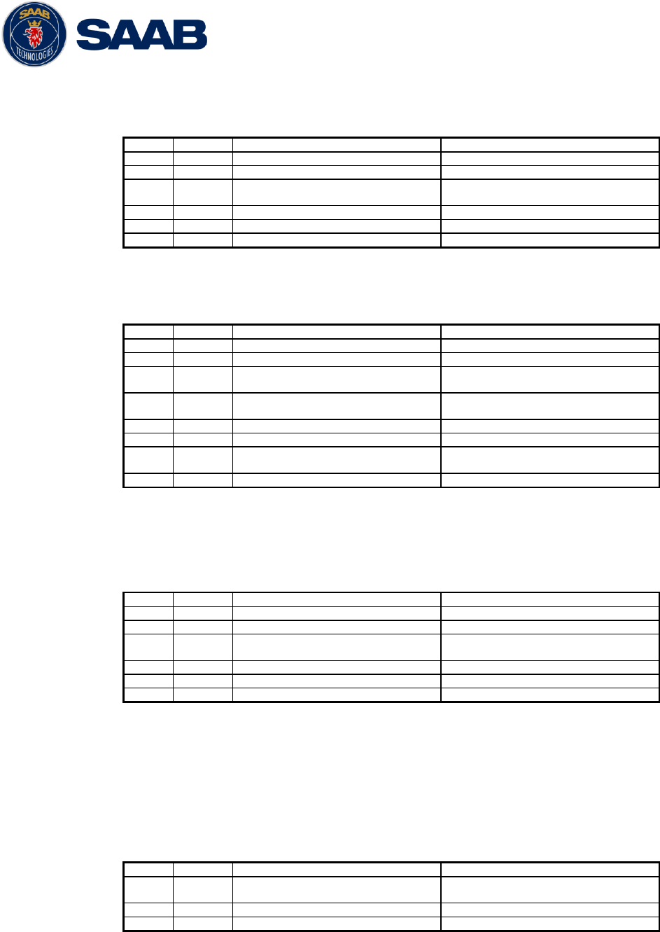
R5 SUPREME AIS System
INTERPRETATION OF INPUT SENTENCES
7000 118-300, B1 Page 87
9.4.1.1 LRF – AIS long-range function
$--LRF,x,xxxxxxxxx,c—c,c—c,c—c
Field
Format
Name
Comment
1
--LRF
Sentence Id
Used
2
x
Sequence number
Used
3
xxxxxxx
xx
MMSI of requestor
Used
4
c--c
Name of requestor
Used
5
c--c
Function request
Used
6
c--c
Function reply status
Used
9.4.1.2 LRI – AIS long-range interrogation
$--LRI,x,a,xxxxxxxxx,xxxxxxxxx,llll.ll,a,yyyyy.yy,a,llll.ll,a,yyyyy.yy,a
Field
Format
Name
Comment
1
--LRI
Sentence Id
Used
2
x
Sequence number
Used
3
xxxxxxx
xx
MMSI of requestor
Used
4
xxxxxxx
x
MMSI of destination
Used
5
llll.ll
Latitude
Used
6
a
N / S
Used
7
yyyyy.y
y
Longitude
Used
8
a
E / W
Used
9.4.2 On Other Input Ports
9.4.2.1 LRF – AIS long-range function
$--LRF,x,xxxxxxxxx,c—c,c—c,c—c
Field
Format
Name
Comment
1
--LRF
Sentence Id
Used
2
x
Sequence number
Used
3
xxxxxxx
xx
MMSI of requestor
Used
4
c--c
Name of requestor
Used
5
c--c
Function request
Used
6
c--c
Function reply status
Used
9.5 Proprietary Input Sentences
All Saab TransponderTech Proprietary Sentences will have talker ID PSTT.
9.5.1 Proprietary Query message PSTT,101
$PSTT,101,c--c,
Field
Format
Name
Comment
1
PSTT
Proprietary SAAB
TranspondeTech Sentence
Used
2
101
Sentence Query
Used
3
c--c
Proprietary sentence to query
Used
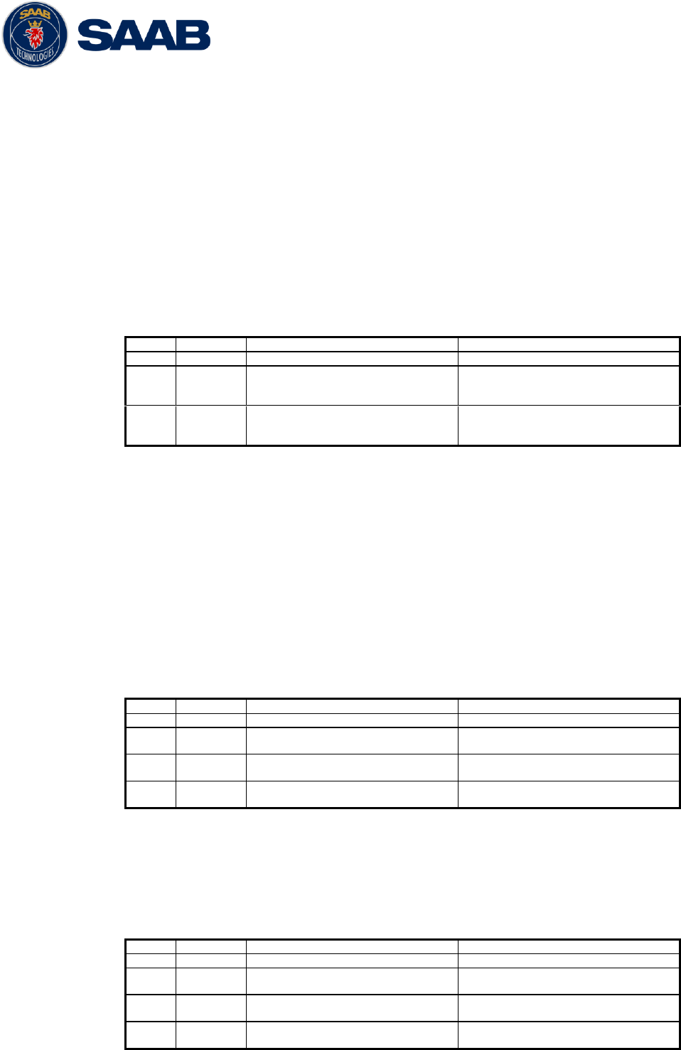
R5 SUPREME AIS System
INTERPRETATION OF OUTPUT SENTENCES
7000 118-300, B1 Page 88
10 INTERPRETATION OF OUTPUT SENTENCES
10.1 Proprietary Output Sentences (PSTT)
In addition to the standardized IEC sentences, the R5 SUPREME System is able to output the
proprietary sentences listed below. All Saab TransponderTech Proprietary Sentences have talker
ID “PSTT”.
10.1.1 $PSTT,10A – UTC Date and Time
This sentence provides UTC Date and Time, i.e. R5 SUPREME system time (based on
internal GNSS time). It is output approximately once every 10 seconds (± 1 s).
$PSTT,10A,YYYYMMDD,HHMMSS
Field
Format
Name
Comment
1
10A
Sentence Id
10A always
2
YYYYMMDD
Date
Year, month and day in decimal
notation.
(00000000 = Not available)
3
HHMMSS
Time
Hour, minute and second in
decimal notation.
(999999 = Not available)
Example: $PSTT,10A,20121028,135230*<FCS><CR><LF>
= Date October 28, 2012
= Time 13:52:30 UTC
10.1.2 $PSTT,10C – Data Link Status
This sentence provides information about the traffic on the VHF data link. It is output
approximately once every 60 seconds. Traffic load is calculated over the last frame (i.e. 60
seconds). Number of units is derived from the internal user list and is generally the number of
received units within the last few minutes.
$PSTT,10C,C,LLL,NNNN
Field
Format
Name
Comment
1
10C
Sentence Id
10C always
2
C
Channel
A = VDL Channel A
B = VDL Channel B
3
LLL
Traffic Load
Data link traffic load in
precent, 0-100.
4
NNNN
Number of Units
Number of units occupying the
data link
10.1.3 $PSTT,146 – System Operational Mode Status
This sentence reports the system operational mode. This sentence is output on change,
periodically every minute and on request using PSTT,101.
$PSTT,146,x,x,x*hh<CR><LF>
Field
Format
Name
Comment
1
146
Sentence Id
146 always
2
X
1 W Mode
0 = Default
1 = 1 Watt
3
X
System Mode
0 = Class A
1 = Inland
4
X
Transmit mode
0 = Normal
1 = Silent
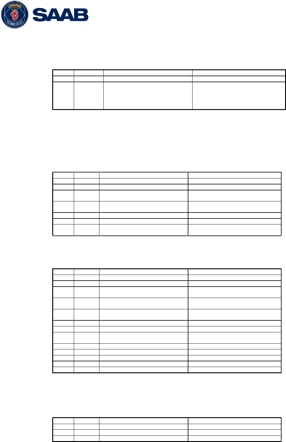
R5 SUPREME AIS System
INTERPRETATION OF OUTPUT SENTENCES
7000 118-300, B1 Page 89
10.1.4 $PSTT,1F3 – Transponder Restart
This sentence will be output when the transponder has restarted.
$PSTT,1F3,R
Field
Format
Name
Comment
1
1F3
Sentence Id
1F3 always
2
R
Restart Reason
0 = Unknown
1 = Cold Start
2 = General Protection Fault
3 = Power Fail
4 = Warm Start
10.2 Long Range Output Sentences
10.2.1 On Long Range Port
10.2.1.1 LR1 – AIS long-range reply sentence 1
$--LR1,x,xxxxxxxxx,xxxxxxxxx,c—c,c—c,xxxxxxxxx
Field
Format
Name
Comment
1
--LR1
Sentence Id
Used
2
x
Sequence number
Used
3
xxxxxxx
xx
MMSI of responder
Used
4
xxxxxxx
xx
MMSI of requestor (reply
destination
Used
5
c--c
Ship’s name
Used
6
c--c
Call sign
Used
7
xxxxxxx
xx
IMO Number
Used
10.2.1.2 LR2 – AIS long-range reply sentence 2
$--LR2,x,xxxxxxxxx,xxxxxxxx,hhmmss.ss,llll.ll,a,yyyyy.yy,a,x.x,T,x.x,N
Field
Format
Name
Comment
1
--LR2
Sentence Id
Used
2
x
Sequence number
Used
3
xxxxxxx
xx
MMSI of responder
Used
4
xxxxxxx
x
Date
Used
5
hhmmss.
ss
UTC time of position
Used
6
llll.ll
Latitude
Used
7
a
N / S
Used
8
yyyyy.y
y
Longitude
Used
9
a
E / W
Used
10
x.x
Course over ground
Used
11
T
Validity of COG
Used
12
x.x
Speed over ground
Used
13
N
Validity of SOG
Used
10.2.1.3 LR3 – AIS long-range reply sentence 3
$--LR3,x,xxxxxxxxx,c—c,xxxxxx,hhmmss.ss,x.x,x.x,x.x,x.x,x.x,x.x
Output rate: On event
Field
Format
Name
Comment
1
--LR3
Sentence Id
Used
2
x
Sequence number
Used
3
xxxxxxx
MMSI of responder
Used
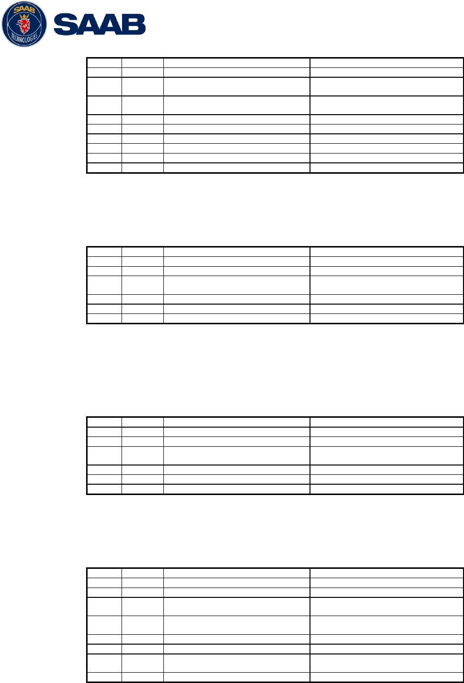
R5 SUPREME AIS System
INTERPRETATION OF OUTPUT SENTENCES
7000 118-300, B1 Page 90
xx
4
c--c
Voyage destination
Used
5
xxxxxxx
x
ETA Date
Used
6
hhmmss.
ss
ETA time
Used
7
x.x
Draught
Used
8
x.x
Ship / Cargo
Used
9
x.x
Ship length
Used
10
x.x
Ship width
Used
11
x.x
Ship type
Used
12
x.x
Persons
Used
10.2.1.4 LRF – AIS long-range function
$--LRF,x,xxxxxxxxx,c—c,c—c,c—c
Output rate: On event
Field
Format
Name
Comment
1
--LRF
Sentence Id
Used
2
x
Sequence number
Used
3
xxxxxxx
xx
MMSI of requestor
Used
4
c--c
Name of requestor
Used
5
c--c
Function request
Used
6
c--c
Function reply status
Used
10.2.2 On All Other Output Ports
10.2.2.1 LRF – AIS long-range function
$--LRF,x,xxxxxxxxx,c—c,c—c,c—c
Output rate: On event
Field
Format
Name
Comment
1
--LRF
Sentence Id
Used
2
x
Sequence number
Used
3
xxxxxxx
xx
MMSI of requestor
Used
4
c--c
Name of requestor
Used
5
c--c
Function request
Used
6
c--c
Function reply status
Used
10.2.2.2 LRI – AIS long-range interrogation
$--LRI,x,a,xxxxxxxxx,xxxxxxxxx,llll.ll,a,yyyyy.yy,a,llll.ll,a,yyyyy.yy,a
Output rate: On event
Field
Format
Name
Comment
1
--LRI
Sentence Id
Used
2
x
Sequence number
Used
3
xxxxxxx
xx
MMSI of requestor
Used
4
xxxxxxx
x
MMSI of destination
Used
5
llll.ll
Latitude
Used
6
a
N / S
Used
7
yyyyy.y
y
Longitude
Used
8
a
E / W
Used
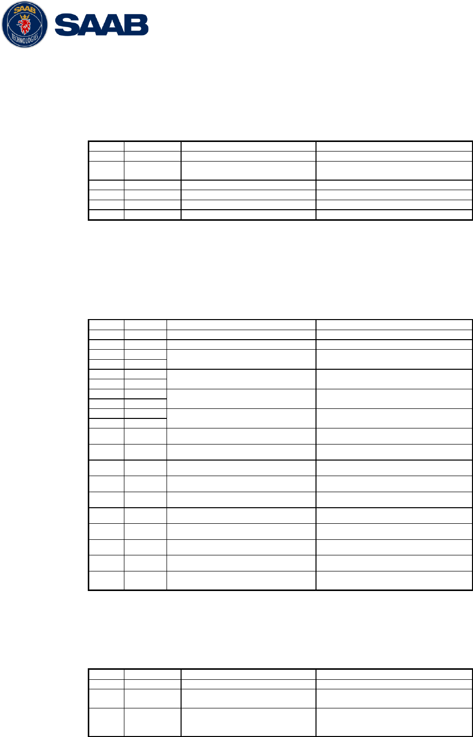
R5 SUPREME AIS System
INTERPRETATION OF OUTPUT SENTENCES
7000 118-300, B1 Page 91
10.3 AIS Output Sentences
10.3.1 ABK – AIS Addressed and binary broadcast acknowledgement
$ -- ABK,xxxxxxxxx,x,x.x,x,x
Output rate: On event.
Field
Format
Name
Comment
1
--ABK
Sentence Id
Used
2
xxxxxxxxx
MMSI of the addressed AIS
unit
Used
3
x
AIS channel of reception
Used
4
x.x
ITU - R M.1371 Message ID
Used
5
x
Message sequence number
Used
6
x
Type of acknowledgement
Used
10.3.2 ACA – AIS Regional Channel Assignment Message
$--ACA,x,llll.ll,a,yyyy.yy,a,llll.ll,a,yyyy.yy,a,x,xxxx,x,xxxx,x,x,x,a,x,
hhmmss.ss
Output rate: On event. On request.
Field
Format
Name
Comment
1
--ACA
Sentence Id
Used
2
x
Sequence number
Ignored
3
llll.ll
NE latitude (2 fields)
Used
4
a
5
yyyy.yy
NE longitude (2 fields)
Used
6
a
7
llll.ll
SW latitude (2 fields)
Used
8
a
9
yyyy.yy
SW longitude (2 fields)
Used
10
a
11
x
Transitional zone size
Used
12
xxxx
Channel A
Used
13
x
Channel A bandwidth
Used
14
xxxx
Channel B
Used
15
x
Channel B bandwidth
Used
16
x
Tx/Rx mode
Used
17
x
Power level
Used
18
a
Information source
Ignored
19
x
In use flag
Ignored
20
hhmmss.
ss
Time of In use change
Ignored
10.3.3 ALR – Set alarm state
$--ALR,hhmmss.ss,xxx,A, A,c--c
Output rate: On event, on request, and automatically. Output every 30s for
active alarms and every 60s when no active alarms.
Field
Format
Name
Comment
1
--ALR
Sentence Id
Used
2
hhmmss.ss
Time of alarm condition
change, UTC
Used
3
Xxx
Unique alarm number
(identifier) at alarm
source
Used
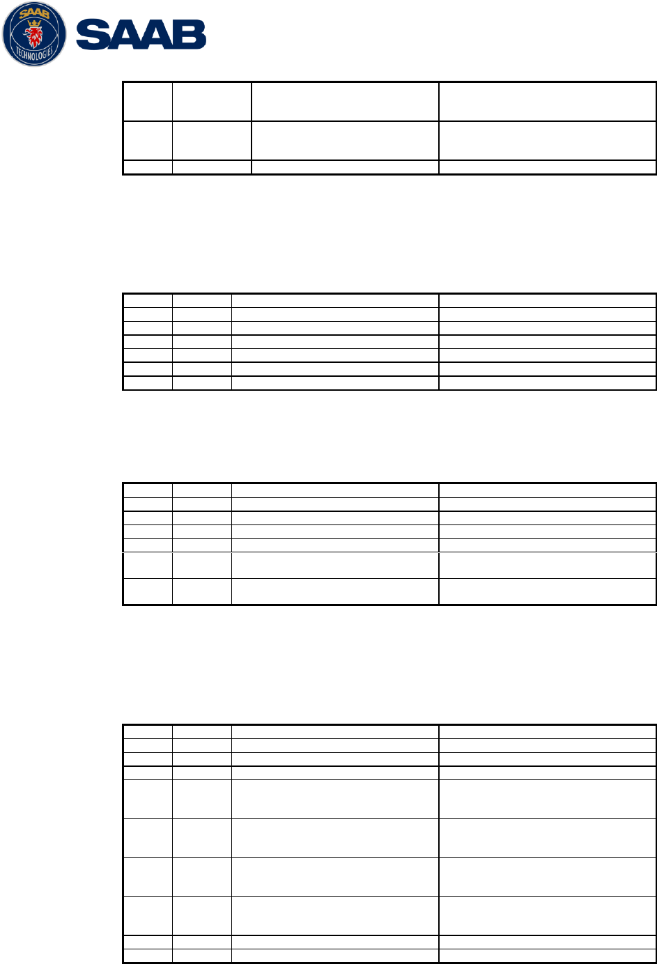
R5 SUPREME AIS System
INTERPRETATION OF OUTPUT SENTENCES
7000 118-300, B1 Page 92
4
A
Alarm condition
A = threshold exceeded
V = not exceeded
Used
5
A
Alarm’s acknowledge state
A = acknowledged
V = unacknowledged
Used
6
c--c
Alarm’s description text
Used
10.3.4 EPV – Command or report equipment property value
$--EPV,a,c--c,c--c,x.x,c—c
Output rate: On request.
Field
Format
Name
Comment
1
--EPV
Sentence Id
Used
2
a
Sentence status flag
Used
3
c--c
Destination equipment type
Used
4
c--c
Unique Identifier
Used
5
x.x
Property identifier
Used
6
c--c
Value of property
Used
10.3.5 NAK – Negative acknowledgement
$--NAK,cc,ccc,c--c,x.x,c—c
Output rate: On event
Field
Format
Name
Comment
1
--NAK
Sentence Id
Used
2
cc
Talker identifier
Used
3
ccc
Affected sentence formatter
Used
4
c--c
Unique Identifier
Used
5
x.x
Reason code for negative
acknowledgement
Used
6
c--c
Negative acknowledgement’s
descriptive text
Used
10.3.6 SSD – Ship Static Data
$--SSD,c--c,c--c,xxx,xxx,xx,xx,c,aa
Output rate: On request.
Field
Format
Name
Comment
1
--SSD
Sentence Id
Used
2
c--c
Call sign
Used, may be NULL
3
c--c
Name
Used, may be NULL
4
xxx
Pos ref A
Used to change position
reference for the position
source in use. May be NULL.
5
xxx
Pos ref B
Used to change position
reference for the position
source in use. May be NULL.
6
xx
Pos ref C
Used to change position
reference for the position
source in use. May be NULL.
7
xx
Pos ref D
Used to change position
reference for the position
source in use. May be NULL.
8
c
DTE
Ignored
9
aa
Source identifier
Ignored
10.3.7 TRL – AIS transmitter non functioning log
$--TRL,x.x,x.x,x,xxxxxxxx,hhmmss.ss,xxxxxxxx,hhmmss.ss,x
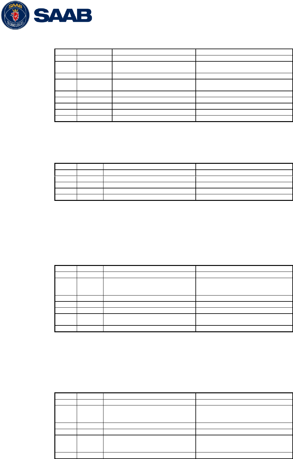
R5 SUPREME AIS System
INTERPRETATION OF OUTPUT SENTENCES
7000 118-300, B1 Page 93
Output rate: On request. Up to 10 sentences in a burst.
Field
Format
Name
Comment
1
--TRL
Sentence Id
Used
2
x.x
Total number of log
entries
Used
3
x.x
Log entry number
Used
4
x
Sequential message
identifier
Used
5
xxxxxxxx
Switch off date
Used
6
hhmmss.ss
Switch off UTC time
Used
7
xxxxxxxx
Switch on date
Used
8
hhmmss.ss
Switch on UTC time
Used
9
X
Reason code1
Used
10.3.8 TXT – Text transmission
$--TXT,xx,xx,xx,c--c
Output rate: On request, on event.
Field
Format
Name
Comment
1
--TXT
Sentence Id
Used
2
xx
Total number of sentences
Used
3
xx
Sentence number
Used
4
xx
Text identifier
Used
5
c--c
Text message
Used
10.3.9 VDM – AIS VHF data-link message
!--VDM,x,x,x,a,s—s,x
Only output on serial port when baudrate is 38400 bps or higher.
Output rate: On VHF message receive event.
Field
Format
Name
Comment
1
--VDM
Sentence Id
Used
2
X
Total number of sentences
needed to transfer the
message
Used
3
X
Sentence number
Used
4
X
Sequential message identifier
Used
5
A
AIS channel
Used
6
s—s
Encapsulated ITU-R M.1371
radio message
Used
7
X
Number of fill bits
Used
10.3.10 VDO – AIS VHF data-link own-vessel report
!--VDO,x,x,x,a,s—s,x
Only output on serial port when baudrate is 38400 bps or higher.
Output rate: On VHF transmission event. “Dummy” messages once per
second.
Field
Format
Name
Comment
1
--VDO
Sentence Id
Used
2
X
Total number of sentences
needed to transfer the
message
Used
3
X
Sentence number
Used
4
X
Sequential message identifier
Used
5
A
AIS channel
Used for transmission event.
Not used for “dummy” position
messages.
6
s—s
Encapsulated ITU-R M.1371
Used
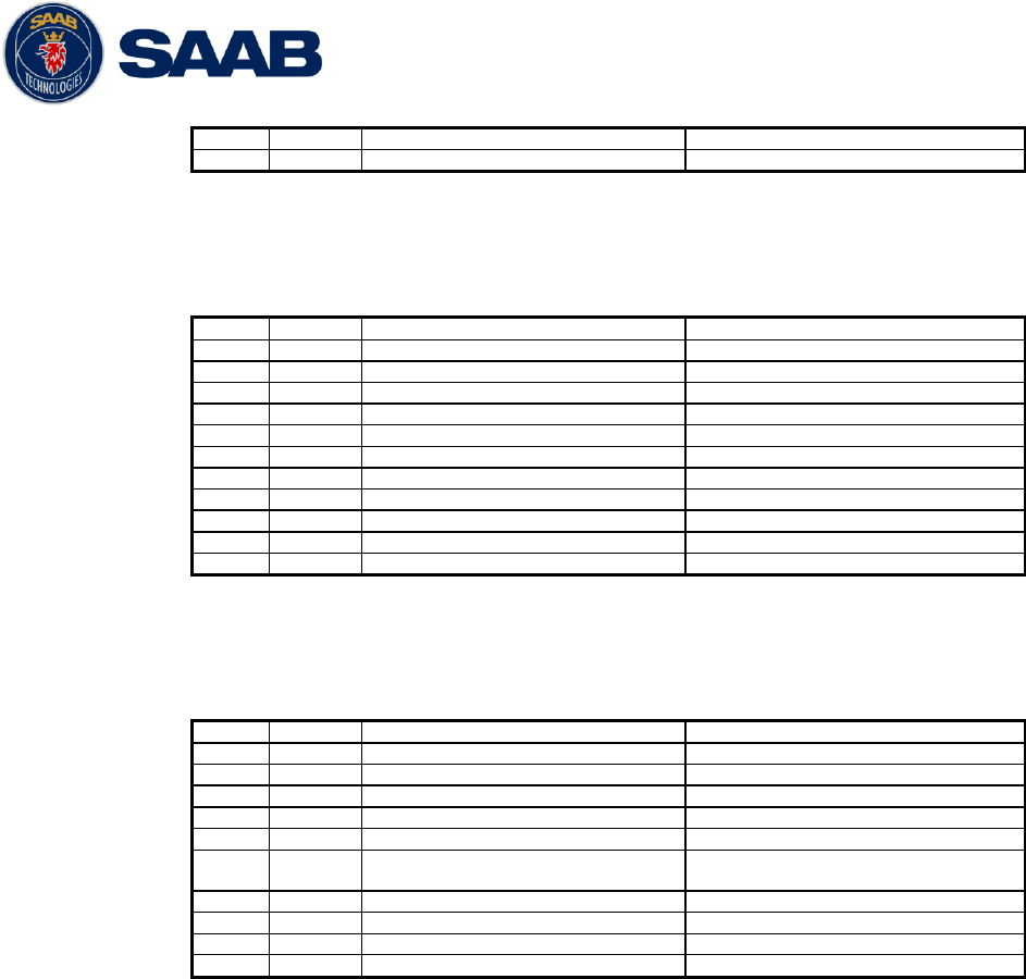
R5 SUPREME AIS System
INTERPRETATION OF OUTPUT SENTENCES
7000 118-300, B1 Page 94
radio message
7
X
Number of fill bits
Used
10.3.11 VER – Version
$--VER,x,x,aa,c--c,c--c,c--c,c--c,c--c,c--c,x
Output rate: On request.
Field
Format
Name
Comment
1
--VER
Sentence Id
Used
2
x
Total number of sentences
Always 1
3
x
Sentence number
Always 1
4
aa
Device Type
Used
5
c--c
Vendor ID
Used
6
c--c
Unique Identifier
Used
7
c--c
Manufacturer serial number
Used
8
c--c
Model code
Used
9
c--c
Software revision
Used
10
c--c
Hardware revision
Used
11
x
Sequential message identifier
Always NULL
10.3.12 VSD – Voyage Static Data
$--VSD,x.x,x.x,x.x,c--c,hhmmss.ss,xx,xx,x.x,x.x
Output rate: On request.
Field
Format
Name
Comment
1
--VSD
Sentence Id
Used
2
x.x
Type of ship and cargo
Used
3
x.x
Maximum present draught
Used
4
x.x
Persons on-board
Used
5
c--c
Destination
Used
6
hhmmss.
ss
Est. UTC of arrival
Used
7
Xx
Est. day of arrival
Used
8
Xx
Est. month of arrival
Used
9
x.x
Navigational status
Used
10
x.x
Regional application flags
Used
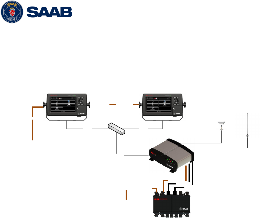
R5 SUPREME AIS System
ALTERNATE SYSTEM SETUPS
7000 118-300, B1 Page 95
11 ALTERNATE SYSTEM SETUPS
11.1 Dual CDU
Additional R5 CDU units can be connected to the same R5 SUPREME transponder, if connected to
the same network.
NOTE: If using two or more CDU units connected to the same transponder, it is important to
only do AIS configuration from one unit at a time. Failure to do so may result in unexpected
results.
R5 AIS Junction Box
Ethernet
External power 12-24 VDC
R5 Transponder
R5 Signal Cable
R5 Signal Cable
R5 Power Cable
R5 CDU in AIS Mode
R5 Power Cable
VHF
GPS
R5 CDU in AIS Mode
EthernetEthernet
IEC 60945 Ethernet Switch
R5 Power Cable
HW Parts in addition to a standard R5 SUPREME AIS kit:
R5 CDU - 7000 118-530
R5 Power Cable, 2m - 7000 118-077
2 x R5 SUPREME Ethernet Cable, 5m - 7000 000-525
Ethernet switch
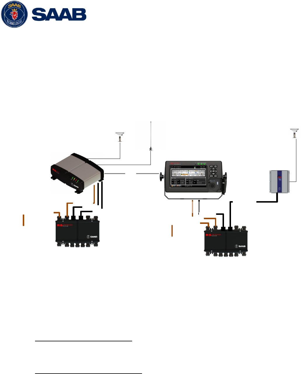
R5 SUPREME AIS System
ALTERNATE SYSTEM SETUPS
7000 118-300, B1 Page 96
11.2 Combined AIS and Navigation system setup
Below details how to install a combined AIS MKD and Navigation system, using one CDU.
The CDU can act as both AIS MKD and Navigation system at the same time. The initial
system setup wizard will activate the correct dialogs and menus.
Running the CDU in this mode will activate many more functions and views in the system,
not detailed in this manual. For information about navigation functions and setup, please
see the navigation system manual: 7000 118-301, R5 SUPREME Navigation System
manual.
R4 GPS Navigation Sensor or
R4 DGPS Navigation Sensor
R5 NAV
Junction Box
R5 NAV Junction Box
R5 NAV Sensor Cable
External power 24 VDC
R5 Signal Cable
R5 Power Cable
R5 AIS Junction Box
Ethernet
External power 12-24 VDC
R5 Transponder
R5 Signal Cable
R5 Signal Cable
R5 Power Cable
VHF
GPS GPS
R5 CDU in Combined AIS and
NAV mode
Figure 46- Combined AIS and Navigation system
HW Parts in addition to a standard R5 SUPREME AIS kit:
R4 Navigation sensor. 7000 109-141(GPS) or 7000 109-140 (DGPS)
R4 Navigation sensor antenna 7000 000-263 (GPS) or 7000 000-359 (DGPS)
R5 NAV Junction box - 7000 118-121 (Optional)
With R5 Nav Junction Box only:
R5 Navigation Sensor Power and Signal Cable, 2m - 7000 118-122
R5 Signal cable DSUB-DSUB, 2m - 7000 118-286
Without R5 Nav Junction Box only:
R4 Navigation Sensor Power and Signal Cable, 2m - 7000 109-011
R5 Signal cable DSUB-OPEN, 2m - 7000 118-078
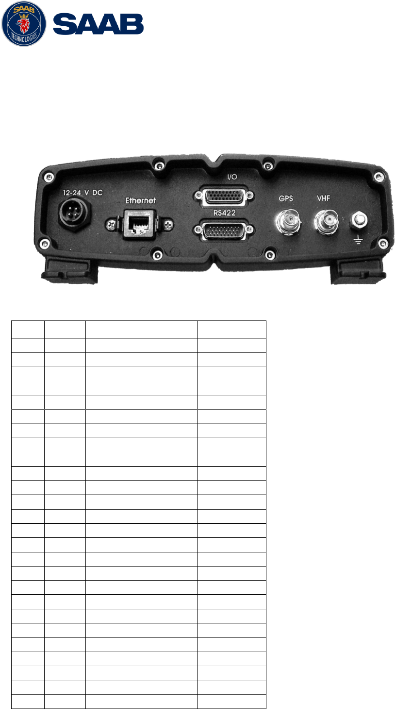
R5 SUPREME AIS System
ELECTRICAL INTERFACES
7000 118-300, B1 Page 97
12 ELECTRICAL INTERFACES
For details in RS-422 Baud rates and Sensor input priority please see section 3.12.1 “Input port
priority”
12.1 Transponder interface details
12.1.1 RS422 port - 26-pole H.D.D-SUB Male
Pin
In/Out
Signal Name
Signal Type
1
Out
ECDIS - TxB (+)
RS422
2
Out
ECDIS - TxA (-)
RS422
3
In
Sensor1 - RxB (+)
RS422
4
In
Sensor1 - RxA (-)
RS422
5
In
Sensor2 - RxB (+)
RS422
6
In
Sensor2 - RxA (-)
RS422
7
In
Long Range - RxB (+)
RS422
8
In
Long Range - RxA (-)
RS422
9
-
Long Range - GND
RS422
10
-
ECDIS - GND
RS422
11
In
ECDIS – RxB (+)
RS422
12
In
ECDIS – RxA (-)
RS422
13
-
Sensor1 – GND
RS422
14
-
Sensor2 – GND
RS422
15
In
Sensor3 – RxB (+)
RS422
16
In
Sensor3 – RxA (-)
RS422
17
Out
Long Range – TxB (+)
RS422
18
Out
Long Range – TxA (-)
RS422
19
-
Alarm Relay – GND
-
20
Out
Alarm Relay – Out
-
21
-
GND
-
22
-
-
-
23
-
Sensor3 – GND
RS422
24
-
Alarm Relay - VCC
-
25
-
-
-
26
-
-
-

R5 SUPREME AIS System
ELECTRICAL INTERFACES
7000 118-300, B1 Page 98
Table 13 – Transponder RS422 Port
12.1.2 I/O port - 26-pole H.D.D-SUB Female
Pin
In/Out
Signal Name
Signal Type
1
Out
Sensor 1 – TxB (+)
RS422
2
Out
Sensor 1 – TxA (-)
RS422
3
-
GND
-
4
-
GND
-
5
Out
Sensor 2 – TxA (-)
RS422
6
Out
Sensor 2 – TxB (+)
RS422
7
Out
Sensor 3 – TxA (-)
RS422
8
Out
Sensor 3 – TxB (+)
RS422
9
In
SW LOAD
Binary
10
-
GND
-
11
In/Out
USB Host (-)
Differential USB
12
In/Out
USB Host (+)
Differential USB
13
-
USB Host VCC
-
14
-
GND
-
15
In
Pilot Port – RxA (-)
RS422
16
In
Pilot Port – RxB (+)
RS422
17
Out
Pilot Port – TxA (-)
RS422
18
Out
Pilot Port – TxB (+)
RS422
19
In
General I/O 3 – In
Binary
20
Out
General I/O 0 – Out
Binary
21
In
General I/O 2 – In
Binary
22
Out
General I/O 1 – Out
Binary
23
In
General I/O 1 – In
Binary
24
Out
General I/O 2 – Out
Binary
25
Out
General I/O 3 – Out
Binary
26
In
General I/O 0 – In
Binary
Table 14 – I/O Transponder Port
12.1.3 Power port
Pin
In/Out
Signal Name
Signal Type
1
In
PWR +
24 VDC
2
In
PWG GND
0 VDC
3
In
Ext Switch R
See instr.
4
In
Ext Switch F
See instr.
12.1.4 Ethernet port – RJ-45 100 MBit – IEC 61162-450
12.1.5 GPS port - TNC (Female) - 5 VDC
12.1.6 VHF port - BNC (Female)
12.1.7 GND Screw – M6
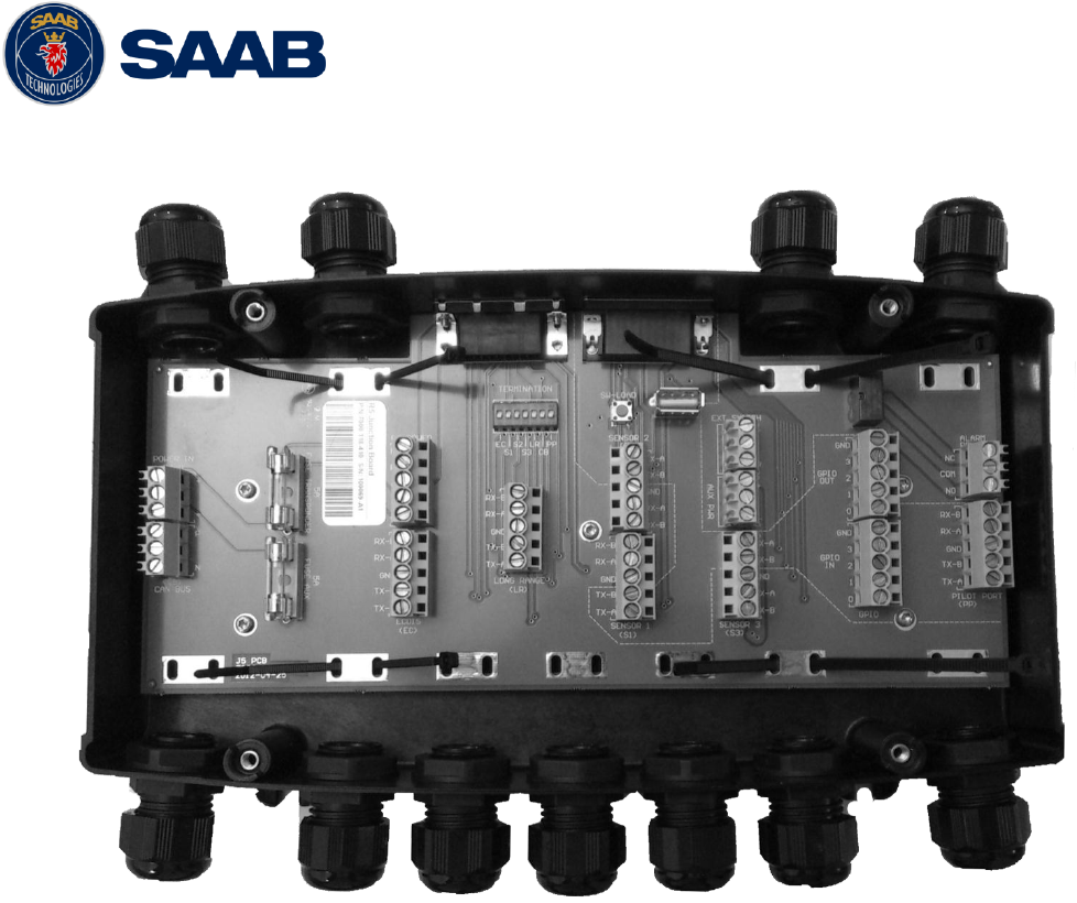
R5 SUPREME AIS System
ELECTRICAL INTERFACES
7000 118-300, B1 Page 99
12.2 R5 AIS Junction box Interfaces
Figure 47 – R5 AIS Junction box
12.2.1 External ports:
12.2.1.1.1 26 pin DSUB Female port:
Connects R5 Signal Cable DSUB-DSUB to Transponder “RS422”
12.2.1.1.2 26 pin DSUB Male port:
Connects reversed R5 Signal Cable DSUB-DSUB to Transponder “I/O”
12.2.1.1.3 Cable gland ports:
M20: Will fit 6-12 mm cables. For larger cables please unscrew the cable
gland. See description of internal connectors below.
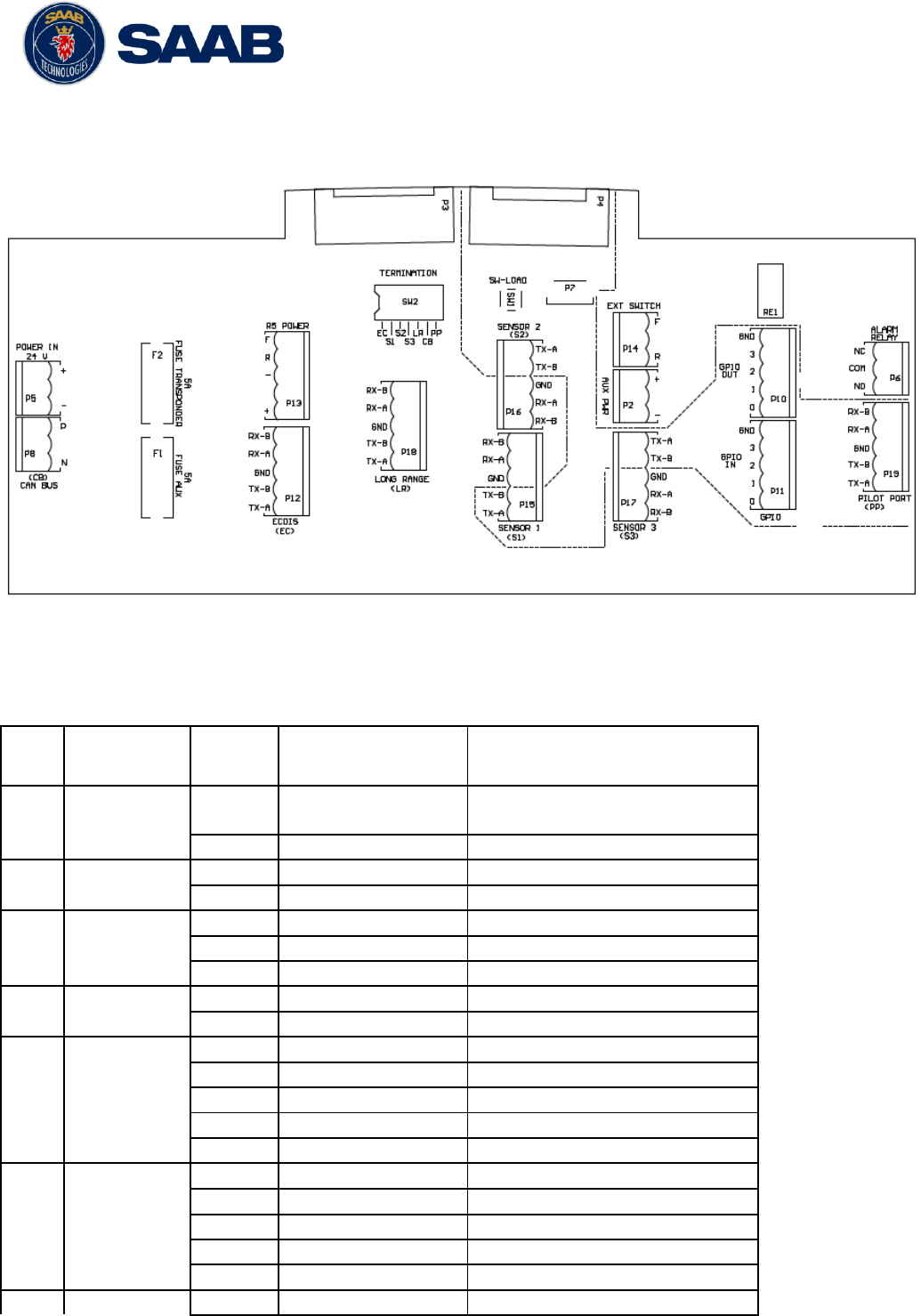
R5 SUPREME AIS System
ELECTRICAL INTERFACES
7000 118-300, B1 Page 100
12.2.2 Internal Screw terminals and components
Figure 48 – Circuit Board Layout and markings
The table below details all the screw terminal connections when connected with two R5
Signal Cables to an R5 SUPREME Transponder
Item1
Terminal
Marking
Pin
Marking
Signal
Connects to
P2
AUX PWR
+
Ext Power In by
AUX PWR FUSE
CDU R5 Power Cable Red
-
Power In -
CDU R5 Power Cable Black
P5
POWER IN
+
Ext Power In +
External power
-
Ext Power In -
External power
P6
ALARM RELAY
NC
Alarm Relay NC
Junction box Alarm relay
COM
Alarm Relay COM
Junction box Alarm relay
NO
Alarm Relay NO
Junction box Alarm relay
P8
CAN BUS
P
CAN Bus P
R5 RS422 Pin 25
N
CAN Bus N
R5 RS422 Pin 26
P10
GPIO OUT
0
GPIO OUT 0
R5 I/O Pin 20
1
GPIO OUT 1
R5 I/O Pin 22
2
GPIO OUT 2
R5 I/O Pin 24
3
GPIO OUT 3
R5 I/O Pin 25
GND
GPIO OUT GND
R5 I/O Pin 3
P11
GPIO IN
0
GPIO IN 0
R5 I/O Pin 26
1
GPIO IN 1
R5 I/O Pin 23
2
GPIO IN 2
R5 I/O Pin 21
3
GPIO IN 3
R5 I/O Pin 19
GND
GPIO IN GND
R5 I/O Pin 3
P12
ECDIS
TX-A
ECDIS TX-A
R5 RS422 Pin 2

R5 SUPREME AIS System
ELECTRICAL INTERFACES
7000 118-300, B1 Page 101
Item1
Terminal
Marking
Pin
Marking
Signal
Connects to
TX-B
ECDIS TX-B
R5 RS422 Pin 1
GND
ECDIS GND
R5 RS422 Pin 10
RX-A
ECDIS RX-A
R5 RS422 Pin
RX-B
ECDIS RX-B
R5 RS422 Pin
P13
R5 POWER
+
R5 Power +
Transponder R5 Power Cable Red
-
R5 Power -
Transponder R5 Power Cable Black
R
R5 Power R
Transponder R5 Power Cable
Brown
F
R5 Power F
Transponder R5 Power Cable
Orange
P14
EXT SWITCH
F
Ext Switch F
Terminal
R5 power F
R
Ext Switch R
Terminal
R5 power R
P15
SENSOR 1
TX-A
Sensor 1 TX-A
R5 I/O pin 2
TX-B
Sensor 1 TX-B
R5 I/O pin 1
GND
Sensor 1 GND
R5 RS422 Pin 13
RX-A
Sensor 1 RX-A
R5 RS422 Pin 4
RX-B
Sensor 1 RX-B
R5 RS422 Pin 3
P16
SENSOR 2
TX-A
Sensor 2 TX-A
R5 I/O pin 5
TX-B
Sensor 2 TX-B
R5 I/O pin 6
GND
Sensor 2 GND
R5 RS422 Pin 14
RX-A
Sensor 2 RX-A
R5 RS422 Pin 6
RX-B
Sensor 2 RX-B
R5 RS422 Pin 5
P17
SENSOR 3
TX-A
Sensor 3 TX-A
R5 I/O pin 7
TX-B
Sensor 3 TX-B
R5 I/O pin 8
GND
Sensor 3 GND
R5 RS422 Pin 23
RX-A
Sensor 3 RX-A
R5 RS422 Pin 16
RX-B
Sensor 3 RX-B
R5 RS422 Pin 15
P18
LONG RANGE
TX-A
Long Range TX-A
R5 RS422 Pin 18
TX-B
Long Range TX-B
R5 RS422 Pin 17
GND
Long Range GND
R5 RS422 Pin 9
RX-A
Long Range RX-A
R5 RS422 Pin 8
RX-B
Long Range RX-B
R5 RS422 Pin 7
P19
PILOT PORT
TX-A
Pilot Port TX-A
R5 I/O pin 17
TX-B
Pilot Port TX-B
R5 I/O pin 18
GND
Pilot Port GND
R5 I/O pin 4
RX-A
Pilot Port RX-A
R5 I/O pin 15
RX-B
Pilot Port RX-B
R5 I/O pin 16
Table 15 - Screw terminals
R5 SUPREME AIS System
ELECTRICAL INTERFACES
7000 118-300, B1 Page 102
Below table details additional components in the Junctionbox
Item
Description
SW2
Termination Switches for ECDIS, Sensor 1, Sensor 2, Sensor
3, Long Range, CAN Bus and Pilot Port
SW1
Push-button for Software Load
P3
D-SUB Connector for R5 Signal Cable connected to
transponder port RS422
P4
D-SUB Connector for R5 Signal Cable connected to
transponder port I/O
P7
USB connector for Software Upgrade of Transponder
F1
5A fuse for AUX PWR
F2
5A fuse for R5 POWER
Table 16 - Additional Junction box components
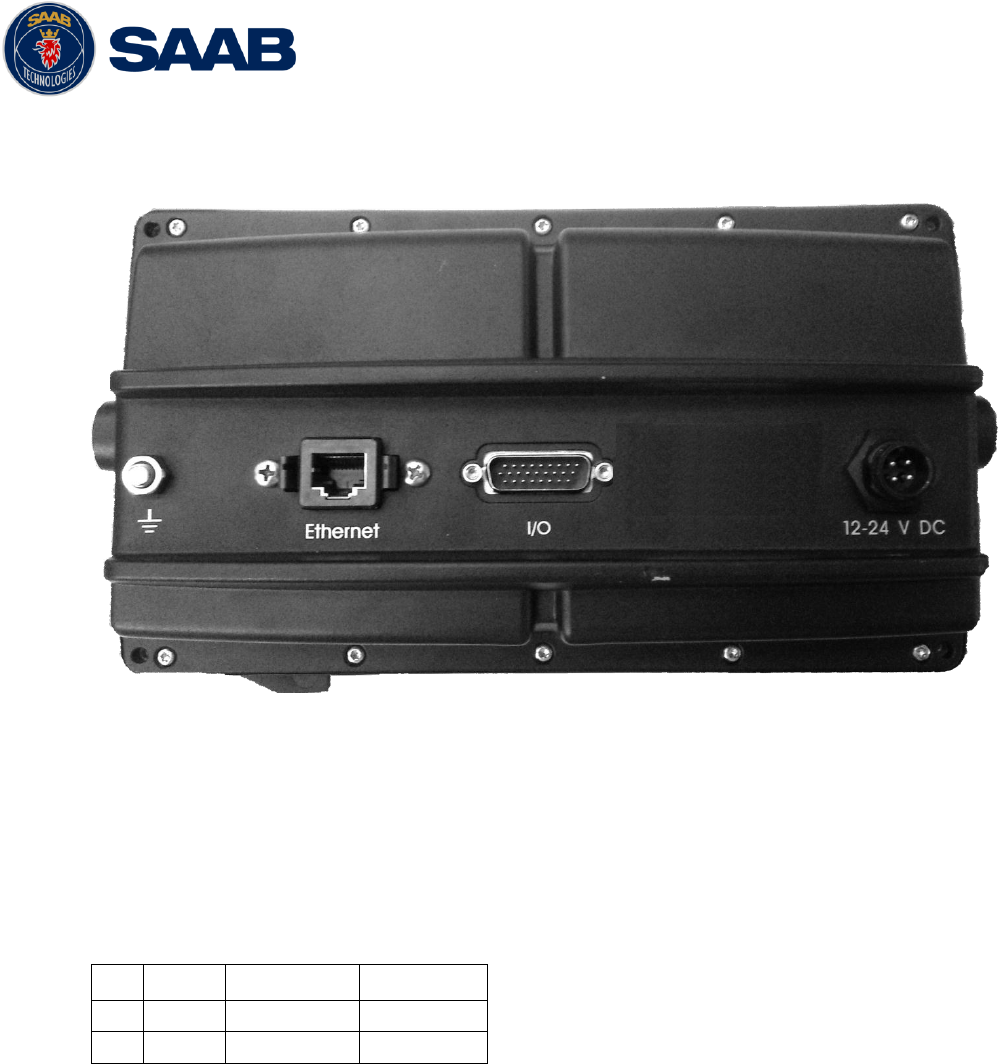
R5 SUPREME AIS System
ELECTRICAL INTERFACES
7000 118-300, B1 Page 103
12.3 CDU Interfaces:
12.3.1 CDU Back:
12.3.1.1 Ethernet port – RJ-45 100 MBit – IEC 61162-450
12.3.1.2 I/O port - 26-pole H.D.D-SUB Female
Only used in Combination with R4 Navigation Sensor installations.
12.3.1.3 GND Screw – M6
12.3.1.4 Power port
Pin
In/Out
Signal Name
Signal Type
1
In
PWR +
24 VDC
2
In
PWG GND
0 VDC
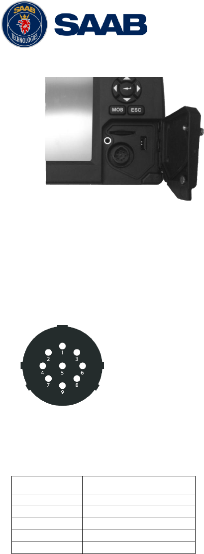
R5 SUPREME AIS System
ELECTRICAL INTERFACES
7000 118-300, B1 Page 104
12.3.2 CDU Front hatch:
Figure 49- CDU Front ports
12.3.2.1 USB Host Type A
USB 2.0.
12.3.2.2 CDU Pilot Plug RS-422
This bi-directional port is routed over ethenet to the Transpodner.
Figure 50 - CDU Pilot plug pin numbering
Pilot plug
Signal Type
PIN 9
RS-422 GND
PIN 1
RS-422 TX-A
PIN 5
RS-422 RX-A
PIN 4
RS-422 TX-B
PIN 6
RS-422 RX-B
Table 17 – CDU Pilot port signals
12.3.3 Secure Digital Card Reader
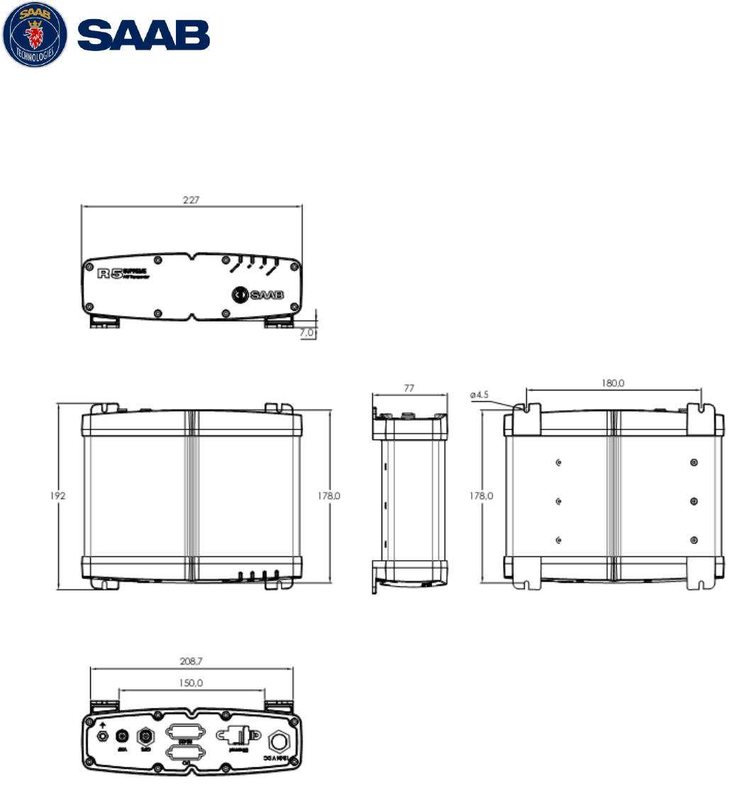
R5 SUPREME AIS System
MECHANICAL DRAWINGS
7000 118-300, B1 Page 105
13 MECHANICAL DRAWINGS
13.1 Transponder Physical Size and Mechanical Drawing
Figure 51 – R5 SUPREME Transponder, Dimensions
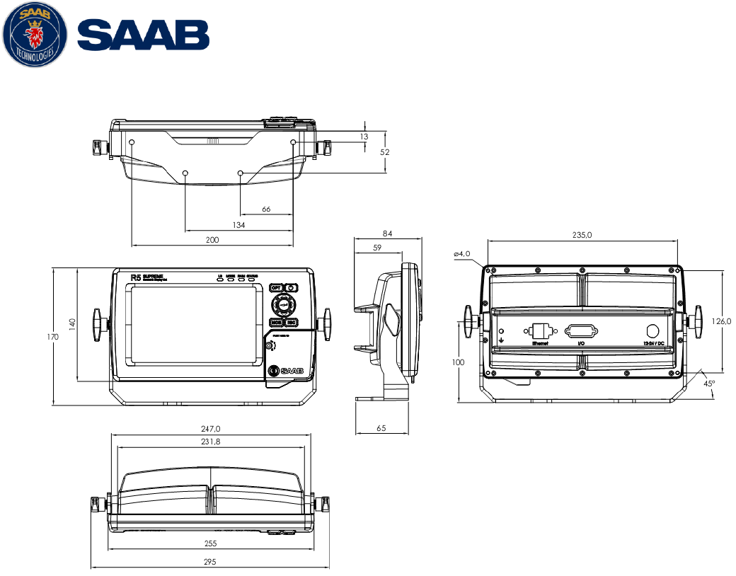
R5 SUPREME AIS System
MECHANICAL DRAWINGS
7000 118-300, B1 Page 106
13.2 CDU Physical Size and Mechanical Drawing
Figure 52 – R5 SUPREME CDU Mechanical Drawing (mm)
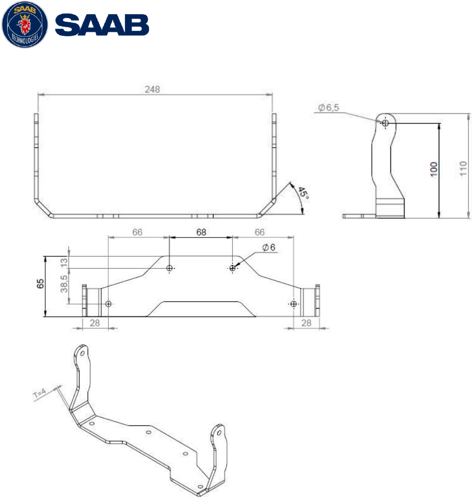
R5 SUPREME AIS System
MECHANICAL DRAWINGS
7000 118-300, B1 Page 107
13.3 CDU Gimbal Mount Physical Size and Mechanical Drawing
Figure 53 – R5 SUPREME CDU, Gimbal Mount
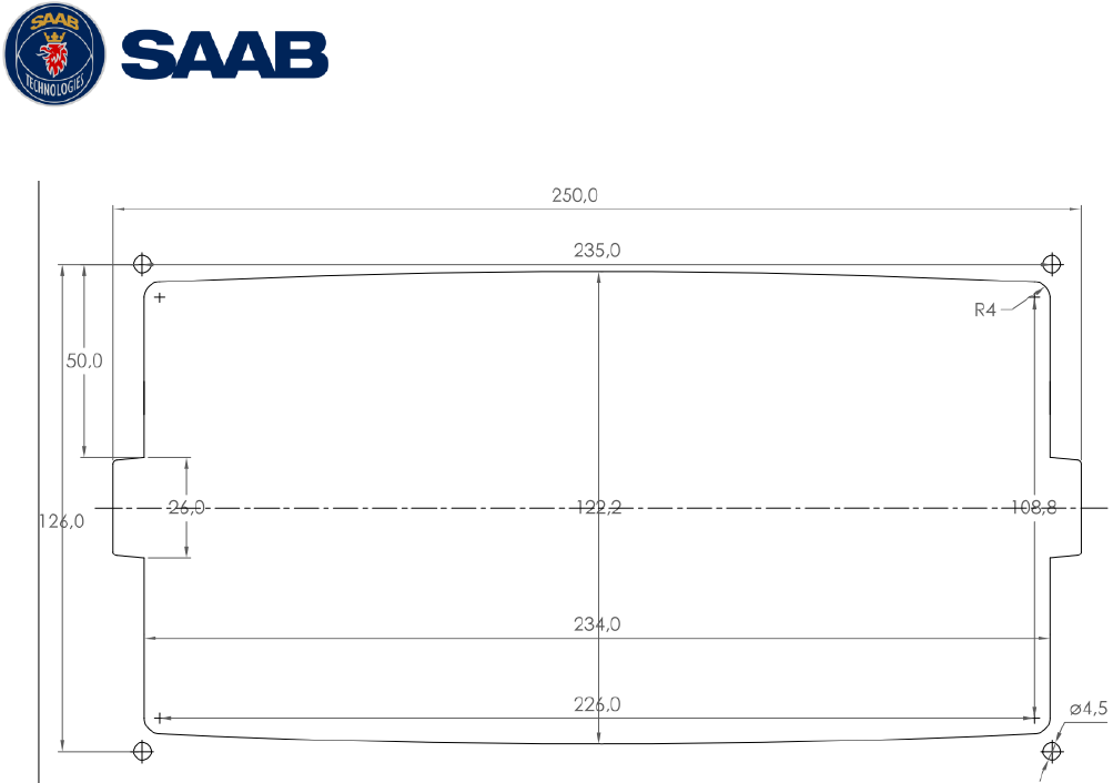
R5 SUPREME AIS System
MECHANICAL DRAWINGS
7000 118-300, B1 Page 108
13.4 CDU Cutout Measurements for Panel Mount
Figure 54 – R5 SUPREME CDU, Cutout Measurements for Panel Mount [mm]
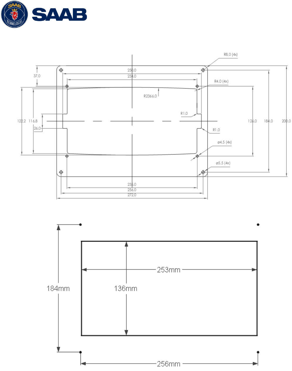
R5 SUPREME AIS System
MECHANICAL DRAWINGS
7000 118-300, B1 Page 109
13.5 CDU Mounting Frame cutout and dimensions
Figure 55 – R5 SUPREME CDU, Mounting frame dimensions
Figure 56 – R5 SUPREME CDU, Cutout Measurements for Panel Flush Mount (mm)
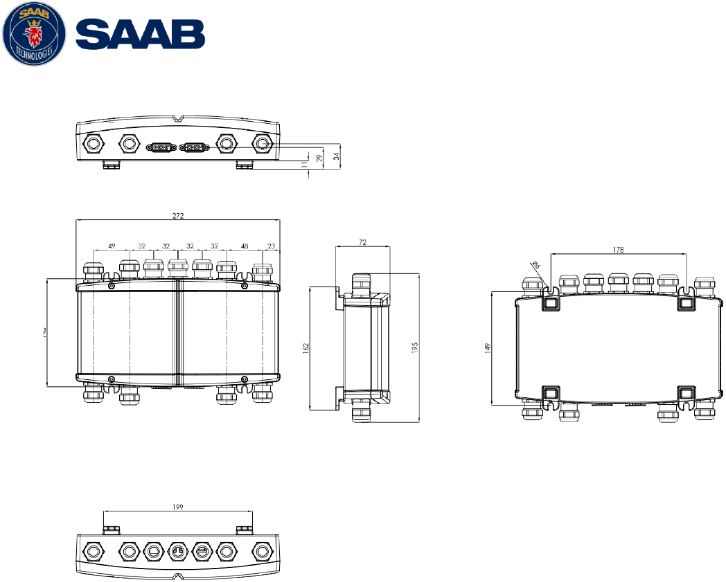
R5 SUPREME AIS System
MECHANICAL DRAWINGS
7000 118-300, B1 Page 110
13.6 R5 AIS Junction Box Physical Size and Mechanical Drawing
Figure 57 – R5 AIS Junction Box, Dimensions (mm)
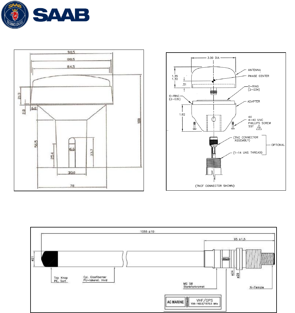
R5 SUPREME AIS System
MECHANICAL DRAWINGS
7000 118-300, B1 Page 111
13.7 GPS Antenna – Physical Size and Mechanical Drawing
Figure 60 – Combined VHF / GPS Antenna – AC Marine
Figure 59 – GPS Antenna – AT575-68
Figure 58 – GPS Antenna – MA700

R5 SUPREME AIS System
GLOSSARY
7000 118-300, B1 Page 112
14 GLOSSARY
ACK
Acknowledgement
AFSK
Audio Frequency Shift Keying
AIS
Automatic Identification System
Ant
Antenna
App
Application
ARPA
Automatic Radar Plotting Aid
BRG
Bearing
BS
Base Station
CDU
Control and Display Unit
Ch
Channel
COG
Course Over Ground
Comm
Communication
DGNSS
Differential Global Navigational Satellite System
Disp
Display
DTE
Data Terminal Equipment
DSC
Digital Selective Calling
ECDIS
Electronic Chart Display and Information System
EGNOS
European Geostationary Navigation Overlay Service
EPFS
Electronic Position Fixing System
ETA
Estimated Time of Arrival
Ext
External
GALILEO
European GNSS
GLONASS
Russian GNSS
GMSK
Gaussian Minimum Shift Keying
GNSS
Global Navigational Satellite System
GPS
Global Positioning System
HDG
Heading
HDOP
Horizontal Dilution Of Precision
H/W
Hardware
IALA
International Association of Lighthouse Authorities
ID
Identifier
IEC
International Electrotechnical Commission
IMO
International Maritime Organization
Int
Internal
IP
Internet Protocol (adress)
ITU
International Telecommunications Union
LAT
Latitude

R5 SUPREME AIS System
GLOSSARY
7000 118-300, B1 Page 113
LED
Light Emitting Diode
LOC
Local
LON
Longitude
LR
Long Range
LWE
Light Weight Ethernet
Msg
Message
MKD
Minimum Keyboard and Display
MSAS
MTSAT Satellite Augmentation System (Japan)
NMEA
National Marine Electronics Association
MMSI
Maritime Mobile Service Identity
N/A
Not available
NE
North East
No
Number
NVM
Non-Volatile Memory
PoB
Persons on board
Pos
Position
RAIM
Receiver Autonomous Integrity Monitoring
RNG
Range
RATDMA
Random Access Time Division Multiple Access
ROT
Rate Of Turn
RTA
Recommended Time of Arrival
Rx
Receive
SAR
Search And Rescue
SART
Search And Rescue Transmitter
SBAS
Satellite Based Augmentation System
SNR
Signal to Noise Ratio
SOG
Speed Over Ground
SRM
Safety Related Message
Sync
Synchronization
SW
South West
S/W
Software
TDMA
Time Division Multiple Access
Transp
Transponder
Tx
Transmit
UN
United Nations
UTC
Universal Time Coordinated
VHF
Very High Frequency
VSWR
Voltage Standing Wave Ratio. (A low value indicates a problem with the antenna or
connections/cables to the antenna.)

R5 SUPREME AIS System
GLOSSARY
7000 118-300, B1 Page 114
WAAS
Wide Area Augmentation System (United States)
14.1 Units
bps
Bits per second
W
Watt
m
Meter
kHz
Kilo Hertz
dB-Hz
Decibel-Hertz
NM
Nautical Mile
km
Kilometer
Sm
Statute Mile
kn
Knots
km/h
Kilometer per Hour
mph
Miles per Hour
mm-dd hh:mm
month-day hour:minute
h:m:s
hours:minutes:seconds

R5 SUPREME AIS System
APPENDIX A – LICENSE
7000 118-300, B1 Page 115
15 APPENDIX A – LICENSE
The R5 SUPREME AIS Transponder System runs on a Linux operating system which is licensed
with GNU General Public License. The source code of the linux kernel can be obtained by
contacting Saab TransponderTech AB:
Saab TransponderTech
Låsblecksgatan 3
589 31 Linköping
Sweden
Email: support.transpondetech@saabgroup.com
15.1 Copy of the GNU General Public License
GNU GENERAL PUBLIC LICENSE
Version 2, June 1991
Copyright (C) 1989, 1991 Free Software Foundation, Inc. 51 Franklin St, Fifth Floor, Boston, MA 02110-1301 USA
Everyone is permitted to copy and distribute verbatim copies of this license document, but changing it is not allowed.
Preamble
The licenses for most software are designed to take away your freedom to share and change it. By contrast, the GNU General Public License is intended to guarantee your freedom to
share and change free software--to make sure the software is free for all its users. This General Public License applies to most of the Free Software Foundation's software and to any
other program whose authors commit to using it. (Some other Free Software Foundation software is covered by the GNU Library General Public License instead.) You can apply it to
your programs, too.
When we speak of free software, we are referring to freedom, not price. Our General Public Licenses are designed to make sure that you have the freedom to distribute copies of free
software (and charge for this service if you wish), that you receive source code or can get it if you want it, that you can change the software or use pieces of it in new free programs; and
that you know you can do these things.
To protect your rights, we need to make restrictions that forbid anyone to deny you these rights or to ask you to surrender the rights. These restrictions translate to certain
responsibilities for you if you distribute copies of the software, or if you modify it.
For example, if you distribute copies of such a program, whether gratis or for a fee, you must give the recipients all the rights that you have. You must make sure that they, too, receive
or can get the source code. And you must show them these terms so they know their rights.
We protect your rights with two steps: (1) copyright the software, and (2) offer you this license which gives you legal permission to copy, distribute and/or modify the software.
Also, for each author's protection and ours, we want to make certain that everyone understands that there is no warranty for this free software. If the software is modified by someone
else and passed on, we want its recipients to know that what they have is not the original, so that any problems introduced by others will not reflect on the original authors' reputations.
Finally, any free program is threatened constantly by software patents. We wish to avoid the danger that redistributors of a free program will individually obtain patent licenses, in effect
making the program proprietary. To prevent this, we have made it clear that any patent must be licensed for everyone's free use or not licensed at all.
The precise terms and conditions for copying, distribution and modification follow.
GNU GENERAL PUBLIC LICENSE
TERMS AND CONDITIONS FOR COPYING, DISTRIBUTION AND MODIFICATION
0. This License applies to any program or other work which contains a notice placed by the copyright holder saying it may be distributed under the terms of this General Public License.
The "Program", below, refers to any such program or work, and a "work based on the Program" means either the Program or any derivative work under copyright law: that is to say, a
work containing the Program or a portion of it, either verbatim or with modifications and/or translated into another language. (Hereinafter, translation is included without limitation in the
term "modification".) Each licensee is addressed as "you".
Activities other than copying, distribution and modification are not covered by this License; they are outside its scope. The act of running the Program is not restricted, and the output
from the Program is covered only if its contents constitute a work based on the Program (independent of having been made by running the Program). Whether that is true depends on
what the Program does.
1. You may copy and distribute verbatim copies of the Program's source code as you receive it, in any medium, provided that you conspicuously and appropriately publish on each copy
an appropriate copyright notice and disclaimer of warranty; keep intact all the notices that refer to this License and to the absence of any warranty; and give any other recipients of the
Program a copy of this License along with the Program.
You may charge a fee for the physical act of transferring a copy, and you may at your option offer warranty protection in exchange for a fee.
2. You may modify your copy or copies of the Program or any portion of it, thus forming a work based on the Program, and copy and distribute such modifications or work under the
terms of Section 1 above, provided that you also meet all of these conditions:
i. You must cause the modified files to carry prominent notices stating that you changed the files and the date of any change.
ii. You must cause any work that you distribute or publish, that in whole or in part contains or is derived from the Program or any part thereof, to be licensed as a whole at no charge
to all third parties under the terms of this License.
iii. If the modified program normally reads commands interactively when run, you must cause it, when started running for such interactive use in the most ordinary way, to print or
display an announcement including an appropriate copyright notice and a notice that there is no warranty (or else, saying that you provide a warranty) and that users may
redistribute the program under these conditions, and telling the user how to view a copy of this License. (Exception: if the Program itself is interactive but does not normally print
such an announcement, your work based on the Program is not required to print an announcement.)
These requirements apply to the modified work as a whole. If identifiable sections of that work are not derived from the Program, and can be reasonably considered independent and
separate works in themselves, then this License, and its terms, do not apply to those sections when you distribute them as separate works. But when you distribute the same sections
as part of a whole which is a work based on the Program, the distribution of the whole must be on the terms of this License, whose permissions for other licensees extend to the entire
whole, and thus to each and every part regardless of who wrote it.

R5 SUPREME AIS System
APPENDIX A – LICENSE
7000 118-300, B1 Page 116
Thus, it is not the intent of this section to claim rights or contest your rights to work written entirely by you; rather, the intent is to exercise the right to control the distribution of derivative
or collective works based on the Program.
In addition, mere aggregation of another work not based on the Program with the Program (or with a work based on the Program) on a volume of a storage or distribution medium does
not bring the other work under the scope of this License.
3. You may copy and distribute the Program (or a work based on it, under Section 2) in object code or executable form under the terms of Sections 1 and 2 above provided that you also
do one of the following:
a) Accompany it with the complete corresponding machine-readable source code, which must be distributed under the terms of Sections 1 and 2 above on a medium customarily
used for software interchange; or,
b) Accompany it with a written offer, valid for at least three years, to give any third party, for a charge no more than your cost of physically performing source distribution, a complete
machine-readable copy of the corresponding source code, to be distributed under the terms of Sections 1 and 2 above on a medium customarily used for software interchange;
or,
c) Accompany it with the information you received as to the offer to distribute corresponding source code. (This alternative is allowed only for noncommercial distribution and only if
you received the program in object code or executable form with such an offer, in accord with Subsection b above.)
The source code for a work means the preferred form of the work for making modifications to it. For an executable work, complete source code means all the source code for all
modules it contains, plus any associated interface definition files, plus the scripts used to control compilation and installation of the executable. However, as a special exception, the
source code distributed need not include anything that is normally distributed (in either source or binary form) with the major components (compiler, kernel, and so on) of the operating
system on which the executable runs, unless that component itself accompanies the executable.
If distribution of executable or object code is made by offering access to copy from a designated place, then offering equivalent access to copy the source code from the same place
counts as distribution of the source code, even though third parties are not compelled to copy the source along with the object code.
4. You may not copy, modify, sublicense, or distribute the Program except as expressly provided under this License. Any attempt otherwise to copy, modify, sublicense or distribute the
Program is void, and will automatically terminate your rights under this License. However, parties who have received copies, or rights, from you under this License will not have their
licenses terminated so long as such parties remain in full compliance.
5. You are not required to accept this License, since you have not signed it. However, nothing else grants you permission to modify or distribute the Program or its derivative works.
These actions are prohibited by law if you do not accept this License. Therefore, by modifying or distributing the Program (or any work based on the Program), you indicate your
acceptance of this License to do so, and all its terms and conditions for copying, distributing or modifying the Program or works based on it.
6. Each time you redistribute the Program (or any work based on the Program), the recipient automatically receives a license from the original licensor to copy, distribute or modify the
Program subject to these terms and conditions. You may not impose any further restrictions on the recipients' exercise of the rights granted herein. You are not responsible for enforcing
compliance by third parties to this License.
7. If, as a consequence of a court judgment or allegation of patent infringement or for any other reason (not limited to patent issues), conditions are imposed on you (whether by court
order, agreement or otherwise) that contradict the conditions of this License, they do not excuse you from the conditions of this License. If you cannot distribute so as to satisfy
simultaneously your obligations under this License and any other pertinent obligations, then as a consequence you may not distribute the Program at all. For example, if a patent license
would not permit royalty-free redistribution of the Program by all those who receive copies directly or indirectly through you, then the only way you could satisfy both it and this License
would be to refrain entirely from distribution of the Program.
If any portion of this section is held invalid or unenforceable under any particular circumstance, the balance of the section is intended to apply and the section as a whole is intended to
apply in other circumstances.
It is not the purpose of this section to induce you to infringe any patents or other property right claims or to contest validity of any such claims; this section has the sole purpose of
protecting the integrity of the free software distribution system, which is implemented by public license practices. Many people have made generous contributions to the wide range of
software distributed through that system in reliance on consistent application of that system; it is up to the author/donor to decide if he or she is willing to distribute software through any
other system and a licensee cannot impose that choice.
This section is intended to make thoroughly clear what is believed to be a consequence of the rest of this License.
8. If the distribution and/or use of the Program is restricted in certain countries either by patents or by copyrighted interfaces, the original copyright holder who places the Program under
this License may add an explicit geographical distribution limitation excluding those countries, so that distribution is permitted only in or among countries not thus excluded. In such
case, this License incorporates the limitation as if written in the body of this License.
9. The Free Software Foundation may publish revised and/or new versions of the General Public License from time to time. Such new versions will be similar in spirit to the present
version, but may differ in detail to address new problems or concerns.
Each version is given a distinguishing version number. If the Program specifies a version number of this License which applies to it and "any later version", you have the option of
following the terms and conditions either of that version or of any later version published by the Free Software Foundation. If the Program does not specify a version number of this
License, you may choose any version ever published by the Free Software Foundation.
10. If you wish to incorporate parts of the Program into other free programs whose distribution conditions are different, write to the author to ask for permission. For software which is
copyrighted by the Free Software Foundation, write to the Free Software Foundation; we sometimes make exceptions for this. Our decision will be guided by the two goals of preserving
the free status of all derivatives of our free software and of promoting the sharing and reuse of software generally.
NO WARRANTY
11. BECAUSE THE PROGRAM IS LICENSED FREE OF CHARGE, THERE IS NO WARRANTY FOR THE PROGRAM, TO THE EXTENT PERMITTED BY APPLICABLE LAW.
EXCEPT WHEN OTHERWISE STATED IN WRITING THE COPYRIGHT HOLDERS AND/OR OTHER PARTIES PROVIDE THE PROGRAM "AS IS" WITHOUT WARRANTY OF ANY
KIND, EITHER EXPRESSED OR IMPLIED, INCLUDING, BUT NOT LIMITED TO, THE IMPLIED WARRANTIES OF MERCHANTABILITY AND FITNESS FOR A PARTICULAR
PURPOSE. THE ENTIRE RISK AS TO THE QUALITY AND PERFORMANCE OF THE PROGRAM IS WITH YOU. SHOULD THE PROGRAM PROVE DEFECTIVE, YOU ASSUME
THE COST OF ALL NECESSARY SERVICING, REPAIR OR CORRECTION.
12. IN NO EVENT UNLESS REQUIRED BY APPLICABLE LAW OR AGREED TO IN WRITING WILL ANY COPYRIGHT HOLDER, OR ANY OTHER PARTY WHO MAY MODIFY
AND/OR REDISTRIBUTE THE PROGRAM AS PERMITTED ABOVE, BE LIABLE TO YOU FOR DAMAGES, INCLUDING ANY GENERAL, SPECIAL, INCIDENTAL OR
CONSEQUENTIAL DAMAGES ARISING OUT OF THE USE OR INABILITY TO USE THE PROGRAM (INCLUDING BUT NOT LIMITED TO LOSS OF DATA OR DATA BEING
RENDERED INACCURATE OR LOSSES SUSTAINED BY YOU OR THIRD PARTIES OR A FAILURE OF THE PROGRAM TO OPERATE WITH ANY OTHER PROGRAMS), EVEN IF
SUCH HOLDER OR OTHER PARTY HAS BEEN ADVISED OF THE POSSIBILITY OF SUCH DAMAGES.
END OF TERMS AND CONDITIONS
How to Apply These Terms to Your New Programs
If you develop a new program, and you want it to be of the greatest possible use to the public, the best way to achieve this is to make it free software which everyone can
redistribute and change under these terms.
To do so, attach the following notices to the program. It is safest to attach them to the start of each source file to most effectively convey the exclusion of warranty; and
each file should have at least the "copyright" line and a pointer to where the full notice is found.
<one line to give the program's name and a brief idea of what it does.>
Copyright (C) <year> <name of author>
This program is free software; you can redistribute it and/or modify
it under the terms of the GNU General Public License as published by
the Free Software Foundation; either version 2 of the License, or
(at your option) any later version.

R5 SUPREME AIS System
APPENDIX A – LICENSE
7000 118-300, B1 Page 117
This program is distributed in the hope that it will be useful,
but WITHOUT ANY WARRANTY; without even the implied warranty of
MERCHANTABILITY or FITNESS FOR A PARTICULAR PURPOSE. See the
GNU General Public License for more details.
You should have received a copy of the GNU General Public License
along with this program; if not, write to the Free Software
Foundation, Inc., 51 Franklin St, Fifth Floor, Boston, MA 02110-1301 USA
Also add information on how to contact you by electronic and paper mail.
If the program is interactive, make it output a short notice like this when it starts in an interactive mode:
Gnomovision version 69, Copyright (C) year name of author
Gnomovision comes with ABSOLUTELY NO WARRANTY; for details type `show w'.
This is free software, and you are welcome to redistribute it
under certain conditions; type `show c' for details.
The hypothetical commands `show w' and `show c' should show the appropriate parts of the General Public License. Of course, the commands you use may be called
something other than `show w' and `show c'; they could even be mouse-clicks or menu items--whatever suits your program.
You should also get your employer (if you work as a programmer) or your school, if any, to sign a "copyright disclaimer" for the program, if necessary. Here is a sample;
alter the names:
Yoyodyne, Inc., hereby disclaims all copyright interest in the program
`Gnomovision' (which makes passes at compilers) written by James Hacker.
<signature of Ty Coon>, 1 April 1989
Ty Coon, President of Vice
This General Public License does not permit incorporating your program into proprietary programs. If your program is a subroutine library, you may consider it more
useful to permit linking proprietary applications with the library. If this is what you want to do, use the GNU Library General Public License instead of this License.