SenTech EAS AQUILA User Manual Basic Description Receiver Electronics
SenTech EAS Corporation Basic Description Receiver Electronics
Contents
- 1. receiver manual
- 2. transmitter manual
receiver manual

URB-100 Tuning Guide
LUCATRON AG
CH-8606 Greifensee, Switzerland Version 2 Page 1
R
RX
X
T
TU
UN
NI
IN
NG
G
G
GU
UI
ID
DE
E

URB-100 Tuning Guide
LUCATRON AG
CH-8606 Greifensee, Switzerland Version 2 Page 2
Table of Contents
Page
1. Basic Description, Receiver Electronics.................................................................................3
1.1. Analog Part.....................................................................................................................3
1.2. Digital Part ......................................................................................................................3
1.3. Power
/
Alarm Part...........................................................................................................4
2. Description of Features............................................................................................................4
2.1. Manually Adjustable RF Gain..........................................................................................4
2.2. Air Synchronization .........................................................................................................4
2.3. Synchronous Demodulator..............................................................................................4
2.4. Beat Note Filter...............................................................................................................4
2.5. Software Click Filter with Adaptive Slope ........................................................................4
2.6. Software Spike Blanker...................................................................................................4
2.7. Accept Counter ...............................................................................................................5
2.8. Threshold Calculation .....................................................................................................5
2.9. Alarm Threshold Margin Settings ....................................................................................5
3. Tuning........................................................................................................................................6
3.1. Philosophy ......................................................................................................................6
3.2. Recommended Tools......................................................................................................6
3.3. Receiver Preparatory Steps ............................................................................................6
3.3.1. Preparation.........................................................................................................6
3.4. Receiver Tuning..............................................................................................................8
3.4.1. RF Gain Adjustment............................................................................................8
3.4.2. Beat Note Adjustment .......................................................................................10
3.4.3. Signal
/
Noise Level Check ................................................................................11
3.4.4. DIL Switch Settings ..........................................................................................12
3.5. Alarm Adjustments........................................................................................................12
3.6. Quick Check .................................................................................................................13
3.6.1. Basics ..............................................................................................................13
3.6.2. RF-Gain Check.................................................................................................13
3.6.3. Beat Note Check...............................................................................................14
3.6.4. Signal
/
Noise Check.........................................................................................15
4. Appendix .................................................................................................................................16
4.1. Technical Specifications................................................................................................16
4.2. Tuning Flowchart ..........................................................................................................17
4.3. X3 Connector Layout (External Alarm Unit)...................................................................18
4.4. DIL Switch Settings.......................................................................................................19
4.5. Rotary Switch Settings..................................................................................................20
4.6. Test Points....................................................................................................................21
4.7. Jumper Settings............................................................................................................22
4.8. Compressed Overview..................................................................................................23
URB-100 Tuning Guide
LUCATRON AG
CH-8606 Greifensee, Switzerland Version 2 Page 3
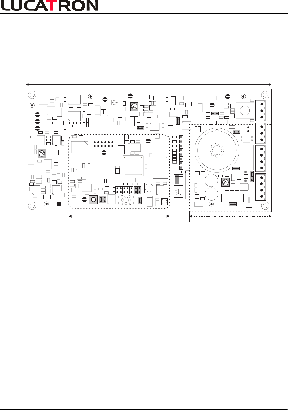
1. Basic Description, Receiver Electronics
The URB-100 receiver board consists of a:
- Analog Part
- Digital Part
- Power / Alarm Part
Analog Part
Digital Part Power / Alarm Part
+
+-
+
GNDP3/RF
P4/
RF
GND
GNDGND
GND
P1/RF
P9
P2
P7
P6
R224
P5
P11
R112
P10
P8
S3
S2
ON OFF
X18
R426
DSP
J10
J4
J9
J8
J1
J3
J2
J5
J7
IN NC IN
OUT NC OUT
Power (X1) Relay (X3) Light (X4) Antenna (X2)
X6
Fuse
S1
X7
X5
(+ +) (- -)
J6
WD R
RF-Gain
BeatBeatBeat
Beat
Beatnote
Gain
LF
Video
Video
LF
Sync
Mod
Volume
0
4
6
2
8
1
RLY NC NO GND
Receiver Board
1.1. Analog Part
The first input stage amplifies the received RF signal. If this signal is too large, the gain of the first
input stage can be reduced using jumper J4 (Narrow or Wide position).
The next stage is a band-pass filter having a frequency range between 7.2 to 9.2
MHz. If necessary,
the gain of the RF amplifier following the band-pass filter can be changed with potentiometer R112
(RF-Gain). An AGC is not built in, this gives a controlled RF amplification. The amplitude of the tag
signal is pre-regulated by a fixed resistor. The DSP synchronization is done through "air", that is
extracted from the received transmitter signal. A beat note circuit is implemented. This circuit is
inhibiting spikes, radio transmitters and other signals with a very high Q factor.
1.2. Digital Part
The analog tag signal is A
/
D converted and sampled. The DSP (40
MIPS) filters the demodulated LF
signal and stores the result in a memory. It processes this data and if all alarm criteria are met, it
triggers an alarm.
DIL and rotary octal switches allow adjusting the software parameters and test positions.
BASICS

URB-100 Tuning Guide
LUCATRON AG
CH-8606 Greifensee, Switzerland Version 2 Page 4
1.3. Power
/
Alarm Part
Power is supplied to the receiver electronics by applying 20-24
VDC or 18-20
VAC to the power
supply/power filter part. The integrated filter is used to reduce any interference picked up on the
incoming line from the power supply.
An audible alarm (buzzer) is mounted on the filter part. Outputs for the antenna lamp and an external
alarm are provided.
The volume of the buzzer is adjustable with the Volume potentiometer (R426). A jumper (J10) on the
filter part allows setting the buzzer for continuous or intermittent (optional) tone. The duration of the
audible alarm is about 2 seconds. The duration of the alarm light is about 10 seconds.
2. Description of Features
2.1. Manually Adjustable RF Gain
RF gain needs to be adjusted depending on the antenna type and the aisle width. In tuning mode
S2=7 the RF level is shown on the scope and can be adjusted with (RF Gain) R112. With jumper J4
(RF attenuator) an additional attenuation of 10
dB can be selected.
2.2. Air Synchronization
The sweep information is extracted by a PLL, which is factory adjusted.
2.3. Synchronous Demodulator
The synchronous demodulator has a wide linear input range of 50
mVpp to 600
mVpp and high
conversion gain. If the maximum level is exceeded, then the receiver is muted and the Inhibit
(LED-4) status is on.
2.4. Beat Note Filter
The beat note filter detects carrier signals that are crossing (beating) the system sweep. If the signal
is too strong then DSP blanks it out. The sensitivity is adjustable with (Beat Note Gain) R224. The
beat note filter is active when LED-5 is flashing.
2.5. Software Click Filter with Adaptive Slope
Normally a demodulated tag signal is smooth. When the slewrate of a signal is too fast, this is an
indication of induced noise and will be blanked out by the DSP. Some Hi-Q tags can trigger the filter.
In that case it can be switched off with S3-5. Click filtering is active when LED-6 is flashing.
2.6. Software Spike Blanker
The spike blanker counts the number of samples that are above a certain level. The level is about
50% of the actual alarm threshold. When a preset limit of counts is exceeded then the blocking acts,
thus preventing false alarms in a noisy environment. The blanking is visible on LED-7.
FEATURES

URB-100 Tuning Guide
LUCATRON AG
CH-8606 Greifensee, Switzerland Version 2 Page 5
2.7. Accept Counter
The accept counter counts the number of consecutive sweeps detecting a tag. If the limit is reached in
both sweeps, then an alarm is generated. The default is 24 sweeps, which gives approximated
300
ms response time. A faster response time can be selected with S3-3.
2.8. Threshold Calculation
The threshold level is based on the signals plus noise averaged over the detection sweep. Under
normal condition this would prevent from triggering an alarm because the threshold rises with
increasing tag signal. The threshold is therefore delayed by approx. 1.5 seconds. This is roughly the
time you have to trigger the alarm at full sensitivity. With the same time delay the system is back to
full sensitivity again.
2.9. Alarm Threshold Margin Settings
With switch S3-1 and S3-2 it is possible to adjust the alarm margin in 4 steps of 3
dB. The actual
margin (peak signal to alarm threshold) is displayed on the LED Levelmeter. The actual alarm
threshold level can be observed on the scope output.
FEATURES

URB-100 Tuning Guide
LUCATRON AG
CH-8606 Greifensee, Switzerland Version 2 Page 6
3. Tuning
3.1. Philosophy
A system will be put into operation as follows:
- First the TX (all) has to be prepared and then tuned.
- Second the RX (s) has to be prepared and then tuned.
- Third set the alarm conditions and make a final check. After this procedure the system is
ready for operation.
If an already installed system needs to be checked, the Quick Check procedure may give a first
indication about the system status.
An overview about the expert tuning and/or quick check procedures is given in a flow chart.
3.2. Recommended Tools
The following instruments are necessary for tuning:
- Multimeter
- Battery-powered oscilloscope with two channels (minimum 20
MHz bandwidth).
- 10:1 oscilloscope probes
- Recommended: SMB cable (female
/
female, 1meter
/
3 feet) plus BNC
/
SMB adapter
(male
/
male). Radiall P
/
N R285215 and R191209.
- Recommended: Sweep Span Meter (e.g. XRST-1 crosspoint.nl) or equal. The SSM
displays the minimum, maximum, center and the sweep frequency of a swept RF signal.
3.3. Receiver Preparatory Steps
3.3.1. Preparation
• Remove power from the RX board by removing the PWR connector at socket X2.
• Verify the default jumper J1 to J9 settings (J4 and J6 are under the shield). See table and
layout.
Jumper (J1) (J2) (J3) J4 (J5) (J6/WD) (J7) J8 J9 J10
Setting IN IN IN OUT IN IN IN IN EXT IN
Remark ( ) = Factory use only Wide/
Narrow ()=Factory Sound
ON/OFF
Remote
Alarm Sound
RX Default Jumper Settings
TUNING

URB-100 Tuning Guide
LUCATRON AG
CH-8606 Greifensee, Switzerland Version 2 Page 7
• Verify that the antenna wires are connected to connector X2. The antenna wires must be
connected to terminal 1 and 3.
+
+-
+
GNDP3/RF
P4/
RF
GND
GNDGND
GND
P1/RF
P9
P2
P7
P6
R224
P5
P11
R112
P10
P8
S3
S2
ON OFF
X18
R426
DSP
J10
J4
J9
J8
J1
J3
J2
J5
J7
IN NC IN
OUT NC OUT
Power (X1) Relay (X3) Light (X4) Antenna (X2)
X6
Fuse
S1
X7
X5
(+ +) (- -)
J6
WD R
RF-Gain
BeatBeatBeat
Beat
Beatnote
Gain
LF
Video
Video
LF
Sync
Mod
Volume
0
4
6
2
8
1
RLY NC NO GND
RX Default Jumper Settings Layout
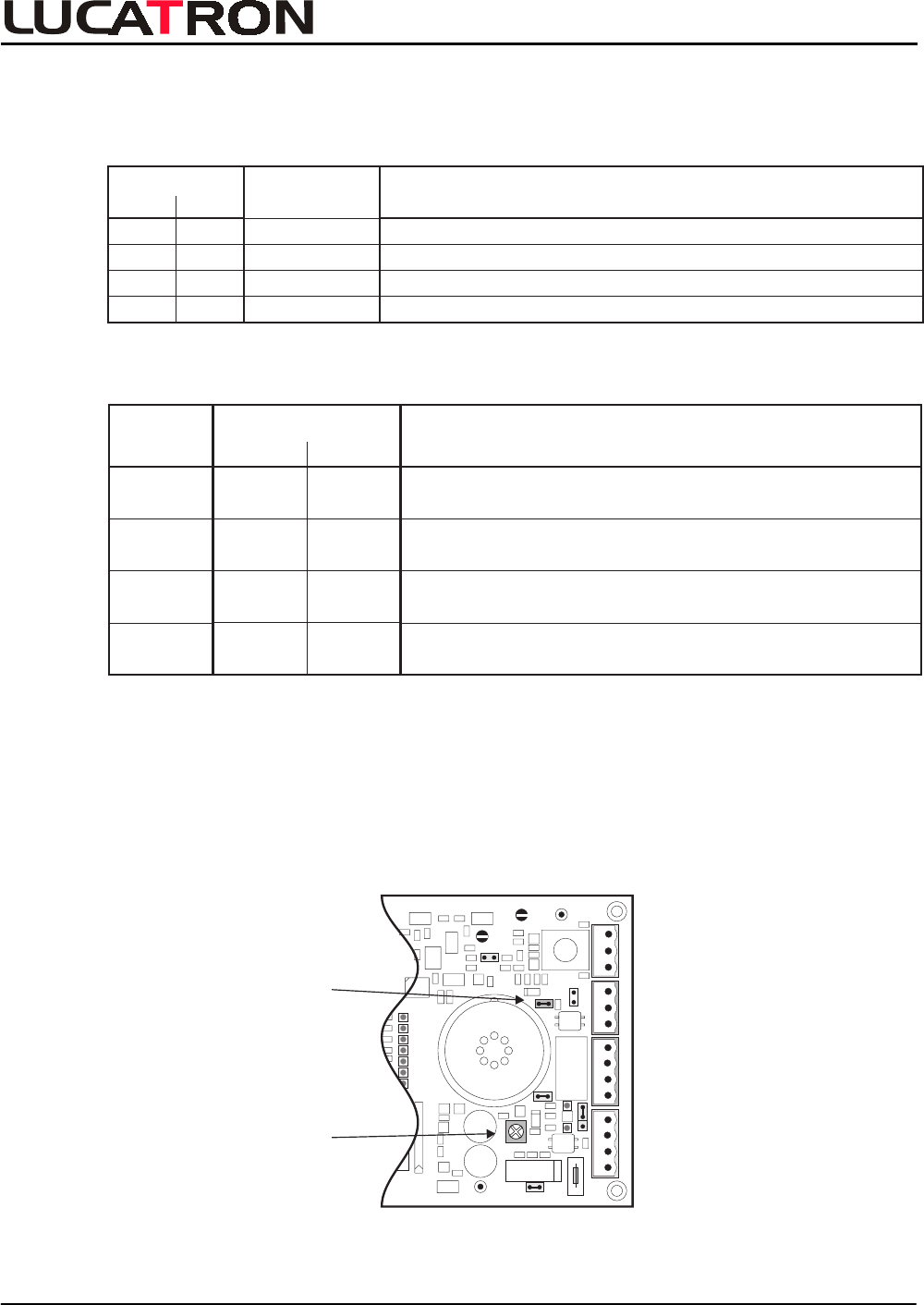
• Set the Rotary switch (S2) to the 0 position and all six (6) DIL (S3) switches to the ON
position. These are the default settings.
0
4
6
2
8
Rotary
Switch
S2
DIL
S3
ON OFF
S3-6
S3-5
S3-4
S3-3
S3-2
S3-1
Rotary and DIL Switch Default Settings
TUNING
URB-100 Tuning Guide
LUCATRON AG
CH-8606 Greifensee, Switzerland Version 2 Page 8
3.4. Receiver Tuning
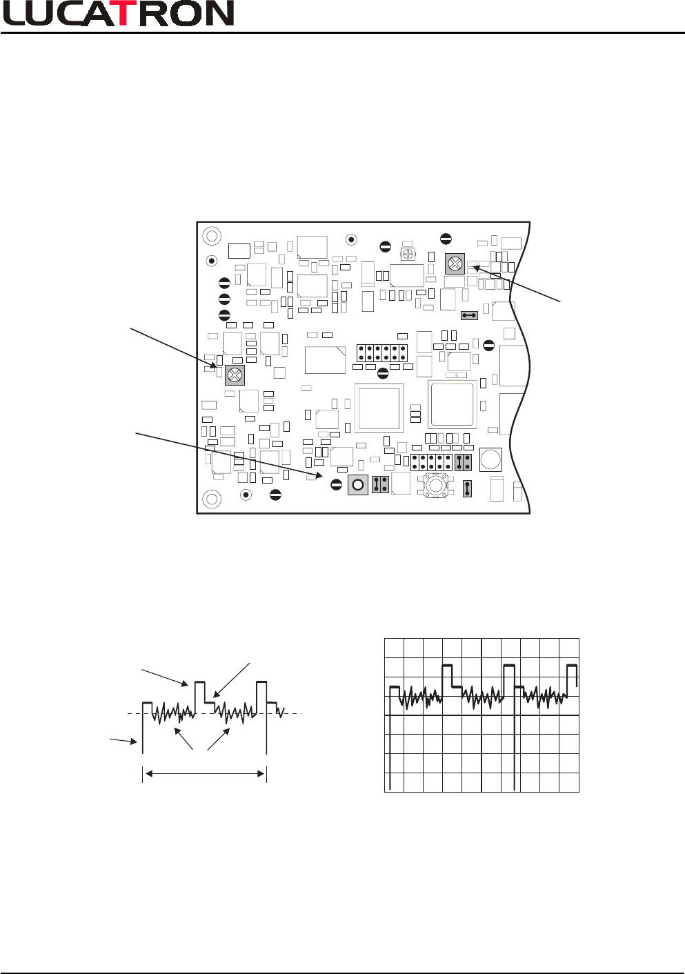
3.4.1. RF Gain Adjustment
• Apply power to the RX board (X1 Power connector).
• Turn the Beat Note-Gain (R224) potentiometer counter clockwise to the minimum position.
• Turn the RF-Gain (R112) potentiometer counter clockwise to the minimum position.
• Connect the oscilloscope probe (100
mVpp
/
Div.) to P11-Video or X18-Video.
GND
GND
GND
P1/RF
P9
P2
P7
P6
R224
P5
P11
R112
P10
P8
X18
DSP
J3
J5
J7
S1
X7
X5
J6
WD R
RF-Gain
BeatBeatBeat
Beat
Beatnote
Gain
LF
Video
Video
LF
Sync
Mod
Beatnote Gain
Potentiometer
Video Signal
P11 or X18
RF - Gain
Potentiometer
RF Adjustment Controls
• Set the sweep time to 2
ms
/
Div. Synchronize to the negative pulse. The figures below
explain the video signal in detail.
1 Sweep
Sync
Pulse
Actual Noise
Alarm
Threshold
Level
Noise Indicator
Level
Video Signal without a Tag Signal
RX TUNING

URB-100 Tuning Guide
LUCATRON AG
CH-8606 Greifensee, Switzerland Version 2 Page 9
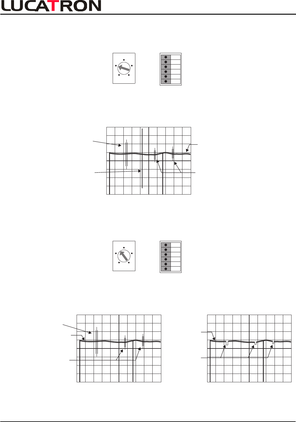
• Set Rotary switch to position 7 (RF-Gain Adjustment). Let all DIL switches in the ON
position.
0
4
6
2
8
Rotary
Switch
S2
DIL
S3
ON OFF
S3-6
S3-5
S3-4
S3-3
S3-2
S3-1
• Check the signal. The signal form could look like the figure below.
Caution: The lower part of the signal form can vary, depending on the antenna
impedance and
/
or the environment.
RF-Signal
• Turn the RF-Gain potentiometer until the signal looks similar to the figure below.
Maximum
Sensitivity
Less
Sensitivity
Perfect RF-Signal Adjustment Wrong (system blocked
Rule: Nothing of the curved part of the signal should be higher than the flat part of it.
However its top should be as high as possible.
If the signal is not adjustable, following the given rule (e.g. small aisle width):
- Insert J4 (Wide / Narrow).
- Reduce TX output power.
RX TUNING
URB-100 Tuning Guide
LUCATRON AG
CH-8606 Greifensee, Switzerland Version 2 Page 10
3.4.2. Beat Note Adjustment
• Set Rotary switch to position 3 (LF signal before correlation).
0
4
6
2
8
Rotary
Switch
S2
DIL
S3
ON OFF
S3-6
S3-5
S3-4
S3-3
S3-2
S3-1
• Check the signals on the figure below.
Caution: If high deactivator signal amplitudes are present (like in the figure below). The
deactivator(s) must be switched off for the following Beat Note adjustment.
Radio Signal
Deactivator
Signal Other System
(Moving)
Noisy Signal
Different Signal Sources
• Set Rotary switch to position 4 (Beat Noted, LF signal).
0
4
6
2
8
Rotary
Switch
S2
DIL
S3
ON OFF
S3-6
S3-5
S3-4
S3-3
S3-2
S3-1
• Turn the Beat Note potentiometer until the signal looks similar to the figure below.
Caution: If the potentiometer is turned too much clockwise, the sensitivity will be reduced
until the system is blocked.
Radio Signal
Other System
(Moving)
Noisy Signal
Blanked
Areas
Noisy
Signal
Before Adjustment After Adjustment
RX TUNING
URB-100 Tuning Guide
LUCATRON AG
CH-8606 Greifensee, Switzerland Version 2 Page 11
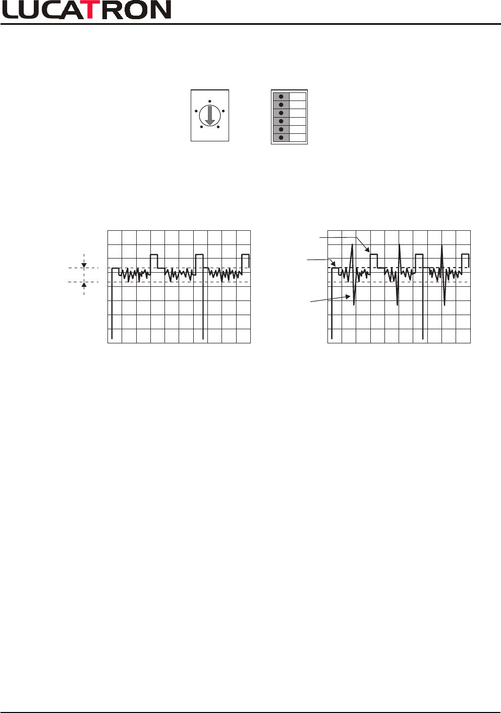
3.4.3. Signal
/
Noise Level Check
• Set Rotary switch to position 0 (Running
/
Default Mode).
0
4
6
2
8
Rotary
Switch
S2
DIL
S3
ON OFF
S3-6
S3-5
S3-4
S3-3
S3-2
S3-1
0
4
6
2
8
Rotary
Switch
S2
DIL
S3
ON OFF
S3-6
S3-5
S3-4
S3-3
S3-2
S3-1
• Check the level of the actual noise. It is normally in the range between 50 to 150
mVpp.
• Hold the reference tag or label in front carry position in to the system and check the signal
level: An alarm will be triggered if the tag signal exceeds the Alarm Threshold (which is
set by default 3 times the Noise Indicator Level).
100 mVpp
Noise
Tag
Signal
Alarm
Threshold
Noise
Indicator
Noise Tag Signal + Noise
If the Tag Signal level is much too high comparing to the alarm threshold:
- Set A
/
N Ratio to 4.5:1 (DIL switch S3-1 to the OFF position) or see DIL Switch
Table in chapter 3.4.4.
- Reduce the system sensitivity with the RF-Gain potentiometer, turn it counter
clockwise.
Caution: The Alarm Threshold is self-adapting.
RX TUNING
URB-100 Tuning Guide
LUCATRON AG
CH-8606 Greifensee, Switzerland Version 2 Page 12
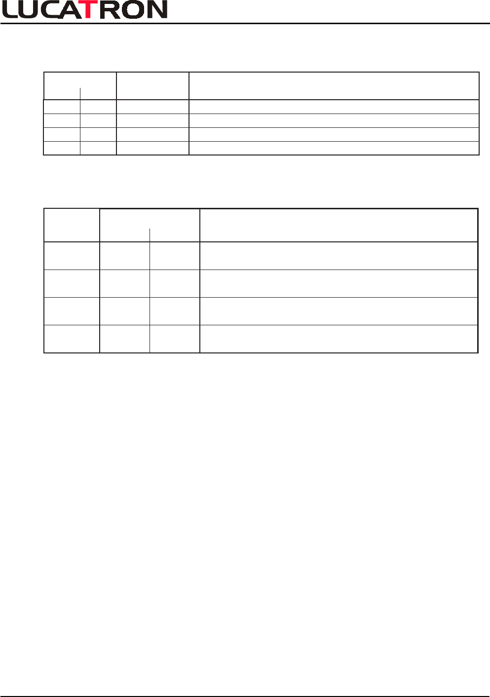
3.4.4. DIL Switch Settings
• The recommended (default) DIL switch (S3-1 to S3-6) settings are the ON position. For an
alternative setting see tables.
DIL Switch S3
S3-1 S3-2 Description
ON
A / N Ratio
Alarmthreshold to Noiselevel Ratio, for low signal Tag o r Label
A / N Ratio, for high signal Tag
OFF
ON
ON
OFF OFF
OFF
ON
3:1
4.5 : 1
6:1
7.5 : 1
A / N Ratio
A / N Ratio
DIL Switch S3-1 and S3-2 Table
S3-3
S3-6
24 8
Enable Disable
S3-5 Normal Alternate Baseband Filter: - Normal Baseband Filter
- Alternate BF, reduces low Q artefacts
Alarm Accept
Counter:
Position
ON (Default) OFF Description
DIL Switch
S3
- 24 Times, Alarm Conditions fulfilled
- 8 Times, Alarm Conditions fulfilled
S3-4 ---------- Not implemented yet
Click Filter: - Enable, Click Filter active
- Disable, Click Filter not active
DIL Switch S3-3 until S3-6 Table
3.5. Alarm Adjustments
• Set Volume potentiometer R426 to the desired level.
With Jumper J10 the sound can be changed from intermitted (default = IN) to
continuous (= OUT).
External Alarm Connector X3 (see Appendix).
8
+
+-
+
GNDP3/RF
P4/
RF
GND
R426
J10
J4
J9
J8
J1
IN NC IN
OUT NC OUT
Power (X1) Relay (X3) Light (X4) Antenna(X2)
X6
Fuse
(+ +) (- -)
Volume
RLY NC NO GND
Intermitted /
Continous
Volume
Sound Controls
RX TUNING

URB-100 Tuning Guide
LUCATRON AG
CH-8606 Greifensee, Switzerland Version 2 Page 13
3.6. Quick Check
3.6.1. Basics
For a Quick Check, the Rotary switch (0 to F9) can be turned to different Test positions. The LED
“Test” indicates that the Rotary switch is not anymore in the standard (0) position. The three yellow
Indicator LED’s are used as a Levelmeter. The Quick Check Procedure is no full replacement of the
real tuning as described in chapters 3.4 – 3.5. Especially the proper setting of the beat note level
needs to be done with the help of an oscilloscope.
3.6.2. RF-Gain Check
• Set Rotary switch to position 7 (RF-Gain Check / Adjustment). The Test LED is lit.
Let all DIL switches in their ON position.
0
4
6
2
8
Rotary
Switch
S2
DIL
S3
ON OFF
S3-6
S3-5
S3-4
S3-3
S3-2
S3-1
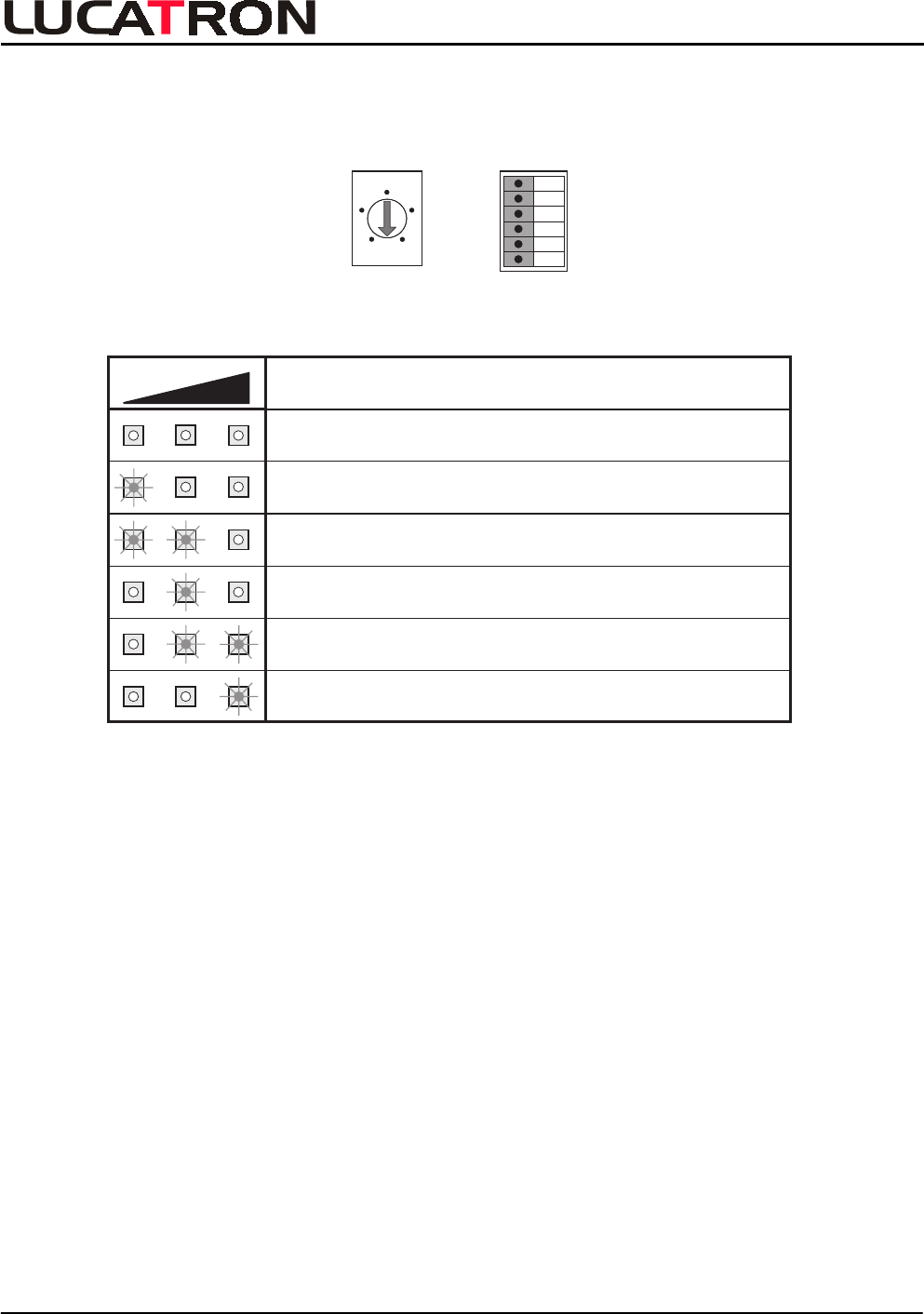
• Turn the RF-Gain potentiometer R112 until only the Center LED of the Levelmeter is ON.
Note: Before start turn the RF-Gain potentiometer fully counter clockwise.
Levelmeter
Clickfilter
Beatnote
Inhibit
Test
Caddy-
blanker
ON ON
RF-Gain Check
/
Adjustment
Levelmeter Action
Turn from fully counter clockwise
until a yellow LED goes on.
Turn clockwise to find the yellow
Center LED.
Turn slowly clockwise until only
the yellow Center LED is on.
OK, Perfect
Turn slowly counter clockwise until
the yellow Center LED is on.
Turn counter clockwise to find
the yellow Center LED.
Step by Step RF-Gain Adjustment
Remark: If the RF-Gain is much too high, the third of the Levelmeter and the Inhibit LED
will be on.
Q
UICK CHEC
K

URB-100 Tuning Guide
LUCATRON AG
CH-8606 Greifensee, Switzerland Version 2 Page 14
3.6.3. Beat Note Check
Note: The Beat Note Adjustment can’t be done in a Quick Mode, for a correct adjustment and to
find indications about the source of problems see chapter 3.4.2.
• Set Rotary switch to position 0 (Running
/
Default Mode).
0
4
6
2
8
Rotary
Switch
S2
DIL
S3
ON OFF
S3-6
S3-5
S3-4
S3-3
S3-2
S3-1
0
4
6
2
8
Rotary
Switch
S2
DIL
S3
ON OFF
S3-6
S3-5
S3-4
S3-3
S3-2
S3-1
• Check if the Beat Note LED is:
- OFF, no disturbing signal is around or the circuit is inactive.
- Sporadic flashing, the Beat Note is inhibiting some signals (no sensitivity loss).
- Quick constant flashing, wrong adjustment or to much disturbance signals
(sensitivity loss).
- Constant ON, System is blocked.
Levelmeter
Clickfilter
Beatnote
Inhibit
Test
Caddy-
blanker
Flashing
Beat Note Check
Q
UICK CHEC
K
URB-100 Tuning Guide
LUCATRON AG
CH-8606 Greifensee, Switzerland Version 2 Page 15
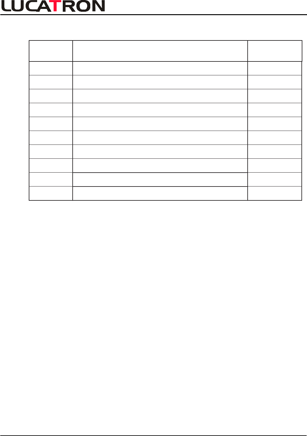
3.6.4. Signal
/
Noise Check
• Set Rotary switch to position 0 (Running
/
Default Mode).
0
4
6
2
8
Rotary
Switch
S2
DIL
S3
ON OFF
S3-6
S3-5
S3-4
S3-3
S3-2
S3-1
0
4
6
2
8
Rotary
Switch
S2
DIL
S3
ON OFF
S3-6
S3-5
S3-4
S3-3
S3-2
S3-1
• Check the Signal Noise Level according to the table below.
Levelmeter Noise / Explanation
< 100 mVpp
Ideal (Wide Exit)
100 - 150 mVpp
Typical / Good (Wide Exit)
150 - 200 mVpp
Typical / Acceptable (Not recommended for wide exit system)
200 - 250 mVpp
Acceptable (Not recommended for wide exit system)
250 - 300 mVpp
Worst case (Not recommended for wide exit system)
300 - mVpp
¥
Unacceptable (Not recommended for wide exit system)
Signal
/
Noise Level Table
Hint: - In a good installation all three yellow LED’s are OFF or the first LED is
sometimes flickering.
- The worst acceptable case for a wide exit installation using series 400 labels is:
- First LED continuous ON and the second LED flickering.
QUICK CHEC
K

URB-100 Tuning Guide
LUCATRON AG
CH-8606 Greifensee, Switzerland Version 2 Page 16
4. Appendix
4.1. Technical Specifications
Receiver Board URB-100
Electronics
RF Frequency Range 7.2 – 9.2
MHz
Synchronization Frequency Range 78 – 86
Hz (82
Hz default)
RF Signal Input Range (Antenna) 10 – 70
mVpp (30 –210
mVpp with attenuator)
Antenna Input Impedance 200
Ohm
DSP Performance 40
MIPS
RF Gain Adjustable
Beat Note Adjustable
Switches
S1 Push Button (Factory)
S2 Rotary (Check and Test Purposes)
S3 DIL (System Parameters)
Status Indicators
Power Green LED
Alarm, Test, Beat, Click, Spike, Inhibit Red LED’s
Levelmeter 3 yellow LED’s
Alarm Controls
Buzzer Volume, adjustable to maximum 95
dB
Sound Time, approx. 2 seconds
Light Light Time, approx. 10 seconds
Connectors
X1 Power (DC or AC)
X2 Antenna (Antenna Matching Board)
X3 External Alarm
X4 Alarm Lamp of Antenna
X5 JTAG (Factory use only)
X6 Optional Buzzer
X7 Serial
X18 Video
Power Voltage Range
AC Input 18 – 20
VAC at 150
mA
DC Input 20 – 24
VDC
Alarm Light Consumption max. 500
mA
Fuse 800
mA, quick - acting F
APPENDIX
URB-100 Tuning Guide
LUCATRON AG
CH-8606 Greifensee, Switzerland Version 2 Page 17
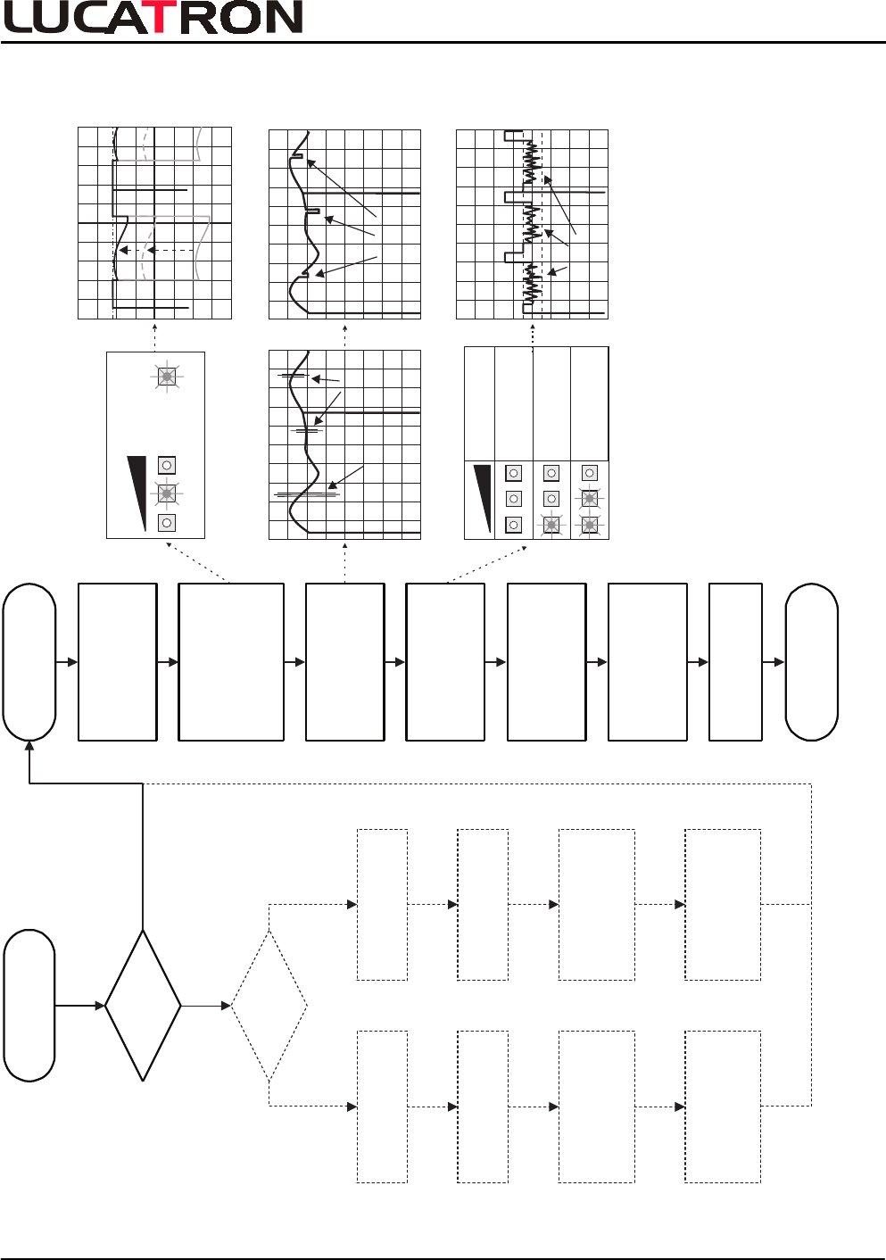
4.2. Tuning Flowchart
Start
Sytem Tuning
Is
TX (T3600)
tuned
Start
RX Tuning
Preparation
1. Rotary = 0
2. Beat-Note to min.
3. RF-Gain to min.
RF Adjustment
1. Rotary = 7
2. RF-Gain = Center
yellow LED ON
or Osci (Manual 3.4.1)
Beat-Note Adjustment
1. Deactivator(s) OFF
2. Rotary = 4
3. Manual 3.4.2
Signal Noise Check
1. Rotary = 0
2. Max. 1 to 2 yel.LED
DIL Switch Settings
1. DIL Switch Table
Manual 3.4.4
Alarm Controls
1. Volume
System Check
End
Master
J1=M / J5=M
J2/3/19/20
= “QS4000”
Output 25Vpp
TP4 or TP5 to GND
RF-LVL (R52)
Check/Adjust
Freq. 7.4-9.0MHz
C-Freq. R50/Dev. R49
J1=S / J5=FS
J2/3/19/20
= “QS4000”
Output 25Vpp
TP4 or TP5 to GND
RF-LVL (R52)
Check
Freq. 7.4-9.0MHz
at Master Box
No Yes
No
Yes
Tes t
ON ON
Levelmeter
Radio
Signal
Other
System
(Moving) Blanked Areas
Noise
100mVpp
Levelmeter
< 100 mVpp
Ideal (Wide Exit)
100 - 150 mVpp
Typ./Good (W. Exit)
150 - 200 mVpp
Typ./Ac.(Less Sen.)
Noise/Expanation
APPENDIX
URB-100 Tuning Guide
LUCATRON AG
CH-8606 Greifensee, Switzerland Version 2 Page 18
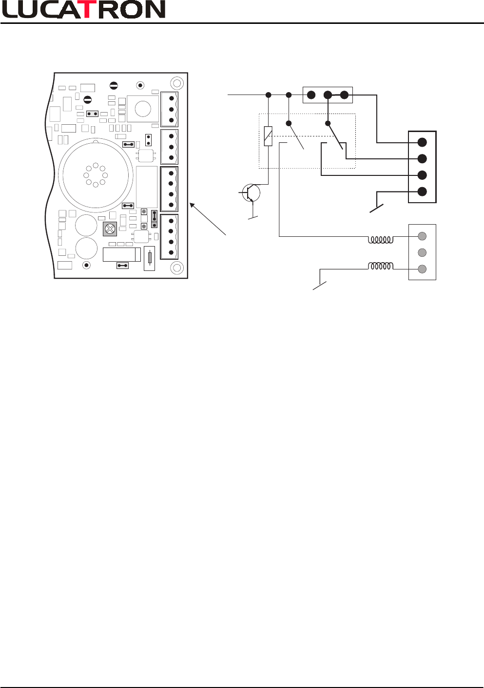
4.3. X3 Connector Layout (External Alarm Unit)
RLY = Common
NC = Normally Closed
NO = Normally Open
GND = Ground
+
+-
+
GNDP3/RF
P4/
RF
GND
R426
J10
J4
J9
J8
J1
IN NC IN
OUT NC OUT
Power (X1) Relay (X3) Light (X4) Antenna(X2)
X6
Fuse
(+ +) (- -)
Volume
RLY NC NO GND
EXTINT
Relay
+24 VDC/INT
max. 50mA
1RLY
NC
NO
GND
X3
J9
1
OUT
OUT
X4
Ant.
Light
X3 Connector Layout
Caution: If the internal 24
VDC is used, an additional DC Filter must be mounted into the external
lines. The DC Filter must be positioned directly by the X3 connector to protect the RX
board from external disturbance.
Relay data:
Contact Ratings:
Max. switching voltage 48VAC or 48VDC
Max. switching current 1A
Warning:
Never connect 230 / 110 Volt to connector X3. Dangerous voltage, capable of causing death.
APPENDIX
URB-100 Tuning Guide
LUCATRON AG
CH-8606 Greifensee, Switzerland Version 2 Page 19
4.4. DIL Switch Settings
DIL Switch S3
S3-1 S3-2 Description
ON
A / N Ratio
Alarmthreshold to Noiselevel Ratio, for low signal Tag o r Label
A / N Ratio, for high signal Tag
OFF
ON
ON
OFF OFF
OFF
ON
3:1
4.5 : 1
6:1
7.5 : 1
A / N Ratio
A / N Ratio
DIL Switch Table
S3-3
S3-6
24 8
Enable Disable
S3-5 Normal Alternate Baseband Filter: - Normal Baseband Filter
- Alternate BF, reduces low Q artefacts
Alarm Accept
Counter:
Position
ON (Default) OFF Description
DIL Switch
S3
- 24 Times, Alarm Conditions fulfilled
- 8 Times, Alarm Conditions fulfilled
S3-4 ---------- Not implemented yet
Click Filter: - Enable, Click Filter active
- Disable, Click Filter not active
DIL Switch Table
APPENDIX
URB-100 Tuning Guide
LUCATRON AG
CH-8606 Greifensee, Switzerland Version 2 Page 20
4.5. Rotary Switch Settings
Rotary Switch
S2 Settings
1+S1
2
3
4
5
6
7
8
Running / Default Mode (default position)
LF signal equal pos.3, with additional beat note blanking
Not used (factory only)
Temporarily blocked Alarm Threshold (for tests only)
RF-Gain Adjustment
Default
Check
Check
Factory
Test
Factory
Not used (factory only)
LF signal only (without alarm threshold)
LF signal before correlator
LF signal equal pos.4, with additional click filter blanking
LF signal equal pos.5, with additional correlator filter
9
0
Adjustment/Check
Adjustment
Check
Check
Check
Description used for
Rotary Switch Table
APPENDI
X
URB-100 Tuning Guide
LUCATRON AG
CH-8606 Greifensee, Switzerland Version 2 Page 21
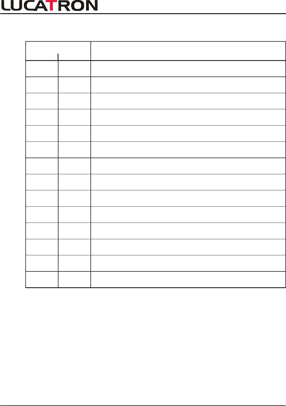
4.6. Test Points
Test Points
Test Point Labeled Description
P1
P2
P3
P4
P5
P6
P7
P8
P9
P10
P11
X18
X5
RF
LF
RF
RF
LF
Beat
Beat
FS
MOD
Sync
Video
Video
JTAG
RF Signal before Demodulator
LF Signal, a demodulated RF Signal before the Linear Phase Filter
RF Signal after the Antenna Input Transformator
Beat Note
Beat Note, Blank Signal
Frame Sync (DSP)
Modulator
Synchronisation
Factory use only
RF Signal before Bandpass Filter
RF Signal after Bandpass Filter
Video Signal, Sync Signal included
Video Signal, Sync Signal included
X7 Serial Factory use only
Test Points Table
Appendix
URB-100 Tuning Guide
LUCATRON AG
CH-8606 Greifensee, Switzerland Version 2 Page 22
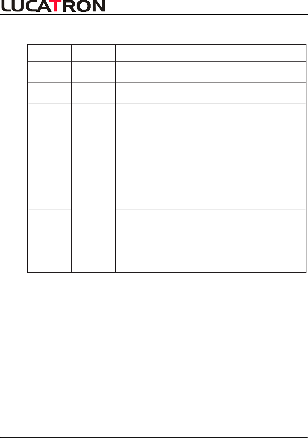
4.7. Jumper Settings
Jumper Settings Meaning
IN*
OUT
(J1)
Narrow = Pre-Amplifier gain reduction
Wide =No gain reduction
(J2) IN*
OUT
(J3)
J4
(J5)
(J6)
(J7)
J8
J9
IN*
OUT
IN
OUT*
IN*
OUT
IN*(WD)
OUT(R)
IN*
OUT
IN*(EXT)
OUT(INT)
Connects the +24 VDC to the voltage regulators
Factory use only
unregulated
Connects the +12 VDC to the RF circuits
Factory use only
regulated
Connects the +5 VDC to the digital circuits
Factory use only
regulated
Connects the regulated +12 VDC to the LF circuits
Factory use only
Watchdog active
Reset, factory use only
Sychronization for the DSP
Factory use only
Continuous alarm sound
Intermittent alarm sound
External alarm (X3) supplied by external voltage supply
External alarm (X3) supplied by internal +24 VDC, max. 50 mA
IN*(1-2)
OUT(3-4)
Sound active (ON)
Sound inactive (OFF)
J10 IN*
OUT
Jumper Settings Table
Agenda:
- ( ) For factory use only
- * Default setting
A
pp
endi
x
URB-100 Tuning Guide
LUCATRON AG
CH-8606 Greifensee, Switzerland Version 2 Page 23
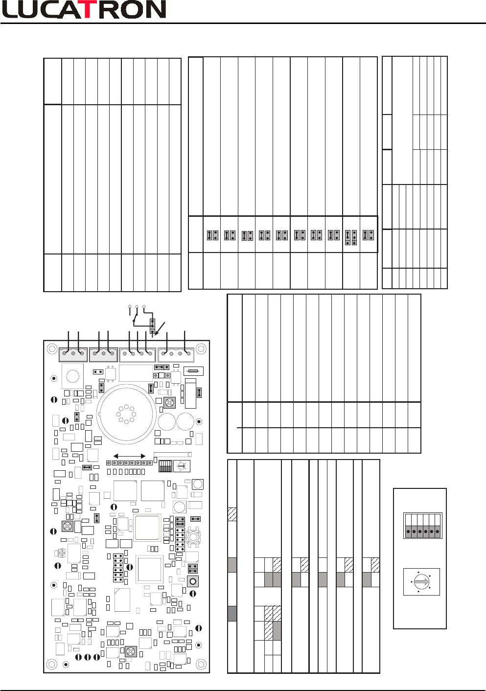
4.8. Compressed Overview
T
est Points
Test Point Labeled Description
P1
P2
P3
P4
P5
P6
P7
P8
P9
P10
P11
X18
X5
RF
LF
RF
RF
LF
Beat
Beat
FS
MOD
Sync
V
ideo
V
ideo
JT
AG
RF Signal before Demodulator
LF Signal, a demodulated RF Signal
before the Linear Phase Filter
RF Signal after the Antenna Input Transform.
Beat Note
Beat Note, Blank Signal
Frame Sync (DSP)
Modulator
Synchronisation
Factoryuse only
RF Signal before Bandpass Filter
RF Signal after Bandpass Filter
V
ideo Signal, Sync Signal included
V
ideo Signal, Sync Signal included
X7 Serial Factory use only
1
2
3
4
5
6
7
8
LED
Green
Green
Green
Red
Red
Red
Red
Red
Color if active
Function
OFF ON Flashing
VU Meter
VU Meter
VU Meter
Inhibit
Beatnote
Clickfilter
Caddy-Blanker
Testmode
RF high
-----
-----
-----
Testmode
Normal
Normal
Normal
Normal
DSP failure
Beatnote active
Clickfilter active
Caddy-Blanker active
Normal
See table "RX Tuning Guide"
0
4
6
2
8
Rotary
Switch
S2
DIL
S3
ON OFF
S3-6
S3-5
S3-4
S3-3
S3-2
S3-1
DILSwitchS3 =ON x =de fa ult =OF F
4.5:1 7. 5:1 3:1 6:1
S3-1
x
S3-2
x
S3-3 Alarm Accept Co unte r x24 ti mes
8times
S3-4 x
S3-5 x
S3-6 x
Disable (ina ctive)
Alte rn ate, re duces l ow Q Arte fact s
Normal
not i mpl emente d yet
Baseband Fi lt er (BF)
Click Filter
Al armth resho ld to No i slev el Ratio
3:1 for Lowsignal T ag or Lab el.
6:1 for Highsig nal Tag or improve d
Phantom Alarm Prevent ion
Ratio
Enab le (a ct ive)
Jumper Settings Meaning
(J1)
Narrow = Pre-Amplifier gain reduction
Wide
=
No gain reduction
(J2)
(J3)
J4
(J5)
(J6)
(J7)
J8
J9
Connects the +24 VDC to the voltage regulators
Factory use only
unregulated
Connects the +12 VDC to the RF circuits
Factory use only
regulated
Connects the +5 VDC to the digital circuits
Factory use only
regulated
Connects the regulated +12 VDC to the LF circuits
Factory use only
WD Watchdog active
Reset, factory use only
Sychronization for the DSP
Factory use only
(spezial Option)
External alarm (X3) supplied by external voltage supply
External alarm (X3) supplied by internal +24 VDC, max. 50 mA
Sound active (ON)
Sound inactive (OFF)
J10
(default)
(default)
(default)
(default)
(default)
(default)
(default)
(default)
(default)
(default)
R
(spezial Option)
Rotary Switch
S2 Settings
1+S1
2
3
4
5
6
7
8
Running / Default Mode (default position)
LF signal equal pos.3, with additional beat note blanking
Not used (factory only)
Temporarily blocked Alarm Threshold (for tests only)
RF-Gain Adjustment
Default
Check
Check
Factory
Test
Factory
Not used (factory only)
LF signal only (without alarm threshold)
LF signal before correlator
LF signal equal pos.4, with additional click filter blanking
LF signal equal pos.5, with additional correlator filter
9
0
Adjustment/Check
Adjustment
Check
Check
Check
Description used for
RLY
+
+
-
+
GND
P3
P4
GND
GND
GND
GND
P1
P9
P2
P7
P6
R224
P5
P11
R112
P10
P8
S3
S2
ON OFF
X18
R426
DSP
J10
J4
J9
J8
J1
J3
J2
J5
J7
IN NC IN
OUT NC OUT
Power (X1) Relay (X3) Light (X4) Antenna
X6
Fuse
S1
X7
X5
(+ +) (- -)
J6
WD R
X2
3
2
1
0
4
6
2
8
1
RLY NC NO GND
NO
NC
Power
18 VAC
20-24VDC
Ant. Light
Ant. Wiring
+
GND
INT
+24VDC
J9
1
8
Appendix