SenTech EAS AQUILA User Manual Introduction
SenTech EAS Corporation Introduction
Contents
- 1. receiver manual
- 2. transmitter manual
transmitter manual
UTB-100 TX Tuning Guide
LUCATRON AG
CH-8606 Greifensee, Switzerland Version 1.0 Page 1
T
TX
X
T
Tu
un
ni
in
ng
g
G
Gu
ui
id
de
e
U
UT
TB
B-
-1
10
00
0
A
A

UTB-100 TX Tuning Guide
LUCATRON AG
CH-8606 Greifensee, Switzerland Version 1.0 Page 2
Table of Contents
Page
1. Introduction .................................................................................................................................3
1.1. Basic Description of the Transmitter Electronics...................................................................3
1.1.1. Digital Part................................................................................................................6
1.1.2. Analog Part...............................................................................................................6
1.1.3. Power Supply / Filter Part .........................................................................................6
1.2. Receiver Electronics.............................................................................................................6
2. UTB-100 Filter Concept...............................................................................................................7
3. Deactivator DAV-100 Synchronization.......................................................................................8
3.1. Cable Synchronization..........................................................................................................8
4. Opto TX Setup..............................................................................................................................9
4.1. One (1) Opto TX Output .......................................................................................................9
4.2. Two (2) Opto TX Output .......................................................................................................9
5. Installation Configurations .......................................................................................................10
6. Tuning ........................................................................................................................................12
6.1. Recommended Tools .........................................................................................................12
6.2. Preparation.........................................................................................................................12
6.3. Power On Adjustments.......................................................................................................14
7. Appendix....................................................................................................................................15
7.1. Compressed Overview .......................................................................................................15

UTB-100 TX Tuning Guide
LUCATRON AG
CH-8606 Greifensee, Switzerland Version 1.0 Page 3
1. Introduction
This manual describes the UTB-100 (Universal Transmitter Board) as well as the setup and tuning
procedures needed to put the UTB-100 and URB-100 electronics into operation. For details on the
receiver board, see the RX Tuning Guide.
1.1. Basic Description of the Transmitter Electronics
Each transmitter electronics is able to feed one LUCATRON antenna with a swept HF signal of
8.2
MHz. In order to avoid disturbances between the emitted HF signals, synchronization with other
transmitters must be guaranteed.
The standard version of the UTB-100 board allows the 82
Hz sinusoidal modulated 8.2
MHz HF carrier
signal to be:
−
−−
−
generated locally (oscillator circuit for master applications), or alternatively.
−
−−
−
to be regenerated from an optically received swept HF signal of another TX (opto
receiver for slave applications).
The bi-opto version of the UTB-100 additionally allows the onboard generated (master) or received-
and-then-regenerated- (slave)-swept HF-signal to be converted and optically transmitted in order to
synchronize additional transmitters.
The two opto transmitters used in the bi-opto version allow:
−
−−
−
a master transmitter to synchronize two other optically slaved (and possibly repeating)
transmitters.
−
−−
−
an optically slaved transmitter to be used as repeater to synchronize two other optically
slaved transmitters.
By using 3 bi-opto transmitter boards (TX) (one used as synchronization master and two as
synchronization repeaters) and 4 standard TX (as synchronization slaves), clusters of up to 7 TX may
be synchronized. This way up to 7 checkout or 14 exit-gates (in a row) may be configured without
need of a master rack.
Since the optically transmitted synchronization signal may be repeated only once, a master rack still
has to be used if more than seven transmitters have to be synchronized.
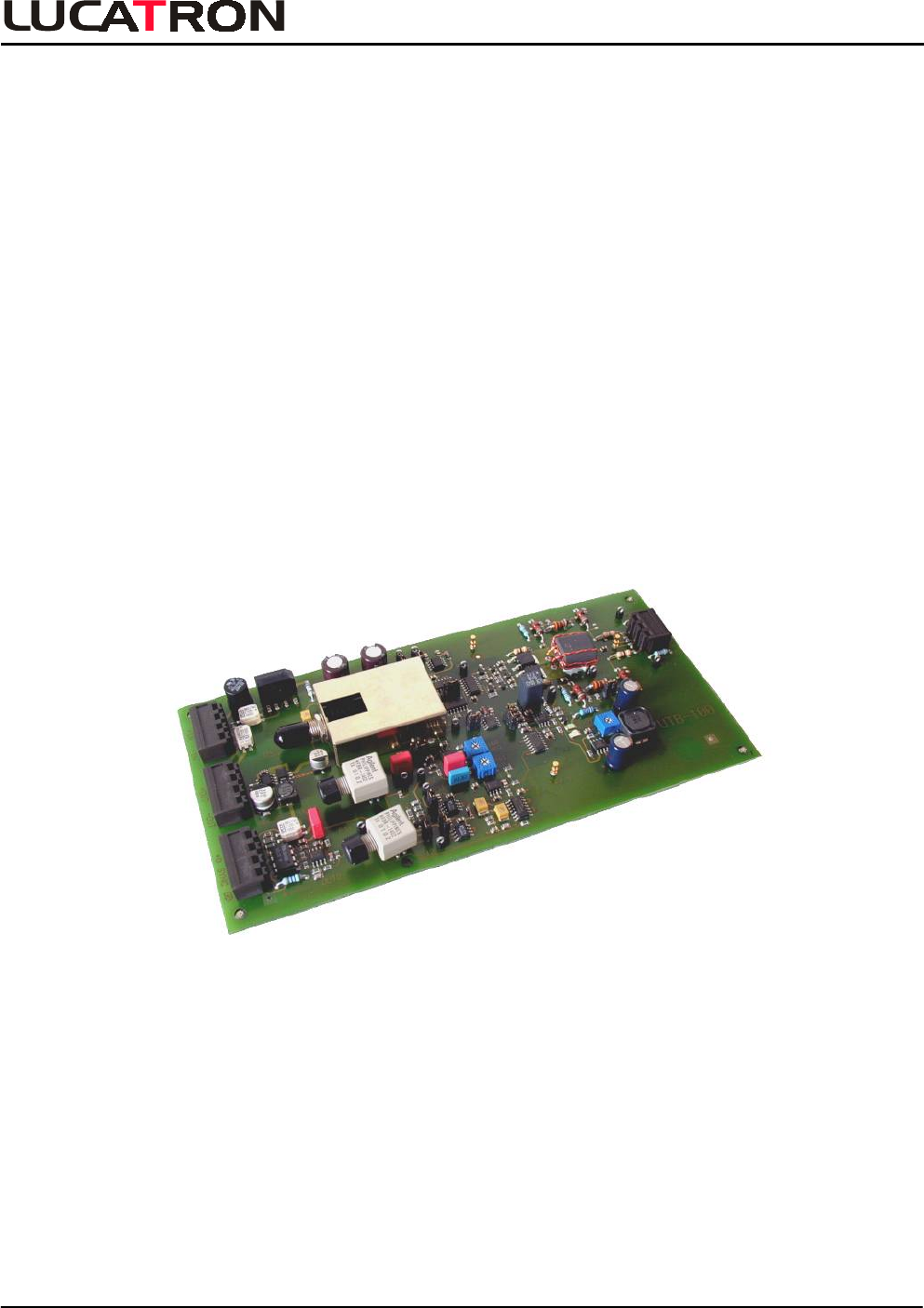
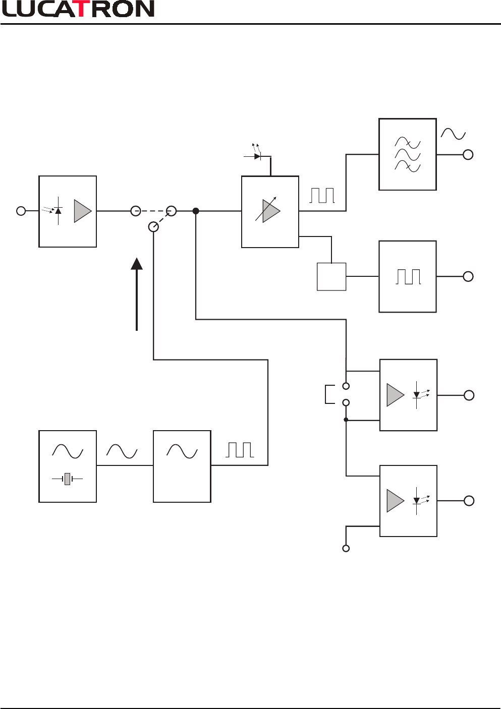
A block diagram and layout of the UTB-100 board are shown on the next 2 pages. The board consists
of a digital part, an analog part and a power supply / filter part.
The standard version of the UTB-100 is fully equipped with the exception of the two optional opto
transmitters. It can be used as a master-TX for small installations (single or dual gates equipped with
one TX only) or as slave-TX for all larger applications.
The bi-opto version of the UTB-100 board is almost identical to the standard version. The only
difference is that the two opto transmitters (IR-LED's) are already mounted. The bi-opto TX board can
be used as a master-TX in medium installations (2 to 7 TX) or as synchronization signal repeating
slave-TX for medium to very large installations.
INTRODUCTION
UTB-100 TX Tuning Guide
LUCATRON AG
CH-8606 Greifensee, Switzerland Version 1.0 Page 4
VCO
J4
82 Hz
+/- 3 Hz
8.2 MHz
Opto
Transmitter
Opto
Transmitter
Digital
Power
Amplifier
Current Limiter (TEMP)
Master
Opto
Receiver
J2 and J3
Opto
Output
TX1
Opto
Output
TX2
Antenna
Matching Circuit
X4
200 Ohm
J10
X3
Deact.
Sync
Output
De-
mod.
Sync Circuit
Opto
Input
+
TX Board Block Diagram
INTRODUCTION
UTB-100 TX Tuning Guide
LUCATRON AG
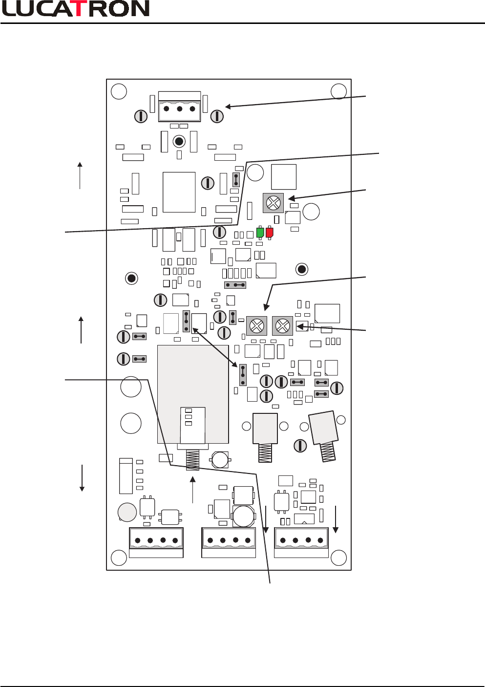
CH-8606 Greifensee, Switzerland Version 1.0 Page 5
Power
Supply
Filter
Part
Power
Input Connector
(22 VDC/18 VAC)
Power
Output Connector
Antenna
Connector
Digital
Part
Analog
Part
Amplitude
OUT1
OUT2
P14
P1 P2
P11
P9 P13
P3
P8
P10
P12
GND
GND
P6 P7
GND
P5
P4
R168
FREQ
R161
DEV
R147
LVL
J1
J4
J6
J2
J5 J9
J10 J8
J3
Power (X1)
(+ +) (- -)
Power (X2)
(+ +) (- -)
SYNC (X3)
D+ GND
IN GND IN
Antenna(X4)
IN
+ IN - IN + OUT - OUT
(+SYNC-)
SYNC OUT Deact.
J7
Opto1
(Optional)
Opto2
(Optional)
1
Master / Slave
1
ANTANT GND
TEMP
READY
Deviation
Frequency
UTB - 100
Fuse
Filter
Filter
630mA
1
T
TX Layout
INTRODUCTION
UTB-100 TX Tuning Guide
LUCATRON AG
CH-8606 Greifensee, Switzerland Version 1.0 Page 6
1.1.1. Digital Part
In master operation, the 82
Hz sinusoidal sweep is fed to the voltage controlled oscillator (VCO). The
VCO generates the swept and digitalized 8.2
MHz signal. This frequency modulated signal is digitally
amplified (FET power amplifier), filtered to get a clean analog output signal and finally radiated by the
antenna. lf the current exceeds the allowed limit (short circuits, wrong antenna etc.) the power
amplifier will shut slowly down, because it is temperature controlled. This action is indicated by a red
LED (overloaded = OFF).
In slave operation, the swept HF signal is optically received, converted and regenerated. It can then
be used to directly feed the power amplifier.
A set of jumpers (J2 and J3) is used to switch between master and slave operation. Jumper J4 is
used to select the desired sweep frequency.
lf the board is equipped with two opto transmitters (bi-opto TX board), the swept HF signal will be
automatically output (see section 4). This allows the synchronization of two additional transmitters.
1.1.2. Analog Part
Different antenna types can to be connected to the relevant output circuit (connector X4).
The TX-mounted matching circuits and harmonic suppression filters are optimized for use with
200 Ohm antennas.
The UTB-100 is not designed to drive other types of antennas. All equipment and system
guarantees will be lost and all field support will be charged if other types of antennas are
used without written approval of LUCATRON.
1.1.3. Power Supply / Filter Part
The UTB-100 can be powered (connector X1
/
IN) by DC as well as AC power supplies.
The integrated power line filters:
−
−−
−
suppress noise between the electronics and the power line and
−
−−
−
suppress conducted noise on the power line itself.
The filtered power is available at connector X2
/
OUT and can be used to feed other equipment
(TX, RX). For additional information, see section 2, UTB-100 Filter Concept.
1.2. Receiver Electronics
For detailed information on the receiver, see RX Tuning Guide.
INTRODUCTION
UTB-100 TX Tuning Guide
LUCATRON AG
CH-8606 Greifensee, Switzerland Version 1.0 Page 7
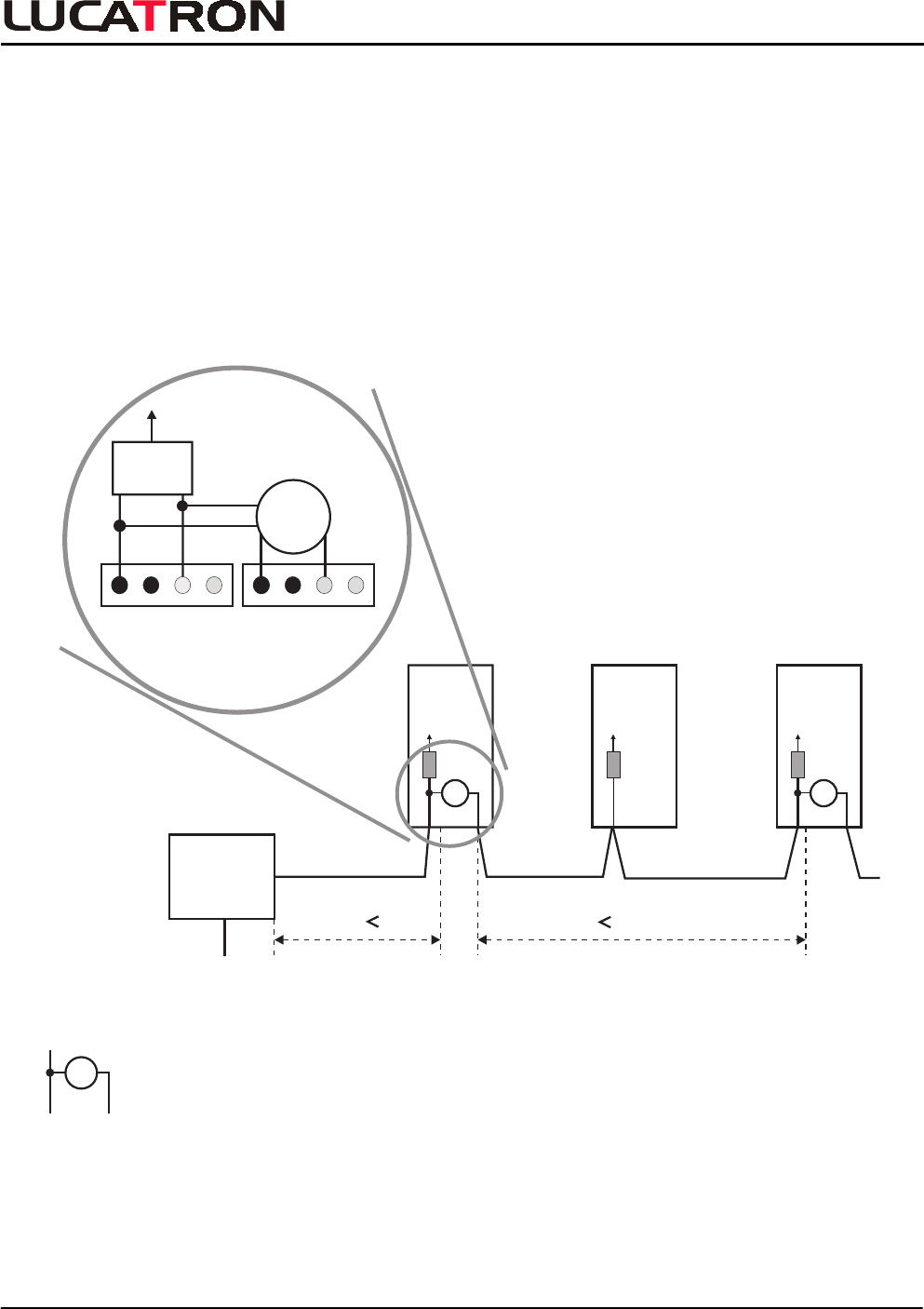
2. UTB-100 Filter Concept
False alarms due to conducted noise on the power lines can be avoided if the power lines are filtered
every 4 to 6 meters.
If UTB-100’s are used, this is done automatically and the power line between the transmitters is not
longer than 6 (8.2
MHz) meters. lf the length of the power cable between the transmitters is longer
than 4 to 6 meters, additional filter boards have to be used (see figure below).
LUCATRON RX boards use the same kind of filter. Due to the limited space available, however, the
RX filter only protects the receiver electronics itself, it doesn't contribute to the filtering of the power
line.
RX
Power
Supply
AC or
DC
1.5 4m 5m
TX
F
TX
F
-
Unfiltered Length
230/110
VAC
18 VAC or
22 VDC
F
Represents additional Filter
add.
Filter
Filter
IN OUTX1 X2
TX Filter Concept
FILTER CONCEPT
UTB-100 TX Tuning Guide
LUCATRON AG
CH-8606 Greifensee, Switzerland Version 1.0 Page 8
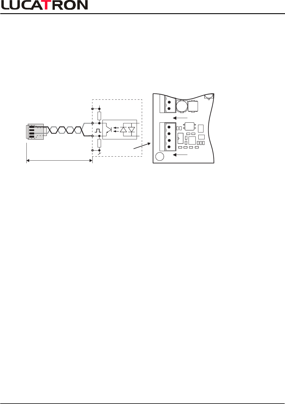
3. Deactivator DAV-100 Synchronization
In a “Checkout System Installation” the deactivator DAV-100 can be synchronized by cable.
3.1. Cable Synchronization
A twisted cable must be connected between the TX Board and the Deactivator Electronic. The cable
must be as short as possible, not longer than 3 meters (see figures below). To prevent resonance,
ferrites must be mounted on the Synchronization Cable.
OUT1
OUT2
er (X2)
(- -)
SYNC (X3)
D+ GND
- OUT
(+SYNC-)
SYNC OUT Deact.
X3 12VDEAC
1
2
3
4
+
1234
RJ10 Plug
SYNC OUT
to Deact.
UTB-100To DAV-100
max. 3 meters
Synchronization Wiring TX Layout
For more information, see Deactivator DAV-100 Short Instructions.
Note: The UTB-100A is NOT optimized for cable synchronization.
DEACTIVATOR SYNC
UTB-100 TX Tuning Guide
LUCATRON AG
CH-8606 Greifensee, Switzerland Version 1.0 Page 9
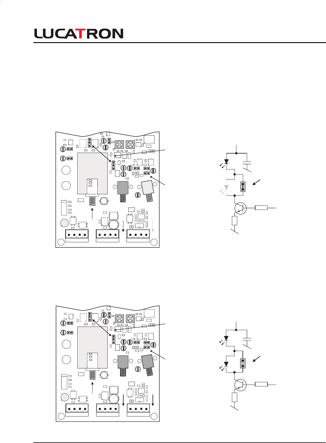
4. Opto TX Setup
On the UTB-100 are two (2) Optional Opto Output Sockets. It is possible connect one or two Opto
TX-Modules on the board. If only one Opto TX-Module is needed, it must be in socket OUT1.
To configure the Opto TX Output(s) see figures below.
4.1. One (1) Opto TX Output
• Insert the module into socket OUT1
• J10 must be IN
J10
IN
TX
Master
OUT1
OUT2
P14
P1 P2
P11
P9 P13
P8
P10
P12
J6
J2
J5 J9
J10 J8
J3
Power (X1)
(+ +) (- -)
Power (X2)
(+ +) (- -)
SYNC (X3)
D+ GND
IN
+ IN - IN + OUT - OUT
(+SYNC-)
SYNC OUT Deact.
J7
Opto1
(Optional)
Opto2
(Optional)
1
Master / Slave
Fuse
Filter
Filter
630mA
1
T
Layout One Opto TX Output Circuit One Opto TX Output
4.2. Two (2) Opto TX Output
• Insert the modules into socket OUT1 and socket OUT2
• J10 must be OUT
J10
OUT
TX
Master
OUT1
OUT2
P14
P1 P2
P11
P9 P13
P8
P10
P12
J6
J2
J5 J9
J10 J8
J3
Power (X1)
(+ +) (- -)
Power (X2)
(+ +) (- -)
SYNC (X3)
D+ GND
IN
+ IN - IN + OUT - OUT
(+SYNC-)
SYNC OUT Deact.
J7
Opto1
(Optional)
Opto2
(Optional)
1
Master / Slave
Fuse
Filter
Filter
630mA
1
T
Layout One Opto TX Output Circuit One Opto TX Output
Opto
TX 2
Opto
TX 2
Opto
TX 1
J10
+ 12V
J10 must
be IN, if
only
Opto TX1
is used
Opto
TX 2
Opto
TX 2
Opto
TX 1
J10
+ 12V
J10
OUT
OPTO TX SETUP
UTB-100 TX Tuning Guide
LUCATRON AG
CH-8606 Greifensee, Switzerland Version 1.0 Page 10
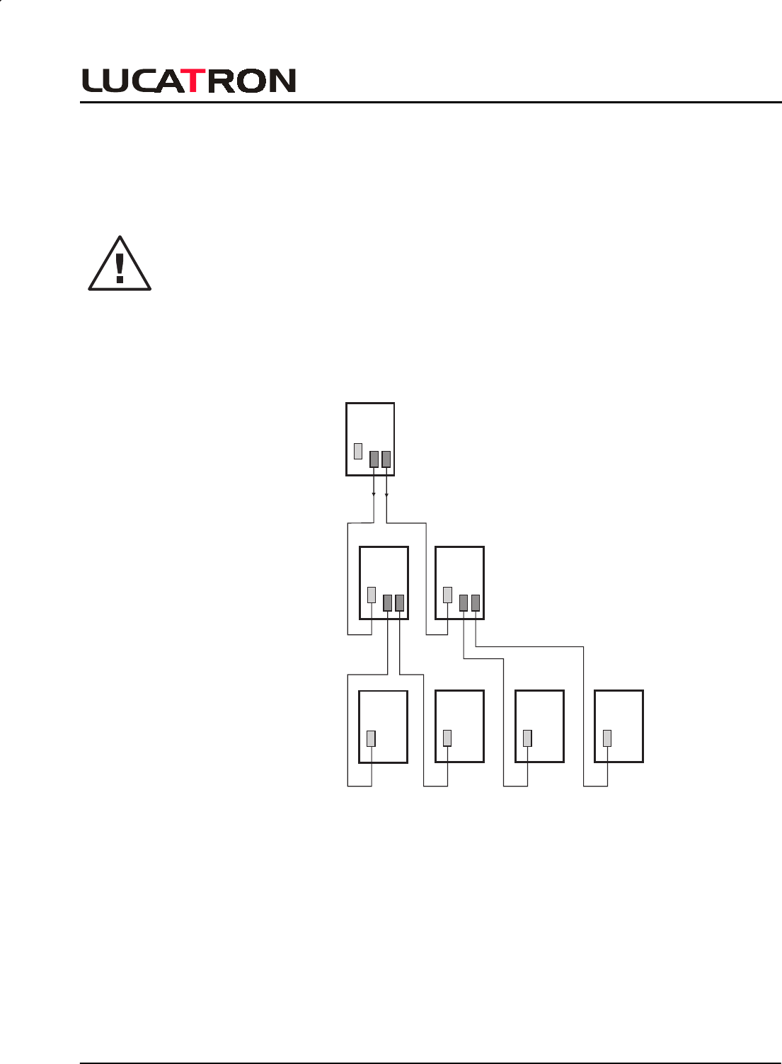
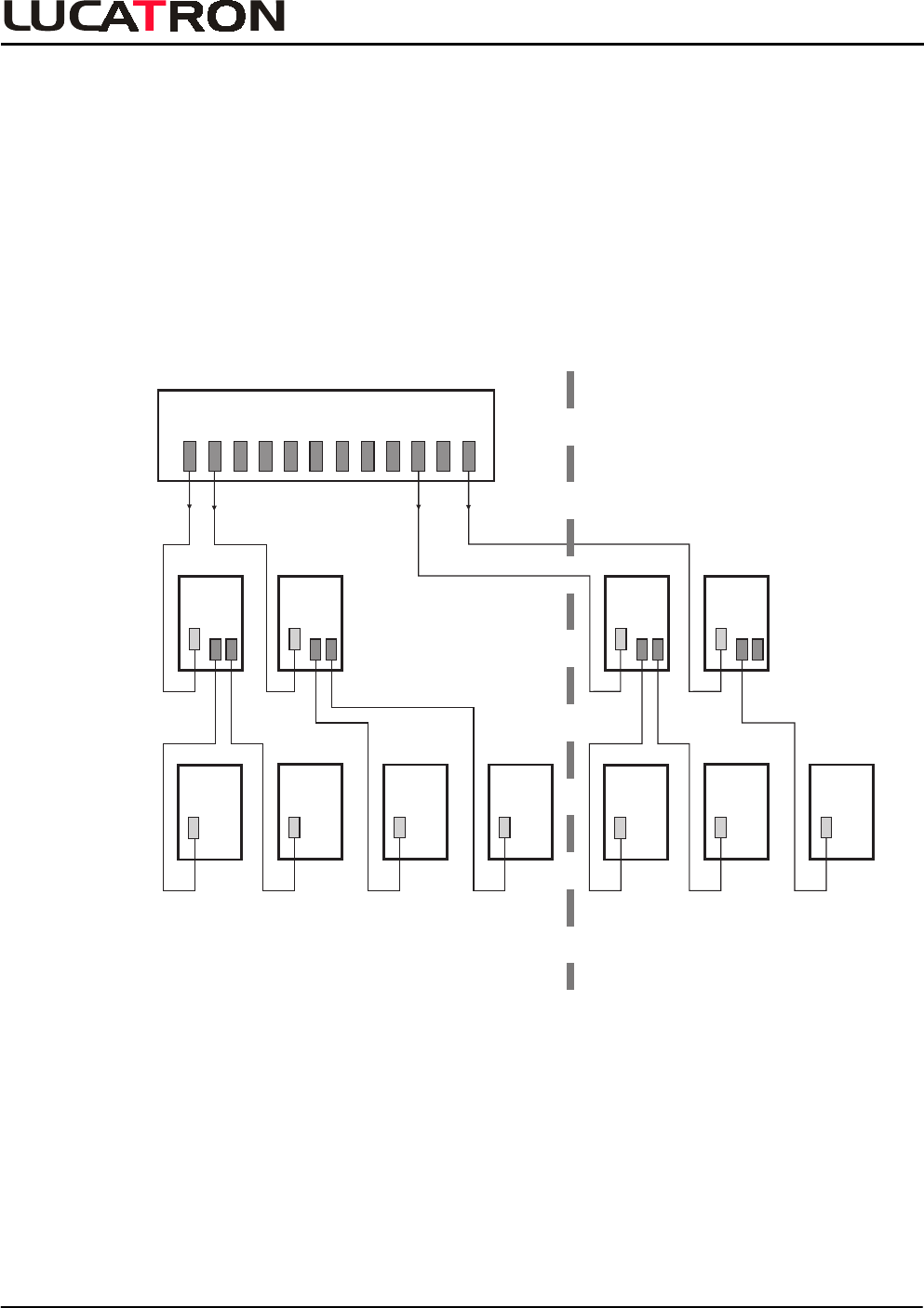
5. Installation Configurations
Since the UTB-100 can be used as a synchronization master, repeater or slave, installations can be
flexibly configured.
Basically there exists only one rule that has to be considered:
The optically transmitted synchronization signal may be repeated only once; therefore no
synchronization repeater should ever feed another repeater.
A basic configuration following this rule is shown below. The TX board of level 1 (bi-opto version,
configured as master) feeds the synchronization signal to the two TX boards of level 2 (bi-opto
version, configured as slave).
Level 1
Master
Rack
Level 3
Slave
TX Board(s)
used as
(Setting)
Level 2
Repeater
TX Board(s)
used as
(Slave
Setting)
TX
IN
OUT
TX
IN
OUT
TX
IN
TX
IN
TX
IN
TX
IN
Opto
IN
Opto
IN
Opto
IN
Opto
IN
Opto
IN
Opto
IN
Opto OUT
Opto OUT
TX
IN
OUT
TX Opto Cabling Hierarchy
(Only one (1) repeater level allowed)
INSTALLATION
UTB-100 TX Tuning Guide
LUCATRON AG
CH-8606 Greifensee, Switzerland Version 1.0 Page 11
These two boards, acting as synchronization repeaters, in turn each feed their optically transmitted
signal to two following TX boards of level 3 (standard version, configured as slave). This way, a
synchronization cluster of 7 transmitters has been created without use of a master rack.
lf a system consists of more than seven transmitters, a master rack has to be used as a
synchronization source. The optical signal of a master rack may be repeated once if necessary as
well.
A possible configuration using a master rack and UTB-100 is shown below.
Level 1
Master
Rack
Level 3
Slave
TX Board(s)
used as
(Slave Setting)
Level 2
Repeater
(Slave Setting)
TX Board(s)
used as
TX
IN
OUT
TX
IN
OUT
TX
IN
TX
IN
TX
IN
TX
IN
Opto
IN
Opto
IN
Opto
IN
Opto
IN
Opto
IN
Opto
IN
Opto OUT
Opto OUT
Master Rack
TX
IN
OUT
TX
IN
OUT
TX
IN
TX
IN
TX
IN
Opto
IN
Opto
IN
Opto
IN
Opto
IN
Opto
IN
Opto OUT
Shop A Shop B
B1 B2
TX Opto Cabling from Master Rack
INSTALLATION
UTB-100 TX Tuning Guide
LUCATRON AG
CH-8606 Greifensee, Switzerland Version 1.0 Page 12
6. Tuning
Step-by-step instructions for tuning the UTB-100 board follow. For the receiver see RX Tuning Guide.
6.1. Recommended Tools
The following instruments are recommended for tuning:
−
−−
−
battery powered oscilloscope (two channels, cursor readout function recommended).
−
−−
−
10: 1 oscilloscope probe.
−
−−
−
Multimeter.
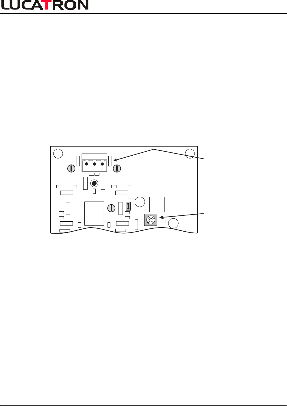
6.2. Preparation
• Power OFF the TX board (remove PWR connector at socket X1).
• Ensure that the antenna is connected to the correct socket (X4) on the TX board (see
drawing below).
Amplitude
P7
GND
P5
P4
R147
LVL
J1
IN GND IN
Antenna(X4)
ANTANT GND
UTB - 100
Antenna
Connector
X4
TX Layout
TUNING
UTB-100 TX Tuning Guide
LUCATRON AG
CH-8606 Greifensee, Switzerland Version 1.0 Page 13
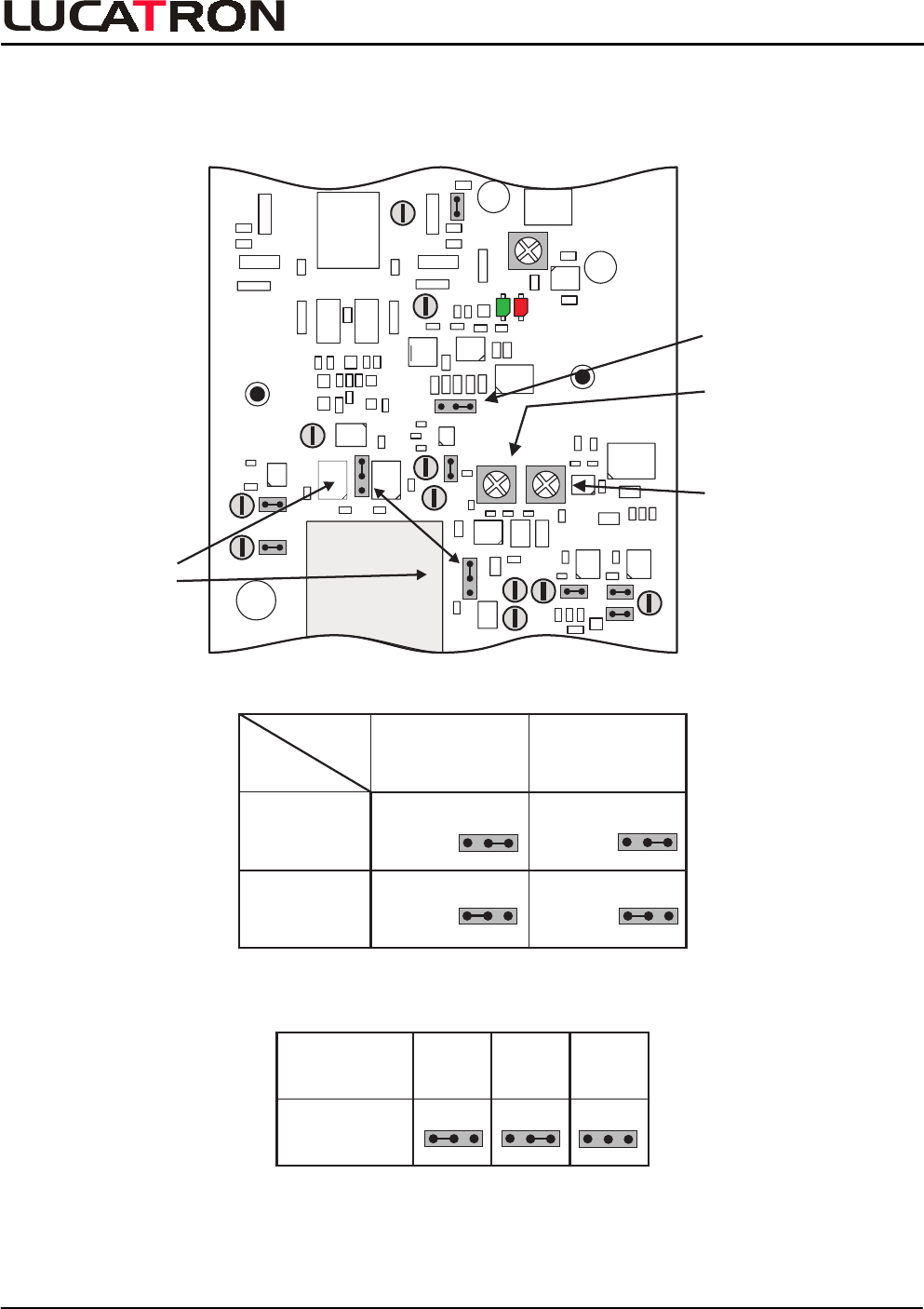
• Turn the amplitude potentiometer R147 (LVL to almost (7/8) full power (clockwise).
• Check the default setting of jumper J2 to J4 (see following two tables).
Modulation
Frequency
J4
P1 P2
P11
P9 P13
P3
P8
P10
P12
GND
GND
P6 P7
R168
FREQ
R161
DEV
R147
LVL
J1
J4
J6
J2
J5 J9
10 J8
J3
J7
1
Master / Slave
1
TEMP
READY
Deviation
Frequency
1
Master/
Slave
J2+J3
TX Layout
Jumper
Config.
J2
J3
* Master 2-3 IN 2-3 IN
Slave 1-2 IN 1-2 IN
123 123
123 123
Master / Slave Jumper Settings
Frequenz(Hz) *82 85 79
J4
123 123123
Sweep Frequency
* Factory default setting
TUNING
UTB-100 TX Tuning Guide
LUCATRON AG
CH-8606 Greifensee, Switzerland Version 1.0 Page 14
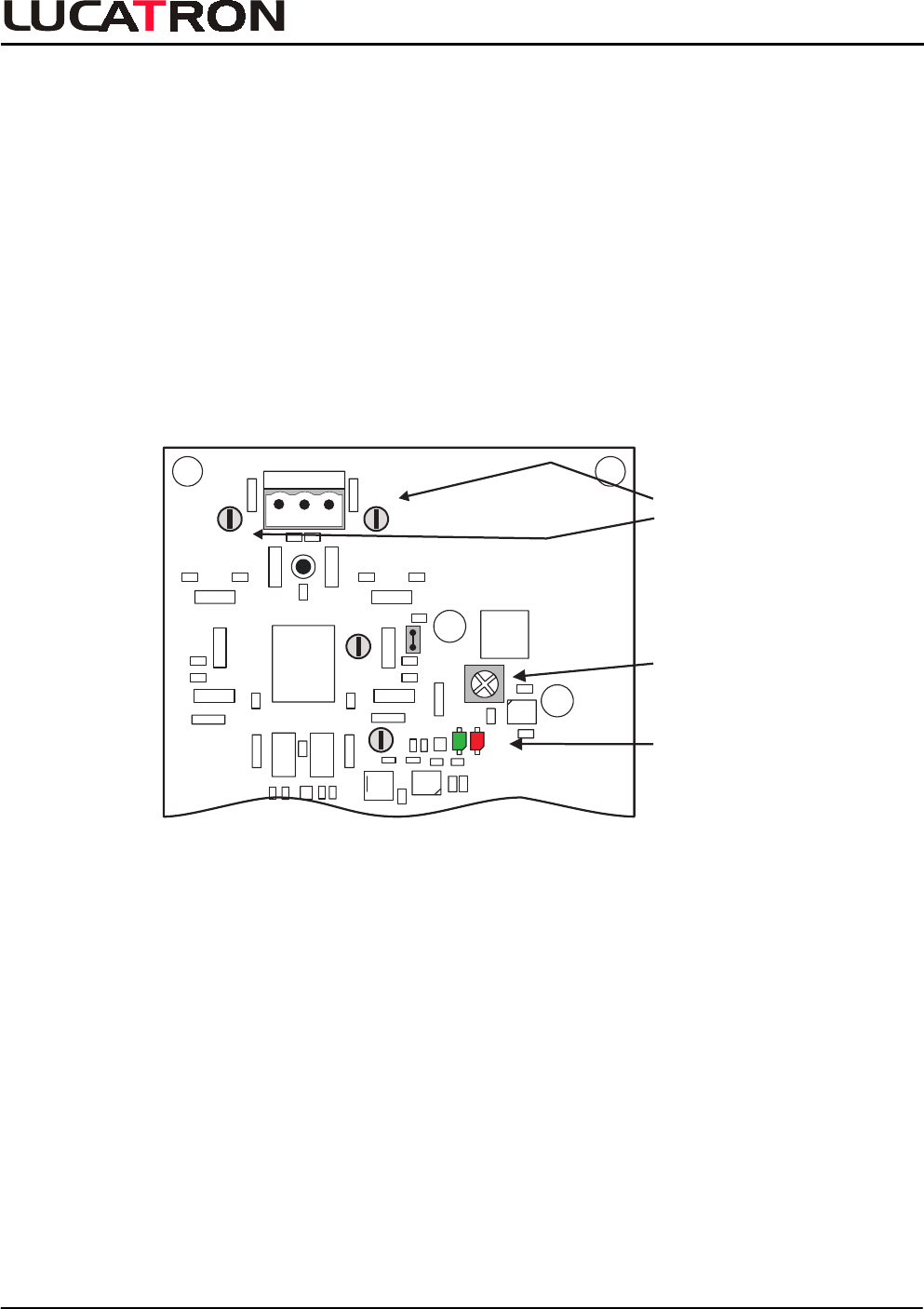
6.3. Power On Adjustments
• Power ON the TX board (insert PWR connector at socket X1).
• Check the red Temp-Limit LED (H102) is ON: Operation OK.
• lf the LED is going OFF and ON:
−
−−
−
reduce the emitted power with the amplitude potentiometer R147.
−
−−
−
exchange TX board.
−
−−
−
check antenna, matching board for short circuit and so on.
• As an option, check the emitted signal at both of the corresponding test points located to
the left and right of the antenna connector (P4
/
GND and P5
/
GND; see figure below). The
signal shapes may be varying. A signal breakdown or variation of more than 20% of
average the value indicates a faulty transmitter or antenna.
Remark: The signal on P4 and P5 is usually not identical.
Amplitude
LVL
P6 P7
GND
P5
P4
R147
LVL
J1
IN GND IN
Antenna(X4)
ANTANT GND
TEMP
READY
UTB - 100
Test Points
P4/GND,
P5/GND
Temp-
Limit
TX Layout
• Proceed with the RX board according to the instructions in the RX Tuning Guide.
Hints: lf the HF power received at the RX is too high:
−
−−
−
insert the “Narrow” jumper on the RX board.
−
−−
−
reduce the TX power.
POWER ON
UTB-100 TX Tuning Guide
LUCATRON AG
CH-8606 Greifensee, Switzerland Version 1.0 Page 15
7. Appendix
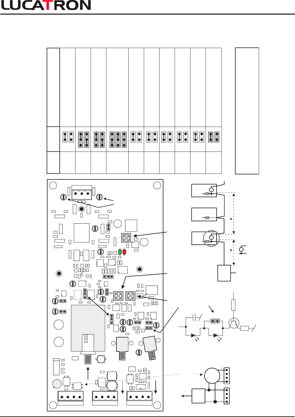
7.1. Compressed Overview
Amplitude
OUT1
OUT2
P14
P1 P2
P11
P9 P13
P3
P8
P10
P12
GND
GND
P6 P7
GND
P5
P4
R168
FREQ
R161
DEV
R147
LVL
J1
J4
J6
J2
J5 J9
J10 J8
J3
Power (X1)
(+ +) (- -)
Power (X2)
(+ +) (- -)
SYNC (X3)
D+ GND
IN GND IN
Antenna(X4)
IN
+IN -IN + OUT - OUT
(+SYNC-)
SYNC OUT Deact.
J7
Opto1
(Optional)
Opto2
(Optional)
1
Master / Slave
1
ANTANT GND
TEMP
READY
Deviation Frequency
UTB - 100
Filter
Filter
OUT
Additional
Filter
X1
++--
IN
X2
++--
Input Voltage
18-20 VAC or 20-24 VDC
RX
Power
Supply
AC or DC
+ Filter
1.5 4m 5m
TX
F
TX
F
-
Unfiltered Length
230/110
VAC
18 VAC or
20 VDC
F
Represents additional Filter
Opto
TX 2
Opto
TX 1
J10
+ 12V
Fuse
Filter
Filter
630mA
J10 must
be IN, if
only
Opto TX1
is used
Filter Layout Installation Example
Opto TX Circuit
LUCA RONT
Output Vpp
Jumper Table
UTB-100 (8600628A)
1
Jumper Settings Function
J1
J2
J3
Connects Ampl. Control (Default)
Factory use only
Master (Default)
Slave
Master (Default)
Slave
123
82 Hz, Modulation Frequency (Def.)
85 Hz, Modulation Frequency
79 Hz, Modulation Frequency
J4
J5
J6
J7
J8
J9
+ 24 Volt (Default)
Factory use only
+ 5 Volt, VA (Default)
Factory use only
+ 12 Volt (Default)
Factory use only
Opto TX1 only (Default)
Opto TX1 + TX2
+ 5 Volt (Default)
Factory use only
+ 12 Volt, VA (Default)
Factory use only
J10
123
123
SYNC OUT Deact.
(see DAV-100 Short Instructions)
T
Caution: Deviaton must be between
7.5 and 8.9 MHz or less
APPENDI
X