Siemens WTPIWLAN-V200 SIMATIC WTP 277F IWLAN User Manual Wireless Teach Pendant F IWLAN V2
Siemens AG SIMATIC WTP 277F IWLAN Wireless Teach Pendant F IWLAN V2
Siemens >
Contents
- 1. Users Manual p1
- 2. Users Manual p2
- 3. Users Manual p3
Users Manual p1

Wireless Teach Pendant F IWLAN V2
_
_________________
_
_
_________________
_
_
_____
_
____________
_
_________________
_
_
_________________
_
_
_________________
_
_
_________________
_
_
_________________
_
_
_________________
_
_
_________________
_
_
_________________
_
_
_________________
_
_
_________________
_
_
_________________
_
_
_________________
_
_
_______________
_
__
SIMATIC HMI
HMI device
Wireless Teach Pendant F IWLAN
V2
Operating Instructions
08/2010
A5E02453837-01
Preface
Overview
1
Safety instructions and
standards
2
Planning the use
3
Mounting and connection
4
Operator controls and
displays
5
Configuring the HMI device
6
Safety-related configuration
7
Commissioning a project
8
Commissioning the plant
9
Fail-safe operation
10
Operating a project
11
Service and maintenance
12
Technical specifications
13
Appendix
A
Abbreviations
B
PRELIMINARY II
1.7.2010
Legal information
Legal information
Warning notice system
This manual contains notices you have to observe in order to ensure your personal safety, as well as to prevent
damage to property. The notices referring to your personal safety are highlighted in the manual by a safety alert
symbol, notices referring only to property damage have no safety alert symbol. These notices shown below are
graded according to the degree of danger.
DANGER
indicates that death or severe personal injury will result if proper precautions are not taken.
WARNING
indicates that death or severe personal injury may result if proper precautions are not taken.
CAUTION
with a safety alert symbol, indicates that minor personal injury can result if proper precautions are not taken.
CAUTION
without a safety alert symbol, indicates that property damage can result if proper precautions are not taken.
NOTICE
indicates that an unintended result or situation can occur if the corresponding information is not taken into
account.
If more than one degree of danger is present, the warning notice representing the highest degree of danger will
be used. A notice warning of injury to persons with a safety alert symbol may also include a warning relating to
property damage.
Qualified Personnel
The product/system described in this documentation may be operated only by personnel qualified for the specific
task in accordance with the relevant documentation for the specific task, in particular its warning notices and
safety instructions. Qualified personnel are those who, based on their training and experience, are capable of
identifying risks and avoiding potential hazards when working with these products/systems.
Proper use of Siemens products
Note the following:
WARNING
Siemens products may only be used for the applications described in the catalog and in the relevant technical
documentation. If products and components from other manufacturers are used, these must be recommended
or approved by Siemens. Proper transport, storage, installation, assembly, commissioning, operation and
maintenance are required to ensure that the products operate safely and without any problems. The permissible
ambient conditions must be adhered to. The information in the relevant documentation must be observed.
Trademarks
All names identified by ® are registered trademarks of the Siemens AG. The remaining trademarks in this
publication may be trademarks whose use by third parties for their own purposes could violate the rights of the
owner.
Disclaimer of Liability
We have reviewed the contents of this publication to ensure consistency with the hardware and software
described. Since variance cannot be precluded entirely, we cannot guarantee full consistency. However, the
information in this publication is reviewed regularly and any necessary corrections are included in subsequent
editions.
Siemens AG
Industry Sector
Postfach 48 48
90026 NÜRNBERG
GERMANY
A5E02453837-01
Ⓟ 06/2010
Copyright © Siemens AG 2010.
Technical data subject to change
PRELIMINARY II
1.7.2010

Wireless Teach Pendant F IWLAN V2
Operating Instructions, 08/2010, A5E02453837-01 3
Preface
Purpose of the operating instructions
These operating instructions provide information for manuals derived from the requirements
for mechanical engineering documentation according to DIN EN 62079. This information
relates to the place of use, transport, storage, mounting, use and maintenance.
These operating instructions are intended for:
● Users
● Commissioning engineers
● Maintenance personnel
Pay particular attention to the section "Safety instructions and standards (Page 35)".
You can find more information such as operating instructions, examples and reference
information in the online help of WinCC flexible.
Required knowledge
General knowledge of automation technology and process communication is needed to
understand the operating instructions.
It is also assumed that those using the manual have experience in using personal computers
and an understanding of Microsoft operating systems.
Scope of this manual
The manual applies to the "Wireless Teach Pendant F IWLAN V2" HMI device in
combination with the following software:
● STEP 7 V5.4, as of SP2
● Add-on package "S7 Distributed Safety", V5.4, as of SP3
● WinCC flexible 2008, SP2
NOTICE
Manual belongs to HMI device
The supplied manual belongs to the HMI device and is also required to repeat
commissioning. Keep all supplied and supplementary documentation for the entire
service life of the HMI device.
Provide all stored documents to subsequent owners of the HMI device.
PRELIMINARY II
1.7.2010

Preface
Wireless Teach Pendant F IWLAN V2
4 Operating Instructions, 08/2010, A5E02453837-01
Trademarks
The following names marked with the ® symbol are registered trademarks of Siemens AG:
● HMI®
● SIMATIC®
● WinCC®
Style conventions
This manual uses the following style conventions.
Style Convention Scope
"Add screen" Terminology that appears in the user interface, for example
dialog names, tabs, buttons, menu commands
Required input, for example, limits, tag values.
Path information
"File > Edit" Operational sequences, for example, shortcut menu commands
<F1>, <Alt+P> Keyboard operation
Please observe notes labeled as follows:
Note
A
note contains important information about the product described in the manual and its use,
or a specific section of the manual to which you should pay particular attention.
Naming conventions
This manual uses the following naming conventions.
Term Applies to
Plant System
Machining center
One or more machines
Actuate By means of the touch screen on the HMI device
By operating a mouse on the HMI device
Range name Describes an effective range which is recognized by an
HMI device
Figures
This manual contains illustrations of the described devices. The illustrations can deviate from
the described device as originally supplied.
PRELIMINARY II
1.7.2010

Preface
Wireless Teach Pendant F IWLAN V2
Operating Instructions, 08/2010, A5E02453837-01 5
Technical Support
Technical support for the products covered in the manual is available in the Internet at:
● Technical Support
(http://support.automation.siemens.com)
● Support Request
(http://support.automation.siemens.com/WW/view/en/16605654)
● Service
(http://support.automation.siemens.com/WW/view/en/16604318)
● Contacts and office locations
(http://www.automation.siemens.com/mcms/aspa-db/en/Pages/default.aspx)
● Training center
(http://sitrain.automation.siemens.com/sitrain/default.aspx?AppLang=en)
Additional information on SIMATIC products is available in the Internet at:
● Industry Portal
(http://www.automation.siemens.com/_en/portal/index.htm)
● Overall SIMATIC documentation
(http://www.automation.siemens.com/simatic/portal/html_76/techdoku.htm)
Recycling and disposal
The products described in this manual are recyclable because of the low level of
contaminants in its components. Contact a certified disposal service company for
environmentally sound recycling and disposal of your old devices.
Used batteries and rechargeable batteries
Used batteries and lithium ion batteries are hazardous waste. Always dispose of used
batteries and lithium ion batteries in accordance with the regulations in effect. Identify the
container provided for this purpose with the label, "Used batteries and rechargeables".
Note
Batteries and rechargeables do not belong in the garbage. The user is legally obliged to
return used batteries and rechargeable batteries. You can deposit used batteries and
rechargeables at any public collection site and anywhere batteries or rechargeables of
similar type are sold.
You can also send batteries and rechargeables to the following address:
Siemens AG
Industry Sector
Returns Center
Siemensstr. 2
90766 Fürth
Germany
PRELIMINARY II
1.7.2010

Wireless Teach Pendant F IWLAN V2
Operating Instructions, 08/2010, A5E02453837-01 7
Table of contents
Preface ...................................................................................................................................................... 3
1 Overview.................................................................................................................................................. 13
1.1 Product overview .........................................................................................................................13
1.2 Scope of delivery .........................................................................................................................13
1.3 Wireless Teach Pendant F IWLAN ..............................................................................................14
1.4 Main rechargeable battery ...........................................................................................................16
1.5 Accessories..................................................................................................................................16
1.6 Equipment for HMI device and plant............................................................................................17
1.6.1 Overview ......................................................................................................................................17
1.6.2 Docking station.............................................................................................................................17
1.6.3 Charger°.......................................................................................................................................18
1.6.4 Power supply unit.........................................................................................................................19
1.6.5 RFID tag.......................................................................................................................................20
1.6.6 Access point.................................................................................................................................21
1.7 Communication and approved controllers ...................................................................................22
1.8 Software requirements.................................................................................................................22
1.9 Supported WinCC flexible objects ...............................................................................................23
1.10 Configuration and process control phases ..................................................................................26
1.11 Areas in the RFID tag system......................................................................................................27
1.12 Rapid roaming..............................................................................................................................29
1.13 Terms for fail-safe operation ........................................................................................................32
2 Safety instructions and standards............................................................................................................ 35
2.1 Safety instructions........................................................................................................................35
2.2 Approvals .....................................................................................................................................36
2.3 Standards on operating safety.....................................................................................................38
2.4 Operating conditions ....................................................................................................................39
2.5 Risk analysis of the plant .............................................................................................................40
2.6 Safety functions of the EMERGENCY STOP button ...................................................................41
2.7 Safety functions of the enabling mechanism ...............................................................................42
2.8 Electromagnetic compatibility ......................................................................................................44
2.9 Transport and storage conditions ................................................................................................46
3 Planning the use...................................................................................................................................... 47
3.1 Checklist.......................................................................................................................................47
3.2 Operating conditions ....................................................................................................................48
PRELIMINARY II
1.7.2010

Table of contents
Wireless Teach Pendant F IWLAN V2
8 Operating Instructions, 08/2010, A5E02453837-01
3.3 Insulation resistance, protection class and degree of protection................................................ 50
3.4 WLAN properties......................................................................................................................... 51
3.5 Planning protection zones in the RFID tag system..................................................................... 52
3.6 Planning an installation location for RFID tags ........................................................................... 54
3.7 Planning the installation location and clearance of the docking station...................................... 56
3.8 Planning the installation location of signal lamps ....................................................................... 57
3.9 Coexistence of the frequency bands........................................................................................... 58
3.10 Planning information security...................................................................................................... 59
4 Mounting and connection......................................................................................................................... 63
4.1 Check the scope of delivery........................................................................................................ 63
4.2 Installing an RFID tag.................................................................................................................. 63
4.3 Installing the docking station....................................................................................................... 64
4.4 Connecting the docking station and charger............................................................................... 65
4.5 Connecting the HMI device......................................................................................................... 66
4.5.1 Safety instructions....................................................................................................................... 66
4.5.2 Opening and closing the terminal compartment ......................................................................... 67
4.5.3 Ports and reset button................................................................................................................. 68
4.5.4 Inserting a memory card ............................................................................................................. 69
4.5.5 Connecting the rechargeable buffer battery................................................................................ 71
4.5.6 Replacing and charging the main rechargeable battery ............................................................. 72
4.5.6.1 Safety instructions....................................................................................................................... 72
4.5.6.2 Replacing the main rechargeable battery ................................................................................... 73
4.5.6.3 Charging the main rechargeable battery..................................................................................... 75
4.5.6.4 Showing the battery charge ........................................................................................................ 76
4.5.7 Connecting the PLC.................................................................................................................... 77
4.5.8 Connecting the configuration PC ................................................................................................ 78
4.5.9 Connecting a USB device ........................................................................................................... 80
4.6 Switching on and testing the HMI device....................................................................................81
4.7 Switching off the HMI device....................................................................................................... 82
5 Operator controls and displays ................................................................................................................ 83
5.1 Overview ..................................................................................................................................... 83
5.2 LED display ................................................................................................................................. 85
5.3 Power management.................................................................................................................... 87
5.4 Safety-related operator controls.................................................................................................. 88
5.4.1 EMERGENCY STOP button ....................................................................................................... 88
5.4.2 Enabling button ........................................................................................................................... 90
5.4.3 Testing the function..................................................................................................................... 92
5.5 Operator controls ........................................................................................................................ 93
5.5.1 Operating the rotary switch ......................................................................................................... 93
5.5.2 Operating the illuminated push-button........................................................................................ 93
5.5.3 Evaluating operator controls ....................................................................................................... 93
5.5.3.1 Overview ..................................................................................................................................... 93
5.5.3.2 Evaluating operator controls as direct keys ................................................................................ 94
5.6 Holding, operating and setting down the HMI device ................................................................. 95
PRELIMINARY II
1.7.2010

Table of contents
Wireless Teach Pendant F IWLAN V2
Operating Instructions, 08/2010, A5E02453837-01 9
6 Configuring the HMI device...................................................................................................................... 97
6.1 Desktop and Loader.....................................................................................................................97
6.2 Operator input options ...............................................................................................................100
6.3 Enabling and disabling SecureMode .........................................................................................101
6.4 Control Panel .............................................................................................................................102
6.4.1 Overview ....................................................................................................................................102
6.4.2 Functions in the Control Panel...................................................................................................102
6.4.3 Operating the Control Panel ......................................................................................................104
6.4.4 Using the screen keyboard in the Control Panel .......................................................................104
6.4.5 Changing settings for operation.................................................................................................107
6.4.5.1 Configuring the screen keyboard...............................................................................................107
6.4.5.2 Changing display brightness......................................................................................................108
6.4.5.3 Setting the character repeat rate of the screen keyboard .........................................................109
6.4.5.4 Setting the double-click..............................................................................................................110
6.4.5.5 Calibrating the touch screen ......................................................................................................111
6.4.5.6 Starting the HMI device again....................................................................................................113
6.5 Entering and deleting a password..............................................................................................114
6.6 Configuring the WLAN connection.............................................................................................116
6.7 Changing and displaying general settings.................................................................................125
6.7.1 Setting the date and time...........................................................................................................125
6.7.2 Regional and language settings.................................................................................................127
6.7.3 Setting the screen saver ............................................................................................................127
6.7.4 Setting the location of the project...............................................................................................130
6.7.5 Setting the delay time for the project .........................................................................................131
6.7.6 Enabling sound and setting sound volume................................................................................132
6.7.7 Backing up registry information and temporary data .................................................................133
6.7.8 Displaying general system properties........................................................................................134
6.7.9 Displaying memory distribution..................................................................................................134
6.7.10 Displaying information about the HMI device ............................................................................135
6.7.11 Activate memory management ..................................................................................................136
6.7.12 Display firmware ........................................................................................................................137
6.7.13 Displaying licensing information.................................................................................................137
6.7.14 Displaying the charge status of the batteries.............................................................................138
6.8 Enabling PROFINET IO.............................................................................................................138
6.9 Setting the PROFIsafe address .................................................................................................140
6.10 Reassigning an RFID tag ID ......................................................................................................141
6.11 Programming the data channel..................................................................................................142
6.12 Configuring network operation...................................................................................................143
6.12.1 Overview ....................................................................................................................................143
6.12.2 Specifying the computer name of the HMI device .....................................................................145
6.12.3 Specifying the IP address and name server..............................................................................146
6.12.4 Specifying the logon data...........................................................................................................148
6.12.5 Configuring e-mail......................................................................................................................148
6.13 Changing Internet settings.........................................................................................................151
6.13.1 Changing general settings .........................................................................................................151
6.13.2 Setting the proxy server .............................................................................................................152
6.13.3 Changing Internet security settings ...........................................................................................153
6.13.4 Importing, displaying and deleting certificates...........................................................................154
PRELIMINARY II
1.7.2010

Table of contents
Wireless Teach Pendant F IWLAN V2
10 Operating Instructions, 08/2010, A5E02453837-01
6.14 Saving to external storage medium – backup........................................................................... 156
6.15 Restoring from external storage medium – Restore ................................................................. 157
7 Safety-related configuration................................................................................................................... 161
7.1 General procedure .................................................................................................................... 161
7.2 Checklist for configuration......................................................................................................... 162
7.3 SIMATIC STEP 7 ...................................................................................................................... 163
7.3.1 Configuring in STEP 7............................................................................................................... 163
7.3.2 Assigning parameters for communication between the HMI device and the controller............ 163
7.3.3 "SIMATIC S7 Distributed Safety" add-on.................................................................................. 166
7.3.4 Checklist for EMERGENCY STOP configuration...................................................................... 167
7.3.5 Using F-FBs .............................................................................................................................. 168
7.3.6 F_FB_MP................................................................................................................................... 171
7.3.7 F_FB_RNG_4 and F_FB_RNG_16............................................................................................ 174
7.4 Configuration in WinCC flexible ................................................................................................ 179
8 Commissioning a project........................................................................................................................ 181
8.1 Using an existing project........................................................................................................... 181
8.2 Operating modes....................................................................................................................... 181
8.3 Available data channels ............................................................................................................ 182
8.4 Preparing and backing up a project .......................................................................................... 183
8.4.1 Overview ................................................................................................................................... 183
8.4.2 Transfer..................................................................................................................................... 183
8.4.2.1 Overview ................................................................................................................................... 183
8.4.2.2 Starting manual transfer............................................................................................................ 184
8.4.2.3 Starting backtransfer................................................................................................................. 185
8.4.3 Testing a project........................................................................................................................ 186
8.4.4 Backup and restore ................................................................................................................... 187
8.4.4.1 Overview ................................................................................................................................... 187
8.4.4.2 Backing up with WinCC flexible ................................................................................................ 188
8.4.4.3 Restoring with WinCC flexible................................................................................................... 189
8.4.4.4 Backing up with ProSave .......................................................................................................... 190
8.4.4.5 Restoring with ProSave............................................................................................................. 190
8.4.5 Updating the operating system ................................................................................................. 191
8.4.5.1 Overview ................................................................................................................................... 191
8.4.5.2 Updating the operating system using WinCC flexible............................................................... 192
8.4.5.3 Updating the operating system using ProSave......................................................................... 193
8.4.6 Restoring factory settings.......................................................................................................... 194
8.4.6.1 Overview ................................................................................................................................... 194
8.4.6.2 Restoring the factory settings using WinCC flexible................................................................. 194
8.4.6.3 Restoring the factory settings with ProSave ............................................................................. 197
8.5 Commissioning an RFID tag ..................................................................................................... 199
8.6 Replacing an RFID tag.............................................................................................................. 202
9 Commissioning the plant........................................................................................................................ 203
9.1 Overview ................................................................................................................................... 203
9.2 Acceptance of the plant............................................................................................................. 203
9.3 Diagnostics................................................................................................................................ 204
PRELIMINARY II
1.7.2010

Table of contents
Wireless Teach Pendant F IWLAN V2
Operating Instructions, 08/2010, A5E02453837-01 11
10 Fail-safe operation................................................................................................................................. 207
10.1 Organizational measures ...........................................................................................................207
10.2 Switch-off behavior ....................................................................................................................208
10.3 Integrating the HMI device.........................................................................................................209
10.4 Logging onto a machine.............................................................................................................210
10.5 Logging off the machine.............................................................................................................212
10.6 Removing the HMI device..........................................................................................................213
11 Operating a project ................................................................................................................................ 215
11.1 Starting the project.....................................................................................................................215
11.2 Operator input options ...............................................................................................................217
11.3 Direct keys .................................................................................................................................219
11.4 Setting the project language ......................................................................................................220
11.5 Operating the screen keyboard in the project............................................................................220
11.6 Device-specific displays.............................................................................................................224
11.6.1 Overview ....................................................................................................................................224
11.6.2 Showing the battery charge .......................................................................................................224
11.6.3 Displaying WLAN quality............................................................................................................225
11.6.4 Displaying the "Effective range name (RFID)" object ................................................................226
11.7 Project security ..........................................................................................................................226
11.7.1 Overview ....................................................................................................................................226
11.7.2 User View...................................................................................................................................228
11.7.3 User logon..................................................................................................................................230
11.7.4 User logoff..................................................................................................................................231
11.7.5 Creating users............................................................................................................................231
11.7.6 Changing user data....................................................................................................................233
11.7.7 Deleting users ............................................................................................................................234
11.8 Error cases in the project operation...........................................................................................235
11.9 Closing the project .....................................................................................................................236
12 Service and maintenance ...................................................................................................................... 237
12.1 Maintenance and care ...............................................................................................................237
12.2 Replacing the rechargeable buffer battery.................................................................................238
12.3 Spare parts and repairs .............................................................................................................239
PRELIMINARY II
1.7.2010

Table of contents
Wireless Teach Pendant F IWLAN V2
12 Operating Instructions, 08/2010, A5E02453837-01
13 Technical specifications......................................................................................................................... 241
13.1 Dimension drawings.................................................................................................................. 241
13.1.1 Wireless Teach Pendant F IWLAN ........................................................................................... 241
13.1.2 Docking station.......................................................................................................................... 242
13.1.3 RFID tag.................................................................................................................................... 243
13.2 Specifications ............................................................................................................................ 244
13.2.1 Wireless Teach Pendant F IWLAN V2...................................................................................... 244
13.2.2 Interface description.................................................................................................................. 246
13.2.3 Rechargeable batteries............................................................................................................. 248
13.2.4 Docking station.......................................................................................................................... 249
13.2.5 Charger ..................................................................................................................................... 249
13.2.6 RFID tag.................................................................................................................................... 250
13.2.7 F-FBs and configuration............................................................................................................ 250
A Appendix................................................................................................................................................ 251
A.1 ESD guideline ........................................................................................................................... 251
A.2 Typical operating procedures and potential fault scenarios...................................................... 253
A.2.1 Overview ................................................................................................................................... 253
A.2.2 Switch on the HMI device.......................................................................................................... 254
A.2.3 Integrating the HMI device ........................................................................................................ 255
A.2.4 Communication error for the integrated HMI device ................................................................. 256
A.2.5 Discrepancy error during enabling ............................................................................................ 258
A.2.5.1 The enabling button is askew ................................................................................................... 258
A.2.5.2 The enabling button is defective. .............................................................................................. 259
A.2.6 Logging onto a machine............................................................................................................ 260
A.2.7 Leaving a protection zone without logging off........................................................................... 262
A.2.8 Communication errors with logged on HMI device ................................................................... 263
A.2.9 Logging off the machine............................................................................................................ 264
A.2.10 Removing the HMI device......................................................................................................... 265
A.2.11 Switching off the HMI device..................................................................................................... 266
A.3 Example of an application......................................................................................................... 267
A.3.1 Configuration and operation...................................................................................................... 267
A.3.2 Configuring the controller and HMI device in STEP 7 .............................................................. 270
A.3.3 Safety program S7 Distributed Safety....................................................................................... 274
A.4 Safety-related messages .......................................................................................................... 279
A.5 System alarms .......................................................................................................................... 283
B Abbreviations......................................................................................................................................... 317
Glossary ................................................................................................................................................ 319
Index...................................................................................................................................................... 327
PRELIMINARY II
1.7.2010
Wireless Teach Pendant F IWLAN V2
Operating Instructions, 08/2010, A5E02453837-01 13
Overview 1
1.1 Product overview
Additional application scenarios with Wireless Teach Pendant F IWLAN
The Wireless Teach Pendant F IWLAN offers the option of implementing mobile safety
functions ("EMERGENCY STOP" and "Enabling") anywhere in the plant. The HMI device
communicates with the F-CPU via WLAN. The operator can operate the plant without
disturbing cables.
Safety-related control and monitoring in the fail-safe mode occurs within a protection zone on
a machine that is logged onto the Wireless Teach Pendant F IWLAN.
The Wireless Teach Pendant F IWLAN is characterized by short commissioning times, a
large user memory and high performance, and is optimized for projects based on
WinCC flexible.
Wireless Teach Pendant F IWLAN has the following features:
● Safety-related operator controls:
– EMERGENCY STOP button
– Enabling button
● Wireless operation with:
– IWLAN interface via PROFINET
– RFID
– Rechargeable battery
● 6.5" TFT screen with 65536 colors
● Extended HMI functions
1.2 Scope of delivery
The scope of delivery includes:
● 1 Wireless Teach Pendant F IWLAN with built-in buffer battery
● 1 main rechargeable battery
● 1 neck strap
● 1 grip strap
● 1 data medium
PRELIMINARY II
1.7.2010
Overview
1.3 Wireless Teach Pendant F IWLAN
Wireless Teach Pendant F IWLAN V2
14 Operating Instructions, 08/2010, A5E02453837-01
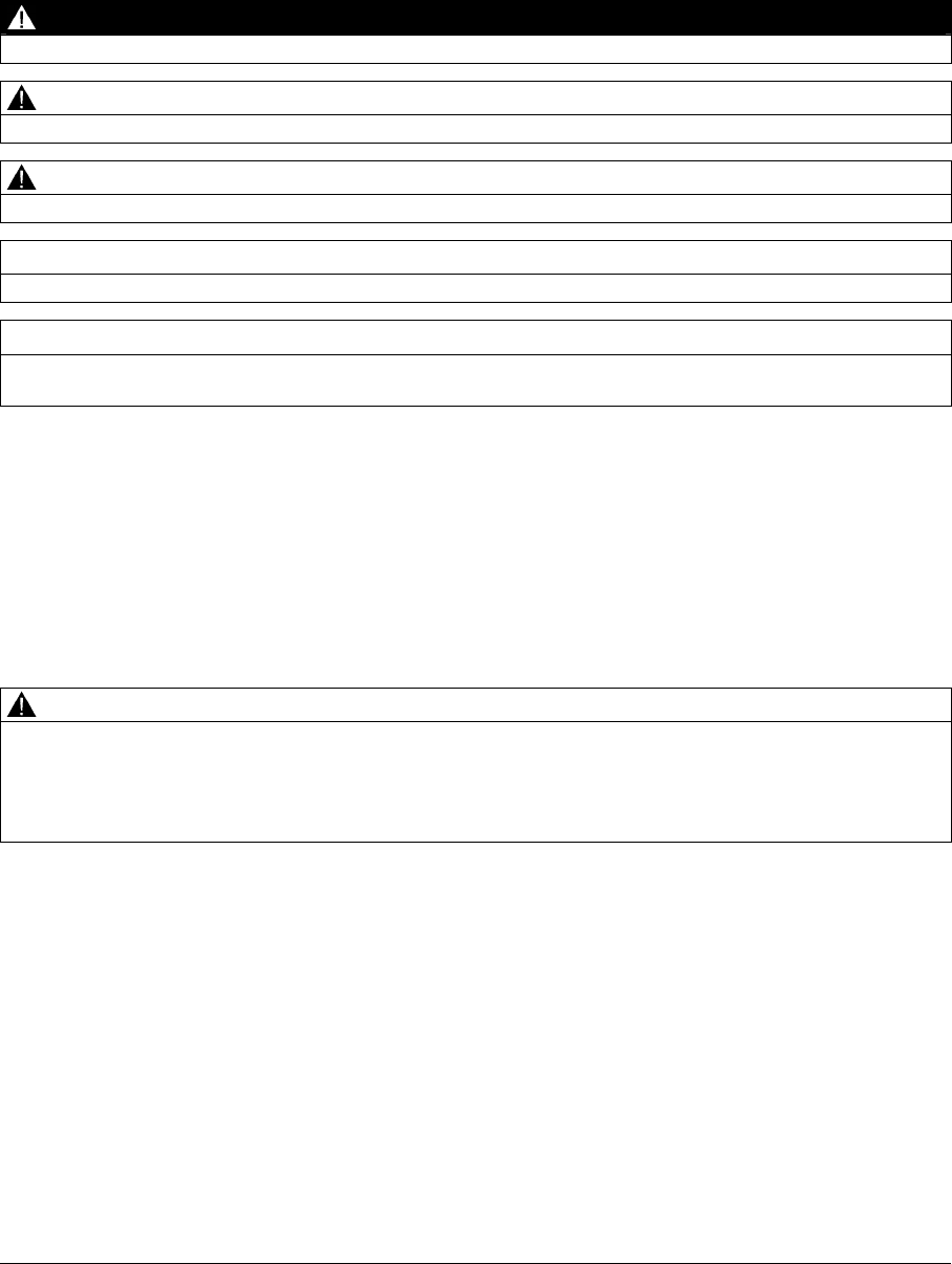
1.3 Wireless Teach Pendant F IWLAN
Front view and side view
① Rotary switch
② EMERGENCY STOP button
③ Illuminated pushbutton
④ Display with touch screen
⑤ LED display
⑥ Carrying strap
⑦ Safety bar
⑧ Membrane keyboard
⑨ Enabling button
⑩ Grip straps, left or right on the HMI device for securing
PRELIMINARY II
1.7.2010

Overview
1.3 Wireless Teach Pendant F IWLAN
Wireless Teach Pendant F IWLAN V2
Operating Instructions, 08/2010, A5E02453837-01 15
Wireless Teach Pendant F IWLAN is available in six models. The models are distinguished
by a different labeling on the membrane keyboard in the following languages:
● Japanese
● English
● French
● Chinese
● Czech
● Russian
The Wireless Teach Pendant F IWLAN works wirelessly on battery power, or it can be
mounted in the docking station.
Rear view
① Tray foot
② Nameplate
③ USB port with cover
④ Cover for connection compartment
⑤ Safety bars
⑥ Enabling button
⑦ Battery compartment cover
PRELIMINARY II
1.7.2010
Overview
1.4 Main rechargeable battery
Wireless Teach Pendant F IWLAN V2
16 Operating Instructions, 08/2010, A5E02453837-01
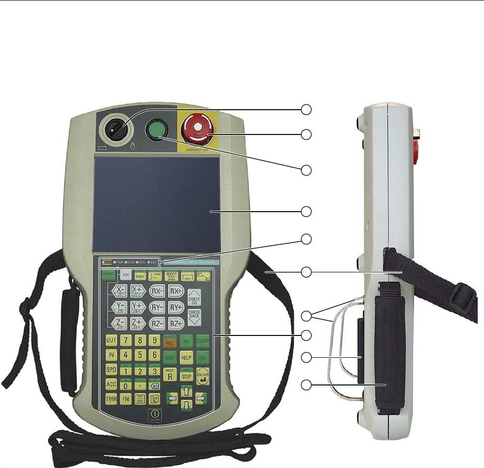
1.4 Main rechargeable battery
① Ribbon
② Nameplate
③ Button to switch on the LED display
④ Contact side
⑤ LED display
1.5 Accessories
The accessory can be ordered from the Internet at Industry Mall
(http://mall.automation.siemens.com).
● Main rechargeable battery
The main rechargeable battery supplies power to the HMI device.
Order number: 6AV6645-7BF26-0TA0
● Protective foil
The protective foil prevents the touch screen from becoming scratched or soiled.
The set contains 10 protective foils.
Order number: 6AV6645-7BF25-0TA0
● Memory card
Only use SD memory cards that have been tested and approved for used by Siemens AG
for the Wireless Teach Pendant F IWLAN.
Note
The MicroMemory card of the SIMATIC S7 controller is not suited for use with this HMI
device.
Order number: 6AV6671-1CB00-0TA0
● USB Flash drive for SIMATIC PC
The USB Flash drive for SIMATIC PC is a mobile data storage device with a high data
throughput, designed for industrial use.
PRELIMINARY II
1.7.2010

Overview
1.6 Equipment for HMI device and plant
Wireless Teach Pendant F IWLAN V2
Operating Instructions, 08/2010, A5E02453837-01 17
1.6 Equipment for HMI device and plant
1.6.1 Overview
The following devices are needed for the HMI device and for fail-safe operation of a plant:
● HMI device
– Docking station
– Charger
– Power supply unit
● Plant
– RFID tag
– Access point
– Signal lamp, optional
– Security systems, optional
The devices listed are not included in the scope of delivery of the HMI device. Order these
devices separately.
You can find order information on the Internet at Industry Mall
(http://mall.automation.siemens.com).
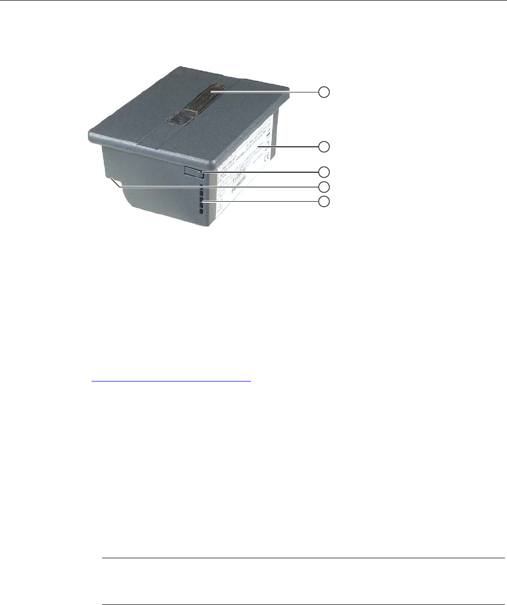
1.6.2 Docking station
The docking station is used for secure storage of the Wireless Teach Pendant F IWLAN.
When the Wirreless Teach Pendant F IWLAN rests in the docking station, the rechargeable
batteries. i.e. main battery and backup battery, will be charged.
The docking station is not included in the HMI device scope of delivery. The docking station
can be ordered with the order number 6AV6645-7BF28-0TA0.
PRELIMINARY II
1.7.2010
Overview
1.6 Equipment for HMI device and plant
Wireless Teach Pendant F IWLAN V2
18 Operating Instructions, 08/2010, A5E02453837-01
① Retention latch
② Mounting hole, left and right
③ Charge contact
④ Connection socket for the power unit (on the bottom)
Read the relevant documentation.
1.6.3 Charger°
The charger is used to charge and store the main batteries for the
Wireless Teach Pendant F IWLAN. You can charge one main battery in each of the two
charger sections.
NOTICE
Chargers suited for office environments only
If you use the charger in ambient conditions that do not correspond to an office
environment, malfunctions may occur.
Use the charger only in an office environment.
PRELIMINARY II
1.7.2010

Overview
1.6 Equipment for HMI device and plant
Wireless Teach Pendant F IWLAN V2
Operating Instructions, 08/2010, A5E02453837-01 19
The charger is not included in the HMI device scope of delivery. The charger is available
under the order number 6AV6645-7BF27-0TA0.
① Connection socket for the power unit
② Charging compartment
③ Contact strip
④ LED display
Read the relevant documentation.
1.6.4 Power supply unit
The power supply unit provides electricity to the docking station and charger. The power
supply unit can be used in 120 and 230 V AC power networks. The setting of the voltage
range takes place automatically. The output voltage is 24 VDC.
① "Power" LED
② Connecting cable
③ Power supply unit
④ Power supply cable
Order number: 6AV6671-5CN00-0TA0
PRELIMINARY II
1.7.2010
Overview
1.6 Equipment for HMI device and plant
Wireless Teach Pendant F IWLAN V2
20 Operating Instructions, 08/2010, A5E02453837-01
The power supply unit is provided with four power supply cables with plugs for the following
regions:
● Europe
● Asia
● North America
● United Kingdom of Great Britain and Northern Ireland
Read the relevant documentation.
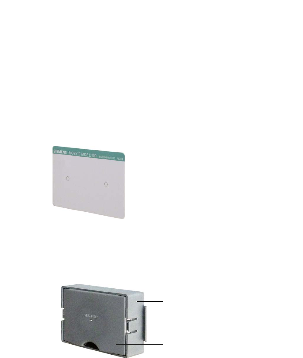
1.6.5 RFID tag
The RFID tag is required to log onto a machine. The RFID tag is a MDS D100 mobile data
storage unit.
Order number: 6GT2600-0AD10
The RFID tag includes the following accessories:
● Spacer
Order number: 6GT2190-0AA00
● Fixing pocket
Order number: 6GT2190-0AB00
$EVWDQGVKDOWHU
%HIHVWLJXQJVWDVFKH
PRELIMINARY II
1.7.2010
Overview
1.6 Equipment for HMI device and plant
Wireless Teach Pendant F IWLAN V2
Operating Instructions, 08/2010, A5E02453837-01 21
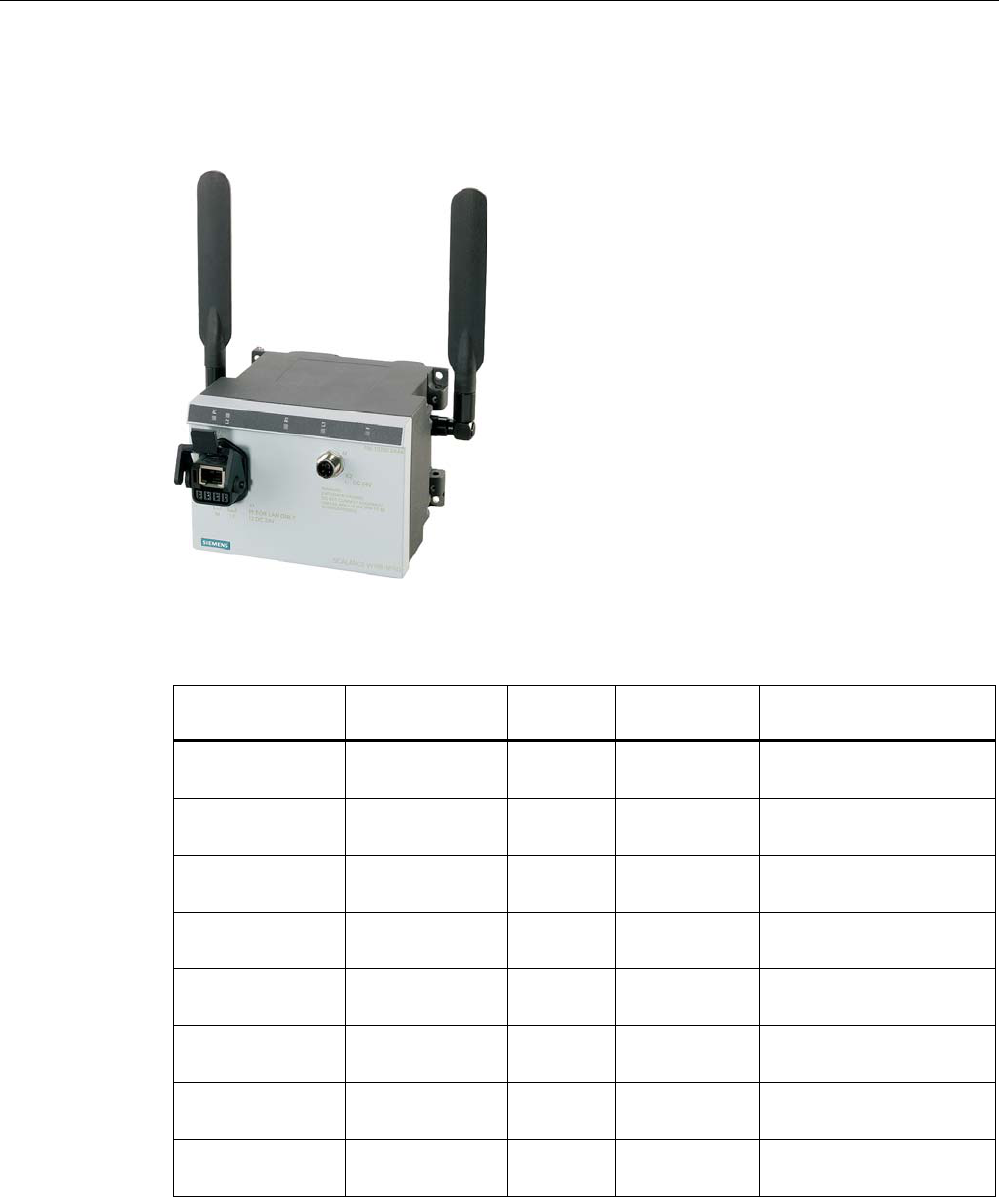
1.6.6 Access point
The access point is needed for the WLAN. The access point serves as a gateway between
the wireless and wired network.
To use the function iPCF-MC for Rapid Roaming, you need an access point with two radio
interfaces of the type SCALANCE W78x-2RR and firmware version V4.3.
We recommend the following access points for operation with the HMI device.
Designation Number of WLAN
interfaces
Antenna iPCF-MC /
Rapid roaming
Order number
SCALANCE
W784-1
1 External No 6GK5 784-1AA30-2AA0
6GK5 784-1AA30-2AB0 1)
SCALANCE
W786-1PRO
1 Internal No 6GK5 786-1BA60-2AA0
6GK5 786-1BA60-2AB0 1)
SCALANCE
W786-2RR
2 Internal Yes 6GK5 786-2BA60-6AA0
6GK5 786-2BA60-6AB0 1)
SCALANCE
W788-1PRO
1 External No 6GK5 788-1AA60-2AA0
6GK5 788-1AA60-2AB0 1)
SCALANCE
W788-2RR
2 External Yes 6GK5 788-2AA60-6AA0
6GK5 788-2AA60-6AB0 1)
SCALANCE
W786-1PRO
1 Internal No 6GK5 786-1BA60-2AA0
6GK5 786-1BA60-2AB0 1)
SCALANCE
W786-2RR
2 Internal Yes 6GK5 786-2BA60-6AA0
6GK5 786-2BA60-6AB0 1)
SCALANCE
W786-2RR
2 External Yes 6GK5 786-2AA60-6AA0
6GK5 786-2AA60-6AB0 1)
1) US version
Read the relevant documentation.
PRELIMINARY II
1.7.2010

Overview
1.7 Communication and approved controllers
Wireless Teach Pendant F IWLAN V2
22 Operating Instructions, 08/2010, A5E02453837-01
Additional access points and WLAN products are available in the Internet at: Industry Mall
(http://mall.automation.siemens.com)
1.7 Communication and approved controllers
Number of communication connections
Communication link Wireless Teach Pendant F IWLAN V2
Quantity, max. 6
Approved PLCs
NOTICE
Safety-related communication
A non-fail-safe controller cannot ensure safety-related communication.
A SIMATIC S7F PLC is required for safety-related communication.
Approved protocols
The HMI device uses the following protocols for communication with the controller:
● PROFINET
● PROFIsafe Mode V2.0
1.8 Software requirements
You need the following software for fail-safe operation:
● WinCC flexible 2008, SP2
● STEP 7 V5.4, as of SP2
● "SIMATIC S7 Distributed Safety V5.4" as of SP3 option package
● Customer-specific WinCC flexible 2008 SP2 add-on for the Wireless Teach Pendant F
IWLAN
PRELIMINARY II
1.7.2010

Overview
1.9 Supported WinCC flexible objects
Wireless Teach Pendant F IWLAN V2
Operating Instructions, 08/2010, A5E02453837-01 23
1.9 Supported WinCC flexible objects
The following tables contain the maximum number of objects you can use with the HMI
device in a project.
Note
The maximum number of multiple objects used simultaneously can affect the performance of
the active WinCC flexible project.
Alarms
Object Specification HMI device
Number of discrete alarms 4 000
Number of analog alarms 200
Length of the alarm text 80 characters
Number of tags in an alarm Max. 8
LEDs Alarm line, Alarm window,
Alarm view
Acknowledge error alarms individually Yes
Acknowledge several error alarms
simultaneously (group acknowledgment of
alarm groups)
16 alarm groups
Edit alarm Yes
Alarm
Alarm indicator Yes
ALARM_S Display S7 alarms Yes
Alarm buffer capacity 512 alarms
Simultaneously queued alarm events Max. 250
View alarm Yes
Delete alarm buffer Yes
Alarm buffer, retentive
Line-by-line printing of alarms Yes
Tags, values and lists
Object Specification HMI device
Tag Number 2 048
Limit value monitoring Input/Output Yes
Linear scaling Input/Output Yes
Text list Number 500 1)
Graphics list Number 400 1)
1) The maximum total of text and graphics lists is 500.
PRELIMINARY II
1.7.2010

Overview
1.9 Supported WinCC flexible objects
Wireless Teach Pendant F IWLAN V2
24 Operating Instructions, 08/2010, A5E02453837-01
HMI screens
Object Specification HMI device
Number 500
Fields per screen 200
Tags per screen 200
Complex objects per screen (for example
bars)
10
Screen
Template Yes
Recipes
Object Specification HMI device
Number 300
Data records per recipe 500
Entries per recipe 1 000
Recipe memory 64 KB
Recipe
Location1) Memory card
USB stick
Network drive
1) The number of recipe data records might be restricted by the capacity of the storage
medium.
Logs
NOTICE
Logging
The HMI device is suitable for logging small volumes of data. The use of a large circular log
has a negative effect on performance.
In order to log larger amounts of data, use segmented circular logs with multiple sequential
logs.
Object Specification HMI device
Number of logs 20
Number of partial logs in a segmented
circular log
400
Entries in each log including all partial logs 10 000
Filing format CSV with ANSI character set
Logs
Location1) Memory card
USB stick
Network drive
1) The number of entries in the log may be restricted by the capacity of the storage
medium.
PRELIMINARY II
1.7.2010

Overview
1.9 Supported WinCC flexible objects
Wireless Teach Pendant F IWLAN V2
Operating Instructions, 08/2010, A5E02453837-01 25
Safety
Object Specification HMI device
Number of user groups 50
Number of users 50
User administration
Number of authorizations 32
Infotexts
Object Specification HMI device
Length (no. of characters) 320
(depending on font)
For alarms Yes
For screens Yes
Infotext
For screen objects (for example for I/O
field, switch, button, invisible button)
Yes
Additional functions
Object Specification HMI device
Monitor setting Touch screen calibration
Brightness setting
Yes
Yes
Language change Number of languages 16
User-specific extension of the functionality Yes VBScript
Number of scripts 50
Graphics objects Vector and pixel graphics Yes
Trends Number 300
Task planner Number of tasks 48
Text objects Number 10 000
Direct keys PROFINET IO direct keys Yes
Device-specific functions
Object Specification HMI device
Main rechargeable battery Showing the battery charge Yes
WLAN quality Displaying WLAN quality Yes
Effective range (RFID) name Display effective range name Yes
PRELIMINARY II
1.7.2010
Overview
1.10 Configuration and process control phases
Wireless Teach Pendant F IWLAN V2
26 Operating Instructions, 08/2010, A5E02453837-01
Functions for RFID tag system
Configuration
Number of RFID tags in the project, maximum 127
Number of effective ranges in the project, maximum 127
Number of RFID tags per effective range, maximum 127
Number of HMI devices with logon authorization per effective
range,
when using F_FB_RNG_4 1), maximum
4 HMI devices
Number of devices with logon authorization per effective range,
when using F_FB_RNG_16 1), maximum
16 HMI devices
1) F_FB: Fail-safe function block
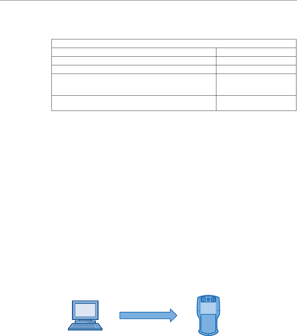
1.10 Configuration and process control phases
You must follow the phases below in order to use an HMI device in the system:
● Configuration phase
● Process control phase
Configuration phase
The configuration phase consists of the following operations:
● Create project
● Transferring a project
● Accept project – determine checksum
● Test project
● Simulate project
● Save project
&RQILJXUDWLRQ3&
6DIHW\UHODWHGSURMHFW
:LUHOHVV
7HDFK3HQGDQW),:/$1
Process control phase
The process control phase includes operation and monitoring of active production processes
with the HMI device. The HMI screens on the HMI device visualize the production process.
PRELIMINARY II
1.7.2010

Overview
1.11 Areas in the RFID tag system
Wireless Teach Pendant F IWLAN V2
Operating Instructions, 08/2010, A5E02453837-01 27
The following figure shows an example configuration of a plant control system which is
operated with a Wireless Teach Pendant F IWLAN.
6DIHW\UHODWHGGHYLFHV
6,0$7,&6)31'3
352),1(7,2FRQWUROOHU
6WDQGDUG+RVW3/&
352),1(7,2FRQWUROOHU
(7b6VWDWLRQ
ZLWK
,031
,2
352),1(7,2GHYLFH
:LUHOHVV7HDFK3HQGDQW
),:/$1
352),1(7,2GHYLFH
352),1(7
6&$/$1&(:
$FFHVV3RLQW
6,0$7,&6)
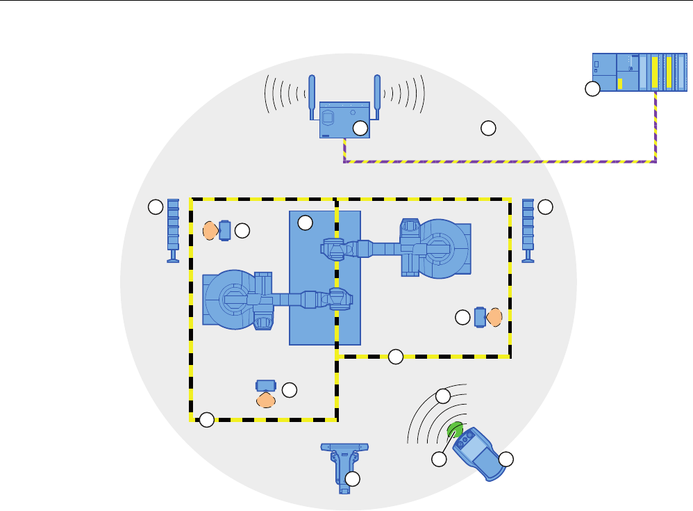
1.11 Areas in the RFID tag system
The following areas are available in a plant for fail-safe operation with RFID tag logon:
● WLAN for communication between a fail-safe controller and HMI device
● Effective range of the RFID tag for logging onto a machine
● RFID transmission and reception range of an HMI device for logging onto a machine
WLAN/iWLAN
Fail-safe controller and HMI device communicate over the radio cell of the access point. The
access point serves as a gateway between the wireless and wired network.
The WLAN or iWLAN in the plant is provided by at least one access point.
The figure below shows an example of the various areas.
PRELIMINARY II
1.7.2010
Overview
1.11 Areas in the RFID tag system
Wireless Teach Pendant F IWLAN V2
28 Operating Instructions, 08/2010, A5E02453837-01
352),VDIH
① SCALANCE W access point
② Cell of the access point
③ Fail-safe controller
④ Signal lamp
⑤ RFID tag with effective range
⑥ Plant
⑦ Protection zone limit of protection zone 1
⑧ Protection zone limit of protection zone 2
⑨ WLAN of the HMI device
⑩ Docking station
⑪ RFID transmission and reception range of the HMI device
⑫ HMI device
RFID tag with effective range
The RFID tag is a storage device for a configured ID. The ID of the RFID tag is required for a
HMI device to log onto a machine. The RFID transmission and reception range of the HMI
device is brought into the effective range of the RFID tag in order to log on.
A signal lamp indicates whether an HMI device is logged onto a machine.
PRELIMINARY II
1.7.2010

Overview
1.12 Rapid roaming
Wireless Teach Pendant F IWLAN V2
Operating Instructions, 08/2010, A5E02453837-01 29
Protection zone
The protection zone is the area in the plant in which one or more machines are operated in
fail-safe mode. The protection zone of the plant is demarcated by a security system and
organizational measures.
The protection zone is not an object that can be configured.
Security system and organizational measures
The security system consists of one or more technical protection devices for the protection
zone, e.g.:
● Mesh fence with access
● Light barrier
● Contact pressure mat
The security system can be controlled by a safety program, such as a program for robot
control conforming to a robotics directive.
1.12 Rapid roaming
The wireless range of an iWLAN system can be expanded through the use of multiple
access points. If an HMI device moves beyond the range of a SCALANCE W78x and into the
range of another SCALANCE W78x, the wireless connection remains intact (roaming).
Capabilities provided by iPCF
In the industrial environment, there are applications that require deterministic behavior for a
large number of participants and high data throughput in a cell. In addition, deterministic
behavior is required for cell cross-overs with handover times of less than 100 milliseconds.
The iPCF extension (Industrial Point Coordination Function) was developed to meet these
requirements.
iPCF ensures that all data traffic runs in coordinated fashion in a wireless cell, controlled by
the access point. It also optimizes the throughput with a high number of participants by
avoiding collisions. iPCF also facilitates very fast cell changes.
Special features provided by iPCF-MC
iPCF-MC was designed to enable free-moving participants to exploit the special advantages
provided by iPCF, which allows communication independent of an RCoax line or directional
antennas. With iPCF-MC, the client looks for potentially suitable access points even when it
is receiving iPCF queries from the access point and the existing connection to an access
point is functioning correctly. This makes it possible to switch to another access point very
quickly if it becomes necessary. Unlike iPCF, with iPCF-MC the handover times do not
depend on the number of radio channels in use.
PRELIMINARY II
1.7.2010
Overview
1.12 Rapid roaming
Wireless Teach Pendant F IWLAN V2
30 Operating Instructions, 08/2010, A5E02453837-01
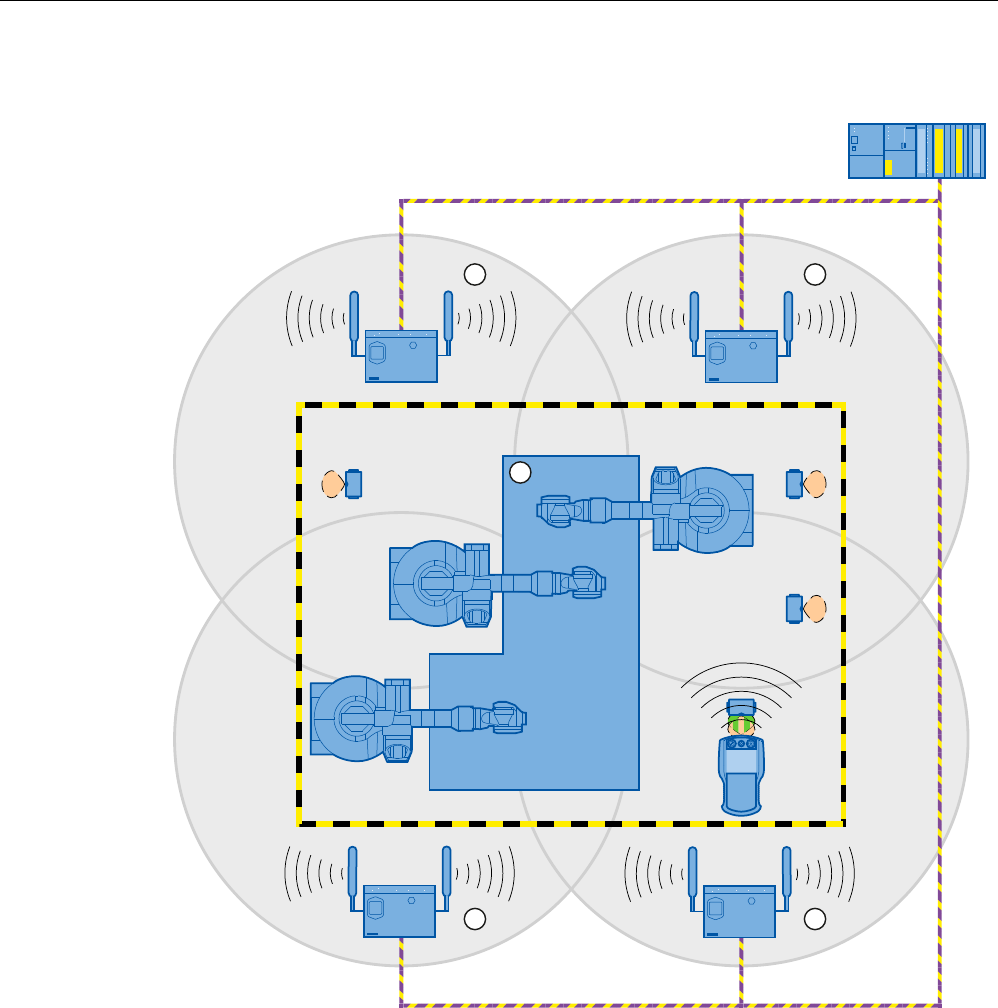
The following figure shows an example of a plant with four WLAN areas.
352),VDIH
① Radio cell of access point 1
② Radio cell of access point 2
③ Radio cell of access point 3
④ Radio cell of access point 4
⑤ Plant
For rapid roaming with iPCF-MC, you will require a suitable access point – see section
"Access point (Page 21)".
We always recommend that you activate iPCF or iPCF-MC mode for PNIO communication.
PRELIMINARY II
1.7.2010

Overview
1.12 Rapid roaming
Wireless Teach Pendant F IWLAN V2
Operating Instructions, 08/2010, A5E02453837-01 31
For stable PNIO communication, a WLAN client should be located at all times in a radio cell
with a signal strength > 60% or > -65 dBm. This can be checked by switching the various
segments on and off.
This does not mean that the client needs to change over at a signal strength < 60% or < -65
dBm. Make sure that a segment is available with a sufficiently powerful signal.
Limitations due to iPCF-MC
iPCF-MC is an in-house development of the Siemens AG that will only work with participants
in which iPCF-MC has been installed.
Operating principle of iPCF-MC
iPCF-MC uses both radio interfaces of the access point differently: One interface works as
management interface and sends a beacon every five milliseconds. The other interface
transmits the user data.
The following requirements have to be met to use iPCF-MC:
● All "RR" versions of the SCALANCE W-700 access points with at least two WLAN
interfaces can be used as access point. The HMI device and all SCALANCE W-700 "RR"
versions are suited as clients.
● You have to operate the management interface and the data interface in the same
frequency band; they also have to match in their radio coverage. iPCF-MC will not work if
both radio interfaces are equipped with directional antenna the cover different areas.
● The management inferfaces of all access points that a client is to access must use the
same channel. A client will only scan this one channel to find all available access points.
● You cannot use the transmission method to IEEE 802.11h for the management interface.
802.11h is possible for the data interface.
PRELIMINARY II
1.7.2010

Overview
1.13 Terms for fail-safe operation
Wireless Teach Pendant F IWLAN V2
32 Operating Instructions, 08/2010, A5E02453837-01
1.13 Terms for fail-safe operation
Fail-safe automation system
A fail-safe automation system is required in a plant with high safety requirements.
In an EMERGENCY STOP, the fail-safe automation system brings the plant to a safe
operating state regardless of the situation. Shutdown of the plant therefore does not pose a
danger to people or the plant.
Fail-safe operation
The HMI device registers signals from the EMERGENCY STOP button and the enabling
button during fail-safe operation. The controller and the HMI device communicate via
PROFIsafe.
Configuration of the safety functions in STEP 7 with the "SIMATIC S7 Distributed Safety"
add-on package can achieve fail-safe operation according to SIL 3 or Performance Level e
and Category 4 for the HMI device.
Integration and removal
● Integrating
Integration means to establish safety-related communication between the HMI device and
the fail-safe controller via PROFIsafe.
The EMERGENCY STOP button is enabled in integrated operating mode.
● Removing
Removal means to intentionally stop safety-related communication between the HMI
device and the fail-safe controller via PROFIsafe.
Logging on the HMI device
The HMI device must be logged onto a machine in order to operate the machine after
integration in fail-safe operation with the enabling button. The logon is performed with an
RFID tag.
Logging off an HMI device
Logging off an HMI device from a machine terminates fail-safe operation with the enabling
button.
● Forced logoff
If the security system is triggered, for example by the operator leaving the protection zone
without logging off, a forced logoff is performed by the machine. The HMI device revokes
the operator authorization for the enabling button. The operator is prompted to confirm
the "Forced logoff" dialog.
● Automatic logoff in the event of a communication error
PRELIMINARY II
1.7.2010

Overview
1.13 Terms for fail-safe operation
Wireless Teach Pendant F IWLAN V2
Operating Instructions, 08/2010, A5E02453837-01 33
If a communication error occurs, the HMI device is removed from the safety-related
communication. The HMI device is automatically logged off the machine. The fail-safe
controller brings the plant to a safe operating state.
Shutdown response of the plant
● The following shutdown response of the plant applies regardless of whether or not the
HMI device is logged onto a machine.
– EMERGENCY STOP
EMERGENCY STOP is a procedure that is intended to stop a process or movement
associated with danger in accordance to EN 60204-1, Appendix D. An EMERGENCY
STOP immediately stops all parts of the plant controlled by the fail-safe controller via a
safety program. The EMERGENCY STOP button is always enabled when there is
PROFIsafe communication between HMI device and fail-safe controller, i.e. when the
HMI device is integrated in the PROFIsafe communication.
– Global rampdown
A global rampdown is the intentional stopping of the plant. The global rampdown is
independent of the area.
The global rampdown is triggered by the fail-safe controller, for example, if an error
occurs with an HMI device integrated in the PROFIsafe communication.
● The following shutdown response of the plant applies when the HMI device is logged onto
a machine.
– Local rampdown
A local rampdown is the intentional stopping of a plant section by the fail-safe
controller. The local rampdown is triggered, for example, when the operator leaves the
protection zone without logging off via a security system.
– Shutdown
The shutdown is triggered when the F-CPU has detected a communication error with
an HMI device that is logged onto a machine. Shutdown is the immediate stop of all
machinery being operated in fail-safe mode.
Communication error
A communication error occurs when the communication between HMI device and fail-safe
controller is interrupted. Additional information is available in the section "Communication
error for the integrated HMI device (Page 256)".
PRELIMINARY II
1.7.2010

Overview
1.13 Terms for fail-safe operation
Wireless Teach Pendant F IWLAN V2
34 Operating Instructions, 08/2010, A5E02453837-01
PRELIMINARY II
1.7.2010

Wireless Teach Pendant F IWLAN V2
Operating Instructions, 08/2010, A5E02453837-01 35
Safety instructions and standards 2
2.1 Safety instructions
WARNING
Injury or material damage
If you do not exactly adhere to the safety regulations and procedural instructions contained
in this manual, hazards may arise and safety features be rendered ineffective. This can
result in personal injuries or material damage.
Closely follow closely the safety regulations and procedural instructions in each situation.
Observe the regulations for safety and accident prevention applicable to your application in
addition to the safety instructions given in this manual.
Project security
WARNING
Injury or material damage
The configuration engineer for plant control must take precautions to ensure that an
interrupted program will be correctly integrated again after communication failures, voltage
dips or power outages.
A dangerous operating state must not be allowed to occur - not even temporarily - during
the entire execution of the control program, even during a troubleshooting.
Safety during commissioning and operation
WARNING
Installation according to the instructions
Commissioning of the HMI device is prohibited until it has been absolutely ensured that the
machine to be operated with the HMI device complies with Directive 2006/42/EC.
Verify before commissioning that the provisions of Directive 2006/42/EC are fulfilled.
PRELIMINARY II
1.7.2010

Safety instructions and standards
2.2 Approvals
Wireless Teach Pendant F IWLAN V2
36 Operating Instructions, 08/2010, A5E02453837-01
Safety during operation
WARNING
HMI device failure
A strong shock or impact can impede the functionality of the HMI device.
After a strong mechanical action, ensure the HMI device and the safety-related parts are in
working order.
Danger of injury
Manual movements controlled with the HMI should only be executed in conjunction with the
enabling buttons and at reduced velocity.
Exclusive operating right
The simultaneous operation of the plant with multiple HMI devices is not allowed.
Prevent simultaneous operation through the appropriate configuration.
Note
The function of the EMERGENCY STOP button must be checked periodically.
High-frequency radiation, for example from cellular phones, can lead to undesirable
operating states in a plant.
2.2 Approvals
Note
The following overview shows possible approvals.
The only valid approvals for the HMI device, the docking station, the power supply module
and the RFID tag are those shown on the label on the rear panel.
CE approval
The HMI device, the docking station, the power supply and the RFID tag conform to the
European standards for programmable logic controllers as published in the official journals of
the European Union:
● 2004/108/EC "Electromagnetic Compatibility" (EMC Directive)
● 1999/5/ECG "Directive of the European Parliament and of the Council from March 9,
1999 relating to Radio Equipment and Telecommunications Terminal Equipment and the
Mutual Recognition of their Conformity"
PRELIMINARY II
1.7.2010

Safety instructions and standards
2.2 Approvals
Wireless Teach Pendant F IWLAN V2
Operating Instructions, 08/2010, A5E02453837-01 37
EC Declaration of Conformity
The EC Declarations of Conformity are available to the relevant authorities at the following
address:
Siemens AG
Industry Sector
I IA AS RD ST
PO Box 1963
92209 Amberg
Germany
UL approval
Underwriters Laboratories Inc. in accordance with:
● UL 60950 (Safety of Information Technology Equipment)
● CAN/CSA-C22.2 No. 60950-00 (Safety of Information Technology Equipment)
Requirements of the approval are only met if the device is operated with the main
rechargeable battery or in stationary mode in the docking station.
Marking for Australia
The HMI device, the docking station, the power supply module and the RFID tag meet
requirements to AS/NZS 2064 (Class A).
Wireless approval
The national approvals for the HMI device are listed on the back of the device and in the
product information for "Wireless Teach Pendant F IWLAN" in the Internet
(http://support.automation.siemens.com/WW/view/en/30360848/133300).
Requesting certificates
A copy of the certificates and associated reports is available upon request from the following
address:
Siemens AG
Industry Sector
I IA AS RD ST
PO Box 1963
92209 Amberg
Germany
PRELIMINARY II
1.7.2010

Safety instructions and standards
2.3 Standards on operating safety
Wireless Teach Pendant F IWLAN V2
38 Operating Instructions, 08/2010, A5E02453837-01
2.3 Standards on operating safety
The HMI device meets the following standards for use in a plant:
Standard Title Version
EN 12417 Machine Tools - Safety - Machining Centres 01.07.2009
EN 60950 Information Technology Equipment (General
Requirements)
01.11.2006
UL 60950 Safety of Information Technology Equipment 11.12.2000
CAN/CSA-C22.2
No. 60950-00
Safety of Information Technology Equipment 01.12.1990
EMC testing The values of the EMC test for the HMI device conform to the following standards:
Standard Title Version
EN 61000-6-2 EMC – Part 6-2: Generic standards - Immunity for
industrial environments
01.05.2006
EN 61000-6-4 EMC – Part 6-4: Generic standards - Emission
standard for industrial environments
01.11.2007
DIN EN 50360 Product standard to demonstrate the compliance of
mobile phones with the basic restrictions related to
human safety in electromagnetic fields (300 MHz to 3
GHz)
01.05.2002
DIN EN 50371 Generic standard to demonstrate compliance of low
power electronic and electrical apparatus with the
basic restrictions related to human exposure to
electromagnetic fields (10 MHz to 300 GHz)
01.11.2002
DIN EN 61131-2 Programmable Logic Controllers – Part 2: Equipment
requirements and testing
01.01.2009
DIN EN 300440-1 Electromagnetic compatibility and radio spectrum
matters
01.08.2009
DIN EN 301893 Broadband Radio Access Networks (BRAN) 01.05.2009
EN 50385 Product standard to demonstrate the compliance of
radio base stations and fixed terminal stations for
wireless telecommunication systems
01.05.2003
EN 300328 Electromagnetic compatibility and radio spectrum
matters
01.03.2009
EN 300330 Electromagnetic compatibility and radio spectrum
matters (ERM)
01.08.2006
EN 301489-1 Electromagnetic compatibility and radio spectrum
matters (ERM)
01.01.2010
EN 301489-3 Electromagnetic compatibility and radio spectrum
matters (ERM)
01.01.2003
EN 301489-17 Electromagnetic compatibility and radio spectrum
matters
01.07.2009
FCC OET 65, RSS-210, Part 15247, 15407 radio
authorization
FCC RFID 15225, RSS 210
PRELIMINARY II
1.7.2010

Safety instructions and standards
2.4 Operating conditions
Wireless Teach Pendant F IWLAN V2
Operating Instructions, 08/2010, A5E02453837-01 39
TÜV
The TÜV confirms that the HMI device satisfies the requirements of the following standards
with regard to its safety functions.
Standard Title Version
DIN EN 60204-1 Safety of machinery – Electrical equipment of
machines – Part 1: General Requirements
01.10.2009
DIN IEC 62061 Safety of machinery – Functional safety of electrical,
electronic and programmable control systems for
machinery
01.04.2009
IEC 61508-1 to 4 Safety Integrity Level 3 01.01.2005
ISO 13850 Safety of machinery - EMERGENCY STOP -
Principles for design
01.01.2009
ISO 13849-1 Performance Level e and Category 4 01.09.2009
Additional measurements
Additional measurements were made for:
● Japan
– Table/Annex No 43,44,45 – Test Method for Radio Equipment mentioned in
Certification Regulations Article, Item 19, 19-2, 19-3 and 19-3-2
– Table/Annex No 47 – Test Method for Radio Equipment mentioned in Certification
Regulations Article, Item 19-5 and 19-11
– RFID – ARIB STD T-82
● Taiwan
– LP0002
2.4 Operating conditions
The national approvals for the HMI device are listed on the back of the device and in the
product information for "Wireless Teach Pendant F IWLAN V2" in the Internet
(http://support.automation.siemens.com/WW/view/en/30360848/133300).
NOTICE
Wireless control device
A wireless control device may cause interference.
If a wireless control device is used, the following must be ensured:
That other systems at the site are not disturbed by the wireless control device
That other systems at the site do not disturb the wireless control device
PRELIMINARY II
1.7.2010

Safety instructions and standards
2.5 Risk analysis of the plant
Wireless Teach Pendant F IWLAN V2
40 Operating Instructions, 08/2010, A5E02453837-01
Use in industry
The HMI device is designed for industrial use. For this reason, the following standards are
met:
● Interference emission requirements, paragraph 7.3, DIN EN 60947-1, Environment A
● Interference immunity requirements DIN EN 61326
Residential use
NOTICE
Interference to radio and TV reception
The HMI device is not suitable for use in residential areas: Operation of HMI devices in
residential areas can cause interference to radio and television reception.
If the HMI device is used in a residential area, you must take measures to achieve Limit
Class B conforming to EN 55016 for RF interference.
To achieve radio interference suppression class B, for example, install filters in power supply
lines.
Individual acceptance is required.
2.5 Risk analysis of the plant
The following rules apply to the risk analysis of the plant:
● ISO 12100-1 and ISO 12100-2, General design guidelines for machines
● ISO 13849-1, Safety of machinery - Safety-related parts of control systems - General
principles for design
● ISO 14121-1, Safety of machinery – Risk assessment – Part 1: Principles
These considerations result in a performance levels a to e in accordance with ISO 13849-1,
which dictate how the safety-related parts of the system must be furnished.
The safety-related parts of the HMI device meet:
● SIL 3 in accordance with IEC 61508
● Performance level e and Category 4 in accordance with ISO 13849-1
Take the plant configuration as a whole into consideration in the risk analysis and not just the
separate sections. For additional information on risk analysis and risk mitigation, refer to the
"Safety Technology in SIMATIC S7" system manual
(http://support.automation.siemens.com/WW/view/en/12490443).
See also
Safety-related operator controls (Page 88)
PRELIMINARY II
1.7.2010

Safety instructions and standards
2.6 Safety functions of the EMERGENCY STOP button
Wireless Teach Pendant F IWLAN V2
Operating Instructions, 08/2010, A5E02453837-01 41
2.6 Safety functions of the EMERGENCY STOP button
The EMERGENCY STOP button on the HMI device brings about a safety-related stop of the
plant in accordance with IEC 60204-1, Section 9.2.5.3. You can implement a Category 0, 1,
or 2 stop function in accordance with IEC 60204-1, Section 9.2.2. The stop function category
must be selected on the basis of a risk assessment.
The following requirements must be met in order to render the EMERGENCY STOP button
effective:
● The HMI device must be operated in the docking station or with the main rechargeable
battery.
● A project is running on the HMI device.
● The HMI device must be integrated in the safety program of the F-CPU.
If these prerequisites are satisfied the following applies:
● The "SAFE" LED on the HMI device is lit.
● The EMERGENCY STOP button is enabled.
As soon as the PROFIsafe communication between the HMI device and controller is
established within the WLAN range, the EMERGENCY STOP button on the HMI device
becomes active. The EMERGENCY STOP button is enabled within the WLAN regardless of
whether or not the HMI device is logged onto a machine.
WARNING
EMERGENCY STOP button not available
The EMERGENCY STOP button on the HMI device may not used as a replacement for a
permanently-wired EMERGENCY STOP or EMERGENCY OFF on the machine.
Install stationary EMERGENCY STOP buttons that will be available at all times on the
configured system.
EMERGENCY STOP button not enabled
If a communication error triggers a global rampdown, the EMERGENCY STOP button will
no longer be available on the affected HMI device.
You have the option of interconnecting the "Global Rampdown" signal so that an
EMERGENCY STOP is triggered.
EMERGENCY STOP button out of service when HMI device is removed
If the HMI device is not integrated in the safety program of the F-CPU, the EMERGENCY
STOP button will be out of service.
To avoid confusion between HMI devices with enabled and disabled EMERGENCY STOP
buttons during an emergency, only one integrated HMI device should be freely accessible.
If an HMI device is not integrated and not in use, store the HMI device in a location with
protected access.
Category 0 or 1 Stop
If a Category 0 or 1 stop circuit is implemented, the stop function must be effective
regardless of the operating mode. A Category 0 stop must have precedence. Release of
the EMERGENCY STOP button must not cause a hazardous situation (see also EN 60204-
1, Section 9.2.5.3).
The stop function is not to be used as a replacement for safety equipment.
PRELIMINARY II
1.7.2010

Safety instructions and standards
2.7 Safety functions of the enabling mechanism
Wireless Teach Pendant F IWLAN V2
42 Operating Instructions, 08/2010, A5E02453837-01
Note
The EMERGENCY STOP button is evaluated when the HMI device is integrated in the
safety program of the F-CPU. The EMERGENCY STOP button can be triggered
unintentionally in the following situations:
If the HMI device falls down
When opening one of the coverings on the rear of the HMI device
2.7 Safety functions of the enabling mechanism
In a numerically controlled system, the "Special mode" operating mode requires an enabling
mechanism. The enabling mechanism is comprised of two enabling buttons mounted on both
sides of the HMI device.
Special mode
During special mode, safety has to be ensured in a different manner than in automatic mode.
During special mode, personnel enter danger zones of the plant in which controlled
movements must be possible.
Depending on the risk assessment of the plant, movement needs to occur at reduced speed
for special mode. Movement of the plant parts should only be possible when the enabling
mechanism is activated. The operator must be accordingly qualified and know details of use
in accordance with safety regulations.
Safety instructions
The safety-related parts of the controller for speed reduction and those for the enabling
mechanism are designed in such a way that they satisfy the requirements for the safety
category as determined by the risk assessment.
The operating principles of enabling devices are described in EN 60204. Through the
findings from accident investigations and the existence of technical solutions, the 3-stage
enabling button became state of the art. Positions 1 and 3 of the enabling button are Off
functions. Only the middle position allows the enabling function. EN 60204-1 is identical to
IEC 60204-1, whereby the 3-stage enabling button is gaining international importance.
PRELIMINARY II
1.7.2010

Safety instructions and standards
2.7 Safety functions of the enabling mechanism
Wireless Teach Pendant F IWLAN V2
Operating Instructions, 08/2010, A5E02453837-01 43
The Stop category of the enabling device must be selected on the basis of a risk assessment
and correspond to a Category 0 or 1 Stop.
WARNING
Injury or material damage
Enabling buttons should only be used when the following applies for the person activating
the enabling button:
The person can see the danger zone.
The person is capable of recognizing personal injury hazards in good time.
The person is capable of taking immediate measures to avoid danger.
The only person allowed to remain in the danger zone is the person who is activating the
enabling button.
Commands for unsafe conditions are not permitted to be issued with one enabling button
alone. To accomplish this, a secondary, conscious start command using a button on the
HMI device is required.
NOTICE
Risk from improper use
An enabling button can be fixed without permission.
To avoid the risk of unauthorized fixation, fully press both enabling buttons each time the
project starts. Release the enabling buttons.
Note
The enabling button only has an effect when the HMI device is logged onto a machine and
the "RNG" LED on the HMI device is lit.
See also
Risk analysis of the plant (Page 40)
PRELIMINARY II
1.7.2010

Safety instructions and standards
2.8 Electromagnetic compatibility
Wireless Teach Pendant F IWLAN V2
44 Operating Instructions, 08/2010, A5E02453837-01
2.8 Electromagnetic compatibility
The HMI device, docking station, power supply and RFID tag meet the requirements of the
EMC regulations pertaining to the European domestic market and more. The enhanced
testing and limit value levels defined by CDV 61326-3-1/Ed. 1 have been taken into account
during the type test
EMC-compliant installation
Conditions for fault-free operation include EMC-conform assembly of the docking station and
RFID tag, as well as the use of interference-proof cables. The following documents also
apply to the installation of the docking station:
● Description "Directives for interference-free installation of PLCs"
(http://support.automation.siemens.com/WW/view/de/1064706), German
● System manual "Basics on Setting up an Industrial Wireless LAN"
(http://support.automation.siemens.com/WW/view/en/9975764)
Pulse-shaped disturbance
The following table shows the electromagnetic compatibility of modules with regard to pulse-
shaped interference. The table applies to the docking station, with and without an attached
HMI device.
Pulse-shaped disturbance Tested with Degree of
severity
Electrostatic discharge
in accordance with IEC 61000-4-
2
Air discharge: 8 kV
Contact discharge: 6 kV
3
Burst pulses
(high-speed transient
interference)
in accordance with IEC 61000-4-
4
2 kV supply line 3
An external safety circuit is required for the "Surge immunity test according to IEC 61000-4-
5". The safety circuit is described in the Installation manual "Automation System S7-300 –
Installation" (http://support.automation.siemens.com/WW/view/en/15390415), section
"Lightning and overvoltage protection".
Pulse-shaped disturbance Tested with Degree of
severity
Asymmetrical coupling 2 kV power cable
DC voltage with protective elements
3
Symmetrical coupling 1 kV power cable
DC voltage with protective elements
3
PRELIMINARY II
1.7.2010

Safety instructions and standards
2.8 Electromagnetic compatibility
Wireless Teach Pendant F IWLAN V2
Operating Instructions, 08/2010, A5E02453837-01 45
Sinusoidal interference
The following table shows the EMC behavior of the modules with respect to sinusoidal
interference.
The table applies to the HMI device, docking station and power supply.
Sinusoidal interference Test values Degree of
severity
HF radiation (in electromagnetic
fields) in accordance with
IEC 61000-4-3
80% amplitude modulation at 1 kHz
Up to 10 V/m in the 80 MHz to 1 GHz range
Up to 10 V/m in the 1.4 GHz to 2 GHz range
Up to 1 V/m in the 2 GHz to 2.7 GHz range
3
RF interference current on
cables and cable shielding
conforming to IEC 61000-4-6
Test voltage 10 V, with 80% amplitude modulation
of 1 kHz in the 9 kHz to 80 MHz range
3
Emission of radio interference
The following table shows the interference emissions from electromagnetic fields in
accordance with EN 55016, Limit Value Class A, Group 1, measured at a distance of 10 m.
30 to 230 MHz < 40 dB (V/m) quasi-peak
230 to 1 000 MHz < 47 dB (V/m) quasi-peak
Note
Before you connect the HMI device to the public electrical network, ensure that it is
compliant with Limit Value Class B in accordance with EN 55022.
PRELIMINARY II
1.7.2010

Safety instructions and standards
2.9 Transport and storage conditions
Wireless Teach Pendant F IWLAN V2
46 Operating Instructions, 08/2010, A5E02453837-01
2.9 Transport and storage conditions
The shipping conditions of this HMI device exceed requirements in accordance with IEC
61131-2. The following specifications apply to devices that are shipped and stored in the
original packaging.
● The mechanical conditions are compliant with IEC 60721-3-2, Class 2M2.
The following table shows the transport and storage conditions for the HMI device, docking
station, power supply unit and RFID tag.
Type of condition Permitted range
Drop test (in transport package) ≤ 1 m
Temperature –20 to +60 °C
Atmospheric pressure 1140 hPa to 660 hPa,
corresponds to an elevation of –1000 to 3500 m
Relative humidity Applies to HMI device:
10 to 90%, without condensation
Applies to docking station:
35 to 85%, without condensation
Sinusoidal vibration in accordance with
IEC 60068-2-6
5 Hz to 9 Hz: 3.5 mm
9 Hz to 500 Hz: 9.8 m/s2
Shock in accordance with IEC 60068-2-29 250 m/s2, 6 ms, 1000 shocks
NOTICE
Equipment failure
Moisture in the form of condensation on or in the device is formed:
When transporting a device at low temperatures
Under extreme temperature variations
Moisture and condensation lead to malfunction.
Bring the device to room temperature before operating.
Condensation
When condensation is on the device, do not expose the HMI device to direct radiation from
a heater.
If condensation has developed, wait approximately 4 hours until the HMI device has dried
completely before switching it on.
The following points must be adhered to in order to ensure a fault-free and safe operation of
the HMI device:
● Proper transportation and storage
● Proper installation and mounting
● Careful operation and maintenance
The warranty for the HMI device will be deemed void if these stipulations are not heeded.
PRELIMINARY II
1.7.2010

Wireless Teach Pendant F IWLAN V2
Operating Instructions, 08/2010, A5E02453837-01 47
Planning the use 3
3.1 Checklist
Perform the following tasks when planning fail-safe operation. Confirm each task by
checking it off in the following list.
Task Additional information Check
Check the ambient conditions at the
site.
Operating conditions (Page 48)
Plan access routes to the plant. –
Plan operator locations at the plant
where WLAN will be needed.
WLAN properties (Page 51)
Plan the WLAN.
Determine the installation locations
for the access points based on this.
Special programs are available for
planning the WLAN.
We strongly recommend you check
the local wireless conditions before
beginning start-up.
System manual "Basics on Setting up an Industrial
Wireless LAN"
(http://support.automation.siemens.com/WW/view/en/
9975764)
"SINEMA E" planning program
(http://www.siemens.com/sinema)
Guideline for the Use of Industrial Wireless LAN in a
PROFINET IO Environment
(http://support.automation.siemens.com/WW/view/en/
31938420)
Plan for information security. Planning information security (Page 59)
Plan the configuration of the
PROFINET and PROFIsafe
communication.
System manual "Communication with SIMATIC"
(http://support.automation.siemens.com/WW/view/en/
25074283)
Programming and operation manual "S7 Distributed
Safety - Configuring and Programming"
(http://support.automation.siemens.com/WW/view/en/
22099875)
Plan the installation locations for the
RFID tags.
Planning an installation location for RFID tags
(Page 54)
Plan the installation location and
clearance for the docking station.
Planning the installation location and clearance of the
docking station (Page 56)
Plan the location for the signal
lamps.
Planning the installation location of signal lamps
(Page 57)
PRELIMINARY II
1.7.2010

Planning the use
3.2 Operating conditions
Wireless Teach Pendant F IWLAN V2
48 Operating Instructions, 08/2010, A5E02453837-01
3.2 Operating conditions
Mechanical and climatic ambient conditions
The HMI device is designed for use in a location protected from the effects of the weather.
The ambient conditions meet the requirements for DIN IEC 60721-3-3:
● Mechanical requirements according to class 3M3
The following table applies to the HMI device and docking station.
● Climatic requirements according to class 3K3
Use with additional protective measures
You may only use the HMI device at the following locations with additional protective
measures:
● In locations with a high degree of ionizing radiation
● In locations with difficult operating conditions, for example due to:
– Corrosive vapors, gases, oils or chemicals
– Electrical or magnetic fields of high intensity
● In systems that require special monitoring, for example:
– Elevators
– Systems in especially hazardous rooms
Damping shock and vibration
If the HMI device is subjected to impermissibly strong shocks or vibrations, you must take
appropriate measures to reduce amplitudes or acceleration. In such situations, use vibration
damping or vibration absorber systems for the HMI device and accessories.
NOTICE
Setting down the HMI device
If you place the HMI device on a surface with a high natural frequency, malfunctions may
occur as a result.
Do not place the HMI device on a surface with a high natural frequency.
PRELIMINARY II
1.7.2010

Planning the use
3.2 Operating conditions
Wireless Teach Pendant F IWLAN V2
Operating Instructions, 08/2010, A5E02453837-01 49
Testing mechanical ambient conditions
The following table provides information on the type and scope of tests for mechanical
ambient conditions performed for the HMI device.
Test Physical variable Value
Vibration 1 octave/min
10 cycles per axis
5 to 8.4 Hz:
Deflection 3.5 mm
Vibrations
IEC 60068-2-6
Test Fc Frequency band
8.4 to 150 Hz
Vibration acceleration 9.8 m/s
Shock form Half sine
Shock amplitude 15 g
Shock duration 11 ms
Shock
IEC 60068-2-27
Number of shocks 3 per axis
Impact
IEC 60068-2-75
Impact stress 1 Nm, once
With an impact test device similar to
DIN VDE 0740, Part 1, Section 19.2 at
room temperature.
Drop test
EN 60068-2-31
Fall height 0.5 m
Applies to the HMI device, with and
without battery
Climatic ambient conditions for the HMI device
The following table shows the permitted ambient climatic conditions for use of the HMI
device.
Ambient condition Permitted range Comment
Operating temperature 0 to 40° C –
Humidity, relative 5 to 85 %,
no condensation
Stress level 2,
according to IEC 61131-2
Humidity, absolute 1 to 25 g/m3 –
Atmospheric pressure 1060 to 700 hPa Corresponds to an
elevation of –1000 to 2000 m
SO2 < 0.5 vpm,
relative humidity < 60%,
no condensation
Test: 10 cm3/m3; 10 days Pollutant concentration
H2S < 0.1 vpm,
relative humidity < 60%,
no condensation
Test: 1 cm3/m3; 10 days
PRELIMINARY II
1.7.2010

Planning the use
3.3 Insulation resistance, protection class and degree of protection
Wireless Teach Pendant F IWLAN V2
50 Operating Instructions, 08/2010, A5E02453837-01
Ambient climatic conditions for the docking station
The following table shows the permitted ambient climatic conditions for use of the docking
station.
Ambient condition Permitted range Comment
Operating temperature 0 to 40° C –
Humidity, relative 5 to 85%,
no condensation
Stress level 2,
according to IEC 61131-2
Humidity, absolute 1 to 25 g/m3 –
Atmospheric pressure 1060 to 700 hPa Corresponds to an
elevation of –1000 to 2000 m
SO2 < 0.5 vpm,
relative humidity < 60%,
no condensation
Test: 10 cm3/m3; 10 days
Pollutant concentration
H2S < 0.1 vpm,
relative humidity < 60%,
no condensation
Test: 1 cm3/m3; 10 days
Ambient climatic conditions for the RDIF tag
The following table shows the permitted ambient climatic conditions for use of the RFID tag.
Ambient condition Permitted range Comment
Operating temperature –25 to 80° C –
3.3 Insulation resistance, protection class and degree of protection
insulation resistance
Insulation resistance is demonstrated in the type test with the following test voltages in
accordance with IEC 61131-2:
Circuits with a nominal voltage of Ue to
other circuits or ground
Test voltage
< 50 V 500 VDC
Protection class of the HMI device
HMI device Protection class according to IEC 60417-DB-HS
Front and rear panel Protection class III
PRELIMINARY II
1.7.2010

Planning the use
3.4 WLAN properties
Wireless Teach Pendant F IWLAN V2
Operating Instructions, 08/2010, A5E02453837-01 51
Degree of protection of the HMI device
NOTICE
Degree of protection IP65 for HMI device
When enclosure openings or the connection compartment are not closed, the HMI device
does not meet the specified degree of protection.
Ensure that the enclosure is closed as specified by the regulations.
Device Degree of protection in accordance with IEC 60529
HMI device, front and rear panel IP65
RFID tag IP65
3.4 WLAN properties
Adhere to the installation guidelines when installing the WLAN. You can find more additional
information in the System manual "Basics on Setting up an Industrial Wireless LAN"
(http://support.automation.siemens.com/WW/view/en/9975764).
Plan the WLAN for a maximum of four HMI devices.
When adding a WLAN participant, make sure that you observe the conditions described in
the document "Wireless LAN in a PROFINET IO Environment". The conditions vary
depending on the operating mode and the requirement for PNIO refresh times. See
Guideline for the Use of Industrial Wireless LAN in a PROFINET IO Environment
(http://support.automation.siemens.com/WW/view/en/31938420).
NOTICE
Communication interference possible
Communication interference cannot be excluded if you do not check the local wireless
conditions prior to start-up.
Check your local wireless conditions prior to start-up. When planning the wireless channels,
mode 802.11a is preferable.
Ad hoc network
An ad hoc network cannot be used in conjunction with the HMI device.
PRELIMINARY II
1.7.2010

Planning the use
3.5 Planning protection zones in the RFID tag system
Wireless Teach Pendant F IWLAN V2
52 Operating Instructions, 08/2010, A5E02453837-01
3.5 Planning protection zones in the RFID tag system
At least one protected area must be set up in an RFID tag system. The protection zone is the
area of the plant in which a plant section is operated in fail-safe mode.
The protection zone requires low-barrier access for the operator to the plant section that is
located within the protection zone. The HMI device must be logged onto a machine within
the protection zone in order to operate the machine after integration in the fail-safe mode
with the enabling button.
Note
You can also operate the HMI device outside a protection zone without logging onto a
machine. However, operation in the fail-safe mode with the enabling button is then not
possible.
The following figure shows a plant with a protection zone.
352),VDIH
① Protection zone limit
② Plant section in the protection zone
③ RFID tag with effective range
PRELIMINARY II
1.7.2010

Planning the use
3.5 Planning protection zones in the RFID tag system
Wireless Teach Pendant F IWLAN V2
Operating Instructions, 08/2010, A5E02453837-01 53
Relationship between protection zone and RFID tag
The protection zone limit is defined by a clear spatial demarcation.
If the HMI device is logged onto a machine in the protected area with a RFID tag, it is
possible to operate the machine in fail-safe mode with an enabling button within the
protected area.
Requirements for the protection zone
The protection zone must meet the following requirements:
● The protection zone must be completely demarcated and protected.
● Protection zones may not overlap.
● The protection zone must be fully visible to the operating personnel.
● A hazardous location must be visible from every point of the protection zone.
You can find a configuration example in the Appendix.
● The protection zone must be protected by a security system that prevents unauthorized
or erroneous use of the HMI device. The security system must have a safety category
that is sufficient to meet the plant requirements.
The following security systems are suitable:
● Mesh fence with access
If you use a mesh fence for the protection zone, you can protect access through an
additional security system, for example, a light barrier or a contact pressure mat. This
allows open access for an escape route during operation of the plant.
● Light barrier
● Contact pressure mat
The security system can be controlled by a safety program, such as a program for robot
control conforming to a robotics directive.
See also
Example of an application (Page 267)
PRELIMINARY II
1.7.2010

Planning the use
3.6 Planning an installation location for RFID tags
Wireless Teach Pendant F IWLAN V2
54 Operating Instructions, 08/2010, A5E02453837-01
3.6 Planning an installation location for RFID tags
Installation location for the RFID tag
Observe the following when selecting the RFID tag installation location:
● You will need at least one RFID tag for each machine operated in fail-safe mode with the
enabling button.
● The installation surface of the RFID tag must have a level foundation.
● The installation surface must be non-metallic.
When mounting on metallic base, a spacer is required.
● Select an installation location that is clearly visible for the signs of the RFID tags with an
associated ID.
Influence on communication
Note the following:
● The use of an MDS D100 directly on metal is not permitted.
Metal influences the field data and thus the communication.
● Flush installation of a MDS D100 in metal reduces the field data.
● Metallic objects must not reduce the effective range.
● A test is necessary in critical applications.
You can find more information in the manual "MOBY D, System Manual, Edition 11/2006".
Function of the RFID tag
The HMI device uses the RFID tag to log onto a machine within a protected area.
Effective range of the RFID tag
The radius of the effective range of an RFID tag is a maximum of 5 cm.
7UDQVPLVVLRQSRZHU
'LVWDQFH
FP
PRELIMINARY II
1.7.2010

Planning the use
3.6 Planning an installation location for RFID tags
Wireless Teach Pendant F IWLAN V2
Operating Instructions, 08/2010, A5E02453837-01 55
Planning the number of RFID tags
The following rules apply in a WinCC flexible project:
● A maximum of 127 effective ranges can be configured.
Specify a name and a plant-wide unique ID for each effective range - in a values range
from 1 to 65534. Write down the name and ID of the effective ranges on the plant map for
the commissioning.
● A maximum of 127 RFID tags can be configured for each effective range.
The mapping of the protected area to the RFID tag is defined in the project.
Planning the RFID tag mapping
The following rules apply:
● Safe access is required to the RFID tag.
● The distance between two RFID tags must be at least 10 cm.
● An RFID tag cannot be assigned to two machines.
● To log onto a machine, the distance between the HMI device and the RFID tag may not
be more than 5 cm.
PRELIMINARY II
1.7.2010

Planning the use
3.7 Planning the installation location and clearance of the docking station
Wireless Teach Pendant F IWLAN V2
56 Operating Instructions, 08/2010, A5E02453837-01
3.7 Planning the installation location and clearance of the docking
station
Selecting the mounting location
The docking station is designed for vertical installation.
WARNING
Installing the docking station
When the HMI device is operated in the plant and docking station is mounted, the
EMERGENCY STOP button must be enabled. The EMERGENCY STOP button is not
enabled when the docking station is in a plant area with insufficient wireless coverage.
The docking station must be installed in either a plant section with sufficiently wide WLAN
coverage or a separate service area.
CAUTION
Stopping the plant
The HMI device can fall down if it is not securely hooked in. This can accidentally trigger
the EMERGENCY STOP button.
Install the docking station on a vertical surface or one that is slightly inclined towards the
back.
The location of the docking station must be free of vibrations.
If the docking station vibrates while the HMI device is resting in it, the HMI device may
come off.
Find a location without vibration for installation of the docking station. For additional
information, see Section Operating conditions (Page 48).
NOTICE
Charging the rechargeable battery
When charging a rechargeable battery, the ambient temperature or battery temperature
should not exceed 40 °C. The higher the temperature, the longer it will take for the
rechargeable battery to fully charge.
Find a place with a cool ambient temperature for the docking station.
Select a location with the following characteristics for installing the docking station:
● Easily and safely accessible
● No exposure to direct sunlight
● It is easy to hook in and remove the HMI device in the docking station
● Ergonomic operation of the HMI device in the docking station is ensured
PRELIMINARY II
1.7.2010
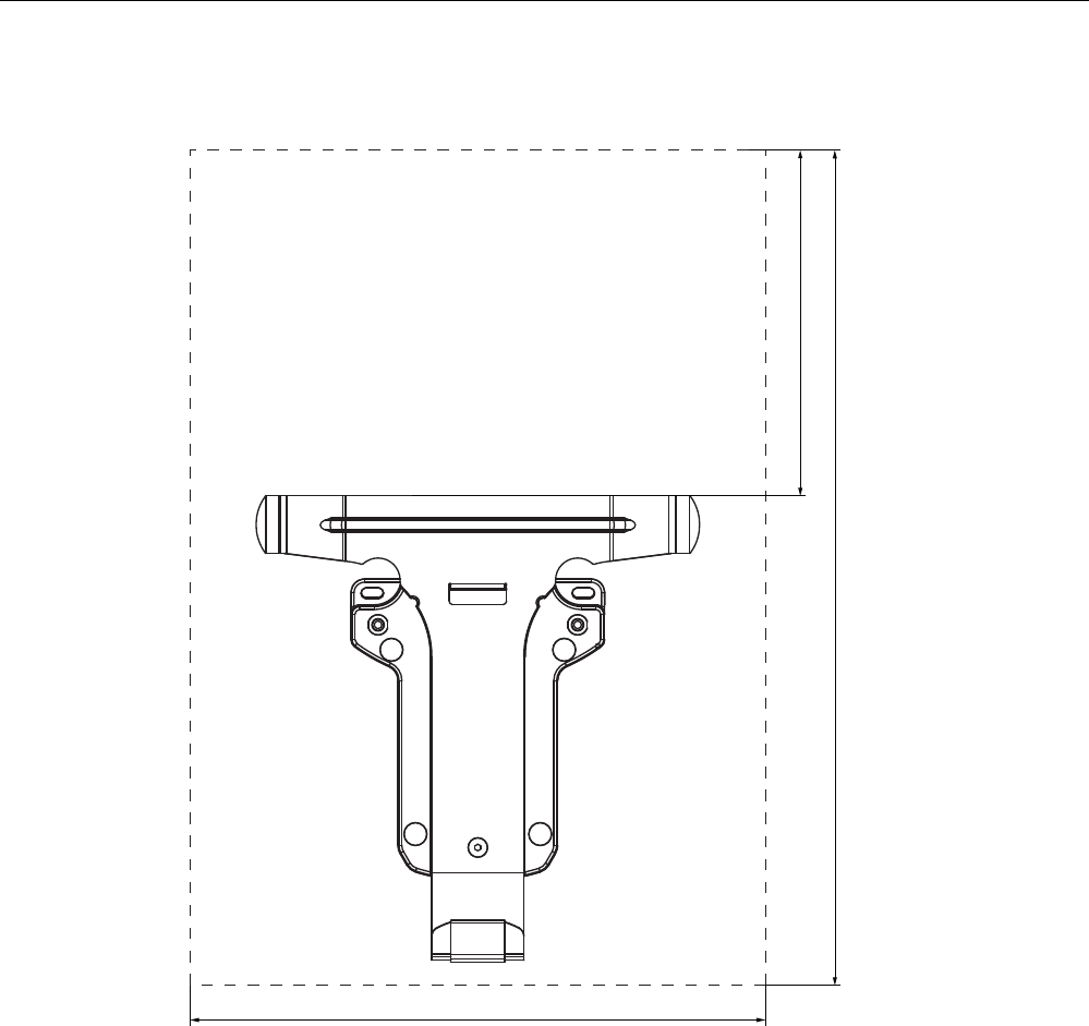
Planning the use
3.8 Planning the installation location of signal lamps
Wireless Teach Pendant F IWLAN V2
Operating Instructions, 08/2010, A5E02453837-01 57
Maintaining clearances
The following clearance is required around the docking station:
$OOGLPHQVLRQVLQPP
3.8 Planning the installation location of signal lamps
You will need a signal lamp for a machine operated in fail-safe mode with the enabling
button. The signal lamp notifies the operator that he/she has logged on to the machine.
Plan a clearly visible installation location for the signal lamp that is assigned to a machine.
PRELIMINARY II
1.7.2010

Planning the use
3.9 Coexistence of the frequency bands
Wireless Teach Pendant F IWLAN V2
58 Operating Instructions, 08/2010, A5E02453837-01
3.9 Coexistence of the frequency bands
Coexistence in the 2.4 band
The use of the HMI device does not affect the communication with other devices or only
negligibly so. This applies to the following communication networks:
● WLAN
When adding a WLAN participant, make sure that you observe the conditions described
in the document "Wireless LAN in a PROFINET IO Environment". The conditions vary
depending on the operating mode and the requirement for PNIO refresh times. See
Guideline for the Use of Industrial Wireless LAN in a PROFINET IO Environment
(http://support.automation.siemens.com/WW/view/en/31938420).
● Standard RFID system according to ISO 15693
● Communication protocols that are used for office networks, smoke detectors, bar code
scanners etc. in the 2.4 GHz range
You need to plan the radio channels when operating such devices simultaneously in the
2.4 GHz band – see "SCALANCE W-700" configuration manual
(http://support.automation.siemens.com/WW/view/en/32816761)". Otherwise sufficient
bandwidth for communications cannot be guaranteed.
● ZigBee devices
Coexistence with other communication networks
Moreover, coexistence is ensured for the following communication networks:
● Coexistence in the 5 band
Planning for the radio channels of all WLAN systems in use is required to ensure
sufficient bandwidth for communication.
● WirelessHART
You need to plan for the radio channels for simultaneous operation of Industrial Wireless
LAN systems and WirelessHART systems in the 2.4 GHz band. Avoid simultaneous use
of overlapping frequency ranges. There is overlapping between Industrial Wireless LAN
and WirelessHART – see "SCALANCE W-700" configuration manual
(http://support.automation.siemens.com/WW/view/en/32816761), section 2.3.
See also
WLAN properties (Page 51)
PRELIMINARY II
1.7.2010

Planning the use
3.10 Planning information security
Wireless Teach Pendant F IWLAN V2
Operating Instructions, 08/2010, A5E02453837-01 59
3.10 Planning information security
Information security is a vital aspect in automation engineering particularly to ensure the
availability and interference-free operation of industrial plants. To ensure communication and
information security via WLAN for the HMI device, you need to protect the communication
system from attack.
Expect:
● Attacks from the outside
To protect against external attacks, you must protect the WLAN in the same way you
would protect office communication, namely with a firewall.
● Attacks from the inside
Investigations have shown that the majority of attacks on information security are
executed from inside the plant. To ensure information security, you need to take action
for:
– Configuration and parameter settings
Possible objectives of an attack are the project and the parameter settings of the HMI
device.
– Productive operation data
The productive data can be manipulated, for example by sending a series of false
PROFIsafe message frames which prevent the plant from being switched off.
Data transfer between HMI device and access point is protected by the AES
encryption mechanism. Manipulation of productive data is prevented in this manner.
Organizational measures
The organizational measures to ensure information security are described in the following
documents:
● IEC 61784-3-3:2007 Functional safety field busses – Additional specifications for CPF 3
● PROFIsafe - Environmental Requirements
Specify the organizational measures you must implement in accordance with your plant's
requirements to achieve the highest possible information security for communication via
WLAN. In doing so, take into consideration:
● Configuration phase
● Process control phase
Check the interplay of the specified measures.
PRELIMINARY II
1.7.2010

Planning the use
3.10 Planning information security
Wireless Teach Pendant F IWLAN V2
60 Operating Instructions, 08/2010, A5E02453837-01
Checklist
Perform the following tasks for application planning and confirm the implementation of each
step in the following checklist. The tasks only conditionally required for PROFIsafe
compliance are marked
italic
in the checklist.
● Access point
Task Additional information Check
Select the installation site and antenna
characteristics of the access point in such a
manner that only the desired area is supplied
with wireless capacity. In this regard note that
wireless waves spread out horizontally as well
as vertically.
Access point operating instructions
"SINEMA E" planning program
(http://www.siemens.com/sinema)
Install the access points at locations secured
against attack, for example, in suspended
ceilings.
This can prevent manipulation at the access
point or at the Ethernet connection to the LAN.
–
Always use cable connections to configure
access points.
–
Change the administrative password set.
"SCALANCE W-700" configuration
manual
(http://support.automation.siemens.
com/WW/view/en/32816761)
Hidden SSID
Configure the access point so that the SSID of
the radio cell remains hidden.
"SCALANCE W-700" configuration
manual
(http://support.automation.siemens.
com/WW/view/en/32816761)
Change the SSID setting. Entering and deleting a password
(Page 114)
PRELIMINARY II
1.7.2010

Planning the use
3.10 Planning information security
Wireless Teach Pendant F IWLAN V2
Operating Instructions, 08/2010, A5E02453837-01 61
● Communication network
Task Additional information Check
Examine the application environment with a
spectrum analyzer and via WLAN measurement
programs for possible radio interference.
If you detect sources of interference, specify the
appropriate remedial measures. Log the results.
–
Only operate the communication network in the
infrastructure mode.
System manual "Basics on Setting
up an Industrial Wireless LAN"
(http://support.automation.siemens.
com/WW/view/en/9975764),
"Network architecture" section
Isolate the automation networks from all other
networks. Use routers and firewalls or VPNs at
points where connections to these networks are
needed. Limit the communication between the
networks to the absolute minimum required.
Operating Instructions "SCALANCE
X-400"
(http://support.automation.siemens.
com/WW/view/en/19625216)
Operating Instructions "SCALANCE
S and SOFTNET Security Client"
(http://support.automation.siemens.
com/WW/view/en/21719299)
Prevent unauthorized participation in the
wireless communication using authentication
mechanisms.
"SCALANCE W-700" configuration
manual
(http://support.automation.siemens.
com/WW/view/en/32816761)
● HMI device
Task Additional information Check
Use a password to protect the Control Panel
and Taskbar of the HMI device against
unauthorized access.
Section "Entering and deleting a
password (Page 114)"
Enable the data channel used to transfer the
project to the HMI device only during the
transfer of the project.
Section "Programming the data
channel (Page 142)"
Enable encryption for data transmission in the
WLAN configuration.
Change the default password for accessing the
WLAN configuration in the Web Based
management.
Section "Configuring the WLAN
connection (Page 116)"
PRELIMINARY II
1.7.2010

Planning the use
3.10 Planning information security
Wireless Teach Pendant F IWLAN V2
62 Operating Instructions, 08/2010, A5E02453837-01
● F-CPU and safety program
Task Additional information Check
Use passwords to protect access to the F CPU
and safety program.
Programming and operation manual
"S7 Distributed Safety - Configuring
and Programming"
(http://support.automation.siemens.
com/WW/view/en/22099875),
section "Protection against attack"
● WinCC flexible ES
Task Additional information Check
Protect WinCC flexible Es with general IT
technologies.
Examples:
Protect the PC where the ES is installed on
the operating system level with a password.
Use a suitable encryption program to
encrypt files, folders, and partitions.
Assign the access right for a drive only to a
specific group of people.
Encrypt the data with mechanisms provided
by MS Windows.
–
Use a password to protect the "Effective range
name" object.
WinCC flexible Information System
You can find addition information on the topic of data security in the following publications:
● System manual "Fundamentals - Industrial Wireless LAN", section "Information security
of wireless communication in accordance with IEEE 802.11".
● Brochure "Wireless Communication Systems and their Security Aspects" published by the
German Federal Agency for Security in Information Technology
PRELIMINARY II
1.7.2010

Wireless Teach Pendant F IWLAN V2
Operating Instructions, 08/2010, A5E02453837-01 63
Mounting and connection 4
4.1 Check the scope of delivery
Check the scope of delivery for completeness and visible signs of transport damage.
NOTICE
Do not use damaged parts
If you use defective parts from the scope of delivery, you may experience malfunctions.
If you find defective parts in the scope of delivery, contact your Siemens partner. Only
install undamaged parts.
4.2 Installing an RFID tag
Requirement
● 1 RFID tag
● 1 fixing pocket
● 2 M4 cylinder head screws with nuts, if required
● An installation location has been selected for the RFID tag as described in the section,
"Planning an installation location for RFID tags (Page 54)".
If installing on a metallic base:
● 1 spacer
● 4 M4 cylinder head screws with nuts, if required
Note
The mounting brackets on both sides of the spacer permit fixation with cable ties.
0RXQWLQJKROH
0RXQWLQJKROH
%UDFNHW
PRELIMINARY II
1.7.2010

Mounting and connection
4.3 Installing the docking station
Wireless Teach Pendant F IWLAN V2
64 Operating Instructions, 08/2010, A5E02453837-01
Procedure- with a metallic installation location
Proceed as follows:
1. Position the spacer on the installation location.
2. Mark the fastening holes with a marking-off tool.
3. Drill two through-holes or two threaded holes, M4.
4. Mount the spacer.
5. Bend the tabs on the fixing pocket to the rear at right angles.
6. Slide the RFID tag into the fixing pocket.
7. Slide the tabs of the fixing pocket into the spacer.
The tabs snap into place and are secured by studs.
Procedure – with a non-metallic installation location
Proceed as follows:
1. Position the fixing pocket on the installation location.
2. Mark the fastening holes with a marking-off tool.
3. Drill two through-holes or two threaded holes, M4.
4. Fasten the fixing pocket.
5. Slide the RFID tag into the fixing pocket.
4.3 Installing the docking station
Requirement
● 2 M5 cylinder head screws with nuts, if required
Read the section "Planning the installation location and clearance of the docking station
(Page 56)".
Procedure
Proceed as follows:
1. Place the docking station on the mounting surface.
2. Mark the fastening holes with a marking-off tool.
3. Drill two through holes or two threaded holes M5.
4. Mount the docking station.
PRELIMINARY II
1.7.2010

Mounting and connection
4.4 Connecting the docking station and charger
Wireless Teach Pendant F IWLAN V2
Operating Instructions, 08/2010, A5E02453837-01 65
4.4 Connecting the docking station and charger
The power supply provides electricity to the docking station and charger.
NOTICE
Use only approved power supplies
If you use an unapproved power supply, damage may occur to the HMI device.
Only use the power supply approved for the HMI device.
Danger of overheating
There is danger of overheating if you cover the power supply and thereby inhibit the air
circulation.
Do not cover the power supply unit.
Note
Unplug the mains connector of the power supply to ensure complete electrical isolation.
The power supply is designed for operation on grounded power supply networks (TN
systems to VDE 0100, Part 300, or IEC 364-3).
Operation is not authorized on ungrounded or impedance-grounded power networks (IT
systems).
Read the section "ESD guideline (Page 251)".
Requirement
● The docking station is installed or the charger is ready for operation.
● The power supply is ready.
Procedure – disconnection
Proceed as follows:
1. Store the power supply unit in a safe place.
2. Insert the plug of the 24 V power cable into the socket of the docking station or charger.
3. Connect the power supply unit to the mains.
Procedure – disconnection
Proceed as follows:
1. Pull the plug of the 24 V power cable out of the socket of the docking station or out of the
charger.
2. Disconnect the power supply unit from the mains.
See also
Power supply unit (Page 19)
PRELIMINARY II
1.7.2010

Mounting and connection
4.5 Connecting the HMI device
Wireless Teach Pendant F IWLAN V2
66 Operating Instructions, 08/2010, A5E02453837-01
4.5 Connecting the HMI device
4.5.1 Safety instructions
CAUTION
Use only approved devices
Non-approved devices may cause malfunctions.
Only operate the HMI device with approved devices as specified in the section, "Overview
(Page 13)".
Malfunction possible
If the HMI device is switched on and lying on its front, any one of the operator controls can
trigger a malfunction.
Switch off the HMI device whenever possible.
Damage to the HMI device by foreign objects and liquids
Damage may occur to the HMI device if it is opened by unauthorized personnel. Foreign
bodies or liquids must not penetrate the interior of the HMI device or come into contact with
the printed circuit board.
The connection and battery compartments therefore may only be opened by professional
personnel for servicing.
NOTICE
Do not exceed the bridging time
If the main rechargeable battery is removed, the HMI device supplied by the rechargeable
buffer battery. The maximum bridging time is 20 seconds. If you exceed the bridging time,
the HMI device may switch off automatically. This triggers a shutdown or rampdown of an
integrated HMI device.
Do not exceed the bridging time!
Opening the connection or battery compartment
The HMI device does not meet degree of protection IP65 when the connection or battery
compartment is open.
Do not open the connection or battery compartment if dust or moisture can enter the
device. Close an open compartment completely.
See also
ESD guideline (Page 251)
PRELIMINARY II
1.7.2010
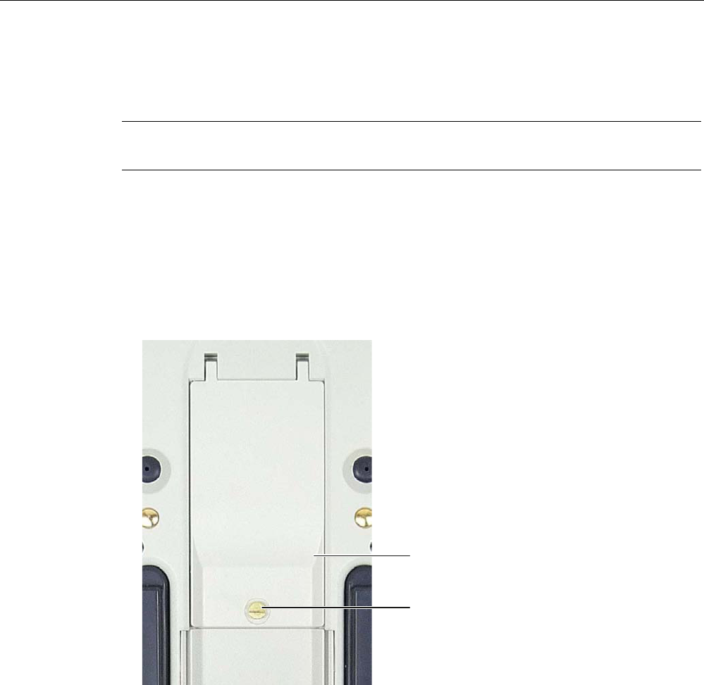
Mounting and connection
4.5 Connecting the HMI device
Wireless Teach Pendant F IWLAN V2
Operating Instructions, 08/2010, A5E02453837-01 67
4.5.2 Opening and closing the terminal compartment
The connection compartment may not be opened while the HMI device is in operation.
Opening the connection compartment does not interrupt the power supply to the HMI device.
Note
Read the section "Safety instructions (Page 66)".
Requirement ● Screwdriver, size 6.5 x 150
Procedure – opening the connection compartment
Proceed as follows:
1. Lay the HMI device on its front side.
2. Loosen the screws.
&RYHUIODS
6FUHZ
3. Lift the cover.
The connection compartment opens.
Procedure – closing the connection compartment
Proceed as follows:
1. Close the cover of the connection compartment.
When closing the connection compartment, ensure that:
– The seal is present and properly positioned.
– The connection cables of the rechargeable buffer battery are not pinched.
2. Tighten the screws.
The connection compartment is open.
PRELIMINARY II
1.7.2010
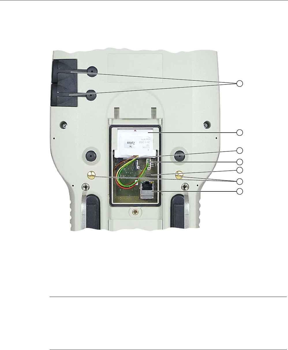
Mounting and connection
4.5 Connecting the HMI device
Wireless Teach Pendant F IWLAN V2
68 Operating Instructions, 08/2010, A5E02453837-01
4.5.3 Ports and reset button
The following figure shows the interfaces and reset button of the HMI device.
① USB port with cover
② Rechargeable buffer battery
③ Memory card slot
④ Plug and socket for the rechargeable buffer battery
⑤ Reset button
⑥ Contact for the power supply
⑦ RJ45 socket for LAN
Note
The RJ45 interface is only suitable for commissioning.
If you want to use the RJ45 port, the connection compartment must be open. The IP65
degree of protection is no longer met for the Wireless Teach Pendant F IWLAN when the
connection compartment is open.
Do not open the connection compartment if dust or water could enter the device.
All unsaved data will be lost when you press the reset button. Press the reset button only
when the HMI device is no longer working properly and no longer responds to input.
PRELIMINARY II
1.7.2010
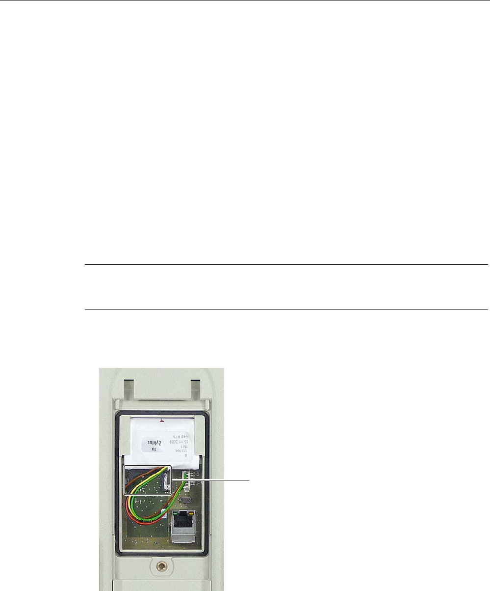
Mounting and connection
4.5 Connecting the HMI device
Wireless Teach Pendant F IWLAN V2
Operating Instructions, 08/2010, A5E02453837-01 69
4.5.4 Inserting a memory card
Only use memory cards approved for use with the HMI device, see section Accessories
(Page 16).
The following can be saved to the memory card of the HMI device:
● Operating system
● Applications
● Data
The memory card can be inserted and removed during operation. Do not remove the
memory card while data is being accessed, for example during data backup or recipe
transfer.
Requirement ● The connection compartment opens.
Procedure – inserting a memory card
Note
Read sections "Safety instructions (Page 66)" and "Opening and closing the terminal
compartment (Page 67)".
Proceed as follows:
1. Open the connection compartment.
2. Insert the memory card into the slot.
6ORW
An arrow on the memory card indicates the front side and the direction of insertion. When
the memory card is correctly inserted into the slot, it stands approx. 3 mm proud of the
slot.
3. Close the connection compartment or proceed with the following tasks.
PRELIMINARY II
1.7.2010

Mounting and connection
4.5 Connecting the HMI device
Wireless Teach Pendant F IWLAN V2
70 Operating Instructions, 08/2010, A5E02453837-01
Procedure – using a memory card for the first time
Note
The first time you use a memory card, the HMI device will prompt you to format it. All data is
lost on the memory card during formatting.
Back up existing data, if necessary, before you use the memory card in the HMI device.
Proceed as follows:
1. Cancel the formatting procedure by pressing "ESC".
2. Remove the memory card from the slot.
3. Back up data that are still needed.
4. Insert the memory card into the slot.
5. Format the memory card.
Procedure – removing a memory card
Proceed as follows:
1. Pull the memory card out of the slot.
2. Store the memory card in a safe place.
3. Close the connection compartment.
PRELIMINARY II
1.7.2010
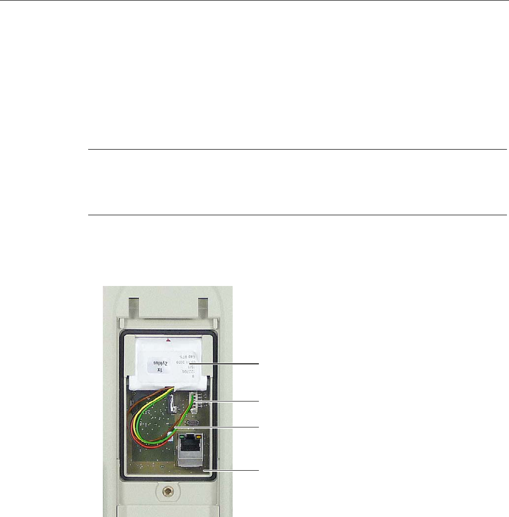
Mounting and connection
4.5 Connecting the HMI device
Wireless Teach Pendant F IWLAN V2
Operating Instructions, 08/2010, A5E02453837-01 71
4.5.5 Connecting the rechargeable buffer battery
Before you begin operation of the HMI device, you need to connect the rechargeable buffer
battery.
You can only replace the main rechargeable battery without switching off the HMI device
when the rechargeable buffer battery is connected.
Procedure
Note
Read the following sections:
"Opening and closing the terminal compartment (Page 67)"
"Safety instructions (Page 72)".
Proceed as follows:
1. Open the connection compartment.
2. Plug the connector if the cable into the socket on the printed circuit board.
5HFKDUJHDEOHEXIIHUEDWWHU\
&RQQHFWLQJFDEOH
3OXJDQGVRFNHW
3ULQWHGFLUFXLWERDUG
3. Position the cable so that it is not pinched when you close the connection compartment.
4. Close the connection compartment.
PRELIMINARY II
1.7.2010

Mounting and connection
4.5 Connecting the HMI device
Wireless Teach Pendant F IWLAN V2
72 Operating Instructions, 08/2010, A5E02453837-01
4.5.6 Replacing and charging the main rechargeable battery
4.5.6.1 Safety instructions
CAUTION
Charging and discharging the rechargeable battery
There is a risk of fire and, in extreme cases, explosion in the following situations!
Incorrect charging and discharging of the rechargeable battery
Reverse polarity
Short-circuit
Only charge the rechargeable battery in the HMI device or in a charger approved for the
HMI device.
Contact with battery fluid
If used incorrectly, fluid can leak from the battery.
Avoid contact with the battery fluid. If battery fluid comes in contact with skin, rinse it off
with water. If battery fluid comes into contact with the eyes, seek medical advice.
NOTICE
Use only approved batteries
If you use non-approved batteries, malfunctions may occur as a result.
Only use batteries that are approved for the HMI device.
Fully charge the main rechargeable battery before first use
If you attempt to use a main rechargeable battery in the HMI device in its factory state, the
HMI device will not start.
Fully charge the main rechargeable battery before inserting it in the HMI device.
Note
The following applies to lithium-ion rechargeable batteries:
Do not crush
Do not heat or burn
Do not short-circuit
Do not disassemble
Do not immerse in liquids – the rechargeable battery may rupture or burst
Store unused rechargeable batteries away from the following items which can cause the
contacts to be bridged.
These include:
– Paper clips
– Coins
– Keys
– Nails
– Screws or other small metal objects
PRELIMINARY II
1.7.2010

Mounting and connection
4.5 Connecting the HMI device
Wireless Teach Pendant F IWLAN V2
Operating Instructions, 08/2010, A5E02453837-01 73
4.5.6.2 Replacing the main rechargeable battery
You can replace the main rechargeable battery during operation. The rechargeable buffer
battery supplies the power while the main rechargeable battery is being replaced. The
maximum bridging time is 20 seconds. If you exceed the buffer time, the HMI device will
switch off.
During the bridging time, the following features are disabled:
● Display backlighting
● All LEDs except for "SAFE" and "RNG"
● The illuminated pushbuttons
● The USB ports
Note
Read the section "Safety instructions (Page 72)".
If the capacity of a rechargeable battery drops to 50 percent of the original capacity, use
a new rechargeable battery. A new rechargeable battery is needed after 500 full charge
cycles.
Example of a full charge cycle:
The charge level of a rechargeable battery decreases from 100 percent to 80 percent.
The rechargeable battery is charged again in this state and then reaches 100 percent.
Discharging to 80 percent and recharging to 100% adds up to a full charge cycle.
Keep main rechargeable batteries in stock.
PRELIMINARY II
1.7.2010
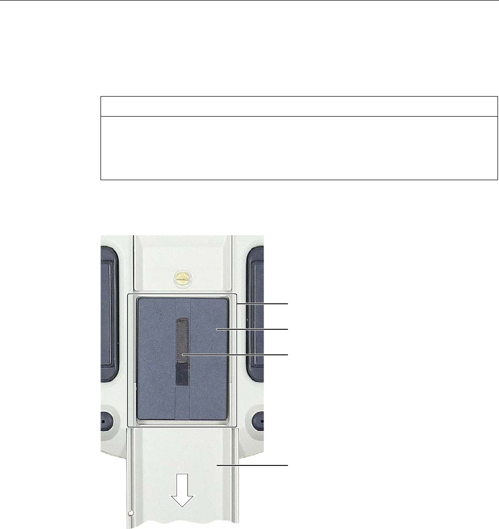
Mounting and connection
4.5 Connecting the HMI device
Wireless Teach Pendant F IWLAN V2
74 Operating Instructions, 08/2010, A5E02453837-01
Procedure
Proceed as follows:
1. Lay the HMI device on its front side.
CAUTION
Potential malfunction when HMI device switched on
If the HMI device is switched on and lying on its front, any one of the operator controls
can trigger a malfunction.
Make sure that no operator control can be triggered when the HMI device is laid down.
2. Slide the compartment cover in the direction of the arrow until it catches.
If you are using the HMI device for the first time, there is no main rechargeable battery in
the battery compartment.
%DWWHU\FRPSDUWPHQW
0DLQUHFKDUJHDEOHEDWWHU\
5LEERQ
&RPSDUWPHQWFRYHU
3. Remove the main rechargeable battery by pulling on the ribbon.
4. Insert a charged main rechargeable battery.
5. Close the compartment cover fully.
PRELIMINARY II
1.7.2010

Mounting and connection
4.5 Connecting the HMI device
Wireless Teach Pendant F IWLAN V2
Operating Instructions, 08/2010, A5E02453837-01 75
4.5.6.3 Charging the main rechargeable battery
The main rechargeable battery is not fully charged when delivered. The main rechargeable
battery is charged:
● In the HMI device while it is sitting in the docking station.
● In the charger
Note
Read the section "Safety instructions (Page 72)".
Before charging the main rechargeable battery, read the documentation that accompanies
the charger.
Requirement
The following devices are available:
● Charger° (Page 18)
● Power supply unit (Page 19)
Procedure – Connecting a charger and charging the main rechargeable battery
Note
When charging a rechargeable battery, the ambient temperature or battery temperature
should not exceed 40° C. The higher the temperature, the longer it will take for the
rechargeable battery to fully charge.
Select a location for the charger with a cool ambient temperature. Let the rechargeable
battery cool before charging it. Keep to the permitted ambient conditions.
The main rechargeable battery can be place in the charger before or after connecting the
power supply unit.
Proceed as follows:
1. Store the power supply unit in a safe place.
2. Insert the plug of the power cable into the socket of the charger.
3. Connect the charger to the mains.
The "POWER" LED lights up.
4. Place the rechargeable battery into the charger.
The rechargeable battery is fully charged once all five LEDs are lit. See section "Showing
the battery charge (Page 76)".
PRELIMINARY II
1.7.2010
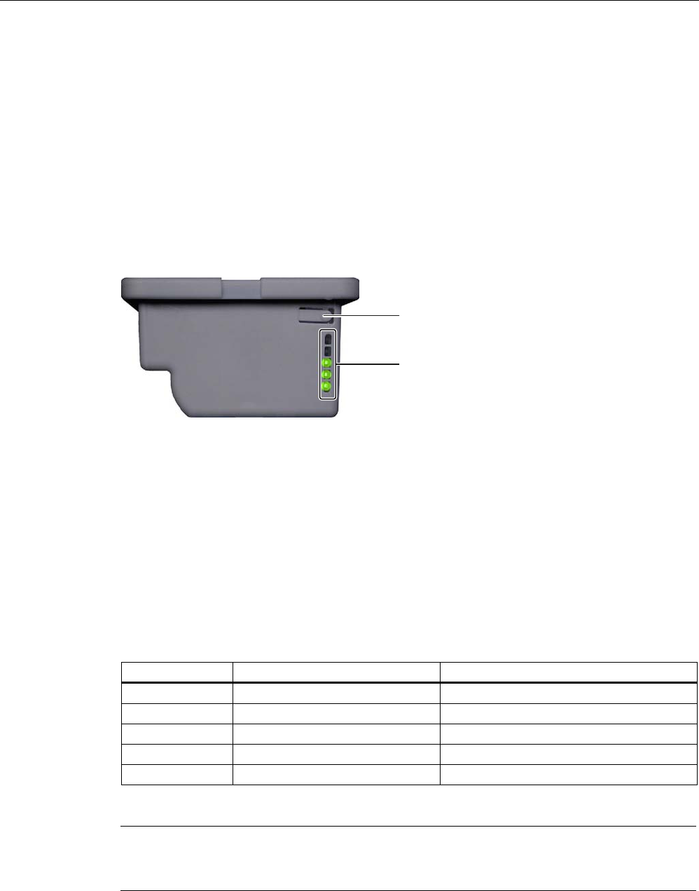
Mounting and connection
4.5 Connecting the HMI device
Wireless Teach Pendant F IWLAN V2
76 Operating Instructions, 08/2010, A5E02453837-01
Procedure – Disconnecting the charger
Proceed as follows:
1. Pull the plug of the power cable out of the charger's socket.
The "POWER" LED goes out.
2. Disconnect the power supply from the mains.
4.5.6.4 Showing the battery charge
The main rechargeable battery features an LED array. The respective LEDs indicate the
battery charge.
.H\
/('DUUD\
FRQVLVWLQJRIILYH/('V
Requirement
● The main rechargeable battery is removed from the HMI device.
Procedure
Proceed as follows:
1. Press the button.
The LED lights when the button is released after approx. 5 seconds.
The number of illuminated LEDs indicates the charge status.
Number of LEDs Flashes for Lights for
1 0 to 19 % of the charge capacity 20 to 39 % of the charge capacity
2 - 40 to 59 % of the charge capacity
3 - 60 to 79 % of the charge capacity
4 - 80 to 96 % of the charge capacity
5 - 97 to 100 % of the charge capacity
If all the LEDs light up, the main rechargeable battery is fully charged.
Note
This applies to rechargeable batteries that are stored – read the section "Maintenance and
care (Page 237)".
PRELIMINARY II
1.7.2010
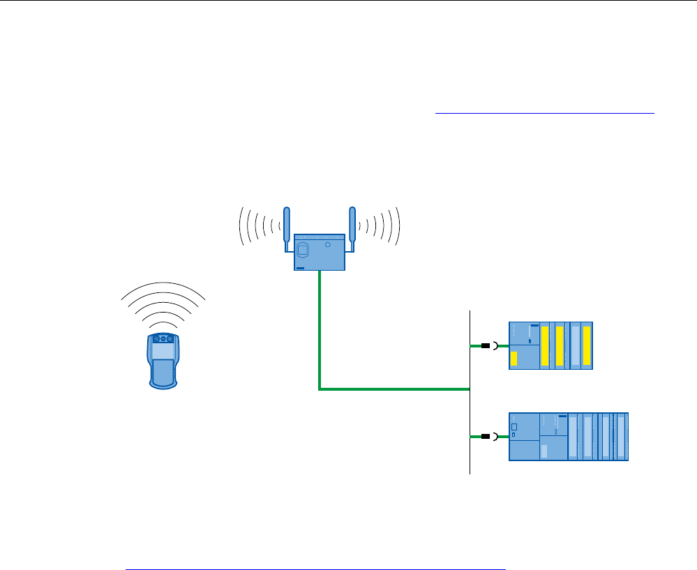
Mounting and connection
4.5 Connecting the HMI device
Wireless Teach Pendant F IWLAN V2
Operating Instructions, 08/2010, A5E02453837-01 77
4.5.7 Connecting the PLC
Only use approved components to connect a SIMATIC S7 PLC. You can find more
information on this on the Internet in Industry Mall (http://mall.automation.siemens.com).
Configuration graphic
The following figure shows the connection between the PLC and the HMI device.
(WKHUQHW
6,0$7,&6)
6,0$7,&6
See also
System manual "Basics on Setting up an Industrial Wireless LAN"
(http://support.automation.siemens.com/WW/view/en/9975764)
PRELIMINARY II
1.7.2010
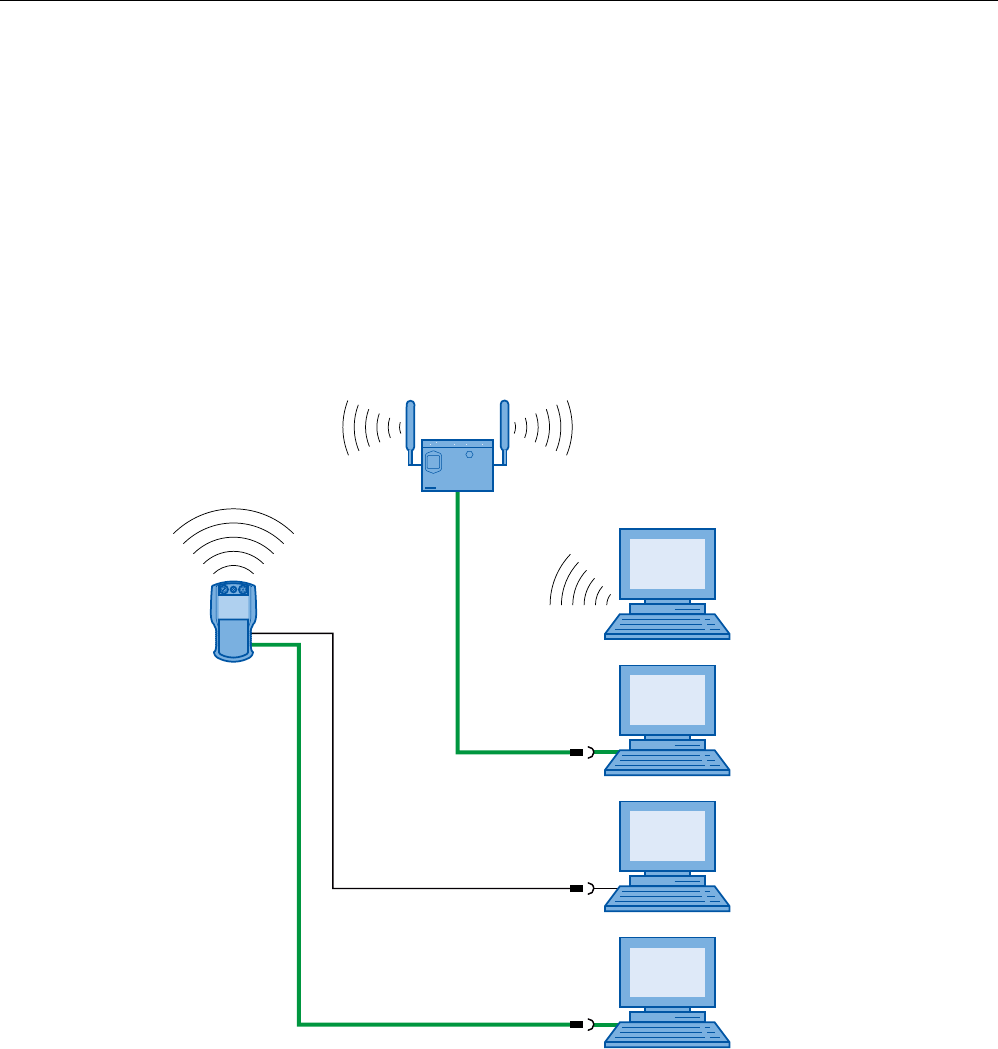
Mounting and connection
4.5 Connecting the HMI device
Wireless Teach Pendant F IWLAN V2
78 Operating Instructions, 08/2010, A5E02453837-01
4.5.8 Connecting the configuration PC
You have the following options for connecting a configuration PC to the HMI device:
● Connection via WLAN
● Connection via LAN and RJ45 interface
● Connection via USB
Configuration graphic
The following figure illustrates the options for connection between the HMI device and the
configuration PC.
(WKHUQHW
(WKHUQHW
86%
PRELIMINARY II
1.7.2010

Mounting and connection
4.5 Connecting the HMI device
Wireless Teach Pendant F IWLAN V2
Operating Instructions, 08/2010, A5E02453837-01 79
NOTICE
Adhere to the USB connection sequence
You will not be able to transfer a project to the HMI device if you do not adhere to the
connection sequence.
Observe the following sequence when connecting by USB:
1. HMI device
2. PC
USB host-to-host cable
You will not be able to transfer a project to the HMI device if you use the driver for the USB
host-to-host cable.
Use only the driver for the USB host-to-host cable that is included in the WinCC flexible
package.
Note
Point-to-point connection
Use a cross cable for a point-to-point connection. The HMI device and the PC can also be
subscribers in a local area network.
Connection via WLAN
In its factory state, the WLAN interface of the HMI device is disabled. Before you access the
HMI device from the configuration PC via WiFi, you need to appropriately configure the
access point and HMI device in infrastructure mode. An ad hoc wireless network is not
possible.
Restoring the factory settings
To update the operating system and reset the factory settings, you need to connect the HMI
device to the configuration PC via the RJ45 port. Connect a configuration PC directly to the
HMI device only as long as it is necessary. You can find additional information in the
"Restoring factory settings (Page 194)" section.
PRELIMINARY II
1.7.2010

Mounting and connection
4.5 Connecting the HMI device
Wireless Teach Pendant F IWLAN V2
80 Operating Instructions, 08/2010, A5E02453837-01
4.5.9 Connecting a USB device
You can connect the following devices to the USB port of the HMI device:
● External mouse
● External keyboard
● USB memory stick
Only connect industrial devices.
Note when connecting
NOTICE
USB interface only suitable for commissioning
Use the USB interface for commissioning and maintenance only.
The cable length of the connected USB devices may not exceed 3 meters.
IP65 protection with a USB device not guaranteed
If a USB device is connected to one of the USB ports, the HMI device does not comply with
the IP65 degree of protection.
Do not connect a USB device if dust or moisture can enter the device.
Devices with a separate power supply
Self-powered devices cause a malfunctions in the HMI device. A PC or configuration PC is
an exception.
Only connect a configuration PC or PC to the USB port.
Malfunction
A USB device that places too much power consumption load on the USB port can damage
the HMI device.
Be aware of the maximum power load placed on the USB port.
Access to USB port
The USB port is disabled while the main rechargeable battery is being replaced. You
cannot save data to a USB memory stick, for example, while the main rechargeable battery
is being replaced.
Ensure no one tries to access the USB port while the main rechargeable battery is being
replaced.
Note
Devices without a separate power supply connected to the USB port increase the power
load. This will reduce the service life of the HMI device.
See also
Specifications (Page 244)
PRELIMINARY II
1.7.2010
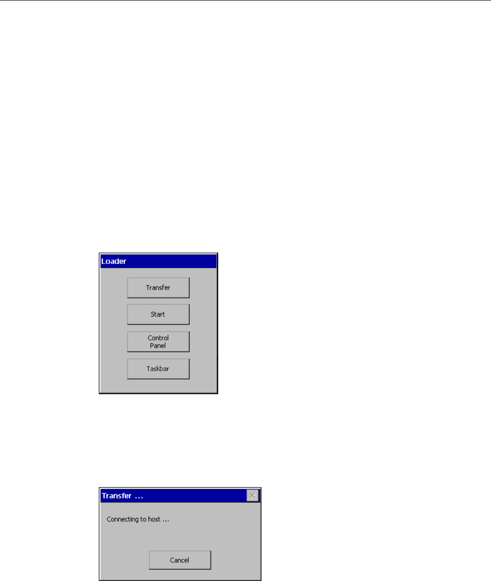
Mounting and connection
4.6 Switching on and testing the HMI device
Wireless Teach Pendant F IWLAN V2
Operating Instructions, 08/2010, A5E02453837-01 81
4.6 Switching on and testing the HMI device
When the HMI device is initially put into operation, there is no project. Ethernet is set as the
data transfer channel.
Requirement
● A charged main rechargeable battery is inserted in the HMI device.
Procedure
Proceed as follows:
1. Briefly press the "ON/OFF" button.
The "PWR" LED lights up – see section "LED display (Page 85)". The display then lights.
A progress bar is displayed during startup.
The loader is displayed once the operating system has started.
If a charged main rechargeable battery is inserted, the "BAT" LED lights up. The HMI
device automatically switches to "Transfer" mode if the following two requirements are
met:
– No project is loaded on the device.
– At least one data channel has been configured.
The following dialog appears:
2. Press the "Cancel" button.
The transfer is canceled. The Loader appears.
PRELIMINARY II
1.7.2010

Mounting and connection
4.7 Switching off the HMI device
Wireless Teach Pendant F IWLAN V2
82 Operating Instructions, 08/2010, A5E02453837-01
Result
The HMI device is ready for operation when the loader displays one of the following dialogs:
● "Transfer" dialog
● "Testing enabling button" dialog
4.7 Switching off the HMI device
The following procedure applies to an HMI device on which there is no project. The way the
device is switched off therefore differs from that of an integrated HMI device.
Procedure
Proceed as follows:
1. Press the "ON/OFF" button on the HMI device at least 4 seconds.
The HMI device switches off.
See also
Switch-off behavior (Page 208)
PRELIMINARY II
1.7.2010
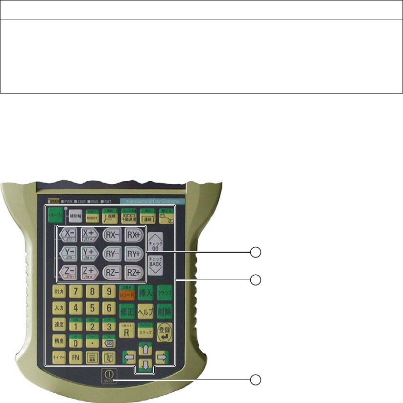
Wireless Teach Pendant F IWLAN V2
Operating Instructions, 08/2010, A5E02453837-01 83
Operator controls and displays 5
5.1 Overview
The standard input unit on the HMI device is the touch screen. All operator controls required
for operation appear in one or more HMI screens on the display after the project starts.
NOTICE
Damage to the touch screen
Never touch the touch screen with a pointed or sharp object. Avoid applying sudden
pressure to the touch screen with a hard object. Both these will substantially reduce the
service life of the touch screen and can even lead to total failure.
Always operate the touch screen of the HMI device with your fingers or with a touch pen.
Membrane keyboard
The following figure shows the membrane keyboard of the
Wireless Teach Pendant F IWLAN.
① Membrane keyboard – six buttons simultaneously enabled
② Membrane keyboard for robot control
③ Key "ON/OFF"
PRELIMINARY II
1.7.2010

Operator controls and displays
5.1 Overview
Wireless Teach Pendant F IWLAN V2
84 Operating Instructions, 08/2010, A5E02453837-01
NOTICE
Damage to the membrane keyboard
Do not touch the keys with a pointed or sharp object. Avoid applying sudden pressure to
the keys with a hard object. Both of these will substantially reduce the service life of the
membrane keyboard and can even lead to total failure.
Only use your fingers to operate the HMI device buttons.
The functions assigned to the keys of the membrane keyboard are defined during
configuration. Outside of the project, the keys of the membrane keyboard have no function.
Displays and other operator controls
● LED display
● EMERGENCY STOP button
● Enabling button
● Rotary switch
● Illuminated pushbutton
PRELIMINARY II
1.7.2010

Operator controls and displays
5.2 LED display
Wireless Teach Pendant F IWLAN V2
Operating Instructions, 08/2010, A5E02453837-01 85
5.2 LED display
An LED display consisting of five LEDs is located on the front of the HMI device. The LED
display shows the operating states for the HMI device and the communication.
/('GLVSOD\
/('IRUURERWDSSOLFDWLRQ
Meaning of LEDs
The LED display is activated when the HMI device is switched on.
LED Color Function LED signals
SAFE Yellow PROFIsafe
communication
The "SAFE" LED lights up when the HMI device is integrated
in the safety program of the F CPU. Requirement – PROFIsafe
communication has been established.
If the "SAFE" LED lights up, the EMERGENCY STOP button is
enabled.
PWR Green Power The "PWR" LED only lights up or flashes when the HMI device
is switched on.
The "PWR" LED lights up under the following circumstances:
The main rechargeable battery is inserted and charged.
The HMI device is in the docking station.
The "PWR" LED flashes when the HMI device is in the
"POWER SAVE 2" operating mode.
COM Green Communication The "COM" LED is off if no WLAN is available.
The "COM" LED flashes when the HMI device attempts to
establish a connection to the WLAN.
The "COM" LED lights when there is a connection between the
HMI device and WLAN.
RNG Green Effective range The "RNG" LED lights when the HMI device is logged on to a
machine.
If a communication error occurs after the HMI device has
logged on to a machine, the "RNG" lights up until PROFIsafe
communication is reestablished and the communication error
has been acknowledged.
The "RNG" LED is off when the HMI device is logged off a
machine.
Refer to the plant documentation for additional information on the meaning of the LEDs.
PRELIMINARY II
1.7.2010
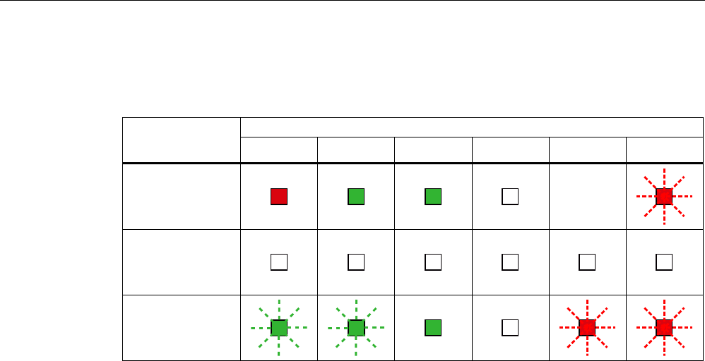
Operator controls and displays
5.2 LED display
Wireless Teach Pendant F IWLAN V2
86 Operating Instructions, 08/2010, A5E02453837-01
Meaning of the "BAT" LED
The "BAT" LED signals the following states depending on the type of power supply:
BAT LED Power supply
① ② ③ ④ ⑤ ⑥
Rechargeable
battery operation,
HMI device on
–
Rechargeable
battery operation,
HMI device off
Docking station,
HMI device on or
off
① Charge at ≤6% capacity
② Charge at > 6% capacity
③ Maximum charge
④ Rechargeable battery not in the HMI device
⑤ Rechargeable battery temperature too high
⑥ Possible error:
Short circuit, discharge current > 8.0 A
Overload, discharge current > 4.0 A
Overload, charge current > 2.8 A
Charging error, cell voltage > 4.3 V
Charging error, cell voltage < 3.0 V
Note the following:
● An error event always has priority.
If an error occurs, the "BAT" LED signals according to column ⑥.
● If the battery is not fully charged, the "BAT" LED signals according to column ⑤.
● If the main rechargeable battery is fully charged, the "BAT" LED signals according to
column ③.
PRELIMINARY II
1.7.2010

Operator controls and displays
5.3 Power management
Wireless Teach Pendant F IWLAN V2
Operating Instructions, 08/2010, A5E02453837-01 87
5.3 Power management
The HMI device is equipped with a power management function. If you do not operate the
HMI device within a configured time period, power management will switch the HMI device to
power saving mode. This extends the operating period of the HMI device until the next time
the main rechargeable battery is replaced or the next time it is charged.
Operating modes in power management
Power management has two operating modes:
● "Power Save 1"
– Reduces the brightness of the touch screen.
– The EMERGENCY STOP button remains available.
– As long as the HMI device is logged on, the enabling button remains enabled.
Note
When you place the HMI device in the docking station, it will automatically assume the
operating state "Power Save 1" after 2 minutes.
If a time period of less than 2 minutes has been specified for activation of
"Power Save 1" mode in the WinCC flexible project, then this time period will be
applied.
● "Power Save 2"
– The touch screen is switched off.
– Other power save measures are activated.
The online help for WinCC flexible describes how to configure power management.
– The EMERGENCY STOP button remains available.
– The rotary switch remains available.
● "Power Save 1" corresponds to the "Reduce brightness" setting.
● "Power Save 2" corresponds to the "Switch off screen" setting.
Note
When the HMI device is logged on to a machine, "Power Save 2" operating mode is not
available.
PRELIMINARY II
1.7.2010
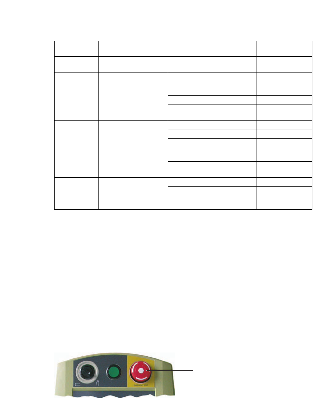
Operator controls and displays
5.4 Safety-related operator controls
Wireless Teach Pendant F IWLAN V2
88 Operating Instructions, 08/2010, A5E02453837-01
Power management for the HMI device provides the following operating modes:
Operating
mode
LED Action Follow-up operating
mode
OFF "PWR" is off.
"BAT" is off.
Briefly press Taste "ON/OFF" ON
Automatically, if no actions are
performed within a configured
time period.
"Power Save 1"
Briefly press Taste "ON/OFF" "Power Save 2"
ON "PWR" lights up.
Press Taste "ON/OFF" for at
least 4 seconds.
OFF
Operation on the touch screen ON
Briefly press Taste "ON/OFF" "Power Save 2"
Automatically, after a configured
time interval if no operations are
carried out
"Power Save 2"
"Power Save 1" "PWR" lights up.
The brightness of the
touch screen is reduced.
Press Taste "ON/OFF" for at
least 4 seconds.
OFF
Briefly press Taste "ON/OFF" ON "Power Save 2" "PWR" flashes.
The touch screen is
switched off. Briefly press Taste "ON/OFF"
and then press it for at least
4 seconds.
OFF
See also
Setting the screen saver (Page 127)
5.4 Safety-related operator controls
5.4.1 EMERGENCY STOP button
The EMERGENCY STOP button is designed with 2-channels and enables an EMERGENCY
STOP of the plant unit with which safety-related communication is taking place. The
EMERGENCY STOP button satisfies the requirements specified in DIN IEC 60947-5-5,1997
Annex K. You can find additional information in the section "Safety functions of the
EMERGENCY STOP button (Page 41)".
(PHUJHQF\VWRSEXWWRQ
Due to its position, the EMERGENCY STOP button is equally accessible for both left-handed
and right-handed persons.
PRELIMINARY II
1.7.2010
Operator controls and displays
5.4 Safety-related operator controls
Wireless Teach Pendant F IWLAN V2
Operating Instructions, 08/2010, A5E02453837-01 89
Storing a non-integrated HMI device
WARNING
EMERGENCY STOP button out of service when HMI device is removed
If the HMI device is not integrated in the safety program of the F-CPU, the EMERGENCY
STOP button will be out of service.
To avoid confusion between HMI devices with enabled and disabled EMERGENCY STOP
buttons during an emergency, only one integrated HMI device should be freely accessible.
If an HMI device is not integrated and not in use, store the HMI device in a location with
protected access.
Requirement
● The EMERGENCY STOP button is evaluated under the condition that the HMI device is
integrated in the safety program of the F-CPU. See section "Safety-related configuration
(Page 161)".
Procedure – Operating the EMERGENCY STOP button
WARNING
Function the EMERGENCY STOP button
The EMERGENCY STOP button has no effect if the HMI device is without power or
removed from the safety program.
Operate the HMI device in mobile mode using the main rechargeable battery or in
stationary mode in the docking station and integrate it in safe-related communication.
NOTICE
Unintentional triggering of the EMERGENCY STOP button
The EMERGENCY STOP button can be triggered unintentionally, thereby bring the plant to
a standstill in the following cases:
When the HMI device is dropped.
When the HMI device is laid on its front.
Handle the HMI device with care!
Proceed as follows:
1. Press the EMERGENCY STOP button fully if a dangerous situation develops.
The EMERGENCY STOP button engages in the EMERGENCY STOP position. The
associated plant unit is stopped.
PRELIMINARY II
1.7.2010
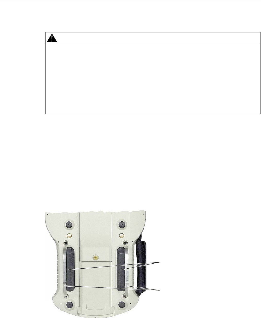
Operator controls and displays
5.4 Safety-related operator controls
Wireless Teach Pendant F IWLAN V2
90 Operating Instructions, 08/2010, A5E02453837-01
Procedure – Releasing the EMERGENCY STOP button
WARNING
EMERGENCY STOP button released
If you have pressed the EMERGENCY STOP button and thereby brought the plant unit to a
standstill, you should only release the EMERGENCY STOP button under the following
conditions:
The reasons for the EMERGENCY STOP have been eliminated.
A safe restart is possible.
The restart should not be performed by releasing the EMERGENCY STOP button.
The project should force the operator to perform an action for restarting independent of
the EMERGENCY STOP button. The safety program must specify that no automatic
restart of the plant is possible simply by releasing the EMERGENCY STOP button.
Proceed as follows:
1. Turn the EMERGENCY STOP button clockwise to its original position.
The EMERGENCY STOP button is released.
5.4.2 Enabling button
The enabling mechanism consists of two enabling buttons which are installed on both sides
of the HMI device. You can find additional information in the "Safety functions of the enabling
mechanism (Page 42)" section.
The enabling button is required to confirm axis movements, for example.
(QDEOLQJEXWWRQ
6DIHW\EDUV
PRELIMINARY II
1.7.2010
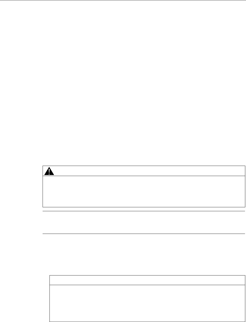
Operator controls and displays
5.4 Safety-related operator controls
Wireless Teach Pendant F IWLAN V2
Operating Instructions, 08/2010, A5E02453837-01 91
The enabling button has three switch settings:
● Neutral position
The enabling button is not pressed.
● Enable
The enabling button is pressed to a middle switch position. The switch position has a
noticeable pressure point. This switch position is used to confirm an entry, for example.
● Panic
The "Panic" switch position is reached as soon as one of the two enabling buttons is fully
pressed. To do this, the pressure point of the "Enable" switching position must be
overcome. An audible switching noise is then heard.
The switch position of the other enabling button is unimportant in this case. The "Panic"
switch position has the same effect as releasing the enabling button. In both switch
positions, the enable is revoked.
Requirement
● The enabling button is evaluated under the condition that the HMI device is integrated in
the safety program of the F-CPU. See section "Safety-related configuration (Page 161)".
Procedure
WARNING
Press the enabling button only as long as necessary
Enabling is a conscious operator action. It is not permitted to continuously press the
enabling button or to fasten it in place.
Press the enabling button only until the operation you wish to enable is completed.
Note
The enabling button only has an effect when the HMI device is logged on to a machine and
the "RNG" LED on the HMI device is lit.
Proceed as follows:
1. Press at least one of the enabling button to reach the "Enable" position.
The controller receives the same signal, regardless of whether one or both enabling
buttons have been pressed.
NOTICE
Enabling button can tilt
If you do not press the center of the enabling button, the enabling button may tilt. The
switching process is delayed by this. A discrepancy error may occur – see section
"Discrepancy error during enabling (Page 258)".
Press the enabling button in the middle.
PRELIMINARY II
1.7.2010
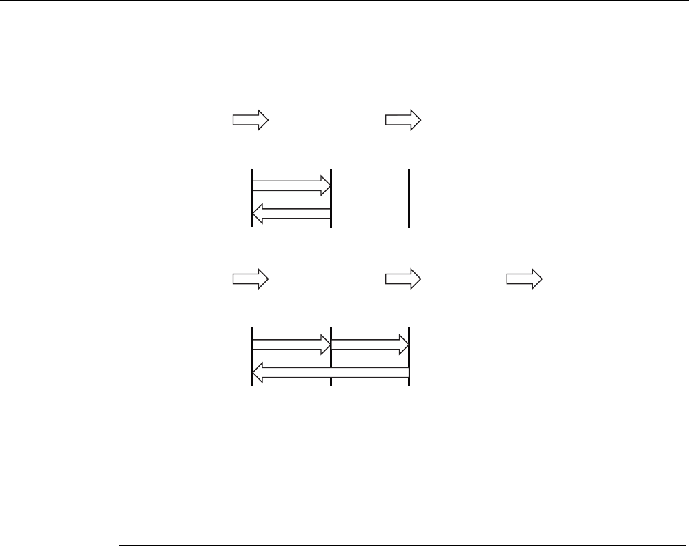
Operator controls and displays
5.4 Safety-related operator controls
Wireless Teach Pendant F IWLAN V2
92 Operating Instructions, 08/2010, A5E02453837-01
Switch settings
The following figure shows the switching sequence for enable.
(%(QDEOLQJEXWWRQ
1HXWUDOSRVLWLRQ
(%OHIW(%ULJKW
(%OHIW(%ULJKW
6ZLWFKVHWWLQJ
(QDEOH
1HXWUDOSRVLWLRQ
[ \
[
\
The following figure shows the switching sequence during panic usage.
(%(QDEOLQJEXWWRQ
1HXWUDOSRVLWLRQ
(%OHIW(%ULJKW
(%OHIW(%ULJKW
6ZLWFKVHWWLQJ
(QDEOH
3DQLF 1HXWUDOSRVLWLRQ
[ X
[
X
\
\
If the operator presses the enabling button in the "Panic" switch position, the "Enable" switch
position will not be evaluated when leaving the panic setting. A new enable can only be
triggered by releasing the enabling button.
Note
The HMI device analyzes the switch settings of the two enabling buttons in the form of an
OR gate.
The enabling button and membrane keyboard can be operated simultaneously.
5.4.3 Testing the function
Perform an annual function test for the enabling button and EMERGENCY STOP button
during commissioning.
Procedure
Proceed as follows:
1. Switch on the HMI device.
2. Press both enabling buttons when the "Test Enabling Button" dialog is shown.
3. Press the EMERGENCY STOP button.
PRELIMINARY II
1.7.2010
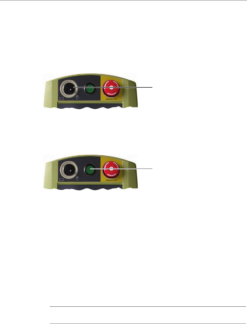
Operator controls and displays
5.5 Operator controls
Wireless Teach Pendant F IWLAN V2
Operating Instructions, 08/2010, A5E02453837-01 93
5.5 Operator controls
5.5.1 Operating the rotary switch
The rotary switch has two positions. The function of the rotary switch is defined in the current
project. Refer to the plant documentation for additional information on the function.
5RWDU\VZLWFK
5.5.2 Operating the illuminated push-button
The function of the illuminated pushbutton is defined in the current project. Refer to the plant
documentation for additional information on the function.
,OOXPLQDWHGSXVKEXWWRQ
5.5.3 Evaluating operator controls
5.5.3.1 Overview
The following information can be obtain between the Wireless Teach Pendant F IWLAN and
PLC:
● Control state of the rotary switch
● Control state of the illuminated pushbutton
● Signal status of the LEDs
There are two ways of transferring information:
● Direct keys
● System functions of WinCC flexible
Note
The following sections are intended for the configuration engineer.
PRELIMINARY II
1.7.2010
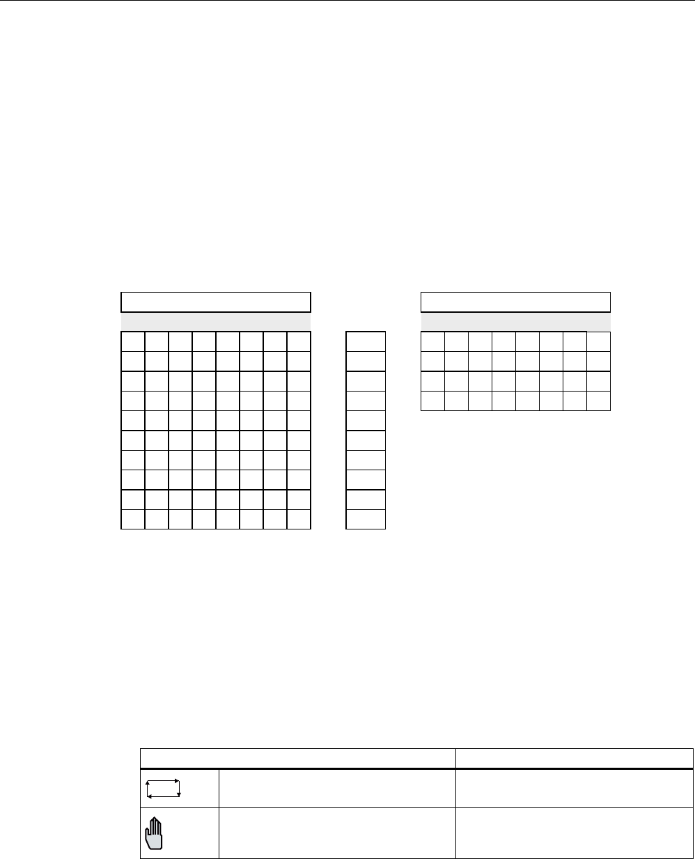
Operator controls and displays
5.5 Operator controls
Wireless Teach Pendant F IWLAN V2
94 Operating Instructions, 08/2010, A5E02453837-01
5.5.3.2 Evaluating operator controls as direct keys
You can configure the operator controls of the HMI device as direct keys. The control states
of the following operator controls are then available directly in the IO area of the controller:
● The control state of the rotary switch
● The control state of the illuminated pushbuttons
● The control state of illuminated pushbutton LED
Byte assignment
The following figure shows the assignment of the keys (inputs) and LEDs (outputs) to the
bytes in the PLC process image.
%XWWRQELWV /('ELWV
%\WH
7
7 6
Q
Q
Q
Q
Q
Q
Q
Q
Q
Q
S Bit for rotary switch
T1 Bit for illuminated pushbutton
The bytes "n+6" to "n+9" contain the direct key bits for the touch buttons.
Refer to your plant documentation for additional information.
Bit assignment
The following tables show the bit assignment for the rotary switch and illuminated
pushbutton:
● Bit coding of rotary switch
State S1
Automatic mode 0
Manual control 1
PRELIMINARY II
1.7.2010

Operator controls and displays
5.6 Holding, operating and setting down the HMI device
Wireless Teach Pendant F IWLAN V2
Operating Instructions, 08/2010, A5E02453837-01 95
● Bit coding of illuminated pushbutton
State T1
Not pressed 0
Pressed 1
● Bit coding of illuminated pushbutton LEDs
State T1
Off 0
On permanently 1
5.6 Holding, operating and setting down the HMI device
Holding and operating the HMI device
The HMI device is equally easy to hold and operate for right-handers and left-handers
because it is designed symmetrically. The free hand can be used to operate the operator
controls on the front side.
Note
Read the section "Safety-related operator controls (Page 88)".
The neck strap provides support for holding of the Wireless Teach Pendant F IWLAN. Use
the velcro closure on the neck strap to attach the strap to HMI device and adjust the length
as necessary.
The method of holding the HMI device shown in the following figure enables you to control
movements in the plant to be monitored during servicing, for example.
The hand holding the HMI device can also be used to activate the enabling button. The
enabling button is optimally accessible. In a dangerous situation, a safety shutdown is
triggered in a panic reaction by releasing or fully pressing the enabling button.
The EMERGENCY STOP button can also be quickly reached with your free hand.
PRELIMINARY II
1.7.2010
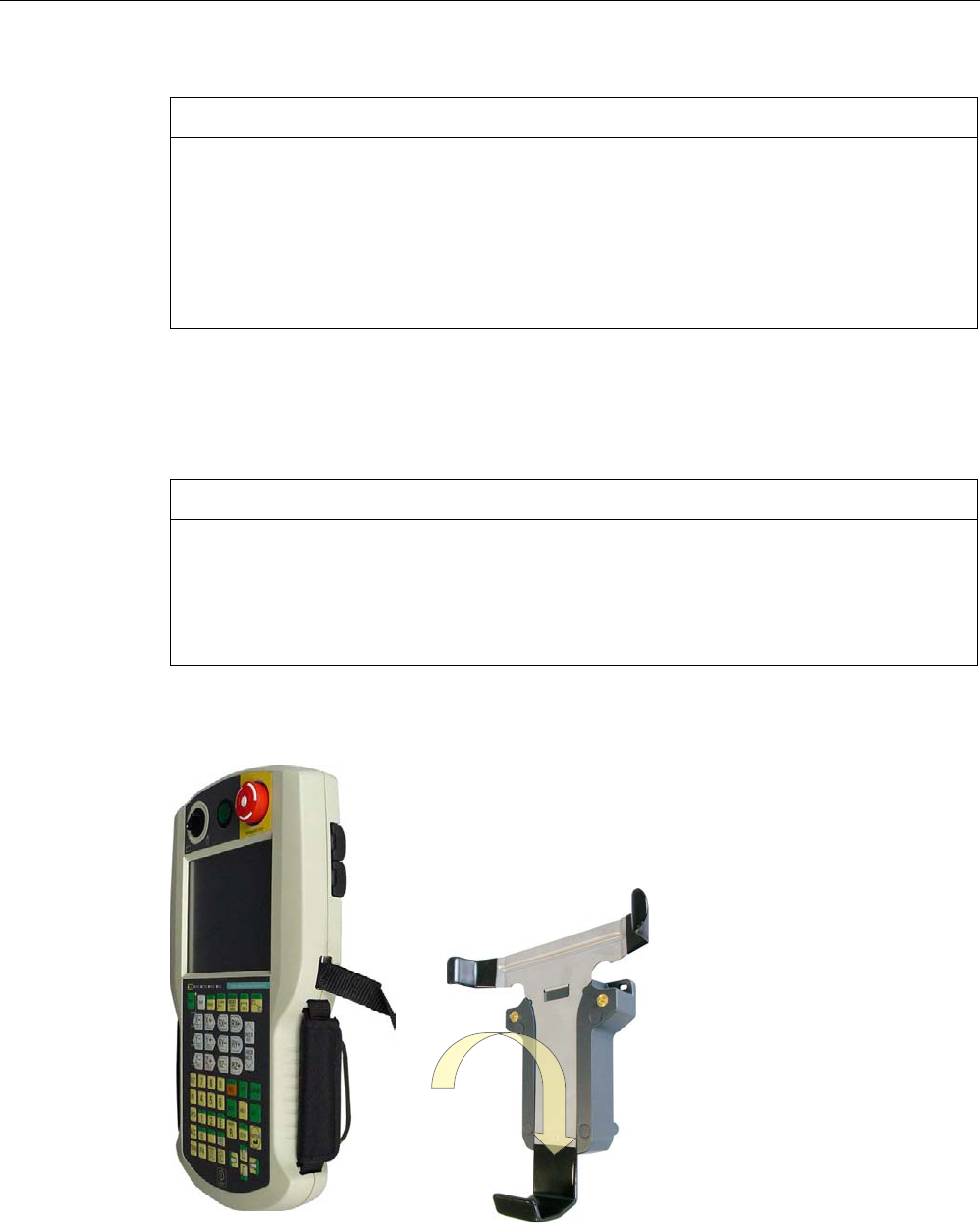
Operator controls and displays
5.6 Holding, operating and setting down the HMI device
Wireless Teach Pendant F IWLAN V2
96 Operating Instructions, 08/2010, A5E02453837-01
NOTICE
Holding the HMI device
If you do not carry the HMI device with the neck strap and hold it as shown, you cannot
operate the EMERGENCY STOP button or enabling button quickly enough in a dangerous
situation.
Carry and hold the HMI device as shown. This especially applies to all hazardous
movements that you control manually. You can then engage the EMERGENCY STOP
button or enabling button as fast as possible in a dangerous situation.
Setting down the HMI device
A docking station is available for safe and stationary storage of the HMI device.
NOTICE
Pressing the EMERGENCY STOP button
If the HMI device is placed in an unsuitable holder, the operability of the EMERGENCY
STOP button will be impaired.
Therefore, only use the docking station especially designed for storing the
Wireless Teach Pendant F IWLAN.
The HMI device can be used as a stationary device when it is placed in the docking station.
The following figure shows how the HMI device is placed in the docking station.
PRELIMINARY II
1.7.2010
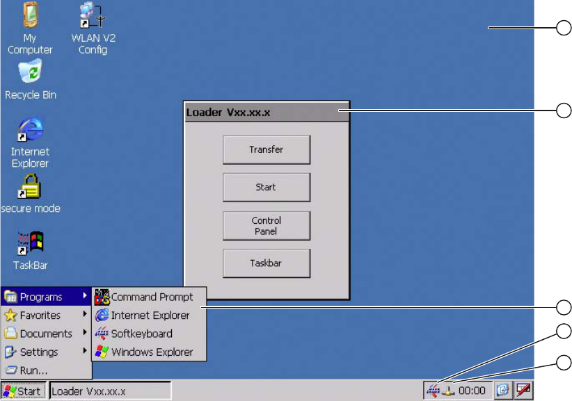
Wireless Teach Pendant F IWLAN V2
Operating Instructions, 08/2010, A5E02453837-01 97
Configuring the HMI device 6
6.1 Desktop and Loader
Once the HMI device is switched on and booted, the display shows the desktop with the
Loader.
① Desktop
② Loader
③ Start menu
④ Icon for screen keyboard
⑤ Icon for displaying IP information about the WLAN/LAN connection
PRELIMINARY II
1.7.2010
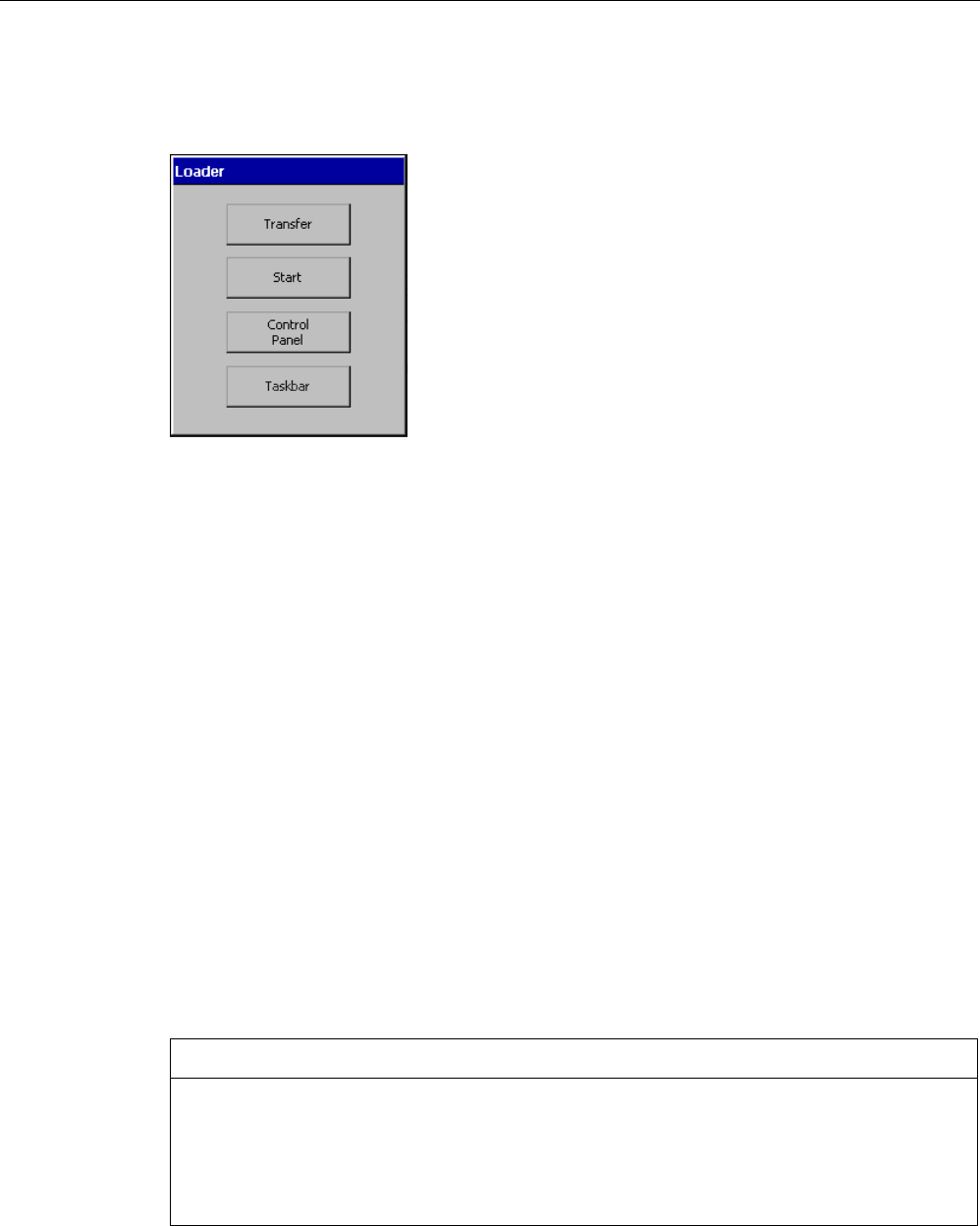
Configuring the HMI device
6.1 Desktop and Loader
Wireless Teach Pendant F IWLAN V2
98 Operating Instructions, 08/2010, A5E02453837-01
Loader
The following figure shows the Loader.
The buttons on the Loader have the following function:
● "Transfer" button – This switches the HMI device to "Transfer" mode.
The transfer mode can only be activated when at least one data channel has been
enabled for the transfer.
● "Start" button – This starts the project on the HMI device.
When you do not perform any operation, the project starts automatically based on the
settings in the Control Panel after a delay time.
● "Control Panel" button – This opens the Control Panel.
You can make a variety of settings in the Control Panel, for example, the settings for the
transfer.
● "Taskbar" button – This opens the taskbar and the Windows CE Start menu.
The Loader will reappear when the project is closed on the HMI device.
Password protection
You can protect the Control Panel and taskbar from unauthorized access.
If password protection is configured, the "secure mode" message is displayed on the
desktop. If the password is not entered, only the "Transfer" and "Start" buttons are operable.
You can find additional information on Secure Mode in the section "Enabling and disabling
SecureMode (Page 101)."
NOTICE
Keeping the password
If the password is no longer available, you are forced to update the operating system to
regain access to the Control Panel and the Windows CE taskbar.
Backup password to protect it against loss. You can find additional information on updating
the operating system in the section "Updating the operating system (Page 191)."
PRELIMINARY II
1.7.2010
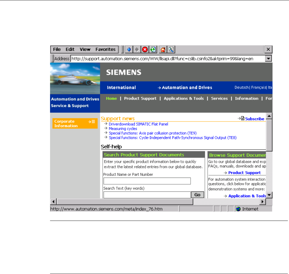
Configuring the HMI device
6.1 Desktop and Loader
Wireless Teach Pendant F IWLAN V2
Operating Instructions, 08/2010, A5E02453837-01 99
Internet Explorer
Internet Explore for Windows CE is installed on the HMI device.
Note
Internet Explorer for Windows CE and the Internet Explorer on a PC differ in terms of
functionality.
Internet Explorer for Windows CE has separate proxy settings that are independent of the
settings in the Control Panel of the HMI device.
For more detailed information, refer to the Microsoft website.
PRELIMINARY II
1.7.2010

Configuring the HMI device
6.2 Operator input options
Wireless Teach Pendant F IWLAN V2
100 Operating Instructions, 08/2010, A5E02453837-01
Status bar
When you click the icon in the status bar, the following dialog appears:
① Address type
② IP address
③ Subnet mask
④ Button for details
⑤ Button to refresh the display
The dialog contains information on the current WLAN or LAN connection
6.2 Operator input options
The following operator control options are made available for the Windows CE interface and
Control Panel:
● Touch screen
The operator controls shown in the dialogs are touch-sensitive. Touch objects are
operated in the same way as mechanical keys. You activate an operator control by
pressing on it with your finger. To double-click them, touch an operator control twice in
succession.
● Membrane keyboard
You can use the numeric area of the membrane keyboard to enter numeric values.
● USB keyboard
You can operate the Windows CE interface and Control Panel with an external keyboard
in the exact same way as you do with the screen keyboard of the HMI device.
● USB mouse
You can operate the Windows CE interface and Control Panel with an external mouse in
the exact same way as you do with the touch screen of the HMI device.
PRELIMINARY II
1.7.2010