Siemens WTPIWLAN-V200 SIMATIC WTP 277F IWLAN User Manual Wireless Teach Pendant F IWLAN V2
Siemens AG SIMATIC WTP 277F IWLAN Wireless Teach Pendant F IWLAN V2
Siemens >
Contents
- 1. Users Manual p1
- 2. Users Manual p2
- 3. Users Manual p3
Users Manual p2

Configuring the HMI device
6.3 Enabling and disabling SecureMode
Wireless Teach Pendant F IWLAN V2
Operating Instructions, 08/2010, A5E02453837-01 101
6.3 Enabling and disabling SecureMode
SecureMode prevents unauthorized access to the desktop and the taskbar of the HMI
device. In SecureMode, all functions on the desktop and the taskbar of the HMI device are
locked.
Enabling SecureMode
You have the following options for enabling SecureMode:
● Assign a password in the Control Panel for the HMI device.
● If no password has been assigned for the HMI device, double-click the following icon on
the desktop.
SecureMode is enabled. The text "secure mode" appears on the desktop.
Disabling SecureMode
You can disable SecureMode as follows:
● If a password is assigned for the HMI device, then delete it.
● If no password has been assigned for the HMI device, operate the "Taskbar" button once
in the Loader.
See also
Entering and deleting a password (Page 114)
PRELIMINARY II
1.7.2010
Configuring the HMI device
6.4 Control Panel
Wireless Teach Pendant F IWLAN V2
102 Operating Instructions, 08/2010, A5E02453837-01
6.4 Control Panel
6.4.1 Overview
You have the following options for opening the Control Panel:
● During the startup phase
Press the "Control Panel" button in the Loader.
● In the Windows CE start menu
– Double-click the following icon on the desktop:
The Start menu is displayed.
– Select "Settings > Control Panel".
The Control Panel is displayed.
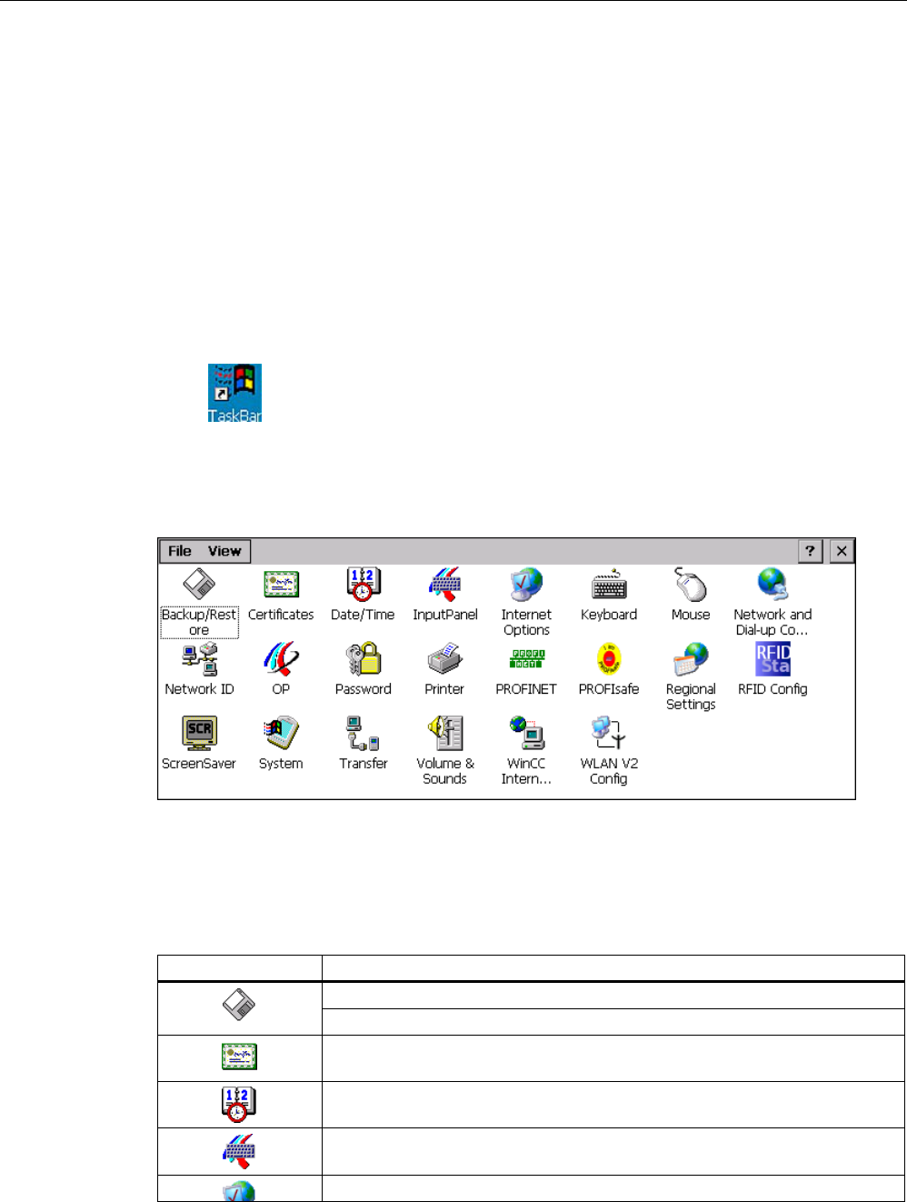
6.4.2 Functions in the Control Panel
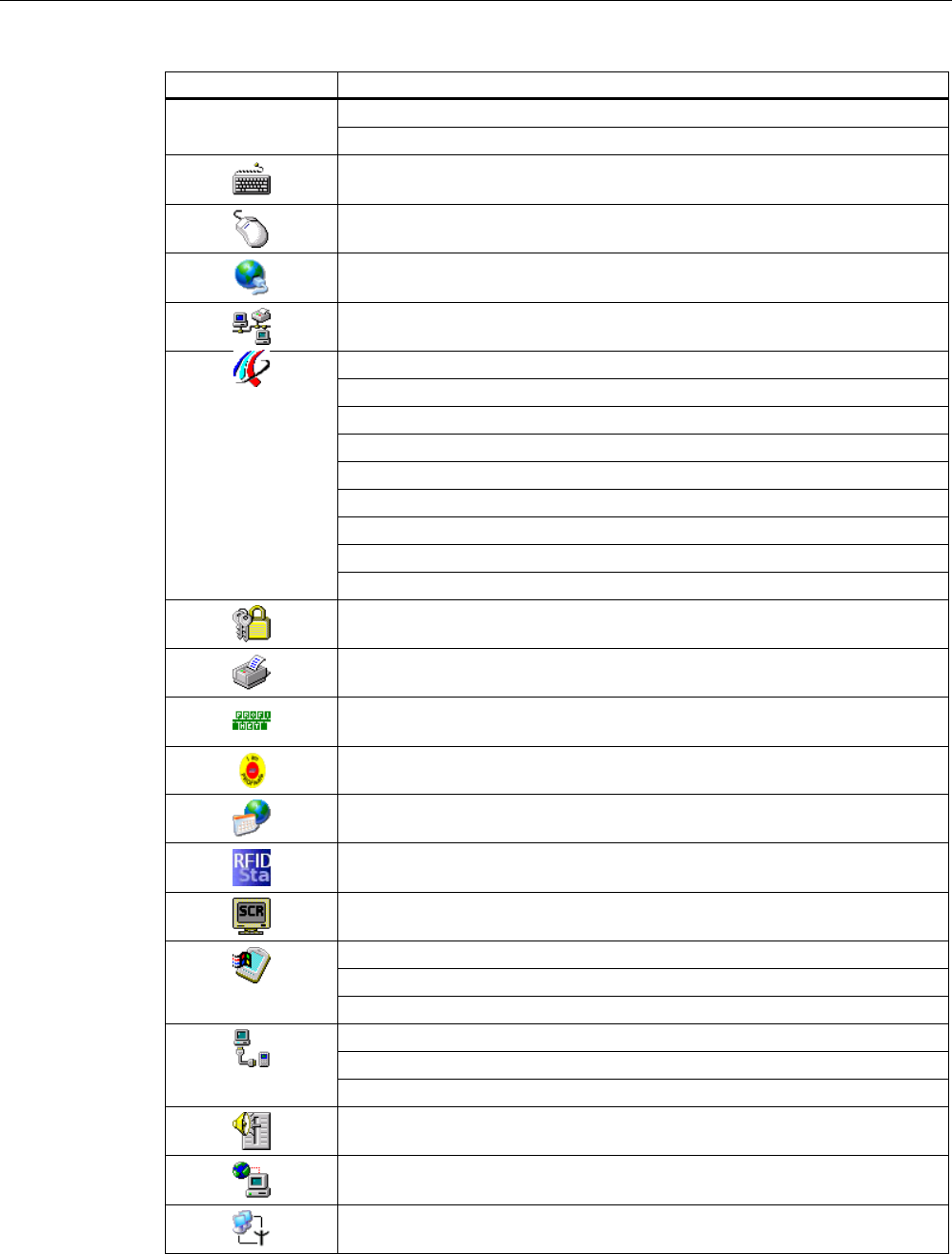
The following table shows the functions assigned to the icons in the Control Panel.
Icon Section
Saving to external storage medium – backup (Page 156)
Restoring from external storage medium – Restore (Page 157)
Importing, displaying and deleting certificates (Page 154)
Setting the date and time (Page 125)
Configuring the screen keyboard (Page 107)
Changing general settings (Page 151)
PRELIMINARY II
1.7.2010
Configuring the HMI device
6.4 Control Panel
Wireless Teach Pendant F IWLAN V2
Operating Instructions, 08/2010, A5E02453837-01 103
Icon Section
Setting the proxy server (Page 152)
Changing Internet security settings (Page 153)
Setting the character repeat rate of the screen keyboard (Page 109)
Setting the double-click (Page 110)
Specifying the IP address and name server (Page 146)
Specifying the logon data (Page 148)
Backing up registry information and temporary data (Page 133)
Changing display brightness (Page 108)
Displaying information about the HMI device (Page 135)
Starting the HMI device again (Page 113)
Display firmware (Page 137)
Calibrating the touch screen (Page 111)
Activate memory management (Page 136)
Displaying the charge status of the batteries (Page 138)
Displaying licensing information (Page 137)
Entering and deleting a password (Page 114)
Printing – not approved for the Wireless Teach Pendant F IWLAN
Enabling PROFINET IO (Page 138)
Setting the PROFIsafe address (Page 140)
Regional and language settings (Page 127)
Reassigning an RFID tag ID (Page 141)
Setting the screen saver (Page 127)
Displaying general system properties (Page 134)
Specifying the computer name of the HMI device (Page 145)
Displaying memory distribution (Page 134)
Programming the data channel (Page 142)
Setting the location of the project (Page 130)
Setting the delay time for the project (Page 131)
Enabling sound and setting sound volume (Page 132)
Configuring e-mail (Page 148)
Configuring the WLAN connection (Page 116)
PRELIMINARY II
1.7.2010

Configuring the HMI device
6.4 Control Panel
Wireless Teach Pendant F IWLAN V2
104 Operating Instructions, 08/2010, A5E02453837-01
6.4.3 Operating the Control Panel
You operate the Control Panel with the touch screen of the HMI device or a USB mouse.
Requirement
● The current project is closed.
● The loader appears.
Procedure
Proceed as follows:
1. Open the Control Panel.
2. Execute the function by double-clicking on the icon.
The corresponding dialog is displayed.
3. Open a tab.
The content of the dialog changes.
4. Press the required operator control.
5. Use the button to confirm your entries. The entry is applied.
To cancel the entry, press the button. The dialog closes.
6. Press .
The Control Panel closes. The loader appears.
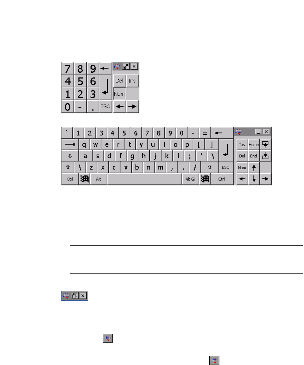
6.4.4 Using the screen keyboard in the Control Panel
If you do not use an external keyboard, use the screen keyboard to enter numeric and
alphanumeric characters. As soon as you touch a text box, a numeric or alphanumeric
screen keyboard is displayed, depending on the type of the text box.
PRELIMINARY II
1.7.2010
Configuring the HMI device
6.4 Control Panel
Wireless Teach Pendant F IWLAN V2
Operating Instructions, 08/2010, A5E02453837-01 105
Display methods for the screen keyboard
You can change the type of display for the screen keyboard and move the position on the
screen.
● Numerical screen keyboard
● Alphanumerical screen keyboard
The alphanumerical screen keyboard has the following levels.
– Normal level
– Shift level
The shift level includes uppercase letters.
– Special character level
Note
The ' character (button between ";" and "\") appears only when followed by a space. If
the ' character is followed by a letter, then the result will be an accent, such as "á".
● Reduced screen keyboard
Procedure for moving the screen keyboard
Proceed as follows:
1. Touch the icon .
2. Without lifting your finger, move the screen keyboard on the touch screen.
3. When the desired position is reached, release the icon .
PRELIMINARY II
1.7.2010
Configuring the HMI device
6.4 Control Panel
Wireless Teach Pendant F IWLAN V2
106 Operating Instructions, 08/2010, A5E02453837-01
Procedure for adjusting the size of the screen keyboard
Note
The icon only appears on the screen keyboard if in the "Siemens HMI InputPanel" dialog
you have selected the "Show Resize button" check box.
Proceed as follows:
1. Touch the icon .
2. To adjust the size of the screen keyboard, maintain contact.
3. When the size you want is reached, release contact with the icon.
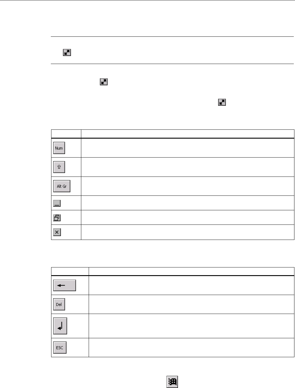
Changing the display of the screen keyboard
Key Function
Switching between the numerical and alphanumerical keyboard
Switching between the normal level and Shift level of the alphanumerical screen
keyboard
Switchover to special characters
Switching from full display to reduced display
Switching from reduced display to full display
Closing of reduced display of the screen keyboard
Entering data
Key Function
Delete character left of cursor
Delete character right of cursor
Confirm input
Cancel input
Opening the Windows CE taskbar
You open the Windows CE taskbar with the key.
PRELIMINARY II
1.7.2010
Configuring the HMI device
6.4 Control Panel
Wireless Teach Pendant F IWLAN V2
Operating Instructions, 08/2010, A5E02453837-01 107
6.4.5 Changing settings for operation
6.4.5.1 Configuring the screen keyboard
You can use this function to change the layout and the position of the screen keyboard.
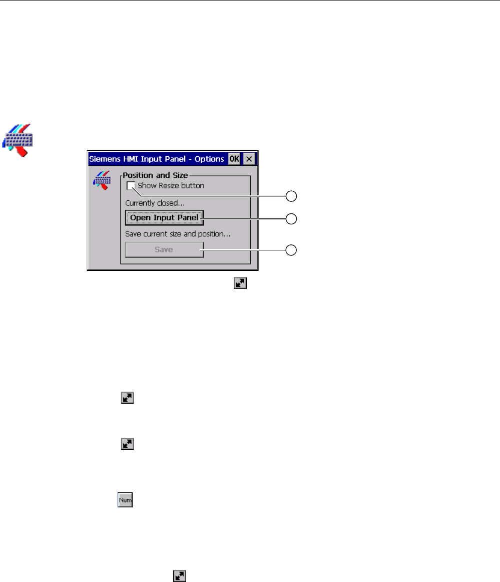
Requirement You have opened the "Siemens HMI Input Panel - Options" dialog with the "InputPanel"
icon.
① Check box for displaying the button in the screen keyboard
② Button for displaying the screen keyboard
③ Button for saving the screen keyboard settings
Procedure Proceed as follows:
1. If you want to change the size of the screen keyboard, select the "Show Resize Button"
check box.
The button is displayed in the screen keyboard you want to open.
2. If you want to prevent the size of the screen keyboard from being changed, clear the
"Show Resize Button" check box.
The button is removed from the screen keyboard you want to open.
3. You can use the "Open Input Panel" button to open the screen keyboard, see section
"Using the screen keyboard in the Control Panel (Page 104)".
4. If you want to switch between the numeric and alphanumeric screen keyboard, press
the key.
5. If you want to change the position of the screen keyboard, use the mouse pointer to
select a free space between the keys.
Release the mouse pointer when the required position has been reached.
6. If you want to increase or decrease the size of the keyboard screen, place the mouse
pointer over the button.
7. Change the size of the screen keyboard by dragging it with the mouse pointer.
8. Release the mouse pointer when the required size has been reached.
9. If you want to save the settings, press "Save".
10. Confirm your entries.
The dialog closes. The screen keyboard settings have been modified.
PRELIMINARY II
1.7.2010
Configuring the HMI device
6.4 Control Panel
Wireless Teach Pendant F IWLAN V2
108 Operating Instructions, 08/2010, A5E02453837-01
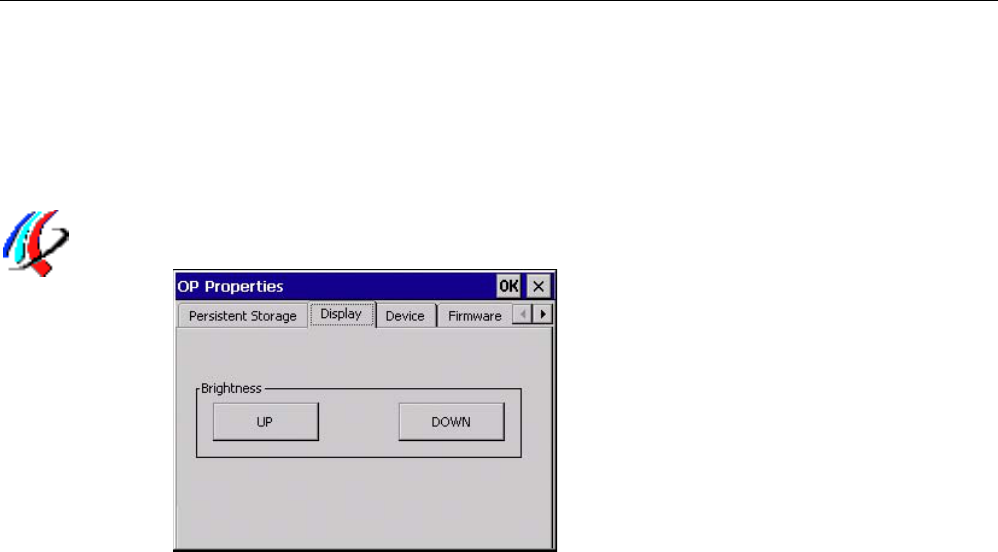
6.4.5.2 Changing display brightness
You can use this function to change the brightness of the display.
Requirement
You have opened the "Display" tab in the "OP Properties" dialog using the "OP" icon.
Procedure
Proceed as follows:
1. If you want to increase the brightness, press the "UP" button.
The brightness changes in steps each time you press the key.
2. If you want to decrease the brightness, press the "DOWN" button.
3. Confirm your entries.
The dialog closes.
Result
The brightness of the display has been changed.
PRELIMINARY II
1.7.2010
Configuring the HMI device
6.4 Control Panel
Wireless Teach Pendant F IWLAN V2
Operating Instructions, 08/2010, A5E02453837-01 109
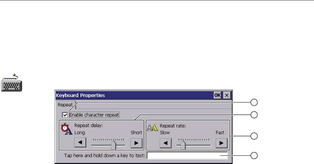
6.4.5.3 Setting the character repeat rate of the screen keyboard
You can use this function to set the character repeat and associated delay for the screen
keyboard.
Requirement
You have opened the "Keyboard Properties" dialog using the "Keyboard" icon.
① Check box for selecting the character repeat
② Slider control and buttons for the delay time before character repeat
③ Slider control and buttons for the rate of the character repeat
④ Test box
Procedure
Proceed as follows:
1. If you want to enable character repetition, select the "Enable character repeat" check box.
2. If you want to change the delay, press a button or the slider in the "Repeat delay" group.
Moving the slider to the right will shorten the delay. Moving to the left will extend the
delay.
3. If you want to change the repeat rate, press a button or the slider in the "Repeat rate"
group.
Moving the slider to the right will accelerate the repeat rate. Moving to the left will slow
down the repeat rate.
4. Check the settings for the touch control by touching the test field.
The screen keyboard is displayed.
5. Move the screen keyboard as needed.
6. Press an alphanumeric key and keep it pressed down.
Check the implementation of the character repetition and the rate of the character
repetition in the test box.
7. If the settings are not perfect, correct them.
8. Confirm your entries.
The dialog closes. The character repetition and delay are set.
PRELIMINARY II
1.7.2010
Configuring the HMI device
6.4 Control Panel
Wireless Teach Pendant F IWLAN V2
110 Operating Instructions, 08/2010, A5E02453837-01
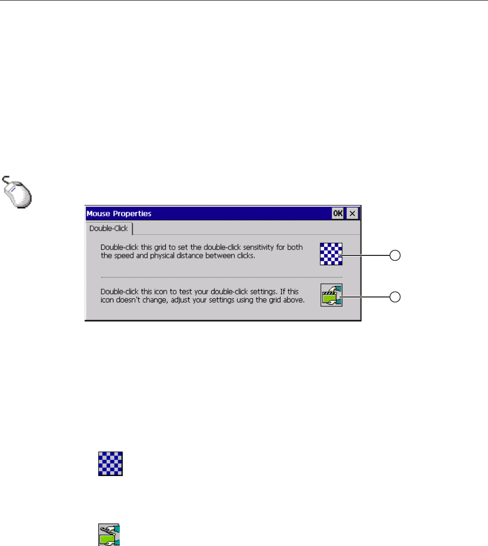
6.4.5.4 Setting the double-click
You start applications in the Control Panel and in Windows CE with a double-click. A double-
click corresponds to two brief touches.
In the "Mouse Properties" dialog, make the following adjustments for operation with the
touch screen or external mouse:
● Interval between two touch contacts on the touch screen
● Interval between the two clicks of a double-click
Requirement
You have opened the "Mouse Properties" dialog using the "Mouse" icon.
① Pattern
② Icon
Procedure
Proceed as follows:
1. Double-click the pattern.
After the double-click the grid is shown in inverse colors. White boxes become gray. The
timeframe for the double-click is saved.
2. Check the double-click.
Press on the icon twice in succession to do this. If the double-click is recognized, the icon
is displayed as follows:
3. If the settings are not perfect, correct them.
To do this, repeat steps 1 and 2.
4. Confirm your entries.
The dialog closes. The double-click adjustment is completed.
PRELIMINARY II
1.7.2010
Configuring the HMI device
6.4 Control Panel
Wireless Teach Pendant F IWLAN V2
Operating Instructions, 08/2010, A5E02453837-01 111
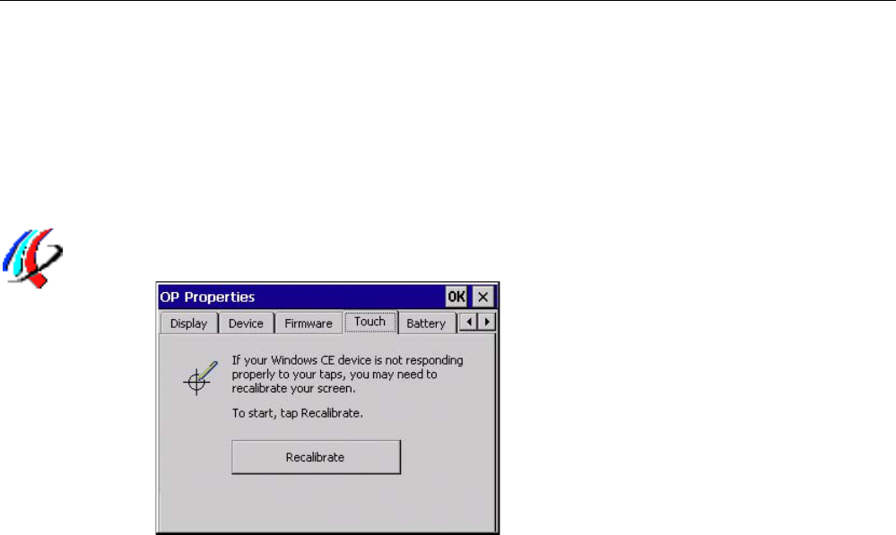
6.4.5.5 Calibrating the touch screen
Depending on the mounting position and viewing angle, parallax may occur on the touch
screen. To prevent any resulting operating errors, you may need to calibrate the touch
screen during the startup phase or during runtime.
Requirement
You have opened the "Touch" tab of the "OP Properties" dialog using the "OP" icon.
PRELIMINARY II
1.7.2010

Configuring the HMI device
6.4 Control Panel
Wireless Teach Pendant F IWLAN V2
112 Operating Instructions, 08/2010, A5E02453837-01
Procedure
Proceed as follows:
1. Press "Recalibrate".
The following dialog appears:
&DUHIXOO\SUHVVDQGEULHIO\KROGVW\OXVRQWKHFHQWHURI
WKHWDUJHW5HSHDWDVWKHWDUJHWPRYHVDURXQGWKHVFUHHQ
&DOLEUDWLRQFURVVKDLUV
2. Briefly touch the center of the calibration crosshairs.
The calibration crosshairs are then displayed at four more positions. Briefly touch the
middle of the calibration crosshairs for each position.
Once you have touched all the positions of the calibration crosshairs, the following dialog
appears:
New calibration settings have been measured.
Tape the screen to register saved data.
Wait for 30 seconds to cancel saved data and
keep the current setting.
Time limit: 30 sec
3. Touch the touch screen.
The calibration is saved. The "Touch" tab is displayed once again in the "OP Properties"
dialog. If you do not touch the touch screen within the time shown, your original setting
will be retained.
4. Close the dialog.
The touch screen of the HMI device is calibrated.
PRELIMINARY II
1.7.2010
Configuring the HMI device
6.4 Control Panel
Wireless Teach Pendant F IWLAN V2
Operating Instructions, 08/2010, A5E02453837-01 113
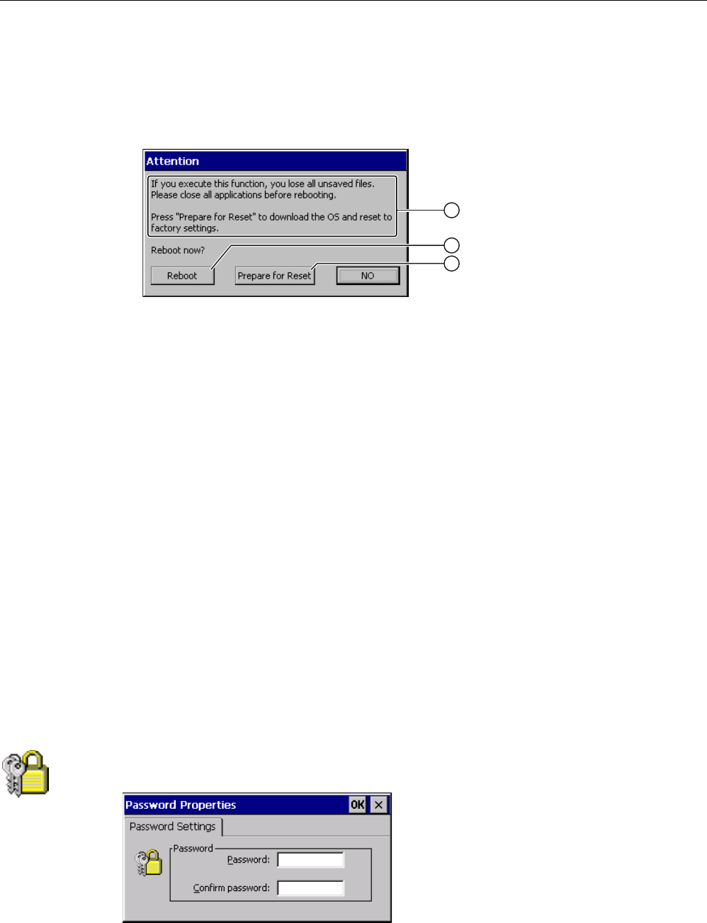
6.4.5.6 Starting the HMI device again
You need to start the HMI device again in the following situations:
● You have enabled or disabled the PROFINET IO direct keys – see section "Enabling
PROFINET IO (Page 138)".
● You have changed the time zone and activated daylight saving time – see section
"Setting the date and time (Page 125)".
● You have enabled the screen saver again – see section "Setting the screen saver
(Page 127)".
Note
All volatile data are lost when the HMI device is started again. Check the following:
The project on the HMI device is complete
No data is being written to the flash memory
Requirement
● You have opened the "Device" tab in the "OP Properties" dialog using the "OP" icon.
● If you want to restore the factory setting:
The HMI device is connected to a configuration PC via PROFINET.
PRELIMINARY II
1.7.2010
Configuring the HMI device
6.5 Entering and deleting a password
Wireless Teach Pendant F IWLAN V2
114 Operating Instructions, 08/2010, A5E02453837-01
Procedure
Proceed as follows:
1. If you want to restart the HMI device, press "Reboot".
The following message is displayed:
① If you run this function, all data which has not been backed up will be lost. Please close all
applications before restarting.
② Button for restart
③ Button for restoring factory settings and subsequent restart
2. Press one of the buttons.
● If you want to restart the HMI device, press "Reboot".
The HMI device restarts without delay.
● If you want to restore the factory settings on the HMI device and then restart, press
"Prepare for Reset".
You are given the option of restoring the factory settings on the HMI device using
ProSave. The HMI device then restarts.
● If you do not want to restart the HMI device, press "No".
The message closes. There will be no restart.
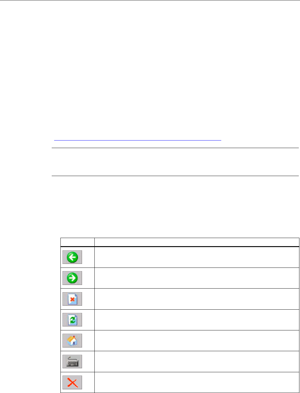
6.5 Entering and deleting a password
You can use this function to set and remove password protection. The password protection
is based on the access to the Control Panel and Windows CE taskbar.
Requirement
You have opened the "Password Properties" dialog using the "Password" icon.
PRELIMINARY II
1.7.2010

Configuring the HMI device
6.5 Entering and deleting a password
Wireless Teach Pendant F IWLAN V2
Operating Instructions, 08/2010, A5E02453837-01 115
NOTICE
Keeping the password
If the password is no longer available, you have no access to the Control Panel and the
Windows CE taskbar.
Backup password to protect it against loss.
Procedure for configuring a password
Note
The following characters are prohibited in passwords:
Blank
The two special characters ' "
Proceed as follows:
1. Enter a password in the "Password" text box.
2. Repeat the password entry in the "Confirm password" text box.
3. Confirm your entries.
The dialog closes.
Result
You cannot open the Control Panel or Windows CE taskbar without entering a password.
SecureMode is enabled.
Procedure for removing a password
Proceed as follows:
1. Delete the information in the "Password" and "Confirm password" text boxes.
2. Confirm your deletions.
The dialog closes.
Result
Password protection for the Control Panel and Windows CE taskbar has been removed.
There is no open access to the Control Panel and Windows CE taskbar.
SecureMode is disabled.
See also
Enabling and disabling SecureMode (Page 101)
PRELIMINARY II
1.7.2010
Configuring the HMI device
6.6 Configuring the WLAN connection
Wireless Teach Pendant F IWLAN V2
116 Operating Instructions, 08/2010, A5E02453837-01
6.6 Configuring the WLAN connection
Similar to an access point, you configure the WLAN parameters of the HMI device in Web
Based Management. You have the following options for configuration:
● Setting the parameters for WLAN communication using wizards.
● Advanced settings for all parameters in the "System", "Interfaces", "Security" and
"I-Features" menus.
This section describes:
● Setting the WLAN parameters using wizards
● Setting the iPCF-MC parameters for rapid roaming in the "I-Features" menu of
Web Based Management.
You can find a full description of all advanced settings with all WLAN parameters in
"SCALANCE W-700" configuration manual
(http://support.automation.siemens.com/WW/view/en/32816761).
Note
Set the parameters for all access points that communicate with the HMI device before you
begin configuration of the WLAN connection of the HMI device.
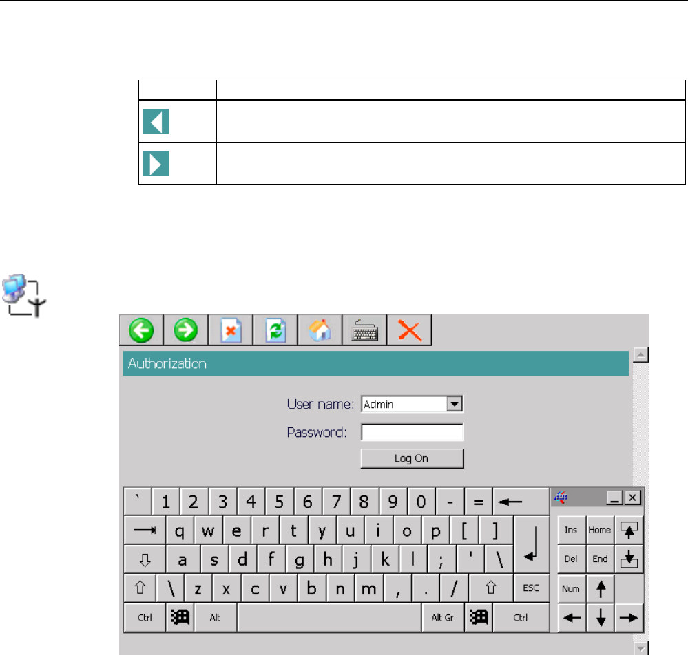
Buttons in Web Based Management
The following buttons are provided in Web Based Management of the HMI device to facilitate
data input:
● Browser buttons
Button Function in Web Based Management
One page back
One page forward
Stop loading page
Refresh page
Go to home page
Open screen keyboard for data input
Close Web Based Management
PRELIMINARY II
1.7.2010
Configuring the HMI device
6.6 Configuring the WLAN connection
Wireless Teach Pendant F IWLAN V2
Operating Instructions, 08/2010, A5E02453837-01 117
● Buttons to display and hide the menu tree
Icon Function
Hiding the menu tree
Displaying the menu tree
When you start one of the wizards in the menu tree, the menu tree will automatically be
minimized.
Requirement
You have opened the "Authorization" dialog using the "WLAN Settings" icon.
PRELIMINARY II
1.7.2010
Configuring the HMI device
6.6 Configuring the WLAN connection
Wireless Teach Pendant F IWLAN V2
118 Operating Instructions, 08/2010, A5E02453837-01
Procedure
Proceed as follows:
1. If you want to change settings of the WLAN device, select the "Admin" entry in the
"User name" selection box.
If you select the "User" entry, you only have read access to the configuration data of the
WLAN device.
Enter your password. If no password is set, the default passwords of the factory state will
be in effect:
– If you have selected "Admin", enter "admin".
– If you have selected "User", enter "user".
2. Press "Log On".
Logon starts.
Note
The password for the "admin" user is different for the U.S. version of the WLAN device.
You can obtain the required password from the Siemens support personnel.
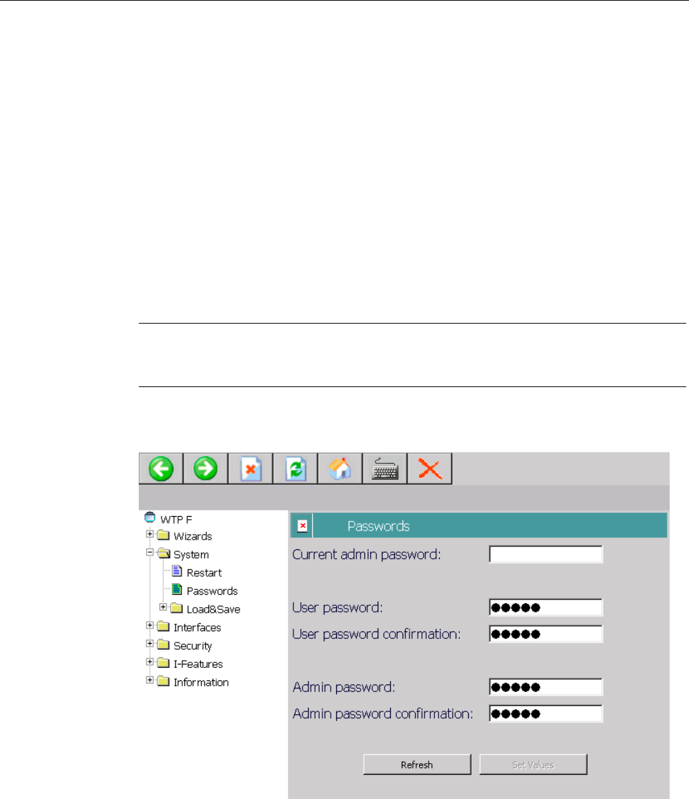
3. After initial logon as "Admin", change the password for the administrator under "System >
Passwords".
The password may consist of up to 31 characters.
The ASCII code 0x20 to 0x7e is used for creating passwords.
PRELIMINARY II
1.7.2010
Configuring the HMI device
6.6 Configuring the WLAN connection
Wireless Teach Pendant F IWLAN V2
Operating Instructions, 08/2010, A5E02453837-01 119
The following characters are supported:
– Numbers 0 to 9
– Letters abcdefghijklmnopqrstuvwxyz ABCDEFGHIJKLMNOPQRSTUVWXYZ
– The special characters !$"#%&'()*+,-./:;<=>?@[\]^_`{|}~ and the space character
4. Apply the settings with the "Set Value" button.
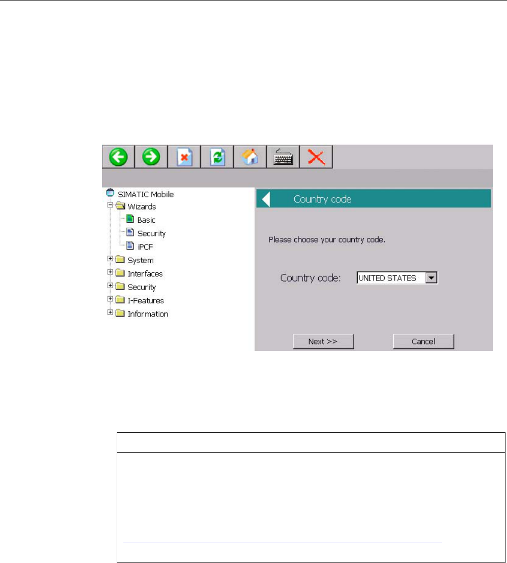
5. Select "Wizards > Basic".
Make the following settings in the "Basic" Wizard. Go to the next text window using the
"Next" button.
– Selection list "Country Code"
Select the country in which you are operating the HMI device. The corresponding
channel allocation and setting for power level is automatic.
NOTICE
Country code
The country setting is required for operation complying with the approvals. Selecting
a country that does not match the country in which the HMI device is being used can
have criminal consequences. The national approvals for the HMI device are listed on
the back of the device and in the product information for
"Wireless Teach Pendant F IWLAN" in the Internet
(http://support.automation.siemens.com/WW/view/en/30360848/133300).
Under "Country code", select the country in which you are operating the HMI device.
– "Connect to any SSID" check box
If this box is checked, the HMI device connects to the access point which provides the
best possible data transfer and to which a connection is permitted based on the
security settings specified under "Security".
– "SSID" text box
PRELIMINARY II
1.7.2010
Configuring the HMI device
6.6 Configuring the WLAN connection
Wireless Teach Pendant F IWLAN V2
120 Operating Instructions, 08/2010, A5E02453837-01
Enter the name of the network in this text box. The network name must match the
network name that is entered in the configuration of access points, with which the HMI
device communicates.
Note
The HMI device allows the use of all characters except the percent sign for the SSID.
For reasons of compatibility, do not use language-specific characters such as German
umlauts or special characters. The character string for the SSID may not contain more
than 32 characters.
– Selection list "Wireless mode"
Use the transfer procedure, which is set in the configuration of access points, with
which the HMI device communicates.
– "Outdoor Client mode" check box
You can use the HMI device to operate in either indoor or outdoor mode. In indoor
mode, all nationally approved channels and power levels for operation in a building
are available. In outdoor mode, the selection of country-specific channels and power
levels for operation outdoors is restricted.
Select the "Outdoor Client mode" check box if you want to operate the HMI device
outdoors.
6. Press "Finish".
The settings in the "Basic" Wizard are saved.
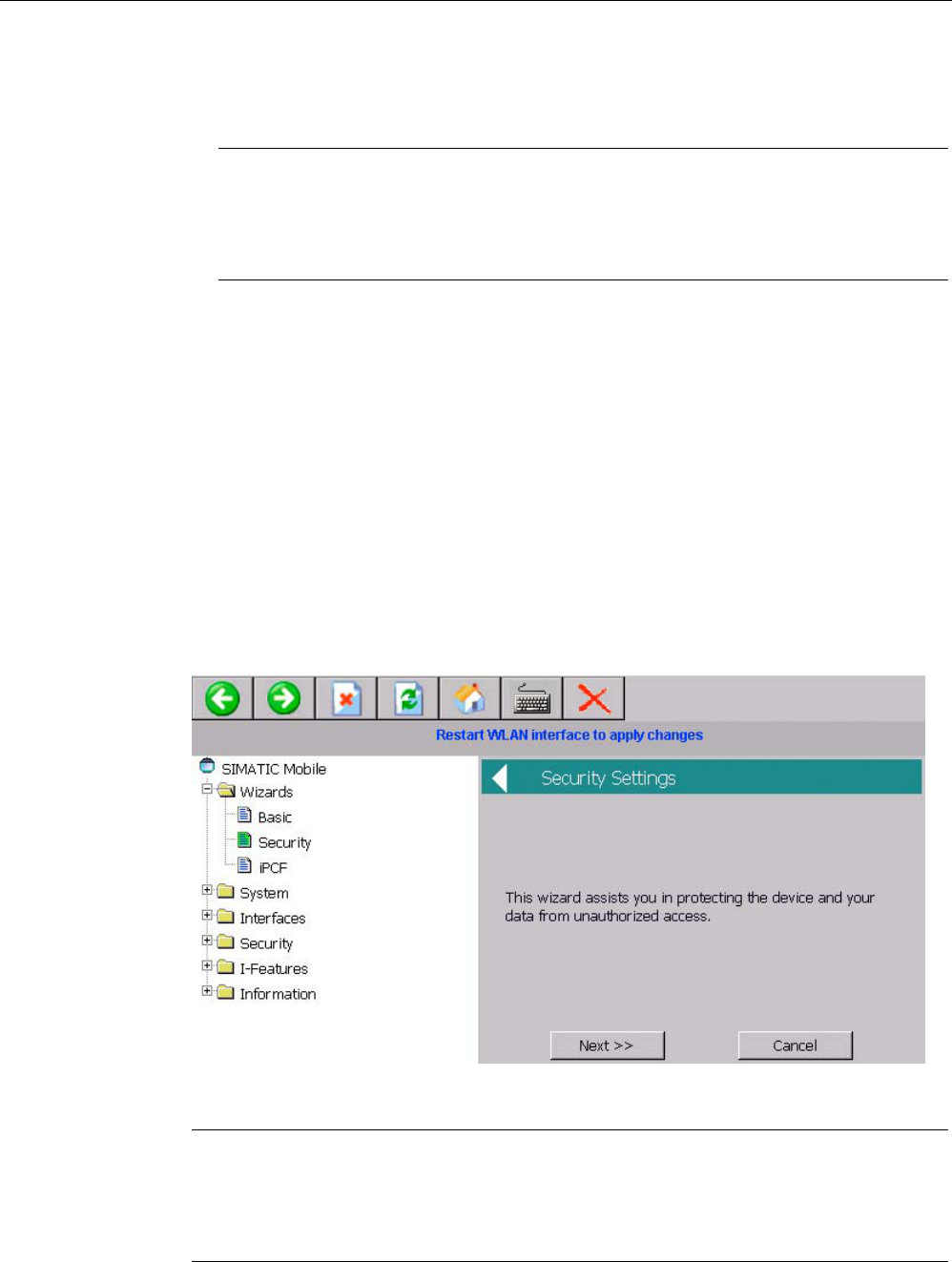
7. Select "Wizards > Security".
The Security Wizard enables you to set security-related parameters without detailed
knowledge of security technologies in wireless networks.
Note
The HMI device can be operated without configuration of security-related parameters.
Depending on the properties of your network, this will increase the risk of unauthorized
access. Therefore, go through every page of the Security Wizard to enable the basic
security features.
PRELIMINARY II
1.7.2010
Configuring the HMI device
6.6 Configuring the WLAN connection
Wireless Teach Pendant F IWLAN V2
Operating Instructions, 08/2010, A5E02453837-01 121
In the "Security" Wizard, apply the following settings from the configuration of access
points, with which the HMI device communicates.
– Select the security level for the WLAN from the "Security level" selection list.
For information about the individual security levels, refer to "SCALANCE W-700"
configuration manual
(http://support.automation.siemens.com/WW/view/en/32816761).
– Select the encryption method from the "Cipher" selection list.
The encryption protects the data to be transferred from interception and manipulation.
You can disable encryption in the "Encryption" option box only if you have selected
"Open System" for authentication in the "Basic WLAN" menu. All other security
procedures include both authentication and encryption.
– If you have selected a security level that requires a key, specify the initialization key in
the "Pass phrase" text box.
Go to the next input window using the "Next" button.
8. Press "Finish".
The settings in the "Security" Wizard are saved.
9. If you want to operate the HMI device in the "iPCF mode (industrial Point Coordination
Function)", select "Wizards > iPCF".
Go directly to Step 10 if you intend to operate the HMI device in "iPCF-MC" mode.
iPCF and iPCF-MC are mutually incompatible and cannot be used simultaneously for an
HMI device.
PRELIMINARY II
1.7.2010

Configuring the HMI device
6.6 Configuring the WLAN connection
Wireless Teach Pendant F IWLAN V2
122 Operating Instructions, 08/2010, A5E02453837-01
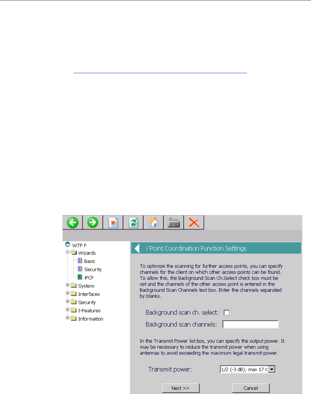
Set the parameters required for iPCF in the "iPCF" Wizard. Use the respective
parameters to improve roaming times and reduce the interference from other systems or
segments.
– "Background scan ch. select" check box
The "Background scan ch. select" check box limits the number of channels the HMI
device scans to find an access point. The result is faster handover times and reduced
risk of a real-time violation.
If you have enabled the "Background scan ch. select" option, you have to specify the
channels with access points within range that are in iPCF mode in the following
"Background scan channels" text box. If you do not define the channels, the HMI
device will have to perform a time-consuming scan of the entire band.
– "Background scan channels" text box
Here you specify the channels in which there are actually access points in iPCF mode
within the range of the HMI device. If you specify several channels, the individual
entries have to be separated by spaces.
– Selection list "Transmit power"
When using antennas, it may be necessary to reduce the transmission power so as
not to exceed the maximum statutory power or to restrict the visibility of the radio field.
If necessary, select the level of reduced transmission power here.
A reduction in the transmission power may also be necessary to avoid interference of
other radio cells, because a lower power level will result in a smaller cell.
– Selection list "Security level"
Use this field to select the required level of security for your wireless network. The
security level must match the setting of an access point in iPCF mode, with which the
HMI device communicates.
You have the following options:
● None (No Encryption) An open system without encryption.
● Medium (Encryption) Static keys are used. This is the recommended setting,
whereby you should use a 128-bit key.
Go to the next text window using the "Next" button.
10. Press "Finish".
The iPCF Wizard closes. You need to restart the WLAN connection to apply the settings,
see step 12.
PRELIMINARY II
1.7.2010
Configuring the HMI device
6.6 Configuring the WLAN connection
Wireless Teach Pendant F IWLAN V2
Operating Instructions, 08/2010, A5E02453837-01 123
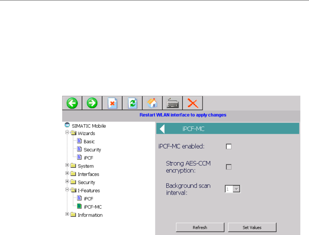
11. If you want to operate the HMI device in the "iPCF-MC mode (industrial Point
Coordination Function with Management Channel)" for rapid roaming, select "I-Features
> iPCF-MC".
iPCF was developed to achieve fast handover times when moving between radio cells.
However, iPCF achieves optimum performance only with RCoax cables. The iPCF-MC
procedure provides fast handover times, even for freely mobile clients and numerous
cells or when a large number of channels is used.
iPCF and iPCF-MC are incompatible and cannot be used simultaneously for an HMI
device.
Make the following settings in the "iPCF-MC" menu.
– Select the "iPCF-MC enabled" check box.
– Select the "Strong AES-CCM" check box if you want to use "Strong AES-CCM"
encryption.
The AES-CCM encryption method is only possible in iPCF mode. Make sure that a
128-bit WEP key is defined with the "Security > Keys" menu command. After you have
selected the "Strong AES-CCM encryption" check box, the display changes to "128 bit
AES" in the "Security > Keys" menu command. The device uses AES-CCM.
– Enter a value for "Background scan interval".
This parameter determines the time between two background scans of the HMI
device. The setting is made in iPCF cycles.
For example, if you select two, the client performs a background scan only every
second iPCF cycle. A small value for the background scan interval is the basis for fast
roaming. However, high throughput cannot be achieved with this setting. A high value
should be selected for higher data throughput.
Apply the settings with the "Set Values" button.
PRELIMINARY II
1.7.2010
Configuring the HMI device
6.6 Configuring the WLAN connection
Wireless Teach Pendant F IWLAN V2
124 Operating Instructions, 08/2010, A5E02453837-01
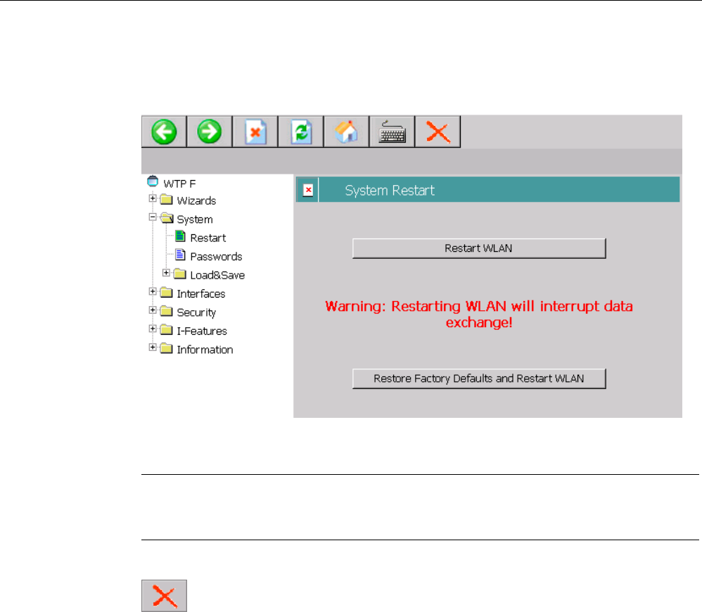
12. Select "System > Restart".
You can use the "Restart WLAN interface to apply changes" link for quick navigation to
this menu command.
13. Press "Restart WLAN".
The restart of the WLAN interface is performed.
Note
The "Restore Factory Defaults and Restart WLAN" button resets all parameters of the
WLAN interface to their factory state. The WLAN interface is then restarted.
14. Close Web Based Management with the "Exit" button.
Result
The WLAN connection was configured. When the configuration of the access points and
wireless HMI device match, the wireless connection is successfully established.
The MAC address of the HMI device is registered in the access point under the menu
command "Inform > Wireless > Client List".
PRELIMINARY II
1.7.2010
Configuring the HMI device
6.7 Changing and displaying general settings
Wireless Teach Pendant F IWLAN V2
Operating Instructions, 08/2010, A5E02453837-01 125
6.7 Changing and displaying general settings
6.7.1 Setting the date and time
You can use this function to set the date and time. The HMI device has an internal buffered
clock.
Requirement
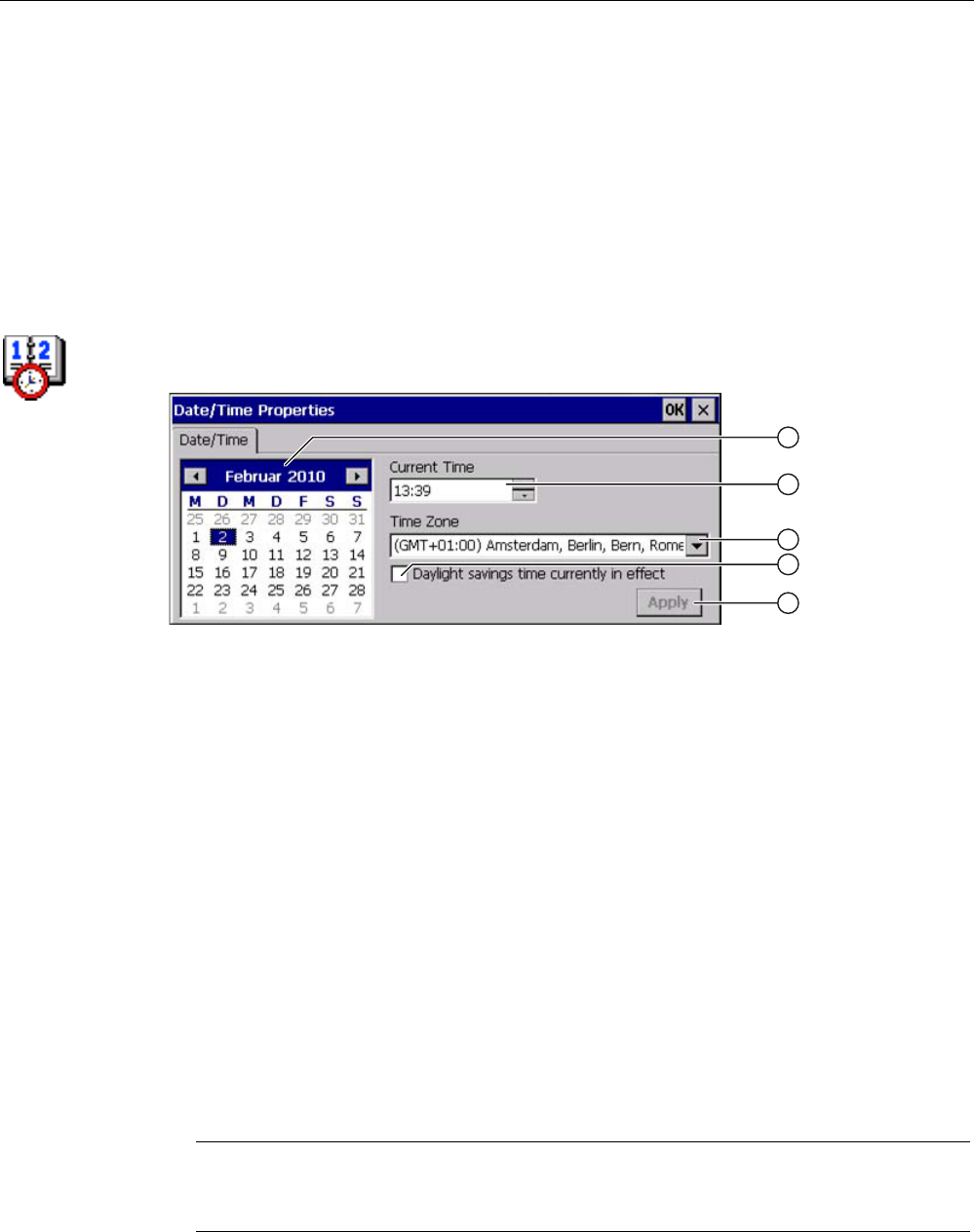
You have opened the "Date/Time Properties" dialog using the "Date/Time Properties" icon.
① Date selection box
② Text box for the time
③ Time zone selection box
④ Check box used to activate daylight saving time
⑤ Button for applying changes
Procedure
Proceed as follows:
1. Select the applicable time zone for the HMI device from the "Time Zone" selection box.
2. Press "Apply".
The time of day shown in the "Current Time" box is adjusted correspondingly to the
selected time zone.
3. Set the date in the selection box.
4. Set the current time of day in the "Current Time" text box.
5. Press "Apply".
The entry is made.
Note
The system does not automatically switch between standard time and daylight saving
time.
PRELIMINARY II
1.7.2010

Configuring the HMI device
6.7 Changing and displaying general settings
Wireless Teach Pendant F IWLAN V2
126 Operating Instructions, 08/2010, A5E02453837-01
6. If you want to switch from winter to summer time, select the
"Daylight savings time currently in effect" check box.
When you press the "Apply" button, the time is brought forward by one hour.
7. If you want to switch from summer to winter time, clear the
"Daylight savings time currently in effect" check box.
When you press the "Apply" button, the time is moved backwards by one hour.
8. Confirm your entries.
The dialog closes.
Result
The settings for the data and time of day have now been changed.
The HMI device must be restarted after changes in the following cases:
● You have changed the time zone setting
● You have changed the "Daylight savings time currently in effect" check box setting
See section "Starting the HMI device again (Page 113)".
Synchronizing the date and time with the PLC
The date and time of the HMI device can be synchronized with the PLC if this has been
configured in the project and the PLC program.
You can find additional information in the "WinCC flexible" system manual.
NOTICE
Synchronizing the date and time
If the data and time is not synchronized and time-based reactions are triggered by the HMI
device, malfunctions in the PLC may occur.
Synchronize the date and time if time-based reactions are triggered in the PLC.
PRELIMINARY II
1.7.2010
Configuring the HMI device
6.7 Changing and displaying general settings
Wireless Teach Pendant F IWLAN V2
Operating Instructions, 08/2010, A5E02453837-01 127
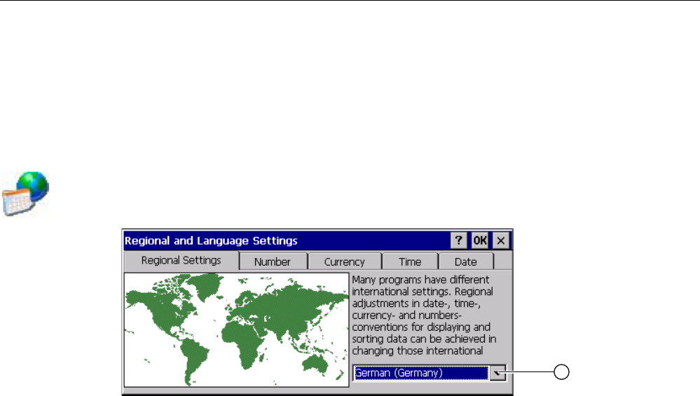
6.7.2 Regional and language settings
Information such as the date, time and decimal points are displayed differently in different
countries. You can adapt the display format to meet the requirements of various regions.
The country-specific settings apply to the current project. If the project language is changed,
the country-specific settings are also changed.
Requirement
You have opened the "Regional Settings" tab in the "Regional and Language Settings"
dialog box using the "Regional Settings" icon.
Procedure Proceed as follows:
1. Select the region from the selection box ①.
2. Navigate to the "Number", "Currency", "Time" and "Date" tabs one after the other.
3. Set the required regional settings in the selection field of these tabs.
4. Confirm your entries.
The dialog closes.
Result The required regional settings for the HMI device have been changed.
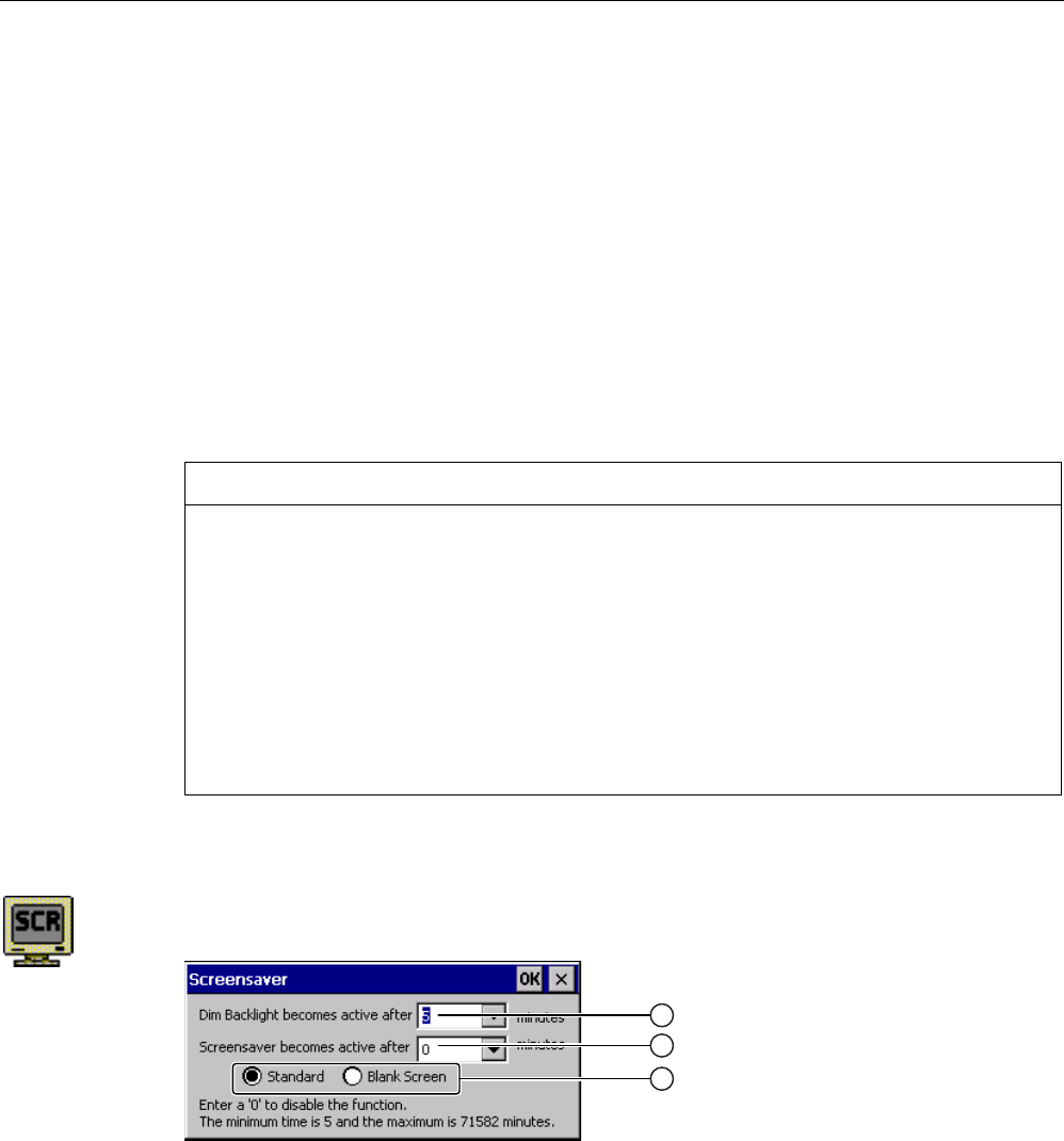
6.7.3 Setting the screen saver
Power management settings in the WinCC flexible project
To save power, the HMI device has a power management function with the following states:
● "Power Save 1"
● "Power Save 2"
The relevant time intervals are set in the WinCC flexible project. Power management is
automatically activated if the HMI device is not operated within the specified period of time.
You can clear the "Power Save 1" state by pressing the touch screen.
You can clear the "Power Save 2" state by briefly pressing the ON/OFF button.
PRELIMINARY II
1.7.2010
Configuring the HMI device
6.7 Changing and displaying general settings
Wireless Teach Pendant F IWLAN V2
128 Operating Instructions, 08/2010, A5E02453837-01
Settings in the Control Panel
In addition to the settings in the WinCC flexible project, you can set the following time
periods in the Control Panel:
● For the automatic activation of the screen saver
● For the automatic reduction in the display's backlighting.
The screen saver and backlighting are automatically activated if the display is not touched
within the specified period of time.
The screen saver switches off with the following events:
● By touching the touch screen
The reduction of the backlighting is also canceled. The function assigned to the button is not
triggered in this case.
NOTICE
Reducing backlighting
The brightness of the backlighting decreases incrementally during its operational life.
You can activate backlighting reduction to not shorten the service life of the backlighting
unnecessarily.
Activating the screen saver
The display contents that do not change for long periods can remain dimly visible in the
background. This effect is reversible, however.
Activate the screen saver. When the screen saver is active, the backlighting is also
reduced.
Requirement
You have opened the "Screensaver" dialog using the "ScreenSaver" icon.
① Time interval in minutes until backlighting is reduced
② Period of time in minutes before the screen saver is activated
③ Option buttons for the screensaver
PRELIMINARY II
1.7.2010

Configuring the HMI device
6.7 Changing and displaying general settings
Wireless Teach Pendant F IWLAN V2
Operating Instructions, 08/2010, A5E02453837-01 129
Procedure
Proceed as follows:
1. Enter the interval in minutes after which the backlighting is to be reduced. With reduced
backlighting, the HMI device operates in the "Power Save 1" mode.
Note
If a time is set for activating "Power Save 1" mode, the setting in Control Panel is only
effective when the configured time is shorter than the time set in the project for
"Power Save 1" mode.
The value "0" in the Control Panel means:
– If a time for activation of "Power Save 1" mode is specified in the project, this time
period will be applied.
– If no time is specified in the project for activation of "Power Save 1" mode, reduced
backlighting will be disabled.
2. Enter the number of minutes before the screen saver is to be activated.
The minimum time is 5 minutes and the maximum time is 71582 minutes.
Entering "0" disables the screen saver.
3. Select the type of screen saver:
– Use the "Standard" option to enable the default screen saver for Windows CE.
– Use the "Blank Screen" option to enable an empty screen as the screen saver.
4. Confirm your entries.
The dialog closes.
Result
The screen saver and the reduced backlighting for the HMI device is set. You need to restart
the HMI device after you have reset the screen saver. The selection of the screen saver
takes effect following a restart.
See also
Power management (Page 87)
Starting the HMI device again (Page 113)
PRELIMINARY II
1.7.2010
Configuring the HMI device
6.7 Changing and displaying general settings
Wireless Teach Pendant F IWLAN V2
130 Operating Instructions, 08/2010, A5E02453837-01
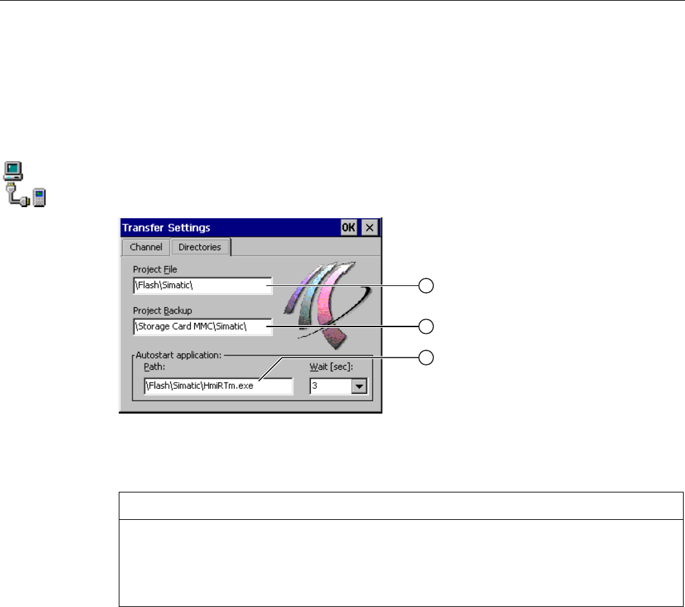
6.7.4 Setting the location of the project
There are various storage locations available for storing the compressed source file of your
project. The following describes how you can set the storage location.
Requirement
You have opened the "Directories" tab in the "Transfer Settings" dialog box using the
"Transfer" icon.
① Directory where the project file is saved
② Directory where the compressed source file of your project is saved
③ Storage location and initialization file of the HMI device for process operation
NOTICE
Project does not start
If you change the entry in the "Project File" and "Path" text boxes, the project may not open
the next time the HMI device starts.
Do not change the entries in the "Project File" and "Path" text boxes.
Procedure
Proceed as follows:
1. Select a memory location from the "Project Backup" text box.
The storage location can be a memory card or a location in the local network. During the
next backup process, the project's source file is stored in the specified location.
2. Confirm your entries.
The dialog closes.
Result
The storage location for the HMI device is now set.
PRELIMINARY II
1.7.2010
Configuring the HMI device
6.7 Changing and displaying general settings
Wireless Teach Pendant F IWLAN V2
Operating Instructions, 08/2010, A5E02453837-01 131
6.7.5 Setting the delay time for the project
You can use this function to set a delay time. The delay time determines how long the loader
appears after the HMI device starts and before the project opens.
Requirement
You have opened the "Directories" tab in the "Transfer Settings" dialog box using the
"Transfer" icon.
NOTICE
Project does not start
If you change the entry in the "Project File" and "Path" text boxes, the project may not open
the next time the HMI device starts.
Do not change the entries in the "Project File" and "Path" text boxes.
Procedure
Proceed as follows:
1. Select the desired delay time in seconds from the "Wait [sec]" selection box.
The project starts immediately with the value "0".
Note
To launch the Loader after the project opens, an operator control must be configured in
the project with the "Close project" function.
2. Confirm your entries.
The dialog closes.
Result
The delay time for the HMI device is now set.
PRELIMINARY II
1.7.2010
Configuring the HMI device
6.7 Changing and displaying general settings
Wireless Teach Pendant F IWLAN V2
132 Operating Instructions, 08/2010, A5E02453837-01
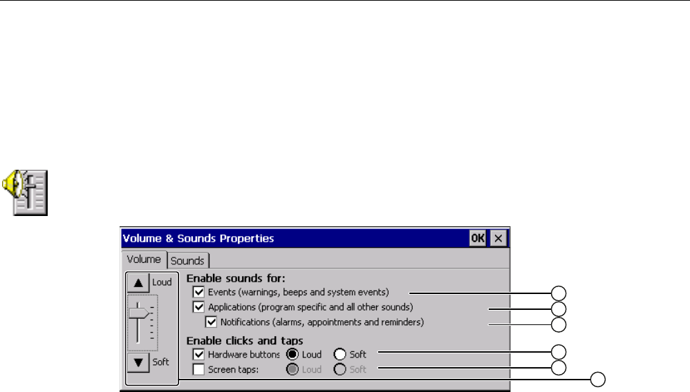
6.7.6 Enabling sound and setting sound volume
You can use this function to activate messages and acoustic feedback for input from the
membrane keyboard and touch screen. An acoustic signal is emitted with each touch or
pressing of a key.
Requirement
You have opened the "Volume" tab in the "Volume & Sounds Properties" dialog box using
the "Volume & Sounds" icon.
① Acoustic signal for warnings and system events
② Program-specific acoustic signal
③ Acoustic signal for notification
④ Acoustic feedback when using keys
⑤ Acoustic feedback when using touch screen
⑥ Keys and slide control for setting of volume for acoustic signals in the "Enable sounds for"
group
Procedure
Proceed as follows:
1. Select the check boxes needed in the "Enable sounds for" group.
If no check boxes are selected, no acoustic signal is emitted.
2. If you want an acoustic signal to be audible when input is made, select the following
check box:
– Procedure using the keys: "Hardware buttons".
– Procedure using the touch screen: "Screen taps".
3. Use the "Loud" and "Soft" radio buttons to select between loud and quiet signaling.
4. If you want to change the volume of the acoustic signal system for warnings and system
events, use the slider or the "Loud" and "Soft" buttons.
5. Confirm your entries.
The dialog closes.
Result The acoustic signals are set for acoustic operation feedback.
PRELIMINARY II
1.7.2010
Configuring the HMI device
6.7 Changing and displaying general settings
Wireless Teach Pendant F IWLAN V2
Operating Instructions, 08/2010, A5E02453837-01 133
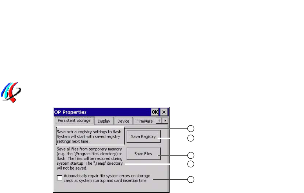
6.7.7 Backing up registry information and temporary data
You can install and remove your own programs on the HMI devices under Windows CE. You
need to back up the registry settings to flash memory after installation or removal.
You can also save the data in the memory buffer to flash memory.
Requirement
You have opened the "Persistent Storage" tab in the "OP Properties" dialog using the
"OP" icon.
① Backs up the current registry information to the flash memory. The HMI device loads the
saved registry information the next time it boots.
② Button for saving registry information
③ Button for saving temporary files
④ Backs up all the files in temporary storage to the flash memory (for example, from the
"Program Files" directory). These files are written back when the HMI device is started. The
"\Temp" directory is not saved.
⑤ Automatically repairs the file system errors on the memory card when the HMI device starts up
and when a memory card is inserted.
Procedure
Proceed as follows:
1. If you want the file system errors to be repaired automatically, select the "Automatically
repair file system errors ..." check box.
If the check box is cleared, the file system will only be repaired after prompting.
2. Click the necessary buttons.
3. Confirm your entries.
The dialog closes.
Result
At the next startup, the HMI device will use the registry entries and temporary files and the
specifications they contain.
PRELIMINARY II
1.7.2010
Configuring the HMI device
6.7 Changing and displaying general settings
Wireless Teach Pendant F IWLAN V2
134 Operating Instructions, 08/2010, A5E02453837-01
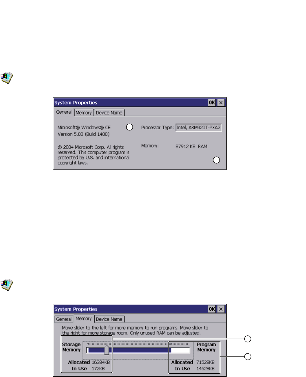
6.7.8 Displaying general system properties
Use this function to display the general system information relating to the operating system,
processor and memory.
Requirement
You have opened the "General" tab in the "System Properties" dialog box using the "System"
icon.
① Information on the version and copyright of Microsoft Windows CE
② Details on processor and size of internal Flash memory
The displayed data relates to the specific device. The information ② may therefore deviate
from this HMI device.
6.7.9 Displaying memory distribution
You can use this function to display the allocation and thereby the size of the individual
memory areas on the HMI device.
Requirement
You have opened the "Memory" tab in the "System Properties" dialog using the
"System" icon.
① Cache memory, available and used
② RAM, available and used
PRELIMINARY II
1.7.2010
Configuring the HMI device
6.7 Changing and displaying general settings
Wireless Teach Pendant F IWLAN V2
Operating Instructions, 08/2010, A5E02453837-01 135
NOTICE
Malfunction possible
If you change the allocation of the memory, malfunctions may occur.
Do not change the memory allocation in the "Memory" tab.
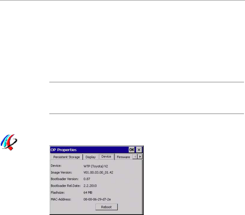
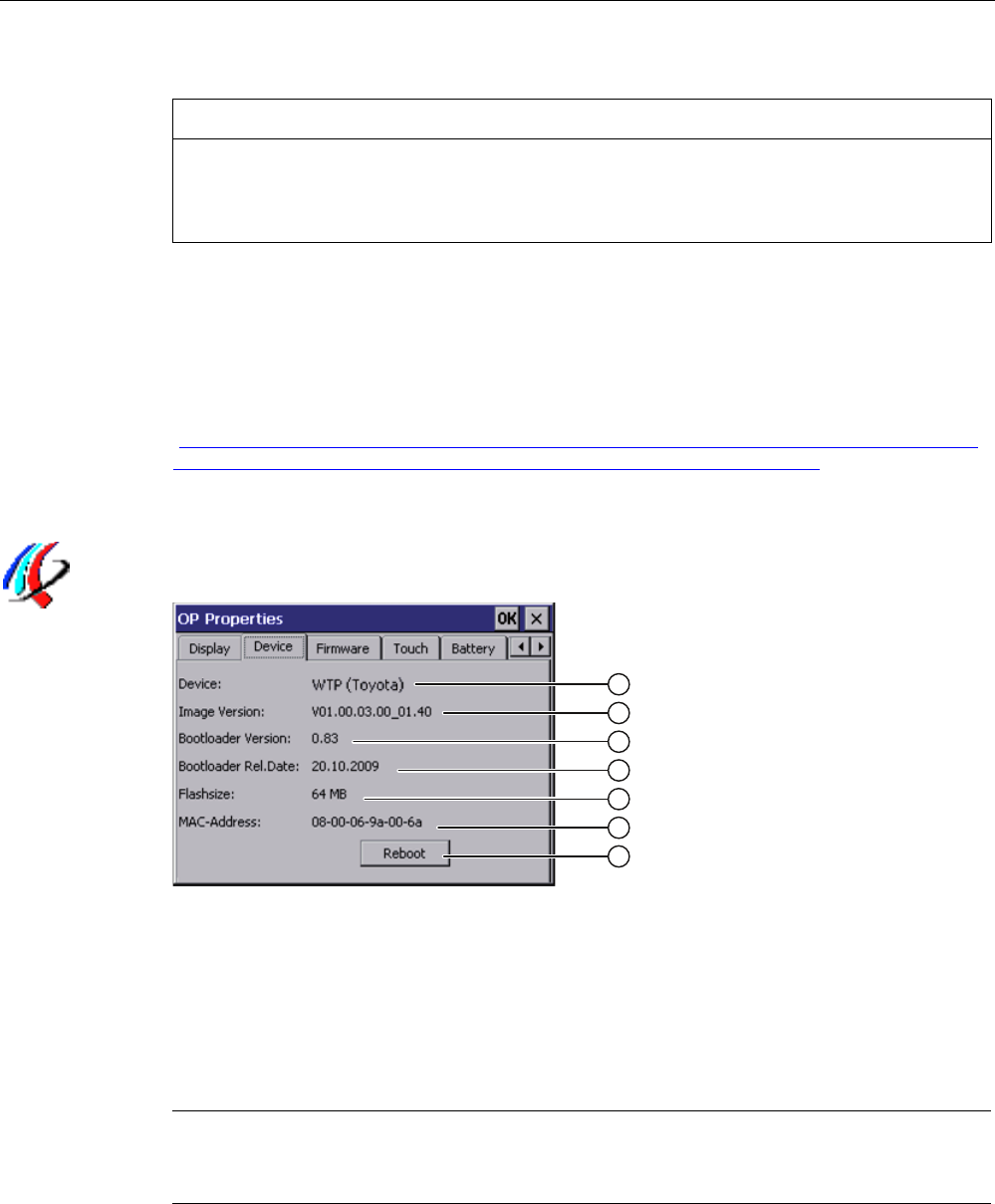
6.7.10 Displaying information about the HMI device
You can use this function to display device-specific information. You will need this
information if you contact Technical Support
(http://support.automation.siemens.com/WW/llisapi.dll?aktprim=99&lang=en&referer=%2fW
W%2f&func=cslib.csinfo2&siteid=csius&extranet=standard&viewreg=WW).
Requirement
You have opened the "Device" tab in the "OP Properties" dialog using the "OP" icon.
① HMI device name
② Version of the HMI device image
③ Version of the boot loader
④ Boot loader release date
⑤ Size of the internal flash memory in which the HMI device image and project are stored
⑥ MAC address of the HMI device
⑦ See section "Starting the HMI device again (Page 113)."
Note
The size of the internal flash memory does not correspond to the available working memory
for a project.
PRELIMINARY II
1.7.2010
Configuring the HMI device
6.7 Changing and displaying general settings
Wireless Teach Pendant F IWLAN V2
136 Operating Instructions, 08/2010, A5E02453837-01
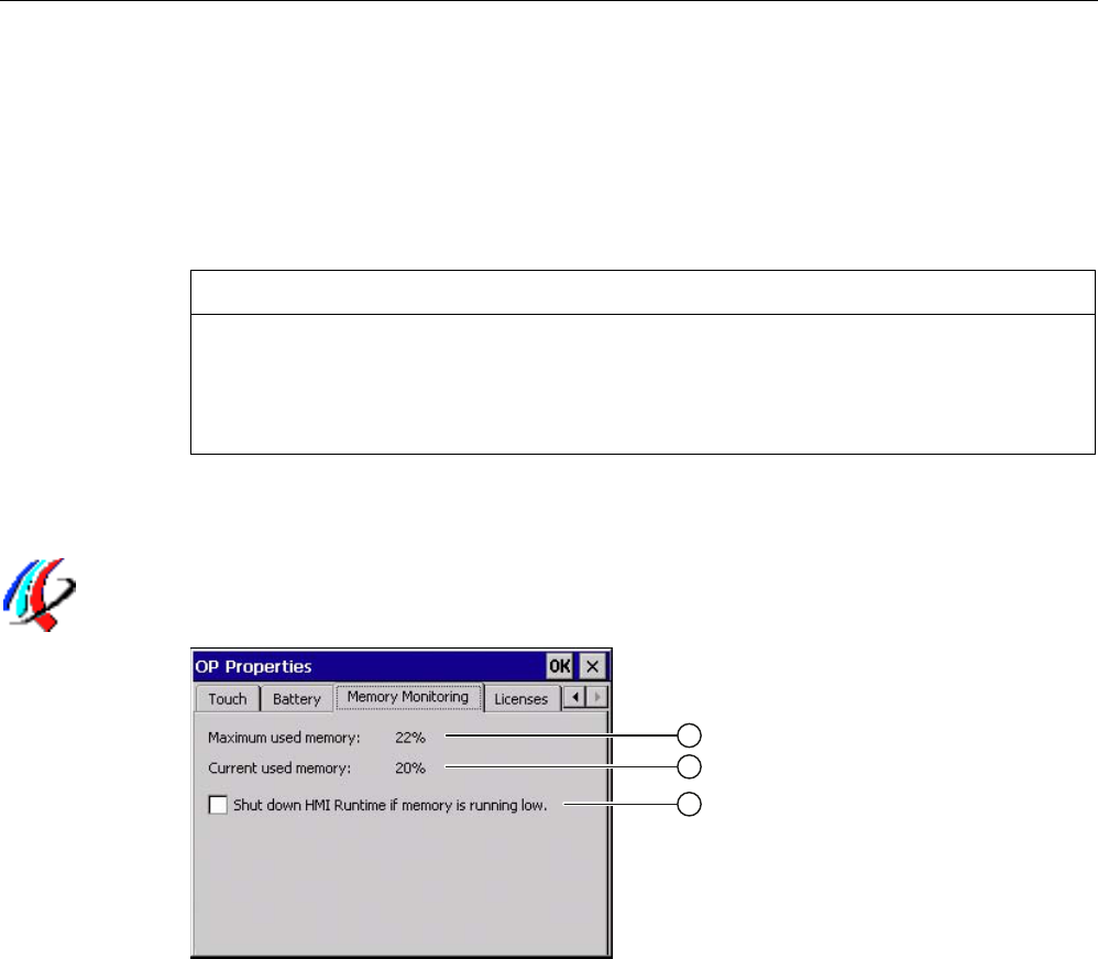
6.7.11 Activate memory management
If memory management is activated, the HMI device will automatically close the project if the
memory needs reorganizing during the active project.
If the project is closed due to this setting, then a message will be displayed on the HMI
device. You have to start the project again.
NOTICE
Memory management
If you do not activate memory management, malfunctions can occur during the runtime of
the project.
Select memory management in the "OP Properties" dialog.
Requirement
You have opened the "Memory Monitoring" tab in the "OP Properties" dialog using the
"OP" icon.
① Percent of maximum memory used since the last startup of the HMI device
② Percentage of memory currently used
③ Check box for selecting memory management
Procedure
Proceed as follows:
1. If you want to enable memory management, then select the check box.
2. Confirm your entries.
The dialog closes.
Result
Memory management is activated.
PRELIMINARY II
1.7.2010
Configuring the HMI device
6.7 Changing and displaying general settings
Wireless Teach Pendant F IWLAN V2
Operating Instructions, 08/2010, A5E02453837-01 137
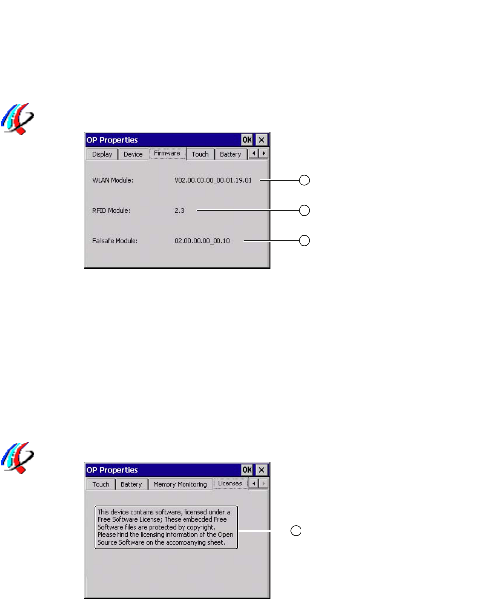
6.7.12 Display firmware
You can use this function to obtain information about the firmware used on the HMI device.
Requirement
You have opened the "Firmware" tab in the "OP Properties" dialog using the "OP" icon.
① Firmware for the WLAN module
② Firmware for the RFID module
③ Firmware for the fail-safe module
6.7.13 Displaying licensing information
You can use this function to obtain information about the licensing of the software used on
the HMI device.
Requirement
You have opened the "Licenses" tab in the "OP Properties" dialog using the "OP" icon.
① The HMI device contains software that has been licensed as free software. The embedded free
software files are protected by copyright. You can find the licensing information of the open
source software in the accompanying document.
PRELIMINARY II
1.7.2010
Configuring the HMI device
6.8 Enabling PROFINET IO
Wireless Teach Pendant F IWLAN V2
138 Operating Instructions, 08/2010, A5E02453837-01
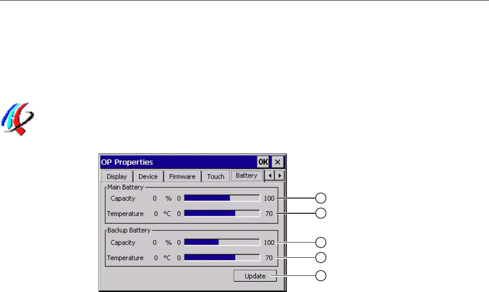
6.7.14 Displaying the charge status of the batteries
You can use this function to show the charge and temperature of the main rechargeable
battery and the buffer battery. The charge level is only shown if batteries are inserted or
connected.
Requirement ● The main rechargeable battery is installed.
● The bridge battery is connected.
● You have opened the "Battery" tab in the "OP Properties" dialog using the "OP" icon.
① Charge level of the main rechargeable battery
② Temperature of the main rechargeable battery
③ Charge level of the bridge battery
④ Temperature of the bridge battery
⑤ Button to update the display
Procedure If you want to refresh the display, press the "Update" button.
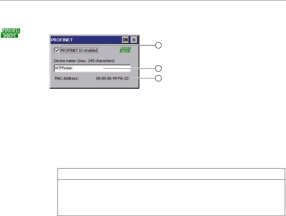
6.8 Enabling PROFINET IO
The HMI device communicates with the PLC via Ethernet. PROFINET IO must be enabled
so that you can use the following functions:
● Fail-safe operation with EMERGENCY STOP button and enabling button
● Use of PROFINET IO direct keys
PRELIMINARY II
1.7.2010
Configuring the HMI device
6.8 Enabling PROFINET IO
Wireless Teach Pendant F IWLAN V2
Operating Instructions, 08/2010, A5E02453837-01 139
Requirement You have opened the "PROFINET" dialog using the "PROFINET" icon.
① Enabling or disabling the PROFINET IO direct keys
② Text box for the device name
③ MAC address of the HMI device
Procedure Proceed as follows:
1. Select the "PROFINET IO enabled" check box.
2. Enter the device name of the HMI device.
NOTICE
Device name must match the HW Config
If the device name does not match the device name entered in the HW Config of
STEP 7, the project opens but there will be no PROFIsafe connection.
Use the device name from the HW Config of STEP 7.
The device name must be unique and satisfy the DNS conventions within the local network.
These include:
● Restriction to 127 characters in total (letters, digits, hyphen or point)
● A name component within the device name, e.g. a string between two points, may not
exceed 63 characters.
● Special characters such as umlauts, brackets, underscores, slashes, spaces etc. are not
permitted. The hyphen is the one exception.
● The device name must not start or end with the "-" character.
● The device name must not take the form n.n.n.n (n = 0 to 999).
● The device name must not start with the character string "port-xyz-" (x, y, z = 0 to 9).
1. Confirm your entries.
The dialog closes.
2. Restart the HMI device – see section "Starting the HMI device again (Page 113)".
Result PROFINET IO is enabled.
See also Direct keys (Page 219)
PRELIMINARY II
1.7.2010
Configuring the HMI device
6.9 Setting the PROFIsafe address
Wireless Teach Pendant F IWLAN V2
140 Operating Instructions, 08/2010, A5E02453837-01
6.9 Setting the PROFIsafe address
The PROFIsafe protocol is used to send safety message frames between the HMI device
and the F-CPU. This means each station in the PROFIsafe communication must be
assigned a unique PROFIsafe address.
At the start of the project, the HMI device is automatically integrated into the safety program.
The "SAFE" LED lights up to indicate that integration is complete.
You can enter the PROFIsafe address at the following locations:
● In the HMI device Control Panel
● In the WinCC flexible project
Loading the PROFIsafe address
NOTICE
Unique PROFIsafe address required
If a PROFIsafe address is not unique, you may experience malfunctions.
Assign a PROFIsafe address to the HMI device that is unique within the corresponding
local network segment.
Integration in PROFIsafe communication is not possible
The following PROFIsafe addresses must match to ensure that the HMI device can be
integrated in PROFIsafe communication:
The PROFIsafe address set in HW Config by STEP 7
The PROFIsafe address set in the "PROFIsafe" dialog
The PROFIsafe address that the HMI device loads depends on the configuration in the
Control Panel:
● A valid PROFIsafe address is entered in the Control Panel.
The HMI device then loads the registered PROFIsafe address. The PROFIsafe address
of a project is not loaded.
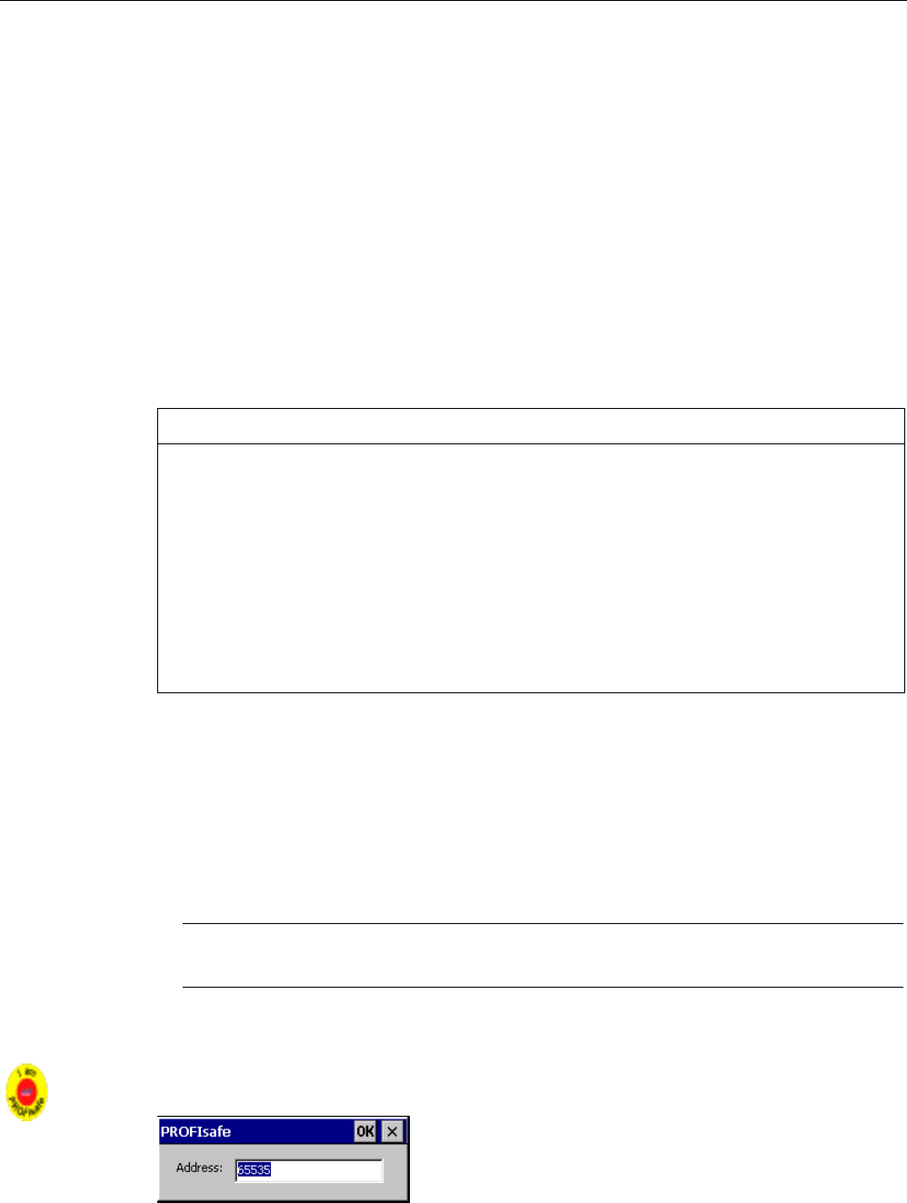
● The invalid PROFIsafe address "65535" is entered in the Control Panel.
The HMI device loads the PROFIsafe address set in the project.
Note
The default PROFIsafe address for the HMI device is 65535.
Requirement
You have opened the "PROFIsafe" dialog using the "PROFIsafe" icon.
PRELIMINARY II
1.7.2010
Configuring the HMI device
6.10 Reassigning an RFID tag ID
Wireless Teach Pendant F IWLAN V2
Operating Instructions, 08/2010, A5E02453837-01 141
Procedure
Proceed as follows:
1. If you want the HMI device to load the PROFIsafe address of the Control Panel, enter a
value from 1 to 65534 in the "Address:" text box.
2. If you want the HMI device to load the PROFIsafe address of the project, enter the value
65535 in the "Address:" text box.
The address obtained from the project will not be displayed in the dialog.
Result
The PROFIsafe address is set.
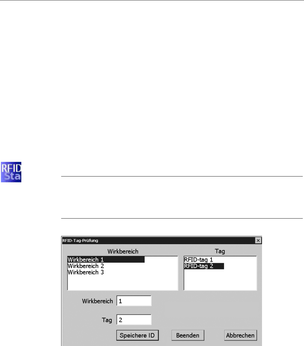
6.10 Reassigning an RFID tag ID
You can use this function to write existing IDs to one or more RFID tags, if you have
replaced one or more RFID tags.
Requirement
● The project, in which one or several RFID tags have failed, is located on the HMI device.
Note
If you have not transferred a project, the "Effective range" and "Tag" lists will be empty.
Similarly, if a project has been transferred without a configured effective range, the
"Effective range" and "Tag" lists will be empty and the following message will be
displayed:
● You have opened the "RFID Tag Test" dialog with the "RFID Config" icon.
Result
The configured effective ranges and the associated RFID tags are displayed in this dialog.
To write a new ID to one or more existing RFID tags, follow the procedure described in
section "Replacing an RFID tag (Page 202)".
PRELIMINARY II
1.7.2010
Configuring the HMI device
6.11 Programming the data channel
Wireless Teach Pendant F IWLAN V2
142 Operating Instructions, 08/2010, A5E02453837-01
6.11 Programming the data channel
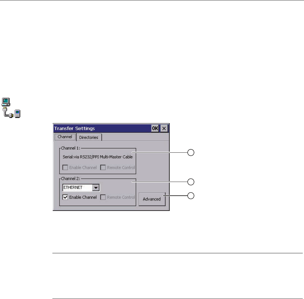
You can use this function to configure the transfer mode. A project can only be transferred
from the configuration PC to the HMI device when at least one data channel is configured
and enabled on the HMI device.
If you block all data channels, the HMI device is protected against unintentional overwriting
of the project data and HMI device image.
Requirement
The "Channel" tab in the "Transfer Settings" dialog has been opened with the
"Transfer Settings" icon.
① Group for data channel 1
The data channel 1 is not available with Wireless Teach Pendant F IWLAN.
② Group for data channel 2
③ Button for the "Network and Dial-Up Connections" dialog
Note
If you change the transfer settings during "Transfer", the new settings only go into effect the
next time the transfer function is started.
This may occur if the Control Panel is opened to change the transfer properties in an active
project.
Procedure
Proceed as follows:
1. Select the "Enable Channel" check box in the "Channel 2" group to enable the data
channel.
2. Select the interface for the data channel from the selection list.
PRELIMINARY II
1.7.2010

Configuring the HMI device
6.12 Configuring network operation
Wireless Teach Pendant F IWLAN V2
Operating Instructions, 08/2010, A5E02453837-01 143
3. Enter further parameters if required.
– Applies to "ETHERNET":
You can use the "Advanced" button to open the settings for addressing the HMI
device. You can find the required information in the section "Specifying the IP address
and name server (Page 146)".
– Applies to "USB"
No information is needed for "USB".
4. Confirm your entries.
The dialog closes.
Result
The data channel is configured.
6.12 Configuring network operation
6.12.1 Overview
You can use this function to configure the HMI device for data communication in a
PROFINET network via the Ethernet port.
Note
The HMI device can only be used in PROFINET networks.
The HMI device has client functionality in the local network. This means that users can
access files of a node with TCP/IP server functionality from the HMI device via the local
network. However, you cannot access data on the HMI device from a PC via the local
network, for example.
Information on communication using SIMATIC S7 via PROFINET is provided in the User
manual "WinCC flexible Communication Part 1"
(http://support.automation.siemens.com/WW/view/en/18797552).
The connection to a local network offers the following options, for example:
● Exporting or importing of recipe data records on or from a server
● Storing alarm and data logs
● Transferring a project
● Backing up data
PRELIMINARY II
1.7.2010

Configuring the HMI device
6.12 Configuring network operation
Wireless Teach Pendant F IWLAN V2
144 Operating Instructions, 08/2010, A5E02453837-01
Addressing computers
Computers are usually addressed using computer names within a PROFINET network.
These computer names are translated from a DNS or WINS server to TCP/IP addresses.
This is why a DNS or WINS server is needed for addressing via computer names when the
HMI device is in a PROFINET network.
The corresponding servers are generally available in PROFINET networks.
Note
The use of TCP/IP addresses to address PCs is not supported by the operating system.
Contact your network administrator for more information.
Determine the following parameters:
● Does the local network use DHCP for dynamic assignment of addresses?
If not, get a TCP/IP address for the HMI device.
● Which TCP/IP address does the default gateway have?
● If a DNS network is used, what is the address of the name server?
● If a WINS network is used, what is the address of the name server?
Configuration includes:
● Specifying the computer name of the HMI device
● Specifying the IP address and name server
● Specifying the logon data
● Configuring e-mail
The configuration work is described in the following sections.
PRELIMINARY II
1.7.2010
Configuring the HMI device
6.12 Configuring network operation
Wireless Teach Pendant F IWLAN V2
Operating Instructions, 08/2010, A5E02453837-01 145
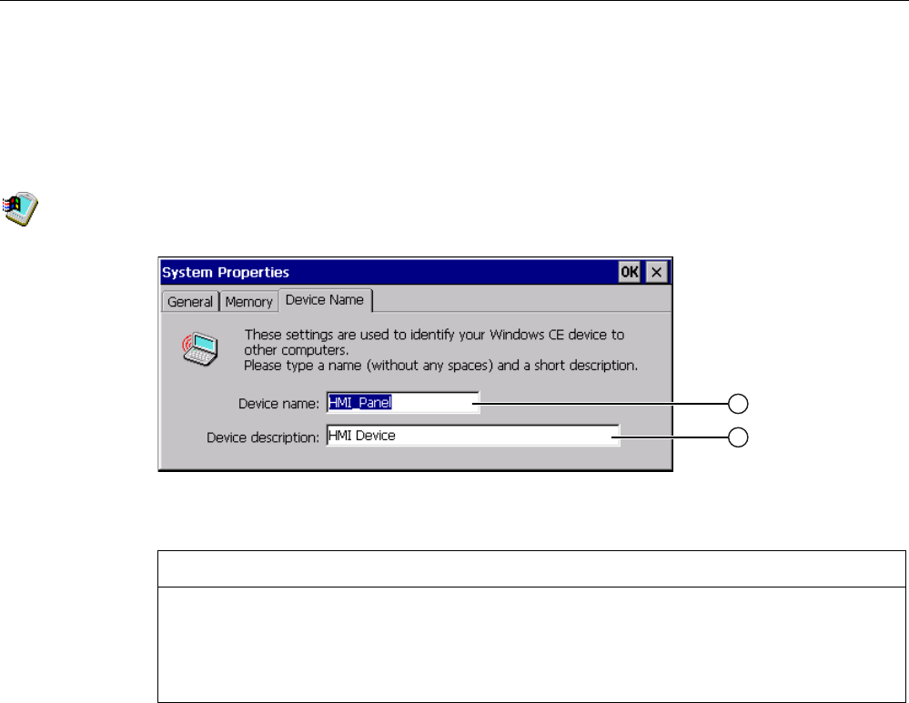
6.12.2 Specifying the computer name of the HMI device
You can use this function to assign a computer name to the HMI device. The computer name
is used to identify the HMI device in the local network.
Requirement You have opened the "Device Name" tab in the "System Properties" dialog box using the
"System" icon.
① Computer name of the HMI device
② Description for the HMI device (optional)
NOTICE
Computer name must be unique
Communication errors may occur in the local network if you assign a computer name more
than once.
Enter a unique computer name in the ""Device name"" text box.
Procedure
Proceed as follows:
1. Enter the computer name for the HMI device in the "Device name" text box.
Enter the name without spaces.
2. If necessary, enter a description for the HMI device in the "Device description" text box.
3. Confirm your entries.
The dialog closes.
Result
The computer name for the HMI device is now set.
PRELIMINARY II
1.7.2010
Configuring the HMI device
6.12 Configuring network operation
Wireless Teach Pendant F IWLAN V2
146 Operating Instructions, 08/2010, A5E02453837-01
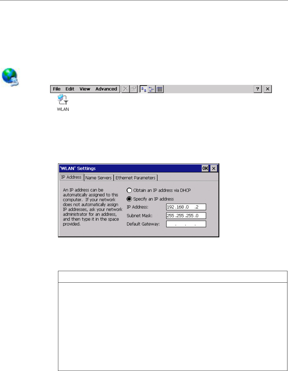
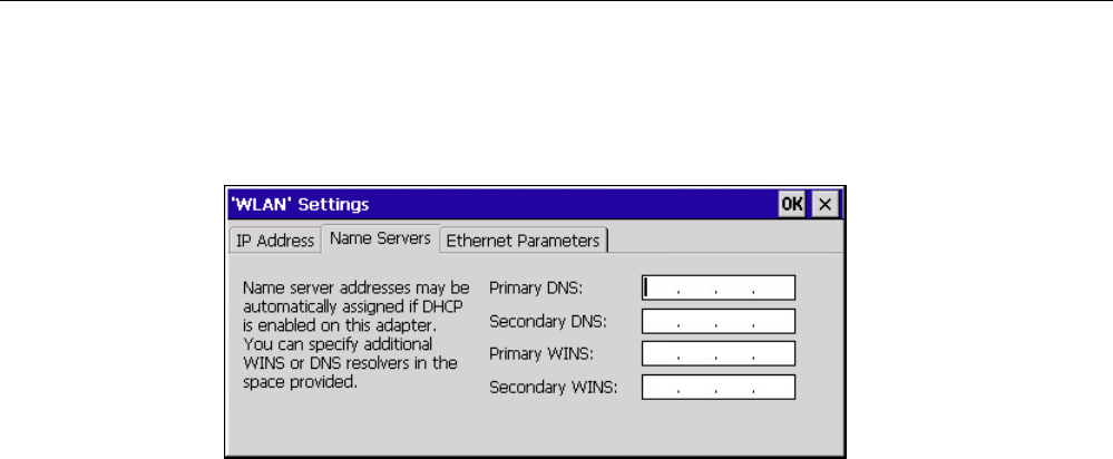
6.12.3 Specifying the IP address and name server
You can use this function to make the settings for addressing the HMI device in the local
network. Ask your network administrator for the required information.
Requirement
You have opened the following display using the "Network&Dial-Up Connections" icon.
Procedure
Proceed as follows:
1. Press the "WLAN" icon.
The 'WLAN' Settings dialog is displayed.
2. If you need automatic address assignment, select the "Obtain an IP address via DHCP"
radio button.
3. If you need manual address assignment, select the "Specify an IP address" radio button.
NOTICE
IP address must be unique
An address conflict will occur if more than one device is assigned the same IP address
in the local network.
Assign a unique IP address to each HMI device in the local network.
Reserved IP addresses
The following IP addresses are reserved for internal communication with the WLAN
module:
169.254.2.253
169.254.2.254
Do not use these reserved IP addresses.
PRELIMINARY II
1.7.2010
Configuring the HMI device
6.12 Configuring network operation
Wireless Teach Pendant F IWLAN V2
Operating Instructions, 08/2010, A5E02453837-01 147
4. If you have selected manual address assignment, enter the corresponding addresses in
the "IP Address," "Subnet Mask" text boxes and if necessary in "Default Gateway."
5. If a name server is used in the local network, open the "Name Servers" tab.
6. Enter the respective addresses in the text boxes.
7. Confirm your entries.
The dialog closes.
8. If you want to change the Ethernet parameters, open the "Ethernet Parameters" tab.
9. Close the "Network&Dial-Up Connections" display.
The Control Panel is displayed again.
Result The address parameters of the HMI device have been set.
PRELIMINARY II
1.7.2010
Configuring the HMI device
6.12 Configuring network operation
Wireless Teach Pendant F IWLAN V2
148 Operating Instructions, 08/2010, A5E02453837-01
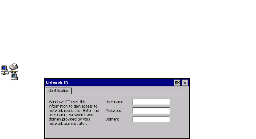
6.12.4 Specifying the logon data
Use this function to enter the information for logging on to the local network.
Ask your network administrator for the required information.
Requirement
You have opened the "Network ID" dialog box using the "Network ID" icon.
Procedure
Proceed as follows:
1. Enter your user name in the "User name" text box.
2. Enter your password in the "Password" text box.
3. In the "Domain"input field, enter the name of your assigned domain.
4. Confirm your entries.
The dialog closes.
Result
The logon data has now been set.
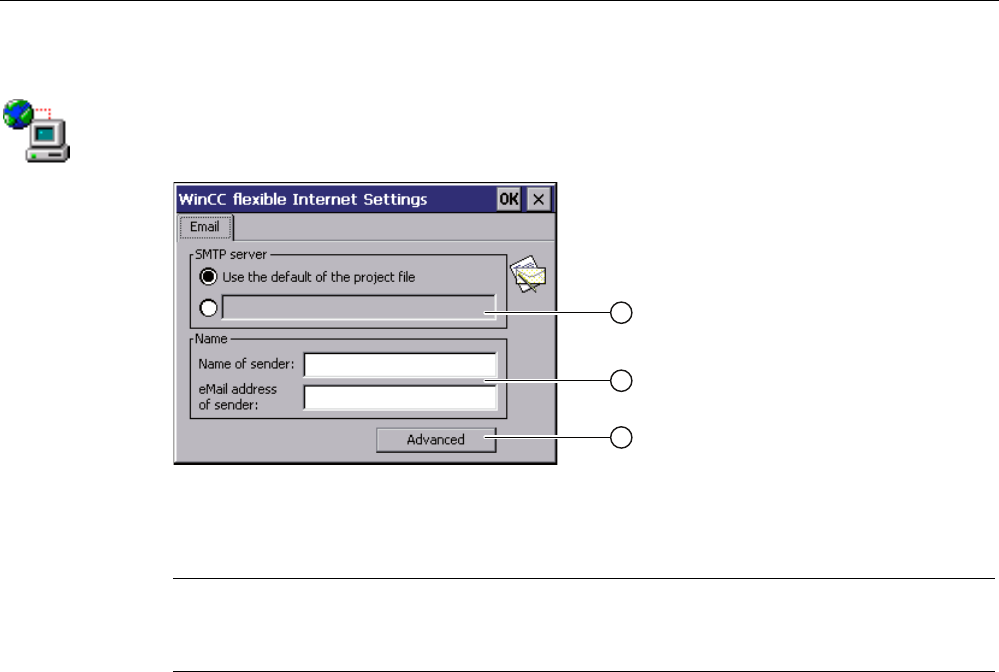
6.12.5 Configuring e-mail
You can use this function to set the SMTP server, sender name and e-mail account for e-
mail service. Ask your network administrator for the required information.
PRELIMINARY II
1.7.2010
Configuring the HMI device
6.12 Configuring network operation
Wireless Teach Pendant F IWLAN V2
Operating Instructions, 08/2010, A5E02453837-01 149
Requirement
You have opened the "Email" tab in the "WinCC flexible Internet Settings" dialog using the
"WinCC Internet Settings" icon.
① Setting the SMTP server
② Name of the sender and e-mail account
③ "Advanced" button for advanced settings
Note
Additional tabs may appear in the "WinCC flexible Internet Settings" dialog. This depends on
the options that have been enabled for operating the local network in the project.
Procedure
Proceed as follows:
1. Specify the SMTP server.
– Select the "Use the default of the project file" option if you want to use the SMTP
server configured in the project.
– Clear the "Use the default of the project file" option if you do not want to use the SMTP
server configured in the project. Specify the required SMTP server.
2. Enter the name for the sender in the "Name of sender" text box.
The computer name is practical as the sender name – see section "Specifying the
computer name of the HMI device (Page 145)".
3. Enter the e-mail account for your e-mail in the "eMail address of sender" text box.
Some e-mail providers will only let you send e-mails if you specify the e-mail account.
The "eMail address of sender" text box can remain empty if your e-mail provider lets you
send e-mails without checking the account.
PRELIMINARY II
1.7.2010
Configuring the HMI device
6.12 Configuring network operation
Wireless Teach Pendant F IWLAN V2
150 Operating Instructions, 08/2010, A5E02453837-01
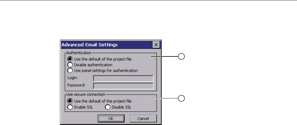
4. Use the "Advanced" button to open advanced settings for the sending of e-mails via an
SMTP server.
① Options for authentication on the SMTP server
② Encryption options
Specify an option for authentication on the SMTP server.
– Select the "Use the default of the project file" option if you want to use authentication
data specified in the project.
– If you use an SMTP server that does not require authentication, select the
"Disable authentification" option.
– Select the "Use panel settings for authentification" option if you want to use the
authentication data specified in the settings of the HMI device instead of those in the
project.
Specify the encryption method.
– Select the "Use the default of the project file" option if you want to use the encryption
method specified in the project.
– Select the "Enable SSL" option if you want to use SSL encryption.
– Select the "Disable SSL" option if you do not want to use encryption.
5. Apply the advanced settings with the "OK" button.
6. Confirm your entries.
The dialog closes.
Result
The e-mail settings have been changed.
PRELIMINARY II
1.7.2010
Configuring the HMI device
6.13 Changing Internet settings
Wireless Teach Pendant F IWLAN V2
Operating Instructions, 08/2010, A5E02453837-01 151
6.13 Changing Internet settings
6.13.1 Changing general settings
You can use this function to set the homepage and search engine page for an Internet
connection via the Internet Explorer. Ask your network administrator for the required
information.
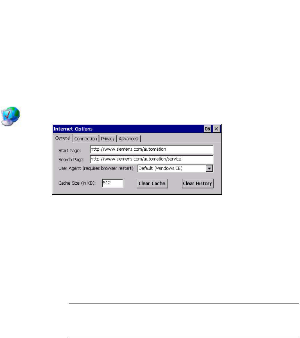
Requirement You have opened the "General" tab in the "Internet Options" dialog box using the
"Internet Options" icon.
Procedure Proceed as follows:
1. Enter the homepage for the Internet browser in the "Start Page" text box.
2. Enter the address of the default search engine in the "Search Page" text box.
3. Enter the display format of the Internet pages in the "User Agent" text box.
The following display formats can be selected:
– Default (Windows CE)
– Same as Pocket PC
– Same as Windows XP
Note
The "Default (Windows CE)" display format is optimized for Internet pages on a HMI
device with the Windows CE operating system. "Default (Windows CE)" is therefore
the most suitable.
4. Enter the required amount of cache in the "Cache" text box.
5. If you want to delete the cache, press the "Clear Cache" button.
6. If you want to delete the history, press the "Clear History" button.
7. Confirm your entries.
The dialog closes.
PRELIMINARY II
1.7.2010
Configuring the HMI device
6.13 Changing Internet settings
Wireless Teach Pendant F IWLAN V2
152 Operating Instructions, 08/2010, A5E02453837-01
Result
The general parameters for the Internet browser have been set. The settings take effect the
next time you start the Internet Explorer.
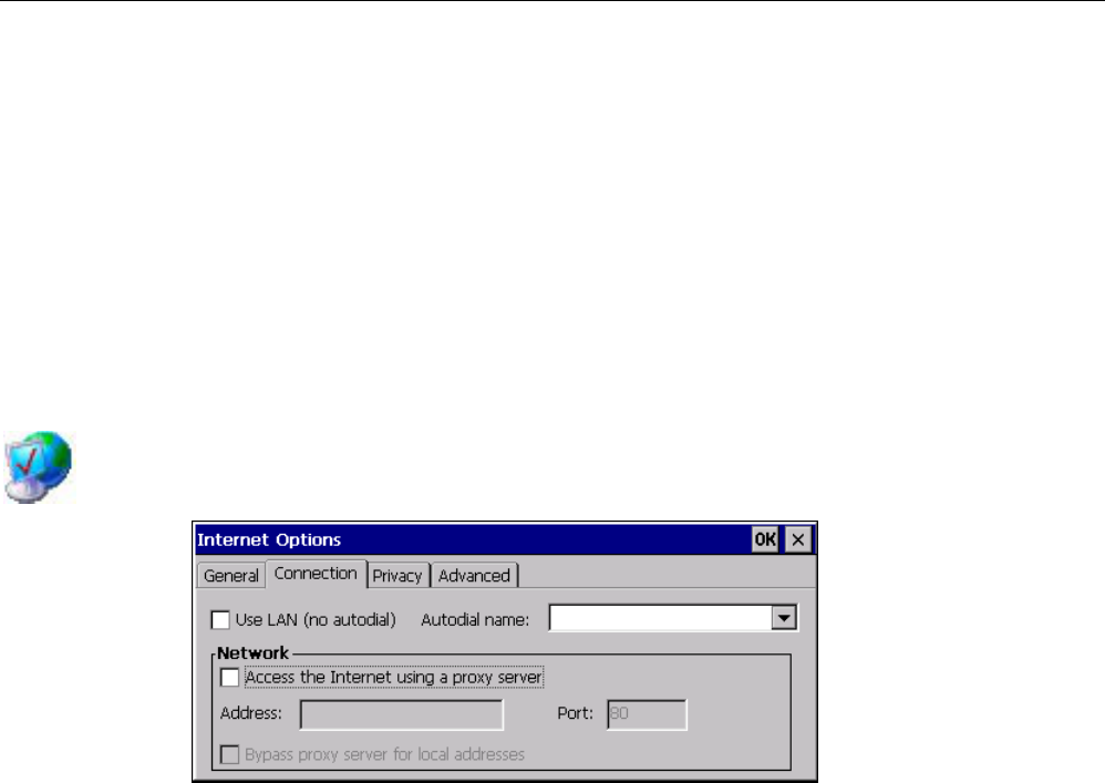
6.13.2 Setting the proxy server
Use this function to configure the type of Internet access. Ask your network administrator for
the required information.
Requirement
You have opened the "Connection" tab in the "Internet Options" dialog box using the
"Internet Options" icon.
Procedure
Proceed as follows:
1. Select the "Use LAN (no autodial)" check box.
2. If you are using a proxy server, in the "Network" group, select the
"Access the Internet using a proxy server" check box.
Specify the address and port of the proxy server.
3. If you want to bypass the proxy server for local addresses, select the
"Bypass proxy server for local addresses" check box.
4. Confirm your entries.
The dialog closes.
Result
The parameters for the LAN connection have been made.
PRELIMINARY II
1.7.2010
Configuring the HMI device
6.13 Changing Internet settings
Wireless Teach Pendant F IWLAN V2
Operating Instructions, 08/2010, A5E02453837-01 153
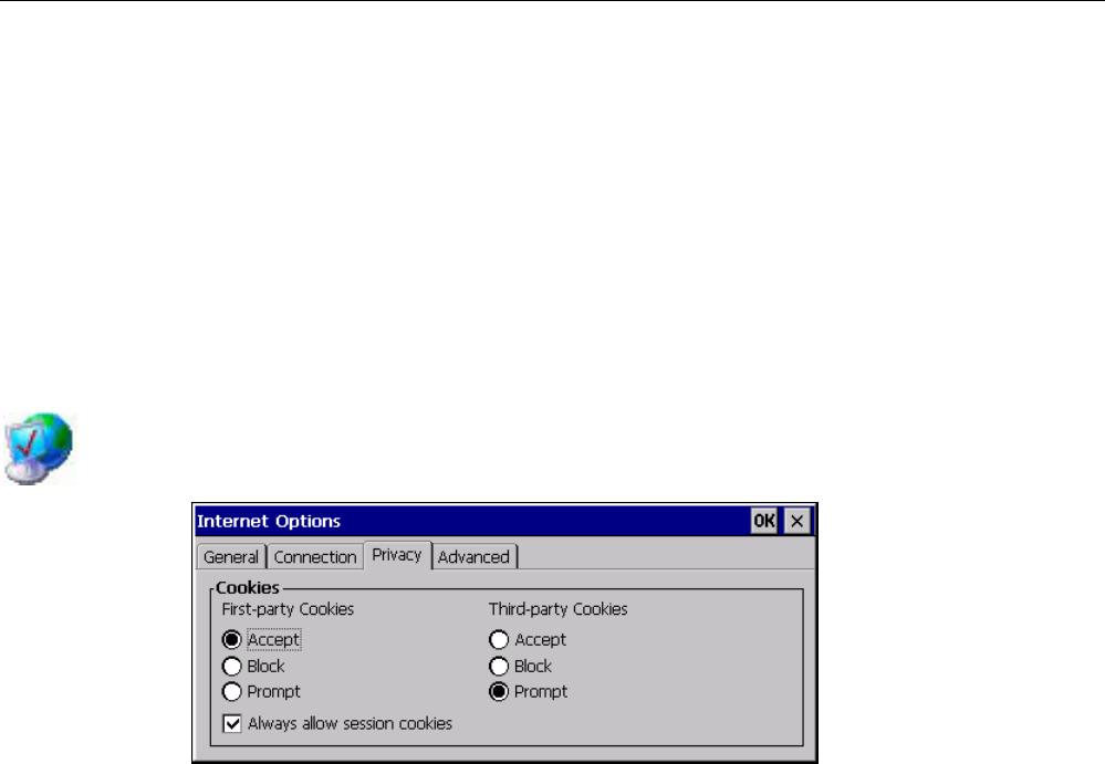
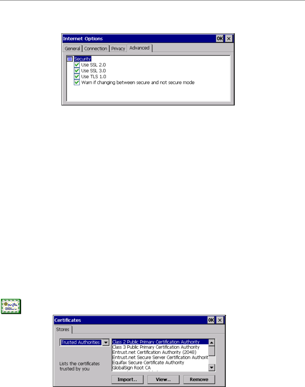
6.13.3 Changing Internet security settings
Cookies contain information sent by a Web server to a browser. The cookie is sent back
when the Web server is accessed at a later time. This step involves sending stored
information for subsequent access.
Data can be sent encrypted for greater data security on the Internet. Common encryption
protocols include SSL and TLS. You can activate or deactivate the usage of encryption
protocols.
Ask your network administrator for the required information.
Requirement
You have opened the "Privacy" tab in the "Internet Options" dialog box using the
"Internet Options" icon.
Procedure
Proceed as follows:
1. Select the required cookie behavior by means of the radio buttons.
– "Accept"
Cookies are stored without request.
– "Block"
Cookies will not be stored.
– "Prompt"
Cookies will be stored on request.
2. If you want allow cookies which are restricted to a single session, select the
"Always allow session cookies" check box.
PRELIMINARY II
1.7.2010
Configuring the HMI device
6.13 Changing Internet settings
Wireless Teach Pendant F IWLAN V2
154 Operating Instructions, 08/2010, A5E02453837-01
3. Change to the "Advanced" tab.
4. Activate the required encryption protocol.
5. Confirm your entries.
The dialog closes.
Result
The accepted cookies and the required encryption protocol are set.
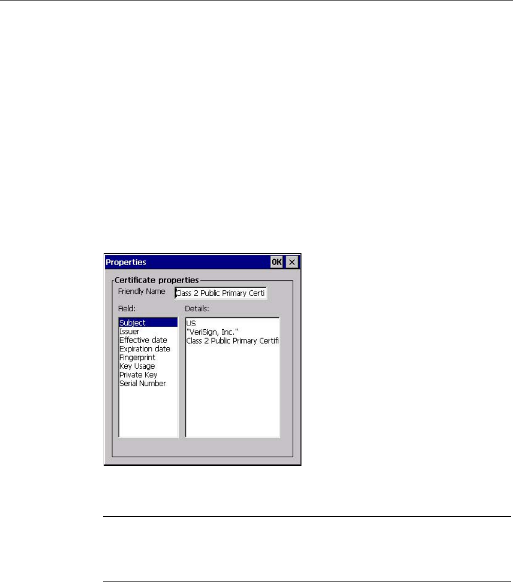
6.13.4 Importing, displaying and deleting certificates
You can use this function to import, display and delete certificates. The certificates differ as
follows:
● Certificates that you trust
● Own certificates
● Other certificates
A digital certificate consists of structured data, which confirms ownership and other
properties of a public key. Ask your network administrator about the certificates required for
your application.
Requirement
You have opened the "Certificates" dialog box with the "Certificates" icon.
PRELIMINARY II
1.7.2010
Configuring the HMI device
6.13 Changing Internet settings
Wireless Teach Pendant F IWLAN V2
Operating Instructions, 08/2010, A5E02453837-01 155
Procedure
Proceed as follows:
1. Select the type of certificate from the selection box:
– "Trusted Authorities" for reliable certificates
– "My Certificates" for your own certificates
– "Other Certificates" for other certificates
2. If you want to import a certificate, press the "Import" button.
A dialog with information about the source opens.
– Select the required source.
– Close the dialog.
3. If you want to display the properties of the selected certificate, press the "View" button.
The following dialog appears:
4. If you want to delete a certificate, first select it.
5. Confirm by pressing the "Remove" button in the "Certificates" dialog.
Note
The entry is deleted immediately and without further inquiry.
If you want to again use a deleted certificate, you need to import it again from a storage
medium.
6. Confirm your entries.
The dialog closes.
Result
The number of saved certificates has changed.
PRELIMINARY II
1.7.2010
Configuring the HMI device
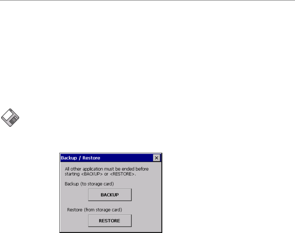
6.14 Saving to external storage medium – backup
Wireless Teach Pendant F IWLAN V2
156 Operating Instructions, 08/2010, A5E02453837-01
6.14 Saving to external storage medium – backup
You can use this function to back up the operating system, applications and data from the
internal in flash memory of the HMI device to an external storage medium. See section
"Displaying information about the HMI device (Page 135)".
The following external storage media can be used:
● Memory card
● USB memory stick
Requirement
● Storage medium with sufficient free capacity is inserted in the memory card slot.
See section "Accessories (Page 16)".
● Data that might be overwritten are saved.
● You have opened the "Backup/Restore" dialog box using the "Backup/Restore" icon.
Procedure
Proceed as follows:
1. Click the "BACKUP" button.
The "Select Storage Card"" dialog box is displayed. The "--- no storage card available ---"
message appears if there is no memory card in the HMI device or it is defective. Insert a
memory card or insert another one.
2. Select the storage medium for backup from the "Please select a Storage Card" list box.
3. Click the "Start Backup" button.
The HMI device checks the storage medium.
If the "This storage card..." message appears, you need a storage medium of greater
capacity. Acknowledge this message. Backup is aborted at this point. Insert a storage
medium with a greater capacity and restart the backup process.
If the "You may have an old backup on the storage card. Do you want to delete it?"
message appears, there is already a backup on the storage medium.
PRELIMINARY II
1.7.2010
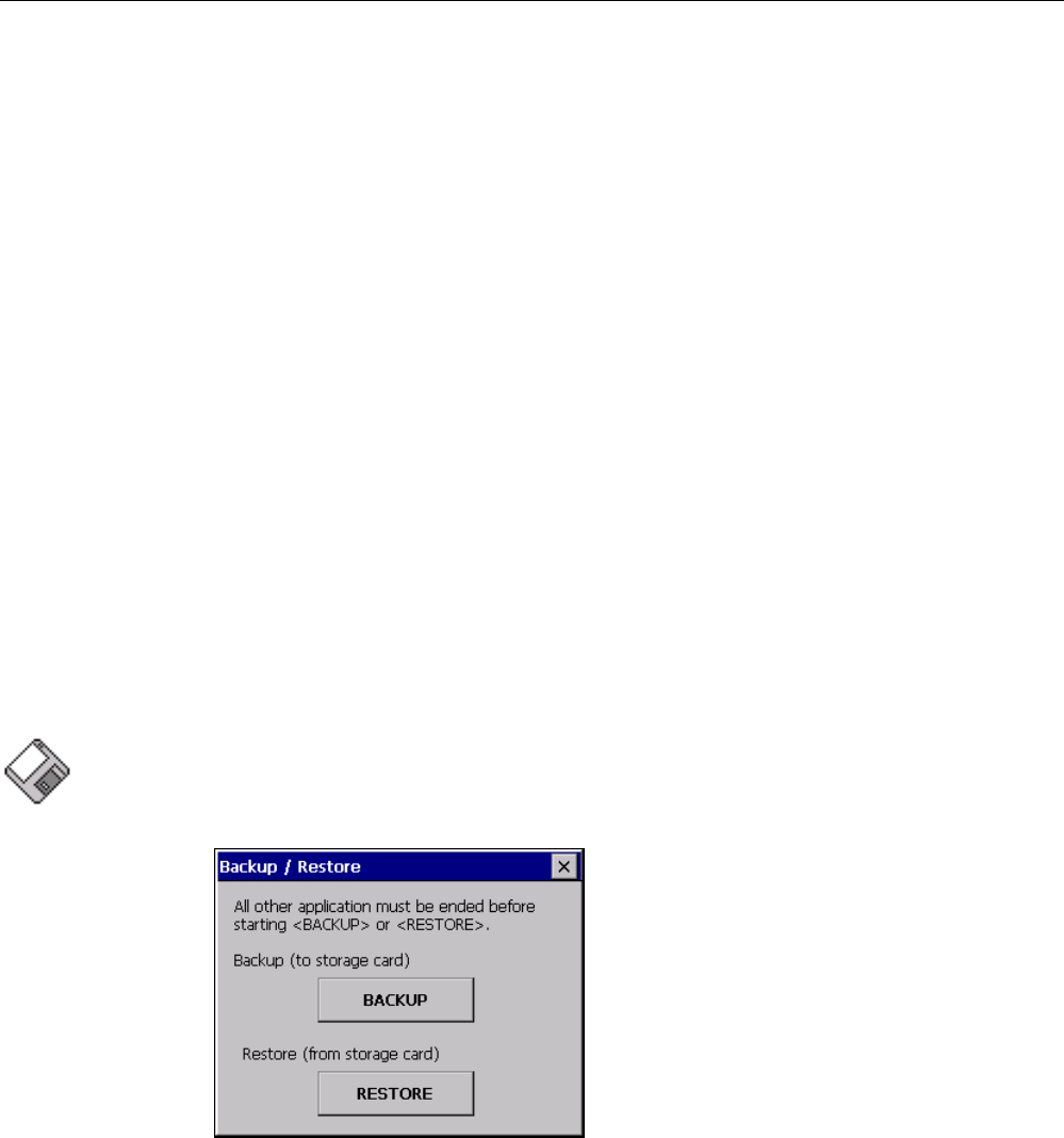
Configuring the HMI device
6.15 Restoring from external storage medium – Restore
Wireless Teach Pendant F IWLAN V2
Operating Instructions, 08/2010, A5E02453837-01 157
If you do not want to overwrite the backup, press the ""No"" button. Otherwise, click the
"Yes" button.
Several messages are displayed in sequence during the backup process:
– Saving registry data
– Copy files
A progress bar shows the status of the backup process. When the backup process is
completed, the "The operation completed successfully." message is displayed.
4. Acknowledge this message.
The dialog closes.
Result The HMI device data is now saved on the storage medium.
6.15 Restoring from external storage medium – Restore
Use this function to restore data from a storage medium to the HMI device.
A restore operation deletes the old data from flash memory of the HMI device on
confirmation. The data stored on the storage medium is then copied to the internal flash
memory.
Requirement ● The storage medium with the backup data is inserted in the HMI device.
See section "Accessories (Page 16)".
● You have opened the "Backup/Restore" dialog box using the "Backup/Restore" icon.
PRELIMINARY II
1.7.2010
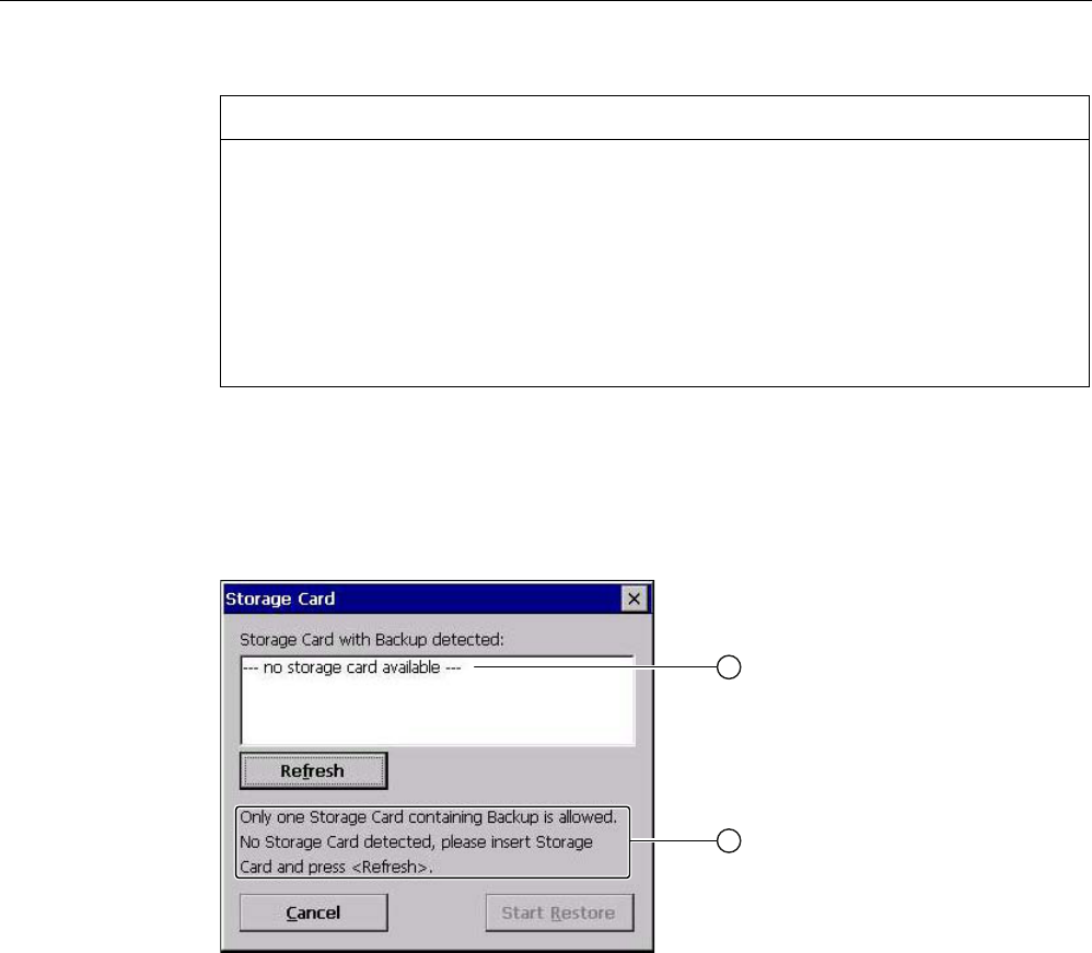
Configuring the HMI device
6.15 Restoring from external storage medium – Restore
Wireless Teach Pendant F IWLAN V2
158 Operating Instructions, 08/2010, A5E02453837-01
NOTICE
Data loss
All data on the HMI device will be deleted during a restore operation. License keys will
be deleted after query.
Back up the HMI device's data before restoring if required.
Memory card with data backup
If several storage media with data backups are inserted, the data cannot be restored.
Remove the storage medium with the data backups you do not need.
Procedure Proceed as follows:
1. Click the "RESTORE" button.
The "Storage Card" dialog box opens.
① No memory card available
② Only one memory card with a backup is permitted. No memory card detected. Insert a
memory card and press the "Refresh" button.
2. Select the storage medium with the backup from the "Storage Card with Backup
detected" selection box.
The "--- no storage card available ---" message appears if there is no storage medium in
the HMI device or it is defective.
3. If the "--- no storage card available ---" message appears, press the "Cancel" button.
Restoring is then aborted.
– Insert a storage medium or another one.
– Click the "Refresh" button.
The content of the selection box changes.
– Select the storage medium with the backup from the "Storage Card with Backup
detected" selection box.
PRELIMINARY II
1.7.2010

Configuring the HMI device
6.15 Restoring from external storage medium – Restore
Wireless Teach Pendant F IWLAN V2
Operating Instructions, 08/2010, A5E02453837-01 159
4. Click the "Start Restore" button.
Restoring is started.
5. The data to be restored is checked.
The following messages are displayed in sequence during the check.
– "Starting Restore"
– "Checking data"
When the data has been checked, the following message is displayed:
"You are starting RESTORE now. All files (except files on storage cards) and the registry
will be erased. Are you sure?"
6. If you do not want to permit that data are deleted from the HMI device, abort the restore
process by pressing the "ESC" button.
7. Start to restore the data by selecting "Yes".
The following messages are displayed in sequence during the restore:
– "Deleting files on flash"
– "Restore CE Image"
A progress bar shows the status of the restore process.
When restore is completed, the following message is displayed:
"Restore succesfully finished. Press ok, remove your storage card and reboot your
device."
8. Remove the storage medium.
9. Acknowledge this message.
The HMI device starts again.
Result
The data from the storage medium is now on the HMI device.
Note
After the restore, check whether it is necessary to calibrate the touch screen.
PRELIMINARY II
1.7.2010

Configuring the HMI device
6.15 Restoring from external storage medium – Restore
Wireless Teach Pendant F IWLAN V2
160 Operating Instructions, 08/2010, A5E02453837-01
PRELIMINARY II
1.7.2010

Wireless Teach Pendant F IWLAN V2
Operating Instructions, 08/2010, A5E02453837-01 161
Safety-related configuration 7
7.1 General procedure
Programs for fail-safe operation
For fail-safe operation of the HMI device, the following software is required:
● STEP 7, V5.4, as of SP2, "HW Config" hardware configuration
● Add-on package "S7 Distributed Safety", V5.4, SP3
● WinCC flexible
See also section "Software requirements (Page 22)".
The programs are launched on the configuration computer by the SIMATIC Manager. You
can find additional information in the Start menu.
Program Task Start menu
STEP 7, HW Config Creating a project for the
automation system
SIMATIC >
Documentation >
desired language
S7 Distributed Safety Create a safety program SIMATIC >
Documentation >
desired language
WinCC flexible Create a project for the HMI
device
SIMATIC >
WinCC flexible 2008 >
WinCC flexible help system
Procedure
Proceed as follows:
1. Create a STEP 7 project in the SIMATIC Manager.
2. Configure the desired F-CPU and a PROFINET connection in the hardware configuration
"HW Config".
3. Add a mobile HMI device to the configuration from the hardware catalog of HW Config.
4. Set the parameters for the communication with the controller.
See section "Assigning parameters for communication between the HMI device and the
controller (Page 163)".
5. Configure other components in accordance with your plant.
6. Create a safety program for the F-CPU in STEP 7 with S7 Distributed Safety.
PRELIMINARY II
1.7.2010

Safety-related configuration
7.2 Checklist for configuration
Wireless Teach Pendant F IWLAN V2
162 Operating Instructions, 08/2010, A5E02453837-01
7. Insert the F-FBs required for the HMI device in the safety program.
Wire these FBs according to the instructions. Follow the checklist for this procedure – see
section "Checklist for EMERGENCY STOP configuration (Page 167)".
8. Open the program, WinCC flexible ES.
9. Create a project for the HMI device.
10. Set "Ethernet/Wireless" in the project view under "Communication".
11. Configure the PROFIsafe address of the HMI device in the project window under "Device
Settings > Device Settings".
12. Configure the effective ranges for your plant under "Device Settings > Effective Ranges".
13. Configure the HMI screens for operator control and monitoring of the plant in fail-safe
mode.
7.2 Checklist for configuration
Perform the following tasks for safety-related configuration. Confirm each task by checking it
off in the following list.
Task Information source Check
STEP 7, HW Config
Add the HMI device to the plant configuration
Set the PROFIsafe parameters
SIMATIC STEP 7 (Page 163)
S7 Distributed Safety
Call the required F-FBs in the safety program
Programming and operation manual
"S7 Distributed Safety - Configuring
and Programming"
(http://support.automation.siemens.co
m/WW/view/en/22099875)
WinCC flexible
Configure the unique project identifiers for the
effective ranges and operator controls
Configuration in WinCC flexible
(Page 179)
Configuring the HMI device Configuring the HMI device (Page 97)
PRELIMINARY II
1.7.2010

Safety-related configuration
7.3 SIMATIC STEP 7
Wireless Teach Pendant F IWLAN V2
Operating Instructions, 08/2010, A5E02453837-01 163
7.3 SIMATIC STEP 7
7.3.1 Configuring in STEP 7
Requirement
● A STEP 7 project has been created in SIMATIC Manager.
Procedure
Proceed as follows:
1. Configure the required F-CPU and a PROFINET connection in the hardware
configuration "HW Config".
2. Add a mobile HMI device to the configuration from the hardware catalog of HW Config.
To do this, drag the HMI device onto the PROFINET connection in the station window.
3. Open the object properties of the HMI device in the shortcut menu and set the
parameters for the communication to the controller.
If the HMI device is not listed in the hardware catalog of HW Config, you need to integrate
the official GSD file (device database) for the HMI device in the STEP 7 database.
You can find the GSDML file on the data medium included in the scope of delivery or by
contacting your Siemens representative in the Internet
(http://www.automation.siemens.com/mcms/aspa-db/en/Pages/default.aspx).
Note
The supplied GSD files have integrated themselves into STEP 7 during installation of
WinCC flexible.
7.3.2 Assigning parameters for communication between the HMI device and the
controller
If you select the HMI device in the HW Config, the following modules are displayed:
● WTPfiwlanv2
● WTPStandard-IO
● WTPFailsafe_IO
You can find information on configuring the F I/O in STEP 7 in the following manuals:
● Programming and operation manual "S7 Distributed Safety - Configuring and
Programming" (http://support.automation.siemens.com/WW/view/en/22099875)
● "Safety Technology in SIMATIC S7" system manual
(http://support.automation.siemens.com/WW/view/en/12490443)
PRELIMINARY II
1.7.2010

Safety-related configuration
7.3 SIMATIC STEP 7
Wireless Teach Pendant F IWLAN V2
164 Operating Instructions, 08/2010, A5E02453837-01
You can find information on working in HW Config in "Configuring Hardware and
Connections with STEP 7" manual
(http://support.automation.siemens.com/WW/view/en/18652631) as well as in the online help
for HW Config.
Configure the parameters for fail-safe mode in the object properties of the WTPFailsafe_IO
module. A password is required for the safety program. You can find additional information
on access protection in Programming and operation manual "S7 Distributed Safety -
Configuring and Programming"
(http://support.automation.siemens.com/WW/view/en/22099875).
Procedure
NOTICE
Maximum response time
If an error occurs, the monitoring time will be included in the maximum response time.
Select a monitoring time short enough to ensure that the error tolerance time of the
production process will not be exceeded.
Proceed as follows:
1. Set the address area for the process image in the "Addresses" tab.
The process image is a memory area in the controller which the HMI device and
controller access together. At the beginning of the cyclic control program the signal states
of the inputs of the HMI device are transferred to the controller via the process input
images, PII. At the end of the cyclic program the process image of the outputs, PIQ is
transferred as a signal state to the HMI device.
Parameter Meaning
Input > Address > Start of
Address Area
Start address of the inputs in the process image. The safety-
relevant user data of the HMI device is shown.
The allocation depends on the controller used.
Input > process image Process image to which the address range of the inputs
belongs, PII.
This parameter cannot be changed for SIMATIC CPU 300 type
controllers.
Output > Address > Start of
Address Area
Start address of the outputs in the process image The safety-
relevant user data of the HMI device is shown.
The allocation depends on the controller used.
Output > process image Process image to which the address range of the outputs
belongs, PIQ.
This parameter cannot be changed for SIMATIC CPU 300 type
controllers.
PRELIMINARY II
1.7.2010

Safety-related configuration
7.3 SIMATIC STEP 7
Wireless Teach Pendant F IWLAN V2
Operating Instructions, 08/2010, A5E02453837-01 165
2. In the "PROFIsafe" tab, set the "F_Dest_Add" and "F_WD_Time" parameters.
Parameter Meaning
F_Dest_Add PROFIsafe address used to uniquely identify the destination
throughout the network and station.
The address is assigned automatically. The "F_Dest_Add"
parameter can have a value between 1 and 65534.
F_WD_Time (ms) Monitoring time in the fail-safe IO device.
A valid current safety frame must reach the F-CPU and be
returned to the HMI device within the monitoring time period.
This ensures that failures and errors are detected and
appropriate responses are triggered to keep the fail-safe
system in a safe state or transfer it to a safe state.
You should select a monitoring time long enough for message
frame delays to be tolerated by the communication system, but
short enough for the fault reaction function to respond quickly
enough in the event of a fault (for example interruption of the
communication connection).
You can set the "F_WD_Time" parameter in 1 ms increments.
The monitoring period is set at 500 ms. Calculate the minimum
monitoring time using Excel table "s7fcotia.xls"
(http://support.automation.siemens.com/WW/view/en/21627074
).
This table is part of the option package S7 Distributed Safety.
You can find the parameters needed to calculate the monitoring
time under "General specifications".
The following parameters are fixed:
Parameter Meaning
F_SIL Safety class of the HMI device
The value of the parameter is set to "SIL 3".
F_Block_ID This parameter must be set to the value "0", because there is
no checksum of the individual device parameters.
F_Par_Version Implemented PROFIsafe version.
The value of the parameter is set to "1". This means
PROFIsafe V2 will be used.
F_Source_Add PROFIsafe address used to uniquely identify the source
throughout the network and station.
The address is assigned automatically. The "F_Source_Add"
parameter can have a value between 1 and 65534.
PRELIMINARY II
1.7.2010

Safety-related configuration
7.3 SIMATIC STEP 7
Wireless Teach Pendant F IWLAN V2
166 Operating Instructions, 08/2010, A5E02453837-01
7.3.3 "SIMATIC S7 Distributed Safety" add-on
During fail-safe operation, a safety program runs in the F-CPU. The HMI device is integrated
into this safety program.
The HMI device and F-CPU communicate via PROFINET IO. PROFIsafe as of V2.0 is
required for safety-related communication.
The HMI device has the following safety features:
● Detects the signal states of the EMERGENCY STOP button and enabling button
● Sends the signal states to the F-CPU in the form of safety message frames
Safety program and fail-safe blocks
For fail-safe operation of the HMI device, you need to configure a safety program in STEP 7
with the "SIMATIC S7 Distributed Safety" add-on package as of V5.4 SP3. To guarantee
availability of the safety functions, the fail-safe function blocks (F-FBs) from the
"MP277F_IWLAN" library must be integrated in the safety program.
If you do not use the F-FBs, the HMI device cannot be integrated in the safety program of
the F-CPU. The project on the HMI device will not start.
You can find the F-FBs on the data medium included in the product package or at the
Internet customer portal ().
Additional information
You can find additional information on working with S7 Distributed Safety in the
Programming and operation manual "S7 Distributed Safety - Configuring and Programming"
(http://support.automation.siemens.com/WW/view/en/22099875) as well as in the online help
for S7 Distributed Safety.
PRELIMINARY II
1.7.2010

Safety-related configuration
7.3 SIMATIC STEP 7
Wireless Teach Pendant F IWLAN V2
Operating Instructions, 08/2010, A5E02453837-01 167
7.3.4 Checklist for EMERGENCY STOP configuration
Read all the information provided in Programming and operation manual "S7 Distributed
Safety - Configuring and Programming"
(http://support.automation.siemens.com/WW/view/en/22099875).
Perform the following tasks for configuration:
Task Information source Check
Configure hardware S7 Distributed Safety,
"Overview of configuration" section
Configure F-CPU
Level of protection "CPU contains safety
program"
Password
Set specific safety-related parameters.
Define the call time for the F-runtime group in
which the safety program is to be executed.
S7 Distributed Safety
"Configuring the F-CPU" section
Save, compile and download the hardware
configuration. This step creates the following:
F-shared DB
F-I/O DB for the HMI device
System data
–
Add F-FBs:
FB161, F_FB_MP
FB162, F_FB_RNG_4 or
FB163, F_FB_RNG_16
FC176, F_BO_W
FC177, F_W_BO
FB215, F_ESTOP1
F_DB_STATES or a comparable data area in
an existing F-DB
Using F-FBs (Page 168)
F_FB_MP (Page 171)
F_FB_RNG_4 and F_FB_RNG_16
(Page 174)
Create F-runtime group
Create F-CALL
Assign F-FB and F-FC to F-CALL
Set maximum cycle time for the F-run-time
group in accordance with requirements
S7 Distributed Safety,
"Defining F-run-time groups" section
Call the safety program, for example in OB 35 S7 Distributed Safety,
"Defining F-run-time groups" section
Generate the safety program S7 Distributed Safety, section
"Compiling the safety program"
Test the safety program Online help for the F-FBs
F_FB_MP (Page 171)
F_FB_RNG_4 and F_FB_RNG_16
(Page 174)
Download the safety program to the F-CPU –
Testing and acceptance testing of the safety
program
S7 Distributed Safety,
"Safety program acceptance test"
section
PRELIMINARY II
1.7.2010

Safety-related configuration
7.3 SIMATIC STEP 7
Wireless Teach Pendant F IWLAN V2
168 Operating Instructions, 08/2010, A5E02453837-01
7.3.5 Using F-FBs
You must integrate the following F-blocks into your safety program:
● An F_FB_MP F-block for each HMI device.
The assigned HMI device is monitored by this F-FB.
● One F_FB_RNG_4 or F_FB_RNG_16 for each machine.
The assigned effective range for this machine is managed by this F-FB. Whether
F_FB_RNG_4 or F_FB_RNG_16 is required depends on the maximum number of HMI
devices that are to be logged onto a machine:
– F_FB_RNG_4 For a maximum of 4 HMI devices
– F_FB_RNG_16 For a maximum of 16 HMI devices
● An F_DB_STATES with the WORD data type of a comparable address area in an existing
F-DB.
Using this F-DB, data are exchanged between the F_FB_MP of the HMI device and the
F_FB_RNG_n of the effective range.
● FB215, F_ESTOP1
Use this function block to ensure that the operator must acknowledge an EMERGENCY
STOP before restarting the plant. You can find this block in the "Distributed Safety" F-
library in the "F-Application Blocks" block container.
● FC176, F_BO_W and FC177, F_W_BO
Insert the "FC176, F_BO_W" and "FC177, F_W_BO" blocks into your safety program.
These blocks are used as calls. You can find these blocks in the "F-Application Blocks"
container of the "Distributed Safety" F-library.
WARNING
F-application block
Ensure that the following match when changing the names of an F-application block:
The symbolic name in the symbol table
The name in the object properties of the block (header)
Do not change the number of the F-application block!
PRELIMINARY II
1.7.2010

Safety-related configuration
7.3 SIMATIC STEP 7
Wireless Teach Pendant F IWLAN V2
Operating Instructions, 08/2010, A5E02453837-01 169
Safety program
WARNING
EMERGENCY STOP button
The EMERGENCY STOP button is evaluated when an F_FB_RNG_n is called in the safety
program.
Configure the safety program so that an F_FB_RNG_n is always called. The same applies if
there is no effective range in your plant.
Restarting the plant
Once the EMERGENCY STOP button has been triggered, the plant can only be restarted
after operator acknowledgment.
Use FB215 F_ESTOP1 in the safety program to ensure acknowledgment by the operator.
EMERGENCY STOP button evaluation delayed
If the cycle time for OB35 is set lower than the PNIO update time, the message frame may
be lost and the evaluation of the "E-STOP" output of F_FB_RNG_n may be delayed.
Set the cycle time of OB35 to a value higher than the PNIO update time.
EMERGENCY STOP button not enabled
If a communication error triggers a global rampdown, the EMERGENCY STOP button will
no longer be available on the affected HMI device.
You have the option of interconnecting the "Global Rampdown" signal so that an
EMERGENCY STOP is triggered.
Unintentional restart of the plant
The plant may not be automatically restarted after a communication error on the HMI
device is acknowledged.
Therefore, ensure that your safety program requires an additional operator action before
the plant can be restarted.
CAUTION
Safe operating state
A safe state, such as a global rampdown, can only be evaluated if you call an
F_FB_RNG_n in the safety program.
Call an F_FB_RNG_n in your safety program, even if an effective range is not used in the
plant.
Call sequence for the F_FBs
The F_FBs used are called cyclically in the safety program. Configure the calls of the F_FBs
in the safety program in the following order:
1. All F_FB_MP
2. All F_FB_RNG_n
PRELIMINARY II
1.7.2010
Safety-related configuration
7.3 SIMATIC STEP 7
Wireless Teach Pendant F IWLAN V2
170 Operating Instructions, 08/2010, A5E02453837-01
Interconnecting FBs
The F-blocks must be interconnected to each other and with the process image of the HMI
device.
The following figure is a schematic representation of the interconnection of F-FBs among
one another and to the PII and PIQ.
03B'$7$ 03B'$7$
03B51* 03B51*
03B)B.(<
)B)%B03
03B'$7$
03B51*
03B'$7$B4
03B51*B4
)B'%B67$7(6
03B,17B67$786
03B,17B67$786
)B)%B51* BQ
03B'$7$
03B51*
03B67$7
03B67$7
5HVHUYHG
3,, 3,4
5HVHUYHG
5HVHUYHG
5HVHUYHG
Example of an application
Read "Example of an application (Page 267)" if you use F_FB_RNG_n.
Creating an I/O DB
An F-I/O DB is automatically generated in HW Config for every F-I/O.
WARNING
EMERGENCY STOP button
If you change the parameters for the output PASS_ON = 0, then the EMERGENCY STOP
will not be evaluated.
Keep the parameter for the output PASS_ON = 0 in F-I/O DB of the HMI device.
Access to and working with the F-I/O DB are described in detail in the manual "SIMATIC S7
Distributed Safety – Configuring and Programming", "F-I/O Access" section.
PRELIMINARY II
1.7.2010

Safety-related configuration
7.3 SIMATIC STEP 7
Wireless Teach Pendant F IWLAN V2
Operating Instructions, 08/2010, A5E02453837-01 171
7.3.6 F_FB_MP
This description applies to version 1.0 of F_FB_MP.
Note
Insert the FC176 F_BO_W and FC177 F_W_BO blocks into your safety program because
they are called by F_FB_MP. You can find these blocks in the "F-Application Blocks"
container of the "Distributed Safety" F-library.
Purpose
The assigned HMI device is monitored by F_FB_MP. An F_FB_MP must be used for each
HMI device.
F_FB_MP performs the following tasks:
● The block integrates the HMI device in the safety program of the F-CPU after startup.
● The block removes the HMI device from the safety program after a communication error.
As soon as the communication error has been corrected and the operator has
acknowledged this step, the block will integrate the HMI device back into the safety
program.
● The block passes the states of the HMI device through F_DB_STATES to F_FB_RNG_n.
The following HMI device states are possible:
– Integrated
– Removed
– Communication error
– Acknowledgement required
The QBAD output monitors the F-I/O for integrating and removing the HMI device.
● QBAD = 0
PROFIsafe communication takes place between the HMI device and the F-CPU.
● QBAD = 1
No PROFIsafe communication takes place between the HMI device and the F-CPU.
WARNING
Automatic restart
The security program must ensure that after S7_MP_RES is set, the plant does not
restart automatically.
The operator must explicitly perform an action for the restart.
PRELIMINARY II
1.7.2010

Safety-related configuration
7.3 SIMATIC STEP 7
Wireless Teach Pendant F IWLAN V2
172 Operating Instructions, 08/2010, A5E02453837-01
Configuration
)B)%B03
(1
4%$'
$&.B5(4
6B03B5(6
6B$&.B
(55
03B'$7$
03B51*
03B67$7
$&.B5(,
03B'$7$B4
03B51*B4
',$*
(12
Inputs of F_FB_MP
Parameter Data type Description Interconnection
QBAD Bool QBAD indicates if the F-I/O has been
passivated.
I/O DB:
DBx2.1 = QBAD
ACK_REQ Bool Acknowledgement required
After a communication error, the fail-safe
system sets QBAD = 1 and ACK_REQ = 0.
ACK_REQ = 1 indicates that the PROFIsafe
message frames are being exchanged again.
I/O DB:
DBx2.2 = ACK_REQ
S7_MP_RES Bool This input is set so that the F-CPU resets the
status of F_FB_MP to its "original state", in
other words:
The HMI device has the status "removed"
If a rampdown or shutdown was set, it is
reset.
If the HMI device was logged onto a
machine, the associated effective range
will be enabled once again.
The input is only evaluated if Q_BAD = 1.
The S7_MP_RES input has to be set if the
HMI device cannot return itself to a defined
state, for example when a system error
occurs or the main rechargeable battery is
dead.
Must be specifically
interconnected for
plant.
The security program
must ensure that after
S7_MP_RES is set,
automatic restart of
the plant is not
possible. The operator
must ensure that he
executes a separate
operator action to
begin the restart.
PRELIMINARY II
1.7.2010

Safety-related configuration
7.3 SIMATIC STEP 7
Wireless Teach Pendant F IWLAN V2
Operating Instructions, 08/2010, A5E02453837-01 173
Parameter Data type Description Interconnection
S7_ACK_ERR Bool Communication errors may not be
acknowledged automatically.
This input is set to have the F-CPU to
acknowledge a communication error during
ongoing PROFIsafe communication.
F_FB_MP only reacts to a rising edge.
Must be specifically
interconnected for
plant.
MP_DATA Word User data of the fail-safe process image
inputs
PII:
Word 1 = MP_DATA
MP_RNG Word ID of the effective range in which the HMI is
included.
PII:
Word 2 = MP_RNG
MP_STAT Word Data are exchanged with F_FB_RNG_n
through this input and output via
F_DB_STATES.
F_DB_STATES
Outputs of F_FB_MP
Parameter Data type Description Interconnection
ACK_REI Bool Acknowledgement for reintegration
The automatic reintegration is regulated via
the F-I/O DB through this output.
F-I/O DB:
DBx0.2 = ACK_REI
MP_DATA_Q Word User data of the fail-safe process image
outputs:
PIO:
Word 1 = MP_DATA
MP_RNG_Q Word The effective range ID is transmitted to the
HMI device through this output.
PIO:
Word 2 = MP_RNG
DIAG Word Information about any occurring errors is
provided through this output for servicing
purposes.
Bit 0: HMI device removed
Bit 1: HMI device integrated
Bit 2: Communication error on the HMI device
Bit 3: Communication error must be
acknowledged.
Bit 4 to 15: Reserved
You can evaluate the
DIAG output in your
program.
EN and ENO
When you call an F-FB, the enable input EN and enable output ENO appear automatically.
Note the following for EN and ENO:
● Do not connect them.
● Do not set "0" for them.
● Do not evaluate them.
PRELIMINARY II
1.7.2010

Safety-related configuration
7.3 SIMATIC STEP 7
Wireless Teach Pendant F IWLAN V2
174 Operating Instructions, 08/2010, A5E02453837-01
Addresses of PII and PIQ
You can find the start address of the PII and PIQ in HW Config in the WTPFailsafe_IO
module of the HMI device.
Wiring the inputs and outputs
You have to wire the inputs and outputs of the F-FB manually. No automatic wiring is
performed.
7.3.7 F_FB_RNG_4 and F_FB_RNG_16
The description in this section applies to the following F-FBs:
● F_FB_RNG_4, version 1.0
● F_FB_RNG_16, version 1.0
When the term "F_FB_RNG_n" is used, the information applies to both F-FBs.
Note
Insert the FC176 F_BO_W and FC177 F_W_BO blocks into the safety program because they
are called by F_FB_MP. You can find these blocks in the "F-Application Blocks" container of
the "Distributed Safety" F-library.
PRELIMINARY II
1.7.2010

Safety-related configuration
7.3 SIMATIC STEP 7
Wireless Teach Pendant F IWLAN V2
Operating Instructions, 08/2010, A5E02453837-01 175
Purpose
Depending on the operating status of the HMI device, the F-FB performs the following:
● Connect the outputs of F_FB_RNG_n
● Prepare the output user data
Each HMI device in the wireless network can assume one of the following operating states:
● Removed without communication error
The HMI device has been successfully removed from the safety program of the F-CPU.
This ends PROFIsafe communication. The HMI device has no influence on the outputs of
F_FB_RNG_n.
● Integrated without communication error
F_FB_RNG_n reacts as follows:
– The operator can log onto a machine with the HMI device, if no other HMI device is
logged onto this machine.
– The E_STOP output will be set by pressing the EMERGENCY STOP button.
– The ENABLE output of F_FB_RNG_n is set according to the state of the enabling
button if the HMI device is logged onto a machine.
– The RNG_BUSY output of F_FB_RNG_n is set to "1" if the HMI device is logged onto
a machine.
– The OVERRIDE input must be set for an RFID logon within five seconds after the
confirmation of logon for the logon to be successfully completed on a machine.
– When the HMI device is logged onto a machine, it can be logged off the machine.
● Removed with communication error
PROFIsafe communication with the HMI device was interrupted without explanation.
The following outputs are set in F_FB_RNG_n:
– GLOB_RD, if the HMI device was not logged onto a machine.
– SHUTDOWN, if the HMI device was logged onto a machine.
The corresponding signal is reset following acknowledgment of the communication
error or the MP status reset is set. The machine is enabled again by F_FB_RNG_n for
logon of an HMI device.
● Integrated with brief communication error
PROFIsafe communication with the HMI device is resumed after a brief interruption,
enabling user data to be exchanged again between the HMI device and F-CPU. The
E_STOP output is set when the EMERGENCY STOP button is pressed, even if the
communication error has not been confirmed.
PRELIMINARY II
1.7.2010

Safety-related configuration
7.3 SIMATIC STEP 7
Wireless Teach Pendant F IWLAN V2
176 Operating Instructions, 08/2010, A5E02453837-01
Configuration
)B)%B 51*BQ
(1
51*B,'
29(55,'(
03B'$7$
03B51*
03B)B.(<
03B'$7$
03B51*
03B)B.(<
03QB'$7$
03QB51*
03QB)B.(<
03B67$7
03B67$7
03QB67$7
(B6723
*/2%B5'
/2&B5'
6+87'2:1
(1$%/(
)B.(<6
51*B%86<
',$*
(12
The follow applies for MPn:
● With F_FB_RNG_4 for up to four HMI devices
● With F_FB_RNG_16 for up to 16 HMI devices
Inputs of F_FB_RNG_n
Parameter Data type Description Interconnection
RNG_ID Integer Click on this input and enter the ID of the effective
range to be monitored by F_FB_RNG_n. The RNG_ID
must be unique throughout the plant and is set in
WinCC flexible.
–
OVERRIDE Bool 0 = "Override" mode inactive,
1 = "Override" mode active
Result of connecting the RNG-
BUSY output to the security system
MPn_DATA Word User data of the fail-safe process image inputs PII:
Word 1 = MP_DATA
MPn_RNG Word ID of the effective range associated with the machine
on which the HMI device is logged on
PII:
Word 2 = MP_RNG
MPn_F_KEY Word Reserved –
MPn_STAT Word Data are exchanged with F_FB_MP through this input
and output via F_DB_STATES.
F_DB_STATES
PRELIMINARY II
1.7.2010

Safety-related configuration
7.3 SIMATIC STEP 7
Wireless Teach Pendant F IWLAN V2
Operating Instructions, 08/2010, A5E02453837-01 177
NOTICE
Wiring the OVERRIDE input
The OVERRIDE input should only be enabled as long as the assigned security systems are
enabled. Configure the following connections in the safety program to ensure this reaction:
AND operation of the switch position of the RNG_BUSY output of F_FB_RNG_n and the
signals of the security system.
The result of the AND operation with the OVERRIDE input of F_FB_RNG_n
Outputs of F_FB_RNG_n
Parameter Data type Description Interconnection
E_STOP Bool EMERGENCY STOP
Evaluation of the EMERGENCY STOP button
of all HMI devices connected to F_FB_RNG_n.
0 = At least one EMERGENCY STOP button
pressed
1 = EMERGENCY STOP button not pressed
Output for evaluating
whether an
EMERGENCY STOP
has been triggered.
GLOB_RD Bool Global rampdown Output for evaluating
whether a global
rampdown has been
triggered.
LOC_RD Bool Local rampdown Output for evaluating
whether a local
rampdown has been
triggered.
SHUTDOWN Bool Shutdown Output for evaluating
whether a shutdown
has been triggered.
ENABLE Bool This output passes on the control state of the
enabling button to the logged on HMI device.
0 = enabling button not pressed or enabling
button in the "Panic" switch position
1 = enabling button pressed
Output for evaluating
whether enabling
buttons have been
triggered.
F-KEYS Word Reserved –
PRELIMINARY II
1.7.2010

Safety-related configuration
7.3 SIMATIC STEP 7
Wireless Teach Pendant F IWLAN V2
178 Operating Instructions, 08/2010, A5E02453837-01
Parameter Data type Description Interconnection
RNG_BUSY Bool This output passes on the state of the effective
range associated with a machine.
0 = effective range free,
1 = effective range in use
Output for evaluating
whether the effective
range is free or
allocated.
In an RFID tag system,
this output is evaluated
together with the
signals of the security
system in the form of
an AND operation. The
result of the AND
operation is wired to
the OVERRIDE input of
F_FB_RNG.
You use this output to
control a signal lamp
that indicates if the
machine associated to
the effective range is in
use.
DIAG Word This output indicates which of the HMI devices
with permission to log on in the effective range
are actually logged on.
Bit 0: 1. panel logged on
Bit 1: 2. panel logged on
Bit 2: 3. panel logged on
Bit 3: 4. panel logged on
With F_FB_RNG_16:
Bit 4: 5. panel logged on
...
Bit 14: 15. panel logged on
Bit 15: 16. panel logged on
The "DIAG" output can
be evaluated in the
user program.
EN and ENO
When you call an F-FB, the enable input EN and enable output ENO appear automatically.
Note the following for EN and ENO:
● Do not connect them.
● Do not set "0" for them.
● Do not evaluate them.
PRELIMINARY II
1.7.2010

Safety-related configuration
7.4 Configuration in WinCC flexible
Wireless Teach Pendant F IWLAN V2
Operating Instructions, 08/2010, A5E02453837-01 179
Addresses of PII and PIQ
You can find the start addresses of the PII and PIQ in HW Config in the WTPFailsafe_IO
module of the HMI device.
Wiring the inputs and outputs
You have to wire the inputs and outputs of the F-FB manually. No automatic wiring is
performed.
See also
Safety program S7 Distributed Safety (Page 274)
7.4 Configuration in WinCC flexible
For fail-safe operation of the HMI you must configure the following areas of WinCC flexible
ES:
● Device settings
Configure the PROFIsafe address of the HMI device in the project window under "Device
Settings > Device Settings".
● Editor "Effective Ranges (RFID)"
Configure the effective ranges specified in the plant design in the project window under
"Device Settings" > "Effective Ranges (RFID)".
● In the project window under "Screens":
– HMI screens
– A display for the project ID
Assign a unique project ID to each project. The project ID is used to check which
project is currently on the HMI.
Update the project ID for each project change.
Configure the display of the project ID at a position in the project that can be displayed
at any time in the active project. A start screen or a service screen is suitable for this
purpose.
– Objects that were especially designed for fail-safe operation of the HMI device.
For more detailed information about configuration, refer to "WinCC flexible Information
System".
PRELIMINARY II
1.7.2010

Safety-related configuration
7.4 Configuration in WinCC flexible
Wireless Teach Pendant F IWLAN V2
180 Operating Instructions, 08/2010, A5E02453837-01
PRELIMINARY II
1.7.2010

Wireless Teach Pendant F IWLAN V2
Operating Instructions, 08/2010, A5E02453837-01 181
Commissioning a project 8
8.1 Using an existing project
You can use a WinCC flexible project for the following HMI devices:
● Wireless Teach Pendant F IWLAN V2
● Wireless Teach Pendant F IWLAN V1
You have to adapt an existing WinCC flexible project for a Wireless Teach Pendant
F IWLAN V1 as follows:
● Perform an HMI device replacement.
● Perform an import of the effective ranges.
The IDs of the transponders are converted to RFID tag IDs.
You can find additional information in the WinCC flexible online help or in the
"WinCCF flexible migration" user manual.
See also Fail-safe operation (Page 207)
8.2 Operating modes
The HMI device may be in the following operating modes:
● Offline
● Online
● Transfer
Enable the "offline" and "online" modes as follows:
● On the configuration PC
● On the HMI device, when the corresponding operator control is configured.
"Offline" operating mode
In this operating mode, the HMI device and the PLC do not communicate via the connections
configured in the WinCC flexible project. You can operate the active project on the HMI
device. Data of the project will not be transferred.
Note
In "Offline" mode, the EMERGENCY STOP button is active when the following requirements
are met:
The HMI device is in the wireless network.
The HMI device is integrated in the safety program of the CPU.
PRELIMINARY II
1.7.2010

Commissioning a project
8.3 Available data channels
Wireless Teach Pendant F IWLAN V2
182 Operating Instructions, 08/2010, A5E02453837-01
"Online" operating mode
In this mode, the HMI device and PLC communicate. You can operate the plant on the HMI
device according to your system configuration.
"Transfer" mode
In this mode, you can transfer a project from the configuration PC to the HMI device or
backup and restore HMI device data, for example.
Changing the operating mode
The configuration engineer must have configured an appropriate operator control to allow a
change of the operating mode on the HMI device during ongoing operation.
More detailed information is available in your plant documentation.
8.3 Available data channels
The following table shows the possible routes for data communication between the HMI
device and configuration PC.
The Ethernet data channel is used for communication via WLAN and LAN (RJ45).
Type Data channel HMI device
USB Yes Backup
Ethernet Yes
USB Yes Restoring
Ethernet Yes
USB Yes Updating the operating system
Ethernet Yes
USB No Updating the operating system with
restore of factory setting Ethernet via the RJ45 interface Yes
USB Yes Transferring a project
Ethernet Yes
PRELIMINARY II
1.7.2010

Commissioning a project
8.4 Preparing and backing up a project
Wireless Teach Pendant F IWLAN V2
Operating Instructions, 08/2010, A5E02453837-01 183
8.4 Preparing and backing up a project
8.4.1 Overview
In order to operate a plant, you need to transfer the corresponding WinCC flexible project to
the HMI device.
Transferring the project to the HMI device
You can transfer a project to an HMI device as follows:
● Transfer from the configuration PC
● Restore from a PC using ProSave
In this case, an archived project is transferred from a PC to the HMI device.
WinCC flexible need not be installed on this PC.
Commissioning and recommissioning
When the HMI device is commissioned there is no project at first. The HMI device is also in
this state after the operating system has been updated.
When recommissioning, any project already on the HMI device is replaced.
8.4.2 Transfer
8.4.2.1 Overview
The following types of transfer can be performed:
● Transfer
Transfer of a project to the HMI device.
● Backtransfer
Backup of a project from the HMI device to the configuration PC.
Transfer When the configuration phase is completed, transfer the runtime project from the
configuration PC to the HMI device.
You can start the "Transfer" mode manually on the HMI device.
● When the HMI device starts up
You start the "Transfer" mode with the appropriate button in the loader.
● During ongoing operation
Start the "Transfer" mode manually with a configured operator control.
The transferred project is written directly to the internal flash memory of the HMI device.
PRELIMINARY II
1.7.2010

Commissioning a project
8.4 Preparing and backing up a project
Wireless Teach Pendant F IWLAN V2
184 Operating Instructions, 08/2010, A5E02453837-01
Backtransfer
You have the option to transfer the compressed project file together with the runtime project
to the HMI device. If necessary, the compressed project file can be transferred back to the
configuration PC and edited.
The HMI device must be equipped with an external memory to which the compressed project
file can be saved.
NOTICE
Compressed project file and runtime project
If you only transfer the runtime project, there is the risk that the runtime project will not be
identical to an existing compressed project file. WinCC flexible does not check if the two are
identical.
Therefore, always transfer the compressed project file together with the runtime project.
See also Operating modes (Page 181)
Available data channels (Page 182)
8.4.2.2 Starting manual transfer
You can manually switch the HMI device to "Transfer" mode as follows:
● With a configured operator control during ongoing operation
● In the Loader of the HMI device
Requirement
● The project you want to transfer is open on the configuration PC in WinCC flexible.
● The HMI device is connected to this configuration PC.
● The data channel is configured on the HMI device.
● The HMI device is in "Transfer" mode
Procedure
Proceed as follows:
1. On the configuration PC, select the "Transfer settings" command in the "Project >
Transfer" menu in WinCC flexible.
The "Select devices for transfer" dialog is displayed.
2. Select the HMI device in the left area of the dialog.
3. Select the type of connection between the HMI device and the configuration PC.
4. Configure the connection.
5. Set the transfer parameters in the right area of the dialog.
PRELIMINARY II
1.7.2010

Commissioning a project
8.4 Preparing and backing up a project
Wireless Teach Pendant F IWLAN V2
Operating Instructions, 08/2010, A5E02453837-01 185
6. If you wish to transfer the compressed project file together with the executable project to
the HMI device, select the "Enable backtransfer" check box.
7. Start transfer in WinCC flexible with "Transfer".
The configuration PC checks the connection to the HMI device. The project is transferred
to the HMI device. If the connection is not available or is defective, an error message is
displayed on the configuration PC.
When the transfer is completed successfully, the project can be found on the HMI device.
The transferred project is then started automatically.
8.4.2.3 Starting backtransfer
Requirement
● No project is open on the configuration PC in WinCC flexible.
● The HMI device is connected to this configuration PC.
● The data channel is configured on the HMI device.
● The HMI device is in "Transfer" mode
● The memory card with the compressed project file is inserted in the HMI device.
Procedure
Proceed as follows:
1. On the configuration PC, select the "Communication settings" command in the "Project >
Transfer" menu in WinCC flexible.
The "Communication Settings" dialog is displayed.
2. Select the type of HMI device.
3. Select the type of connection between the HMI device and the configuration PC.
4. Configure the connection.
5. Close the dialog with "OK".
6. Select the "Transfer" > "Backtransfer" command in the "Project" menu.
The "Backtransfer" dialog is displayed.
7. Click "OK" to start the backtransfer process.
The configuration PC checks the connection to the HMI device. The compressed project
file is transferred back from the HMI device to the configuration PC. If the connection is
not available or is defective, an error message is displayed on the configuration PC.
After successful backtransfer, the project is opened on the configuration PC in
WinCC flexible.
PRELIMINARY II
1.7.2010

Commissioning a project
8.4 Preparing and backing up a project
Wireless Teach Pendant F IWLAN V2
186 Operating Instructions, 08/2010, A5E02453837-01
8.4.3 Testing a project
There are two options to test a project:
● Test the project on the configuration PC
You can test a project at a configuration PC, using a simulator. You can find additional
information in the "WinCC flexible" user manual or in the WinCC flexible online help.
● Offline testing of the project on the HMI device
Offline testing means that communication between the HMI device and PLC connections,
which have been configured in WinCC flexible, is interrupted while the test is being
carried out. The PROFIsafe connection between the HMI device and PLC is also
available in "Offline" mode.
● Online testing of the project on the HMI device
Online testing means that the HMI device and PLC communicate with each other during
testing.
Perform the tests, starting with the "Offline test", followed by the "Online test".
Note
You should always test the project on the HMI device on which the project will be used.
Check the following:
● WLAN
● Check the hierarchy of the HMI screens.
● Check the correct layout of the HMI screens.
● Check the input objects
● Enter the tag values
The test increases the certainty that the project will run error-free on the HMI device.
Procedure – Offline test
● The project has been transferred to the HMI device
● The HMI device is in "Offline" mode.
Procedure Proceed as follows:
1. In the "Offline" operating mode on the HMI device, test individual project functions that do
not depend on the controller.
PLC tags are not updated in this case.
2. Test the operator controls and visualization of the project as far as possible without
connecting to the PLC.
PRELIMINARY II
1.7.2010

Commissioning a project
8.4 Preparing and backing up a project
Wireless Teach Pendant F IWLAN V2
Operating Instructions, 08/2010, A5E02453837-01 187
Procedure – Online test
● The project has been transferred to the HMI device
● The HMI device is in "Online" mode
Procedure Proceed as follows:
1. In the "Online" operating mode on the HMI device, test individual project functions that
depend on the controller.
PLC tags are updated in this case.
2. Test all functions that depend on communication.
3. Test the operator controls and views of the project.
8.4.4 Backup and restore
8.4.4.1 Overview
You can back up and restore the following data from the internal flash memory of the HMI
device to a PC:
● Project and HMI device image
● Password list
● Recipe data
● License keys
Use one of the following programs for backup and restore:
● WinCC flexible
● ProSave
● Control Panel
An external storage medium is required for backup and restore via the Control Panel.
NOTICE
Reset to factory settings required
If a restore operation is interrupted due to power failure on the HMI device, the operating
system of the HMI device may be corrupted!
In this case, you have to restore the factory settings on the HMI device. See section
"Updating the operating system (Page 191)".
Note
If a message appears on the HMI device warning you of a compatibility conflict during the
restore operation, the operating system must be updated.
PRELIMINARY II
1.7.2010

Commissioning a project
8.4 Preparing and backing up a project
Wireless Teach Pendant F IWLAN V2
188 Operating Instructions, 08/2010, A5E02453837-01
8.4.4.2 Backing up with WinCC flexible
Requirement ● No project is open on the configuration PC in WinCC flexible.
● The HMI device is connected to this configuration PC.
● The data channel is configured on the HMI device.
Procedure Proceed as follows:
1. On the configuration PC, select the "Communication settings" command in the "Project >
Transfer" menu in WinCC flexible.
The "Communication Settings" dialog is displayed.
2. Select the type of HMI device.
3. Select the type of connection between the HMI device and the configuration PC.
4. Configure the connection.
5. Close the dialog with "OK".
6. Select the "Backup" command in the menu "Project > Transfer" in WinCC flexible.
The "Backup Settings" dialog is displayed.
7. Select the data to be backed up.
8. Select a destination folder and a file name for the "filename.psb" backup file.
9. Set "Transfer" mode on the HMI device.
10. Start backup in WinCC flexible with "OK".
11. Follow the instructions in WinCC flexible.
A status view opens to indicate the progress of the operation. The system outputs a
message when the backup is completed.
Result The relevant data is now backed up on the configuration PC.
PRELIMINARY II
1.7.2010

Commissioning a project
8.4 Preparing and backing up a project
Wireless Teach Pendant F IWLAN V2
Operating Instructions, 08/2010, A5E02453837-01 189
8.4.4.3 Restoring with WinCC flexible
Requirement
● No project is open on the configuration PC in WinCC flexible.
● The HMI device is connected to this configuration PC.
● The data channel is configured on the HMI device.
Procedure
Proceed as follows:
1. Select the "Communication Settings" command in the menu "Project > Transfer" in
WinCC flexible.
The "Communication Settings" dialog is displayed.
2. Select the type of HMI device.
3. Select the type of connection between the HMI device and the configuration PC.
4. Configure the connection.
5. Close the dialog with "OK".
6. Select the "Restore" command in the menu "Project > Transfer" in WinCC flexible.
The "Restore Settings" dialog is displayed.
7. Select the "filename.psb" backup file to be restored from the "Open" field.
You can see the HMI device for which the backup file was created and the type of backup
data the file contains.
8. Set "Transfer" mode on the HMI device.
9. Start the restore operation in WinCC flexible with "OK" on the configuration PC.
If there are license keys both on the HMI device and in the backup, a dialog box will
appear. Use this dialog to establish whether you want to overwrite the license keys or
abort the restore process.
– If necessary, abort the backup and save the license keys of the HMI device.
– Then start the restore procedure again.
10. Follow the instructions in WinCC flexible.
A status view opens to indicate the progress of the operation.
Result
When the restore is successfully completed, the data previously backed up on the PC will
now be available on the HMI device.
PRELIMINARY II
1.7.2010

Commissioning a project
8.4 Preparing and backing up a project
Wireless Teach Pendant F IWLAN V2
190 Operating Instructions, 08/2010, A5E02453837-01
8.4.4.4 Backing up with ProSave
Requirement
● The HMI device is connected to a PC on which ProSave is installed.
● The data channel is configured on the HMI device.
Procedure
Proceed as follows:
1. Start ProSave from the Windows start menu.
2. Select the HMI device type in the "General" tab.
3. Select the type of connection between the HMI device and the PC.
4. Configure the connection.
5. Select the data you want to back up in the "Backup" tab.
6. Select a destination folder and a file name for the "filename.psb" backup file.
7. Set "Transfer" mode on the HMI device.
8. Start the backup in ProSave with "Start Backup".
9. Follow the instructions in ProSave.
A status view opens to indicate the progress of the operation. The system outputs a
message when the backup is completed.
Result The relevant data is now backed up on the configuration PC.
8.4.4.5 Restoring with ProSave
Requirement ● The HMI device is connected to a PC on which ProSave is installed.
● The data channel is configured on the HMI device.
Procedure Proceed as follows:
1. Start ProSave from the Windows start menu.
2. Select the HMI device type in the "General" tab.
3. Select the type of connection between the HMI device and the PC.
4. Configure the connection.
5. Select the "filename.psb" backup file you want to restore from the "Restore" tab.
You can see the HMI device for which the backup file was created and the type of backup
data the file contains.
PRELIMINARY II
1.7.2010

Commissioning a project
8.4 Preparing and backing up a project
Wireless Teach Pendant F IWLAN V2
Operating Instructions, 08/2010, A5E02453837-01 191
6. Set "Transfer" mode on the HMI device.
7. Start the restore in ProSave with "Start Restore".
If there are license keys both on the HMI device and in the backup, a dialog box will
appear. Use this dialog to establish whether you want to overwrite the license keys or
abort the restore process.
– If necessary, abort the restore process and save the license keys of the HMI device.
– Then start the restore process again.
8. Follow the instructions in ProSave.
A status view opens to indicate the progress of the operation.
Result When the restore is successfully completed, the data previously backed up on the PC will
now be available on the HMI device.
8.4.5 Updating the operating system
8.4.5.1 Overview
A compatibility conflict may occur when transferring a project to the HMI device. The reason
for this problem is that there are different versions of the configuration software and the HMI
device image on the HMI device. The transfer is aborted in case of different versions. A
message indicating such a compatibility conflict will be displayed on the configuration PC.
You have the following options to remedy the compatibility problem:
● Update the HMI device image if the project was created with the most recent version of
the configuration software.
● Transfer a version that is compatible with the version of HMI device image if you do not
want to adapt the project to the most recent version of the configuration program.
NOTICE
Data loss
All data on the HMI device, such as the project and passwords, will be deleted when you
update the operating system.
Back up the stored data before you update the operating system.
Data channel
If you do not transfer an image via LAN, malfunctions may occur as a result.
Transfer an image only via LAN.
PRELIMINARY II
1.7.2010

Commissioning a project
8.4 Preparing and backing up a project
Wireless Teach Pendant F IWLAN V2
192 Operating Instructions, 08/2010, A5E02453837-01
Note
The license keys on the HMI device will be retained when updating the operating system
without resetting to factory settings.
After the update, you may have to recalibrate the touch screen.
See also Operating modes (Page 181)
Available data channels (Page 182)
8.4.5.2 Updating the operating system using WinCC flexible
Requirement
● No project is open on the configuration PC in WinCC flexible.
● The HMI device is connected to this configuration PC.
● The data channel is configured on the HMI device.
Procedure
Proceed as follows:
1. Select the "Communication Settings" command in the "Projekt > Transfer" menu in
WinCC flexible.
The "Communication Settings" dialog is displayed.
2. Select the type of HMI device.
3. Select the type of connection between the HMI device and the configuration PC.
4. Configure the connection.
5. Close the dialog with "OK".
6. In WinCC flexible, select the command "OS Update" from the "Projekt > Transfer" menu.
7. Under "Image path", select the HMI device image file "filename.img".
The HMI device image files are available under "WinCC flexible Images" in the
WinCC flexible installation folder or on the WinCC flexible installation CD.
The output area provides you with information on the version of the HMI device image file
once it has been successfully opened.
8. Set "Transfer" mode on the HMI device.
9. In WinCC flexible, select "Update OS" to run the operating system update on the
configuration PC.
10. Follow the instructions in WinCC flexible.
During the operating system update a status view opens to indicate progress. A message
is displayed when the operating system update is successfully completed.
PRELIMINARY II
1.7.2010

Commissioning a project
8.4 Preparing and backing up a project
Wireless Teach Pendant F IWLAN V2
Operating Instructions, 08/2010, A5E02453837-01 193
Result
The updated operating system is now on the HMI device.
8.4.5.3 Updating the operating system using ProSave
Requirement
● The HMI device is connected to a PC on which ProSave is installed.
● The data channel is configured on the HMI device.
Procedure
Proceed as follows:
1. Start ProSave from the Windows start menu.
2. Select the HMI device type in the "General" tab.
3. Select the type of connection between the HMI device and the PC.
4. Configure the connection.
5. Select the "OS Update" tab.
6. Under "Image path", select the HMI device image file "filename.img".
The HMI device image files are available under "WinCC flexible Images" in the
WinCC flexible installation folder or on the WinCC flexible installation CD.
The output area provides you with information on the version of the HMI device image file
once it has been successfully opened.
7. Set "Transfer" mode on the HMI device.
8. Select "Update OS" to run the operating system update on the PC.
9. Follow the instructions in ProSave.
During the operating system update a status view opens to indicate progress. A message
is displayed when the operating system update is successfully completed.
Result
The updated operating system is now on the HMI device.
PRELIMINARY II
1.7.2010

Commissioning a project
8.4 Preparing and backing up a project
Wireless Teach Pendant F IWLAN V2
194 Operating Instructions, 08/2010, A5E02453837-01
8.4.6 Restoring factory settings
8.4.6.1 Overview
You have to perform an operating system update with restore of the factory setting if the HMI
device does not yet have an operating system or if the HMI device operating system is
corrupt.
NOTICE
Data loss
The license keys on the HMI device will be deleted when resetting to factory settings.
Back up stored license keys before you restore the factory settings on the HMI device.
Data channel
If you do not transfer an image via LAN, malfunctions may occur as a result.
Transfer an image only via LAN.
Note
The parameters of the data channels are reset when the factory setting is restored.
Configure the data channels again before starting transfer.
8.4.6.2 Restoring the factory settings using WinCC flexible.
Requirement
● No project is open on the configuration PC in WinCC flexible.
● The HMI device is connected to this configuration PC over the standard Ethernet cable.
● Have the MAC address of the Ethernet interface on your HMI device to hand.
– The MAC address is displayed briefly when the HMI device is turned on.
– The MAC address is displayed in the "PROFINET" dialog in the Control Panel.
Procedure - Setting the PC interface
1. Select the menu command "Start > Control Panel > Set PG/PC interface" on the
configuration PC.
2. Select "S7ONLINE (STEP7) -> TCP/IP" from the "Application access point" area.
3. Select the interface which is connected to the HMI device from the "Interface
parameterization used" area.
4. Confirm your entries.
PRELIMINARY II
1.7.2010
Commissioning a project
8.4 Preparing and backing up a project
Wireless Teach Pendant F IWLAN V2
Operating Instructions, 08/2010, A5E02453837-01 195
Procedure - Restoring factory settings
Proceed as follows:
1. On the configuration PC, select the "Communication settings" command in the "Project >
Transfer" menu in WinCC flexible.
The "Communication Settings" dialog opens.
2. In the "General" tab, select "WTP V2 (Toyota) 1.0.0.0" as the HMI device type "Ethernet"
under "Connection".
3. Enter an IP address.
NOTICE
Possible address conflicts with incorrect IP address
Do not use a dynamic IP configuration for "Reset to factory settings".
Specify a unique IP address in which the configuration PC is located. This subnet has to
be a different one than the WLAN subnet. The HMI device will be assigned to the
specified address for the duration of the update process.
If the HMI device has already been used with WinCC flexible or ProSave you can use
the existing IP address for "Reset to factory settings."
Reserved IP addresses
The following IP addresses are reserved for internal communication with the WLAN
module:
169.254.2.253
169.254.2.254
Do not use these reserved IP addresses.
4. Confirm your entries.
5. In WinCC flexible, select the command "Update OS" in the "Project > Transfer" menu.
PRELIMINARY II
1.7.2010

Commissioning a project
8.4 Preparing and backing up a project
Wireless Teach Pendant F IWLAN V2
196 Operating Instructions, 08/2010, A5E02453837-01
6. Activate the "Reset to factory settings" check box.
A text box opens where you can enter the MAC address.
7. Enter the HMI device's MAC address in the text box.
8. In "Image path", select the HMI device image file "*.img".
The HMI device image files are available under "WinCC flexible Images" in the
WinCC flexible installation folder or on the WinCC flexible installation CD.
The output area provides you with information on the version of the HMI device image file
once it has been successfully opened.
9. In WinCC flexible, select "Update OS" to run the operating system update on the
configuration PC.
10. In the Control Panel of the HMI device, open the "OP Properties" dialog and select the
"Device" tab.
11. Click on the "Reboot" button.
A query is opened.
12. Click on the "Prepare for Reset" button.
13. On the configuration PC, follow the instructions in WinCC flexible.
During the operating system update a status view opens to indicate progress.
Result
A message is displayed when the operating system update is successfully completed.
There is now no project data on the HMI device. The factory settings are restored.
Note
If you can no longer open the Control Panel on the HMI device because the operating
system is missing, switch off the HMI device. Then restore the factory settings and restart
the HMI device.
If the HMI device does not start up, switch it off and on again.
Note
Calibrating the touch screen
After the reset, you may have to recalibrate the touch screen.
PRELIMINARY II
1.7.2010
Commissioning a project
8.4 Preparing and backing up a project
Wireless Teach Pendant F IWLAN V2
Operating Instructions, 08/2010, A5E02453837-01 197
8.4.6.3 Restoring the factory settings with ProSave
Requirement
● The HMI device is connected over the Ethernet to a PC on which ProSave is installed.
● Have the MAC address of the Ethernet interface on your HMI device to hand.
– The MAC address is displayed briefly when the HMI device is turned on.
– The MAC address is displayed in the "PROFINET" dialog in the Control Panel.
Procedure - Setting the PC interface
1. Select the menu command "Start > Control Panel > Set PG/PC interface" on the
configuration PC.
2. Select "S7ONLINE (STEP7) -> TCP/IP" from the "Application access point" area.
3. Select the interface which is connected to the HMI device from the "Interface
parameterization used" area.
4. Confirm your entries.
Procedure - Restoring factory settings
Proceed as follows:
1. From the Windows Start menu, start ProSave on the PC.
PRELIMINARY II
1.7.2010

Commissioning a project
8.4 Preparing and backing up a project
Wireless Teach Pendant F IWLAN V2
198 Operating Instructions, 08/2010, A5E02453837-01
2. Select the HMI device type from the "General" tab, and select "Ethernet" from the
Connection area.
3. Enter an IP address.
NOTICE
Possible address conflicts with incorrect IP address
Do not use a dynamic IP configuration for "Reset to factory settings".
Specify a unique IP address of the subnet in which the configuration PC is located. This
subnet has to be a different one than the WLAN subnet. For the duration of the update
process, the HMI device is automatically assigned to the specified address of ProSave.
If the HMI device has already been used with WinCC flexible or ProSave you can use
the existing IP address for "Reset to factory settings."
Reserved IP addresses
The following IP addresses are reserved for internal communication with the WLAN
module:
169.254.2.253
169.254.2.254
Do not use these reserved IP addresses.
4. Change to the "OS Update" tab.
5. Activate the "Reset to factory settings" check box.
A text box opens where you can enter the MAC address.
6. Enter the HMI device's MAC address in the text box.
7. In "Image path", select the HMI device image file "*.img".
The HMI device image files are available under "WinCC flexible Images" in the
WinCC flexible installation folder or on the WinCC flexible installation CD.
The output area provides you with information on the version of the HMI device image file
once it has been successfully opened.
8. Select "Update OS" on the PC to start the "Reset to factory settings" process.
9. In the Control Panel of the HMI device, open the "OP Properties" dialog and select the
"Device" tab.
10. Click on the "Reboot" button.
A query is opened.
11. Click on the "Prepare for Reset" button.
12. Follow the instructions in ProSave.
During the operating system update a status view opens to indicate progress.
PRELIMINARY II
1.7.2010

Commissioning a project
8.5 Commissioning an RFID tag
Wireless Teach Pendant F IWLAN V2
Operating Instructions, 08/2010, A5E02453837-01 199
Result A message is displayed when the operating system update is successfully completed.
There is now no project data on the HMI device. The factory settings are restored.
Note
If you can no longer open the Control Panel on the HMI device because the operating
system is missing, switch off the HMI device. Then restore the factory settings and restart
the HMI device.
If the HMI device does not start up, switch it off and on again.
Note
Calibrating the touch screen
After the reset, you may have to recalibrate the touch screen.
8.5 Commissioning an RFID tag
Commissioning
If you have transferred a project with configured effective ranges and RFID tags to the HMI
device and start the HMI device for the first time, the HMI device goes into commissioning
mode. In the commissioning mode, you assign a unique ID to each RFID tag in the plant.
Once IDs are assigned to all RFID tags, you can determine the CRC checksum, which must
be entered in the project. Finally, the verified project must then be transferred back to the
HMI device.
Recommissioning
If the mapping between effective ranges and RFID tag changes in the project, you need to
commission the RFID tags again.
NOTICE
Repeated acceptance of the plant
The RFID tags installed in the plant may not be replaced or locally changed without
performing an acceptance procedure.
If a replacement or change is made, the plant needs to once again go through acceptance,
as described in the section "Acceptance of the plant (Page 203)".
PRELIMINARY II
1.7.2010
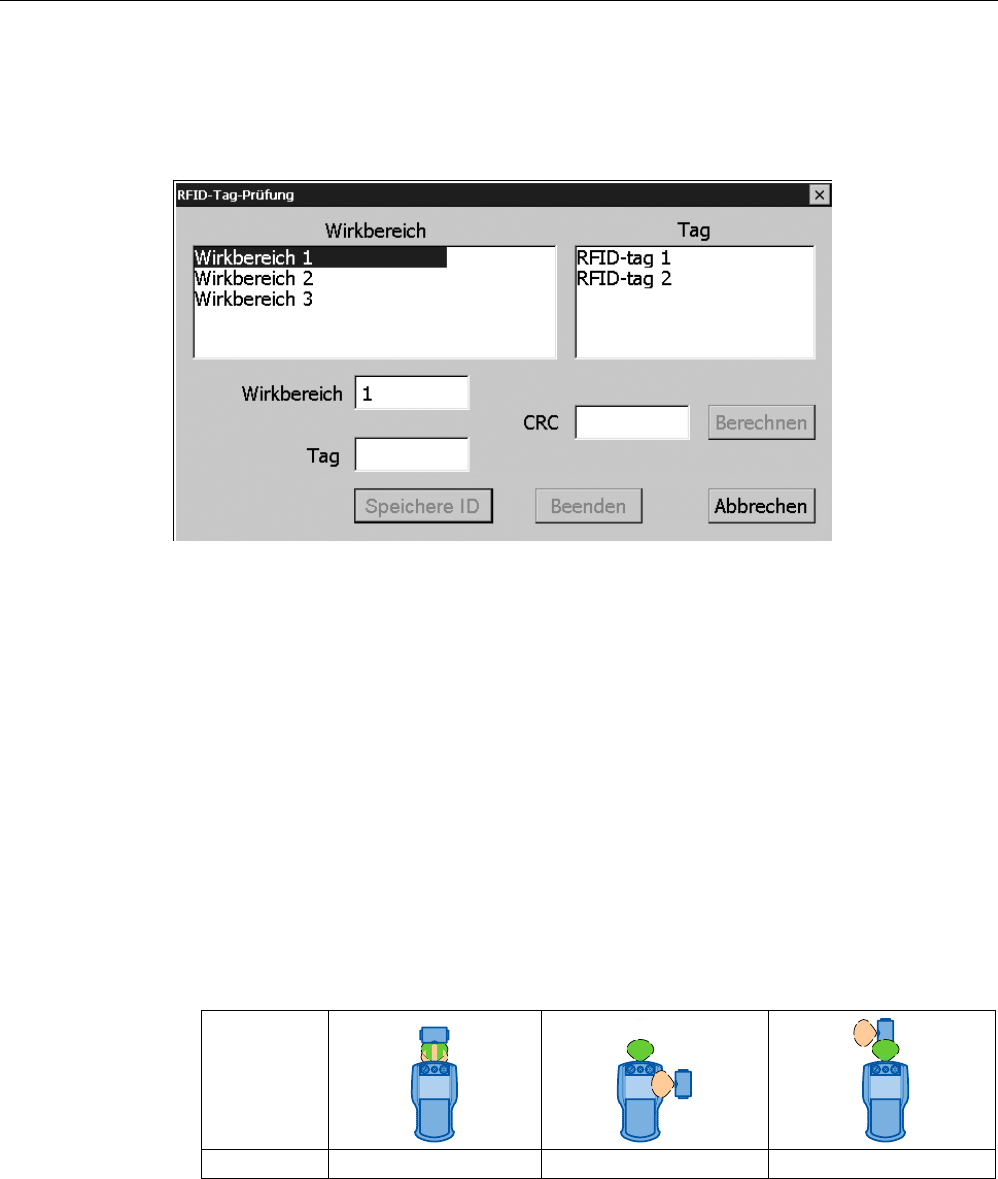
Commissioning a project
8.5 Commissioning an RFID tag
Wireless Teach Pendant F IWLAN V2
200 Operating Instructions, 08/2010, A5E02453837-01
Requirement
A project with configured effective ranges and RFID tags has been transferred to the HMI
device. The project starts immediately after transfer. The following dialog is displayed.
The dialog shows the configured effective ranges and RFID tags with their assigned IDs in
the project.
Procedure
To recommission the RFID tags, proceed as follows:
1. Select an effective range in the "Effective range" list.
The "Tag" list shows the RFID tags that are assigned to this effective range in the WinCC
flexible project. The "Effective range" box shows the configured ID of the selected
effective range.
2. In the "Tag" list, select the RFID tag to which you want to assign an ID.
The "Tag" box shows the configured ID of the selected RFID tag.
3. Bring the HMI device into the immediate proximity of the RFID tag, in other words, into
the effective range of the RFID tag to which you want to assign the ID shown in the "Tag"
box.
The following table shows how to align the HMI device to the RFID tag.
Alignment
Logon Possible Not supported Not supported
PRELIMINARY II
1.7.2010