Siemens WTPIWLAN-V200 SIMATIC WTP 277F IWLAN User Manual Wireless Teach Pendant F IWLAN V2
Siemens AG SIMATIC WTP 277F IWLAN Wireless Teach Pendant F IWLAN V2
Siemens >
Contents
- 1. Users Manual p1
- 2. Users Manual p2
- 3. Users Manual p3
Users Manual p3
Commissioning a project
8.5 Commissioning an RFID tag
Wireless Teach Pendant F IWLAN V2
Operating Instructions, 08/2010, A5E02453837-01 201
4. Press "Save ID".
The ID is sent to the RFID tag and stored there. A check mark is set in the "Tag" list, if the
configured tag ID is successfully written to the RFID tag.
NOTICE
Recording the ID of the RFID tag
If you replace the RFID tag at a later date due to a defect, for example, you will always
need the ID of the RFID tag.
Therefore, record the ID of the RFID tag so that it is at hand at all times. For example,
write it on the front of the RFID tag using a permanent marker.
5. Repeat steps 2 to 4 for all RDIF tags of this effective range.
When all the RFID tags of an effective range have an ID, the selected effective range has
a check mark in the "Effective range" list.
6. Repeat steps 1 to 5 for all effective ranges.
The "Calculate" button is gray and only becomes black again, and thus enabled, when all
RFID tags have successfully been assigned an ID.
7. Press "Calculate".
The CRC checksum is displayed.
8. Record the checksum or enter it immediately in "Effective ranges (RIFD)" in the
WinCC flexible editor.
9. Click "Exit" to close the dialog.
Result
You have assigned a unique identifier to all RFID tags and determined a checksum.
Transfer the project with the added CRC checksum again to the HMI device. You can log
onto a machine and operate the machine in fail-safe mode.
See also
Replacing an RFID tag (Page 202)
PRELIMINARY II
1.7.2010
Commissioning a project
8.6 Replacing an RFID tag
Wireless Teach Pendant F IWLAN V2
202 Operating Instructions, 08/2010, A5E02453837-01
8.6 Replacing an RFID tag
If it is not possible to log onto an effective range, the HMI device or RFID tag may be
defective. This section describes the configuration work carried out after replacement of a
defective RFID tag.
Requirement ● The defective RFID tag has been replaced.
● The ID of the defective RFID tag is available.
● The project, in which the RFID tag has failed, is still on the HMI device.
Procedure Proceed as follows:
1. Switch on the HMI device.
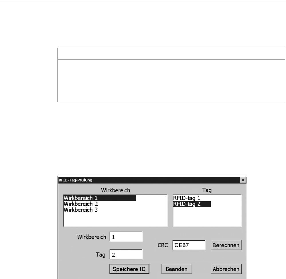
2. Open the Control Panel.
3. Press the "RFID Config" icon.
The following dialog appears:
4. Select the effective range ID in the "Effective range" selection box and the ID of the
defective RFID tag in the "Tag" selection box.
5. Bring the HMI device into the effective range of the RFID tag.
6. Press "Save ID".
The HMI device transmits the ID to the RFID tag. The new RFID tag has the ID of the
previously used RFID tags.
7. Click "Exit" to close the dialog.
8. Close the Control Panel and start the project.
9. Log the HMI device onto a machine to check the new RFID tag.
– When the logon is successful, you can continue working in the project.
– If logon is not possible close the dialog and repeat steps 2 to 8.
PRELIMINARY II
1.7.2010

Wireless Teach Pendant F IWLAN V2
Operating Instructions, 08/2010, A5E02453837-01 203
Commissioning the plant 9
9.1 Overview
The acceptance of the plant involves the following:
● Safety-related project
● Safety program
● RFID tags with effective ranges
9.2 Acceptance of the plant
All of the relevant application-specific standards and the procedure described in this section
must be observed in the course of final acceptance of the plant.
Note
This section provides a detailed description of the additional tasks required for the fail-safe
operation of the HMI device.
Read the detailed description provided in the "System Acceptance Test" section of the
"S7 Distributed Safety, Configuring and Programming" manual when performing an
acceptance procedure for the plant.
The acceptance of the plant involves the following tasks:
● Configure the F-CPU and F-I/O
● Create a safety program
Requirement ● The hardware configuration has been created in HW Config.
● The safety program has been created and generated.
● A backup of the STEP 7 project has been created.
Configuring the F-CPU and F-I/O
● Printing and archiving the hardware configuration.
● Check the following parameters in the hardware configuration:
– Parameters of the F-CPU
– Parameters of the F-I/O
This includes unique PROFIsafe addresses and additional PROFIsafe parameters.
● Save the hardware configuration with the STEP 7 project.
A detailed description is provided in the "Acceptance test for the configuration of the F-CPU
and the F-I/O" section of the "S7 Distributed Safety, Configuring and Programming" manual.
PRELIMINARY II
1.7.2010

Commissioning the plant
9.3 Diagnostics
Wireless Teach Pendant F IWLAN V2
204 Operating Instructions, 08/2010, A5E02453837-01
Acceptance of the safety program
● Print and archive the safety program.
● Check the printed copy of the safety program for existence of the criteria specified in the
"S7 Distributed Safety, Configuring and Programming" manual, section "Acceptance of a
safety program."
● Download the entire safety program to the F-CPU.
● Test all functions of the safety program.
A detailed description is provided in the "Acceptance test for the configuration of the F-CPU
and the F-I/O" section of the "S7 Distributed Safety, Configuring and Programming" manual.
See also
Programming and operation manual "S7 Distributed Safety - Configuring and Programming"
(http://support.automation.siemens.com/WW/view/en/22099875)
9.3 Diagnostics
Use the diagnostics function to determine the following:
● Does signal acquisition function without errors on the HMI device?
● Does the safety-related module of the HMI device work properly?
Diagnostic function of the HMI device in STEP 7
The HMI device provides diagnostics conforming to PROFINET IO standard IEC 61784-1,
Ed1, CP 3/3 for standard application.
The diagnostics function cannot be parameterized. The diagnostics are always enabled and
information is provided automatically by the HMI device in STEP 7 in the event of an error.
The diagnostic function also passes the "Communication error" message, if at all possible,
for the safety-related component.
The communication between the HMI device as an input and output device, and the F-CPU
and IO controller is disrupted. This situation can be caused, for example, by an incorrect
PROFIsafe address or the lack of a wireless network.
Reading diagnostics information
Open the module diagnostics in STEP 7 to determine the cause of the error. For additional
information, refer to the online help for STEP 7.
You also have the option of reading the diagnostic information using SFB 52 or SFB 54 in
the standard user program. For additional information, refer to the "System and Standard
Functions" reference manual.
PRELIMINARY II
1.7.2010

Commissioning the plant
9.3 Diagnostics
Wireless Teach Pendant F IWLAN V2
Operating Instructions, 08/2010, A5E02453837-01 205
Diagnostic information for internal errors
All LEDs of the LED display go out when an internal error of the HMI device causes a failure.
When a project is running on the HMI device, the following occurs:
● The project is closed.
● The following error code message is displayed on the HMI device:
A severe problem has occurred!
Date: 2010-04-30 09:18
ErrorCode: 000 0008 00006 01506
Please report this error code to your technical support
http://www.siemens.de/automation/support-request
Procedure
Proceed as follows:
1. Record the error number – see Error Code.
2. Switch off the HMI device.
3. Restart the HMI device.
Contact Technical Support
(http://support.automation.siemens.com/WW/llisapi.dll?aktprim=99&lang=en&referer=%2f
WW%2f&func=cslib.csinfo2&siteid=csius&extranet=standard&viewreg=WW) if the error
persists. Based on the error code, Technical Support can come to a conclusion about the
type of internal error.
PRELIMINARY II
1.7.2010

Commissioning the plant
9.3 Diagnostics
Wireless Teach Pendant F IWLAN V2
206 Operating Instructions, 08/2010, A5E02453837-01
Error code for discrepancy errors
The following table lists the error codes for discrepancy errors. You may be able to find a
remedy for a discrepancy error yourself, depending on the situation. The first six digits of the
error code are decisive for the correct identification of the error.
Error code Error type Remedy
000 008 Discrepancy error at the EMERGENCY
STOP button
Release the EMERGENCY STOP button.
000 014 Discrepancy error at the right enabling
button, Panic switch position
000 015 Discrepancy error at the left enabling
button, Panic switch position
Make sure that the button does not
become askew when it is pressed.
The terms "left" and "right" enabling buttons refer to your position facing the display of the
HMI device.
See also
Discrepancy error during enabling (Page 258)
PRELIMINARY II
1.7.2010
Wireless Teach Pendant F IWLAN V2
Operating Instructions, 08/2010, A5E02453837-01 207
Fail-safe operation 10
10.1 Organizational measures
The HMI device should only be operated in the plant with a main rechargeable battery or in
the docking station.
You must adhere to the organizational measures described in this section to ensure fail-safe
operation of the HMI device.
WARNING
EMERGENCY STOP button out of service when HMI device is removed
If the HMI device is not integrated in the safety program of the F-CPU, the EMERGENCY
STOP button will be out of service.
To avoid confusion between HMI devices with enabled and disabled EMERGENCY STOP
buttons, only one integrated HMI device should be freely accessible.
If an HMI device is not integrated and not in use, store the HMI device in a location with
protected access.
Handling the HMI device during operation
CAUTION
Shutdown or global rampdown may occur with an empty main rechargeable battery
An integrated HMI device with an empty main rechargeable battery triggers a
communication error. This error results in the following reaction of the F-CPU:
When the HMI device is logged onto a machine – shutdown
When the HMI device is not logged onto a machine – global rampdown
Check the charge of the main rechargeable battery at brief intervals using the "BAT" LED.
Note
It is prohibited to leave the protection zone without an HMI device while the HMI device is
logged onto a machine.
Log off the HMI device from the machine before you leave the protection zone.
Pay attention to the LED display of the HMI device – see section "LED display (Page 85)".
PRELIMINARY II
1.7.2010
Fail-safe operation
10.2 Switch-off behavior
Wireless Teach Pendant F IWLAN V2
208 Operating Instructions, 08/2010, A5E02453837-01
10.2 Switch-off behavior
The shutdown reaction of the plant will vary according to cause and effect.
DANGER
Shutdown
The shutdown response described in the next sections is only triggered in the plant if the F-
CPU has been programmed accordingly.
Programming the F-CPU accordingly.
The following types of shutdown may occur depending on the operating state of the plant:
● EMERGENCY STOP
● Global rampdown
● Local rampdown
● Shutdown
The following table shows the shutdown reaction depending on the operating state and the
cause:
Cause of the shutdown Operating state
EMERGENCY STOP
button pressed
Communication error
HMI not integrated – –
HMI device is in the
protection zone
EMERGENCY STOP Shutdown HMI device is
logged onto a
machine HMI device is
outside the
protection zone
EMERGENCY STOP Shutdown
HMI
integrated
HMI device is logged off from the
machine
EMERGENCY STOP Global rampdown
See also Terms for fail-safe operation (Page 32)
PRELIMINARY II
1.7.2010
Fail-safe operation
10.3 Integrating the HMI device
Wireless Teach Pendant F IWLAN V2
Operating Instructions, 08/2010, A5E02453837-01 209
10.3 Integrating the HMI device
During fail-safe operation, a safety program runs in the F-CPU. The HMI device is integrated
into this safety program. The HMI device and F-CPU communicate via PROFINET IO.
When there is a project for a safety program on the HMI device, it is automatically integrated
following the start of the project. The "SAFE" LED lights up to indicate that integration is
complete.
The EMERGENCY STOP button is enabled as soon as the HMI device is integrated.
Requirement
● WLAN
● PROFIsafe safety-related bus profile, as of V2.0
● The plant has been accepted.
● The loader is displayed on the HMI device.
Procedure
Proceed as follows:
1. Start the project.
PROFIsafe communication is established. While the connection is being established, the
"Establishing secure connection" dialog is displayed with the following symbol.
The HMI device is integrated in the safety program of the F-CPU.
The "SAFE" LED lights up.
The "Test enabling switch" dialog is displayed with the following symbol.
2. Fully press down both enabling buttons.
The project start screen appears.
PRELIMINARY II
1.7.2010
Fail-safe operation
10.4 Logging onto a machine
Wireless Teach Pendant F IWLAN V2
210 Operating Instructions, 08/2010, A5E02453837-01
10.4 Logging onto a machine
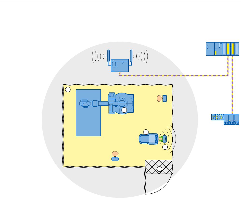
The following figure shows the logon of an HMI device to a machine within a protection zone.
352),VDIH
① Protection zone
② Machine
③ HMI device
④ RFID tag 1
⑤ Access monitoring
Requirement
● WLAN connection
● RFID tags have been commissioned
● The HMI device is integrated
PRELIMINARY II
1.7.2010
Fail-safe operation
10.4 Logging onto a machine
Wireless Teach Pendant F IWLAN V2
Operating Instructions, 08/2010, A5E02453837-01 211
Procedure
Proceed as follows:
1. Switch to the screen that contains the "Effective range name (RFID)" button labeled
"Scan".
6FDQ
2. Bring the HMI device into the effective range of the RFID tag to which you want to log on,
for example, "RFID Tag 1".
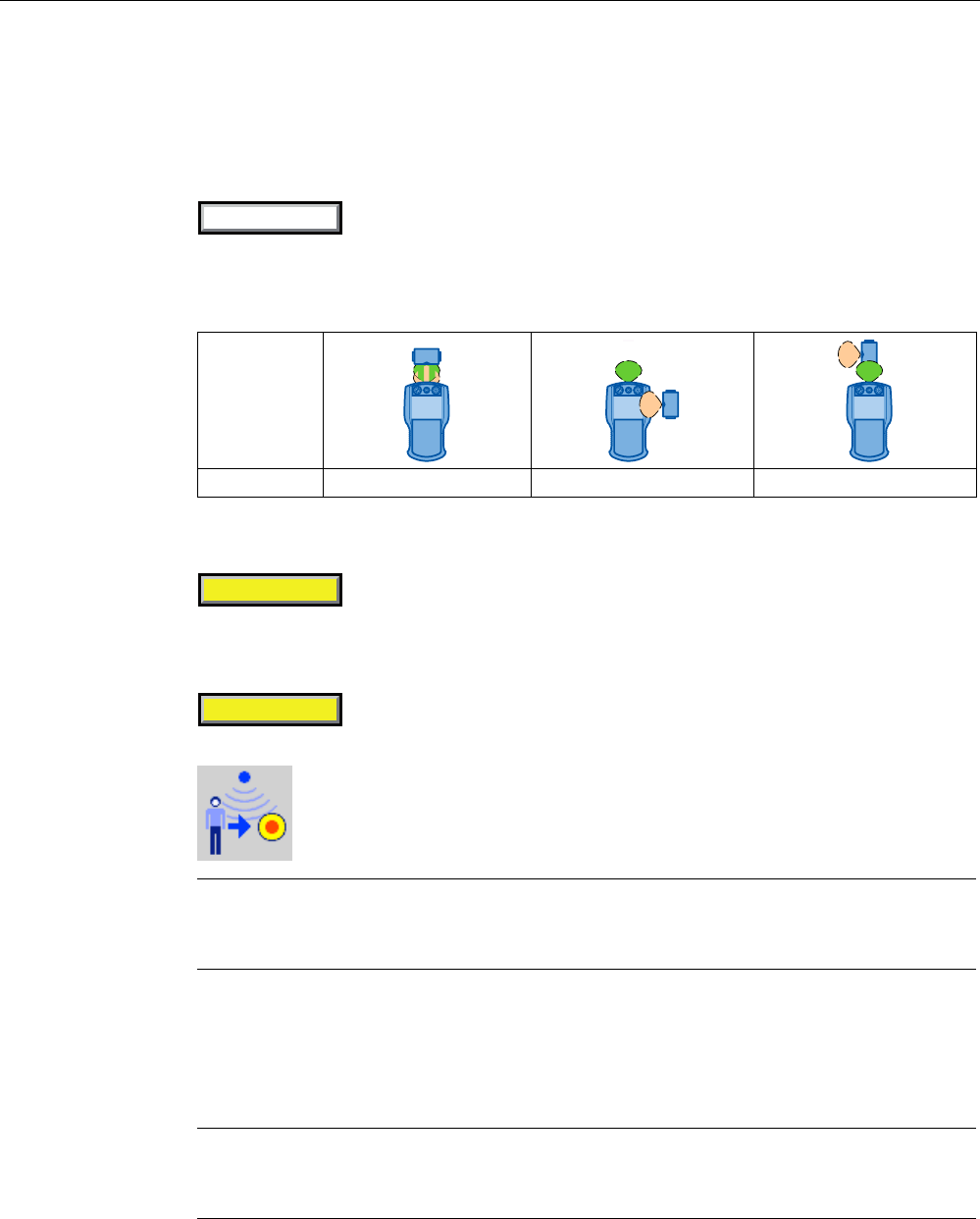
The following table shows how to align the HMI device to the RFID tag.
Alignment
Logon Possible Not supported Not supported
3. Press the button labeled "Scan".
During the scan procedure, the button is yellow and displays the text, "Scanning...".
6FDQQLQJ
The HMI device reads the ID from the RFID tag. After the data transfer, the name of the
effective range will be briefly displayed on the "Effective range name (RFID)" operator
control, for example, "Robot 1".
5RERW
The "Effective range logon" dialog is then displayed with the following symbol.
Note
As soon as the "Effective range logon" dialog is displayed, you can remove the HMI
device from the effective range of the RFID tag.
4. Enter the ID of the effective range in the text box.
The ID of the effective range is located on the label of the RFID tag.
5. Confirm the entry with "OK".
The dialog closes.
Note
A message appears if the ID of the effective range is incorrect. The corresponding dialog
must be acknowledged. Repeat the logon to the effective range with a valid ID.
PRELIMINARY II
1.7.2010
Fail-safe operation
10.5 Logging off the machine
Wireless Teach Pendant F IWLAN V2
212 Operating Instructions, 08/2010, A5E02453837-01
The "Confirmation of logon" dialog is displayed with the following symbol.
6. Confirm the logon with the enabling button.
The successful logon is indicated by the "RNG" LED on the HMI device.
Result
You are logged onto the machine and the machine can operate within the protection zone in
fail-safe mode. The "Effective range name (RFID)" operator control is shown in green and
labeled with the name of the effective range.
The following figure shows the "Effective range name (RFID)" object after logon to an
effective range with the name "Robot 1".
5RERW
10.5 Logging off the machine
You do not need to stand directly in front of the RFID tag to log off the machine you are
operating in fail-safe mode.
Procedure
Proceed as follows:
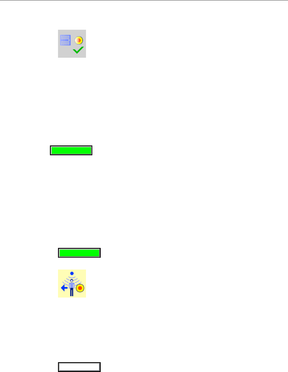
1. Press the "Effective range name (RFID)" operator control.
5DQJHQDPH
The "Effective range logoff" dialog is displayed with the following symbol.
2. Confirm the logoff from the machine with the "OK" button.
The "RNG" LED goes out when the logoff is successfully completed.
Result
● The HMI device is logged off the machine.
● The "Effective range name (RFID)" operator control is shown in white and labeled "Scan".
6FDQ
PRELIMINARY II
1.7.2010
Fail-safe operation
10.6 Removing the HMI device
Wireless Teach Pendant F IWLAN V2
Operating Instructions, 08/2010, A5E02453837-01 213
10.6 Removing the HMI device
You have the following options for removing the HMI device:
● Close the project.
● Press and hold the "ON/OFF" button for at least 4 seconds.
WARNING
EMERGENCY STOP button out of service when HMI device is removed
If the HMI device is not integrated in the safety program of the F-CPU, the
EMERGENCY STOP button will be out of service.
To avoid confusion between HMI devices with enabled and disabled EMERGENCY
STOP buttons, only one integrated HMI device should be freely accessible.
If an HMI device is not integrated and not in use, store the HMI device in a location with
protected access.
Requirement
● The project must be started.
● The HMI device is integrated into the safety program of the F-CPU.
● The HMI device is not logged onto a machine.
Procedure
Proceed as follows:
1. Close all open dialogs.
2. Close the project using the operator control designed for this purpose or press the
"ON/OFF" button for more than 4 seconds.
The "Start removal" dialog is displayed with the following symbol.
3. Use the "Yes" button to confirm the removal.
The "Confirm removal" dialog opens with the following symbol.
4. Press an enabling button within 60 seconds.
PRELIMINARY II
1.7.2010

Fail-safe operation
10.6 Removing the HMI device
Wireless Teach Pendant F IWLAN V2
214 Operating Instructions, 08/2010, A5E02453837-01
NOTICE
Global rampdown
A global rampdown will occur, if you do not confirm the "Confirm removal" dialog within
60 seconds with the enabling button.
Press an enabling button within 60 seconds.
The "Confirm removal" dialog closes.
– The "SAFE" LED on the HMI device goes out.
– PROFIsafe communication is terminated.
– The HMI device has been successfully removed from the safety program of the F-
CPU.
– The project is closed.
– If you have pressed the ON/OFF" button during step 1, the HMI device switches off.
PRELIMINARY II
1.7.2010

Wireless Teach Pendant F IWLAN V2
Operating Instructions, 08/2010, A5E02453837-01 215
Operating a project 11
11.1 Starting the project
Note
A project may demand operator actions that require in-depth knowledge of the specific plant
on part of the operator. Proceed with caution, for example, when you use jog mode. Refer to
your plant documentation for additional information.
Requirement
The following requirements have to be met to start the project:
● The plant has been accepted.
● The main rechargeable battery is charged and inserted in the HMI device.
If no main rechargeable battery is available, place the HMI device in the docking station.
● The radio signal from the WLAN is sufficiently strong.
● The PROFIsafe address is configured on the HMI device.
● The data channel is configured on the HMI device.
● The project has been transferred to the HMI device.
PRELIMINARY II
1.7.2010

Operating a project
11.1 Starting the project
Wireless Teach Pendant F IWLAN V2
216 Operating Instructions, 08/2010, A5E02453837-01
Procedure
Proceed as follows:
1. Press the "ON/OFF" button.
The HMI device performs the following tasks:
– The HMI device starts.
– The "PWR" LED lights up.
– The "BAT" LED shows the remaining charge of the main rechargeable battery.
– The WLAN connection is established.
The "COM" LED flashes while the connection is being established.
The "COM" LED lights up when the WLAN connection is established.
The project is started.
– PROFIsafe communication is established.
The "Establishment of safety connection" dialog is displayed. The HMI device is
integrated once the PROFIsafe connection has been successfully established.
The "SAFE" LED lights up.
The EMERGENCY STOP button is enabled.
– The "Test enabling button" dialog is displayed.
2. Fully press down both enabling buttons.
Result
The HMI device displays the start screen of the project.
Log onto a machine to enable the enabling button.
See also
Logging onto a machine (Page 210)
PRELIMINARY II
1.7.2010

Operating a project
11.2 Operator input options
Wireless Teach Pendant F IWLAN V2
Operating Instructions, 08/2010, A5E02453837-01 217
11.2 Operator input options
A project may demand operator actions that require in-depth knowledge of the specific plant
on part of the operator. Proceed with caution, for example, when you use jog mode. Refer to
your plant documentation for additional information.
CAUTION
Unintentional action
If you press several operator controls at once, you may trigger an unintentional action.
Do not carry out several operations simultaneously.
When using the touch screen:
Never press more than one operator control on the touch screen at once.
When using an external keyboard:
Do not press more than two keys at once
Operator input options
Once the project is transferred to the HMI device, you can operate and monitor active
processes during the process control phase. You have the following operating options:
● Touch screen
The operator controls shown in the configured screens are touch-sensitive. Touch objects
are operated in the same way as mechanical keys. You trigger an operator control by
pressing it with your finger. To double-click an operator control, you tap it twice in quick
succession.
● Membrane keyboard
You can use the numeric area of the membrane keyboard to enter numeric values.
Note
Read the section "Overview (Page 83)".
● USB keyboard
You can operate the Windows CE interface and Control Panel with an external keyboard
in the exact same way as you do with the screen keyboard of the HMI device.
● USB mouse
You can operate the Windows CE interface and Control Panel with an external mouse in
the exact same way as you do with the touch screen of the HMI device.
PRELIMINARY II
1.7.2010

Operating a project
11.2 Operator input options
Wireless Teach Pendant F IWLAN V2
218 Operating Instructions, 08/2010, A5E02453837-01
Feedback from an operator control
The HMI device provides optical feedback as soon as it detects that an operator controls has
been selected. The operator control receives the focus and is selected. The selection is
independent of any communication with a PLC. Therefore this selection does not indicate
whether the relevant action is actually executed or not.
The selection of an operator control can deviate from the standard. Refer to your plant
documentation for additional information.
The type of optical operation feedback depends on the operator control:
● Button
If the configuration engineer has configured a 3D effect, the button appears differently
depending on the "Pressed" and "Not pressed" states:
– "Pressed" state
– "Not pressed" state
The line width and color of the button are set during the configuration.
● Invisible button
By default, an invisible button is displayed as not pressed when it is selected. There is no
optical operation feedback.
The configuration engineer may, however, configure invisible buttons so that their outline
appears as lines when they are pressed. This lines will remain visible until you press
another operator control.
● I/O field
When you select an I/O field, the content of the I/O field is displayed against a colored
background. With touch operation, a screen keyboard is displayed for the entering of
values.
PRELIMINARY II
1.7.2010

Operating a project
11.3 Direct keys
Wireless Teach Pendant F IWLAN V2
Operating Instructions, 08/2010, A5E02453837-01 219
11.3 Direct keys
A direct key on the HMI device is a direct way to set a bit in the I/O area of the controller. A
direct key enables an operation with a fast response time. Fast response time is essential,
for example, for jogging mode.
NOTICE
Leaving the WLAN
Note that leaving the WLAN area will cause the PROFINET IO device to fail and therefore
result in a PLC stop.
Determine suitable programming measures in the PLC, in order to prevent a PLC stop.
Refer to your plant documentation for additional information.
Pressing a direct key
If you trigger an operator control with direct key functionality in an active project, the
corresponding function is always executed, regardless of the screen display at the time.
Avoid pressing a direct key unintentionally.
Note
A direct key is enabled when both of the following conditions are satisfied:
The HMI device is in the WLAN with sufficient radio signal.
The HMI device is in "Offline" mode.
The following objects can be configured as a direct key:
● Button
● Screen number
● Illuminated pushbutton
● Rotary switch
Note
Direct keys result in additional basic load on the HMI device.
Additional information is available in the "WinCC flexible, Communication" system manual.
PRELIMINARY II
1.7.2010

Operating a project
11.4 Setting the project language
Wireless Teach Pendant F IWLAN V2
220 Operating Instructions, 08/2010, A5E02453837-01
11.4 Setting the project language
The HMI device supports multilingual projects. You must have configured a corresponding
operator control which lets you change the language setting on the HMI device during
runtime.
The project always starts with the language set in the previous session.
Requirement
● The required language for the project must be available on the HMI device
● The language switching function must be logically linked to a configured operator control
such as a button
Selecting a language
You can change project languages at any time. Language-specific objects are immediately
output to the screen in the new language when you switch languages.
The following options are available for switching the language:
● A configured operator control switches from one language to the next in a list
● A configured operator control directly sets the desired language
More detailed information is available in your plant documentation.
11.5 Operating the screen keyboard in the project
If you do not use an external keyboard, use the screen keyboard to enter numeric and
alphanumeric characters. As soon as you touch a text box, a numeric or alphanumeric
screen keyboard is displayed, depending on the type of the text box.
Display methods for the screen keyboard
You can change the type of display for the screen keyboard and move its position on the
screen.
● Numerical screen keyboard
PRELIMINARY II
1.7.2010
Operating a project
11.5 Operating the screen keyboard in the project
Wireless Teach Pendant F IWLAN V2
Operating Instructions, 08/2010, A5E02453837-01 221
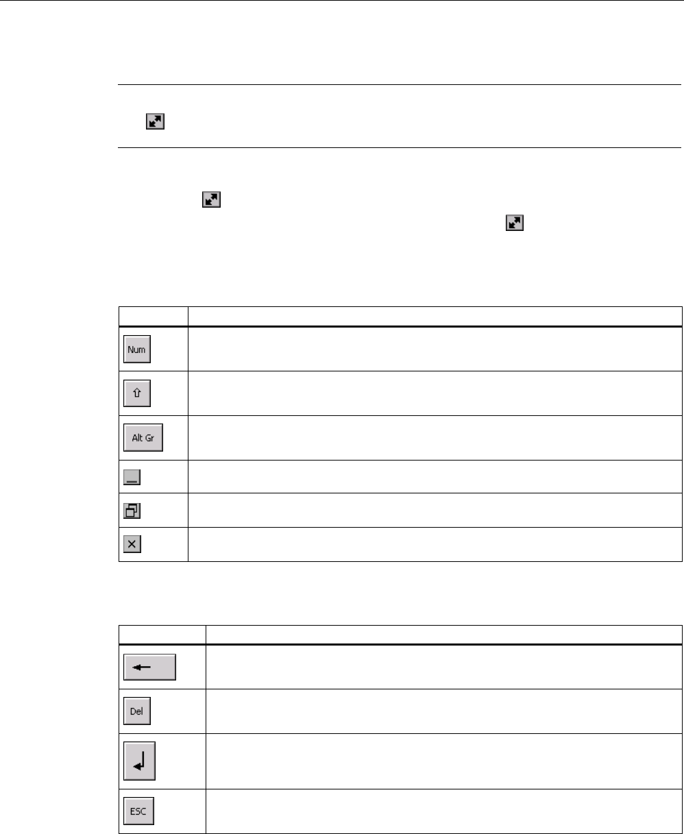
● Alphanumerical screen keyboard
The alphanumerical screen keyboard has the following levels.
– Normal level
– Shift level
The shift level includes uppercase letters.
– Special character level
Note
The ' character (button between ";" and "\") appears only when followed by a space. If
the ' character is followed by a letter, then the result will be an accent, such as "á".
● Reduced screen keyboard
Note
When the screen keyboard is open, PLC job 51, "Select screen" has no function.
The screen keyboard display is independent of the configured project language.
Language switching in the project has no influence on the alphanumerical screen
keyboard. This means you cannot enter Cyrillic or Asian characters.
Procedure for moving the screen keyboard
Proceed as follows:
1. Touch the symbol and move the screen keyboard on the touch screen.
2. When the desired position is reached, release the icon .
PRELIMINARY II
1.7.2010
Operating a project
11.5 Operating the screen keyboard in the project
Wireless Teach Pendant F IWLAN V2
222 Operating Instructions, 08/2010, A5E02453837-01
Procedure for adjusting the size of the screen keyboard
Note
The icon only appears on the screen keyboard if in the "Siemens HMI InputPanel" dialog
you have selected the "Show Resize button" check box.
Proceed as follows:
1. Touch the symbol and drag the screen keyboard to the appropriate size.
2. When the size you want is reached, release contact with the icon.
Changing the display of the screen keyboard
Key Function
Switching between the numerical and alphanumerical keyboard
Switching between the normal level and Shift level of the alphanumerical screen
keyboard
Switchover to special characters
Switching from full display to reduced display
Switching from reduced display to full display
Closing of reduced display of the screen keyboard
Entering data
Key Function
Delete character left of cursor
Delete character right of cursor
Confirm entry and close the screen keyboard
Cancel input
PRELIMINARY II
1.7.2010
Operating a project
11.5 Operating the screen keyboard in the project
Wireless Teach Pendant F IWLAN V2
Operating Instructions, 08/2010, A5E02453837-01 223
Note
Data input - numerical text box
Hexadecimal values
When you enter a value in hexadecimal format, the alphanumerical screen keyboard
opens.
Decimal places
The configuration engineer can define the number of decimal places for a numerical text
box. The number of decimal places is checked when you enter a value in this type of I/O
field.
– Decimal places in excess of the limit are ignored.
– Empty decimal places are filled with "0".
Limits
A tag can be configured with limits. If you enter a value outside these limits, it will be
rejected.
If an alarm view is configured, a system event is triggered and the original value is
displayed again.
Data input – date and time
When entering the date and time, note that their format is determined by the configured
project language.
Opening the Windows CE taskbar
You open the Windows CE taskbar with the key.
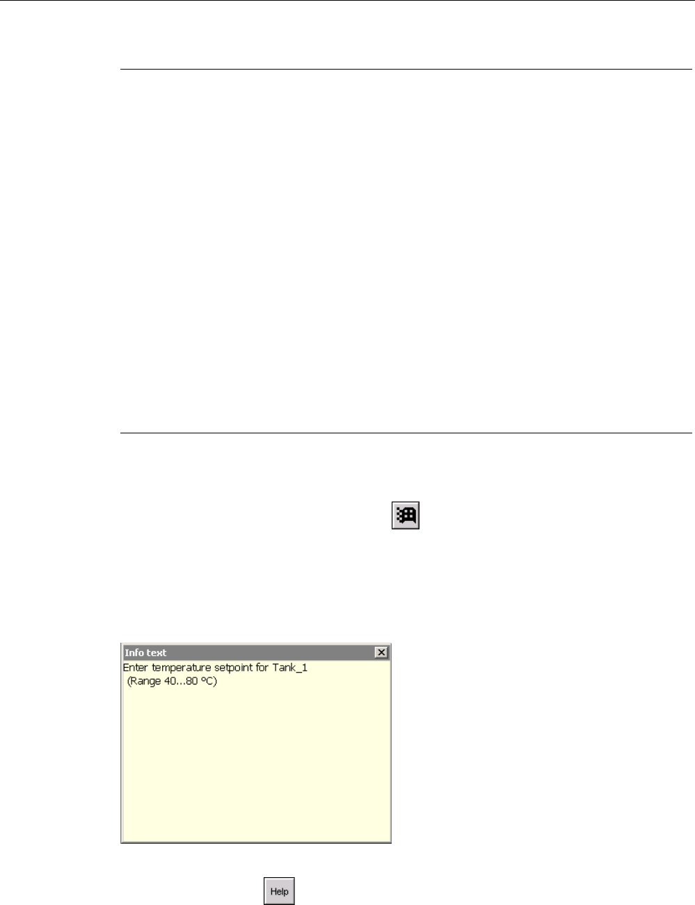
Displaying infotext
The configuration engineer uses infotext to provide additional information and operating
instructions. There may be infotext for HMI screens and operator controls in the project.
The infotext for an I/O field may contain, for example, information on the value to be entered.
The screen keyboard appears on the HMI device touch screen when you touch an operator
control that requires input. If an infotext was configured for the current operator control, call
up the infotext with the button. If no infotext is available for the current operator control,
the infotext for the current HMI screen will be displayed.
PRELIMINARY II
1.7.2010
Operating a project
11.6 Device-specific displays
Wireless Teach Pendant F IWLAN V2
224 Operating Instructions, 08/2010, A5E02453837-01
Note
If an infotext was configured for the current control object as well as the current HMI screen,
you can switch between both infotexts by touching the infotext window.
Close the infotext window with the button.
Depending on the project, infotext can also be called by an operator control configured for
this purpose. For additional information, refer to the online help of WinCC flexible.
11.6 Device-specific displays
11.6.1 Overview
This section describes the device-specific WinCC flexible objects, which you can use in a
project for the Wireless Teach Pendant F IWLAN.
For a full description of all WinCC flexible objects, refer to the online help of WinCC flexible.
11.6.2 Showing the battery charge
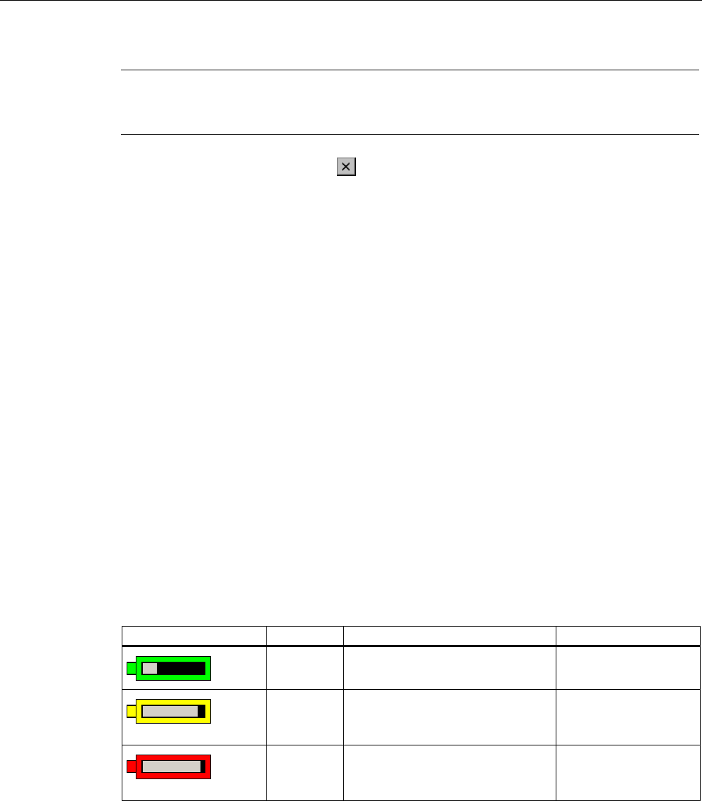
The "Battery" object indicates the remaining charge of the main rechargeable battery.
Charge the main rechargeable battery in time or replace it. Read the information provided in
section "Replacing and charging the main rechargeable battery (Page 72)".
The amount of charge for the main rechargeable battery is shown by the "Battery" object as
follows:
Icon Color Meaning Charge level
Green The main rechargeable battery is
sufficiently charged.
> 20 %
Yellow The charge is low.
The main rechargeable battery
must be charged or replaced.
6% to 20 %
Red The charge is very low.
The main rechargeable battery
must be charged or replaced.
< 6 %
See also Displaying the charge status of the batteries (Page 138)
PRELIMINARY II
1.7.2010

Operating a project
11.6 Device-specific displays
Wireless Teach Pendant F IWLAN V2
Operating Instructions, 08/2010, A5E02453837-01 225
11.6.3 Displaying WLAN quality
The "WLAN quality" object indicates the signal strength of the wireless network at the
location of the HMI device. The HMI device measures the signal strength and depicts it with
the "WLAN quality" object.
The signal strength of wireless network is indicated by the "WLAN quality" object as follows:
Icon Meaning Signal strength
No wireless connection No signal
Very poor wireless connection ≤ 20%
Poor wireless connection ≤ 40%
> 20%
Wireless connection OK ≤ 60%
> 40%
Good wireless connection ≤ 80%
> 60%
Very good wireless connection > 80%
PRELIMINARY II
1.7.2010
Operating a project
11.7 Project security
Wireless Teach Pendant F IWLAN V2
226 Operating Instructions, 08/2010, A5E02453837-01
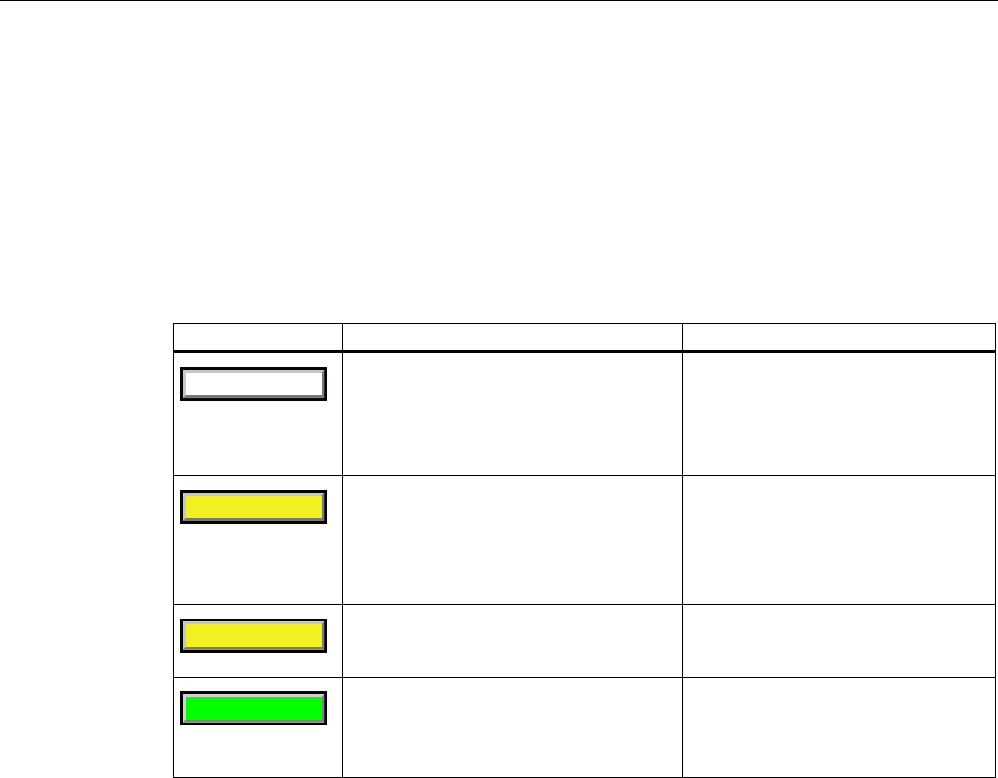
11.6.4 Displaying the "Effective range name (RFID)" object
The "Effective range name (RFID)" object is only available for an HMI device of the RFID tag
system. The "Effective range name (RFID)" object displays the following information:
● Logon status
● "Scan", "Scanning..." or name of the effective range associated with the machine on
which the HMI device is logged on
The "Effective range name (RFID)" object can show the following operating states:
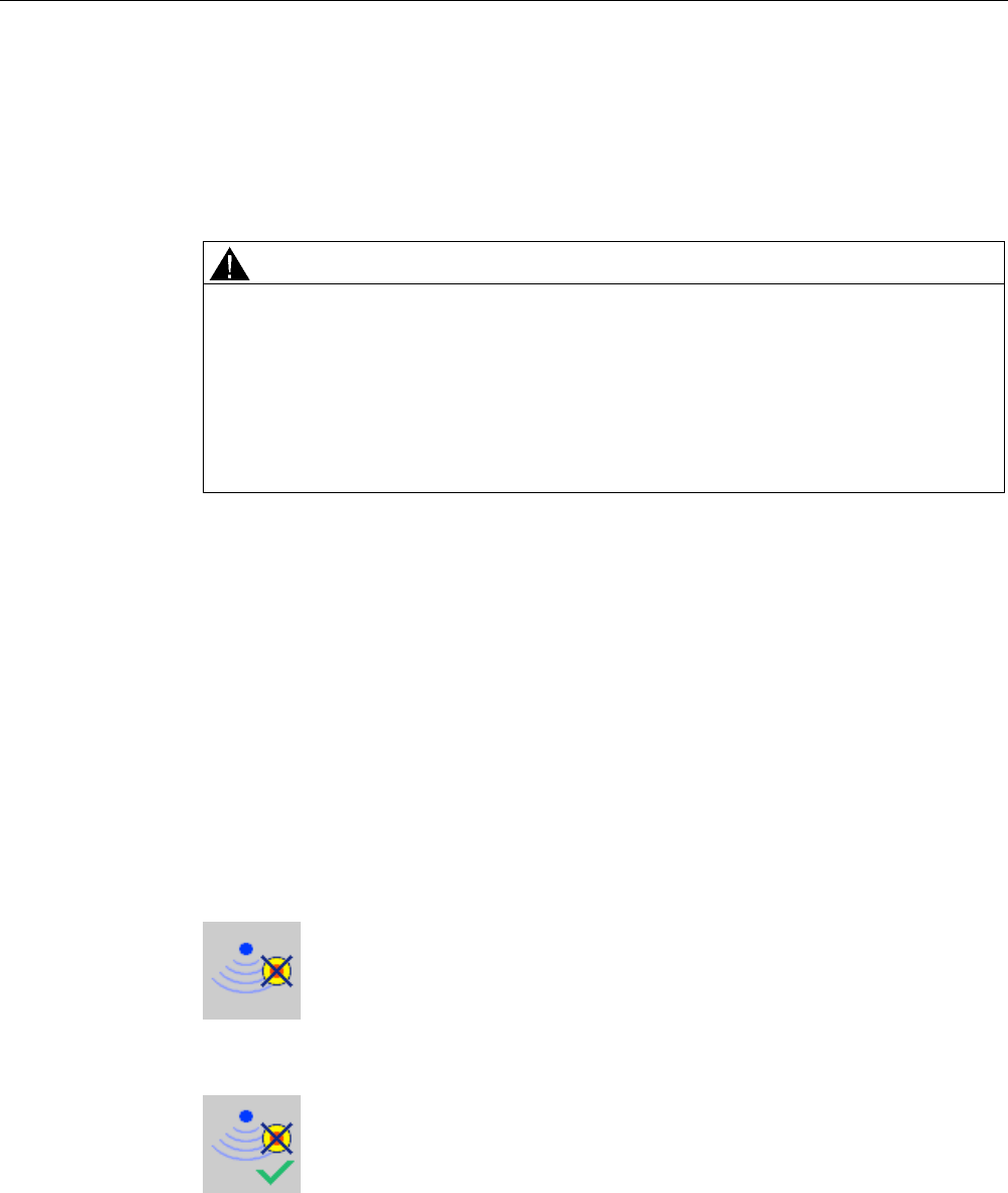
Icon Operating state Logon
6FDQ
The HMI device is not logged onto a
machine.
The enabling button is not enabled.
It is not possible to log onto a
machine.
To log onto a machine, the user must
press the operator control and
search for effective ranges.
6FDQQLQJ
The user has pressed the operator
control to search for effective ranges.
The HMI device searches for an
effective range.
The enabling button is not enabled.
Logon can only take place when the
HMI device has detected an effective
range.
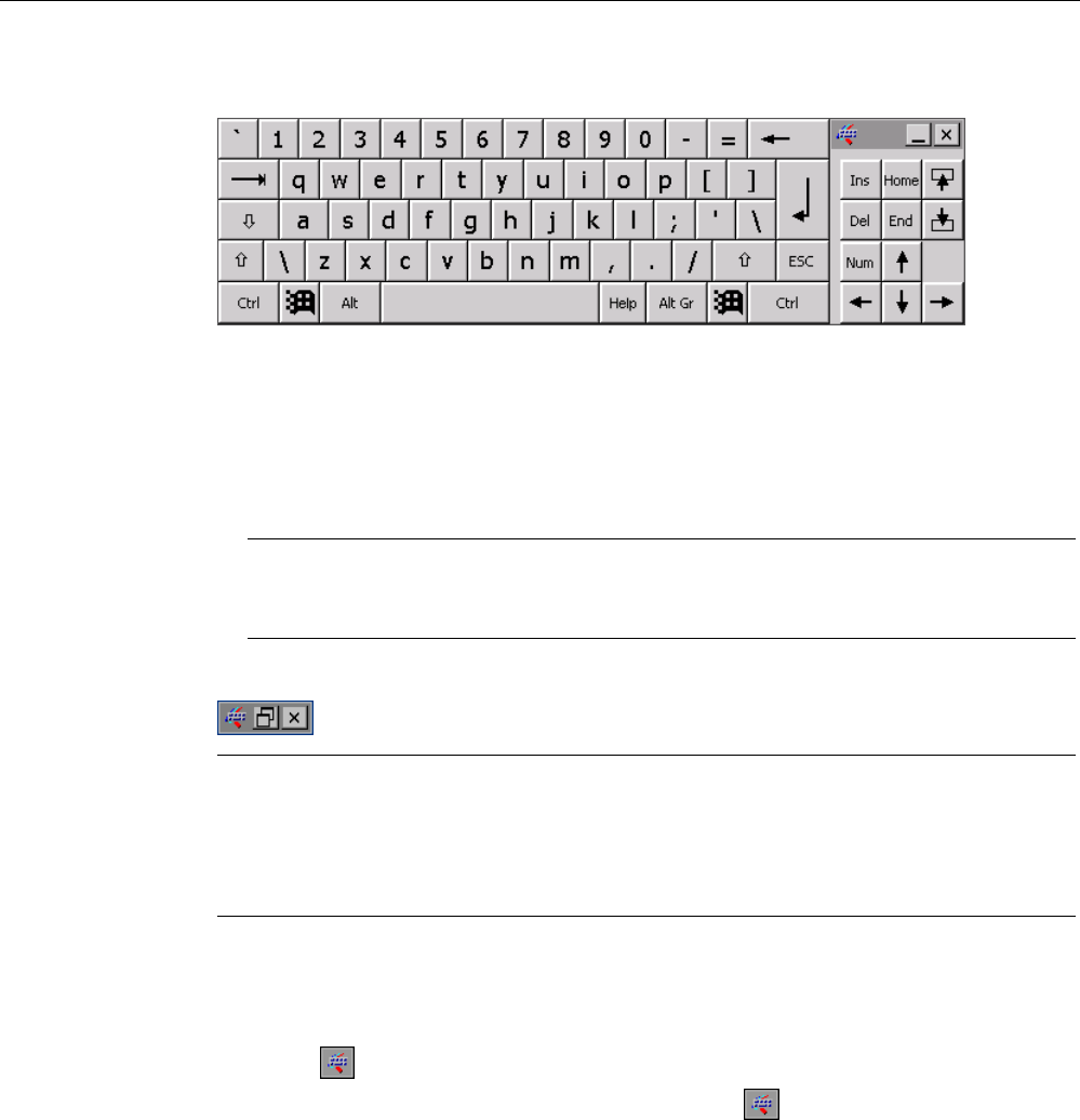
5RERW
The HMI device has detected the
effective range, "Robot 1".
The logon to the machine associated
with the "Robot 1" effective range is
possible.
5RERW
The user is logged onto the machine
associated with the "Robot 1" effective
range.
The enabling button is enabled.
–
11.7 Project security
11.7.1 Overview
Design of the security system
The configuration engineer can protect the operation of a project by implementing a security
system. The security system is based on authorizations, user groups and users.
If operator controls protected by a password are pressed, the HMI device first requests that
you log on. A logon screen is displayed in which you enter your user name and password.
After logging on, you can press the operator controls for which you have the necessary
authorizations.
The logon dialog can be set up by the configuration engineer via an individual operator
control. Similarly, an operator control can be configured for logoff. After logging off, objects
with password protection can no longer be operated – you need to log on again.
Refer to your plant documentation for additional information.
PRELIMINARY II
1.7.2010

Operating a project
11.7 Project security
Wireless Teach Pendant F IWLAN V2
Operating Instructions, 08/2010, A5E02453837-01 227
Central user administration using SIMATIC Logon
Users, user groups and authorizations can be stored on a central server.
If user administration cannot contact the server, an error message is displayed. If this is the
case, you can only log on locally. More detailed information is available in your plant
documentation.
The operation of SIMATIC Logon differs as follows:
● The simple user display is not supported
● Users cannot be deleted
● You cannot change your logout time
● When changing the password, you must enter it twice for security reasons
● The domain name is also indicated in the "User" field
User groups and authorizations
Project-specific user groups are created by the configuration engineer. The "Administrators"
and "PLC User" groups are included in all projects by default. User groups are assigned
authorizations. Authorization required for an operation is specifically defined for each
individual object and function in the project.
Users and passwords
Each user is assigned to exactly one user group.
The following persons are allowed to create users and assign them passwords:
● The configuration engineer during configuration
● The administrator on the HMI device
● A user with user management authorization on the HMI device
Irrespective of the user group, each user is allowed to change his own password.
Logoff times
A logoff time is specified in the system for each user. If the time between any two user
actions, such as entering a value or changing screens, exceeds this logoff time, the user is
automatically logged off. The user must then log on again to continue to operate objects
assigned password protection.
PRELIMINARY II
1.7.2010

Operating a project
11.7 Project security
Wireless Teach Pendant F IWLAN V2
228 Operating Instructions, 08/2010, A5E02453837-01
Backup and restore
Note
Backup and restore is not available to central user administration with SIMATIC Logon.
The user data is encrypted and saved on the HMI device to protect it from loss due to power
failure.
The users, passwords, group assignments and logoff times set up on the HMI device can be
backed up and restored. This prevents you having to enter all of the data again on another
HMI device.
NOTICE
The currently valid user data is overwritten in the following cases:
Depending on the transfer settings, when the project is transferred again
Upon restore of a backed-up project
Upon import of the user administration via an operator control.
More detailed information is available in your plant documentation.
The retransferred or restored user data and passwords are valid with immediate effect.
Number of characters for user, password and user view
Number of characters
Length of user name, maximum 40
Length of password, minimum 3
Length of password, maximum 24
Entries in user view, maximum 50
11.7.2 User View
The user view is used to show user accounts configured on the HMI device.
● If you are an administrator or a user with administrator rights, you can see all user
accounts configured on the HMI device in the user view.
● If you are a user without user management rights, you can only see your personal user
account.
The authorizations of a user after logging on depends on the user group to which the user
belongs.
More detailed information is available in your plant documentation.
A simple or extended user view can be configured in the project. The two user views offer
the same functions. The presentation of information differs.
PRELIMINARY II
1.7.2010
Operating a project
11.7 Project security
Wireless Teach Pendant F IWLAN V2
Operating Instructions, 08/2010, A5E02453837-01 229
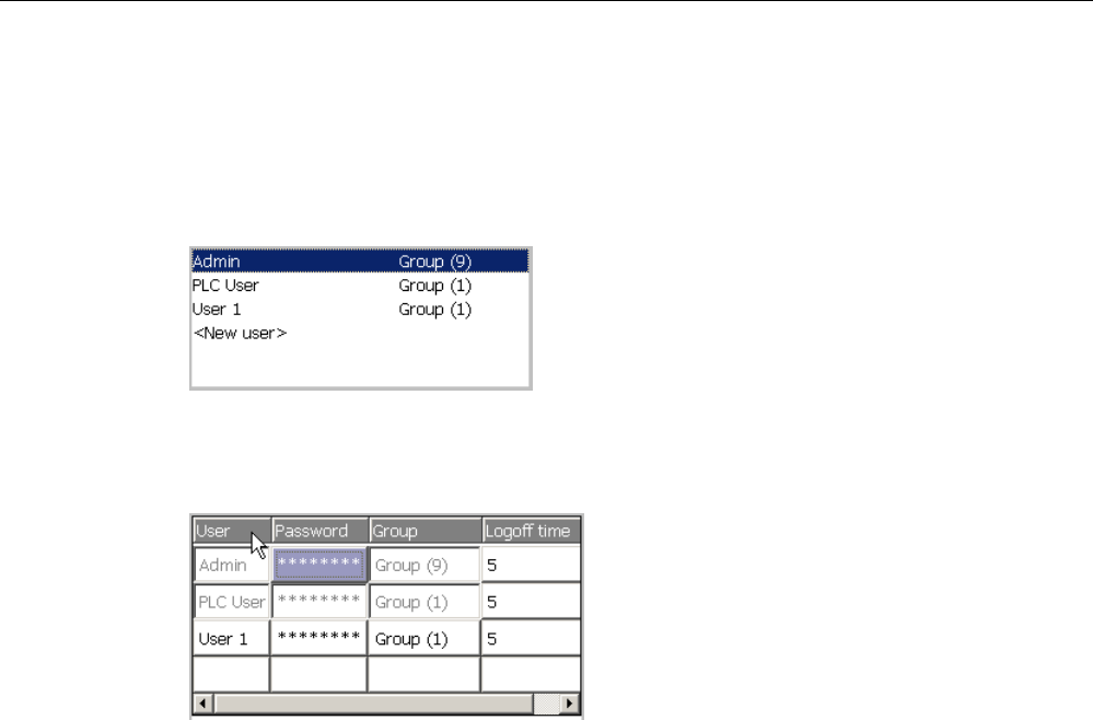
Simple user view
If you are not logged onto the HMI device, the only entry contained in the simple user view is
"<ENTER>".
If you are logged onto the HMI device, the simple user view only displays the user name and
user group.
Extended user view
The extended user view displays information about the users.
The extended user view contains the following columns:
● Users
● Password
● Group
● Logoff time
PRELIMINARY II
1.7.2010
Operating a project
11.7 Project security
Wireless Teach Pendant F IWLAN V2
230 Operating Instructions, 08/2010, A5E02453837-01
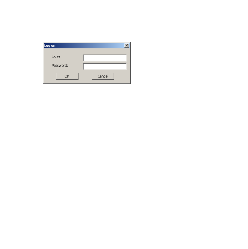
11.7.3 User logon
Use the logon dialog of the HMI device to log onto the security system. Enter your user
name and password in the logon dialog.
The logon dialog opens in the following cases:
● You press an operator control with password protection
● You press an operator control that was configured for displaying the logon dialog
● Select the "<ENTER>" entry in the simple user view
● Select a blank entry in the extended user view
● The logon dialog will be automatically displayed when the project is started, depending on
the configuration
More detailed information is available in your plant documentation.
Requirement
● The logon dialog is open.
Procedure
Proceed as follows:
1. Enter the user name and password.
Touch the corresponding text box. The alphanumerical screen keyboard is displayed.
Note
The user name is not case-sensitive.
The password is case-sensitive.
2. Select "OK" to confirm logon.
Result After successful logon to the security system, you can execute password-protected functions
on the HMI device for which you have authorizations.
If you enter a wrong password, an error message is displayed when an alarm window has
been configured.
PRELIMINARY II
1.7.2010

Operating a project
11.7 Project security
Wireless Teach Pendant F IWLAN V2
Operating Instructions, 08/2010, A5E02453837-01 231
11.7.4 User logoff
Requirement
● You have logged into the security system of the HMI device.
Procedure
You have the following options for logging off:
● Press an operator control that is configured for logging off the security system.
● If you do not operate a project and exceed the logoff time, your user account will be
locked.
Your user account will be automatically logged off if you enter an incorrect password.
Result
You are no longer logged onto the project. In order to use an operator control in the security
system, you need to log on again.
11.7.5 Creating users
You create a user with both the simple and enhanced user display.
Requirement
● A configured screen with user display is shown.
● You have user management authorization or you are the administrator.
Note
The following characters are prohibited in passwords:
Blank
Special characters * ? . % / \ ' "
Procedure – Creating a user in the simple user view
Proceed as follows:
1. Touch the "<New User>" entry in the user view.
PRELIMINARY II
1.7.2010
Operating a project
11.7 Project security
Wireless Teach Pendant F IWLAN V2
232 Operating Instructions, 08/2010, A5E02453837-01
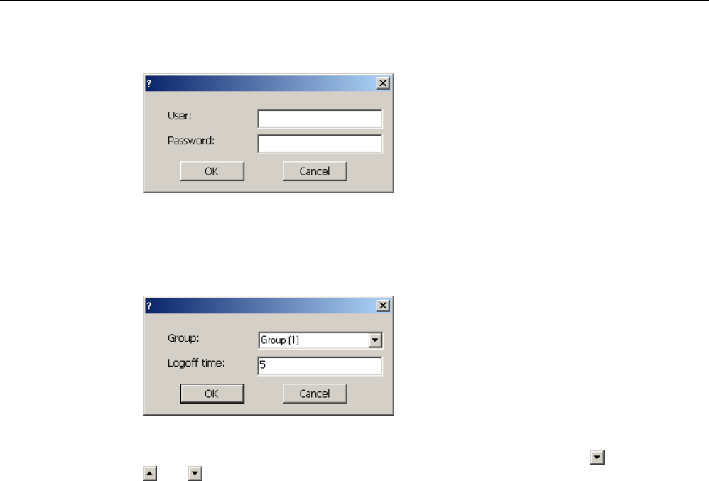
The following dialog appears:
2. Enter the desired user name and password.
Touch the corresponding text box. The alphanumerical screen keyboard is displayed.
3. Touch the "OK" button.
The following dialog appears:
4. Assign the user to a group.
In order to do so, open the "Group" drop down list box by means of the button. Select
and to scroll in the drop down list box.
5. Touch the required entry in the drop down list box.
The selected entry is then accepted as input.
6. Touch the text box "Logoff time".
The screen keyboard is displayed.
7. Enter a value between 0 and 60 for the logoff time in minutes.
The value 0 stands for "no automatic logoff."
8. Touch the "OK" button to confirm your entries.
Procedure – Creating a user in the extended user view
Proceed as follows:
1. Double-click the desired field in the blank line of the user view.
The screen keyboard is displayed.
2. Enter the respective user data in the field:
– Assign the user to one of the groups from the drop down list box.
– Enter a value between 0 and 60 for the logoff time in minutes.
The value 0 stands for "no automatic logoff."
Result The new user is created.
PRELIMINARY II
1.7.2010

Operating a project
11.7 Project security
Wireless Teach Pendant F IWLAN V2
Operating Instructions, 08/2010, A5E02453837-01 233
11.7.6 Changing user data
You have opened a screen with a user view. The data you are allowed to change depends
on your authorization:
Requirement ● You are an administrator or a user with user management authorization.
In these cases you are allowed to change the data for all the users on the HMI device in
the user view:
– User name
– Group assignment
– Password
– Logoff time
● You are a user without user management authorization.
In this case you are only allowed to change your personal user data:
– Password
– Logoff time, if configured
Note
You can only change the logoff time and password for the "Admin" user.
You can only change the logoff time for the "PLC_User". This user is used for logging
on via the PLC
Procedure
The procedure applies to simple and extended user view alike.
Proceed as follows:
1. In the user view, touch the user whose user data you want to change
2. When entering the data, use exactly the same procedure as for creating a user
Result
The user data for the user is changed.
PRELIMINARY II
1.7.2010

Operating a project
11.7 Project security
Wireless Teach Pendant F IWLAN V2
234 Operating Instructions, 08/2010, A5E02453837-01
11.7.7 Deleting users
Requirement
● You have opened a screen with a user view.
● You are an administrator or you have permission for user management.
Procedure
Note
The "Admin" and "PLC_User" users exist by default. You cannot delete these users.
1. Delete the entered user name.
Result
The affected user can no longer use the operator controls with permission.
PRELIMINARY II
1.7.2010

Operating a project
11.8 Error cases in the project operation
Wireless Teach Pendant F IWLAN V2
Operating Instructions, 08/2010, A5E02453837-01 235
11.8 Error cases in the project operation
During fail-safe operation, you must be aware that the following error cases may arise:
● Leaving an HMI device logged onto a machine
CAUTION
Shutdown possible
If the HMI device is in a state where it is constantly ready for operation, the main
rechargeable battery will lose its charge. A discharged main rechargeable battery
causes communication failure. The F-CPU initiates a shutdown.
If you do not need the HMI device:
Log off the HMI device from the machine.
Close the active project.
Switch off the HMI device or place it in the docking station.
● Internal error
If an internal error occurs on the HMI device, the "SAFE" and "RNG" LEDs go out. and
the project is terminated immediately. The HMI device displays the error code message –
see section "Diagnostics (Page 204)".
Safety functions are no longer available. Contact the SIEMENS hotline.
● Communication error
If a communication error occurs on the HMI device, the "SAFE" LED goes out. Safety
functions are no longer available. The following situations can occur with communication
errors:
– When the HMI device is logged onto a machine:
The F-CPU initiates a shutdown. The F-CPU stops the plant unit associated with the
machine.
– When the HMI device is not logged onto a machine:
The F-CPU initiates a global rampdown.
– If communication is reestablished within 60 seconds:
The EMERGENCY STOP button is enabled again. The "SAFE" LED lights up again.
Acknowledge the communication error. The "RNG" LED lights up when the HMI
device is logged onto a machine.
– If communication remains interrupted for more than 60 seconds:
The HMI device terminates the project. The "RNG" LED lights up when the HMI device
is logged on to a machine.
PRELIMINARY II
1.7.2010

Operating a project
11.9 Closing the project
Wireless Teach Pendant F IWLAN V2
236 Operating Instructions, 08/2010, A5E02453837-01
11.9 Closing the project
The procedure for closing the active project is identical to the procedure for removing the
HMI device.
See also
Removing the HMI device (Page 213)
PRELIMINARY II
1.7.2010
Wireless Teach Pendant F IWLAN V2
Operating Instructions, 08/2010, A5E02453837-01 237
Service and maintenance 12
12.1 Maintenance and care
Read sections "Safety-related operator controls (Page 88)" and "Safety instructions
(Page 72)" for information on service and maintenance.
Scope of maintenance
The HMI device is designed for maintenance-free operation. Remember to include
accessories and peripheral equipment in the maintenance.
The scope of maintenance includes:
Function test
Perform an annual function test for the enabling button and EMERGENCY STOP button.
Proceed as follows:
1. Switch on the HMI device.
2. Press both enabling buttons when the "Test Enabling Button" dialog is shown.
3. Press the EMERGENCY STOP button.
Storing the main rechargeable battery
A lithium-ion rechargeable battery loses more than 50% of its charge capacity within three
years .
Store rechargeable batteries at 40 to 60% of their capacity to ensure optimal service life.
Manufacturers recommend storage at 15° C – which is optimal for aging and self-discharge.
Charge the battery every six months to 40 to 60% of its charge capacity.
Scope of maintenance
The scope of maintenance includes:
● Cleaning the touch screen
● Cleaning the membrane keypad
PRELIMINARY II
1.7.2010
Service and maintenance
12.2 Replacing the rechargeable buffer battery
Wireless Teach Pendant F IWLAN V2
238 Operating Instructions, 08/2010, A5E02453837-01
Procedure
CAUTION
Damage possible
The use of compressed air, steam cleaners or aggressive solutions or scouring agents will
damage the HMI device.
Use a cleaning cloth dampened with a cleaning agent to clean the equipment. Only use
water with a little liquid soap or a screen cleaning solution.
Proceed as follows:
1. Switch off the HMI device.
2. Spray the cleaning solution onto a cleaning cloth.
Do not spray directly onto the HMI device.
3. Clean the HMI device.
When cleaning the display, wipe inwards from the edge of screen.
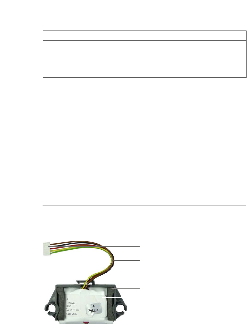
12.2 Replacing the rechargeable buffer battery
The capacity of the rechargeable buffer battery is reduced by age. After about five years, the
rechargeable buffer battery needs to be replaced. This section describes how to replace the
rechargeable buffer battery.
Procedure
Note
Read sections "Safety instructions (Page 66)", "Opening and closing the terminal
compartment (Page 67)" and "Safety instructions (Page 72)".
&RQQHFWLQJFDEOH
(QFORVXUH
5HFKDUJHDEOHEXIIHUEDWWHU\
&RQQHFWRUV
PRELIMINARY II
1.7.2010
Service and maintenance
12.3 Spare parts and repairs
Wireless Teach Pendant F IWLAN V2
Operating Instructions, 08/2010, A5E02453837-01 239
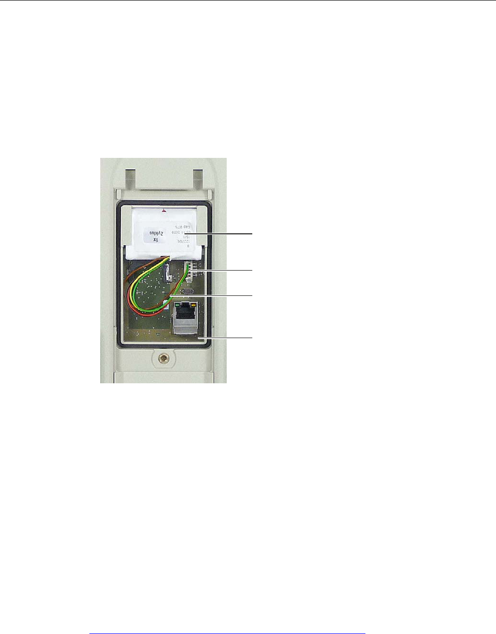
Proceed as follows:
1. Remove the enclosure.
The enclosure is not needed for installation.
2. Open the connection compartment.
3. Pull out the connector.
4. Slide the rechargeable buffer battery out of the guide and put it down.
5. Insert the new rechargeable buffer battery, as shown in the following illustration.
5HFKDUJHDEOHEXIIHUEDWWHU\
&RQQHFWLQJFDEOH
3OXJDQGVRFNHW
3ULQWHGFLUFXLWERDUG
6. Connect the plug.
7. Position the cable so that it cannot be pinched when you close the connection
compartment.
8. Close the connection compartment.
12.3 Spare parts and repairs
If the unit needs to be repaired, ship the HMI device to the Return Center in Fürth.
The address is:
Siemens AG
Industry Sector
Returns Center
Siemensstr. 2
90766 Fürth
Germany
You can find more detailed information on the Internet at Spare parts and repairs
(http://support.automation.siemens.com/WW/view/en/16611927).
PRELIMINARY II
1.7.2010

Service and maintenance
12.3 Spare parts and repairs
Wireless Teach Pendant F IWLAN V2
240 Operating Instructions, 08/2010, A5E02453837-01
PRELIMINARY II
1.7.2010
Wireless Teach Pendant F IWLAN V2
Operating Instructions, 08/2010, A5E02453837-01 241
Technical specifications 13
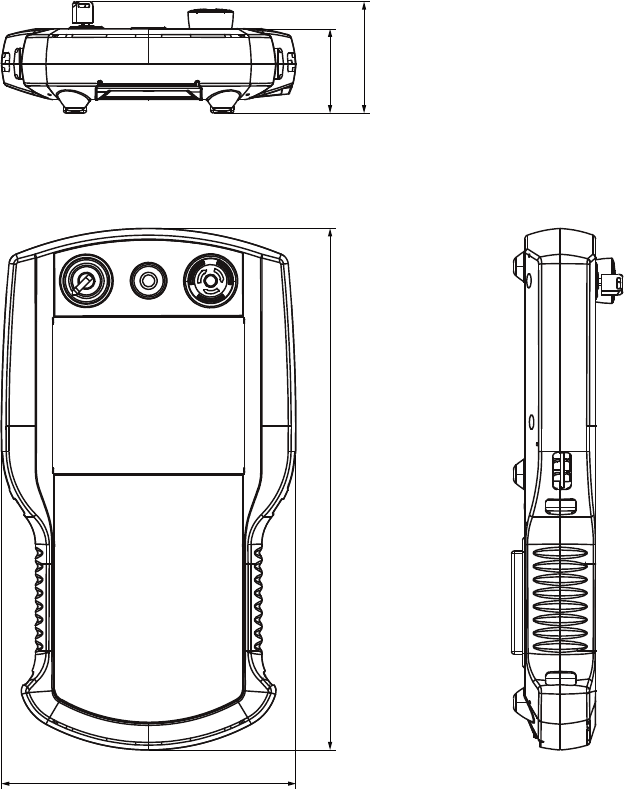
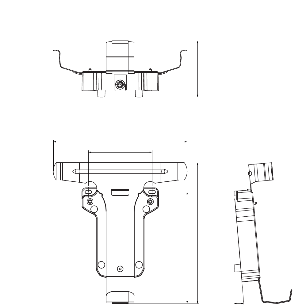
13.1 Dimension drawings
13.1.1 Wireless Teach Pendant F IWLAN
s
s
s
s
$OOGLPHQVLRQVLQPP
PRELIMINARY II
1.7.2010
Technical specifications
13.1 Dimension drawings
Wireless Teach Pendant F IWLAN V2
242 Operating Instructions, 08/2010, A5E02453837-01
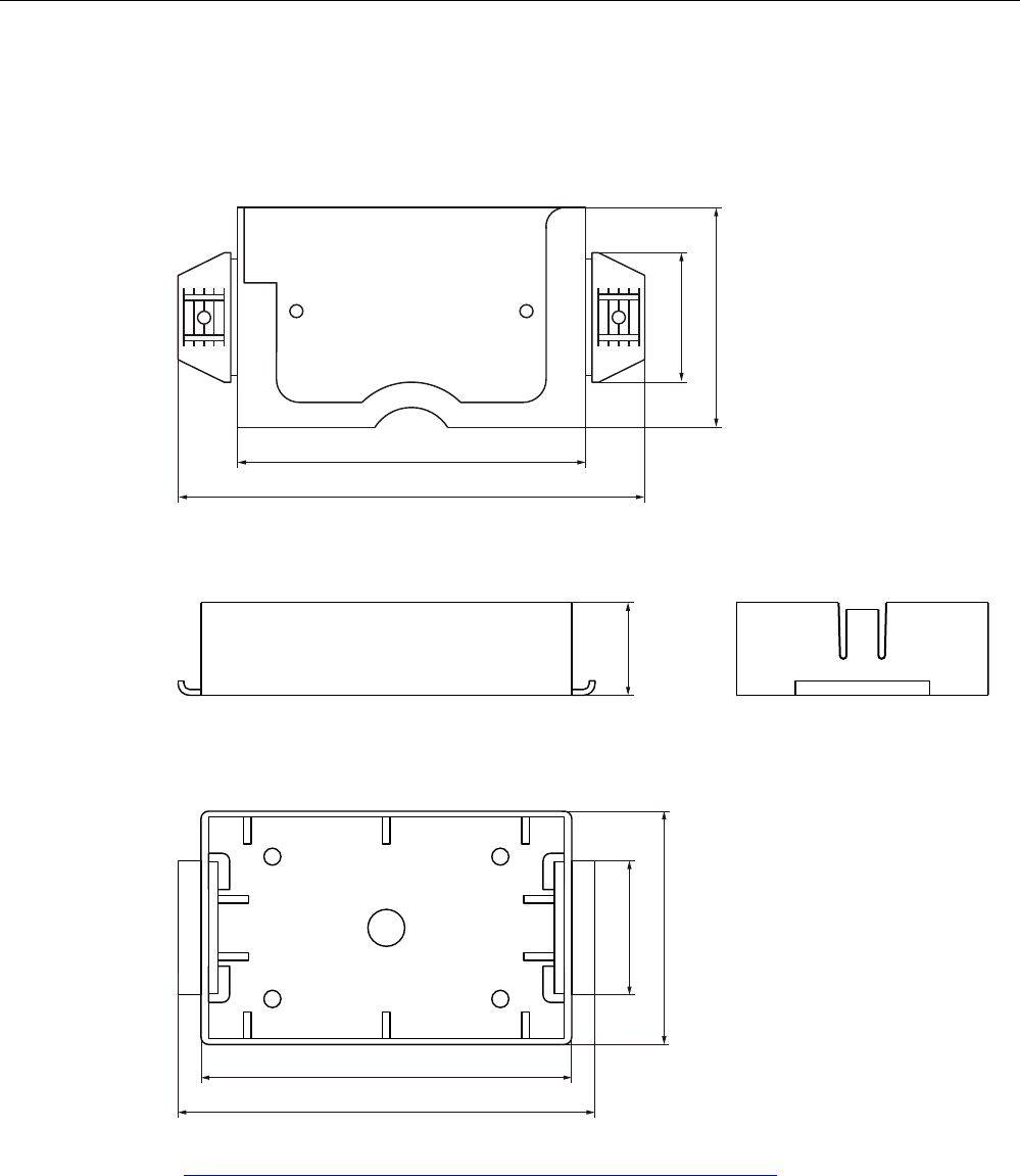
13.1.2 Docking station
r
$OOGLPHQVLRQVLQPP
PRELIMINARY II
1.7.2010
Technical specifications
13.1 Dimension drawings
Wireless Teach Pendant F IWLAN V2
Operating Instructions, 08/2010, A5E02453837-01 243
13.1.3 RFID tag
Fixing pocket
$OOGLPHQVLRQVLQPP
Spacer
$OOH$QJDEHQLQPP
You can additional illustrations on the Internet at Image database
(http://www.automation.siemens.com/bilddb/index.aspx?att14s=35).
PRELIMINARY II
1.7.2010
Technical specifications
13.2 Specifications
Wireless Teach Pendant F IWLAN V2
244 Operating Instructions, 08/2010, A5E02453837-01
13.2 Specifications
13.2.1 Wireless Teach Pendant F IWLAN V2
General information
Weight with battery, without packaging Approx. 2 kg
Drop height with main rechargeable battery, max. 0.5 m
Buffer time of internal clock with battery inserted Approx. 4 days
Display
Type Color TFT LC display
Display area, active 132.5 mm x 99.5 mm
Resolution 640 x 480 pixels
Colors, displayable 65536 colors
Brightness control Yes
Backlighting
Half Brightness Life Time, typical
CCFL
50000 h
Pixel error class according to DIN EN ISO 13406-
2
II
Input unit
Touch screen Analog, resistive
Membrane keyboard 1
Rotary switch 1, with 2 positions
Illuminated pushbutton 1
EMERGENCY STOP button 1
Enabling button 2
Memory
Application memory 6 MB
SD memory card 2 GB
PRELIMINARY II
1.7.2010

Technical specifications
13.2 Specifications
Wireless Teach Pendant F IWLAN V2
Operating Instructions, 08/2010, A5E02453837-01 245
Ports
2 x USB USB host; conforms to USB standard 1.1
Supports low-speed and full-speed USB
devices.
Current load per port, max. 100 mA
1 x WLAN For PROFINET WLAN
1 x RJ45 For LAN
WLAN antenna
Antenna type Dual port patch antenna
Polarization Vertical and horizontal
Antenna gain in principle ray direction, max. 2 dBi
Impedance 50 Ω
Fail-safe operation
Note
The safety characteristics in the specifications apply for a proof-test interval of 10 years and
a mean repair time of 8 hours.
In accordance with IEC 61508
Hardware architecture Redundant 1oo2
Hardware error tolerance 1
Safe failure fraction 99.5 %
Diagnostic test interval 10 ms
Request rate High demand mode
High demand
(PFH – probability of a dangerous failure per
hour)
8.60e–11h–1
Safety class, maximum achievable (SIL) 3
Useful life 10 years
According to ISO 13849-1
Mean time to failure (MTTFd) 1516 years
Meantime to Restoration (MTTR) 8 h
Diagnostic coverage 99 %
Performance level e
Safety category 4
PRELIMINARY II
1.7.2010
Technical specifications
13.2 Specifications
Wireless Teach Pendant F IWLAN V2
246 Operating Instructions, 08/2010, A5E02453837-01
Other safety-related characteristic values
Acknowledgement time 40 ms
Response time with no fault, max. 25 ms
Discrepancy time – EMERGENCY STOP 500 ms
Discrepancy time – enabling button
"Enabling" position
"Panic" position
2 sec
1 sec
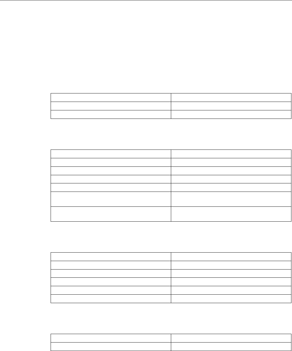
13.2.2 Interface description
USB
The figure below shows the pin assignment of the USB interface.
Pin Assignment
1 +5 VDC, out (max. 100 mA)
2 USB-DN
3 USB-DP
4 GND
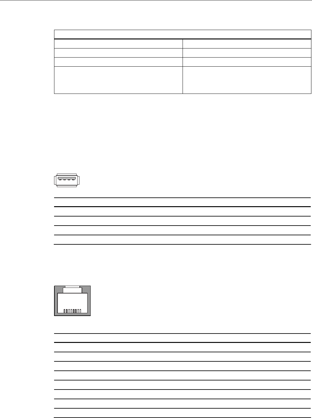
RJ45
The figure below shows the pin assignment of the RJ45 interface.
Pin Assignment
1 TD+
2 TD–
3 RD+
4 n. c.
5 n. c.
6 RD–
7 ICD+
8 ICD–
PRELIMINARY II
1.7.2010

Technical specifications
13.2 Specifications
Wireless Teach Pendant F IWLAN V2
Operating Instructions, 08/2010, A5E02453837-01 247
WLAN
Operation of a wireless interface in the frequency bands 2.4 GHz and 5 GHz. The wireless
interface is compatible with the following standards:
● IEEE 802.11a
● IEEE 802.11h
● IEEE 802.11b
● IEEE 802.11g
Receiver sensitivity
WLAN standard Data transfer rate Receiver sensitivity
IEEE 802.11a/h 54 Mbps
48 Mbps
36 Mbps
24 Mbps
18 Mbps
12 Mbps
9 Mbps
6 Mbps
-74 dBm
-75 dBm
-80 dBm
-83 dBm
-86 dBm
-88 dBm
-89 dBm
-90 dBm
IEEE 802.11g 54 Mbps
48 Mbps
36 Mbps
24 Mbps
18 Mbps
12 Mbps
9 Mbps
6 Mbps
-76 dBm
-77 dBm
-82 dBm
-85 dBm
-88 dBm
-91 dBm
-92 dBm
-93 dBm
IEEE 802.11b 11 Mbps
5.5 Mbps
2 Mbps
1 Mbps
-90 dBm
-92 dBm
-94 dBm
-98 dBm
PRELIMINARY II
1.7.2010

Technical specifications
13.2 Specifications
Wireless Teach Pendant F IWLAN V2
248 Operating Instructions, 08/2010, A5E02453837-01
Transmission power
WLAN standard Data transfer rate Receiver sensitivity
IEEE 802.11a/h
(5.18 ∼ 5.7 GHz)
54 Mbps
48 Mbps
36 Mbps
6-24 Mbps
13.5 dBm
15 dBm
16 dBm
17 dBm
IEEE 802.11a/h
(4.92 ∼ 5.16 GHz)
(5.745 ∼ 5.825 GHz)
54 Mbps
48 Mbps
36 Mbps
6-24 Mbps
11.5 dBm
13 dBm
14 dBm
15 dBm
IEEE 802.11g
(2.412 ∼ 2.484 GHz)
54 Mbps
48 Mbps
36 Mbps
6-24 Mbps
16 dBm
17 dBm
17 dBm
17 dBm
IEEE 802.11b 11 Mbps
5.5 Mbps
2 Mbps
1 Mbps
20 dBm
20 dBm
20 dBm
20 dBm
13.2.3 Rechargeable batteries
Main rechargeable battery
Type Lithium ion accumulator
Operation time in normal mode Approx. 4 h
Operation time in stand-by mode Approx. 15 days
Charging cycles 500
Charging time Approx. 4 h 1)
Rechargeable buffer battery
Type Lithium ion accumulator
Bridging time 20 sec
Charging cycles 500
1) See section Charging the main rechargeable battery (Page 75),
Maintenance and care (Page 237)
PRELIMINARY II
1.7.2010

Technical specifications
13.2 Specifications
Wireless Teach Pendant F IWLAN V2
Operating Instructions, 08/2010, A5E02453837-01 249
13.2.4 Docking station
Weight without packing Approx. 1.1 kg
Power supply
Nominal voltage +24 VDC via external power supply
Transients, maximum permitted 35 V (500 ms)
Time between two transients, minimum 50 s
Power consumption with Wireless Teach Pendant F
IWLAN
Typical
Constant current, maximum
Power on current surge I2t
Approx. 1.5 A
Approx. 1.8 A
Approx. 1.7 A2s
Fuse, internal Electronic
13.2.5 Charger
Weight without packing Approx. 1.1 kg
Power supply
Nominal voltage +24 VDC via external power supply unit
Transients, maximum permitted 35 V (500 ms)
Time between two transients, minimum 50 sec
Power consumption with Wireless Teach Pendant F
IWLAN
Typical
Constant current, maximum
Power on current surge I2t
Approx. 1.5 A
Approx. 1.8 A
Approx. 1.7 A2s
Fuse, internal Electronic
PRELIMINARY II
1.7.2010
Technical specifications
13.2 Specifications
Wireless Teach Pendant F IWLAN V2
250 Operating Instructions, 08/2010, A5E02453837-01
13.2.6 RFID tag
Memory capacity 128 bytes
Memory technology EEPROM
Protocol ISO 15693
Data retention, at +40° C 10 years
MTBF, at + 40° C 2 x 10⁶ hours
Read cycles Unlimited
Write cycles, typical 200000
Write cycles, minimal 100000
Multitag-capable Yes
Energy supply, inductive Energy transfer (without battery)
Degree of protection in accordance with EN
60529
IP68
Mechanical design
Material PC
Color White/petrol
Dimensions (L x W x H) in mm 85.6 x 54 x 0.9
Ambient temperature
Operation –25° C to +80° C
Storage/transport –25° C to +80° C
13.2.7 F-FBs and configuration
F-FBs required in safety program
F_FB_MP 1 per Wireless Teach Pendant F IWLAN, maximum 126
F_FB_RNG_4 1 per effective range, for which up to 4 HMI devices have logon
permission
F_FB_RNG_16 1 per effective range, for which up to 16 HMI devices have logon
permission
DB_STATES 1
Configuration
Number of effective ranges in a project, max. 127
Number of RFID tags in a project, max. 127
Number of RDIF tags per effective range, max. 127
Number of HMI devices authorized for logon per
effective range, max.
With F_FB_RNG_4: 4
With F_FB_RNG_16: 16
PRELIMINARY II
1.7.2010
Wireless Teach Pendant F IWLAN V2
Operating Instructions, 08/2010, A5E02453837-01 251
Appendix A
A.1 ESD guideline
What does ESD mean?
An electronic module is equipped with highly integrated electronic components. Due to their
design, electronic components are highly sensitive to overvoltage and thus to the discharge
of static electricity. Such electronic components are labeled as electrostatic sensitive devices
(ESD).
The following abbreviations are commonly used for electrostatic sensitive devices:
● ESD – Electrostatic Sensitive Device
● ESD – Electrostatic Sensitive Device (internationally recognized term)
Electrostatic charge
CAUTION
Electrostatic charge
ESDs may be destroyed by voltages far below the level perceived by human beings. If you
are not discharged electrostatically, the voltage that you transfer when touching a
component or the contact points of a module can already cause damage.
The damage to an ESD caused by overvoltage is usually not recognized immediately. The
damage only becomes apparent after a long period of operation.
Discharge any electrostatic charge of your body before you touch the ESD.
Anyone who is not connected conductively to their surroundings is subject to electrostatic
charge.
PRELIMINARY II
1.7.2010
Appendix
A.1 ESD guideline
Wireless Teach Pendant F IWLAN V2
252 Operating Instructions, 08/2010, A5E02453837-01
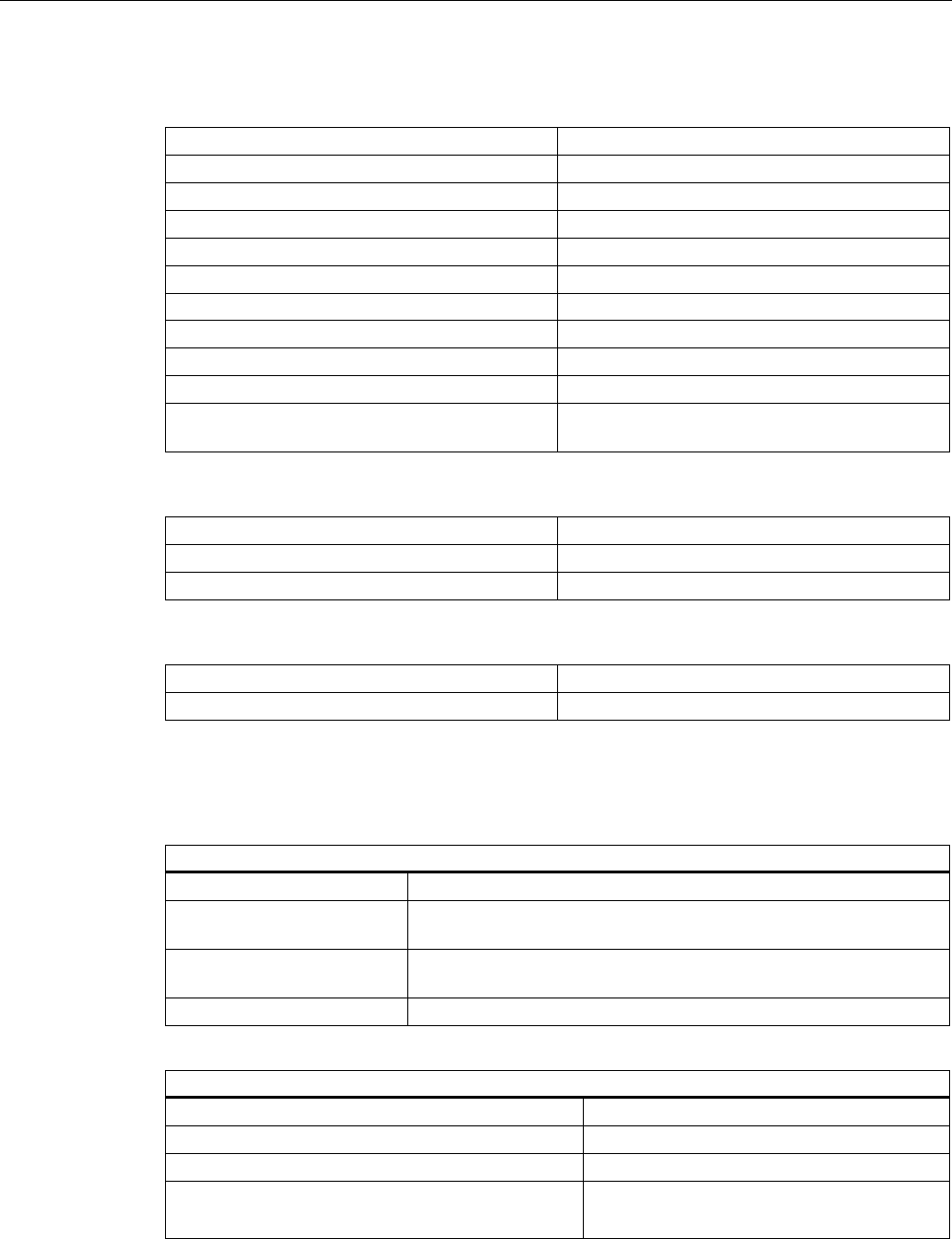
The following diagram shows the maximum voltage values to which a person can be
charged electrostatically. The values depend on the material and humidity. The shown
values are in conformity with the specifications of EN 61000-4-2.
9ROWDJH
5HODWLYHKXPLGLW\
>@
>N9@
① Synthetic materials
② Wool
③ Antistatic materials such as wood or concrete
Protective measures against discharge of static electricity
CAUTION
Grounding measures
There is no equipotential bonding without grounding. An electrostatic charge is not
discharged and may damage the ESD.
When working with electrostatic sensitive devices, make sure that the person and the
workplace are properly grounded.
Note the following:
● Only touch the ESD if it is absolutely necessary.
● When you touch ESD modules, avoid touching the pins or the PCB tracks.
This precaution reduces the risk of damaging an ESD.
● Discharge electrostatic electricity from your body if you are performing measurements on
an ESD.
To do so, touch a grounded metal object before you carry out the measurement.
● Always use grounded measuring instruments.
PRELIMINARY II
1.7.2010
Appendix
A.2 Typical operating procedures and potential fault scenarios
Wireless Teach Pendant F IWLAN V2
Operating Instructions, 08/2010, A5E02453837-01 253
A.2 Typical operating procedures and potential fault scenarios
A.2.1 Overview
This section describes typical application cases for the HMI device. The following states are
graphically represented in the application cases.
● LED status
● Operability of the EMERGENCY STOP button and enabling buttons
The used icons have the following meaning:
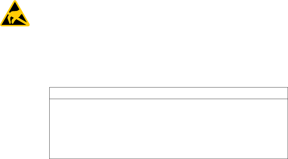
● LED display
Icon Meaning
6$)( 3:5 &20 51* %$7
Status of the LEDs that are displayed
on the HMI device during the
described situation.
All LEDs are on.
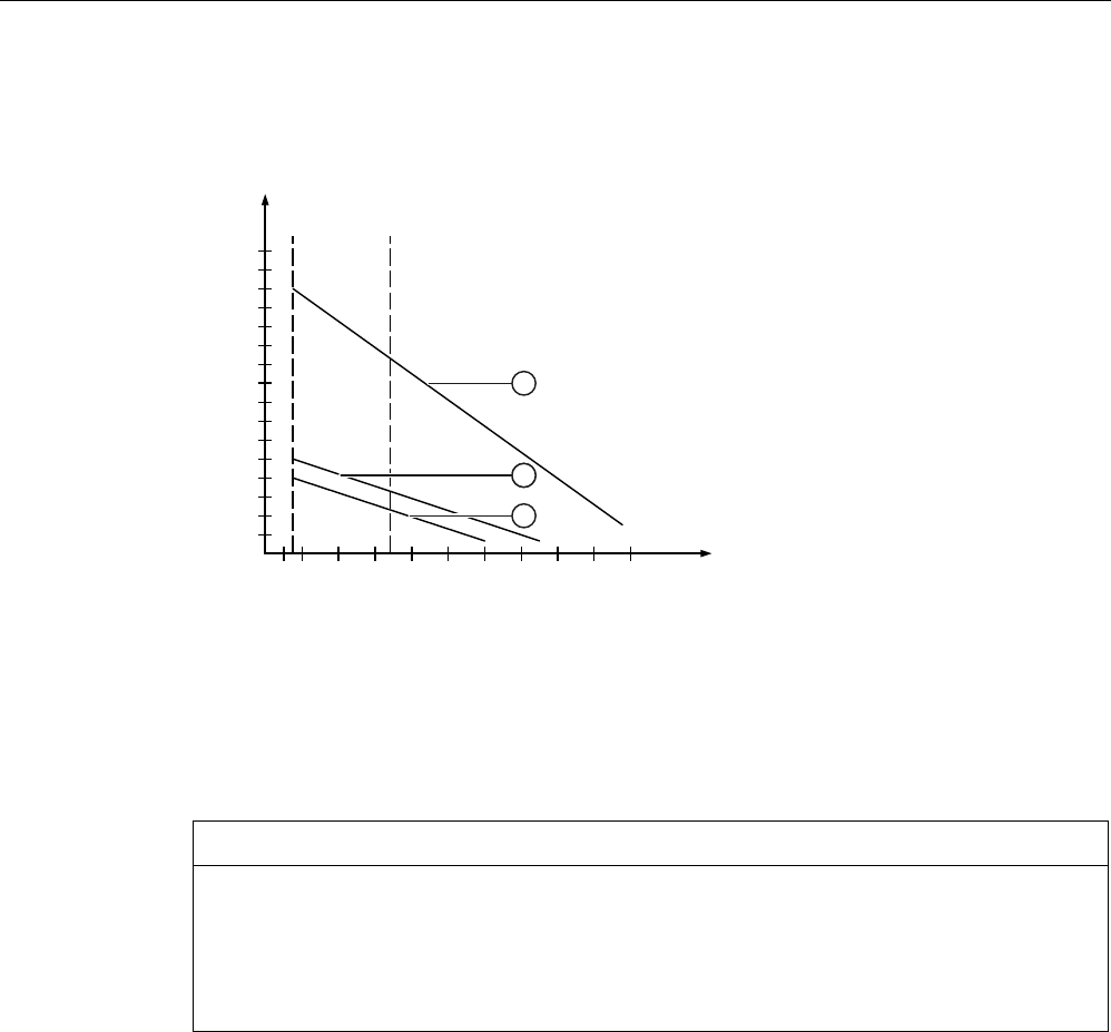
● EMERGENCY STOP button
Icon Meaning
Pressing the EMERGENCY STOP button triggers an EMERGENCY STOP.
Pressing the EMERGENCY STOP has no effect.
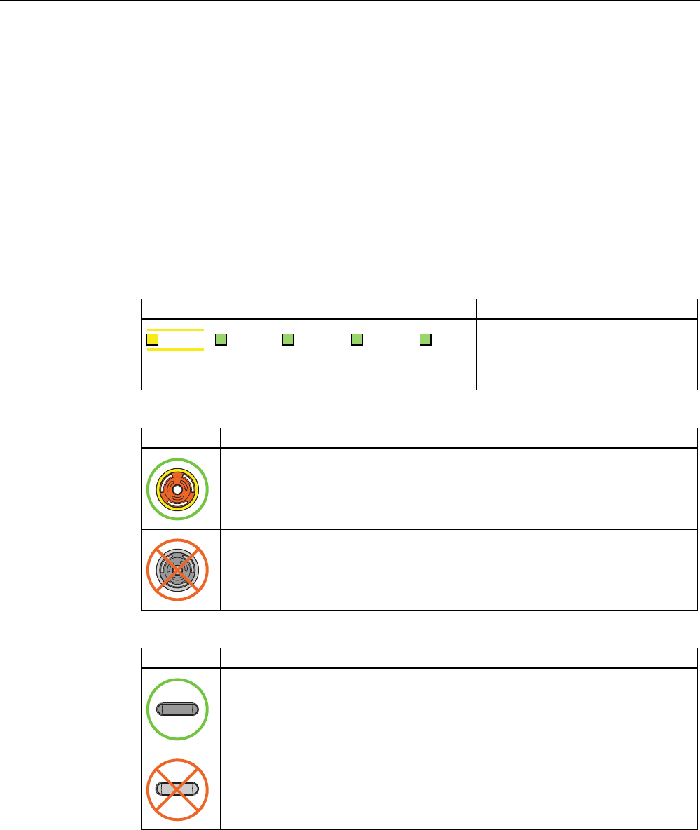
● Enabling button
Icon Meaning
The operator can release movements of the assigned machine with the enabling
buttons.
Pressing the enabling buttons has no effect.
PRELIMINARY II
1.7.2010
Appendix
A.2 Typical operating procedures and potential fault scenarios
Wireless Teach Pendant F IWLAN V2
254 Operating Instructions, 08/2010, A5E02453837-01
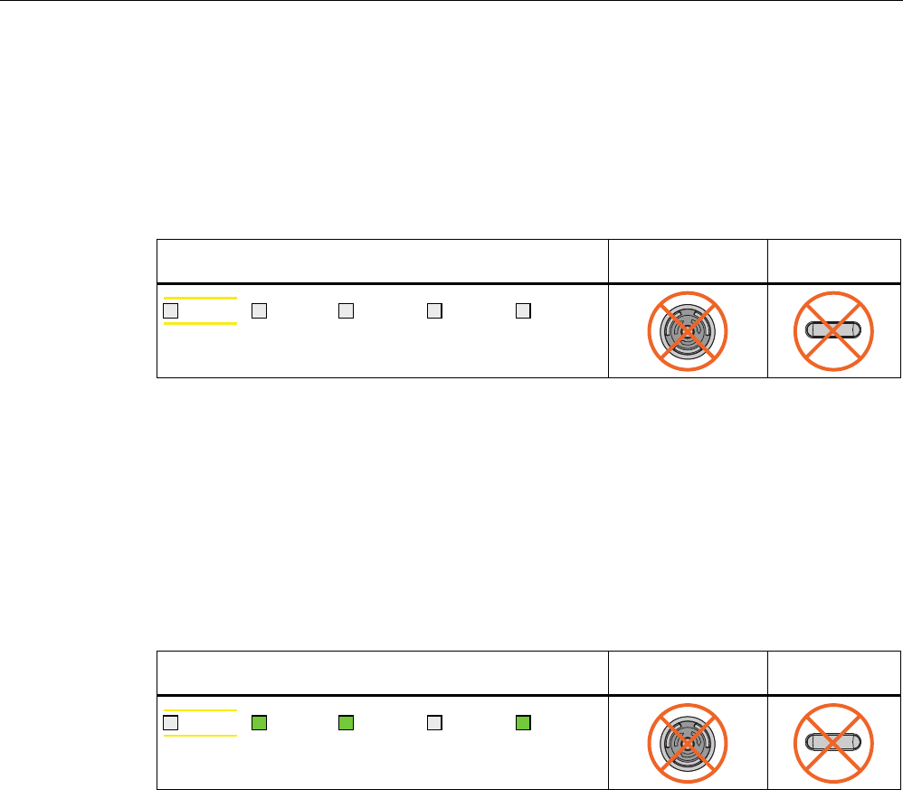
A.2.2 Switch on the HMI device.
Requirement
● The HMI device is switched off.
● The rechargeable battery is fully charged.
LED display EMERGENCY
STOP button
Enabling button
6$)( 3:5 &20 51* %$7
Procedure 1. Switch on the HMI device using the ON/OFF button.
Communication via WLAN starts up. While the WLAN connection is being established the
"COM" LED flashes.
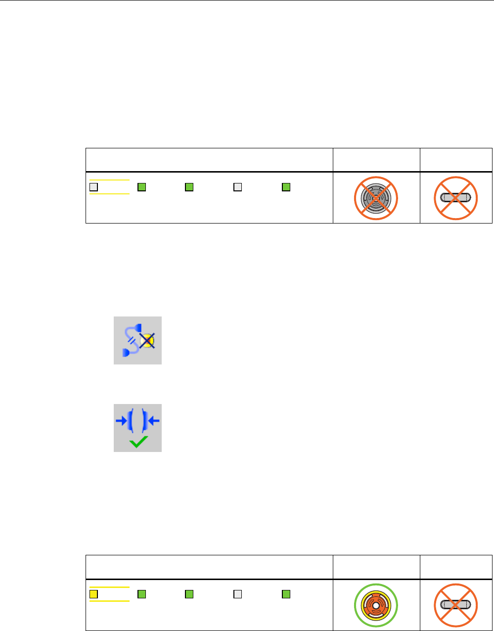
Result ● WLAN communication is established.
● The HMI device displays the Windows CE Desktop with the Loader.
LED display EMERGENCY
STOP button
Enabling button
6$)( 3:5 &20 51* %$7
PRELIMINARY II
1.7.2010
Appendix
A.2 Typical operating procedures and potential fault scenarios
Wireless Teach Pendant F IWLAN V2
Operating Instructions, 08/2010, A5E02453837-01 255
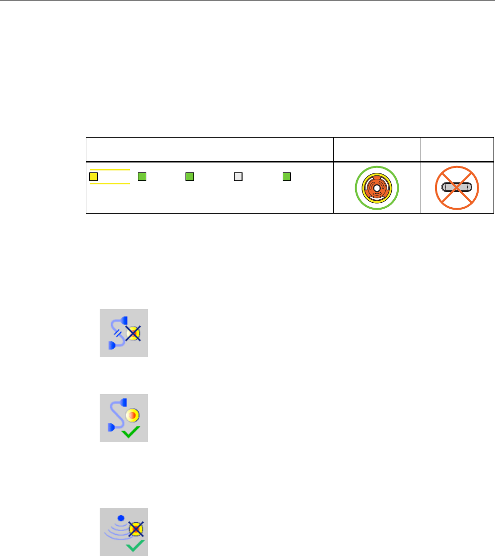
A.2.3 Integrating the HMI device
Requirement ● The HMI device is switched on.
● WLAN communication is established.
● The HMI device shows the Windows CE Desktop with the Loader.
LED display EMERGENCY
STOP button
Enabling button
6$)( 3:5 &20 51* %$7
Procedure
1. Start the project.
– PROFIsafe communication is established.
– The "Establishment of safety connection" dialog is shown with the following icon.
– The HMI device is integrated in the safety program of the F CPU.
– The "Test enabling button" dialog opens with the following icon.
2. Press both enabling buttons when prompted until the "Panic" switch position is reached.
Result
● Both enabling buttons have been tested in the "Enable" and "Panic" switch positions.
● The project start screen appears.
LED display EMERGENCY
STOP button
Enabling button
6$)( 3:5 &20 51* %$7
PRELIMINARY II
1.7.2010
Appendix
A.2 Typical operating procedures and potential fault scenarios
Wireless Teach Pendant F IWLAN V2
256 Operating Instructions, 08/2010, A5E02453837-01
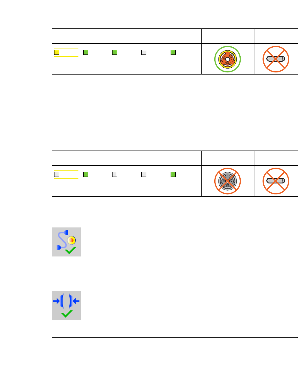
A.2.4 Communication error for the integrated HMI device
Requirement
● The HMI device is integrated in the safety program of the F-CPU.
● The HMI device is not logged onto a machine.
LED display EMERGENCY
STOP button
Enabling button
6$)( 3:5 &20 51* %$7
Procedure
1. You are leaving the WLAN range with the HMI device.
The "COM" LED flashes. The F CPU detects a communication error and initiates a global
rampdown. The "SAFE" LED goes out. The user is informed that no safety functions are
available. The "No safety connection" dialog is shown with the following symbol.
2. You will return to the WLAN range within 60 seconds.
The "Acknowledgment of communication error" dialog opens with the following symbol.
3. Acknowledge the communication error. See Result 1.
4. You remain outside the WLAN.
The "Confirm removal" dialog will be displayed after 60 seconds with the following
symbol.
See Result 2.
Result 1 – Return to the WLAN range
● The "Global rampdown" signal is canceled. PROFIsafe communication is again possible.
● The HMI device is fully operable.
PRELIMINARY II
1.7.2010
Appendix
A.2 Typical operating procedures and potential fault scenarios
Wireless Teach Pendant F IWLAN V2
Operating Instructions, 08/2010, A5E02453837-01 257
LED display EMERGENCY
STOP button
Enabling button
6$)( 3:5 &20 51* %$7
Result 2 – No return to the WLAN range
● The project will be closed immediately if you confirm the Confirm removal dialog within 60
seconds.
● The active project will be closed automatically if you do not confirm the "Confirm removal"
dialog within 60 seconds.
● The Windows CE desktop with the loader is shown on the display.
LED display EMERGENCY
STOP button
Enabling button
6$)( 3:5 &20 51* %$7
Wireless network communication is reestablished if you later return to the WLAN range with
the HMI device. Start the project again. Acknowledge the communication error in the
"Acknowledgment of communication error" dialog with the following symbol.
The "Global rampdown" signal is cancelled when you acknowledge the communication error.
Test the enabling buttons when the "Test Enabling Button" dialog is shown with the following
symbol.
The HMI device is integrated again.
Note
Users can react to a fault on the HMI device by resetting the associated F_FB_MP to the
"original state" using input "S7_MP_RES." This action sets the relevant HMI device to the
"removed" state and the global rampdown signal is canceled.
PRELIMINARY II
1.7.2010
Appendix
A.2 Typical operating procedures and potential fault scenarios
Wireless Teach Pendant F IWLAN V2
258 Operating Instructions, 08/2010, A5E02453837-01
A.2.5 Discrepancy error during enabling
The enabling button is two-channel. Both contacts must be closed at the same time to reach
the enabled state. A discrepancy error is generated if one of the contacts is open while the
other is closed. The following fault scenarios can occur:
● The enabling button is askew
● The enabling button is defective.
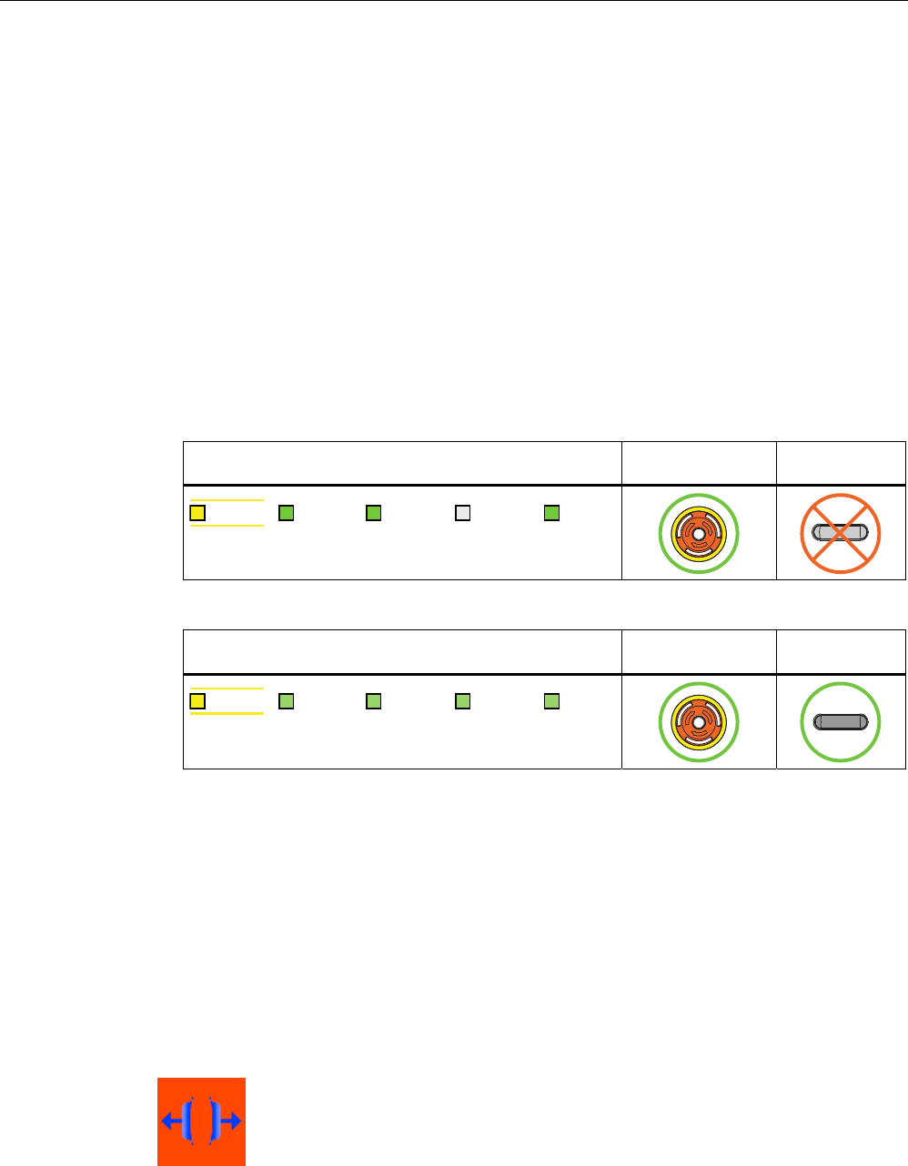
A.2.5.1 The enabling button is askew
Requirement
The HMI device is integrated.
● The HMI device is not logged onto a machine.
LED display EMERGENCY
STOP button
Enabling button
6$)( 3:5 &20 51* %$7
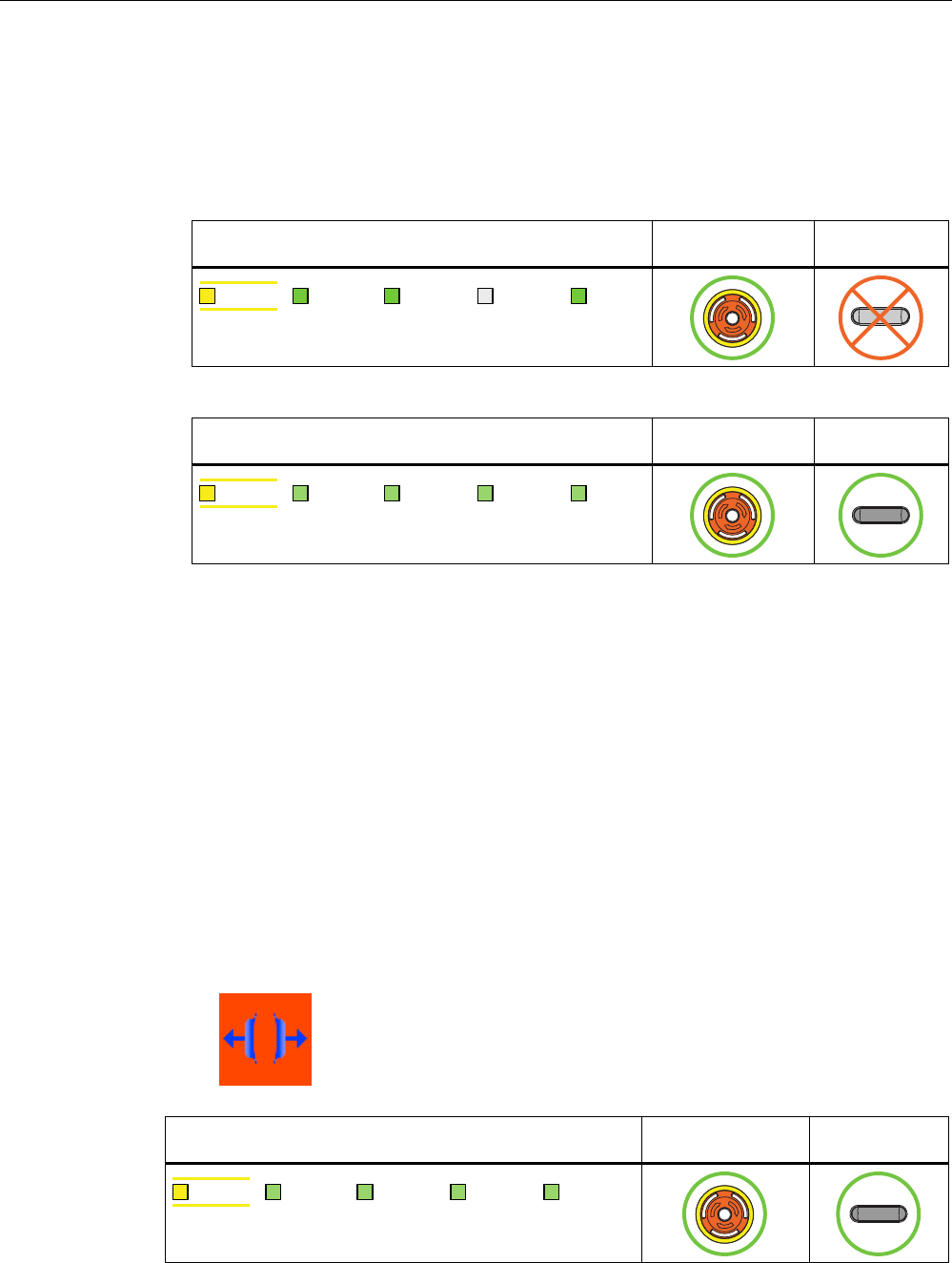
● The HMI device is logged on to a machine.
LED display EMERGENCY
STOP button
Enabling button
6$)( 3:5 &20 51* %$7
Procedure
1. Press the enabling button.
If you press the edge of an enabling button, the pressure point for the contacts is not
centered. The signal is therefore transmitted only through one of the two contacts. The
controller detects a discrepancy.
Result
The enabled state is withdrawn when a discrepancy is detected. The "Discrepancy error
enabling button" dialog opens with the following symbol when the discrepancy time expires.
PRELIMINARY II
1.7.2010
Appendix
A.2 Typical operating procedures and potential fault scenarios
Wireless Teach Pendant F IWLAN V2
Operating Instructions, 08/2010, A5E02453837-01 259
The dialog stays open until this discrepancy is corrected. Additional information on
discrepancy time is available in "Wireless Teach Pendant F IWLAN V2 (Page 244)", section
"Fail-safe operation".
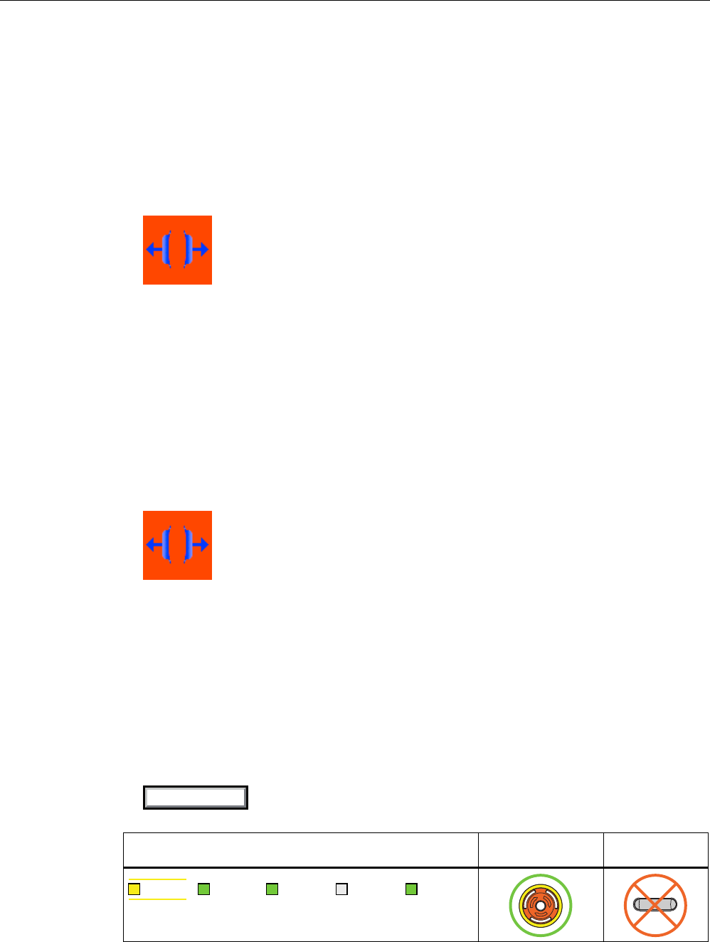
Enabling is made possible by pressing the enabling button again from the zero position.
● The HMI device is integrated but not logged onto a machine.
LED display EMERGENCY
STOP button
Enabling button
6$)( 3:5 &20 51* %$7
● The HMI device is integrated and logged onto a machine:
LED display EMERGENCY
STOP button
Enabling button
6$)( 3:5 &20 51* %$7
A.2.5.2 The enabling button is defective.
Requirement
● The HMI device is integrated and logged onto a machine.
● An enabling button is defective and not pressed.
Distinguish between the two scenarios:
– Scenario 1
One channel of the enabling button is opened permanently.
– Scenario 2
One channel of the enabling button is closed permanently.
Discrepancy is detected in this situation. The "Discrepancy error enabling button"
dialog is displayed with the following symbol.
LED display EMERGENCY
STOP button
Enabling button
6$)( 3:5 &20 51* %$7
PRELIMINARY II
1.7.2010
Appendix
A.2 Typical operating procedures and potential fault scenarios
Wireless Teach Pendant F IWLAN V2
260 Operating Instructions, 08/2010, A5E02453837-01
Procedure
1. Press the enabling button.
Result – Scenario 1
● The enabled state is not activated.
The "Discrepancy error enabling button" dialog opens with the following symbol when the
discrepancy time expires.
The dialog stays open until the enabling button is released. This step cancels the
discrepancy. A discrepancy error is displayed again when the operator presses the
enabling button once again .
● The device must be repaired. See section "Spare parts and repairs (Page 239)".
● Press the second working enabling button to remove the HMI device.
Result – Scenario 2
● The "Discrepancy error enabling button" dialog is closed and the discrepancy is cleared.
The enable signal remains in deactivated state. The "Discrepancy error enabling button"
dialog is displayed with the following symbol when the enabling button is released.
● The device must be repaired. See section "Spare parts and repairs (Page 239)".
A.2.6 Logging onto a machine
Requirement
● You have the HMI device at a distance of no more than 5 cm in front of an RFID tag.
● The "Effective range name (RFID)" object is shown in white labeled "Scan".
6FDQ
LED display EMERGENCY
STOP button
Enabling button
6$)( 3:5 &20 51* %$7
PRELIMINARY II
1.7.2010
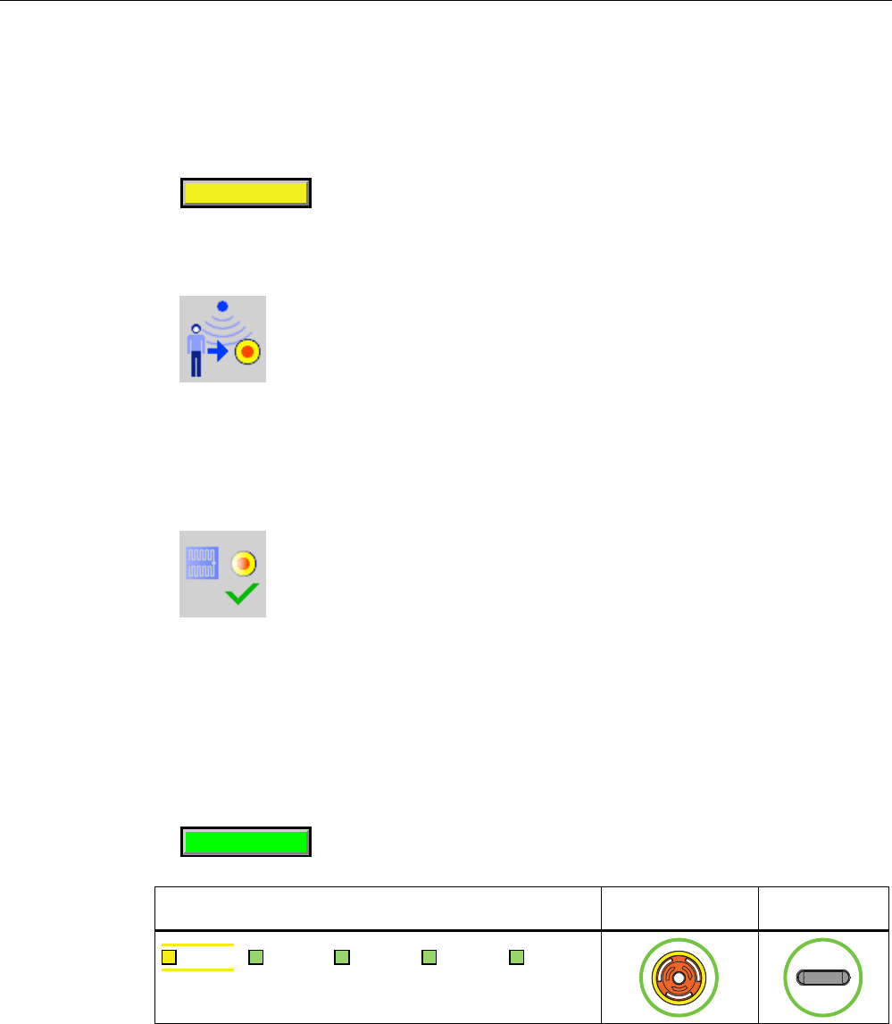
Appendix
A.2 Typical operating procedures and potential fault scenarios
Wireless Teach Pendant F IWLAN V2
Operating Instructions, 08/2010, A5E02453837-01 261
Procedure
1. Touch the "Effective range name (RFID)" object labeled "Scan".
The HMI device searches for RFID tags, the "Effective range name (RFID)" object is
shown in yellow labeled "Scanning".
6FDQQLQJ
If the "Effective range name (RFID)" object is configured with password protection, enter
a valid user name and a valid password.
The "Effective range logon" dialog opens with the following symbol.
2. Read the effective range ID from the RFID tag.
3. Enter the effective range ID.
4. Click "Yes".
The dialog closes. The "Confirmation of logon" dialog is displayed with the following
symbol.
5. Confirm the logon to the RFID tag with the enabling button.
Result
● You have logged on the HMI device to the machine via the RFID tag.
● The "Effective range name (RFID)" operator control is shown in green and labeled with
the name of the effective range. The following figure shows the "Effective range name
(RFID)" object after logon to an effective range with the name "Robot 1".
5RERW
LED display EMERGENCY
STOP button
Enabling button
6$)( 3:5 &20 51* %$7
PRELIMINARY II
1.7.2010
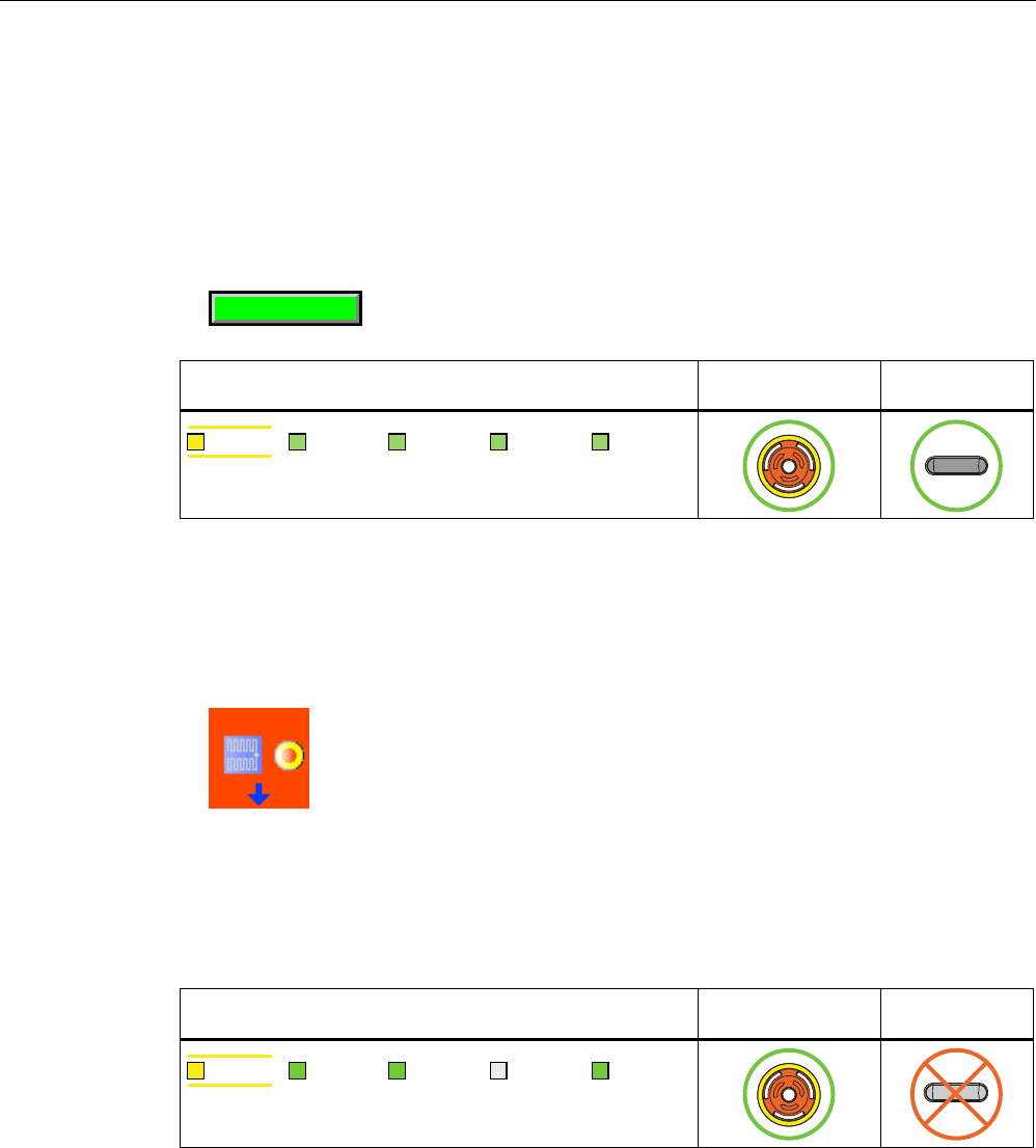
Appendix
A.2 Typical operating procedures and potential fault scenarios
Wireless Teach Pendant F IWLAN V2
262 Operating Instructions, 08/2010, A5E02453837-01
A.2.7 Leaving a protection zone without logging off
Requirement
● A security system is installed for the protection zone, for example, a photoelectric sensor
or a contact pressure mat.
● The HMI device has been logged on to a machine, such as "Robot 1", via an RFID tag.
5RERW
LED display EMERGENCY
STOP button
Enabling button
6$)( 3:5 &20 51* %$7
Procedure
1. You leave the protection zone with the HMI device through the security system.
The HMI device initiates a local rampdown.
The "Forced logoff" dialog opens with the following symbol.
2. Close the "Forced logoff" dialog with "OK".
Result
The HMI device is logged off the machine. The machine is free again for logon.
LED display EMERGENCY
STOP button
Enabling button
6$)( 3:5 &20 51* %$7
PRELIMINARY II
1.7.2010
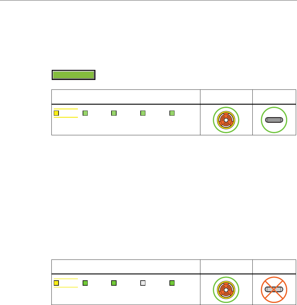
Appendix
A.2 Typical operating procedures and potential fault scenarios
Wireless Teach Pendant F IWLAN V2
Operating Instructions, 08/2010, A5E02453837-01 263
A.2.8 Communication errors with logged on HMI device
Starting situation
The HMI device is logged on to a machine.
5DQJHQDPH
LED display EMERGENCY
STOP button
Enabling button
6$)( 3:5 &20 51* %$7
Fault
A communication error occurs.
The F-CPU initiates a shutdown and stops the machine. The "SAFE" and "RNG" LEDs are
off.
The operator is alerted that no safety-related communication is available.
Result – Communication will be reestablished within 60 seconds
If the communication is reestablished within 60 seconds, the "Acknowledgment of
communication error" dialog will open.
If the operator acknowledges the communication error, the shutdown signal will be
cancelled. PROFIsafe communication is again possible. The machine is free again for logon.
LED display EMERGENCY
STOP button
Enabling button
6$)( 3:5 &20 51* %$7
Result – Communication remains interrupted for more than 60 seconds
If communication remains interrupted for more than 60 seconds, the project will be closed.
The HMI device displays the Windows CE Desktop with the loader.
Wireless network communication is reestablished if you later return to the WLAN range with
the HMI device. Start the project again. Acknowledge the communication error in the
"Acknowledgment of communication error" dialog.
The shutdown signal is revoked. The HMI device is fully operable.
PRELIMINARY II
1.7.2010
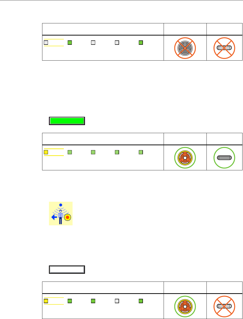
Appendix
A.2 Typical operating procedures and potential fault scenarios
Wireless Teach Pendant F IWLAN V2
264 Operating Instructions, 08/2010, A5E02453837-01
LED display EMERGENCY
STOP button
Enabling button
6$)( 3:5 &20 51* %$7
A.2.9 Logging off the machine
Requirement ● The HMI device is logged on to a machine.
● The "Effective range name" object will be displayed in green.
5DQJHQDPH
LED display EMERGENCY
STOP button
Enabling button
6$)( 3:5 &20 51* %$7
Procedure 1. Confirm the "Effective range name (RFID)" object.
The "Effective range logoff" dialog opens with the following symbol.
2. Confirm the logoff from the machine with the "Yes" button.
Result ● The HMI device is logged off the machine.
● The "Effective range name (RFID)" object is shown in white labeled "Scan".
6FDQ
LED display EMERGENCY
STOP button
Enabling button
6$)( 3:5 &20 51* %$7
PRELIMINARY II
1.7.2010
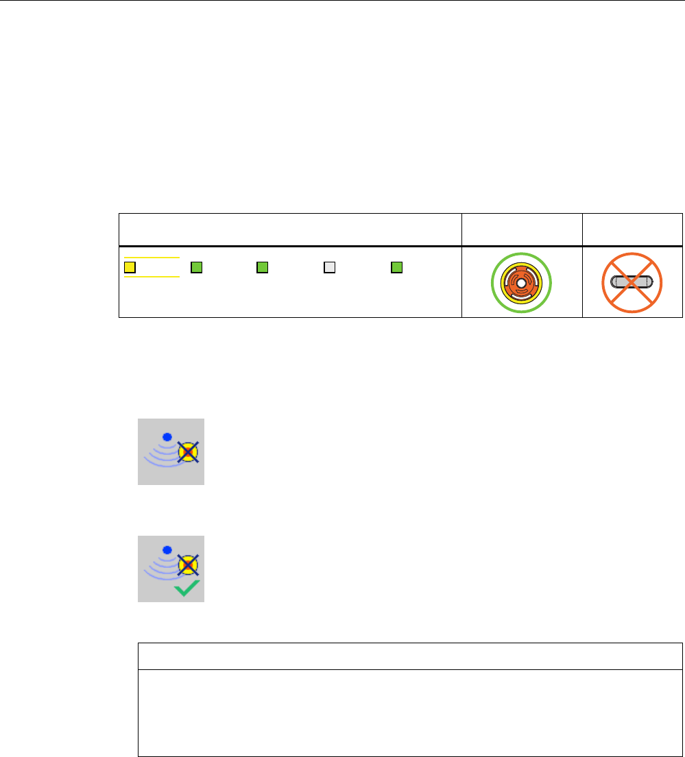
Appendix
A.2 Typical operating procedures and potential fault scenarios
Wireless Teach Pendant F IWLAN V2
Operating Instructions, 08/2010, A5E02453837-01 265
A.2.10 Removing the HMI device
Requirement
● The project must be started.
● The HMI device is integrated in the safety program of the F-CPU.
● The HMI device is not logged onto a machine.
LED display EMERGENCY
STOP button
Enabling button
6$)( 3:5 &20 51* %$7
Procedure
1. To close the project, use the operator control designed for this purpose.
The "Start removal" dialog opens with the following symbol.
2. Use the "Yes" button to confirm the removal.
The "Confirm removal" dialog opens with the following symbol.
3. Press an enabling button within 60 seconds.
NOTICE
Global rampdown
A global rampdown will occur, if you do not confirm the "Confirm removal" dialog within
60 seconds with the enabling button.
Press an enabling button within 60 seconds.
Result ● Safety-related communication is terminated.
● The HMI device has been successfully removed from the safety program of the F-CPU.
● The project is closed.
● The HMI device shows the Windows CE Desktop with the loader.
PRELIMINARY II
1.7.2010
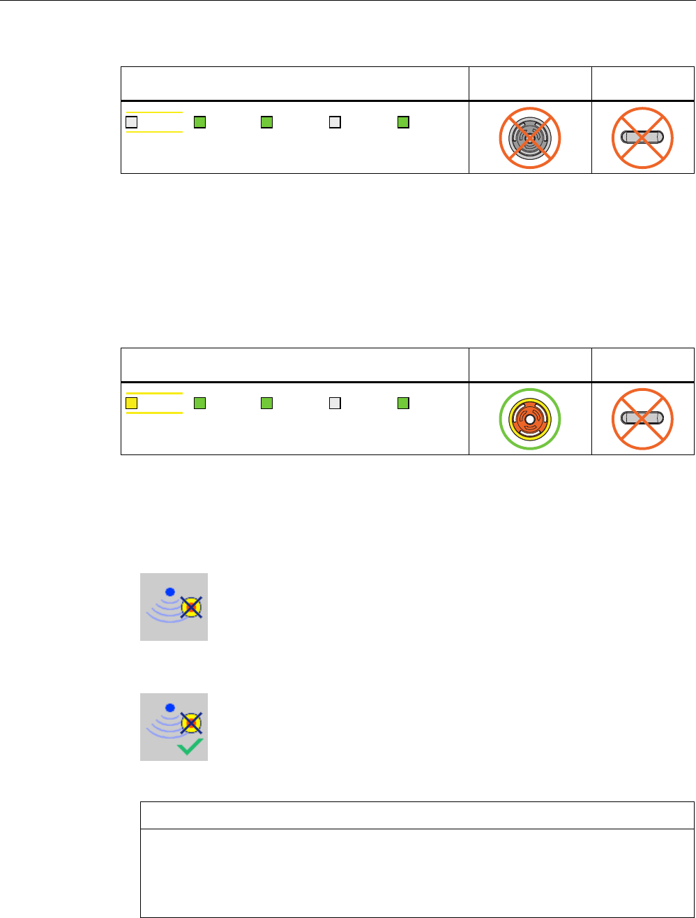
Appendix
A.2 Typical operating procedures and potential fault scenarios
Wireless Teach Pendant F IWLAN V2
266 Operating Instructions, 08/2010, A5E02453837-01
LED display EMERGENCY
STOP button
Enabling button
6$)( 3:5 &20 51* %$7
A.2.11 Switching off the HMI device
Requirement ● The project must be started.
● The HMI device is integrated in the safety program of the F-CPU.
LED display EMERGENCY
STOP button
Enabling button
6$)( 3:5 &20 51* %$7
Procedure 1. Close all open dialogs.
2. Press and hold the "ON/OFF" button for at least 4 seconds.
The "Start removal" dialog opens with the following symbol.
3. Use the "Yes" button to confirm the removal.
The "Confirm removal" dialog opens with the following symbol.
4. Press an enabling button within 60 seconds.
NOTICE
Global rampdown
A global rampdown will occur, if you do not confirm the "Confirm removal" dialog within
60 seconds with the enabling button.
Press an enabling button within 60 seconds.
PRELIMINARY II
1.7.2010
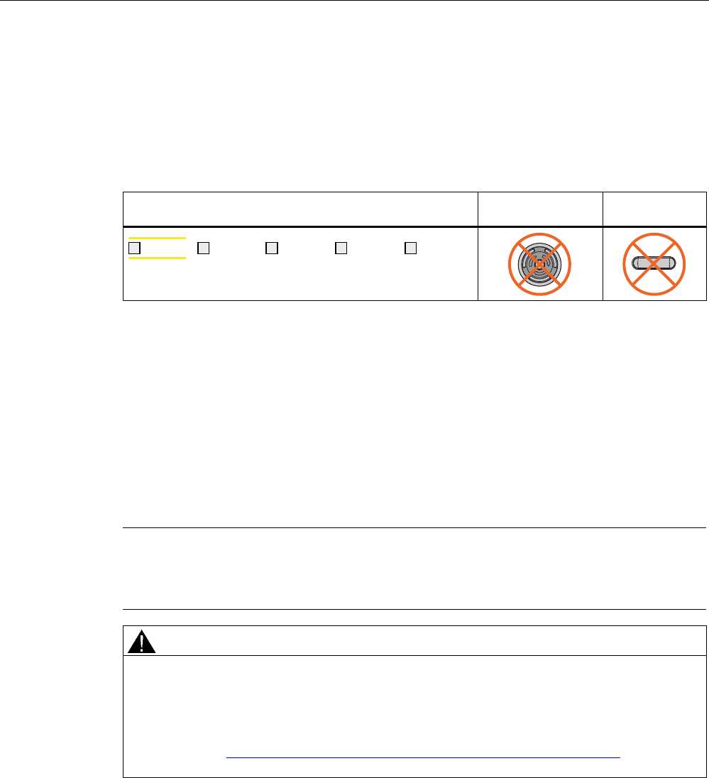
Appendix
A.3 Example of an application
Wireless Teach Pendant F IWLAN V2
Operating Instructions, 08/2010, A5E02453837-01 267
Result
● Safety-related communication is terminated.
● The HMI device has been successfully removed from the safety program of the F-CPU.
● The project is closed.
● The HMI device will be switched off.
LED display EMERGENCY
STOP button
Enabling button
6$)( 3:5 &20 51* %$7
A.3 Example of an application
A.3.1 Configuration and operation
This application example shows one possible application with the safety features of the HMI
device.
Note
In this example, the HMI device is logged onto a machine via an RFID tag within a protection
zone. The security system of the protection zone consists of a wire mesh fence with a door
and a contact pressure mat.
WARNING
Read the documentation for S7 Distributed Safety
An incorrectly configured or programmed system can result in death or serious injuries.
We highly recommend that you read the information on S7 Distributed Safety in
Programming and operation manual "S7 Distributed Safety - Configuring and
Programming" (http://support.automation.siemens.com/WW/view/en/22099875) and in the
online help of S7 Distributed Safety.
PRELIMINARY II
1.7.2010
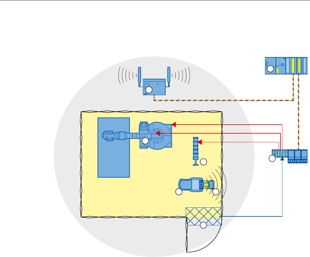
Appendix
A.3 Example of an application
Wireless Teach Pendant F IWLAN V2
268 Operating Instructions, 08/2010, A5E02453837-01
Configuration example
The following example configuration shows a robot cell which is secured by a wire mesh
fence with a contact pressure mat.
(
$
$
$
352),VDIH
① Access point
② Fail-safe controller
③ Robot
④ Signal lamp
⑤ F-I/O, PROFINET IO device
⑥ HMI device
⑦ RFID tag
⑧ Contact pressure mat
The following signals are used:
PRELIMINARY II
1.7.2010
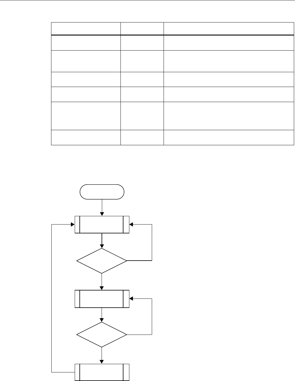
Appendix
A.3 Example of an application
Wireless Teach Pendant F IWLAN V2
Operating Instructions, 08/2010, A5E02453837-01 269
Function
Symbolic name Signal Explanation
Contact pressure mat
"Contact_Mats"
I11.0 "0": Step on contact pressure mat
"1": Do not step on contact mat
"Key1" button, configured
as direct key on the HMI
device:
E0.0 "0": Button not pressed
"1": Button pressed
Enabling button ENABLE
(F_FB_RNG_4)
"0": No enable
"1": Enable
Power ON-OFF robot
"E_Stop_Robot"
O11.0 "0": EMERGENCY STOP triggered.
"1": Normal operation of plant.
Actuator to robot O11.1 "0": The robot is not operated with Key1 and the
enabling buttons
"1": The robot is operated with Key1 and the enabling
buttons
Signal lamp O 11.2 "0": Robot is not in use; the signal lamp is off
"1": Robot is in use; the signal lamp is on
Flowchart
The following flowchart shows the operation sequence in the example.
Start
Log on to the
machine?
Yes
No
Operation in the
protection zone is
possible
Contact with
pressure mat?
Forced logoff
Yes
No
Operation in the
protection zone not
possible
PRELIMINARY II
1.7.2010
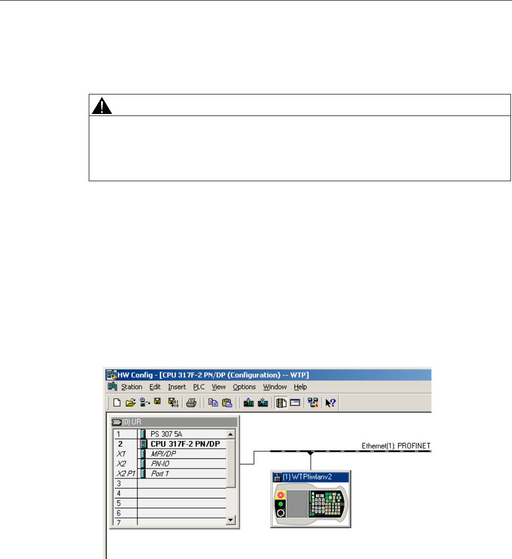
Appendix
A.3 Example of an application
Wireless Teach Pendant F IWLAN V2
270 Operating Instructions, 08/2010, A5E02453837-01
A.3.2 Configuring the controller and HMI device in STEP 7
This section describes the most important parameters you need to set in "HW Config" for the
F-CPU and for the HMI device.
WARNING
Safety category
Any changes to parameters may result in the loss of the safety category.
Set the parameters as described. The parameters will contribute to meeting safety
category 4 PL e/SIL 3.
Requirement
The software for fail-safe operation has been installed, see section "Required software
(Page 22)".
Procedure – Configuring CPU 317F-2 PN/DP
Proceed as follows:
1. Create a STEP 7 project in SIMATIC Manager.
2. Open the "HW Config" hardware configuration and insert the desired F-CPU and a
PROFINET connection, as shown in the following figure:
3. Open the settings by double-clicking the F-CPU in "HW Config".
The table below shows the most important settings:
PRELIMINARY II
1.7.2010
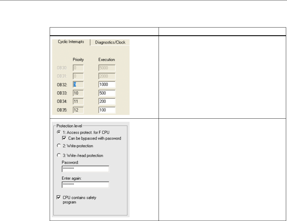
Appendix
A.3 Example of an application
Wireless Teach Pendant F IWLAN V2
Operating Instructions, 08/2010, A5E02453837-01 271
Setting Explanation
This is where you set the cycle time for OB35.
Note
If the cycle time for OB35 is set lower than the PBIO
update time, the message frame may be lost and the
evaluation of the "E-STOP" output of F_FB_RNG_4
or F_FB_RNG_16 may be delayed.
Set the cycle time of OB35 to a value higher than the
PNIO update time.
Assign a password for the safety program.
Set the "CPU contains safety program" check box.
This setting is required to generate all the necessary
F-FBs for safe operation of the fail-safe modules
during compilation of "HW Config" by STEP 7.
PRELIMINARY II
1.7.2010
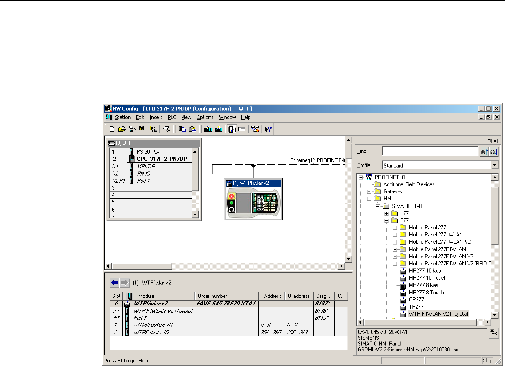
Appendix
A.3 Example of an application
Wireless Teach Pendant F IWLAN V2
272 Operating Instructions, 08/2010, A5E02453837-01
Procedure – Configuring Wireless Teach Pendant F IWLAN
Proceed as follows:
1. Insert the Wireless Teach Pendant F IWLAN in "HW Config" as shown in the following
figure.
2. Open the properties dialog of the HMI device by double-clicking the "WTPfiwlan" icon.
3. Enter the device name of the HMI device in the properties dialog.
4. Open the properties dialog of the "WTPFailsafe_IO" module by double-clicking the
"WTPFailsafe_IO" entry in the detailed view of the HMI device.
5. Change to the "PROFIsafe" tab.
PRELIMINARY II
1.7.2010
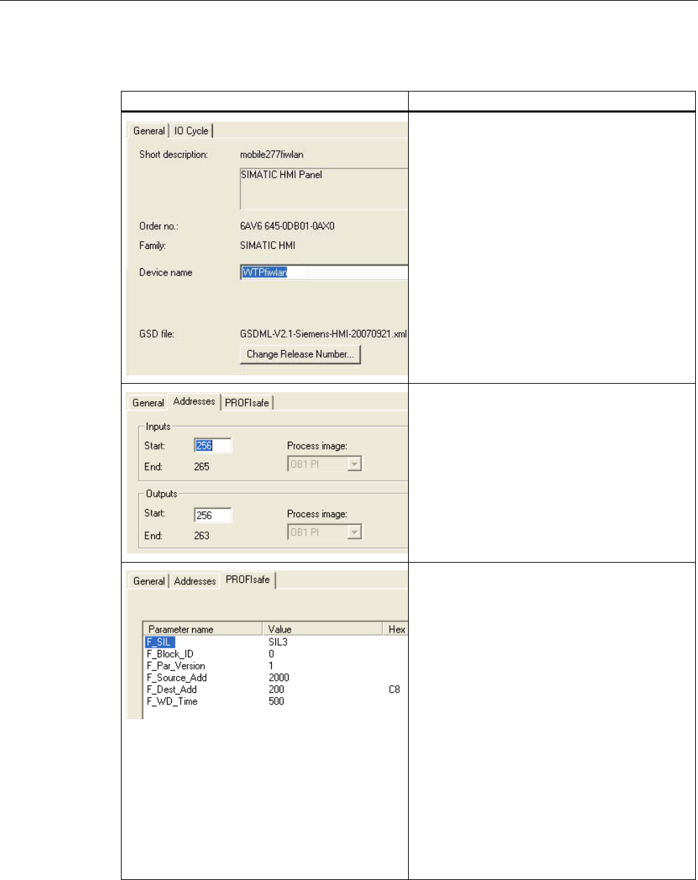
Appendix
A.3 Example of an application
Wireless Teach Pendant F IWLAN V2
Operating Instructions, 08/2010, A5E02453837-01 273
The table below shows the most important settings:
Setting Explanation
Device name
Here you assign a device name to the HMI
device, which is unique in the local Ethernet
network segment. This name must match the
name defined in the Control Panel of the HMI
device under "PROFINET" in the text box "Device
name:".
Additional information is available in the section:
"Specifying the computer name of the HMI device
(Page 145)".
Inputs
This is where you specify the start address of the
inputs and the process image associated with this
address area (PII).
Outputs
Here you specify the start address of the outputs
and the process image associated with this
address area (PIQ).
F_Dest_Add
PROFIsafe address of the
Wireless Teach Pendant F IWLAN. This address
must match the address on the HMI device.
F_WD_Time
Monitoring time in the fail-safe IO device.
A valid current safety message frame must reach
the F-CPU and be returned to the HMI device
within the monitoring time period. This ensures
that failures and errors are detected and
appropriate responses are triggered to keep the
fail-safe system in a safe state or transfer it to a
safe state.
The monitoring time selected must be long
enough that message frame delays will be
tolerated by the communication system, but also
that the fault reaction function responds quickly
enough in the event of a fault (e.g. interruption in
the communication connection).
PRELIMINARY II
1.7.2010
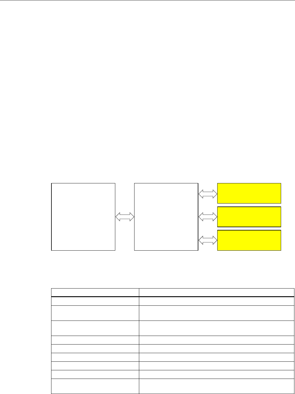
Appendix
A.3 Example of an application
Wireless Teach Pendant F IWLAN V2
274 Operating Instructions, 08/2010, A5E02453837-01
A.3.3 Safety program S7 Distributed Safety
In the safety program of the S7-CPU, the operation sequence of the application example is
implemented by the following programming:
● Once the HMI device is logged on to a machine, the signal lamp and the "Override" mode
are enabled.
● In the protection zone, the operator can operate the robot with the "Key1" button and the
enabling button.
● If the operator leaves the protection zone over the contact pressure mat, the safety
program responds as follows:
– The signal lamp goes out.
– "Override" mode is deactivated.
– The HMI device is logged off the machine.
● After an EMERGENCY STOP, the plant only restarts when the operator performs an
acknowledgment.
● Reactions specific to a plant are initiated when a rampdown or shutdown occurs.
Safety program The safety program is structured as follows:
)% )B)%B03))%
)B)%B51*))%
)B(6723))%
)&DOO
)&
Symbolic names
The following symbolic names are used in the networks of the sample programs
Symbolic name Meaning
F00256_WTPFailsafe_IO Fail-safe I/O DB of HMI device
MP1_FB_S7_MP_RE Input which is set when a reset of the HMI device is performed
from the F-CPU.
MP1_FB_S7_ACK_ERR Input which is set when a communication error is acknowledged
from the F-CPU.
MP1_F_DATA_PII Word 1 of the PII of the HMI device
MP1_F_RANGE_PII Word 2 of the PII of the HMI device
MP1_F_DATA_PIQ Word 1 of the PIQ of the HMI device
MP1_F_RANGE_PIQ Word 2 of the PIQ of the HMI device
Interface_DB F-DB for the data transfer of user data
F_DB_States F-DB for the transfer of data between the F_FB_MP of the HMI
device and the F_FB_RNG_n of the effective range
PRELIMINARY II
1.7.2010

Appendix
A.3 Example of an application
Wireless Teach Pendant F IWLAN V2
Operating Instructions, 08/2010, A5E02453837-01 275
F-CALL (FC 1)
F-CALL (FC1) is the F-run-time group and is called from the cyclic interrupt OB (OB35).
F-CALL (FC1) calls the F-program block (in this case: FB1).
FB1
For reasons of program modularity, all other F-FBs are called from this FB.
In FB 1, you have to call the F-FBs in the following order.
1. Network 1
)B:73)DLOVDIHB,2ಯ$&.B5(,
03B)B'$7$B3,4ಯ
03B)B51*B3,4
,QWHUIDFHB'%03B)%B',$*
'%
(1
4%$'
$&.B5(4
6B03B5(6
6B$&.B(55
03B'$7$
03B51*
03B67$7
$&.B5(,
03B'$7$B4
03B51*B4
',$*
(12
)B)%B03
)B:73)DLOVDIHB,24%$'
)B:73)DLOVDIHB,2$&.B5(4
03B)%B6B03B5(
03B)%B6B$&.B(55
03B)B'$7$B3,,
03B)B51*B3,,
)B'%B67$7(603BB6WDWXV
The controller uses this F-FB to monitor the PROFIsafe communication of the HMI
device. The following diagnostics information is indicated at the "DIAG" output:
– Status of the HMI device: integrated or removed
– A communication error has occurred.
– Communication error must be acknowledged
Additional information is available in F_FB_MP (Page 171).
PRELIMINARY II
1.7.2010
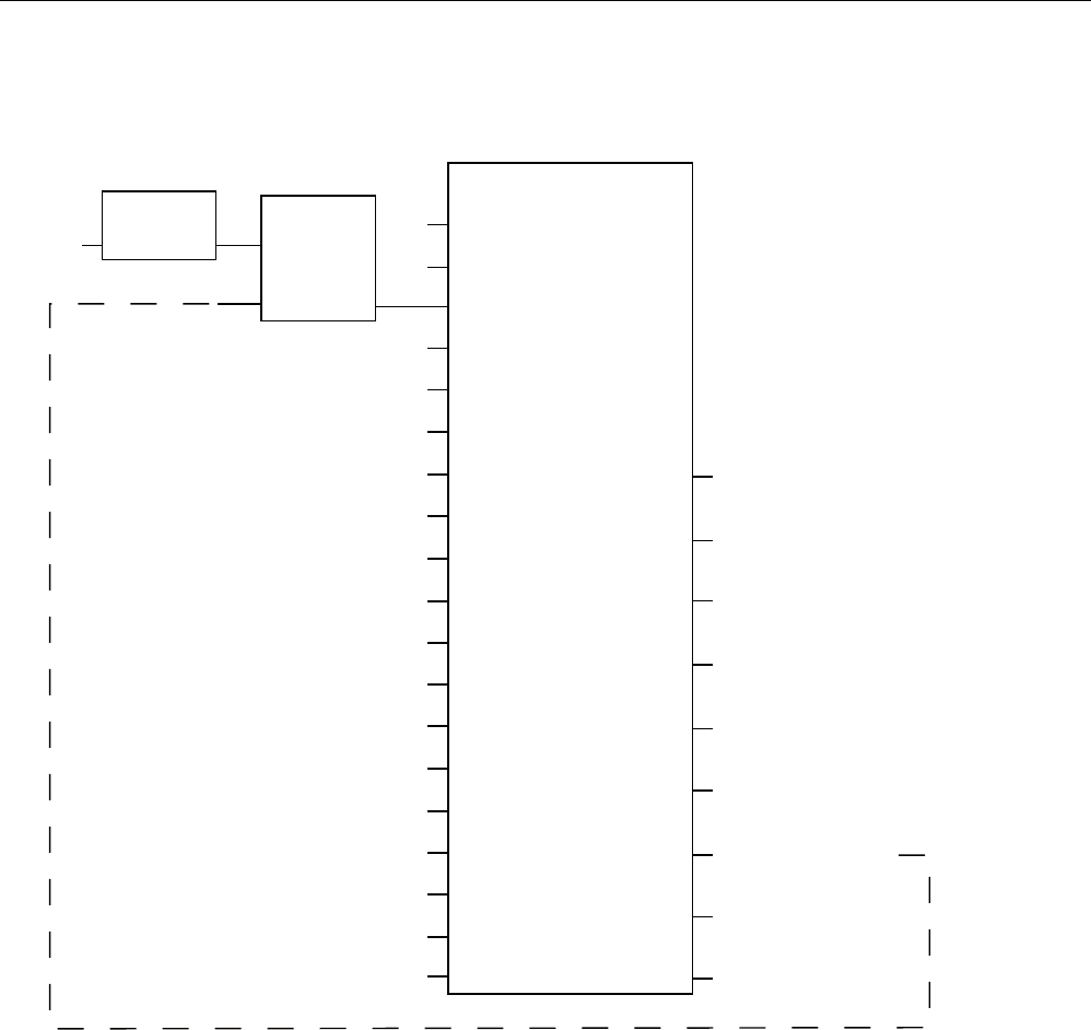
Appendix
A.3 Example of an application
Wireless Teach Pendant F IWLAN V2
276 Operating Instructions, 08/2010, A5E02453837-01
2. Network 2
(GJHB
&RQWDFWB
0DWV
1(*
0B%,7 4
&RQWDFWB0DWV )B)%B51*B
'%
(1
51*B,'
29(55,'(
03B'$7$
03B51*
03B)B.(<
03B'$7$
03B51*
03B)B.(<
03B'$7$
03B51*
03B)B.(<
03B'$7$
03B51*
03B)B.(<
03B67$7
03B67$7
03B67$7
03B67$7
(B6723
*/2%B5'
/2&B5'
6+87'2:1
(1$%/(
)B.(<6
51*B%86<
',$*
(12
,QWHUIDFHB'%
(5B(B6723
,QWHUIDFHB'%
(5B*/2%B5'
,QWHUIDFHB'%
(5B/2&B5'
,QWHUIDFHB'%
(5B6+87'2:1
,QWHUIDFHB'%
(5B(1$%/(
,QWHUIDFHB'%
(5B51*B%86<
,QWHUIDFHB'%
(5B)%B',$*
03B)B'$7$B3,,
03B)B51*B3,,
)B'%B67$7(6
03BB6WDWXV
,QWHUIDFHB'%
(5B51*B%86<
The activation of the "override" mode is controlled in this network.
"OVERRIDE" is set as soon as the operator has logged the HMI device on to the machine
via the RFID tag. (RNG_BUSY). "OVERRIDE" is reset by a negative edge on the contact
pressure mat, in other words I11.0 = "0". This is the case when the operator leaves the
protection zone.
At the same time, F_FB_RNG monitors the signals "EMERGENCY STOP", "Global
rampdown", "Local rampdown" and "Shutdown". They are scanned in networks 3 to 6.
PRELIMINARY II
1.7.2010
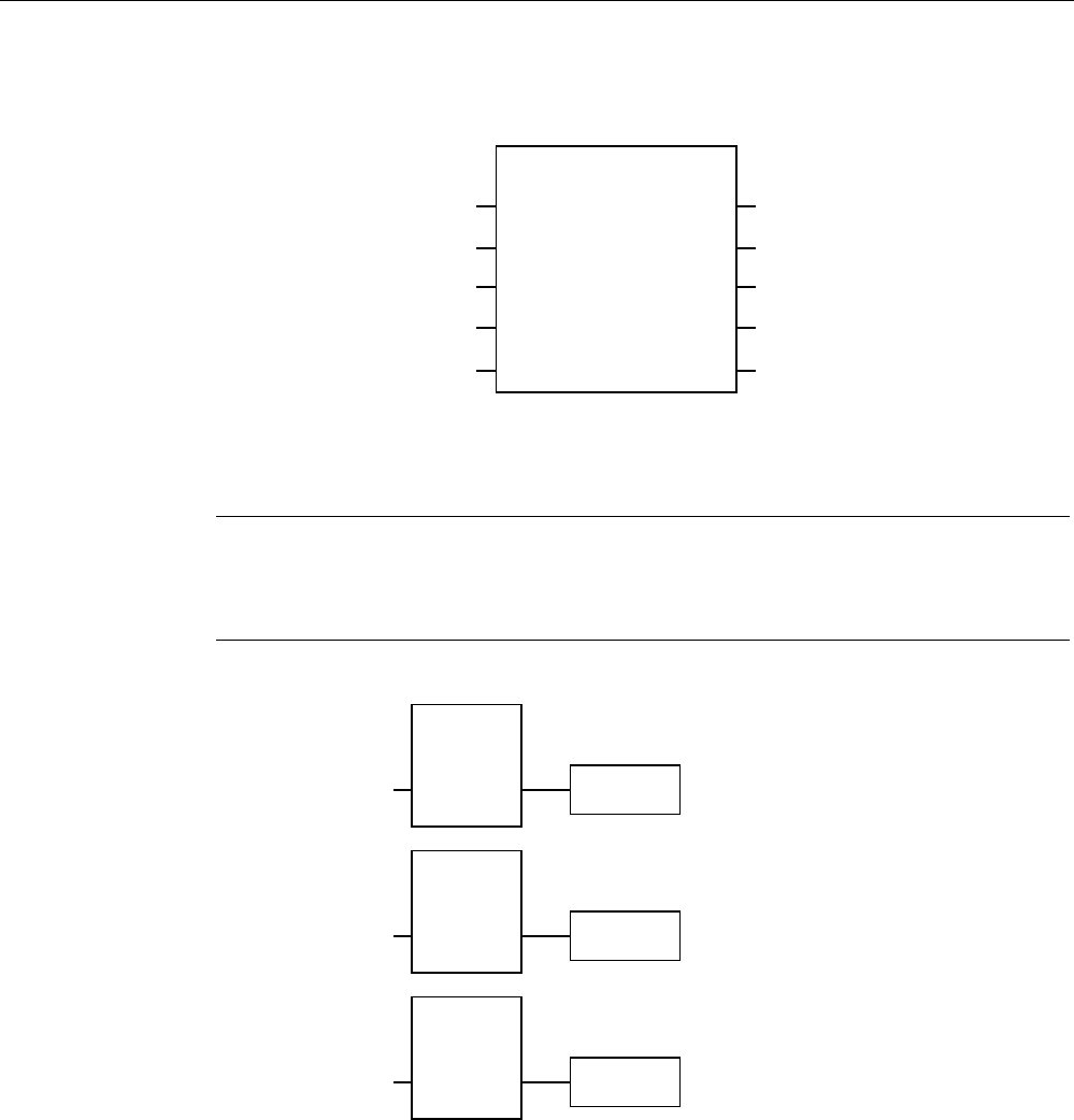
Appendix
A.3 Example of an application
Wireless Teach Pendant F IWLAN V2
Operating Instructions, 08/2010, A5E02453837-01 277
3. Network 3
)B(6723
'%
,QWHUIDFHB'%(5B(B6723
(B6WRSB5RERW(1
(B6723
$&.B1(&
$&.
7,0(B'(/
4
4B'(/$<
$&.B5(4
',$*
(12
In network 3, the EMERGENCY STOP signal of the HMI device is monitored via
F_ESTOP1 from the F-library of S7 Distributed Safety. F_ESTOP1 ensures that the plant
is only able to restart following an EMERGENCY STOP after acknowledgment by the
operator via the input "ACK".
Note
Read also the information on FB215 in the online help for F-FBs and in the manual
"SIMATIC S7-Distributed Safety, Configuring and Programming", section "FB215
"F_ESTOP1:" Emergency STOP up to Stop Category 1".
4. Networks 4, 5 and 6
*OREDOB5DPSGRZQ
/RFDOB5DPSGRZQ
6KXWGRZQ
,QWHUIDFHB'%
(5B*/2%B5'
,QWHUIDFHB'%
(5B/2&B5'
,QWHUIDFHB'%
(5B6+87'2:1
In network 4, 5 and 6 the signals for a global and a local rampdown and shutdown are
processed further. As the configuration of the monitored plant determines which
responses have to occur following occurrence of a particular safety state, these networks
are not explained in detail in this example.
PRELIMINARY II
1.7.2010

Appendix
A.3 Example of an application
Wireless Teach Pendant F IWLAN V2
278 Operating Instructions, 08/2010, A5E02453837-01
5. Network 7
(
$
,QWHUIDFHB'%
(5B(QDEOH
If the operator simultaneously presses the Key1 key and the enabling button, the robot is
activated via the output Q11.1.
6. Network 8
,QWHUIDFHB'%
(5B51*B%86<
$
If the "RNG_BUSY" signal is set in F_FB_RNG, output Q11.2 is used to control the signal
lamp that indicates whether or not the machine is in use.
PRELIMINARY II
1.7.2010
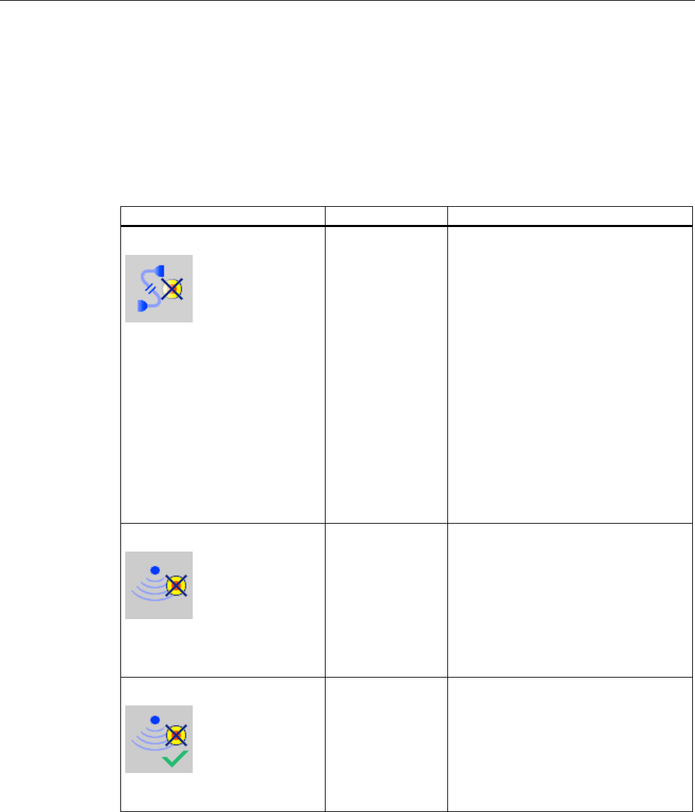
Appendix
A.4 Safety-related messages
Wireless Teach Pendant F IWLAN V2
Operating Instructions, 08/2010, A5E02453837-01 279
A.4 Safety-related messages
The following safety-related messages are displayed in fail-safe mode depending on the
operating situation. In contrast to system alarms, no message window needs to be
configured for safety-related messages.
Dialog Reaction Situation
Establishment of safety connection
No safe connection available.
Reason:
Connection not yet completed
PROFIsafe address error
Internal configuration error
Communication error (timeout)
Communication error (CRC)
CPU in STOP
PROFIsafe CRC configuration
error
Should the Panel be switched off?
"Yes" button The following is reported in the warning
message depending on the operating
situation:
Connection not yet completed
The safe connection is not yet
established after the project has been
started. Wait until the connection has
been established. The dialog is closed
on completion.
A communication error occurred after
the HMI device was successfully
integrated. Correct the cause of the
error described by "Reason".
Start removal
The removal cannot be interrupted
once it has started.
Do you want to start the removal?
"Yes" button
"No" button
The "Start removal" dialog opens in the
following cases:
The operator has pressed the
"ON/OFF" button for more than
4 seconds.
The operator has pressed the operator
control for closing the project.
Confirm removal
Please confirm the removal with
the enabling button.
Press an enabling
button until the
"Enable" switch
position is reached.
The removal starts, in other word, the user
has pressed the "Yes" button in the "Start
removal" dialog.
PRELIMINARY II
1.7.2010
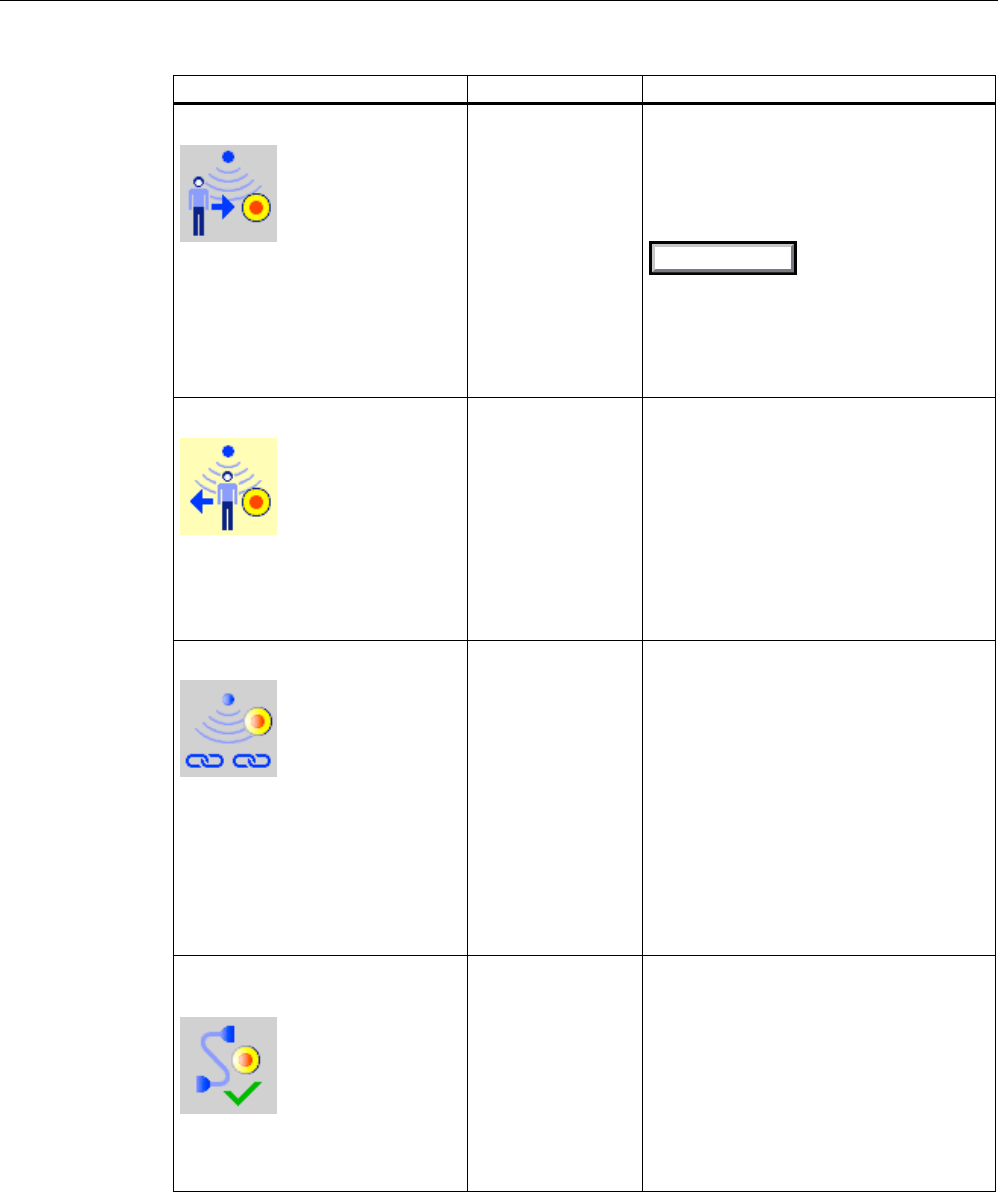
Appendix
A.4 Safety-related messages
Wireless Teach Pendant F IWLAN V2
280 Operating Instructions, 08/2010, A5E02453837-01
Dialog Reaction Situation
Effective range logon
Do you want to logon to the
following effective range?
Effective range <<EFFECTIVE
RANGE NAME>>
Please enter the effective range
ID:
"Yes" button
"No" button
The HMI device is located directly in front
of an RFID tag and is not yet logged on to
the corresponding machine.
The operator has activated the "Scan"
object to log on.
6FDQ
Effective range logoff
Do you want to log off from the
following effective range?
Effective range <<EFFECTIVE
RANGE NAME>>
"Yes" button
"No" button
The HMI device is logged on to a
machine.
The operator has activated the "Effective
range name (RFID)" object to log off.
Effective range logoff (shutdown)
The Panel cannot be switched off.
You first have to log off from the
effective range.
Do you want to logoff from the
following effective range?
Effective range <<EFFECTIVE
RANGE NAME>>
"Yes" button
"No" button
The HMI device is logged on to a
machine.
The operator has attempted to:
Shut down the HMI device.
Close the project with the
corresponding operator control.
Acknowledgment of
communication error
A safe connection is possible
again. Please confirm the
communication error.
"OK" button Communication was recovered after a
short communication error. The operator
must confirm this state.
Causes:
The operator has briefly left the WLAN
range and then returned.
PROFIsafe communication was briefly
interrupted.
PRELIMINARY II
1.7.2010
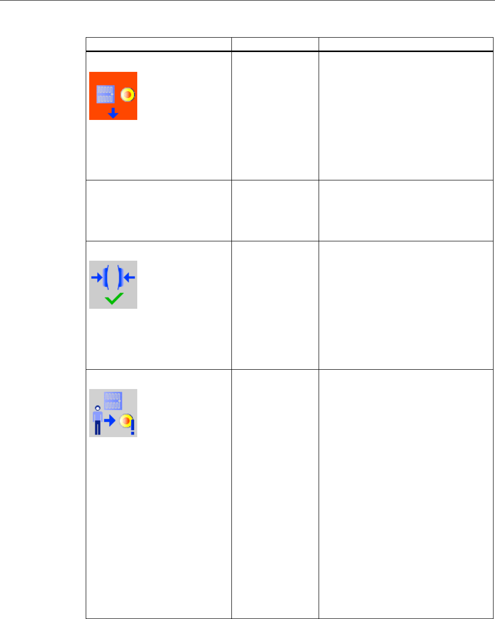
Appendix
A.4 Safety-related messages
Wireless Teach Pendant F IWLAN V2
Operating Instructions, 08/2010, A5E02453837-01 281
Dialog Reaction Situation
Forced logoff
You are automatically logged off
from the effective range.
A local rampdown has been
triggered! Confirm the logoff from
the effective range.
"OK" button The operator has left the protection zone
with a logged-on HMI device via the safety
system.
Low battery alarm
Battery charge is less than 20
percent.
"OK" button The remaining charge of the main
rechargeable battery is less than 20%.
An additional system alarm is output after
the charge of the main rechargeable
battery has dropped to less than 6%.
Test enabling button
Both enabling buttons must be
tested to ensure they are
operational. Fully press both
enabling buttons until the panic
position is reached.
Press both enabling
buttons until the
"Panic" switch
position is reached.
The operator has started the project.
Perform a function test for the enabling
button.
Error during effective range logon
Error during effective range logon.
The enabling button remains
deactivated.
"OK" button An error occurred during logon of the HMI
device to a machine. The operator cannot
use the enable switches to control the
production process.
Possible causes:
You are already logged on to the
machine with your HMI device or the
logon is currently in progress.
Another HMI device is already logged
on to the machine.
RFID tag is defective.
RFID module in the HMI device is
defective.
No ID has been assigned to the RFID
tag.
The operator has entered an incorrect
RFID tag ID for the logon.
F_FB_RNG missing in the STEP7
configuration.
F_FB_RNG is wired incorrectly in
STEP7.
PRELIMINARY II
1.7.2010
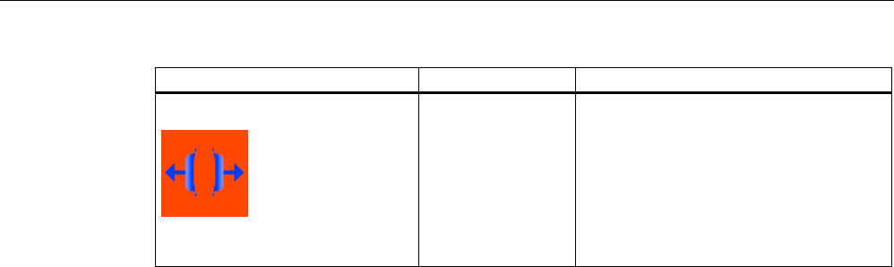
Appendix
A.4 Safety-related messages
Wireless Teach Pendant F IWLAN V2
282 Operating Instructions, 08/2010, A5E02453837-01
Dialog Reaction Situation
Enabling switch discrepancy error
Please release the enabling
button.
Release both
enabling buttons.
The HMI device detects a discrepancy at
one of the two enabling buttons in switch
position "Enable".
See also
Communication error for the integrated HMI device (Page 256)
PRELIMINARY II
1.7.2010

Appendix
A.5 System alarms
Wireless Teach Pendant F IWLAN V2
Operating Instructions, 08/2010, A5E02453837-01 283
A.5 System alarms
Introduction
System alarms on the HMI device provide information about internal states of the HMI device
and PLC.
The following overview shows the causes of system alarms and how to eliminate the cause
of error.
Some of the system alarms described in this section are relevant to individual HMI devices
based on their range of features.
Note
System alarms are only indicated if an alarm window was configured. System alarms are
output in the language currently set on your HMI device.
System alarm parameters
System alarms may contain encrypted parameters which are relevant to troubleshooting
because they provide a reference to the source code of the runtime software. These
parameters are output after the text "Error code:"
Displaying the "System alarms" editor
You can find the text content of the system alarm in WinCC flexible. The "System alarms"
editor is not displayed by default in WinCC flexible.
1. Enable the "System alarms" editor under "Options > Setting... > Workbench > Settings for
Project Window" with "Display all entries".
2. Select the "System alarms" editor under "Alarms" in the project view.
The system alarms are sorted numerically in the "System alarms" editor.
Configuring events for system alarms
You can configure the "Incoming" event for the following system alarm in the "System
alarms" editor.
System alarms
10000
10000 to 10006
150000
150000
150001
230300
230300 to 230308
20000
20000 to 20015
160000
160000
160001
160010 to 160014
240000
240000 to 240005
30000
30010 to 20012
170000
170000 to 170004
170007
250000
250000 to 250003
PRELIMINARY II
1.7.2010

Appendix
A.5 System alarms
Wireless Teach Pendant F IWLAN V2
284 Operating Instructions, 08/2010, A5E02453837-01
System alarms
40000
40010
40011
180000
180000 to 180002
260000
260000 to 260009
260012 to 260014
260028
260030
260033 to 260045
50000
50000
50001
190000
190000 to 190002
190004 to 190013
270000
270000 to 270003
60000
60010 to 60011
190100
190100 to 190102
280000
280000 to 280004
70000
70010 to 70044
200000
200000 to 200005
290000
290000 to 290008
290010 to 290014
290020 to 290027
290040 to 290042
290044
290050 to 290065
290070 to 290073
290075
80000
80001 to 80035
80044 to 80050
200100
200100 to 200105
300000
300000
300001
90000
90024 to 90026
90029 to 90033
90040
90041
90044
210000
210000 to 210006
310000
310000
310001
110000
110000 to 110006
220000
220000 to 220008
600000
600000
120000
120000 to 120002
230000
230000
230002
200003
200005
620000
620000
130000
130000 to 130012
230100
230100
140000
140000 to 140020
230200
230200 to 230203
PRELIMINARY II
1.7.2010

Appendix
A.5 System alarms
Wireless Teach Pendant F IWLAN V2
Operating Instructions, 08/2010, A5E02453837-01 285
10000 - Printer alarms
Number Effect/cause Remedy
10000 The print job could not be started or was canceled due
to an unknown error. Faulty printer setup. Or: No
authorization is available for accessing the network
printer.
Power supply failure during data transfer.
Check the printer settings, cable connections and the
power supply.
Set up the printer once again. Obtain a network printer
authorization.
If the error persists, contact the Hotline!
10001 No printer is installed or a default printer has not been
set up.
Install a printer and/or select it as the default printer.
10002 Overflow of the graphics buffer for printing. Up to two
graphics are buffered.
Allow sufficient intervals between successive print jobs.
10003 Graphics can now be buffered again. --
10004 Overflow of the buffer for printing lines in text mode
(e.g. alarms). Up to 1000 lines are buffered.
Allow sufficient intervals between successive print jobs.
10005 Text lines can now be buffered again. --
10006 The Windows printing system reports an error. Refer
to the output text and the error ID to determine the
possible causes. Nothing is printed or the print is
faulty.
Repeat the action if necessary.
20000 - Global script alarms
Number Effect/causes Remedy
20010 An error has occurred in the specified script line.
Execution of the script was therefore aborted. Note
the system alarm that may have occurred prior to this.
Select the specified script line in the configuration.
Ensure that the tags used are of the allowed types.
Check system functions for the correct number and
types of parameters.
20011 An error has occurred in a script that was called by
the specified script.
Execution of the script was therefore aborted in the
called script.
Note the system alarm that may have occurred prior
to this.
In the configuration, select the script that has been
called directly or indirectly by the specified script.
Ensure that the tags used are of the allowed types.
Check system functions for the correct number and
types of parameters.
20012 The configuration data is inconsistent. The script
could therefore not be generated.
Recompile the configuration.
20013 The scripting component of WinCC flexible Runtime is
not correctly installed. Therefore, no scripts can be
executed.
Reinstall WinCC flexible Runtime on your PC.
Rebuild your project with "Project > Compiler >
Generate" and transfer the project to the HMI device.
20014 The system function returns a value that is not written
in any return tag.
Select the specified script in the configuration.
Check whether the script name has been assigned a
value.
20015 Too many successive scripts have been triggered in
short intervals. When more than 20 scripts are
queued for processing, any subsequent scripts are
rejected. In this case, the script indicated in the alarm
is not executed.
Find what is triggering the scripts. Extend the times,
e.g. the polling time of the tags which trigger the
scripts.
PRELIMINARY II
1.7.2010

Appendix
A.5 System alarms
Wireless Teach Pendant F IWLAN V2
286 Operating Instructions, 08/2010, A5E02453837-01
30000 - Alarms for IFwSetValue: SetValue()
Number Effect/causes Remedy
30010 The tag could not accept the function result, e.g.
when it has exceeded the value range.
Check the tag type of the system function parameter.
30011 A system function could not be executed because
the function was assigned an invalid value or type in
the parameter.
Check the parameter value and tag type of the invalid
parameter. If a tag is used as a parameter, check its
value.
30012 A system function could not be executed because
the function was assigned an invalid value or type in
the parameter.
Check the parameter value and tag type of the invalid
parameter. If a tag is used as a parameter, check its
value.
40000 - Linear scaling alarms
Number Effect/causes Remedy
40010 The system function could not be executed since
the parameters could not be converted to a common
tag type.
Check the parameter types in the configuration.
40011 The system function could not be executed since
the parameters could not be converted to a common
tag type.
Check the parameter types in the configuration.
50000 - Data server alarms
Number Effect/causes Remedy
50000 The HMI device is receiving data faster than it is
capable of processing. Therefore, no further data is
accepted until all current data have been processed.
Data exchange then resumes.
--
50001 Data exchange has been resumed. --
60000 - Win32 function alarms
Number Effect/causes Remedy
60000 This alarm is generated by the
“DisplaySystemAlarms” function. The text to be
displayed is transferred to the function as a
parameter.
--
60010 The file could not be copied in the direction defined
because one of the two files is currently open or the
source/target path is not available.
It is possible that the Windows user has no access
rights to one of the two files.
Restart the system function or check the paths of the
source/target files. Using Windows NT/XP: The user
running WinCC flexible Runtime must be granted access
rights to the files.
60011 An attempt was made to copy a file to itself.
It is possible that the Windows user has no access
rights to one of the two files.
Check the path of the source/target file.
Using Windows NT/XP with NTFS: The user running
WinCC flexible Runtime must be granted access rights to
the files.
PRELIMINARY II
1.7.2010

Appendix
A.5 System alarms
Wireless Teach Pendant F IWLAN V2
Operating Instructions, 08/2010, A5E02453837-01 287
70000 - Win32 function alarms
Number Effect/causes Remedy
70010 The application could not be started because it could
not be found in the path specified or there is
insufficient memory space.
Check whether the application exists in the specified
path or close other applications.
70011 The system time could not be modified.
The error alarm only appears in connection with area
pointer "Date/time PLC". Possible causes:
An invalid time was transferred in the job mailbox.
The Windows user has no right to modify the
system time.
If the first parameter in the system alarm is displayed
with the value 13, the second parameter indicates the
byte containing the incorrect value.
Check the time which is to be set.
Using Windows NT/XP: Users running WinCC flexible
Runtime must be granted the right to modify the
system time of the operating system.
70012 An error occurred when executing the function
"StopRuntime" with the option "Runtime and operating
system".
Windows and WinCC flexible Runtime are not closed.
One possible cause is that other programs cannot be
closed.
Close all programs currently running.
Then close Windows.
70013 The system time could not be modified because an
invalid value was entered. Incorrect separators may
have been used.
Check the time which is to be set.
70014 The system time could not be modified. Possible
causes:
An invalid time was transferred.
The Windows user has no right to modify the
system time.
Windows rejects the setting request.
Check the time which is to be set.
Using Windows NT/XP: Users running WinCC flexible
Runtime must be granted the right to modify the
system time of the operating system.
70015 The system time could not be read because Windows
rejects the reading function.
--
70016 An attempt was made to select a screen by means of
a system function or job. This is not possible because
the screen number specified does not exist.
Or: A screen could not be generated due to
insufficient system memory.
Or: The screen is blocked.
Or: Screen call has not been executed correctly.
Check the screen number in the function or job with the
screen numbers configured.
Assign the number to a screen if necessary.
Check the details for the screen call and whether the
screen is blocked for specific users.
70017 Date/time is not read from the area pointer because
the address set in the PLC is either not available or
has not been set up.
Change the address or set up the address in the PLC.
70018 Acknowledgment that the password list has been
successfully imported.
--
70019 Acknowledgment that the password list has been
successfully exported.
--
70020 Acknowledgment for activation of alarm reporting. --
70021 Acknowledgment for deactivation of alarm reporting. --
70022 Acknowledgment to starting the Import Password List
action.
--
PRELIMINARY II
1.7.2010

Appendix
A.5 System alarms
Wireless Teach Pendant F IWLAN V2
288 Operating Instructions, 08/2010, A5E02453837-01
Number Effect/causes Remedy
70023 Acknowledgment to starting the Export Password List
action.
--
70024 The range of values of the tag was exceeded in the
system function.
No calculation of the system function.
Check and correct the calculation.
70025 The range of values of the tag was exceeded in the
system function.
No calculation of the system function.
Check and correct the calculation.
70026 No other screens are stored in the internal screen
memory.
No other screens can be selected.
--
70027 The backup of the RAM file system has been started. --
70028 The files from the RAM have been copied in the Flash
memory.
The files from the RAM have been copied in the Flash
memory. Following a restart, these saved files are
copied back to the RAM file system.
--
70029 Backup of the RAM file system has failed.
No backup copy of the RAM file system has been
made.
Check the settings in the "Control Panel > OP" dialog
and save the RAM file system using the "Save Files"
button in the "Persistent Storage" tab.
70030 The parameters configured for the system function
are faulty.
The connection to the new PLC was not established.
Compare the parameters configured for the system
function with the parameters configured for the PLCs
and correct them as necessary.
70031 The PLC configured in the system function is not an
S7 PLC.
The connection to the new PLC was not established.
Compare the S7 PLC name parameter configured for
the system function with the parameters configured for
the PLC and correct them as necessary.
70032 The object configured with this number in the tab
order is not available in the selected screen.
The screen changes but the focus is set to the first
object.
Check the number of the tab order and correct it if
necessary.
70033 An e-mail cannot be sent because a TCP/IP
connection to the SMTP server no longer exists.
This system alarm is generated only at the first
attempt. All subsequent unsuccessful attempts to
send an e-mail will no longer generate a system
alarm. The event is regenerated when an e-mail has
been successfully sent in the meantime.
The central e-mail component in WinCC flexible
Runtime attempts, in regular intervals (1 minute), to
establish the connection to the SMTP server and to
send the remaining e-mails.
Check the network connection to the SMTP server and
re-establish it if necessary.
70034 Following a disruption, the TCP/IP connection to the
SMTP server could be re-established.
The queued e-mails are then sent.
--
70036 No SMTP server for sending e-mails is configured. An
attempt to connect to an SMTP server has failed and
it is not possible to send e-mails.
WinCC flexible Runtime generates the system alarm
after the first attempt to send an e-mail.
Configure an SMTP server:
In WinCC flexible Engineering System
using "Device settings > Device settings"
In the Windows CE operating system
using "Control Panel > Internet Settings > E-mail >
SMTP Server"
PRELIMINARY II
1.7.2010

Appendix
A.5 System alarms
Wireless Teach Pendant F IWLAN V2
Operating Instructions, 08/2010, A5E02453837-01 289
Number Effect/causes Remedy
70037 An e-mail cannot be sent for unknown reasons.
The contents of the e-mail are lost.
Check the e-mail parameters (recipient etc.).
70038 The SMTP server has rejected sending or forwarding
an e-mail because the domain of the recipient is
unknown to the server or because the SMTP server
requires authentication.
The contents of the e-mail are lost.
Check the domain of the recipient address or disable
the authentication on the SMTP server if possible.
SMTP authentication is currently not used in
WinCC flexible Runtime.
70039 The syntax of the e-mail address is incorrect or
contains illegal characters.
The contents of the e-mail are discarded.
Check the e-mail address of the recipient.
70040 The syntax of the e-mail address is incorrect or
contains illegal characters.
--
70041 The import of the user management was aborted due
to an error.
Nothing was imported.
Check your user management or transfer it again to
the panel.
70042 The range of values of the tag was exceeded while
executing the system function.
The system function was not calculated.
Check and correct the calculation.
70043 The range of values of the tag was exceeded while
executing the system function.
The system function was not calculated.
Check and correct the calculation.
70044 An error occurred while sending the e-mails. The e-
mails were not sent.
Check the SMTP settings and the error message in the
system alarm.
70045 Cannot load a file required for encrypting the e-mail. Update the operating system and Runtime.
70046 The server does not support encryption. Select an SMTP server that supports encryption.
70047 The SSL versions of the HMI device and SMTP server
may not be compatible.
Contact your network administrator or the operator of
the SMTP server.
80000 - Log alarms
Number Effect/causes Remedy
80001 The log specified is filled to the size defined (in
percent) and must be stored elsewhere.
Store the file or table by executing a ‘move’ or ‘copy’
function.
80002 A line is missing in the specified log. --
80003 The copying process for logging was not successful.
In this case, it is advisable to check any subsequent
system alarms, too.
--
80006 Since logging is not possible, this causes a
permanent loss of the functionality.
In the case of databases, check whether the
corresponding data source exists and start up the
system again.
80009 A copying action has been completed successfully. --
80010 Since the storage location was incorrectly entered in
WinCC flexible, this causes a permanent loss of the
functionality.
Configure the storage location for the respective log
again and restart the system when the full functionality
is required.
PRELIMINARY II
1.7.2010

Appendix
A.5 System alarms
Wireless Teach Pendant F IWLAN V2
290 Operating Instructions, 08/2010, A5E02453837-01
Number Effect/causes Remedy
80012 Log entries are stored in a buffer. If the values are
read to the buffer faster than they can be physically
written (using a hard disk, for example), overloading
may occur and recording is then stopped.
Archive fewer values.
Or:
Increase the logging cycle.
80013 The overload status no longer applies. Archiving
resumes the recording of all values.
--
80014 The same action was triggered twice in quick
succession. Since the process is already in operation,
the action is only carried out once.
--
80015 This system alarm is used to report DOS or database
errors to the user.
--
80016 The logs are separated by the system function
"CloseAllLogs" and the incoming entries exceed the
defined buffer size.
All entries in the buffer are deleted.
Reconnect the logs.
80017 The number of incoming events cause a buffer
overflow. This can be caused, for example, by several
copying actions being activated at the same time.
All copy jobs in the buffer are deleted.
Stop the copy action.
80019 The connection between WinCC flexible and all logs
were closed, for example, after executing the system
function "CloseAllLogs".
Entries are written to the buffer and are then written to
the logs when a connection is re-established.
There is no connection to the storage location and the
storage medium may be replaced, for example.
--
80020 The maximum number of simultaneously copy
operations has been exceeded. Copying is not
executed.
Wait until the current copying actions have been
completed, then restart the last copy action.
80021 An attempt was made to delete a log which is still
busy with a copy action. Deletion has not been
executed.
Wait until the current copying actions have been
completed, then restart the last action.
80022 An attempt was made to use the system function
"StartSequenceLog" to start a sequence log for a log
which is not configured as a sequence log. No
sequence log file is created.
In the project, check
if the "StartSequenceLog" system function was
properly configured.
if the tag parameters are properly provided with
data on the HMI device.
80023 An attempt was made to copy a log to itself.
The log is not copied.
In the project, check
if the "CopyLog" system function was properly
configured.
if the tag parameters are properly provided with
data on the HMI device.
80024 The "CopyLog" system function does not allow
copying when the target log already contains data
("Mode" parameter). The log is not copied.
Edit the "CopyLog" system function in the project if
necessary. Before you initiate the system function,
delete the destination log file.
80025 You have canceled the copy operation.
Data written up to this point are retained. The
destination log file (if configured) is not deleted.
The cancellation is reported by an error entry
$RT_ERR$ at the end of the destination log.
--
PRELIMINARY II
1.7.2010

Appendix
A.5 System alarms
Wireless Teach Pendant F IWLAN V2
Operating Instructions, 08/2010, A5E02453837-01 291
Number Effect/causes Remedy
80026 This alarm is output after all logs are initialized.
Values are written to the logs from then on. Prior to
this, no entries are written to the logs, irrespective
whether WinCC flexible Runtime is active or not.
--
80027 The internal Flash memory has been specified as the
storage location for a log. This is not permissible.
No values are written to this log and the log file is not
created.
Configure "Storage Card" or a network path as the
storage location.
80028 The alarm returns a status report indicating that the
logs are currently being initialized. No values are
logged until the alarm 80026 is output.
--
80029 The number of logs specified in the alarm could not
be initialized. The logs are initialized.
The faulty log files are not available for logging jobs.
Evaluate the additional system alarms related to this
alarm. Check the configuration, the ODBC (Open
Database Connectivity) and the specified drive.
80030 The structure of the existing log file does not match
the expected structure.
Logging is stopped for this log.
Delete the existing log data manually, in advance.
80031 The log in CSV format is corrupted.
The log cannot be used.
Delete the faulty file.
80032 Logs can be assigned events. These are triggered as
soon as the log is full. WinCC flexible Runtime is
started and the log is already full, the event is not
triggered.
The log specified no longer logs data because it is full.
Close WinCC flexible Runtime delete the log, then
restart WinCC flexible Runtime.
Or:
Configure a button which contains the same actions as
the event and press it.
80033 "System Defined" is set in the data log file as the data
source name. This causes an error. No data is written
to the database logs, whereas the logging to the CSV
logs works.
Reinstall SQL Sever 2005 Express.
80034 An error has occurred in the initialization of the logs.
An attempt has been made to create the tables as a
backup. This action was successful. A backup has
been made of the tables of the corrupted log file and
the cleared log was restarted.
No action is necessary. However, it is recommended to
save the backup files or delete them in order to make
the space available again.
80035 An error has occurred in the initialization of the logs.
An attempt has been made to create backups of the
tables and this has failed. No logging or backup has
been performed.
It is recommended to save the backups or to delete
them in order to release memory.
80044 The export of a log was interrupted because Runtime
was closed or due to a power failure. It was detected
that the export needed to be resume when Runtime
restarted.
The export resumes automatically.
80045 The export of a log was interrupted due to an error in
the connection to the server or at the server itself.
The export is repeated automatically. Check:
The connection to the server.
If the server is running.
If there is enough free space on the server.
80046 The destination file could not be written while
exporting the log.
Check whether there is enough space on the server
and it you have permission to create the log file.
80047 The log could not be read while exporting it. Check whether the storage medium is correctly
inserted.
PRELIMINARY II
1.7.2010

Appendix
A.5 System alarms
Wireless Teach Pendant F IWLAN V2
292 Operating Instructions, 08/2010, A5E02453837-01
Number Effect/causes Remedy
80049 The log could not be renamed while preparing to
export it.
The job can not be completed."
Check whether the storage medium is correctly
inserted and if there is sufficient space on the medium.
80050 The log which shall be exported is not closed.
The job can not be completed.
Make sure the "CloseAllLogs" system function is called
before using the "ExportLog" system function. Change
the configuration as required.
80051 The log to be copied contains an invalid checksum.
The log was not copied.
Select a log with a valid checksum. The selected log
may have been manipulated.
80052 The log cannot be read. Check the log and the specified path.
80053 The closed log cannot be read. Open the log.
90000 - FDA alarms
Number Effect/causes Remedy
90024 No operator actions can be logged due to lack of
space on the storage medium for log. The operator
action will therefore not be executed.
Make more space available by inserting an empty
storage medium or swapping out the log files on the
server using "ExportLog".
90025 No user actions can be logged because of error state
of the archive. Therefore the user action will not be
executed.
Check whether the storage medium is correctly
inserted.
90026 No operator actions can be logged because the log is
closed. The operator action will therefore not be
executed.
Before further operator actions are carried out, the log
must be opened again using the system function
"OpenAllLogs". Change the configuration as required.
90028 The password you entered is incorrect. Enter the correct password.
90029 Runtime was closed during ongoing operation
(perhaps due to a power failure) or a storage medium
in use is incompatible with Audit Trail. An Audit Trail
is not suitable if it belongs to another project or has
already been logged.
Ensure that you are using the correct storage medium.
90030 Runtime was closed during ongoing operation
(perhaps due to a power failure).
--
90031 Runtime was closed during ongoing operation
(perhaps due to a power failure).
--
90032 Running out of space on the storage medium for log. Make more space available by inserting an empty
storage medium or swapping out the log files on the
server using "ExportLog".
90033 No more space on the storage medium for log. As of
now, no more operator actions requiring logging will
be executed.
Make more space available by inserting an empty
storage medium or swapping out the log files on the
server using "ExportLog".
90039 You do not have the necessary authorization to
perform this action.
Adapt or upgrade your authorizations.
90040 Audit Trail is switched off because of a forced user
action.
Activate the "Audit Trail" again using the system
function "StartLog".
90041 A user action which has to be logged has been
executed without a logged on user.
A user action requiring logging should only be possible
with permission. Change the configuration by setting a
required authorization for the input object.
90044 A user action which has to be confirmed was blocked,
because there is another user action pending.
Repeat the user action if necessary.
PRELIMINARY II
1.7.2010

Appendix
A.5 System alarms
Wireless Teach Pendant F IWLAN V2
Operating Instructions, 08/2010, A5E02453837-01 293
Number Effect/causes Remedy
90048 The Audit Trail cannot be printed while data relevant
to the audit is being logged.
Stop logging using the system function "StopLogging".
90049 Access to required file is not possible. Check the network connection or the storage medium.
90056 The recipe was not imported because the file
contains no checksum.
Select a file with a checksum.
As an alternative, disable verification of the checksum
by using the system function "ImportDataRecords".
90057 The recipe was not imported because the file
contains an invalid checksum. The selected file may
have been manipulated.
Select a file with a valid checksum.
110000 - Offline function alarms
Number Effect/causes Remedy
110000 The operating mode was changed. "Offline" mode is
now set.
--
110001 The operating mode was changed. "Online" mode is
now set.
--
110002 The operating mode was not changed. Check the connection to the PLCs.
Check whether the address area for the area pointer 88
“Coordination" in the PLC is available.
110003 The operating mode of the specified PLC was
changed by the system function
"SetConnectionMode".
The operating mode is now "offline".
--
110004 The operating mode of the specified PLC has been
changed by the system function
"SetConnectionMode".
The operating mode is now "online".
--
110005 An attempt was made to use the system function
SetConnectionMode to switch the specified PLC to
"online" mode, although the entire system is in
"offline" mode. This changeover is not allowed. The
PLC remains in "offline" mode.
Switch the complete system to "online" mode, then
execute the system function again.
110006 The content of the "project version" area pointer does
not match the user version configured in WinCC
flexible. WinCC flexible Runtime is therefore closed.
Check the following:
The project ID entered on the PLC.
The project ID entered in WinCC flexible.
120000 - Trend alarms
Number Effect/causes Remedy
120000 The trend is not displayed because you configured an
incorrect axis to the trend or an incorrect trend.
Change the configuration.
120001 The trend is not displayed because you configured an
incorrect axis to the trend or an incorrect trend.
Change the configuration.
120002 The trend is not displayed because the tag assigned
attempts to access an invalid PLC address.
Check whether the data area for the tag exists in the
PLC, the configured address is correct and the value
range for the tag is correct.
PRELIMINARY II
1.7.2010

Appendix
A.5 System alarms
Wireless Teach Pendant F IWLAN V2
294 Operating Instructions, 08/2010, A5E02453837-01
130000 - System information alarms
Number Effect/causes Remedy
130000 The action was not executed. Close all other programs.
Delete files no longer required from the hard disk.
130001 The action was not executed. Delete files no longer required from the hard disk.
130002 The action was not executed. Close all other programs.
Delete files no longer required from the hard disk.
130003 No data medium found. The operation is canceled. Check, for example, if
The correct data medium is being accessed
The data medium is inserted
130004 The data medium is write-protected. The operation is
canceled.
Check whether access has been made to the correct
data carrier. Remove the write protection.
130005 The file is read only. The operation is canceled. Check whether access has been made to the correct
file. Edit the file attributes if necessary.
130006 Access to file failed. The operation is canceled. Check, for example, if
The correct file is being accessed
The file exists
Another action is preventing simultaneous access to
the file.
130007 The network connection is interrupted.
Records cannot be saved or read over the network
connection.
Check the network connection and eliminate the cause
of error.
130008 The storage card is not available.
The specified data records cannot be saved to / read
from the storage card.
Insert the storage card.
130009 The specified folder does not exist on the storage
card.
Any files saved to this directory are not backed up
when you switch off the HMI device.
Insert the storage card.
130010 The maximum nesting depth can be exhausted when,
for example, a value change in a script results in the
call of another script and the second script in turn has
a value change that results in the call of yet a further
script etc.
The configured functionality is not supported.
Check the configuration.
130013 The storage card is not available.
The specified data records cannot be saved to / read
from the storage card.
Insert the storage card.
PRELIMINARY II
1.7.2010

Appendix
A.5 System alarms
Wireless Teach Pendant F IWLAN V2
Operating Instructions, 08/2010, A5E02453837-01 295
140000 - Connection alarms chns7: Connection + device
Number Effect/causes Remedy
140000 An online connection to the PLC is established. --
140001 The online connection to the PLC was shut down. --
140003 No tag updating or writing is executed. Check the connection and if the PLC is switched on.
Check the parameter definitions in the Control Panel
using "Set PG/PC interface".
Restart the system.
140004 No tag update or write operations are executed
because the access point or the module configuration
is faulty.
Verify the connection and check whether the PLC is
switched on.
Check the access point or the module configuration
(MPI, PPI, PROFIBUS) in the Control Panel with "Set
PG/PC interface".
Restart the system.
140005 No tag updating or writing is executed because the
HMI device address is incorrect (possibly too high).
Use a different HMI device address.
Verify the connection and check whether the PLC is
switched on.
Check the parameter definitions in the Control Panel
using "Set PG/PC interface".
Restart the system.
140006 No tag updating or writing is executed because the
baud rate is incorrect.
Select a different baud rate in WinCC flexible
(according to module, profile, communication peer,
etc.).
140007 Tags are not updated or written because the bus
profile is incorrect (see %1).
The following parameters could not be written to the
registry:
1: Tslot
2: Tqui
3: Tset
4: MinTsdr
5: MaxTsdr
6: Trdy
7: Tid1
8: Tid2
9: Gap Factor
10: Retry Limit
Check the user-defined bus profile.
Check the connection and if the PLC is switched on.
Check the parameter definitions in the Control Panel
using "Set PG/PC interface".
Restart the system.
140008 No tag updating or writing is executed because baud
rate is incorrect. The following parameters could not
be written to the registry:
0: General error
1: Wrong version
2: Profile cannot be written to the registry.
3: The subnet type cannot be written to the registry.
4: The target rotation time cannot be written to the
registry.
5: Faulty highest address (HSA).
Check the connection and if the PLC is switched on.
Check the parameter definitions in the Control Panel
using "Set PG/PC interface".
Restart the system.
140009 Tags are not updated or written because the module
for S7 communication was not found.
Reinstall the module in the Control Panel using "Set
PG/PC interface".
PRELIMINARY II
1.7.2010

Appendix
A.5 System alarms
Wireless Teach Pendant F IWLAN V2
296 Operating Instructions, 08/2010, A5E02453837-01
Number Effect/causes Remedy
140010 No S7 communication partner found because the
PLC is shut down.
DP/T:
The option “PG/PC is the only master” is not set in
the Control Panel under “Set PG/PC interface.”
Switch the PLC on.
DP/T:
If only one master is connected to the network, disable
"PG/PC is the only master" in "Set PG/PC interface".
If several masters are connected to the network, enable
these. Do not change any settings, for this will cause
bus errors.
140011 No tag updating or writing is executed because
communication is down.
Check the connection and that the communication
partner is switched on.
140012 There is an initialization problem (e.g. when
WinCC flexible Runtime was closed in Task
Manager).
Or:
Another application (e.g.STEP7) with different bus
parameters is active and the driver cannot be started
with the new bus parameters (transmission rate, for
example).
Restart the HMI device.
Or:
Run WinCC flexible Runtime, then start your other
applications.
140013 The MPI cable is disconnected and, thus, there is no
power supply.
Check the connections.
140014 The configured bus address is in already in use by
another application.
Edit the HMI device address in the PLC configuration.
140015 Wrong transmission rate
Or:
Faulty bus parameters (e.g. HSA)
Or:
OP address > HSA or: Wrong interrupt vector
(interrupt does not arrive at the driver)
Correct the relevant parameters.
140016 The hardware does not support the configured
interrupt.
Change the interrupt number.
140017 The set interrupt is in use by another driver. Change the interrupt number.
140018 The consistency check was disabled by SIMOTION
Scout. Only a corresponding note appears.
Enable the consistency check with SIMOTION Scout
and once again download the project to the PLC.
140019 SIMOTION Scout is downloading a new project to the
PLC. Connection to the PLC is canceled.
Wait until the end of the reconfiguration.
140020 The version in the PLC and that of the project (FWX
file) do not match.
Connection to the PLC is canceled.
The following remedies are available:
Download the current version to the PLC using
SIMOTION Scout.
Regenerate the project using WinCC flexible ES, close
WinCC flexible Runtime and restart with a new
configuration.
PRELIMINARY II
1.7.2010

Appendix
A.5 System alarms
Wireless Teach Pendant F IWLAN V2
Operating Instructions, 08/2010, A5E02453837-01 297
150000 - Connection alarms chnAS511: Connection
Number Effect/causes Remedy
150000 No more data is read or written. Possible causes:
The cable is defective.
The PLC does not respond, is defective, etc.
The wrong port is used for the connection.
System overload
Ensure that the cable is plugged in, the PLC is
operational, the correct port is being used.
Restart the system if the system alarm persists.
150001 Connection is up because the cause of the
interruption has been eliminated.
--
160000 - Connection alarms IVar (WinLC) / OPC: Connection
Number Effect/causes Remedy
160000 No more data is read or written. Possible causes:
The cable is defective.
The PLC does not respond, is defective, etc.
The wrong port is used for the connection.
System overload
Ensure that the cable is plugged in, the PLC is
operational, the correct port is being used.
Restart the system if the system alarm persists.
160001 Connection is up because the cause of the
interruption has been eliminated.
--
160010 No connection to the server because the server
identification (CLS-ID) cannot be determined.
Values cannot be read or written.
Check access rights.
160011 No connection to the server because the server
identification (CLS-ID) cannot be determined.
Values cannot be read or written.
Check, for example, if
The server name is correct.
The computer name is correct.
The server is registered.
160012 No connection to the server because the server
identification (CLS-ID) cannot be determined.
Values cannot be read or written.
Check, for example, if
The server name is correct.
The computer name is correct.
The server is registered.
Note for advanced users:
Interpret the value from HRESULT.
160013 The specified server was started as InProc server.
This has not been released and may possibly lead to
incorrect behavior because the server is running in
the same process area as the WinCC flexible
Runtime software.
Configure the server as OutProc Server or Local
Server.
160014 Only one OPC server project can be started on a
PC/MP. An alarm is output when an attempt is made
to start a second project.
The second project has no OPC server functionality
and cannot be located as an OPC server by external
sources.
Do not start a second project with OPC server
functionality on the computer.
PRELIMINARY II
1.7.2010

Appendix
A.5 System alarms
Wireless Teach Pendant F IWLAN V2
298 Operating Instructions, 08/2010, A5E02453837-01
170000 - S7 dialog alarms
Number Effect/causes Remedy
170000 S7 diagnostics events are not indicated because it is
not possible to log on to the S7 diagnostics functions
at this device. The service is not supported.
--
170001 The S7 diagnostics buffer cannot be viewed because
communication with the PLC is shut down.
Set the PLC to online mode.
170002 The S7 diagnostics buffer cannot be viewed because
reading of the diagnostics buffer (SSL) was canceled
with error.
--
170003 An S7 diagnostics event cannot be visualized. The
system returns internal error %2.
--
170004 An S7 diagnostics event cannot be visualized. The
system returns an internal error of error class %2,
error number %3.
--
170007 It is not possible to read the S7 diagnostics buffer
(SSL) because this operation was canceled with an
internal error of class %2 and error code %3.
--
180000 - Misc/common alarms
Number Effect/causes Remedy
180000 A component/OCX received configuration data with
a version ID which is not supported.
Install a newer component.
180001 System overload because too many actions
running in parallel. Not all the actions can be
executed, some are rejected.
Several remedies are available:
Generate the alarms at a slower rate (polling).
Initiate scripts and functions at greater intervals.
If the alarm appears more frequently:
Restart the HMI device.
180002 The screen keyboard could not be activated.
Possible causes:
"TouchInputPC.exe" was not registered due to a
faulty Setup.
Install WinCC flexible Runtime again.
PRELIMINARY II
1.7.2010

Appendix
A.5 System alarms
Wireless Teach Pendant F IWLAN V2
Operating Instructions, 08/2010, A5E02453837-01 299
190000 - Tag alarms
Number Effect/causes Remedy
190000 It is possible that the tag is not updated. --
190001 The tag is updated after the cause of the last error state
has been eliminated (return to normal operation).
--
190002 The tag is not updated because communication with the
PLC is down.
Select the system function "SetOnline" to go online.
190004 The tag is not updated because the configured tag
address does not exist.
Check the configuration.
190005 The tag is not updated because the configured PLC type
does not exist for this tag.
Check the configuration.
190006 The tag is not updated because it is not possible to map
the PLC type in the data type of the tag.
Check the configuration.
190007 The tag value is not modified because the connection to
the PLC is interrupted or the tag is offline.
Set online mode or reconnect to the PLC.
190008 The threshold values configured for the tag have been
violated, for example, by
A value entered
A system function
A script
Observe the configured or current threshold values
of the tag.
190009 An attempt has been made to assign the tag a value
which is outside the permitted range of values for this
data type.
For example, a value of 260 was entered for a byte tag
or a value of -3 for an unsigned word tag.
Observe the range of values for the data type of the
tags.
190010 Too many values are written to the tag (for example, in a
loop triggered by a script).
Values are lost because only up to 100 actions are
saved to the buffer.
The following remedies are available:
Increase the time interval between multiple write
actions.
Do not use an array tag longer than 6 words
when you configure an acknowledgment on the
HMI device using "Acknowledgment HMI".
190011 Possible cause 1:
The value entered could not be written to the configured
PLC tag because the high or low limit was exceeded.
The system discards the entry and restores the original
value.
Possible cause 2:
The connection to the PLC was interrupted.
Make sure that the value entered lies within the
range of values of the control tags.
Check the connection to the PLC.
190012 It is not possible to convert a value from a source format
to a target format, for example:
An attempt is being made to assign a value to a counter
that is outside the valid, PLC-specific value range.
A tag of the type Integer should be assigned a value of
the type String.
Check the range of values or the data type of the
tags.
190013 The user has entered a string that is longer than the tag.
The string is automatically shortened to the permitted
length.
Only enter strings that do not exceed the permitted
tag length.
PRELIMINARY II
1.7.2010

Appendix
A.5 System alarms
Wireless Teach Pendant F IWLAN V2
300 Operating Instructions, 08/2010, A5E02453837-01
190100 - Area pointer alarms
Number Effect/causes Remedy
190100 The area pointer is not updated because the address
configured for this pointer does not exist.
Type
1 Warnings
2 Errors
3 PLC acknowledgment
4 HMI device acknowledgment
5 LED mapping
6 Trend request
7 Trend transfer 1
8 Trend transfer 2
No.:
Consecutive number displayed in WinCC flexible ES.
Check the configuration.
190101 The area pointer is not updated because it is not
possible to map the PLC type to the area pointer
type.
Parameter type and no.:
see alarm 190100
--
190102 The area pointer is updated after the cause of the last
error state has been eliminated (return to normal
operation). Parameter type and no.: See alarm
190100.
--
200000 - PLC coordination alarms
Number Effect/causes Remedy
200000 Coordination is not executed because the address
configured in the PLC does not exist/is not set.
Change the address or set up the address in the PLC.
200001 Coordination is canceled because the write access to
the address configured in the PLC is not possible.
Change the address or set the address in the PLC at an
area which allows write access.
200002 Coordination is not carried out at the moment
because the address format of the area pointer does
not match the internal storage format.
Internal error
200003 Coordination can be executed again because the last
error state is eliminated (return to normal operation).
--
200004 The coordination may not be executed. --
200005 No more data is read or written. Possible causes:
The cable is defective.
The PLC does not respond, is defective, etc.
System overload
Ensure that the cable is plugged in and the PLC is
operational.
Restart the system if the system alarm persists.
PRELIMINARY II
1.7.2010

Appendix
A.5 System alarms
Wireless Teach Pendant F IWLAN V2
Operating Instructions, 08/2010, A5E02453837-01 301
210000 - PLC job alarms
Number Effect/causes Remedy
210000 Jobs are not processed because the address configured
in the PLC does not exist/has not been set up.
Change the address or set up the address in the
PLC.
210001 Jobs are not processed because read/write access to the
address configured in the PLC is not possible.
Change the address or set up the address in the
PLC in an area which allows read/write access.
210002 Jobs are not executed because the address format of the
area pointer does not match the internal storage format.
Internal error
210003 The job buffer is processed again because the last error
status has been eliminated (return to normal operation).
--
210004 It is possible that the job buffer will not be processed. --
210005 A control request with an illegal number was initiated. Check the PLC program.
210006 An error occurred while attempting to execute the control
request. As a result, the control request is not executed.
Observe the next/previous system alarms.
Check the parameters of the control request.
Recompile the configuration.
220000 - WinCC channel adapter alarms
Number Effect/causes Remedy
220001 The tag is not downloaded because the associated
communication driver / HMI device does not support the
download of Boolean/discrete data types.
Change the configuration.
220002 The tag is not downloaded because the associated
communication driver / HMI device does not support
write access to the data type BYTE.
Change the configuration.
220003 The communication driver cannot be loaded. The driver
may not be installed.
Install the driver by reinstalling WinCC flexible
Runtime.
220004 Communication is down and no update data is
transferred because the cable is not connected or
defective etc.
Check the connection.
220005 Communication is up. --
220006 The connection between the specified PLC and the
specified port is active.
--
220007 The connection to the specified PLC is interrupted at the
specified port.
Check whether
The cable is plugged in
The PLC is OK
The correct port is used
Your configuration is OK (port parameters,
protocol settings, PLC address).
Restart the system if the system alarm persists.
220008 The communication driver cannot access or open the
specified port. The port may be in use by another
application or the port used is not available on the
destination device.
There is no communication with the PLC.
Close all the applications which access this port and
restart the computer.
Use another port of the system.
PRELIMINARY II
1.7.2010

Appendix
A.5 System alarms
Wireless Teach Pendant F IWLAN V2
302 Operating Instructions, 08/2010, A5E02453837-01
230000 - View alarms
Number Effect/causes Remedy
230000 The value entered could not be accepted. The system
discards the entry and restores the previous value.
Either
The value range has been exceeded
Illegal characters have been entered
The maximum permitted number of users has been
exceeded.
Enter a practical value or delete any unneeded users.
230002 The currently logged in user has not the required
authorization. The system therefore discards the input
and restored the previous value.
Log on as a user with appropriate authorization.
230003 Changeover to the specified screen failed because the
screen is not available/configured. The current screen
remains selected.
Configure the screen and check the screen selection
function.
230005 The value range of the tag has been exceeded in the
I/O field.
The original value of the tag is retained.
Observe the range of values for the tag when entering
a value.
230100 During navigation in the web browser, the system
returned a message which may be of interest to the
user.
The web browser continues to run but may not (fully)
show the new page.
Navigate to another page.
230200 The connection to the HTTP channel was interrupted
due to an error. This error is explained in detail by
another system alarm.
Data is no longer exchanged.
Check the network connection.
Check the server configuration.
230201 The connection to HTTP channel was established.
Data is exchanged.
--
PRELIMINARY II
1.7.2010

Appendix
A.5 System alarms
Wireless Teach Pendant F IWLAN V2
Operating Instructions, 08/2010, A5E02453837-01 303
Number Effect/causes Remedy
230202 WININET.DLL has detected an error. This error is
usually generated if it is not possible to connect to the
server or if the server denies access because the
client could not authenticate itself.
A rejected server certificate could also cause a
communication error in secure SSL connections.
For details, refer to the error text in the alarm.
This text is always output in the language of your
Windows installation, as it is returned by the Windows
operating system.
Process values are not exchanged.
The part of the alarm which is returned by the
Windows operating system may not be displayed, for
example "An error has occurred." WININET.DLL
returns the following error: Number: 12055 Text:HTTP:
<no error text available>."
Depending on the cause:
When an attempt to connect fails or a timeout error
occurs:
Check the network connection and the network.
Check the server address.
Check whether the WebServer is actually running
on the destination station.
Faulty authorization:
The configured user name and/or password do not
match those on the server. Establish consistency
When the server certificate is rejected:
Certificate signed by an unknown CA ( ):
Either ignore this item in your project, or
Install a certificate that has been signed with a root
certificate known to the client computer.
The date of the certificate is invalid:
Either ignore this item in your project, or
Install a certificate with a valid date on the server.
Invalid CN (Common Name or Computer Name):
Either ignore this item in your project, or
Install a certificate with a name that corresponds to
that of the server address.
230203 Although a connection can be made to the server, the
HTTP server refuses to connect because
WinCC flexible Runtime is not running on the
server or
The HTTP channel is not supported (503 Service
unavailable).
Other errors can only occur if the Webserver does not
support the HTTP channel. The language of the alarm
text depends on the Webserver.
Data is not exchanged.
Error 503 Service unavailable:
Check if WinCC flexible Runtime is running on the
server and if the HTTP channel is supported.
230301 An internal error has occurred. An English text
explains the error in more detail. This may be caused
by insufficient memory.
OCX does not work.
--
230302 The name of the remote server cannot be resolved.
The attempt to connect failed.
Check the configured server address.
Check whether the DNS service is available on the
network.
230303 The remote server is not running on the addressed
computer.
Wrong server address.
The attempt to connect failed.
Check the configured server address.
Check whether the remote server is running on the
target computer.
230304 The remote server on the addressed computer is
incompatible with VNCOCX.
The attempt to connect failed.
Use a compatible remote server.
230305 The authentication has failed because the password is
incorrect.
The attempt to connect failed.
Configure the correct password.
PRELIMINARY II
1.7.2010

Appendix
A.5 System alarms
Wireless Teach Pendant F IWLAN V2
304 Operating Instructions, 08/2010, A5E02453837-01
Number Effect/causes Remedy
230306 Error in the connection to the remote server. This may
occur as a result of network problems.
The attempt to connect failed.
Check whether
The bus cable is plugged in
There are network problems.
230307 The connection to the remote server was shut down
because
The remote server was shut down, or
The user instructed the server to close all
connections.
The connection is closed.
--
230308 This alarm provides information on the connection
status.
An attempt is made to connect.
--
240000 - Authorization alarms
Number Effect/causes Remedy
240000 WinCC flexible Runtime is operating in demo mode.
You have no authorization or your authorization is
corrupted.
Install the authorization.
240001 WinCC flexible Runtime is operating in demo mode.
Too many tags are configured for the installed version.
Load an adequate authorization / power pack.
240002 WinCC flexible Runtime is operating with a time-limited
emergency authorization.
Restore the full authorization.
240004 Error while reading the emergency authorization.
WinCC flexible Runtime is operating in demo mode.
Restart WinCC flexible Runtime, install the
authorization or repair the authorization (see
Commissioning Instructions Software Protection).
240005 The Automation License Manager has detected an
internal system fault.
Possible causes:
A corrupt file
A defective installation
No free space for the Automation License Manager
etc.
Reboot the HMI device or PC. If this does not solve
the problem, remove the Automation License
Manager and install it again.
250000 - S7 Force alarms
Number Effect/causes Remedy
250000 The tag in the specified line in "Status Force" is not
updated because the address configured for this tag is
not available.
Check the set address and then verify that the
address is set up in the PLC.
250001 The tag in the specified line in "Status Force" is not
updated because the PLC type configured for this tag
does not exist.
Check the set address.
PRELIMINARY II
1.7.2010

Appendix
A.5 System alarms
Wireless Teach Pendant F IWLAN V2
Operating Instructions, 08/2010, A5E02453837-01 305
Number Effect/causes Remedy
250002 The tag in the specified line in "Status Force" is not
updated because it is not possible to map the PLC type
in the tag type.
Check the set address.
250003 An attempt to connect to the PLC failed. The tags are
not updated.
Check the connection to the PLC. Check that the
PLC is switched on and is online.
260000 - Password system alarms
Number Effect/causes Remedy
260000 An unknown user or an unknown password has been
entered in the system.
The current user is logged off from the system.
Log on to the system as a user with a valid
password.
260001 The logged in user does not have sufficient
authorization to execute the protected functions on the
system.
Log on to the system as a user with sufficient
authorization.
260002 This alarm is triggered by the system function
"TrackUserChange".
--
260003 The user has logged off from the system. --
260004 The user name entered into the user view already exists
in the user management.
Select another user name because user names have
to be unique in the user management.
260005 The entry is discarded. Enter a shorter user name.
260006 The entry is discarded. Use a shorter or longer password.
260007 The logon timeout value entered is outside the valid
range of 0 to 60 minutes.
The new value is discarded and the original value is
retained.
Enter a logon timeout value between 0 and 60
minutes.
260008 An attempt was made to read a PTProRun.pwl file
created with ProTool V 6.0 in WinCC flexible.
Reading the file was canceled due to incompatibility of
the format.
--
260009 You have attempted to delete the user "Admin" or "PLC
User". These users are fixed components of the user
management and cannot be deleted.
If you need to delete a user, because perhaps you
have exceeded the maximum number permitted,
delete another user.
260012 The passwords entered in the "Change Password"
dialog and the confirmation field are not identical.
The password has not been changed. User will be
logged off.
You have to log on to the system again. Then enter
the identical password twice to be able to change the
password.
260013 The password entered in the "Change Password" dialog
is invalid because it is already in use.
The password has not been changed. User will be
logged off.
You have to log on to the system again. Then enter
a new password that has not been used before.
260014 You have tried unsuccessfully to log on three times in
succession.
You will be locked out and assigned to group no. 0.
You can log on to the system with your correct
password. Only an administrator can change the
assignment to a group.
260024 The password you entered does not meet the necessary
security guidelines.
Enter a password that contains at least one number.
260025 The password you entered does not meet the necessary
security guidelines.
Enter a password that contains at least one special
character.
PRELIMINARY II
1.7.2010

Appendix
A.5 System alarms
Wireless Teach Pendant F IWLAN V2
306 Operating Instructions, 08/2010, A5E02453837-01
Number Effect/causes Remedy
260028 Upon system start-up, an attempt to log on, or when
trying to change the password of a SIMATIC log-on
user, the system attempts to access the SIMATIC Logon
Server.
If attempting to log on, the new user is not logged in. If a
different user was logged on before, then this user is
logged off.
Check the connection to the SIMATIC Logon Server
and its configuration; for example:
1. Port number
2. IP address
3. Server name
4. Functional transfer cable
Or use a local user.
260030 The SIMATIC Logon user could not change his
password on the SIMATIC Logon Server. The new
password may not comply with the password regulations
on the server or the user does not have the right to
change his password.
The old password remains and the user is logged off.
Log in again and choose a different password.
Check the password rules on the SIMATIC Logon
Server.
260033 The action change password or log on user could not be
carried out.
Check the connection to the SIMATIC Logon Server
and its configuration; for example:
1. Port number
2. IP address
3. Server name
4. Functional transfer cable
Or use a local user.
260034 The last logon operation has not yet ended. A user
action or a logon dialog can therefore not be called.
The logon dialog is not opened. The user action is not
executed.
Wait until the logon operation is complete.
260035 The last attempt to change the password was not
completed. A user action or a logon dialog can therefore
not be called.
The logon dialog is not opened. The user action is not
executed.
Wait until the procedure is complete.
260036 There are insufficient licenses on the SIMATIC Logon
Sever. The logon is not authorized.
Check the licensing on the SIMATIC Logon Server.
260037 There is no license on the SIMATIC Logon Sever. A
logon is not possible.
It is not possible to log on via the SIMATIC Logon
Server, only via a local user.
Check the licensing on the SIMATIC Logon Server.
260040 The system attempts to access the SIMATIC Logon
Server upon system start-up or when trying to change
the password.
If attempting to log on, the new user is not logged in. If a
different user was logged on before, then this user is
logged off.
Check connection to the domain and its
configuration in the Runtime security settings editor.
Or use a local user.
260043 It was not possible to log the user on to the SIMATIC
Logon Server. The user name or the password could be
incorrect or the user does not have sufficient rights to
log on.
The new user is not logged in. If a different user was
logged on before, then this user is logged off.
Try again. If necessary, check the password data on
the SIMATIC Logon Server.
PRELIMINARY II
1.7.2010

Appendix
A.5 System alarms
Wireless Teach Pendant F IWLAN V2
Operating Instructions, 08/2010, A5E02453837-01 307
Number Effect/causes Remedy
260044 It was not possible to log the user on to the SIMATIC
Logon Server as his account is blocked.
The new user is not logged in. If a different user was
logged on before, then this user is logged off.
Check the user data on the SIMATIC Logon Server.
260045 The SIMATIC Logon user is not associated to any or
several groups.
The new user is not logged in. If a different user was
logged on before, then this user is logged off.
Check the user data on the SIMATIC Logon Server
and the configuration in your WinCC flexible project.
A user may only be assigned to one group.
270000 - System alarms
Number Effect/causes Remedy
270000 A tag is not indicated in the alarm because it attempts to
access an invalid address in the PLC.
Check whether the data area for the tag exists in the
PLC, the configured address is correct and the value
range for the tag is correct.
270001 There is a device-specific limit as to how many alarms
may be queued for output (see the operating
instructions). This limit has been exceeded.
The view no longer contains all the alarms.
However, all alarms are written to the alarm buffer.
--
270002 The view shows alarms of a log for which there is no
data in the current project.
Wildcards are output for the alarms.
Delete older log data if necessary.
270003 The service cannot be set up because too many devices
want to use this service.
A maximum of four devices may execute this action.
Reduce the number of HMI devices which want to
use the service.
270004 Access to persistent buffer is not possible. Alarms
cannot be restored or saved.
If the problems persist at the next startup, contact
Customer Support (delete Flash).
270005 Persistent buffer damaged: Alarms cannot be restored. If the problems persist at the next startup, contact
Customer Support (delete Flash).
270006 Project modified: Alarms cannot be restored from the
persistent buffer.
The project was generated and transferred new to
the HMI device; The error should no longer occur
when the device starts again.
270007 A configuration problem is preventing the restore (a DLL
is missing, a directory is unknown, etc.).
Update the operating system and then transfer your
project again to the HMI device.
PRELIMINARY II
1.7.2010

Appendix
A.5 System alarms
Wireless Teach Pendant F IWLAN V2
308 Operating Instructions, 08/2010, A5E02453837-01
280000 - DPHMI alarms Connection
Number Effect/causes Remedy
280000 Connection is up because the cause of the interruption
has been eliminated.
--
280001 No more data is read or written. Possible causes:
The cable is defective
The PLC does not respond, is defective, etc.
The wrong port is used for the connection
System overload
Check whether
The cable is plugged in
The PLC is OK
The correct port is used.
Restart the system if the system alarm persists.
280002 The connection used requires a function block in the
PLC.
The function block has responded. Communication is
now enabled.
--
280003 The connection used requires a function block in the
PLC.
The function block has not responded.
Check whether
The cable is plugged in
The PLC is OK
The correct port is used.
Restart the system if the system alarm persists.
Remedy depends on the error code:
1: The function block must set the COM bit in the
response container.
2: The function block must not set the ERROR bit in
the response container.
3: The function block must respond within the
specified time (timeout).
4: Go online to the PLC.
280004 The connection to the PLC is interrupted. There is no
data exchange at present.
Check the connection parameters in WinCC flexible.
Ensure that the cable is plugged in, the PLC is
operational, the correct port is being used.
Restart the system if the system alarm persists.
PRELIMINARY II
1.7.2010

Appendix
A.5 System alarms
Wireless Teach Pendant F IWLAN V2
Operating Instructions, 08/2010, A5E02453837-01 309
290000 - Recipe system alarms
Number Effect/causes Remedy
290000 The recipe tag could not be read or written. It is
assigned the start value.
The alarm can be entered in the alarm buffer for up
to four more failed tags if necessary. After that,
alarm 290003 is output.
Check in the configuration that the address has been set
up in the PLC.
290001 An attempt has been made to assign a value to a
recipe tag which is outside the value range
permitted for this type.
The alarm can be entered in the alarm buffer for up
to four more failed tags if necessary. After that,
alarm 290004 is output.
Observe the value range for the tag type.
290002 It is not possible to convert a value from a source
format to a target format.
The alarm can be entered in the alarm buffer for up
to four more failed recipe tags if necessary. After
that, alarm 290005 is output.
Check the value range or type of the tag.
290003 This alarm is output when alarm number 290000 is
triggered more than five times.
In this case, no further separate alarms are
generated.
Check in the configuration that the tag addresses have
been set up in the PLC.
290004 This alarm is output when alarm number 290001 is
triggered more than five times.
In this case, no further separate alarms are
generated.
Observe the value range for the tag type.
290005 This alarm is output when alarm number 290002 is
triggered more than five times.
In this case, no further separate alarms are
generated.
Check the value range or type of the tag.
290006 The threshold values configured for the tag have
been violated by values entered.
Observe the configured or current threshold values of
the tag.
290007 There is a difference between the source and target
structure of the recipe currently being processed.
The target structure contains an additional data
recipe tag which is not available in the source
structure.
The data recipe tag specified is assigned its start
value.
Insert the specified data recipe tag in the source
structure.
290008 There is a difference between the source and target
structure of the recipe currently being processed.
The source structure contains an additional data
recipe tag which is not available in the target
structure and therefore cannot be assigned.
The value is rejected.
Remove the specified data recipe tag in the specified
recipe from the project.
290010 The storage location configured for the recipe is not
permitted.
Possible causes:
Illegal characters, write protection, data carrier out of
space or does not exist.
Check the configured storage location.
290011 The record with the specified number does not exist. Check the source for the number (constant or tag value).
290012 The recipe with the specified number does not exist. Check the source for the number (constant or tag value).
PRELIMINARY II
1.7.2010

Appendix
A.5 System alarms
Wireless Teach Pendant F IWLAN V2
310 Operating Instructions, 08/2010, A5E02453837-01
Number Effect/causes Remedy
290013 An attempt was made to save a record under a
record number which already exists.
The action is not executed.
The following remedies are available:
Check the source for the number (constant or tag
value).
First, delete the record.
Change the "Overwrite" function parameter.
290014 The file specified to be imported could not be found. Check:
The file name
Ensure that the file is in the specified directory.
290020 Alarm reporting that the download of records from
the HMI device to the PLC has started.
--
290021 Alarm reporting that the download of records from
the HMI device to the PLC was completed.
--
290022 Alarm reporting that the download of records from
the HMI device to the PLC was canceled due to an
error.
Check in the configuration whether:
The tag addresses are configured in the PLC
The recipe number exists
The record number exists
The "Overwrite" function parameter is set
290023 Alarm reporting that the download of records from
the PLC to the HMI device has started.
--
290024 Alarm reporting that the download of records from
the PLC to the HMI device was completed.
---
290025 Alarm reporting that the download of records from
the PLC to the HMI device was canceled due to an
error.
Check in the configuration whether:
The tag addresses are configured in the PLC
The recipe number exists
The record number exists
The "Overwrite" function parameter is set
290026 An attempt has been made to read/write a record
although the record is not free at present.
This error may occur in the case of recipes for which
downloading with synchronization has been
configured.
Set the record status to zero.
290027 Unable to connect to the PLC at present. As a
result, the record can neither be read nor written.
Possible causes:
No physical connection to the PLC (no cable
plugged in, cable is defect) or the PLC is switched
off.
Check the connection to the PLC.
290030 This alarm is output after you selected screen which
contains a recipe view in which a record is already
selected.
Reload the record from the storage location or retain the
current values.
290031 While saving, it was detected that a record with the
specified number already exists.
Overwrite the record or cancel the action.
290032 While exporting records it was detected that a file
with the specified name already exists.
Overwrite the file or cancel the process.
290033 Confirmation request before deleting records. --
PRELIMINARY II
1.7.2010

Appendix
A.5 System alarms
Wireless Teach Pendant F IWLAN V2
Operating Instructions, 08/2010, A5E02453837-01 311
Number Effect/causes Remedy
290040 A record error with error code %1 that cannot be
described in more detail occurred.
The action is canceled.
It is possible that the record was not installed
correctly on the PLC.
Check the storage location, the record, the "Data record"
area pointer and if necessary, the connection to the
PLC.
Restart the action after a short time.
If the error persists, contact Customer Support. Forward
the relevant error code to Customer Support.
290041 A record or file cannot be saved because the
storage location is full.
Delete files no longer required.
290042 An attempt was made to execute several recipe
actions simultaneously. The last action was not
executed.
Trigger the action again after waiting a short period.
290043 Confirmation request before storing records. --
290044 The data store for the recipe has been destroyed
and is deleted.
--
290050 Alarm reporting that the export of records has
started.
--
290051 Alarm reporting that the export of records was
completed.
--
290052 Alarm reporting that the export of records was
canceled due to an error.
Ensure that the structure of the records at the storage
location and the current recipe structure on the HMI
device are identical.
290053 Alarm reporting that the import of records has
started.
--
290054 Alarm reporting that the import of records was
completed.
--
290055 Alarm reporting that the import of records was
canceled due to an error.
Ensure that the structure of the records at the storage
location and the current recipe structure on the HMI
device are identical.
290056 Error when reading/writing the value in the specified
line/column.
The action was canceled.
Check the specified line/column.
290057 The tags of the recipe specified were toggled from
"offline" to "online" mode.
Each change of a tag in this recipe is now
immediately downloaded to the PLC.
--
290058 The tags of the specified recipe were toggled from
"offline" to "online" mode.
Modifications to tags in this recipe are no longer
immediately transferred to the PLC but must be
transferred there explicitly by downloading a record.
--
290059 Alarm reporting that the specified record was saved. --
290060 Alarm reporting that the specified record memory
was cleared.
--
290061 Alarm reporting that clearing of record memory was
canceled due to an error.
--
290062 The record number is above the maximum of 65536.
This record cannot be created.
Select another number.
PRELIMINARY II
1.7.2010

Appendix
A.5 System alarms
Wireless Teach Pendant F IWLAN V2
312 Operating Instructions, 08/2010, A5E02453837-01
Number Effect/causes Remedy
290063 This occurs with the system function
"ExportDataRecords" when the parameter
"Overwrite" is set to No.
An attempt has been made to save a recipe under a
file name which already exists.
The export is canceled.
Check the "ExportDataRecords" system function.
290064 Alarm reporting that the deletion of records has
started.
--
290065 Alarm reporting that the deletion of records has
successfully completed.
--
290066 Confirmation request before deleting records. --
290068 Security request to confirm if all records in the recipe
should be deleted.
--
290069 Security request to confirm if all records in the recipe
should be deleted.
--
290070 The record specified is not in the import file. Check the source of the record number or record name
(constant or tag value).
290071 During the editing of record values, a value was
entered which exceeded the low limit of the recipe
tag.
The entry is discarded.
Enter a value within the limits of the recipe tag.
290072 When editing record values, a value was entered
which exceeds the high limit of the recipe tag.
The entry is discarded.
Enter a value within the limits of the recipe tag.
290073 An action (e.g. saving a record) failed due to an
unknown error.
The error corresponds to the status alarm
IDS_OUT_CMD_EXE_ERR in the large recipe view.
--
290074 While saving, it was detected that a record with the
specified number already exists but under another
name.
Overwrite the record, change the record number or
cancel the action.
290075 A record with this name already exists.
The record is not saved.
Please select a different record name.
290110 The default values could not be set due to an error. --
290111 The Recipes subsystem cannot be used. Recipe
views have no content and recipe-specific functions
will not be performed.
Possible causes:
An error occurred while transferring the recipes.
The recipe structure was changed in ES. When
the project was downloaded again, the recipes
were not transferred with it. This means that the
new configuration data is not being transferred to
the old recipes on the device.
Transfer the project to the device again, together with
the recipes (the corresponding check box in the Transfer
dialog must be checked).
PRELIMINARY II
1.7.2010

Appendix
A.5 System alarms
Wireless Teach Pendant F IWLAN V2
Operating Instructions, 08/2010, A5E02453837-01 313
300000 - Alarm_S alarms
Number Effect/causes Remedy
300000 Faulty configuration of process monitoring (e.g. using
PDiag or S7 Graph): More alarms are queued than
specified in the specifications of the CPU. No further
ALARM_S alarms can be managed by the PLC and
reported to the HMI devices.
Change the PLC configuration.
300001 ALARM_S is not registered on this PLC. Select a controller that supports the ALARM_S
service.
310000 - Report system alarms
Number Effect/causes Remedy
310000 An attempt is being made to print too many reports in
parallel.
Only one log file can be output to the printer at a given
time; the print job is therefore rejected.
Wait until the previous active log was printed.
Repeat the print job if necessary.
310001 An error occurred on triggering the printer. The report
is either not printed or printed with errors.
Evaluate the additional system alarms related to this
alarm.
Repeat the print job if necessary.
PRELIMINARY II
1.7.2010

Appendix
A.5 System alarms
Wireless Teach Pendant F IWLAN V2
314 Operating Instructions, 08/2010, A5E02453837-01
320000 - Alarms
Number Effect/causes Remedy
320000 The movements have already been indicated by another
device.
The movements can no longer be controlled.
Deselect the movements on the other display units
and select the motion control screen on the required
display unit.
320001 The network is too complex.
The faulty addresses cannot be indicated.
View the network in STL.
320002 No diagnosable alarm message (error) selected.
The unit associated with the alarm message could not
be selected.
Select a diagnostics alarm from the ZP_ALARM
alarm screen.
320003 No alarm message (error) exists for the selected unit.
The detail view cannot visualize any networks.
Select the defective unit from the overview screen.
320004 The required signal states could not be read by the PLC.
The faulty addresses cannot be found.
Check the consistency between the configuration on
the display unit and the PLC program.
320005 The project contains ProAgent elements which are not
installed. ProAgent diagnostic functions cannot be
performed
In order to run the project, install the optional
ProAgent package.
320006 You have attempted to execute a function which is not
supported in the current constellation.
Check the type of the selected unit.
320007 No error-triggering addresses were found on the
networks.
ProAgent cannot indicate any faulty addresses.
Switch the detail screen to STL layout mode and
check the status of the addresses and exclusion
addresses.
320008 The diagnostic data stored in the configuration are not
synchronized with those in the PLC.
ProAgent can only indicate the diagnostic units.
Transfer the project to the HMI device again.
320009 The diagnostic data stored in the configuration are not
synchronized with those in the PLC. The diagnostic
screens can be operated as usual.
ProAgent may be unable to show all diagnostic texts.
Transfer the project to the HMI device again.
320010 The diagnostic data stored in the configuration are not
synchronized with those in STEP7.
The ProAgent diagnostics data is not up-to-date.
Transfer the project to the HMI device again.
320011 A unit with the corresponding DB number and FB
number does not exist.
The function cannot be executed.
Check the parameters of the "SelectUnit" function
and the units selected in the project.
320012 The "Step sequence mode" dialog is no longer
supported.
Use the ZP_STEP step sequence screen from the
corresponding standard project for your project.
Instead of calling the
Overview_Step_Sequence_Mode function, call the
"FixedScreenSelection" function using ZP_STEP as
the screen name.
320014 The selected PLC cannot be evaluated for ProAgent.
The Alarm view assigned to the
"EvaluateAlarmDisplayFault" system function could not
be found.
Check the parameters of the
"EvaluateAlarmDisplayFault" system function.
PRELIMINARY II
1.7.2010

Appendix
A.5 System alarms
Wireless Teach Pendant F IWLAN V2
Operating Instructions, 08/2010, A5E02453837-01 315
330000 - GUI alarms
Number Effect/causes Remedy
330022 Too many dialogs are open on the HMI device. Close all dialogs you do not require on the HMI
device.
330026 The password will expire after the number of days
shown.
Enter a new password.
350000 - GUI alarms
Number Effect/causes Remedy
350000 PROFIsafe packages have not arrived within the
necessary period.
There is a communication problem with the F-CPU.
RT is terminated.
Check the WLAN connection.
350001 PROFIsafe packages have not arrived within the
necessary period.
There is a communication problem with the F-CPU.
The PROFIsafe connection is re-established.
Check the WLAN connection.
350002 An internal error has occurred.
Runtime is terminated.
Internal error
350003 Feedback concerning the connection established with
the F-CPU.
The Emergency-Off buttons are active immediately.
--
350004 PROFIsafe communication was set and the connection
was cleared.
The Runtime can be terminated.
The Emergency-Off buttons are deactivated
immediately.
--
350005 Incorrect address configured for the F-slave.
No PROFIsafe connection.
Check and modify the address of the F slave in
WinCC flexible ES.
350006 The project has started. At the start of the project, the
enabling buttons must be checked for functionality.
Press the two enabling buttons one after another in
the "Enable" and "Panic" positions.
350008 The wrong number of fail-safe buttons was configured.
No PROFIsafe connection.
Change the number of fail-safe buttons in the
project.
350009 The device is in Override mode.
It may no longer be possible to detect the location
because transponder detection fails.
Exit Override mode.
350010 Internal error: The device has no fail-safe buttons. Send the device back.
Worldwide contact person
PRELIMINARY II
1.7.2010

Appendix
A.5 System alarms
Wireless Teach Pendant F IWLAN V2
316 Operating Instructions, 08/2010, A5E02453837-01
PRELIMINARY II
1.7.2010
Wireless Teach Pendant F IWLAN V2
Operating Instructions, 08/2010, A5E02453837-01 317
Abbreviations B
CPU Central Processing Unit
CRC Cyclic redundancy check
CSV Comma Separated Values
DC Direct Current
DHCP Dynamic Host Configuration Protocol
DNS Domain Name System
DP Distributed I/O
IO Input and Output
EAP Extensible Authentication Protocol
ESD Components and modules endangered by electrostatic discharge
EMC Electromagnetic Compatibility
EN European standard
ES Engineering System
ESD Components and modules endangered by electrostatic discharge
F-CPU Fail-safe Central Processing Unit (fail-safe PLC)
GND Ground
HF High Frequency
HMI Human Machine Interface
IEC International Electronic Commission
IEEE Institute of Electrical and Electronics Engineers
IP Internet Protocol
IWLAN Industrial Wireless Local Area Network
LAN Local Area Network
LED Light Emitting Diode
MAC Media Access Control
MPI Multipoint Interface (SIMATIC S7)
MS Microsoft
MTBF Mean Time Between Failures
n. c. Not connected
OP Operator Panel
PC Personal Computer
PG Programming device
PELV Protective Extra Low Voltage
PPI Point-to-Point Interface (SIMATIC S7)
RAM Random Access Memory
RJ45 Registered Jack Type 45
PRELIMINARY II
1.7.2010

Abbreviations
Wireless Teach Pendant F IWLAN V2
318 Operating Instructions, 08/2010, A5E02453837-01
SAR Specific absorption rate
SD Security Digital
SIL Safety Integrity Level
SP Service Pack
PLC Programmable Logic Controller
SSID Service set identifier
TAB Tabulator
TCP/IP Transmission Control Protocol/Internet Protocol
TFT Thin Film Transistor
TIA Totally Integrated Automation
TLS Transport Layer Security
UL Underwriter’s Laboratory
USB Universal Serial Bus
WAP Wireless Access Point
WLAN Wireless Local Area Network
WINS Windows Internet Naming Service
PRELIMINARY II
1.7.2010
Wireless Teach Pendant F IWLAN V2
Operating Instructions, 08/2010, A5E02453837-01 319
Glossary
"Transfer" mode
"Transfer" is an operating mode of the HMI device in which an executable project is
transferred from the configuration PC to an HMI device.
Access point
See Wireless access point.
Ad hoc network
An ad hoc network in information technology refers to a wireless network between two or
more mobile devices, for which no fixed infrastructure is necessary. This technique is used
with Bluetooth, for example, to spontaneously link mobile phones. Ad hoc mode is also
possible for WLAN.
Alarm logging
Output of user-specific alarms to a printer, in parallel to their output to the HMI device
screen.
Alarm, acknowledging an
Acknowledgment of an alarm confirms that it has been noted.
Alarm, coming in
Moment at which an alarm is triggered by the PLC or HMI device.
Alarm, going out
Moment at which the initiation of an alarm is reset by the PLC.
Alarm, user-specific
An alarm is configurable object. A user-specific alarm designates a certain operating status
of the plant connected to the HMI device via the PLC.
Automation system
An automation system is a controller of the SIMATIC S7 series, such as a SIMATIC S7-300.
PRELIMINARY II
1.7.2010

Glossary
Wireless Teach Pendant F IWLAN V2
320 Operating Instructions, 08/2010, A5E02453837-01
Bootloader
Used to start the operating system. Automatically started when the HMI device is switched
on. After the operating system has been loaded, the Loader opens.
Configuration PC
A configuration PC is a programming device or PC on which HMI projects are created for a
plant with a configuration software.
CRC
Test values contained in a safety message frame can be backed up as follows:
● The validity of the process values contained in the safety message frame
● The accuracy of the assigned address relationships
● The safety-related parameters
Display duration
Defines whether a system alarm is displayed on the HMI device and the duration of the
display.
Engineering software
Use the configuration software to create a project for process visualization. WinCC flexible,
for example, is such a configuration software.
Event
An event is configurable object. Functions are triggered by defined incoming events. Events
which can be assigned to a button include "Press" and "Release", for example.
Fail-safe
Ability of a technical system to remain in a safe operating state or switch to another safe
operating state immediately after certain failures occur.
Fail-safe operation
Operating mode of the HMI device in which safety-related communication can be performed
via safety message frames.
Fail-safe system, F system
A fail-safe system is used to control production processes by achieving a safe operating
state immediately after shutdown. In other words, fail-safe systems control processes in
which an immediate shutdown does not endanger people or the environment. Fail-safe
systems are used in plants requiring higher levels of safety.
PRELIMINARY II
1.7.2010

Glossary
Wireless Teach Pendant F IWLAN V2
Operating Instructions, 08/2010, A5E02453837-01 321
Field array
A field is configurable object. A reserved area is used for the input and output of values.
Flash memory
Non-volatile memory with EEPROM chips, used as mobile storage medium or as memory
module installed permanently on the motherboard.
Half Brightness Life Time
Time period after which the brightness reaches 50% of the original value. The specified
value is dependent on the operating temperature.
HMI device
An HMI device is used for operation and monitoring of production processes. The operating
states of the plant are visually depicted on the HMI device. Operator controls on the HMI
device enable intervention in the production process of the plant.
HMI device image
An HMI device image is a file that can be transferred from the configuration PC to the HMI
device. An HMI device image contains the operating system for a specific HMI device and
the runtime components required for the executable project file.
HMI screen
The HMI screens on the HMI device visualize the production process. The HMI screens are
configured with WinCC flexible and will be available on the HMI device once the project has
been transferred to the HMI device.
Infotext
Infotext is configurable object. It displays information about other objects within a project.
Infotext for an alarm, for example, may contain information on the cause of the fault and
troubleshooting routines.
Infrastructure mode
An infrastructure network is a wireless LAN, which enables communication among the
various devices through a central wireless access point. The terminal devices must log on
with their MAC address to the wireless access point and get an IP address assigned, if a
DHCP server responds to the requesting device.
PRELIMINARY II
1.7.2010

Glossary
Wireless Teach Pendant F IWLAN V2
322 Operating Instructions, 08/2010, A5E02453837-01
IO field
An IO field is configurable object. It enables values to be entered on the HMI device and
transferred to the controller, and values to be output from the controller.
IO field, symbolic
A symbolic IO field is configurable object. It enables values to be entered on the HMI device
and transferred to the controller, and values to be output from the controller. Contains a list
of default entries from which one can be selected.
IT system
This is a particular type of ground connection in a distribution system in electrical
engineering for increased resistance to isolation errors.
Object
An object is a configuration component of a project, for example, a screen, alarm or IO field.
Operating element
Component of a project used to enter values and trigger functions. A operator control is a
button, for example.
PLC
A PLC is a general term for devices and systems with which the HMI device communicates,
for example SIMATIC S7.
PLC job
A PLC job triggers a function for the PLC at the HMI device.
Process image
The process image is a memory area in the controller which the HMI device and controller
access together. At the beginning of the cyclic control program the signal states of the inputs
of the HMI device are transferred to the controller via the process input images, PII. At the
end of the cyclic program the process image of the outputs, PIQ is transferred as a signal
state to the HMI device.
Process visualization
Visualization of technical processes by means of text and graphic elements. Configured
plant screens allow operator intervention in active production processes by means of the
input and output of data.
PRELIMINARY II
1.7.2010

Glossary
Wireless Teach Pendant F IWLAN V2
Operating Instructions, 08/2010, A5E02453837-01 323
PROFINET
Within the framework of Totally Integrated Automation, PROFINET represents an
enhancement of the following bus systems:
● PROFIBUS DP as well-established fieldbus
● Industrial Ethernet as the communication bus on the device level
The experience gained from both systems has been and continues to be integrated in
PROFINET. PROFINET as an Ethernet-based automation standard from PROFIBUS
International defines a vendor-independent communications and engineering model.
PROFINET IO controller
Device used to address the connected IO devices. This means the IO controller exchanges
input and output signals with assigned field devices. The IO controller is often a PLC.
PROFINET IO device
A distributed field device that is assigned to one of the IO controllers (e.g. remote IO, valve
terminals, frequency converters, switches)
PROFINET IO
As part of PROFINET, PROFINET IO is a communication solution that is used to implement
modular, distributed applications.
PROFINET IO allows you to create automation solutions of the type with which you are
familiar from PROFIBUS. PROFINET IO is implemented by the PROFINET standard for
automation devices on the one hand, and on the other hand by the STEP 7 engineering
software. This means that you have the same application view in STEP 7 regardless of
whether you configure PROFINET or PROFIBUS devices. The programming in the user
program is similar for PROFINET IO and PROFIBUS DP, provided you use the expanded
blocks and system status lists for PROFINET IO.
PROFIsafe
A fail-safe bus profile from PROFINET for communication between the safety program and
the F-I/O in a fail-safe system.
PROFIsafe address
Every F-I/O has a PROFIsafe address. The F-I/O uses this address to receive safety
message frames from the F-CPU or send safety message frames to the F-CPU.
PRELIMINARY II
1.7.2010

Glossary
Wireless Teach Pendant F IWLAN V2
324 Operating Instructions, 08/2010, A5E02453837-01
Project
A project is the result of a configuration using an configuration software. The project normally
contains several HMI screens, in which plant-specific objects are embedded. If it has been
configured in WinCC flexible, the project is saved in a project file with the file name
extension, "hmi".
You need to distinguish between the project on the configuration PC and the runtime project
on an HMI device. A project on the configuration PC may have more languages than can be
managed on the HMI device. The project on the configuration PC can also be set up for
different HMI devices. Only the runtime project that has been generated for the respective
HMI device can be transferred to it.
Project file
File generated from the runtime project file for use on the HMI device. The project file is
usually not transferred and remains on the configuration PC.
The file name extension of a project file is *.hmi.
Project file, compressed
Compressed format of the project file. The compressed project file can be transferred
together with the runtime project file to the respective HMI device. Backtransfer must be
enabled on the configuration PC for this purpose. The compressed project file is usually
saved to an external storage medium.
The file extension of a compressed project file is *.pdz.
Proof-test interval
A period after which a component must be set to a safe state. Either the component is
replaced by an unused component or full, error-free operation must be demonstrated.
Recipe
A recipe is a configurable component of a project. A recipe assembles variables in a fixed
data structure. The corresponding data structure can be filled with data in the configuration
software or on an HMI device.
Using a recipe ensures that all assigned data is transferred to the PLC synchronously during
the transfer of a data record.
Runtime
You need the Runtime software to run a project you have created with WinCC flexible on a
PC or HMI device.
PRELIMINARY II
1.7.2010

Glossary
Wireless Teach Pendant F IWLAN V2
Operating Instructions, 08/2010, A5E02453837-01 325
Runtime project file
A runtime project file is a file that is generated from the finished project file for a specific HMI
device based on the configuration. It can therefore only be run on a particular HMI device
type. The runtime project file is transferred to the corresponding HMI device and used there
to operate and monitor a production process.
The file extension of a runtime project file is "fwx".
Safe operating state
An operating state of a visualization unit which achieves safety. This is define by the
absence of safety-related failures. It is defined by the acceptably low risk achieved with the
protective measures taken against potential safety-related failures.
The basic principle of the safety concept in a fail-safe system is the existence of a safe
operating state for all process variables.
Safety function
A safety system integrated in F-I/Os and F-CPUs, enabling them to be used in fail-safe
systems. According to IEC 61508, a safety function is implemented by a safety mechanism
to ensure that the plant is kept in a safe operating state or brought into a safe operating state
in the event of a fault (user safety function).
Safety Integrity Level
Safety Integrity Level (safety class) according to IEC 61508 and prEN 50129.
The higher the safety integrity level, the greater the measures required for fail-safe operation
in order to avoid systematic errors and bring systematic errors and random equipment failure
under control.
Safety-related communication
Communication used for fail-safe data communication.
Screen
See HMI screen.
Screen object
A screen object is a configurable object used to display or operate the plant, for example, a
rectangle, I/O field or alarm view.
STEP 7
STEP 7 is the programming software for SIMATIC S7, SIMATIC C7 and SIMATIC WinAC
PLCs.
PRELIMINARY II
1.7.2010

Glossary
Wireless Teach Pendant F IWLAN V2
326 Operating Instructions, 08/2010, A5E02453837-01
System alarm
A system alarm is assigned to the "System" alarm class. A system alarm refers to internal
states on the HMI device and the PLC.
Tab sequence
The tab order is the configured order of the objects that are accessed by successively
pressing the "TAB" key.
Tag
Defined memory location to which values can be written to and read from. This can be done
from the PLC or the HMI device. Based on whether the tag is interconnected with the PLC or
not, we distinguish between "external" tags (process tags) and "internal" tags.
Transfer
Transfer of a runtime project from the configuration PC to the HMI device.
Transponder
A transponder is a – usually wireless – communication, display or control device that
receives incoming signals and automatically responds to them. The term transponder is
derived from transmitter and responder. Transponders can be passive or active.
Wireless access point
A wireless access point is an electronic device that acts as an interface for wireless
communication devices. Terminal devices provide a wireless connection to the wireless
access point via wireless adapter, which in turn is connected by cable to an installed
communication network.
PRELIMINARY II
1.7.2010
Wireless Teach Pendant F IWLAN V2
Operating Instructions, 08/2010, A5E02453837-01 327
Index
A
Acceptance, 203
F-CPU, 203
F-I/O, 203
Plant, 203
Safety program, 204
Acoustics
Feedback, 132
Ad hoc network, 51
Adapting
Project, 181
Address assignment
TCP/IP network, 146
Admin, 233, 234
Alarm
Functional scope, 23
Alarm buffer
Functional scope, 23
ALARM_S, 23
Ambient condition
climatic RFID tag, 50
Climatic, docking station, 50
Climatic, HMI device, 49
Mechanical, HMI device, 49
Application case
Communication errors with integrated HMI
device, 256
Communication errors with logged on HMI
device, 263
Enabling button askew, 258
Enabling button defective, 259
Integrating the HMI device, 255
Logging off the machine, 264
Logon, 261
Switch on the HMI device., 254
Approvals
Australia, 37
CE, 36
UL approval, 37
Wireless approval, 37
Authentication, 61
Authorization, 227
Automation system
Fail-safe, 32
B
Backlighting
Reducing, 128
Backtransfer, 184, 185
Backup, 156, 157, 182, 187, 188, 190, 228
Registry information, 133
Temporary files, 133
To external storage device, 156
With ProSave, 190
With WinCC flexible, 188
Band
5 GHz, 58
Battery
Used, 5
Bit assignment
Direct key, 94
Booting, 113
Brightness
Changing, 108
Byte assignment
Direct keys, 94
C
Calibrating
Touch screen, 111
Cancel
Transfer, 81
Care, 237
Carrying strap, 14
CE approval, 36
Certificate
Requesting, 37
Certificates Stores, 154
Changing
Brightness, 108
User data, 233
Character repeat
Screen keyboard, 109
Charge
Electrostatic, 251
Charge level
Rechargeable battery, 138
Charger
Connecting, 75
PRELIMINARY II
1.7.2010

Index
Wireless Teach Pendant F IWLAN V2
328 Operating Instructions, 08/2010, A5E02453837-01
Specifications, 249
Checklist
Configuration, 167
Fail-safe, 162
Information security, 60
Clearance
Docking station, 57
Climatic
Transport conditions, 46
COM
LED, 85
Commissioning, 183, 199
Communication
HMI device and controller, 163
Communication error, 256
Application case, 263
Communication link with controller
Number, 22
Compatibility conflict, 187, 191
Computer name
For network operation, 145
Unique, 145
Computers
Addressing, 144
Condensation, 46
Configuration
Checklist, 167
Configuration example, 268
Configuration graphic
Configuration PC, 78
PLC to Teach Pendant, 77
Configuration PC, 26
Configuration graphic, 78
Connecting, 78
Configuration phase, 26
Configure
Screen keyboard, 107
Connecting
Charger, 75
Configuration PC, 78
PLC, 77
Power supply unit, 65
USB device, 80
Connection compartment, 68
Contact person, 5
Control Panel
Open, 102
Operating, 100
Password protection, 98
Screen keyboard,
Convention
Style, 4
Term, 4
Cookie, 153
Creating
Users, 231
D
Data channel
Enabling, 142
Locking, 142
Parameter assignment, 142
Date
Setting, 125
Synchronizing, 126
Date format, 127
Date/time properties, 125
Declarations of Conformity, 37
Default Gateway, 147
Degree of protection, 51
Delay time
Setting, 131
Delete
Certificate, 154
Users, 234
DHCP, 146
Diagnostics
HMI device, 204
Internal error, 205
Reading information, 204
Direct key, 94
Bit assignment, 94
Byte assignment, 94
Configuring, 219
Functional scope, 25
Disabling
SecureMode, 101
Discrepancy error
Enabling button askew, 258
Enabling button defective, 259
Display
HMI device, 244
Displaying
Displaying information about the HMI device, 135
Infotext, 223
Memory information, 134
System information, 134
Disposal, 5
Disturbance variable
Pulse-shaped, 44
Sinusoidal, 45
DNS, 147
Server,
PRELIMINARY II
1.7.2010

Index
Wireless Teach Pendant F IWLAN V2
Operating Instructions, 08/2010, A5E02453837-01 329
Docking station
Clearance, 57
EMC-compliant installation, 44
Main dimensions, 242
Mounting location, 56
Mounting position, 64
Documentation
SIMATIC complete, 5
Double-click
Setting, 110
E
EC Declaration of Conformity, 37
Editor
System alarms, 283
Effective range
RFID tag, 54
Specifications, 250
Electrostatic charge, 251
EMC
Guideline, 36
EMERGENCY STOP, 33
EMERGENCY STOP button
Not active, 41
Not available, 41
Operating, 41, 89
Out of service, 41
Release, 90
Requirements, 41
Emission, 40, 45
Enabling
SecureMode, 101
Enabling button, 258
Panic activation, 92
Switch settings, 92
Enabling device, 42
Encryption protocol, 153
Entering data, 222
Error
Internal, 235
Error code
Discrepancy error, 206
Error code message, 235
Internal error, 205
Error message
Error code message, 235
Ethernet settings
IP address, 146
Evaluation
Operator control, 93
Example of an application
Components, 270
Flowchart, 269
HW Config, 270
Safety program, 274
Extended user view, 229
F
F_Block_ID, 165
F_Dest_Add, 165
F_FB_MP, 171
F_FB_RGN_n, 174
F_FB_RNG_n, 175
F_Par_Version, 165
F_SIL, 165
F_Source_Add, 165
F_WD_Time, 165
Factory setting, 194
Restoring, 79
With ProSave, 197
With WinCC flexible, 195
Fail-safe
Automation system, 32
Checklist, 162
Operation, 245
Fail-safe block, 166, 168
Fail-safe operation, 22, 32, 207, 253
F-application block, 168
FB
Interconnect, 170
F-CPU
Acceptance, 203
Feedback
Acoustic, 132
Optical, 218
F-FB, 166
F-I/O
Acceptance, 203
Firmware, 137
Fixing pocket
Main dimensions, 243
Front view, 14
Function
Additional, 25
Testing, 92
Functional scope
Alarm buffer, 23
ALARM_S, 23
Alarms, 23
Device-specific, 25
Graphics list, 23
Infotext, 25
PRELIMINARY II
1.7.2010

Index
Wireless Teach Pendant F IWLAN V2
330 Operating Instructions, 08/2010, A5E02453837-01
Limit value monitoring, 23
Log, 24
Recipe, 24
RFID tag system, 26
Safety, 25
Scaling, 23
Screen, 24
Tag, 23
Text list, 23
G
Global rampdown, 33
Graphics list
Functional scope, 23
Grip strap, 14
GSDML file, 163
H
Hidden SSID, 60
High frequency radiation, 36
HMI device
Displaying information, 135
During operation, 207
Enabling button, 91
Holding, 95, 96
Integrating, 209, 209
LED display, 85
Logoff, 32
Logon, 32
Operating, 95
Ports, 68
Remove, 213
Restart, 113
Switch off, 82
Switching on, 81
Usage, 40
HMI device antenna, 245
HMI Input Panel
Options, 107
Homepage
Internet, 151
HW Config
HMI device display, 163
I
I/O
F_FB_MP, 172
F_FB_RNG_n, 176
I/O DB, 170
Identification, 148
Illuminated pushbutton
Operating, 93
Illustration, 4
Importing
Certificate, 154
Industry Portal, 5
Information
For the HMI device, 135
Information security, 60
Checklist, 60
Infotext
Displaying, 223
Functional scope, 25
Input
F_FB_MP, 172
F_FB_RNG_n, 176
Input unit
HMI device, 244
Installation
EMC-compatible, 44
RFID tag, 64
Installation according to the instructions, 35
insulation resistance, 50
Integrating, 255
Application case, 255
Internal error, 205
Diagnostics, 205
Internet
E-mail, 149
Homepage, 151
Internet browser, 151
Internet Explorer, 99
Internet options
Advanced, 153
Connection, 152
General, 151
Privacy, 153
IP address
Ethernet, 146
iPCF, 29
iPCF-MC, 29
iWLAN, 27
K
Keyboard
External, 100, 217
Knowledge
Required, 3
PRELIMINARY II
1.7.2010

Index
Wireless Teach Pendant F IWLAN V2
Operating Instructions, 08/2010, A5E02453837-01 331
L
Language change
Functional scope, 25
LED
BAT, 86
COM, 85
Meaning, 85
PWR, 85
RNG, 85
SAFE, 85
LED display
HMI device, 85
Main rechargeable battery, 76
License information, 137
Limit value monitoring
Functional scope, 23
Loader
Buttons, 98
Local rampdown, 33
Log
Functional scope, 24
Logoff
Application case, 264
Automatic, 32
Forced, 32
HMI device, 32
Users, 231
Logoff time, 227
Logon
Application case, 261
HMI device, 32
Users, 230
Logon data, 148
M
MAC address, 139
Main dimensions
Docking station, 242
Fixing pocket, 243
Spacer, 243
Wireless Teach Pendant F IWLAN, 241
Main rechargeable battery, 76
Charge level, 138
Insert, 74
Removing, 74, 76
Replacing, 73
Temperature, 138
Maintenance, 237
Manual
Scope, 3
Transfer, 184
Measures
Organizational, 207
Mechanical
Transport conditions, 46
Membrane keyboard, 100
Function, 83
Memory
HMI device, 244
Memory card, 16
First time use, 70
Inserting, 69
Unplug, 70
Memory information
Displaying, 134
Memory management, 136
Module diagnostics, 204
moisture protection, 51
Monitoring time, 164
Mounting
Intended, 35
Mounting location
Docking station, 56
Selecting, 54
Signal lamp, 57
Mounting position
Docking station, 64
Mouse
External, 100, 217
Multi-key operation, 217
N
Name server, 147
Nameplate, 15
Network ID, 148
Network operation
Computer name, 145
Network parameters
Setting, 146
Network&Dial-Up Connections, 146
Notice of protected rights, 4
Number format, 127
Number of characters
For password, 228
For user, 228
For user view, 228
O
Object
PRELIMINARY II
1.7.2010

Index
Wireless Teach Pendant F IWLAN V2
332 Operating Instructions, 08/2010, A5E02453837-01
Battery, 224
Effective range (RFID) name, 226
WLAN quality, 225
Office location, 5
Offline
Operating mode, 181
testing, 186
Online
Operating mode, 182
testing, 187
OP properties
Battery, 138
Device, 113, 135
Firmware, 137
License, 137
Memory monitoring, 136
Persistent storage, 133
Touch, 111
Opening
Battery compartment, 76
Operating
Control Panel, 100
EMERGENCY STOP button, 41, 89
Feedback, 218
Illuminated pushbutton, 93
Project, 217
Operating instructions
Purpose, 3
Operating mode
Changing, 182
Offline, 181
Online, 182
Transfer, 81, 182
Operating safety
Standards, 40
Operating state
Safe, 32
Operating system
Parameter assignment, 98
Updating, 182, 191
Updating using ProSave, 193
Updating with WinCC flexible, 192
Operation
Fail-safe, 32, 207, 253
Operation feedback, 218
Operator control
Evaluation, 93
Selection, 93
Optical feedback, 218
Output
F_FB_MP, 173
F_FB_RNG_n, 177
Override
Input, 177
P
Panic activation
Enabling button, 92
Parameter assignment
Data channel, 142
Operating system, 98
Password, 98
Backup, 228
Number of characters, 228
Removing, 115
Restoring, 228
Setting up, 115
Password list, 227
Password properties, 114
Password protection, 98
Setting up, 114
PII
Start address, 164, 174, 179
Pin assignment
RJ45 socket, 246
USB socket, 246
PIQ
Start address, 164, 174, 179
Planning
Number of RFID tags, 55
Plant
Acceptance, 203
PLC, 77
Configuration graphic, 77
Connecting, 77
Number, 22
PLC_User, 233, 234
Ports, 68
HMI device, 245
Possible application
Wireless Teach Pendant F IWLAN, 13
Power failure, 187
Power management
Levels, 87
Power Save 1, 87, 127
Power Save 2, 87, 127
Power supply
Charger, 249
Docking station, 249
Power supply unit
Connecting, 65
PROFINET
Addressing computers, 144
PRELIMINARY II
1.7.2010

Index
Wireless Teach Pendant F IWLAN V2
Operating Instructions, 08/2010, A5E02453837-01 333
PROFINET IO
Disabling direct keys, 139
Enabling direct keys, 139
PROFIsafe, 22
Loading the address, 140
Parameter, 164
Project
Adapting, 181
Offline testing, 186
Operating, 217
Reuse, 181
Screen keyboard, 220
Testing online, 187
Transferring, 182, 183
Project file
Compressed, 184
Protected trademark, 4
Protection against ingress of solid foreign bodies, 51
Protection class
HMI device, 50
Protection zone, 29
Planning, 53
Setting up, 52
Protective foil, 16
Protective measure
Static electricity, 252
Protocol, 22
Proxy server
HMI device, 152
Internet Explorer, 99
PWR
LED, 85
R
Radiation
High frequency, 36
Radio interference, 40
Emission, 45
Radio network, 51
Rampdown
Global, 33
Local, 33
Reading
Diagnostic information, 204
Rear view, 15
Rechargeable battery
Used, 5
Rechargeable buffer battery
Charge level, 138
Temperature, 138
Recipe
Functional scope, 24
Recommissioning, 183, 199
Recycling, 5
Regional and language settings, 127
Regional setting, 127
Registered trademark, 4
Registry information
Backup, 133
Remove, 213
Removing, 74, 76
Password, 115
Replacing the main rechargeable battery
Blockage of USB port, 80
Reset button, 68
Response time, 164
Restoring, 79
From external storage device, 157
With ProSave, 190
With WinCC flexible, 189
Restoring factory settings, 182
RFID tag
Installation, 64
planning the mapping, 55
Planning the number, 55
Testing, 141
RFID tag system, 26
Risk analysis, 40
Risk evaluation
Special mode, 42
RNG
LED, 85
S
S7 Distributed Safety, 166
SAFE
LED, 85
Safety
Functional scope, 25
Standards, 40
Safety program, 204
Interconnecting FBs, 170
Scaling
Functional scope, 23
Scope
Manual, 3
Scope of delivery, 13, 63
Screen
Functional scope, 24
Screen keyboard
Adjust size, 106, 222
Change layout, 106, 222
PRELIMINARY II
1.7.2010

Index
Wireless Teach Pendant F IWLAN V2
334 Operating Instructions, 08/2010, A5E02453837-01
Character repeat, 109
Configure, 107
Entering data, 222
For Control Panel, 105
For project, 220
Move, 105, 221
Representation types, 105, 220
Screen saver, 128
Setting, 128
SecureMode
Disabling, 101
Enabling, 101
Security system, 29, 226
Suitable, 53
Selecting
Mounting location, 54
Selection
Operator control, 93
Service, 5
Setting
Date, 125
Date format, 127
Delay time, 131
Double-click, 110
Language, 220
Network parameters, 146
Number format, 127
Regional data, 127
Screen saver, 128
SMTP server, 149
Storage location, 130
Time, 125
Time format, 127
Setting language, 220
Setting up
Password, 115
Password protection, 114
Protection zone, 52
Shock, 48
Shutdown, 33
Shutdown response, 208
Side view, 14
Signal lamp
Mounting location, 57
SIMATIC Logon, 227
SIMATIC S7, 22
Simple user view, 229
SMTP server, 149
Setting, 149
Software
Fail-safe operation, 161
For fail-safe mode, 22
Spacer
Main dimensions, 243
Special mode
Risk evaluation, 42
Specifications
Charger, 249
Display, 244
Docking station, 249
Effective range, 250
Fail-safe operation, 245
HMI device antenna, 245
Input unit, 244
Main rechargeable battery, 248
Memory, 244
Ports, 245
Rechargeable buffer battery, 248
SSID
Hidden, 60
Standard
EMC testing, 38
TÜV, 39
Start
HMI device, 113
Static electricity
Protective measures, 252
STEP 7
HW Config, 163
Stop
Category 0, 41
Category 1, 41
Storage location
Setting, 130
Storage medium
Restoring from external, 157
Saving to external, 156
Subnet Mask, 147
Support
Technical, 5
Support Request, 5
Switch off
HMI device, 82
Switch setting
Enabling button, 92
Switching on
Application case, 254
HMI device, 81
Synchronizing
Date and time, 126
System alarm
Configuring events, 283
PRELIMINARY II
1.7.2010

Index
Wireless Teach Pendant F IWLAN V2
Operating Instructions, 08/2010, A5E02453837-01 335
Meaning, 285, 286, 286, 289, 292, 293, 294, 295,
297, 298, 299, 300, 300, 301, 302, 304, 304, 307,
308, 309, 313, 314, 315, 315
Parameters, 283
System alarms
Display, 283
System function, 93
System information
Displaying, 134
System properties
Device name, 145
General, 134
Memory, 134
T
Tag, 23
Functional scope, 23
Task planner
Functional scope, 25
TCP/IP address, 146
Technical support, 5
Technical Support, 5
Temperature
Rechargeable battery, 138
Temporary files
Backup, 133
Test
For ambient conditions, 49
Testing
Function, 92
RFID tag, 141
Text list
Functional scope, 23
Time
Setting, 125
Synchronizing, 126
Time format, 127
Time zone
Setting, 125
Touch screen, 111
Calibrating, 111
Trademark, 4
Training center, 5
Transfer, 81
Cancel, 81
Manual, 184
Transfer settings, 142
Directories, 130, 131
Transfer Settings
Channel, 142
Transferring
Project, 182, 183
Transport conditions, 46
Transport damage, 63
Trends
Functional scope, 25
U
UL approval, 37
Unintentional action, 217
Updating
Operating system, 191
With ProSave, 193
With WinCC flexible, 192
Updating the operating system, 182
Usage
In industry, 40
In residential areas, 40
With protective measures, 48
USB
Connection sequence, 79
Flash drive, 16
Keyboard, 100, 217
Memory stick, 16
Mouse, 100, 217
Pin assignment, 246
USB connection sequence, 79
USB device
Connecting, 80
USB host-to-host cable, 79
USB port
Lockout, 80
User data
Backup, 228
Changing, 233
Restoring, 228
User group, 227
User name, 148
User view, 229
Extended, 229
Number of characters, 228
Simple, 229
Users, 231
Admin, 233, 234
Creating, 231
Delete, 234
Logoff, 231
Logon, 230
Number of characters, 228
PLC_User, 233, 234
PRELIMINARY II
1.7.2010

Index
Wireless Teach Pendant F IWLAN V2
336 Operating Instructions, 08/2010, A5E02453837-01
V
VBScript
Functional scope, 25
Vibration, 48
Volume, 132
Volume & Sounds Properties
Volume, 132
W
Weight
HMI device, 244
WinCC flexible ES
Configuration, 179
WinCC flexible Internet settings
E-mail, 149
Windows CE taskbar, 98
Password protection, 98
WINS, 147
Server, 144
Wireless approval, 37
Wireless Teach Pendant F IWLAN
Front view, 14
Main dimensions, 241
Possible application, 13
Rear view, 15
Scope of delivery, 13
Side view, 14
WirelessHART, 58
WLAN, 241
Configuring the connection, 117
Interface, 247
Receiver sensitivity, 247
Standards, 247
Transmission power, 248
WLAN quality, 225
WTPFailsafe_IO, 163
WTPfiwlanv2, 163
WTPStandard-IO, 163
Z
ZigBee, 58
PRELIMINARY II
1.7.2010