Siemens WTPIWLAN-V200 SIMATIC WTP 277F IWLAN User Manual Wireless Teach Pendant F IWLAN V2
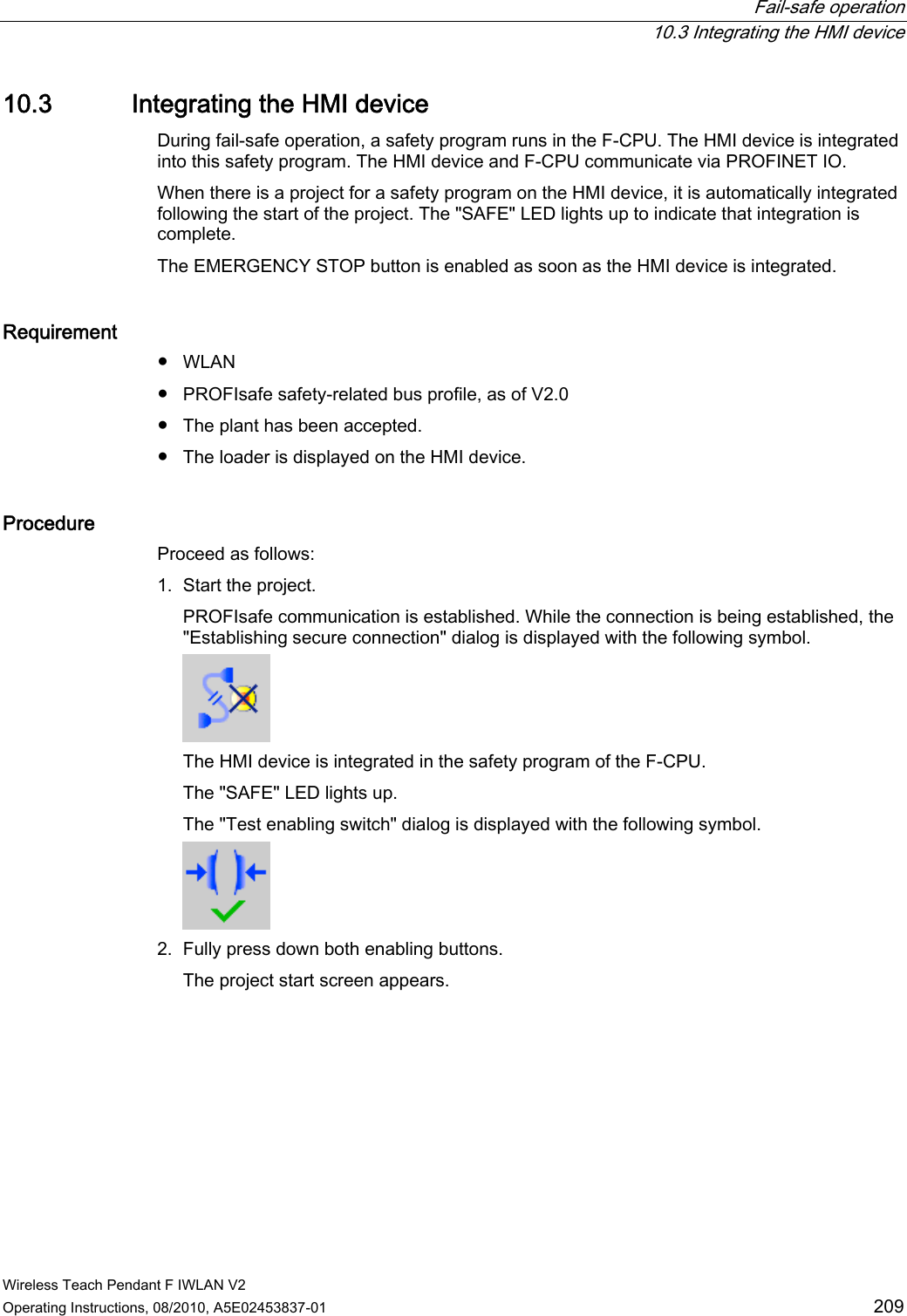
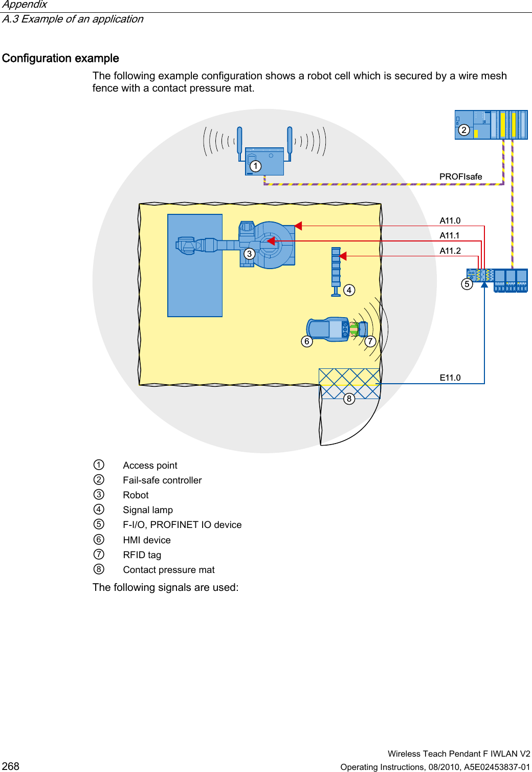
Siemens AG SIMATIC WTP 277F IWLAN Wireless Teach Pendant F IWLAN V2
Siemens >
Contents
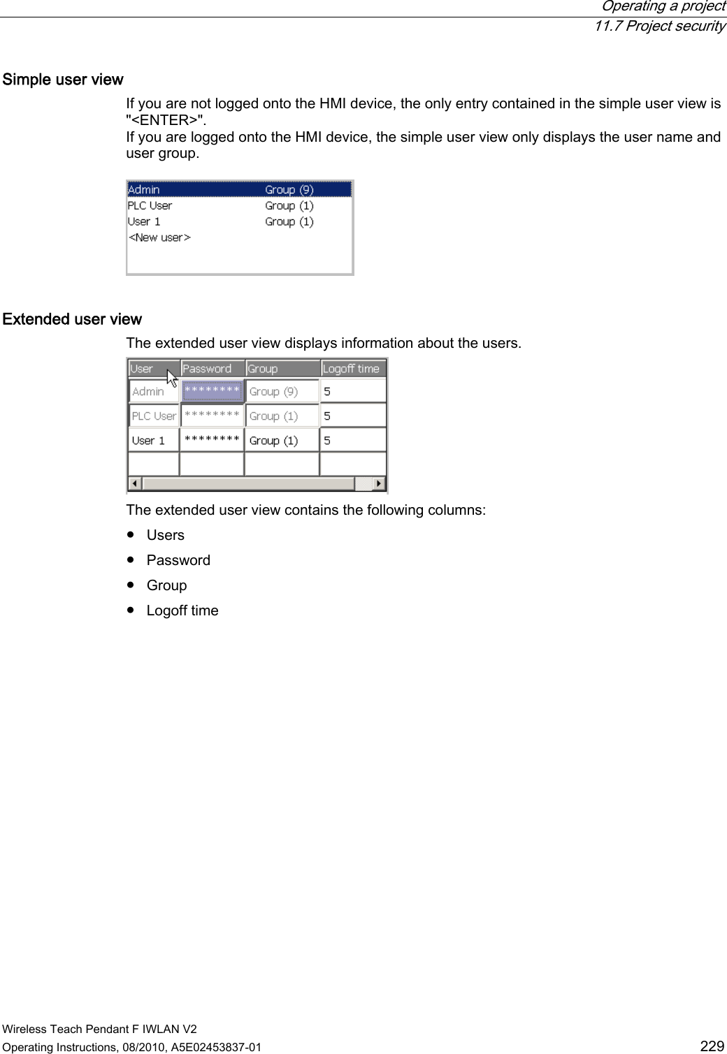
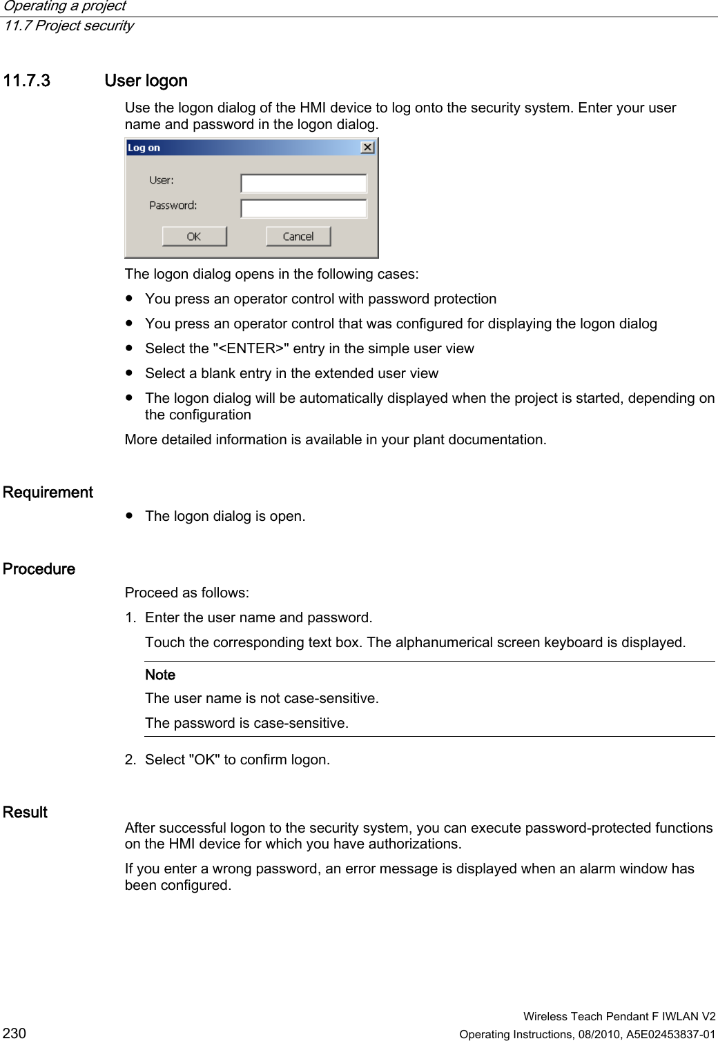
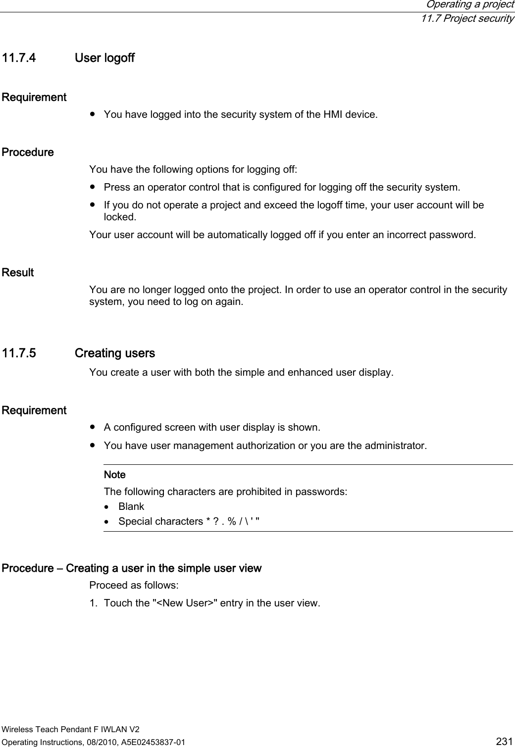
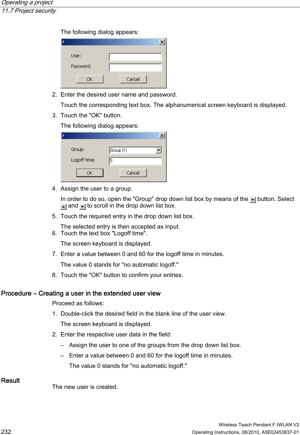
- 1. Users Manual p1
- 2. Users Manual p2
- 3. Users Manual p3
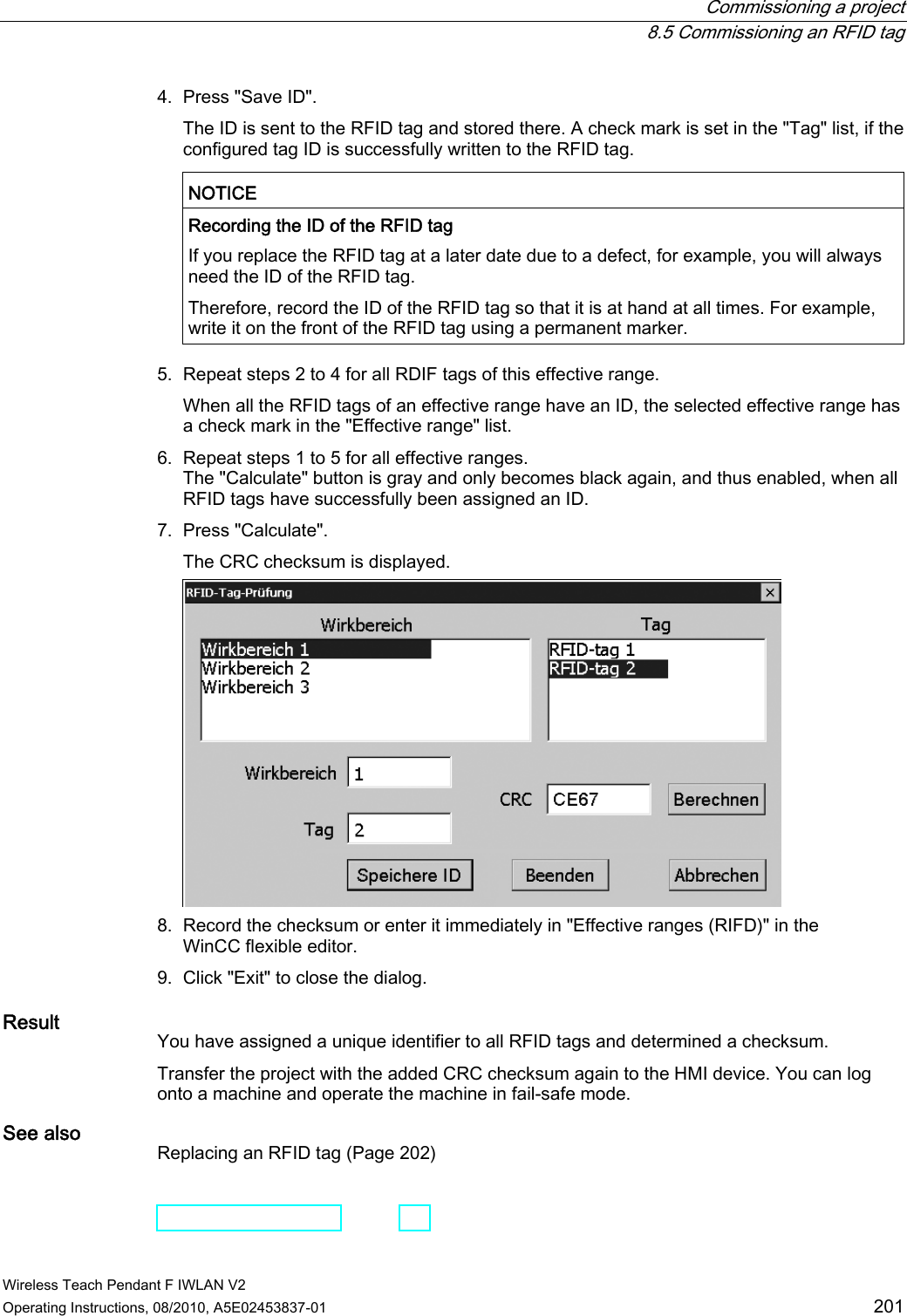
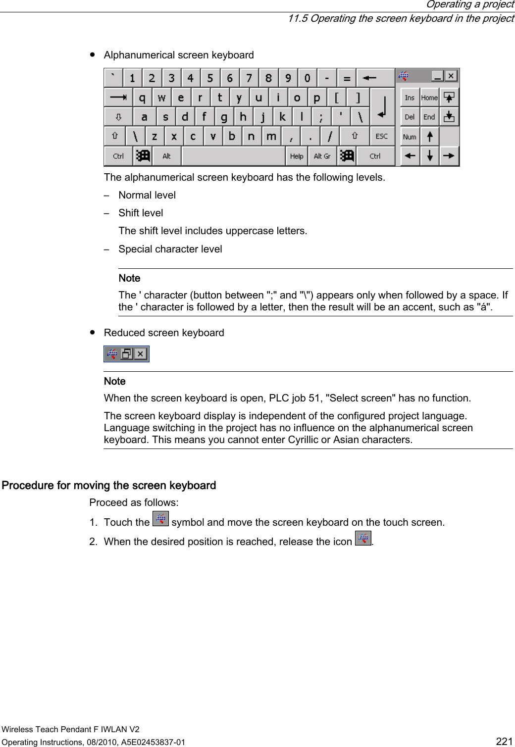
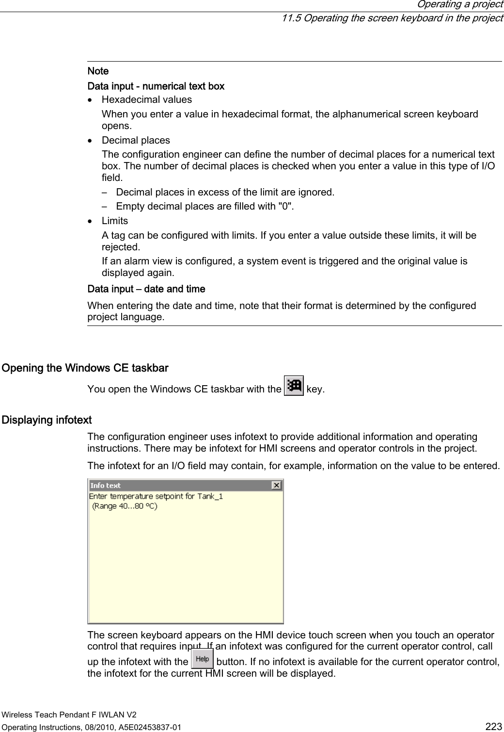
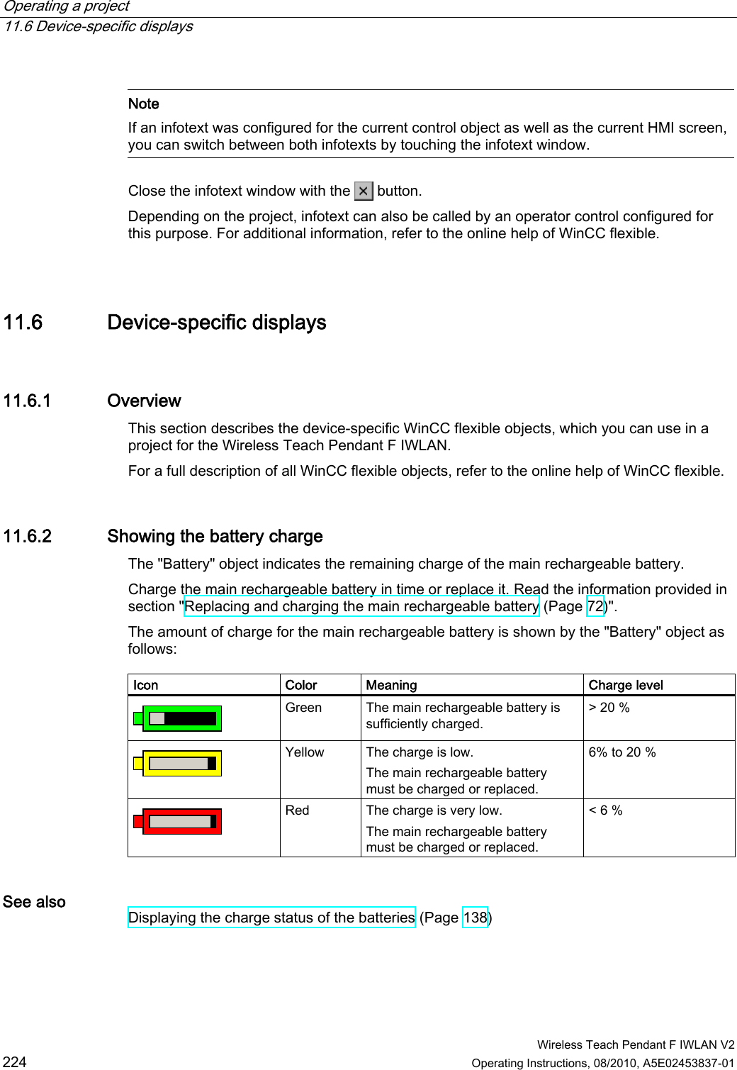
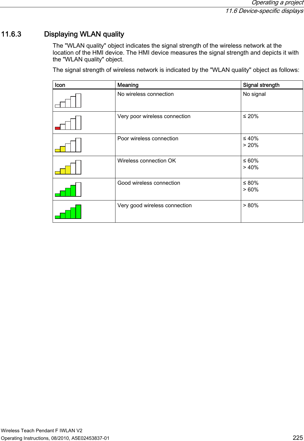
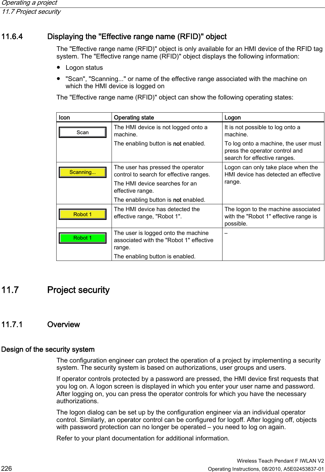
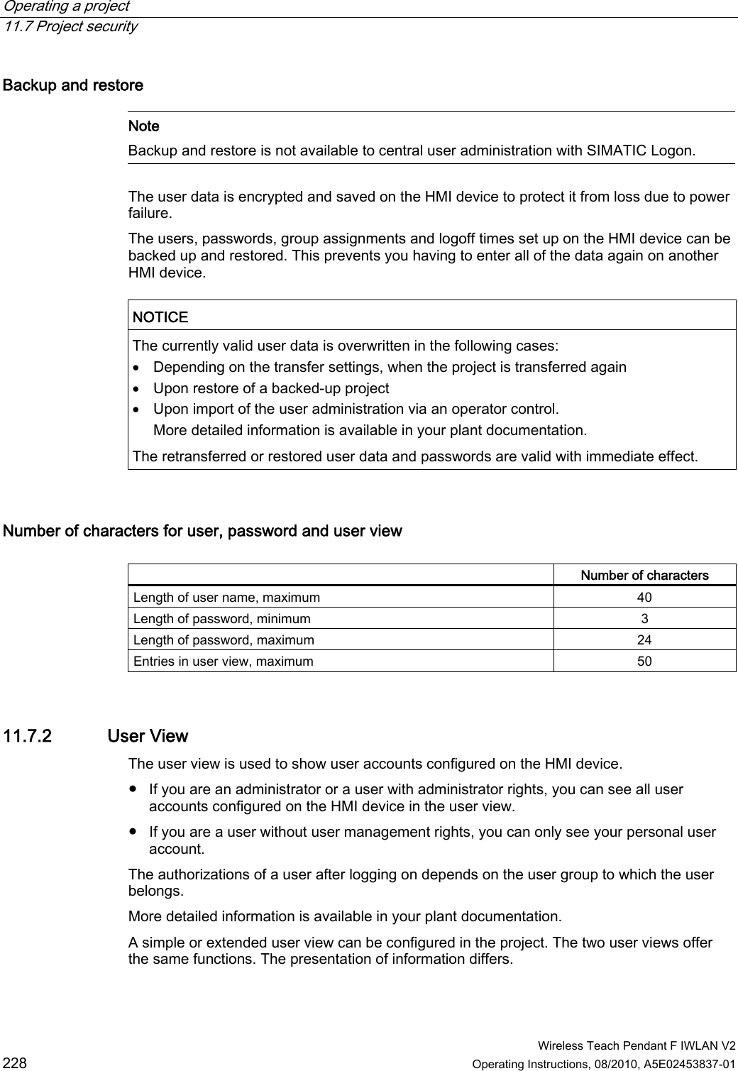
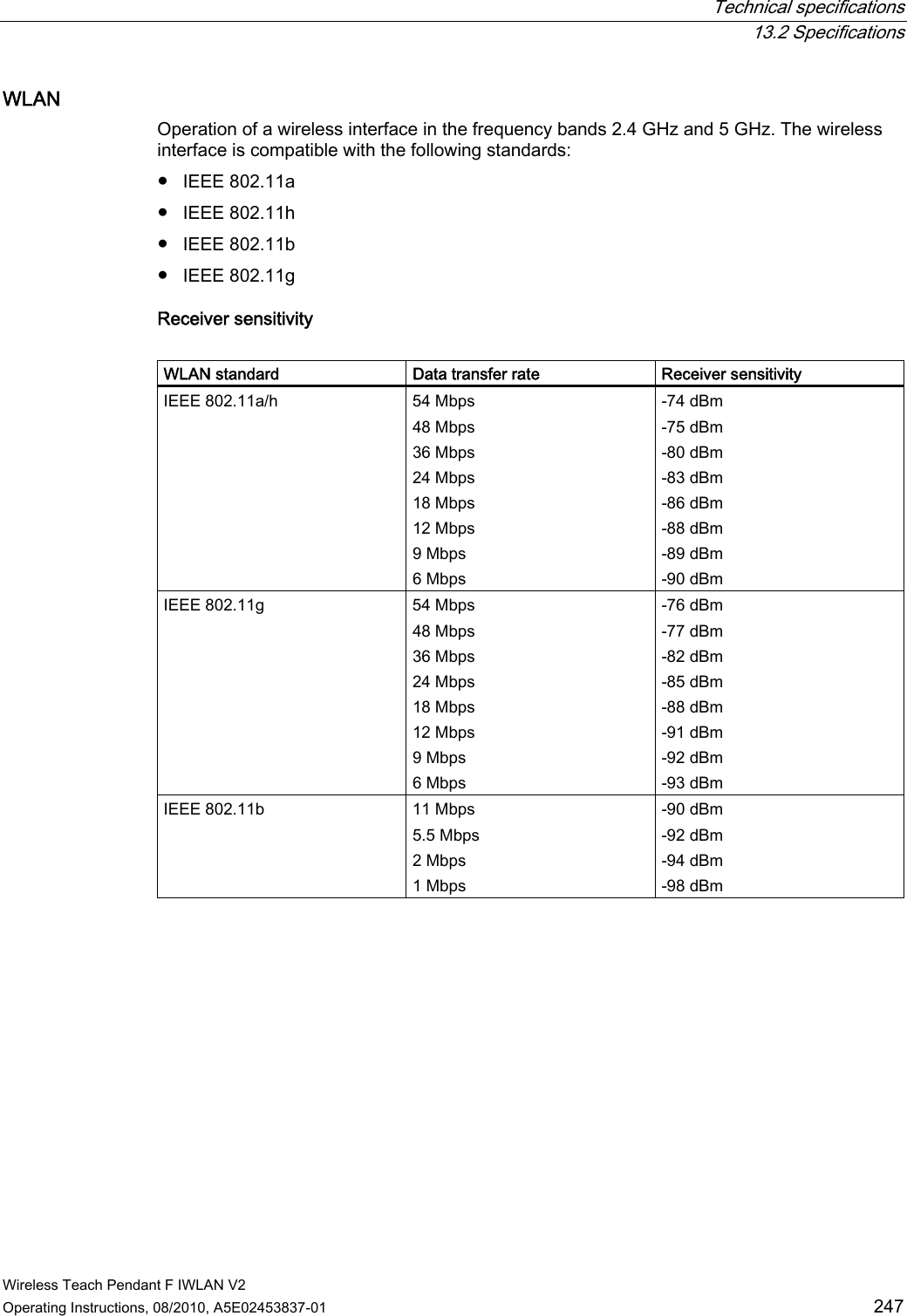
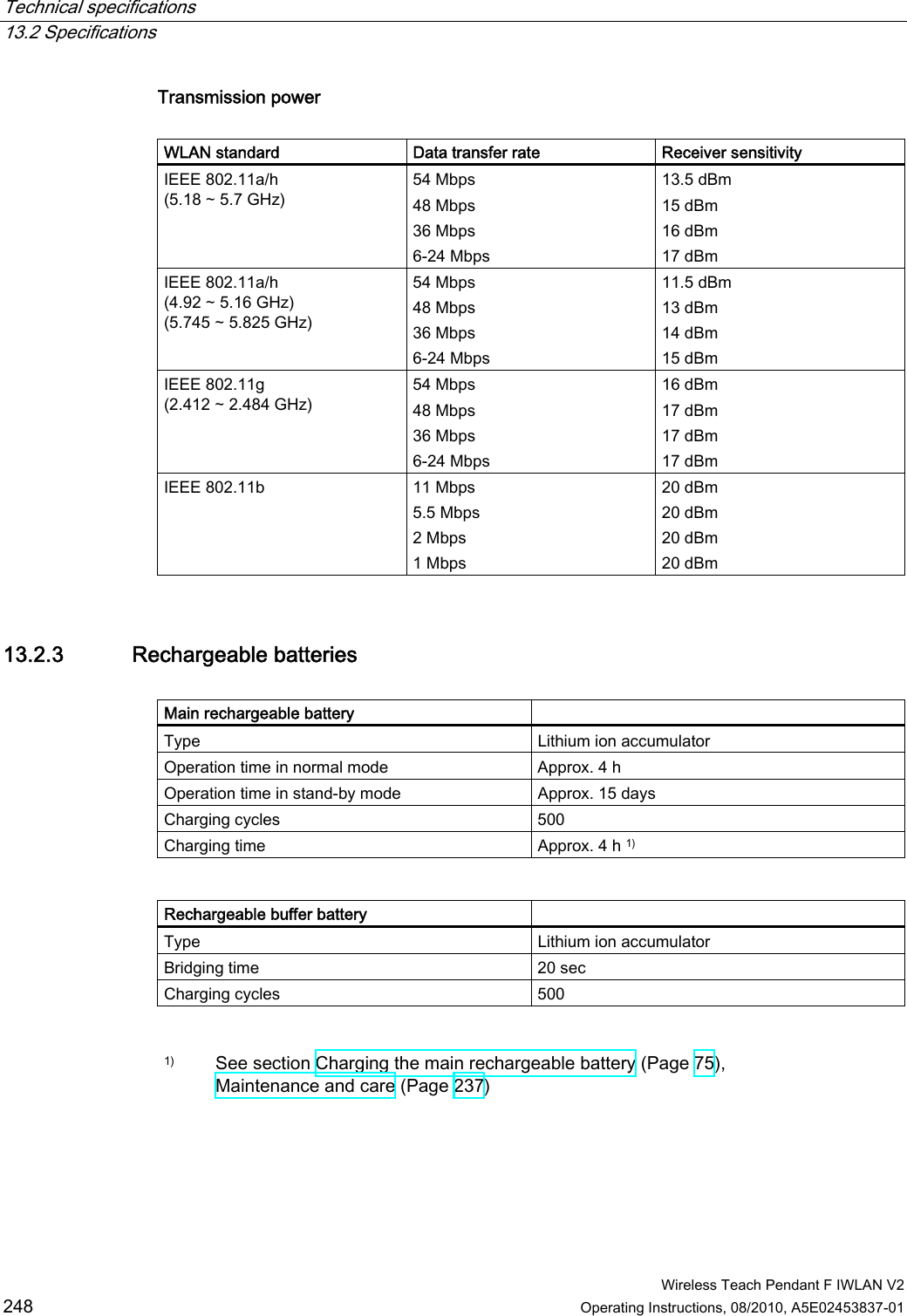
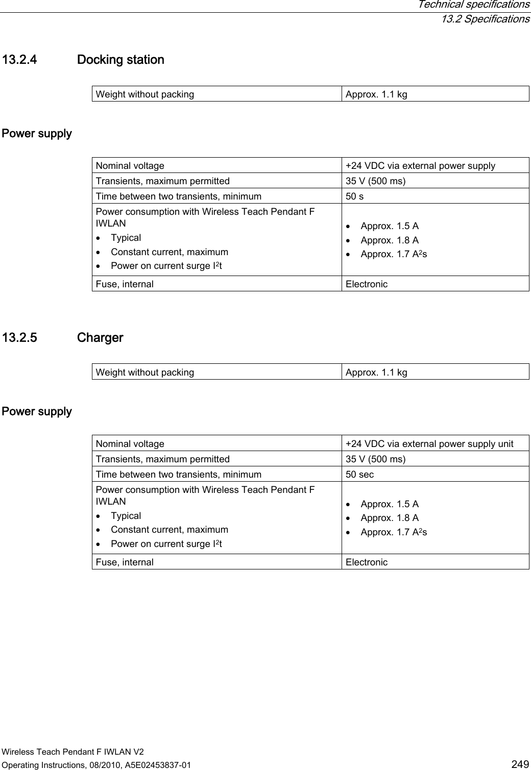
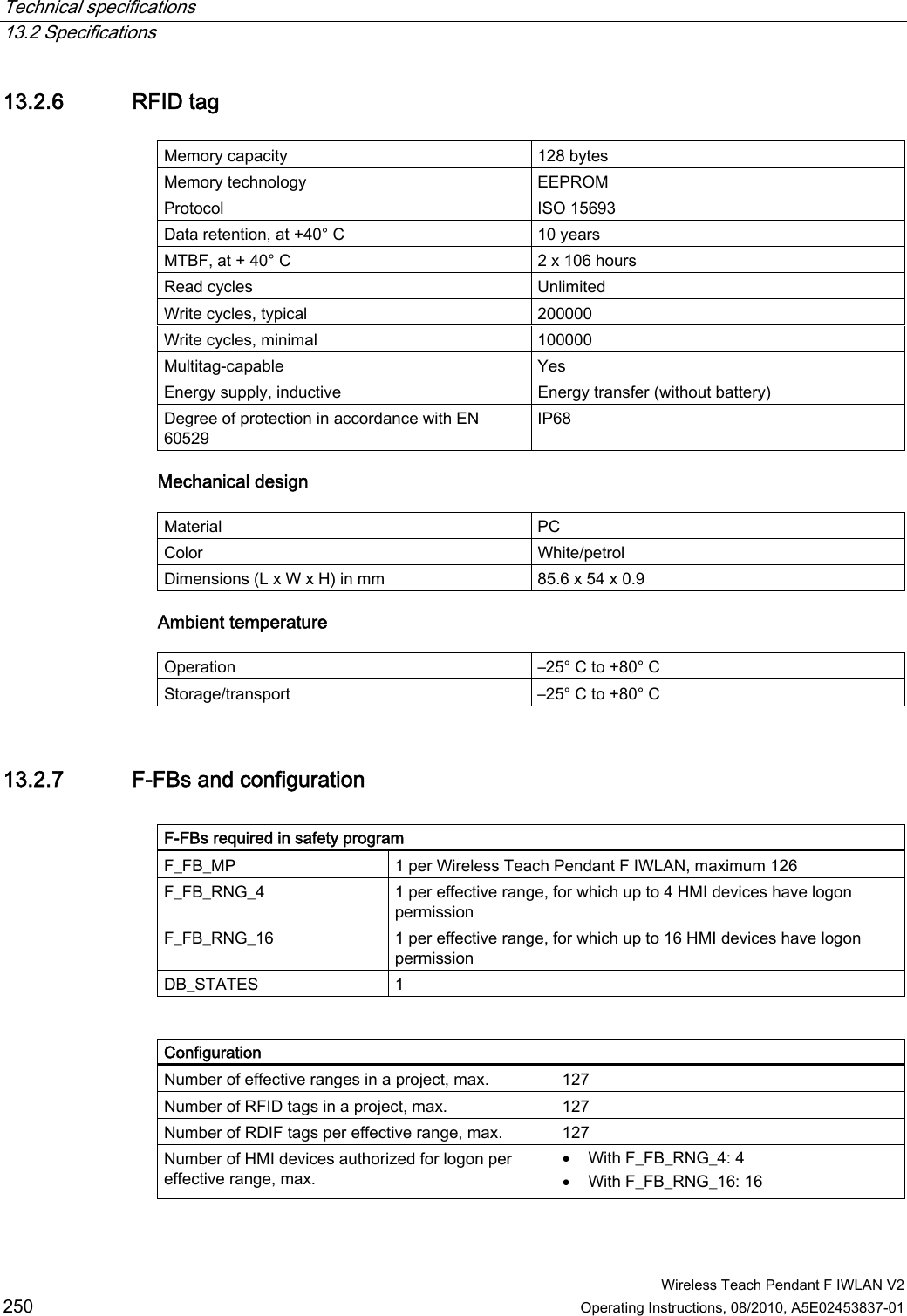
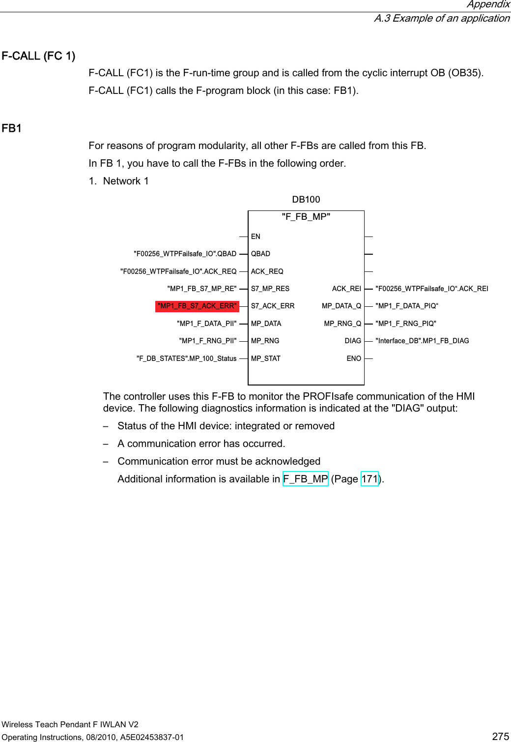
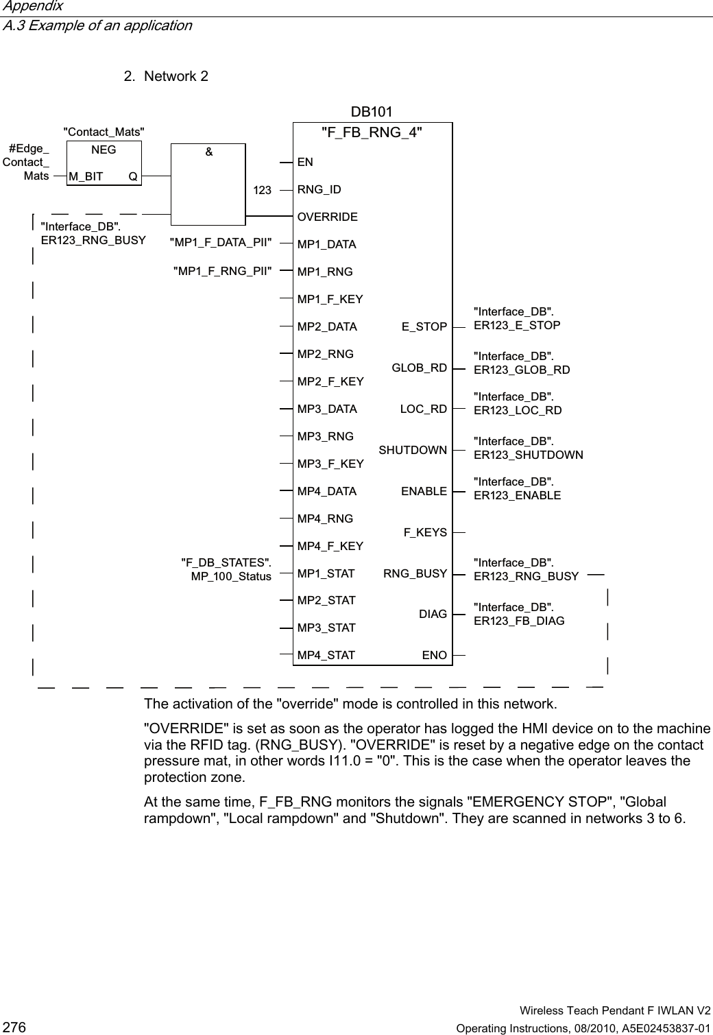
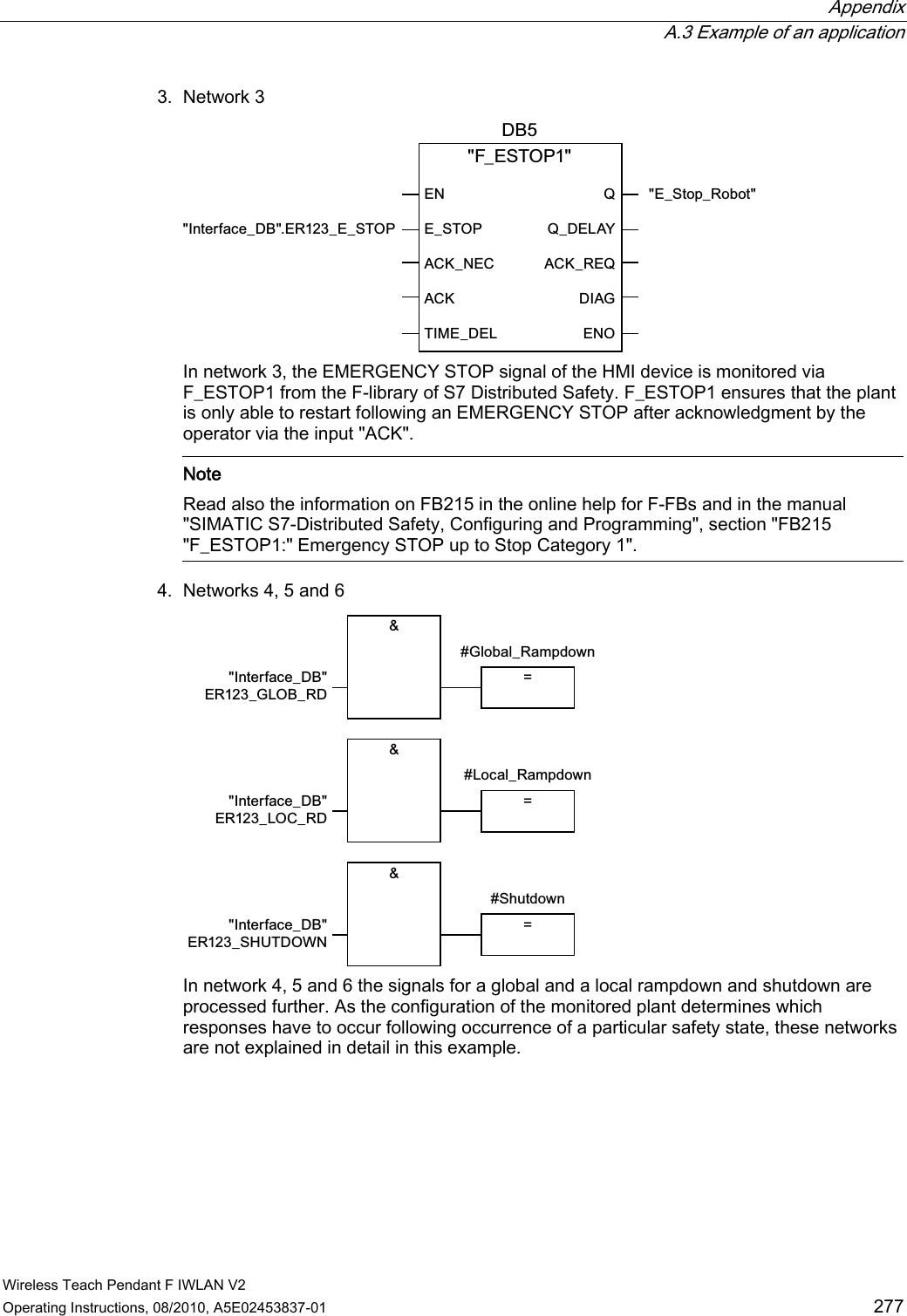
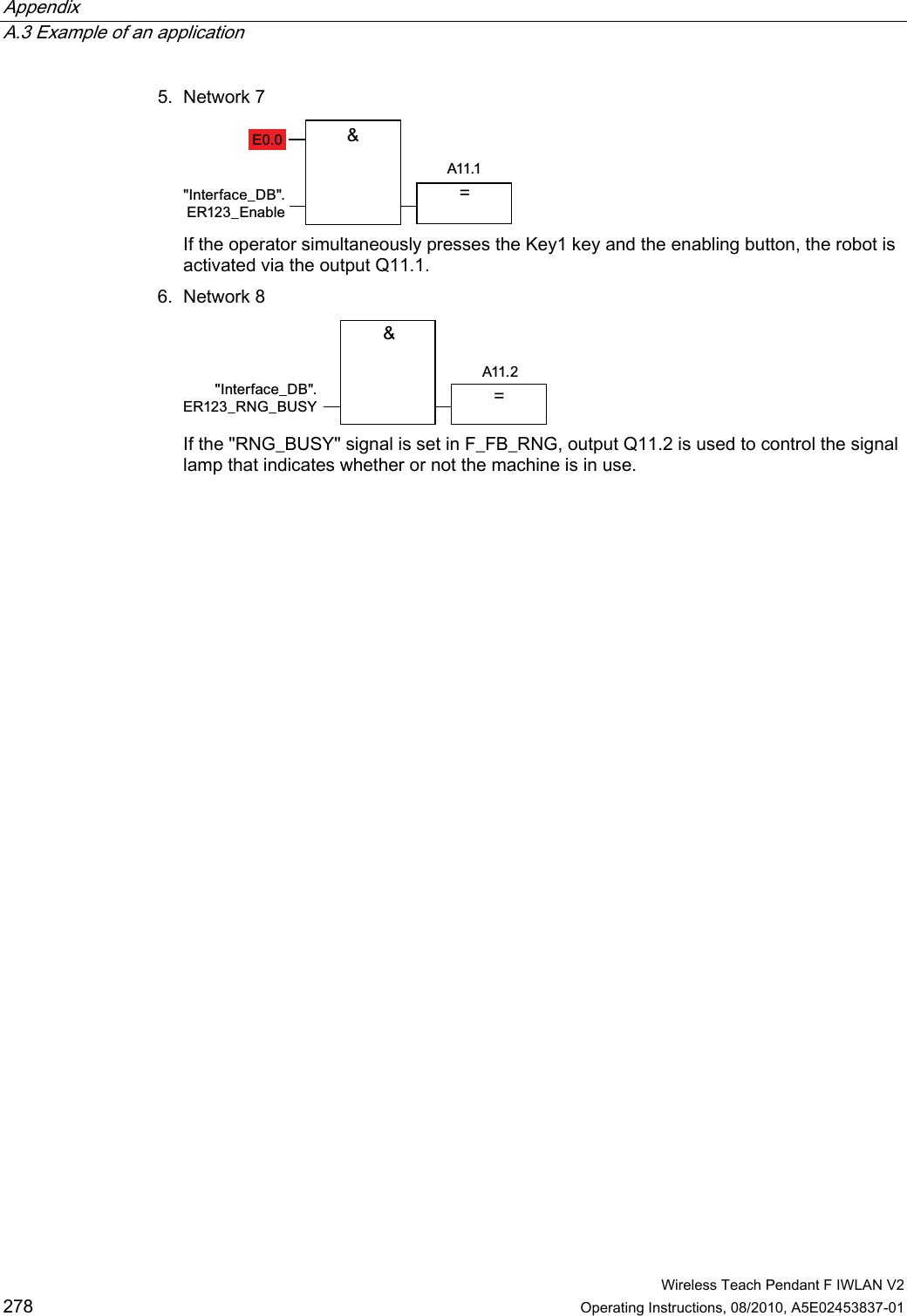
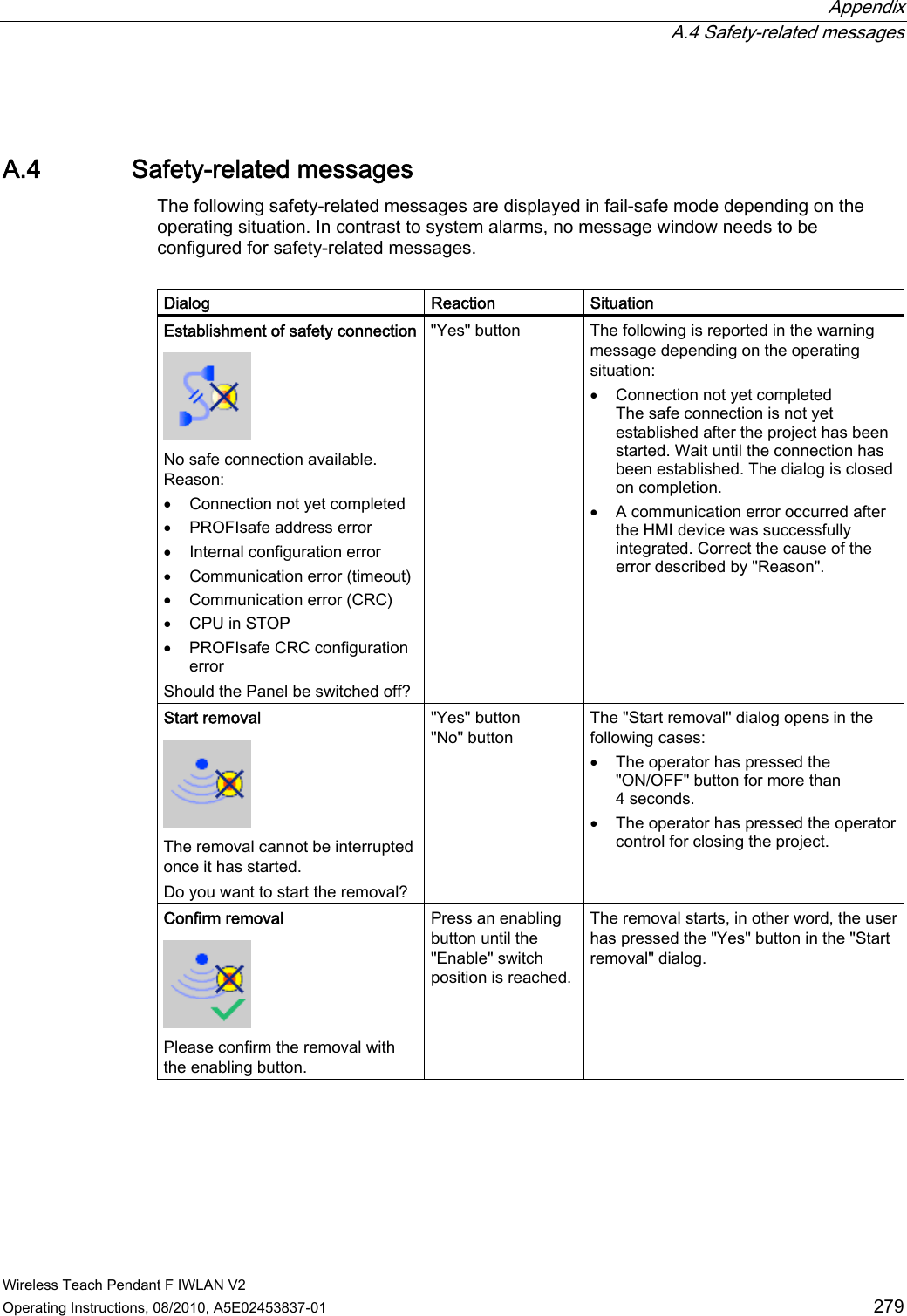
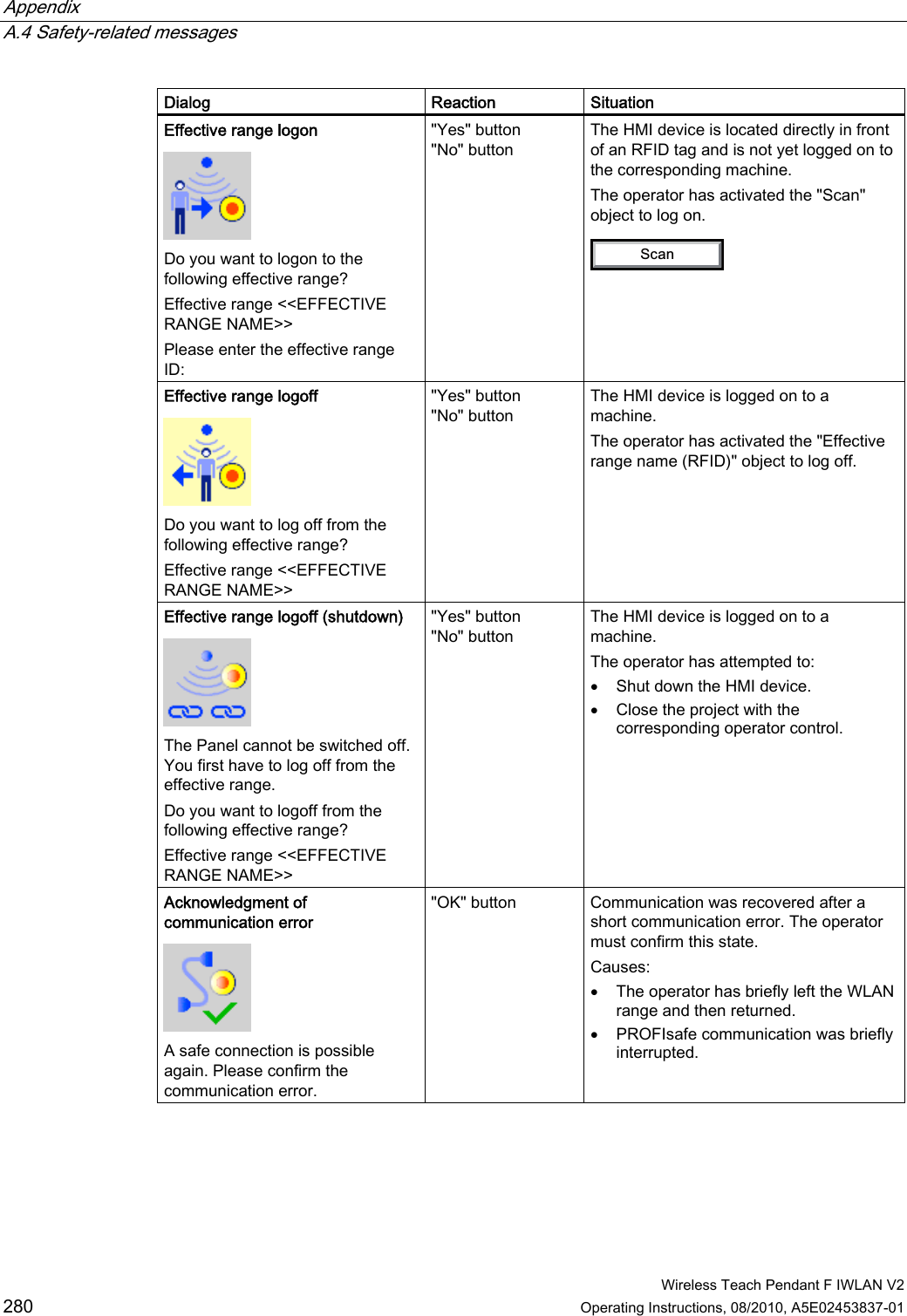
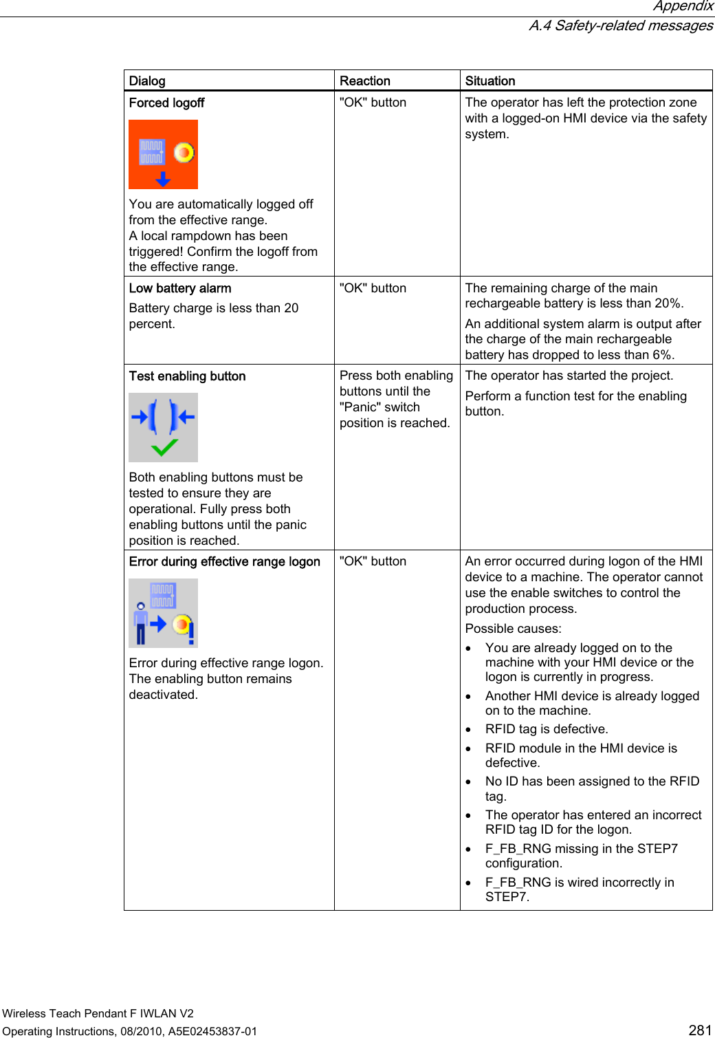
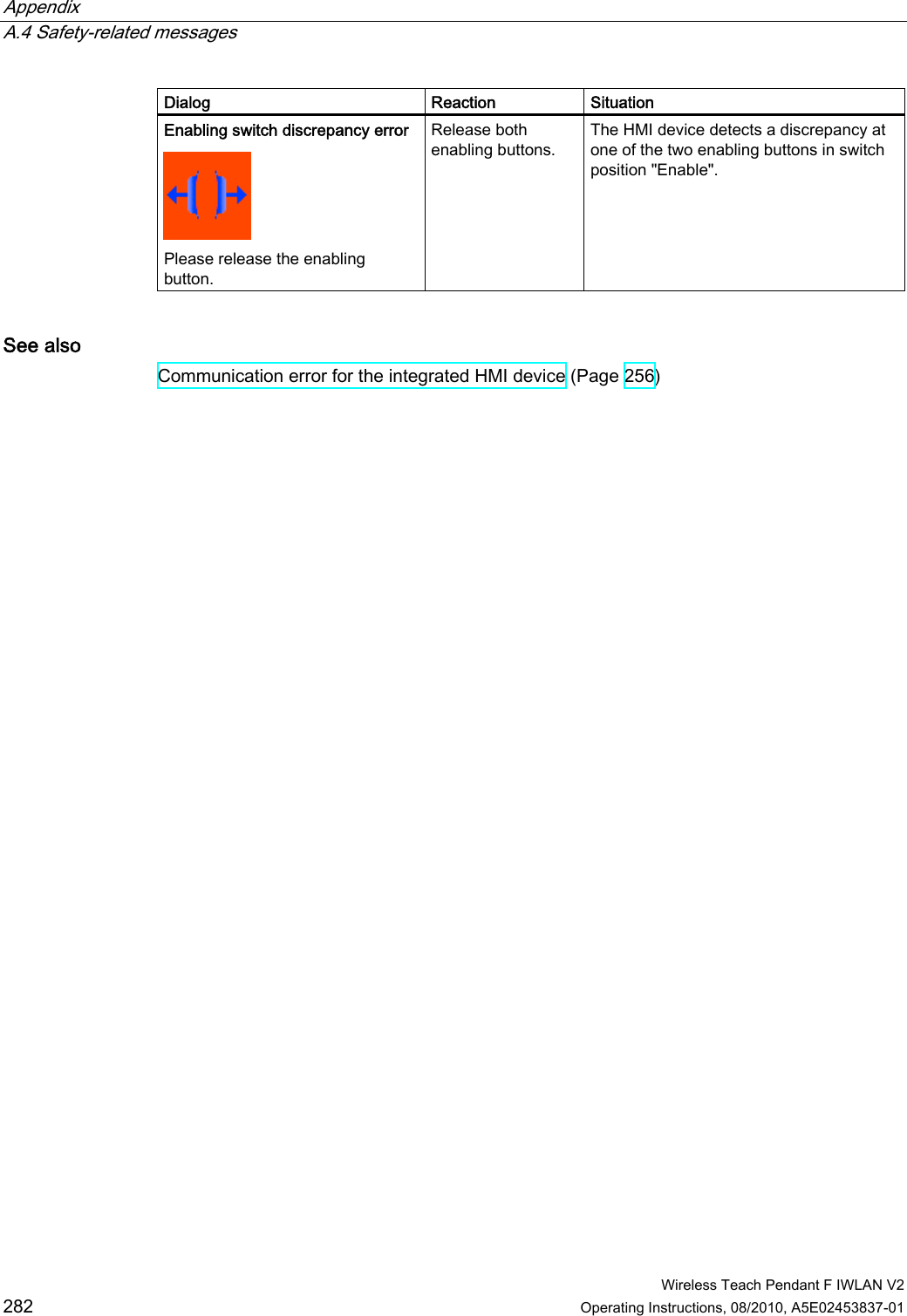
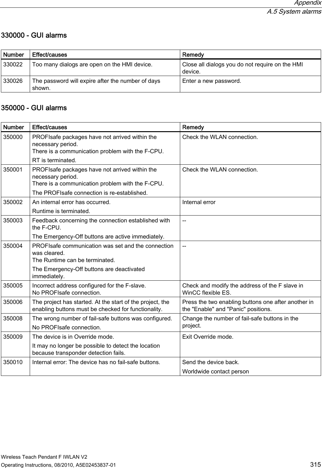
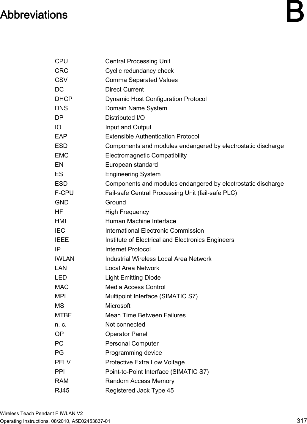
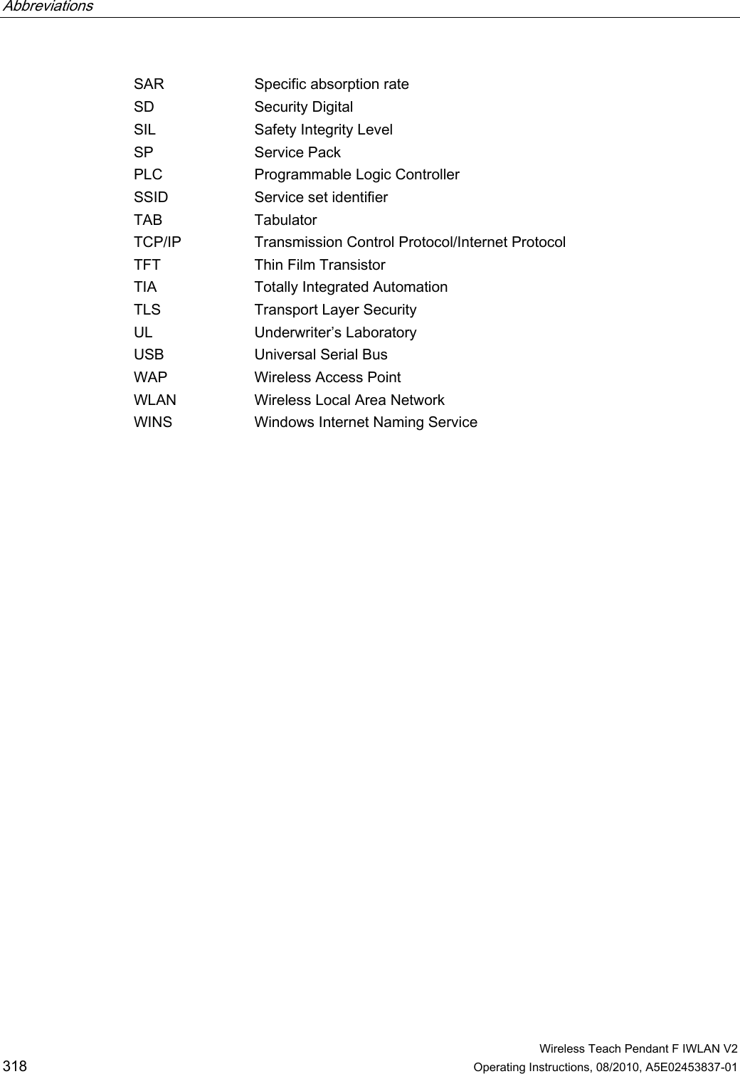
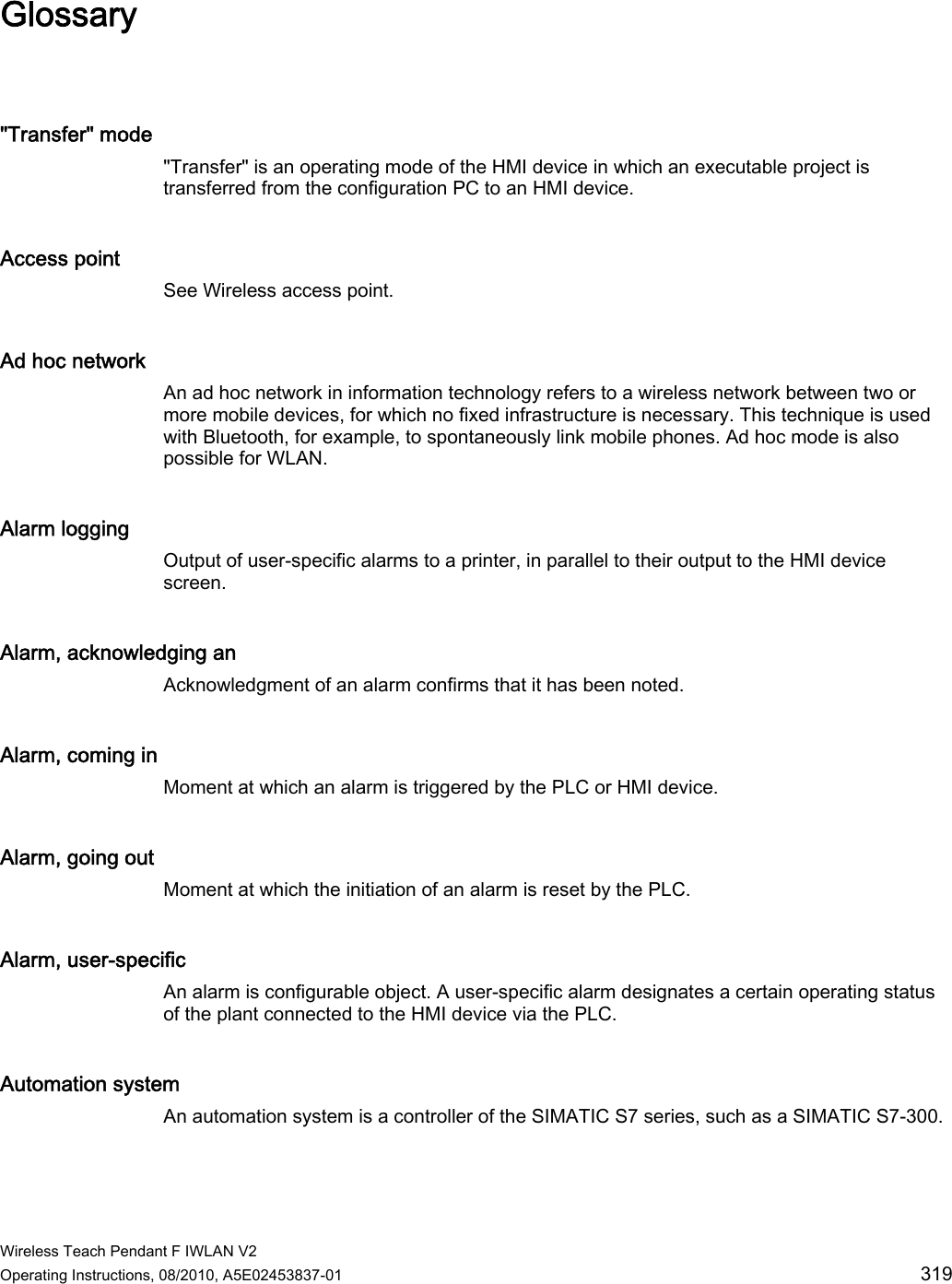
Users Manual p3