Solectek 36WAN1 SkyWay MAX User Manual Base Installatuion Guide
Solectek Corporation SkyWay MAX Base Installatuion Guide
Solectek >
Contents
- 1. Base Installatuion Guide
- 2. Users Manual Part 1
- 3. Users Manual Part 2
- 4. Users Manual Part 3
- 5. Additional User Manual Statement
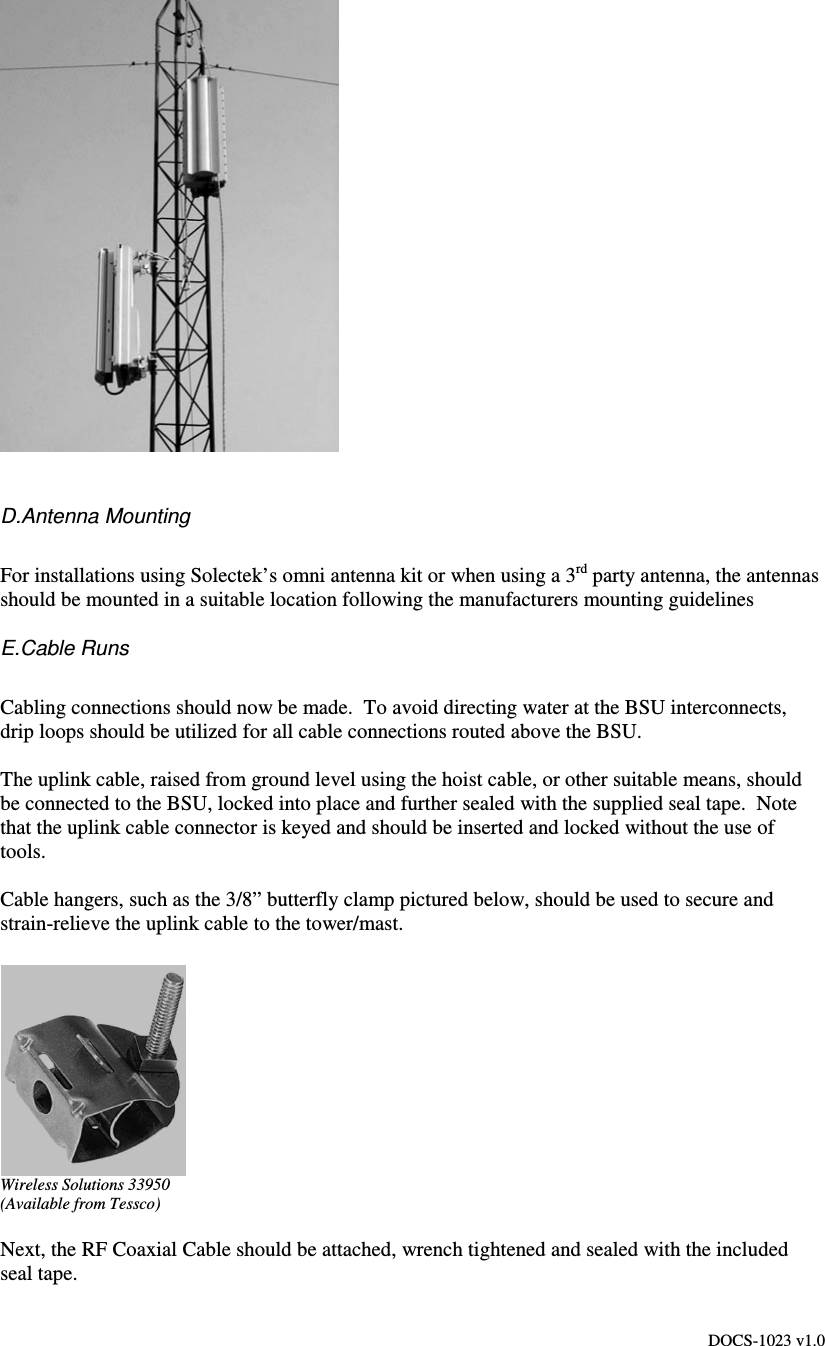
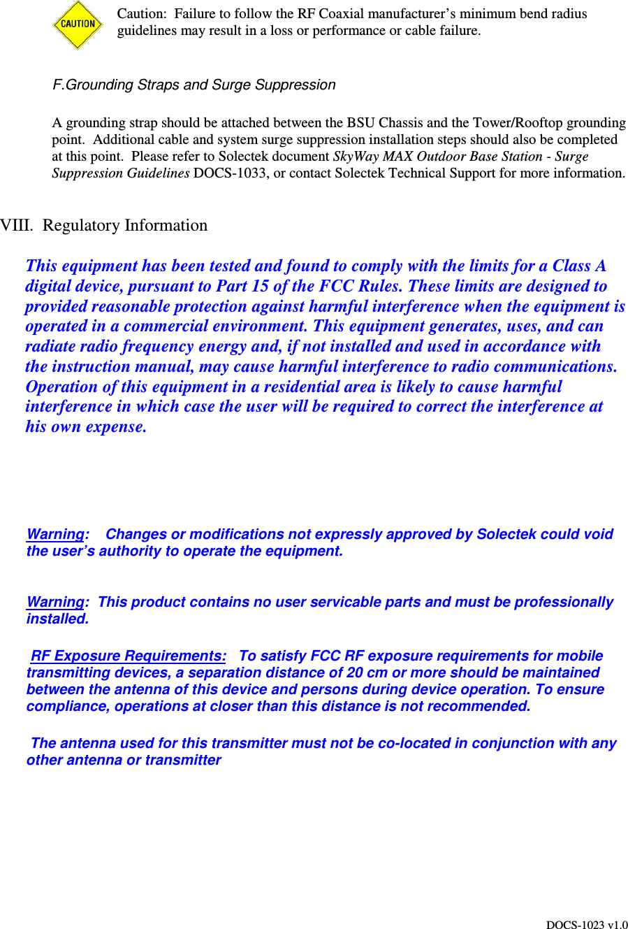
Base Installatuion Guide