Solectek 36WAN1 SkyWay MAX User Manual Base Installatuion Guide
Solectek Corporation SkyWay MAX Base Installatuion Guide
Solectek >
Contents
- 1. Base Installatuion Guide
- 2. Users Manual Part 1
- 3. Users Manual Part 2
- 4. Users Manual Part 3
- 5. Additional User Manual Statement
Base Installatuion Guide

DOCS-1023 v1.0
Outdoor Base Station Installation Guide
ODB-3537
I.Introduction
Congratulations on the purchase of your Solectek SkyWay MAX Outdoor Base Station (BSU). This
document has been supplied to guide and simplify the installation of the SkyWay MAX BSU.
The following Solectek Models are covered herein:
Outdoor Base Stations
ODB-3537
Base Station Antenna Kits
ANT-OMNI35
ANT-SECT35
Base Station Power Kit
PWR-ODB35
II.Disclaimers
Installation of the SkyWay MAX Outdoor Base Station should only proceed once careful consideration has
been given to the Wireline and RF System design of the complete Network. Issues such as cell planning,
network backhaul, tower siting and surge suppression all require careful, advanced planning. Please
contact Solectek or your local representative for more information.
Solectek shall not be responsible for any operation of this product which is in violation of local law,
creates interference harmful to other local devices, or results in a malfunction of this product caused
by outside interference.
This device must be professionally installed and used in strict accordance with the manufacturer's
instructions. However, there is no guarantee that interference to radio communications will not occur
in a particular commercial installation. In case the device does cause harmful interference with an
authorized radio service, the user/ operator shall promptly stop operating the device until harmful
interference has been limited. Solectek Corporation is not responsible for any radio or television
interference caused by unauthorized modification of this device or the substitution or attachment of
connecting cables and equipment other than specified by Solectek Corporation. The correction of
interference caused by such unauthorized modification, substitution, or attachment will be the
responsibility of the user.
Solectek shall not be liable for damages associated with the installation and use of this product,
including but not limited to personal or property damage, business losses or infringement of local or
national laws.
DOCS-1023 v1.0
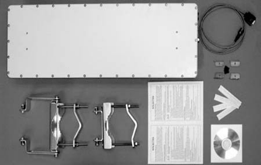
III.Package Contents
A.Base Station Unit
Included in the SkyWay MAX BSU are the follow parts:
- BSU chassis, 1pc
- RS232 console cable, 1pc
- Pre-assembled, mast mounting kit, 1 set
- Angle bracket and screw, 4 sets
- Outdoor cable seals, 4 pcs
- Documentation CD, 1pc
- Reference Card, 1pc
B.Optional Kits
If purchased, the following parts are included in the SkyWay MAX Kits:
Adjustable Sectoral Antenna Kit
- 3.3-3.7 GHz, 45-120deg Adjustable Sectoral Antenna, 1pc
- Chassis Mounting Kit, 1 set
- RF Cable, 1 pc
- Outdoor cable seals, 2 pcs
- Mounting Instructions
Omni Antenna Kit
- 3.3-3.7 GHz, Omni Antenna, 1pc
- Mast Mounting Kit, 1 set
- 8 foot RF Cable, 1 pc
- Outdoor cable seals, 2 pcs
- Mounting Instructions
Single Base Station Power Kit
- 120W AC-DC, 48V Indoor Power Supply, 1pc
- AC Power Cord
- Indoor Power Injector, 1pc
DOCS-1023 v1.0
IV.Access
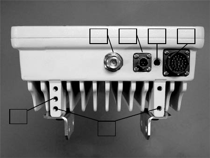
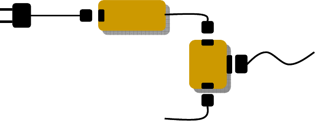
A.Base Station Port Panel
The bottom face of the outdoor base station contains 3 access ports as described herein.
Legend
1 N-type RF port
2 RS232 Header
3 Seal port (not used by customer functions)
4 Uplink Header
5 Tapped Chassis Ground Point
6 Tapped Accessory Mounting Points
B.RF Port
The N-type RF Port connects the BSU chassis to the desired antenna, including Solectek’s
integrated, adjustable sectoral kit, external omni kit or any appropriate 3rd party product.
The RF Port may be connected to an RF Cavity Filter and/or Surge Suppressor, if desired. Please
contact Solectek Technical Support for configuration support and options.
C.RS232 Port
An RS232 management port is available for benchtesting and on-tower debugging. It is not
designed, however for access during normal BSU operation.
1
2
3
4
5
6
DOCS-1023 v1.0
D.Seal Port
This sealed access port is used during the manufacturing process to ensure each Base Station is
completely dust and watertight. Customers should not access this Port.
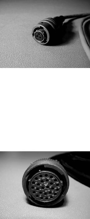
E.Uplink Port
The Uplink Cable is the single umbilical cord connecting the BSU to the indoor source of power
and data. Functions within the cable include the transport of: 10/100 Ethernet signals, GPS
strobe, diagnostic channels and -48V DC power.
Pre-built Uplink Cables to 80m are available directly from Solectek or your local Solectek
representative.
F.Grounding Point
Tapped hole used for attachment of grounding wire/strap, critical for proper surge suppression.
G.Accessory Mounting Point
Taped hole used for the optional attachment of external antenna surge suppressors and/or RF
cavity filters. Please contact Solectek Technical Support for configuration support and options.
V.Preparation
A.Tools
The following tools are required for the proper installation of the SkyWay MAX BSU:
- Gin pole / hoist with clamp
DOCS-1023 v1.0
- ½” ratchet-action box-end wrench
- 7/16” box-end wrench
- ¼” Allen wrench
- Slip Joint Pliers
- Utility knife
- Cable seals
B.BSU and Cables
The BSU and both Uplink and RF Cable should be fully prepared and pretested prior to
installation.
C.Angle Bracket Installation
All four (4) angle brackets should be attached and tightened to the rear of the BSU with the
supplied screws and washers.
D.Mast Mounting Kit
The two part BSU Mast Mounting kit is designed to accommodate pipe diameters from 1” to
4 ½ inches
and provide up to 10 degrees of vertical tilt. Note that the two
Mounting Kit assemblies can be swapped (upper for lower) on the
BSU, to provide tilt in the opposite direction.
The BSU mast mounting kit should be securely attached to the BSU
angle brackets, installed in the previous step.
DOCS-1023 v1.0
E.Antenna Options
The BSU Antenna and mounting kit should be prepared in advance of Installation. When using
Solectek’s Integrated, Adjustable Sectoral Antenna, the antenna should be mounted to the BSU
and adjusted to the desired beamwidth while still on the ground.
F.RF Cavity Filters / Surge Suppressors
All Filters and Surge Suppressors should be prepared in advance of the installation. In the case of
Solectek provided filters or suppressors, the devices can be mounted directly to the BSU
simplifying cabling and minimizing RF losses.
VI. Indoor Provisioning
A. Single Sector BSU Site
Provisioning a single sector BSU involves preparing and installation of the PWR-ODB35 power
supply kit. Components of this kit should be located in a network/power closet and at the location
of the ASN switch/gateway . Connection of the kit is as follows:
B. Multi-Sector BSU Site
Provisioning the network and power connections of a multi-sector BSU site involves the use of
Solectek’s IDU Controller System. Please refer to Solectek document DOCS-1025, “SkyWay
MAX Indoor Base Station Controller - Installation Guide” for detailed provisioning instructions
VII.Outdoor Installation
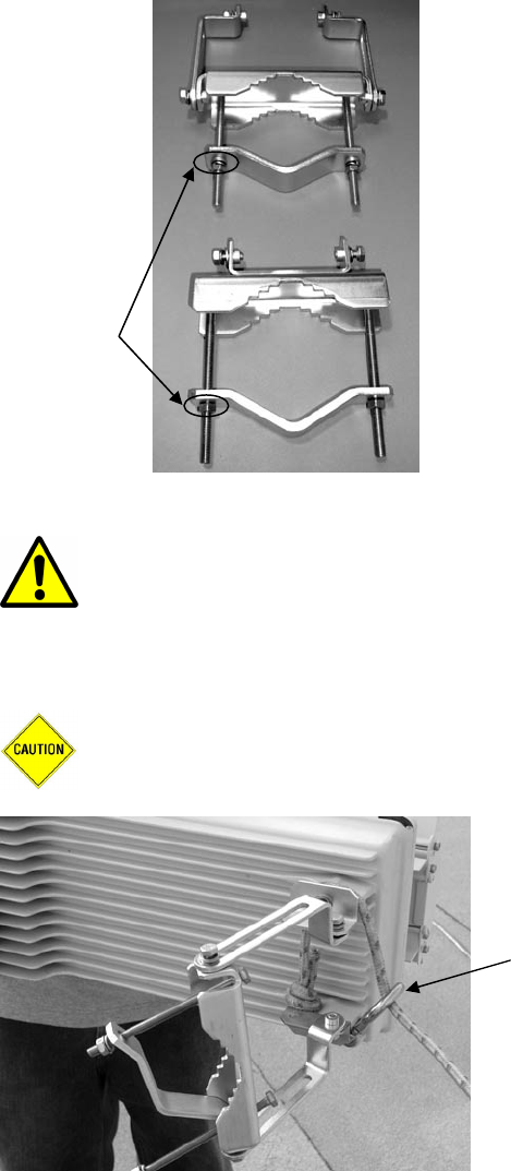
A.Staging
It is recommended to stage and verify presence of all necessary gear at an indoor location prior to
installation. At this point, one of the mast clamp nuts should be removed from both the upper and
lower mounting bracket. This will allow the clamping jaw to rotate and to clear the mast during
positioning.
Power
Injector
Power
Injector
to BSU
AC/DC
Power Supply
AC/DC
Power Supply
100-240
VAC
Uplink
Cable
to Switch/
ASN gateway
Cat5
48VDC
Power
Injector
Power
Injector
Power
Injector
Power
Injector
to BSU
AC/DC
Power Supply
AC/DC
Power Supply
100-240
VAC
Uplink
Cable
to Switch/
ASN gateway
Cat5
48VDC
DOCS-1023 v1.0
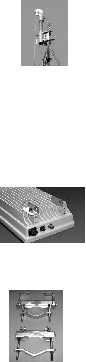
B.Lifting
Warning: The SkyWay MAX BSU shall be installed by tower and radio
professionals ONLY. All appropriate safety equipment should be utilized during
installation.
Route the lower end of the hoist cable around the top legs of the BSU, behind the Angle Brackets,
attaching the clamp to the cable.
Caution: Damage to the RF Cable may occur if the BSU is rested on its bottom
face.
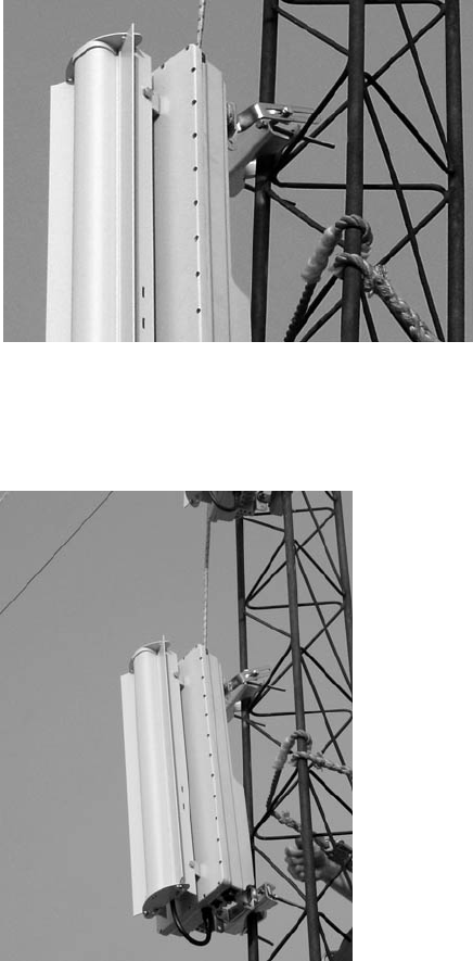
Using a gin pole or alternate hoist arrangement, the BSU should be carefully lifted to the desired
tower or rooftop location and position.
Remove in
preparation
for lift
Hoist
cable
with clamp
DOCS-1023 v1.0
The BSU Mast Mounting kit should then be fastened and secured to the designated mast pole. It is
generally easiest to secure the fixed (non-tilting) bracket first.
C.Alignment
At this point, the BSU can be rotated into suitable horizontal and vertical alignment. Once adjusted, the mast
clamps should be fully tightened and the hoist cable removed.
DOCS-1023 v1.0
D.Antenna Mounting
For installations using Solectek’s omni antenna kit or when using a 3rd party antenna, the antennas
should be mounted in a suitable location following the manufacturers mounting guidelines
E.Cable Runs
Cabling connections should now be made. To avoid directing water at the BSU interconnects,
drip loops should be utilized for all cable connections routed above the BSU.
The uplink cable, raised from ground level using the hoist cable, or other suitable means, should
be connected to the BSU, locked into place and further sealed with the supplied seal tape. Note
that the uplink cable connector is keyed and should be inserted and locked without the use of
tools.
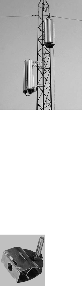
Cable hangers, such as the 3/8” butterfly clamp pictured below, should be used to secure and
strain-relieve the uplink cable to the tower/mast.
Wireless Solutions 33950
(Available from Tessco)
Next, the RF Coaxial Cable should be attached, wrench tightened and sealed with the included
seal tape.

DOCS-1023 v1.0
Caution: Failure to follow the RF Coaxial manufacturer’s minimum bend radius
guidelines may result in a loss or performance or cable failure.
F.Grounding Straps and Surge Suppression
A grounding strap should be attached between the BSU Chassis and the Tower/Rooftop grounding
point. Additional cable and system surge suppression installation steps should also be completed
at this point. Please refer to Solectek document SkyWay MAX Outdoor Base Station - Surge
Suppression Guidelines DOCS-1033, or contact Solectek Technical Support for more information.
VIII. Regulatory Information
This equipment has been tested and found to comply with the limits for a Class A
digital device, pursuant to Part 15 of the FCC Rules. These limits are designed to
provided reasonable protection against harmful interference when the equipment is
operated in a commercial environment. This equipment generates, uses, and can
radiate radio frequency energy and, if not installed and used in accordance with
the instruction manual, may cause harmful interference to radio communications.
Operation of this equipment in a residential area is likely to cause harmful
interference in which case the user will be required to correct the interference at
his own expense.
Warning: Changes or modifications not expressly approved by Solectek could void
the user’s authority to operate the equipment.
Warning: This product contains no user servicable parts and must be professionally
installed.
RF Exposure Requirements: To satisfy FCC RF exposure requirements for mobile
transmitting devices, a separation distance of 20 cm or more should be maintained
between the antenna of this device and persons during device operation. To ensure
compliance, operations at closer than this distance is not recommended.
The antenna used for this transmitter must not be co-located in conjunction with any
other antenna or transmitter